a coupled two degree of freedom pull-in model for micromirrors under capillary force
TRANSCRIPT
7/30/2019 A coupled two degree of freedom pull-in model for micromirrors under capillary force
http://slidepdf.com/reader/full/a-coupled-two-degree-of-freedom-pull-in-model-for-micromirrors-under-capillary 1/8
Acta Mech 223, 387–394 (2012)DOI 10.1007/s00707-011-0558-z
Ali Darvishian · Hamid Moeenfard ·
Mohammad Taghi Ahmadian · Hassan Zohoor
A coupled two degree of freedom pull-in modelfor micromirrors under capillary force
Received: 19 April 2011 / Published online: 1 November 2011© Springer-Verlag 2011
Abstract The current paper presents a two degree of freedom model for the problem of micromirrors undercapillary force. The principal of minimum potential energy is employed for finding the equilibrium equationsgoverning the deflection and the rotation of the micromirror. Then, using the implicit function theorem, acoupled bending–torsion model is presented for pull-in characteristics of micromirrors under capillary forceand the concept of instability mode is introduced. It is observed that with increasing ratio of bending andtorsion stiffness, the dominant instability mode changes from bending mode to the torsion mode. In orderto verify the accuracy of the coupled model, static behavior of a group of micromirrors is investigated bothanalytically using the presented model and numerically using the commercial finite element software ANSYS.It is observed that results of the coupled model match well with the results of finite element simulations, butthey both deviate considerably from the results of the pure torsion model. The presented coupled model canbe used for safe and stable design of micromirrors under capillary force.
1 Introduction
The technology of MEMS devices has experienced lots of progress. Their low manufacturing cost, batchproduction, light weight, small size, durability, low energy consumption and compatibility with integratedcircuits make them extremely attractive [1,2]. Successful MEMS devices rely not only on well-developedfabrication technologies but also on the knowledge of device behavior, based on which a favorable structure of the device can be forged [3]. The important role of MEMS devices in optical systems has initiated the develop-ment of a new class of MEMS called MicroOptoElectroMechanical Systems (MOEMS), which mainly includemicromirrors and torsional microactuators. These devices have found a variety of applications such as digitalmicromirror devices (DMD) [4], optical switches [5], micro scanning mirrors [6] and optical cross-connects[7,8].
The existence of a liquid bridge between two objects results in a capillary force [9]. Their existence even
in low relative humidity is observed experimentally [10]. Parallel plate MEMS actuators are conventionallyfabricated by forming a layer of a plate or beam material on the top of a sacrificial layer of another materialand wet etching the sacrificial layer. In this process, a capillary force can be easily formed and in the case of poor design, the structure will collapse and adhere to the substrate. Thus, investigating the effect of capillaryforce on micromirrors is extremely important in their design and fabrication.
A. Darvishian · H. MoeenfardSchool of Mechanical Engineering, Sharif University of Technology, Azadi Ave., Tehran, IranE-mail: [email protected]
M. T. Ahmadian (B) · H. ZohoorCenter of Excellence in Design, Robotics and Automation, School of Mechanical Engineering,Sharif University of Technology, Azadi Ave., Tehran, IranE-mail: [email protected]

7/30/2019 A coupled two degree of freedom pull-in model for micromirrors under capillary force
http://slidepdf.com/reader/full/a-coupled-two-degree-of-freedom-pull-in-model-for-micromirrors-under-capillary 2/8
388 A. Darvishian et al.
The effect of capillary force on MEMS devices has been investigated by many researchers. Mastrangeloand Hsu [11,12] studied the stability and adhesion of thin micromechanical structures under capillary force,theoretically and experimentally. Moeenfard et al. [13] studied the effect of capillary force on the static pull-ininstability of fully clamped microplates. The effects of capillary force on the static and dynamic behav-
ior of atomic force microscopes (AFM) are widely assessed [14–16]. Recently, the instability of torsionalMEMS/NEMS microactuators under capillary force was investigated by Guo et al. [17], but in their model,the bending effect of the supporting torsion beams was not considered. On the other hand, Huang et al. [18]showed that torsion models for a micromirror cannot accurately predict the stability limits of electrostaticallyactuated micromirrors. In this paper, it will be shown that the same concern exists for the micromirrors underthe effect of capillary force, and neglecting the bending effect can lead to a considerable error in the predictionof stable limits of micromirrors under capillary force.
2 Problem formulation
2.1 Coupled bending–torsion model
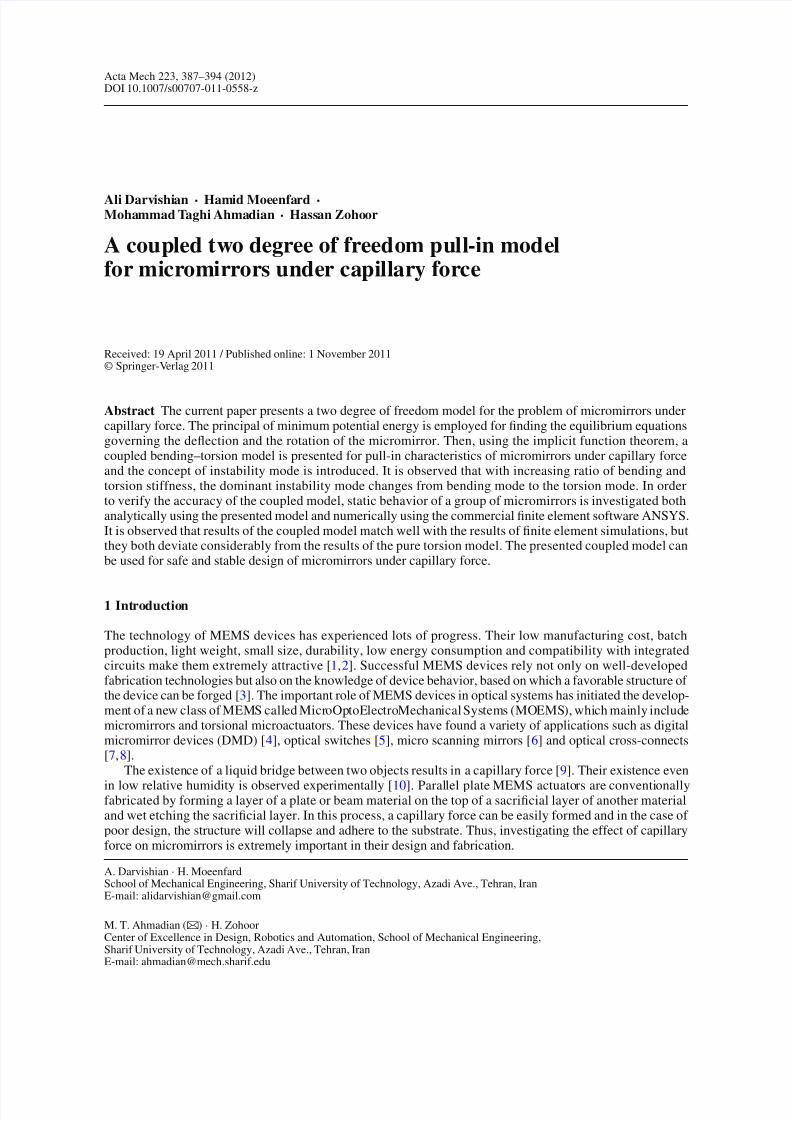
The micromirror shown in Fig. 1 is considered. The capillary pressure underneath the mirror is [13]
PCap =2γ cos θ c
h − z − x θ , (1)
where γ is the surface energy of the liquid, θ c is the contact angle between liquid and solid surface, h isthe initial distance between the mirror and the underneath substrate, z is the vertical deflection of the torsionbeams, and θ is the rotation angle of the mirror. Capillary pressure can be expressed in terms of dimensionlessvariables in the following manner:
PCap =h
WL.
η
1 − −x L
, (2)
where η = 2γ cos θ cWL/h2 is called instability number, and W and L are the width and length of the mi-cromirror, respectively, and = z/h and = θ/θ 0 are normalized parameters with respect to h and themaximum physically possible rotation angle θ 0 = h/ L of the micromirror.
θ
Liquid
x
ξ
dx x θ
1l
2l
C a pdF
z
h
cθ
w
W
L
x
yl
t
Fig. 1 Schematic view of a micromirror under the effect of capillary force
7/30/2019 A coupled two degree of freedom pull-in model for micromirrors under capillary force
http://slidepdf.com/reader/full/a-coupled-two-degree-of-freedom-pull-in-model-for-micromirrors-under-capillary 3/8
A coupled two degree of freedom pull-in model 389
The differential capillary force applied to a differential surface area W d x of the mirror shown in Fig. 1 canbe calculated from the capillary pressure as:
dF Cap = PCapW d x =h
L
η
1 − −x
L
d x . (3)
The total external work done on the micromirror by the capillary force is:
W e =
dF Capdξ, (4)
where ξ = z + x θ is a position parameter shown in Fig. 1. Using Eq. (3) and dξ = d z + x dθ for a givenelement position x , i.e., d x = 0, in Eq. (4) gives
W e =1
2η, (5)
where
(, ) =2h2
L
l2
l1
⎛⎝
0
1
1 − −x L
d
+
0
1
1 − −x L
1
L x d⎞⎠
d x
= 2h2
⎛⎝
0
− ln1−
−β1−−α
d
+
0
− (β − α) + (− 1) ln1−−β
1−−α
2d
⎞⎠ . (6)
In Eq. (6), l1 and l2 are the start and end point of the capillary bridge underneath the mirror as illustrated inFig. 1, and α = l1/ L and β = l2/ L are the normalized values of l1 and l2, respectively. The potential energystored in the torsion beams due to the rotation θ and deflection z is
U =1
2S 0θ 2 +
1
2K 0 z
2=
1
2S 0θ 20 2
+1
2K 0h
22, (7)
where S 0 and K 0 are the overall torsional and vertical stiffness of the two torsion beams and can be calculatedfrom the length l of each torsion beam, the shear modulus G and Young’s modulus E , the polar moment of inertia I p and the second moment of inertia I b of the beam’s cross-section as
S 0 =2GI p
l, K 0 =
24 E I b
l3. (8)
For beams with rectangular cross-section, I b and I p can be computed according to [18]:
I b =1
12wt 3, I p =
1
3t w3
−64
π 5w4
∞n=1
1
(2n − 1)5tanh
(2n − 1) π t
2w, (9)
where t and w are the length and width of the beam’s cross-section, respectively. The total potential energy[19] of the system is:
= U −W e. (10)
At equilibrium state, the variation of vanishes, i.e.,
δ =∂
∂δ +
∂
∂δ = 0. (11)
With arbitrary variations δ and δ for the independent deflection and rotation variables, one finds withEqs. (5) and (10) the following equilibrium equations:
T 1(,) =∂
∂=
∂U
∂−
1
2η
∂
∂= 0, (12)
T 2(,) =∂
∂=
∂U
∂−
1
2η
∂
∂= 0. (13)
7/30/2019 A coupled two degree of freedom pull-in model for micromirrors under capillary force
http://slidepdf.com/reader/full/a-coupled-two-degree-of-freedom-pull-in-model-for-micromirrors-under-capillary 4/8
390 A. Darvishian et al.
Substituting Eqs. (6) and (7) into the equilibrium conditions (12) and (13) yields
T 1(, )/h2= K t +
η
β − α +
1 −
ln
1 − − β
1 − − α
= 0, (14)
T 2 (, )/h2= K b +
η
ln
1 − − β
1 − − α
= 0, (15)
where K t = S 0/ L2, K b = K 0.
With increasing values of η, the values of and are increased. At the pull-in state, η has its maximumvalue. Applying the implicit function theorem [20,21] to Eqs. (14) and (15), a unique solution (η) and (η)gets lost, i.e., the pull-in state is reached, when the determinant
∂T 1
∂∂T 1
∂
∂T 2∂
∂T 2∂
= 0. (16)
Applied to Eqs. (14), (15) and after eliminating η, the following equations for the pull-in state are obtained:
ln
1 − p − β p
1 − p − α p
−ϒ
p
p
β − α +
1 − p
p
ln
1 − p − β p
1 − p − α p
= 0, (17)
3(1 − p)
p
ln
1 − p − β p
1 − p − α p
−
(1 − p)2(α − β)
(1 − p − α p)(1 − p − β p)− 2(α − β)
ln
1 − p − β p
1 − p − α p
+
p p(α − β)
(1 − p − α p)(1 − p − p)
(18)
− p p
(1 − p)(α − β)
(1 − p − α p)(1 − p − β p)−
1
p
ln
1 − p − β p
1 − p − α p
2
= 0,
where ϒ =
K b/K t is a parameter characterizing the stiffness ratio of bending and torsion. The value of η atthe pull-in state
P , p
is calculated from Eq. (13) as
ηP = 2
∂U ∂
∂∂
( p, p)
=K t ϒPP
ln
1− p−α p
1− p−β p
. (19)
It will be shown later that for small ϒ , i.e., bending stiffness is less effective than torsion stiffness, the dominantinstability mode of the micromirror will be the bending mode, otherwise the dominant instability mode willbe the torsion mode.
2.2 Pure torsion model
If bending of the torsion beams is not considered in the formulation, i.e., = z/h = 0, the total potentialenergy (10) is only a function of and the equilibrium equation can formally be obtained by setting equalto zero in Eq. (14):
T 1()/h2K t
= +
η
β − α +
1
ln
1 − β
1 − α
= 0, (20)
where η = η/K t . The pull-in condition is then reduced to
dη
d= 0. (21)
7/30/2019 A coupled two degree of freedom pull-in model for micromirrors under capillary force
http://slidepdf.com/reader/full/a-coupled-two-degree-of-freedom-pull-in-model-for-micromirrors-under-capillary 5/8
A coupled two degree of freedom pull-in model 391
0 20 40 60 80 1000.45
0.5
0.55
0.6
0.65
0.7
0.75
0.8
ϒ
Θ p
Pure torsion model
Coupled model
0 20 40 60 80 1000
0.05
0.1
0.15
0.2
0.25
0.3
Δ p
Pure torsion model
Coupled model
ϒ
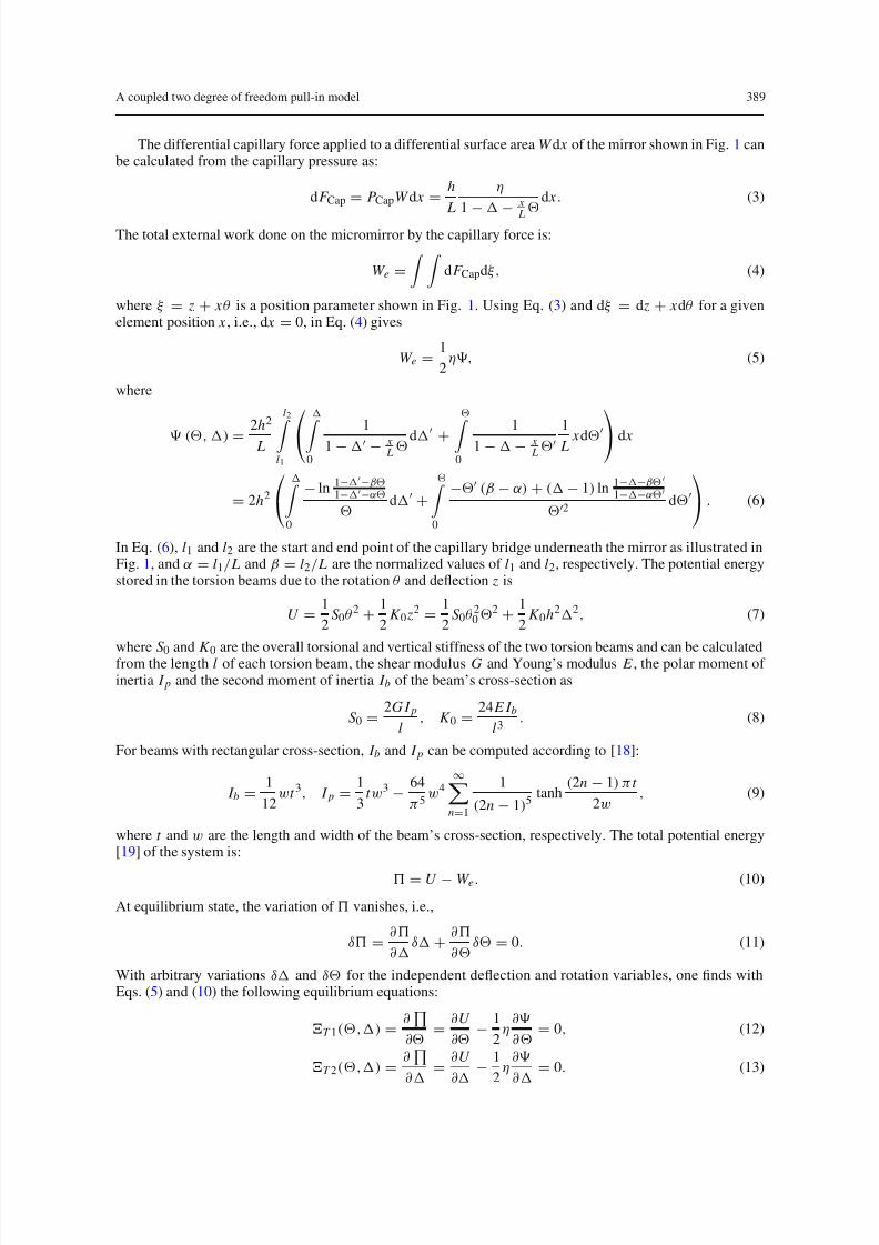
Fig. 2 Dependency of the normalized pull-in angle P and pull-in displacement P of the micromirror on ϒ at α=
0.2and β = 0.8
0 10 20 30 40 50 60 70 80 90 100
0.7
0.8
0.9
1
1.1
1.2
1.3
1.4
ϒ
η p
′
=η p
/ K t
Pure torsion model
Coupled model
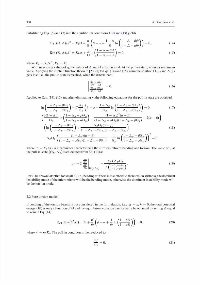
Fig. 3 Values of η = η/K t at the pull-in point against ϒ at α = 0.2 and β = 0.8
3 Results and discussion
Figure 2 shows the dependency of the normalized pull-in angle P and normalized pull-in displacement p
of the micromirror versus ϒ for α = 0.2 and β = 0.8. It is observed that with increasing values of ϒ , thevalue of P asymptotically approaches the value of the pull-in angle predicted by the torsion model and thevalue of P asymptotically approaches 0. Thus, for low values of ϒ , the torsion model deviates considerablyfrom the bending model; that is why neglecting the bending effect leads to significant errors in predicting thepull-in angle
Pof the mirror.
In Fig. 3, the values of the normalized instability number η = η/K t at the pull-in point are plotted againstϒ for both torsion and coupled model at α = 0.2 and β = 0.8. This figure implicitly indicates that at smallvalues of ϒ , the predicted value η of the torsion model is significantly higher than that of the coupled model,and thus the torsion model overestimates the instability limits of the mirror; its related results cannot be trustedfor a safe and stable design.
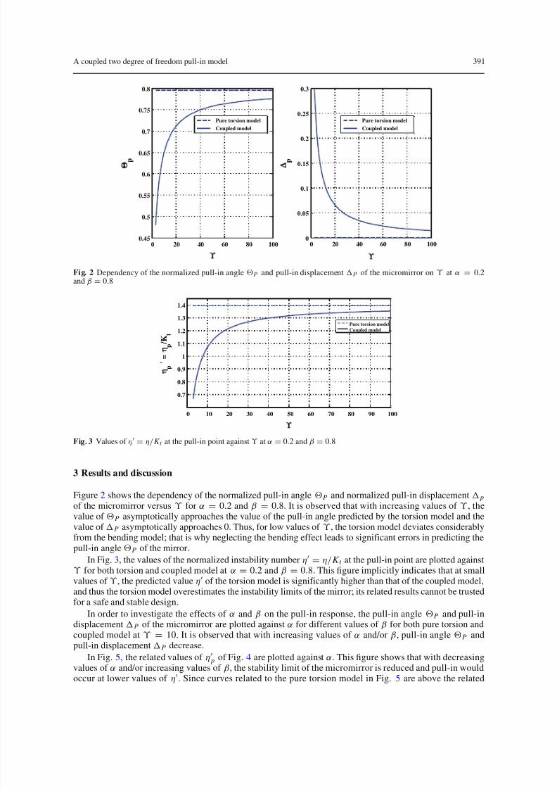
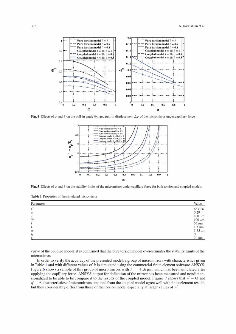
In order to investigate the effects of α and β on the pull-in response, the pull-in angle P and pull-indisplacement P of the micromirror are plotted against α for different values of β for both pure torsion andcoupled model at ϒ = 10. It is observed that with increasing values of α and/or β, pull-in angle P andpull-in displacement P decrease.
In Fig. 5, the related values of η p of Fig. 4 are plotted against α. This figure shows that with decreasingvalues of α and/or increasing values of β, the stability limit of the micromirror is reduced and pull-in wouldoccur at lower values of η. Since curves related to the pure torsion model in Fig. 5 are above the related
7/30/2019 A coupled two degree of freedom pull-in model for micromirrors under capillary force
http://slidepdf.com/reader/full/a-coupled-two-degree-of-freedom-pull-in-model-for-micromirrors-under-capillary 6/8
392 A. Darvishian et al.
0 0.2 0.4 0.6 0.8 10.4
0.5
0.6
0.7
0.8
0.9
1
α
Θ p
Pure torsion model β = 1
Pure torsion model β = 0.9
Pure torsion model β = 0.8
Coupled model ϒ = 10, β = 1
Coupled model ϒ = 10, β = 0.9
Coupled model ϒ = 10, β = 0.8
0 0.2 0.4 0.6 0.8 10
0.02
0.04
0.06
0.08
0.1
0.12
0.14
0.16
0.18
0.2
α
Δ p
Pure torsion model β = 1
Pure torsion model β = 0.9
Pure torsion model β = 0.8Coupled model ϒ = 10, β = 1
Coupled model ϒ = 10, β = 0.9
Coupled model ϒ = 10, β = 0.8
Fig. 4 Effects of α and β on the pull-in angle p and pull-in displacement P of the micromirror under capillary force
0 0.1 0.2 0.3 0.4 0.5 0.6 0.7 0.8 0.9 1
0.5
1
1.5
2
2.5
3
α
η p ′
=η p
/ K t
Pure torsion model β = 1
Pure torsion model β = 0.9
Pure torsion model β = 0.8Coupled model ϒ = 10, β = 1
Coupled model ϒ = 10, β = 0.9
Coupled model ϒ = 10, β = 0.8
Fig. 5 Effects of α and β on the stability limits of the micromirror under capillary force for both torsion and coupled models
Table 1 Properties of the simulated micromirror
Parameter Value
G 66 GPaυ 0.29 L 100 µ mW 100 µ ml 65 µ mt 1.5 µ mw 1.55 µ m
l1 0l2 70 µ m
curve of the coupled model, it is confirmed that the pure torsion model overestimates the stability limits of themicromirror.
In order to verify the accuracy of the presented model, a group of micromirrors with characteristics givenin Table 1 and with different values of h is simulated using the commercial finite element software ANSYS.Figure 6 shows a sample of this group of micromirrors with h = 41.6 µ m, which has been simulated afterapplying the capillary force. ANSYS output for deflection of the mirror has been measured and nondimen-sionalized to be able to be compare it to the results of the coupled model. Figure 7 shows that η − andη− characteristics of micromirrors obtained from the coupled model agree well with finite element results,but they considerably differ from those of the torsion model especially at larger values of η.

7/30/2019 A coupled two degree of freedom pull-in model for micromirrors under capillary force
http://slidepdf.com/reader/full/a-coupled-two-degree-of-freedom-pull-in-model-for-micromirrors-under-capillary 7/8
A coupled two degree of freedom pull-in model 393
Fig. 6 a Meshed configuration of a micromirror with characteristics given in Table 1 and with h = 41.6 µ m. b Deformedconfiguration of the micromirror shown in Fig. 6a under capillary force
0 0.5 1 1.5 2 2.5
0
0.1
0.2
0.3
0.4
0.5
0.6
0.7
0.8
0.9
η′ = η /Kt
Θ
Coupled model
Pure torsion model
FEM model
0 0.5 1 1.5 2
0
0.01
0.02
0.03
0.04
0.05
0.06
0.07
0.08
0.09
0.1
η′ = η /Kt
Δ
Coupled model
FEM model
α = 0 β = 0.7α = 0 β = 0.7
Fig. 7 Equilibrium point of the micromirror shown in Fig. 1 and properties given in Table 1, comparison of the FEM results withthe results of the coupled and pure torsion model
4 Conclusion
In the current paper, the effect of bending of the supporting torsion microbeams on the stability limits of micromirrors under capillary force is investigated. The results show that when the bending stiffness isrelatively small, the dominant instability mode is the bending mode and under this condition, the torsionmodel significantly overestimates the stability limits of the micromirror. Furthermore, it is observed that themicromirror response to the capillary force is highly dependent on the bending stiffness of the torsion micro-beams, and the presented model is capable of capturing this dependency. Finally, the accuracy of the presentedcoupled model is verified by comparing its results with finite element results obtained from ANSYS. Resultsof this paper can be used for a safe, accurate and stable design of micromirrors under wet-etching processwhere capillary force plays a major role in the fabrication.
Acknowledgments The authors wish to gratefullyacknowledge the nameless reviewer for his/heruseful comments on thispaper.Comparison of the results of the coupled model with the results of an FEM model was his/her suggestion.

7/30/2019 A coupled two degree of freedom pull-in model for micromirrors under capillary force
http://slidepdf.com/reader/full/a-coupled-two-degree-of-freedom-pull-in-model-for-micromirrors-under-capillary 8/8
394 A. Darvishian et al.
References
1. Maluf,N., Williams,K.: An Introductionto Microelectromechanical Systems Engineering,2nd edn.MicroelectromechanicalSystems (MEMS) Series. Artech House Inc., Boston (1999)
2. Younis, M.I.: Modeling and simulation of microelectromechanical systems in multi-physics fields. Dissertation submitted
to the Faculty of the Virginia Polytechnic Institute and State University in partial fulfillment of the requirements for thedegree of Doctor of Philosophy in Engineering Mechanics
3. Chao, P.C.P, Chiu, C.W., Tsai, C.Y.: A novel method to predict the pull-in voltage in a closed form for micro-plates actuatedby a distributed electrostatic force. J. Micromech. Microeng. 16, 986–998 (2006)
4. Hornbeck, L.J.: Spatial light modulator and method. US Patent 5,061,049 (1991)5. Ford, J.E., Aksyuk, V.A., Bishop, D.J., Walker, J.A.: Wavelength add-drop swiching using tilting micromirrors. J. Lightwave
Technol. 17, 904–911 (1999)6. Dickensheets, D.L., Kino, G.S.: Silicon-micromachined scanning confocal optical microscope. J. Microelectromech.
Syst. 7(1), 38–47 (1998)7. Zavracky, P.M., Majumber, S., McGruer, E.: Micromechanical switches fabricated using nickel surface micromachining.
J. Microelectromech. Syst. 6, 3–9 (1997)8. Toshiyoshi, H., Fujita, H.: Electrostatic micro torsion mirrors for an optical switch matrix. J. Microelectromech. Syst. 5,
231–237 (1996)9. Wei, Z., Zhao, Y.P.: Growth of liquid bridge in AFM. J. Phys. D Appl. Phys. 40(14), 4368–4375 (2007)
10. Van Zwol, P.J., Palasantzas, G., De Hosson, J.Th.M.: Influence of roughness on capillary forces between hydrophilicsurfaces. Phys. Rev. E 78, 03160 (2008)
11. Mastrangelo, C.H., Hsu, C.H.: Mechanical stability and adhesion of microstructures under capillary forces-part I: basictheory. J. Microelectromech. Syst. 2(1), 33–43 (1993)12. Mastrangelo, C.H., Hsu, C.H.: Mechanical stability and adhesion of microstructures under capillary forces-part 2: experi-
ments. J. Microelectromech. Syst. 2(1), 44–55 (1993)13. Moeenfard, H., Kahrobaiyan, M.H., Ahmadian, M.T.: Aplication of the extended Kantorovich method to the static deflec-
tion of microplates under capillary force. In: ASME International Mechanical Engineering Congress and Exposition,IMECE2010-39517 (2010)
14. Zitzler, L., Herminghaus, S., Mugele, F.: Capillary forces in tapping mode atomic force microscopy. Phys. Rev.B 66, 155436 (2002)
15. Li, X., Peng, Y.: Investigation of capillary adhesion between the microcantilever and the substrate with electronic specklepattern interferometry. Appl. Phys. Lett. 89, 234104 (2006)
16. Jang, J., Schatz, G.C., Ratner, M.A.: Capillary force in atomic force microscopy. J. Chem. Phys. 120(3), 1157–1160 (2004)17. Guo, J.G., Zhou, L.J., Zhao, Y.P.: Instability analysis of torsional MEMS/NEMS actuators under capillary force. J. Colloid
Interface Sci. 331(2), 458–462 (2009)18. Huang, J.-M., Liu, A.Q., Deng, Z.L., Zhang, Q.X., Ahn, J., Asundi, A.: An approach to the coupling effect between torsion
and bending for electrostatic torsional micromirrors. J. Sens. Actuators A 115, 159–167 (2004)
19. Rao, S.S.: Vibration of Continuous Systems. Wiley, New Jersey (2007)20. Bochobza-Degani, O., Nemirovsky, Y.: Modeling the pull-in parameters of electrostatic actuators with a novel lumped twodegree of freedom pull-in model. Sens. Actuator A 97–98, 569–578 (2002)
21. Bochobza-Degani, O., Nemirovsky, Y.: Erratum to “Modeling the pull-in parameters of electrostatic actuators with a novellumped two degrees of freedom pull-in model [Sensors and Actuators A97–98: 569–578]”, Sens. Actuators A 101, 392(2002)