a coordinated control for photovoltaic generators and
TRANSCRIPT
energies
Article
A Coordinated Control for Photovoltaic Generatorsand Energy Storages in Low-Voltage AC/DC HybridMicrogrids under Islanded Mode
Yao Liu 1, Xiaochao Hou 2,*, Xiaofeng Wang 1, Chao Lin 1 and Josep M. Guerrero 3
1 Zhuhai Power Supply Bureau of Guangdong Power Grid Corporation, Zhuhai 519000, China;[email protected] (Y.L.); [email protected] (X.W.); [email protected] (C.L.)
2 School of Information Science and Engineering, Central South University, Changsha 410083, China3 Department of Energy Technology, Aalborg University, Aalborg East DK-9220, Denmark; [email protected]* Correspondence: [email protected]; Tel.: +86-153-8803-4698
Academic Editor: G.J.M. (Gerard) SmitReceived: 30 May 2016; Accepted: 10 August 2016; Published: 17 August 2016
Abstract: The increasing penetration of renewable generators can be a significant challenge due tothe fluctuation of their power generation. Energy storage (ES) units are one solution to improvepower supply quality and guarantee system stability. In this paper, a hybrid microgrid is builtbased on photovoltaic (PV) generator and ES; and coordinated control is proposed and developed toachieve power management in a decentralized manner. This control scheme contains three differentdroop strategies according to characteristics of PV and ES. First, the modified droop control isproposed for PV, which can take full utilization of renewable energy and avoid regulating outputactive power frequently. Second, to maintain the direct current (DC) bus voltage stability, a noveldroop control incorporating a constant power band is presented for DC-side ES. Third, a cascadedroop control is designed for alternating current (AC)-side ES. Thus, the ES lifetime is prolonged.Moreover, interlinking converters (ICs) provide a bridge between AC/DC buses in a hybrid microgrid.The power control of IC is enabled when the AC- or DC-side suffer from active power demandshortage. In particular, if the AC microgrid does not satisfy the reactive power demand, IC then actsas a static synchronous compensator (STATCOM). The effectiveness of the proposed strategies isverified by simulations.
Keywords: coordinated power control; droop control; hybrid microgrid; interlinking converters (ICs);static synchronous compensator (STATCOM)
1. Introduction
Recently, distributed generation (DG) has attracted more attention due to the perceivedadvantages of easy integration of resources, high energy utilization efficiency, flexible installationlocation, and low power transmission losses [1,2]. Therefore, DG penetration in the main grid hasgradually increased, and may potentially be a future trend in electric power system development [3].
As an effective carrier of distributed energy, a microgrid consists of various DG units, energystorage (ES) devices, energy conversion devices, protections, and load monitoring devices. These DGunits always possess a higher degree of controllability and operability compared to conventionalgenerators [4–6]. Resulting from these features, a microgrid could play a critical role in maintainingthe stability of the electrical networks [7–9]. Among various DGs, photovoltaic (PV) generator hasemerged as major DG source in power grids [10].
The power supply quality of an alternating current (AC) microgrid is significantly influencedby intermittence and fluctuation of the distributed power. Moreover, a number of AC-distributed
Energies 2016, 9, 651; doi:10.3390/en9080651 www.mdpi.com/journal/energies

Energies 2016, 9, 651 2 of 15
resources are connected to the microgrid through a multi-stage conversion controller, which lowersthe system efficiency to some extent [11–15]. As an alternative to an AC microgrid, a direct current(DC) distribution microgrid has several attractive features and is developed in [16,17]. First, the DCmicrogrid allows easier integration of DGs, requiring lower conversion stages. Second, the powerquality is enhanced as the harmonic distortion and synchronization issues are inherently eliminated.Especially, the complexity of its control system is greatly reduced when compared with the ACsystem. The DC microgrid has a low installation and operation cost. However, DC microgrid hasa potential disadvantage in that it is not suitable for the rural low voltage networks due to their largeline resistance.
For a DC microgrid powered by PV generator and battery, the AC adaptors of common portableelectronic devices could work properly through reasonable selection of control parameters. However,for a single AC or DC microgrid, a multistage conversion is needed due to the different AC/DCtypes of DGs and loads. The complexity is increased and the efficiency is reduced. To facilitate theintegration of AC- and DC-type loads, hybrid AC/DC microgrid architecture has been extensivelyinvestigated [18–23]. On one hand, the DC and AC type loads are directly fed by the DC- and AC-sidemicrogrid, respectively. On the other hand, the interlinking converter (IC) provides bidirectional energytransfer between the DC and AC subgrids, depending on their individual supply demand conditions.Meanwhile, the plug-and-play function is realized by controlling the power electronic converters.
This paper focuses on power control strategies of a hybrid microgrid in islanded mode. In a previousstudy, the master-slave control method is adopted in [24], which requires the communication betweenthe master and slave controller. The master node is still a single point-of-failure. There have beensome other power flow management methods based on communication [25,26]. In [25], a centralizedcontroller is proposed to generate a compensation signal of primary layer. Thus, an accurate andoptimized power exchange between two subgrids is provided. In [26], a three-level hierarchical controlfor parallel ICs between AC bus and DC bus in a hybrid microgrid is presented. The bus voltagedeviation caused by the droop control in the primary control level is restored, and proportional currentsharing is accomplished. However, the external communication would increase the investment costand reduce reliability and expandability of the system.
To overcome this drawback, decentralized control strategies without communication arepreferable. Autonomous operation of a hybrid microgrid is investigated in [15] and extended in [20,27].Firstly, reference [15] proposes a droop control strategy for controlling the ICs by a normalizedbidirectional droop scheme. Proportional active power sharing can be enforced based on ratings.However, the principle proposed in [15] causes the continuous action of IC during any slip DG orload power variations, leading to more power loss. In [27], an ES system is linked to the DC terminalof the IC, and proper charging and discharging of ES is demonstrated. In [20], an efficient powerflow control scheme is presented for hybrid microgrid with progressive energy flow tuning. It allowsenergy flow across the IC only when one subgrid is over-loaded and the other subgrid is light-loaded.Moreover, reference [28] proposes a fully decentralized control to achieve local power sharing (LPS)in an individual AC or DC network, global power sharing (GPS) throughout AC/DC networksand storage power sharing (SPS). The intended outcome is to activate as few power converters aspossible, in order to avoid their operating losses. Although the various conditions are well designed,the associated mode switching among LPS, GPS, and SPS is slightly complex and easy to lose stability.Moreover, it should not be ignored that both the AC- and DC-distributed generators are treated asideal power source, which does not consider the characteristics of DGs in [15,20,27,28].
There are also some models and control methods that involve integrating the actual distributedresources. Typically, a model of a hybrid microgrid is studied in [29] based on the Wind-PV-ES units.The equivalent circuit of the whole system is developed in both isolated and grid tied modes. However,the operating principle of an IC is not practical to coordinate both of the subgrids. References [30–32]propose a control strategy of Vg/VDC droop and P/VDC anti-droop control strategy for PV panels.It avoids frequent energy fluctuation and improves the quality of output voltage, but does not take
Energies 2016, 9, 651 3 of 15
into account the coordination control of multiple DG units. For the optimal operation of hybridmicrogrid [33,34], a simple algorithm is developed to determine the required sizing of generating unitsand the associated storage capacity in [33]. However, it requires the state of charge information of thebattery in real-time.
In this paper, a coordinated power control paradigm is proposed in a hybrid microgrid byconsidering the characteristics of DG units and designing the effective principle of an IC. The potentialadvantages are summarized below:
(1) Power flow control is realized in a fully decentralized manner.(2) To harness the maximum power of PV units, a modified droop control is proposed.(3) To prolong the lifetime of ES, a novel droop control incorporating a constant power band
is presented.(4) To improve the system efficiency, an effective principle of an IC is developed to coordinate both
AC and DC subgrid microgrids.
This paper is organized as follows: in Section 2, this work starts with a hybrid microgridarchitecture based on PV and ES. In Section 3, the VDC/VAC droop control strategy and its combinationwith P/VDC droop control are presented, as well as their characteristics. Then, the strategy of the IC isintroduced in Section 4. Simulation results with these control principles are shown and discussed inSection 5. Finally, Section 6 presents the conclusions.
2. System Structure
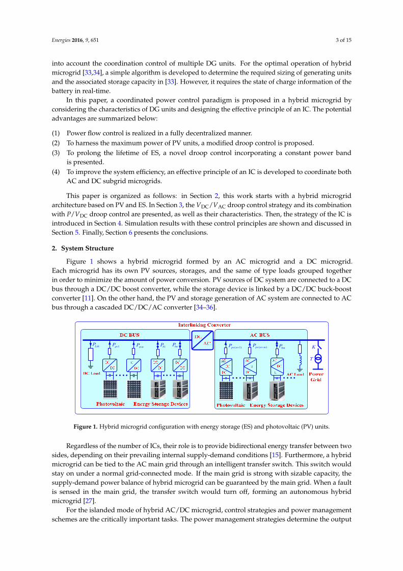
Figure 1 shows a hybrid microgrid formed by an AC microgrid and a DC microgrid.Each microgrid has its own PV sources, storages, and the same of type loads grouped togetherin order to minimize the amount of power conversion. PV sources of DC system are connected to a DCbus through a DC/DC boost converter, while the storage device is linked by a DC/DC buck-boostconverter [11]. On the other hand, the PV and storage generation of AC system are connected to ACbus through a cascaded DC/DC/AC converter [34–36].
Energies 2016, 9, 651 3 of 15
generating units and the associated storage capacity in [33]. However, it requires the state of charge
information of the battery in real‐time.
In this paper, a coordinated power control paradigm is proposed in a hybrid microgrid by
considering the characteristics of DG units and designing the effective principle of an IC. The
potential advantages are summarized below:
(1) Power flow control is realized in a fully decentralized manner.
(2) To harness the maximum power of PV units, a modified droop control is proposed.
(3) To prolong the lifetime of ES, a novel droop control incorporating a constant power band
is presented.
(4) To improve the system efficiency, an effective principle of an IC is developed to coordinate both
AC and DC subgrid microgrids.
This paper is organized as follows: in Section 2, this work starts with a hybrid microgrid
architecture based on PV and ES. In Section 3, the VDC/VAC droop control strategy and its combination
with P/VDC droop control are presented, as well as their characteristics. Then, the strategy of the IC is
introduced in Section 4. Simulation results with these control principles are shown and discussed in
Section 5. Finally, Section 6 presents the conclusions.
2. System Structure
Figure 1 shows a hybrid microgrid formed by an AC microgrid and a DC microgrid. Each
microgrid has its own PV sources, storages, and the same of type loads grouped together in order to
minimize the amount of power conversion. PV sources of DC system are connected to a DC bus
through a DC/DC boost converter, while the storage device is linked by a DC/DC buck‐boost
converter [11]. On the other hand, the PV and storage generation of AC system are connected to AC
bus through a cascaded DC/DC/AC converter [34–36].
1pvP pvnP 1bP bnPLdcP ( 1)pv nP ( )pv n mP
T
KbmP
Figure 1. Hybrid microgrid configuration with energy storage (ES) and photovoltaic (PV) units.
Regardless of the number of ICs, their role is to provide bidirectional energy transfer between
two sides, depending on their prevailing internal supply‐demand conditions [15]. Furthermore, a
hybrid microgrid can be tied to the AC main grid through an intelligent transfer switch. This switch
would stay on under a normal grid‐connected mode. If the main grid is strong with sizable capacity,
the supply‐demand power balance of hybrid microgrid can be guaranteed by the main grid. When a
fault is sensed in the main grid, the transfer switch would turn off, forming an autonomous hybrid
microgrid [27].
For the islanded mode of hybrid AC/DC microgrid, control strategies and power management
schemes are the critically important tasks. The power management strategies determine the output
active and reactive powers of DG and ES units, and control the voltage and frequency at the same
time. Details of the strategies for the different types of DGs and ES units are explained in next section.
Figure 1. Hybrid microgrid configuration with energy storage (ES) and photovoltaic (PV) units.
Regardless of the number of ICs, their role is to provide bidirectional energy transfer between twosides, depending on their prevailing internal supply-demand conditions [15]. Furthermore, a hybridmicrogrid can be tied to the AC main grid through an intelligent transfer switch. This switch wouldstay on under a normal grid-connected mode. If the main grid is strong with sizable capacity, thesupply-demand power balance of hybrid microgrid can be guaranteed by the main grid. When a faultis sensed in the main grid, the transfer switch would turn off, forming an autonomous hybridmicrogrid [27].
For the islanded mode of hybrid AC/DC microgrid, control strategies and power managementschemes are the critically important tasks. The power management strategies determine the output

Energies 2016, 9, 651 4 of 15
active and reactive powers of DG and ES units, and control the voltage and frequency at the same time.Details of the strategies for the different types of DGs and ES units are explained in next section.
3. Proposed Power Control Strategy of Hybrid AC/DC Microgrid
In this Section, a control strategy based on the VDC/VAC droop and its combination with P/VDC
droop control method is proposed for power management. Then, the control structures of PVs and ESunits are discussed in details.
3.1. VDC/VAC Droop Control (Droop-1)
The VDC/VAC droop control principle is based on the specific characteristic of islanded microgrids,which differs significantly from the conventional power system. In a microgrid, the DG unit is generallylinked to the AC bus through the power electronic converter with a DC-side capacitor, as shown inFigure 2.
Energies 2016, 9, 651 4 of 15
3. Proposed Power Control Strategy of Hybrid AC/DC Microgrid
In this Section, a control strategy based on the VDC/VAC droop and its combination with P/VDC
droop control method is proposed for power management. Then, the control structures of PVs and
ES units are discussed in details.
3.1. VDC/VAC Droop Control (Droop‐1)
The VDC/VAC droop control principle is based on the specific characteristic of islanded microgrids,
which differs significantly from the conventional power system. In a microgrid, the DG unit is
generally linked to the AC bus through the power electronic converter with a DC‐side capacitor, as
shown in Figure 2.
C
1s 3s
2s 4s
N
primi dci
P line0V gidcV
fC
fL
load
acV Z R jX
P jQ
Figure 2. Microgrid architecture for one distributed generation (DG).
If the generated power and absorbed power becomes unbalanced, the DC‐side capacitor voltage
VDC of the power sources would change. According to Figure 2, the VDC can be mathematically derived
as follows:
DCprim DC
d
d
VC i i
t (1)
where iprim and iDC present the current of prime sources and input terminal in inverter, respectively.
From Equation (1), VDC is used as the trigger for power changes.
Furthermore, the line parameter of the low voltage microgrid is mainly resistive. Assuming that
the line inductance is neglected, the active and reactive powers from one unit can be expressed as
follows [37]:
2AC cosV V V
PR R
(2)
AC sinV V
QR
(3)
where VAC is the amplitude of the inverter output voltage, V is the common bus voltage, φ is the
power angle, and R is the line resistance. P and Q are the output active and reactive powers of a DG,
respectively.
According to Equation (2), the active power P depends on the voltage amplitude VAC, unlike in
transmission grids where the reactive power is linked with the voltage amplitude [37].
Therefore, the relationship between VDC and VAC can be constructed to change the active power,
which forms the basis of the new VDC/VAC droop control:
AC AC,nom DC DC,nom( )V V m V V (4)
where VAC,nom and VDC,nom are the nominal voltages of the AC‐ and DC‐sides of the power converter,
respectively. Note that a slight change of VAC results in a change of the transmitted energy from DG
to the common bus. m is the slope of the VDC/VAC droop. VAC and VDC are the AC‐ and DC‐side voltages
of the power converter, respectively.
Figure 2. Microgrid architecture for one distributed generation (DG).
If the generated power and absorbed power becomes unbalanced, the DC-side capacitor voltageVDC of the power sources would change. According to Figure 2, the VDC can be mathematicallyderived as follows:
CdVDC
dt= iprim − iDC (1)
where iprim and iDC present the current of prime sources and input terminal in inverter, respectively.From Equation (1), VDC is used as the trigger for power changes.
Furthermore, the line parameter of the low voltage microgrid is mainly resistive. Assuming thatthe line inductance is neglected, the active and reactive powers from one unit can be expressed asfollows [37]:
P =VACV
Rcosφ− V2
R(2)
Q = −VACVR
sinφ (3)
where VAC is the amplitude of the inverter output voltage, V is the common bus voltage, φ is thepower angle, and R is the line resistance. P and Q are the output active and reactive powers ofa DG, respectively.
According to Equation (2), the active power P depends on the voltage amplitude VAC, unlike intransmission grids where the reactive power is linked with the voltage amplitude [37].
Therefore, the relationship between VDC and VAC can be constructed to change the active power,which forms the basis of the new VDC/VAC droop control:
VAC = VAC,nom + m(VDC −VDC,nom) (4)
where VAC,nom and VDC,nom are the nominal voltages of the AC- and DC-sides of the power converter,respectively. Note that a slight change of VAC results in a change of the transmitted energy from DG

Energies 2016, 9, 651 5 of 15
to the common bus. m is the slope of the VDC/VAC droop. VAC and VDC are the AC- and DC-sidevoltages of the power converter, respectively.
The plot illustrating the new VDC/VAC droop control is depicted in Figure 3. With this controller,the microgrid voltage is changed by detecting changes of VDC, and the supply-demand balance isachieved without changing output active power P. Generally, frequent power changes are avoided,and no communication for the primary control is required. The tolerated voltage deviation fromits nominal value is effectively used. Moreover, both controllers take the specific characteristics ofan islanded AC microgrid into account, such as the lack of inertia, resistive lines, and high share ofdistributed generators.
Energies 2016, 9, 651 5 of 15
The plot illustrating the new VDC/VAC droop control is depicted in Figure 3. With this controller,
the microgrid voltage is changed by detecting changes of VDC, and the supply‐demand balance is
achieved without changing output active power P. Generally, frequent power changes are avoided,
and no communication for the primary control is required. The tolerated voltage deviation from its
nominal value is effectively used. Moreover, both controllers take the specific characteristics of an
islanded AC microgrid into account, such as the lack of inertia, resistive lines, and high share of
distributed generators.
( )acV pu
,ac nomV
,dc nomV ( )dcV pu0
0.8 1.2
0.95
1.05
Figure 3. Schematic diagram of the new VDC/VAC droop.
In this AC voltage range (±5%), the DG units are actively dispatched as they operate at maximum
power point tracking (MPPT). This is particularly advantageous for DGs since their energy can be
used more efficiently. According to this rule, a PV generation of the DC‐side in a hybrid microgrid,
which consists of the PV array, DC/DC converter, and local control, should operate in the MPPT
mode based on the perturb and observe (P & O) method [38,39]. On the other hand, the PV generation
system of AC‐side consists of the PV array, cascaded DC/DC/AC converter, output filters, and local
control system. The front‐stage converter adopts the MPPT method, while the second‐stage utilizes
the newly proposed VDC/VAC droop control. The overall control scheme of PV generation of the AC‐
side is shown in Figure 4.
dcs
1D1L LineR
pvC dcC
pvIpvV dcS
1s 3s 5s
2s 4s 6s
LineRacL
acC
acV
dcV
1-6SdcV
,dc nomV
,ac nomV
dV
qV
dIqI
acV
acac
acI
acrefV
0qrefV
acrefV
1s
f
Q
nomQ
nomf
lineI acV
Q
Figure 4. The overall scheme of the alternating current (AC)‐side PV generator in hybrid microgrid.
For reactive power control of PVs in the AC‐side, the Q‐f boost method is adopted by considering
Equation (3) in a low‐voltage hybrid microgrid [37]:
* *( )f f m Q Q (5)
Figure 3. Schematic diagram of the new VDC/VAC droop.
In this AC voltage range (±5%), the DG units are actively dispatched as they operate at maximumpower point tracking (MPPT). This is particularly advantageous for DGs since their energy can beused more efficiently. According to this rule, a PV generation of the DC-side in a hybrid microgrid,which consists of the PV array, DC/DC converter, and local control, should operate in the MPPT modebased on the perturb and observe (P & O) method [38,39]. On the other hand, the PV generationsystem of AC-side consists of the PV array, cascaded DC/DC/AC converter, output filters, and localcontrol system. The front-stage converter adopts the MPPT method, while the second-stage utilizes thenewly proposed VDC/VAC droop control. The overall control scheme of PV generation of the AC-sideis shown in Figure 4.
Energies 2016, 9, 651 5 of 15
The plot illustrating the new VDC/VAC droop control is depicted in Figure 3. With this controller,
the microgrid voltage is changed by detecting changes of VDC, and the supply‐demand balance is
achieved without changing output active power P. Generally, frequent power changes are avoided,
and no communication for the primary control is required. The tolerated voltage deviation from its
nominal value is effectively used. Moreover, both controllers take the specific characteristics of an
islanded AC microgrid into account, such as the lack of inertia, resistive lines, and high share of
distributed generators.
( )acV pu
,ac nomV
,dc nomV ( )dcV pu0
0.8 1.2
0.95
1.05
Figure 3. Schematic diagram of the new VDC/VAC droop.
In this AC voltage range (±5%), the DG units are actively dispatched as they operate at maximum
power point tracking (MPPT). This is particularly advantageous for DGs since their energy can be
used more efficiently. According to this rule, a PV generation of the DC‐side in a hybrid microgrid,
which consists of the PV array, DC/DC converter, and local control, should operate in the MPPT
mode based on the perturb and observe (P & O) method [38,39]. On the other hand, the PV generation
system of AC‐side consists of the PV array, cascaded DC/DC/AC converter, output filters, and local
control system. The front‐stage converter adopts the MPPT method, while the second‐stage utilizes
the newly proposed VDC/VAC droop control. The overall control scheme of PV generation of the AC‐
side is shown in Figure 4.
dcs
1D1L LineR
pvC dcC
pvIpvV dcS
1s 3s 5s
2s 4s 6s
LineRacL
acC
acV
dcV
1-6SdcV
,dc nomV
,ac nomV
dV
qV
dIqI
acV
acac
acI
acrefV
0qrefV
acrefV
1s
f
Q
nomQ
nomf
lineI acV
Q
Figure 4. The overall scheme of the alternating current (AC)‐side PV generator in hybrid microgrid.
For reactive power control of PVs in the AC‐side, the Q‐f boost method is adopted by considering
Equation (3) in a low‐voltage hybrid microgrid [37]:
* *( )f f m Q Q (5)
Figure 4. The overall scheme of the alternating current (AC)-side PV generator in hybrid microgrid.
For reactive power control of PVs in the AC-side, the Q-f boost method is adopted by consideringEquation (3) in a low-voltage hybrid microgrid [37]:
f = f ∗ + m(Q−Q∗) (5)
Energies 2016, 9, 651 6 of 15
where f * represents the frequency reference value at a normal load, m is droop gain, and Q and Q* arethe output reactive power and its normal reference of a DG unit, respectively.
3.2. P/VDC Droop Control (Droop-2)
When the VDC/VAC droop control is adopted, the AC microgrid voltage is allowed to changewithin a certain range. If the load changes dramatically, the DC capacitor voltage will exceed thespecified range, thus deteriorating the public bus voltage of AC microgrid. Hence, a new P/VDC droopcontrol with a constant power band should be proposed. The active power P (or DC current IDC) ischanged according to a droop with the microgrid DC voltage VDC:
VDC = VDC,nom − kp (P− Pnom) (6)
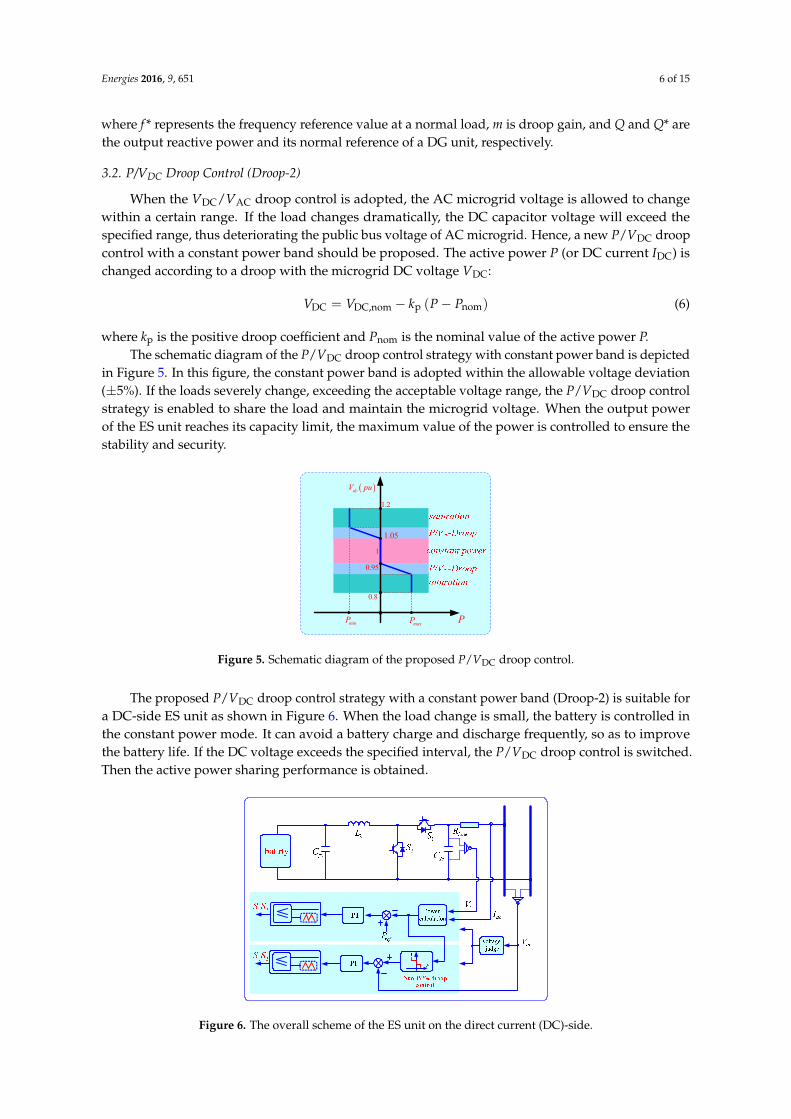
where kp is the positive droop coefficient and Pnom is the nominal value of the active power P.The schematic diagram of the P/VDC droop control strategy with constant power band is depicted
in Figure 5. In this figure, the constant power band is adopted within the allowable voltage deviation(±5%). If the loads severely change, exceeding the acceptable voltage range, the P/VDC droop controlstrategy is enabled to share the load and maintain the microgrid voltage. When the output powerof the ES unit reaches its capacity limit, the maximum value of the power is controlled to ensure thestability and security.
Energies 2016, 9, 651 6 of 15
where f* represents the frequency reference value at a normal load, m is droop gain, and Q and Q*
are the output reactive power and its normal reference of a DG unit, respectively.
3.2. P/VDC Droop Control (Droop‐2)
When the VDC/VAC droop control is adopted, the AC microgrid voltage is allowed to change
within a certain range. If the load changes dramatically, the DC capacitor voltage will exceed the
specified range, thus deteriorating the public bus voltage of AC microgrid. Hence, a new P/VDC droop
control with a constant power band should be proposed. The active power P (or DC current IDC) is
changed according to a droop with the microgrid DC voltage VDC:
DC DC,nom p nomV V k P P (6)
where kp is the positive droop coefficient and Pnom is the nominal value of the active power P.
The schematic diagram of the P/VDC droop control strategy with constant power band is depicted
in Figure 5. In this figure, the constant power band is adopted within the allowable voltage deviation
(±5%). If the loads severely change, exceeding the acceptable voltage range, the P/VDC droop control
strategy is enabled to share the load and maintain the microgrid voltage. When the output power of
the ES unit reaches its capacity limit, the maximum value of the power is controlled to ensure the
stability and security.
dcV pu
P
1
1.05
0.8
1.2
0.95
maxPminP
Figure 5. Schematic diagram of the proposed P/VDC droop control.
The proposed P/VDC droop control strategy with a constant power band (Droop‐2) is suitable for
a DC‐side ES unit as shown in Figure 6. When the load change is small, the battery is controlled in
the constant power mode. It can avoid a battery charge and discharge frequently, so as to improve
the battery life. If the DC voltage exceeds the specified interval, the P/VDC droop control is switched.
Then the active power sharing performance is obtained.
Figure 6. The overall scheme of the ES unit on the direct current (DC)‐side.
Figure 5. Schematic diagram of the proposed P/VDC droop control.
The proposed P/VDC droop control strategy with a constant power band (Droop-2) is suitable fora DC-side ES unit as shown in Figure 6. When the load change is small, the battery is controlled inthe constant power mode. It can avoid a battery charge and discharge frequently, so as to improvethe battery life. If the DC voltage exceeds the specified interval, the P/VDC droop control is switched.Then the active power sharing performance is obtained.
Energies 2016, 9, 651 6 of 15
where f* represents the frequency reference value at a normal load, m is droop gain, and Q and Q*
are the output reactive power and its normal reference of a DG unit, respectively.
3.2. P/VDC Droop Control (Droop‐2)
When the VDC/VAC droop control is adopted, the AC microgrid voltage is allowed to change
within a certain range. If the load changes dramatically, the DC capacitor voltage will exceed the
specified range, thus deteriorating the public bus voltage of AC microgrid. Hence, a new P/VDC droop
control with a constant power band should be proposed. The active power P (or DC current IDC) is
changed according to a droop with the microgrid DC voltage VDC:
DC DC,nom p nomV V k P P (6)
where kp is the positive droop coefficient and Pnom is the nominal value of the active power P.
The schematic diagram of the P/VDC droop control strategy with constant power band is depicted
in Figure 5. In this figure, the constant power band is adopted within the allowable voltage deviation
(±5%). If the loads severely change, exceeding the acceptable voltage range, the P/VDC droop control
strategy is enabled to share the load and maintain the microgrid voltage. When the output power of
the ES unit reaches its capacity limit, the maximum value of the power is controlled to ensure the
stability and security.
dcV pu
P
1
1.05
0.8
1.2
0.95
maxPminP
Figure 5. Schematic diagram of the proposed P/VDC droop control.
The proposed P/VDC droop control strategy with a constant power band (Droop‐2) is suitable for
a DC‐side ES unit as shown in Figure 6. When the load change is small, the battery is controlled in
the constant power mode. It can avoid a battery charge and discharge frequently, so as to improve
the battery life. If the DC voltage exceeds the specified interval, the P/VDC droop control is switched.
Then the active power sharing performance is obtained.
Figure 6. The overall scheme of the ES unit on the direct current (DC)‐side. Figure 6. The overall scheme of the ES unit on the direct current (DC)-side.
Energies 2016, 9, 651 7 of 15
3.3. Combination of VDC/VAC and P/VDC Droop Control (Droop-3)
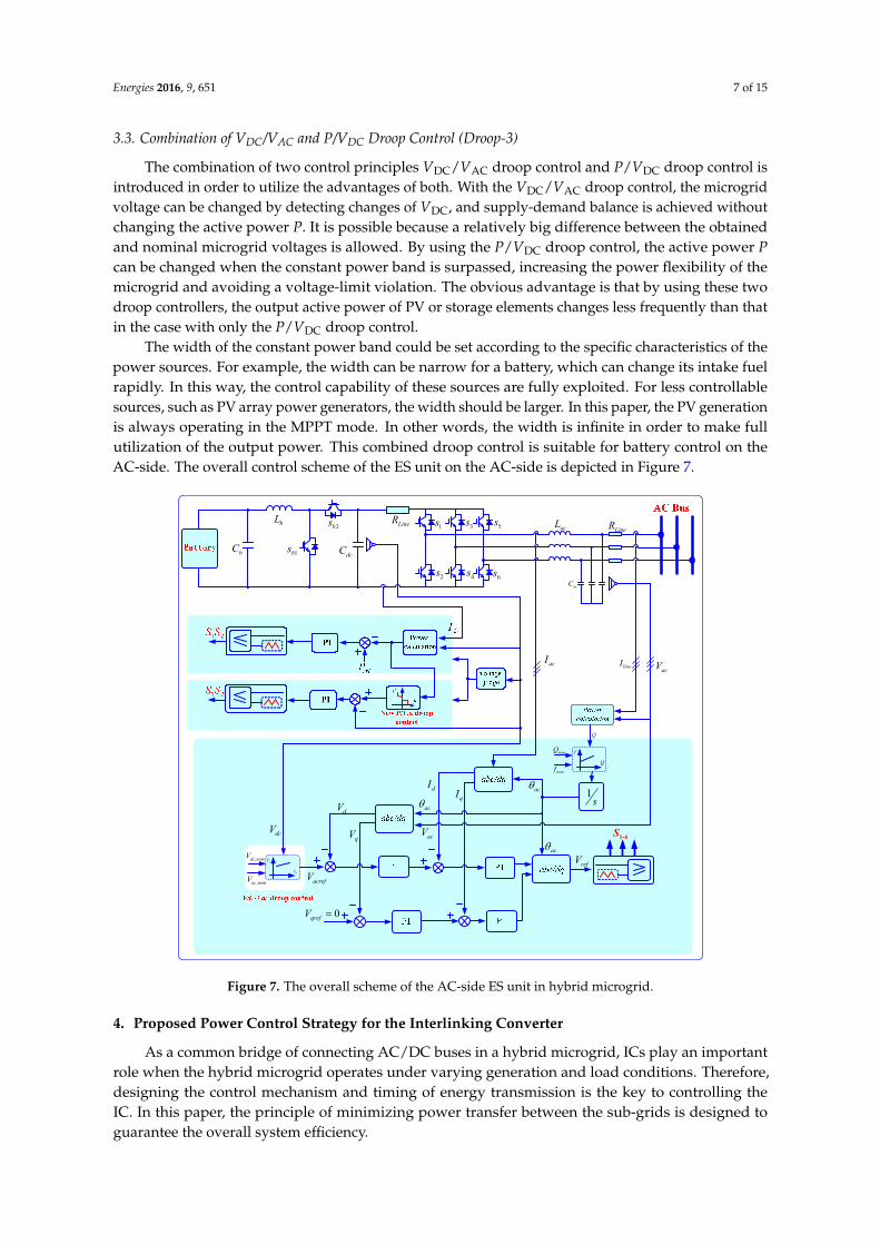
The combination of two control principles VDC/VAC droop control and P/VDC droop control isintroduced in order to utilize the advantages of both. With the VDC/VAC droop control, the microgridvoltage can be changed by detecting changes of VDC, and supply-demand balance is achieved withoutchanging the active power P. It is possible because a relatively big difference between the obtainedand nominal microgrid voltages is allowed. By using the P/VDC droop control, the active power Pcan be changed when the constant power band is surpassed, increasing the power flexibility of themicrogrid and avoiding a voltage-limit violation. The obvious advantage is that by using these twodroop controllers, the output active power of PV or storage elements changes less frequently than thatin the case with only the P/VDC droop control.
The width of the constant power band could be set according to the specific characteristics of thepower sources. For example, the width can be narrow for a battery, which can change its intake fuelrapidly. In this way, the control capability of these sources are fully exploited. For less controllablesources, such as PV array power generators, the width should be larger. In this paper, the PV generationis always operating in the MPPT mode. In other words, the width is infinite in order to make fullutilization of the output power. This combined droop control is suitable for battery control on theAC-side. The overall control scheme of the ES unit on the AC-side is depicted in Figure 7.
Energies 2016, 9, 651 7 of 15
3.3. Combination of VDC/VAC and P/VDC Droop Control (Droop‐3)
The combination of two control principles VDC/VAC droop control and P/VDC droop control is
introduced in order to utilize the advantages of both. With the VDC/VAC droop control, the microgrid
voltage can be changed by detecting changes of VDC, and supply‐demand balance is achieved without
changing the active power P. It is possible because a relatively big difference between the obtained
and nominal microgrid voltages is allowed. By using the P/VDC droop control, the active power P can
be changed when the constant power band is surpassed, increasing the power flexibility of the
microgrid and avoiding a voltage‐limit violation. The obvious advantage is that by using these two
droop controllers, the output active power of PV or storage elements changes less frequently than
that in the case with only the P/VDC droop control.
The width of the constant power band could be set according to the specific characteristics of the
power sources. For example, the width can be narrow for a battery, which can change its intake fuel
rapidly. In this way, the control capability of these sources are fully exploited. For less controllable
sources, such as PV array power generators, the width should be larger. In this paper, the PV
generation is always operating in the MPPT mode. In other words, the width is infinite in order to
make full utilization of the output power. This combined droop control is suitable for battery control
on the AC‐side. The overall control scheme of the ES unit on the AC‐side is depicted in Figure 7.
1bs
bL LineR
bC dcC
1s 3s 5s
2s 4s 6s
LineRacL
acC
acIacV
2bs
acV
dcV
1-6SdcV
,dc nomV
,ac nomV
dV
qV
dIqI
acV
acac
acrefV
0qrefV
acrefV
1s
f
Q
nomQ
nomf
lineI
Q
Figure 7. The overall scheme of the AC‐side ES unit in hybrid microgrid.
4. Proposed Power Control Strategy for the Interlinking Converter
As a common bridge of connecting AC/DC buses in a hybrid microgrid, ICs play an important
role when the hybrid microgrid operates under varying generation and load conditions. Therefore,
designing the control mechanism and timing of energy transmission is the key to controlling the IC.
In this paper, the principle of minimizing power transfer between the sub‐grids is designed to
guarantee the overall system efficiency.
Figure 7. The overall scheme of the AC-side ES unit in hybrid microgrid.
4. Proposed Power Control Strategy for the Interlinking Converter
As a common bridge of connecting AC/DC buses in a hybrid microgrid, ICs play an importantrole when the hybrid microgrid operates under varying generation and load conditions. Therefore,designing the control mechanism and timing of energy transmission is the key to controlling theIC. In this paper, the principle of minimizing power transfer between the sub-grids is designed toguarantee the overall system efficiency.

Energies 2016, 9, 651 8 of 15
If one of the AC/DC sub-grids is capable of providing the load by itself while the other cannotprovide the demanded load fully, the active power control of the IC is activated. On the other hand,another scenario is permissible whereby both sides are capable of individually charging the storageswithout a triggering energy transfer. Therefore, operating losses of the IC are avoided, resulting ina higher overall system efficiency. Regarding the reactive power, if the AC microgrid does not satisfythe reactive power demand, the reactive power control for IC can operate as a static synchronouscompensator (STATCOM) to satisfy the demand. Thus, the Q-f droop control strategy can be appliedin reactive power sharing [37].
To realize the above scenarios physically in mathematical formulations, the appropriate amountof charging power is first determined. When the active power flow of the AC/DC bus exceeds 80% ofthe overall power capacity, the energy transmission indicator G(AC) or G(DC) is set as follows:
G (AC) =
{1 if PAC,max ≥ PAC ≥ 0.8PAC,max
0 otherwise(7)
G (DC) =
{1 if PDC,max ≥ PDC ≥ 0.8PDC,max
0 otherwise(8)
where PAC and PDC are the provided active powers by the AC-side and DC-side, respectively;and PAC,max and PDC,max are the maximum active power demand of the two sides, respectively.Equations (7) and (8) show that because one side has surplus energy, the energy transmission channelbetween the two sides can be opened by the controller setting. So, the energy transmission indicator isset as 1. Otherwise, when one side is not enough, the energy transmission channel is closed. The energytransmission indicator is set as 0.
When one side has surplus energy, the other side cannot provide the load demand fully, the controlmechanism is just activated. Thus, the active power reference of the IC is described as:
Pic,ref =
λDC (PDC − 0.8PDC,max) if G (DC)× G (AC) = 1λAC (PAC − 0.8PAC,max) if G (DC)× G (AC) = 10 otherwise
(9)
where “×”means the logical operator “AND”, λAC and λDC are the AC/DC transmission coefficients,and (PDC − 0.8PDC,max) and (PAC − 0.8PAC,max) indicate the actual power demand shortfall of the DC-and AC-side microgrids, respectively. That is, Equation (9) shows that the IC needs to compare theenergy transmission of both sides, and then the active power Pic,ref can be fixed. In order to ensurethat the active power demand is not more than the maximum output active power on the other side,the AC/DC transmission coefficients λAC and λDC should be chosen as follows: λDC =
0.8PAC,max−PAC
(PDC−0.8PDC,max)+(0.8PAC,max−PAC)
λAC =0.8PDC,max−PDC
(PAC−0.8PAC,max)+(0.8PDC,max−PDC)
(10)
According to Equation (10), if the AC-side is capable of providing the active power demand fullyand has a great surplus, then the DC-side transmission coefficient λDC is given by:
(PDC − 0.8PDC,max) << (0.8PAC,max − PAC) and λDC = 1 (11)
Likewise, the AC-side transmission coefficient λAC is given by:
(PDC − 0.8PDC,max) >> (0.8PAC,max − PAC) and λAC = 1 (12)
where “<<” is the mathematical operator “far less than”. The AC/DC transmission coefficients λAC
and λDC represent the transfer capability. A specific example is used here for further illustration. When
Energies 2016, 9, 651 9 of 15
the DC-side microgrid has 0.9 pu power flow of its maximum active power, the energy transmissionindicator G(DC) would be chosen as 1. Meanwhile, the AC-side microgrid has 0.2 pu power flow ofthe maximum active power (G(AC) = 0). Then, active power control of the IC is activated, and theDC-side transmission coefficient λDC = 0.6PAC,max/(0.1PDC,max + 0.6PAC,max) < 1. Thus, it guaranteesthat the IC power reference Pic,ref = λDC × 0.1PDC,max does not exceed the maximum available power0.6PAC,max from the AC-side microgrid.
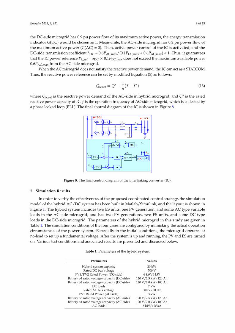
When the AC microgrid does not satisfy the reactive power demand, the IC can act as a STATCOM.Thus, the reactive power reference can be set by modified Equation (5) as follows:
Qic,ref = Q∗ +1n( f − f ∗) (13)
where Qic,ref is the reactive power demand of the AC-side in hybrid microgrid, and Q* is the ratedreactive power capacity of IC. f is the operation frequency of AC-side microgrid, which is collected bya phase locked loop (PLL). The final control diagram of the IC is shown in Figure 8.
Energies 2016, 9, 651 9 of 15
power flow of the maximum active power (G(AC) = 0). Then, active power control of the IC is
activated, and the DC‐side transmission coefficient λDC = 0.6PAC,max/(0.1PDC,max + 0.6PAC,max) < 1. Thus,
it guarantees that the IC power reference Pic,ref = λDC × 0.1PDC,max does not exceed the maximum
available power 0.6PAC,max from the AC‐side microgrid.
When the AC microgrid does not satisfy the reactive power demand, the IC can act as a
STATCOM. Thus, the reactive power reference can be set by modified Equation (5) as follows:
* *AC,ref
1( )Q Q f fn
(13)
where QAC,ref is the reactive power demand of the AC‐side in hybrid microgrid, and Q* is the rated
reactive power capacity of IC. f is the operation frequency of AC‐side microgrid, which is collected
by a phase locked loop (PLL). The final control diagram of the IC is shown in Figure 8.
1s 3s 5s
2s 4s 6s
LineRacL
acC
dq / abc
1-6S
dIqI
,ic refP
ac
acI
acrefV
acVabc / dq
2 3 dV
2 3 dV,ic refQ
dV
Figure 8. The final control diagram of the interlinking converter (IC).
5. Simulation Results
In order to verify the effectiveness of the proposed coordinated control strategy, the simulation
model of the hybrid AC/DC system has been built in Matlab/Simulink, and the layout is shown in
Figure 1. The hybrid system includes two ES units, one PV generation, and some AC type variable
loads in the AC‐side microgrid, and has two PV generations, two ES units, and some DC type loads
in the DC‐side microgrid. The parameters of the hybrid microgrid in this study are given in Table 1.
The simulation conditions of the four cases are configured by mimicking the actual operation
circumstances of the power system. Especially in the initial conditions, the microgrid operates at no‐
load to set up a fundamental voltage. After the system is up and running, the PV and ES are turned
on. Various test conditions and associated results are presented and discussed below.
Table 1. Parameters of the hybrid system.
Parameters Values
Hybrid system capacity 20 kW
Rated DC bus voltage 700 V
PV1/PV2 Rated Power (DC‐side) 6 kW/6 kW
Battery b1 rated voltage/capacity (DC‐side) 120 V/2.5 kW/120 Ah
Battery b2 rated voltage/capacity (DC‐side) 120 V/2.0 kW/100 Ah
DC loads 7 kW
Rated AC bus voltage 380 V/50 Hz
PV1 Rated Power (AC‐side) 3 kW
Battery b3 rated voltage/capacity (AC‐side) 120 V/2.5 kW/120 Ah
Battery b4 rated voltage/capacity (AC‐side) 120 V/2.0 kW/100 Ah
AC loads 5 kW/1 kVar
Figure 8. The final control diagram of the interlinking converter (IC).
5. Simulation Results
In order to verify the effectiveness of the proposed coordinated control strategy, the simulationmodel of the hybrid AC/DC system has been built in Matlab/Simulink, and the layout is shown inFigure 1. The hybrid system includes two ES units, one PV generation, and some AC type variableloads in the AC-side microgrid, and has two PV generations, two ES units, and some DC typeloads in the DC-side microgrid. The parameters of the hybrid microgrid in this study are given inTable 1. The simulation conditions of the four cases are configured by mimicking the actual operationcircumstances of the power system. Especially in the initial conditions, the microgrid operates atno-load to set up a fundamental voltage. After the system is up and running, the PV and ES are turnedon. Various test conditions and associated results are presented and discussed below.
Table 1. Parameters of the hybrid system.
Parameters Values
Hybrid system capacity 20 kWRated DC bus voltage 700 V
PV1/PV2 Rated Power (DC-side) 6 kW/6 kWBattery b1 rated voltage/capacity (DC-side) 120 V/2.5 kW/120 AhBattery b2 rated voltage/capacity (DC-side) 120 V/2.0 kW/100 Ah
DC loads 7 kWRated AC bus voltage 380 V/50 Hz
PV1 Rated Power (AC-side) 3 kWBattery b3 rated voltage/capacity (AC-side) 120 V/2.5 kW/120 AhBattery b4 rated voltage/capacity (AC-side) 120 V/2.0 kW/100 Ah
AC loads 5 kW/1 kVar
Energies 2016, 9, 651 10 of 15
5.1. Case 1: Test of the Proposed Droop-1 Control Strategy for Photovoltaic
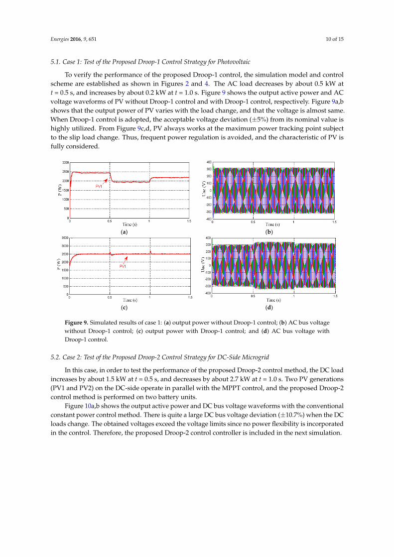
To verify the performance of the proposed Droop-1 control, the simulation model and controlscheme are established as shown in Figures 2 and 4. The AC load decreases by about 0.5 kW att = 0.5 s, and increases by about 0.2 kW at t = 1.0 s. Figure 9 shows the output active power and ACvoltage waveforms of PV without Droop-1 control and with Droop-1 control, respectively. Figure 9a,bshows that the output power of PV varies with the load change, and that the voltage is almost same.When Droop-1 control is adopted, the acceptable voltage deviation (±5%) from its nominal value ishighly utilized. From Figure 9c,d, PV always works at the maximum power tracking point subjectto the slip load change. Thus, frequent power regulation is avoided, and the characteristic of PV isfully considered.
Energies 2016, 9, 651 10 of 15
5.1. Case 1: Test of the Proposed Droop‐1 Control Strategy for Photovoltaic
To verify the performance of the proposed Droop‐1 control, the simulation model and control
scheme are established as shown in Figures 2 and 4. The AC load decreases by about 0.5 kW at t = 0.5
s, and increases by about 0.2 kW at t = 1.0 s. Figure 9 shows the output active power and AC voltage
waveforms of PV without Droop‐1 control and with Droop‐1 control, respectively. Figure 9a,b shows
that the output power of PV varies with the load change, and that the voltage is almost same. When
Droop‐1 control is adopted, the acceptable voltage deviation (±5%) from its nominal value is highly
utilized. From Figure 9c,d, PV always works at the maximum power tracking point subject to the slip
load change. Thus, frequent power regulation is avoided, and the characteristic of PV is fully considered.
(a) (b)
(c) (d)
Figure 9. Simulated results of case 1: (a) output power without Droop‐1 control; (b) AC bus voltage
without Droop‐1 control; (c) output power with Droop‐1 control; and (d) AC bus voltage with
Droop‐1 control.
5.2. Case 2: Test of the Proposed Droop‐2 Control Strategy for DC‐Side Microgrid
In this case, in order to test the performance of the proposed Droop‐2 control method, the DC
load increases by about 1.5 kW at t = 0.5 s, and decreases by about 2.7 kW at t = 1.0 s. Two PV
generations (PV1 and PV2) on the DC‐side operate in parallel with the MPPT control, and the
proposed Droop‐2 control method is performed on two battery units.
Figure 10a,b shows the output active power and DC bus voltage waveforms with the
conventional constant power control method. There is quite a large DC bus voltage deviation (±10.7%)
when the DC loads change. The obtained voltages exceed the voltage limits since no power flexibility
is incorporated in the control. Therefore, the proposed Droop‐2 control controller is included in the
next simulation.
Figure 9. Simulated results of case 1: (a) output power without Droop-1 control; (b) AC bus voltagewithout Droop-1 control; (c) output power with Droop-1 control; and (d) AC bus voltage withDroop-1 control.
5.2. Case 2: Test of the Proposed Droop-2 Control Strategy for DC-Side Microgrid
In this case, in order to test the performance of the proposed Droop-2 control method, the DC loadincreases by about 1.5 kW at t = 0.5 s, and decreases by about 2.7 kW at t = 1.0 s. Two PV generations(PV1 and PV2) on the DC-side operate in parallel with the MPPT control, and the proposed Droop-2control method is performed on two battery units.
Figure 10a,b shows the output active power and DC bus voltage waveforms with the conventionalconstant power control method. There is quite a large DC bus voltage deviation (±10.7%) when the DCloads change. The obtained voltages exceed the voltage limits since no power flexibility is incorporatedin the control. Therefore, the proposed Droop-2 control controller is included in the next simulation.
Energies 2016, 9, 651 11 of 15Energies 2016, 9, 651 11 of 15
(a) (b)
(c) (d)
Figure 10. Simulated results of case 2: (a) output power without Droop‐2 control; (b) DC bus voltage
without Droop‐2 control; (c) output power with Droop‐2 control; and (d) DC bus voltage with
Droop‐2 control.
From Figure 10c,d, the Droop‐2 controller forces the voltage closer to the nominal value of 0.7
kV. When the DC load increases at the time interval t [0.5, 1.0], the proposed Droop‐2 control strategy detects the bus voltage, and the battery switches to droop control strategy in order to share
the load. The detailed results are shown with VDC = 0.68 kV, PPV1 = 2.5 kW, PPV2 = 2.2 kW, Pb1 = 2.0 kW,
and Pb2 = 1.8 kW. When the load decreases at the time interval t [1.0, 1.5], the results are obtained with VDC = 0.69 kV, PPV1 = 2.5 kW, PPV2 = 2.2 kW, Pb1 = 0.6 kW, and Pb2 = 0.5 kW, and the voltage limit
violation is avoided. Therefore, the effectiveness of the proposed Droop‐2 control method is verified.
5.3. Case 3: Test of the Proposed Droop‐1 Control Strategy and Droop‐3 Control for AC‐Side Microgrid
To test the performance of the proposed Droop‐1 and Droop‐3 control, the AC load increases by
about 1.8 kW at t = 0.5 s, and decreases by about 2.2 kW at t = 1.0 s. The PV1 generation in AC‐side
adopts Droop‐1 control, and the proposed Droop‐3 control method is applied to two battery units in
this case.
Figure 11a,c shows the output active power waveforms with the conventional constant power
control method and the proposed Droop‐1 and Droop‐3 control strategies, respectively. Compared
with Figure 11a,c reveals that PV1 generation keeps the constant power mode, while Batteries 3 and
4 operate in parallel to match changing the AC load. As can be seen in Figure 11d, the AC bus voltage
nearly maintains its nominal value, while a great voltage deviation (±16%) occurs as shown in Figure
11b. Therefore, it is concluded that in the case of over‐voltage or under‐voltage, regulating P by the
P/VDC droop control indeed benefits the microgrid control. It should be noted that when choosing a
smaller constant‐power band, the microgrid voltage would be closer to the nominal value.
From this case, it is concluded that the Droop‐1 controller obtains a stable operation of the hybrid
microgrid, avoids frequent power changes, and fully exploits the control capability of the power
sources by setting the constant‐power band. At the same time, Droop‐3 control guarantees power
sharing according to the ratings of the ES units and limits the voltage under no inter‐unit
communication.
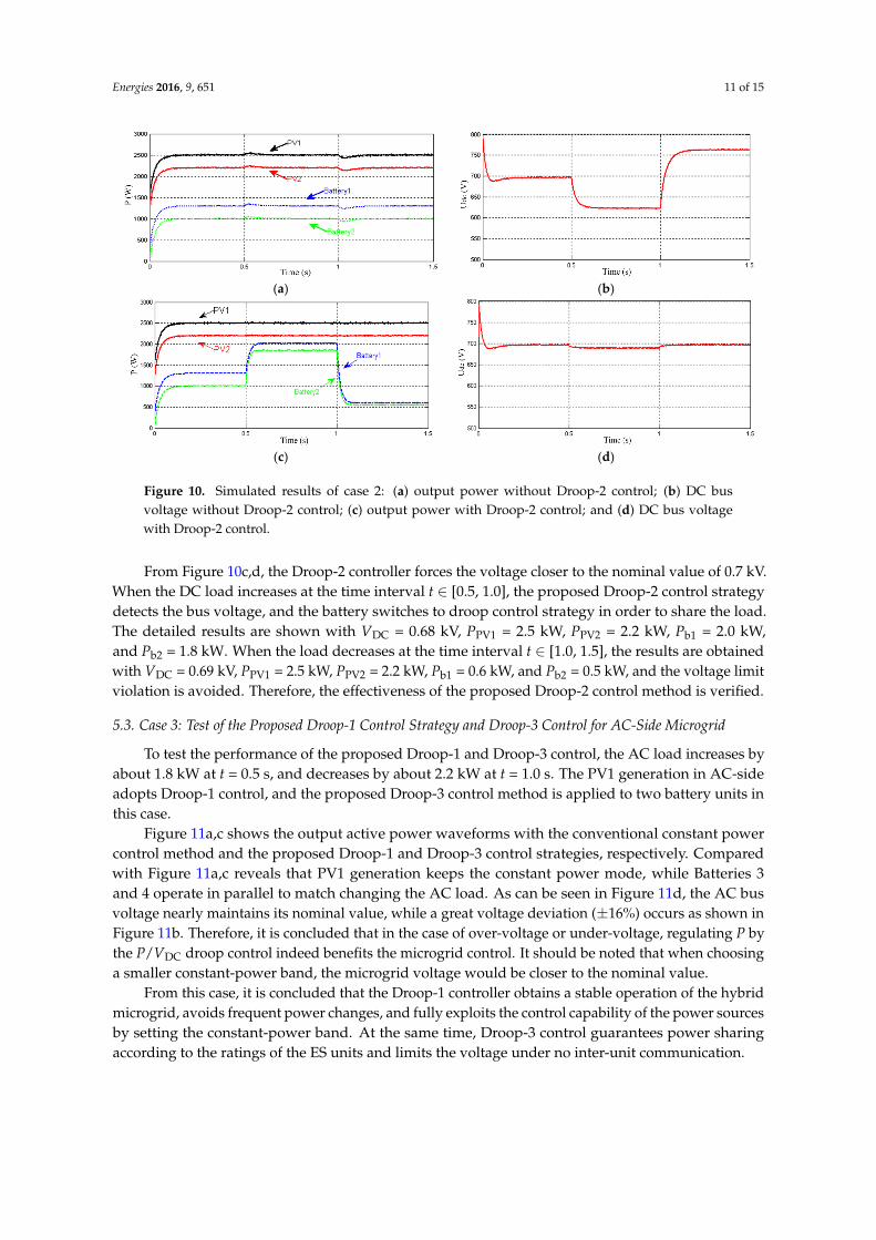
Figure 10. Simulated results of case 2: (a) output power without Droop-2 control; (b) DC busvoltage without Droop-2 control; (c) output power with Droop-2 control; and (d) DC bus voltagewith Droop-2 control.
From Figure 10c,d, the Droop-2 controller forces the voltage closer to the nominal value of 0.7 kV.When the DC load increases at the time interval t ∈ [0.5, 1.0], the proposed Droop-2 control strategydetects the bus voltage, and the battery switches to droop control strategy in order to share the load.The detailed results are shown with VDC = 0.68 kV, PPV1 = 2.5 kW, PPV2 = 2.2 kW, Pb1 = 2.0 kW,and Pb2 = 1.8 kW. When the load decreases at the time interval t ∈ [1.0, 1.5], the results are obtainedwith VDC = 0.69 kV, PPV1 = 2.5 kW, PPV2 = 2.2 kW, Pb1 = 0.6 kW, and Pb2 = 0.5 kW, and the voltage limitviolation is avoided. Therefore, the effectiveness of the proposed Droop-2 control method is verified.
5.3. Case 3: Test of the Proposed Droop-1 Control Strategy and Droop-3 Control for AC-Side Microgrid
To test the performance of the proposed Droop-1 and Droop-3 control, the AC load increases byabout 1.8 kW at t = 0.5 s, and decreases by about 2.2 kW at t = 1.0 s. The PV1 generation in AC-sideadopts Droop-1 control, and the proposed Droop-3 control method is applied to two battery units inthis case.
Figure 11a,c shows the output active power waveforms with the conventional constant powercontrol method and the proposed Droop-1 and Droop-3 control strategies, respectively. Comparedwith Figure 11a,c reveals that PV1 generation keeps the constant power mode, while Batteries 3and 4 operate in parallel to match changing the AC load. As can be seen in Figure 11d, the AC busvoltage nearly maintains its nominal value, while a great voltage deviation (±16%) occurs as shown inFigure 11b. Therefore, it is concluded that in the case of over-voltage or under-voltage, regulating P bythe P/VDC droop control indeed benefits the microgrid control. It should be noted that when choosinga smaller constant-power band, the microgrid voltage would be closer to the nominal value.
From this case, it is concluded that the Droop-1 controller obtains a stable operation of the hybridmicrogrid, avoids frequent power changes, and fully exploits the control capability of the power sourcesby setting the constant-power band. At the same time, Droop-3 control guarantees power sharingaccording to the ratings of the ES units and limits the voltage under no inter-unit communication.

Energies 2016, 9, 651 12 of 15Energies 2016, 9, 651 12 of 15
(a) (b)
(c) (d)
Figure 11. Simulated results of case 3: (a) output active power without Droop‐1 and Droop‐3 control;
(b) AC bus phase voltage without Droop‐1 and Droop‐3 control; (c) output active power with
proposed Droop‐1 and Droop‐3 control; and (d) AC bus phase voltage with proposed Droop‐1 and
Droop‐3 control.
5.4. Case 4: Test of the Proposed Control Strategy for Interlinking Converter and Overall Hybrid Microgrid
To verify the overall system responses, the proposed control strategy of the IC is applied. The
AC load increases by about 3.5 kW at t = 0.5 s, leading to an excess of the AC‐side capacity.
Furthermore, the active power on AC‐side decreases about 4.5 kW, and reactive power increases by
about 1.0 kVar at time t = 1.0 s. Notice that the DC load has remained constant.
Figure 12a,b shows the load current and the AC/DC bus voltage waveforms with the proposed
control method. It can be seen that the bus voltages are close to the rated value. Then, the strong
voltage regulation ability is obtained. The active power and reactive power of all units in hybrid
system are shown in Figure 12c,d. At the first stage t [0, 0.5], all units operated with PPV1 = 2.5 kW,
PPV2 = 2.2 kW, Pb1 = 1.3 kW, and Pb2 = 1.0 kW on the DC‐side. The active power control mechanism of
the IC is disabled, and thus operating losses are avoided. When the AC load changes at t = 0.5 s,
exceeding the AC bus capacity, and the DC‐side has power remaining, the IC is activated with the
power transmission Pic = 2.0 kW, Qic = 0 kVar, PPV1 = 2.5 kW, PPV2 = 2.2 kW, Pb1 = 2.3 kW, and Pb2 = 2.0
kW on the DC‐side. However, the AC‐side PV1 controlled with the MPPT mode keeps constant
output power, and the Batteries 3 and 4 with Droop‐3 controller have reached the capacity limit. The
detailed results are shown with PPV1 = 2.5 kW, Pb3 = 2.5 kW, Pb4 = 2.0 kW on the AC‐side, as seen in
Figure 12c,d. After t = 1.0 s, the active power is reduced to the capacity range of the AC‐side so that
the AC/DC sides can meet the load demand and the active power control of the IC is not enabled. As
can be seen in Figure 12e, the transmitted power Pic is 0. However, as the AC microgrid cannot satisfy
the reactive power demand, the reactive power control for the ICs is operated as STATCOM. So the
transmitted reactive power Qic from DC‐side is 1.0 kVar.
It is concluded that the IC is a key element of the AC/DC hybrid for energy transmission, which
not only can realize the transfer of active power and maintain the power balance of a hybrid
microgrid system, but also provide reactive power compensation and other functions.
Figure 11. Simulated results of case 3: (a) output active power without Droop-1 and Droop-3control; (b) AC bus phase voltage without Droop-1 and Droop-3 control; (c) output active powerwith proposed Droop-1 and Droop-3 control; and (d) AC bus phase voltage with proposed Droop-1and Droop-3 control.
5.4. Case 4: Test of the Proposed Control Strategy for Interlinking Converter and Overall Hybrid Microgrid
To verify the overall system responses, the proposed control strategy of the IC is applied. The ACload increases by about 3.5 kW at t = 0.5 s, leading to an excess of the AC-side capacity. Furthermore,the active power on AC-side decreases about 4.5 kW, and reactive power increases by about 1.0 kVar attime t = 1.0 s. Notice that the DC load has remained constant.
Figure 12a,b shows the load current and the AC/DC bus voltage waveforms with the proposedcontrol method. It can be seen that the bus voltages are close to the rated value. Then, the strongvoltage regulation ability is obtained. The active power and reactive power of all units in hybridsystem are shown in Figure 12c,d. At the first stage t ∈ [0, 0.5], all units operated with PPV1 = 2.5 kW,PPV2 = 2.2 kW, Pb1 = 1.3 kW, and Pb2 = 1.0 kW on the DC-side. The active power control mechanismof the IC is disabled, and thus operating losses are avoided. When the AC load changes at t = 0.5 s,exceeding the AC bus capacity, and the DC-side has power remaining, the IC is activated withthe power transmission Pic = 2.0 kW, Qic = 0 kVar, PPV1 = 2.5 kW, PPV2 = 2.2 kW, Pb1 = 2.3 kW,and Pb2 = 2.0 kW on the DC-side. However, the AC-side PV1 controlled with the MPPT mode keepsconstant output power, and the Batteries 3 and 4 with Droop-3 controller have reached the capacitylimit. The detailed results are shown with PPV1 = 2.5 kW, Pb3 = 2.5 kW, Pb4 = 2.0 kW on the AC-side,as seen in Figure 12c,d. After t = 1.0 s, the active power is reduced to the capacity range of theAC-side so that the AC/DC sides can meet the load demand and the active power control of the ICis not enabled. As can be seen in Figure 12e, the transmitted power Pic is 0. However, as the ACmicrogrid cannot satisfy the reactive power demand, the reactive power control for the ICs is operatedas STATCOM. So the transmitted reactive power Qic from DC-side is 1.0 kVar.
It is concluded that the IC is a key element of the AC/DC hybrid for energy transmission,which not only can realize the transfer of active power and maintain the power balance of a hybridmicrogrid system, but also provide reactive power compensation and other functions.

Energies 2016, 9, 651 13 of 15Energies 2016, 9, 651 13 of 15
(a) (b)
(c) (d)
(e)
Figure 12. Simulated results of case 4: (a) the AC load varying current waveform; (b) DC and AC bus
voltage; (c) output active power of units on the DC‐side; and (d) output active power of units on the
AC‐side; (e) output active power and reactive power of IC.
6. Conclusions
This paper proposes an autonomous power flow control to coordinate distributed components
of a hybrid microgrid, consisting of ES units, PV generators, and interlink converters. The modified
Droop‐1 control is presented for PV generators, which considers the specific characteristics of
generation units and avoids output power changes. No communication for the primary control is
required, and the allowable voltage deviation from its nominal value is effectively used.
Furthermore, to avoid voltage limit violation, a novel Droop‐2 control strategy is implemented
to DC‐side storage. Results show that proper power sharing and supply‐demand balancing in
islanded microgrids are achieved without communication. Moreover, the combination (Droop‐3) of
two control principles is introduced in order to obtain the advantages of both.
As a key element of a hybrid microgrid, an efficient control scheme of the IC is proposed with
progressive energy flow tuning. Results show that the developed control can operate autonomously
without fast communication links. It allows energy flow across the hybrid microgrid only when one
of two sides is over‐loaded, avoiding the operating losses. Furthermore, the IC can operate as a
STATCOM to satisfy the reactive power demand. Finally, simulations results are provided to verify
the effectiveness and performance of the proposed control strategy.
Acknowledgments: This work was supported by the National Natural Science Foundation of China under Grant
No. 61573384 and the National High‐tech R & D Program of China (863 Program) under Grant No. 2015AA050604.
Author Contributions: The paper was a collaborative effort between the authors. The authors contributed
collectively to the theoretical analysis, modeling, simulation, and manuscript preparation.
Conflicts of Interest: The authors declare no conflict of interest.
Figure 12. Simulated results of case 4: (a) the AC load varying current waveform; (b) DC and AC busvoltage; (c) output active power of units on the DC-side; and (d) output active power of units on theAC-side; (e) output active power and reactive power of IC.
6. Conclusions
This paper proposes an autonomous power flow control to coordinate distributed componentsof a hybrid microgrid, consisting of ES units, PV generators, and interlink converters. The modifiedDroop-1 control is presented for PV generators, which considers the specific characteristics ofgeneration units and avoids output power changes. No communication for the primary controlis required, and the allowable voltage deviation from its nominal value is effectively used.
Furthermore, to avoid voltage limit violation, a novel Droop-2 control strategy is implemented toDC-side storage. Results show that proper power sharing and supply-demand balancing in islandedmicrogrids are achieved without communication. Moreover, the combination (Droop-3) of two controlprinciples is introduced in order to obtain the advantages of both.
As a key element of a hybrid microgrid, an efficient control scheme of the IC is proposed withprogressive energy flow tuning. Results show that the developed control can operate autonomouslywithout fast communication links. It allows energy flow across the hybrid microgrid only whenone of two sides is over-loaded, avoiding the operating losses. Furthermore, the IC can operate asa STATCOM to satisfy the reactive power demand. Finally, simulations results are provided to verifythe effectiveness and performance of the proposed control strategy.
Acknowledgments: This work was supported by the National Natural Science Foundation of China under GrantNo. 61573384 and the National High-tech R & D Program of China (863 Program) under Grant No. 2015AA050604.

Energies 2016, 9, 651 14 of 15
Author Contributions: The paper was a collaborative effort between the authors. The authors contributedcollectively to the theoretical analysis, modeling, simulation, and manuscript preparation.
Conflicts of Interest: The authors declare no conflict of interest.
References
1. Yan, B.; Wang, B.; Zhu, L. A novel, stable, and economic power sharing scheme for an autonomous microgridin the energy internet. Energies 2015, 8, 12741–12764. [CrossRef]
2. Lim, Y.; Kim, H.M.; Kinoshita, T. Distributed load-shedding system for agent-based autonomous microgridoperations. Energies 2014, 7, 385–401. [CrossRef]
3. Molderink, A.; Bakker, V.; Bosman, M.; Hurink, L.; Smit, G.J.M. Management and control of domestic smartgrid technology. IEEE Trans. Smart Grid 2010, 1, 109–119. [CrossRef]
4. Moslehi, K.; Kumar, R. A reliability perspective of the smart grid. IEEE Trans. Smart Grid 2010, 1, 57–64.[CrossRef]
5. Gu, W.; Liu, W.; Wu, Z.; Zhao, B.; Chen, W. Cooperative control to enhance the frequency stability of islandedmicrogrids with DFIG-SMES. Energies 2013, 6, 3951–3971. [CrossRef]
6. Xu, Z.; Yang, P.; Zeng, Z.; Peng, J.; Zhao, Z. Black start strategy for PV-ESS multi-microgrids withthree-phase/single-phase architecture. Energies 2016, 9, 372. [CrossRef]
7. Patterson, M.; Macia, N.F.; Kannan, A.M. Hybrid microgrid model based on solar photovoltaic battery fuelcell system for intermittent load applications. IEEE Trans. Energy Convers. 2015, 30, 359–366. [CrossRef]
8. Alobeidli, K.A.; Syed, M.H.; El-Moursi, M.S. Novel coordinated voltage control for hybrid micro-grid withislanding capability. IEEE Trans. Smart Grid 2015, 6, 1116–1127. [CrossRef]
9. Rocabert, J.; Luna, A.; Blaabjerg, F.; Rodriguez, P. Control of power converters in AC microgrids. IEEE Trans.Power Electron. 2012, 27, 4734–4749. [CrossRef]
10. Hajizadeh, A.; Golkar, M.A. Intelligent power management strategy of hybrid distributed generation system.Int. J. Electr. Power Energy Syst. 2007, 29, 783–795. [CrossRef]
11. Xiao, H.; Luo, A.; Shuai, Z. An improved control method for multiple bidirectional power converters inhybrid AC/DC microgrid. IEEE Trans. Smart Grid 2016, 7, 340–347. [CrossRef]
12. Baran, M.E.; Mahajan, N.R. DC distribution for industrial systems: Opportunities and challenges. IEEE Trans.Ind. Appl. 2003, 39, 1596–1601. [CrossRef]
13. Salomonsson, D.; Sannino, A. Low-voltage DC distribution system for commercial power systems withsensitive electronic loads. IEEE Trans. Power Deliv. 2007, 22, 1620–1627. [CrossRef]
14. Dursun, E.; Kilic, O. Comparative evaluation of different power management strategies of a stand-alonePV/Wind/PEMFC hybrid power system. Int. J. Electr. Power Energy Syst. 2012, 34, 81–89. [CrossRef]
15. Loh, P.C.; Ding, L.; Yi, K.C.; Blaabjerg, F. Autonomous operation of hybrid microgrid with AC and DCsubgrids. IEEE Trans. Power Electron. 2013, 28, 2214–2223. [CrossRef]
16. Xu, L.; Chen, D. Control and operation of a DC microgrid with variable generation and energy storage.IEEE Trans. Power Deliv. 2011, 26, 2513–2522. [CrossRef]
17. Lai, C.M.; Yang, M.J. A high-gain three-port power converter with fuel cell, battery sources and stackedoutput for hybrid electric vehicles and DC microgrids. Energies 2016, 9, 180. [CrossRef]
18. Farzam, N.; Li, Y.W. Overview of power management strategies of hybrid AC/DC microgrid. IEEE Trans.Power Electron. 2015, 30, 7072–7089.
19. Mohammadia, M.; Nafar, M. Fuzzy sliding-mode based control (FSMC) approach of hybrid micro-grid inpower distribution systems. Int. J. Electr. Power Energy Syst. 2013, 51, 232–242. [CrossRef]
20. Poh, C.L.; Ding, L.; Yi, K.C.; Frede, B. Hybrid AC-DC microgrids with energy storages and progressiveenergy flow tuning. IEEE Trans. Power Electron. 2013, 28, 1533–1543.
21. Tan, X.; Li, Q.; Wang, H. Advances and trends of energy storage technology in Microgrid. Int. J. Electr. PowerEnergy Syst. 2013, 44, 179–191. [CrossRef]
22. Hajizadeh, A.; Golkar, M.A. Control of hybrid fuel cell/energy storage distributed generation system againstvoltage sag. Int. J. Electr. Power Energy Syst. 2010, 32, 488–497. [CrossRef]
23. Noroozian, R.; Abedi, M.; Gharehpetianb, G.B.; Hosseini, S.H. Distributed resources and DC distributionsystem combination for high power quality. Int. J. Electr. Power Energy Syst. 2010, 32, 769–781. [CrossRef]

Energies 2016, 9, 651 15 of 15
24. Holtz, J.; Lotzkat, W.; Werner, K.H. A high power multitransistor inverter uninterruptible power supplysystem. IEEE Trans Power Electron. 1998, 3, 278–285. [CrossRef]
25. Radwan, A.A.A.; Mohamed, Y.A.R.I. Networked control and power management of AC/DC hybridmicrogrids. IEEE Syst. J. 2014, PP, 1–12. [CrossRef]
26. Lu, X.; Guerrero, J.M.; Sun, K.; Juan, C.V.; Remus, T.; Huang, L. Hierarchical control of parallel AC-DCconverter interfaces for hybrid microgrids. IEEE Trans. Smart Grid 2014, 5, 683–692. [CrossRef]
27. Poh, C.L.; Li, D.; Chai, Y.K.; Blaabjerg, F. Autonomous control of interlinking converter with energy storagein hybrid AC-DC microgrid. IEEE Trans. Ind. Appl. 2013, 49, 1374–1382.
28. Wang, P.; Jin, C.; Zhu, D.; Tang, Y.; Loh, P.C.; Choo, F.H. Distributed control for autonomous operation ofa three-port AC/DC/DS hybrid microgrid. IEEE Trans. Ind. Electron. 2015, 62, 1279–1290. [CrossRef]
29. Liu, X.; Wang, P.; Loh, P.C. A hybrid AC/DC microgrid and its coordination control. IEEE Trans. Smart Grid2011, 2, 278–286.
30. Vandoorn, T.L.; Meersman, B.; Degroote, L.; Renders, B.; Vandevelde, L. A control strategy for islandedmicrogrids with DC-link voltage control. IEEE Trans. Power Deliv. 2011, 26, 703–713. [CrossRef]
31. Vandoorn, T.L.; Meersman, B.; Jeroen, D.M.; Vandevelde, L. Analogy between conventional grid controland islanded microgrid control based on a global DC-link voltage droop. IEEE Trans. Power Deliv. 2012, 27,1405–1414. [CrossRef]
32. Vandoorn, T.L.; Jeroen, D.M.; Meersman, B.; Josep, M.G.; Vandevelde, L. Voltage-based control of a smarttransformer in a microgrid. IEEE Trans. Ind. Electron. 2013, 60, 1291–1305. [CrossRef]
33. Li, J.; Wei, W.; Xiang, J. A simple sizing algorithm for stand-alone PV/wind/battery hybrid microgrids.Energies 2012, 5, 5307–5323. [CrossRef]
34. Song, N.O.; Lee, J.H.; Kim, H.M.; Im, Y.H.; Lee, J.Y. Optimal energy management of multi-microgrids withsequentially coordinated operations. Energies 2015, 8, 8371–8390. [CrossRef]
35. Moradi, M.H.; Eskandari, M.; Hosseinian, S.M. Cooperative control strategy of energy storage systemsand micro sources for stabilizing microgrids in different operation modes. Int. J. Electr. Power Energy Syst.2016, 78, 390–400. [CrossRef]
36. Mohammadi, F.D.; Feliachi, A. Adaptive price management in hybrid microgrid in presence of PV andbattery energy storage system. In Proceedings of the 2014 IEEE PES T&D Conference and Exposition,Chicago, IL, USA, 14–17 April 2014.
37. Guerrero, J.M.; Matas, J.; De Vicuña, L.G. Decentralized control for parallel operation of distributedgeneration inverters using resistive output impedance. IEEE Trans. Ind. Electron. 2007, 54, 994–1004.[CrossRef]
38. Mastromauro, R.A.; Liserre, M.; Dell’Aquila, A. Control issues in single-stage photovoltaic systems: MPPT,current and voltage control. IEEE Trans. Ind. Inform. 2012, 8, 241–254. [CrossRef]
39. Esram, T.; Chapman, P.L. Comparison of photovoltaic array maximum power point tracking techniques.IEEE Trans. Energy Convers. 2007, 22, 439–449. [CrossRef]
© 2016 by the authors; licensee MDPI, Basel, Switzerland. This article is an open accessarticle distributed under the terms and conditions of the Creative Commons Attribution(CC-BY) license (http://creativecommons.org/licenses/by/4.0/).