a comprehensive static model for corex process
TRANSCRIPT
© 2012 ISIJ 2186
ISIJ International, Vol. 52 (2012), No. 12, pp. 2186–2193
A Comprehensive Static Model for COREX Process
Yingxia QU,1)* Zongshu ZOU1) and Yanping XIAO2)
1) School of Materials & Metallurgy, Northeastern University, Shenyang, 110004 China.2) Department of Materials Science and Engineering, Delft University of Technology, Mekelweg 2, 2628 CD Delft.
(Received on May 31, 2012; accepted on July 31, 2012)
COREX is the first industrially proven smelting reduction process in the world. In this paper, a staticmodel has been developed based on mass and heat balances. Further, a zoned model for the melter-gasifier was established on the basis of the static model. The model is capable of calculating theconsumption of iron ores, coal, fluxes, the volume and composition of the slag and the volume and com-position of the reducing gas from melter-gasifier. The model enables the examination of the changes ofmaterial and heat flows induced by the variations of operation parameters and raw materials chemicalcompositions. The model allows optimization of operation parameters of the COREX process, which canthus be used to improve the plant operation under different conditions.
KEY WORDS: COREX process; reduction shaft; melter-gasifier; smelting reduction; static model; zonedmodel.
1. Introduction
Up to now, iron for producing steel is still mainlyproduced in the conventional ironmaking process of blastfurnaces, which has evolved into highly efficient reactors.Furthermore, blast furnaces use coke which requires specialcoal and the coke become more and more expensive.Besides, coke plants have many environment problemsassociated with their operation. Thus, from an economicaland environmental point of view to produce iron withoutcoke, numbers of smelting reduction process have beendeveloped. COREX is the world’s first and the only com-mercially established smelting-reduction process, as analternative route to blast furnace, based mainly on non-coking coal. It is regarded as one of the most promisingalternative iron-making processes in the world which isdeveloped and marketed by Voest Alpine Industrianlagenbau(VAI), Austria.
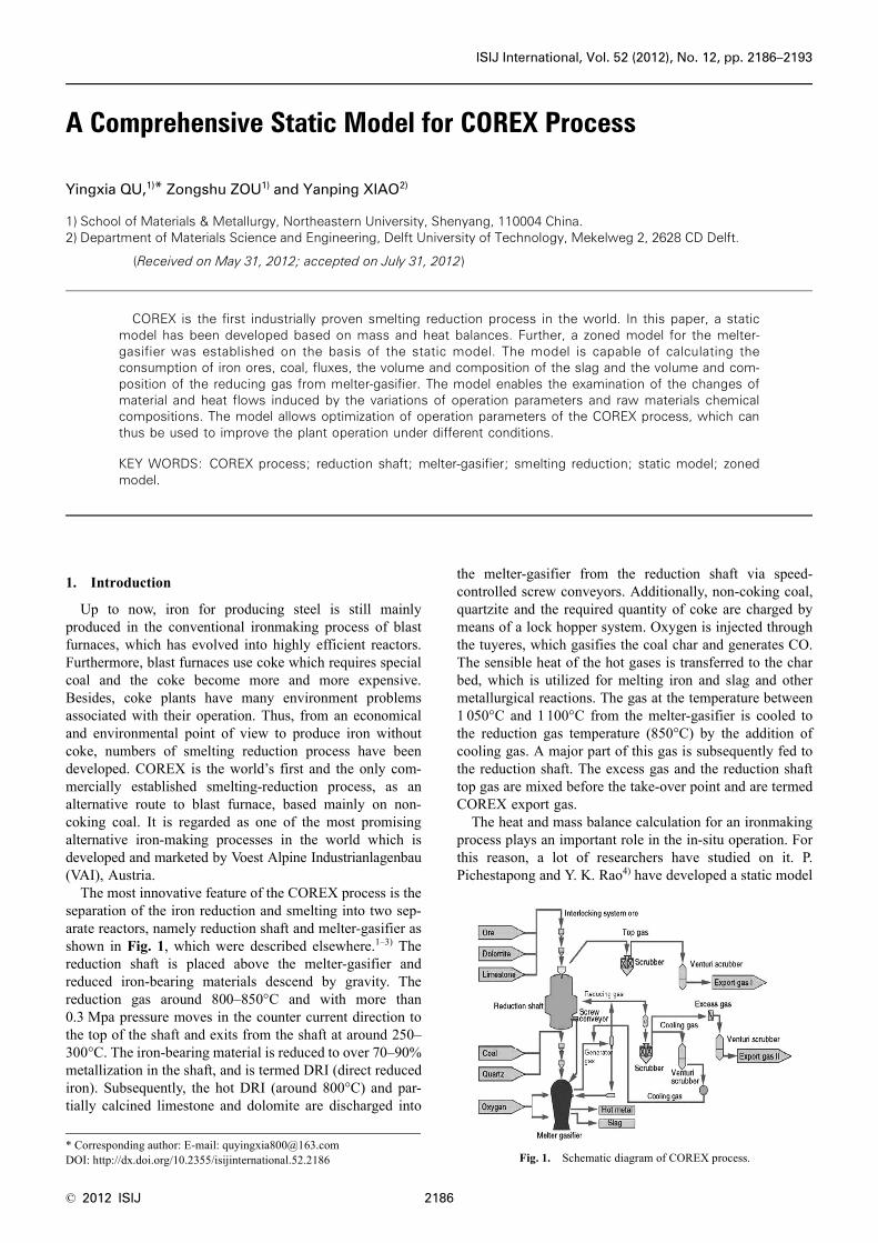
The most innovative feature of the COREX process is theseparation of the iron reduction and smelting into two sep-arate reactors, namely reduction shaft and melter-gasifier asshown in Fig. 1, which were described elsewhere.1–3) Thereduction shaft is placed above the melter-gasifier andreduced iron-bearing materials descend by gravity. Thereduction gas around 800–850°C and with more than0.3 Mpa pressure moves in the counter current direction tothe top of the shaft and exits from the shaft at around 250–300°C. The iron-bearing material is reduced to over 70–90%metallization in the shaft, and is termed DRI (direct reducediron). Subsequently, the hot DRI (around 800°C) and par-tially calcined limestone and dolomite are discharged into
the melter-gasifier from the reduction shaft via speed-controlled screw conveyors. Additionally, non-coking coal,quartzite and the required quantity of coke are charged bymeans of a lock hopper system. Oxygen is injected throughthe tuyeres, which gasifies the coal char and generates CO.The sensible heat of the hot gases is transferred to the charbed, which is utilized for melting iron and slag and othermetallurgical reactions. The gas at the temperature between1 050°C and 1 100°C from the melter-gasifier is cooled tothe reduction gas temperature (850°C) by the addition ofcooling gas. A major part of this gas is subsequently fed tothe reduction shaft. The excess gas and the reduction shafttop gas are mixed before the take-over point and are termedCOREX export gas.
The heat and mass balance calculation for an ironmakingprocess plays an important role in the in-situ operation. Forthis reason, a lot of researchers have studied on it. P.Pichestapong and Y. K. Rao4) have developed a static model
* Corresponding author: E-mail: [email protected]: http://dx.doi.org/10.2355/isijinternational.52.2186 Fig. 1. Schematic diagram of COREX process.

ISIJ International, Vol. 52 (2012), No. 12
2187 © 2012 ISIJ
for COREX process. The operating data used in the modelwas from COREX C-1000 unit at the Pretoria (South Africa)works of the Iscor Ltd. The scale of the model was basedon producing 1 t hot metal. Mass balance was calculatedthrough the element balance equations of Fe, C, H and O.The carbon balance in this paper shows that about 50% ofthe dust was collected in the hot-cyclone and returned to themelter-gasifier via dust burners. In the reduction shaft, 95%of total iron in the ore was converted to metallic iron andthree-fourths of the total reduction was with CO and the restwith H2. However, this assumption is with uncertainties.From the heat balance calculation, it was found that 90% ofthe heat required in the melter-gasifier was generated by theexothermic reactions. In the reduction shaft, 80% of the heatwas taken by the reducing gas. Kumar and Garg5) developeda composite model for computational analysis of theCOREX process. The model also combines a set of commonmaterial and heat balance equations. Raw materials con-sumptions were calculated by mass balance equations forFe, Mn, MgO, Al2O3 and CaO/SiO2. The slag volume andcomposition were calculated from the total amount of Al2O3
coming from raw materials and % Al2O3 required in theslag. And the module determines slag by assuming thatCaO + MgO + SiO2 + Al2O3 = 96.5%. In this way, the qua-ternary basicity in the slag was determined, but it was notused as a direct variable parameter to control the model.They stated that the major variables impacting upon slagrate are fuel rate and variation in raw material compositions,particularly Al2O3, ranging from 2.2 to 2.8%. For a 0.1%increase of Al2O3 in pellets, the slag volume increased by8 kg/tHM (per ton hot metal).
In this study, a raw materials optimization module anduser friendly visual operation interfaces were added to thestatic model. The two parallel raw materials consumptionmodules based on different purposes which are direct con-trol of basicity and direct control of Al2O3 in the slag werecombined into the overall model. The operator can select thesuitable one to get an expected prediction. Further more, azoned static model for melter-gasifier was developed on thebasis of the overall static model, which is helpful to getmore insight of the melter-gasifier.
2. Static Model and Computation Method
The static process model is the core of the computer-control system of the COREX process in the plant. Theconsumption of raw materials, fluxes, the volume and com-position of the slag and the volume and composition of thegenerator gas (the off-gas from the melter-gasifier) andreducing gas (the gas fed into the reduction shaft) as shownin Fig. 1 are calculated by a set of mass and heat balanceequations and constraint conditions which include binarybasicity (CaO/SiO2), quaternary basicity ((CaO+MgO)/(SiO2+Al2O3)) and the composition of the hot metal. Thetypical range of input values and initial value of outputswere taken from the literature3) and plant data. The mainreactions taking place inside the shaft include the reductionof iron oxide by CO/H2, calcination of limestone and dolo-mite, carbon deposition reaction and formation of Fe3C. Inthe melter-gasifier, in addition to the reduction of residualiron oxide as well as the decomposition of residual
limestone and dolomite, the reactions also include the devol-atilisation of coal, decomposition of volatile matter andliberation of methane and higher hydrocarbons, carbon solu-tion and char combustion reactions, steam-carbon reactionand water gas shift reaction. Finally, melting and formationof hot metal and slag take place in the hearth of the melter-gasifier.
2.1. Construction of the Comprehensive Static ModelThe overall static model is consisted of six sub modules
which are raw material optimization module, raw materialand flux consumption module, generator gas volume andcomposition module, coal and oxygen consumption module,shaft furnace balance module and the last one is user inter-face module. It is assumed that hematite decomposes towustite and oxygen, and then oxygen reacts with reducinggas or carbon. The same procedure applies for the reductionof wusite. Because the model was set up at the steady state,the simplification won’t change the final results. The con-cept of the complicated static model is illustrated as a flowchart in Fig. 2. The model started with the heat and massbalance calculation of melter-gasifier, and then the results ofthe model of melter-gasifier were used as the initial input forthe computation of the model of shaft furnace. All theresults of the mathematical model were saved in the database.
The raw material optimization module works as a tool fordata pretreatment, by which the operating parameters can beadjusted. The main function of the raw material optimiza-tion module is to calculate the ratios of coal/coke and ironore/pellet. The target compositions of coal mixture and oremixture are the empirical values from the COREX plants,which were mostly used to meet the requirement of COREXprocess. The material optimization module was developedwith the method of least-squares algorithm. It can exportseveral groups of mixed material compositions which arethe closest to target value. At the same time, the price issue
Fig. 2. Flow chart of the static model.

© 2012 ISIJ 2188
ISIJ International, Vol. 52 (2012), No. 12
is taken into account as the second important factor. Theoperators can make a choice considering the balancebetween the composition and price. The coal consumptionis determined by several factors like the chemical composi-tion of coal, gas oxidation degree and heat loss etc. Thismodule assumes that the heat loss of the melter-gasifier isconstant. Coal consumption is calculated through iterationuntil the total heat input equals the total heat output. Theconsumption of oxygen is calculated from oxygen balanceof the melter-gasifier. The composition of reducing gas isthe same as the generator gas and the temperature isassumed to be 850°C when it is injected into the reductionshaft furnace. It is assumed that the metallization of ironbearing materials in the reduction shaft is 80% according tothe experience of plant, and calcination degrees of limestoneand dolomite are 50% and 100% respectively before leavingthe shaft at 800°C. To keep the reduction ability of reducinggas, the reduction potential of reducing gas at the top ofshaft furnace should be higher than 1.26 ((CO + H2)/(CO2 +H2O)) and its minimum temperature was set to be 300°C.
The user interface module aims to get user-friendly oper-ation interfaces for the operator. The boundary conditionsand the compositions of raw materials are saved in the data-base and displayed on the interface by applying the ADO(ActiveX Data Objects) technology. All the initial condi-tions can be reset on the interface directly without accessingthe database. The results of the model are also displayed onthe interface and saved in the database with a name givenby the user.
2.1.1. Raw Material Consumption ModuleThe core of the calculation of the overall static model is
the raw material consumption module which aims to calcu-late the consumption of raw materials (pellets, ores, fluxes,etc.), as well as the amount and chemical composition of theslag. Basicities are the important parameter of measuring theviscosity of the slag. For that the binary basicity R2 (CaO/SiO2) and quaternary basicity R4 ((CaO+MgO)/(SiO2+Al2O3))of the slag were initialized before calculation and can bechanged easily on the user interface as described above. Themodule solves four balance equations (Eqs. (1)–(4)) for Fe,binary basicity, quaternary basicity and slag amount. Theinput items for the module are: (a) composition of raw mate-rials, (b) specified consumption of quartz, (c) expected R2
and R4 values in the slag. Ore consumption can be calculat-ed from the equation of Fe balance, and the amount of thelimestone and the dolomite and the composition of slag areobtained from equations of (2) and (3). In this way, theamount of quartz and the other gangue materials determinethe amount of the slag.
Four balance equations are listed as follows.
• Fe balance
.......................................... (1)
• Binary basicity
............................ (2)
• Quaternary basicity
........... (3)
• Quantity of slag
.......................................... (4)
The other approach for calculating raw materials consump-tions is solved with a set of balance equations of Fe, R2,MgO and Al2O3. Instead of equations of (3) and (4), Eqs. (5)and (6) is applied,
• (MgO) balance
.......................................... (5)
• (Al2O3) balance
.......................................... (6)
Here, in the equations, i denotes the raw materials includingiron ore, coal, limestone, dolomite and quartz; mi representsthe mass of raw material for producing one ton of hot metal(kg); w(j)i denotes the mass fraction of j in i material; mHM
is the mass of hot metal, one ton in this study; mslag denotesthe mass of slag (kg); w(Fe)HM denotes the mass fraction ofFe in hot metal; w(FeO)slag, w(MgO)slag, w(Al2O3)slag denotesthe mass fraction of FeO, MgO and Al2O3 in slag, respec-tively; w(j)dust denotes the mass fraction of j in the flue dust.Mj denote the mass of j in slag.
2.1.2. Generator Gas Volume and Composition ModuleIn this module, the volume fraction of CH4 is assumed to
be constant and all the N2 comes from the volatile of coaland the carrier gas. The volume and composition of gener-ator gas is calculated by solving the four balance equationsof H, C, equilibrium constant of water gas shift reaction andgas oxidation degree which are given below:
• Hydrogen balance
... (7)
• Carbon balance
.......................................... (8)
• The equilibrium constant of water gas shift reaction
.... (9)
• Gas oxidation degree
... (10)
In the above four equations, , , , , denotethe volume of H2O, CO2, CO, H2, CH4 in gas for producing
m w m w m wi ii
HM HM slag slagFe Fe FeO× ( ) = × [ ] + × ( ) ×∑ 56 72
R m m2 = CaO SiO2
R m m m m4 = +( ) +( )CaO MgO SiO Al O2 2 3
m m m m m m m m
w
slag CaO SiO Al O MgO MnO CaS P O
slag
2 2 3 2 5
FeO)
= + + + + + +
−
( )
(1(( )
m w m w m wi ii
dust dust slag slagMgO) MgO] MgO)× = × + ×∑ ( [ (
m w m w m wi 2 3 ii
dust 2 3 dust slag 2 3 slagAl O ) Al O ] Al O )× = × + ×∑ ( [ (
m w V V Vi ii
CH H H OH4 2 2
× ( ) = × + × +⎡⎣ ⎤⎦∑ 4 2 22 4( ) .
m w m w V V Vi ii
HM HM CO CO CHC C2 4
× ( ) = × [ ] + + +( )×∑ 12 22 4.
K V V V V
T T
= ⋅( ) ⋅( )= − ×( ) ×( )⎡
⎣⎤
H CO CO H O
gas gas
2 2 2
exp . .29 490 26 8 8 314 ⎦⎦
OD V V V V V V= +( ) + + +( )H O CO H O CO H CO2 2 2 2 2
VH O2VCO2
VCOVH2
VCH4

ISIJ International, Vol. 52 (2012), No. 12
2189 © 2012 ISIJ
1 t hot metal (Nm3). w(C)HM denotes the mass fraction of Cin hot metal; w(H)i and w(C)i are the mass fraction of H andC in i material; Tgas and OD are the gas temperature (K) andoxidation degree.
2.2. Model Establishment for the Reaction Zones ofMelter-gasifier
The overall static model of COREX process can only pro-vide the information of mass flows and heat flows at theinlet and outlet of the two reactors. The melter-gasifier is acomplicated reactor in which multiphase reactions takeplace continuously. In order to get more insights into thereactor, a five-zoned static model was developed for themelter-gasifier, which is useful for studying the energy dis-tribution, chemical reactions and the temperature and com-position of the generator gas in each zone. According to thephysical state of the burden and the different conditions ofchemical reactions, the melter-gasifier can be divided intofive zones from top to bottom, which are the free board, flu-idized bed, packed bed, raceway and hearth as shown in Fig.3. However, whether there is a fluidized bed above thepacked bed is still a question to all the researchers. The siteoperators in BaoSteel claim that there would be a thin layerof fluidized bed of about 100 mm. Kumar P. P and co-workers6) combined the fluidized bed and the packed bed intheir work. In this study, the fluidized bed was studied asone of the five zones.
On the basis of the overall COREX process model, theresults of composition and temperature of the generator gascan be obtained as the boundary condition of the free board,and the results of the compositions and temperatures of theslag and hot metal are used as the boundary condition of thehearth. Therefore, the calculation of the zoned static modelstarts from both sides of the furnace which are the free boardand hearth zone, and finally meets at the packed bed. Thefollowing assumptions are made in the model: (a) all thedust is generated in the free board zone, and the carbon inthe dust is from coal, (b) all the injected oxygen in the race-way reacts with carbon generating the reducing gas of CO,(c) the temperature of injected oxygen and pulverized coal
is at room temperature, (d) all the residual dolomite andlimestone from the shaft furnace complete their decomposi-tion in the packed bed.
In the zoned static model, three critical parameters areconsidered, which are the distribution ratio of oxygen, theadiabatic flame temperature at raceway and the calculationof the heating value of coal. In this study, certain amount ofpulverized coal is injected into the raceway through oxygentuyeres as the substitution of part of lump coal chargingfrom the dome of the melter-gasifer. Such an operation willaffect directly the adiabatic flame temperature. Therefore,the three parameters become much more significant for con-sidering pulverized coal injection.
2.2.1. Distribution Ratio of OxygenThe distribution ratio of oxygen is defined as the ratio of
the oxygen input in the free board to the total oxygen inputin the melter-gasifier, which plays an important role indetermining energy distribution and temperature profiles inthe melter-gasifier. It should be adjusted to an appropriatevalue to ensure that the temperature of off-gas of the reactoris between 1 000°C and 1 100°C. If the gas temperature atthe dome of the melter-gasifier is below 950°C, the qualityof the gas goes down due to the incomplete thermal crackingof volatile from coal. Simultaneously, a lot of tar forms inthe pipes of off gas system, and then the pipes are cloggingup due to the accumulation of tar. However, if the gas tem-perature is above 1 100°C, such a high temperature wouldlead to softening and melting of dust in the gas and the dustwould be accumulated at the inlet of the cyclone separator.The off-gas system would also be clogged. On the otherhand, the off-gas takes a lot of heat away from the melter-gasifer, leading to a high energy loss of the furnace. In theraceway, the gas temperature determines the heat transferefficiency from the hot gas to the hearth zone, as the hot gasis the only heat source of the hearth zone. If it’s not strongenough, the separation of slag and metal, as well as the des-ulphurization of hot metal will not reach the expected level,leading to a poor quality of hot metal. Therefore, it is nec-essary to optimize oxygen distribution ratio to control thegas temperatures at the free board and the raceway zone. Inthis model, the oxygen distribution ratio is adjusted by thetemperature difference of charges and gas at the lower sur-face of the free board through interaction.
2.2.2. The Heating Value of CoalOnce the pulverized coal is injected into the raceway and
exposed in the oxidation gas, the coal particles are heatedup quickly, and the reactions of thermal decomposition andcombustion take place intensively. The heat in the racewayconsumed for the reaction of coal volatile thermal decom-position increases with the increase of volatile content in thepulverized coal. In other words, the decomposition of coalvolatile plays an important role in determining the adiabaticflame temperature in the raceway.
The heating value of a fuel includes the lower heating val-ue (Qlow, kJ/kg) and the higher heating value (Qhigh, kJ/kg).The higher heating value of a coal takes into account thelatent heat of vaporization of water in the combustion, whilethe lower heating value of a coal doesn’t. The final productsare CO2, N2 and H2O (g) or H2O (l). A lot of researchers6–8)Fig. 3. Five modeling zones of COREX melter-gasfier.

© 2012 ISIJ 2190
ISIJ International, Vol. 52 (2012), No. 12
have studied the correlation of heating value with composi-tion since the Dulong formula for heating value was pro-posed in 1891. Some formulas of calculating the heatingvalues based on the ultimate analysis while others are basedon the proximate analysis. However, the results are quitedifferent from each other for that they used different typesof coal like lignite, anthracite and soft coal etc. Besides thisreason, the coals used in their experiment were from differ-ent origins, the formulas have many limitations in the appli-cation. In this study, the formula from literature9) is adopted,which combines the ultimate analysis and proximate analy-sis methods, leading to a high-accuracy empirical formula asfollows.
... (11)
The lower heating value is calculated by Eq. (12).
........................ (12)
Where, C, H, S and O denote the mass percentage (%) ofeach element in the coal based on ultimate analysis. Thecapital letters of A and V denote the mass percentage (%)of ash and volatile in the coal.
2.2.3. Raceway Adiabatic Flame TemperatureNormally, the adiabatic flame temperature is the temper-
ature that results from a complete coal combustion processthat occurs without any heat transfer or changes in kineticor potential energy, which describes the temperature thecombustion products theoretically reach if no energy is lostto the outside environment. It is a critical parameter forjudging the situation of the hearth of the traditional processblast furnace, especially the furnace with pulverized coalinjection technology. An appropriate raceway adiabaticflame temperature (RAFT) can guarantee a smooth running,sufficient heat in the furnace as well as high-efficiency pul-verized coal combustion. The relationship between racewayand hearth of COREX is similar to that of blast furnace.Therefore it is also regarded as a significant parameter ofCOREX process. In this model, the RAFT is calculated bythe method of interaction in the raceway zone. For the injec-tion of pulverized coal, the combustion heat transfers tocombustion products, and also supplies heat to the thermaldecomposition of pulverized coal. The RAFT with the injec-tion of pulverized coal is lower than that without pulverizedcoal injection. From this aspect, the effect of the quantity ofpulverized coal injection on RAFT can be predicted.
3. Results and Discussion
Figure 4 shows an example of mass flow sheet ofCOREX process under a typical operation condition. Thecalculation conditions are defined that the metallizationdegree of iron ore in the shaft furnace is 85%, the gas oxi-dation degree at the top of the melter-gasifier is 7% and thetemperature of generator gas is 1 050°C. Under steady state,the consumption of iron ore, flux (limestone, dolomite andquartzite) and coal as well as the consumption of reducinggas by shaft furnace were calculated with the static processmodel. Under this condition, 1 297.87 kg iron ore and953.2 kg coal are required for producing 1 t hot metal.
3.1. Effect of DRI MetallizationThe effect of DRI metallization on coal and oxygen con-
sumptions can be studied with the static model. Higher met-allization degree of DRI requires greater volume of reducinggas or higher reduction potential of the gas in reductionshaft. In the melter-gasifier, the reaction between coal andoxygen, which generates a considerable amount of heat, isthe main heat source and also produces reducing gas for theshaft. The higher the metallization degree of DRI in thereduction shaft, the less quantity of reductant and fuel isneeded in the melter-gasifier. In other words, the consump-tions of coal and oxygen in the melter-gasifier go down withthe increase of metallization degree of DRI as shown in Fig.5. In this group of calculations, the temperature of the gen-erator gas was set to be 1 050°C and gas oxidation degreewas set to be 7%.
The volume of generator gas decreases with the increaseof metallization degree of DRI as shown in Fig. 6. The vol-ume of reducing gas for shaft furnace decreases slowly atthe degree of metallization lower than 80% and thenincreases. The volume of generator gas decreases with theincrease of DRI metallization degree. In the model, the heatbalance of the reactor or constraint of reduction potential ofreducing gas at the top of furnace determines the volume ofreducing gas required by shaft furnace. Heat balance is dom-inant at the given conditions of DRI metallization degreelower than 80%. The iron ore reduced by H2–CO mixture(VH2:VCO=1:3) is slightly exothermic, therefore the volumeof reducing gas for shaft furnace decreases and the con-straint of reduction potential of reducing gas is higher than1.26 in such a case. When the metallization degree is greaterthan 80%, the volume of reducing gas is determined by theconstraint of reduction potential of reducing gas. In order tokeep an appropriate reduction potential of top gas, thereducing gas volume should increase with the increase ofDRI metallization degree. In other words, if the metalliza-tion degree of DRI is around 80%, the reduction potentialof reducing gas just reaches its limit value of 1.26 when theheat balance is satisfied.
From the aspect of making full use of energy and savingraw materials, it seems that it is the optimum status whenthe volume of generator gas from melter-gasifer equals thevolume of reducing gas required by the reduction shaft. But
Q C H S O
A V
high = + + −
+ − −
0 4323 1 595 0 21 0 00152
0 087 0 0152 9 975
. . . .
. . .
Q Q Qhigh low vap= +
Fig. 4. Specific mass flow under a typical operation condition.

ISIJ International, Vol. 52 (2012), No. 12
2191 © 2012 ISIJ
this is not the actual situation. The temperature of the gen-erator gas is 1 050°C. However, the reducing gas for theshaft should be around 850°C for getting a smooth runningof reduction shaft. It means a part of cooling gas should beadded to the generator gas to decrease the gas temperature.The ideal optimum volume of generator gas should equalthe sum of the volume of cooling gas and reducing gas.Therefore, it’s necessary to study the relationship betweenmetallization degree and the excess gas which equals thevolume of generator gas minus the sum of the volume ofcooling gas and reducing gas.
Figure 7 shows the volume of excess gas as a functionof DRI metallization degree when the gas oxidation degreeis varied from 6% to 12%. When the excess gas is abovezero, the volume of generator gas is sufficient for the reduc-ing gas and cooling gas. When the excess gas is below zero,the melter-gasifier and reduction shaft don’t match each oth-er. The area below zero is the inoperable area. When theexcess gas equals zero, it is the theoretical optimum opera-tion. With the increase of gas oxidation degree, the excessgas apparently decreases at the same DRI metallizationdegree. At the same gas oxidation degree, the excess gasdecreases gradually with the increase of DRI metallizationdegree.
On the contrary, it’s also possible to optimize the processat a given DRI metallization degree through adjusting thegas oxidation degree as shown in Fig. 8. When the gas oxi-dation degree becomes higher, the reaction of oxygen withreductant will supply much more heat than low gas oxida-tion degree. On one hand, less coal and oxygen are needed
to generate the required energy, and then the volume of gen-erator gas decreases. On the other hand, if CO and H2 in thegas decrease, more reducing gas should be supplied to thereduction shaft. The optimum gas oxidation degree can thusbe obtained with the model.
3.2. Calculation of Zoned Static ModelZoned static model is a useful tool to get an insight into
each zone. The free board plays an important role in themelter-gasifier. The temperature of burden and gas in thefree board must be within a certain range to keep a smoothrunning. Therefore, it has been drawn more and more atten-tions in-situ. When other conditions are fixed, the tempera-ture of solid materials and gas at the lower surface of freeboard is closely related to the changing of oxygen distribu-tion ratio. In order to study the effect of oxygen distributionratio on the furnace’s behavior, it was set from 0.24 to 0.32in a wider range than the typical range. The results of gasand solid temperature at the lower surface of free board asa function of oxygen distribution ratio were plotted in Fig.9. With the increase of oxygen distribution ratio, the tem-perature of gas which flows into the free board decreasesrapidly and the temperature of solid materials falling intofluidized bed increases. The difference in temperaturebetween gas and solid at the surface becomes smaller. Thatis because the char combustion heat in the raceway decreas-
Fig. 5. Effect of DRI metallization on coal and oxygen consump-tions.
Fig. 6. Effect of DRI metallization on gas volumes.
Fig. 7. Effect of DRI metallization on excess gas at different gasoxidation degrees.
Fig. 8. Effect of gas oxidation degree on gas volumes.

© 2012 ISIJ 2192
ISIJ International, Vol. 52 (2012), No. 12
es for less oxygen injection, while the heat needed by thepacked bed and hearth doesn’t change. Therefore, the gastemperature becomes lower when the gas reaches the freeboard under higher oxygen distribution ratio. After the gasflows into the free board, the reactions of H2, CO, and recy-cled dust with more O2 generate more heat which is mostlyused to heat the gas and solid materials. A small amount ofheat is used for water evaporation and other chemical reac-tions. It leads to the temperature of solid materials becomeshigher at the lower surface of free board. This would accel-erate the chemical reactions in the free board and is thusfavorable for smooth running of the melter-gasifier. Aboveall, the average temperature of solid materials under highoxygen distribution ratio is higher than that under low oxy-gen distribution ratio in the free board.
Figure 10 shows the average temperatures of gas andburden at the upper surface of each zone. In this case, thetemperature of off-gas is assumed to be 1 010°C and the gasoxidation degree is 12%. The burden temperature is alwayslower than the gas temperature all along the height of themelter-gasifier. The temperature of gas generated in theraceway reaches the highest point of 3 200°C. It goes downgreatly to 886°C as the gas flows through the packed bedand fluidized bed. The temperature of gas is increased by theinjection of oxygen. At the lower surface of the free board,when gas temperature is 231°C higher than the burden tem-
perature, the oxygen distribution ratio is 0.29. For the coun-tercurrent flow of gas and burden in the furnace, the gastemperature decreases from the raceway to the free boardand it is around 1 010°C at the top of the melter-gasifier. Asthe burden passes through the fluidized bed, packed bed andraceway, its temperature increases gradually from 380°C,and finally reaches the highest temperature of 1 775°C at thetop of hearth.
3.3. Validation of Adiabatic Flame TemperatureIn order to validate the reliability of the model, the results
of this model were compared with the results from litera-tures and plant data for adiabatic flame temperature. Thetemperatures of the oxygen and pulverized coal are 25°Cand the temperature of char after combustion is assumed tobe 1 600°C. The composition of the coal is shown in Table1. All the calculation results below were obtained based onthe same conditions as mentioned above.
Siemens VAI proposed an empirical formula to calculatethe RAFT (°C) as shown in Eq. (13). Cp,gas is the averagespecific heat capacity of gas mixture (kJ/mol).10)
.... (13)
With this formula, the RATF is calculated to be 4 121.02°C.P. Prachethan Kumar et al.11) from Jindal South West steel
limited (JSW Steel Ltd) studied the RAFT with Eq. (14),where Cp,char (kJ/mol) is the specific heat capacity of charand Cp,CO (kJ/mol) is the specific heat capacity of CO.
........................................ (14)
The RAFT is 3 400°C with this method, which is 721°Clower than the results from VAI.
A patent from Pohang Iron and Steel Co. Ltd (POSCO)12)
reported the experimental data of the RAFT which areshown in Table 2. The experiments were conducted withdifferent quantity of pulverized coal and the temperature atthe raceway was measured by a thermocouple. In order tocompare the experimental results with the results by othermethods under the same conditions, the composition of coallisted in Table 1 is from this patent. From the table, it canbe concluded that the RAFT decreases with the increase ofpulverized coal injection. For example, in case there is noinjection of pulverized coal, the RAFT is 3 878°C and incase the pulverized coal injection is 200 kg/tHM, the RAFTis 3 131°C which is about 700°C lower than that of no injec-tion.
Above all, the RAFT from VAI model is the highest onecompared to the others. The result from JSW Steel Ltd is thelowest one, which is only 3 400°C. Being different from theresults from the two empirical formulas from VAI and JSW,the experimental results revealed by POSCO are much morerealistic. It can be seen apparently that the results of thepresent model are quite close to the results from POSCO. Inthe case of no pulverized coal injection, the result of thismodel is only 1°C higher than the experimental result. Thegap increases from 0.025% to 0.86% with the increase ofpulverized coal injection, which is probably caused by theerror in calculation of the heating value of coal. Althoughthe RAFT in this model is not obtained as simply and directly
Fig. 9. Effect of oxygen ratio on gas and solid temperature at of thelower surface of free board.
Fig. 10. Gas and burden temperatures at the upper surface of eachzone.
C RAFT RAFTp gas, . .= × + × −−10 0 0302 9 63856 2
RAFT C Cp char p co= × × + × +1 071 1 500 2 201 2 5 25. ( ) ( . ), ,

ISIJ International, Vol. 52 (2012), No. 12
2193 © 2012 ISIJ
as using the two empirical equations, it is suitable for dif-ferent types of coals and injection quantities. It can thus pre-dict the RAFT with high accuracy.
4. Conclusions
A COREX static model based on a group of mass andheat balance equations has been developed. In order to pro-vide more help to plant operation, the new functions such
as raw materials optimization module, two different rawmaterials consumptions module and user interface moduleare added to the balance calculation. On the basis of the stat-ic model for the entire process, the zoned static model hasbeen developed for the melter-gasifier, which is helpful topredict the mass flow and heat flow information in eachzone. A good agreement is reached with key outputs. It’sfound that the oxygen distribution ratio is of great signifi-cance to control the temperature profile in the melter-gasifier.The model allows optimization of the process and is thushelpful for COREX operation.
REFERENCES
1) H. M. W. Delport: Ironmaking Steelmaking, 19 (1992), 183.2) R. B. Smith and M. J. Corbett: Ironmaking Steelmaking, 14 (1987),
49.3) K. P. Prachethan, L. M. Garg and S. S. Gupta: Ironmaking Steelmaking,
33 (2006), 29.4) P. Pichestapong and Y. K. Rao: Proc. of Intl. Symp. on Challenges
in Process Intensification at 34th Annual Conf. of Metallurgists ofCIM, ed. by C. A. Pickles, P. J. Hancock and J. R. Wynnckyj, CanadianInst. of Mining, Metallurgy and Petroleum, Canada, (1996), 67.
5) P. P. Kumar, L. M. Garg and S. S. Gupta: Ironmaking Steelmaking,33 (2006), 29.
6) T. Mori, K. Miyauchi and Y. Maeno: ISIJ Int., 39 (1999), 896.7) H. Wu and Y. Liu: Coal Process. Comput. Utilization, 4 (2002), 38.8) S. Han and X. Yang: Math. Stat. Manag., 14 (1995), 11.9) W. Chen and N. Jiang: Coal Sci. Technol., 2 (1993), 44.
10) W. Ying, C. Wang and Z. Zou: China Metall., 19 (2009), 13.11) P. P. Kumar, A. Dasu and M. Ranjan: Ironmaking Steelmaking, 35
(2008), 108.12) Y. Zhe, N. Xu and Y. Pu: China Patent, No. 1784499, (2006).
Table 1. Composition of carbon-containing raw material (mass%).
H2O Ash Vol Cfix C H N O S
3.0 8.7 35.7 52.6526 83.3 5.6 2.2 8.5 0.5
Table 2. Comparison of adiabatic flame temperature in the litera-ture and this model.
Pulverized coalinjection/kg·tHM–1
Adiabatic flame temperature/°C
Siemens VAI10) JSW steel Ltd11) POSCO12) Present work
0 4 121.02 3 400 3 878 3 879
50 – – 3 675 3 677
100 – – 3 484 3 491
150 – – 3 302 3 318
200 – – 3 131 3 158