a component-based design pattern for improving · pdf filea component-based design pattern for...
TRANSCRIPT
A Component-Based Design Pattern for Improving Reusability of
Distributed Automation Programs Wenbin (William) Dai, Lulea University of Technology, Sweden, IEEE Member, [email protected]
Valeriy Vyatkin, Lulea University of Technology, Sweden, Senior IEEE Member, [email protected]
Abstract – This paper proposes a component-based design pattern for distributed automation programs. This design pattern aims to improve reusability of programs and reduce redevelopment time. Component-based design issues in both IEC 61131-3 and IEC 61499 platforms are analyzed. Then the design pattern is proposed in a form of a set of rules. The pattern combines properties of service-oriented architecture (SOA) with multi-layered organization and engineering benefits of component organization. This design pattern is applied to both IEC 61131-3 and IEC 61499 on example of a real airport baggage handling automation system. The result proves that the design pattern brings convenience for developers of automation programs and improves reusability of software components. Index Terms— IEC 61131-3 PLC, IEC 61499, Function Blocks, Distributed Control, Component Based Architecture, Design Pattern, Reusability.
I. INTRODUCTION Many research works on advanced automation identify distributed control architecture as the key means for improving agility and robustness of manufacturing plants and other automated systems. One of the key characteristics for distributed automation software is modularity [1]. Modular software organisation aims at reuse of components from project to project, targeting development costs reduction. On the other hand, component-based software design enables practical implementation of distributed collaborative automation concepts [2], thus enabling such features as dynamic reconfiguration of the machinery. Automation programs, even developed within standard paradigms, such as IEC 61131-3 PLC languages, are quite platform dependent. For example, references to physical addresses of input and output modules from specific hardware platforms are directly used in the control logic. It is the developer’s responsibility to specify mapping between input/output variables and their aliases in the code. Furthermore, a software component may also require some data or control signals from other components. This mapping process is referred as software component configuration. Finally, a software component could invoke one or more other components internally. However, data variables required from other components must be passed as parameters into/out this software component. This nested structure may create hidden links between reusable modules.
On the other hand, not all software components defined in one application, may be needed in another one. It is a challenge to determine which software components need to be ported due to dependencies between those modules and nested program structures. Besides, software components may need to be modified as some inputs/outputs may not exist in the target program. This paper proposes a new software design pattern for distributed automation programs aiming at solution of these problems. The rest of the paper is organized as follows: In section II, existing approaches of component-based design is reviewed. Related research results are reviewed in section III. A new component-based design pattern for distributed automation program is proposed in section IV. A case study of the airport baggage handling system is presented in section V. This new design pattern is applied to both PLCs and Function Blocks using the example case. Finally, this paper is concluded in section VI and recommendations for future improvements are listed.
II. COMPONENT-BASED DESIGN IN EXISTING DISTRIBUTED AUTOMATION SYSTEMS
Software development in the automation industry is dominated by IEC 61131-3 [3] architecture for programmable logic controllers (PLC). Despite the standardization, PLC programs are still quite platform dependent, meaning that their migration to platforms of other PLC vendors is not straightforward requiring much effort. Nevertheless, programming organization units (POU) - functions and function blocks defined in the IEC 61131-3 standard are commonly referred to as reusable software components in the current PLC development. A function is a POU that does not store its state. A function block type definition contains a data structure of variables including inputs, outputs and internal variables as well as a set of control logic. An instance of a function block type keeps variable values between PLC scans. Therefore, invocation of a function block instance with the same input values may result in different output values. As functions cannot store its internal values, all data must be stored in the global memory instead. Ideally, functions in PLCs are designed for algorithms that generate outputs completely based on inputs. Possibly great effort may be required to split global variables in order to reuse a portion of existing functions. Function blocks are slightly better as they could hold data from previous invocation. However, developers could still use it as functions that store all data as

global variables passing them in and out each time when a function block instance is invoked. The ability to use global variables in these POU types seriously impacts on their reusability potential. Modern software organisation paradigms limit the use of global variables. Their application in the industrial automation domain has been investigated for several years, e.g. in [3]. One most popular approach is object-oriented programming in automation programs [5], [6].
Global Variables
Objects Layer
Object A
Read as Input
Object B Object C
Update From Output
Function Layer
Function A Function B Function C
Function D
Fig. 1 PLC OO design pattern with data flow for distributed
control systems.
In this approach, a software object usually refers to a physical device in the field. Similar to [7], a typical object-oriented design pattern for PLCs is illustrated in Fig. 1. On the top level of the program, an object instance is created to control a particular device in the plant. On each PLC scan, all object instances are executed in order. Each object instance may also call one or more object instances. Those instances are considered as the function layer which provides repeatable functionality such as complex calculations required by objects. As object data are stored in global variables, no extra communication between objects or functions is necessary. When no customization is required, this approach provides greater reusability as developers are only required to create top level instances calls, so that library elements can be completely reused. In reality, however, objects’ definitions and functionalities may vary case by case due to a number of reasons: - Developers often have to adjust programs to suit
requirements by different clients or rules. - New components are introduced for controlling new types
of machines. - Some site-specific functionalities need to be achieved by
modifying existing software components. As a result, the size and the complexity of the entire code
are increasing, possibly leading to the situation where the entire code cannot fit into a single PLC, so it need to be split between several hardware devices. However, this task of selecting subset of the code to be moved and assign ownership of each function block and tag, can be very time
consuming. The IEC 61499 international standard [8] aims at addressing these issues by providing architecture for distributed automation systems with greater reconfigurability, reusability and flexibility. The standard is built on the concept of event-triggered function blocks where function block instances are invoked when an input event is raised. The only POU in the IEC 61499 standard is event-triggered function block. Design of nested structures is supported in IEC 61499 by using composite function blocks. As there is no global memory concept exists in the IEC 61499 standard, all variables must be stored locally in a function block instance. The IEC 61499 architecture fits well for implementation of the object-oriented design pattern with each function block instance implementing an object [9], [10], [11], as illustrated in Fig. 2.
Fig. 2 IEC 61499 FBs OO design pattern for distributed
control systems.
An IEC 61499 system configuration provides an overview design of the entire project. Function block instances in this network are waked up by events generated by changing values of inputs. Similar to the PLC approach, all top level FB instances refer to a physical device in the field using the object-oriented concept. Extra data exchange channel must be established when a device needs to cooperate with other devices in operation as there is no global memory. Unfortunately, this approach is also very time-consuming when customization cannot be avoided. When building a new type of machine object or a new functionality, some extra information may be required from other FB types. This will lead to an interface change of all FB instances of this particular FB type with subsequent effort to be spent on connecting new data input and output variables in the FB network. Overall, a new design pattern is needed for both IEC 61131-3 PLCs and IEC 61499 FBs to improve reusability of modular and distributed automation programs and minimize developer’s efforts on modifications.
III. RELATED WORKS There are several researchers published their works regarding component-based development in the automation domain. Crnkovic et al. [12] pointed out components-based systems could be not general enough and mature. Those components

are difficult to use, adapt and maintain. Authors demonstrated a case study on ABB Advent open control system (OCS) as a successful example of component-based system. The development, maintenance and continued improvement time are reduced by applying this component-based architecture. Lee et al. [13] defined component and view of component for distributed automation systems. Authors experiment a component-based distributed control systems without a central controller. It proved component-based architecture can offer greater agility, reusability and cost saving. Park et al. [14] provided a task-oriented model for agile and flexible control systems. Instead of building blocks based on objects, each task is encapsulated in a reusable software component. Also each task may have some sub-tasks. Those sub-tasks are converted as nested component structure. This model could also provide support for PLC code generation. Kong et. al. [15] proposed a virtual engineering approach for direct deployment of modular automation systems. The PLC control software is designed with a structure which could be generated automatically. In their system architecture, user interface for I/O mapping are separated from deployment libraries. Function blocks used in the libraries could be reused platform independently. Black et al. [16] proposed an intelligent component- based program for airport baggage handling systems using multi-agent control. Each physical device in this solution is converted to a function block in the IEC 61499 system configuration. It provides a direct connection between distributed controllers for exchanging bag model information. Although mapping every conveyor to a distributed node is not very efficient, this approach demonstrates reconfigurability by adopting the IEC 61499 standard. This architecture was further enhanced by Yan et al. [17], where dynamic routing and deployment to dozens of distributed nodes was demonstrated. Melik-Merkumians et al. [18] presents similar ideas about splitting logical control application from specific hardware component. Authors introduce a model-driven architecture designed for object-oriented models for automation industry. Different models are used to describe platform independent model, platform description model, platform specific model and meta-model of implementation specific information. A transformation engine is built for taking rules and special language to generate applications. However, little detail of control logic organization is presented. To conclude, there is no clear guideline in the literature on how to design a distributed automation program which could minimize human efforts on reuse of software components.
IV. A NEW COMPONENT-BASED DESIGN PATTERN FOR DISTRIBUTED SYSTEMS
As described in the previous section, a component-based design pattern is required to enhance the reuse of code libraries. Model-driven code generation could be also applied to this pattern in a convenient way. The new design pattern shall minimize dependencies between POUs and their extensibility without major modifications to other POUs. The proposed design pattern uses a multi-layered component-based architecture. It has three levels of hierarchy. The lowest level has two independent layers: low level control layer and
interface layer. The low level control layer is responsible for providing basic control functionalities to physical devices in the field. This layer is the I/O interface which is allowed to access physical signal interfaces of actuators, sensors, motors and drives. Following the object-oriented programming concept, there is a software component created at this level for each end device. However, there is no substantial functionality programmed in those software objects. Those components usually contain state machines, statistics, trace log or SCADA/HMI data, which does not interfere with any other object in the system.
Fig. 3 Proposed Component-Based design pattern for
distributed automation programs.
In parallel with the low level control layer, there is another isolated interface layer, dedicated to handling communications with devices or other systems via messaging over networks such as Industrial Ethernet, fieldbuses, serial communications, etc. Moreover, communication between distributed nodes is handled at this layer as well. Each component in this layer is assigned with just one connection. Messages send or receive via this connection are cached within the component. Those messages will be processed by the related software component at the service layer. On top of those two layers, there is a service layer which provides services to distributed automation systems. A service is a functionality which requires cooperation between multiple devices to achieve. For example, in order to drill a hole in the middle of a piece of material, the drill station must work together with the pickup station. As a service may need devices from other subsystems to complete, the service layer also has access to the interface layer. Finally, the high-level control (HLC) layer provides system level intelligence in order to achieve such features such as redundancy, load sharing and dynamic routing that cannot be achieved in a single service. The HLC layer coordinates services with the intention of achieve system level functionalities. Each software component in this HLC layer must be assigned to a distributed processor node. According to basic concepts of multilayered architectures, a layer can only communicate with layers directly on top or underneath. For example, the high level control layer cannot directly invoke functions from the low level control layer. When a specific component is not required in a particular program, it can be removed without any modification to other components. Second, data variables must be stored inside software components. One of approaches using IEC 61131-3 PLCs is to store all data variables in global memory then group them and pass as a reference into function block

instances. Although those function block interfaces are tidy, additional splitting tasks must be done in order to distribute those variables. Last but not least, a separate instance must be created when a new software component is invoked in the program. Avoiding of instances’ sharing for the same component definition ensures flexible deployment of component instances, so that any instance could be moved to another node. It also provides convenience for debugging and maintenance, when component instance data could be monitored individually. The proposed architecture is similar in a way to the service-oriented architecture (SOA). Each component in all layers could be implemented as a service in the SOA. However, there is no existing PLC (IEC 61131-3 or IEC 61499 compliant) built using SOA, therefore complete features of SOA cannot be fulfilled with current hardware and software setup. The proposed architecture is an alternative way to introduce SOA concept into existing PLCs.
V. CASE STUDY ON AIRPORT BAGGAGE HANDLING SYSTEM
The airport baggage handling system (BHS) seems to be an ideal case study example to demonstrate distributed automation systems. All devices in BHS are highly modularized and geographically distributed. Large BHS consists of kilometres of conveyors and they could be miles apart. Fig. 4 below illustrates an example of a real airport BHS.
Fig. 4 Example Airport Baggage Handling System Layout.
A complete airport baggage handling system consists of three subsystems: check-in subsystem, screening subsystem and sortation subsystem. Bags with attached International Air Transport Association (IATA) tags are inducted into BHS via check-in counters. Those bags are merged onto collector
conveyors and then conveyed to the screening subsystem. When bags arrive at the screening subsystem, the IATA tags attached to bags are scanned by automatic tag readers (ATR) and stored into PLC memory for tracing purposes. Bags continue to X-Ray machines for screening. Bags cleared from the screening process are sent to the sortation subsystem. Bags failed in the screening process will be sent to manual inspection. Bags which reach the sortation subsystem are sorted to their destination based on carriers or particular flights. The design pattern proposed in the last section is applied to this demo airport BHS as shown in Fig. 5. On the low level control layer, the fundamental component - conveyor control is placed. Control of other devices, such as diverters, check-in counters, ATR/RFID and Expose Detection System (EDS) machines’ in-feed and out-feed control are also placed on this layer. Except device control, Control Panels including push buttons (illuminated/non-illuminated), key switches and indicators also belong to low level control. Similar to control panels, emergency stop logic and warning devices including beacons and sounders are assigned here as well. On the interface layer, there are three types of network interfaces: the serial communication to ATR/RFID readers and EDS machines, the dedicated controller-link between distributed PLC nodes on industrial fieldbus and the Ethernet interface to sortation computers which are responsible for fetching passenger flight information from airline systems to BHS.
Fig. 5 Airport BHS Component-Based Design Architecture.
On the service layer, there are several services defined. The Estop zone service provides connections between emergency stops, control panels, conveyor control and warning devices. When an emergency stop button is pressed, all conveyors in this zone are stopped immediately. Warning devices in this area will be alarming to indicate that the Estop situation is happening. When emergency stop button is released and reset button on the corresponding control panel is pressed, the warning device will alarm for start-up and then go quiet. All conveyors in this zone will restart after the start-up warning is completed. Also other services like equipment zone, divert control, merge control, bag tracking and check-in bag
windowing are also going to the service layer. Finally, update bag database functions are also allocated in this layer in order to process data obtain from external sources defined in the interface layer. On the high level control layer, there are three components. Load share between conveyor lines involves divert control and merge control in the service layer. When a conveyor line malfunctions, fall back scenarios will divert bags to another conveyor line which is currently available. Last, when a distributed node is unable to response, redundancy component will switch ownership between distributed nodes in order to continue operation on a backup processor [19].
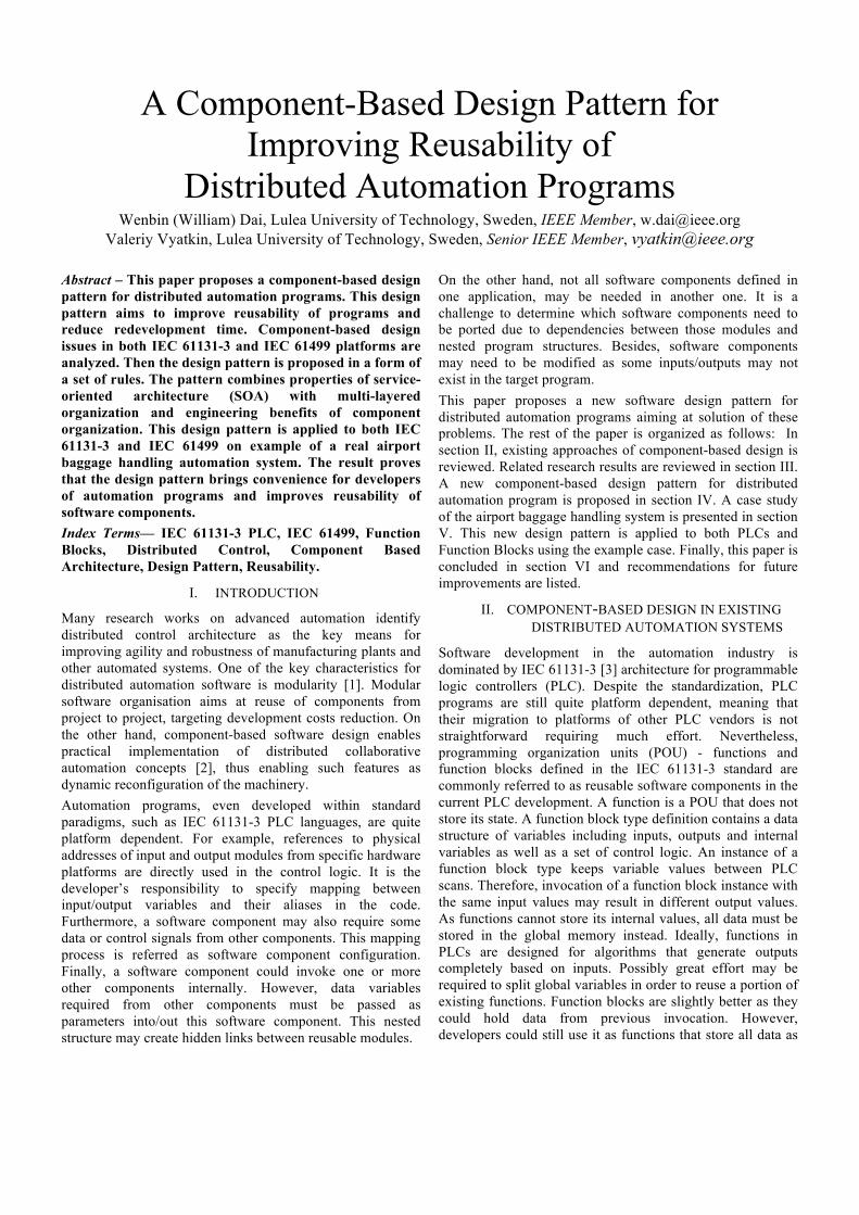
Fig. 6 Reuse Example - Emergency Stop Zone Layout.
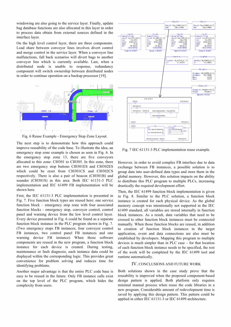
The next step is to demonstrate how this approach could improve reusability of the code base. To illustrate the idea, an emergency stop zone example is chosen as seen in Fig. 6. In the emergency stop zone 13, there are five conveyors allocated to this zone: CI0301 to CI0305. In this zone, there are two emergency stop buttons CI0301ES and CI0302ES which could be reset from CI0301CS and CI0302CS respectively. There is also a pair of beacon (CI0301B) and sounder (CI0301S) in this area. Both IEC 61131-3 PLC implementation and IEC 61499 FB implementation will be shown here. First, the IEC 61131-3 PLC implementation is presented in Fig. 7. Five function block types are reused here: one service function block – emergency stop zone with four associated function blocks - emergency stop, conveyor control, control panel and warning device from the low level control layer. Every device presented in Fig. 6 could be found as a separate function block instance in the PLC program shown in Fig. 7. (Two emergency stops FB instances, four conveyor control FB instances, two control panel FB instances and one warning device FB instance) When those software components are reused in the new program, a function block instance for each device is created. During testing, maintenance or fault diagnosis, each instance data could be displayed within the corresponding logic. This provides great convenience for problem solving and reduces time for identifying problems. Another major advantage is that the entire PLC code base is easy to be reused in the future. Only FB instance calls exist on the top level of the PLC program, which hides the complexity from users.
Fig. 7 IEC 61131-3 PLC implementation reuse example.
However, in order to avoid complex FB interface due to data exchange between FB instances, a possible solution is to group data into user-defined data types and store them in the global memory. However, this solution impacts on the ability to distribute this PLC program to multiple PLCs, increasing drastically the required development effort. Then, the IEC 61499 function block implementation is given in Fig. 8. Similar to the PLC solution, a function block instance is created for each physical device. As the global memory concept was intentionally not supported in the IEC 61499 standard, all variables are stored internally in function block instances. As a result, data variables that need to be crossed to other function block instances must be connected manually. When those function blocks are reused, in addition to creation of function block instances in the target application, event and data connections are also must be established by developers. Mapping this program to multiple devices is much simpler than in PLC case – for that location of each function block instance needs to be specified, the rest of the work will be completed by the IEC 61499 tool and runtime automatically.
IV. CONCLUSIONS AND FUTURE WORK Both solutions shown in the case study prove that the reusability is improved when the proposed component-based design pattern is applied. Both platform only requires minimal manual process when reuse the code libraries in a new program. Considerable amount of redevelopment time is saved by applying this design pattern. This pattern could be applied in either IEC 61131-3 or IEC 61499 architecture.

Fig. 8 IEC 61499 FB implementation reuse example.
For the future work, the design pattern proposed in this paper, can be extended to the full potential of service-oriented architecture. For that, the artifacts of SOA will be modeled using the structures of IEC 61499 standard, including the communication mechanism between different SOA layers. Finally, model-driven code generation [20], [21] could be implemented together with this design pattern in order to fully automate code generation, removing the need for manual code configuration is needed.
ACKNOWLEDGEMENTS The authors are grateful to Glidepath Limited – New Zealand based airport baggage handling system supplier [22] for provision of a real baggage handling system layout diagram for the case study.
REFERENCES [1] K. Trkaj, “Users introduce component based automation solutions”,
Computing & Control Engineering Journal, Vol. 15, Issue 6, Page 32 – 37, 2004.
[2] V. Vyatkin, “IEC 61499 as Enabler of Distributed and Intelligent Automation: State of the Art Review”, IEEE Transactions on Industrial Informatics, 7(4), pp. 768-781, 2011.
[3] IEC 61131-3, Programmable controllers - Part 3: Programming languages, International Standard, Second Edition, 2003
[4] I. B. Pina and L. V. Seisdedos, “Including object-oriented properties in the PLC’s programming languages”, 7th IEEE International Conference on Emerging Technologies and Factory Automation (ETFA), Vol. 2, Page 1029 – 1034, 1999.
[5] M. Bonfe and C. Fantuzzi, “Object-oriented approach to PLC software design for a manufacture machinery using IEC 61131-3 norm languages”, IEEE International Conference on Advanced Intelligent Mechantronics, Vol. 2, Page 787 – 792, 2001.
[6] W. Dai and V. Vyatkin, “Redesign Distributed PLC Control Systems Using IEC 61499 Function Blocks”, IEEE Transactions on Automation Science and Engineering, Vol. 9, Issue 2, Page 390 – 401, 2012.
[7] I. Pina, L. Seisdedos and L. Loperana, “Including object-oriented properties in the PLC’s programming languages”, 7th IEEE
International Conference on Emerging Technologies and Factory Automation (ETFA), Vol 2, Page 1029 – 1034, 1999.
[8] IEC 61499, Function Blocks, International Standard, International Electrotechnical Commission, Geneva, Switzerland, First Edition, 2005.
[9] O. Orozco and J. Lastra, “Adding Function Blocks of IEC 61499 Semantic Description to Automation Objects”, IEEE International Conference on Emerging Technologies and Factory Automation (ETFA), Page 537 – 544, 2006.
[10] W. Lepuschitz and A. Zoitl, “An engineering method for batch process automation using a component oriented design based on IEC 61499”, IEEE International Conference on Emerging Technologies and Factory Automation (ETFA), Page 207 – 214, 2008.
[11] C. Sunder, A. Zoitl, J. Christensen, H. Steininger and J. Rritsche, “Considering IEC 61131-3 and IEC 61499 in the context of component frameworks”, IEEE International Conference on Industrial Informatics (INDIN), Page 277 – 282, 2008.
[12] I. Crnkovic and M. Larsson, “A case study: demands on component-based development”, Proceedings of International Conference on Software Engineering, Page 23 – 31, 2000.
[13] S. Lee, R. Harrison and A. Wes, “A component-based distributed control system for assembly automation”, IEEE International Conference on Industrial Informatics (INDIN), Page 33 – 38, 2004.
[14] H. Park, D. Anh and G. Lee, “Development for automatic control system”, 3rd International Forum on Strategic Technologies, Page 421 – 424, 2008.
[15] X. Kong, B. Ahmad, R. Harrison and L. Lee, “Direct deployment of component-based automation systems”, 17th IEEE International Conference on Emerging Technologies and Factory Automation (ETFA), Page 1 -4, 2012.
[16] G. Black and V. Vyatkin, “Intelligent Component-Based Automation of Baggage Handling Systems with IEC 61499”, IEEE Transactions on Automation Science and Engineering, Vol. 7, Issue 2, Page 337 – 351, 2008.
[17] J. Yan, V. Vyatkin, “Distributed Software Architecture Enabling Peer-to-Peer Communicating Controllers”, IEEE Transactions on Industrial Informatics, 2013, in print
[18] M. Melik-Merkumians, M. Wenger, R. Hametner and A. Zoitl, “Increasing Portability and Reusability of Distributed Control Programs by I/O Access Abstraction”, 15th IEEE International Conference on Emerging Technologies and Factory Automation (ETFA), Page 1 – 4, 2010.
[19] “Hot Backup Application Technique” [Online], Rockwell Automation, available from http://literature.rockwellautomation.com/idc/groups/literature/documents/at/highav-at001_-en-e.pdf
[20] K. Thramboulidis and G. Frey, “Towards a Model-Driven IEC 61131-Based Development Process in Industrial Automation”, Journal of Software Engineering and Applications, Vol. 4, Issue 4, pp. 217–226, 2011.
[21] M. Obermeier, D. Schutz and B. Vogel-Heuser, “Evaluation of a Newly Developed Model-Driven PLC Programming Approach for Machine and Plant Automation”, IEEE International Conference on Systems, Man and Cybernetics, Page 1552 – 1557, 2012.
[22] Glidepath Group [Online, 2003 March] – Airport Baggage Handling System Integrator, http://www.glidepathgroup.com