a complete solution for automating human-intensive part
TRANSCRIPT

3D Robot Vision SystemFH-SMD Series
A complete solution for automating human-intensive part picking

2
Freeing people from monotonous and heavy physical work
The challenges of meeting today's bulk part feeding needsProduction workers are hard to come by these days, and labor costs have risen sharply, putting pressure on manufacturers to automate complex manual processes. Automated systems must continue to identify complex shapes among bulk parts, pick them up, and align them according to feeding types and locations.While many automated part picking solutions fail to achieve human-level speed and flexibility, Omron is making great progress in this area.
3
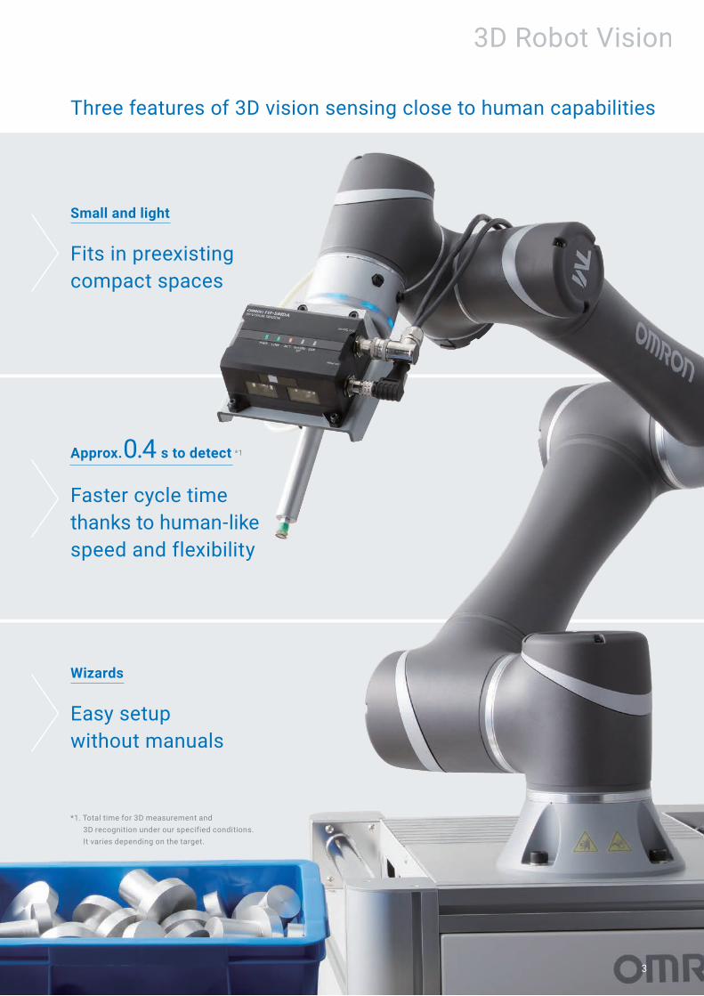
Three features of 3D vision sensing close to human capabilities
3D Robot Vision
*1. Total time for 3D measurement and 3D recognition under our specified conditions. It varies depending on the target.
Small and light
Fits in preexisting compact spaces
Approx. 0.4 s to detect *1
Faster cycle time thanks to human-like speed and flexibility
Easy setup without manuals
Wizards
4
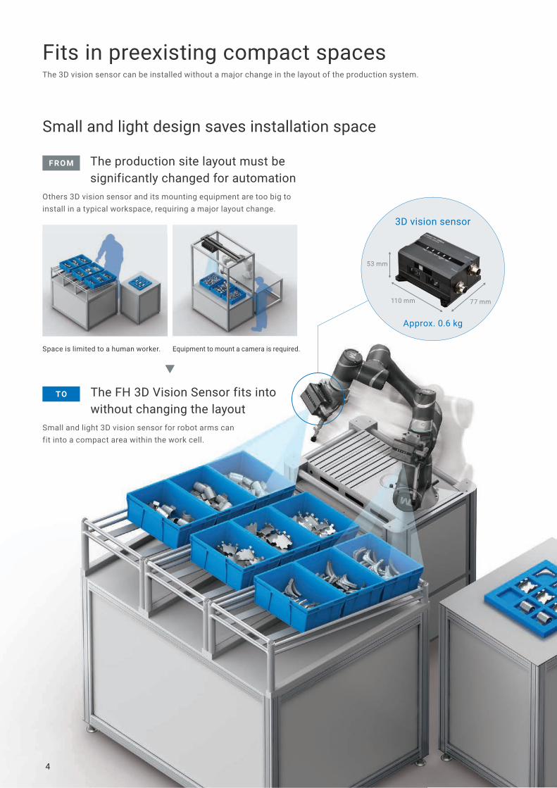
Approx. 0.6 kg
53 mm
77 mm110 mm
Fits in preexisting compact spaces
Small and light design saves installation space
The 3D vision sensor can be installed without a major change in the layout of the production system.
Small and light 3D vision sensor for robot arms can fit into a compact area within the work cell.
The FH 3D Vision Sensor fits into without changing the layout
Others 3D vision sensor and its mounting equipment are too big to install in a typical workspace, requiring a major layout change.
The production site layout must be significantly changed for automation
3D vision sensor
Space is limited to a human worker. Equipment to mount a camera is required.
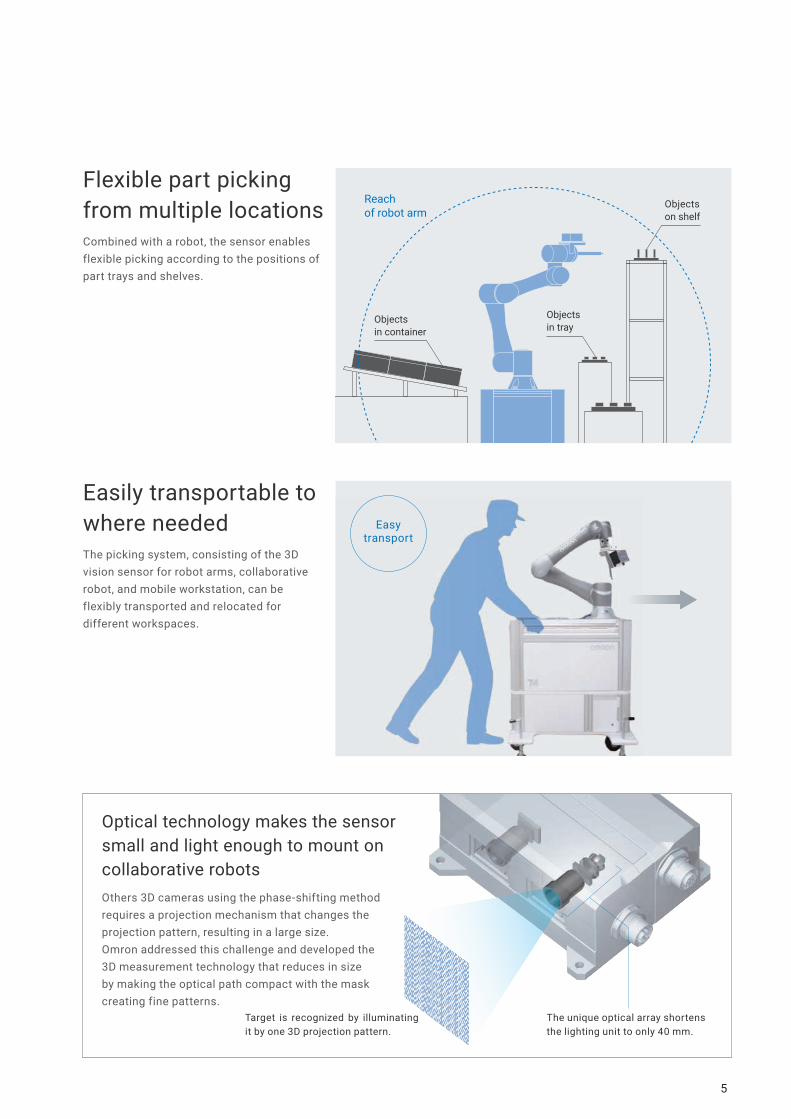
Reach of robot arm
Objects on shelf
Objects in tray
Objects in container
5
Easytransport
Flexible part picking from multiple locations
Easily transportable to where needed
Combined with a robot, the sensor enables flexible picking according to the positions of part trays and shelves.
The picking system, consisting of the 3D vision sensor for robot arms, collaborative robot, and mobile workstation, can be flexibly transported and relocated for different workspaces.
The unique optical array shortens the lighting unit to only 40 mm.
Target is recognized by illuminating it by one 3D projection pattern.
Optical technology makes the sensor small and light enough to mount on collaborative robotsOthers 3D cameras using the phase-shifting method requires a projection mechanism that changes the projection pattern, resulting in a large size.Omron addressed this challenge and developed the 3D measurement technology that reduces in size by making the optical path compact with the mask creating fine patterns.

6
Faster cycle time thanks to human-like speed and flexibilityThe advanced 3D vision sensing technology enables fast and accurate part recognition.
High-speed detection in approximately 0.4 seconds *1 makes picking smooth3D measurement to create 3D shape images and 3D recognition to recognize the position and posture of targets were sped up, which made high-speed part detection possible.
Phase-shiftingmethod
Approx. 3.0 s *2
Considerably increased measurement and recognition speed
Omron’s new method
Approx. 0.4 s
1.0
0.2
2.0
0.2 Measurement time Recognition time

7
There are blind spots where parts cannot be detected.
The camera changes the viewpoint, reducing blind spots.
From above : Cannot detect because the cylindrical part is too small to be detected
From above : Cannot detect because the cylindrical part is too small to be detected
Moved to upper right : Can detect
Breaking the challenge of emptying all bins with less blind spotsThere are blind spots where a fixed camera cannot detect parts inside the bin. To detect these parts, an operator must reposition items in the bin so that the parts are within the field of view. Cameras installed at the robot arms can reduce blind spots by changing the viewpoint, reliably detecting parts without using large-scale equipment.
Fixed camera Camera for robot arms
Phase-shifting methodMultiple shotsMany images need to be captured for measurement while the projection pattern is changed.
3D matching after efficiently narrowing down the area using 2D feature modelSearch and comparison Search Comparison
3D measurement technology for a single-shot measurement
3D recognition technology for improved high-speed 2D search
Omron’s new method searches using small-volume model
*1. Total time for 3D measurement and 3D recognition under our specified conditions. It varies depending on the target. *2. Time measured under our specified conditions is provided for reference.*3. “PATENT PENDING” means that we applied for a patent in Japan, and “PATENTED” means that we obtained a patent in Japan. (As of February 2021)
New technologies enable high-speed detection in approximately 0.4 seconds
Omron’s structured lightOne shotA unique projected pattern image can be captured for measurement.
*3PATENT PENDING
*3
Previous 3D recognition searches using large-volume model
Comprehensive matching using 3D model
PATENTED
8
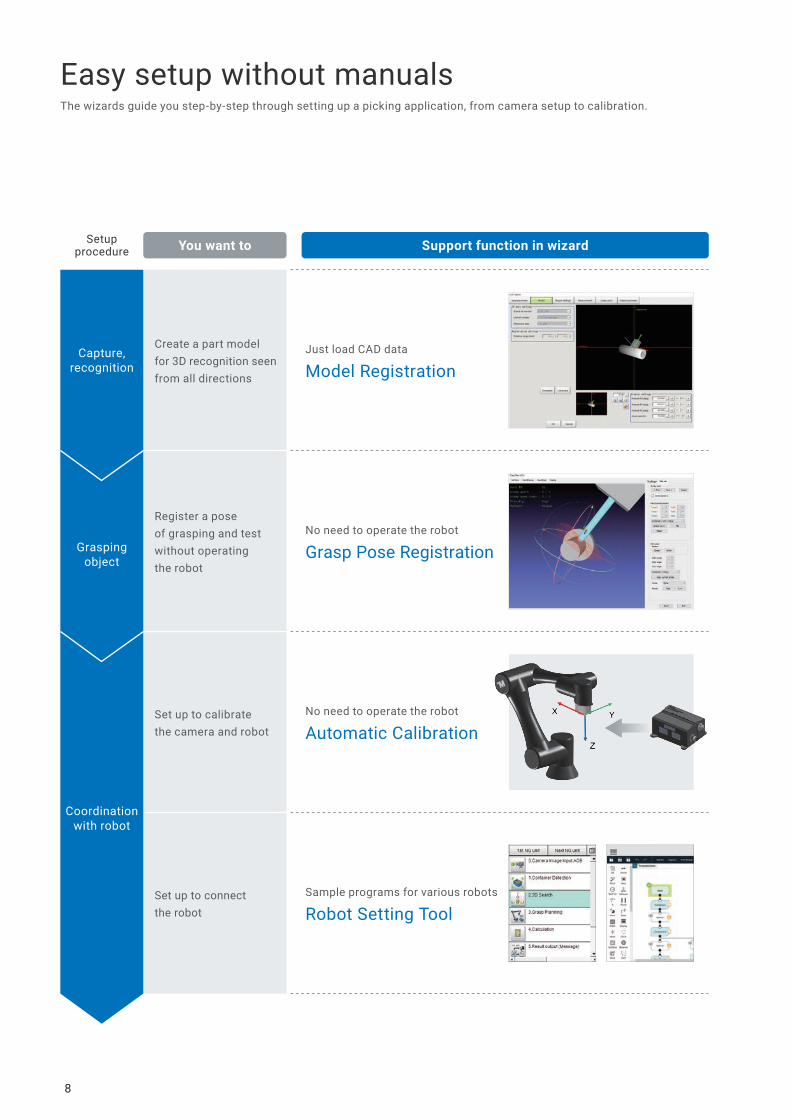
No need to operate the robot
Grasp Pose Registration
No need to operate the robot
Automatic Calibration
Sample programs for various robots
Robot Setting Tool
Just load CAD data
Model Registration
Create a part model for 3D recognition seen from all directions
Register a pose of grasping and test without operating the robot
Set up to calibrate the camera and robot
Set up to connect the robot
You want toSetupprocedure Support function in wizard
Easy setup without manualsThe wizards guide you step-by-step through setting up a picking application, from camera setup to calibration.
Capture,recognition
Graspingobject
Coordinationwith robot
9
Just follow the instructions in the wizards to set approximately 80 parameters required for a picking application, without referring to manuals.
Wizards
Understand the setup procedure and items to enter together with the image of the setup screen.
Click the button at the lower right to display a separate operation window.
Enter the settings while referring to the setup procedure.
Choose one from three items to suit your needs.
In case of Pick Setting
Three items to complete setup
Operation window (displayed in a separate window)
Setup procedure and wizard
Choose
View
Operate
10
Just load CAD data of a part to automatically generate a 3D search model.The CAD data of parts, grasp point data, and hand data can be managed to use for all scenes.When a new product is added, search models of its parts can be generated from the managed CAD data by copying the scene data.
Grasp poses can be set on part's CAD data, which eliminates the need to operate a physical robot.
Grasp poses can be set on 3D graphics Multiple grasp points can be set
Integrated management of CAD data, hand data, and grasp data
Data manager screen
A single click to generate a 3D search model from CAD data
Model registration screen
Model Registration
Grasp Pose Registration
Capture, recognition
Grasping object
Just select
One click to
generate
One click to
display

11
Calibration between the 3D vision sensor and robot can be performed automatically without the need for complicated setup.
Omron provides sample scene data and robot connection programs tailored to individual robots.You can download the Robot Setting Tool for free after purchasing the product and signing up online. For details, see the member registration sheet attached to the 3D Robot Vision Software.
Sample scene data for 3D vision sensor
・For picking application・For hand-eye calibration
Specify the offset position of the 3D vision sensor
Specify the distance between the camera and calibration target
Execute automatic calibration
Result values are displayed
Sample program for robot
・Sample program・Setup program
A sample scene data for the 3D vision sensor and sample program for the robot can be automatically created just by selecting the connected robot.
Automatic Calibration
Robot Setting Tool
Coordination with robot
Coordination with robot
Enter values in only two fields Click a button to automatically calibrate
Robot Setting Tool
Easy to connect

12
System configuration
Omron offers the 3D robot vision system and robots for picking applications.
3D Robot Vision System
Robot
This system recognizes positions and postures of parts and outputs the position information of parts to the robot.
Robots from Omron and other major vendors can be used.
For more information about robots, visit Omron’s website:
http://www.ia.omron.com/tm
Collaborative RobotsTM Series
3D Robot Vision SoftwareYou can use it just by adding it to the sensor controller.・ 3D recognition・ Communications with robots・ Calibration
3D Vision Sensorfor Robot armsFH-SMD Series
Vision SystemFH SeriesFH-5050
TM5X-700
700 mm
6 kg
Reach
Max. payload
TM5X-900
900 mm
4 kg
TM14X
1100 mm
14 kg
TM12X
1300 mm
12 kg
Super-flexible cable ensures long-term stable operationThe new cable offers approximately 10 times *1 the bending resistance of conventional flexible cables. High bending resistance significantly reduces the frequency of replacing the cables on robot arms.
*1. It's compared with the FHV7 Smart Camera flexible cables.
Special material for insulation reduces friction between conductors
Special structure for braided shield and special soft material for outer jacket increase wear resistance
Highly bending-resistant special conductor

13
MEMO
14
3D Robot Vision System
FH-SMD SeriesA complete solution for automating human-intensive part picking• Compact and lightweight weighing approximately 0.6 kg• High-speed detection in approximately 0.4 seconds *1• 3 wizards for easy setup without manuals
System Configuration
*1. Total time for 3D measurement and 3D recognition under our specified conditions. It varies depending on the target.*2. To use STP (shielded twisted-pair) cable of category 5 or higher for Ethernet and RJ45 connector.
PLC for I/O control
Trigger input sensor
NJ/NX/NY-seriesController
(2) Vision System FH Sensor Controller FH-5050
(7) Monitor cableTouch panel cable
(5) Calibration target
(6) Monitor
(3) Camera cable
Robot(1) 3D Vision Sensor FH-SMDA-GS050B
24 VDC power supply
(4) Camera I/O cable
Robot controller
Handeye Calibration TargetFH-XCAL-R
Camera Calibration TargetFH-XCAL-S
HUB (1000BASE)
Ethernet cable *2(9) Ethernet cable *2
(8) Parallel I/O cable
Robot development environment

FH-SMD Series
15
Ordering Information(1) 3D Vision Sensor
(2) Sensor Controller
Note: FH-5050-10 and FH-5050-20 are not applicable.
Software Sold Separately
* This product can be installed on the FH-5050 (version 6.40 or later).
(3) Camera Cables
(4) Camera I/O Cables
Item Model
3D Vision Sensor FH-SMDA-GS050B
Item Model
Sensor Controller FH-5050
Item Model
3D Robot Vision Software Installer * FH-UM3D1
Item Descriptions Cable length Model
Straight Ethernet Cable
3 m FHV-VNBX 3M
5 m FHV-VNBX 5M
10 m FHV-VNBX 10M
Right-angle Ethernet Cable
3 m FHV-VNLBX 3M
5 m FHV-VNLBX 5M
10 m FHV-VNLBX 10M
Item Descriptions Cable length Model
Straight
3 m FH-VSDX-BX 3M
5 m FH-VSDX-BX 5M
10 m FH-VSDX-BX 10M
Right-angle
3 m FH-VSDX-LBX 3M
5 m FH-VSDX-LBX 5M
10 m FH-VSDX-LBX 10M
FH-SMD Series
16
(5) Calibration Targets
(6) Monitor
* FH Series Sensor Controllers version 5.32 or higher is required.
(7) Monitor Cables
A video signal cable and an operation signal cable are required to connect the Touch Panel Monitor.
(8) Parallel I/O Cables
*1. 2 Cables are required for all I/O signals.*2. Insert the cables length into @ in the model number as follows. 2 m = 2, 5 m = 5, 15 m = 15*3. Insert the cables length into @@@ in the model number as follows. 0.5 m = 050, 1 m = 100, 1.5 m = 150, 2 m = 200, 3 m = 300, 5 m = 500*4. Insert the wiring method into @ in the model number as follows. Phillips screw = J, Slotted screw (rise up) = E, Push-in spring = P
Refer to the XW2R Series catalog (Cat. No. G077) for details.
Item Model
Handeye Calibration Target FH-XCAL-R
Camera Calibration Target FH-XCAL-S
Item Descriptions Model
Touch Panel Monitor 12.1 inchesFor FH Sensor Controllers * FH-MT12
LCD Monitor 8.4 inches FZ-M08
Item Descriptions Cable length Model
DVI-Analog Conversion Cable for Touch Panel Monitor/LCD Monitor
2 m FH-VMDA 2M
5 m FH-VMDA 5M
10 m FH-VMDA 10M
RS-232C Cable for Touch Panel Monitor
2 m XW2Z-200PP-1
5 m XW2Z-500PP-1
10 m XW2Z-010PP-1
USB Cable for Touch Panel Monitor2 m FH-VUAB 2M
5 m FH-VUAB 5M
Signal Cable 2 m 5 m 10 mVideo signal DVI-Analog Conversion Cable Yes Yes Yes
Touch panel operation signal
USB Cable Yes Yes No
RS-232C Cable Yes Yes Yes
Item Descriptions Model
Parallel I/O Cable *1Cable length: 2m, 5m or 15m XW2Z-S013-@ *2
Parallel I/O Cable for Connector-terminal Conversion Unit *1Cable length: 0.5 m, 1 m, 1.5 m, 2 m, 3 m, 5 mConnector-Terminal Block Conversion Units can be connected(Terminal Blocks Recommended Products: OMRON XW2R-@34G-T)
XW2Z-@@@EE *3
Connector-Terminal Block Conversion Units, General-purpose devices XW2R-@34GD-T *4
FH-SMD Series
17
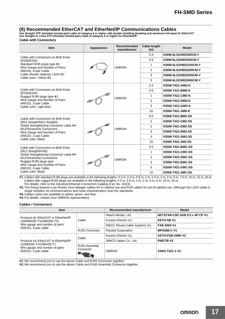
(9) Recommended EtherCAT and EtherNet/IP Communications CablesUse Straight STP (shielded twisted-pair) cable of category 5 or higher with double shielding (braiding and aluminum foil tape) for EtherCAT.Use Straight or cross STP (shielded twisted-pair) cable of category 5 or higher for EtherNet/IP.Cable with Connectors
*1.Cables with standard RJ45 plugs are available in the following lengths: 0.2 m, 0.3 m, 0.5 m, 1 m, 1.5 m, 2 m, 3 m, 5 m, 7.5 m, 10 m, 15 m, 20 m.Cables with rugged RJ45 plugs are available in the following lengths: 0.3 m, 0.5 m, 1 m, 2 m, 3 m, 5 m, 10 m, 15 m.For details, refer to the Industrial Ethernet Connectors Catalog (Cat. No. G019).
*2.The lineup features Low Smoke Zero Halogen cables for in-cabinet use and PUR cables for out-of-cabinet use. Although the LSZH cable is single shielded, its communications and noise characteristics meet the standards.
*3.Cables colors are available in yellow, green, and blue.*4.For details, contact your OMRON representative.
Cables / Connectors
*1.We recommend you to use the above Cable and RJ45 Connector together.*2.We recommend you to use the above Cable and RJ45 Assembly Connector together.
Item Appearance Recommended manufacturer
Cable length (m) Model
Cable with Connectors on Both Ends (RJ45/RJ45)Standard RJ45 plugs type *1Wire Gauge and Number of Pairs: AWG26, 4-pair CableCable Sheath material: LSZH *2Cable color: Yellow *3
OMRON
0.3 XS6W-6LSZH8SS30CM-Y
0.5 XS6W-6LSZH8SS50CM-Y
1 XS6W-6LSZH8SS100CM-Y
2 XS6W-6LSZH8SS200CM-Y
3 XS6W-6LSZH8SS300CM-Y
5 XS6W-6LSZH8SS500CM-Y
Cable with Connectors on Both Ends (RJ45/RJ45)Rugged RJ45 plugs type *1Wire Gauge and Number of Pairs: AWG22, 2-pair CableCable color: Light blue
OMRON
0.3 XS5W-T421-AMD-K
0.5 XS5W-T421-BMD-K
1 XS5W-T421-CMD-K
2 XS5W-T421-DMD-K
5 XS5W-T421-GMD-K
10 XS5W-T421-JMD-K
Cable with Connectors on Both Ends (M12 Straight/M12 Straight)Shield Strengthening Connector cable *4M12/Smartclick ConnectorsWire Gauge and Number of Pairs: AWG22, 2-pair CableCable color: Black
OMRON
0.5 XS5W-T421-BM2-SS
1 XS5W-T421-CM2-SS
2 XS5W-T421-DM2-SS
3 XS5W-T421-EM2-SS
5 XS5W-T421-GM2-SS
10 XS5W-T421-JM2-SS
Cable with Connectors on Both Ends (M12 Straight/RJ45)Shield Strengthening Connector cable *4M12/Smartclick ConnectorsRugged RJ45 plugs typeWire Gauge and Number of Pairs: AWG22, 2-pair CableCable color: Black
OMRON
0.5 XS5W-T421-BMC-SS
1 XS5W-T421-CMC-SS
2 XS5W-T421-DMC-SS
3 XS5W-T421-EMC-SS
5 XS5W-T421-GMC-SS
10 XS5W-T421-JMC-SS
Item Recommended manufacturer Model
Products for EtherCAT or EtherNet/IP (1000BASE-T/100BASE-TX)Wire gauge and number of pairs: AWG24, 4-pair cable
Cable
Hitachi Metals, Ltd. NETSTAR-C5E SAB 0.5 x 4P CP *1
Kuramo Electric Co. KETH-SB *1
SWCC Showa Cable Systems Co. FAE-5004 *1
RJ45 Connector Panduit Corporation MPS588-C *1
Products for EtherCAT or EtherNet/IP (100BASE-TX/10BASE-T)Wire gauge and number of pairs: AWG22, 2-pair cable
CableKuramo Electric Co. KETH-PSB-OMR *2
JMACS Japan Co., Ltd. PNET/B *2
RJ45 Assembly Connector OMRON XS6G-T421-1 *2

FH-SMD Series
18
AccessoriesItem Descriptions Model
USB Memory2 GB FZ-MEM2G
8 GB FZ-MEM8G
SD Card2 GB HMC-SD291
4 GB HMC-SD491
Display/USB Switcher FZ-DU
---Mouse Recommended ProductsDriverless wired mouse(A mouse that requires the mouse driver to be installed is not supported.)
---
EtherCAT junction slaves
3 portPower supply voltage:20.4 to 28.8 VDC(24 VDC -15 to 20%)
Current consumption:0.08 A GX-JC03
6 port Current consumption:0.17 A GX-JC06
Industrial Switching Hubs for EtherNet/IP and Ethernet
3 port Failure detection: None Current consumption:0.08 A W4S1-03B
5 port Failure detection: NoneCurrent consumption:0.12 A
W4S1-05B
5 port Failure detection: Supported W4S1-05C

FH-SMD Series
19
Ratings and Specifications3D Vision Sensor
*1.Existing the third class groundingNote: 1. This camera cannot be used as a measuring instrument, because it is not an absolute distance. Use in combination with robot calibration.
Model FH-SMDA-GS050B
Image elements CMOS image elements
Color/Monochrome Monochrome
Effective pixels 1296 (H) x 972 (V)
Shutter function Electronic shutter, Shutter speeds can be set from 1 ms to 50 ms.
Measurement range (X,Y,Z) 400 x 300 x 200 mm
Installation distance WD: 400 mm
Lighting for 2DLighting color blue
LED class Group 2 (IEC62471)
Lighting for 3DLighting color blue
LED class Group 2 (IEC62471)
Indicator Lamps
PWR: GreenLINK: GreenACT: YellowWARM UP: YellowERR: Red
External I/FFH controller connection
GigE (1000BASE-T) x 1100Base cannot be used.PoE is not available.
Power supply, Input / output
Power supply: 24 VDCI/O: -
Warming up time 15 minutes or less
Supply Voltage 21.6 VDC to 26.4 VDC (24 VDC ± 10%)
Current consumption 2A max.
Vibration tolerance Oscillation frequency: 10 to 150 Hz, Half amplitude: 0.35 mm, Sweep time: 8 minute/count, Sweep count: 10, Vibration direction: X/Y/Z
Shock resistance Impact force: 150 m/s2, Test direction: up and down/front and behind/left and right
Ambient temperature range Operating: 0°C to +40°CStorage: -25 to +60°C (with no icing or condensation)
Ambient humidity range Operating and storage: 35 to 85% (with no condensation)
Ambient atmosphere No corrosive gases
Grounding Class D grounding (100 Ω or less grounding resistance) *1
Dimensions 53 mm x 110 mm x 77 mm (Excluding protrusions and connectors)
Degree of protection IEC60529 IP60
Material Aluminium (A5052)
Weight Approx. 570 g
Accessories Instruction SheetGeneral Compliance Information and Instructions for EU
FH-SMD Series
20
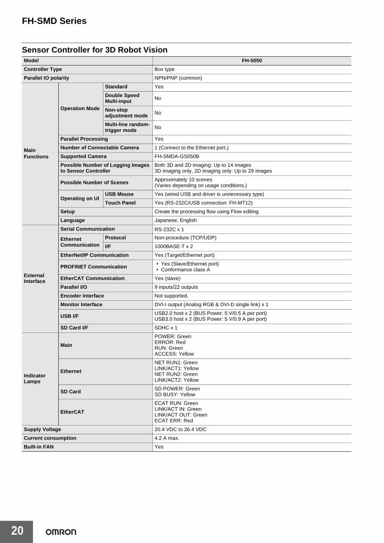
Sensor Controller for 3D Robot VisionModel FH-5050
Controller Type Box type
Parallel IO polarity NPN/PNP (common)
Main Functions
Operation Mode
Standard Yes
Double Speed Multi-input No
Non-stop adjustment mode No
Multi-line random-trigger mode No
Parallel Processing Yes
Number of Connectable Camera 1 (Connect to the Ethernet port.)
Supported Camera FH-SMDA-GS050B
Possible Number of Logging Images to Sensor Controller
Both 3D and 2D imaging: Up to 14 images3D imaging only, 2D imaging only: Up to 29 images
Possible Number of Scenes Approximately 10 scenes (Varies depending on usage conditions.)
Operating on UIUSB Mouse Yes (wired USB and driver is unnecessary type)
Touch Panel Yes (RS-232C/USB connection: FH-MT12)
Setup Create the processing flow using Flow editing.
Language Japanese, English
External Interface
Serial Communication RS-232C x 1
Ethernet Communication
Protocol Non-procedure (TCP/UDP)
I/F 1000BASE-T x 2
EtherNet/IP Communication Yes (Target/Ethernet port)
PROFINET Communication • Yes (Slave/Ethernet port)• Conformance class A
EtherCAT Communication Yes (slave)
Parallel I/O 9 inputs/22 outputs
Encoder Interface Not supported.
Monitor Interface DVI-I output (Analog RGB & DVI-D single link) x 1
USB I/F USB2.0 host x 2 (BUS Power: 5 V/0.5 A per port)USB3.0 host x 2 (BUS Power: 5 V/0.9 A per port)
SD Card I/F SDHC x 1
Indicator Lamps
Main
POWER: GreenERROR: RedRUN: GreenACCESS: Yellow
Ethernet
NET RUN1: GreenLINK/ACT1: YellowNET RUN2: GreenLINK/ACT2: Yellow
SD Card SD POWER: GreenSD BUSY: Yellow
EtherCAT
ECAT RUN: GreenLINK/ACT IN: GreenLINK/ACT OUT: GreenECAT ERR: Red
Supply Voltage 20.4 VDC to 26.4 VDC
Current consumption 4.2 A max.
Built-in FAN Yes

FH-SMD Series
21
*1.Existing the third class grounding
Usage Environment
Ambient temperature range Operating: 0°C to +45°CStorage: -20 to +65°C (with no icing or condensation)
Ambient humidity range Operating and storage: 35 to 85% (with no condensation)
Ambient atmosphere No corrosive gases
Vibration toleranceOscillation frequency: 10 to 150 Hz, Half amplitude: 0.1 mm, Acceleration: 15 m/s2
Sweep time: 8 minute/count, Sweep count: 10, Vibration direction: up and down/front and behind/left and right
Shock resistance Impact force: 150 m/s2
Test direction: up and down/front and behind/left and right
Noise immunity Fast Transient Burst
• DC power:Direct infusion: 2 kV, Pulse rising: 5 ns, Pulse width: 50 ns, Burst continuation time: 15 ms/0.75 ms, Period: 300 ms, Application time: 1 min.
• I/O line:Direct infusion: 1 kV, Pulse rising: 5 ns, Pulse width: 50 ns, Burst continuation time: 15 ms/0.75 ms, Period: 300 ms, Application time: 1 min.
Grounding Class D grounding (100 Ω or less grounding resistance) *1
External Features
Dimensions 190 mm x 115 mm x 182.5 mmNote: Height: Including the rubber at the base.
Weight Approx. 3.4 kg
Degree of protection IEC60529 IP20
Case material Cover: zinc-plated steel plate, Side plate: aluminum (A6063)
Accessories
Instruction Sheet (Japanese and English): 1, Installation Instruction Manual for FH series: 1,General Compliance Information and Instructions for EU: 1, Member registration sheet: 1, Power source (FH-XCN): 1 (male),Ferrite core for camera cable: 2
Model FH-5050
FH-SMD Series
22
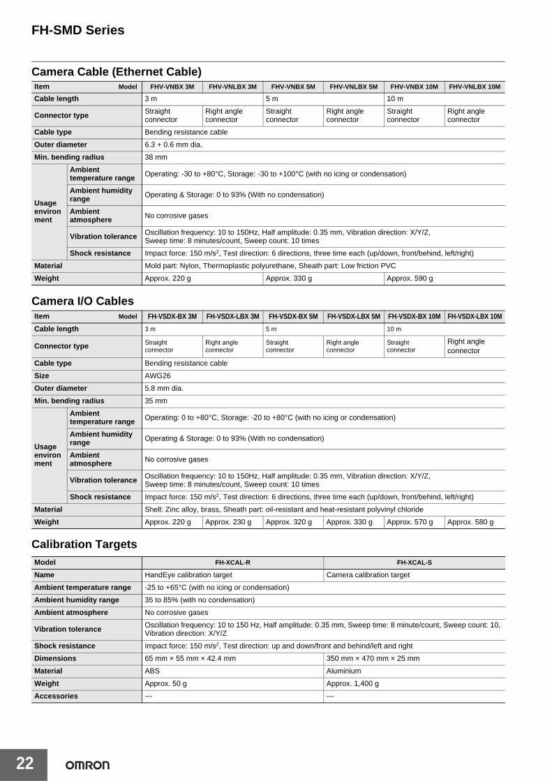
Camera Cable (Ethernet Cable)
Camera I/O Cables
Calibration Targets
Item Model FHV-VNBX 3M FHV-VNLBX 3M FHV-VNBX 5M FHV-VNLBX 5M FHV-VNBX 10M FHV-VNLBX 10M
Cable length 3 m 5 m 10 m
Connector type Straight connector
Right angle connector
Straight connector
Right angleconnector
Straight connector
Right angleconnector
Cable type Bending resistance cable
Outer diameter 6.3 + 0.6 mm dia.
Min. bending radius 38 mm
Usage environment
Ambient temperature range Operating: -30 to +80°C, Storage: -30 to +100°C (with no icing or condensation)
Ambient humidity range Operating & Storage: 0 to 93% (With no condensation)
Ambient atmosphere No corrosive gases
Vibration tolerance Oscillation frequency: 10 to 150Hz, Half amplitude: 0.35 mm, Vibration direction: X/Y/Z, Sweep time: 8 minutes/count, Sweep count: 10 times
Shock resistance Impact force: 150 m/s2, Test direction: 6 directions, three time each (up/down, front/behind, left/right)
Material Mold part: Nylon, Thermoplastic polyurethane, Sheath part: Low friction PVC
Weight Approx. 220 g Approx. 330 g Approx. 590 g
Item Model FH-VSDX-BX 3M FH-VSDX-LBX 3M FH-VSDX-BX 5M FH-VSDX-LBX 5M FH-VSDX-BX 10M FH-VSDX-LBX 10M
Cable length 3 m 5 m 10 m
Connector type Straight connector
Right angleconnector
Straight connector
Right angleconnector
Straight connector
Right angleconnector
Cable type Bending resistance cable
Size AWG26
Outer diameter 5.8 mm dia.
Min. bending radius 35 mm
Usage environment
Ambient temperature range Operating: 0 to +80°C, Storage: -20 to +80°C (with no icing or condensation)
Ambient humidity range Operating & Storage: 0 to 93% (With no condensation)
Ambient atmosphere No corrosive gases
Vibration tolerance Oscillation frequency: 10 to 150Hz, Half amplitude: 0.35 mm, Vibration direction: X/Y/Z, Sweep time: 8 minutes/count, Sweep count: 10 times
Shock resistance Impact force: 150 m/s2, Test direction: 6 directions, three time each (up/down, front/behind, left/right)
Material Shell: Zinc alloy, brass, Sheath part: oil-resistant and heat-resistant polyvinyl chloride
Weight Approx. 220 g Approx. 230 g Approx. 320 g Approx. 330 g Approx. 570 g Approx. 580 g
Model FH-XCAL-R FH-XCAL-S
Name HandEye calibration target Camera calibration target
Ambient temperature range -25 to +65°C (with no icing or condensation)
Ambient humidity range 35 to 85% (with no condensation)
Ambient atmosphere No corrosive gases
Vibration tolerance Oscillation frequency: 10 to 150 Hz, Half amplitude: 0.35 mm, Sweep time: 8 minute/count, Sweep count: 10, Vibration direction: X/Y/Z
Shock resistance Impact force: 150 m/s2, Test direction: up and down/front and behind/left and right
Dimensions 65 mm × 55 mm × 42.4 mm 350 mm × 470 mm × 25 mm
Material ABS Aluminium
Weight Approx. 50 g Approx. 1,400 g
Accessories --- ---

FH-SMD Series
23
Touch Panel Monitor
Note: FH Series Sensor Controllers version 5.32 or higher is required.
Monitor Cables
LCD Monitor
Model FH-MT12
Major Function
Display area 12.1 inch
Resolution 1024 (V) × 768 (H)
Number of color 16,700,000 colors (8 bit/color)
Brightness 500cd/m2 (Typ)
Contrast Ratio 600:1 (Typ)
Viewing angle Left and right: each 80°, upward: 80°, downward: 60°
Backlight Unit LED, edge-light
Backlight lifetime About 100,000 hour
Touch panel 4 wire resistive touch screen
External interface
Video input analog RGB
Touch panel signalUSB
RS-232C
Ratings
Power supply voltage 24 VDC (21.6 to 26.4 VDC)
Current consumption 0.5 A
Insulation resistance Between DC power supply and Touch Panel Monitor FG: 20 MΩ or higher (rated voltage 250 V)
Operating environment
Ambient temperature range Operating: 0 to 50°C, Storage: -20 to +65°C (with no icing or condensation)
Ambient humidity range Operating and Storage: 20 to 90%RH (with no icing or condensation)
Ambient environment No corrosive gas
Vibration resistance 10 to 150 Hz, one-side amplitude 0.1 mm (Max. acceleration 15 m/s2)10 times for 8 minutes for each three direction
Degree of protection Panel mounting: IP65 on the front
Operation Touch pen
Structure
Mounting Panel mounting, VESA mounting
Weight Approx. 2.6 kg
Material Front panel: PC/PBT, Front Sheet: PET, Rear case: SUS
Model FH-VMDA (2 m) FH-VUAB (2 m) XW2Z-200PP-1 (2 m)
Cable type DVI-Analog Conversion Cable USB Cable RS-232C Cable
Vibration resistance 10 to 150 Hz, one-side amplitude 0.1 mm, 10 times for 8 minutes for each three direction
Ambient Temperature Operating Condition: 0 to 50°C, Storage Condition: -10 to 60°C (with no icing or condensation)
Ambient Humidity Operating Condition: 35 to 85%RH, Storage Condition: 35 to 85%RH (with no icing or condensation)
Ambient environment No corrosive gases
Material Cable outer sheath, Connector: PVC Cable outer sheath: PVC, Connector: ABS/Ni Plating
Minimum bend radius 36 mm 25 mm 59 mm
Weight Approx. 220 g Approx. 75 g Approx. 162 g
Model FZ-M08
Size 8.4 inches
Type Liquid crystal color TFT
Resolution 1,024 × 768 dots
Input signal Analog RGB video input, 1 channel
Power supply voltage 21.6 to 26.4 VDC
Current consumption Approx. 0.7 A max.
Ambient temperature range Operating: 0 to 50 °C; Storage: -25 to 65 °C (with no icing or condensation)
Ambient humidity range Operating and storage: 35 to 85% (with no condensation)
Weight Approx. 1.2 kg
Accessories Instruction Sheet and 4 mounting brackets

FH-SMD Series
24
EtherCAT Communications Specifications
* This depends on the upper limit of the master.
Item Specifications
Communications standard IEC61158 Type 12
Physical layer 100 BASE-TX (IEEE802.3)
Modulation Base band
Baud rate 100 Mbps
Topology Depends on the specifications of the EtherCAT master.
Transmission Media Twisted-pair cable of category 5 or higher (double-shielded straight cable with aluminum tape and braiding)
Transmission Distance Distance between nodes: 100 m or less
Node address setting 00 to 99
External connection terminals RJ45 × 2 (shielded) IN: EtherCAT input data, OUT: EtherCAT output data
Send/receive PDO data sizes
Input 56 to 280 bytes/line (including input data, status, and unused areas) Up to 8 lines can be set. *
Output 28 bytes/line (including output data and unused areas) Up to 8 lines can be set. *
Mailbox data sizeInput 512 bytes
Output 512 bytes
Mailbox Emergency messages, SDO requests, and SDO information
Refreshing methods I/O-synchronized refreshing (DC)

FH-SMD Series
25
Components and Functions3D Vision Sensor
Name Description
1 2D lighting unit Lighting for 2D measurement is arranged to illuminate the light.
2 3D lighting unit Pattern lighting for 3D measurement is arranged to illuminate the light.
3 Imaging unit Captures images.
4 Connector for camera I/O cable Use this connector when connecting the camera with a power supply using a camera I/O cable.Dedicated camera I/O cable: FH-VSDX-BX / FH-VSDX-LBX)
5 Connector for camera cable (Ethernet cable)
Use this connector when connecting the camera with a FH sensor controller using an camera cable (Ethernet cable).Dedicated camera cable (Ethernet cable): FHV-VNBX / FHV-VNLBX)
6 Operation indicator
PWR (Green) Lights while power is supplied.
LINK (Green) Lights when connected with Ethernet equipment.
ACT (Yellow) Blinks while communicating with an Ethernet device.
WARM UP (Yellow) Lights from startup to completion of warming up. Turns off after warming up.
ERR (Red)Lights when an error occurs.For the error (system error), refer to the Camera Image Input AOS in the Vision System FH series Processing Item Function Reference Manual for 3D Robot Vision (Cat. No. Z445).
1
2
35
4
6

FH-SMD Series
26
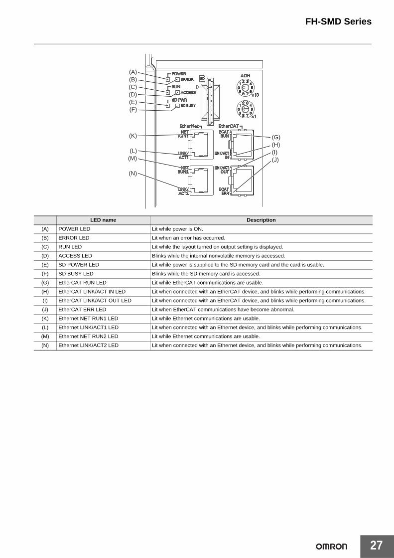
Sensor Controller
Connector name Description
(A) SD memory card installation connector
Install the SD memory card. Do not plug or unplug the SD memory card during measurement operation. Otherwise measurement time may be affected or data may be destroyed.
(B) Ethernet connector
Connect an Ethernet device.
Connect the camera cable (Ethernet cable FHV-VN@BX: sold separately) to the upper port.
(C) USB connector
Connect a USB device.Do not plug or unplug it during measurement. Otherwise measurement time may be affected or data may be destroyed.
(D) RS-232C connector Connect an external device such as a touch panel monitor.
(E) DVI-I connector Connect a monitor.
(F) I/O (Parallel) connector (control lines, data lines) Connect the controller to external devices such as a sync sensor and PLC.
(G) EtherCAT address setup volume Used to set a station address (00 to 99) as an EtherCAT communication device.
(H) EtherCAT communication connector (IN) Connect the opposed EtherCAT device.
(I) EtherCAT communication connector (OUT) Connect the opposed EtherCAT device.
(J) Encoder connector Not supported.
(K) Camera connector Not supported. Do not connect cameras.
(L) Power supply terminal connectorConnect a DC power supply. Wire the FH Sensor Controller independently on other devices.Wire the ground line. Be sure to ground the FH Sensor Controller alone.Use an attachment power terminal (male) for installation.
(A)
(B)
(C)
(D)
(E)(F)
(G)
(H)
(I)
(K)
(L)
(J)
Upper port : Ethernet portLower port : Ethernet port, EtherNet/IP port, and PROFINET port are sharing use.
Left ports: USB2.0Right ports: USB3.0
The USB3.0 interface has a higher bus power supply capability than the USB2.0 interface, and you can expect more stable operation with it.
Also, when used in combination with a USB3.0 device, you can expect higher transfer speed than USB2.0.Be sure to give priority to using the USB3.0 interface.
FH-SMD Series
27
LED name Description
(A) POWER LED Lit while power is ON.
(B) ERROR LED Lit when an error has occurred.
(C) RUN LED Lit while the layout turned on output setting is displayed.
(D) ACCESS LED Blinks while the internal nonvolatile memory is accessed.
(E) SD POWER LED Lit while power is supplied to the SD memory card and the card is usable.
(F) SD BUSY LED Blinks while the SD memory card is accessed.
(G) EtherCAT RUN LED Lit while EtherCAT communications are usable.
(H) EtherCAT LINK/ACT IN LED Lit when connected with an EtherCAT device, and blinks while performing communications.
(I) EtherCAT LINK/ACT OUT LED Lit when connected with an EtherCAT device, and blinks while performing communications.
(J) EtherCAT ERR LED Lit when EtherCAT communications have become abnormal.
(K) Ethernet NET RUN1 LED Lit while Ethernet communications are usable.
(L) Ethernet LINK/ACT1 LED Lit when connected with an Ethernet device, and blinks while performing communications.
(M) Ethernet NET RUN2 LED Lit while Ethernet communications are usable.
(N) Ethernet LINK/ACT2 LED Lit when connected with an Ethernet device, and blinks while performing communications.
(A)(B)(C)(D)(E)(F)
(G)(H)(I)(J)
(K)
(L)(M)
(N)

FH-SMD Series
28
Processing Items
Group Icon Processing Item
Measure-ment
3D Search
Using CAD data of the workpiece, this pro-cessing item registers information on surfac-es and contours that are seen from various viewpoints as a model, and then detects the position/posture of a workpiece that is most similar to the model based on the input depth map and input image. (For 3D robot vision)
Container Detection
Defines a 3D container model for detecting collision of the hand model. (For 3D robot vi-sion)
Grasp PlanningPerforms operations to enable the robot connected to the FH-series Sensor Control-ler to grasp the detected object. (For 3D ro-bot vision)
Search Used to identify the shapes and calculate the position of measurement objects.
Search IIEven if the Search processing item cannot de-tect a model, the Search II can stably detect it by creating the optimal model according to the size and rotation of the measurement object.
Flexible Search Recognizing the shapes of workpieces with variation and detecting their positions.
Sensitive SearchSearch a small difference by dividing the search model in detail, and calculating the correlation.
Shape Search III
Robust detection of positions is possible at high-speed and with high precision incorpo-rating environmental fluctuations, such as differences in individual shapes of the work-pieces, pose fluctuations, noise superimpo-sition and shielding.
ClassificationUsed when various kinds of products on the assembly line need to be sorted and identi-fied.
Edge PositionMeasure position of measurement objects according to the color change in measure-ment area.
Edge PitchDetect edges by color change in measure-ment area. Used for calculating number of pins of IC and connectors.
Scan Edge Position
Measure peak/bottom edge position of workpieces according to the color change in separated measurement area.
Scan Edge Width
Measure max/min/average width of work-pieces according to the color change in sep-arated measurement area.
Circular Scan Edge Position
Measure center axis, diameter and radius of circular workpieces.
Circular Scan Edge Width
Measure center axis, width and thickness of ring workpieces.
IntersectionCalculate approximate lines from the edge information on two sides of a square work-piece to measure the angle formed at the in-tersection of the two lines.
Color DataUsed for detecting presence and mixed va-rieties of products by using color average and deviation.
Gravity and AreaUsed to measure area, center of gravity of workpices by extracting the color to be mea-sured.
Labeling Used to measure number, area and gravity of workpieces by extracting registered color.
Precise Defect Check the defect on the object. Parameters for extraction defect can be set precisely.
Fine MatchingDifference can be detected by overlapping and comparing (matching) registered fine images with input images.
Character Inspect
Recognize character according correlation search with model image registered in [Mod-el Dictionary].
Date Verification Reading character string is verified with in-ternal date.
Model DictionaryRegister character pattern as dictionary. The pattern is used in [Character Inspec-tion].
2DCode II *1 Recognize 2D code and display where the code quality is poor.
2DCode *2 Recognize 2D code and display where the code quality is poor.
Barcode *3 Recognize barcode, verify and output de-coded characters.
OCR Recognize and read characters in images as character information.
OCR User Dictionary Register dictionary data to use for OCR.
Glue Bead Inspection
You can inspect coating of a specified color for gaps or runoffs along the coating path.
Input Image
Camera Image Input AOS *4
Loads images from the camera. (For 3D robot vision)
Measurement Image Switching
To switch the images used for measure-ment. Not input images from camera again.
Compensateimage
Position Com-pensation
Used when positions are differed. Correct measurement is performed by correcting po-sition of input images.
FilteringUsed for processing images input from cam-eras in order to make them easier to be measured.
Background Suppression
To enhance contrast of images by extracting color in specified brightness.
Brightness Correct Filter
Track brightness change of entire screen and remove gradual brightness change such as uneven brightness.
Color Gray Filter Color image is converted into monochrome images to emphasize specific color.
Extract Color Filter
Convert color image to color extracted im-age or binary image.
Anti Color Shading
To remove the irregular color/pattern by uni-formizing max.2 specified colors.
Stripes Removal Filter II
Remove the background pattern of vertical, horizontal and diagonal stripes.
Polar Transformation
Rectify the image by polar transformation. Useful for OCR or pattern inspection printed on circle.
Trapezoidal Correction Rectify the trapezoidal deformed image.
Image Subtrac-tion
The registered model image and measure-ment image are compared and only the dif-ferent pixels are extracted and converted to an image.
Advanced filter
Process the images acquired from cameras in order to make them easier to measure. This processing item consolidates existing image conversion filtering into one process-ing item and adds extra functions.
Supportmeasure-ment
3D Data Manag-er
Manages the CAD data, hand data, and grasp pose data (grasp DB data) required for picking applications. (For 3D robot vi-sion)
Camera Calibration AOS *4
Calibrates the camera (3D vision sensor) using a dedicated calibration plate. (For 3D robot vision)
HandEye Calibration
Calibrates the robot hand and camera (eye) to maintain the relationship of installation. (For3D robot vision)
Unit MacroAdvanced arithmetic processing can be easily incorporated into workflow as Unit Macro processing items.
Unit Calculation Macro
This function is convenient when the user wants to calculate a value using an original calculation formula or change the set value or system data of a processing item.
CalculationUsed when using the judge results and mea-sured values of ProcItem which are regis-tered in processing units.
Line Regression Used for calculating regression line from plural measurement coodinate.
Circle Regression
Used for calculating regression circle from plural measurement coordinate.
Trend MonitorUsed for displaying the information about re-sults on the monitor, facilitating to avoid NG and analyze causes.
Image Logging Used for saving the measurement images to the memory and USB memory.
Image Conver-sion Logging
Used for saving the measurement images in JPEG and BMP format.
Elapsed Time Used for calculating the elapsed time since the measurement trigger input.
Wait Processing is stopped only at the set time. The standby time is set by the unit of [ms].
Focus Focus setting is supported.
Iris Focus and aperture setting is supported.
Statistics Used when you need to calculate an aver-age of multiple measurement results.
Robot Data Sets and stores data related to robots.
Data SaveThe set data can be saved in the controller main unit or as scene data. The data is held even after the FH/FZ power is turned off.
Scene The specified scene is copied to the current scene.
System Information
Obtain system information (e.g., memory and disk space and I/O input signal status) of the Sensor Controller.
Group Icon Processing Item

FH-SMD Series
29
*1. 2D Codes that can be read: Data Matrix (ECC200)*2. 2D Codes that can be read: Data Matrix (ECC200), QR Code*3. Bar Codes that can be read: JAN/EAN/UPC (including add-on codes),
Code 39, Codabar (NW-7), ITF (Interleaved 2 of 5), Code 93, Code 128, GS1-128, GS1 DataBar (RSS-14 / RSS Limited / RSS Expanded), Pharmacode
*4. AOS: Active One Shot
Branch
End This ProcItem must be set up as the last pro-cessing unit of a branch.
Conditional Execution (If)
The measurement flow is divided according to the comparison result obtained using the set expressions and conditions.
Conditional Execution (Else)
Insert between the Conditional Execution (If) processing item and End If processing item. The measurement flow is divided ac-cording to the comparison result obtained using the set expressions and conditions.
LoopThe set processes are repeated until the loop count reaches the specified number, and then the next process starts.
Loop Suspen-sion
Insert between the Loop processing item and End Loop processing item. Used to stop the loop before the loop count reaches the specified number.
Select Execution (Select)
Used to set conditions. The measurement flow is divided according to the comparison result obtained using the conditions given by expressions.
Select Execution (Case)
Used to make a judgment. The measure-ment flow is divided according to the com-parison result obtained using the conditions given by expressions.
Output result
Result Output (I/O)
Output data to the external devices such as a programmable controller or a PC via PLC Link, Parallel interface, Fieldbus interface (EtherCAT, EtherNet/IP (other than mes-sage communication), PROFINET).
Result Output (Message)
Output data to the external devices such as a programmable controller or a PC with non-procedure mode via the serial interface or EtherNet/IP (message communication). This processing item allows you to save the logging data as a “.csv” file into the Sensor Controller as well.
Result Output (Parallel I/O)
Output measurement results and/or judg-ment results to the external devices such as a programmable controller or a PC via Par-allel interface.
Display result
Result Display Used for displaying the texts or the figures in the camera image.
Display Last NG Image Display the last NG images.
Display Image Hold
Processing item to retain images, including measurement results.
Group Icon Processing Item
FH-SMD Series
30
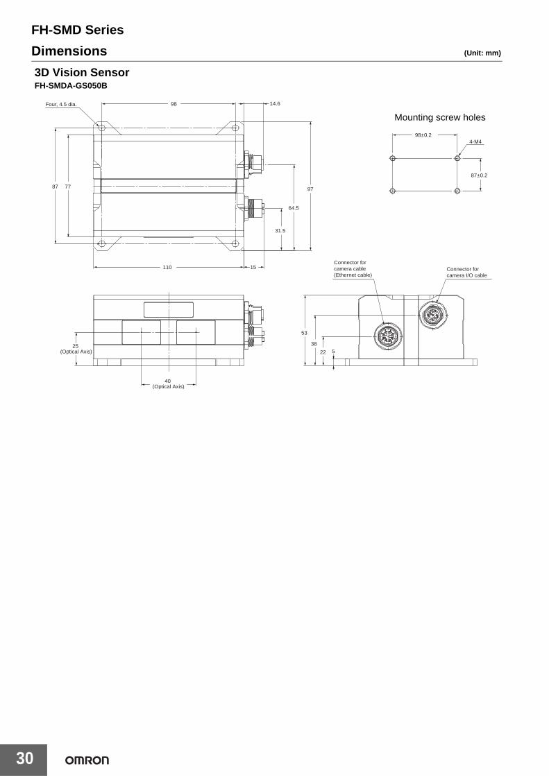
Dimensions (Unit: mm)
110
25 (Optical Axis)
14.698Four, 4.5 dia.
7787 97
Mounting screw holes
98±0.2
Connector for camera I/O cable
Connector for camera cable (Ethernet cable)
38
22 5
53
87±0.2
4-M4
64.5
31.5
15
40 (Optical Axis)
3D Vision SensorFH-SMDA-GS050B

FH-SMD Series
31
19.5143 115
2414
1
19.2 143182.5
2414
119
0
20.1
26.7 148.5
10.5
94
66.2
38.1
Four, M4 mounting holeswith a depth of 4.5 mm
Four, M4 mounting holes with a depth of 4.5 mm
Four, M3 mounting holes with a depth of 4.5 mm
Sensor ControllerFH-5050
58.3 53.5
21.0
M12
.0x1
.0
16.1
dia
.
6.3 dia.
14.6
dia
.
L *
5.0
* Cable is available in 3 m/5 m/10 m.
Camera cable (Ethernet cable, Straight)FHV-VNBX @M
L * 46.0 53.5
15 dia.
6.3 dia. 5.0
21.
0 42.
2
R8.0
M12×1.0
* Cable is available in 3 m/5 m/10 m.
Camera cable (Ethernet cable, Right-angle)FHV-VNLBX @M
55±5L
30
(5)(50)
(Brown)(Blue)
(Green)(Shield)
* Cable lengths (L) are 3 m/5 m/10 m.
Camera I/O Cables (Straight)FH-VSDX-BX @M
55±5L
30
(5)(50)
(Brown)(Blue)
(Green)(Shield)
* Cable lengths (L) are 3 m/5 m/10 m.
Camera I/O Cables (Right-angle)FH-VSDX-LBX @M

FH-SMD Series
32
Calibration Targets
17
5
65
42.4
20 dia.
20 dia.
20 dia.
55
2-M2.6X6 tapping screw
Handeye Calibration TargetFH-XCAL-R
4-C5
446
470
454
Handle THA-31SUS-No.3-3881 (X2)
4-M5
446±0.2
440(painted area)
223
4-6 dia.
326 350
6 dia.
6660
2X2-M4X8 flat head screw
326±0.2
Mounting screw holes
310(painted area)
Camera Calibration TargetFH-XCAL-S
UNFUSED PART
CABLE MARK
L(*1)
*1. Cable is available in 2m/5m.
1 2
33 34
(70) (70) (15)(30)
FUSED PART
Parallel I/O CableXW2Z-S013-@

FH-SMD Series
33
322
264
161
132
180
170
10
25 5
8.5
270 26 26
306.52 7.74 7.74
130
8
3 (
51)
(19)
248
.52
17.
5 7
5 1
00
37.5
75
100
MOUNTING PLATE THICKNESS 1.6-4.8
8-M4 EFFECTIVE SCREW LENGTH6
307
249
Note:1. Panel thickness: 1.6 to 4.8 mm 2. No burr allowed
+1
0
+1 0
Panel cutout dimensions
Touch Panel MonitorFH-MT12
45
L *1
±5 45 ±5 10 ±2
17-pin DVI connector15-pinD-SUB connector
DVI-Analog Conversion Cable for Touch Panel Monitor/LCD MonitorFH-VMDA
*1. Cable is available in 2 m/5 m/10 m.
L *1
40
9-pin D-SUB connector 9-pin D-SUB connector
RS-232C Cable for Touch Panel MonitorXW2Z-@@@PP-1
*1. Cable is available in 2 m/5 m/10 m.
11.
5 m
ax.
±0.25
45 ±5
*1
45 ±5
12
L
12 ±0.25
15
8 max. 10.5 max.
10 ±2
4-pin USB A type connector 4-pin USB B type connector
USB Cable for Touch Panel MonitorFH-VUAB
*1. Cable is available in 2 m/5 m.
(103.5)
220
(130) (90)
75 Four, M4(31.5)40
Mountable plate thickness:1.6 to 5.0 mm
(172)
230
(85.
5) (38)
(12.
5)
(129
.4)
(173
.4)
(185
)
171
7526
161
(6)
LCD MonitorFZ-M08
FH-SMD Series
34
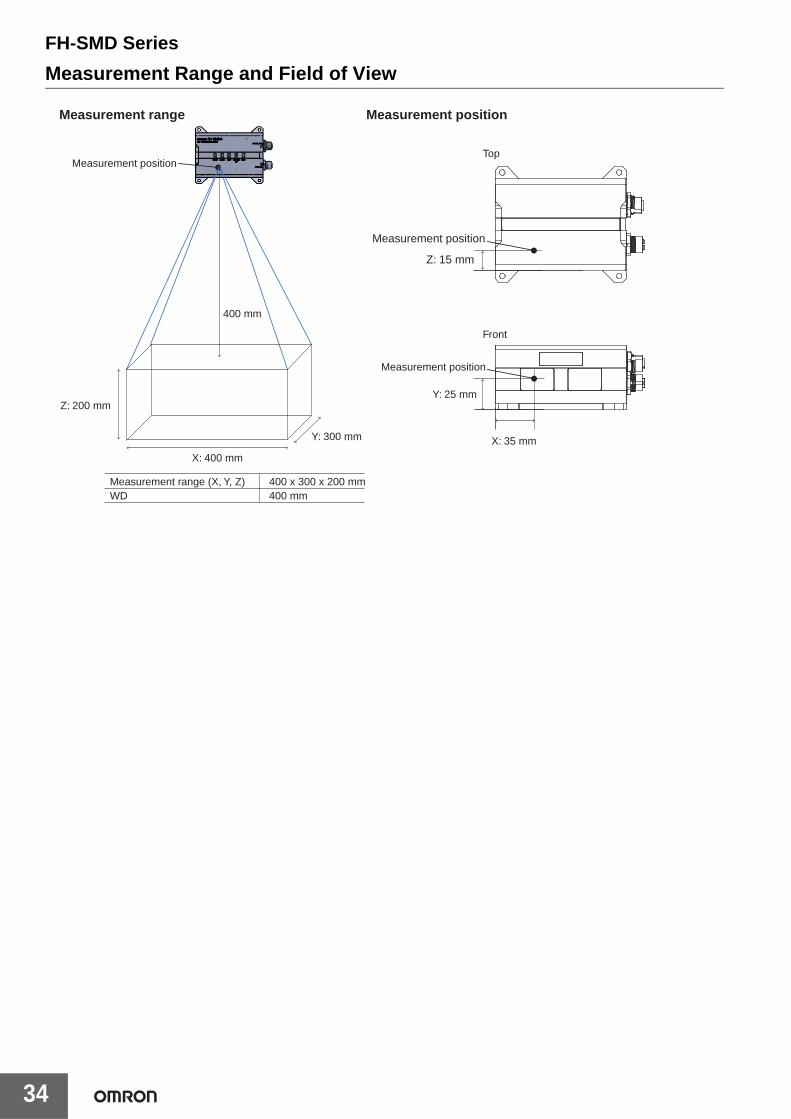
Measurement Range and Field of View
Y: 300 mm
Measurement position
400 mm
Z: 200 mm
X: 400 mm
Measurement range Measurement position
Top
Front
X: 35 mm
Measurement range (X, Y, Z)WD
400 x 300 x 200 mm400 mm
Measurement position
Measurement position
Y: 25 mm
Z: 15 mm

FH-SMD Series
35
Related ManualsMan.No. Model Manual
Z446 FH-5050/FH-SMDA-GS050B Vision System FH Series 3D Robot Vision Application Construction Guide
Z436 FH-5050/FH-SMDA-GS050B Vision System FH Series Hardware Setup Manual for 3D Robot Vision
Z445 FH-5050/FH-SMDA-GS050B Vision System FH/FHV7 Series Processing Item Function Reference Manual for 3D Robot Vision
Z365 FH-5050 Vision System FH/FHV7 Series User's Manual
Z341 FH-5050 Vision System FH/FHV7 Series Processing Item Function Reference Manual
Z367 FH-5050 Vision System FH Series Macro Customize Functions Programming Manual
Z342 FH-5050 FH/FHV7 Series User's Manual for Communications Settings
• EtherCAT® is a registered trademark and patented technology, licensed by Beckhoff Automation GmbH, Germany.• EtherNet/IPTM is a trademark of ODVA.• Microsoft® Visual Studio® and Windows are either registered trademarks or trademarks of Microsoft Corporation in the United States and/or
other countries.• QR code is the registered trademark of DENSO WAVE.• Intel and the Intel logo are trademarks of Intel Corporation in the U.S. and/or other countries.• The SD Logo is a trademark of SD-3C LLC.• Other company names and product names in this document are the trademarks or registered trademarks of their respective companies.• The product photographs and figures that are used in this catalog may vary somewhat from the actual products.• Microsoft product screen shot(s) used with permission from Microsoft Corporation.• The permission of Shutterstock.com was received for images that were used.

MEMO
36

Terms and Conditions AgreementRead and understand this catalog.
Please read and understand this catalog before purchasing the products. Please consult your OMRON representative if you have any questions or comments.
Warranties.(a) Exclusive Warranty. Omron’s exclusive warranty is that the Products will be free from defects in materials and workmanship
for a period of twelve months from the date of sale by Omron (or such other period expressed in writing by Omron). Omron disclaims all other warranties, express or implied.
(b) Limitations. OMRON MAKES NO WARRANTY OR REPRESENTATION, EXPRESS OR IMPLIED, ABOUT NON-INFRINGEMENT, MERCHANTABILITY OR FITNESS FOR A PARTICULAR PURPOSE OF THE PRODUCTS. BUYER ACKNOWLEDGES THAT IT ALONE HAS DETERMINED THAT THE PRODUCTS WILL SUITABLY MEET THE REQUIREMENTS OF THEIR INTENDED USE.
Omron further disclaims all warranties and responsibility of any type for claims or expenses based on infringement by the Products or otherwise of any intellectual property right. (c) Buyer Remedy. Omron’s sole obligation hereunder shall be, at Omron’s election, to (i) replace (in the form originally shipped with Buyer responsible for labor charges for removal or replacement thereof) the non-complying Product, (ii) repair the non-complying Product, or (iii) repay or credit Buyer an amount equal to the purchase price of the non-complying Product; provided that in no event shall Omron be responsible for warranty, repair, indemnity or any other claims or expenses regarding the Products unless Omron’s analysis confirms that the Products were properly handled, stored, installed and maintained and not subject to contamination, abuse, misuse or inappropriate modification. Return of any Products by Buyer must be approved in writing by Omron before shipment. Omron Companies shall not be liable for the suitability or unsuitability or the results from the use of Products in combination with any electrical or electronic components, circuits, system assemblies or any other materials or substances or environments. Any advice, recommendations or information given orally or in writing, are not to be construed as an amendment or addition to the above warranty.
See http://www.omron.com/global/ or contact your Omron representative for published information.
Limitation on Liability; Etc.OMRON COMPANIES SHALL NOT BE LIABLE FOR SPECIAL, INDIRECT, INCIDENTAL, OR CONSEQUENTIAL DAMAGES, LOSS OF PROFITS OR PRODUCTION OR COMMERCIAL LOSS IN ANY WAY CONNECTED WITH THE PRODUCTS, WHETHER SUCH CLAIM IS BASED IN CONTRACT, WARRANTY, NEGLIGENCE OR STRICT LIABILITY.
Further, in no event shall liability of Omron Companies exceed the individual price of the Product on which liability is asserted.
Suitability of Use.Omron Companies shall not be responsible for conformity with any standards, codes or regulations which apply to the combination of the Product in the Buyer’s application or use of the Product. At Buyer’s request, Omron will provide applicable third party certification documents identifying ratings and limitations of use which apply to the Product. This information by itself is not sufficient for a complete determination of the suitability of the Product in combination with the end product, machine, system, or other application or use. Buyer shall be solely responsible for determining appropriateness of the particular Product with respect to Buyer’s application, product or system. Buyer shall take application responsibility in all cases.
NEVER USE THE PRODUCT FOR AN APPLICATION INVOLVING SERIOUS RISK TO LIFE OR PROPERTY OR IN LARGE QUANTITIES WITHOUT ENSURING THAT THE SYSTEM AS A WHOLE HAS BEEN DESIGNED TO ADDRESS THE RISKS, AND THAT THE OMRON PRODUCT(S) IS PROPERLY RATED AND INSTALLED FOR THE INTENDED USE WITHIN THE OVERALL EQUIPMENT OR SYSTEM.
Programmable Products.Omron Companies shall not be responsible for the user’s programming of a programmable Product, or any consequence thereof.
Performance Data.Data presented in Omron Company websites, catalogs and other materials is provided as a guide for the user in determining suitability and does not constitute a warranty. It may represent the result of Omron’s test conditions, and the user must correlate it to actual application requirements. Actual performance is subject to the Omron’s Warranty and Limitations of Liability.
Change in Specifications.Product specifications and accessories may be changed at any time based on improvements and other reasons. It is our practice to change part numbers when published ratings or features are changed, or when significant construction changes are made. However, some specifications of the Product may be changed without any notice. When in doubt, special part numbers may be assigned to fix or establish key specifications for your application. Please consult with your Omron’s representative at any time to confirm actual specifications of purchased Product.
Errors and Omissions.Information presented by Omron Companies has been checked and is believed to be accurate; however, no responsibility is assumed for clerical, typographical or proofreading errors or omissions.

Note: Do not use this document to operate the Unit.