a compiler for hp vee - about hp labs | hp® official site 13 • 1998 hewlett packard company 98...
TRANSCRIPT
May 1998 • The Hewlett-Packard Journal98Article 13 • 1998 Hewlett Packard Company
A Compiler for HP VEE
With the addition of a compiler, HP VEE programs can now benefit from
improved execution speed and still provide the advantages of an interactive
interpreter.
This article presents the major algorithmic aspects of a compiler for the
Hewlett-Packard Visual Engineering Environment (HP VEE). HP VEE is a
powerful visual programming language that simplifies the development of
engineering test-and-measurement software. In the HP VEE development
environment, engineers design programs by linking visual objects (also called
devices) into block diagrams. Features provided in HP VEE include:
� Support for engineering math and graphics
� Instrument control
� Concurrency
� Data management
� GUI support
� Test sequencing
� Interactive development and debugging environment.
Beginning with release 4.0, HP VEE uses a compiler to improve the execution
speed of programs. The compiler translates an HP VEE program into byte-
code that is executed by an efficient interpreter embedded in HP VEE. By
analyzing the control structures and data type use of an HP VEE program, the
compiler determines the evaluation order of devices, eliminates unnecessary
run-time decisions, and uses appropriate data structures.
The HP VEE 4.0 compiler increases the performance of computation-intensive
programs by about 40 times over previous versions of HP VEE. In applications
where execution speed is constrained by instruments, file input and output, or
display update, performance typically increases by 150 to 400 percent.
������ � ������
������ ����� ���
������ � ������
A member of the technical
staff at HP Laboratories
since 1989, Steve Green-
baum is currently researching “hardware-in-
the-loop” systems and programming for distrib-
uted systems. He has a PhD degree in computer
science (1986) from the University of Illinois at
Urbana-Champaign and a BS degree in com-
puter science (1980) from Syracuse University.
Steve was born in New York City, is married,
and has two children. In his leisure time he
enjoys playing guitar and taking field trips with
his family.
������ ����� ���
Stanley Jefferson is a mem-
ber of the technical staff at
HP Laboratories, where he
began his career at HP in 1990. He is currently
doing research in the area of “hardware-in-the-
loop” systems. He has a PhD degree in com-
puter science (1988) from the University of
Illinois at Urbana-Champaign. He received BS
(1977) and MA (1979) degrees in mathematics
from the University of California at Davis. Stan
was born in Oakland, California, is married,
and has two children. He enjoys playing piano
and day trips to the beach with his family.
May 1998 • The Hewlett-Packard Journal99Article 13 • 1998 Hewlett Packard Company
The compiler described in this article is a prototype devel-oped by HP Laboratories to compile HP VEE 3.2 programs.The compiler in HP VEE 4.0 differs in some details.TheHP VEE prototype compiler consists of five components:
� Graph Transformation. Transformations are performedon a graph representation of the HP VEE program. Thetransformations facilitate future compilation phases.
� Device Scheduling. An execution ordering of devicesis obtained. The ordering may have hierarchical ele-ments, such as iterators, that are recursively ordered.The ordering preserves the data flow and control flowrelationships among devices in the HP VEE program.Scheduling does not, however, represent the run-timeflow branching behavior of special devices such asIf/Then/Else.
� Guard Assignment. The structure produced by schedul-ing is extended with constructs that represent run-timeflow branching. Each device is annotated with booleanguards that represent conditions that must be satisfiedat run time for the device to run. Adjacent devices withsimilar guards are grouped together to decrease redun-dancy of run-time guard processing. Guards can resultfrom explicit HP VEE branching constructs such asIf/Then/Else, or they can result from implicit propertiesof other devices, such as guards that indicate whetheran iterator has run at least once.
� Type Annotation. Devices are annotated with type infor-mation that gives a conservative analysis of what typesof data are input to, and output from, a device. The an-notations can be used to generate type-specific code.
� Code Generation. The data structures maintained by thecompiler are traversed to generate target code. The
prototype compiler can generate C code and byte-code.However, code generation is relatively straightforwardto implement for most target languages.
To simplify the presentation, many aspects of the HP VEElanguage and compiler are omitted or given cursory treat-ment. Notable in this regard is our cursory treatment ofconcurrency mechanisms (both the prototype compilerand the HP VEE 4.0 compiler handle concurrency). Onlya brief, somewhat formal description of the HP VEE lan-guage is presented. Less formal descriptions of HP VEEare given in the HP VEE manuals.1,2
Semantic Overview
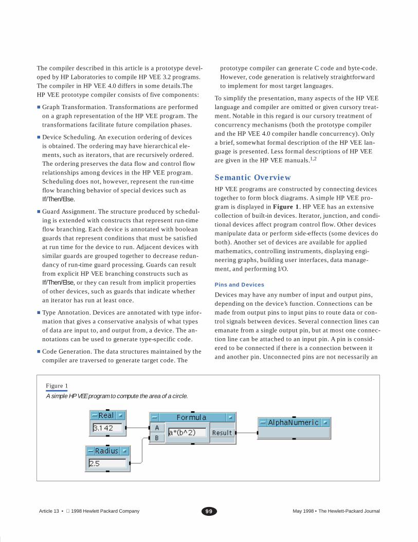
HP VEE programs are constructed by connecting devicestogether to form block diagrams. A simple HP VEE pro-gram is displayed in Figure 1. HP VEE has an extensivecollection of built-in devices. Iterator, junction, and condi-tional devices affect program control flow. Other devicesmanipulate data or perform side-effects (some devices doboth). Another set of devices are available for appliedmathematics, controlling instruments, displaying engi-neering graphs, building user interfaces, data manage-ment, and performing I/O.
Pins and Devices
Devices may have any number of input and output pins,depending on the device’s function. Connections can bemade from output pins to input pins to route data or con-trol signals between devices. Several connection lines canemanate from a single output pin, but at most one connec-tion line can be attached to an input pin. A pin is consid-ered to be connected if there is a connection between itand another pin. Unconnected pins are not necessarily an
Figure 1
A simple HP VEE program to compute the area of a circle.

May 1998 • The Hewlett-Packard Journal100Article 13 • 1998 Hewlett Packard Company
error condition, but they serve no useful purpose. It willsimplify discussions to assume that they are not present.Thus, the statement “data is placed on all output pins”implicitly excludes all unconnected output pins.
When a device executes, it performs a computation basedon the values present on its input pins (if any) and pro-duces results that are placed on appropriate output pins(if any). The value placed on an output pin is also propa-gated to any input pins that are connected to it. The com-bination of placing a value on an output pin and propagat-ing the value is called “firing the output pin.” Only onevalue can be present on a pin, so previous values are over-written by new values. Unlike traditional data-flow modelswhere input values are consumed, in HP VEE values ondata input pins remain available for further use after theyare used as input by an executing device.
There are five kinds of pins that may be attached to adevice:
� Data pins provide the input/output interface to a de-vice. The data input pins attach to the left edge of adevice and the data output pins attach to the right edgeof a device. Most devices will not operate until data ispresent at all data input pins. After a device operates,data is placed on the output data pins.
� Sequence pins are an option that allow greater controlover the order in which devices operate. Most deviceshave sequence input and sequence output pins. Thesequence input pin is attached to the middle of the topedge of a device and the sequence output pin is attachedto the middle of the bottom edge of a device. All of thedevices in Figure 1 have unconnected sequence pins.Either sequence pin may be left unconnected. If the se-quence input of a device is connected, then the devicewill not operate until the data input pins and sequenceinput pin have data. Sequence output pins are explainedlater.
� Execute pins are special input pins that force the deviceto operate and place results on its output pins. Executepins are usually referred to as XEQ pins. XEQ pins operateregardless of the presence of other inputs.
� Control pins are special inputs that affect the internalstate of a device, but have no effect on the propagationof data values through the device. Common control pinsare Clear and Reset. Control pins operate regardless ofthe presence of other inputs.
� Error pins are optional output pins. The presence of anerror pin causes any errors generated by the attacheddevice to be trapped. The appropriate error code isoutput on the error pin.
A device can also have individual properties that are spe-cified at development time. For example, the buffer sizeand grid type can be specified for a strip chart displaydevice.
Data Types
The data types in HP VEE are integer, real, complex, polarcomplex, waveform, spectrum, coordinate, enum, text, andrecord. Multidimensional arrays can be built from thesedata types. Generally, the input and output pins on adevice are not typed, and connections are never typed.Rather, the data objects themselves are typed. Most of thedevices in HP VEE will accept any type of data, and theyautomatically perform any necessary type conversions.For example, the addition device will accept any combi-nation of integer, real, complex, or array arguments.Appropriate types are output based on the input types.Some devices require particular data types as input andwill either perform a conversion or signal an error whenpresented with a data object not meeting the type require-ment. Most devices allow a user-specified type conversionto be associated with each input pin. In addition, mostdevices allow the user to require that the data be acertain shape (scalar, array, one-dimensional array, two-dimensional array, etc.). There is a nil value that is a valueof every type and means “no information.” The absence ofa value at a pin is different from the presence of a nil value.
Terminology
A connection is a set (unordered) consisting of an inputpin and an output pin. Devices x and y are connected ifthere is a connection c such that one of the pins in c isattached to device x and the other pin in c is attached todevice y. Unless otherwise specified, connections be-tween devices are undirected. Hence, a connection be-tween devices x and y is also a connection between de-vices y and x. If x1,...,xn is a sequence of devices andc1,...,cn�1 is a sequence of connections such that ci is aconnection between xi and xi�1 for i�1,...,n�1, we saythat c1,...,cn�1 is an (undirected) path from x1 to xn. Forexample, in Figure 1 there is a path from the Radius de-vice to the Real device. A diagram is pathwise connected
if there is at least one path between every pair of devices

May 1998 • The Hewlett-Packard Journal101Article 13 • 1998 Hewlett Packard Company
in the diagram. A device x is a direct ancestor of a devicey if there is a connection from an output pin of x to aninput pin of y. In this case, we also say that y is a direct
descendant of x. A device u is an ancestor of a device v ifthere is a sequence of devices w1,...,wn with u�w1 andv�wn such that wi is a direct ancestor of wi�1 fori�1,...,n�1. Also, if ci is a connection from an output pinof wi to an input pin of wi�1, then the sequence c1,...,cn�1
is called a directed path from u to v. If u is an ancestor ofv, we may also say v is a descendant of u. A cycle or feed-
back loop is a directed path from a device to itself. A pin poccurs in a cycle c1,...,cm if p is a member of some ci. Thedescendants of a device u are all the devices v for whicha directed path exists from u to v. In a diagram with acycle, it is possible for a device to be a member of itsdescendants.
Data Flow
An HP VEE program is run by executing the devices in theprogram. The order in which the devices execute is con-strained by the connections between the devices andsome built-in priority rules. We say that a device’s data
dependencies are satisfied if all of its connected datainput pins and its sequence input pin (if connected) havedata present. The basic rule governing the executionorder of devices is that a device can execute only whenits data dependencies are satisfied. We call this the data
dependency rule.
A device that is neither an iterator, junction, nor asynchro-nous* device is called a primitive device. The executionorder of primitive devices in a connected diagram wherethe only connections are between data output pins anddata input or sequence input pins is governed by the datadependency rule. A diagram of this form is run by allowingeach device to execute at most once, subject to the order-ing constraint imposed by the data dependency rule. Oneway to run such a diagram is to repeatedly choose an un-executed device whose data dependencies are satisfiedand execute it until there are no devices left to choose.Each time a device executes, the values propagated fromits outputs may satisfy the data dependencies of descen-dant devices, thus making additional devices available forexecution. The process of running a diagram (or subdia-gram) D is referred to as a sweep over D. The program inFigure 1 can execute its devices in the order Radius, Real,
* Asynchronous devices, such as Delay and Confirm, are not treated in this paper.
Figure 2
A diagram with two independent threads.
Formula, Alphanumeric or in the order Real, Radius, Formula,Alphanumeric.
A maximal pathwise connected subdiagram of a diagramD is called an independent thread of D (connections tocontrol pins are ignored when determining independentthreads in HP VEE). For example, the diagram in Figure 2
has two independent threads. Suppose that D is an HPVEE program consisting of n independent threads. Then asweep over D initiates a subsweep over each of the n in-dependent threads. Each subsweep executes indepen-dently of the others and the n subsweeps all run concur-rently (or in a time-sliced manner). The sweep over D iscompleted when all n subsweeps are completed.
Later, we will present control constructs that initiate sub-sweeps over subdiagrams. In general, it is possible to havearbitrarily nested subsweeps during the execution of aprogram. Let s1,...,sn be a sequence of sweeps such thatsi�1 is a subsweep of si for i�1,...,n�1. Then, the se-quence s1,...,sn is called a nested sequence of sweeps, andwe say that si is a supersweep of sj whenever i�j. Ifs1,...,sn is a nested sequence of sweeps and we are cur-rently executing the sweep sn, then s1,...,sn are said to beactive, but only sn is said to be executing.
The following execution nesting rule is a generalizationof the rule that devices execute at most once per sweep.Let s1,...,sn be a nested sequence of sweeps and d be anydevice except a junction device. If d is directly executedby the innermost subsweep sn, then device d can not bedirectly executed again by any of the si, for i�n, but itmay be directly executed again by a newly created sub-sweep of an si for i�n.
We glossed over a technical detail regarding device execu-tion. Consider a device that has a data input pin, an XEQ
May 1998 • The Hewlett-Packard Journal102Article 13 • 1998 Hewlett Packard Company
pin, and a control pin. Each of these pins correspondsto a different action. Which actions qualify as executingthe device? The detailed answer is given in the section“Execute and Control Pin Splitting” on page 107. Theshort answer in this particular case is that the device isviewed as three devices where each device correspondsto a different input pin, and each of the three devices canexecute subject to the execution nesting rule.
Sequence Pins
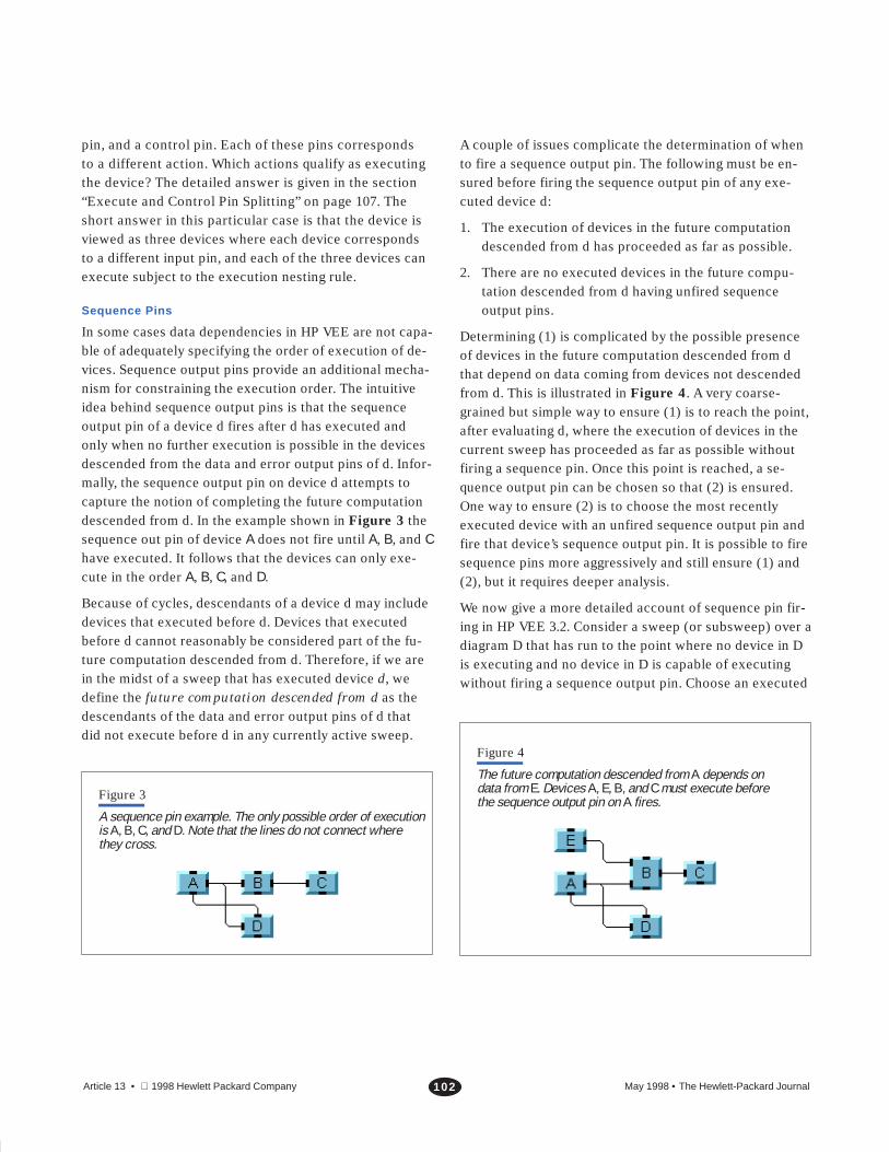
In some cases data dependencies in HP VEE are not capa-ble of adequately specifying the order of execution of de-vices. Sequence output pins provide an additional mecha-nism for constraining the execution order. The intuitiveidea behind sequence output pins is that the sequenceoutput pin of a device d fires after d has executed andonly when no further execution is possible in the devicesdescended from the data and error output pins of d. Infor-mally, the sequence output pin on device d attempts tocapture the notion of completing the future computationdescended from d. In the example shown in Figure 3 thesequence out pin of device A does not fire until A, B, and Chave executed. It follows that the devices can only exe-cute in the order A, B, C, and D.
Because of cycles, descendants of a device d may includedevices that executed before d. Devices that executedbefore d cannot reasonably be considered part of the fu-ture computation descended from d. Therefore, if we arein the midst of a sweep that has executed device d, wedefine the future computation descended from d as thedescendants of the data and error output pins of d thatdid not execute before d in any currently active sweep.
Figure 3
A sequence pin example. The only possible order of executionis A, B, C, and D. Note that the lines do not connect wherethey cross.
A couple of issues complicate the determination of whento fire a sequence output pin. The following must be en-sured before firing the sequence output pin of any exe-cuted device d:
1. The execution of devices in the future computationdescended from d has proceeded as far as possible.
2. There are no executed devices in the future compu-tation descended from d having unfired sequenceoutput pins.
Determining (1) is complicated by the possible presenceof devices in the future computation descended from dthat depend on data coming from devices not descendedfrom d. This is illustrated in Figure 4. A very coarse-grained but simple way to ensure (1) is to reach the point,after evaluating d, where the execution of devices in thecurrent sweep has proceeded as far as possible withoutfiring a sequence pin. Once this point is reached, a se-quence output pin can be chosen so that (2) is ensured.One way to ensure (2) is to choose the most recentlyexecuted device with an unfired sequence output pin andfire that device’s sequence output pin. It is possible to firesequence pins more aggressively and still ensure (1) and(2), but it requires deeper analysis.
We now give a more detailed account of sequence pin fir-ing in HP VEE 3.2. Consider a sweep (or subsweep) over adiagram D that has run to the point where no device in Dis executing and no device in D is capable of executingwithout firing a sequence output pin. Choose an executed
Figure 4
The future computation descended from A depends ondata from E. Devices A, E, B, and C must execute beforethe sequence output pin on A fires.

May 1998 • The Hewlett-Packard Journal103Article 13 • 1998 Hewlett Packard Company
device d in D such that d is the most recently executeddevice having an unfired sequence output pin (if there arenone then the sweep is finished). Propagate a nil valuefrom the sequence output pin of d, and continue the sweepof D until no unexecuted devices with satisfied data de-pendencies are available. Repeat this process of firingsequence output pins until all sequence output pins onexecuted devices in D have been fired. When further repe-titions are not possible, the sweep over D is completed.
Note that sequence output pins in different subsweeps arehandled independently. Sequence output pins are fired aspart of the subsweep that executed their attached device,and the order of their firing depends only on the devicesand sequence output pins in that subsweep.
If/Then/Else
The If/Then/Else device is used for branching the data flow,and hence the execution flow. The programmer specifiesany number of named data input pins and a list of expres-sions over those pins. Each expression corresponds to adifferent data output pin. When the If/Then/Else deviceexecutes, the expressions are evaluated in order until thefirst expression that evaluates to a True (nonzero) value isfound. At this point, expression evaluation ceases, and thevalue is output on the data output pin corresponding to thetrue expression. If no expression evaluates to True, thenzero is output on the default Else data output pin. Notethat only one data output pin of the If/Then/Else deviceoutputs a value. Thus, the other data output pins will notpropagate a value, and hence none of their descendantswill be able to execute (because of the data dependencyrule).
Iterators
One consequence of the execution nesting rule is thatfeedback loops in HP VEE can never result in iteration.Instead, HP VEE has iterator devices that explicitly per-form iteration. These iterator devices repeatedly run thesubdiagram descended from their output pin. It should benoted that iterator devices do not impose any hierarchicalstructure on the displayed HP VEE program, but are sim-ply displayed as an ordinary device. The ForCount iteratoris shown in Figure 5. The ForCount device outputs thesequence 0, 1, 2,...,n�1, where n is an iteration count thatcan be input at runtime or set at development time. Whenthe ForCount is run during a sweep, it outputs a zero(assuming the iteration count is greater than zero) andstarts a subsweep on the diagram descended from itsoutput pin. When the subsweep is finished, the ForCountdetermines whether it has output its last value. If not, theForCount outputs its next value and performs another sub-sweep. This process of performing subsweeps continuesuntil the final value of the ForCount is output, at which timethe ForCount ends its execution. Note that the ForCount isin an outer sweep relative to the subsweeps on its descen-dants, and that it is executed only once during the sweepthat initiated its execution (one can think of the ForCountas being in a paused state when its subsweeps run).
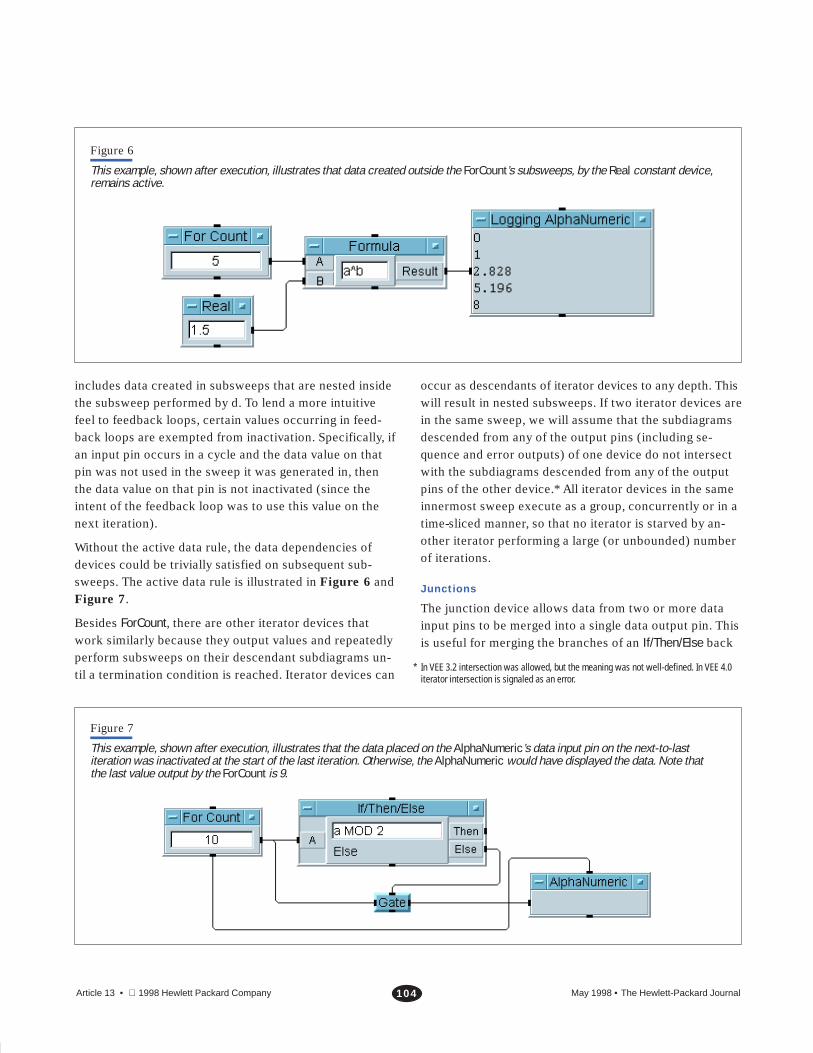
The following active data rule applies to devices such asiterators, junctions, and UserObjects that can create a newsubsweep. Let d be a device that creates a new subsweep.Immediately before each subsweep created by d, all datacreated in the previous subsweep (if there was one) per-formed by d is inactivated (that is, made unusable). This
Figure 5
An example using ForCount. The result of running the program is shown. The Formula and Logging AlphaNumeric deviceshave been iterated five times.
May 1998 • The Hewlett-Packard Journal104Article 13 • 1998 Hewlett Packard Company
Figure 6
This example, shown after execution, illustrates that data created outside the ForCount’s subsweeps, by the Real constant device,remains active.
includes data created in subsweeps that are nested insidethe subsweep performed by d. To lend a more intuitivefeel to feedback loops, certain values occurring in feed-back loops are exempted from inactivation. Specifically, ifan input pin occurs in a cycle and the data value on thatpin was not used in the sweep it was generated in, thenthe data value on that pin is not inactivated (since theintent of the feedback loop was to use this value on thenext iteration).
Without the active data rule, the data dependencies ofdevices could be trivially satisfied on subsequent sub-sweeps. The active data rule is illustrated in Figure 6 andFigure 7.
Besides ForCount, there are other iterator devices thatwork similarly because they output values and repeatedlyperform subsweeps on their descendant subdiagrams un-til a termination condition is reached. Iterator devices can
occur as descendants of iterator devices to any depth. Thiswill result in nested subsweeps. If two iterator devices arein the same sweep, we will assume that the subdiagramsdescended from any of the output pins (including se-quence and error outputs) of one device do not intersectwith the subdiagrams descended from any of the outputpins of the other device.* All iterator devices in the sameinnermost sweep execute as a group, concurrently or in atime-sliced manner, so that no iterator is starved by an-other iterator performing a large (or unbounded) numberof iterations.
Junctions
The junction device allows data from two or more datainput pins to be merged into a single data output pin. Thisis useful for merging the branches of an If/Then/Else back
* In VEE 3.2 intersection was allowed, but the meaning was not well-defined. In VEE 4.0iterator intersection is signaled as an error.
Figure 7
This example, shown after execution, illustrates that the data placed on the AlphaNumeric’s data input pin on the next-to-lastiteration was inactivated at the start of the last iteration. Otherwise, the AlphaNumeric would have displayed the data. Note thatthe last value output by the ForCount is 9.

May 1998 • The Hewlett-Packard Journal105Article 13 • 1998 Hewlett Packard Company
Figure 8
An example of a junction merging the branches of an If/Then/Else. When run, this program displays the absolute value of its input.In this case, the AlphaNumeric would display 4 when the program is run.
together, for initializing feedback loops, or for iteratingthe inputs of the junction. See Figure 8 and Figure 9 forexamples. In the If/Then/Else merge and feedback initial-ization cases, at most one of the junction device’s datainput pins will receive a value during a sweep. Thus, thejunction device does not have to satisfy the data depen-dency rule to execute. The junction device can executewhenever one or more data input pins has a value. If ajunction, j, initiates a sweep s of its descendants, thenneither s nor any subsweep nested inside s may execute j.This restriction prevents iteration resulting from feedback.Unlike other devices, the junction device consumes itsdata input values when it executes. When the junctiondevice executes, it repeatedly sweeps over the descen-dants of its data output pin just like an iterator, using the
Figure 9
This example, shown after execution, illustrates a junctionbeing used to initialize a feedback loop.
data input values as data output values. Thus, subsweepsperformed by a junction are subject to the active datarule. Although a junction performs subsweeps in the samemanner as an iterator, it is not an iterator. The prototypecompiler assumes that junctions that are in the samesweep execute in an arbitrary serial order rather thanconcurrently, and the descendants of different junctionsin the same sweep are allowed to intersect.
User Objects
Subprograms can be written in HP VEE using the User-Object device. The UserObject provides a subwindow inwhich a block diagram can be constructed. A UserObject isshown in Figure 10. The data input pins of a UserObjecthave corresponding terminals inside the UserObject’s sub-window. The diagram contained in the UserObject can con-nect to these terminals in order to obtain the data on theUserObject’s data input pins. The data output pins of aUserObject are handled similarly. UserObjects operate underthe same rules as any primitive device. All data inputsmust be present before the UserObject executes. When theUserObject executes, its diagram is executed as if it werea top-level diagram. The sweep over the UserObject’sdiagram runs further subsweeps over the independentthreads of the diagram. When the sweep of the User-Object’s diagram is finished, the last values placed on theterminals of the UserObject’s data output pins are trans-ferred to their corresponding data output pins, and theUserObject completes its execution. UserObjects may alsohave error and sequence pin connections.

May 1998 • The Hewlett-Packard Journal106Article 13 • 1998 Hewlett Packard Company
Figure 10
A UserObject that determines the sign of its input.
Phases of a Sweep
During a sweep s over a diagram D, a priority orderingaffects the order of device executions and sequence out-put pin firings in D. If a subsweep of s is initiated, then itspriority ordering will begin fresh and will be independentof the ordering in sweep s. The following summarizes thepriority classes of a sweep from high to low priority.
1. If there are primitive devices whose data dependen-cies are satisfied, then one is chosen and executed.This process is continued until there are no primitivedevices whose dependencies are satisfied. Note thatadditional primitive devices may have their data de-pendencies satisfied as data is propagated from theoutput pins of executed devices, and thus they willbecome eligible for execution during this priorityphase.
2. All junction devices that have data present on at leastone input pin are executed. The junctions are executedin an arbitrary serial order, and each one initiates anew subsweep.
3. All iterator devices that have their data dependenciessatisfied are executed. The iterator devices are exe-cuted concurrently and each one initiates a new sub-sweep.
4. If a sequence output pin is eligible to fire, it is fired asdescribed earlier, and then the current sweep contin-ues at step 1. If there are no sequence output pinseligible to fire, the current sweep is over.
Example
Consider the execution of the program in Figure 9. Thezero constant device executes first as it is the only primi-tive device with its data dependencies satisfied. Then thejunction device executes, outputting the data that is on itsupper data input pin. At this point there are no primitivesor junctions that can execute, so we execute the ForCount.The ForCount outputs a zero and starts a subsweep over itsdescendants. The subsweep begins with the highest prior-ity devices. The addition device is a primitive device andnow has its data dependencies satisfied, so it executes.The data output by the addition device satisfies the datadependencies of the display device and the junction.Since the display device is primitive it has priority overthe junction, so it executes, displaying a zero. There arenow no primitive devices left in the subsweep that canexecute, so the junction executes. The junction outputsthe data that is on its bottom input pin and starts a sub-sweep. The junction’s subsweep immediately terminatessince all of the descendants of the junction are prohibitedfrom executing because of the execution nesting rule. Nomore devices can execute in the subsweep started by theForCount since all of the devices descended from the For-Count have executed once in this current subsweep. Thus,the current subsweep ends and the ForCount readies foranother iteration. Before performing the next iteration,the active data rule is applied, inactivating all of the datacreated on the previous sweep except the data that wasoutput by the junction, since it is exempt because of

May 1998 • The Hewlett-Packard Journal107Article 13 • 1998 Hewlett Packard Company
feedback. The ForCount outputs a one and performsanother sweep. The descendants of the ForCount are alleligible to run since we have backed out of the subsweepin which they were previously run. Thus, this second sub-sweep proceeds in the same manner as the previous sub-sweep. Iterations continue in this way until the ForCounthas performed five iterations, at which point the top-levelsweep is terminated. Note that feedback is simply a mech-anism for using values generated in previous sweeps.
Architecture of the Compiler
Block Diagram Representation
The internal representation of an HP VEE program is adirected graph constructed of objects that represent de-vices, with edges between these objects corresponding tothe connections visible in the pictorial view. Informationabout the pictorial presentation is maintained within theinternal device graph, but the compiler is only concernedwith the connection structure of an HP VEE program.
Transformations
Before the main compilation analysis takes place, thecompiler may modify the internal device graph to simplifyanalysis. These modifications replace constructs havingspecial behaviors by collections of simpler constructs thatall have standard behaviors. Such graph modificationsonly affect the internal representation, and are invisible tothe user.
Execute and Control Pin Splitting. For purposes of com-pilation it is convenient to assume that all nonjunction HPVEE devices fire only after all their inputs receive data.However, some HP VEE devices may activate when only asubset of their inputs have data, typically because suchdevices have some execute or control pins (described inthe section “Pins and Devices” on page 99). To avoid hav-ing to consider the types of input pins when performinglater stages of compilation, devices with such pins aresplit into multiple “synthetic” devices such that each syn-thetic device fires after all its inputs receive data. Syntheticdevices are device types that only exist when created bythe compiler. They are not part of the user-level HP VEEdevices and they never appear on the display.
For example, consider a Sample&Hold device. A Sample&Hold has a data input pin and an execute pin. Data enteringon the data pin is copied to a buffer in the Sample&Hold
device, but the data is not propagated to the output pinuntil the execute pin is fired (that is, receives data).Figure 11 shows how a Sample&Hold device is split intotwo synthetic devices: SH-Set and SH-Xeq.
The semantic role of SH-Set is to store the data from thedata input of Sample&Hold into the buffer associated withSample&Hold, and SH-Xeq’s job is to put the data in thebuffer onto the output pin. Links are made between thesedevices so the compiler can find either one from the other.The semantic behavior of this collection of synthetic de-vices, as so connected, is equivalent to the original singledevice in its context. The HP VEE user interface has thesingle Sample&Hold device instead of the two separatedevices because the tight functional coupling of the twobehaviors makes it easier to conceptualize the compositefunctionality as the action of a single device, making HP
Figure 11
Expansion of execute pins.
Is Converted to
and

May 1998 • The Hewlett-Packard Journal108Article 13 • 1998 Hewlett Packard Company
VEE easier to use. The compiler does the conversion tosimplify compilation.
Like execute pins, control pins also lead to device split-ting, but they have a simpler reconnection scheme. Con-trol pins affect the state of a device, but they are not di-rectly involved in determining when a device can fire.They only cause side effects within the device. If a devicehas N control pins, it is split into N�1 synthetic devicessuch that one synthetic device is similar to the originaldevice but with the control pins removed. Each of theother N synthetic devices is associated with one controlpin by having the synthetic device’s single “normal” datainput get the input that had gone to the associated controlpin. See Figure 12 for an example (lines attached to con-trol inputs are drawn with dashed lines in HP VEE). Thesesynthetic control pin devices implement the side effect thatthe associated control pin was meant to perform. Links aremade between the synthetic and original devices to facili-tate generating code.
There is a subtlety about control pin semantics that is notaddressed merely by splitting. The semantics of controlpins dictate that the action they implement take placemore or less at the time the pin receives data. Thus if asynthetic device implementing a control pin action hasreceived data, it should be scheduled to execute as soonas possible, ahead of other devices that may also be readyto run. To implement this behavior, control pin devicesare tagged as high-priority devices, which cause thescheduler to schedule them for execution before normal-priority devices. This is a general mechanism that can beused for other devices that need to be run at high priority.
A device with both control and execute pins can be ex-panded by combining expansion techniques in a straight-forward way.
Synthesized Constructs. It is sometimes beneficial tosplit devices that do not have execute or control pins.This is useful for devices having complex semantics thatcan be implemented with combinations of simpler de-vices. This can be thought of as using the device level ofHP VEE to implement parts of the compiler. It can also beviewed as macro expansion.
The compiler uses this idea to implement the OnCycledevice. An OnCycle is split into two synthetic devices andone standard RepeatUntilBreak iterator. The idea is thatOnCycle is like a RepeatUntilBreak iterator except it only
Figure 12
Expansion of control pins.
Is Converted to
and
and
fires at certain time intervals. This is implemented by ini-tializing a time variable in a synthetic initialization device,then running a RepeatUntilBreak iterator whose outputgoes into a synthetic device that waits until the propertime, then that waiting device connects to what the On-Cycle connected to (see Figure 13).

May 1998 • The Hewlett-Packard Journal109Article 13 • 1998 Hewlett Packard Company
Figure 13
Expansion of an OnCycle device.
Expands into
Scheduling
The scheduler is the part of the HP VEE compiler that de-termines the order of execution of devices in an HP VEEprogram. From the HP VEE device graph, it produces aschedule, which is a tree representation of a fairly con-ventional control-flow program (such as what might cor-respond to a C program).
Although in general the scheduler determines the programstructure, it does not attempt to express the run-timepath-branching aspects of special HP VEE constructs. Forexample, the scheduler treats the If/Then/Else device as anormal primitive device, and therefore assumes all itsoutput pins will fire each time it is executed, although itactually only fires a single pin. The scheduler does thisbecause If/Then/Else can be used in ways that do not di-rectly map into a typical program structure. A later passof the compiler, called guarding, extends the schedule byadding constructs that represent the flow branchingwhich was ignored by the scheduler. Guarding also takescare of some other situations in which run-time decisionsmust be made. Guarding is described on page 113.
The basic method used by the scheduler is to traversethe device graph in proper execution order, producing astructure that represents the order and program structurediscovered during the traversal. The traversal does notevaluate the program, but only considers basic aspects ofthe device types. For example, iterators are not traversedmultiple times, but the descendants that would be repeat-edly executed at run time are determined.
When the scheduler encounters a device, the device iscategorized as being in one of four categories, dependingon its type. Other than this categorization, the type of thedevice is ignored by the scheduler. The device categoriesare: iterators, junctions, asynchronous devices (for exam-ple, Delay and Confirm), and everything else. Devices in thelast category are referred to as primitive devices. Compila-tion details for asynchronous devices are not included inthis paper. Although the HP VEE language does not havepure data flow semantics, data flow is used as a basicsemantic building block. Simple data flow graphs can beserialized using topological sort, often called topsort,which is a well known, efficient algorithm.3 The scheduleris based on topsort, but has significant modifications.

May 1998 • The Hewlett-Packard Journal110Article 13 • 1998 Hewlett Packard Company
Figure 14
Topsort.
Topsort (Graph) { Ready–Nodes <– nodes in Graph that have all their input pins fired if (Ready–Nodes is Empty) return Empty else Fire outputs of all nodes in Ready–Nodes return append(Ready–Nodes, Topsort(Graph – Ready–Nodes))}
Note: A node with no inputs is ”ready.”
Topsort takes a directed graph as argument and returns alist of nodes. Each node in the returned list satisfies thecriterion that its ancestors occur before it in the returnedlist. All nodes from the graph that can satisfy this criterionare included. Only nodes that are part of cycles in thegraph cannot be topologically sorted. If there is more thanone topological sort for a graph, any one is a valid result.See Figure 14 for a sketch of the topsort algorithm. Herean input is considered to be fired if the output it is directlyconnected to has been fired. Nodes with no inputs areconsidered to have all their input pins fired.
For a simple data flow graph, the ancestor/descendantrelationship is one of data dependency. The topsort ofsuch a graph lists devices in an order such that a deviceappears in the list after all the devices that produce datafor it. Therefore, in these cases topsort can be used as adevice-ordering compilation mechanism, eliminating theneed for run-time calculation of what to evaluate next.
Priority Ordering. An HP VEE program that contains onlyprimitive devices and does not use sequence output pinscan be scheduled using topsort. However, adding otherclasses of devices or sequence output pins complicatesmatters. For this discussion we will consider an HP VEEprogram to consist of primitive devices, junctions, anditerators. UserObjects will be classified as standard primi-tive devices. We will temporarily ignore sequence outpins.
The section “Phases of a Sweep” (page 106) describeddevice classes and their prioritized execution order. Thescheduler reflects this class-based ordering by extendingtopsort to keep separate lists of ready devices accordingto device class, and scheduling items from each class atthe proper time.
The structure of the HP VEE program being compiled isreflected in the resulting schedule by having a subsche-dule computed as a result of the simulated execution of acontrol (sweep-inducing) device, and storing that sub-schedule as the body of the device. For example, the bodyof an iterator is that part of the schedule that results fromfiring the data output pin of the iterator. This results in ahierarchical schedule consisting of a list of devices, withsome devices in the list having a subschedule stored astheir body. Subschedules are lists of devices, some ofwhich may have their own subschedules.
HP VEE maintains a list of all UserObjects, and their dia-grams are compiled one by one at the top level. Whenthey are encountered as a device during scheduling, theyare treated like noncompound devices; their contents arenot recursively compiled.
The diagram and environment corresponding to the mainprogram or a UserObject subprogram is called a context.Internally, a context is represented by a synthetic contextdevice whose substructure includes a list of independentthreads (described in the section “Data Flow,” onpage 101). Each independent thread is a directed graph.
When a context is run, the independent threads run inde-pendently and concurrently. The scheduler represents thisparallel execution using a Fork abstract syntax constructor,which is also used for parallel iterators and other concur-rency. The Fork has a list of threads that run in parallelwith each other such that the construct represented byFork is considered executing while any of its threads areexecuting. Figure 15 shows a listing of the schedulerprogram as described so far.

May 1998 • The Hewlett-Packard Journal111Article 13 • 1998 Hewlett Packard Company
Schedule–Context (Context) { for each independent–thread in Independent–Threads (Context) // Initialize P, J, and I Devices–With–No–Inputs(Independent–thread, &P, &J, &I) body(independent–thread) <– Schedule(P, J, I)
// The body of a Context is a Fork of its independent threads. body(Context) <– Make–Fork(Independent–Threads(Context))}
Schedule (P, J, I) { if (P not Empty) d <– pop(P) // Removes first element from P Fire–Data–Out–Pins(d, &P, &J, &I) // May add to P, J, and I. return push(d, Schedule(P, J, I)) else if (J not Empty) for each j in J Fire–Data–Out–Pins(j, &jP, &jJ, &jI) body (j) <– Schedule (jP, jJ, jI) return append(J, Schedule(Empty, Empty, I)) else if (I not Empty) for each i in I Fire–Data–Out–Pins(i, &iP, &iJ, &iI) body(i) <– Schedule(iP, iJ, iI) return push(Make–Fork(I), Schedule(Empty, Empty, Empty)) else return Empty}
Fire–Data–Out–Pins (D, *P &J, *I) { For each data output pin, O utPin , of device D, call Fire–Pin( Outpin , &P, &J, &I). Return value is not specified.}
Fire–Pin (OutPin, *P, *J, *I) { Fire output pin OutPin. For each input pin IP that OutPin is directly connected to, mark IP as ”fired” (i.e., as having active data). If IP is attached to device D, and firing IP causes D to have its data dependencies satisfied, then add D to (the de–reference of) one of P, J, or I, which are pointers to variables holding primitive devices, junctions, and iterators, respectively. Return value is not specified.}
Make–Fork (Threads) { Takes a list of ”threads,” where each thread is a list, and returns an object representing a Fork construct where all the threads run concurrently with each other. If the list of threads is empty, the resulting Fork represents an operation that does nothing and returns immediately.}
Note: &variable denotes the address of variable, as in C. Within aformal parameter list, * variable indicates that variable is passed by reference, analogous to C.
Figure 15
Basic scheduling.

May 1998 • The Hewlett-Packard Journal112Article 13 • 1998 Hewlett Packard Company
The lists P, J, and I in the scheduler of Figure 15 are listsof devices with satisfied data dependencies that are wait-ing to be scheduled. These lists hold primitive devices,junctions, and iterators, respectively.
The routine Fire-Pin adds devices to these lists as the de-vices become ready. When adding a device, Fire-Pin couldplace the device at the beginning, end, or somewhere elsein a list. Placing devices at the beginning leads to a moredepth-first traversal, while placing devices at the end ismore breadth-first. The semantics of HP VEE do not con-strain this aspect of the ordering. The scheduler uses thedepth-first option because that ordering can lead to im-proved efficiency of guard evaluation at run time (see“Guarding Phase Passes” on page 113).
Care must be used when Fire-Pin places junctions on theirready list. Junctions are the only devices the schedulersees that have their data dependencies satisfied by anysubset of their input pins (other cases are removed asdescribed in “Tranformations” on page 107). Thus, whenany input pin of a junction is fired, it can be placed on its
ready list. However, if a junction pin fires while the junc-tion is currently in the ready list, the junction should notbe placed on the list again. This is easy to accomplish bymaintaining an ignore marker in a junction that is setwhen the junction is placed on the ready list and clearedafter a junction is scheduled. Depending on how junctionsare compiled, it may be necessary to record which pinsare fired, even when the junction has its ignore marker set.
Sequence Out Pins. HP VEE 3.2 takes a conservative ap-proach by not firing sequence output pins until after exe-cuting all devices that can execute without firing a se-quence output pin directly in the current sweep (but theycan fire in subsweeps). Then a sequence output pin isfired (see “Sequence Pins” on page 102 for more aboutsequence output pins). A listing of the extended Scheduleroutine to implement sequence output pins is shown inFigure 16.
Figure 16
Implementation of sequence out pins.
Schedule (P, J, I, S) { if (P not Empty) d <– pop(P) // Removes first element from P. if (has–sequence–out–pin(d)) S <– push(seq–out–pin(d), S) // Add to top of S. Fire–Data–Out–Pins(d, &P, &J, &I) // May add to P, J, and I. return push(d, Schedule(P, J, I, S)) else if (J not Empty) for each j in J Fire–Data–Out–Pins(j, &jP, &jJ, &jI) body(j) <– Schedule(jP, jJ, jI, Empty) else if (I not Empty) for each i in I if (has–sequence–out–pin(i)) S <– push(seq–out–pin(i), S) // Add to top of S. Fire–Data–Out–Pins(i, &iP, &iJ, &iI) body(i) <– Schedule(iP, iJ, iI, Empty) return push(Make–Fork(I) Schedule(Empty, Empty, Empty, S)) else if (S not Empty) Fire–Pin(first(S), &P, &J, &I) // May add to P, J, and I. return Schedule(P, J, I, rest(S)) else return Empty}
Note: Call this, from Schedule–Context, as Schedule(P, J, I, Empty).
May 1998 • The Hewlett-Packard Journal113Article 13 • 1998 Hewlett Packard Company
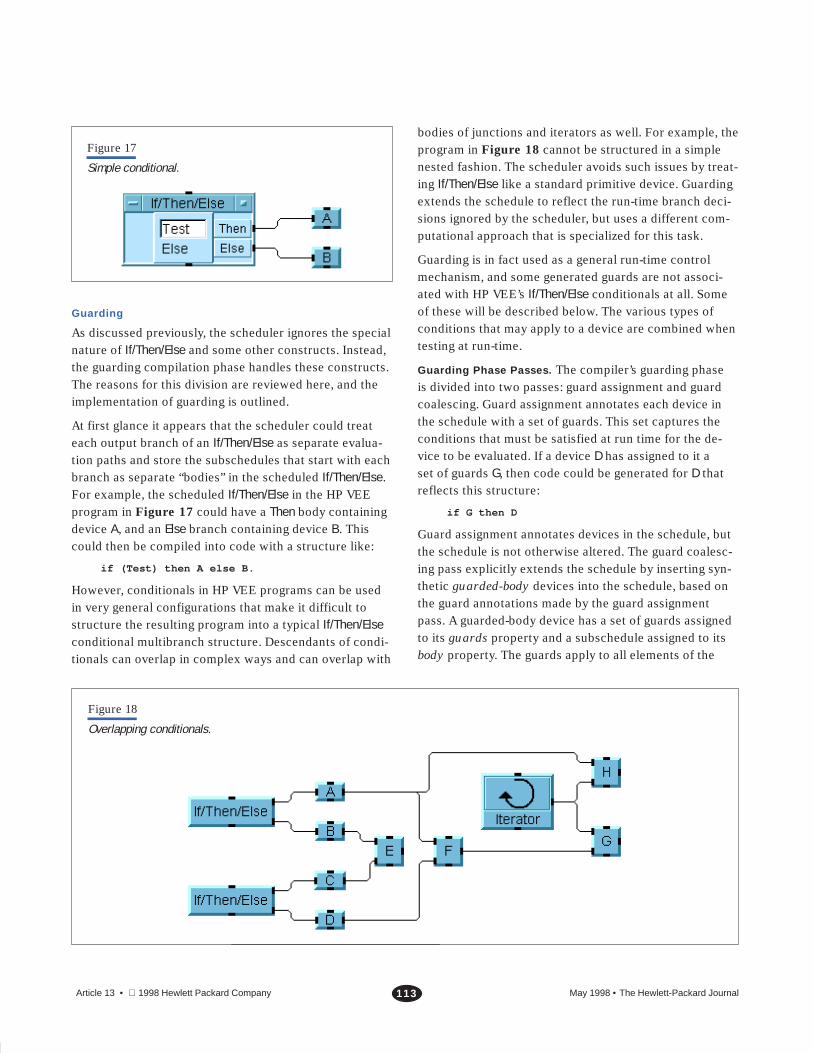
Figure 17
Simple conditional.
Guarding
As discussed previously, the scheduler ignores the specialnature of If/Then/Else and some other constructs. Instead,the guarding compilation phase handles these constructs.The reasons for this division are reviewed here, and theimplementation of guarding is outlined.
At first glance it appears that the scheduler could treateach output branch of an If/Then/Else as separate evalua-tion paths and store the subschedules that start with eachbranch as separate “bodies” in the scheduled If/Then/Else.For example, the scheduled If/Then/Else in the HP VEEprogram in Figure 17 could have a Then body containingdevice A, and an Else branch containing device B. Thiscould then be compiled into code with a structure like:
if (Test) then A else B.
However, conditionals in HP VEE programs can be usedin very general configurations that make it difficult tostructure the resulting program into a typical If/Then/Elseconditional multibranch structure. Descendants of condi-tionals can overlap in complex ways and can overlap with
bodies of junctions and iterators as well. For example, theprogram in Figure 18 cannot be structured in a simplenested fashion. The scheduler avoids such issues by treat-ing If/Then/Else like a standard primitive device. Guardingextends the schedule to reflect the run-time branch deci-sions ignored by the scheduler, but uses a different com-putational approach that is specialized for this task.
Guarding is in fact used as a general run-time controlmechanism, and some generated guards are not associ-ated with HP VEE’s If/Then/Else conditionals at all. Someof these will be described below. The various types ofconditions that may apply to a device are combined whentesting at run-time.
Guarding Phase Passes. The compiler’s guarding phaseis divided into two passes: guard assignment and guardcoalescing. Guard assignment annotates each device inthe schedule with a set of guards. This set captures theconditions that must be satisfied at run time for the de-vice to be evaluated. If a device D has assigned to it aset of guards G, then code could be generated for D thatreflects this structure:
if G then D
Guard assignment annotates devices in the schedule, butthe schedule is not otherwise altered. The guard coalesc-ing pass explicitly extends the schedule by inserting syn-thetic guarded-body devices into the schedule, based onthe guard annotations made by the guard assignmentpass. A guarded-body device has a set of guards assignedto its guards property and a subschedule assigned to itsbody property. The guards apply to all elements of the
Figure 18
Overlapping conditionals.

May 1998 • The Hewlett-Packard Journal114Article 13 • 1998 Hewlett Packard Company
body. After coalescing, guarding is explicitly representedin the schedule by the guarded-body devices and codegeneration only generates run-time conditions where aguarded-body occurs.
Although correct programs would result if coalescingadded a guarded-body to each guarded device individu-ally, the reason for a separate coalescing pass is optimiza-tion. Coalescing combines guard sets from adjacentdevices into a single guarded-body whose body is a multi-element segment of the schedule. This avoids many re-dundant run-time conditionals.
To illustrate the redundancy removed by guard coalesc-ing, consider two adjacent devices D1 and D2, bothguarded by the same set of guards G. Without coalescing
if G then D1
if G then D2
is generated. With coalescing,
if G then (D1; D2)
is generated. More elaborate coalescing can be per-formed. For example, if D1 is guarded by G, and D2 isguarded by G�H, then
if G then (D1; if H then D2)
can result. This last example would be represented in theschedule with nested guarded-body devices of the form:
Guarded-Body[G, (D1, Guarded-Body[H, (D2)])].
As mentioned previously, when possible the HP VEE pro-gram graph is scheduled in a relatively depth-first order toimprove efficiency of run-time guard evaluation. The rea-soning is that the set of guards for a device is usually asuperset of the guards of each of its parents, so schedul-ing devices adjacent to their ancestors increases the likeli-hood that adjacent devices have common guards. Thisworks well for coalescing.
Guard Assignment for If/Then/Else. Guard assignment forIf/Then/Else constructs operate on the list of devices pro-duced by the scheduler. Recall that devices in the sched-ule occur in an order such that when considering a partic-ular device in the schedule, all devices that produce dataconsumed by that device will occur earlier in the schedule(except if there is feedback). So a dependency-order tra-versal of the HP VEE program graph can be accomplishedby a simple walk down the schedule list. When we getto a device, we know that its parents have already beenprocessed.
As described in the section “If/Then/Else” on page 103, anIf/Then/Else fires a single output pin. Guarding implementsthe branching implied by this single-pin firing behavior byassociating a unique boolean variable, called a guard,with each output pin of the If/Then/Else. Before the expres-sions of an If/Then/Else are evaluated, the guards for all thepins are set to False. When it is determined which pinfires, only the guard associated with that pin is set to True.
Note that since an If/Then/Else can have any number ofconditions (and hence, output pins), a single booleanvariable for an If/Then/Else is not adequate. A single multi-valued flag could be used instead, but then instead ofdirectly testing its value (True or False), a test would haveto use the value resulting from a comparison of the vari-able with an appropriate value. We will assume here thatmultiple boolean variables are used.
The basic idea of the guard assignment algorithm is totraverse the schedule list visiting each device, in order,and for each such device D, consider all the direct parentsof the device. The parent devices will already have beenprocessed because of the schedule ordering. The guardsfrom the guards set of each of D’s direct parents areadded to the guards set of D. Also, if a direct parent of Dis an If/Then/Else device, the guard associated with eachIf/Then/Else output pin that is directly connected to D isalso added to the guards set of D. Figure 19 gives a moredetailed sketch of the algorithm.
Other Guarding Considerations. A number of importantpoints have been omitted in the presentation of the guardassignment algorithm. First, it does not address the factthat the schedule is not actually a flat list, but instead is ahierarchical structure because schedule segments arestored as the bodies of devices such as junctions and iter-ators. One must consider the relationship between theguards on a hierarchical device and the guarding of thebody of the device. Also, the interpretation of the guardsset must be clarified. These points are related.
First, consider the meaning of the guards sets. These aresets of individual guard objects, where each guard repre-sents a Boolean valued variable. For HP VEE programswithout junctions, a guards set can be interpreted as aconjunction (logical AND) of the individual guards in theset. This is because after the graph transformations per-formed earlier in the compilation (see section “Trans-formations,” page 107), all nonjunctions the compiler seesmust have data on all their input pins to run. The guards
May 1998 • The Hewlett-Packard Journal115Article 13 • 1998 Hewlett Packard Company
Figure 19
Basic guard assignment for If/Then/Else.
// These do not have specified return values.
Guard–Assignment (Schedule) { // Schedule is a list of devices. if (Schedule not Empty) Assign–Guards–to–Device(first(Schedule)) Guard–Assignment(rest(Schedule))}
Assign–Guards–to–Device (D) { // D is a device. for each input pin IP of D OP <– output–pin–connected–to(IP) Parent <– device–attached–to(OP) guards(D) <– guards(D) guards(Parent) if (Parent is an IF/Then/Else device) guards(D) <– guards(D) {guard(OP)}
inherited from parent devices represent the conditionsneeded for each parent to run, and also for direct If/Then/Else parents to place data on the appropriate lines. Thus,having data on all input lines requires all the guards to betrue.
A problem arises when HP VEE programs contain junc-tions. Junctions can run when any subset of their inputshave data, so the guards on junctions must be disjunctive(logical OR) instead of conjunctive. If we allow both con-junctive and disjunctive guarding, the guard sets must bereplaced with potentially complex boolean expressions(using conjunctions and disjunctions). We show how tosolve this problem below.
Guards assigned to an iterator device should not be prop-agated into the iterator body. If the guards on the iteratordevice are false, the iterator will be skipped, so the bodywill be skipped as well. If the guards are true, the iterator
and its body will run. In general, the body implicitly inher-its the effect of the guards on the iterator. This works forjunction bodies as well, so that the disjunctive guardingimplied by junction semantics does not need to produceany explicit guards in the junction body. We can concludefrom what we have discussed so far that guards do notneed to propagate into the bodies of junctions or iterators,and the guard set can indeed be considered to represent aconjunction.
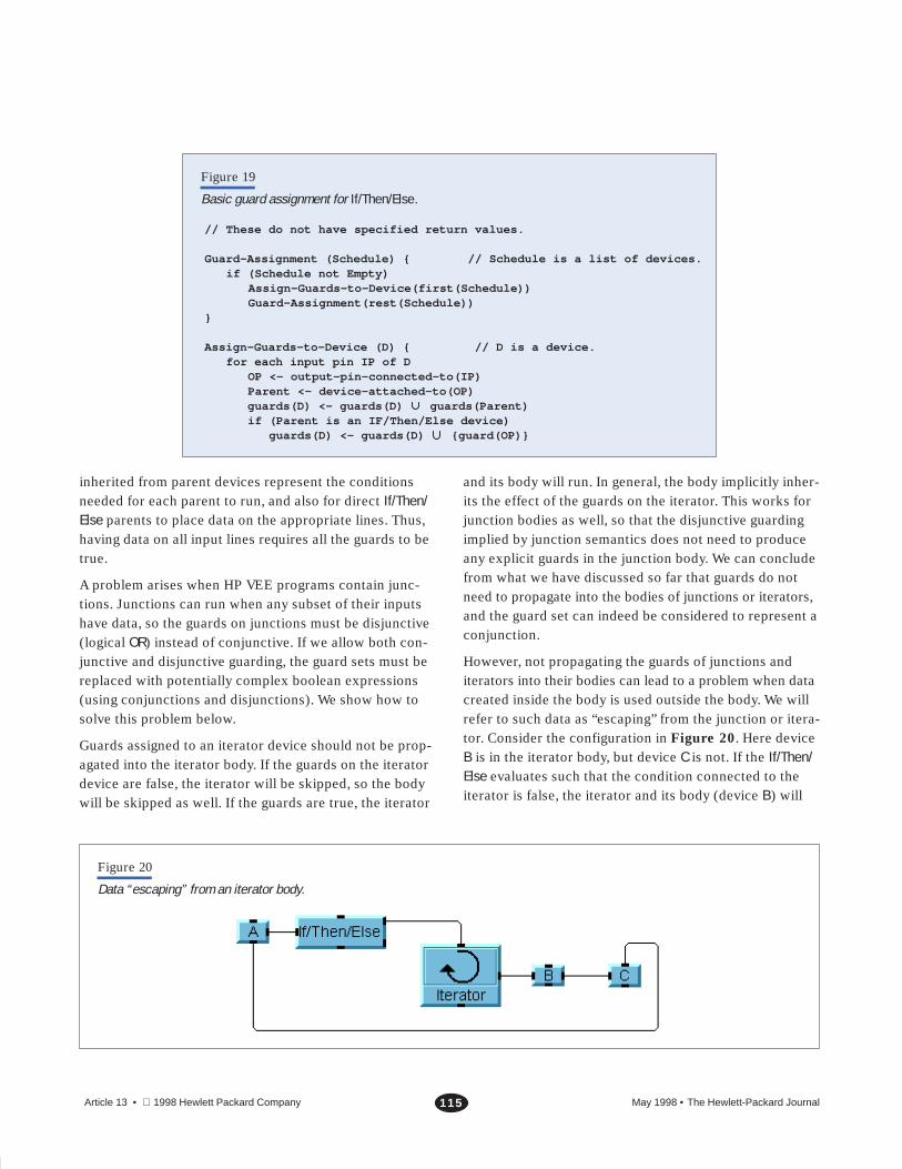
However, not propagating the guards of junctions anditerators into their bodies can lead to a problem when datacreated inside the body is used outside the body. We willrefer to such data as “escaping” from the junction or itera-tor. Consider the configuration in Figure 20. Here deviceB is in the iterator body, but device C is not. If the If/Then/Else evaluates such that the condition connected to theiterator is false, the iterator and its body (device B) will
Figure 20
Data “escaping” from an iterator body.
May 1998 • The Hewlett-Packard Journal116Article 13 • 1998 Hewlett Packard Company
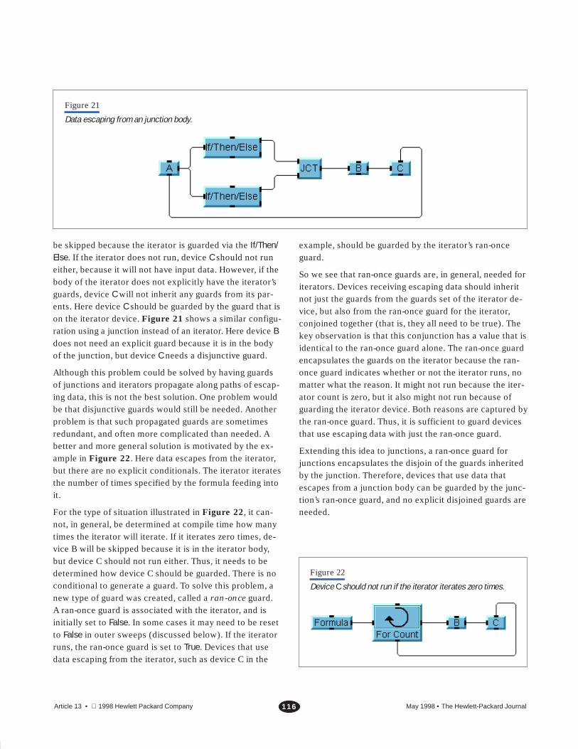
Figure 21
Data escaping from an junction body.
be skipped because the iterator is guarded via the If/Then/Else. If the iterator does not run, device C should not runeither, because it will not have input data. However, if thebody of the iterator does not explicitly have the iterator’sguards, device C will not inherit any guards from its par-ents. Here device C should be guarded by the guard that ison the iterator device. Figure 21 shows a similar configu-ration using a junction instead of an iterator. Here device Bdoes not need an explicit guard because it is in the bodyof the junction, but device C needs a disjunctive guard.
Although this problem could be solved by having guardsof junctions and iterators propagate along paths of escap-ing data, this is not the best solution. One problem wouldbe that disjunctive guards would still be needed. Anotherproblem is that such propagated guards are sometimesredundant, and often more complicated than needed. Abetter and more general solution is motivated by the ex-ample in Figure 22. Here data escapes from the iterator,but there are no explicit conditionals. The iterator iteratesthe number of times specified by the formula feeding intoit.
For the type of situation illustrated in Figure 22, it can-not, in general, be determined at compile time how manytimes the iterator will iterate. If it iterates zero times, de-vice B will be skipped because it is in the iterator body,but device C should not run either. Thus, it needs to bedetermined how device C should be guarded. There is noconditional to generate a guard. To solve this problem, anew type of guard was created, called a ran-once guard.A ran-once guard is associated with the iterator, and isinitially set to False. In some cases it may need to be resetto False in outer sweeps (discussed below). If the iteratorruns, the ran-once guard is set to True. Devices that usedata escaping from the iterator, such as device C in the
example, should be guarded by the iterator’s ran-onceguard.
So we see that ran-once guards are, in general, needed foriterators. Devices receiving escaping data should inheritnot just the guards from the guards set of the iterator de-vice, but also from the ran-once guard for the iterator,conjoined together (that is, they all need to be true). Thekey observation is that this conjunction has a value that isidentical to the ran-once guard alone. The ran-once guardencapsulates the guards on the iterator because the ran-once guard indicates whether or not the iterator runs, nomatter what the reason. It might not run because the iter-ator count is zero, but it also might not run because ofguarding the iterator device. Both reasons are captured bythe ran-once guard. Thus, it is sufficient to guard devicesthat use escaping data with just the ran-once guard.
Extending this idea to junctions, a ran-once guard forjunctions encapsulates the disjoin of the guards inheritedby the junction. Therefore, devices that use data thatescapes from a junction body can be guarded by the junc-tion’s ran-once guard, and no explicit disjoined guards areneeded.
Figure 22
Device C should not run if the iterator iterates zero times.
May 1998 • The Hewlett-Packard Journal117Article 13 • 1998 Hewlett Packard Company
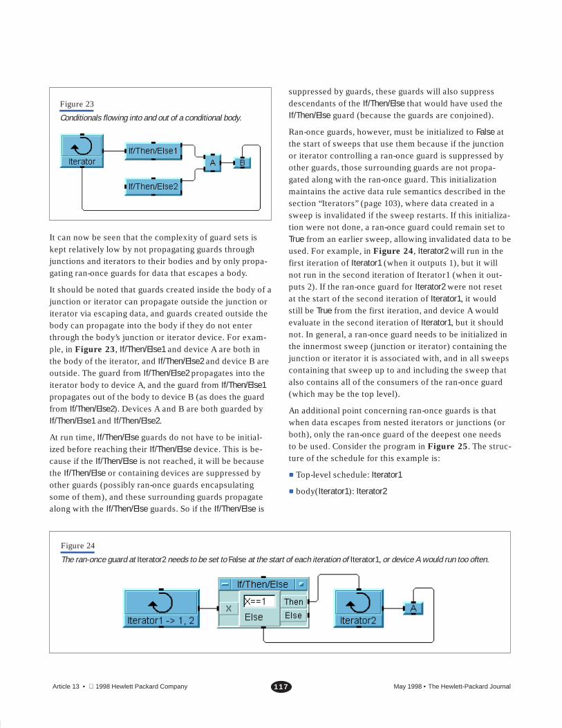
Figure 23
Conditionals flowing into and out of a conditional body.
It can now be seen that the complexity of guard sets iskept relatively low by not propagating guards throughjunctions and iterators to their bodies and by only propa-gating ran-once guards for data that escapes a body.
It should be noted that guards created inside the body of ajunction or iterator can propagate outside the junction oriterator via escaping data, and guards created outside thebody can propagate into the body if they do not enterthrough the body’s junction or iterator device. For exam-ple, in Figure 23, If/Then/Else1 and device A are both inthe body of the iterator, and If/Then/Else2 and device B areoutside. The guard from If/Then/Else2 propagates into theiterator body to device A, and the guard from If/Then/Else1propagates out of the body to device B (as does the guardfrom If/Then/Else2). Devices A and B are both guarded byIf/Then/Else1 and If/Then/Else2.
At run time, If/Then/Else guards do not have to be initial-ized before reaching their If/Then/Else device. This is be-cause if the If/Then/Else is not reached, it will be becausethe If/Then/Else or containing devices are suppressed byother guards (possibly ran-once guards encapsulatingsome of them), and these surrounding guards propagatealong with the If/Then/Else guards. So if the If/Then/Else is
suppressed by guards, these guards will also suppressdescendants of the If/Then/Else that would have used theIf/Then/Else guard (because the guards are conjoined).
Ran-once guards, however, must be initialized to False atthe start of sweeps that use them because if the junctionor iterator controlling a ran-once guard is suppressed byother guards, those surrounding guards are not propa-gated along with the ran-once guard. This initializationmaintains the active data rule semantics described in thesection “Iterators” (page 103), where data created in asweep is invalidated if the sweep restarts. If this initializa-tion were not done, a ran-once guard could remain set toTrue from an earlier sweep, allowing invalidated data to beused. For example, in Figure 24, Iterator2 will run in thefirst iteration of Iterator1 (when it outputs 1), but it willnot run in the second iteration of Iterator1 (when it out-puts 2). If the ran-once guard for Iterator2 were not resetat the start of the second iteration of Iterator1, it wouldstill be True from the first iteration, and device A wouldevaluate in the second iteration of Iterator1, but it shouldnot. In general, a ran-once guard needs to be initialized inthe innermost sweep (junction or iterator) containing thejunction or iterator it is associated with, and in all sweepscontaining that sweep up to and including the sweep thatalso contains all of the consumers of the ran-once guard(which may be the top level).
An additional point concerning ran-once guards is thatwhen data escapes from nested iterators or junctions (orboth), only the ran-once guard of the deepest one needsto be used. Consider the program in Figure 25. The struc-ture of the schedule for this example is:
� Top-level schedule: Iterator1
� body(Iterator1): Iterator2
Figure 24
The ran-once guard at Iterator2 needs to be set to False at the start of each iteration of Iterator1, or device A would run too often.

May 1998 • The Hewlett-Packard Journal118Article 13 • 1998 Hewlett Packard Company
Figure 25
Data escaping from nested iterators.
� body(Iterator2): If/Then/Else1, Iterator3, B
� body(Iterator3): If/Then/Else2, Iterator4
� body(Iterator4): A
Since B uses data created in Iterator4, B needs to beguarded by the ran-once guard for Iterator4. It does not,however, need to also be guarded by the ran-once guardof Iterator3, even though the data used by B is escapingfrom both Iterator4 and Iterator3. The ran-once guard forIterator3 is not needed at all in this example. The ran-onceguard for Iterator4 must be initialized to False at the startof each iteration of Iterator2 and Iterator3. It is set to Trueat the start of the first iteration of Iterator4. It is not neces-sary to set it at the start of each iteration of Iterator4, otherthan the first iteration, since its value cannot change dur-ing Iterator4’s execution. The ran-once guard does notneed to be initialized by Iterator1 or at the top level, be-cause it is not used at those levels. Also, a guard fromIf/Then/Else1 will guard Iterator3 and B, and a guard fromIf/Then/Else2 will guard Iterator4.
An extended version of Assign-Guards-to-Device fromFigure 19 appears in Figure 26. This version imple-ments the methods discussed above.
Guards are used for control of other constructs as well.One example is error pins. An error output pin can be
placed on many HP VEE devices. If present, errors in thedevice are trapped by the system and cause the error pinto fire instead of the other output pins. If there is no errorthe other pins fire and their error pin does not. From thecompiler’s point of view, any device with an error pin issimilar to a two-branch If/Then/Else, except that the noner-ror branch can be associated with any number of outputpins. Thus, guards are used to implement error outputs ina similar manner to the implementation of If/Then/Else.The guards are set by run-time error trapping constructscompiled with the implementation of the device with theerror pin.
Sometimes guards can be optimized away at compile time.Ran-once guards are only needed for escaping data, so ifno data escapes they do not have to be set. If data doesescape, but it can be verified at compile time that the in-nermost escaped sweep runs sufficiently often comparedto all the devices that consume the escaped data, the ran-once guard can be omitted. For example, if an iterator isknown to run a fixed nonzero number of times, and thereare no guards acting on it (directly or indirectly), then itdoes not need to have a ran-once guard for any escapingdata because it will verifiably run at least once. There aremany other situations where various types of guards canbe optimized away, although in practice it can be complex.

May 1998 • The Hewlett-Packard Journal119Article 13 • 1998 Hewlett Packard Company
Figure 26
Guard assignment.
Assign–Guards–to–Device (D) { // D is a device. if (D is a junction or iterator) // Assign guards to body before D itself so that body won’t // inherit guards from D. Guard–Assignment(body(D)) for (each input pin IP of D) OP <– output–pin–connected–to(OP) Parent <– device–attached–to(OP) guards(D) <– guards(D) guards(Parent) if (Parent is an If/Then/Else device) guards(D) <– guards(D) {guards(OP)} if (Parent is in a junction or iterator body that D is not in) RanOnce–Guard <– ran–once–guard(deepest–junction–or–iterator–in(Parent)) guards(D) <– guards(D) {RanOnce–Guard} record <Parent,D,RanOnce–Guard> for RanOnce initialization}
Type Annotation
Type annotation is a phase of the prototype HP VEE com-piler in which every pin of every device in an HP VEEprogram is annotated with a description of the types ofdata it will handle at run time. The type annotations canoften be used to generate more efficient run-time code.Some run-time checks can be eliminated and compositedata objects can be replaced by hardware supported rep-resentations (for example, real numbers). The type de-scriptions are conservative approximations in that theyerr on the safe side. For example, we may obtain a con-servative approximation that some data input pin is al-ways a real or integer scalar, when in fact it could only bea real scalar.
Recall from the discussion of HP VEE data types that dataobjects in HP VEE are typed, but pins and connectionsare not typed. In HP VEE 3.2 the data objects have fieldsthat specify the type information. Also, recall that mostHP VEE devices will handle many different types of dataas input. Every time a device is executed by the HP VEE3.2 interpreter, the following steps typically occur:
1. The type of each input value is ascertained and com-pared against the pin’s required type. A conversionmay need to be performed, possibly allocating andinitializing a new data object.
2. A check is made to determine whether input valuesneed to be promoted to a common type. Again, inputvalues may need to be converted.
3. The data inputs, or their conversions, are used toperform the computation.
4. The final result is injected into a data object, alongwith type information.
When executing a simple numerical device, these sorts ofextraction, conversion, and injection operations on dataobjects can account for a substantial percentage of thedevice’s execution time. With type annotation, unneces-sary extraction, conversion and injection operations canoften be eliminated. The result can be very efficient nu-merical code that uses standard hardware-supported datarepresentations such as real and integer.
The type descriptions generated during type annotationare sets of ordered pairs. Each pair specifies a class ofvalues and a class of shapes, as shown in Table I. A typedescription represents a disjunction of pairs, as shown inTable II. Type descriptions are normalized so that thenumber of pairs is minimized. Normalizing a type descrip-tion does not change its meaning, as shown in Table III.

May 1998 • The Hewlett-Packard Journal120Article 13 • 1998 Hewlett Packard Company
Table IType Descriptions
Pair Meaning
<real, scalar> Data is a real scalar
<real, array> Data is a real array of some dimension
<real, array-1d> Data is a real one-dimensional array
<real, any> Data is a real array or real scalar
<real, any> Data in anything
<any, array> Data is an array, but type is unknown
Table IIDisjunction of Pairs in Type Descriptions
Type Description Meaning
{<real, scalar>, <integer, scalar>} Data is a real or integer scalar
{<real, scalar>} Data is a real scalar
{<real, scalar>, <nil, any>} Data is a real scalar or nil
Table IIINormalization of Type Descriptions
Type Description Normalized Type Description
{<real, scalar>, <real, any>} {<real, any>}
{<real, scalar>, <real, array>} {<real, any>}
{<real, scalar>, <integer, any>} {<real, scalar>, <integer, any>}
The type descriptions are ordered by a�b if the set ofvalues described by a is a proper subset of the values de-scribed by b. The bottom element of the ordering is {} andthe top element of the ordering is {<any, any>}.
Determining the type description for every pin of everydevice in an HP VEE program can be viewed as executingthe HP VEE program over the abstract domain of typedescriptions rather than over the standard domain of val-ues. In this view, devices take type descriptions as inputand compute appropriate type descriptions as outputs.The resulting type descriptions are propagated to descen-dants for further annotation. This notion of computingwith abstract values is sometimes called abstract inter-
pretation. An annotated program is shown in Figure 27.In this figure, the addition device takes {<integer, scalar>}and {<real, scalar>} and produces {<real, scalar>} as the
result. The reason for this is that the standard additiondevice promotes its inputs to a common type before com-puting the result, and the abstract addition device reflectsthis.
Figure 27
Example of type annotation.

May 1998 • The Hewlett-Packard Journal121Article 13 • 1998 Hewlett Packard Company
Since truth values cannot be determined from type de-scriptions, when performing type annotation we simplyignore all guard and control values and propagate typedescriptions to all output pins.
Type annotation is performed by traversing the scheduleroutput and determining type annotations for every devicethat is encountered. Because of feedback loops, type an-notations can change on input pins of devices that havealready been visited in the traversal. Thus, the type anno-tator may need to traverse the scheduler output multipletimes until all type annotations have stabilized. The sub-sequent traversals are very efficient because only devicesthat need to have their output pin annotations updatedare redone. Type annotations do eventually stabilize,because when a type description, d, is changed, it is re-placed by a type description that is strictly greater than din the ordering. Since there are only a finite number oftype descriptions, only a finite number of changes arepossible.
Code Generation
The internal structure that results from the sequence ofgraph transformations, scheduling, guarding, and typeannotation, is similar in form to an annotated parse treethat might be produced by a conventional compiler. Tocomplete the compilation, target code is produced fromthis structure. If appropriate libraries of HP VEE built-inroutines exist, most of the compiled internal structure canbe straightforwardly mapped to any conventional program-ming language, such as C. The mapping may be difficultfor error trapping (for error pins) and the implementationof the Fork construct. Fork should map to a construct (orconstructs) to implement thread creation and destruction.Error trapping is built-in or can be implemented in mostprogramming systems, and threads have become reason-ably common. If the generated code is interpreted, thread-ing is easy to implement.
To generate code for different target languages, only thecode generator needs to be modified. This is a relativelysmall part of the compiler. Prototype code generators forC, and for an interpreted byte-code, have been imple-mented. C generators have been written to produce stand-alone programs for subsets of HP VEE and to produce C
code to be compiled and dynamically loaded into a run-ning HP VEE 3.2 session. A byte-code generator was writ-ten to produce a stream of byte code to a file or in-memory array. A simple interpreter running inside HPVEE can run the byte code. An advantage of the byte-codegenerator over the C code generator is that an externalcompiler is not needed. Another advantage of interpreta-tion is that program development features such as singlestepping and tracing are easier to implement, especially inthe context of running programs inside the HP VEE devel-opment system.
Conclusion
An overview of the major components of a compiler forHP VEE 3.2 has been presented. Although many detailswere omitted, the fundamental algorithms for a largeclass of programs have been explained. The five compilercomponents are graph transformation, device scheduling,guard assignment, type annotation, and code generation.These components combine to implement the controlsemantics explicitly or implicitly specified in an HP VEEprogram. These semantics were also described. A com-piler based on the prototype compiler has now become anintegral part of HP VEE 4.0.
Acknowledgments
A compiler for HP VEE was originally suggested to us byRandy Coverstone, our department manager at Hewlett-Packard Laboratories. Wes Higaki and Bill Shreve alsoprovided valuable management support. Special mentiongoes to the following Measurement Systems Division engi-neers from the HP VEE product team: Jim Bachman, KenColasuonno, John Dumais, and Susan Wolber. These fourhad the difficult task of understanding our prototype andmaking it into a product. The result of their efforts is thecompiler in HP VEE 4.0. Bill Hunt and Randy Bailey wereengineers on the Measurement Systems Division HP VEEteam who worked with us early in the project. Bill helpedus integrate early versions of the compiler with HP VEE,and supplied much other help as well. John Bidwell, BillHeinzman, and Chuck Heller also provided encourage-ment and support.

May 1998 • The Hewlett-Packard Journal122Article 13 • 1998 Hewlett Packard Company
References
1. R. Helsel, Cutting Your Test Development Time with HP
VEE: An Iconic Programming Language, P T R Prentice Hall,Englewood Cliffs, NJ, 1994.
2. Hewlett-Packard Journal, Vol. 43, no. 5, October 1992,pp. 72-88.
3. D. E. Knuth, The Art of Computer Programming, Vol. 1/Funda-mental Algorithms, Addison-Wesley, 1973. W W W
Online Information
More information about HP VEE can be found at:
http://www.hp.com/go/HPVEE
� Go to Journal Home Page