a compendium of recent optocoupler radiation test data · abstract--we present a compendium of...
TRANSCRIPT

Abstract--We present a compendium of optocoupler radiation testdata including data on neutron, proton and heavy ion DisplacementDamage (DD), Single Event Transients (SET) and degradation dueto Total Ionizing Dose (TID). Proton data includes ionizing andnon-ionizing damage mechanisms.
I. INTRODUCTION
Optocouplers, also known as optoisolators, are hybrid devicestypically used by spaceflight designers to provide electricalisolation between circuits such as subsystem-to-subsysteminterfaces. These devices consist of a transmitter [lightemitting diode (LED)] coupled to a receiver equipped with aphoto-intrinsic-n (PIN) photodiode or phototransistordetector. Many devices also have additional supportcircuitry. Figure 1 illustrates a typical optocoupler [1]. Itshould also be noted that optocouplers are not just standalonedevices. They are often components in other devices such asDC/DC converters.
This compendium compiles optocoupler radiation data thathas been gathered by several government and industry testorganizations testing at several facilities and using varioustest methods.
Figure 1: Typical Optocoupler Block Diagram
II. RADIATION ISSUES
There are three major radiation issues affecting optocouplersfor space flight applications: displacement damage, singleevent transients and total ionizing dose.
A. Displacement DamagePrimarily neutrons and protons cause DD. Protonspredominate the natural space environment and contribute toboth TID and DD. Thus, depending on a device’s primarydegradation mode, proton tests can yield results that are eithernearly identical to Co-60 TID tests or can show substantiallymore degradation than would be expected from TID alone.Neutrons are important primarily for avionics and manmadenuclear environments and contribute almost exclusively to
DD. Although many optical components degrade from DD,the optocoupler devices most susceptible to such degradationare amphoterically doped or single heterojunction LEDs[2,3,4]. Double heterojunction LEDs appear to besubstantially less sensitive to DD [4,5,6]. Concerns about DDissues in optocouplers were first noted when in-flightdegradation of optocouplers on the TOPEX/Poseidon satelliteled to the failure of several non-critical status signal datapaths. Rax, et al. [2], first described this radiation issue.Further investigations to characterize DD effects inoptocouplers are discussed in [4,6,7,8,9]. DD affects thecurrent transfer ratio (CTR) of optocouplers and may alsoaffect other performance parameters such as timing. CTR isdefined as the ratio of collector current (IC) in thephototransistor or photodiode to the LED forward current(IF).
F
C
II
CTR = [Eq. 1]
Issues such as particle energy, mapping of test results to in-flight predictions, proper interpretation of application-specifictest data, initial device CTR, sample-to-sample variation,temperature and aging effects all must be considered fordevice selection and use.
B. Single Event TransientsSETs are induced by protons and heavy ions in higher
speed devices (>1 Mbps) and induced by heavy ions in slowerdevices. The first incident that brought the SET issue foroptocouplers to the forefront was a series of anomaliesobserved by NASA's Hubble Space Telescope (HST)following the installation of two instruments that containedhigh-speed optocouplers during Servicing Mission 2. Theseanomalies prompted an investigation and subsequent protontesting that found SET sensitivity in certain optocouplers [1].Further work has since explored the mechanisms of thesetransients, their magnitude, duration, and SET cross sectionsas a function of device performance, incident particle,incident beam angle, and a variety of application-specificconditions [7,10,11].
A Compendium of Recent Optocoupler Radiation Test DataK.A. LaBel1, S.D. Kniffin2, R.A. Reed1, H.S. Kim3, J.L. Wert4, D.L. Oberg4, E. Normand4,
A.H. Johnston5, G.K. Lum6, R. Koga7, S. Crain7, J.R. Schwank8, G.L. Hash8,S. Buchner9, J. Mann9, L. Simpkins9, M. D’Ordine10, C.A. Marshall1,
M.V. O’Bryan11, C.M. Seidleck11, L.X. Nguyen11, M.A. Carts11, R.L. Ladbury2, J.W. Howard3
NASA/Goddard Space Flight Center1; Orbital Sciences Corporation2;Jackson and Tull Chartered Engineers3; Boeing Corporation4; NASA/Jet Propulsion Laboratory5;
Lockheed Martin Space Systems Company, Missiles and Space Operation 6;The Aerospace Corporation7; Sandia National Laboratories8; Naval Research Laboratories9;
Ball Aerospace and Technologies Corporation10; Raytheon Systems Corporation11
C. Total Ionizing DoseHistorically, TID was the prime radiation concern foroptocouplers. TID issues for optocouplers are well knownand usually serve as the basis for parts procurement decisions.Optocoupler TID testing typically utilizes Co-60 sources(ionizing radiation). However, in some cases proton damagetesting, which allows measurement of the combined effects ofTID and DD, has been used in place of Co-60. Theparameter most sensitive to TID is usually the CTR. In someapplications, derating the part sufficiently to compensate forthe expected CTR loss during the mission lifetime canmitigate the CTR degradation [5].
III. TEST FACILITIES
Table 1 shows the test facilities utilized in testing parts by theorganizations contributing to this compendium. Protontesting was conducted at the Harvard Cyclotron Laboratory(HCL), the Indiana University Cyclotron Facility (IUCF), theLoma Linda University Medical Center (LLUMC), the TRI-University Meson Facility (TRIUMF), University ofCalifornia at Davis, Crocker Nuclear Laboratories(UCD/CNL), and Lawrence Berkley Laboratories (LBL).Heavy ion testing was conducted at LBL, BrookhavenNational Laboratories (BNL) and the Michigan StateUniversity National Superconducting Cyclotron Laboratory(MSU/NSCL). Neutron testing was performed at the SandiaNational Laboratory Pulse Reactor Facility (SPR). TIDtesting was performed at Sandia National LaboratoryRadiation Hardness Assurance Department (SNL/RHA).
TABLE 1: TEST FACILITIES AND PARTICLES
Facility Particle Particle Energies Used
HCL Proton 73 – 149MeV
IUCF Proton 54 – 197MeV
LLUMC Proton 51MeV
TRIUMF Proton 50 – 500MeV
UCD/CNL Proton 26.6 – 63MeV
LBL Proton/He 35 – 55MeV p+, 48MeV He
BNL Heavy Ion57MeV Li-7, 110MeV C-12, 150MeVF-19, 210MeV Cl-35, 227MeV Ti-48,
278MeV Ni-58
MSU/NSCL Heavy Ion240MeV He-4, 720MeV C-12,
1200MeV Ne-20, 2160MeV Ar-36,5040MeV Kr-84, 7740MeV Xe-129
SPR Neutron TRIGA* Reactor, pulse spectrum
SNL/RHA Co-60 γ 1.17, 1.33MeV*TRIGA = Training, Research, Isotopes, General Atomicsnuclear reactor.
IV. TEST METHODS
Eight organizations have tested optocouplers for variouseffects at several different test facilities. The parameter ofinterest determines how the device is set up for testing. Alldevices presented were tested at nominal room temperatureunless otherwise indicated (some results were at 125°C).
Table 2 presents an overview of the test methods used byeach organization. All methods, results and data use thefollowing abbreviation or acronym conventions:CTR = IC/IFCTRO = Initial (pre-rad) CTRCTR/CTRO = Normalized CTRDUT = Device Under TestGSFC = NASA Goddard Space Flight CenterHP = Hewlett Packard (now Agilent)IC = Output current of the photodiode or phototransistorID = Photovoltaic MOSFET Relay Drain CurrentIF = Forward current of the LEDJPL = Jet Propulsion Laboratorieskbps = kilobits per secondLDC = Lot Date CodeLED = Light-Emitting DiodeLMSSC MSO = Lockheed Martin Space Systems Company,
Missiles and Space OperationMbps = megabits per secondMfg = ManufacturerMii = MicropacMOSFET = Metal-Oxide-Semiconductor Field-Effect TransistorNRL = Naval Research LaboratoriesPV Relay = Photo Voltaic relayRC = Load applied as input feedbackRF, CF = Passive filter (resistor/capacitor combination) for SET
testingRL = The forward load applied to the input to vary IF for a constantVCCRT = Room TemperatureSN = Serial NumberSNL = Sandia National LaboratoriesTI = Texas InstrumentsVCC = Voltage drop across the load and LEDVCE = Voltage drop across the collector/emitter of the photodiode or
phototransistor (receiver)VD = Photovoltaic MOSFET Relay Drain VoltageVO = Voltage drop across the collector of the photodiode or
phototransistor (receiver)
A. Displacement Damage TestingIn displacement damage testing, CTR, is typically theparameter of interest. The device is typically set up as shownin Figure 2. Testing is usually done in step irradiations eitherbiased or unbiased. Electrical measurements are generallymade after each step of the irradiation procedure,concentrating on certain parameters (IF, IC, VCE, and VCC).Usually, one parameter is varied while the others are heldconstant. Some measurements have been made in-situ withone bias condition being maintained during the testing (nosweep). See Table 2 for test conditions used by each testorganization.

VCC
RL RC
VO
VCE
Optocoupler
IF IC
Figure 2: Schematic of experimental setup to measure CTR degradation [7].
B. SET TestingSET testing is generally performed using a setup similar tothat illustrated in Figure 3. The bias condition should be suchthat the LED is off. When the LED is biased on, SETsensitivity is negligible [1]. Transients can be measureddirectly at the output of the optocoupler (analog SET), theoutput of a follow-on TTL device (digital SET), or someother filtering device. Note that any RC filter must beaddressed in the transient data assessment as it directly affectsthe transient pulse shape.
VCC (+5Vdc)
Input (LEDis biased off)
RC
CF
RF
Digital SETAnalog SET
Output
Optocoupler
RL
Figure 3: Schematic representation of a SET test circuit showing a filternetwork and two probe locations for analog and digital transient capture [7].
C. Total Ionizing Dose TestingThe devices tested for TID by SNL were unbiased andirradiated with Co-60 gamma rays stepwise to 1Mrad(Si).The electrical performance of these parts was tested betweensteps.
V. SUMMARY OF TEST RESULTS
All tests were performed at nominal room temperature unlessotherwise noted. Table 3 summarizes the proton, neutron andheavy ion DD results. For the “Results/Notes” column, thenumber given is the fluence (particles/cm2) of the particleindicated. If the part degraded, the fluence given representsthe level where degradation was first noted. If there was nodegradation, then the number given represents the end of testfluence. Table 4 summarizes the proton and heavy ion SETresults. If the part had no SET, the number is the total fluence(particles/cm2) given to the device. Table 5 summarizes theTID results. The “Results/Notes” section gives the onset ofdegradation.
Table 2. Test Methods
Organization Input VCE RC (Load) Note Parameters Measured ParticlesAerospace Sweep IF Constant Variable step irradiation CTR Protons, HeliumBall Aero Sweep IF Constant Variable step irradiation CTR Protons
Sweep IF Sweep Constant step irradiation CTROff Sweep Constant step irradiation LeakageSweep IF, Fixed VCC Constant Constant in situSweep IF, Fixed VCC Sweep Variable step irradiation
JPL Sweep IF Constant Constant step irradiation CTR ProtonsLMSSC MSO Constant Constant Constant step irradiation CTR ProtonsNRL Sweep IF Constant Constant step irradiation CTR ProtonsSRL Sweep IF Sweep Constant step irradiation CTR Neutrons
Organization Parameters Measured ParticlesGSFC SET Protons, Heavy IonsJPL SET Protons, Heavy IonsLMSSC MSO SET ProtonsNRL SET Protons
Organization Input VCE RC (Load) Note Parameters Measured ParticlesSNL Constant Sweep Constant step irradiation CTR Co-60 Gamma Rays
SET
Total Ionizing Dose
Note:
The part should be biased in such a way that the LED is off. If the LED is on, SET sensitivity is negligible [1].
Protons, Neutrons, Heavy IonsCTR, Switching, LeakageGSFC
Displacement Damage
Boeing Protons

Device Mfg LDC Device Speed Test Organization Test Facility Energy/Particles Used Results/Notes (particles/cm2)4N24 TI 8850 400kbps Aerospace LBL 45MeV Protons, 48MeV He CTR Degradation at 5.8x10¹⁰ p+, 5.2E8 He4N49 TI 9408 400kbps Aerospace LBL 35, 55MeV Protons CTR Degradation at 4.8x10⁹ 35MeV, 6.8x10¹⁰ 55MeV4N49 TI 9408 400kbps Aerospace LBL 55MeV Protons, 48MeV He CTR Degradation at 6.8x10¹⁰ p+, 5.2x10⁸ HeOLF400 Isolink 9713 400kbps Aerospace LBL 55MeV Protons No CTR degradation at 8.1x10¹¹
4N49 Mii 9518 400kbps Ball UCD/CNL 63MeV Protons CTR Degradation at 4.5x10¹⁰
OMT1062 Optek 9628 50kbps Ball UCD/CNL 63MeV Protons CTR Degradation at 4.5x10¹⁰
66092 Mii Unknown 400kbps Boeing UCD/CNL 63MeV Protons No CTR degradation at 3x10¹⁰
66099 Mii 9650 50kbps Boeing UCD/CNL 63MeV Protons Some CTR degradation at 3x10¹⁰
4N48 Mii 9550 400kbps Boeing UCD/CNL 63MeV Protons Degradation of CTR at 1x10¹⁰
4N48 Mii 9618 400kbps Boeing UCD/CNL 63MeV Protons Degradation of CTR at 1x10¹⁰
4N49 TI 8646 400kbps Boeing UCD/CNL 63MeV Protons Degradation of CTR at 1x10¹⁰
4N49 Mii 9327 400kbps Boeing UCD/CNL 63MeV Protons Degradation of CTR at 1x10¹⁰
4N49 Mii 9329 400kbps Boeing UCD/CNL 63MeV Protons Degradation of CTR at 1x10¹⁰
4N49 TRW 9439 400kbps Boeing UCD/CNL 63MeV Protons Degradation of CTR at 3x10¹⁰
4N49 Mii 9504 400kbps Boeing UCD/CNL 63MeV Protons Degradation of CTR at 1x10¹⁰
4N49 Mii 9511 400kbps Boeing UCD/CNL 63MeV Protons Degradation of CTR at 3x10¹⁰
4N49 Mii 9529 400kbps Boeing UCD/CNL 63MeV Protons Degradation of CTR at 1x10¹⁰
4N49 Mii 9550 400kbps Boeing UCD/CNL 63MeV Protons Degradation of CTR at 1x10¹⁰
4N49 Mii 9623 400kbps Boeing UCD/CNL 63MeV Protons Degradation of CTR at 1x10¹⁰
4N49 Mii 9648 400kbps Boeing UCD/CNL 63MeV Protons Degradation of CTR at 1x10¹⁰
4N55 HP 9337 400kbps Boeing UCD/CNL 63MeV Protons No CTR degradation to 3x10¹⁰
4N55 Mii 9623 400kbps Boeing UCD/CNL 63MeV Protons Some CTR degradation at 3x10¹⁰
6N134 Mii 9645 10Mbps Boeing UCD/CNL 63MeV Protons No Parametric degradation at 3x10¹⁰
6N140 HP 9711, 15, 16 400kbps Boeing UCD/CNL 63MeV Protons No CTR degradation to 3x10¹⁰
6N140 (66058) Mii 9623 400kbps Boeing UCD/CNL 63MeV Protons Degradation of CTR at 3x10¹⁰
DIH126 Dionics 9521 N/A Boeing UCD/CNL 63MeV Protons Degradation of Relay (PV MOSFET Relay) at 9x10⁹
FB00KBY Teledyne 9531 N/A Boeing UCD/CNL 63MeV Protons Degradation of Relay (PV MOSFET Relay) at 9x10⁹
HCPL-5231 HP 9632, 9633 2Mbps Boeing UCD/CNL 63MeV Protons No Parametric degradation at 3x10¹⁰
HCPL-5430 HP 9644 40Mbps Boeing UCD/CNL 63MeV Protons No Parametric degradation at 3x10¹⁰
HCPL-5431 HP 9618 40Mbps Boeing UCD/CNL 63MeV Protons No Parametric degradation at 3x10¹⁰
HCPL-5530 (4N55) HP 9642 400kbps Boeing UCD/CNL 63MeV Protons No CTR degradation to 3x10¹⁰
HCPL-5531 (4N55) HP 9632, 9633 400kbps Boeing UCD/CNL 63MeV Protons No CTR degradation to 3x10¹⁰
HCPL-5630 (6N134) HP 9716 10Mbps Boeing UCD/CNL 63MeV Protons No Parametric degradation at 3x10¹⁰
HCPL-5701 (6N140A) HP 9315 400kbps Boeing UCD/CNL 63MeV Protons Some CTR degradation at 3x10¹⁰
HCPL-5730 (6N140A) HP 9701 400kbps Boeing UCD/CNL 63MeV Protons No CTR degradation to 3x10¹⁰
OLH149 Isolink Unknown 400kbps Boeing UCD/CNL 63MeV Protons No CTR degradation to 3x10¹⁰
OLH249 Isolink Unknown 400kbps Boeing UCD/CNL 63MeV Protons No CTR degradation to 3x10¹⁰
OLH304 Isolink Unknown 1Mbps Boeing UCD/CNL 63MeV Protons No CTR degradation to 3x10¹⁰
OLH349 Isolink Unknown 1Mbps Boeing UCD/CNL 63MeV Protons No CTR degradation to 3x10¹⁰
OLH400 Isolink Unknown 400kbps Boeing UCD/CNL 63MeV Protons No CTR degradation to 3x10¹⁰
Table 3: Proton, Neutron and Heavy Ion Displacement Damage Summary

Device Mfg LDC Device Speed Test Organization Test Facility Energy/Particles Used Results/Notes (particles/cm2)66088 Mii Unknown 625kbps GSFC UCD/CNL 63MeV Protons No CTR degradation to 1x10⁹
66088 Mii Unknown 625kbps GSFC UCD/CNL 63MeV Protons Degradation of CTR at 2x10¹⁰
66099 Mii Unknown 50kbps GSFC TRIUMF 58MeV Protons No CTR degradation to 2x10¹⁰
66099 Mii Unknown 50kbps GSFC UCD/CNL 63MeV Protons Degradation of CTR at 5x10¹¹
66123 Mii Unknown 10Mbps GSFC TRIUMF 58MeV Protons No Parametric degradation to 2x10¹⁰
3C91C Mitel Unknown 200kbps GSFC UCD/CNL 63, 31, 21, 14MeV Protons Degradation of CTR at <1x10¹⁰ for all energies4N48 Mii Unknown 400kbps GSFC SPR Neutrons Degradation of CTR at 2x10¹¹
4N48 Optek Unknown 400kbps GSFC UCD/CNL 63MeV Protons Degradation of CTR at 2x10¹⁰
4N49 Mii Unknown 400kbps GSFC TRIUMF 58MeV Protons No CTR degradation to 2x10¹⁰
4N49 TI Unknown 400kbps GSFC UCD/CNL 63MeV Protons Degradation of CTR at 2x10¹⁰
6N134 HP Unknown 10Mbps GSFC SPR Neutrons No Parametric degradation to 8x10¹¹ 1MeV equiv. 6N140 Mii Unknown 400kbps GSFC TRIUMF 58MeV Protons No CTR degradation to 2x10¹⁰
HCPL-6651 (6N134) HP Unknown 10Mbps GSFC TRIUMF Various Protons No Parametric degradation at 2x10¹⁰
HSSR-7110 HP 9637 N/A GSFC UCD/CNL 63MeV Protons Leakage and On/Off Time degradation at 2.3x10¹¹
(Part is a Power MOSFET PV Relay)OLH249 Isolink Unknown 400kbps GSFC IUCF 195MeV Protons Degradation of CTR at 6x10¹¹
OLH400 Isolink Unknown 400kbps GSFC UCD/CNL 63MeV Protons Degradation of CTR at 4x10¹¹
OLS700 Isolink Unknown 1Mbps GSFC UCD/CNL 63MeV Protons Degradation of CTR at 3.8x10¹¹
P2824 Hamamatsu Unknown 333kbps GSFC TRIUMF, LLUMC, IUCF, SPR Various Protons, Neutrons
Degradation of CTR at 2x10¹⁰ (TRIUMF 58MeV p+), 1.7x10¹⁰ (LLUMC 52MeV p+), 2.5x10¹⁰ (IUCF 195MeV p+), 5.4x10¹⁰ (SPR 1MeV equiv. Neutrons)
4N49 Mii Unknown 400kbps JPL IUCF 192MeV Protons Degradation of CTR at 5x10¹⁰
4N49 Optek Unknown 400kbps JPL IUCF 192MeV Protons Degradation of CTR at 5x10¹⁰
OLH1049 Optek Special Process Unknown JPL UCD/CNL 50MeV Protons Degradation of CTR at 1x10¹⁰
OLH1049.0002 Optek Special Process Unknown JPL UCD/CNL 50MeV Protons Degradation of CTR at 1x10¹⁰
OLH1049.0003 Optek Special Process Unknown JPL UCD/CNL 50MeV Protons Degradation of CTR at 1x10¹⁰
4N35 Mii Unknown 400kbps LMSSC MSO IUCF 192MeV Protons Degradation of CTR at 5x10¹¹
4N49 Mii CEJG M9628 400kbps LMSSC MSO IUCF 192MeV Protons Degradation of CTR at 1x10¹¹
4N49 Mii 66092-101S special process 400kbps LMSSC MSO IUCF 192MeV Protons Degradation of CTR at 4x10¹¹
6N140 Mii 8836 8302401EC 31757 400kbps LMSSC MSO IUCF 192MeV Protons Degradation of CTR at 1x10¹¹
HCPL-2201 HP 9538 20Mbps LMSSC MSO IUCF 192MeV Protons No CTR degradation at 6x10¹¹
HCPL-2430 HP 9630 5Mbps LMSSC MSO IUCF 192MeV Protons No CTR degradation at 6x10¹¹
61082-300 photodiode Mii 9827 ~1Mbps LMSSC MSO HCL 73MeV Protons Ic degradation at 2x10¹⁰
62017 GS3040-3 LED Mii Unknown ~1Mbps LMSSC MSO HCL 73MeV Protons If degradation at 2x10¹⁰
OP224 LED Optek GaAlAs IR, 890nm ~1Mbps LMSSC MSO HCL 73MeV Protons If degradation at 2x10¹⁰
OP604 phototransistor Optek npn silicon ~1Mbps LMSSC MSO HCL 73MeV Protons Ic degradation at 2x10¹⁰
MC099 Mii Unknown 50kbps NRL UCD/CNL 63MeV Protons Degradation of CTR at 3.8x10¹⁰
OLI400 Isolink 9841 400kbps NRL UCD/CNL 63MeV Protons Degradation of CTR at 1.5x10¹¹
QCPL-5729 HP Unknown 400kbps NRL UCD/CNL 63MeV Protons Degradation of CTR at 3.8x10¹⁰
OLH249 Isolink 400kbps 400kbps SNL SPR Neutrons Degradation of CTR at 1x10¹²
S4N49 Mii 400kbps 400kbps SNL SPR Neutrons Degradation of CTR at 1x10¹²

Device Mfg LDC Device Speed Test Org. Test Facility Energy/Particles UsedResults/Notes (particles/cm2)
66099 Mii Unknown 50kbps GSFC TRIUMF 58MeV Protons No SET to 2x10¹⁰
66123 Mii Unknown 10Mbps GSFC TRIUMF 58MeV Protons SETs observed66123 Mii Unknown 10Mbps GSFC TRIUMF 68-225MeV Protons SETs observed4N48 Optek 9644 400kbps GSFC UCD/CNL 38.2MeV Protons No SET to 1x10⁹
4N49 Mii 9628 + Special Process 400kbps GSFC TRIUMF 63, 58MeV Protons No SET to 2x10¹⁰
4N55 HP 9702 400kbps GSFC UCD/CNL 38MeV Protons No SET to 1x10⁹
6N134 Mii Unknown 10Mbps GSFC TRIUMF 58MeV Protons SETs observed6N136 Mii 9624 400kbps GSFC UCD/CNL 38MeV Protons No SET to 1x10⁹
6N140A HP 9707 400kbps GSFC UCD/CNL 38MeV Protons No SET to 1x10⁹
6N140 Mii Unknown 400kbps GSFC TRIUMF 58MeV Protons SETs observedHCPL-5401 HP 9642 40Mbps GSFC/Ball UCD/CNL 38MeV Protons SETs observedHCPL-5631 (6N134) HP 9427, 9707 10Mbps GSFC/Ball UCD/CNL 38MeV Protons SETs observedHCPL-6651 (6N134) HP Unknown 10Mbps GSFC UCD/CNL, Various Protons SETs observedOLH249 Isolink Unknown 400kbps GSFC MSU/NSCL Various Heavy Ions SETs observedOLH5601 Isolink Unknown 10Mbps GSFC MSU/NSCL Various Heavy Ions SETs observedOLH5601 Isolink Unknown 10Mbps GSFC TRIUMF SETs observedP2824 Hamamatsu Unknown 333kbps GSFC TRIUMF 58MeV Protons No SET to 2x10¹⁰
6N134 HP Unknown 10Mbps JPL BNL Various Heavy Ions SETs observed6N140 HP Unknown 400kbps JPL BNL Various Heavy Ions SETs observed 4N35 Mii Unknown 400 kbps LMSSC MSO IUCF 44 to 192MeV Protons No SET to 5x10¹¹
4N49 Mii CEJG M9628 400 kbps LMSSC MSO IUCF 44 to 192MeV Protons No SET to 4x10¹¹
4N49 Mii 66092-101S special process 400 kbps LMSSC MSO IUCF 44 to 192MeV Protons No SET to 4x10¹¹
6N140 Mii 8836 8302401EC 31757 400 kbps LMSSC MSO IUCF 44 to 192MeV Protons No SET to 81011
HCPL-2201 HP 9538 20 Mbps LMSSC MSO IUCF 44 to 192MeV Protons SETs observedHCPL-2430 HP 9630 5 Mbps LMSSC MSO IUCF 44 to 192MeV Protons SETs observed61082-300 photodiode Mii 9827 ~1Mbps LMSSC MSO HCL 73, 145MeV Protons SETs observedOP604 phototransistor Optek Unknown ~1Mbps LMSSC MSO HCL 75, 145MeV Protons SETs observedQCPL-6637 HP 9611 10Mbps NRL UCD/CNL 63MeV Protons SETs observed
Device Mfg LDC Device Speed Test Org. Test Facility Particles Used Results/Notes
OLH249 Isolink Unknown 400kbps SNL Sandia RHA Co-60 gammasDegradation of CTR at 100krads(SiO2)
4N49 Mii Unknown 400kbps SNL Sandia RHA Co-60 gammasDegradation of CTR at 100krads(SiO2)
Table 5: Total Ionizing Dose Summary
Table 4: Proton and Heavy Ion SET Summary

VI. TEST DATA
A. Proton, Neutron and Heavy Ion Displacement DamageEffects
1) The Aerospace Corporationa. 4N24 (TI)
The 4N24 was irradiated with 45MeV protons and 48MeVHe ions at LBL. The parts were irradiated under bias andtested after each step. Test parameters were set at IF = 5mA,with VCC = 1.5V, VCE = 8V. CTR degradation was noted inboth cases. See Figures 4 and 5.
0
0.2
0.4
0.6
0.8
1
1.2
0 10 20 30 40 50 60 70 80
krads(Si)
CT
R/C
TR
o
SN13 SN14
Figure 4: 45MeVProton Induced CTR Degradation in TI 4N24.
0
0.2
0.4
0.6
0.8
1
1.2
0 2 4 6 8 10 12 14 16 18
krads(Si)
CT
R/C
TR
o
SN11 SN12
Figure 5: 48MeV He Induced CTR Degradation in TI 4N24.
b. 4N49 (TI) Multiple TestsThe 4N49 was irradiated with 35 and 55MeV protons at LBL.The devices were irradiated under bias and tested after eachstep. Test parameters were set at VCC = 5V and VCE = 5V.Series resistors were chosen to set IF to 1, 2, 5, and 10mA.CTR degradation was noted in all cases, see Figures 6-9. InFigure 8, all points after 8krads(Si) show the results ofexposure with the bias off. The bias was turned on for a shorttime while reading data after each irradiation step.
0
1
2
3
4
5
6
7
8
9
10
0 1 2 3 4 5 6
TID [krads(Si)]
CT
R
If = 1mA If = 2mA If = 5mA If = 10mA
Figure 6: 35MeV Proton Induced CTR Degradation in TI 4N49 (SN2).
0
1
2
3
4
5
6
7
8
0 5 10 15 20 25
TID [krad(Si)]
CT
R
I(in) = 1 mA I(in) = 2 mA I(in) = 5 mA I(in) = 10 mA
Figure 7: 35MeV Proton Induced CTR Degradation in TI 4N49 (SN3).
0
1
2
3
4
5
6
7
8
0 20 40 60 80 100 120 140
TID [krad(Si)]
CT
R
I(in) = 1mA I(in) = 2 mA I(in) = 5 mA I(in) = 10 mA
Figure 8: 55MeV Proton Induced CTR Degradation in TI 4N49 (SN1).
0
1
2
3
4
5
6
7
8
9
0 0.5 1 1.5 2 2.5 3 3.5
TID [krad(Si)]
CT
R
I(in) = 1 mA I(in) = 2 mA I(in) = 5 mA I(in) = 10 mA
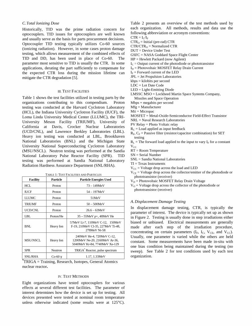
Figure 9: 55MeV Proton Induced CTR Degradation in TI 4N49 (SN4).
The 4N49 was irradiated with 55MeV protons and 48MeVHelium ions at LBL. The parts were irradiated under bias andtested after each step. Test parameters were set at IF = 2mA,VCC = 5V, VCE = 5V. CTR degradation was noted in bothcases. See Figures 10 and 11.
0
0.2
0.4
0.6
0.8
1
1.2
0 20 40 60 80 100 120 140
TID [krads(Si)]
CT
R/C
TR
o
Figure 10: 55MeV Proton Induced CTR Degradation in TI 4N49.
0
0.2
0.4
0.6
0.8
1
1.2
0 2 4 6 8 10 12 14 16
TID [krads(Si)]
CT
R/C
TR
o
Figure 11: 48MeV Helium Induced CTR Degradation in TI 4N49.
c. OLF400 (Isolink)The OLF400 was irradiated with 55MeV protons at LBL.Test parameters were set at VCC = 5V, VCE = 5V and theoutput resistance was 300Ω. The input resistance was varied(RL = 8kΩ, 10kΩ, 16kΩ, 20kΩ, 30kΩ, and 40kΩ) to give IF
= 0.429mA, 0.344mA, 0.216mA, 0.173mA, 0.166mA, and0.087mA respectively. Output current was measured at eachstep for each of the resistors. The results show a decrease inoutput current with increasing proton dose, that is, CTRdegradation. Results are presented in Figure 12.
0
2
4
6
8
10
12
14
16
18
0 0.1 0.2 0.3 0.4 0.5
Input Current IF (mA)
Out
put C
urre
nt I
C (m
A)
Pre-rad 20krads 40krads 60krads 80krads 100krads 120krads
Figure 12: 55MeV Proton Induced IC Degradation in Isolink OLF400.
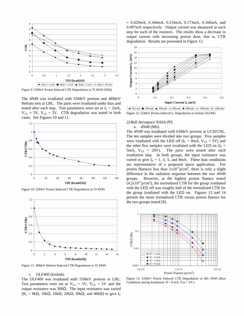
2) Ball Aerospace NASA/JPLa. 4N49 (Mii)
The 4N49 was irradiated with 63MeV protons at UCD/CNL.The ten samples were divided into two groups. Five sampleswere irradiated with the LED off (IF = 0mA, VCE = 5V) andthe other five samples were irradiated with the LED on (IF =5mA, VCE = 28V). The parts were tested after eachirradiation step. In both groups, the input resistance wasvaried to give IF = 1, 3, 5, and 8mA. These bias conditionsare representative of a proposed space application. Forproton fluences less than 1x10¹¹p/cm2, there is only a slightdifference in the radiation response between the two 4N49groups. However, at the highest proton fluence tested(4.2x10¹¹p/cm2), the normalized CTR for the group irradiatedwith the LED off was roughly half of the normalized CTR forthe group irradiated with the LED on. Figures 13 and 14present the mean normalized CTR versus proton fluence forthe two groups tested [8].
0.001
0.01
0.1
1
1.E+10 1.E+11 1.E+12Proton Fluence (p/cm2)
CTR
/CTR
o
If = 1 mAIf = 3 mAIf = 5 mAIf = 8 mA
Figure 13: 63MeV Proton Induced CTR Degradation in Mii 4N49 (BiasConditions during Irradiation: If = 0 mA, Vce = 5V.)
0.001
0.01
0.1
1
1.E+10 1.E+11 1.E+12Proton Fluence (p/cm2)
CTR
/CTR
o
If = 1 mAIf = 3 mAIf = 5 mAIf = 8 mA
Figure 14: 63MeV Proton Induced CTR Degradation in Mii 4N49 (BiasConditions during Irradiation: If = 5 mA, Vce = 28V.)
b. OMT1062 (Optek)The OMT1062 slotted optical switch was irradiated with63MeV protons at UCD/CNL. Six samples were stepirradiated with the LED biased on (IF = 15mA, VCE = 5V)which reflects the particular application of interest. The partswere tested after each step irradiation. The input resistancewas varied to produce IF = 5, 10, 15, and 20mA. The meannormalized CTR is plotted versus proton fluence in Figure 15.Other test samples from this date code were previouslyevaluated for TID from gamma rays and those test results forIF = 10mA have been included. Note that 7.4x10⁹p/cm2
(63MeV protons) imparts a total ionizing dose of~1.0krad(Si). This data suggests that ionizing dose damageconstitutes about 2% of the combined ionizing dose anddisplacement damage (at 2.2x10¹¹p/cm2) [8].
0.001
0.01
0.1
1
1.E+10 1.E+11 1.E+12
Proton Fluence (p/cm2)
CTR
/CTR
o
If = 5 mAIf = 10 mAIf = 15 mAIf = 20 mAGamma Test, If=10mA
Figure 15: 63MeV Proton Induced CTR Degradation in Optek OMT1062(Bias Conditions during Irradiation: If = 15 mA, Vce = 10V.)
3) Boeinga. 66092 (Mii)
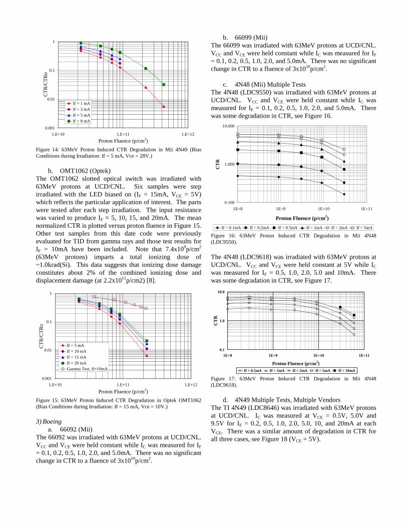
The 66092 was irradiated with 63MeV protons at UCD/CNL.VCC and VCE were held constant while IC was measured for IF= 0.1, 0.2, 0.5, 1.0, 2.0, and 5.0mA. There was no significantchange in CTR to a fluence of 3x10¹⁰p/cm2.
b. 66099 (Mii)The 66099 was irradiated with 63MeV protons at UCD/CNL.VCC and VCE were held constant while IC was measured for IF= 0.1, 0.2, 0.5, 1.0, 2.0, and 5.0mA. There was no significantchange in CTR to a fluence of 3x10¹⁰p/cm2.
c. 4N48 (Mii) Multiple TestsThe 4N48 (LDC9550) was irradiated with 63MeV protons atUCD/CNL. VCC and VCE were held constant while IC wasmeasured for IF = 0.1, 0.2, 0.5, 1.0, 2.0, and 5.0mA. Therewas some degradation in CTR, see Figure 16.
0.100
1.000
10.000
1E+8 1E+9 1E+10 1E+11
Proton Fluence (p/cm2)C
TR
If = 0.1mA If = 0.2mA If = 0.5mA If = 1mA If = 2mA If = 5mA
Figure 16: 63MeV Proton Induced CTR Degradation in Mii 4N48(LDC9550).
The 4N48 (LDC9618) was irradiated with 63MeV protons atUCD/CNL. VCC and VCE were held constant at 5V while ICwas measured for IF = 0.5, 1.0, 2.0, 5.0 and 10mA. Therewas some degradation in CTR, see Figure 17.
0.1
1.0
10.0
1E+8 1E+9 1E+10 1E+11
Proton Fluence (p/cm2)
CT
R
If = 0.5mA If = 1mA If = 2mA If = 5mA If = 10mA
Figure 17: 63MeV Proton Induced CTR Degradation in Mii 4N48(LDC9618).
d. 4N49 Multiple Tests, Multiple VendorsThe TI 4N49 (LDC8646) was irradiated with 63MeV protonsat UCD/CNL. IC was measured at VCE = 0.5V, 5.0V and9.5V for IF = 0.2, 0.5, 1.0, 2.0, 5.0, 10, and 20mA at eachVCE. There was a similar amount of degradation in CTR forall three cases, see Figure 18 (VCE = 5V).
0.1
1.0
10.0
0.0E+0 5.0E+9 1.0E+10 1.5E+10 2.0E+10 2.5E+10 3.0E+10 3.5E+10
Proton Fluence (p/cm2)
CT
R
If 0.2mA 0.5mA 1mA 2mA 5mA 10mA 10mA
Figure 18: 63MeV Proton Induced CTR Degradation in Mii 4N49(LDC8646).
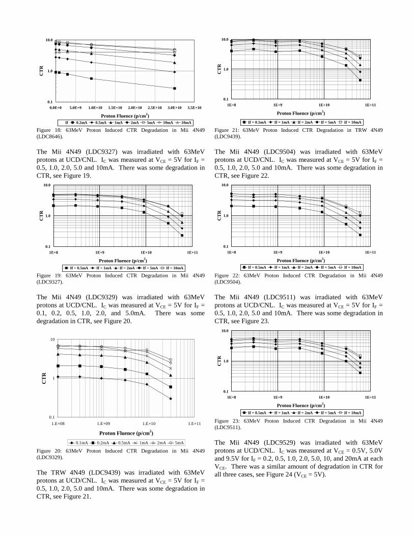
The Mii 4N49 (LDC9327) was irradiated with 63MeVprotons at UCD/CNL. IC was measured at VCE = 5V for IF =0.5, 1.0, 2.0, 5.0 and 10mA. There was some degradation inCTR, see Figure 19.
0.1
1.0
10.0
1E+8 1E+9 1E+10 1E+11
Proton Fluence (p/cm2)
CT
R
If = 0.5mA If = 1mA If = 2mA If = 5mA If = 10mA
Figure 19: 63MeV Proton Induced CTR Degradation in Mii 4N49(LDC9327).
The Mii 4N49 (LDC9329) was irradiated with 63MeVprotons at UCD/CNL. IC was measured at VCE = 5V for IF =0.1, 0.2, 0.5, 1.0, 2.0, and 5.0mA. There was somedegradation in CTR, see Figure 20.
0.1
1
10
1.E+08 1.E+09 1.E+10 1.E+11
Proton Fluence (p/cm2)
CT
R
0.1mA 0.2mA 0.5mA 1mA 2mA 5mA
Figure 20: 63MeV Proton Induced CTR Degradation in Mii 4N49(LDC9329).
The TRW 4N49 (LDC9439) was irradiated with 63MeVprotons at UCD/CNL. IC was measured at VCE = 5V for IF =0.5, 1.0, 2.0, 5.0 and 10mA. There was some degradation inCTR, see Figure 21.
0.1
1.0
10.0
1E+8 1E+9 1E+10 1E+11
Proton Fluence (p/cm2)
CT
R
If = 0.5mA If = 1mA If = 2mA If = 5mA If = 10mA
Figure 21: 63MeV Proton Induced CTR Degradation in TRW 4N49(LDC9439).
The Mii 4N49 (LDC9504) was irradiated with 63MeVprotons at UCD/CNL. IC was measured at VCE = 5V for IF =0.5, 1.0, 2.0, 5.0 and 10mA. There was some degradation inCTR, see Figure 22.
0.1
1.0
10.0
1E+8 1E+9 1E+10 1E+11
Proton Fluence (p/cm2)
CT
R
If = 0.5mA If = 1mA If = 2mA If = 5mA If = 10mA
Figure 22: 63MeV Proton Induced CTR Degradation in Mii 4N49(LDC9504).
The Mii 4N49 (LDC9511) was irradiated with 63MeVprotons at UCD/CNL. IC was measured at VCE = 5V for IF =0.5, 1.0, 2.0, 5.0 and 10mA. There was some degradation inCTR, see Figure 23.
0.1
1.0
10.0
1E+8 1E+9 1E+10 1E+11
Proton Fluence (p/cm2)
CT
R
If = 0.5mA If = 1mA If = 2mA If = 5mA If = 10mA
Figure 23: 63MeV Proton Induced CTR Degradation in Mii 4N49(LDC9511).
The Mii 4N49 (LDC9529) was irradiated with 63MeVprotons at UCD/CNL. IC was measured at VCE = 0.5V, 5.0Vand 9.5V for IF = 0.2, 0.5, 1.0, 2.0, 5.0, 10, and 20mA at eachVCE. There was a similar amount of degradation in CTR forall three cases, see Figure 24 (VCE = 5V).
0.1
1
10
1.E+08 1.E+09 1.E+10 1.E+11
Proton Fluence (p/cm2)
CT
R
If = 0.1mA If = 0.2mA If = 0.5mA If = 1mA If = 2mA If = 5mA
Figure 24: 63MeV Proton Induced CTR Degradation in Mii 4N49(LDC9529).
The Mii 4N49 (LDC9550) was irradiated with 63MeVprotons at UCD/CNL. IC was measured at VCE = 5V for IF =0.1, 0.2, 0.5, 1.0, 2.0, and 5.0mA. There was somedegradation in CTR, see Figure 25.
0.1
1
10
1.E+08 1.E+09 1.E+10 1.E+11
Proton Fluence (p/cm2)
CT
R
0.1mA 0.2mA 0.5mA 1mA 2mA 5mA
Figure 25: 63MeV Proton Induced CTR Degradation in Mii 4N49(LDC9550).
The Mii 4N49 (LDC9623) was irradiated with 63MeVprotons at UCD/CNL. IC was measured at VCE = 5V for IF =0.1, 0.2, 0.5, 1.0, 2.0, 5.0, 10 and 20mA. There was somedegradation in CTR, see Figure 26.
0.1
1
10
1E+8 1E+9 1E+10 1E+11
Proton Fluence (p/cm2)
CT
R
If = 0.1mA If = 0.2mA If = 0.5mA If = 1mAIf = 2mA If = 5mA If = 10mA If = 20mA
Figure 26: 63MeV Proton Induced CTR Degradation in Mii 4N49(LDC9623).
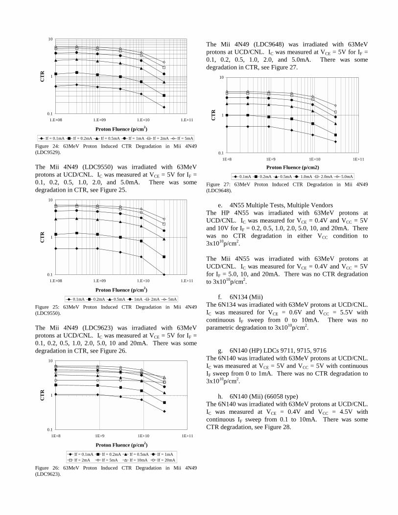
The Mii 4N49 (LDC9648) was irradiated with 63MeVprotons at UCD/CNL. IC was measured at VCE = 5V for IF =0.1, 0.2, 0.5, 1.0, 2.0, and 5.0mA. There was somedegradation in CTR, see Figure 27.
0.1
1
10
1E+8 1E+9 1E+10 1E+11
Proton Fluence (p/cm2)
CT
R
0.1mA 0.2mA 0.5mA 1.0mA 2.0mA 5.0mA
Figure 27: 63MeV Proton Induced CTR Degradation in Mii 4N49(LDC9648).
e. 4N55 Multiple Tests, Multiple VendorsThe HP 4N55 was irradiated with 63MeV protons atUCD/CNL. IC was measured for VCE = 0.4V and VCC = 5Vand 10V for IF = 0.2, 0.5, 1.0, 2.0, 5.0, 10, and 20mA. Therewas no CTR degradation in either VCC condition to3x1010p/cm2.
The Mii 4N55 was irradiated with 63MeV protons atUCD/CNL. IC was measured for VCE = 0.4V and VCC = 5Vfor IF = 5.0, 10, and 20mA. There was no CTR degradationto 3x10¹⁰p/cm2.
f. 6N134 (Mii)The 6N134 was irradiated with 63MeV protons at UCD/CNL.IC was measured for VCE = 0.6V and VCC = 5.5V withcontinuous IF sweep from 0 to 10mA. There was noparametric degradation to 3x10¹⁰p/cm2.
g. 6N140 (HP) LDCs 9711, 9715, 9716The 6N140 was irradiated with 63MeV protons at UCD/CNL.IC was measured at VCE = 5V and VCC = 5V with continuousIF sweep from 0 to 1mA. There was no CTR degradation to3x1010p/cm2.
h. 6N140 (Mii) (66058 type)The 6N140 was irradiated with 63MeV protons at UCD/CNL.IC was measured at VCE = 0.4V and VCC = 4.5V withcontinuous IF sweep from 0.1 to 10mA. There was someCTR degradation, see Figure 28.
0.1
1.0
10.0
100.0
1E-4 1E-3 1E-2If (A)
CT
R
Typ_CTR Init_CTR CTR @9E8CTR @3E9 CTR @9E9 CTR @3E10
Proton Fluence (p/cm2)
Figure 28: 63MeV Proton Induced CTR Degradation in 6N140 (LDC9623).
i. DIH126 (Dionics)The DIH126 PV Relay was irradiated with 63MeV protons atUCD/CNL. There was relay degradation in both the forwardand reverse directions and for VD = 5V and 100V. Thedegradation of VD was very similar to that of the degradationof ID in both the forward and reverse directions as seen inFigure 29.
-0.01
0.00
0.01
0.02
0.03
0.04
0.05
0.06
0.0E+0 1.0E-3 2.0E-3 3.0E-3 4.0E-3 5.0E-3
If (A)
Id (A
)
-0.04
-0.03
-0.02
-0.01
0.00
0.01
0.02
0.03Id
(A)
0E+0 9E+8 3E+9 9E+9 3E+10
Reverse Dir(Use scale ! )
Forward Dir(" Use scale)
Proton Fluence (p/cm2)
Figure 29: 63MeV Proton Induced Forward/Reverse Relay DegradationMeasurements for DIH126.
j. FB00KBY (Teledyne)The FB00KBY PV Relay was irradiated with 63MeV protonsat UCD/CNL. There was relay degradation in both theforward and reverse directions and for VD = 5V and 100V.The degradation of VD was very similar to that of thedegradation of ID in both the forward and reverse directionsas seen in Figure 30.
-0.01
0.00
0.01
0.02
0.03
0.04
0.05
0.06
0.0E+0 5.0E-4 1.0E-3 1.5E-3 2.0E-3 2.5E-3 3.0E-3 3.5E-3 4.0E-3 4.5E-3 5.0E-3
If (A)
Id (A
)
-0.04
-0.03
-0.02
-0.01
0.00
0.01
0.02
0.03
Id (A
)
0E+0 9E+8 3E+9 9E+9 3E+10
Reverse Dir(Use scale ! )
Forward Dir(" Use scale)
Proton Fluence (p/cm2)
Figure 30: 63MeV Proton Induced Relay Degradation in FB00KBY.
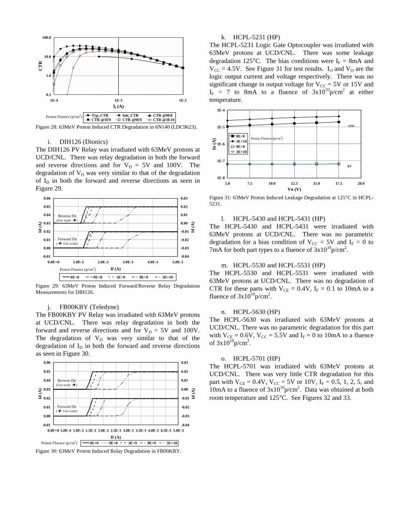
k. HCPL-5231 (HP)The HCPL-5231 Logic Gate Optocoupler was irradiated with63MeV protons at UCD/CNL. There was some leakagedegradation 125°C. The bias conditions were IF = 8mA andVCC = 4.5V. See Figure 31 for test results. IO and VO are thelogic output current and voltage respectively. There was nosignificant change in output voltage for VCC = 5V or 15V andIF = 7 to 8mA to a fluence of 3x10¹⁰p/cm2 at eithertemperature.
1E-8
1E-7
1E-6
1E-5
1E-4
5.0 7.5 10.0 12.5 15.0 17.5 20.0Vo (V)
Io (A
) 0E+03E+100E+03E+10
125C
RT
Proton Fluence (p/cm2)
Figure 31: 63MeV Proton Induced Leakage Degradation at 125°C in HCPL-5231.
l. HCPL-5430 and HCPL-5431 (HP)The HCPL-5430 and HCPL-5431 were irradiated with63MeV protons at UCD/CNL. There was no parametricdegradation for a bias condition of VCC = 5V and IF = 0 to7mA for both part types to a fluence of 3x10¹⁰p/cm2.
m. HCPL-5530 and HCPL-5531 (HP)The HCPL-5530 and HCPL-5531 were irradiated with63MeV protons at UCD/CNL. There was no degradation ofCTR for these parts with VCE = 0.4V, IF = 0.1 to 10mA to afluence of 3x10¹⁰p/cm2.
n. HCPL-5630 (HP)The HCPL-5630 was irradiated with 63MeV protons atUCD/CNL. There was no parametric degradation for this partwith VCE = 0.6V, VCC = 5.5V and IF = 0 to 10mA to a fluenceof 3x10¹⁰p/cm2.
o. HCPL-5701 (HP)The HCPL-5701 was irradiated with 63MeV protons atUCD/CNL. There was very little CTR degradation for thispart with VCE = 0.4V, VCC = 5V or 10V, IF = 0.5, 1, 2, 5, and10mA to a fluence of 3x10¹⁰p/cm2. Data was obtained at bothroom temperature and 125°C. See Figures 32 and 33.

0
2
4
6
8
10
12
14
16
18
1.E+08 1.E+09 1.E+10 1.E+11
Proton Fluence (p/cm2)
CT
RIf at 125C0.5mA1mA2mA5mA10mAIf at RT0.5mA1mA2mA5mA10mA
Figure 32: 63MeV Proton Induced CTR Degradation in HCPL-5701 atRoom Temperature and 125°C for VCC = 5V.
0
2
4
6
8
10
12
14
16
18
1.E+08 1.E+09 1.E+10 1.E+11
Proton Fluence (p/cm2)
CT
R
If at 125C0.5mA1mA2mA5mA10mAIf at RT0.5mA1mA2mA5mA10mA
Figure 33: 63MeV Proton Induced CTR Degradation in HCPL-5701 atRoom Temperature and 125°C for VCC = 10V.
p. HCPL-5730 (HP)The HCPL-5730 was irradiated with 63MeV protons atUCD/CNL. There was no CTR degradation for this part withVCE = 0.4V, VCC = 5V, IF = 0.5, 1, 2, 5, and 10mA to afluence of 3x10¹⁰p/cm2. Data was obtained at both roomtemperature and 125°C. See Figure 34.
0
2
4
6
8
10
12
14
16
18
1.E+08 1.E+09 1.E+10 1.E+11
Proton Fluence (p/cm2)
CT
R
If at 125C0.5mA1mA2mA5mA10mAIf at RT0.5mA1mA2mA5mA10mA
Figure 34: 63MeV Proton Induced CTR Degradation in HCPL-5730.
q. OLH149, OLH249, OLH304, and OLH349 (Isolink)These Isolink parts were irradiated with 63MeV protons atUCD/CNL. There was no significant degradation in CTR for
any of the parts irradiated. The bias conditions were VCC =5V and IF = 0.5, 1, 2, and 5mA. The parts were irradiated toa fluence of 3x10¹⁰p/cm2.
r. OLH400 (Isolink)The OLH400 was irradiated with 63MeV protons atUCD/CNL. There was no CTR degradation for this part withIF = 1, 2, 5, 10, and 20mA to a fluence of 3x10¹⁰p/cm2 at bothroom temperature and 125°C.
4) Goddard Space Flight Center, NASAa. 66088 (Mii) Multiple Tests
The 66088 was irradiated at UCD/CNL with 63MeV protons.CTR degradation measurements were taken for IF = 10, 15and 20mA, VCE = 5V. No degradation of CTR was observedto 1x10⁹p/cm2 [6].
The 66088 was irradiated at UCD/CNL with 63MeV protons.The tests conditions were IF = 4.1, 10, 15.4, and 19.7mA withconstant VCE = 5V [9]. See Figure 35.
0
0.05
0.1
0.15
0.2
0.25
0.3
0.35
0.4
0.45
0.5
0.E+00 2.E+10 4.E+10 6.E+10 8.E+10 1.E+11
Proton Fluence (p/cm2)
CT
R
If = 4.1mA If = 10mA If = 15.4mA If = 19.7mA
Figure 35: 63MeV Proton Induced CTR Degradation in 66088.
b. 66099 (Mii) Multiple TestsValidation of an optocoupler spaceflight experiment that is tobe flown on STRV-1d was done at TRIUMF using 58MeVprotons with a minimum fluence of 2x10¹⁰p/cm2. Mii’s 66099was tested and showed no CTR degradation [6].
The 66099 was irradiated with 63MeV protons at UCD/CNL.There was significant CTR degradation with VCE = 5V, IF =1mA and 5mA into a load of 0 or 1kΩ. See Figure 36.
0.001
0.01
0.1
1
10
0.E+00 1.E+12 2.E+12 3.E+12 4.E+12 5.E+12
Proton Fluence (p/cm2)
CTR
Load = 0 kohm, If = 1mALoad = 1 kohm, If = 1mALoad = 0 kohm, If = 5mALoad = 1 kohm, If = 5mA
Figure 36: 63MeV Proton Induced CTR Degradation in 66099.

c. 66123 (Mii)Validation of an optocoupler spaceflight experiment that is tobe flown on STRV-1d was done at TRIUMF using 58MeVprotons with a minimum fluence of 2x10¹⁰p/cm2. Mii’s 66123was tested and showed no parametric degradation [6].
d. 3C91C (Mitel)Several 3C91C devices were irradiated at UCD/CNL with 63,31, 21, and 14MeV protons. The Mitel 3C91C contains anamphoterically doped LED. Figure 37 shows in-situmeasurements made during irradiation with 63 and 31MeVprotons. The test parameters were IF = 5mA and Vce = 5V.As expected, 31MeV protons induce more degradation than63MeV protons for an equivalent fluence. Results from the21 and 14MeV protons are similar to the results for the31MeV protons. Significant part-to-part variability was alsoobserved (See Figure 38). Annealing measurements were notmade [9].
0
0.2
0.4
0.6
0.8
1
1.2
0.E+00 2.E+10 4.E+10 6.E+10 8.E+10 1.E+11
Proton Fluence (p/cm2)
CT
R
DUT #1 DUT #11 DUT #23 DUT #20 DUT #29 DUT #49
63MeV
31MeV
Figure 37: 63 and 31MeV Proton Induced CTR Degradation in 3C91C.
0.00
0.20
0.40
0.60
0.80
1.00
1.20
0.E+00 2.E+10 4.E+10 6.E+10 8.E+10 1.E+11
Fluence (32MeV protons/cm2)
CTR
/CT
Ro
#20 initial CTR=98#29 initial CTR=81#49 initial CTR=54
Mitel 3C91C (device is made with no coupling medium)IF = 5mA, VCE = 5V
Figure 38: Part to Part Variability in CTR Degradation in 3C91C.
e. 4N48 Multiple Tests, Multiple VendorsThe Mii 4N48 was irradiated with neutrons at SPR. Theaverage CTR after each step irradiation is shown in Figure 5for IF varying from 1.65 to 6.2mA. Degradation occurredonly at the lowest drive currents for this application. Alldevices had degraded to <1% CTR after an exposure with1MeV-equivalent neutrons of 6x10¹²n/cm2 [6,12].
0
2
4
6
8
10
12
14
16
0.E+00 2.E+11 4.E+11 6.E+11 8.E+11 1.E+12
Fluence (neutrons/cm2)
CT
R
If = 1.6mA If = 2.4mA If = 2.9mA If = 3.5mAIf = 4.3mA If = 5.1mA If = 6.2mA
Figure 39: 1 MeV Equivalent Neutron Induced CTR Degradation in Mii4N48.
The Optek 4N48 was irradiated at UCD/CNL with 63MeVprotons. The Optek 4N48 contains an amphoterically dopedLED. Figure 40 gives in-situ measurements of CTR. IF variedbetween 1.4 and 20.8mA with initial CTR peaking between1.4 and 3mA. For this application, the collector current wassaturated for drive currents greater than 2.5mA. Operating adevice in this mode leads to a more radiation tolerantapplication [9]. See Figure 40.
0
0.2
0.4
0.6
0.8
1
1.2
1.4
1.6
1.8
2
0.E+00 2.E+10 4.E+10 6.E+10 8.E+10 1.E+11
Proton Fluence (p/cm2)
CT
R
If = 20.8mA If = 5.2mA If = 3.0mA If = 2.5mA If = 1.4mA
Figure 40: 63MeV Proton Induced CTR Degradation in Optec 4N48.
f. 4N49 Multiple Tests, Multiple VendorsValidation of an optocoupler spaceflight experiment that is tobe flown on STRV-1d was done at TRIUMF using 58MeVprotons with a minimum fluence of 2x10²p/cm2. Mii’s 4N49was irradiated and there was no CTR degradation [6].
The TI 4N49 was irradiated at UCD/CNL with 63MeVprotons. Figure 41 gives in situ measurements of CTR. IFwas varied between 1.2 and 11mA and VCE = 6V [6].
00.10.20.30.40.50.60.70.80.9
1
0.E+00 1.E+11 2.E+11 3.E+11 4.E+11 5.E+11 6.E+11
Proton Fluence (p/cm2)
CT
R/C
TR
o
If = 11mA If = 8mA If = 4.1mA If = 3.1mAIf = 2.1mA If = 1.15mA
Figure 41: 63MeV Proton Induced CTR Degradation in TI 4N49.
g. 6N134 (HP)The 6N134 was irradiated with neutrons at SPR. Eightdevices were tested to a 1MeV-equivalent fluence of8x1011n/cm2. IF was varied from 4 to 26mA with VCE = 5V.No parametric degradation was observed [12].
h. 6N140 (Mii)Validation of an optocoupler spaceflight experiment that is tobe flown on STRV-1d was done at TRIUMF using 58MeVprotons with a minimum fluence of 2x10¹⁰p/cm2. Mii’s 6N140was tested and there was no CTR degradation [6].
i. HCPL-6651 (HP)Validation of an optocoupler spaceflight experiment that is tobe flown on STRV-1d was done at TRIUMF using 58MeVprotons with a minimum fluence of 2x10¹⁰p/cm2. HP’s HCPL-6651 was tested and there was no parametric degradation [6].
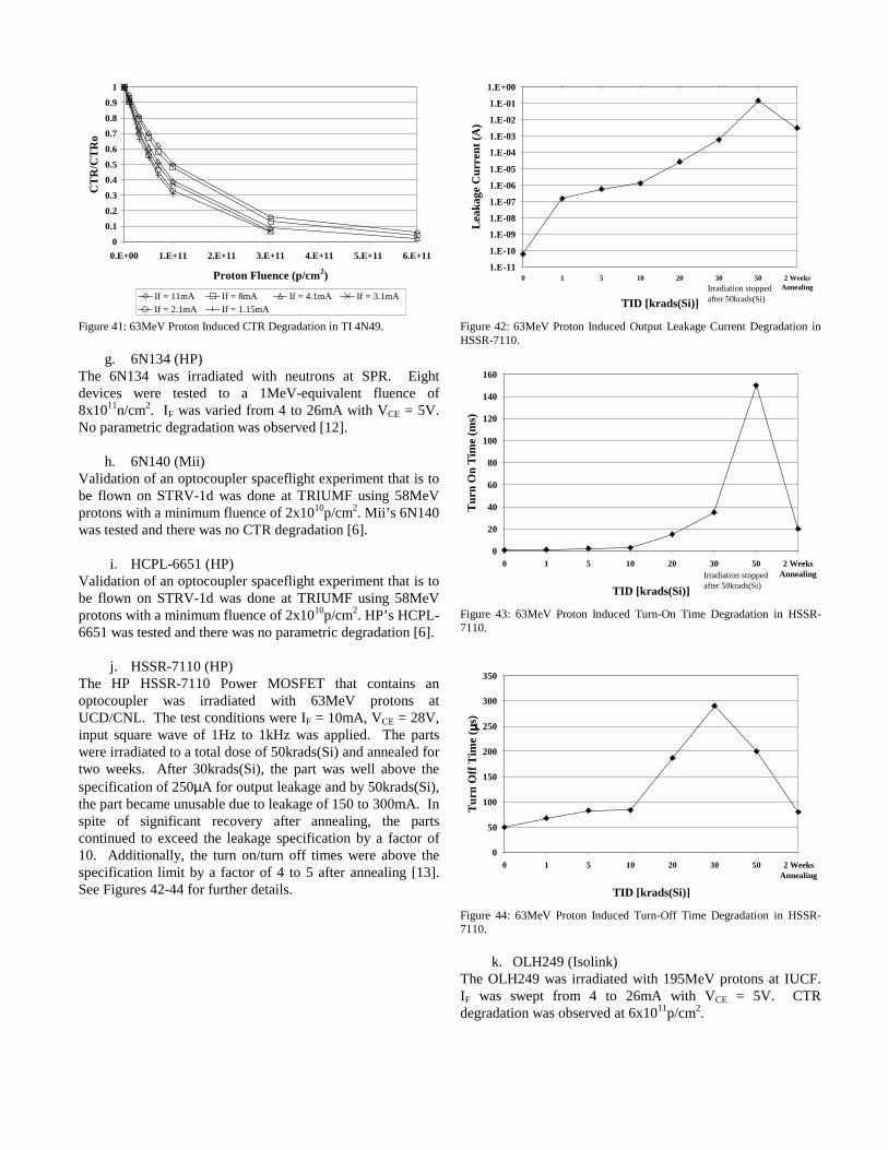
j. HSSR-7110 (HP)The HP HSSR-7110 Power MOSFET that contains anoptocoupler was irradiated with 63MeV protons atUCD/CNL. The test conditions were IF = 10mA, VCE = 28V,input square wave of 1Hz to 1kHz was applied. The partswere irradiated to a total dose of 50krads(Si) and annealed fortwo weeks. After 30krads(Si), the part was well above thespecification of 250µA for output leakage and by 50krads(Si),the part became unusable due to leakage of 150 to 300mA. Inspite of significant recovery after annealing, the partscontinued to exceed the leakage specification by a factor of10. Additionally, the turn on/turn off times were above thespecification limit by a factor of 4 to 5 after annealing [13].See Figures 42-44 for further details.
1.E-11
1.E-10
1.E-09
1.E-08
1.E-07
1.E-06
1.E-05
1.E-04
1.E-03
1.E-02
1.E-01
1.E+00
0 1 5 10 20 30 50 2 WeeksAnnealing
TID [krads(Si)]
Lea
kage
Cur
rent
(A)
Irradiation stopped after 50krads(Si)
Figure 42: 63MeV Proton Induced Output Leakage Current Degradation inHSSR-7110.
0
20
40
60
80
100
120
140
160
0 1 5 10 20 30 50 2 WeeksAnnealing
TID [krads(Si)]
Turn
On
Tim
e (m
s)
Irradiation stopped after 50krads(Si)
Figure 43: 63MeV Proton Induced Turn-On Time Degradation in HSSR-7110.
0
50
100
150
200
250
300
350
0 1 5 10 20 30 50 2 WeeksAnnealing
TID [krads(Si)]
Tur
n O
ff T
ime
( µ µµµs)
Figure 44: 63MeV Proton Induced Turn-Off Time Degradation in HSSR-7110.
k. OLH249 (Isolink)The OLH249 was irradiated with 195MeV protons at IUCF.IF was swept from 4 to 26mA with VCE = 5V. CTRdegradation was observed at 6x10¹¹p/cm2.
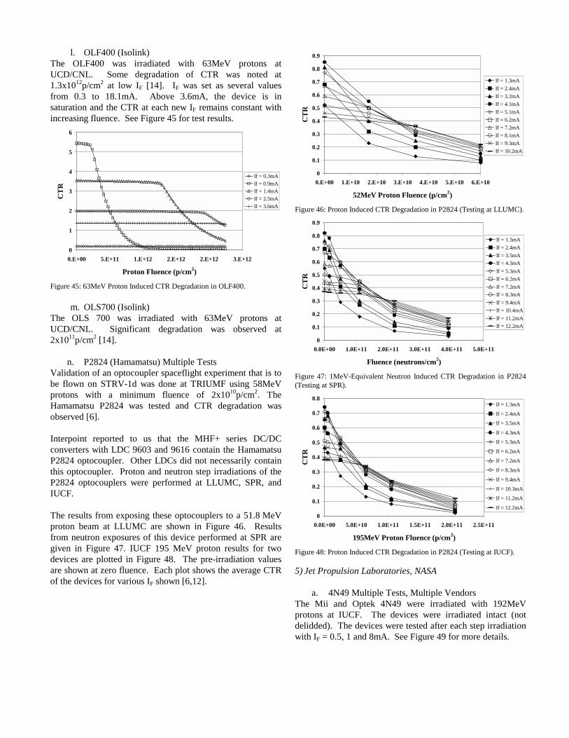
l. OLF400 (Isolink)The OLF400 was irradiated with 63MeV protons atUCD/CNL. Some degradation of CTR was noted at1.3x1012p/cm2 at low IF [14]. IF was set as several valuesfrom 0.3 to 18.1mA. Above 3.6mA, the device is insaturation and the CTR at each new IF remains constant withincreasing fluence. See Figure 45 for test results.
0
1
2
3
4
5
6
0.E+00 5.E+11 1.E+12 2.E+12 2.E+12 3.E+12
Proton Fluence (p/cm2)
CT
R
If = 0.3mAIf = 0.9mAIf = 1.4mAIf = 2.5mAIf = 3.6mA
Figure 45: 63MeV Proton Induced CTR Degradation in OLF400.
m. OLS700 (Isolink)The OLS 700 was irradiated with 63MeV protons atUCD/CNL. Significant degradation was observed at2x1011p/cm2 [14].
n. P2824 (Hamamatsu) Multiple TestsValidation of an optocoupler spaceflight experiment that is tobe flown on STRV-1d was done at TRIUMF using 58MeVprotons with a minimum fluence of 2x10¹⁰p/cm2. TheHamamatsu P2824 was tested and CTR degradation wasobserved [6].
Interpoint reported to us that the MHF+ series DC/DCconverters with LDC 9603 and 9616 contain the HamamatsuP2824 optocoupler. Other LDCs did not necessarily containthis optocoupler. Proton and neutron step irradiations of theP2824 optocouplers were performed at LLUMC, SPR, andIUCF.
The results from exposing these optocouplers to a 51.8 MeVproton beam at LLUMC are shown in Figure 46. Resultsfrom neutron exposures of this device performed at SPR aregiven in Figure 47. IUCF 195 MeV proton results for twodevices are plotted in Figure 48. The pre-irradiation valuesare shown at zero fluence. Each plot shows the average CTRof the devices for various IF shown [6,12].
0
0.1
0.2
0.3
0.4
0.5
0.6
0.7
0.8
0.9
0.E+00 1.E+10 2.E+10 3.E+10 4.E+10 5.E+10 6.E+10
52MeV Proton Fluence (p/cm2)
CT
R
If = 1.3mAIf = 2.4mAIf = 3.2mAIf = 4.1mAIf = 5.1mAIf = 6.2mAIf = 7.2mAIf = 8.1mAIf = 9.3mAIf = 10.2mA
Figure 46: Proton Induced CTR Degradation in P2824 (Testing at LLUMC).
0
0.1
0.2
0.3
0.4
0.5
0.6
0.7
0.8
0.9
0.0E+00 1.0E+11 2.0E+11 3.0E+11 4.0E+11 5.0E+11
Fluence (neutrons/cm2)
CT
R
If = 1.3mAIf = 2.4mAIf = 3.5mAIf = 4.3mAIf = 5.3mAIf = 6.2mAIf = 7.2mAIf = 8.3mAIf = 9.4mAIf = 10.4mAIf = 11.2mAIf = 12.2mA
Figure 47: 1MeV-Equivalent Neutron Induced CTR Degradation in P2824(Testing at SPR).
0
0.1
0.2
0.3
0.4
0.5
0.6
0.7
0.8
0.0E+00 5.0E+10 1.0E+11 1.5E+11 2.0E+11 2.5E+11
195MeV Proton Fluence (p/cm2)
CT
R
If = 1.3mA
If = 2.4mA
If = 3.5mA
If = 4.3mA
If = 5.3mA
If = 6.2mA
If = 7.2mA
If = 8.3mA
If = 9.4mA
If = 10.3mA
If = 11.2mA
If = 12.2mA
Figure 48: Proton Induced CTR Degradation in P2824 (Testing at IUCF).
5) Jet Propulsion Laboratories, NASA
a. 4N49 Multiple Tests, Multiple VendorsThe Mii and Optek 4N49 were irradiated with 192MeVprotons at IUCF. The devices were irradiated intact (notdelidded). The devices were tested after each step irradiationwith IF = 0.5, 1 and 8mA. See Figure 49 for more details.
0.001
0.01
0.1
1
0 1E+11 2E+11 3E+11 4E+11 5E+11 6E+11 7E+11
Proton Fluence (p/cm2)
CTR
/CTR
o
Micropac
Optek
Micropac
Optek
If = 8 mA
Solid line:IF=1mA,DashedLine: IF=0.5mA
Figure 49: 192MeV Proton Induced CTR Degradation in Mii and Optek4N49.
b. OLH1049 (Optek) Multiple TestsThree different device styles of the Optek OLH1049 wereirradiated with 50MeV protons at UCD/CNL. The parts wereirradiated with three different bias conditions: (1) IF = 0V andVCE = 5V, (2) IF = 0.5mA, VCE = 0V, and (3) IF = 3mA, VCE =0V. Electrical measurements were made with VCE = 5V andIF = 0.1, 0.2, 0.5, and 1mA. The parts showed some CTRdegradation beginning at 1x10¹⁰p/cm2 and end results at8x1010p/cm2 were slightly more than an order of magnitudeless than initial values. It is interesting to note that diagnostictests revealed that displacement damage in the LED is thedominant mechanism, rather than displacement damage in thephotodiode.
6) Lockheed Martin Space System Company, Missiles &Space Operations
a. 4N35, 4N49, 6N140 (Mii)The Mii 4N35, 4N49 and 6N140 optocouplers were irradiatedwith 192MeV protons at IUCF. CTR degradation wasnoticeable in these Mii devices with IF = 1mA and VCC = 5Vat 1x10¹¹p/cm2 as shown in Figure 50. A special process Mii4N35 was tested that showed improvement in the hardnessagainst CTR degradation.
b. HCPL-2201, HCPL-2430 (HP)HP HCPL-2201 and HCPL-2430 optocouplers wereirradiated with 192MeV protons at IUCF. Test conditionswere IF = 1mA and VCC = 5V. These devices did not showany noticeable CTR degradation up to 6x10¹¹p/cm2. Also seeFigure 50.
109 1010 1011 10120.01
0.1
1
10
100
HCPL 2430 HCPL-2201 4N35 S/N 1 4N49 JANTX S/N 1 4N49 Special S/N 1 6N140 S/N 1
CTR
Proton Fluence (p/cm2)Figure 50: 192MeV Proton Induced CTR Degradation in Mii 4N35, 4N49,6N140 and HP HCPL 2430, HCPL 2201 optocouplers.
c. 81082-300 photodiode (Mii)The Mii 81082 photodiode was irradiated with 73MeVprotons at HCL. The photodiode showed degradation withincreasing fluence. (Pre irradiation IC = 3.0µA, 2x10¹⁰p/cm2 =2.1µA, 1.2x10¹¹p/cm2 = 0.6µA, 4.2x10¹¹p/cm2 = 0.2µA.)
d. 62017 (GS3040-3 LED) (Mii)The Mii 62017 (GS3040-3 LED) was irradiated with 73MeVprotons at HCL. The LED showed little change withincreasing fluence. (Pre irradiation IF = 15 mA, 2x10¹⁰p/cm2
= 15.4 mA, 1.2x10¹¹p/cm2 = 15.3 mA, 4.2x10¹¹p/cm2 = 15.07mA, (0.90 mW output at If = 50 mA))
e. OP224 LED/OP604 phototransistor (Optek)The Optek OP224 GaAlAs LED and OP604 phototransistorwere irradiated with 73MeV protons at HCL. Displacementdamage was observed in the OP604 with VCE = 15V at afluence of 2x10¹⁰p/cm2. See Figures 51 and 52.
Figure 51: Proton Damage observed in the OP604 after 2x10¹⁰ protons/cm2
at 73.3MeV. The bottom trace shows the device output that has risen by atleast 1.7V.

Figure 52: Proton Damage observed in the OP604 after 1.2x10¹¹ protons/cm2
at 73.3MeV. The bottom trace shows device output degradation. Similarresults were observed at 148MeV.
7) Naval Research Laboratorya. MC099 (Mii)
The MC099 was irradiated with 63MeV protons atUCD/CNL. The test conditions were IF = 1, 3, 5, 7.5, 10, and20mA and VCE = 5V. Figure 53 shows CTR degradation.
0
1
2
3
4
5
6
7
8
9
0 5 10 15 20
IF (mA)
CT
R
0 krad 5krads 10krads 20krads 40krads 60krads 100krads
Figure 53: 63MeV Proton Induced CTR Degradation in MC0099.
b. OLI400 (Isolink)The OLI 400 was irradiated with 63MeV protons atUCD/CNL. The test conditions were IF = 0.3, 0.5, 1.0, 1.6,3.0, 5.0, and 10mA, VCC = 4.5V and VCE = 0.4V. Figure 54shows CTR degradation.
0
10
20
30
40
50
60
70
0 2 4 6 8 10
IF (mA)
CTR
0krad 5krads 10krads 20krads 35krads 60krads 100krads
Figure 54: 63MeV Proton Induced CTR Degradation in OLI400.
c. QCPL-5729 (HP)The QCPL-5729 was irradiated with 63MeV protons atUCD/CNL. The test conditions were IF = 0.5, 1.0, 1.6, 3.0,and 5.0mA, VCC = 4.5V and VCE = 0.4V. Figure 55 showsCTR degradation.
0
2
4
6
8
10
12
14
16
0 1 2 3 4 5
IF (mA)
CT
R
0krad 5krads 10krads 20krads 40krads 60krads 100krads
Figure 55: 63MeV Proton Induced CTR Degradation in QCPL-5729.
8) Sandia National LaboratoriesFive Mii 4N49 and five Isolink OLH249 optocouplers wereirradiated with neutrons at SPR. After each irradiation step,the output current (IC) was measured for VCE ranging from 0to 10V and for IF ranging from 0.5 to 20mA. Figures 56 and57 show CTR degradation with irradiation conditions of IF =1 mA and VCE = 2, 5, and 8V.

Fluence (neutrons/cm )2pre 1012 1013 1014
CTR
/CTR
o
10-5
10-4
10-3
10-2
10-1
100
2 V5 V8 V
Neutrons4N49IF = 1mA
VCE
Figure 56: 1MeV-Equivalent Neutron Induced CTR Degradation in 4N49.
Fluence (neutrons/cm )2
pre 1012 1013 1014
CTR
/CTR
o
10-3
10-2
10-1
100
2 V5 V8 V
NeutronsISO249IF = 1mA
VCE
Figure 57: 1MeV-Equivalent Neutron Induced CTR Degradation inOLH249.
B. Proton and Heavy Ion Induced Single Event Transients1) Goddard Space Flight Center, NASA
a. 66099 (Mii)Validation of an optocoupler spaceflight experiment that is tobe flown on STRV-1d was done at TRIUMF using 58MeVprotons with a minimum fluence of 2x10¹⁰p/cm2. Mii’s 66099was tested and no SETs were observed [6].
b. 66123 Multiple TestsValidation of an optocoupler spaceflight experiment that is tobe flown on STRV-1d was done at TRIUMF using 58MeVprotons with a minimum fluence of 2x10¹⁰p/cm2. Mii’s 66123was tested and SETs were observed [6].
The Mii 66123 was irradiated with 68 to 225MeV protons atTRIUMF [9]. SETs were observed for several angles andenergies [7]. See Figure 58.
0.0E+00
5.0E-09
1.0E-08
1.5E-08
2.0E-08
2.5E-08
3.0E-08
3.5E-08
4.0E-08
0 50 100 150 200 250
Proton Energy (MeV)
Cro
ss S
ectio
n (c
m2 )
0 degrees 85 degrees 90 degrees
Figure 58: SET Measurements vs. Proton Energy and Angle of Incidence onthe Output of the Mii 66123.
c. 4N48 (Optek)The Optek 4N48 was irradiated with 38.2MeV protons atUCD/CNL. No SETs were observed with the bias off, up to1x109p/cm2. Complete technical data, along with testprocedures and results are available [6,15].
d. 4N49 (Mii)Validation of an optocoupler spaceflight experiment that is tobe flown on STRV-1d was done at TRIUMF using 58MeVprotons with a minimum fluence of 2x10¹⁰p/cm2. Mii’s 4N49was tested and no SETs were observed [6].
e. 4N55 (HP) [Tested with Ball Aerospace]The HP 4N55 was irradiated with 38.2MeV protons atUCD/CNL. No transients were observed with the bias off upto 1x10⁹p/cm2. Complete technical data, along with testprocedures and results are available [1,6,15].
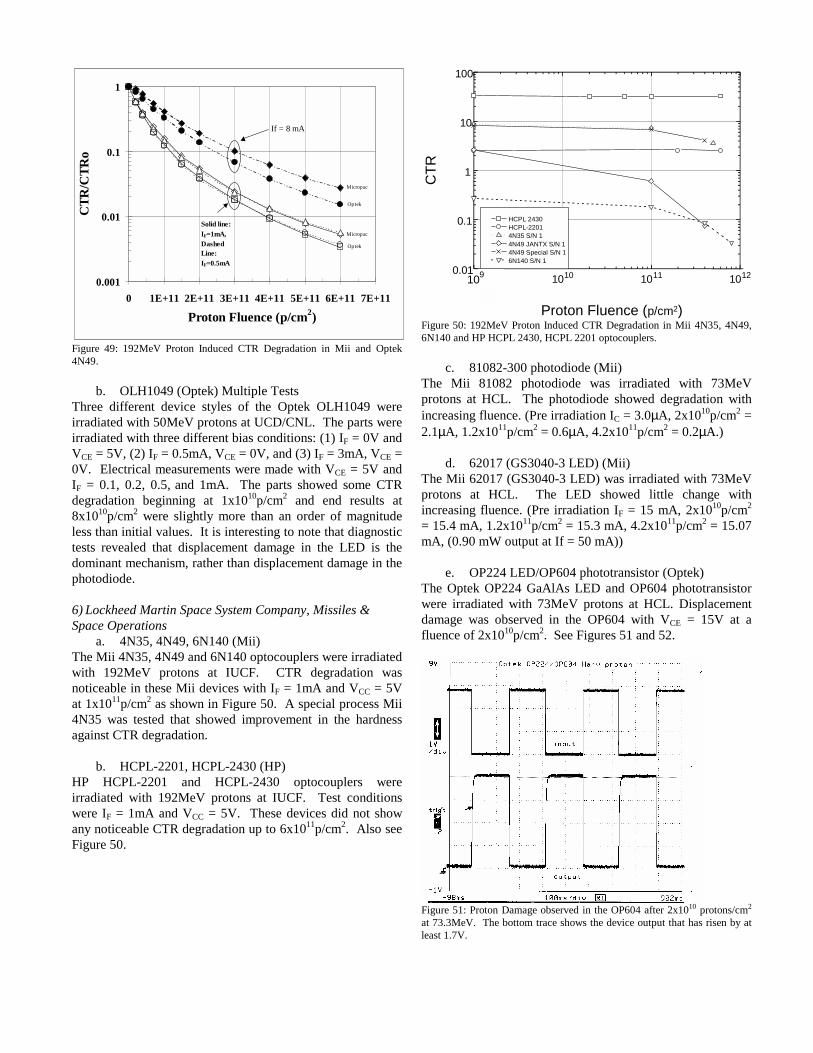
f. 6N134 (Mii)The 6N134 was irradiated with 68, 103, 159 and 225MeVprotons at TRIUMF. Transients were observed with the biasoff for all proton energies. See Figure 59.
0.00E+00
5.00E-07
1.00E-06
1.50E-06
2.00E-06
2.50E-06
3.00E-06
3.50E-06
4.00E-06
4.50E-06
0 20 40 60 80 100 120
Angle of Incidence
Cro
ss S
ectio
n (c
m2)
68MeV 103MeV 159MeV 225MeV
Figure 59: SET Cross Section vs. Angle of Incidence for Various ProtonEnergies in 6N134.
g. 6N136 (Mii)The Mii 6N136 was irradiated with 38.2MeV protons atUCD/CNL. No transients were observed with the bias off, upto 1x10⁹p/cm2. Complete technical data, along with testprocedures and results are available [1,6,15].
h. 6N140A (HP)The HP 6N140A was irradiated with 38.2MeV protons atUCD/CNL. No transients were observed with the bias off, upto 1x10⁹p/cm2. Complete technical data, along with testprocedures and results are available [1,6,15].
i. 6N140 (Mii)Validation of an optocoupler spaceflight experiment that is tobe flown on STRV-1d was done at TRIUMF using 58MeVprotons with a minimum fluence of 2x10¹⁰p/cm2. Mii’s 6N140was tested and no SETs were observed [6].
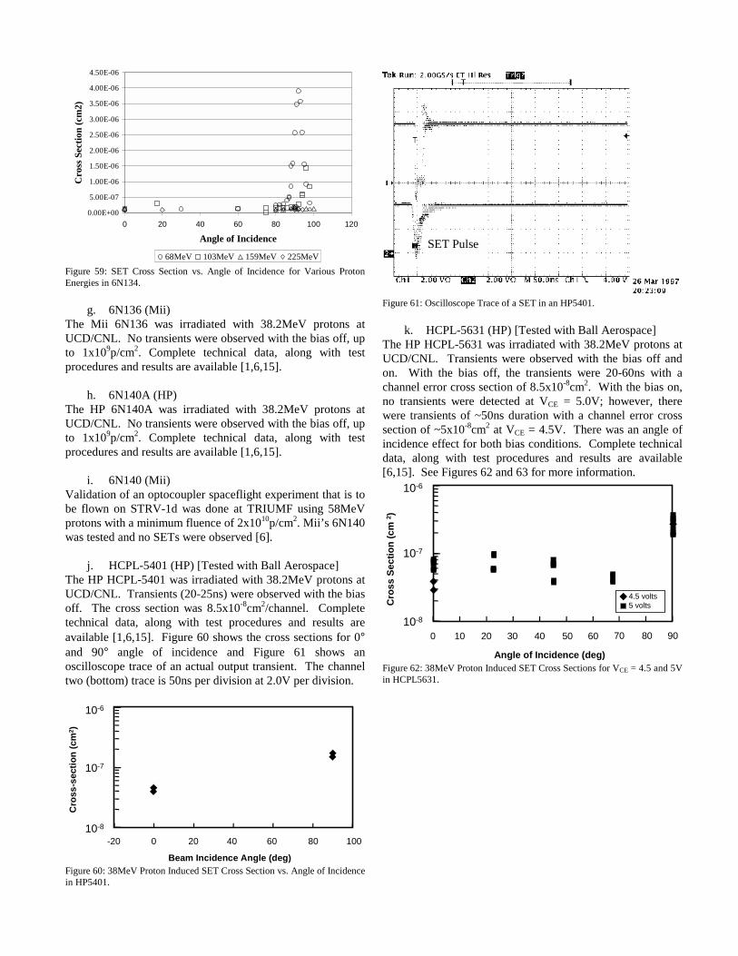
j. HCPL-5401 (HP) [Tested with Ball Aerospace]The HP HCPL-5401 was irradiated with 38.2MeV protons atUCD/CNL. Transients (20-25ns) were observed with the biasoff. The cross section was 8.5x10⁻⁸cm2/channel. Completetechnical data, along with test procedures and results areavailable [1,6,15]. Figure 60 shows the cross sections for 0°and 90° angle of incidence and Figure 61 shows anoscilloscope trace of an actual output transient. The channeltwo (bottom) trace is 50ns per division at 2.0V per division.
Cro
ss-s
ectio
n (c
m2 )
-20 0 20 40 60 80 10010-8
10-7
10-6
Beam Incidence Angle (deg)Figure 60: 38MeV Proton Induced SET Cross Section vs. Angle of Incidencein HP5401.
SET Pulse
Figure 61: Oscilloscope Trace of a SET in an HP5401.
k. HCPL-5631 (HP) [Tested with Ball Aerospace]The HP HCPL-5631 was irradiated with 38.2MeV protons atUCD/CNL. Transients were observed with the bias off andon. With the bias off, the transients were 20-60ns with achannel error cross section of 8.5x10⁻⁸cm2. With the bias on,no transients were detected at VCE = 5.0V; however, therewere transients of ~50ns duration with a channel error crosssection of ~5x10⁻⁸cm2 at VCE = 4.5V. There was an angle ofincidence effect for both bias conditions. Complete technicaldata, along with test procedures and results are available[6,15]. See Figures 62 and 63 for more information.
Cros
s Se
ctio
n (c
m 2 )
10-8
10-7
10-6
Angle of Incidence (deg)
70 80 900 10 20 30 40 50 60
4.5 volts5 volts
Figure 62: 38MeV Proton Induced SET Cross Sections for VCE = 4.5 and 5Vin HCPL5631.

1.00E-08
1.00E-07
1.00E-06
1.00E-05
0 20 40 60 80 100
Angle of Incidence (deg)
Cro
ss S
ectio
n (c
m2 )
38.2MeV 63MeV
Figure 63: HCPL5631 Cross Section Data for Various Angles of Incidence at38 and 63MeV.
l. HCPL-6651 (HP)Validation of an optocoupler spaceflight experiment that is tobe flown on STRV-1d was done at TRIUMF using 58MeVprotons with a minimum fluence of 2x10¹⁰p/cm2. Three seriesof tests were run on the HP HCPL-6651. With no filter, SETswere observed. Tests with passive and active filters showedno SETs [6]. Some angle of incidence data was taken as well.See Figure 64.
0.E+00
1.E-08
2.E-08
3.E-08
4.E-08
5.E-08
6.E-08
7.E-08
8.E-08
0 10 20 30 40 50 60 70
Proton Energy (MeV)
Cro
ss S
ectio
n (c
m2 )
Channel 1Channel 2
Figure 64: SET Cross Section vs. Proton Energy for HCPL6651.
Proton-induced SETs were observed for several angles andproton energies at TRIUMF. SETs were also observedduring irradiation with 240MeV He ions at various angles atMSU/NSCL. A complete description is given in [1,7]. Forthis application, the proton cross section at 220MeV was1x10-8cm2 per optocoupler channel and did not vary withangle. However, there was angular dependence with 70MeVprotons. The proton cross-section at 0 degrees was 1x10⁻⁸cm2
and at 90 degrees it was 1x10⁻⁷cm2.
m. OLH249 & OLH5601(Isolink)Heavy ion SET testing was performed at MSU/NSCL. SETswere observed on these two devices at a LET of 37MeV•cm2/mg for both devices. Cross sections were notcomputed [7,9].
n. OLH5601(Isolink)Proton SET testing was performed at TRIUMF. The deviceswere irradiated with 68, 103, 159, and 225MeV protons. SeeFigure 65.
1.E-08
2.E-08
3.E-08
4.E-08
5.E-08
6.E-08
7.E-08
0 20 40 60 80 100 120Angle of Incidence (deg)
Cro
ss S
ectio
n (c
m2 )
68MeV 103MeV 159MeV 225MeV
Figure 65: OLH5601 Cross Section vs. Angle of Incidence for VariousProton Energies.
o. P2824 (Hamamatsu)Validation of an optocoupler spaceflight experiment that is tobe flown on STRV-1d was done at TRIUMF using 58MeVprotons with a minimum fluence of 2x10¹⁰p/cm2. TheHamamatsu P2824 was tested and no SETs were observed[6].
2) Jet Propulsion Lab, NASAa. 6N134 (HP)
The HP 6N134 was irradiated with various heavy ions atBNL [10]. The cross section results are presented in Figure66.
0.E+00
1.E-03
2.E-03
3.E-03
4.E-03
0 10 20 30 40LET (MeV-cm2/mg)
Cro
ss S
ectio
n (c
m2 )
40 µm range
Figure 66: Heavy ion SET cross section results for 6N134.
b. 6N140 (HP)The HP 6N140 was irradiated with various heavy ions atBNL [10]. The cross section results are presented in Figure67.

1E-5
1E-4
1E-3
0 10 20 30LET (MeV-cm2/mg)
Cro
ss se
ctio
n (c
m2)
Figure 67: Heavy ion SET cross section results for 6N140.
3) Lockheed Martin Space System Company, Missiles &Space Operations
a. 4N35, 4N49, 4N49 special process, 6N140 (Mii),The Mii 4N35, 4N49, 6N140 optocouplers were irradiatedwith 44 to 192MeV protons at IUCF. The protons were atnormal incidence to the devices under test with VCE = 5V.The trigger level was set to capture 0.5V or greater transients.The 4N35 showed no SETs to 5x10¹¹p/cm2, both 4N49sshowed no SETs to 4x10¹¹p/cm2 and the 6N140 showed noSETs to 8x10¹¹p/cm2.
b. HCPL-2201, HCPL-2430 (HP)The HCPL-2201 and HCPL-2430 were irradiated with 44 to192MeV protons at IUCF. The protons were at normalincidence to the devices under test with VCE = 5V. Thetrigger level was set to capture 0.5V or greater transients.The transient upset cross sections measured for these devicesare shown in Figure 68.
0 50 100 150 20010-10
10-9
10-8
10-7
10-6 HCPL 2430 S/N2 HCPL 2430 S/N1 S/N1 beam parallel to chip HCPL-2201 S/N6
Cro
ss S
ectio
n (c
m2 )
Proton Energy (MeV)Figure 68: HCPL2201 and HCPL2430 Cross Sections for Various ProtonEnergies.
c. 61082-300 photodiode (Mii)The 61082-300 photodiode was irradiated with 73 and145MeV protons at HCL. Figures 69 and 70 are traces of thetransients captured. With 10mV logic signals, transientglitches as large as 4mV were detected superimposed on theLO and HI digital signals. The top trace is the input signal,
while the lower trace (magnified by 5x), is the output signalfrom the photodiode. Quantitative measurements of thefrequency of these glitches as a function of incident angle andproton energy were not performed.
Input
Output
SET
Figure 69: 61082 SET Observed on Output Low.
Input
Output
SET
Figure 70: 81082 SET Observed on Output High.
d. OP604 phototransistor (Optek)The OP604 phototransistor was irradiated with 75 and145MeV protons at HCL with VCE = 5V. No transients wereobserved in the phototransistor.
4) Naval Research Labs
QCPL-6637 (HP)The QCPL-6637 was irradiated with 63MeV protons atUCD/CNL. The protons were normally incident and VCE =5V. With a 20pf capacitor, σ = 3.7x10⁻⁸cm2/channel and witha 100pf capacitor, σ = 2.8x10⁻⁸cm2/channel. The lattercondition was measured with a 1GHz oscilloscope and theoutput transients were 55ns ±10%.

C. Total Ionizing DoseSandia National LabsFive 4N49 and five OLH249 optocouplers were irradiated atSandia National Laboratories Radiation Hardness AssuranceDepartment Co-60 irradiator and characterized for theirresponse to TID irradiation. Optocouplers were irradiated toa TID of 1Mrad(SiO2) in logarithmic steps with Co-60gamma rays with zero input and output bias (all pins shortedtogether) at a dose rate of 50rad(SiO2)/s. After each radiationstep, the output current (IC) was measured for output voltages(VCE) ranging from 0 to 10V and for input currents (IF)ranging from 0.5 to 20mA. Figures 71 and 72 showdegradation of CTR for IF = 1mA and for VCE = 2, 5, and 8Vfor 4N49 and OLH249 optocouplers, respectively. As notedin the figures, the 4N49 optocouplers show considerably moredegradation in CTR with TID than the OLH249 optocouplers.
TID [rad(SiO2)]103 104 105 106
CTR
/CTR
o
0.0
0.2
0.4
0.6
0.8
1.0
Co-604N49IF = 1mA
2 V5 V
VCE = 8 V
Figure 71: 4N49 Co-60 TID Induced CTR Degradation.
TID [rad(SiO2)]103 104 105 106
CTR
/CTR
o
0.6
0.7
0.8
0.9
1.0
Co-60ISO249IF = 1mA
VCE = 2 V
5 V
8 V
Figure 72: OLH249 Co-60 TID Induced CTR Degradation.
VII. APPLICATION OF TEST DATA
A radiation data point on an optocoupler, as such, is oflimited use. Interpretation of that data for an actual spaceflight application is a complex task. In this section, we willprovide several lessons learned in this arena.
A. Damage Issues
Predicting CTR degradation for a specific applicationinvolves obtaining damage test data for appropriate testparticle energies for devices operating with appropriatecircuit parameters (VCC, VCE, If, IC, Load). These results mustbe mapped over to the mission-specific transported radiationenvironment.
Some devices may have significant part to part variance [9].In the case of the 3C91C presented here, the initial CTRvaried by as much as 44 (absolute value) in the same lot. Theresulting CTR degradation curves had very different slopes.
Operating parameters can also affect the level of degradationof degradation an optocoupler exhibits in a given application.If a device’s collector current is saturated (for example, forVCE sufficiently low), radiation-induced changes in LEDoutput will have little effect on the optocoupler output. Thisresults in nearly constant CTR with increasing dose until thefluence is large enough to significantly degrade the LEDoutput. The degradation vs. fluence curve then assumes itsmore characteristic exponentially decreasing form. If VCE
were high to begin with, small changes in forward currentwould produce much larger changes in CTR, resulting in amore typical degradation plot even for low fluences.
When significant CTR degradation is expected for a specificmission application, the effects of the degradation can bemitigated in some cases. This can be done by derating theCTR or by adjusting the application bias conditions to reducethe severity of the degradation.
We strongly recommend determining CTR degradation as afunction of proton energy. Although attempts have beenmade to utilize the non-ionizing energy loss (NIEL) function,the risks of this approach are quite high due to the uncertaintyin the dominant degradation mechanism for hybridoptocouplers (Si PIN diode or GaAlAs LED) [4].
B. SET Issues
For SETs, it is important to understand not only whethertransients are possible, but also whether the SETs canpropagate downstream of the optocoupler to produce system-level data errors. Such errors can result in problems similarto those seen on-orbit in HST and Iridium [16]. The endresult of a transient will depend on the pulse width and height,the speed of the device and the characteristics of the circuitrydownstream. For slower devices, the transient may be filteredout because its duration is less than a clock cycle. In fasterdevices, one may need to provide passive filtering, activefiltering or multiple channel voting by follow-on circuitry toremove the transient and prevent data corruption or loss [1].

There is a significant dependence of SET cross section onangle and energy. Increasing the angle of incidence results ina longer path length for the particle to generate charge in thediode. The increase in path length increases the probabilitythat the deposited charge will be sufficient to cause a transientin the device. Often the cross section can increase by anorder of magnitude or more compared to the cross section atnormal incidence.
NASA is currently developing SET prediction methods thataccount for the contributions of both direct and indirectionization [17].
VIII. OTHER RECOMMENDATIONS
1. Application-specific testing on a large sample size is, asalways, recommended whether performing tests fordamage or SET, especially if the optocoupler isperforming a mission critical function.
2. When interpreting a proton damage set, it is important tohave application-specific data or failing that, havegeneric data that bounds (high and low) the actualapplication.
3. SET tests should be performed over a range of protonenergies and angles in order to perform proper ratecalculations. Heavy ion contributions must also bequantified.
4. Items such as sample-to-sample variance, extrapolationof generic test data to a specific application, theapplication of NIEL, annealing, and the effects of agingdrive recommendations for significant pre-missionradiation design margins to be used for degradationissues.
5. Linear stability versus absolute CTR must be consideredfor device selection. A designer may have to review datafrom two different parts that serve the same function.One may degrade only very slightly with increasingfluence, the other, significantly. However, the devicethat degrades significantly may still have a higher CTRafter degradation than the less sensitive device, making itthe better choice for the designer. On the other hand, ifCTR stability is desired, the less radiation sensitivedevice might be the proper choice.
IX. ACKNOWLEDGMENT
The authors would like to thank the NASA/ElectronicsRadiation Characterization Project and the Defense ThreatReduction Agency, Radiation Tolerant MicroelectronicsProgram (Contract Number 00-3001) for supporting thiswork.
X. REFERENCES
[1] K.A. LaBel, et al. “Proton-Induced Transients in Optocouplers: In-Flight Anomalies, Ground Irradiation Test, Mitigation andImplications.” IEEE Trans. Nuc. Sci. 44(6), December 1997: 1885-1892.
[2] C.E. Barnes, et al. “Radiation Effects in Optoelectronic Devices.”Sandia Report, SAND84-0771, 1994.
[3] A.H. Johnston, et al. “Proton Degradation of Light-Emitting Diodes.”IEEE Trans. Nuc. Sci., 46(6), December 1999: 1781-1789.
[4] R.A. Reed, et al. “Energy Dependence of Proton Damage in AlGaAsLight-Emitting Diodes.” Paper to be presented at 2000 IEEE NSRECConference.
[5] B.G, Rax, et al. “Total Dose and Proton Damage in Optocouplers.”IEEE Trans. Nuc. Sci., 43(6), December 1996: 3167-3173.
[6] M.V. O’Bryan, et al. “Single Event Effect and Radiation DamageResults for Candidate Spacecraft Electronics.” IEEE Radiation EffectsData Workshop, July 1998: 39-50.
[7] R.A. Reed, et al. “Emerging Optocoupler Issues with EnergeticParticle-Induced Transients and Permanent Radiation Degradation.”IEEE Trans. Nuc. Sci., 45(6), December 1998: 2833-2841.
[8] M. D’Ordine. “Proton Displacement Damage in Optocouplers.” IEEERadiation Effects Data Workshop, July 1997: 122-124.
[9] M.V. O’Bryan, et al. “Recent Radiation Damage and Single EventEffect Results for Microelectronics.” IEEE Radiation Effects DataWorkshop, July 1999: 1-14.
[10] A.H. Johnston, et al. “Single-Event Upset Effects in Optocouplers.”IEEE Trans. Nuc. Sci., 45(6), December 1998: 2867-2875.
[11] A.H. Johnston, et al. “Angular and Energy Dependence of ProtonUpset in Optocouplers.” IEEE Trans. Nuc. Sci., 46(6), December1999: 1335-1341.
[12] R.A. Reed, et al. “Test Report of Proton and Neutron Exposures ofDevices That Utilize Optical Components an are Contained in theCIRS Instrument.”http://radhome.gsfc.nasa.gov/radhome/papers/i090397.html
[13] G. Jackson. “Radiation Test Results for the Hewlett Packard HSSR-7110 Optocoupler.”http://radhome.gsfc.nasa.gov/radhome/papers/d121696.htm
[14] Unpublished GSFC test report, 3/26/98.[15] R.A. Reed. “Test Report for Proton Induced Single Event Transients in
Optocouplers.”http://radhome.gsfc.nasa.gov/radhome/papers/d031997.htm
[16] B. Heidergott. “Iridium and Celestri Constellation Update.” 11th SEESymposium, April 1998.
[17] K.A. LaBel, NASA/GSFC, personal communication, 2000.