a comparison between hybrid method technique and transfer
TRANSCRIPT

© Faculty of Mechanical Engineering, Belgrade. All rights reserved FME Transactions (2021) 49, 494-500 494
Received: January 2021, Accepted: March 2021 Correspondence to: Barhm Mohamad, PhD student, Faculty of Mechanical Engineering and Informatics, University of Miskolc, Miskolc, Hungary E-mail: [email protected] doi:10.5937/fme2102494M
Barhm Mohamad University of Miskolc
Faculty of Mechanical Engineering and Informatics
Hungary
Jalics Karoly University of Miskolc
Faculty of Mechanical Engineering and Informatics
Hungary
Andrei Zelentsov Bauman Moscow State Technical University
Piston Engine Department Russia
Salah Amroune
Université Mohamed Boudiaf Algeria
A Comparison Between Hybrid Method Technique and Transfer Matrix Method for Design Optimization of Vehicle Muffler Hybrid mufflers are now commonly equipped to decrease vehicle noise and are a crucial tool for regulation of the acoustic system. In order to ensure optimum engine efficiency, the system is intended to dump the strength of the acoustic pulses generated from the engine, and the back pressure created by these systems must be held to a minimum. Typically, modern mufflers have a complex structure of chambers and flow paths. There are a number of mechanisms for sound dampening that operate to silence the sound flowing through a muffler and piping device. This research introduces an important approach to optimize the transmission loss of hybrid muffler Formula student race car (FS) by using both experimental and analytical methods. For this analysis, two methods of calculation were chosen. The muffler has a complex partition located within the muffler chamber, which is a perforated pipe. For the creation of the Finite Element Analysis (FEA) model in AVL BOOST solver and another commercial advanced design software, the muffler CAD file was developed. Experi-mental measurements using a two-load method validated the FEA model. Reliable tests were conducted to verify the design parameters and optimize the muffler's transmission loss (TL) after the model was checked. The findings of experimental and machine analysis are included in the paper. For different measurement methods, recommendations are made for achieving optimum transmission loss curves. Keywords: Exhaust system, Transfer matrix method, Two-load method, Impedance tube, Johnson–Champoux–Allard model (JCA), Transmission loss
1. INTRODUCTION
A vehicle's overall NVH output can be diagnosed using a muffler and plays an important role in the automotive industry. To classify its output, the transmission loss (TL) and the insertion loss (IL) in dB of the muffler are generally used. There are multiple techniques that exist in the acoustic measurement and design approaches of modern exhaust mufflers. Three types of mufflers are available on the market: resistive (dissipative), reflec-tive (reactive) and hybrid. The absorbing materials are used in the first form. For high frequencies, this form is used. The energy is transformed into heat and dissipated after that. The method of reflecting the second form of wave is used to minimize noise. For low frequencies, this is used. The third kind is a reflective and absorptive mix. For all ranges of frequencies, we may use a hybrid muffler [Cherng et al. 2015]. The goal of this research is to perform a reliable analysis on three main design parameters of the Formula race car muffler, i.e., partition position, variance in chamber volume, and the
efficacy of perforated pipe within a hybrid muffler. Mohamad et al. 2017 describe in their scientific paper the type of the muffler used in the industry. This review demonstrates the distribution of flow and temperature along the ducts of the muffler. The techniques for various approaches were utilized experimentally and theoretically to specify transmission loss characteristics in the design, measurement and construction of the muffler. 1D measurements are much quicker, and still provide a clear overview of the device under analysis. Mohamad and Zelentsov 2019 improved sound pressure level (SPL) and reveal the influence of fluid dynamic characteristics by describing an approach of the optimization process range from 1D to full 3D CFD simulation, exploring hybrid methods based on the 3D tools integration of a 1D model. Mohamad and Am-roune 2019 used Computational Fluid Dynamic (CFD) techniques to explore the influence of flow on the acoustic level of the engine exhaust chamber. It demon-strates the transmission loss of the muffler using 1D boost solver at different frequencies. Mohamad et al 2019 used the transfer matrix (TMM) approach to perform a muffler's transmission loss and the algorithm was implemented for other areas of the exhaust system, and also a comparison was observed with CFD data as a result of their analysis of the current muffler. For fresh muffler design, the transmission loss was optimized;

FME Transactions VOL. 49, No 2, 2021 ▪ 495
other literatures played an essential role to validate their results. Mohamad 2019 applied the Ffowcs Williams and Hawkings acoustical model on the Audi A6 C6 2.0 TDi muffler. Flow field and acoustic field were per-formed in the research study. The flow noise level in the muffler was investigated using ANSYS Fluent solver and the boundary conditions of the inlet and outlet pipes were defined.
Figure 1. FS car
The results provided a theoretical basis for studying measures for the station to prevent and reduce muffler noise. Mohamad 2019 explained, through the literature review, several new techniques in the field of muffler design, and the latest development on exhaust systems in terms of acoustic efficiency, as well as a source characterization tool that can be used to connect the experimental and analytical methods. This research
paper took the exhaust muffler of Formula Student (FS) car engine as the research object (Figure 1). By applying the finite element analysis method combined with two-load experiment method, the influence of the structure parameters, including absorptive materials, on the acoustic performance of the muffler was studied and the structure parameters optimization were obtained. Better noise cancellation effect was achieved and provided a certain reference for the structural improvement of the similar muffler.
2. THEORETICAL MODELING
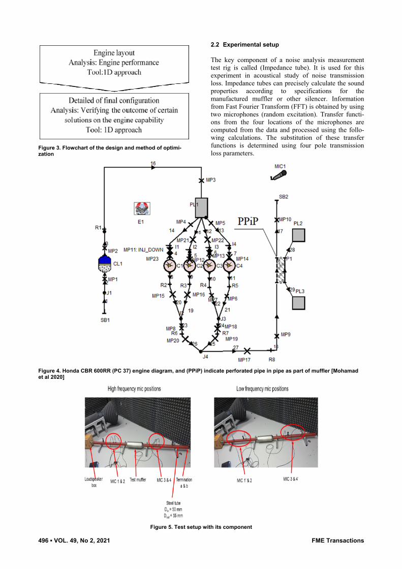
The geometry was implemented using SolidWorks 2017 advanced design software, including inlet, outlet, perfo-rated pipe and chamber, based on the existing FS hybrid muffler prototype (volume). The perforated pipe was mounted in the centre of the muffler's cylindrical-sha-ped chamber. The dimensions and the cross section of muffler and the entire system are described in Figure 2.
2.1 Simulation setup Tools for computational fluid dynamics were intro-duced, and many modeling procedures were set up. Using AVL BOOST optimization, the optimum design for case research was developed. The boundary condi-tions were formulated for the flow analysis to indicate the progress of the exhaust system at multiple engine speed. Figure 3 shows the procedure taken for this simulation.
Figure 2. The dimensions and the cross section of the FS car exhaust system [Mohamad et al 2020]
496 ▪ VOL. 49, No 2, 2021 FME Transactions
Figure 3. Flowchart of the design and method of optimi-zation
2.2 Experimental setup The key component of a noise analysis measurement test rig is called (Impedance tube). It is used for this experiment in acoustical study of noise transmission loss. Impedance tubes can precisely calculate the sound properties according to specifications for the manufactured muffler or other silencer. Information from Fast Fourier Transform (FFT) is obtained by using two microphones (random excitation). Transfer functi-ons from the four locations of the microphones are computed from the data and processed using the follo-wing calculations. The substitution of these transfer functions is determined using four pole transmission loss parameters.
Figure 4. Honda CBR 600RR (PC 37) engine diagram, and (PPiP) indicate perforated pipe in pipe as part of muffler [Mohamad et al 2020]
Figure 5. Test setup with its component

FME Transactions VOL. 49, No 2, 2021 ▪ 497
Figure 6. Two-load method measurement
2.3 Transfer Matrix Method [TMM] The two-load method is an approach described for measurement of the transfer matrix formulation. As shown in the equation below [Hua and Herrin 2013], an acoustical component can be modelled by its four-pole parameters. Neglecting air flow, it is possible to explore the four pole parameters for components 1 - 2 as:
( ) ( )( ) ( )
12 1212 12
1212 12 12
cos cossin
cos
Kl i KlA B
i KlC D Kl
c
ρ
ρ
⎡ ⎤⎡ ⎤ ⎢ ⎥=⎢ ⎥ ⎢ ⎥⎣ ⎦ ⎢ ⎥⎣ ⎦
(1)
The four pole parameters of components 2 - 3 can be defined as:
23 23
23 23
A BC D⎡ ⎤⎢ ⎥⎣ ⎦
(2)
where:
( ) ( )( )
( )( )
( )( ) ( )( )( )
( ) ( )( )
34 32 34 32 34 34 32 3223
34 34
34 32 3223
34 34 34
31 12 32 34 34 34 31 12 32 34 3423
12 34 34 34
34 31 31 12 32 3223
12 34 34 34
a b b a b a
a b
a b
b a
a a b b b a
b a
a b b a
b a
H H H H D H HA
H H
B H HB
H H
H A H H D H A H HC
B H H
B H H A H HD
B H H
Δ − + −=
Δ −
−=Δ −
− Δ − − − Δ=
Δ −
− − −=
Δ −
(3)
The term Hij represents transfer function between the sound pressure pi and pj (Hij) = (pj /pi). The four pole parameters of components 3 - 4 can be defined as:
( ) ( )( ) ( )
34 3434 34
3434 34 34
cos cossin
cos
Kl i KlA B
i KlC D Klc
ρ
ρ
⎡ ⎤⎡ ⎤ ⎢ ⎥=⎢ ⎥ ⎢ ⎥⎣ ⎦ ⎢ ⎥⎣ ⎦
(4)
The final transfer matrix after cascading the last matrices and rearranging is as follows:
14 14
14 14
23 23 34 3412 12
23 23 34 3412 12
A BC D
A B A BA BC D C DC D
⎡ ⎤=⎢ ⎥
⎣ ⎦⎡ ⎤ ⎡ ⎤⎡ ⎤⎢ ⎥ ⎢ ⎥⎢ ⎥
⎣ ⎦ ⎣ ⎦ ⎣ ⎦
(5)
Pressure measurement experimentation consists primarily of the analyser setup and post-processing data for TL calculation. For a frequency range approximately from 0 to 3000 Hz, the experiment is performed. where: K is the number of acoustic waves (rad/m), L is the length of a rigid straight pipe for the propagation of
plane waves (m), c is the speed of sound in medium (m/s) and ρ is the density of fluid (kg/m3). Two separate loads impedances (ZA and ZB) must be added to the output of the device in this process, and then four unknowns and four equations A, B, C, D are four pole parameters of the test component.
This matrix can be represented in the muffler as having one geometry. So, you can calculate the transfer functions as well. The overall value of TL [dB] relies on the complexity and orientation of the muffler. Accor-ding to the figure in the slide above, it is possible to describe the total value of TL for a complex muffler as:
1410 14 14 14
120log2
BTL A C c D
cρ
ρ⎛ ⎞
= + + +⎜ ⎟⎝ ⎠
(6)
With regard to boundary conditions, two set-up configurations are used.
2.4 Johnson–Champoux–Allard model (JCA): This is a model utilized for the measuring the coeffi-cient of acoustic absorption and the propagation of so-und in porous materials. The advantage of the JCA mo-del based on the forecast data, is that it not only pre-dicted acoustic features very well but also showed gene-ral consistency with the results of the experimental tests. [Taban et al 2019].
Allard and Champoux 1992 defined the density module and the equivalent bulk as below:
( )( )
0.52
00 2
0
41 1
ij
α ηωρσφρ ω α ρωρ α σ φ
∞∞
∞
⎡ ⎤⎛ ⎞⎢ ⎥⎜ ⎟= + +⎢ ⎥⎜ ⎟Λ⎝ ⎠⎢ ⎥⎣ ⎦
(7)
( ) ( )
( )
110.52
00 2 2
0
481 1 1 Pr
pr
i NK kp k k
i Nα η ωρηα φ
ωλ φ ωρ α σ φ
−−
∞∞
∞
⎛ ⎞⎡ ⎤⎛ ⎞⎜ ⎟⎢ ⎥⎜ ⎟⎜ ⎟= − − + +⎢ ⎥⎜ ⎟⎜ ⎟⎜ ⎟⎢ ⎥Λ⎝ ⎠⎜ ⎟⎣ ⎦⎝ ⎠
(8)
The physical parameters of the sample include porosity φ [-], air flow resistivity σ [Ns/m4], viscous characteristic length Λ [μm], tortuosity α∞ [-] and thermal characteristic length Λ [μm]. Meanwhile, Npr is Prandtl number [≈0:71], the ρ0 indicates air density [kg/m3], η is the viscosity of the air [≈1:85×10-5], ω is the angular velocity [1/s] and k is the ratio of the specific heat capacity [≈1.4].
To express the characteristic wave number Kω and the characteristic impedance Zc (ω), the impedance of surface acoustic Z can be reformulated from the follo-wing equations [Allard and Daigle 1994]:
498 ▪ VOL. 49, No 2, 2021 FME Transactions
( ) 1cZ Kω ωω ρ
φ= (9)
( ) ( )( )cK
Kρ ω
ω ωω
= (10)
( ) ( )( )cotc cZ Z K dω ω= ⋅ × (11)
0 0
0 0
c
c
z cR
z cρρ
−=
+ (12)
where R is the reflection coefficient of sound pressure in [dB]; d is the thickness of the prototype in [m]; Zc is the surface impedance.
The absorption coefficient is calculated by
21 Rα = − (13)
Finally, the prediction error rates (PERs) of data col-lected from the JCA model at the frequency range between 0-3000 Hz can be calculated for every condi-tion by the equation below:
100m p
mPER
α α
α
−= × (14)
where αm and αp are the measured and predicted absorption coefficients, respectively.
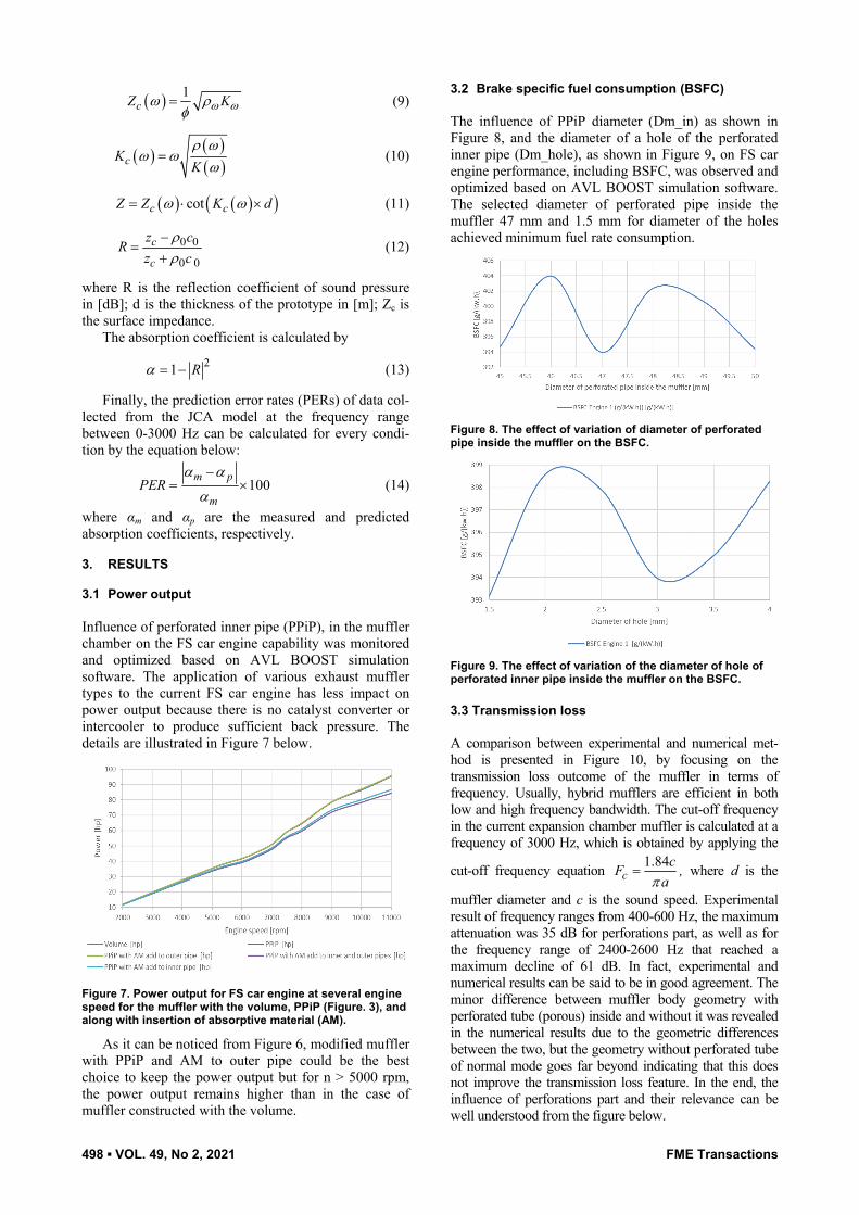
3. RESULTS 3.1 Power output Influence of perforated inner pipe (PPiP), in the muffler chamber on the FS car engine capability was monitored and optimized based on AVL BOOST simulation software. The application of various exhaust muffler types to the current FS car engine has less impact on power output because there is no catalyst converter or intercooler to produce sufficient back pressure. The details are illustrated in Figure 7 below.
Figure 7. Power output for FS car engine at several engine speed for the muffler with the volume, PPiP (Figure. 3), and along with insertion of absorptive material (AM).
As it can be noticed from Figure 6, modified muffler with PPiP and AM to outer pipe could be the best choice to keep the power output but for n > 5000 rpm, the power output remains higher than in the case of muffler constructed with the volume.
3.2 Brake specific fuel consumption (BSFC) The influence of PPiP diameter (Dm_in) as shown in Figure 8, and the diameter of a hole of the perforated inner pipe (Dm_hole), as shown in Figure 9, on FS car engine performance, including BSFC, was observed and optimized based on AVL BOOST simulation software. The selected diameter of perforated pipe inside the muffler 47 mm and 1.5 mm for diameter of the holes achieved minimum fuel rate consumption.
Figure 8. The effect of variation of diameter of perforated pipe inside the muffler on the BSFC.
Figure 9. The effect of variation of the diameter of hole of perforated inner pipe inside the muffler on the BSFC.
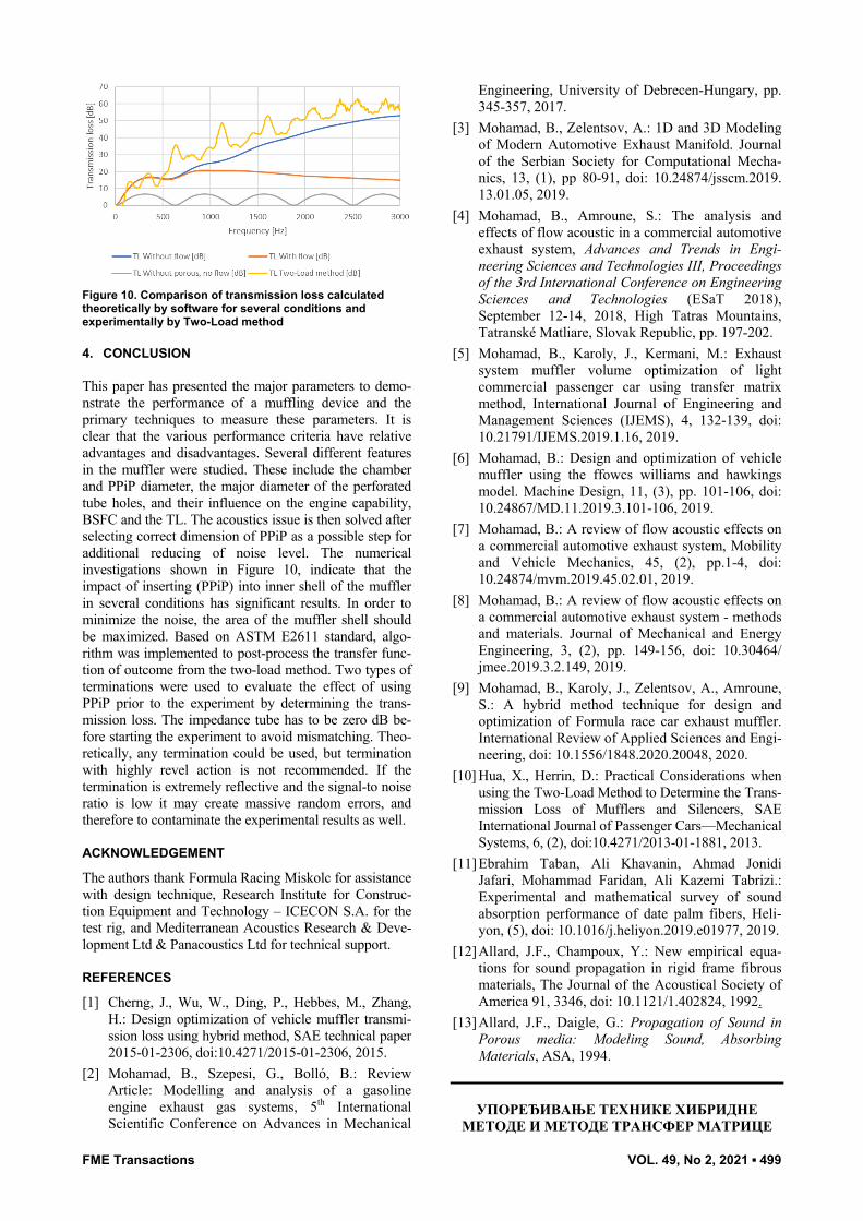
3.3 Transmission loss A comparison between experimental and numerical met-hod is presented in Figure 10, by focusing on the transmission loss outcome of the muffler in terms of frequency. Usually, hybrid mufflers are efficient in both low and high frequency bandwidth. The cut-off frequency in the current expansion chamber muffler is calculated at a frequency of 3000 Hz, which is obtained by applying the
cut-off frequency equation 1.84c
cFaπ
= , where d is the
muffler diameter and c is the sound speed. Experimental result of frequency ranges from 400-600 Hz, the maximum attenuation was 35 dB for perforations part, as well as for the frequency range of 2400-2600 Hz that reached a maximum decline of 61 dB. In fact, experimental and numerical results can be said to be in good agreement. The minor difference between muffler body geometry with perforated tube (porous) inside and without it was revealed in the numerical results due to the geometric differences between the two, but the geometry without perforated tube of normal mode goes far beyond indicating that this does not improve the transmission loss feature. In the end, the influence of perforations part and their relevance can be well understood from the figure below.
FME Transactions VOL. 49, No 2, 2021 ▪ 499
Figure 10. Comparison of transmission loss calculated theoretically by software for several conditions and experimentally by Two-Load method
4. CONCLUSION This paper has presented the major parameters to demo-nstrate the performance of a muffling device and the primary techniques to measure these parameters. It is clear that the various performance criteria have relative advantages and disadvantages. Several different features in the muffler were studied. These include the chamber and PPiP diameter, the major diameter of the perforated tube holes, and their influence on the engine capability, BSFC and the TL. The acoustics issue is then solved after selecting correct dimension of PPiP as a possible step for additional reducing of noise level. The numerical investigations shown in Figure 10, indicate that the impact of inserting (PPiP) into inner shell of the muffler in several conditions has significant results. In order to minimize the noise, the area of the muffler shell should be maximized. Based on ASTM E2611 standard, algo-rithm was implemented to post-process the transfer func-tion of outcome from the two-load method. Two types of terminations were used to evaluate the effect of using PPiP prior to the experiment by determining the trans-mission loss. The impedance tube has to be zero dB be-fore starting the experiment to avoid mismatching. Theo-retically, any termination could be used, but termination with highly revel action is not recommended. If the termination is extremely reflective and the signal-to noise ratio is low it may create massive random errors, and therefore to contaminate the experimental results as well.
ACKNOWLEDGEMENT
The authors thank Formula Racing Miskolc for assistance with design technique, Research Institute for Construc-tion Equipment and Technology – ICECON S.A. for the test rig, and Mediterranean Acoustics Research & Deve-lopment Ltd & Panacoustics Ltd for technical support.
REFERENCES
[1] Cherng, J., Wu, W., Ding, P., Hebbes, M., Zhang, H.: Design optimization of vehicle muffler transmi-ssion loss using hybrid method, SAE technical paper 2015-01-2306, doi:10.4271/2015-01-2306, 2015.
[2] Mohamad, B., Szepesi, G., Bolló, B.: Review Article: Modelling and analysis of a gasoline engine exhaust gas systems, 5th International Scientific Conference on Advances in Mechanical
Engineering, University of Debrecen-Hungary, pp. 345-357, 2017.
[3] Mohamad, B., Zelentsov, A.: 1D and 3D Modeling of Modern Automotive Exhaust Manifold. Journal of the Serbian Society for Computational Mecha-nics, 13, (1), pp 80-91, doi: 10.24874/jsscm.2019. 13.01.05, 2019.
[4] Mohamad, B., Amroune, S.: The analysis and effects of flow acoustic in a commercial automotive exhaust system, Advances and Trends in Engi-neering Sciences and Technologies III, Proceedings of the 3rd International Conference on Engineering Sciences and Technologies (ESaT 2018), September 12-14, 2018, High Tatras Mountains, Tatranské Matliare, Slovak Republic, pp. 197-202.
[5] Mohamad, B., Karoly, J., Kermani, M.: Exhaust system muffler volume optimization of light commercial passenger car using transfer matrix method, International Journal of Engineering and Management Sciences (IJEMS), 4, 132-139, doi: 10.21791/IJEMS.2019.1.16, 2019.
[6] Mohamad, B.: Design and optimization of vehicle muffler using the ffowcs williams and hawkings model. Machine Design, 11, (3), pp. 101-106, doi: 10.24867/MD.11.2019.3.101-106, 2019.
[7] Mohamad, B.: A review of flow acoustic effects on a commercial automotive exhaust system, Mobility and Vehicle Mechanics, 45, (2), pp.1-4, doi: 10.24874/mvm.2019.45.02.01, 2019.
[8] Mohamad, B.: A review of flow acoustic effects on a commercial automotive exhaust system - methods and materials. Journal of Mechanical and Energy Engineering, 3, (2), pp. 149-156, doi: 10.30464/ jmee.2019.3.2.149, 2019.
[9] Mohamad, B., Karoly, J., Zelentsov, A., Amroune, S.: A hybrid method technique for design and optimization of Formula race car exhaust muffler. International Review of Applied Sciences and Engi-neering, doi: 10.1556/1848.2020.20048, 2020.
[10] Hua, X., Herrin, D.: Practical Considerations when using the Two-Load Method to Determine the Trans-mission Loss of Mufflers and Silencers, SAE International Journal of Passenger Cars—Mechanical Systems, 6, (2), doi:10.4271/2013-01-1881, 2013.
[11] Ebrahim Taban, Ali Khavanin, Ahmad Jonidi Jafari, Mohammad Faridan, Ali Kazemi Tabrizi.: Experimental and mathematical survey of sound absorption performance of date palm fibers, Heli-yon, (5), doi: 10.1016/j.heliyon.2019.e01977, 2019.
[12] Allard, J.F., Champoux, Y.: New empirical equa-tions for sound propagation in rigid frame fibrous materials, The Journal of the Acoustical Society of America 91, 3346, doi: 10.1121/1.402824, 1992.
[13] Allard, J.F., Daigle, G.: Propagation of Sound in Porous media: Modeling Sound, Absorbing Materials, ASA, 1994.
УПОРЕЂИВАЊЕ ТЕХНИКЕ ХИБРИДНЕ МЕТОДЕ И МЕТОДЕ ТРАНСФЕР МАТРИЦЕ

500 ▪ VOL. 49, No 2, 2021 FME Transactions
КОД ОПТИМИЗАЦИЈЕ ДИЗАЈНА ПРИГУШНИКА МОТОРНОГ ВОЗИЛА
Б. Мохамад, Ј. Карољи, А. Зеленцов, С. Амрун
Хибридни пригушници треба да смање буку код моторног возила и представљају важан алат за регулисање акустике. Да би се обезбедила оптимална ефикасност мотора, систем треба да редукује јачину звучних импулса које генерише мотор, а повратни притисак мора да се држи на минимуму. Модерни пригушници имају сложену структуру комора и путева протока. Постоји неколико механизама за звучну изолацију који раде тако што смањују јачину звука који пролази кроз пригушник и систем цеви. Ово истраживање уводи нови приступ оптимизацији губитка у преносу код
хибридног пригушника код тркачког аутомобила Формула Студент коришћењем експерименталних и аналитичких метода. Пригушник има један сложени део који се налази у комори пригушника, а који представља једну перфорирану цев. CAD датотека пригушника је направљена за израду FЕА модела коришћењем софтвера AVL BOOST и још једног комерцијалног софтвера за дизајнирање. FEA модел је валидиран експерименталним мерењима применом методе двоструког оптерећења. Параметри дизајна су верификовани тестовима поузданости а оптимизација губитка у преносу после провере модела. У раду су приказани резултати експерименталне и машинске анализе. Код коришћења различитих метода мерења дате су препоруке за постизање оптималних кривих губитка у преносу.