a comparative experimental study of the modulus of ... · a comparative experimental study of the...
TRANSCRIPT

11th INTERNATIONAL BRICKlBLOCK MASONRY CONFERENCE TONGJI UNIVERSITY, SHANGHAI, CHINA, 14 - 16 OCTOBER 1997
A Comparative Experimental Study of the Modulus of Elasticity of Bricks and Masonry.
Y.Z . Totoev l and J.M. Nichols2
1. ABSTRACT
One of the parameters identified as influencing the structural response of buildings is the dynamic Modulus of Elasticity of masonry. The Longitudinal Vibration Test Method and the Ultrasonic Pulse Methods were developed for the dynamic testing of ooncrete specimens. These two dynamic procedures are to be tested on masonry prisms to provide a verification of the methods. The first aim of this paper is to experimentally investigate the use of high frequency sinusoidal dynamic loading to determine the dynamic Modulus of Elasticity of masonry. The second aim is to compare the dynamic
. Modulus ofElasticity results to the Young's Modulus obtained using quasi-static methods. The third aim is to compare the masonry prism results to masonry unit results for the Young' s Modulus, to determine the ratio of Young' s Modulus to the peak stress for the prisms and to calculate the Young' s Modulus for the mortar. A test rig has been developed for measuring the elastic properties of masonry prisms under uni axial static loading. The dynamic and quasi-static samples were tested from the same population of masonry prism samples. A single type of mortar was used for ali experimental work.
2 INTRODUCTION A reasonable proportion ofthe larger masonry buildings and dwellings built within in
. Australia and elsewhere in intraplate regions would have been designed on the basis of
Keywords: Masonry; Modulus ofElasticity; Clay, CaIcium Silicate & Concrete Brick
I Lecturer, DepartmelÍt of Civil, Surveying and Environrnental Engineering, University ofNewcastle,Callaghan, NSW, Australia. 2 Postgraduate Student, Department of Civil, Surveying and Environrnental Engineering, University ofNewcastle,Callaghan, NSW, Australia.
30

static loading design rules and assuming zero or low seismic loads. The design of buildings within Australian now must consider the minimum loading from the AS 1170.4 SAA Earthquake Loads [I] using either an equivalent static loading, frequency domain or time domain analysis. Material properties are required for these methods of analysis, irrespective ofthe numerical method.
There are three objectives to measure the material properties for this paper. The first objective is a deterrnination and comparison of the quasi-statically measured Young's Modulus and the dynamically measured Modulus ofElasticity for masonry prisms. The second objective is to compare the Young's Modulus for the masonry prisms to the mean peak stress for the prisms. The third objective is to calculate a Young's Modulus for the mortar within the joints. The measurement of these properties will meet the aims of the research and provide data for ongoing research work on masonry panels.
This work is part of an investigation into the dynamic structural properties of masonry panels with loading within the seismic ranges for frequency and intensity. This research is based on a single river sand and mortilr type of the highest quality achievable under laboratory conditions. Five brick types are used in the quasi-static and dynamic experiments. Two extruded bricks, one solid and one holed, will be tested with the quasi-static Test Methods.
3 MASONRY CHARACTERISTICS
Three high - stack bonded masonry prisms were constructed from seven difTerent brick types. Three pressed c1ay bricks designated by colour red (RI), brown (B 1), biscuit (B2), one extruded solid dark brown brick(B3), one red extruded (EI) one calcium silicate (Cl) and one concrete brick (C2) were used in the experimental work. A total of 39 specimens were manufactured for the test programo All bricks are of Australian manufacture with a nominal size ofLength: 225, Breadth: 110, Height, 75 millimetres.
The Young' s Modulus the Dynamic Modulus ofElasticity and Poisson's Ratio had been deterrnined for five of the seven bricks(Nichols and Totoev)[2]. A summary of these results is presented in Table 1.
Brick Type
RI Pressed Red B 1 Pressed Brown B2 Pressed Biscuit B3 Extruded Solid
CI Calcium Silicate C2 Concrete
E 1 Red Extruded
Table 1 Brick Properties.
Young's Modulus Mean Range of the GPa Dynamic Modulus
of Elasticity GPa Two Test Methods
14 ± 6 10-12 7±6 12-13 1O±6 7-11
- -7±4 11-14
14± 6 20-21 - -
31
Poisson' s Ratio
0.22 0.21 0.29
-0.17 0.33
-

Prisms were made using a mortar with the following properties by volume, 1: 1:6 cement : lime: sand. The lime in the form of lime putty was aged for two months before the manufacture of the prisms. It was made from hydrated lime and water in equal parts by weight. The putty was sealed in an ai.1ight container until it was used to mak:e .the mortar. Cement was a general purpose grade. The water cement ratio was maintained in the range of 1.9 to 1.96. The flow properties were within the range of 100 to 130 % with a cone penetration of 55 - 60mm. The sand isa river sand from a dredge quarry at Raymond Terrace. The sand has 88 per cent passing the 0.3 mm, 16 per cent passing the 0.15 mm sieve and 0.3 per cent passing the 0.075 mm sieve. It is described as mono sized river sand with a paucity of fines .
Mortar cubes of size 70 ± 1 mm had peak: stress of 2.2 ± 0.2 MPa. A full material science based test program on this type of mortar, other mortars and additives is being completed at Newcastle University by Sugo[3]. Initial results from this seminal research would indicate that this mortar type provides a consistent quality of mortar. A deterioration in strength and quality characteristics occurs with departure from the specified mix or the use of admixtures.
3 ELASTICITY AND DAMAGE MECHANICS THEORY
Young's Modulus, based on the concepts of Damage Mechanics[4], can be defined as an intrinsic and constant property of a material. The measured changes in the Modulus of Elasticity are then defined as being related to the Young' s Modulus (E) by the Damage Sca1ar (D). The Damage Scalar hás a range of O to 1 for a domain ofthe Modulus of Elasticity of E to O. The Damage Mechanic could be established as a scalar to a tensor representation. This brief discussion on the Damage Mechanic shows the direction of the research programo The basis for this initial research work is in establishing the intrinsic elastic properties of masonry units and masonry prisms for a number of unit types.
Hookes' Law (1) defines the Young's Modulus as
cr = EE (1)
There are two field variables. The first variable is the stress cr (expressed in MPa). The second variable is E that is based on the natural strain law ( expressed in milliStrains). Tlie intrinsic elastic constant generally termed Young' s Modulus, E is expressed in GPa. Young' s Modulus can be estimated using the 15 to 85 % stress leveis in the elastic range using a quasi-static test procedure[4,5]. Altemative procedures use secant methods [6,7,8] over different ranges ofthe stress below the yield stress.
A dynamic Modulus of Elasticity was determined from Equation (2) for the Longitudinal Dynamic Test Method [9]
f = ~47:P (2)
32

where the field variables are f which is the measureq fundamental natural frequency (Hz), L is the length of the specimen (m) and pis the density(kg/m\ The dynamic
Modulus of Elasticity defined as E (Pa, although presented as GPa in this paper).
A dynamic Modulus ofElasticity can be determined from Equation (3) using the Ultrasonic Pulse Method [lO). This test method uses the measurement ofthe travei time of ultrasonic pulses in the transverse and longitudinal axes.
V= E (I-u) p (1+uXl-2u)
(3)
The field variables are V which is the measured pulse velocity(mls) and pis the density(kg/m\ Poisson' s ratio u is an intrinsic property measured with the destructive quasi-static testing of the masonry units. A 'nominal' definition is provided for the Poisson's Ratio of the masonry prisms. The ratio is determined over a 210 mm gauge length on the centre brick of the three high stack bonded prism. This method also provides a measure ofthe isotropicity ofthe samples.
We base this distinction between the Young' s Modulus and the Modulus of Elasticity on the observed differences in the primary elastic constant under different testing protocols whether quasi-static or dynamic[ll, 16). The research work will use as a hypothesis that Young's Modulus Is defined over a defined elastic domain using a single quasistatic protocol. Any other protocols or measurements outside the elastic domain will derive a measurement of the Modulus of Elasticity distinguished with a Tilde - for a dynamic protocol and a Bar - for a quasi-static protocol. The Modulus of Elasticity can therefore be definéd as tangential or secant for a quasi-static protocol or a dynamic protocol.
A number of authors have recently looked at the relationship between the characteristic strength of the masonry unit fm ' and the Modulus of Elasticity. A numerical value of 400 to 550 was established by Vermeltfoort[8] and Wolde-Tinsae, et al., [6). The Modulus of Elasticity is defined as the ratio between the two field variables, stress and strain. The definition of the characteristic compressive strength of the masonry r'm provided by the AS 3700 Masonry Code[12] is based on a Wçibull distribution. This method provides a value of a statistically based design quantity ra.,ther than a directly measurable field variable. The ratio of the mean peak stress of the masonry to the Modulus of Elasticity will be reported for these experimental results. A direct measurement of the Modulus of Elasticity of the mortar is not practically feasible with this test protocol. As noted by Davidge[13] "ifan assumption ofisotropicity is made for the two phases and the stress is applied normally to the slllbs, then the stress in each slab is constant and the corresponding composite Young' s Modulus is given by Equation(4)
(4)
where the Modulus of Elasticity of each phase is given by Ej and the volume fraction
of each phase is given by V; .
33
4 EXPERIMENTAL METHOD
The Modulus of Elasticity results for testing of concrete test cylinders is mildly frequency dependent. The results will be reviewed to determine whether there is a frequency dependency for this data.
The quasi-static test protocol for the determination of the Young's Modulus for the brick units uses a staridard rig[2]. The quasi-static test protocol for prisms uses uniaxial compression applied to the larger end brick faces of the three high - stack bonded masonry samples with a Tinius Olsen 1800 kN Universal Testing Machine. Plywood (- 5mm) was used as the 'packing material. Apressure cell in the UTM provides an analog output signal. Initially this signal was converted to a digital signal using a Gedge Systems(Aus) GSI650P Peak Indicator. The analog to digital signal generator proved to be too coarse (± 2.5kN) for this testing ahd caused a substantial component of the error in the measurement. Final testing had the analog signal being fed directly into the data logger. Calibration of the signal was undertaken using the UTM dial scale.
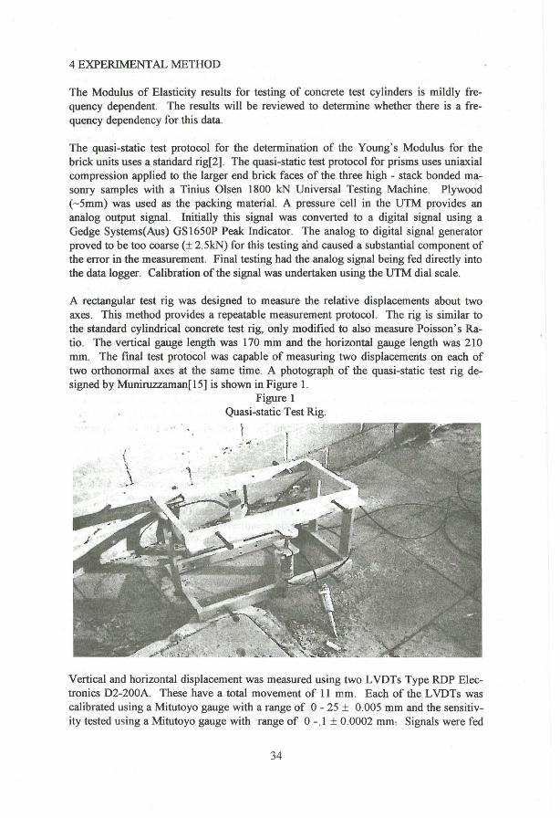
A rectangular test rig was designed to measure the relative displacements about two axes. This method provides a repeatable measurement protocol. The rig is similar to the standard cylindrical concrete test rig, only modified to also measure Poisson's Ratio. The vertical gauge length was 170 mm and the horizontal gauge length was 210 mm. The final test protocol was capable of measuring two displacements on each of two orthonormal axes at the same time. A photograph of the quasi-static test rig designed by Muniruzzaman[l5] is shown in Figure 1.
Figure 1 Quasi-static Test Rig.
. -. , -
r /.~ ' .
Vertical and horizontal displacement was measured using two LVDTs Type RDP Electronics D2-200A. These have a total movement of 11 mm. Each of the L VDTs was calibrated using a Mitutoyo gauge with a range of 0- 25 ± 0.005 mm and the sensitivity tested using a Mitutoyo gauge with range of 0-.1 ± 0.0002 mm, Signals were fed
34

into a Data Ek:tronics Datataker 600. The signals were logged and converted to an ASCII fonuat using DASYLab 3. The results were analysed using a regression macro written for MINITAB 1O.2[l4].
The Longitudinal Test Method uses a dynamic test rig. This rig is a modified version of the Electrodynamic's Standard Material Tester EMFCO SCT/5 (EMFCO, not dated)[9]. This test rig is noted in the specification "as to complying with BS 1881: 52 (Longitudinal Vibration)" Specimens were saw cut from the prisms by sawing into two halves about the longitudonal axis. A Tektronix Function Generator FG501 with controlled frequency was used to generate the applied sinusoidal loading function . This signal was amplified using a Peavey Electronics Corpo XR400 Amplifier to feed the 3 ohm coil on the test rig. Each specimen was c1amped on the test rig using an II mm rad. jaw c1amp at the midpoint of the cut brick. A piezoelectric crystal pickup detects the signal that was monitored on a Tektronix Oscilloscope 7603 for peak amplitude. The frequencies used were in the range from I to 20 kHz. A schematic arrangement of the equipment is shown in Figure 2.
Figure 2 Schematic ofthe Longitudinal Vibration Test Rig
Function Generator X ..... ....;..---~
,---------------------------1 1 ,------------------------, 1
Amplifier ====~ Oscilloscope Ii=J X
Clamp
Specimen I I I I I I X
Exciter
y
Pick-up
The criticaI areas in this type of experimental work are ensuring that the lowest resonant (with multiples) and not spurious frequencies are identified and that the results can be repeated. A steel cylindrical specimen was used as validation of the procedure.
The Dynamic Test Method - Ultrasonic Pulse Method is a standard measurement unit. This method uses the CNS Portable U1trasonic non destructive tester (CNS 1978)[10]. A calibrating specimen is provided with the rig. Testing was at 50 kHz about the longitudinal and transverse axes ofthe specimen. The U1trasonic Pulse Method is insensitive to size effects and has been used to provi de readings in the longitudinal and transverse directions. These results for the detenuination of the Modulus of Elasticity will be re-
35

viewed to identify any masonry units that exhibit isotropic behaviour. A schematic arrangement ofthe equipment is shown in Figure 3.
Figure 3 Schematic ofthe Ultrasonic Pulse Velocity Test Rig.
Pulse Generator
Transmitting transducer
5 RESULTS
Start Stop-watch Ainplifier
~------------------------------- Rx Specimen
..... __________________ ..... Receiving
transducer
These series experiments were undertaken to determine the Young' s Modulus and dynamic Modulus of Elasticity of 3 high- stack bonded masonry prisms. Seven masonry units were tested as prisms. Three pressed bricks, a concrete and a calcium silicate brick were tested to the three protocols. Two extruded bricks were only tested to the quasi-static protocol. The mortar joint was approximately 10 to 12 mm thick for these prisms . . The properties of the mortar were constant for the manufacture of the masonry prisms and the prisms were laid in a random order.
Young' s Modulus and Poisson's Ratio are intrinsic elastic properties measured using the quasi-static test method for the masonry units[2]. The range of Young's Modulus for the masonry units \:'!8S from 1 GPa for a da.r.~aged pressed red to 56 GPa füf a COfl
crete brick. The pressed bricks had some unusual stress strain curves. This small number of unusual curves would suggest that the frog may impact on the variation of density of the brick. Initial results would point to a greater material density and hence greater elastic moduli on the frog side of the brick.
The pressed bricks were non symmetric. The measurement of Young' s Modulus requires the use of averaged results between the two sets of displacement.
Poisson' s Ratio results ranged from about 0.1 to 0.4. The higher result for the concrete brick suggests a lower volume of cracks, smaller cracks and a more uniform crack distribution than thepressed and calcium silicate bricks. Each ofthe c1ay brick specimens showed visual variations on the cut faces that suggests density and material variation across the brick. This density and material variation may be of interest in explaining some of the results for the Modulus of Elasticity. Research is planned to consider numerical modelling of the test procedures to provide a c1earer understanding of the results and the protocol.
36

The test results for the seven brick types are presented in Table 2.
Description Young's Modulus of the Masonry Quasi-static
Protocol (GPa)
RI Pressed 15 ,± 3 Red
Bl Pressed 5±2 Brown
B2 Pressed 6±3 Biscuit
B3 Solid 14 ± 7 Extruded
Table 2 Masonry Test Results
Nominal Calculated Poisson's Young's Ratio for Modulus of
central brick the Mortar in the (GPa)
Prisms 0.25 -
0.13 2
- 2
0.17 -
Peak Stress Ratio ofthe (MPa) Young' s
Modulus of Masonry to
thePeak Stress
19± 4 780
14 ± 4 360
15 ± 3 420
24±4 580
Cl Calcium 5±4 - 2 8±1 610 Silicate
C2 Concrete 5±2 0.10 1 11 ±2 460 El RedEx- 14 ± 5 - - 18 ± 3 750
truded
The results for quasi-static testing of the five masonry units are outlined in Figure 4. These results form the basis for the comparison to the dynamic test results for the different protocols.
Figure 4 Elastic Modulus Test Results for the Masonry units.
25-r~.~Q~u-a~si~-~sta~t~ic~U~n~ia-x~ia~IL~o-a~di-ng-M~et7h-Od~(~<~0 .~I ~H~Z~) ------------+!I---'·~-----' • Longitudinal Vibration M ethod (5- 9 kHz) ~ • Ultrasonic Puls M ethod, long. (50 kHz) I I
20-_~~EE.!!:'!!!.s.J~~E _____ 1- _-.:. ___ + ______ ~- ,-I. _lJ_ X M ean values I I I
I I I I I I I I ls--------i--r-ri --r -t----.-.I- hr---
l:~-~~~Itii~~~~t_~_~~ll:~~~t_~~~~~. I I I I I I I I I I I I
O~---------r---------r---------r---------r--------~ B· 't ' B ' R d I C I . I C t ISCUl pro rown pro e pro a clum oncre e cIay brick c1ay brick c1ay brick silicate brick brick
37

The results for quasi-static & dynamic testing of the five distinctive types of masonry prism are outlined in Figure 5.
Figure 5 Elastic Modulus of Masonry
25~--------.---------.---~~~~~~~~~~~~~ • Quasi-stat.Uniax.Load. Method «0.1 Hz)
I I I I I
------;--------t-20 I I I I I I
------;--------t-
10
5
I ! I I , I
-·-t1-.-·---~ I I I I
-----t-------j-I I I I I I
• Longitudinal Vibration Method (3-5 kHz) • Ultrasonic Puls Method (50 kHz)
~E~í~-----l-----I-
,-,-:-----;1----------t- -'--1-r1----
I I ----r- ----~- -----
I I I I I I
O~--------~--------~--------;_--------;_--------, Biscuit pro cIay bricks ·
6 CONCLUSION
Brown pro cIay bricks
Redpr. cIay bricks
Calcium silicate bricks
Concrete bricks
This work set out to compare the quasi-statically measured Young's Modulus to the dynamically measured Modulus of Elasticity. A set of protocols and two rigs were developed to quasi-statically measure the Young's Modulus of masonry units and masonry prisms. The two dynamic methods used for concrete samples can adequately test different brick types. These two methods are the Longitudonal Vibration and Ultrasonic Pulse Velocity Test Methods. The limitation for these procedures is the frequency dependence ofthe results.
The results for the measurement of the Young's Modulus and Poisson's ratio for the masonry units is presented in Table 1 Brick Properties. Dynamic measurement of the Modulus of Elasticity is a practicable altemative. to quasi-static destructive testing for clay masonry units. There is no evidence of frequency dependence for the clay masonry units, there appears to be a strong frequency dependence for the sand based masonry units. Testing is required using many specimens to quantify the relationship.
A set of 39 three high stack bonded prisms of seven brick types were tested using the quasi-static test method. A total of 23 prisms from the quasi-static test group were first tested using the two dynamic test methods. The results are shown graphically on Figure 5. The results show that the two dynamic methods the L VM and the UPS Method can predict the Modulus of Elasticity albeit with a frequency still evident in the sand based masonry units. The Modulus of Elasticity of the Masonry Prisms was degraded in comparison to the Modulus of Elasticity of ali of the masonry units tested to the three protocols except for the Red Pressed Clay Brick. The scatter in the results would
38

probably account for this single result. The Young' s Modulus for the masonry prisms was compared to the mean peak stress for the prisms to determine the ratio between the two masonry properties. The results show a slight1y higher ratio than would be expected for commercially constructed masonry. This is probably influenced by the mortar strength and stiffness. The results are consistent with the trends reported in the recent American and Italian research. Young' s Modulus for the mortar within the joints has a range of 1 to 2 GPa using the method detailed in Davidge[13]. In summary this research has developed two rigs and protocols to quasi-statically determine quickly and efficiently the Young's Modulus and Poisson's Ratio for a variety of brick tipes . The two dynamic methods the Longitudonal Vibration and the Ultrasonic Pulse Method have been shown to provi de reasonable estimates of the Modulus of Elasticity Two aspects of this work suggests productive future directions for the research. The first direction is to study the effect of varying the mortar properties for a single brick type. Secondly establishing a relationship for the frequency dependence between the different results for the Modulus of Elasticity from the three protocols.
7 REFERENCES
1. Standards Australia., "AS 1170.4 Earthquake loads" Sydney,1993 . 2 Nichols, 1.M., and Totoev, Y.z. , "Experimental determination ofthe dynamic
Modulus of Elasticity of masonry units" accepted for the 15th Australian Con ference on the Mechanics of Structures and Materiais, Melb. Vic., Dec. 1997.
3 Sugo, H., "Personal communication", 1997 4. Krajcinovic., D., Damage Mechanics. New York: EIsevier, 1996 5. LeMaitre, 1. , A course on Damage Mechanics. Berlin : Springer-Verlag, 1992 6 Wolde-Tinsae, AM., Atkinson, R.H., and Hamid, AA, "State ofthe Art
Modulus of Elasticity of Masonry", Proceedings of the Sixth North American Masonry Conference, Phil. Pa., 1993, pp. 1195-1208.
7 Binda, L., Tiraboschi, C., and Abbaneo, S., "Experimental Research to characterise Masonry MateriaIs", Joumal ofthe British Masonry Society, 10,(3) 1997 - pp. 92-101
8 Vermeltfoort, AT., "Properties of Some Clay Bricks under varying Loading Conditions", Joumal ofthe British Masonry Society, 10,(3), 1997 - pp. 85-91
9 EMFCO., Specification for the SCT/5 Test Rig. London: EMFCO: not dated. 10 CNS Electronics Ltd. , Pundit Manual for use with Portable Ultrasonic Non
destructive digital indicating tester. London: CNS: 1978. 11 Freund, L.B.,. Dynamic Fracture Mechanics, Cambridge :Cambridge Uni
versity Press, 1990. 12 Australian Standards., "AS 3700 SAA Masonry Code." Sydney,1988 13 Davidge, R.W., "Mechanical Behaviour ofCeramics" Cambridge Solid State
Science Series, Cambridge :Cambridge Uni versity Press, 1979. 14 Minitab Inc., "Minitab 10.2 Users Manual", State College Pa, USo 1994. 15 Muniruzzaman, A, "Personal communication", 1996. 16 Tercelj, S., Sheppard, P., and Tumsek, V., "The influence offrequency on
the shear strength and ductility ofmasonry walls in dynamic loading tests." Proceedings ofthe Fifth Intemational Conference on Earthquake Engineering. 3:2292 - 9. ..
39