a combined heat and power plant under constant … · västerås heat and power plant is the...
TRANSCRIPT
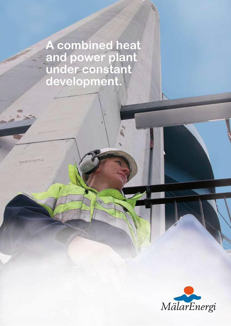
A combined heat and power plant under constant development.

Electricity and heat in an effective and environmentally friendly way.
Västerås Heat and Power Plant is the largest in Sweden and one of the cleanest in Europe. Construction of the plant commenced in the 1960s in order for it to be incorporated in the town's district heating system. Oil was the pri-mary fuel at that time. We are now endeavour-ing to use renewable fuels as far as possible.
The heat and power plant has been ex-tended and converted in several stages. The most recent major extension was carried out in 2000 and comprised a new, modern biofu-el boiler that is now responsible for the basic capacity in the plant, and which is operated all year round for environmentally friendly electricity and district heating production.
A combined heat and power plant produces electricity and heat at the same time.The plant in Västerås is a combined heat and
power plant that produces heat and electrical power simultaneously. The principle involves heating water to produce steam at high pres-sure and a high temperature in a steam boil-er. The steam drives a turbine, which in turn drives a generator that emits electrical cur-rent, which is fed to the electric grid. After the steam has passed the turbine, the re-maining heat energy is transferred to the dis-trict heating network via a condenser.
By producing electricity and heat simultaneously, a very high level of efficiency is achieved. A massive 90 % of the fuel's
energy content can be utilised in the process. By way of comparison, a steam power plant that solely produces electrical energy only utilises around 40 % of the fuel's energy content.
Water
is boiled
to produce
steam
Turbine
Generator
Mains electricity network
District heating network
Condenser
Fuel

Electricity and heat in an effective and environmentally friendly way.
We prefer renewable fuelsA heat and power plant can be fired with many different types of fuel. We primarily use biofuels to fire the plant, i.e. renewable fuels from the forest products and waste that do not produce any carbon dioxide contri-bution when burned. This is in line with Mälarenergi's environmental focus, which is characterised by consideration for nature and the promotion of development that is sus-tainable in the long term. Firing with renew-able fuels is also financially beneficial these days, thanks to the emission trading that is now conducted within the EU. The purpose of this trade is to limit the emissions of car-bon dioxide into the atmosphere, thereby working to counteract climate change, the consequences of which are already becoming noticeable.
Thanks to the heat and power plant, the city of Västerås and neighbouring communities - Skultuna, Tillberga, Hökåsen, Hallstaham-mar and Kolbäck - can be heated in an en-ergy-efficient manner and without polluting the air. We have always been one of the first to invest in various systems for the treatment of flue gases from our boilers, and therefore consider ourselves to be one of the cleanest heat and power plants in Europe.
Effective cleaning technology minimises the
amount of pollutantsThere are primarily two ways to reduce the environmental impact of a combined heat and power plant: to fire with fuels that do not produce any carbon dioxide contribution, and to clean the flue gases of any harmful compounds. We are work-ing consciously with both of these measures.
Carbon dioxide is formed during all combustion. Most carbon dioxide is released when firing with fossil fuels, which in the long term increases the greenhouse effect in the at-mosphere. Biofuels produce no addition to the greenhouse effect, as the released amount of carbon dioxide is absorbed by the growing bio-crops in a natural ecocycle. Biofuels, including peat, now represent approximately 70 % of the heat and power plant's total fuel consumption.
When burning, sulphur oxides and nitrogen oxides are also formed. These contribute for example to the acidifi-cation of forests, arable land and lakes if they are released into the air. The flue gases from our boilers are effectively cleaned of these substances. 95 % of nitrogen oxides and 97 % of sulphur oxides are separated when firing with fuels containing sulphur. When burning biofuels, only negligible amounts of sulphur oxide are formed.
The boilers' cleaning systems also
include filters for removing dust
in the form of airborne ash, as
well as residual products from
the cleaning of sulphur oxide and
nitrogen oxide. The degree of
separation for dust is 99.97 %.
One of Europe's cleanest heat and power plants.

In total, the combi-
ned heat and power
plant comprises four
separate blocks as well
as boiler 5. A block
refers to a boiler and
a turbine. Boiler 5
does not have its own
turbine, but produces
electricity via the
turbine in block 4.
Production is
primarily performed
using renewable bio-
fuels and amounts to
700 GWh of electri-
city and 1,800 GWh
of heat annually.
Blocks 1 and 2The plant's oldest production units
were commissioned in 1963. Both
boilers were converted from oil to
coal in 1981, and have subsequently
also been converted for firing using
tall oil pitch, which is a renewable
fuel. Boiler 1 can also be fired with
peat. Both of these blocks now
operate for peak loads.
Data: block 1 Fuel:
Tall oil pitch, coal, peat
Power and heat production:
40 MW of electricity and
100 MW of district heating
A complete facility with many possibilities.
Block 3Block 3 was commissioned in
1969 and is a combined heat and
power and condensing plant. The
boiler can only be fired with oil,
and block 3 is therefore only used
as a reserve and peak load unit.
Data: block 3 Fuel:
Oil
Power and heat production:
220 MW of electricity and
365 MW of district heating
Condenser operation
(solely electricity production):
250 MW of electricity
Data: block 2Fuel:
Tall oil pitch, coal
Power and heat production:
40 MW of electricity and
100 MW of district heating

Block 4Block 4 was commissioned in 1973
and is a combined heat, power and
condensing plant that was originally
built to be oil-fired. The boiler was
converted in 1983 for coal firing and
in 1998 for firing with tall oil pitch.
Since 2002, it has also been possible
to fire the boiler with wood pellets or
peat. The operating time for boiler 4
is approximately 5,500 hours annu-
ally (approximately 33 weeks).
Data block 4 Fuel:
Tall oil pitch,
wood pellets, peat, coal
Power and heat production:
155 MW of electricity and
250 MW of district heating
Condenser operation
(solely electricity production):
180 MW of electricity
Boiler 5Boiler 5 was commissioned in 2000
and, along with block 4, is responsible
for the heat and power plant's basic
production. The steam from boiler 5
and boiler 4 jointly drive the steam
turbine in block 4, which is thereby
utilised optimally for the production
of electricity.
Boiler 5 has an operating time of
8,000 hours annually, which means
that it is in operation all year round
for electricity and district heating
production, apart from 4 weeks when
maintenance is carried out.
Data: boiler 5 Fuel: Biofuel
Power and heat production (together with block 4):
210 MW of electricity and
400 MW of district heating
Condenser operation (together with block 4):
250 MW of electricity
A complete facility with many possibilities.
District coolingWe also produce district cooling for some
40 large properties in Västerås, including
the town hall and the hospital. Production
amounts to approximately 25 GWh of cooling
annually and takes place in two heat pumps
and one absorption system. The combination
of these two technologies makes it possible to
optimise cooling production with regard to
current costs for electricity and heating.
Data for the district cooling facilitiesHeat pump 1:
10 MW of district cooling and 12 MW of district heating
Heat pump 2:
7 MW of district cooling and 15 MW of district heating
Absorption system:
7 MW of district cooling/driven with 9 MW
of district heating
Fuel:
Oil
Power and heat production:
220 MW of electricity
and 365 MW of district
heating
Condenser operation
(solely electricity production)
250 MW of electricity

Clean energy and good economy.Boiler 5 is the heat and power plant's most re-cent boiler, and therefore also the most mod-ern. It produces electricity and heat very effec-tively and with good economy. Our district heating customers can therefore enjoy a price level that is among the lowest in the country. The boiler is also very kind to the environ-ment. Burning biofuel in combination with effective combustion and cleaning techniques means that the pollutants in the flue gases are well within the permitted values.
The boiler works in accordance with
CFB technology (Circulating Fluidised Bed), a combustion technique that is well suited for biofuel firing. In addition to the combustion effect in the boiler itself, a fur-ther 48.5 MW of heat are extracted through condensing the water steam that is formed in the flue gases.
The CFB technique allows firing with fuel with a high moisture content and vary-ing particle size, which provides consider-able flexibility as regards the choice of fuel. The boiler is now primarily fired with wood
chips, sawmill byproducts, recycled wood, energy forest and peat.
When the fuel enters the boiler house, it is divided into two fuel compartments and then transferred via worm conveyors forward to the fuel feeders at the bottom of the boil-er. Combustion takes place in a floating bed where the biofuel is mixed with sand, which helps to produce even and efficient combus-tion. Air is supplied at several levels in the boiler, which causes the sand and ash from the fuel to be blown upwards along with the flue gases and on to the cyclones, where they are separated and returned to the bed.
The flue gases that are formed dur-ing combustion are routed upwards in the boiler house, before proceeding through the intermediate and final superheaters, dust cleaning and the flue gas condenser, and out through the chimneys. The flue gas temper-ature reaches a maximum of around 850°C
Steam from Boiler 4
Water to Boiler 4
Generator
Condenser
Cleaned flue gas
Water
Dust cleaning
Turbine
NOx cleaning
Steam
Biofuel
Peat
Boiler 5 Boiler 4

Clean energy and good economy. inside the boiler. When the flue gases leave the chimney, the temperature has fallen to around 35°C.
Joint operation with boiler 4 results in optimal electricity productionElectricity and heat are produced through a closed water and steam cycle. The boiler's walls contain an extensive system of pip-ing, where the water is heated up to pro-duce steam at a high pressure and a high temperature. The steam from boiler 5 is routed, together with steam from boiler 4, to the shared turbine where the energy in the steam is utilised for electricity production. Joint operation of boilers 4 and 5 means that the turbine can be utilised to its full capac-ity, which gives very cost-effective electricity production. After the steam has left the tur-bine, it proceeds to a heat exchanger (con-denser) where it is condensed to form water and simultaneously provides heat energy to the district heating network. The water is then returned in the boiler's piping system, thereby closing the cycle.
TeChNiCal DaTa FOr BOiler 5
Boiler type: CFB (Circulating Fluidised Bed)
with intermediate superheating
Supplied fuel output: 170 MW
Steam pressure: 171/40 bar
Steam temperature: 540ºC
Boiler efficiency: 91 %
Operational start-up: December 2000
Condensing output: 48.5 MW
Chimney height: 120 metres
Flue gas cleaning:
Hose filter for dust particles,
selective catalytic reduction for
NOx, lime is mixed in in the
sand bed when firing with fuels
containing sulphur
District cooling
District heating
electricity
Flue gas condensing
The pictures tell the following
story:
The fuel department takes
samples of all fuel deliveries to
determine moisture content
and conduct an ash analysis.
Deliveries of fuel arrive every
day by ship and truck. The ship
cargoes normally contain peat,
which can be tipped directly
onto the fuel storage area or
into the cleaning grate thanks
to the nearby port.
The machine operators manage
operations out in the facility.
The combined heat and power
plant is run with continuous
shift working comprising 6 shift
teams. They are responsible for
production and inspections of
the facility. They also carry out
maintenance work alongside
the Maintenance Department.
Monitoring takes place centrally
from the control room.
We need hot water in our taps in the summer as well. That is why the heat and power plant is always manned, 24 hours a day, 365 days a year.
24 hours a day, 365 days a year.
1
2
4
3
1
2
3
4

Renewable best for the environment.Renewable fuels refer to fuels that are conti-nuously being produced. Examples of such fuels include solar, wind and water energy. For us at the heat and power plant, renewable fuels are synonymous with biofuels, i.e. fuels from the plant kingdom.
In view of the environment, we are endea-vouring to use as much biofuel as possible. Biofuels currently make up 40 % of our to-
tal fuel consumption. Fossil fuels represent a further 32 % and peat 28 %. In total, the consumption of biofuel for boiler 5 amounts to a million cubic meters annually. Wood pel-lets or peat are preferable in boiler 4, and in the absence of these, coal is burned.
In order to handle the large fuel quanti-ties, a well-functioning flow of materials is required. In parallel with the construction
of boiler 5, a new facility was therefore erec-ted for receiving, preparation, intermediate storage and transport into the boiler facility. The fuel arrives at the heat and power plant by rail, road and sea. In order to supply boiler 5 with biofuel, we receive 48 trucks per day, 365 days a year.
Distribution of biofuels in boiler 5.
Sawmill byproducts 55 %
Wood chips 27 %Peat 10 %
recycled wood 8 %
Renewable best for the environment.
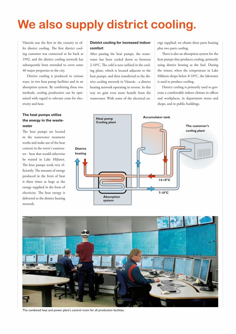
We also supply district cooling.Västerås was the first in the country to of-fer district cooling. The first district cool-ing customer was connected as far back as 1992, and the district cooling network has subsequently been extended to cover some 40 major properties in the city.
District cooling is produced in various ways: in two heat pump facilities and in an absorption system. By combining these two methods, cooling production can be opti-mised with regard to relevant costs for elec-tricity and heat.
The heat pumps utilise
the energy in the waste-
water
The heat pumps are located in the wastewater treatment works and make use of the heat content in the town's wastewa-ter - heat that would otherwise be wasted in Lake Mälaren. The heat pumps work very ef-ficiently. The amount of energy produced in the form of heat is three times as large as the energy supplied in the form of electricity. The heat energy is delivered to the district heating network.
District cooling for increased indoor
comfort
After passing the heat pumps, the waste-water has been cooled down to between 2-10°C. The cold is now utilised in the cool-ing plant, which is located adjacent to the heat pumps, and then transferred to the dis-trict cooling network in Västerås - a district heating network operating in reverse. In this way we gain even more benefit from the wastewater. With some of the electrical en-
ergy supplied, we obtain three parts heating plus two parts cooling.
There is also an absorption system for the heat pumps that produces cooling, primarily using district heating as the fuel. During the winter, when the temperature in Lake Mälaren drops below 8-10°C, the lakewater is used to produce cooling.
District cooling is primarily used to gen-erate a comfortable indoor climate in offices and workplaces, in department stores and shops, and in public buildings.
14-18°C
heat pumpCooling plant
accumulator tank
The customer's
cooling plant
7-10°Cabsorption system
District
heating
The combined heat and power plant's control room for all production facilities.
Wood chips 27 %

Mälarenergi ABBox 14721 03 VästeråsCorp. reg. no. 556448-9150Tel.:021-39 50 00Customer centre:021-39 50 50E-mail:[email protected] service:www.malarenergi.seVisiting address:Combined Heat and Power PlantSjöhagsvägen 23-27, VästeråsMälarenergi's head officeSjöhagsvägen 3, Västerås
Prod
uktio
n: R
CB2
AB
| Mic
hael
Hje
lt A
B.