a closed loop tbsc compensator for direct online starting ... · motor 1 induction motor 2...
TRANSCRIPT

Abstract-Topology for direct online starting of Induction
Motors (I.M.s) using Thyristor Binary Switched Capacitor (TBSC) compensator operating in closed loop is presented. TBSC is based on a chain of Thyristor Switched Capacitor (TSC) banks arranged in binary sequential manner. A transient free switching of TBSCs is carried out. Proposed topology allows switching in/out of capacitor banks according to the reactive power requirement of induction motors in very fast responding closed loop. Simulation results show that the proposed scheme can achieve reactive power compensation in cycle to cycle basis. Proposed scheme can be used for direct online starting of I.M.s with voltage sag mitigation at starting, which helps improving stability of the system and Power Factor (P.F.) improvement in steady state.
Keywords — Reactive power compensation, TBSC, transient free switching, voltage sag, Power Factor
I. INTRODUCTION
NDUCTION motors (I.M.) constitute a large portion of power system. Three-phase induction motors
represent the most significant load in the industrial plants, over the half of the delivered electrical energy [1]. Starting of induction motor may cause a problem of voltage sag in the power system. The IEEE defines voltage sag as: A decrease to between 0.1 and 0.9 p.u. in rms voltage or current at the power frequency for durations of 0.5 cycle to 1 min [2]. An induction motor at rest can be modeled as a transformer with the secondary winding short circuited. Thus when full voltage is applied, a heavy inrush current (of 6 to 10 times the rated value) is drawn from the power system that causes voltage sag. As the motor accelerates and attains the rated speed, the inrush current decays and the system voltage recovers [3]. Voltage sag can cause mal-operation of voltage sensitive devices such as computers,
Manuscript received July3rd, 2013; revised August 01, 2013. This work was supported in part by the Electrical Engineering Department of Walchand College of Engineering, Sangli. It is supported under Technical Quality Improvement Program (TEQIP_II
Irfan I Mujawaris a PG scholor with Electrical Engineering Department of Walchand College of Engineering, Sangli, [email protected]
Swapnil D Patil is a PG scholor with AnnasahebDange College of Endineering, Ashta, Maharashtra India [email protected]
Prof. Dr.U. Gudaru is with AnnasahebDange College of Endineering, Ashta, Maharashtra India. [email protected]
Dr. D.R.Patil is Prof. & Head of Department Walchand College of Engineering, Sangli, India. [email protected].
relays, programmable logic controllers etc. [chetan]. Also because of the highly inductive nature of the motor circuit at rest, the power factor is very low, usually of the order of 10 to 20 percent [3]. Thus reactive power demand at the starting of I.M. is very high and it reduces as motor picks up the speed. There are several solutions to minimize this problem, the most common are [5]: reactor start, auto transformer start, delta-wye start, capacitor start, soft starter, frequency variable driver (FVD) etc. All these methods except capacitor start are based on a motor terminal voltage reduction to decrease the rotor current, reducing the line voltage drop [5]. Problem with this method of starting is that the motor torque is directly proportional to the square of the supply voltage hence decrease in the motor terminal voltage will cause the motor torque to decrease, which may be insufficient for driving the required load [6]. Soft starter and frequency variable driver methods are the most expensive and complex, requiring more expert maintenance [7]. In capacitor start system, reactive current required by the motor during acceleration is supplied by capacitors which reduce the source current. This in turn reduces the magnitude of voltage sag in the system. Capacitor start method has a lower cost in comparison with other methods however one has to consider the transitory effects of switching of capacitor banks [3]. An alternative solution without motor terminal voltage reduction was proposed using Static VAR Compensator (SVC) in [8]. In [9] different topology of SVC without using thyristor controlled reactor (TCR) was proposed which has advantage of reduction in both cost as well as harmonics produced by TCR. This paper presents a simple topology, which is shown in Fig.1.
InductionMotor 1
InductionMotor 2
InductionMotor nTBSC
Compensation
Vs
Fig.1 Proposed Topology
A Closed Loop TBSC Compensator for Direct Online Starting of Induction Motors With
Voltage Sag Mitigation
Irfan IMujawar, Swapnil D Patil, U. Gudaru,Senior Member IEEE, D. R. Patil Member,IAENG
I
Proceedings of the World Congress on Engineering and Computer Science 2013 Vol I WCECS 2013, 23-25 October, 2013, San Francisco, USA
ISBN: 978-988-19252-3-7 ISSN: 2078-0958 (Print); ISSN: 2078-0966 (Online)
WCECS 2013
CONTROLLER
Point Of Common Coupling (PCC)
DistributionTransformer
P.T
V
I
C.T-Current TransformerP.T-Potential TransformerTBSC-Thyristor BinarySwitch CapacitorC-Capacitor Value
Induction Motor
8 TBSC Banks
22c20c 21c
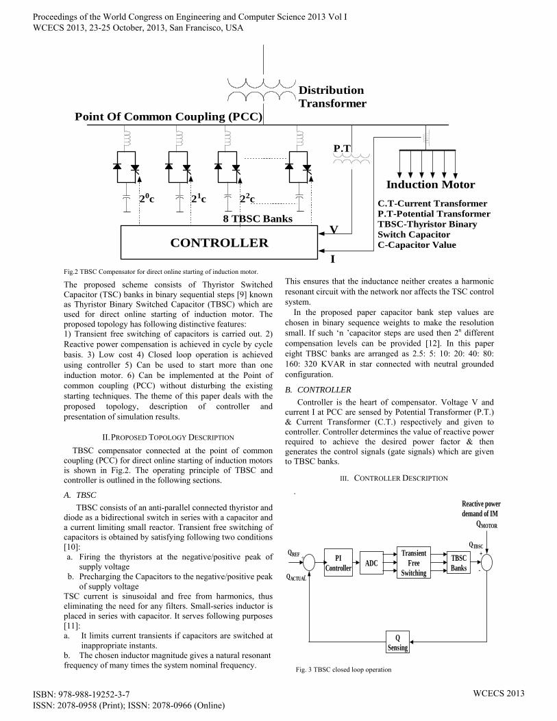
Fig.2 TBSC Compensator for direct online starting of induction motor.
The proposed scheme consists of Thyristor Switched Capacitor (TSC) banks in binary sequential steps [9] known as Thyristor Binary Switched Capacitor (TBSC) which are used for direct online starting of induction motor. The proposed topology has following distinctive features: 1) Transient free switching of capacitors is carried out. 2) Reactive power compensation is achieved in cycle by cycle basis. 3) Low cost 4) Closed loop operation is achieved using controller 5) Can be used to start more than one induction motor. 6) Can be implemented at the Point of common coupling (PCC) without disturbing the existing starting techniques. The theme of this paper deals with the proposed topology, description of controller and presentation of simulation results.
II. PROPOSED TOPOLOGY DESCRIPTION TBSC compensator connected at the point of common
coupling (PCC) for direct online starting of induction motors is shown in Fig.2. The operating principle of TBSC and controller is outlined in the following sections.
A. TBSC TBSC consists of an anti-parallel connected thyristor and
diode as a bidirectional switch in series with a capacitor and a current limiting small reactor. Transient free switching of capacitors is obtained by satisfying following two conditions [10]: a. Firing the thyristors at the negative/positive peak of
supply voltage b. Precharging the Capacitors to the negative/positive peak
of supply voltage TSC current is sinusoidal and free from harmonics, thus eliminating the need for any filters. Small-series inductor is placed in series with capacitor. It serves following purposes [11]: a. It limits current transients if capacitors are switched at
inappropriate instants. b. The chosen inductor magnitude gives a natural resonant frequency of many times the system nominal frequency.
This ensures that the inductance neither creates a harmonic resonant circuit with the network nor affects the TSC control system.
In the proposed paper capacitor bank step values are chosen in binary sequence weights to make the resolution small. If such ‘n ’capacitor steps are used then 2n different compensation levels can be provided [12]. In this paper eight TBSC banks are arranged as 2.5: 5: 10: 20: 40: 80: 160: 320 KVAR in star connected with neutral grounded configuration.
B. CONTROLLER Controller is the heart of compensator. Voltage V and
current I at PCC are sensed by Potential Transformer (P.T.) & Current Transformer (C.T.) respectively and given to controller. Controller determines the value of reactive power required to achieve the desired power factor & then generates the control signals (gate signals) which are given to TBSC banks.
III. CONTROLLER DESCRIPTION .
PIController ADC
QSensing
TransientFree
Switching
TBSCBanks
QTBSC
-
++
-
QREF
QACTUAL
Reactive powerdemand of IM
QMOTOR
Fig. 3 TBSC closed loop operation
Proceedings of the World Congress on Engineering and Computer Science 2013 Vol I WCECS 2013, 23-25 October, 2013, San Francisco, USA
ISBN: 978-988-19252-3-7 ISSN: 2078-0958 (Print); ISSN: 2078-0966 (Online)
WCECS 2013

A block diagram of TBSC compensator operating in
closed loop is shown in Fig. 3. Reference reactive power, QRefis calculated from the desired power factor (If unity power factor is required then Qref will be set to zero). Actual reactive power at PCC, QActual depends on the number of motors switched in the system. QActual is calculated by sensing voltage and current at PCC by P.T. and C.T. respectively. Error signal between QRef and QActual is given to PI controller. Discrete PI controller is used. Output of PI controller is given to ADC and its output is given to TBSC banks in such a way that no transients occur. Switching in/out of capacitor banks is decided by the controller. At the time of starting of I.M.s reactive power demand is large hence higher capacitor banks will be switched in while as motor reaches the rated speed only few lower capacitor banks will remain connected at the PCC. In this way closed loop operation of TBSC banks for direct online starting of I.M.s is achieved.
SIMULATION RESULTS MATLAB/SIMULINK software is used in the paper for
simulation. Data used in the simulation is shown below.
a. Source - Voltage V = 400 V, Rs = 0.0287Ω, Ls = 0.20471mH
b. Induction motor (I.M.) – 3 identical I.M.s are used in the simulation which are switched on at t = 0 sec, 0.8 sec and 1.6 sec respectively. For Simulation purpose at 1.6 sec, two 50 h.p. motors are switched on simultaneously to get 100 h.p. load. Parameters of each I.M. are shown in Table I TABLE I. PARAMETERS OF INDUCTION MOTOR
Sr. No. Parameter Values
1. Voltage (line-line) 400 V
2. Frequency 50 Hz
3. Nominal power 50 h.p.
4. Speed 1480 r.p.m.
TABLE II. VALUES OF EIGHT TBSC BANKS
Sr. No.
Q (in KVAR)
C (in µF)
L (in mH)
1. 2.5 50 0.10775
2. 5 100 0.0538
3. 10 200 0.0269
4. 20 400 0.0134
5. 40 800 0.0067
6. 80 1600 0.0033
7. 160 3200 0.0016
8. 320 6400 0.00084
.
c. TBSC banks - Eight TBSC banks are used in the simulation whose values are shown in Table II.
A Direct online induction motor starting without TBSC compensator
. Fig. 4 shows the waveform of motor line voltage.When
I.M.1 is switched on at t=0sec, the motor line voltage drops to 351V i.e. voltage sag of 11.14% takes place. Line voltage returns to steady value of 395V in 0.5sec.When I.M.2 is switched on at t=0.8sec, the motor line voltage drops to 349V i.e. voltage sag of 11.64% takes place. Line voltage returns to steady value of 392V in 0.5sec. When I.M.3 is switched on at t=1.6sec, the motor line voltage drops to 309V i.e. voltage sag of 21.77% takes place. Line voltage returns to steady value of 382V in 0.7sec
Fig. 5 shows the variation of reactive power with time. When I.M.1 & 2 is switched on at t= 0sec and 0.8sec respectively, reactive power demand is around 250 KVAR at starting period. Reactive power demand is around 380 KVAR when I.M.3 is switched on at t=1.6 sec. It is seen that reactive power demand is very high at the time of starting of motor and it reduces as the motor reaches the steady state condition. Because of high reactive power requirement at start voltage drops as shown in Fig. 4.
Proceedings of the World Congress on Engineering and Computer Science 2013 Vol I WCECS 2013, 23-25 October, 2013, San Francisco, USA
ISBN: 978-988-19252-3-7 ISSN: 2078-0958 (Print); ISSN: 2078-0966 (Online)
WCECS 2013

Fig. 4 Motor Line Voltage without TBSC compensator
Fig.5 Reactive Power variation of I.M. without TBSC compensator
Fig.6 Motor line current without TBSC compensator
Proceedings of the World Congress on Engineering and Computer Science 2013 Vol I WCECS 2013, 23-25 October, 2013, San Francisco, USA
ISBN: 978-988-19252-3-7 ISSN: 2078-0958 (Print); ISSN: 2078-0966 (Online)
WCECS 2013

Fig.7 Speed of motors without TBSC compensator
Fig. 6 shows the variation of motor current with time. When I.M.1 & 2 is switched on at t= 0sec and 0.8 sec respectively, current is around 500 A at starting period while at the time of starting of I.M. 3 it is around 1000 A. It is seen that when motor is switched on, current is very large at the starting period & it reduces as motor attains steady speed. Fig. 7 shows the variation of motor speed with time. When
I.M.1 is switched on at t= 0sec it achieves rated speed in 0.6 sec. I.M.2 is switched on at t=0.8 sec and it achieves rated speed in 0.6 sec. At the time of switching of I.M.2 speed of I.M.1 drops to 1460 rpm for very short duration of about one cycle. I.M.3 is switched on at t=1.6 sec and it achieves rated speed in 0.8 sec. At the time of switching of I.M.3 speed of I.M.1 & I.M.2 drops to 1442 rpm for very short duration of about one cycle.
B. Direct online induction motor starting with TBSC compensator
Discrete PI controller with KP = 0.54 & KI = 25 is used. 8 bit ADC is used in simulation. Waveforms of I.M. reactive power demand QMotor and reactive power given by TBSC QTBSC are shown in Fig. 8. From simulation results it is seen that QTBSC closely follows QMotor and actual reactive power QActual at PCC is approximately zero at all times. Thus power factor is maintained near unity at all time. The small error is due to the binary switching arrangement of TSCs. The first part of Fig.8 shows the instantaneous reactive
power required at the starting of three different Induction motors sequentially. While in the next part of the figure instantaneous reactive power supplied by TBSC is shown. The error between these two power is negligible. Fig. 9 shows the motor line voltage with TBSC compensator. When I.M.1 is switched on at t=0sec, motor line voltage drops to 389V i.e. small voltage sag of 2.01% takes place
for a duration of 0.4sec. Line voltage returns to steady value of 400V in 0.4sec. When I.M.2 is switched on at t=0.8sec, the motor line voltage drops to 377V i.e. voltage sag of 5.3% takes place for a duration of 0.4 sec. steady value of 396V in 0.4sec. When I.M.3 is switched on at t=1.6sec, the motor line voltage drops to 360V i.e. voltage sag of 7.92% takes place for a duration of 0.65 sec. Line voltage returns to steady value of 391V in 0.7sec.
These results show that with TBSC compensator there is improvement in the voltage profile. Fig. 10 shows the comparison of motor line voltage with and without TBSC compensator Current waveforms through all TSC banks & total compensating current (of R phase) are shown in Fig. 11 which are free from harmonics and have negligibly small transients only at few switching instants.
Fig. 12 shows the waveforms of motor current, total compensating current and source current. From these results it is clear that the total compensating current i.e. current flowing through all TBSC banks is almost equal to the motor current. Source current at the instant of switching of I.M.1 and I.M.2 (i.e. at t=0 sec and t= 0.8 sec) is around 300 A. While at the instant of switching of I.M.3 is around 700 A. These results show that with TBSC compensator there is considerable reduction in source current magnitude. This leads to reduction in voltage sag as shown in Fig. 10.
Fig. 13 shows the variation of motor speed with time. When I.M.1 is switched on at t=0sec it achieves rated speed in 0.5 sec. I.M.2 is switched on at t=0.8 sec and it achieves rated speed in 0.5 sec. At the time of switching of I.M.2 speed of I.M.1 drops to 1460 rpm for very short duration of about one cycle. I.M.3 is switched on at t=1.6 sec and it achieves rated speed in 0.6 sec. At the time of switching of I.M.3 speed of I.M.1 & I.M.2 drops to 1442 rpm for very short duration of about one cycle. Comparisons of results with & without TBSC Compensator are shown in Table III
Proceedings of the World Congress on Engineering and Computer Science 2013 Vol I WCECS 2013, 23-25 October, 2013, San Francisco, USA
ISBN: 978-988-19252-3-7 ISSN: 2078-0958 (Print); ISSN: 2078-0966 (Online)
WCECS 2013

Fig.8 Waveforms of QMotorand QTBSC
Fig. 9 Motor Line Voltage with TBSC compensator
Proceedings of the World Congress on Engineering and Computer Science 2013 Vol I WCECS 2013, 23-25 October, 2013, San Francisco, USA
ISBN: 978-988-19252-3-7 ISSN: 2078-0958 (Print); ISSN: 2078-0966 (Online)
WCECS 2013

Fig. 10 Motor Line Voltage without TBSC compensator (Top) and with TBSC compensator (Bottom)
.
Fig. 11 Current Waveforms through all TSC banks and total compensating current (of R phase only)……cntinued
Proceedings of the World Congress on Engineering and Computer Science 2013 Vol I WCECS 2013, 23-25 October, 2013, San Francisco, USA
ISBN: 978-988-19252-3-7 ISSN: 2078-0958 (Print); ISSN: 2078-0966 (Online)
WCECS 2013

Fig. 11 Current Waveforms through all TSC banks and total compensating current (of R phase only)
Fig. 12 Simulation results showing waveforms of motor current, total compensating current and source current in A (of R phase only)
Fig.13 Simulation results showing speed of Motors with TBSC compensator
Proceedings of the World Congress on Engineering and Computer Science 2013 Vol I WCECS 2013, 23-25 October, 2013, San Francisco, USA
ISBN: 978-988-19252-3-7 ISSN: 2078-0958 (Print); ISSN: 2078-0966 (Online)
WCECS 2013
Table III : Comparison Results with and without TBSC
Sr. No. Parameter
Without TBSC Compensator
With TBSC Compensator
I.M.1
(50 h.p.)
I.M.2 (50
h.p.)
I.M.3 (100 h.p.)
I.M.1 (50
h.p.)
I.M.2 (50
h.p.)
I.M.3 (100 h.p.)
1 Switching instant (in
sec) 0.0 0.8 1.6 0.0 0.8 1.6
2 % Voltage sag
11.14 11.64 21.77 2.01 5.3 7.92
3
Reactive power at
starting (in KVAR)
250 250 380 Closely matches with the required value
4 Starting
current (in A)
500 500 1000 300 300 700
IV CONCLUSION A topology for direct online starting of induction motors
using TBSC compensator is presented. TSC bank step values are chosen in binary sequence weights to make the resolution small in order to achieve almost stepless reactive power compensation. Harmonic contents in source current are negligibly small. With the use of TBSC compensator; voltage sag magnitude gets reduced as well as voltage profile is improved. Controller operates in a closed loop to determine the number of capacitor units to be switched in the system. At the time of starting of I.M.s higher capacitor banks are switched in the system while once the motor reaches the rated speed only few lower capacitor banks will remain connected at the PCC. Thus at all times power factor is maintained near unity. The proposed scheme is effective during both steady state and transient conditions. Separate starting method for individual induction motors can be avoided and many motors can be started direct online using the proposed scheme as long as TBSC banks are capable of supplying the required reactive power demand.
REFERENCES [1] D.G.Walters, “The repair of low tension induction motors — Best
practices to maintain energy efficiency” - IEE Half-Day Colloquium on Refurbishment of Machines, May 1998.
[2] IEEE Std 1159-1995, IEEE recommended practice for monitoring electric power quality.
[3] Stout, John H. “Capacitor Starting of Large Motors” – Industry Applications, IEEE Transactions on volume IA-14, Issue 3, May 1978.
[4] J.Douglas,“Solving problems of power quality,”EPRI Journal, vol.18, no.8,pp 6-15, Dec.1993.
[5] Eben-ezer Prates da Silveira, Robson Celso Pires, Antonio Tadeu Lyrio de Almeida, Angelo José , Junqueira Rezek, “Direct on line starting induction motor with thyristor switched capacitor based voltage regulation”, IEEE pp.1124-1129, 2009.
[6] Tarek El-Shennawy, Mahmoud El-Gammal, Amr Abou-Ghazala, Abdel Monem Moussa, “Mitigation of Voltage Sags in a Refinery with Induction Motors” vol.36, No.1, pp.118-131, 2009.
[7] Farr, L.B.; Farr, T.A. “Considerations in medium voltage reduced voltage motor starting the good, the bad and the ugly - petroleum and
Chemical Industry Technical Conference, 2007. PCIC '07. IEEE 17-19 Sept. 2007.
[8] Osborn, D.; Richins, R. “Voltage regulation system during large motor starting and operation” - Cement Industry Technical Conference, 1999. Conference Record. 1999 IEEE-IAS/PCA 11-15 April 1999.
[9] C. Maffrand, J. W. Dixon, and L. Morán, “Binary controlled, static VAR compensator, based on electronically switched capacitors,” in Proc. IEEE PESC’98, pp.1392–1396, 1998.
[10] Juan Dixon, Luis Morán, José Rodríguez, Ricardo Domke, “Reactive power compensation technologies, state of–the-art review”,Proc. IEEE, vol. 93, no. 12, pp.2144-2164, 2005.
[11] R.Mohan Mathur and Rajiv K. Varma, Thyristor-based FACTS controllers for electrical transmission systems, a John Wiley & sons, Inc. Publication, 2002, pp.47–82.
[12] U. Gudaru and D. R. Patil, “An Innovative Transient Free Adaptive SVC in Stepless Mode of Control”, World Academy of Science Engineering and Technology 77 pp.200–207, 2011.
IrfanIsakMujawar has obtained his B.E. (Electrical) in first class with distinction in 2009 from Walchand College of Engg. Sangli (India). Currently he is persuing his M.Tech (Electrical, Power System ) degree in the same institute under the guidance of Prof. D. R. Patil. His areas of interest include FACTS, Power Electronics and Power Quality
D.R.Patil aged 57 has obtained his B.E. (Electrical) in first class in 1981,
M.E. (Electrical) in first class in 1985 and Ph.D. in 2012 from Shivaji University, Kolhapur. He started his teaching career from 1985, as a lecturer in Electrical department of Walchand College of Engineering, Sangli (India). Subsequently in 1993 he promoted as a assistant professor of control systems on the post graduate. He has been actively associated with teaching various subjects of control systems as well as power systems at post graduate levels. He has guided almost 70 dissertation / project at post
graduate level and about 30 projects at under graduate levels. He has about 20 international conference and 15 national conference / seminars publications. He conducted 3 workshops and 3 training programs in the institute. Also, he has attended 12 summer / winter schools. His areas of interest are control systems applicable to power systems.
Swapnil D. Patilaged 23 has obtained his B.E. inElectrical Engineering with First Class in 2013 from Shivaji University, Kolhapur (MS). Currently he is perusing his post graduation from ADCET Ashta. His areas of interest are Power System, FACTS and Power Quality.
U. Gudaru, aged 73 years has obtained his B.E. in 1962, M.E. in 1966 and Ph.D in 1983. He published three papers at International level, and presented / published 32 other papers at National seminars / Journals. After superannuation in 1999, the All India Council for Technical Education (AICTE) has awarded Emeritus Fellowship for carrying out research work on the topic, “Measures for Power
Quality Improvement”. The author is a Fellow of Institution of Engineers (India) in their Computer Engineering Division. He is a member of IEEE in their power engineering society since 2000
Proceedings of the World Congress on Engineering and Computer Science 2013 Vol I WCECS 2013, 23-25 October, 2013, San Francisco, USA
ISBN: 978-988-19252-3-7 ISSN: 2078-0958 (Print); ISSN: 2078-0966 (Online)
WCECS 2013