a build your own open source cnc lathe...
TRANSCRIPT

A Build-Your-Own
Open Source CNC Lathe Machine
Fabrication and User manual
MHRD – Teaching Learning Centre for Design and Manufacturing
Indian Institute of Information Technology for Design and Manufacturing –
Kancheepuram, Chennai - 600127
A Build-Your-Own Open Source CNC Lathe Machine
August 14, 2017
Documentation Author
Rakesh Nair
Project Team
Raja Ganapathi S.
Rakesh Nair
Kamal Prasath Balaji
Guide
Dr. Shunmugham R. Pandian
For information:
Teaching Learning Center for Design and Manufacturing(TLC),
IIITDM Kancheepuram,
Melakottaiyur Village, Chennai 600127
E-mail: [email protected]
Website: www.tlc.iiitdm.ac.in

Table of Contents
1. Introduction …………………………………………………………………1
1.1 CNC…………………………………………………………………1
1.2 Lathe machine ………………………………………………………4
2. CNC Lathe fabrication……………………………………………………... 6
2.1 Design……………………………………………………………….6
2.1 Parts…………………………………………………………………6
2.2 Fabrication procedure……………………………………………….9
3. Associated software…………………………………………………...……17
3.1 CAD software……………………………………………………....17
3.3 Grbl GRU………………………………………………………......17
3.4 Universal G-Code sender……………………………………….….18
3.5 Grbl…………………………………………………………………18
4. Operating Procedure……….…………………………………………….…19
5. Sample Experiments……………………………………………..…………27
5.1 Simple Facing and Turning…………………………...……………27
5.2 Step Turning………………………………………………………..32
5.3 Taper Turning………………………………………………………39
5.4 Step and Taper Turning…………………………………………….46
6. Conclusion………………………………………………………………….53
Appendix I – Design Sheets
Appendix II – Product Datasheets
Appendix III – Bill of Materials and Part Suppliers

1
1. INTRODUCTION
Industrial revolution that had led to the emergence of modern era has its roots in the Lathe
machine. Widely known as the ‘Mother of machine tools’, Lathe works by removing materials
from a workpiece to give a desired shape and size. Various material removing operations such
as facing, turning, chamfering, knurling, grooving etc can be performed with it. In the past,
mechanized power generated by water wheels and steam engines was used to operate lathe,
imparting a certain degree of control to it. But it’s not until the 1950s that servomechanisms
were applied to the control, coupling with the computers to yield Computer Numerical Control
(CNC) lathe. Today CNC lathe machines are being used in almost all manufacturing industries.
1.1 Computer Numerical Control (CNC)
Computer Numerical Control or CNC refers to the automation of machine tools by using
computers executing pre-programmed sequence of machine control commands.
A simple CNC system
Taking digitized data fed into it by the user, a computer and CAD/CAM (Computer Aided
Design / Computer Aided Manufacturing) program is used to control, automate and monitor
the movement of the machine. The machine can be a lathe, milling machine, router, welder,
grinder, laser or waterjet cutter. CNC controller works with a series of motors and drive
components to move and control the machine axes, executing programmed motions.
1.1.1 Parts
1.1.1.1 Computer system and CAD/CAM
All modern CNC machines constitute a computer system with a CAD/CAM software into
which the user can feed in the CAD diagram or directly enter a set of commands called NC
code for the machine to understand.
2
1.1.1.2 Numerical Control or NC Code
Originally developed to program parts directly at the machine keyboard without any CAM
software, the Numerical Control (NC) codes tell the machine what moves to execute, one by
one, as well as controlling other machining functions like spindle speed, feed rate. The most
commonly used language is G-code or ISO code, a simple alphanumeric programming
language developed for early CNC machines. Instead, if a CAD diagram is fed, the
postprocessor in the program converts the diagram to the relevant NC code and pass it to the
Control Unit.
1.1.1.3 Control Unit
The control unit constitutes a controller, drives and circuitry for machine motion along multiple
axes, atleast two (X and Y), in the case of CNC lathe machine while a third axis (Z) can be
used to move the tool spindle as in the case of CNC milling machine. Stepper motors are used
for accurate control of the machining process resulting in high quality, accurate finishing.
1.1.2 Types of control
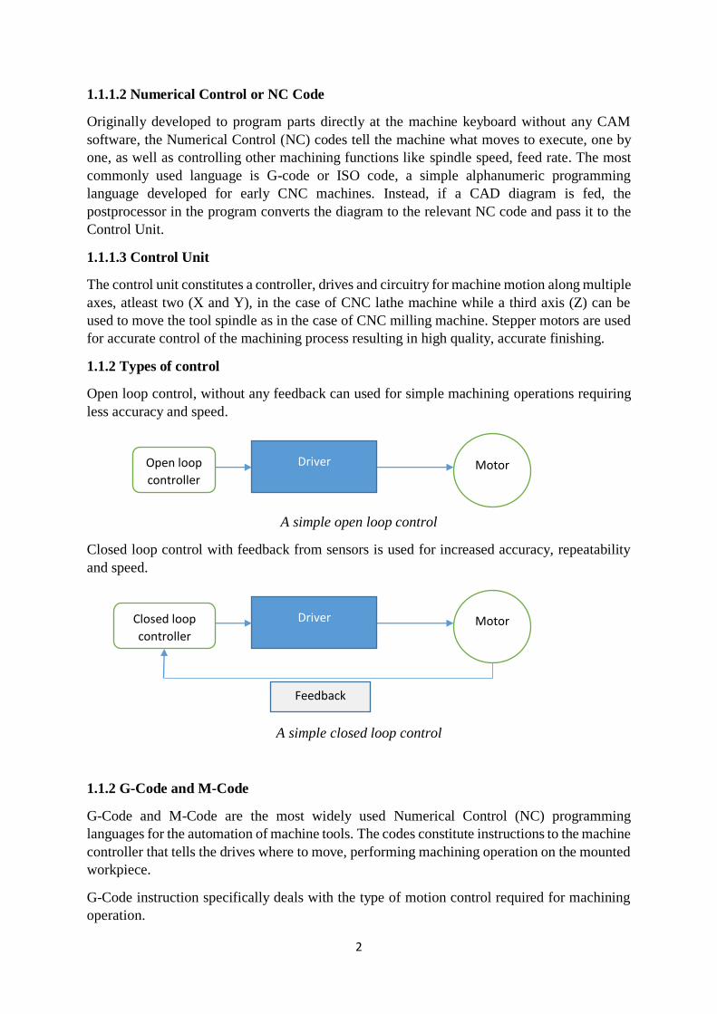
Open loop control, without any feedback can used for simple machining operations requiring
less accuracy and speed.
A simple open loop control
Closed loop control with feedback from sensors is used for increased accuracy, repeatability
and speed.
A simple closed loop control
1.1.2 G-Code and M-Code
G-Code and M-Code are the most widely used Numerical Control (NC) programming
languages for the automation of machine tools. The codes constitute instructions to the machine
controller that tells the drives where to move, performing machining operation on the mounted
workpiece.
G-Code instruction specifically deals with the type of motion control required for machining
operation.
Open loop
controller
Driver Motor
Closed loop
controller
Driver Motor
Feedback
3
M-Code deals with machine functions like coolant control, spindle control,
List of G-Code, M-Code instructions:
G00 - Positioning at rapid speed; Milling and Turning
G01 - Linear interpolation (machining a straight line); Milling and Turning
G02 - Circular interpolation clockwise (machining arcs); Milling and Turning
G03 - Circular interpolation, counter clockwise; Milling and Turning
G04 - Milling and Turning, Dwell
G09 - Milling and Turning, Exact stop
G10 - Setting offsets in the program; Milling and Turning
G12 - Circular pocket milling, clockwise; Milling
G13 - Circular pocket milling, counter clockwise; Milling
G17 - X-Y plane for arc machining; Milling and Turning with live tooling
G18 - Z-X plane for arc machining; Milling and Turning with live tooling
G19 - Z-Y plane for arc machining; Milling and Turning with live tooling
G20 - Inch units; Milling and Turning
G21 - Metric units; Milling and Turning
G27 - Reference return check; Milling and Turning
G28 - Automatic return through reference point; Milling and Turning
G29 - Move to location through reference point; Milling and Turning (slightly
different for each machine)
G31 - Skip function; Milling and Turning
G32 - Thread cutting; Turning
G33 - Thread cutting; Milling
G40 - Cancel diameter offset; Milling. Cancel tool nose offset; Turning
G41 - Cutter compensation left; Milling. Tool nose radius compensation left; Turning
G42 - Cutter compensation right; Milling. Tool nose radius compensation right;
Turning
G43 - Tool length compensation; Milling
G44 - Tool length compensation cancel; Milling (sometimes G49)
G50 - Set coordinate system and maximum RPM; Turning
G52 - Local coordinate system setting; Milling and Turning
G53 - Machine coordinate system setting; Milling and Turning
G54~G59 - Workpiece coordinate system settings #1 t0 #6; Milling and Turning
G61 - Exact stop check; Milling and Turning
G65 - Custom macro call; Milling and Turning
G70 - Finish cycle; Turning
G71 - Rough turning cycle; Turning
G72 - Rough facing cycle; Turning
G73 - Irregular rough turning cycle; Turning
G73 - Chip break drilling cycle; Milling
G74 - Left hand tapping; Milling
G74 - Face grooving or chip break drilling; Turning
G75 - OD groove pecking; Turning
G76 - Fine boring cycle; Milling
G76 - Threading cycle; Turning
G80 - Cancel cycles; Milling and Turning
G81 - Drill cycle; Milling and Turning
G82 - Drill cycle with dwell; Milling
G83 - Peck drilling cycle; Milling
G84 - Tapping cycle; Milling and Turning 6

4
G85 - Bore in, bore out; Milling and Turning
G86 - Bore in, rapid out; Milling and Turning G87 - Back boring cycle; Milling
G90 - Absolute programming
G91 - Incremental programming
G92 - Reposition origin point; Milling
G92 - Thread cutting cycle; Turning
G94 - Per minute feed; Milling
G95 - Per revolution feed; Milling
G96 - Constant surface speed control; Turning
G97 - Constant surface speed cancel
G98 - Per minute feed; Turning
G99 - Per revolution feed; Turning
M00 - Program stop; Milling and Turning
M01 - Optional program stop; Turning and Milling
M02 - Program end; Turning and Milling
M03 - Spindle on clockwise; Turning and Milling
M04 - Spindle on counter clockwise; Turning and Milling
M05 - Spindle off; Turning and Milling
M06 - Tool change; Milling
M08 - Coolant on; Turning and Milling
M09 - Coolant off; Turning and Milling
M10 - Chuck or rotary table clamp; Turning and Milling
M11 - Chuck or rotary table clamp off; Turning and Milling
M19 - Orient spindle; Turning and Milling
M30 - Program end, return to start; Turning and Milling
M97 - Local sub-routine call; Turning and Milling
M98 - Sub-program call; Turning and Milling
M99 - End of sub program; Turning and Milling
1.2 Lathe machine
Lathe is a machine tool that rotates the workpiece about an axis of rotation to perform various
operations like facing, turning, knurling, chamfering etc. using cutting tools to create objects
with symmetry about that axis.
Manual lathe machine

5
1.2.1 Parts of manual lathe machine
Main parts of manual lathe are as following;
1.2.1.1 Lathe Bed
The bed of the lathe machine is the base on which all other parts are mounted. It is horizontal,
massive and rigid single piece of casting made to support other active parts of the lathe.
Headstock and tailstock are located the two extremities of the bed. A guideway runs in between
holding the carriage for transverse axis. Generally, cast iron alloyed with nickel and chromium
material is used for manufacturing lathe bed.
1.2.1.2 Headstock
Head stock bears the horizontal axle parallel to the bed, called spindle. Spindles are often
hollow and have exterior threads for mounting work-holding accessories like chuck. Spindle is
driven by an electric motor via gearbox or belt to impart motion to the workpiece. In addition
to this, the headstock can also contain speed control methods for adjusting the spindle speed as
the machining requirement.
1.2.1.3 Carriage
The carriage runs on the guideway along the working length of the lathe. It carries the cross
slide, saddle, compound rest and tool post for the transverse movement and machining. It can
be adjusted to fit any angle for machining operation. The compound rest is actuated by a screw,
which rotates a nut fixed to the saddle. Tool post mounts the tool holder.
1.2.1.4 Tailstock
The tail stock is commonly used for the objective of primarily giving an outer bearing and
support the circular job being turned on centres. Tail stock can be easily set or adjusted for
alignment or non-alignment with respect to the spindle centre and carries a centre called dead
centre for supporting one end of the work. Both live and dead centres have 60° conical points
to fit centre holes in the circular job, the other end tapering to allow for good fitting into the
spindles. The dead centre can be mounted in ball bearing so that it rotates with the job avoiding
friction of the job with dead centre as it important to hold heavy jobs.
1.2.1.5. Feed Mechanism
Feed mechanism is the combination of different units through which motion of headstock
spindle is transmitted to the carriage of lathe machine.
The gearing at the end of bed transmits the rotary motion of headstock spindle to the feed
gear box. Through the feed gear box the motion is further transmitted either to the feed shaft
or lead screw, depending on whether the lathe machine is being used for plain turning or screw
cutting. The feed gear box contains a number of different sizes of gears. The feed gear box
provides a means to alter the rate of feed, and the ration between revolutions of the headstock
spindle and the movement of carriage for thread cutting by changing the speed of rotation of
the feed rod or lead screw. The apron is fitted to the saddle. It contains gears and clutches to
transmit motion from the feed rod to the carriage, and the half nut which engages with the lead
screw during cutting threads.

6
2. CNC LATHE FABRICATION
2.1 Design
The main design requirements of the CNC lathe include machining accuracy, rigidity and
compactness. Wood was chosen as the primary material for the CNC lathe for its sturdiness,
low weight, easy machinability and low cost. To attain compactness, easy usage and light
weight, the machine has been designed to be table top type.
CNC Lathe design
2.2 Parts of CNC Lathe
Hardware parts of the machine are combined with fabricated as well as few commercially
available products. Main frame of the machine is constructed using wood blocks of 1”and 3
“size, as per design. Design file of each component is attached in Appendix I. Following table
contains list of components required for CNC Lathe machine construction.
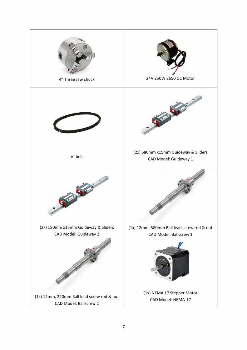
Table 1. Parts List
Parts List
Wooden blocks – 1”, 3”
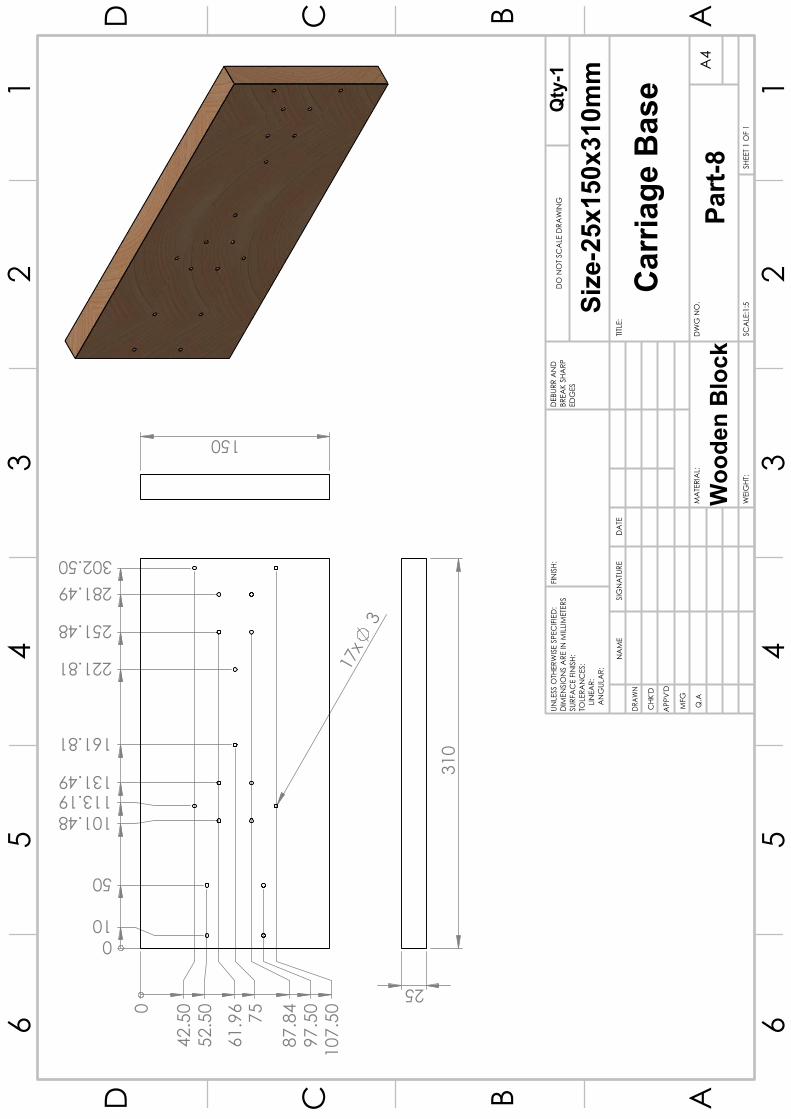
CAD Model – Base Wooden block
Headstock frame
CAD Model – Headstock Setup
7
4” Three Jaw chuck
24V 250W 2650 DC Motor
V- belt
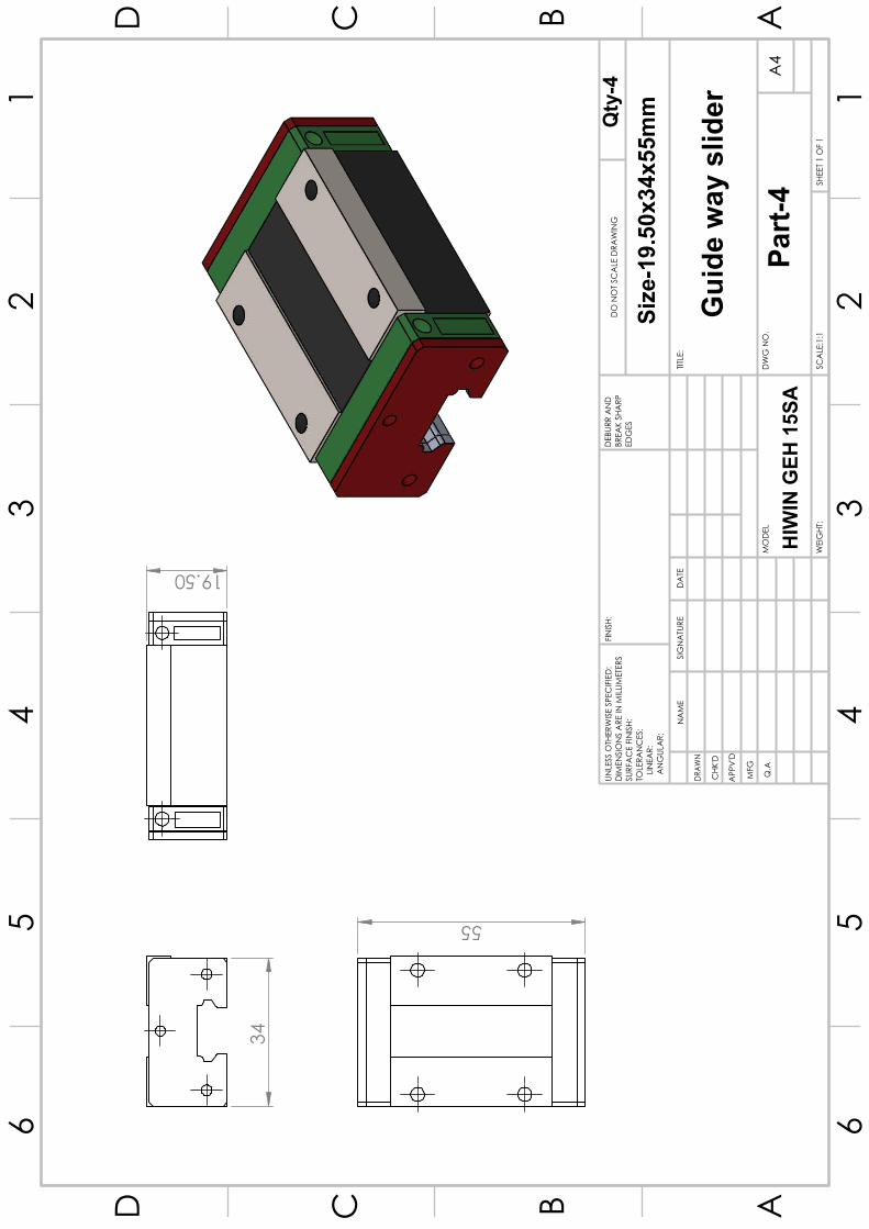
(2x) 680mm x15mm Guideway & Sliders
CAD Model: Guideway 1
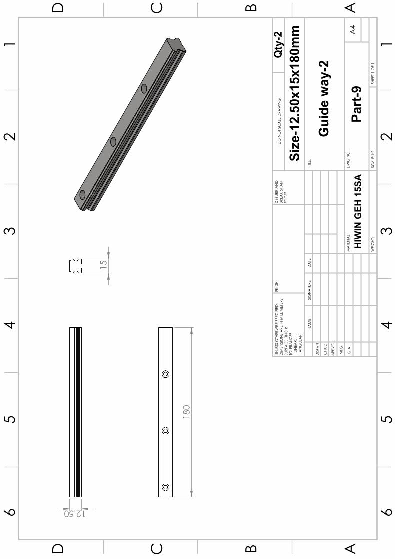
(2x) 180mm x15mm Guideway & Sliders
CAD Model: Guideway 2
(1x) 12mm, 580mm Ball lead screw rod & nut
CAD Model: Ballscrew 1
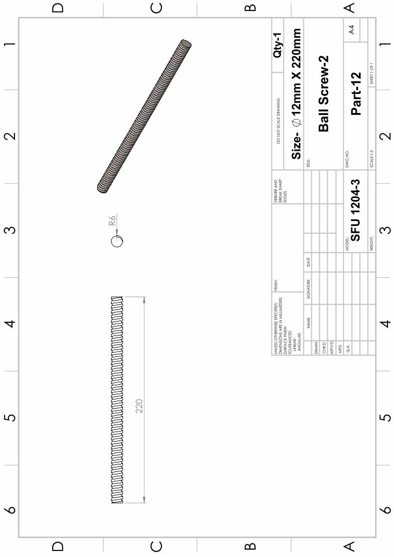
(1x) 12mm, 220mm Ball lead screw rod & nut
CAD Model: Ballscrew 2
(1x) NEMA 17 Stepper Motor
CAD Model: NEMA-17
8
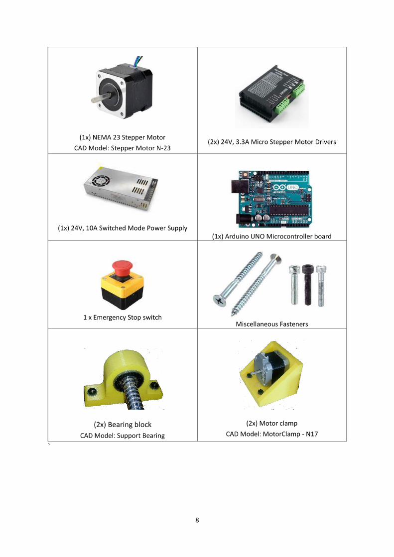
(1x) NEMA 23 Stepper Motor
CAD Model: Stepper Motor N-23
(2x) 24V, 3.3A Micro Stepper Motor Drivers
(1x) 24V, 10A Switched Mode Power Supply
(1x) Arduino UNO Microcontroller board
1 x Emergency Stop switch
Miscellaneous Fasteners
(2x) Bearing block
CAD Model: Support Bearing
(2x) Motor clamp
CAD Model: MotorClamp - N17
`
9
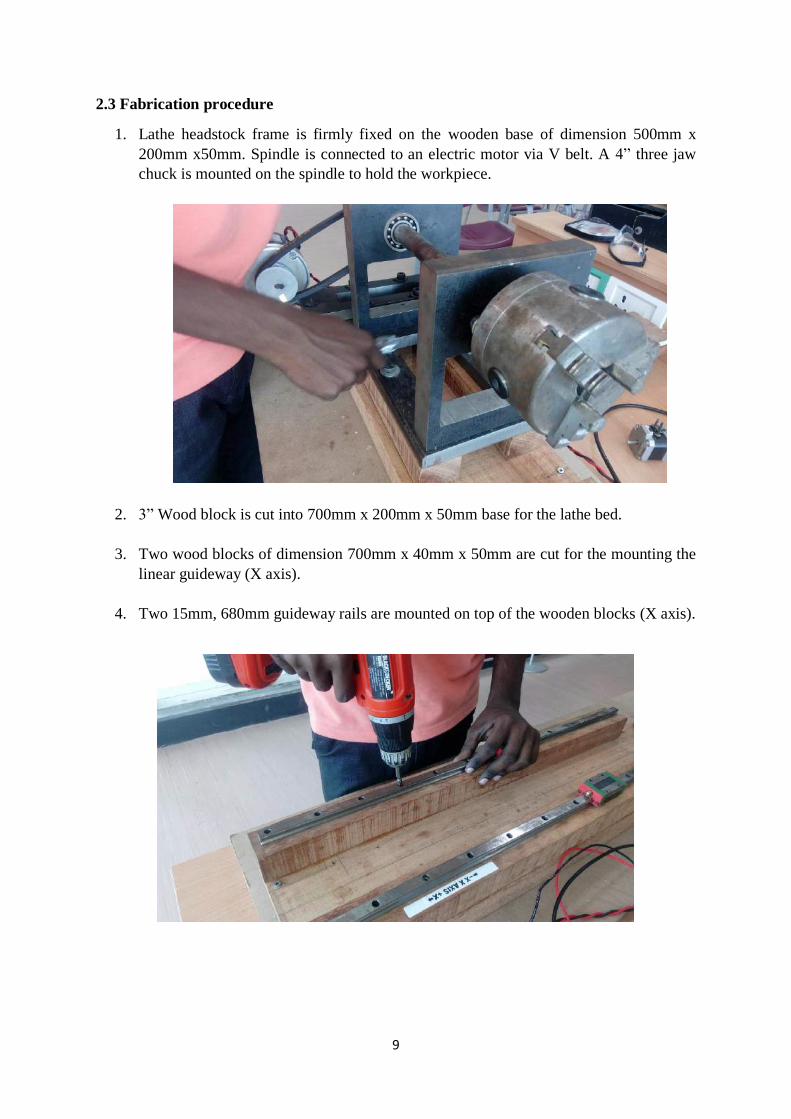
2.3 Fabrication procedure
1. Lathe headstock frame is firmly fixed on the wooden base of dimension 500mm x
200mm x50mm. Spindle is connected to an electric motor via V belt. A 4” three jaw
chuck is mounted on the spindle to hold the workpiece.
2. 3” Wood block is cut into 700mm x 200mm x 50mm base for the lathe bed.
3. Two wood blocks of dimension 700mm x 40mm x 50mm are cut for the mounting the
linear guideway (X axis).
4. Two 15mm, 680mm guideway rails are mounted on top of the wooden blocks (X axis).

10
5. NEMA 23 stepper motor is fixed to the motor clamp.
6. The motor is fixed in between the guideways.
7. Rigid coupler is attached to the motor shaft.

11
8. Bearing blocks are fixed at both ends to mount the ball lead screw.
9. A protrusion block of dimension 80mm x 55mm x 20mm is attached to the base of the
carriage to be fixed to the ball lead screw nut.
10. A ball lead screw of diameter 12mm and length 580mm is fixed in between the guideway
blocks with a bearing block and NEMA 23 stepper motor.
12
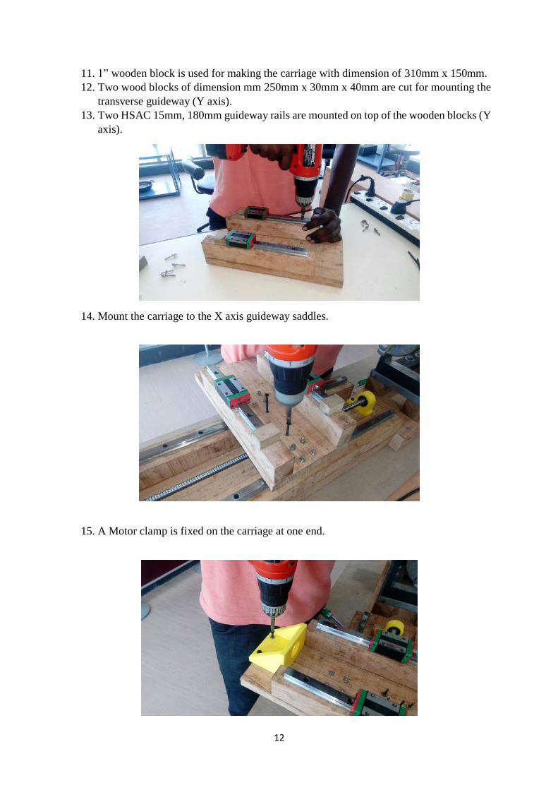
11. 1” wooden block is used for making the carriage with dimension of 310mm x 150mm.
12. Two wood blocks of dimension mm 250mm x 30mm x 40mm are cut for mounting the
transverse guideway (Y axis).
13. Two HSAC 15mm, 180mm guideway rails are mounted on top of the wooden blocks (Y
axis).
14. Mount the carriage to the X axis guideway saddles.
15. A Motor clamp is fixed on the carriage at one end.
13
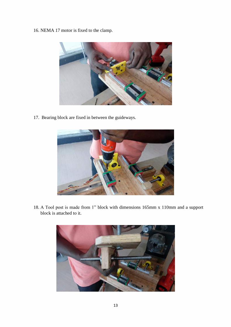
16. NEMA 17 motor is fixed to the clamp.
17. Bearing block are fixed in between the guideways.
18. A Tool post is made from 1” block with dimensions 165mm x 110mm and a support
block is attached to it.
14
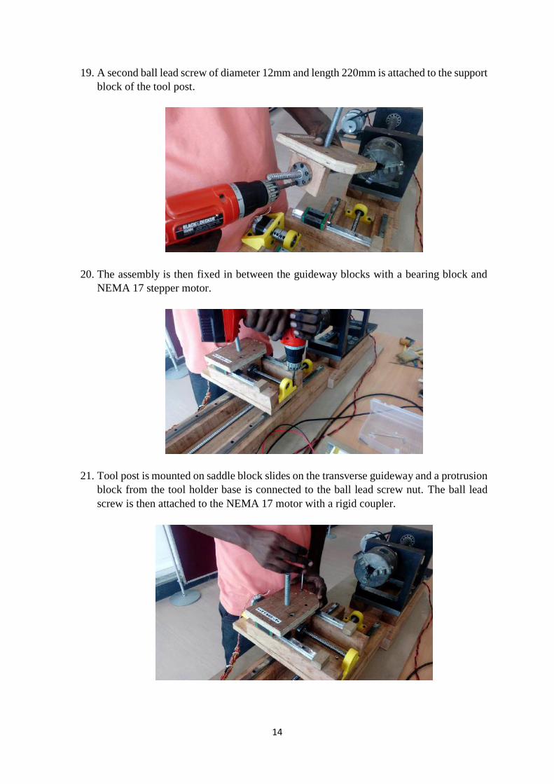
19. A second ball lead screw of diameter 12mm and length 220mm is attached to the support
block of the tool post.
20. The assembly is then fixed in between the guideway blocks with a bearing block and
NEMA 17 stepper motor.
21. Tool post is mounted on saddle block slides on the transverse guideway and a protrusion
block from the tool holder base is connected to the ball lead screw nut. The ball lead
screw is then attached to the NEMA 17 motor with a rigid coupler.
15
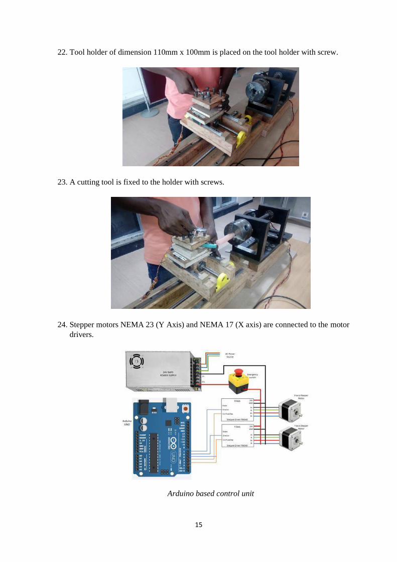
22. Tool holder of dimension 110mm x 100mm is placed on the tool holder with screw.
23. A cutting tool is fixed to the holder with screws.
24. Stepper motors NEMA 23 (Y Axis) and NEMA 17 (X axis) are connected to the motor
drivers.
Arduino based control unit
16
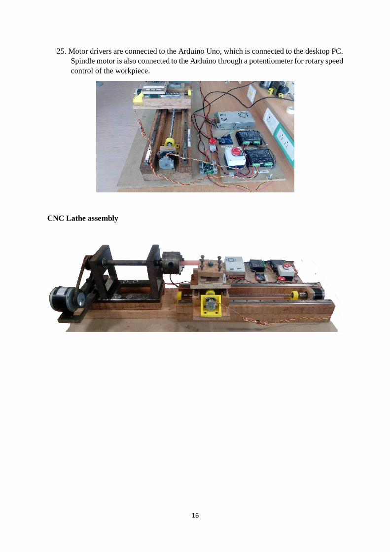
25. Motor drivers are connected to the Arduino Uno, which is connected to the desktop PC.
Spindle motor is also connected to the Arduino through a potentiometer for rotary speed
control of the workpiece.
CNC Lathe assembly
17
2. ASSOCIATED SOFTWARE
3.1 CAD software - AutoCAD Student version
AutoCAD is a computer aided design and drafting software application with 2D, 3D design
and documentation, drawings.
AutoCAD Student version is a fully comprehensive 3D CAD application that you can
download and install for free.
You can download the student version of AutoCAD from the following link:-
https://www.autodesk.com/education/free-software/autocad
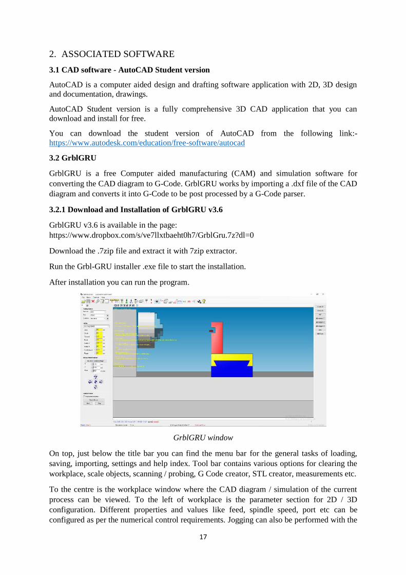
3.2 GrblGRU
GrblGRU is a free Computer aided manufacturing (CAM) and simulation software for
converting the CAD diagram to G-Code. GrblGRU works by importing a .dxf file of the CAD
diagram and converts it into G-Code to be post processed by a G-Code parser.
3.2.1 Download and Installation of GrblGRU v3.6
GrblGRU v3.6 is available in the page:
https://www.dropbox.com/s/ve7llxtbaeht0h7/GrblGru.7z?dl=0
Download the .7zip file and extract it with 7zip extractor.
Run the Grbl-GRU installer .exe file to start the installation.
After installation you can run the program.
GrblGRU window
On top, just below the title bar you can find the menu bar for the general tasks of loading,
saving, importing, settings and help index. Tool bar contains various options for clearing the
workplace, scale objects, scanning / probing, G Code creator, STL creator, measurements etc.
To the centre is the workplace window where the CAD diagram / simulation of the current
process can be viewed. To the left of workplace is the parameter section for 2D / 3D
configuration. Different properties and values like feed, spindle speed, port etc can be
configured as per the numerical control requirements. Jogging can also be performed with the

18
directional buttons provided. To the right is the preset diagrams for quick access and
simulation.
3.3 Universal G-Code sender
Universal G-Code sender is a Java based Grbl compatible cross platform G-Code sender used
to run Grbl controlled CNC machines. It is used to send the NC code generated into the Grbl
program in Arduino for CNC machining.
Universal G-Code sender also contains controls to directly jog the tool for accurate positioning
before CNC machining and visualizing window to see the real time machining in progress.
3.4 Grbl G-Code parser
Grbl is an open source, embedded, high performance, G-Code parser and CNC controller writer
in optimized C that will run on Arduino. It is a high performance, low cost alternative to parallel
port based motion control for CNC machines. Running primarily on Atmega 323
microcontroller, Grbl maintains upto 30kHz of stable, jitter free control pulses and can achieve
precise timing and asynchronous operation.
It accepts standards-compliant G-Code and has been tested with output of several CAM tool
with no problems. Grbl also includes full acceleration management with look ahead in which
the controller will look up to 18 motions into the future and plan its velocities ahead to deliver
smooth acceleration and jerk free cornering. Compiled version of GRBL software is available
in the form of hex file and is burned into the Arduino. Grbl CNC code will receive signals from
Arduino’s seriel buffer and parses it to decode the serial data into G code. Grbl settings in
Arduino will be stored in the EEPROM of Arduino and so when configured will not erased
during power off. Settings can also be viewed and modified anytime by sending corresponding
configuration characters. $$ symbol is used as configuration character from which we can view
different settings of the machine, such as axis feed rate, steps/mm, software limits, axis
acceleration values and resolution of movement.
3.2.1 Download and installation of Grbl
Grbl is available in the GitHub site: https://github.com/grbl/grbl
Download the zip format and extract the bundle. Inside you will find a list of build files, header
files and examples for Arduino.

19
4. OPERATING PROCEDURE
1. Draw one half of the symmetrical part to be machined in AutoCAD (Student version) CAD
software.
2. Export the CAD diagram in .dxf format.
20
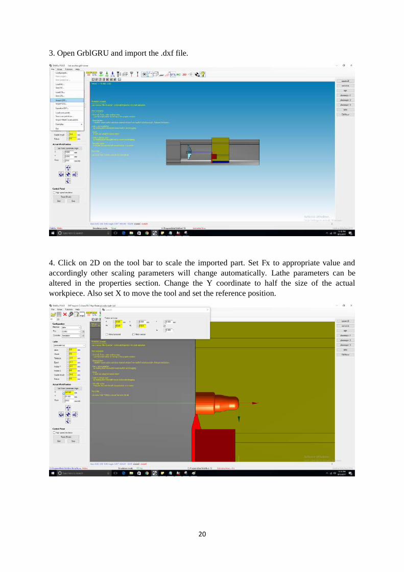
3. Open GrblGRU and import the .dxf file.
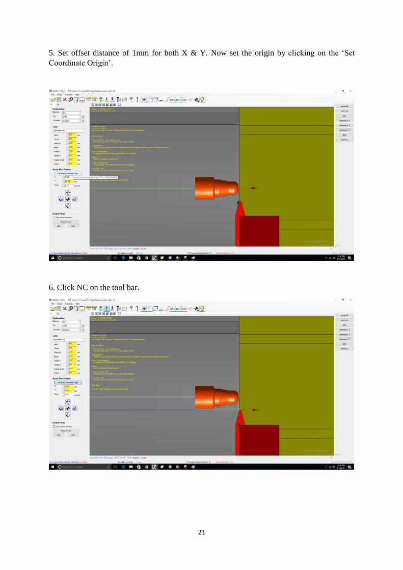
4. Click on 2D on the tool bar to scale the imported part. Set Fx to appropriate value and
accordingly other scaling parameters will change automatically. Lathe parameters can be
altered in the properties section. Change the Y coordinate to half the size of the actual
workpiece. Also set X to move the tool and set the reference position.
21
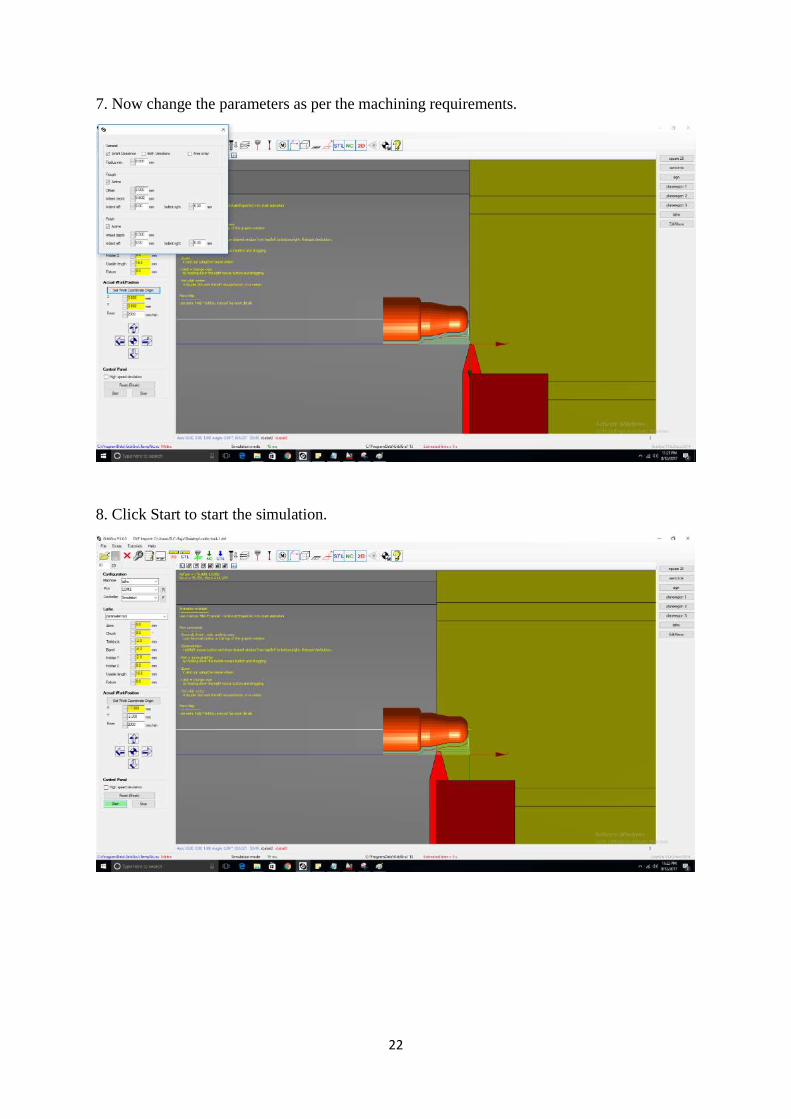
5. Set offset distance of 1mm for both X & Y. Now set the origin by clicking on the ‘Set
Coordinate Origin’.
6. Click NC on the tool bar.
22
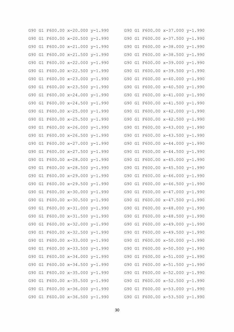
7. Now change the parameters as per the machining requirements.
8. Click Start to start the simulation.

23
9. Select File and Save NC with .nc extension to export the file.
10. Open Universal GCode Sender and set COM port for Arduino.

24
11. Use the virtual control panel to manually move the tool to 1mm in X & Y for origin
reference as per the NC code.
12. Click on ‘machine control’ and reset zero in X & Y.

25
13. Select file mode ad browse open the NC file previously saved.
14. Click ‘Send’ to transfer the code to Grbl in the Arduino that controls the CNC Lathe.
Visualize button on the right can be used for real-time machining simulation.

26
15. CNC Lathe will automatically machine the workpiece as per the CAD diagram input by the
user. You can see the machining visualization by clicking on the ‘Visualize’ button on top right
side.
16. Wood and wax workpiece can be machined to the required shape.

27
5. SAMPLE EXPERIMENTS
5.1 Experiment 1 – Simple Facing and Turning using CNC Lathe
Aim: To machine the given work piece according to the dimensions given in diagram using
CNC Lathe
Tools required:
Chuck key
Tool post spanner/ Hex key
Turning tool
Chamfering tool
Vernier Calliper
Steel rule
Power supply
Software required:
GrblGru V.3.7.0
Arduino 1.8.1
Universal G-Code sender
Procedure:
1. The work piece is held in the lathe chuck.
2. The cutting tool is held in the tool post and its cutting point is set to lathe axis using
reference from the open source software.
3. Import the drawing in. stl /.nc/.dxf into the software
4. Make sure the drawn piece is imported within the specific parameters. Otherwise
Resize the workpiece into appropriate dimensions.
5. Fix the feed cut parameters and tolerance level and fix the tool piece at the centre.
6. Once the outer diameter of the piece is set we can start simulating the feed cut
machining
7. Save the simulated piece by converting it into G-code using the G-code creator
button.
8. After the G code is generated, switch on the power source and start rotating the chuck
and spindle setup. (make sure that the tool post is set to pre-set origin before
commencement of running the code)
9. Commence the transmission of code into the universal G-code sender and start the
process by pressing the send button.
10. Automatically according to the code produced in the system, the carriage is moved on
the bed and is clamped at the required position.
11. By giving cross feed the tool is fed parallel to lathe axis.
12. The facing operation of the work piece is machined to required dimensions.
13. The system by repeating the same procedure, the next face of work piece is machined.
14. Then the tool is automatically fed parallel to lathe axis with suitable depth of cut. (can
be done manually)
15. The finished piece is retrieved.

28
Result:
The given work piece is machined according to required dimensions by the CNC lathe
according to the code given by the universal G-code Sender.
Diagram:
Part Diagram in modelling software
Simulation and generation of G-Code in GrblGRU
Materials supplied: Machinable Wax Ø23mm x 50mm
Tool material: High Speed Steel

29
Generated Code:
; Created by
GrblGru:GCodeCreator
; 25.03.2017 11:56:16
; Finfeed= 800
; F= 1500
; Fmax= 2000
; OffsetX = 0
; DeltaY = 1
; Smart clearance = True
; Free entry = False
; Both directions = True
; Finfeed Finish = 400
; F Finish = 600
; Fmax Finish= 2000
; DeltaY Finish = 2
G90 G1 F1000
; Rough 21
; Move to startpoint
G90 G1 F2000.00 y0.000
F2000.00 x0.000
; Back to startpoint
G90 G1 F2000.00 y0.000
F2000.00 x0.000
; Finish
G90 G1 F600.00 x0.000 y-2.989
G90 G1 F600.00 x-0.500 y-2.663
G90 G1 F600.00 x-1.000 y-2.337
G90 G1 F600.00 x-1.500 y-2.012
G90 G1 F600.00 x-2.000 y-1.990
G90 G1 F600.00 x-2.500 y-1.990
G90 G1 F600.00 x-3.000 y-1.990
G90 G1 F600.00 x-3.500 y-1.990
G90 G1 F600.00 x-4.000 y-1.990
G90 G1 F600.00 x-4.500 y-1.990
G90 G1 F600.00 x-5.000 y-1.990
G90 G1 F600.00 x-5.500 y-1.990
G90 G1 F600.00 x-6.000 y-1.990
G90 G1 F600.00 x-6.500 y-1.990
G90 G1 F600.00 x-7.000 y-1.990
G90 G1 F600.00 x-7.500 y-1.990
G90 G1 F600.00 x-8.000 y-1.990
G90 G1 F600.00 x-8.500 y-1.990
G90 G1 F600.00 x-9.000 y-1.990
G90 G1 F600.00 x-9.500 y-1.990
G90 G1 F600.00 x-10.000 y-1.990
G90 G1 F600.00 x-10.500 y-1.990
G90 G1 F600.00 x-11.000 y-1.990
G90 G1 F600.00 x-11.500 y-1.990
G90 G1 F600.00 x-12.000 y-1.990
G90 G1 F600.00 x-12.500 y-1.990
G90 G1 F600.00 x-13.000 y-1.990
G90 G1 F600.00 x-13.500 y-1.990
G90 G1 F600.00 x-14.000 y-1.990
G90 G1 F600.00 x-14.500 y-1.990
G90 G1 F600.00 x-15.000 y-1.990
G90 G1 F600.00 x-15.500 y-1.990
G90 G1 F600.00 x-16.000 y-1.990
G90 G1 F600.00 x-16.500 y-1.990
G90 G1 F600.00 x-17.000 y-1.990
G90 G1 F600.00 x-17.500 y-1.990
G90 G1 F600.00 x-18.000 y-1.990
G90 G1 F600.00 x-18.500 y-1.990
G90 G1 F600.00 x-19.000 y-1.990
G90 G1 F600.00 x-19.500 y-1.990
30
G90 G1 F600.00 x-20.000 y-1.990
G90 G1 F600.00 x-20.500 y-1.990
G90 G1 F600.00 x-21.000 y-1.990
G90 G1 F600.00 x-21.500 y-1.990
G90 G1 F600.00 x-22.000 y-1.990
G90 G1 F600.00 x-22.500 y-1.990
G90 G1 F600.00 x-23.000 y-1.990
G90 G1 F600.00 x-23.500 y-1.990
G90 G1 F600.00 x-24.000 y-1.990
G90 G1 F600.00 x-24.500 y-1.990
G90 G1 F600.00 x-25.000 y-1.990
G90 G1 F600.00 x-25.500 y-1.990
G90 G1 F600.00 x-26.000 y-1.990
G90 G1 F600.00 x-26.500 y-1.990
G90 G1 F600.00 x-27.000 y-1.990
G90 G1 F600.00 x-27.500 y-1.990
G90 G1 F600.00 x-28.000 y-1.990
G90 G1 F600.00 x-28.500 y-1.990
G90 G1 F600.00 x-29.000 y-1.990
G90 G1 F600.00 x-29.500 y-1.990
G90 G1 F600.00 x-30.000 y-1.990
G90 G1 F600.00 x-30.500 y-1.990
G90 G1 F600.00 x-31.000 y-1.990
G90 G1 F600.00 x-31.500 y-1.990
G90 G1 F600.00 x-32.000 y-1.990
G90 G1 F600.00 x-32.500 y-1.990
G90 G1 F600.00 x-33.000 y-1.990
G90 G1 F600.00 x-33.500 y-1.990
G90 G1 F600.00 x-34.000 y-1.990
G90 G1 F600.00 x-34.500 y-1.990
G90 G1 F600.00 x-35.000 y-1.990
G90 G1 F600.00 x-35.500 y-1.990
G90 G1 F600.00 x-36.000 y-1.990
G90 G1 F600.00 x-36.500 y-1.990
G90 G1 F600.00 x-37.000 y-1.990
G90 G1 F600.00 x-37.500 y-1.990
G90 G1 F600.00 x-38.000 y-1.990
G90 G1 F600.00 x-38.500 y-1.990
G90 G1 F600.00 x-39.000 y-1.990
G90 G1 F600.00 x-39.500 y-1.990
G90 G1 F600.00 x-40.000 y-1.990
G90 G1 F600.00 x-40.500 y-1.990
G90 G1 F600.00 x-41.000 y-1.990
G90 G1 F600.00 x-41.500 y-1.990
G90 G1 F600.00 x-42.000 y-1.990
G90 G1 F600.00 x-42.500 y-1.990
G90 G1 F600.00 x-43.000 y-1.990
G90 G1 F600.00 x-43.500 y-1.990
G90 G1 F600.00 x-44.000 y-1.990
G90 G1 F600.00 x-44.500 y-1.990
G90 G1 F600.00 x-45.000 y-1.990
G90 G1 F600.00 x-45.500 y-1.990
G90 G1 F600.00 x-46.000 y-1.990
G90 G1 F600.00 x-46.500 y-1.990
G90 G1 F600.00 x-47.000 y-1.990
G90 G1 F600.00 x-47.500 y-1.990
G90 G1 F600.00 x-48.000 y-1.990
G90 G1 F600.00 x-48.500 y-1.990
G90 G1 F600.00 x-49.000 y-1.990
G90 G1 F600.00 x-49.500 y-1.990
G90 G1 F600.00 x-50.000 y-1.990
G90 G1 F600.00 x-50.500 y-1.990
G90 G1 F600.00 x-51.000 y-1.990
G90 G1 F600.00 x-51.500 y-1.990
G90 G1 F600.00 x-52.000 y-1.990
G90 G1 F600.00 x-52.500 y-1.990
G90 G1 F600.00 x-53.000 y-1.990
G90 G1 F600.00 x-53.500 y-1.990

31
G90 G1 F600.00 x-54.000 y-1.990
G90 G1 F600.00 x-54.500 y-1.990
G90 G1 F600.00 x-55.000 y-1.990
G90 G1 F600.00 x-55.500 y-1.990
G90 G1 F600.00 x-56.000 y-1.990
G90 G1 F600.00 x-56.500 y-1.990
G90 G1 F600.00 x-57.000 y-1.990
G90 G1 F600.00 x-57.500 y-1.990
G90 G1 F600.00 x-58.000 y-1.990
G90 G1 F600.00 x-58.500 y-1.990
G90 G1 F600.00 x-59.000 y-1.990
G90 G1 F600.00 x-59.500 y-1.990
G90 G1 F600.00 x-60.000 y-1.990
G90 G1 F600.00 x-60.500 y-1.990
G90 G1 F600.00 x-61.000 y-1.990
G90 G1 F600.00 x-61.500 y-1.990
G90 G1 F600.00 x-62.000 y-1.990
G90 G1 F600.00 x-62.500 y-1.990
G90 G1 F600.00 x-63.000 y-1.990
G90 G1 F600.00 x-63.500 y-1.990
G90 G1 F600.00 x-64.000 y-1.990
G90 G1 F600.00 x-64.500 y-1.990
G90 G1 F600.00 x-65.000 y-1.990
G90 G1 F600.00 x-65.500 y-1.990
G90 G1 F600.00 x-66.000 y-1.990
G90 G1 F600.00 x-66.500 y-1.990
G90 G1 F600.00 x-67.000 y-1.990
G90 G1 F600.00 x-67.500 y-1.990
G90 G1 F600.00 x-68.000 y-1.990
G90 G1 F600.00 x-68.500 y-1.990
G90 G1 F600.00 x-69.000 y-1.990
G90 G1 F600.00 x-69.500 y-1.990
G90 G1 F600.00 x-70.000 y-1.990
G90 G1 F600.00 x-70.500 y-1.990
G90 G1 F600.00 x-71.000 y-1.990
G90 G1 F600.00 x-71.500 y-1.990
G90 G1 F600.00 x-72.000 y-1.990
G90 G1 F600.00 x-72.500 y-1.990
G90 G1 F600.00 x-73.000 y-1.990
G90 G1 F600.00 x-73.500 y-1.990
G90 G1 F600.00 x-74.000 y-1.990
G90 G1 F600.00 x-74.500 y-1.990
G90 G1 F600.00 x-75.000 y-1.990
G90 G1 F600.00 x-75.500 y-1.990
G90 G1 F600.00 x-76.000 y-1.990
G90 G1 F600.00 x-76.500 y-1.990
G90 G1 F600.00 x-77.000 y-1.990
G90 G1 F600.00 x-77.500 y-1.990
; Back to startpoint
G90 G1 F2000.00 y0.000
F2000.00 x0.000
32
5.2 Experiment 2 – Step Turning using CNC Lathe
Aim: To machine the given work piece according to the dimensions given in diagram using
CNC Lathe
Tools required:
Chuck key
Tool post spanner/ Hex key
Turning tool
Chamfering tool
Vernier Calliper
Steel rule
Power supply
Software required:
GrblGru V.3.7.0
Arduino 1.8.1
Universal G-Code sender
Procedure:
1. The work piece is held in the lathe chuck.
2. The cutting tool is held in the tool post and its cutting point is set to lathe axis using
reference from the open source software.
3. Import the drawing in. stl /.nc/.dxf into the software
4. Make sure the drawn piece is imported within the specific parameters. Otherwise
resize the work piece into appropriate dimensions.
5. Fix the feed cut parameters and tolerance level and fix the tool piece at the centre.
6. Once the outer diameter of the piece is set we can start simulating the feed cut
machining
7. Save the simulated piece by converting it into G-code using the G-code creator
button.
8. After the G code is generated, switch on the power source and start rotating the chuck
and spindle setup. (make sure that the tool post is set to pre-set origin before
commencement of running the code)
9. Commence the transmission of code into the universal G-code sender and start the
process by pressing the send button.
10. Automatically the facing and plain turning operation are carried out as per the given
dimensions.
11. After the plain turning operation is completed the tool is fed parallel to the lathe axis
to the particular length assigned by the code.
12. Two or more cuts are given accordingly to retrieve the required diameter.
13. Now the first step of machining is completed and by repeating the same process the
CNC lathe comenses its operation with the specified diameter.
14. By this time the work piece would be completed.
33
Result:
The given work piece is machined according to required dimensions by the CNC lathe
according to the code given by the universal G-code Sender
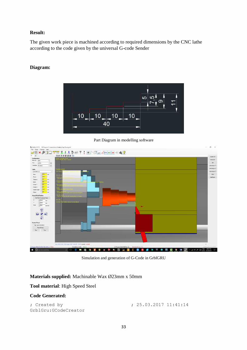
Diagram:
Part Diagram in modelling software
Simulation and generation of G-Code in GrblGRU
Materials supplied: Machinable Wax Ø23mm x 50mm
Tool material: High Speed Steel
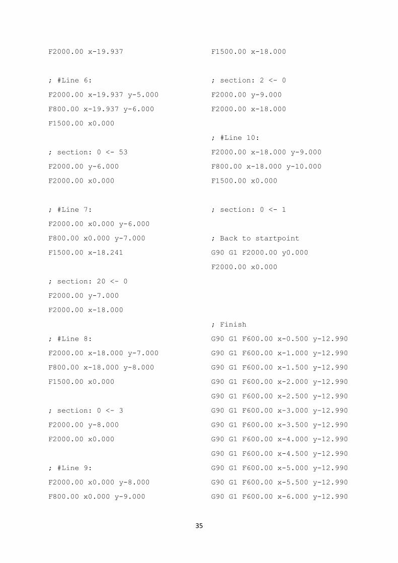
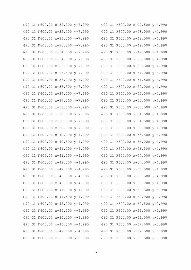
Code Generated:
; Created by
GrblGru:GCodeCreator
; 25.03.2017 11:41:14

34
; Finfeed= 800
; F= 1500
; Fmax= 2000
; OffsetX = 0
; DeltaY = 1
; Smart clearance = True
; Free entry = False
; Both directions = True
; Finfeed Finish = 400
; F Finish = 600
; Fmax Finish= 2000
; DeltaY Finish = 2
G90 G1 F1000
; Rough 161
; Move to startpoint
G90 G1 F2000.00 y0.000
F2000.00 x0.000
; #Line 1:
F2000.00 x0.000 y0.000
F800.00 x0.000 y-1.000
F1500.00 x-58.000
; section: 108 <- 0
F2000.00 y-1.000
F2000.00 x-58.000
; #Line 2:
F2000.00 x-58.000 y-1.000
F800.00 x-58.000 y-2.000
F1500.00 x0.000
; section: 0 <- 107
F2000.00 y-2.000
F2000.00 x0.000
; #Line 3:
F2000.00 x0.000 y-2.000
F800.00 x0.000 y-3.000
F1500.00 x-39.937
; section: 105 <- 0
F2000.00 y-3.000
F2000.00 x-38.241
; #Line 4:
F2000.00 x-38.241 y-3.000
F800.00 x-38.241 y-4.000
F1500.00 x0.000
; section: 0 <- 72
F2000.00 y-4.000
F2000.00 x0.000
; #Line 5:
F2000.00 x0.000 y-4.000
F800.00 x0.000 y-5.000
F1500.00 x-38.000
; section: 55 <- 0
F2000.00 y-5.000
35
F2000.00 x-19.937
; #Line 6:
F2000.00 x-19.937 y-5.000
F800.00 x-19.937 y-6.000
F1500.00 x0.000
; section: 0 <- 53
F2000.00 y-6.000
F2000.00 x0.000
; #Line 7:
F2000.00 x0.000 y-6.000
F800.00 x0.000 y-7.000
F1500.00 x-18.241
; section: 20 <- 0
F2000.00 y-7.000
F2000.00 x-18.000
; #Line 8:
F2000.00 x-18.000 y-7.000
F800.00 x-18.000 y-8.000
F1500.00 x0.000
; section: 0 <- 3
F2000.00 y-8.000
F2000.00 x0.000
; #Line 9:
F2000.00 x0.000 y-8.000
F800.00 x0.000 y-9.000
F1500.00 x-18.000
; section: 2 <- 0
F2000.00 y-9.000
F2000.00 x-18.000
; #Line 10:
F2000.00 x-18.000 y-9.000
F800.00 x-18.000 y-10.000
F1500.00 x0.000
; section: 0 <- 1
; Back to startpoint
G90 G1 F2000.00 y0.000
F2000.00 x0.000
; Finish
G90 G1 F600.00 x-0.500 y-12.990
G90 G1 F600.00 x-1.000 y-12.990
G90 G1 F600.00 x-1.500 y-12.990
G90 G1 F600.00 x-2.000 y-12.990
G90 G1 F600.00 x-2.500 y-12.990
G90 G1 F600.00 x-3.000 y-12.990
G90 G1 F600.00 x-3.500 y-12.990
G90 G1 F600.00 x-4.000 y-12.990
G90 G1 F600.00 x-4.500 y-12.990
G90 G1 F600.00 x-5.000 y-12.990
G90 G1 F600.00 x-5.500 y-12.990
G90 G1 F600.00 x-6.000 y-12.990

36
G90 G1 F600.00 x-6.500 y-12.990
G90 G1 F600.00 x-7.000 y-12.990
G90 G1 F600.00 x-7.500 y-12.990
G90 G1 F600.00 x-8.000 y-12.990
G90 G1 F600.00 x-8.500 y-12.990
G90 G1 F600.00 x-9.000 y-12.990
G90 G1 F600.00 x-9.500 y-12.990
G90 G1 F600.00 x-10.000 y-
12.990
G90 G1 F600.00 x-10.500 y-
12.990
G90 G1 F600.00 x-11.000 y-
12.990
G90 G1 F600.00 x-11.500 y-
12.990
G90 G1 F600.00 x-12.000 y-
12.990
G90 G1 F600.00 x-12.500 y-
12.990
G90 G1 F600.00 x-13.000 y-
12.990
G90 G1 F600.00 x-13.500 y-
12.990
G90 G1 F600.00 x-14.000 y-
12.990
G90 G1 F600.00 x-14.500 y-
12.990
G90 G1 F600.00 x-15.000 y-
12.990
G90 G1 F600.00 x-15.500 y-
12.990
G90 G1 F600.00 x-16.000 y-
12.990
G90 G1 F600.00 x-16.500 y-
12.990
G90 G1 F600.00 x-17.000 y-
12.990
G90 G1 F600.00 x-17.500 y-
12.990
G90 G1 F600.00 x-18.000 y-
12.990
G90 G1 F600.00 x-18.500 y-
12.990
G90 G1 F600.00 x-19.000 y-
12.990
G90 G1 F600.00 x-19.500 y-
12.990
G90 G1 F600.00 x-20.000 y-7.990
G90 G1 F600.00 x-20.500 y-7.990
G90 G1 F600.00 x-21.000 y-7.990
G90 G1 F600.00 x-21.500 y-7.990
G90 G1 F600.00 x-22.000 y-7.990
G90 G1 F600.00 x-22.500 y-7.990
G90 G1 F600.00 x-23.000 y-7.990
G90 G1 F600.00 x-23.500 y-7.990
G90 G1 F600.00 x-24.000 y-7.990
G90 G1 F600.00 x-24.500 y-7.990
G90 G1 F600.00 x-25.000 y-7.990
G90 G1 F600.00 x-25.500 y-7.990
G90 G1 F600.00 x-26.000 y-7.990
G90 G1 F600.00 x-26.500 y-7.990
G90 G1 F600.00 x-27.000 y-7.990
G90 G1 F600.00 x-27.500 y-7.990
G90 G1 F600.00 x-28.000 y-7.990
G90 G1 F600.00 x-28.500 y-7.990
G90 G1 F600.00 x-29.000 y-7.990
G90 G1 F600.00 x-29.500 y-7.990
G90 G1 F600.00 x-30.000 y-7.990
G90 G1 F600.00 x-30.500 y-7.990
G90 G1 F600.00 x-31.000 y-7.990
G90 G1 F600.00 x-31.500 y-7.990
37
G90 G1 F600.00 x-32.000 y-7.990
G90 G1 F600.00 x-32.500 y-7.990
G90 G1 F600.00 x-33.000 y-7.990
G90 G1 F600.00 x-33.500 y-7.990
G90 G1 F600.00 x-34.000 y-7.990
G90 G1 F600.00 x-34.500 y-7.990
G90 G1 F600.00 x-35.000 y-7.990
G90 G1 F600.00 x-35.500 y-7.990
G90 G1 F600.00 x-36.000 y-7.990
G90 G1 F600.00 x-36.500 y-7.990
G90 G1 F600.00 x-37.000 y-7.990
G90 G1 F600.00 x-37.500 y-7.990
G90 G1 F600.00 x-38.000 y-7.990
G90 G1 F600.00 x-38.500 y-7.990
G90 G1 F600.00 x-39.000 y-7.990
G90 G1 F600.00 x-39.500 y-7.990
G90 G1 F600.00 x-40.000 y-4.990
G90 G1 F600.00 x-40.500 y-4.990
G90 G1 F600.00 x-41.000 y-4.990
G90 G1 F600.00 x-41.500 y-4.990
G90 G1 F600.00 x-42.000 y-4.990
G90 G1 F600.00 x-42.500 y-4.990
G90 G1 F600.00 x-43.000 y-4.990
G90 G1 F600.00 x-43.500 y-4.990
G90 G1 F600.00 x-44.000 y-4.990
G90 G1 F600.00 x-44.500 y-4.990
G90 G1 F600.00 x-45.000 y-4.990
G90 G1 F600.00 x-45.500 y-4.990
G90 G1 F600.00 x-46.000 y-4.990
G90 G1 F600.00 x-46.500 y-4.990
G90 G1 F600.00 x-47.000 y-4.990
G90 G1 F600.00 x-47.500 y-4.990
G90 G1 F600.00 x-48.000 y-4.990
G90 G1 F600.00 x-48.500 y-4.990
G90 G1 F600.00 x-49.000 y-4.990
G90 G1 F600.00 x-49.500 y-4.990
G90 G1 F600.00 x-50.000 y-4.990
G90 G1 F600.00 x-50.500 y-4.990
G90 G1 F600.00 x-51.000 y-4.990
G90 G1 F600.00 x-51.500 y-4.990
G90 G1 F600.00 x-52.000 y-4.990
G90 G1 F600.00 x-52.500 y-4.990
G90 G1 F600.00 x-53.000 y-4.990
G90 G1 F600.00 x-53.500 y-4.990
G90 G1 F600.00 x-54.000 y-4.990
G90 G1 F600.00 x-54.500 y-4.990
G90 G1 F600.00 x-55.000 y-4.990
G90 G1 F600.00 x-55.500 y-4.990
G90 G1 F600.00 x-56.000 y-4.990
G90 G1 F600.00 x-56.500 y-4.990
G90 G1 F600.00 x-57.000 y-4.990
G90 G1 F600.00 x-57.500 y-4.990
G90 G1 F600.00 x-58.000 y-4.990
G90 G1 F600.00 x-58.500 y-4.990
G90 G1 F600.00 x-59.000 y-4.990
G90 G1 F600.00 x-59.500 y-4.990
G90 G1 F600.00 x-60.000 y-0.990
G90 G1 F600.00 x-60.500 y-0.990
G90 G1 F600.00 x-61.000 y-0.990
G90 G1 F600.00 x-61.500 y-0.990
G90 G1 F600.00 x-62.000 y-0.990
G90 G1 F600.00 x-62.500 y-0.990
G90 G1 F600.00 x-63.000 y-0.990 G90 G1 F600.00 x-63.500 y-0.990
38
G90 G1 F600.00 x-64.000 y-0.990
G90 G1 F600.00 x-64.500 y-0.990
G90 G1 F600.00 x-65.000 y-0.990
G90 G1 F600.00 x-65.500 y-0.990
G90 G1 F600.00 x-66.000 y-0.990
G90 G1 F600.00 x-66.500 y-0.990
G90 G1 F600.00 x-67.000 y-0.990
G90 G1 F600.00 x-67.500 y-0.990
G90 G1 F600.00 x-68.000 y-0.990
G90 G1 F600.00 x-68.500 y-0.990
G90 G1 F600.00 x-69.000 y-0.990
G90 G1 F600.00 x-69.500 y-0.990
G90 G1 F600.00 x-70.000 y-0.990
G90 G1 F600.00 x-70.500 y-0.990
G90 G1 F600.00 x-71.000 y-0.990
G90 G1 F600.00 x-71.500 y-0.990
G90 G1 F600.00 x-72.000 y-0.990
G90 G1 F600.00 x-72.500 y-0.990
G90 G1 F600.00 x-73.000 y-0.990
G90 G1 F600.00 x-73.500 y-0.990
G90 G1 F600.00 x-74.000 y-0.990
G90 G1 F600.00 x-74.500 y-0.990
G90 G1 F600.00 x-75.000 y-0.990
G90 G1 F600.00 x-75.500 y-0.990
G90 G1 F600.00 x-76.000 y-0.990
G90 G1 F600.00 x-76.500 y-0.990
G90 G1 F600.00 x-77.000 y-0.990
G90 G1 F600.00 x-77.500 y-0.990
G90 G1 F600.00 x-78.000 y-0.990
G90 G1 F600.00 x-78.500 y-0.990
G90 G1 F600.00 x-79.000 y-0.990
G90 G1 F600.00 x-79.500 y-0.990
G90 G1 F600.00 x-80.000 y-0.990
; Back to startpoint
G90 G1 F2000.00 y0.000
F2000.00 x0.000

39
5.3 Experiment 3 – Taper Turning using CNC Lathe
Aim: To machine the given work piece according to the dimensions given in diagram using
CNC Lathe
Tools required:
Chuck key
Tool post spanner/ Hex key
Turning tool
Chamfering tool
Vernier Calliper
Steel rule
Power supply
Software required:
GrblGru V.3.7.0
Arduino 1.8.1
Universal G-Code sender
Procedure:
1. The work piece is held in the lathe chuck.
2. The cutting tool is held in the tool post and its cutting point is set to lathe axis using
reference from the open source software.
3. Calculate the taper angle using the formula
4. Prepare drawing using drawing tools and import the drawing in. stl /.nc/.dxf into the
software.
5. Make sure the drawn piece is imported within the specific parameters. Otherwise
resize the work piece into appropriate dimensions.
6. Fix the feed cut parameters and tolerance level and fix the tool piece at the centre.
7. Once the outer diameter of the piece is set we can start simulating the feed cut
machining
8. Save the simulated piece by converting it into G-code using the G-code creator
button.
9. After the G code is generated, switch on the power source and start rotating the chuck
and spindle setup. (make sure that the tool post is set to pre-set origin before
commencement of running the code)
10. Commence the transmission of code into the universal G-code sender and start the
process by pressing the send button.
11. The step and plain turning process operation are carried out according to the
prescribed dimensions.
12. Then the taper angle cut operation is done and the work piece is finished.
Result:

40
The given work piece is machined according to required dimensions by the CNC lathe
according to the code given by the universal G-code Sender
Diagram:
Part Diagram in modelling software
Simulation and generation of G-Code in GrblGRU
Materials supplied: Machinable Wax Ø23mm x 50mm
Tool material: High Speed Steel

41
Code Generated:
; Created by
GrblGru:GCodeCreator
; 25.03.2017 11:52:14
; Finfeed= 800
; F= 1500
; Fmax= 2000
; OffsetX = 0
; DeltaY = 1
; Smart clearance = True
; Free entry = False
; Both directions = True
; Finfeed Finish = 400
; F Finish = 600
; Fmax Finish= 2000
; DeltaY Finish = 2
G90 G1 F1000
; Rough 44
; Move to startpoint
G90 G1 F2000.00 y0.000
F2000.00 x0.000
; #Line 1:
F2000.00 x0.000 y0.000
F800.00 x0.000 y-1.000
F1500.00 x-35.737
; section: 21 <- 0
F2000.00 y-1.000
F2000.00 x-34.022
; #Line 2:
F2000.00 x-34.022 y-1.000
F800.00 x-34.022 y-2.000
F1500.00 x0.000
; section: 0 <- 19
F2000.00 y-2.000
F2000.00 x0.000
; #Line 3:
F2000.00 x0.000 y-2.000
F800.00 x0.000 y-3.000
F1500.00 x-32.307

42
; section: 17 <- 0
F2000.00 y-3.000
F2000.00 x-30.592
; #Line 4:
F2000.00 x-30.592 y-3.000
F800.00 x-30.592 y-4.000
F1500.00 x0.000
; section: 0 <- 15
F2000.00 y-4.000
F2000.00 x0.000
; #Line 5:
F2000.00 x0.000 y-4.000
F800.00 x0.000 y-5.000
F1500.00 x-28.877
; section: 13 <- 0
F2000.00 y-5.000
F2000.00 x-27.162
; #Line 6:
F2000.00 x-27.162 y-5.000
F800.00 x-27.162 y-6.000
F1500.00 x0.000
; section: 0 <- 11
F2000.00 y-6.000
F2000.00 x0.000
; #Line 7:
F2000.00 x0.000 y-6.000
F800.00 x0.000 y-7.000
F1500.00 x-25.447
; section: 9 <- 0
F2000.00 y-7.000
F2000.00 x-23.732
; #Line 8:
F2000.00 x-23.732 y-7.000
F800.00 x-23.732 y-8.000
F1500.00 x0.000
; section: 0 <- 7
F2000.00 y-8.000
F2000.00 x0.000
; #Line 9:
F2000.00 x0.000 y-8.000
F800.00 x0.000 y-9.000
F1500.00 x-22.017
; section: 5 <- 0
F2000.00 y-9.000
F2000.00 x-20.302
; #Line 10:
F2000.00 x-20.302 y-9.000
F800.00 x-20.302 y-10.000
F1500.00 x0.000
; section: 0 <- 3
F2000.00 y-10.000
F2000.00 x0.000

43
; #Line 11:
F2000.00 x0.000 y-10.000
F800.00 x0.000 y-11.000
F1500.00 x-19.445
; section: 2 <- 0
; Back to startpoint
G90 G1 F2000.00 y0.000
F2000.00 x0.000
; Finish
G90 G1 F600.00 x0.000 y-12.991
G90 G1 F600.00 x-0.500 y-12.991
G90 G1 F600.00 x-1.000 y-12.991
G90 G1 F600.00 x-1.500 y-12.991
G90 G1 F600.00 x-2.000 y-12.991
G90 G1 F600.00 x-2.500 y-12.991
G90 G1 F600.00 x-3.000 y-12.991
G90 G1 F600.00 x-3.500 y-12.991
G90 G1 F600.00 x-4.000 y-12.991
G90 G1 F600.00 x-4.500 y-12.991
G90 G1 F600.00 x-5.000 y-12.991
G90 G1 F600.00 x-5.500 y-12.991
G90 G1 F600.00 x-6.000 y-12.991
G90 G1 F600.00 x-6.500 y-12.991
G90 G1 F600.00 x-7.000 y-12.991
G90 G1 F600.00 x-7.500 y-12.991
G90 G1 F600.00 x-8.000 y-12.991
G90 G1 F600.00 x-8.500 y-12.991
G90 G1 F600.00 x-9.000 y-12.991
G90 G1 F600.00 x-9.500 y-12.991
G90 G1 F600.00 x-10.000 y-
12.991
G90 G1 F600.00 x-10.500 y-
12.991
G90 G1 F600.00 x-11.000 y-
12.991
G90 G1 F600.00 x-11.500 y-
12.991
G90 G1 F600.00 x-12.000 y-
12.991
G90 G1 F600.00 x-12.500 y-
12.991
G90 G1 F600.00 x-13.000 y-
12.991
G90 G1 F600.00 x-13.500 y-
12.991
G90 G1 F600.00 x-14.000 y-
12.991
G90 G1 F600.00 x-14.500 y-
12.991
G90 G1 F600.00 x-15.000 y-
12.991
G90 G1 F600.00 x-15.500 y-
12.991
G90 G1 F600.00 x-16.000 y-
12.991
G90 G1 F600.00 x-16.500 y-
12.991
G90 G1 F600.00 x-17.000 y-
12.991
G90 G1 F600.00 x-17.500 y-
12.991
G90 G1 F600.00 x-18.000 y-
12.991
G90 G1 F600.00 x-18.500 y-
12.991
G90 G1 F600.00 x-19.000 y-
12.991
G90 G1 F600.00 x-19.500 y-
12.991
G90 G1 F600.00 x-20.000 y-
12.989
G90 G1 F600.00 x-20.500 y-
12.689
44
G90 G1 F600.00 x-21.000 y-
12.389
G90 G1 F600.00 x-21.500 y-
12.089
G90 G1 F600.00 x-22.000 y-
11.789
G90 G1 F600.00 x-22.500 y-
11.489
G90 G1 F600.00 x-23.000 y-
11.189
G90 G1 F600.00 x-23.500 y-
10.889
G90 G1 F600.00 x-24.000 y-
10.589
G90 G1 F600.00 x-24.500 y-
10.289
G90 G1 F600.00 x-25.000 y-9.989
G90 G1 F600.00 x-25.500 y-9.689
G90 G1 F600.00 x-26.000 y-9.389
G90 G1 F600.00 x-26.500 y-9.089
G90 G1 F600.00 x-27.000 y-8.789
G90 G1 F600.00 x-27.500 y-8.489
G90 G1 F600.00 x-28.000 y-8.189
G90 G1 F600.00 x-28.500 y-7.889
G90 G1 F600.00 x-29.000 y-7.589
G90 G1 F600.00 x-29.500 y-7.289
G90 G1 F600.00 x-30.000 y-6.988
G90 G1 F600.00 x-30.500 y-6.688
G90 G1 F600.00 x-31.000 y-6.388
G90 G1 F600.00 x-31.500 y-6.088
G90 G1 F600.00 x-32.000 y-5.788
G90 G1 F600.00 x-32.500 y-5.488
G90 G1 F600.00 x-33.000 y-5.188
G90 G1 F600.00 x-33.500 y-4.888
G90 G1 F600.00 x-34.000 y-4.588
G90 G1 F600.00 x-34.500 y-4.288
G90 G1 F600.00 x-35.000 y-3.988
G90 G1 F600.00 x-35.500 y-3.688
G90 G1 F600.00 x-36.000 y-3.388
G90 G1 F600.00 x-36.500 y-3.088
G90 G1 F600.00 x-37.000 y-2.788
G90 G1 F600.00 x-37.500 y-2.488
G90 G1 F600.00 x-38.000 y-2.188
G90 G1 F600.00 x-38.500 y-1.888
G90 G1 F600.00 x-39.000 y-1.588
G90 G1 F600.00 x-39.500 y-1.288
G90 G1 F600.00 x-40.000 y-0.991
G90 G1 F600.00 x-40.500 y-0.991
G90 G1 F600.00 x-41.000 y-0.991
G90 G1 F600.00 x-41.500 y-0.991
G90 G1 F600.00 x-42.000 y-0.991
G90 G1 F600.00 x-42.500 y-0.991
G90 G1 F600.00 x-43.000 y-0.991
G90 G1 F600.00 x-43.500 y-0.991
G90 G1 F600.00 x-44.000 y-0.991
G90 G1 F600.00 x-44.500 y-0.991
G90 G1 F600.00 x-45.000 y-0.991
G90 G1 F600.00 x-45.500 y-0.991
G90 G1 F600.00 x-46.000 y-0.991
G90 G1 F600.00 x-46.500 y-0.991
G90 G1 F600.00 x-47.000 y-0.991
G90 G1 F600.00 x-47.500 y-0.991
G90 G1 F600.00 x-48.000 y-0.991
G90 G1 F600.00 x-48.500 y-0.991
G90 G1 F600.00 x-49.000 y-0.991
G90 G1 F600.00 x-49.500 y-0.991
G90 G1 F600.00 x-50.000 y-0.991
G90 G1 F600.00 x-50.500 y-0.991
G90 G1 F600.00 x-51.000 y-0.991
G90 G1 F600.00 x-51.500 y-0.991
G90 G1 F600.00 x-52.000 y-0.991
45
G90 G1 F600.00 x-52.500 y-0.991
G90 G1 F600.00 x-53.000 y-0.991
G90 G1 F600.00 x-53.500 y-0.991
G90 G1 F600.00 x-54.000 y-0.991
G90 G1 F600.00 x-54.500 y-0.991
G90 G1 F600.00 x-55.000 y-0.991
G90 G1 F600.00 x-55.500 y-0.991
G90 G1 F600.00 x-56.000 y-0.991
G90 G1 F600.00 x-56.500 y-0.991
G90 G1 F600.00 x-57.000 y-0.991
G90 G1 F600.00 x-57.500 y-0.991
G90 G1 F600.00 x-58.000 y-0.991
G90 G1 F600.00 x-58.500 y-0.991
G90 G1 F600.00 x-59.000 y-0.991
G90 G1 F600.00 x-59.500 y-0.991
G90 G1 F600.00 x-60.000 y-0.991
G90 G1 F600.00 x-60.500 y-0.991
G90 G1 F600.00 x-61.000 y-0.991
G90 G1 F600.00 x-61.500 y-0.991
G90 G1 F600.00 x-62.000 y-0.991
G90 G1 F600.00 x-62.500 y-0.991
G90 G1 F600.00 x-63.000 y-0.991
G90 G1 F600.00 x-63.500 y-0.991
G90 G1 F600.00 x-64.000 y-0.991
G90 G1 F600.00 x-64.500 y-0.991
G90 G1 F600.00 x-65.000 y-0.991
G90 G1 F600.00 x-65.500 y-0.991
G90 G1 F600.00 x-66.000 y-0.991
G90 G1 F600.00 x-66.500 y-0.991
G90 G1 F600.00 x-67.000 y-0.991
G90 G1 F600.00 x-67.500 y-0.991
G90 G1 F600.00 x-68.000 y-0.991
G90 G1 F600.00 x-68.500 y-0.991
G90 G1 F600.00 x-69.000 y-0.991
G90 G1 F600.00 x-69.500 y-0.991
G90 G1 F600.00 x-70.000 y-0.991
G90 G1 F600.00 x-70.500 y-0.991
G90 G1 F600.00 x-71.000 y-0.991
G90 G1 F600.00 x-71.500 y-0.991
G90 G1 F600.00 x-72.000 y-0.991
G90 G1 F600.00 x-72.500 y-0.991
G90 G1 F600.00 x-73.000 y-0.991
G90 G1 F600.00 x-73.500 y-0.991
G90 G1 F600.00 x-74.000 y-0.991
G90 G1 F600.00 x-74.500 y-0.991
G90 G1 F600.00 x-75.000 y-0.991
G90 G1 F600.00 x-75.500 y-0.991
G90 G1 F600.00 x-76.000 y-0.991
G90 G1 F600.00 x-76.500 y-0.991
G90 G1 F600.00 x-77.000 y-0.991
G90 G1 F600.00 x-77.500 y-0.991
G90 G1 F600.00 x-78.000 y-0.991
G90 G1 F600.00 x-78.500 y-0.991
G90 G1 F600.00 x-79.000 y-0.991
G90 G1 F600.00 x-79.500 y-0.991
; Back to startpoint
G90 G1 F2000.00 y0.000
F2000.00 x0.000

46
5.4 Experiment 4 – Stepper and Taper Turning using CNC Lathe
Aim: To machine the given work piece according to the dimensions given in diagram using
CNC Lathe
Tools required:
Chuck key
Tool post spanner/ Hex key
Turning tool
Chamfering tool
Vernier Calliper
Steel rule
Power supply
Software required:
GrblGru V.3.7.0
Arduino 1.8.1
Universal G-Code sender
Procedure:
1. This experiment comprises of both step and taper turning process.
2. The procedure is same as both experiment 2&3.
3. Produce work piece drawing and import it in.stl/.dxf/.nc file into the CNC lathe
software.
4. Convert the following diagram into G-Code and import it into the universal G Code
sender.
5. By clicking the send button the code is transferred and the turning, facing and taper
turning process is completed.
6. The taper angle is calculated using the formula as done in experiment 3.
7. The work piece is completed as per the diagram.
Result:
The given work piece is machined according to required dimensions by the CNC lathe
according to the code given by the universal G-code Sender
47
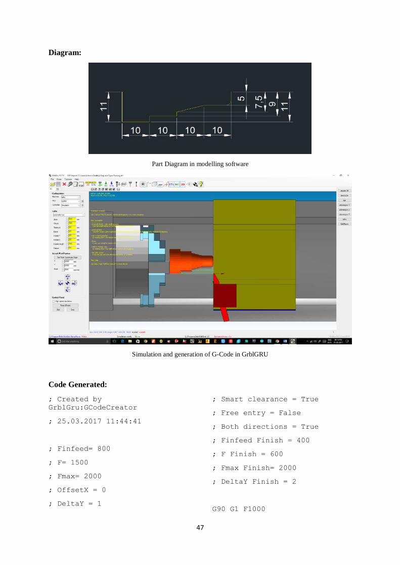
Diagram:
Part Diagram in modelling software
Simulation and generation of G-Code in GrblGRU
Code Generated:
; Created by
GrblGru:GCodeCreator
; 25.03.2017 11:44:41
; Finfeed= 800
; F= 1500
; Fmax= 2000
; OffsetX = 0
; DeltaY = 1
; Smart clearance = True
; Free entry = False
; Both directions = True
; Finfeed Finish = 400
; F Finish = 600
; Fmax Finish= 2000
; DeltaY Finish = 2
G90 G1 F1000
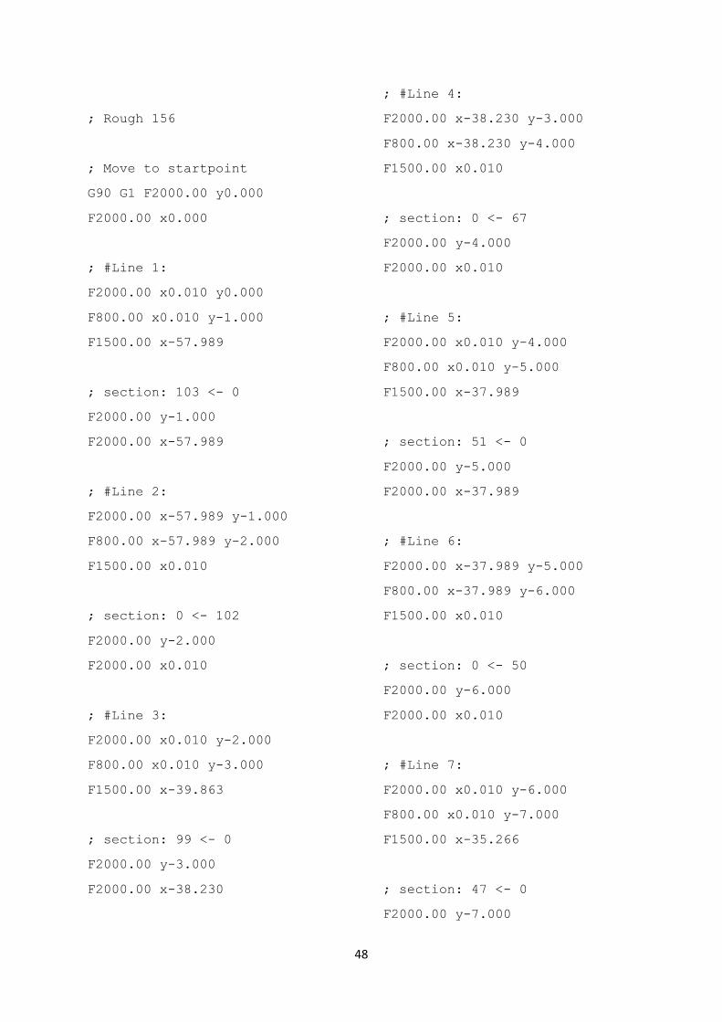
48
; Rough 156
; Move to startpoint
G90 G1 F2000.00 y0.000
F2000.00 x0.000
; #Line 1:
F2000.00 x0.010 y0.000
F800.00 x0.010 y-1.000
F1500.00 x-57.989
; section: 103 <- 0
F2000.00 y-1.000
F2000.00 x-57.989
; #Line 2:
F2000.00 x-57.989 y-1.000
F800.00 x-57.989 y-2.000
F1500.00 x0.010
; section: 0 <- 102
F2000.00 y-2.000
F2000.00 x0.010
; #Line 3:
F2000.00 x0.010 y-2.000
F800.00 x0.010 y-3.000
F1500.00 x-39.863
; section: 99 <- 0
F2000.00 y-3.000
F2000.00 x-38.230
; #Line 4:
F2000.00 x-38.230 y-3.000
F800.00 x-38.230 y-4.000
F1500.00 x0.010
; section: 0 <- 67
F2000.00 y-4.000
F2000.00 x0.010
; #Line 5:
F2000.00 x0.010 y-4.000
F800.00 x0.010 y-5.000
F1500.00 x-37.989
; section: 51 <- 0
F2000.00 y-5.000
F2000.00 x-37.989
; #Line 6:
F2000.00 x-37.989 y-5.000
F800.00 x-37.989 y-6.000
F1500.00 x0.010
; section: 0 <- 50
F2000.00 y-6.000
F2000.00 x0.010
; #Line 7:
F2000.00 x0.010 y-6.000
F800.00 x0.010 y-7.000
F1500.00 x-35.266
; section: 47 <- 0
F2000.00 y-7.000
49
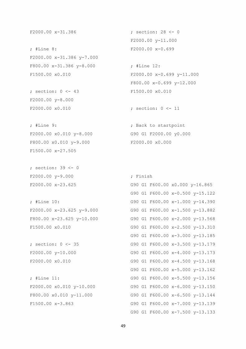
F2000.00 x-31.386
; #Line 8:
F2000.00 x-31.386 y-7.000
F800.00 x-31.386 y-8.000
F1500.00 x0.010
; section: 0 <- 43
F2000.00 y-8.000
F2000.00 x0.010
; #Line 9:
F2000.00 x0.010 y-8.000
F800.00 x0.010 y-9.000
F1500.00 x-27.505
; section: 39 <- 0
F2000.00 y-9.000
F2000.00 x-23.625
; #Line 10:
F2000.00 x-23.625 y-9.000
F800.00 x-23.625 y-10.000
F1500.00 x0.010
; section: 0 <- 35
F2000.00 y-10.000
F2000.00 x0.010
; #Line 11:
F2000.00 x0.010 y-10.000
F800.00 x0.010 y-11.000
F1500.00 x-3.863
; section: 28 <- 0
F2000.00 y-11.000
F2000.00 x-0.699
; #Line 12:
F2000.00 x-0.699 y-11.000
F800.00 x-0.699 y-12.000
F1500.00 x0.010
; section: 0 <- 11
; Back to startpoint
G90 G1 F2000.00 y0.000
F2000.00 x0.000
; Finish
G90 G1 F600.00 x0.000 y-16.865
G90 G1 F600.00 x-0.500 y-15.122
G90 G1 F600.00 x-1.000 y-14.390
G90 G1 F600.00 x-1.500 y-13.882
G90 G1 F600.00 x-2.000 y-13.568
G90 G1 F600.00 x-2.500 y-13.310
G90 G1 F600.00 x-3.000 y-13.185
G90 G1 F600.00 x-3.500 y-13.179
G90 G1 F600.00 x-4.000 y-13.173
G90 G1 F600.00 x-4.500 y-13.168
G90 G1 F600.00 x-5.000 y-13.162
G90 G1 F600.00 x-5.500 y-13.156
G90 G1 F600.00 x-6.000 y-13.150
G90 G1 F600.00 x-6.500 y-13.144
G90 G1 F600.00 x-7.000 y-13.139
G90 G1 F600.00 x-7.500 y-13.133

50
G90 G1 F600.00 x-8.000 y-13.127
G90 G1 F600.00 x-8.500 y-13.121
G90 G1 F600.00 x-9.000 y-13.115
G90 G1 F600.00 x-9.500 y-13.110
G90 G1 F600.00 x-10.000 y-
13.104
G90 G1 F600.00 x-10.500 y-
13.098
G90 G1 F600.00 x-11.000 y-
13.092
G90 G1 F600.00 x-11.500 y-
13.086
G90 G1 F600.00 x-12.000 y-
13.081
G90 G1 F600.00 x-12.500 y-
13.075
G90 G1 F600.00 x-13.000 y-
13.069
G90 G1 F600.00 x-13.500 y-
13.063
G90 G1 F600.00 x-14.000 y-
13.057
G90 G1 F600.00 x-14.500 y-
13.052
G90 G1 F600.00 x-15.000 y-
13.046
G90 G1 F600.00 x-15.500 y-
13.040
G90 G1 F600.00 x-16.000 y-
13.034
G90 G1 F600.00 x-16.500 y-
13.028
G90 G1 F600.00 x-17.000 y-
13.023
G90 G1 F600.00 x-17.500 y-
13.017
G90 G1 F600.00 x-18.000 y-
13.011
G90 G1 F600.00 x-18.500 y-
13.005
G90 G1 F600.00 x-19.000 y-
12.999
G90 G1 F600.00 x-19.500 y-
12.994
G90 G1 F600.00 x-20.000 y-
12.985
G90 G1 F600.00 x-20.500 y-
12.860
G90 G1 F600.00 x-21.000 y-
12.735
G90 G1 F600.00 x-21.500 y-
12.610
G90 G1 F600.00 x-22.000 y-
12.485
G90 G1 F600.00 x-22.500 y-
12.360
G90 G1 F600.00 x-23.000 y-
12.235
G90 G1 F600.00 x-23.500 y-
12.110
G90 G1 F600.00 x-24.000 y-
11.985
G90 G1 F600.00 x-24.500 y-
11.860
G90 G1 F600.00 x-25.000 y-
11.735
G90 G1 F600.00 x-25.500 y-
11.610
G90 G1 F600.00 x-26.000 y-
11.485
G90 G1 F600.00 x-26.500 y-
11.360
G90 G1 F600.00 x-27.000 y-
11.235
G90 G1 F600.00 x-27.500 y-
11.110
G90 G1 F600.00 x-28.000 y-
10.985
G90 G1 F600.00 x-28.500 y-
10.860
G90 G1 F600.00 x-29.000 y-
10.735

51
G90 G1 F600.00 x-29.500 y-
10.610
G90 G1 F600.00 x-30.000 y-
10.485
G90 G1 F600.00 x-30.500 y-
10.360
G90 G1 F600.00 x-31.000 y-
10.235
G90 G1 F600.00 x-31.500 y-
10.110
G90 G1 F600.00 x-32.000 y-9.985
G90 G1 F600.00 x-32.500 y-9.860
G90 G1 F600.00 x-33.000 y-9.735
G90 G1 F600.00 x-33.500 y-9.610
G90 G1 F600.00 x-34.000 y-9.485
G90 G1 F600.00 x-34.500 y-9.360
G90 G1 F600.00 x-35.000 y-9.235
G90 G1 F600.00 x-35.500 y-9.110
G90 G1 F600.00 x-36.000 y-8.985
G90 G1 F600.00 x-36.500 y-8.860
G90 G1 F600.00 x-37.000 y-8.735
G90 G1 F600.00 x-37.500 y-8.610
G90 G1 F600.00 x-38.000 y-8.485
G90 G1 F600.00 x-38.500 y-8.360
G90 G1 F600.00 x-39.000 y-8.235
G90 G1 F600.00 x-39.500 y-8.110
G90 G1 F600.00 x-40.000 y-4.988
G90 G1 F600.00 x-40.500 y-4.988
G90 G1 F600.00 x-41.000 y-4.988
G90 G1 F600.00 x-41.500 y-4.988
G90 G1 F600.00 x-42.000 y-4.988
G90 G1 F600.00 x-42.500 y-4.988
G90 G1 F600.00 x-43.000 y-4.988
G90 G1 F600.00 x-43.500 y-4.988
G90 G1 F600.00 x-44.000 y-4.988
G90 G1 F600.00 x-44.500 y-4.988
G90 G1 F600.00 x-45.000 y-4.988
G90 G1 F600.00 x-45.500 y-4.988
G90 G1 F600.00 x-46.000 y-4.988
G90 G1 F600.00 x-46.500 y-4.988
G90 G1 F600.00 x-47.000 y-4.988
G90 G1 F600.00 x-47.500 y-4.988
G90 G1 F600.00 x-48.000 y-4.988
G90 G1 F600.00 x-48.500 y-4.988
G90 G1 F600.00 x-49.000 y-4.988
G90 G1 F600.00 x-49.500 y-4.988
G90 G1 F600.00 x-50.000 y-4.988
G90 G1 F600.00 x-50.500 y-4.988
G90 G1 F600.00 x-51.000 y-4.988
G90 G1 F600.00 x-51.500 y-4.988
G90 G1 F600.00 x-52.000 y-4.988
G90 G1 F600.00 x-52.500 y-4.988
G90 G1 F600.00 x-53.000 y-4.988
G90 G1 F600.00 x-53.500 y-4.988
G90 G1 F600.00 x-54.000 y-4.988
G90 G1 F600.00 x-54.500 y-4.988
G90 G1 F600.00 x-55.000 y-4.988
G90 G1 F600.00 x-55.500 y-4.988
G90 G1 F600.00 x-56.000 y-4.988
G90 G1 F600.00 x-56.500 y-4.988
G90 G1 F600.00 x-57.000 y-4.988
G90 G1 F600.00 x-57.500 y-4.988
G90 G1 F600.00 x-58.000 y-4.988
G90 G1 F600.00 x-58.500 y-4.988
G90 G1 F600.00 x-59.000 y-4.988
G90 G1 F600.00 x-59.500 y-4.988
G90 G1 F600.00 x-60.000 y-0.988
G90 G1 F600.00 x-60.500 y-0.988
G90 G1 F600.00 x-61.000 y-0.988
G90 G1 F600.00 x-61.500 y-0.988

52
G90 G1 F600.00 x-62.000 y-0.988
G90 G1 F600.00 x-62.500 y-0.988
G90 G1 F600.00 x-63.000 y-0.988
G90 G1 F600.00 x-63.500 y-0.988
G90 G1 F600.00 x-64.000 y-0.988
G90 G1 F600.00 x-64.500 y-0.988
G90 G1 F600.00 x-65.000 y-0.988
G90 G1 F600.00 x-65.500 y-0.988
G90 G1 F600.00 x-66.000 y-0.988
G90 G1 F600.00 x-66.500 y-0.988
G90 G1 F600.00 x-67.000 y-0.988
G90 G1 F600.00 x-67.500 y-0.988
G90 G1 F600.00 x-68.000 y-0.988
G90 G1 F600.00 x-68.500 y-0.988
G90 G1 F600.00 x-69.000 y-0.988
G90 G1 F600.00 x-69.500 y-0.988
G90 G1 F600.00 x-70.000 y-0.988
G90 G1 F600.00 x-70.500 y-0.988
G90 G1 F600.00 x-71.000 y-0.988
G90 G1 F600.00 x-71.500 y-0.988
G90 G1 F600.00 x-72.000 y-0.988
G90 G1 F600.00 x-72.500 y-0.988
G90 G1 F600.00 x-73.000 y-0.988
G90 G1 F600.00 x-73.500 y-0.988
G90 G1 F600.00 x-74.000 y-0.988
G90 G1 F600.00 x-74.500 y-0.988
G90 G1 F600.00 x-75.000 y-0.988
G90 G1 F600.00 x-75.500 y-0.988
G90 G1 F600.00 x-76.000 y-0.988
G90 G1 F600.00 x-76.500 y-0.988
G90 G1 F600.00 x-77.000 y-0.988
G90 G1 F600.00 x-77.500 y-0.988
G90 G1 F600.00 x-78.000 y-0.988
G90 G1 F600.00 x-78.500 y-0.988
G90 G1 F600.00 x-79.000 y-0.988
G90 G1 F600.00 x-79.500 y-0.988
; Back to startpoint
G90 G1 F2000.00 y0.000
F2000.00 x0.000

53
6. CONCLUSION
A low cost DIY CNC Lathe machine has been designed and developed using conventional
off the shelf components of open source hardware and software, and sample sets of
experiments have been performed.
Current design uses wooden frame and will be replaced with mild steel for improved
strength, rigidity and durability. The next version will also aim at machining non-ferrous
metal workpiece with a higher degree of accuracy by incorporating sensors to it.
Addition of limit switches and associated sensors will provide feedback for optimum control
during machining operation and good accuracy.

APPENDIX I
Design Sheets
700
6x
3
0
60
67.
50
132
.50
140
200
50 30
AA
BB
CC
DD
66
55
44
33
22
11
DRAW
N
CHK
'D
APP
V'D
MFG
Q.A
UNLE
SS O
THER
WIS
E SP
ECIF
IED
:D
IMEN
SIO
NS
ARE
IN M
ILLIM
ETER
SSU
RFA
CE
FIN
ISH:
TOLE
RAN
CES
:
LINEA
R:
AN
GUL
AR:
FINIS
H:D
EBUR
R A
ND
BR
EAK
SHA
RP
EDG
ES
NA
ME
SIG
NA
TURE
DA
TE
MA
TERI
AL:
DO
NO
T SC
ALE
DRA
WIN
G
TITLE
:
DW
G N
O.
SCA
LE:1
:5SH
EET 1
OF
1
A4
Woo
den
bloc
kW
EIG
HT:
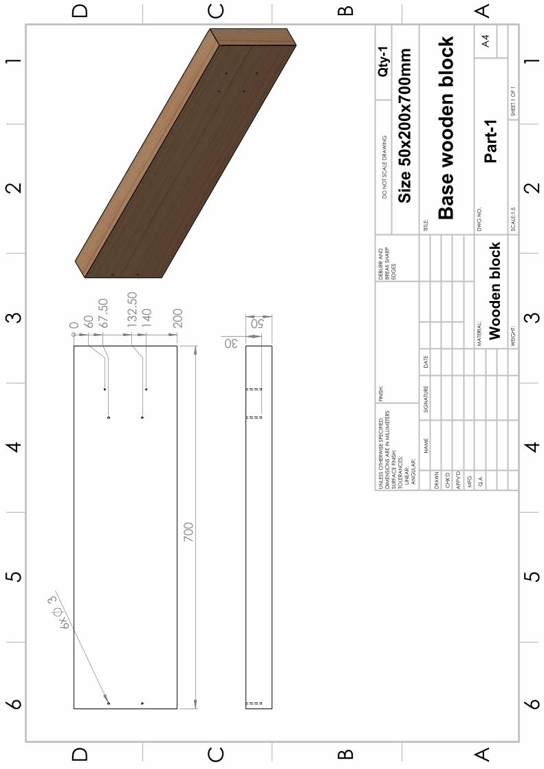
Base
woo
den
bloc
k
Size
50x
200x
700m
m
Part-
1
Qty
-1
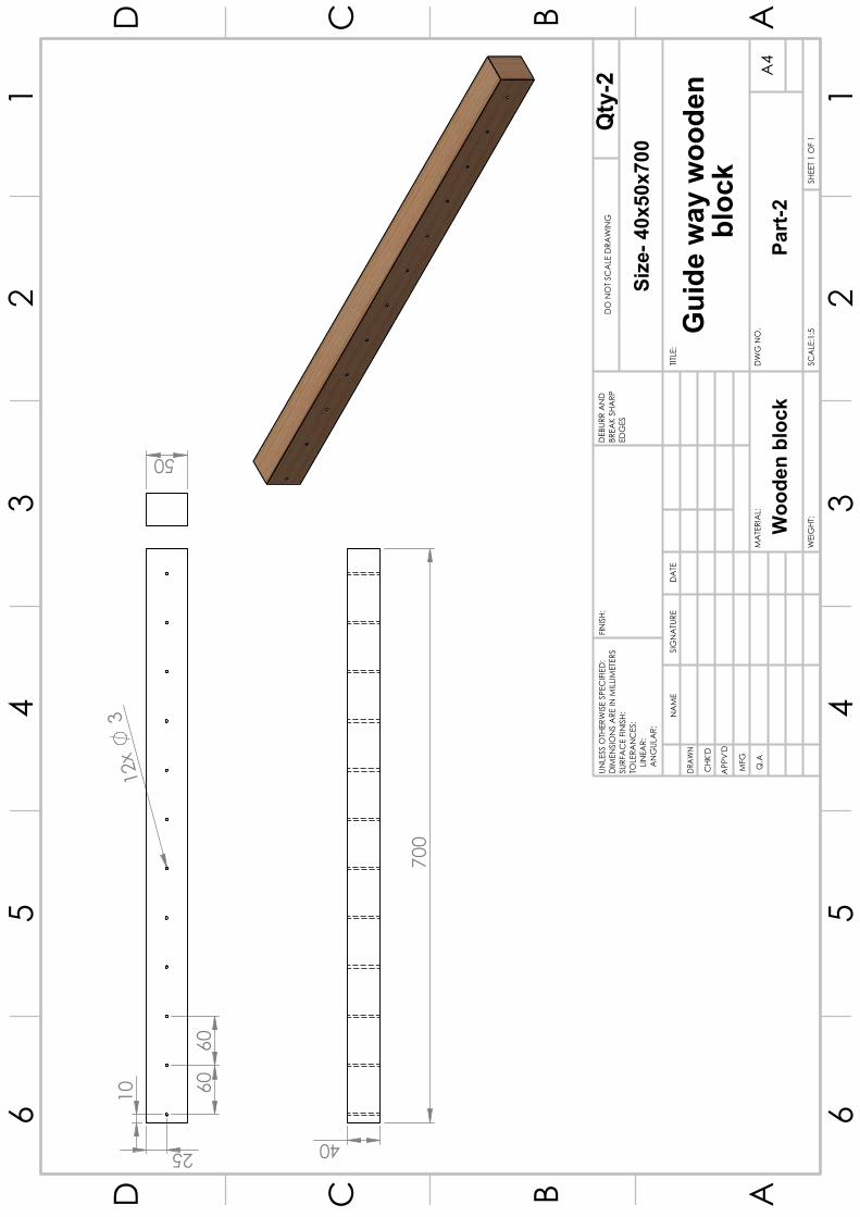
10 60
60
25
12x
3
50
700
40
AA
BB
CC
DD
66
55
44
33
22
11
DRAW
N
CHK
'D
APP
V'D
MFG
Q.A
UNLE
SS O
THER
WIS
E SP
ECIF
IED
:D
IMEN
SIO
NS
ARE
IN M
ILLIM
ETER
SSU
RFA
CE
FIN
ISH:
TOLE
RAN
CES
:
LINEA
R:
AN
GUL
AR:
FINIS
H:D
EBUR
R A
ND
BR
EAK
SHA
RP
EDG
ES
NA
ME
SIG
NA
TURE
DA
TE
MA
TERI
AL:
DO
NO
T SC
ALE
DRA
WIN
G
TITLE
:
DW
G N
O.
SCA
LE:1
:5SH
EET 1
OF
1
A4
WEI
GHT
:
Gui
de w
ay w
oode
n b
lock
Woo
den
bloc
kPa
rt-2
Size
- 40x
50x7
00Q
ty-2

680
12.50
15
AA
BB
CC
DD
66
55
44
33
22
11
DRAW
N
CHK
'D
APP
V'D
MFG
Q.A
FINIS
H:D
EBUR
R A
ND
BR
EAK
SHA
RP
EDG
ES
NA
ME
SIG
NA
TURE
DA
TE
MO
del
DO
NO
T SC
ALE
DRA
WIN
G
TITLE
:
DW
G N
O.
SCA
LE:1
:5SH
EET 1
OF
1
A4
HIW
IN G
EH 1
5SA
WEI
GHT
:
Qty
-2UN
LESS
OTH
ERW
ISE
SPEC
IFIE
D:
DIM
ENSI
ON
S A
RE IN
MILL
IMET
ERS
SURF
AC
E FI
NIS
H:TO
LERA
NC
ES:
LIN
EAR:
A
NG
ULA
R:Si
ze-1
2x15
x680
mm
Gui
dew
ay 1
34
19.50
55
AA
BB
CC
DD
66
55
44
33
22
11
DRAW
N
CHK
'D
APP
V'D
MFG
Q.A
UNLE
SS O
THER
WIS
E SP
ECIF
IED
:D
IMEN
SIO
NS
ARE
IN M
ILLIM
ETER
SSU
RFA
CE
FIN
ISH:
TOLE
RAN
CES
:
LINEA
R:
AN
GUL
AR:
FINIS
H:D
EBUR
R A
ND
BR
EAK
SHA
RP
EDG
ES
NA
ME
SIG
NA
TURE
DA
TE
MO
DEL
DO
NO
T SC
ALE
DRA
WIN
G
TITLE
:
DW
G N
O.
SCA
LE:1
:1SH
EET 1
OF
1
A4
HIW
IN G
EH 1
5SA
WEI
GHT
:
Size
-19.
50x3
4x55
mm
Gui
de w
ay s
lider
Part-
4
Qty
-4

45
R17
.25
6x
8
6x
4
12
10
30
24
8 2.30
12
AA
BB
CC
DD
66
55
44
33
22
11
DRAW
N
CHK
'D
APP
V'D
MFG
Q.A
UNLE
SS O
THER
WIS
E SP
ECIF
IED
:D
IMEN
SIO
NS
ARE
IN M
ILLIM
ETER
SSU
RFA
CE
FIN
ISH:
TOLE
RAN
CES
:
LINEA
R:
AN
GUL
AR:
FINIS
H:D
EBUR
R A
ND
BR
EAK
SHA
RP
EDG
ES
NA
ME
SIG
NA
TURE
DA
TE
MO
DEL
DO
NO
T SC
ALE
DRA
WIN
G
TITLE
:
DW
G N
O.
SCA
LE:1
:1SH
EET 1
OF
1
A4
SFU
1204
-3W
EIG
HT:
Part-
5
Leng
th- 4
0mm
Ball
Scre
w F
lang
e Nu
t
Qty
-2

580
R6
AA
BB
CC
DD
66
55
44
33
22
11
DRAW
N
CHK
'D
APP
V'D
MFG
Q.A
UNLE
SS O
THER
WIS
E SP
ECIF
IED
:D
IMEN
SIO
NS
ARE
IN M
ILLIM
ETER
SSU
RFA
CE
FIN
ISH:
TOLE
RAN
CES
:
LINEA
R:
AN
GUL
AR:
FINIS
H:D
EBUR
R A
ND
BR
EAK
SHA
RP
EDG
ES
NA
ME
SIG
NA
TURE
DA
TE
MO
DEL
DO
NO
T SC
ALE
DRA
WIN
G
TITLE
:
DW
G N
O.
SCA
LE:1
:10
SHEE
T 1 O
F 1
A4
WEI
GHT
:
Part-
6SF
U 12
04-3
Leng
th-5
80m
mQty
-1
Ball
Scre
w 1
17x
3
0 10
50
101.48 113.19 131.49
161.81
221.81
251.48
281.49 302.50
0
42.
50
52.
50
61.
96
75
87.
84
97.
50
107
.50
150
25
310
AA
BB
CC
DD
66
55
44
33
22
11
DRAW
N
CHK
'D
APP
V'D
MFG
Q.A
UNLE
SS O
THER
WIS
E SP
ECIF
IED
:D
IMEN
SIO
NS
ARE
IN M
ILLIM
ETER
SSU
RFA
CE
FIN
ISH:
TOLE
RAN
CES
:
LINEA
R:
AN
GUL
AR:
FINIS
H:D
EBUR
R A
ND
BR
EAK
SHA
RP
EDG
ES
NA
ME
SIG
NA
TURE
DA
TE
MA
TERI
AL:
DO
NO
T SC
ALE
DRA
WIN
G
TITLE
:
DW
G N
O.
SCA
LE:1
:5SH
EET 1
OF
1
A4
WEI
GHT
:
Woo
den
Bloc
k
Carr
iage
Bas
e
Part-
8
Size
-25x
150x
310m
mQ
ty-1
180
12.50
15
AA
BB
CC
DD
66
55
44
33
22
11
DRAW
N
CHK
'D
APP
V'D
MFG
Q.A
UNLE
SS O
THER
WIS
E SP
ECIF
IED
:D
IMEN
SIO
NS
ARE
IN M
ILLIM
ETER
SSU
RFA
CE
FIN
ISH:
TOLE
RAN
CES
:
LINEA
R:
AN
GUL
AR:
FINIS
H:D
EBUR
R A
ND
BR
EAK
SHA
RP
EDG
ES
NA
ME
SIG
NA
TURE
DA
TE
MA
TERI
AL:
DO
NO
T SC
ALE
DRA
WIN
G
TITLE
:
DW
G N
O.
SCA
LE:1
:2SH
EET 1
OF
1
A4
WEI
GHT
:
Gui
de w
ay-2
Part-
9
Size
-12.
50x1
5x18
0mm
HIW
IN G
EH 1
5SA
Qty
-2

24
.30
28
.30
R20
80
10
32.50
52.50
28.30
24.30
20
2x
4.2
0
8.20 11.80
32.
50
32.
50
AA
BB
CC
DD
66
55
44
33
22
11
DRAW
N
CHK
'D
APP
V'D
MFG
Q.A
UNLE
SS O
THER
WIS
E SP
ECIF
IED
:D
IMEN
SIO
NS
ARE
IN M
ILLIM
ETER
SSU
RFA
CE
FIN
ISH:
TOLE
RAN
CES
:
LINEA
R:
AN
GUL
AR:
FINIS
H:D
EBUR
R A
ND
BR
EAK
SHA
RP
EDG
ES
NA
ME
SIG
NA
TURE
DA
TE
MA
TERI
AL:
DO
NO
T SC
ALE
DRA
WIN
G
TITLE
:
DW
G N
O.
SCA
LE:1
:1SH
EET 1
OF
1
A4
WEI
GHT
:
Bear
ing
Bloc
k-1
Part-
103D
-Prin
ting
Size
-20x
55x8
0mm
Qty
-2

3x
3
0
20.40
80.40
140.40
250
40
30
40
250
AA
BB
CC
DD
66
55
44
33
22
11
DRAW
N
CHK
'D
APP
V'D
MFG
Q.A
UNLE
SS O
THER
WIS
E SP
ECIF
IED
:D
IMEN
SIO
NS
ARE
IN M
ILLIM
ETER
SSU
RFA
CE
FIN
ISH:
TOLE
RAN
CES
:
LINEA
R:
AN
GUL
AR:
FINIS
H:D
EBUR
R A
ND
BR
EAK
SHA
RP
EDG
ES
NA
ME
SIG
NA
TURE
DA
TE
MA
TERI
AL:
DO
NO
T SC
ALE
DRA
WIN
G
TITLE
:
DW
G N
O.
SCA
LE:1
:2SH
EET 1
OF
1
A4
WEI
GHT
:
Part-
11
Gui
dew
ay w
oode
n B
lock
-2
Size
-30x
40x2
50m
mQ
ty-2
Woo
den
bloc
k
220
R6
AA
BB
CC
DD
66
55
44
33
22
11
DRAW
N
CHK
'D
APP
V'D
MFG
Q.A
UNLE
SS O
THER
WIS
E SP
ECIF
IED
:D
IMEN
SIO
NS
ARE
IN M
ILLIM
ETER
SSU
RFA
CE
FIN
ISH:
TOLE
RAN
CES
:
LINEA
R:
AN
GUL
AR:
FINIS
H:D
EBUR
R A
ND
BR
EAK
SHA
RP
EDG
ES
NA
ME
SIG
NA
TURE
DA
TE
MO
DEL
:
DO
NO
T SC
ALE
DRA
WIN
G
TITLE
:
DW
G N
O.
SCA
LE:1
:5SH
EET 1
OF
1
A4
WEI
GHT
:
Ball
Scre
w-2
Part-
12
Size
- 12
mm
X 2
20m
mQ
ty-1
SFU
1204
-3
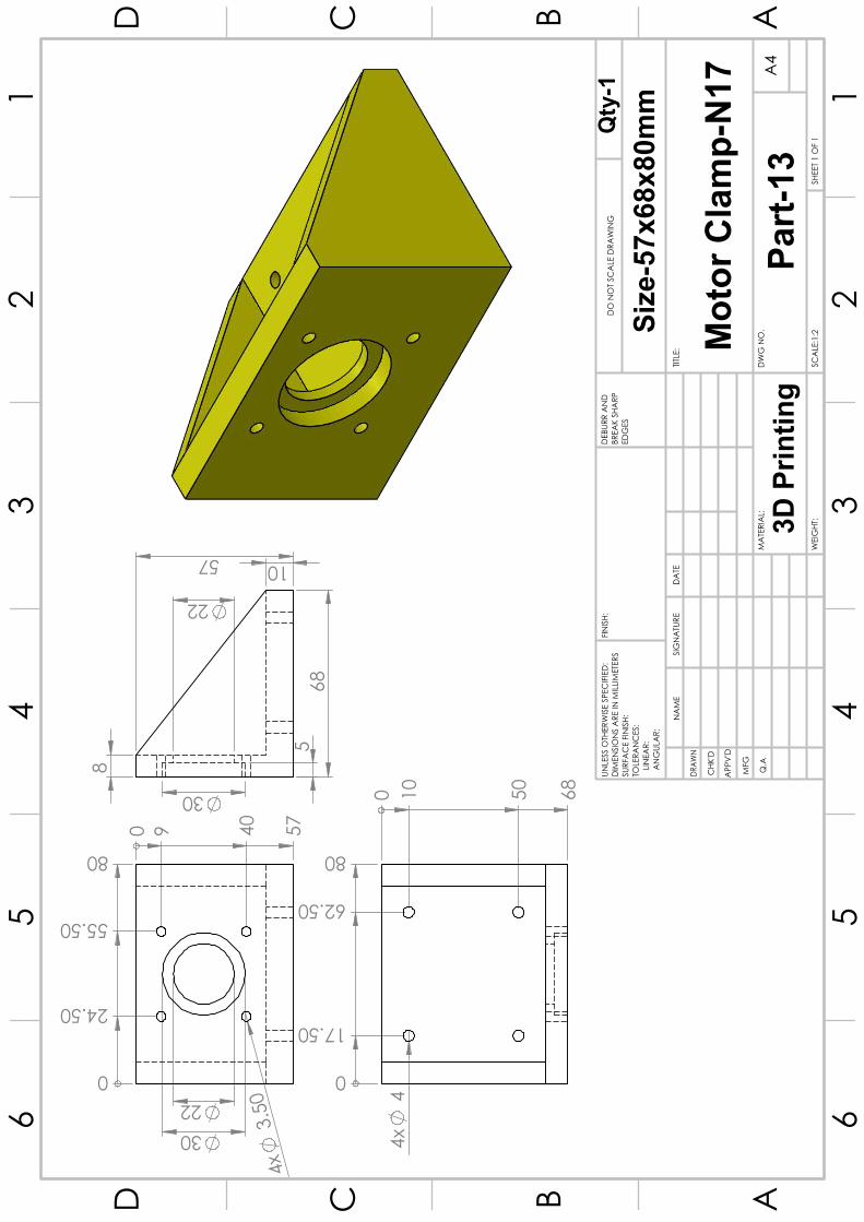
30 22
4x
3.5
0
0
24.50
55.50
80
0
9
40
57
57
68
8
10
5
22
30 4
x 4
0
17.50
62.50
80 0
1
0
50
68
AA
BB
CC
DD
66
55
44
33
22
11
DRAW
N
CHK
'D
APP
V'D
MFG
Q.A
UNLE
SS O
THER
WIS
E SP
ECIF
IED
:D
IMEN
SIO
NS
ARE
IN M
ILLIM
ETER
SSU
RFA
CE
FIN
ISH:
TOLE
RAN
CES
:
LINEA
R:
AN
GUL
AR:
FINIS
H:D
EBUR
R A
ND
BR
EAK
SHA
RP
EDG
ES
NA
ME
SIG
NA
TURE
DA
TE
MA
TERI
AL:
DO
NO
T SC
ALE
DRA
WIN
G
TITLE
:
DW
G N
O.
SCA
LE:1
:2SH
EET 1
OF
1
A4
WEI
GHT
:
Mot
or C
lam
p-N1
7Pa
rt-13
3D P
rintin
g
Size
-57x
68x8
0mm
Qty
-1

5
12
30
R12.05
AA
BB
CC
DD
66
55
44
33
22
11
DRAW
N
CHK
'D
APP
V'D
MFG
Q.A
UNLE
SS O
THER
WIS
E SP
ECIF
IED
:D
IMEN
SIO
NS
ARE
IN M
ILLIM
ETER
SSU
RFA
CE
FIN
ISH:
TOLE
RAN
CES
:
LINEA
R:
AN
GUL
AR:
FINIS
H:D
EBUR
R A
ND
BR
EAK
SHA
RP
EDG
ES
NA
ME
SIG
NA
TURE
DA
TE
MO
DEL
DO
NO
T SC
ALE
DRA
WIN
G
TITLE
:
DW
G N
O.
SCA
LE:2
:1SH
EET 1
OF
1
A4
WEI
GHT
:
Part-
14
Solid
Cou
pler
Size
-30
x20m
mQty
-2
coup
ler-
5mm
x12m
m

31
31
42
.30
5
64
AA
BB
CC
DD
66
55
44
33
22
11
DRAW
N
CHK
'D
APP
V'D
MFG
Q.A
UNLE
SS O
THER
WIS
E SP
ECIF
IED
:D
IMEN
SIO
NS
ARE
IN M
ILLIM
ETER
SSU
RFA
CE
FIN
ISH:
TOLE
RAN
CES
:
LINEA
R:
AN
GUL
AR:
FINIS
H:D
EBUR
R A
ND
BR
EAK
SHA
RP
EDG
ES
NA
ME
SIG
NA
TURE
DA
TE
MA
TERI
AL:
DO
NO
T SC
ALE
DRA
WIN
G
TITLE
:
DW
G N
O.
SCA
LE:1
:1SH
EET 1
OF
1
A4
WEI
GHT
:
Part-15
Nema-17
Qty-1
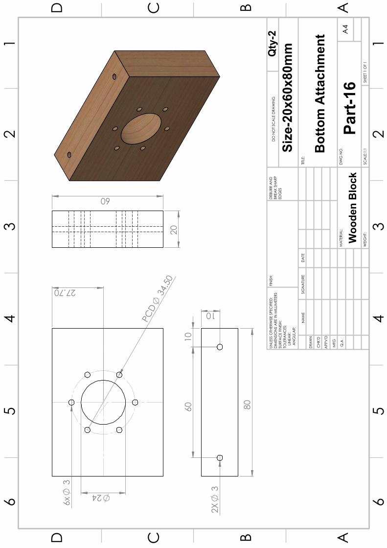
6x
3
24
27.70
PC
D 3
4.50
2
0
60
2X
3
80
10
60
10
AA
BB
CC
DD
66
55
44
33
22
11
DRAW
N
CHK
'D
APP
V'D
MFG
Q.A
UNLE
SS O
THER
WIS
E SP
ECIF
IED
:D
IMEN
SIO
NS
ARE
IN M
ILLIM
ETER
SSU
RFA
CE
FIN
ISH:
TOLE
RAN
CES
:
LINEA
R:
AN
GUL
AR:
FINIS
H:D
EBUR
R A
ND
BR
EAK
SHA
RP
EDG
ES
NA
ME
SIG
NA
TURE
DA
TE
MA
TERI
AL:
DO
NO
T SC
ALE
DRA
WIN
G
TITLE
:
DW
G N
O.
SCA
LE:1
:1SH
EET 1
OF
1
A4
WEI
GHT
:
Botto
m A
ttach
men
t
Qty
-2
Part-
16W
oode
n Bl
ock
Size
-20x
60x8
0mm
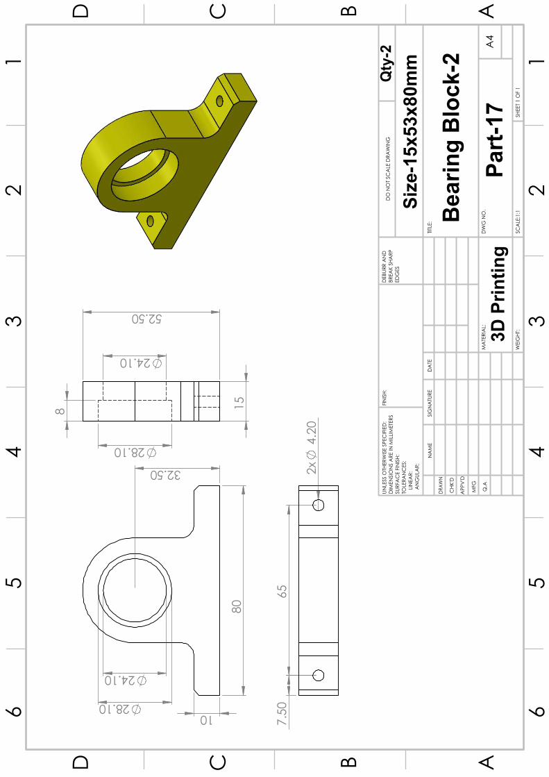
28.10
24.10
80
32.50
10
15
52.50
28.10
24.10
8
7.5
0 6
5
2x
4.2
0
AA
BB
CC
DD
66
55
44
33
22
11
DRAW
N
CHK
'D
APP
V'D
MFG
Q.A
UNLE
SS O
THER
WIS
E SP
ECIF
IED
:D
IMEN
SIO
NS
ARE
IN M
ILLIM
ETER
SSU
RFA
CE
FIN
ISH:
TOLE
RAN
CES
:
LINEA
R:
AN
GUL
AR:
FINIS
H:D
EBUR
R A
ND
BR
EAK
SHA
RP
EDG
ES
NA
ME
SIG
NA
TURE
DA
TE
MA
TERI
AL:
DO
NO
T SC
ALE
DRA
WIN
G
TITLE
:
DW
G N
O.
SCA
LE:1
:1SH
EET 1
OF
1
A4
WEI
GHT
:
Part-
17
Bear
ing
Bloc
k-2
Size
-15x
53x8
0mm
3D P
rintin
g
Qty
-2
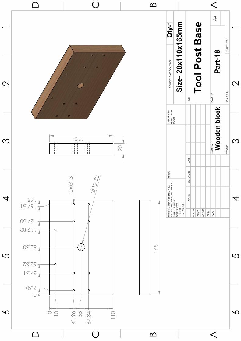
10x
3
12
.50
0 7.50
37.51 52.82
82.50
112.82 127.50
157.51 165
0
10
110
41.
96
67.
84
55
20
110
165
AA
BB
CC
DD
66
55
44
33
22
11
DRAW
N
CHK
'D
APP
V'D
MFG
Q.A
UNLE
SS O
THER
WIS
E SP
ECIF
IED
:D
IMEN
SIO
NS
ARE
IN M
ILLIM
ETER
SSU
RFA
CE
FIN
ISH:
TOLE
RAN
CES
:
LINEA
R:
AN
GUL
AR:
FINIS
H:D
EBUR
R A
ND
BR
EAK
SHA
RP
EDG
ES
NA
ME
SIG
NA
TURE
DA
TE
MA
TERI
AL:
DO
NO
T SC
ALE
DRA
WIN
G
TITLE
:
DW
G N
O.
SCA
LE:1
:2SH
EET 1
OF
1
A4
WEI
GHT
:
Tool
Pos
t Bas
e
Part-
18
Size
- 20x
110x
165m
mQ
ty-1
Woo
den
bloc
k

52.50
52.
50
12
.50
10
105 1
05
AA
BB
CC
DD
66
55
44
33
22
11
DRAW
N
CHK
'D
APP
V'D
MFG
Q.A
UNLE
SS O
THER
WIS
E SP
ECIF
IED
:D
IMEN
SIO
NS
ARE
IN M
ILLIM
ETER
SSU
RFA
CE
FIN
ISH:
TOLE
RAN
CES
:
LINEA
R:
AN
GUL
AR:
FINIS
H:D
EBUR
R A
ND
BR
EAK
SHA
RP
EDG
ES
NA
ME
SIG
NA
TURE
DA
TE
MA
TERI
AL:
DO
NO
T SC
ALE
DRA
WIN
G
TITLE
:
DW
G N
O.
SCA
LE:1
:1SH
EET 1
OF
1
A4
WEI
GHT
:
Part-
19To
p Po
st-1
Size
-10x
105x
105m
mQ
ty-1
Woo
den
bloc
k

12
.50
8x
M10
0
15
52.50
90
105
0
15
52.
50
90
105
20
105 1
05
AA
BB
CC
DD
66
55
44
33
22
11
DRAW
N
CHK
'D
APP
V'D
MFG
Q.A
UNLE
SS O
THER
WIS
E SP
ECIF
IED
:D
IMEN
SIO
NS
ARE
IN M
ILLIM
ETER
SSU
RFA
CE
FIN
ISH:
TOLE
RAN
CES
:
LINEA
R:
AN
GUL
AR:
FINIS
H:D
EBUR
R A
ND
BR
EAK
SHA
RP
EDG
ES
NA
ME
SIG
NA
TURE
DA
TE
MA
TERI
AL:
DO
NO
T SC
ALE
DRA
WIN
G
TITLE
:
DW
G N
O.
SCA
LE:1
:2SH
EET 1
OF
1
A4
WEI
GHT
:
Part-
20
Tool
Pos
t-2
Size
-20x
105x
105m
mQty
-1
Woo
den
Bloc
k
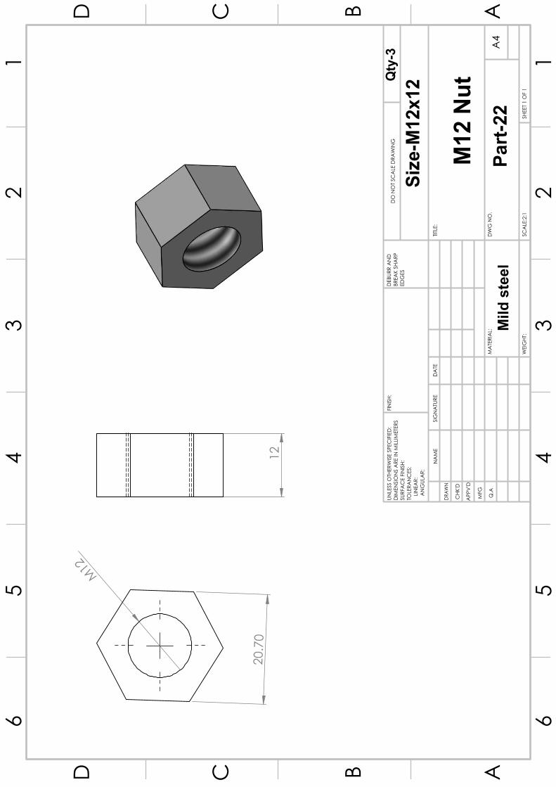
20.
70
M12
12
AA
BB
CC
DD
66
55
44
33
22
11
DRAW
N
CHK
'D
APP
V'D
MFG
Q.A
UNLE
SS O
THER
WIS
E SP
ECIF
IED
:D
IMEN
SIO
NS
ARE
IN M
ILLIM
ETER
SSU
RFA
CE
FIN
ISH:
TOLE
RAN
CES
:
LINEA
R:
AN
GUL
AR:
FINIS
H:D
EBUR
R A
ND
BR
EAK
SHA
RP
EDG
ES
NA
ME
SIG
NA
TURE
DA
TE
MA
TERI
AL:
DO
NO
T SC
ALE
DRA
WIN
G
TITLE
:
DW
G N
O.
SCA
LE:2
:1SH
EET 1
OF
1
A4
WEI
GHT
:
Part-
22
M12
Nut
Size
-M12
x12Q
ty-3
Mild
ste
el
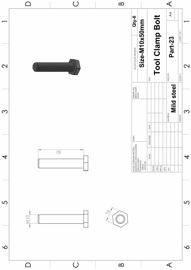
16
M10
50
AA
BB
CC
DD
66
55
44
33
22
11
DRAW
N
CHK
'D
APP
V'D
MFG
Q.A
UNLE
SS O
THER
WIS
E SP
ECIF
IED
:D
IMEN
SIO
NS
ARE
IN M
ILLIM
ETER
SSU
RFA
CE
FIN
ISH:
TOLE
RAN
CES
:
LINEA
R:
AN
GUL
AR:
FINIS
H:D
EBUR
R A
ND
BR
EAK
SHA
RP
EDG
ES
NA
ME
SIG
NA
TURE
DA
TE
MA
TERI
AL:
DO
NO
T SC
ALE
DRA
WIN
G
TITLE
:
DW
G N
O.
SCA
LE:1
:1SH
EET 1
OF
1
A4
WEI
GHT
:
Tool
Cla
mp
Bolt
Part-
23
Size
-M10
x50m
mQty
-6
Mild
ste
el
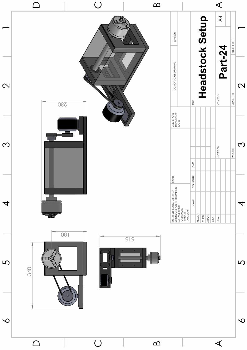
340
180
230
515
AA
BB
CC
DD
66
55
44
33
22
11
DRAW
N
CHK
'D
APP
V'D
MFG
Q.A
UNLE
SS O
THER
WIS
E SP
ECIF
IED
:D
IMEN
SIO
NS
ARE
IN M
ILLIM
ETER
SSU
RFA
CE
FIN
ISH:
TOLE
RAN
CES
:
LINEA
R:
AN
GUL
AR:
FINIS
H:D
EBUR
R A
ND
BR
EAK
SHA
RP
EDG
ES
NA
ME
SIG
NA
TURE
DA
TE
MA
TERI
AL:
DO
NO
T SC
ALE
DRA
WIN
GRE
VISI
ON
TITLE
:
DW
G N
O.
SCA
LE:1
:10
SHEE
T 1 O
F 1
A4
WEI
GHT
:
Head
stoc
k Se
tup
Part-
24

56
.30
47
47
5
78.
70
AA
BB
CC
DD
66
55
44
33
22
11
DRAW
N
CHK
'D
APP
V'D
MFG
Q.A
UNLE
SS O
THER
WIS
E SP
ECIF
IED
:D
IMEN
SIO
NS
ARE
IN M
ILLIM
ETER
SSU
RFA
CE
FIN
ISH:
TOLE
RAN
CES
:
LINEA
R:
AN
GUL
AR:
FINIS
H:D
EBUR
R A
ND
BR
EAK
SHA
RP
EDG
ES
NA
ME
SIG
NA
TURE
DA
TE
MA
TERI
AL:
DO
NO
T SC
ALE
DRA
WIN
G
TITLE
:
DW
G N
O.
SCA
LE:1
:2SH
EET 1
OF
1
A4
WEI
GHT
:
Step
per m
otor
-N23
Qty
-1
Part-
26

4x
4
38
0
24
47.50
71
95
0
9
32.
50
56
62
18
7.5
0 8
0
2x
3
AA
BB
CC
DD
66
55
44
33
22
11
DRAW
N
CHK
'D
APP
V'D
MFG
Q.A
UNLE
SS O
THER
WIS
E SP
ECIF
IED
:D
IMEN
SIO
NS
ARE
IN M
ILLIM
ETER
SSU
RFA
CE
FIN
ISH:
TOLE
RAN
CES
:
LINEA
R:
AN
GUL
AR:
FINIS
H:D
EBUR
R A
ND
BR
EAK
SHA
RP
EDG
ES
NA
ME
SIG
NA
TURE
DA
TE
MA
TERI
AL:
DO
NO
T SC
ALE
DRA
WIN
G
TITLE
:
DW
G N
O.
SCA
LE:1
:1SH
EET 1
OF
1
A4
WEI
GHT
:
Part-
27
N23
Mot
or C
lam
p
Size
-18x
62x9
5mm
Qty
-1
Woo
den
bloc
k

APPENDIX II
Product Datasheets


RE 83 301/2002-09 30
Rexroth – Precision Ball Screw AssembliesSingle Nut with Flange FEM-E-C
Mounting dimensions toDIN 69 051, Part 5
Flange type CWith standard seals
Reinforced seals, see Page 106
With backlash, reduced backlash,preload 2% or 5% C
For precision-rolled screws SN-R oftolerance grade T5, T7, T9 and ground-thread screws SN-F of tolerance grade P1,P3, P5, (T7)
d0 = nominal diameter
P = lead
(R = right-hand, L = left-hand)
DW = ball diameter
i = number of ball track turns
Size Part number Load ratings Speed*dyn. stat.
d0 x P x Dw - i C C0 vmax
(N) (N) [m/min]
16 x 5R x 3 - 4 1502-0-1065 12300 16100 3016 x 10R x 3 - 3 1502-0-4085 9600 12300 6016 x 16R x 3 - 3 1502-0-6065 9300 12000 9620 x 5R x 3 - 4 1502-1-1085 14300 21500 3020 x 20R x 3.5 - 3 1502-1-7065 13300 18800 12025 x 5R x 3 - 4 1502-2-1085 15900 27200 3025 x 10R x 3 - 4 1502-2-4085 15700 27000 6025 x 25R x 3.5 - 3 1502-2-8065 14700 23300 15032 x 5R x 3.5 - 4 1502-3-1085 21600 40000 2332 x 10R x 3.969 - 5 1502-3-4086 31700 58300 4732 x 20R x 3.969 - 3 1502-3-7065 19700 33700 9432 x 32R x 3.969 - 3 1502-3-9065 19500 34000 15040 x 5R x 3.5 - 5 1502-4-1086 29100 64100 1940 x 10R x 6 - 4 1502-4-4085 50000 86400 3840 x 12R x 6 - 4 1502-4-5065 49900 86200 4540 x 16R x 6 - 4 1502-4-6065 49700 85900 6040 x 20R x 6 - 3 1502-4-7085 37900 62800 7540 x 40R x 6 - 3 1502-4-9065 37000 62300 15050 x 5R x 3.5 - 5 1502-5-1086 32000 81300 1550 x 10R x 6 - 6 1502-5-4086 79700 166500 3050 x 12R x 6 - 6 1502-5-5066 79600 166400 3650 x 16R x 6 - 6 1502-5-6066 79400 166000 4850 x 20R x 6.5 - 5 1502-5-7086 75700 149700 6050 x 40R x 6.5 - 3 1502-5-9065 46500 85900 12063 x 10R x 6 - 6 1502-6-4086 88800 214300 2463 x 20R x 6.5 - 5 1502-6-7086 83900 190300 4863 x 40R x 6.5 - 3 1502-6-9065 53400 114100 9580 x 10R x 6.5 - 6 1502-7-4086 108400 291700 1980 x 20R x 12.7 - 6 1502-7-7096 262700 534200 30100 x 10R x 6.5 - 6 1502-8-4066 119500 371900 10100 x 20R x 12.7 - 6 1502-8-7066 295100 686400 20125 x 10R x 6.5 - 6 1502-9-4066 130600 468700 8125 x 20R x 12.7 - 6 1502-9-7066 326500 870400 16
FEM-E-C 20 x 5R x 3-4 1 2 T7 R 82Z120 41Z120 1250 1 0Order code:
Standard series
* See P. 95 Characteristic speed d0 . n and P. 116 Critical speed nk
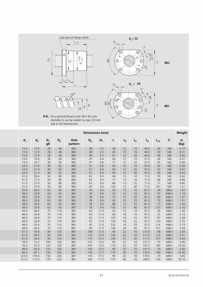
31 RE 83 301/2002-09
90°
L 4
L
L 3
22.5°
90°
30°
30°
D7
D7
SS
D6
D6
D 1D5
L 9L 9
Dw
d 0d 1
d 2
L 10
-0.0
5-0
.1D
1
d0 ≤ 32
d0 ≥ 40
N.B.: On a ground-thread screw SN-F the corediameter d2 can be smaller by max. 0.3 mmdue to the manufacture.
Lube port at flange center
BB2
BB1
Dimensions (mm) Weight
d1 d2 D1 D5 Hole D6 D7 L L3 L4 L9 L10 S mg6 pattern (kg)
15.0 12.9 28 48 BB2 38 5.5 38 12 10 44.0 26 M6 0.1915.0 12.9 28 48 BB2 38 5.5 45 12 16 44.0 33 M6 0.2115.0 12.9 28 48 BB2 38 5.5 61 12 20 44.0 49 M6 0.2619.0 16.9 36 58 BB2 47 6.6 40 12 10 51.0 28 M6 0.3119.3 16.7 36 58 BB2 47 6.6 77 12 25 51.0 65 M6 0.4924.0 21.9 40 62 BB2 51 6.6 45 12 10 55.0 33 M6 0.3624.0 21.9 40 62 BB2 51 6.6 64 12 20 55.0 52 M6 0.4724.0 21.4 40 62 BB2 51 6.6 95 12 30 55.0 83 M6 0.6331.0 28.4 50 80 BB2 65 9.0 48 13 10 71.0 35 M6 0.6231.0 27.9 50 80 BB2 65 9.0 77 13 16 71.0 64 M6 0.8431.0 27.9 50 80 BB2 65 9.0 84 13 25 71.0 71 M6 0.9031.0 27.9 50 80 BB2 65 9.0 120 13 40 71.0 107 M6 1.2139.0 36.4 63 93 BB1 78 9.0 54 15 10 81.5 39 M8x1 1.0338.0 33.8 63 93 BB1 78 9.0 70 15 16 81.5 55 M8x1 1.1938.0 33.8 63 93 BB1 78 9.0 75 15 25 81.5 60 M8x1 1.2738.0 33.8 63 93 BB1 78 9.0 90 15 25 81.5 75 M8x1 1.5138.0 33.8 63 93 BB1 78 9.0 88 15 25 81.5 73 M8x1 1.4438.0 33.8 63 93 BB1 78 9.0 142 15 45 81.5 127 M8x1 2.1649.0 46.4 75 110 BB1 93 11.0 54 15 10 97.5 39 M8x1 1.3948.0 43.8 75 110 BB1 93 11.0 90 18 16 97.5 72 M8x1 2.1448.0 43.8 75 110 BB1 93 11.0 105 18 25 97.5 87 M8x1 2.3848.0 43.8 75 110 BB1 93 11.0 128 18 25 97.5 110 M8x1 2.7548.0 43.4 75 110 BB1 93 11.0 132 18 25 97.5 114 M8x1 2.7348.0 43.4 75 110 BB1 93 11.0 149 18 45 97.5 131 M8x1 3.0461.0 56.8 90 125 BB1 108 11.0 90 22 16 110.0 68 M8x1 2.5661.0 56.4 95 135 BB1 115 13.5 132 22 25 117.5 110 M8x1 4.5161.0 56.4 95 135 BB1 115 13.5 149 22 45 117.5 127 M8x1 5.0478.0 73.3 105 145 BB1 125 13.5 95 22 16 127.5 73 M8x1 3.4076.0 67.0 125 165 BB1 145 13.5 170 25 25 147.5 145 M8x1 10.2098.0 93.4 125 165 BB1 145 13.5 95 25 16 147.5 70 M8x1 4.4096.0 87.1 150 202 BB1 176 17.5 170 30 25 178.5 140 M8x1 14.30
123.0 118.0 150 202 BB1 176 17.5 95 25 16 178.5 70 M8x1 5.65121.0 112.0 170 222 BB1 196 17.5 170 40 25 198.5 130 M8x1 16.10

Input voltage: 6-24V nominal, 30V absolute max.
Output current: Up to 12A continuous per channel. Peak loads may be up to 25A per
channel for a few seconds. These ratings are for input voltages up to 18v in still air without
additional heatsinking.
5V switching BEC: Up to 1A continuous and 1.5A peaks across the entire range of input
voltages.
Recommended power sources are:
• 5 to 18 cells NiMH or NiCd
• 2s to 6s lithium ion or lithium polymer. Sabertooth motor drivers have a lithium
battery mode to prevent cell damage due to over-discharge of lithium battery
packs.
• 6v to 24v lead acid
• 6v to 24v power supply (when in parallel with a suitable battery).
Dimensions:
Sabertooth 2x12 User’s Guide
Size: 2.5” x 2.95” x .6” 64 x 75 x 16mm
Weight: 2.2oz
• Switch settings: See the manufacturers instructions for operating mode, sample .
settings etc. (www.dimensionengineering.com/datasheets/Sabertooth2x12.pdf)

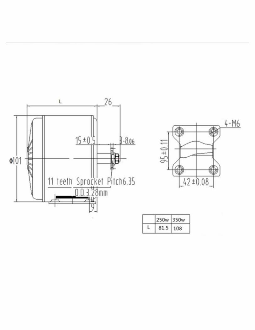
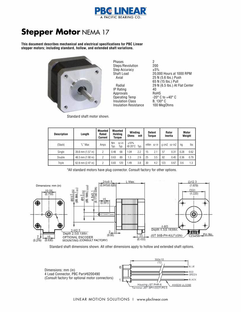
L INEAR MOTION SOLUTIONS I www.pbclinear.com
Dimensions: mm (in)
(CONSULT FACTORY)
Stepper Motor NEMA 17
Phases 2Steps/Revolution 200Step Accuracy ±5%Shaft Load 20,000 Hours at 1000 RPM Axial 25 N (5.6 lbs.) Push 65 N (15 lbs.) Pull Radial 29 N (6.5 lbs.) At Flat CenterIP Rating 40Approvals RoHSOperating Temp -20° C to +40° CInsulation Class B, 130° CInsulation Resistance 100 MegOhms
Dimensions: mm (in)4 Lead Connector, PBC Part#6200490(Consult factory for optional motor connectors)
Description LengthMounted
Rated Current
Mounted Holding Torque
Winding Ohms mH
Detent Torque
Rotor Inertia
Motor Weight
(Stack) “L” Max Amps Nm oz-inTyp. Typ.
±10%@ 20°C Typ. mNm oz-in g cm2 oz-in2 kg lbs
Single 39.8 mm (1.57 in) 2 0.48 68 1.04 2.2 15 2.1 57 0.31 0.28 0.62
Double 48.3 mm (1.90 in) 2 0.63 89 1.3 2.9 25 3.5 82 0.45 0.36 0.79
Triple 62.8 mm (2.47 in) 2 0.83 120 1.49 3.8 30 4.2 123 0.67 0.6 1.3
*All standard motors have plug connector. Consult factory for other options.
Standard shaft motor shown.
Standard shaft dimensions shown. All other dimensions apply to hollow and extended shaft options.
This document describes mechanical and electrical specifications for PBC Linear stepper motors; including standard, hollow, and extended shaft variations.

www.pbclinear.com I L INEAR MOTION SOLUTIONS
NEMA 17 Stepper Motor
0 300 600 900 1200 1500 1800
0
14
28
42
57
71
85
99
0.00
0.10
0.20
0.30
0.40
0.50
0.60
0.70
0 1,000 2,000 3,000 4,000 5,000 6,000Steps/SecRPM
Torq
ue (o
z-in
)
Torq
ue (N
m)
Speed
48 Vdc, 2 A rms 36 Vdc, 2 A rms 24 Vdc, 2 A rms 12 Vdc, 2 A rms
Bipolar Drive
Triple Stack
0 300 600 900 1200 1500 1800
071421283542505764
0.000.050.100.150.200.250.300.350.400.45
0 1,000 2,000 3,000 4,000 5,000 6,000Steps/SecRPM
Torq
ue (o
z-in
)
Torq
ue (N
m)
Speed
36 Vdc, 2 A rms
24 Vdc, 2 A rms
12 Vdc, 2 A rms
Bipolar Drive
Single Stack
0 300 600 900 1200 1500 1800
0
14
28
42
57
71
85
0.00
0.10
0.20
0.30
0.40
0.50
0.60
0 1,000 2,000 3,000 4,000 5,000 6,000Steps/SecRPM
Torq
ue (o
z-in
)
Torq
ue (N
m)
Speed
48 Vdc, 1.7 A rms 36 Vdc, 2 A rms 24 Vdc, 2 A rms 12 Vdc, 2 A rms
Bipolar Drive
Double Stack
*Performance curves apply to continuous duty cycles. Consult factory for intermittent cycles or other voltages.
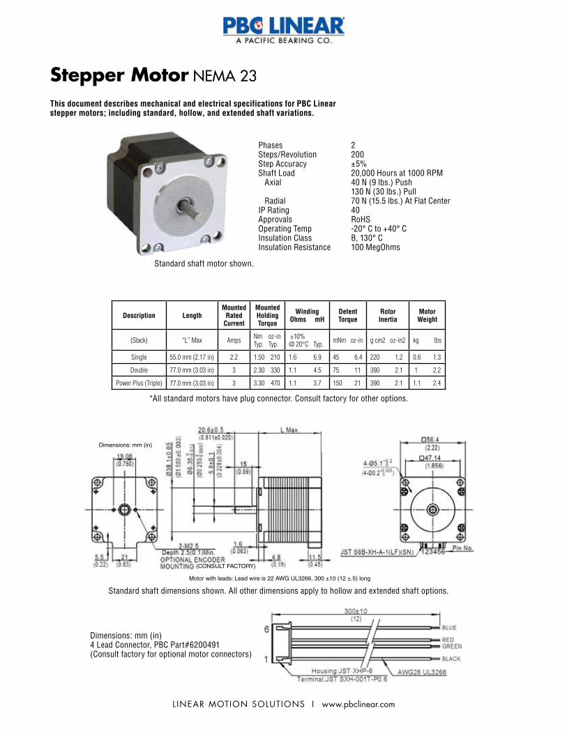
L INEAR MOTION SOLUTIONS I www.pbclinear.com
Stepper Motor NEMA 23
Description LengthMounted
Rated Current
Mounted Holding Torque
Winding Ohms mH
Detent Torque
Rotor Inertia
Motor Weight
(Stack) “L” Max Amps Nm oz-inTyp. Typ.
±10%@ 20°C Typ. mNm oz-in g cm2 oz-in2 kg lbs
Single 55.0 mm (2.17 in) 2.2 1.50 210 1.6 6.9 45 6.4 220 1.2 0.6 1.3
Double 77.0 mm (3.03 in) 3 2.30 330 1.1 4.5 75 11 390 2.1 1 2.2
Power Plus (Triple) 77.0 mm (3.03 in) 3 3.30 470 1.1 3.7 150 21 390 2.1 1.1 2.4
*All standard motors have plug connector. Consult factory for other options.
Dimensions: mm (in)4 Lead Connector, PBC Part#6200491(Consult factory for optional motor connectors)
Phases 2Steps/Revolution 200Step Accuracy ±5%Shaft Load 20,000 Hours at 1000 RPM Axial 40 N (9 lbs.) Push 130 N (30 lbs.) Pull Radial 70 N (15.5 lbs.) At Flat CenterIP Rating 40Approvals RoHSOperating Temp -20° C to +40° CInsulation Class B, 130° CInsulation Resistance 100 MegOhms
Standard shaft motor shown.
Dimensions: mm (in)
Motor with leads: Lead wire is 22 AWG UL3266, 300 ±10 (12 ±.5) long
(CONSULT FACTORY)
Standard shaft dimensions shown. All other dimensions apply to hollow and extended shaft options.
This document describes mechanical and electrical specifications for PBC Linear stepper motors; including standard, hollow, and extended shaft variations.

www.pbclinear.com I L INEAR MOTION SOLUTIONS
NEMA 23 Stepper Motor
0 300 600 900 1200 1500 1800
0
28
57
85
113
142
170
0.00
0.20
0.40
0.60
0.80
1.00
1.20
1.40
0 1,000 2,000 3,000 4,000 5,000 6,000Steps/SecRPM
Torq
ue (o
z-in
)
Torq
ue (N
m)
Speed
72 Vdc, 2 A rms 48 Vdc, 2 A rms 36 Vdc, 2 A rms 24 Vdc, 2 A rms
Bipolar Drive
Single Stack
0 300 600 900 1200 1500 1800
0285785113142170198227255283
0.000.200.400.600.801.001.201.401.601.802.00
0 1,000 2,000 3,000 5,000 6,000Steps/SecRPM
Torq
ue (o
z-in
)
Torq
ue (N
m)
Speed
24 Vdc, 3 A rms 12 Vdc, 3 A rms Bipolar Drive
Double Stack
Power Plus (Triple Stack)
*Performance curves apply to continuous duty cycles. Consult factory for intermittent cycles or other voltages.

APPENDIX III
Bill of Materials and Part Suppliers
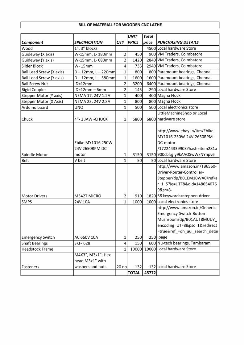
Component SPECIFICATION QTY
UNIT
PRICE
Total
price PURCHASING DETAILS
Wood 1”, 3” blocks 4500 Local hardware Store
Guideway (X axis) W-15mm, L- 180mm 2 450 900 VM Traders, Coimbatore
Guideway (Y axis) W-15mm, L- 680mm 2 1420 2840 VM Traders, Coimbatore
Slider Block W- 15mm 4 735 2940 VM Traders, Coimbatore
Ball Lead Screw (X axis) D – 12mm, L – 220mm 1 800 800 Paramount bearings, Chennai
Ball Lead Screw (Y axis) D – 12mm, L – 580mm 1 1600 1600 Paramount bearings, Chennai
Ball Screw Nut ID=12mm 2 3200 6400 Paramount bearings, Chennai
Rigid Coupler ID=12mm – 6mm 2 145 290 Local hardware Store
Stepper Motor (Y axis) NEMA 17, 24V 1.2A 1 400 400 Magna Flock
Stepper Motor (X Axis) NEMA 23, 24V 2.8A 1 800 800 Magna Flock
Arduino board UNO 1 500 500 Local electronics store
Chuck 4''- 3 JAW -CHUCK 1 6800 6800
LittleMachineShop or Local
hardware store
Spindle Motor
Ebike MY1016 250W
24V 2650RPM DC
motor 1 3150 3150
http://www.ebay.in/itm/Ebike-
MY1016-250W-24V-2650RPM-
DC-motor-
/172244339903?hash=item281a
900cbf:g:y9kAAOSwWxNYnpv6
Belt V belt 1 50 50 Local hardware Store
Motor Drivers M542T MICRO 2 910 1820
http://www.amazon.in/TB6560-
Driver-Router-Controller-
Stepper/dp/B01EM10WA0/ref=s
r_1_5?ie=UTF8&qid=148654076
9&sr=8-
5&keywords=stepper+driver
SMPS 24V,10A 1 1000 1000 Local electronics store
Emergency Switch AC 660V 10A 1 250 250
http://www.amazon.in/Generic-
Emergency-Switch-Button-
Mushroom/dp/B01AUT8MUU?_
encoding=UTF8&psc=1&redirect
=true&ref_=oh_aui_search_detai
lpage
Shaft Bearings SKF- 628 4 150 600 Nu-tech bearings, Tambaram
Headstock Frame 1 10000 10000 Local hardware Store
Fasteners
M4X3”, M3x1”, Hex
head M3x1” with
washers and nuts 20 no's each132 132 Local hardware Store
TOTAL 45772
BILL OF MATERIAL FOR WOODEN CNC LATHE