a-boom · instructivo! read, understand, and follow the following safety messages. serious injury...
TRANSCRIPT

© 2004 Alamo Group Inc.
ALAMO INDUSTRIAL1502 E. WalnutSeguin, Texas 78155830-379-1480
Assembly Instruction ManualNH TM120,130,140 & 155CASE-IH MXM 120,130,140 & 1552 & 4 Wheel Drive Cab Tractors
Manual P/N02981764
Tractors equipped with additional options, special equipment, tractor manufacturer modifications,new tractor models, or Customer alterations may prevent this Mount Kit from being properlymounted to the tractor. Alamo Industrial is not responsible for modifications to the MountKit toaccommodate these differences.
A-BOOM

TO THE OWNER/OPERATOR/DEALERAll implements with moving parts are potentially hazardous. There is no substitute for a cautious,safe-minded operator who recognizes the potential hazards and follows reasonable safetypractices. The manufacturer has designed this implement to be used with all its safety equipmentproperly attached to minimize the chance of accidents.BEFORE YOU START!! Read the safety messages on the implement and shown in your
manual. Observe the rules of safety and common sense!
WARRANTY INFORMATION:Read and understand the complete Warranty Statement found in this Manual. Fill out the WarrantyRegistration Form in full and return it within 30 Days. Make certain the Serial Number of the Machineis recorded on the Warranty Card and on the Warranty Form that you retain. The use of "will-fit"parts will void your warranty and can cause catastrophic failure with possible injury or death.

© 2004 Alamo Group Inc. 0 - 1
A-Boom (NH TM-120,130,140 & 155 Asy. Man.) 07/04
INTRODUCTIONABOUT THIS MANUAL:
The intent of this publication to provide the competent technician with the informationnecessary to perform the CORRECT Assembly to the Alamo Industrial Product. This will, in turnprovide for complete customer satisfaction
It is hoped that the information contained in this and other Manuals will provide enough detailto eliminate the need for contact of the Alamo Industrial Technical Service Dept. However, it shouldbe understood that many instances may arrive where correspondence with the Manufacturer isnecessary.CONTACTING MANUFACTURER: (Please help us Help You! Before You Call! )
Alamo Industrial Service Staff Members are dedicated to helping you solve your problem, oryour customer’s service problem as quickly and efficiently as possible. Unfortunately, we receiveentirely to many calls with only a minimum amount of information. In some cases, the correspondenthas never gone out to look at the equipment and merely calls inquiring of the problems described tohim by the operator or customer.
Most calls received by Alamo Industrial Service can be classified into approx. 6 general categories.1. Hydraulic or Mechanical Trouble Shooting.2. Request for Technical Information or Specifications.3. Mounting or Fitting Problem.4. Special Service Problem.5. Equipment Application Problems.6. Tractor Problem Inquiries.
HOW YOU CAN HELP:Make sure the call is necessary! Most of the calls received may not be necessary if the Dealer
Service Technician would do the following.
1. Check the Service Information at your Dealership provided by Alamo Industrial, Thiswould include, Service Bulletins, Information Bulletins, Parts Manuals, Operators Manuals, Assem-bly Manual or Service Manual, many of these are available via the Alamo Industrial Internet site(www.Alamo-Industrial.Com). Attempt to diagnose or repair problem before calling.
2. If a call to Alamo Industrial is needed, Certain Information should be available andready for the Alamo Industrial Service Staff. Such information as, Machine Model, Serial Number,Your Dealer Name, Your Account Number and Any other information that will be useful. Thisinformation is vital for the development of a prompt and correct solution to the problem. This will alsohelp to develop a database of problems and related solutions, which will expedite a solution to futureproblems of a similar nature.
3. The technician may be asked to provide detailed information about the problemincluding the results of any required trouble shooting techniques. If the information is not available,The technician may be asked to get the information and call back. Most recommendations for repairswill be based on the procedures listed in the Service Manual / Trouble Shooting Guide and Informationprovided by customer.
CONTACT ALAMO INDUSTRIAL:Alamo Industrial, 1502 E. Walnut St. Seguin TX. 78155, Technical Service Dept. PH: 830-379-1480

A-Boom (NH TM-120,130,140 & 155 Asy. Man.) 07/04© 2004 Alamo Group Inc. 0 - 2
Index Page No.Introduction..................................................................................... 0-1General Index................................................................................. 0-2 & 0-3User / Assembly Notes.....................................................................0-4
Section 1Safety Section................................................................................... 1-1 to 1-6
Section 2Pre-Delivery Check List......................................................................2-1 to 2-6
Section 3Wheel Weight Installation................................................................. 3-1 to 3-4
Section 4front Pump & Driveshaft Installation................................................. 4-1 to 4-6
Section 5Frame Rail / High Frame Setup / Assembly Installation.................. 5-1 to 5-22Frame Rail Set-up............................................................................ 5-2 to 5-6High Frame Setup..............................................................................5-7Front Frame Rail Supports............................................................... 5-8 to 5-9Frame Rail Pre-Assemble................................................................ 5-9 to 5-11Crossmember Frame Support Assembly........................................ 5-10High Frame Pre-Assemble............................................................... 5-11 to 5-15Tack Welding Frame Components.................................................. 5-16 to 5-17Mounting Valve Mounting Bracket to Frame Rail.............................. 5-17Remove Frame Components for Final Welding.............................. 5-18Install Boom Rest Stand................................................................... 5-19Install Frame Rail Axle Straps.......................................................... 5-19 To 5-20Install Boom Rest Support Plate...................................................... 5-19 to 5-22Install Hose Support Rings............................................................... 5-21
Section 6Hyd Tank & Counter Weight Installation............................................6-1 to 6-5Hydraulic Tank................................................................................... 6-2Counter Weight.................................................................................. 6-2Suction Hose......................................................................................6-2Counter Weight Cover....................................................................... 6-3Tank Return Filter.............................................................................. 6-3Tank Return Pressure Gauge........................................................... 6-3Tank Oil Level Sight Glass.................................................................6-3 to 6-4Tank Installed Decals.........................................................................6-4Cab Installed Decals.......................................................................... 6-5
INDEX - ASSEMBLY INSTRUCTION

A-Boom (NH TM-120,130,140 & 155 Asy. Man.) 07/04© 2004 Alamo Group Inc. 0 - 3
INDEX - ASSEMBLY INSTRUCTION
Index Page No.Section 7
Boom Installation.............................................................................. 7-1 to 7-6Boom Preparations........................................................................... 7-2Lifting Boom...................................................................................... 7-2 to 7-3Connecting Boom to High frame....................................................... 7-3 to 7-4Connect Swing Cylinder.................................................................... 7-4Pump to Tank & Pump to Cutter Valve Hose Installation..................7-5 to 7-6
Section 8Control Valve Controls Installation.....................................................8-1 to 8-24Standard Remote Control Cables.................................................... 8-2 to 8-11Optional Electric (Joystick) Controls................................................ 8-12 to 8-24
Section 9Head Installation............................................................................... 9-1 to 9-6Flail Axe Head....................................................................................9-2Flail Head........................................................................................... 9-3Ditcher Head...................................................................................... 9-4Timbercat Head................................................................................. 9-5X-Frame Square Rotary Head........................................................... 9-6
Section 10Fill Hydraulic Tank..............................................................................10-1 to 10-4
Section 11Hydraulic Start up Procedure.............................................................11-1 to 11-4
Section 12Boom Rest Plate and Boom Stop Installation................................... 12-1 to 12-6
Section 13Mount Kit Component Identification...................................................13-1 to 13-Mounting Restrictions........................................................................ 13-2 to 13-3Pump & Pump Drive Component Identification................................. 13-4 to 13-5Frame Rails and Frame Rail Hardware Identification........................13-6Frame Rail Crossmember Identification............................................ 13-7High Frame Mounting Tubes & Hardware......................................... 13-8Boom Rest Plate Installation..............................................................13-9High Frame, Tank and Counter Weight Mounting.............................13-10Pump Hose and Fitting Identification................................................. 13-11Joystick Seat Mount Components Identification.............................. 13-12

A-Boom (NH TM-120,130,140 & 155 Asy. Man.) 07/04
© 2004 Alamo Group Inc. 0 - 4
NOTES

© 2004 Alamo Group Inc. 1 - 1
A-Boom (NH TM-120,130,140 & 155 Asy. Man.) 07/04
SAFETYSECTION
Section 1
A-BOOM New Holland
TM-120,130,140 & 155Cab 2 & 4 Wheel Drive Tractor
Mounting Restrictions

A-Boom (NH TM-120,130,140 & 155 Asy. Man.) 07/04© 2004 Alamo Group Inc. 1 - 2
Read these assembly instructions through completely andunderstand them before proceeding with the assembly of theequipement.
A safe and careful operator is the best operator. Safety is of primary importanceto the manufacturer and should be to the owner/operator. Most accidents can beavoided by being aware of your equipment, your surroundings, and observingcertain precautions. The first section of this manual includes a list of SafetyMessages that, if followed, will help protect the operator and bystanders from injuryor death. Read and understand these Safety Messages before assembling,operating or servicing this Implement. This equipment should only be operated bythose persons who have read the Manual, who are responsible and trained, and whoknow how to do so safely and responsibly.
The Safety Alert Symbol combined with a Signal Word, as seen below, is usedthroughout this manual and on decals which are attached to the equipment. The SafetyAlert Symbol means: “ATTENTION! BECOME ALERT! YOUR SAFETY IS IN-VOLVED!” The Symbol and Signal Word are intended to warn the owner/operator ofimpending hazards and the degree of possible injury faced when operating this equip-ment..
CAUTION! The lowest level of Safety Message; warns of possible injury. Decals located on the Equipment with this Signal Word are Black and Yellow.
WARNING! Serious injury or possible death! Decals are Black and Orange.
DANGER! Imminent death/critical injury. Decals are Red and White. (SG-1)
Practice all usual and customary safe working precautions andabove all---remember safety is up to YOU. Only YOU can preventserious injury or death from unsafe practices.
Safety Section

A-Boom (NH TM-120,130,140 & 155 Asy. Man.) 07/04© 2004 Alamo Group Inc. 1 - 3
Si no lee Ingles, pida ayuda a alguien que si lo lea para que letraduzca las medidas de seguridad. (SG-3)
PELIGRO!
!LEA ELINSTRUCTIVO!
READ, UNDERSTAND, and FOLLOW the following SafetyMessages. Serious injury or death may occur unless care is takento follow the warnings and instructions stated in the Safety Mes-sages. Always use good common sense to avoid hazards.
(SG-2)
!Si no lee Ingles, pida ayuda a alguien quesi lo lea para que le traduzca las medidasde seguridad. (SG-3)
PELIGRO! LEA ELINSTRUCTIVO!
WARNING! Perform service, repairs and lubrication according to the maintenance section. Ensure theunit is properly lubricated as specified in the lubrication schedule and all bolts and nuts areproperly torqued. Failure to properly service, repair and maintain this Implement in goodoperating condition could cause component failure and possible serious injury or even death.(SG-35)
WARNING! Operate this Equipment only with a Tractor equipped with anapproved roll-over-protective system (ROPS). Always wear seatbelts. Serious injury or even death could result from falling off thetractor--particularly during a turnover when the operator could bepinned under the ROPS. (SG-7)
DANGER! Never work under the Implement, the framework, or any liftedcomponent unless the Implement is securely supported or blockedup to prevent sudden or inadvertent falling which could cause seriousinjury or even death. (SG-14)
WARNING! Use caution and wear protective gloves when handling sharp objects such as blades,knives, and other cutting edges. Be alert to worn component surfaces which have sharpedges. Sharp surfaces can inflict severe laceration injuries if proper hand protection is notworn. (SG-37)
Safety Section
A-Boom (NH TM-120,130,140 & 155 Asy. Man.) 07/04© 2004 Alamo Group Inc. 1 - 4
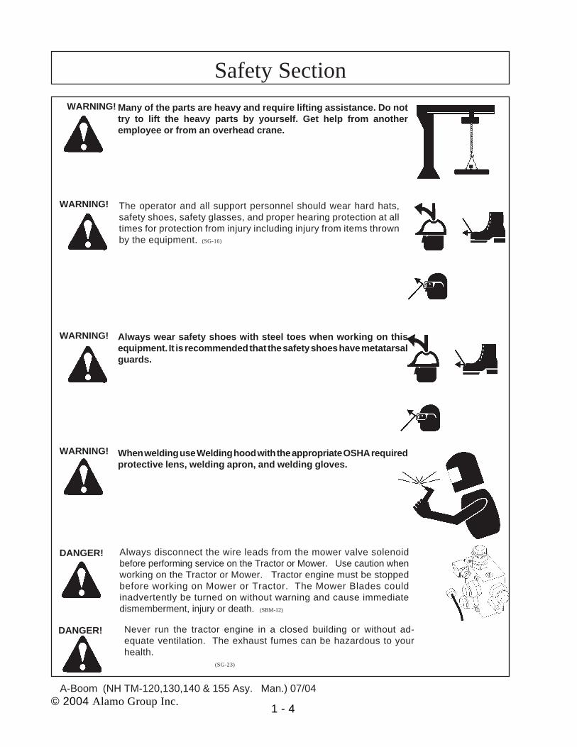
Many of the parts are heavy and require lifting assistance. Do nottry to lift the heavy parts by yourself. Get help from anotheremployee or from an overhead crane.
WARNING! The operator and all support personnel should wear hard hats,safety shoes, safety glasses, and proper hearing protection at alltimes for protection from injury including injury from items thrownby the equipment. (SG-16)
Always wear safety shoes with steel toes when working on thisequipment. It is recommended that the safety shoes have metatarsalguards.
When welding use Welding hood with the appropriate OSHA requiredprotective lens, welding apron, and welding gloves.
DANGER! Always disconnect the wire leads from the mower valve solenoidbefore performing service on the Tractor or Mower. Use caution whenworking on the Tractor or Mower. Tractor engine must be stoppedbefore working on Mower or Tractor. The Mower Blades couldinadvertently be turned on without warning and cause immediatedismemberment, injury or death. (SBM-12)
DANGER! Never run the tractor engine in a closed building or without ad-equate ventilation. The exhaust fumes can be hazardous to yourhealth. (SG-23)
WARNING!
WARNING!
WARNING!
Safety Section

A-Boom (NH TM-120,130,140 & 155 Asy. Man.) 07/04© 2004 Alamo Group Inc. 1 - 5
Before starting the mower make sure the area is clear and the floorhas been swept. The mower blade can throw objects several hundredfeet. Thrown objects could damge property or cause severe bodilyinjuries even death.
WARNING! Make certain that the “Slow Moving Vehicle” (SMV) sign is installed insuch a way as to be clearly visible and legible. When transporting theEquipment use the Tractor flashing warning lights and follow all localtraffic regulations. (SG-6)
DANGER! Start tractor only when properly seated in the Tractor seat. Starting atractor in gear can result in injury or death. Read the Tractor operatorsmanual for proper starting instructions. (SG-13)
DANGER! Do not operate this Equipment with hydraulic oil leaking. Oil isexpensive and its presence could present a hazard. Do not check forleaks with your hand! Use a piece of heavy paper or cardboard.High-pressure oil streams from breaks in the line could penetrate theskin and cause tissue damage including gangrene. If oil doespenetrate the skin, have the injury treated immediately by a physicianknowledgeable and skilled in this procedure. (SG-15)
WARNING! Always read carefully and comply fully with the manufacturers instruc-tions when handling oil, solvents, cleansers, and any other chemicalagent. (SG-22)
DANGER! All Safety Shields, Guards and Safety devices including(but not limited to) - the Deflectors, Chain Guards, SteelGuards, Gearbox Shields, PTO integral shields , andRetractable Door Shields should be used and main-tained in good working condition. All safety devicesshould be inspected carefully at least daily for missingor broken components. Missing, broken, or worn itemsmust be replaced at once to reduce the possibility ofinjury or death from thrown objects, entanglement, orblade contact. (SGM-3)
DANGER!
Safety Section

A-Boom (NH TM-120,130,140 & 155 Asy. Man.) 07/04
© 2004 Alamo Group Inc. 1 - 6
DANGER! NEVER use drugs or alcohol immediately before or while operating theTractor and Implement. Drugs and alcohol will affect an operator’salertness and coordination and therefore affect the operator’s ability tooperate the equipment safely. Before operating the Tractor orImplement, an operator on prescription or over-the-counter medica-tion must consult a medical professional regarding any side effects ofthe medication that would hinder their ability to operate the Equipmentsafely. NEVER knowingly allow anyone to operate this equipmentwhen their alertness or coordination is impaired. Serious injury ordeath to the operator or others could result if the operator is under theinfluence of drugs or alcohol. (SG-27)
DANGER! Operate the Tractor and/or Implement controls only while properlyseated in the Tractor seat with the seat belt securely fastened aroundyou. Inadvertent movement of the Tractor or Implement may causeserious injury or death. (SG-29)
WARNING! Engine Exhaust, some of its constituents, and certainvehicle components contain or emit chemicals known tothe state of California to cause cancer and birth defects
or other reproductive harm. (SG-30)
WARNING! Battery posts, terminals and related accessories containlead and lead compounds, chemicals known to the stateof California to cause cancer and birth defects or otherreproductive harm. Wash Hands after handling. (SG-31)
WARNING! Use extreme caution when getting onto the Implement to perform repairs, maintenanceand when removing accumulated material. Only stand on solid flat surfaces to ensuregood footing. Use a ladder or raised stand to access high spots which cannot be reachedfrom gound level. Slipping and falling can cause serious injury or death. (SG-33)
WARNING! Avoid contact with hot surfaces including hydraulic oil tanks, pumps, motors, valves andhose connections. Relieve hydraulic pressure before performing maintenance or repairs.Use gloves and eye protection when servicing hot components. Contact with a hot surfaceor fluid can cause serious injury from burns or scalding. (SG-34)
WARNING! Avoid contact with hot surfaces of the engine or muffler. Use gloves and eye protectionwhen servicing hot components. Contact with a hot surface or fluid can cause seriousinjury from burns or scalding. (SG-38)
Safety Section

© 2004 Alamo Group Inc. 2 - 1
A-Boom (NH TM-120,130,140 & 155 Asy. Man.) 07/04
A-BOOMNew Holland
TM-120,130,140 & 155Cab 2 & 4 Wheel Drive Tractor
TOOL REQUIREMENTSAND
PRE-DELIVERY INSPECTION CHECKLIST
Section 2

A-Boom (NH TM-120,130,140 & 155 Asy. Man.) 07/04© 2004 Alamo Group Inc. 2 - 2
Tools that are recommended to complete this assembly. There are number of different ways
to do things, some items are recommended to make assembly easier but may not be
required.
1. An over Head Hoist, the hoist (or Lift) should be a 2-1/2 ton capacity minimum. Hoist should
be able to move and stop within fractions of an inch. Hoist should also have a 12 foot lift
(Required).
2. Compressed Air, Air must be filtered and dry. A Safety air nozzle for blowing out Hoses and
Fitting prior to assembly. (Required).
3. Complete Air Impact Sockets, 1/2" Drive and 3/4” drive (Recommended).
4. Torque Wrench, 400-ft lb. rating, can use a Torque Amplifier Wrench. (Required)
5. Complete Set of Hand Wrenches from 7/16" to 2" (Recommended).
6. Assortment of Screwdrivers, (Short ones and Long ones). (Required)
7. Electric Grinder or Air Grinder, Size according to needs (Required).
8. Burr Grinder, Electric or Air optional, for resizing Holes and removing Burrs from stamped
metal or stamped holes. (Required)
9. Welder, capable of welding up to 3/8" material, Use experienced Welder Personnel.
(Required)
10. Flame Proof or flame retardant Material to Cover and protect Tractor finish and components
during assembly. (Required)
11. A good fire Extinguisher on hand before any welding or grinding begins. (Required)
12. Clean dust free work area, clean Lint Free towels or wipes. Do not do any welding, use
compressed Air or lay out any component unless area is clean. Material the size of a human
hair can contaminate the Hydraulic System (Required).
13. A place to keep all Components separate and clean until ready for them (Recommended)
14. Electrical Butt connectors and Electrical Pliers. (Required)
15. Paint Scraper to remove Paint before welding. (Recommended)
16. Floor Jack, 2-1/2 Ton capacity (Required)
17. An assortment of large C-Clamps (Required)
Assembly Tools & Supplies Needed

A-Boom (NH TM-120,130,140 & 155 Asy. Man.) 07/04© 2004 Alamo Group Inc. 2 - 3
Pre-Operation Inspection: After Assembly is complete. Check the following items beforeoperating the unit to assure that they are properly assembled. (See following page 1-4 for compo-nent location)
Safety Equipment:
----- Operators Manual is with Unit.----- The Safety Decals are installed as listed in the Assembly Manual.----- Valve operation plate is installed.----- Operators cage or Tractor Cab is in place. (Item 1 page 1-5)----- Deflectors are installed on the Mower Head. (Item 2 page 1-5)----- Tractor Rops or Cab with seatbelts installed properly.
Frame and Boom:
----- Axle Plate Bolts are torqued to 240 ft. lbs. (Item 3 page 1-5)----- Boom Rest Axle Plate Bolts are torqued to 240 ft. lbs.----- Front Rail Bolts are torqued to 170 ft. lbs. (Item 17 page 1-5)----- Front Support Bolts are torqued to 240 ft. lbs. (Item 4 page 1-5)----- Hydraulic Tank mounting Pins / Bolts in place correctly.----- Boom Main Pins are torqued to 170 ft. lbs.----- King Pin Retaining Nut is properly locked in place.----- All Welds inspected to insure proper welds and locations.
Hydraulic System:
----- Oil Level in Hydraulic Tank is within the sight gauge. (Item 5 page 1-5)----- Hose connections are tightened according to specifications.----- Hoses do not have any kinks or twist in them.----- Front Pump Shaft adapter bolts are tight. (Item 6 page 1-5)----- Front Pump Shaft Coupler / Drive Shaft is lubricated and has an anti-seize compound
on the Splines of Pump and Shafts. (Item 7 page 1-5)----- The Pump Drive Shaft has correct alignment.----- Suction Hose has no leaks or kinks.
Rotary Mower Head:
----- Skid Shoe Bolts are torqued to 120 ft. lbs. (Item 8 page 1-5)----- Spindle Housing Bolts are torqued to 400 ft. lbs. (Item 9 page 1-5)----- The Spindle Housing is properly lubricated. (item 10 page 1-5)----- Motor Bolts are torqued to 120 ft. lbs. (Item 11 page 1-5)----- Blade Carrier (Bar) Bolts torque to 400 ft. lbs. (Item 12 page 1-5)----- All Blade Bolts are torqued, the retaining Pins are in place. (item 13 page 1-5)----- Blades Swing freely. (Item 14 page 1-5)
Pre-Delivery Inspection Checklist

A-Boom (NH TM-120,130,140 & 155 Asy. Man.) 07/04© 2004 Alamo Group Inc. 2 - 4
Pre-Operation Inspection: Check the following items before operating the unit to assurethat they are properly assembled. (See following page 1-4 for component location)
Flail Mower Head:___ Skid Shoe Bolts are torqued to 120 ft-lbs (Item 15 page 5)___ Motor Bolts are torqued to 120 ft-lbs___ Belt Alignment& tension adjustment is correct___ Cutter shaft bearings are properly lubricated___ Roller bearings are properly lubricated (Item 16 Page 5)___ Blades swing freely
Tractor Mower Operation Inspection:___ Using all Safety precautions, operate the Tractor and Mower unit for 30 minutes and
while the unit is running check the following items: Note! Only make adjustments after the mower has been turned off and all motion has stopped and all hydraulic pressurehas been relieved.
___ No Hydraulic oil leaks at the hose connections___ Operate the boom and mower head throughout its full range of motion and check
for hose's rubbing, pinching, or kinking.___ Make sure the Return Filter Gauge is reading in the Green after Oil is warm.___ Check the function of the Mower Head On-Off Valve and switch for proper function___ Make sure that the tractor will not start with the mower on-off switch in the on
position.___ Check the Blade Rotation for the Rotary Mower Head to make sure it is turning
Clockwise looking from the top of the mower deck.___ Make sure the control valve boom movements agree with the valve operation decal.___ Make Sure Boom Movement operates as expected and is smooth and under control
(no air in the control system)___ Look for any unusual or excessive noise or vibrations.___ Make sure all Wheel Weights are installed, Tires are Filled with liquid and Counter
Weight is installed___ Make sure the left rear wheel of the tractor stays on the ground when the boom is
fully extended horizontally with 200 lbs. placed on the outside of the mower head.
Post-Operation Inspection:___ Check that the oil in the hydraulic tank has not turned milky in color or has foam on top.___ Check that there are no loose fasteners or hardware.
Pre-Delivery Inspection Checklist

A-Boom (NH TM-120,130,140 & 155 Asy. Man.) 07/04© 2004 Alamo Group Inc. 2 - 5
Tractor - Mower Component Location
1
2
3
4
6
7
8
9
10
11
12
1314
15
16
17
2

A-Boom (NH TM-120,130,140 & 155 Asy. Man.) 07/04
© 2004 Alamo Group Inc. 2 - 6
NOTES

© 2004 Alamo Group Inc. 3 - 1
A-Boom (NH TM-120,130,140 & 155 Asy. Man.) 07/04
A-BOOMNew Holland
TM-120,130,140 & 155Cab 2 & 4 Wheel Drive Tractor
Wheel Weight Installation
Section 3

A-Boom (NH TM-120,130,140 & 155 Asy. Man.) 07/04© 2004 Alamo Group Inc. 3 - 2
Rear Wheel Counter Weight
Item Part No. Qty Description
1 02979603 3 Hex Head Bolt, 7/8" NC X 16"2 02971569 3 Wheel Weight Washer, Special3 02970758 1 Wheel Weight Casting, 1400 lbs.4 5JRC1490 3 Locknut, Top Lock 7/8" NC5 02977486 a/r Wheel Weight Adapter Kit (Not shown)
Note: some Older Units used a All Thread Rod with Hex Nuts Lock Nuts, with Flat Washerand Lock washer. This was replaced with the Bolt Type shown above. These Bolt and Nutcombinations will replace the old All Thread type.
1
2
3 4Rotate Washer to Match Bolt
Circle dia. and Washer fits intoWheel Weight Slot.
Bolt is shown extra long indrawing for illustration
only
Fill Left Rear Wheel with Liquid:
The Left Rear Wheel must be filled with liquid. Alamo Industrial recommends a CalciumChloride Water Mixture. The recommended Ratio of a 30 / 70 mix (30% Calcium Chloride and 70%Water), this mixture will add weight at about 10.5 lbs per gallon. Follow the Mixture proceduresfurnished by the Manufactured of the Brand of Calcium Chloride that you are using. It is alsorecommended that a trained person installs the calcium Chloride. Calcium Chloride must be added inaddition to the Steel Wheel Weight and the Counter Weight that hangs on the Left Side. It is Notrecommended to use straight Water in the Wheel as this would not provide protection against freezing.A 30/70 Calcium Chloride Water mixture provides anti-freeze to approx -50 deg. F. below 0.
Wheel Weight1400 lbs.
Figure 1

A-Boom (NH TM-120,130,140 & 155 Asy. Man.) 07/04© 2004 Alamo Group Inc. 3 - 3
Rear Wheel Counter Weight
Installing Wheel Weight1. This Wheel Weight is 1400 lbs. Always usecaution when working with it.2. Set Wheel Width. Make certain that you haveset the wheel width to where you need it beforeinstalling wheel weight. (See Figure 2). This maymean turning wheels and/ or wheel disk around orswitching tire and wheels from side to side beforeturning them around. It is recommended to extendthe wheels out as far as possible for wheel trackwidth.3. Locate the three Holes in LH Rear Wheel.Make sure these holes are 15/16" dia. if not, theymust be reamed out. (See Figure 3)4. Lift Left Rear Tractor Wheel till it just clearsthe ground. This will allow the Wheel to be rotatedwhen aligning mounting holes for Weight. WheelWeight is shown with optional extra weight platesadded to the wheel weight. These optional plate willweigh approx 135 lbs each plate (3 plate equalapprox 405 lbs extra) (See Figure 4) The optionalextra weights will have to be special order item.5. Using a forklift, lift Wheel Weight into Wheel.When Wheel Weight is centered in Wheel SecureForklift and Set Parking Brake on Forklift. Insert oneof the three bolts through Weight and Wheel (RotateWheel to align holes if needed). Install a Hex LockNut on inside. Insert the other two Bolts throughWeight and Wheel and start the other two Locknuts.Do not tighten yet. (See Figure 3)6. Looking at the outside make sure the threespecial Washers (See Figure 1) are aligned with theSlots in the Wheel Weight. Tighten the three Boltsnow. You will need an assistant to hold the other Sidewhile you are tightening the Bolts. While tighteningBolts, check to make sure the three special washersare seated correctly. If these Bolts are tightened andwasher are not seated into the recess on WheelWeight, damage will occur. (See Figure 3)7. Remove forklift away from Wheel and Weight.Recheck tightness of Wheel Weight retaining Bolts.Bolts should torque to 500 ft. lbs.
Figure 3
Wheel Weight Mntg Locknuts
Figure 4
Figure 2
Optional Extrawheel Weights
installed

A-Boom (NH TM-120,130,140 & 155 Asy. Man.) 07/04© 2004 Alamo Group Inc. 3 - 4
NOTES

© 2004 Alamo Group Inc. 4 - 1
A-Boom (NH TM-120,130,140 & 155 Asy. Man.) 07/04
A-BoomNew Holland
TM-120,130,140 & 155Cab 2 & 4 Wheel Drive Tractor
Front Pump & Drive Shaft Installation
Section 4

A-Boom (NH TM-120,130,140 & 155 Asy. Man.) 07/04
© 2004 Alamo Group Inc. 4 - 2
Pump / Drive Assembly Instructions
Installing Pump, Pump Drive Components and Hydraulic Tank:This Section covers installation of Pump and Pump Drive Components, Pump Assembly and
the Hydraulic Tank. Some precautions must be followed during the Assembly Process and before unitis ever started for the first time.1. Tractor must be disabled to prevent accidental engine start and prevent damage to components.2. All Fittings, Hose, Cylinders, Tank must be kept plugged at all times, No part of the Hydraulic
System can be left open at any time during mounting process, this will keep system clean.3. All Tools, Work Area, Components and Workers Hands must remain Clean when working on
any part of the Hydraulic System.4. All components should be rechecked for tightness at least twice, Hose routing also double
checked.5. Shown in Figure 1 is the schematic for the pump mounting components, showing the driveshaft
going through the front bolster of tractor. Located these components in the packing crate. (SeeFigure 1) NOTICE See Parts list as to which driveshaft is used on which tractor model!
Pump & Driveshaft and components :Part No. Qty Description:02979649 1 Spacer, f/ Pulley Adapter02702900 1 Hub, Pulley Adapter02981047 1 Driveshaft (use on NH TM 4 WD Model)02979634 1 Driveshaft (use on NH TM 2 WD Model)02980625 1 Driveshaft (use on Case-IH MXM 2 or 4 WD Model)02957635 1 Splined Coupler 1" X 13 Spline02979673 1 Pump Mount Plate02961829 1 Tandem Pump Asy
Figure 1Pump & Driveline Schematic
Tractor Engine Pulley
Pulley Adpater w/ MountingBolts & Washers (4 bolts)
Pump Pressure Ports (large portto motor, small port to cyl controlvalve supply) These ports are ontheRH side.
Pump (Reference)
Pulley Adapter & SpacerPump Mount Plate (2 upper holesuse counter sunk head bolts
123451234512345
Splined Coupler
1" X 13 Spline Driveshaft
123123
1212
12
Suction Port on LH Side
1212
11
12345123451234512345121212

A-Boom (NH TM-120,130,140 & 155 Asy. Man.) 07/04© 2004 Alamo Group Inc. 4 - 3
Pump & Driveshaft components :
1. Preparing Pulley Adapter, The pulleyadapter has US standard size holes, the EngineCrankshaft pulley uses Metric Bolts which will notgo through the pulley adapter hub (P/N 02702900).The Pulley adapter will need to have the steelbushings in the pulley adapter reamed (Drilled)out to 31/64" hole, this will allow the metric bolts tofit the holes. Use a drill press and clamp theadapter securely when drilling them out. Keep thealignment straight and do not bore them oversize(See Figure 2).
2. Pulley Adapter Spacer, The pulley adapterspacer (P/N 02979649) is installed between thepulley adapter (P/N 02702900) and the crank-shaft pulley (See Figure 1 & 3).
3. Insert Pulley adapter into Tractor EngineCompartment. This can be a difficult job as thereis not a lot of room to see after you get your handin the opening (See Figure 4). This is easier if twopeople work on it. On the bottom side under theengine there is a hole in the front bolster that youcan reach to start the bolts in the pulley adapter,make certain to start all the bolts before tighteningany (See Figure 5 & 6).
Pump / Drive Assembly Instructions
Figure 2
Figure 3
Figure 4 Figure 5

A-Boom (NH TM-120,130,140 & 155 Asy. Man.) 07/04© 2004 Alamo Group Inc. 4 - 4
4. Tightening Pulley Adapter, The pulleyadapter can be tighten by inserting a wobble socket(19 mm Socket) through the driveshaft access hole(See Figure 6, 7 & 8). This is difficult for one personas it is difficult the align socket with bolt heads, asecond person can assist by aligning the socketfrom the side of the engine. The four bolts for thepulley adapter can also be tighten from the under-side by inserting a 19 mm wrench up through thehole in the bottom of the tractor bolster on somemodels. DO NOT over tighten the four mountingbolts as the bushings in the bolt holes are set inrubber. If you need to turn the engine you can installthe splined shaft into the pulley adapter and thespline coupler on the driveshaft, turn the engineusing a strap wrench on the spline adapter. DONOT try to turn engine using any kind of wrench onthe splines of the shaft as you will damage thesplines on the shaft (See Figure 9).
5. Install Pump Driveshaft & Coupler. Installthe pump driveshaft )P/N 02979634 on 2 WD or02981047 on 4 WD models) and the spline coupler(P/N 02957635) into the front bolster hole and intothe engine crank shaft adapter. Make certain thatthe shaft is engages into pulley adapter. (See Fig-ure 9)
6. Install the Pump Mounting Plate. The pumpmounting plate (P/N 02979673) will only workmounted one way (See Figure 9). The two top holesare for Allen head counter sunk bolts and the twobottom bolts are hex head bolts. The mount platemust be installed this way because of the pumpmounting over the two top bolts (See Figure 9).Torque the mounting bolts as according to the bolttorque chart in the general information section.
7. Install the Pump. The pump asy (P/N02961826) will install with the single port (SuctionPort) to the LH side and the dual port (PressurePorts) to the RH side (See Figure 10). DO NOT takeshipping plugs off of any fittings or hoses until thehoses are ready to be connected, this will keep thehydraulic system free of contamination.
Pump / Drive Assembly Instructions
Figure 7
Air Ratchet beingused to tighten Pulley
Adapter bolts
Figure 8
Long Ratchetextension with 19
mm socket
Figure 6

A-Boom (NH TM-120,130,140 & 155 Asy. Man.) 07/04© 2004 Alamo Group Inc. 4 - 5
Figure 11
OptionalPump Guard
Suction Hose on LHSide of Tractor
Pressure Hoses onRH Side of Tractor
Pump / Drive Assembly Instructions
Figure 10
Suction Port
Large PressurePort
Small PressurePort
8. Install Pump Guard Kit. This Pump GuardKit (P/N 02980621) is optional order equipment.Find three threaded holes in each side of LH & RHtractor frame (See Figure 11), remove the boltsfrom these holes if any are there. Install the pumpguard weldment to these and tighten it down if itwas ordered as optional equipment. (See Figure11). Note Figure 11 shows hoses already con-nected, this is for illustration only do not connecthoses at this time.
Figure 9

A-Boom (NH TM-120,130,140 & 155 Asy. Man.) 07/04
© 2004 Alamo Group Inc. 4 - 6
NOTES

© 2004 Alamo Group Inc. 5 - 1
A-Boom (NH TM-120,130,140 & 155 Asy. Man.) 07/04
A-Boom
New HollandTM-120,130,140 & 155
Cab 2 & 4 Wheel Drive Tractor
Frame Rail / High FrameSetup / Assembly
Installation
Section 5

© 2004 Alamo Group Inc. 5 - 2
A-Boom (NH TM-120,130,140 & 155 Asy. Man.) 07/04
Frame Rail Set Up
The Frame Rail Set UP. The Frame Rails for the A-Boom will be set up on the tractor,positioned, measured but not welded. The A-Boom High frame is set on to Frame Rails,positioned and leveled. After all is set up and positioned it will be Tack Welded in Place on Tractor.Then it will be disassembled and welded up on the Shop floor. This is done to ensure better weldsand to enable the parts to be turned so the components can be Flat Welded. It has been foundthat this will make the components stronger. This also gives a chance for all frame componentsto be test fitted and broken loose during this trial if another component makes the previousinterfere with something. This also will make paint touch up easier.
The Tractor should be covered and protected from Sparks from the Welder and Grinderat all times. It will be your responsibility to protect the Tractor and its components. DO NOT WELDor GRIND near any Glass or Painted Surface unless it is protected from sparks, these Sparks willdamage any surface.
The purpose for Setting Frame up, tack welding it then removing it, is because with theamount of Welding that will have to be done these frame components will need to be repainted.The repainting is easier with frames off. The Frame components are shipped already painted butthis is to protect the metal, plan on repainting them after welding. The frame Rails can be mounted,tack welded then removed to weld and paint or left on the tractor and welded, this is because allcomponents are pre-welded to the frame rails with the exception of the front mounting plates, thisdecision will be up to the installer. The High frame will have to be removed to be welded, this isbecause the under side of mounting tubes must be welded to high frame and this cannot be donewith it on the tractor.
DO NOT weld any frame or component until instructed to do so in the instructions. Readthrough this entire instruction book to be familiar with which part goes where and when.Constantly keep in mind that when mounting components that you must be able to raise the Hoodwith out interference from the mounting components. Also make certain when mounting unit thatyou DO NOT mount components where they will interfere with the removal of the tractor engineair cleaner. This should be checked as the assembly goes along and before any final welding isdone.
DO NOT try to man handle large components alone, one slip can break a window, damagea hood or worse. Note the order of assembly of other Assemblies, example the Pump Drive Shaft,Front Rail Supports, Rear Stack Valve Modifications and Joystick Assembly are assembled toTractor before the frame rails. This is because some components will be in the way of others afterthey are assembled..
Frame Rail Assembly:

© 2004 Alamo Group Inc. 5 - 3
A-Boom (NH TM-120,130,140 & 155 Asy. Man.) 07/04
Frame Rail Installation
RH & LH Frame Rails. Shown below are example of Frame rails, There is a Right and LeftFrame Rail, They will not interchange from side to side. LH must be mounted on the Left and Righton the Right. To ID which is which, the easiest way is to look for the Counter Weight Mounting Tubes(See Figure 1 Item 2), these are welded on to the LH Frame Rail Only. The Rail Mounting Pad (SeeFigure 1 Item 4) is loose and not welded to the front of the Frame Rail until final assembly.
Frame Rail Assembly: (continued)
Note:Item 3 is welded to both LH and RH Frame Rails from the factory. Item 4 will be welded
on during assembly procedures. Do not weld on any components until instructed to do so, thencheck instructions carefully because some components are only to be tack welded then removedto be welded later.
Actual Tube Design may vary from drawing above. Shown above is a general FrameRail Weldment. While Frame Rails may be designed different the mounting process will bethe same.
3 Point Arm Stabilizers on tractor will have to be removed when mounting Framerails and will have to be modified to be used again. This modification will be customersresponsibility.
Item Part No. Qty Description
1 02973230 1 2 WD or 4 WDFrame Rail Weldment, LH (Shown)02973231 1 2 WD or 4 WD Frame Rail Weldment, RH (Not Shown)
3 ------------ 2 Rear Mounting Plate (Welded on LH and RH Frame Rail)4 02725900 2 Support Plate (not welded to frame rail when received)5 02974706 2 Axle Strap, Fit above Axle.
Figure 1
1
3
4
5

© 2004 Alamo Group Inc. 5 - 4
A-Boom (NH TM-120,130,140 & 155 Asy. Man.) 07/04
Frame Rail Installation
Frame Rail Stiffener Kit (Crossmember). Shown below is the Frame Rail Stiffener Kit (P/N02980118) . This mounts under the Tractor and will be added to the Frame Rails during Assembly.Item 5 Rail Support Gussets are shipped loose and are not part of the Assembly, they will be boltedto the tractor and when instructed you will need to weld the Frame Rail Support to them (See Figure2).
Tack weld the crossmember support weldments to the frame rails after they havebeen aligned
Frame Rail Assembly: (continued)
Frame Rail, RH Shown
1
2
3,4,5
Frame rail crossmembertabs will be welded toframe rails from later
Item Part No. Qty Description1 02973231 1 Frame Rail (RH Shown)
02973230 1 Frame Rail (LH Not Shown)2 02970086 1 Crossmember Tube3 02970115 2 Rail Stiffener Weldment4 02980513 4 Bolt, 1" X 4-1/4" gr. 85 5JRC16180 4 Locknut, 1" NC (Toplock)
Frame Crossmember
Figure 2
Mount Tube Angle Weldedto Frame Rail

© 2004 Alamo Group Inc. 5 - 5
A-Boom (NH TM-120,130,140 & 155 Asy. Man.) 07/04
Frame Rail Installation
Frame Rail Assembly: (continued)
High Frame Mounting Tube Components. (See Figure 3 & 4) These Components are to belaid out and will be tack welded to frame Rails and High frame during Pre-Assembly Process. Locateand ID these Parts for later installation. Remember DO NOT Weld any components until instructedto do so.
Item Part No. Qty Description
1 02014500 2 Mounting Tube02918600 4 Bolt, 3/4" X 2" Long (Not Shown)00037200 4 Locknut, 3/4" Toplock (Not Shown
2 02966639 8 Bar Mounting Strap2A ------------- a/r Bar Mounting Strap (cut item 2)3 00037200 8 Locknut 3/4", Toplock4 02957039 8 Bolt, 3/4" X 10-1/2" Long
3
4
2
RH Frame RailFront Shown
High Frame
Frame Rail (to Rear Axle)
1
2
2A
High Frame Mounting Tube Components
Figure 3
1

© 2004 Alamo Group Inc. 5 - 6
A-Boom (NH TM-120,130,140 & 155 Asy. Man.) 07/04
High Frame InstallationFrame Rail Assembly: (continued)
High Frame Mounting Tube Components. (See Figure 4) These Components are Sitting inapprox. position of assembly to illustrate where they are to be when tack welding them. Space is leftbetween them for Illustration only, they will be closer together when assembled.Also See Figure 3 on previous Page.
High Frame and King Post Frame Sub-Assembly. (See Figure 5) The High frame will comewith the King Post Sub-Assembly built to it. The 2 Wheel drive and 4 Wheel Drive High frames aredifferent and will not interchange between 2 WD and 4 WD Tractors, the 4 Wheel drive High Framehas the King Post Mounting welded higher up on frame than 2 WD Frame. DO NOT try to use a2 Wheel drive Frame on 4 Wheel Drive Tractor or vice versa, it will not work.
Hydraulic Tank, The Hydraulic Tank is mounted on the LH side of High Frame. It will bemounted by the Mounting tubes that are welded to the High Frame and the Tubes that are weldedon to the Hydraulic Tank. There will be long bolts with Allen Heads that will be inserted down throughthese tubes.
Tank Mounted Counter Weight. There is a tank mounted counter weight that will bemounted on to the Hydraulic Tank using Allen Head Bolts. There will be a cover that bolts on overcounter weight.
FrameRail
Angle MountWelded toFrame rail
(1 each side)Bolts (4 each side)
Locknuts (3 each side)Bar Mounting
Straps
Rear ofFrame Rail
Frontof
FrameRail
Figure 4
Bar MountingStrap Cut Off (2 each side)
Mounting Tube, willneed to be welded to
High Frame

© 2004 Alamo Group Inc. 5 - 7
A-Boom (NH TM-120,130,140 & 155 Asy. Man.) 07/04
High Frame Installation
NOTE: 2 Wheel Drive HighFrame and 4 Wheel DriveFrame looks the same ex-cept King Post and Bracingis higher up. The 2 WheelDrive and the 4 Wheel DriveHigh Frames will not inter-change.
High Frame & King Post Asy
Figure 5
High Frame
Hydraulic Tank
Tank Counter Weight Weldment
Counter Weight Cover
King Post
Oil Return Filter
Oil Suction Filter
Hydraulic TankMounting Tube
Counter WeightMounting Tube
NOTE: Shown above is a general view of the High Frame, Counter Weight and Cover andmay not look the same as the one for your application. The Assembly procedures will be thesame even if the shape of Tank and Weight are different than shown.
Suction Lineto Pump

© 2004 Alamo Group Inc. 5 - 8
A-Boom (NH TM-120,130,140 & 155 Asy. Man.) 07/04
1. Lay Out Components in Display. It is helpfulto lay out the component in as neat a display aspossible. Lay out the Bolts according to size andlength. Lay out the Nuts and washer by size. This willallow you to see how many of each part as you usethem and help to identify any missing parts. (Seefigure 6) Keep in mind all through assembly thatthere are components on the tractor that have tobe accessible for maintenance and the hoodmust be able to raise high enough to clear them.The Tractors engine air cleaner is the most com-mon over looked clearance item.
2. Front Frame Rail Supports. These FrameRail Support Mounts (P/N 02973159 LH or RH arethe same). It is easier to mount the Pump DriveShaft before these Frame Rail Supports. There aretwo spacer plates (P/N 02973159) used, one oneach side between rail support weldment and tractorbolster (See Figure 7) There are 4 bolts that gothrough Frame Support weldments and into thetractor bolster, install the 4 retaining (New Bolts) thathold the Rail Support Weldment on but do not tightenthem until all 4 bolts are installed. Tight the mountingbolts for Frame Rail supports and pump guard (ifused) now . Install the LH and RH which are thesame weldment (See Figure 7).
3. Front Rail Mounting Pad. Note: The illustra-tions may or may not be of the model tractor you areworking with, the illustration are to depict the proce-dure not model tractor as the installation of parts willbe same. There are two of these Rail Mounting PadsP/N 02725900; one is used on the left and one on theright. These Pads are the same so it will not matterwhich goes on which side. (See Figure 8). Set thePad down over the Front rail Support aligning thefour holes in pad with the four holes in frame railsupport. . Insert the four Bolts into the mount pad andplates on front support mount (See Figure 9). Installa nut on one or two of the Bolts but do not tightenthem, the Bolts are only installed to prevent the Padfrom moving side to side.
Installing Frame Rails:
Frame Rail Installation
Figure 6
Front Rail Mounting PadP N. 02725900
Figure 8
Figure 7
Frame RailSupport Weldments
(P/N 02973159)
Frame RailSupport Weldments
Spacer Plate(P/N 02973076)

© 2004 Alamo Group Inc. 5 - 9
A-Boom (NH TM-120,130,140 & 155 Asy. Man.) 07/04
Frame Rail Installation
Installing Frame Rails: (continued)
4. Locate RH and LH Frame Rail. There aretwo different frame rails, RH and LH. Start with eitherone you want, for illustration we started with the RH(See Figure 10). Remember the LH is the one withthe Oil tank Mount Tubes welded onto it, (SeeFigure 1)
5. Prepare Tractor Axle Housing. First look upunder Tractor at the rear axle where the frame Railsmount , if you see holes in the Axle castings on bothLH and RH side that have plastic plugs in them. ThePlastic Plugs will have to be removed now as theycannot be removed once the Frame Rails are inplace (See Figure 12).
6. Installing Frame Rails. Using a Hoist, lift theframe rail and slide it into place under the right rearAxle. Hold the frame rails as shown to prevent it frommoving (See Figure 11). Using a Floor Jack (SeeFigure 13) support the Frame Rail up under theAxle. Note: the RH and LH Frame rail will install thesame so you can work either side first. Extremecaution must be taken to prevent the rails fromhitting the tractor during this process, it is best towork as a two man team.NOTE: Tractor Model is for illustration only and maynot be the model that you are mounting mower to. Figure 10
Front Frame Rail
Front Frame RailMount Pad
Figure 9
Figure 12Figure 11
Use Extreme cautionso that Frame Railwill not hit Cab /Hood & causedamage. It is recom-mended that this bea two person job.

© 2004 Alamo Group Inc. 5 - 10
A-Boom (NH TM-120,130,140 & 155 Asy. Man.) 07/04
Frame Rail Installation
Installing Frame Rails: (continued)
7. Installing Frame Rails. Using a Hoist,lift the frame rail and slide it into place under theright rear Axle. Hold the frame rails as shown toprevent it from moving (See Figure 12). Usinga Floor Jack (See Figure 13) support theFrame Rail up under the Axle. Note: the RHand LH Frame rail will install the same so youcan work either side first. Note: The frame railswill have tobe removed after the aligning andthe tack welding is done.
8. Install first Frame Rail to Tractor & RearAxle. The Frame Rails Mount to the rear Axleof Tractor. The RH Side has Longer Bolts thanthe LH Side does. This is because the AxleMounted Boom Rest will also mount here usingsome of the same Bolts. For now use shorterBolts to hold Frame Rail up to Axle while youfinish the Pre-Installation. (See Figure 14).
9. Install the other Frame Rail. Theother frame rail will install the same as thefirst did. DO NOT do any welding at thistime.
10. Frame Crossmember. Locate theFrame Rail Crossmember (See Figure 2 &15). This will bolt between the LH and RHFrame rail under tractor using four bolts andnuts. The mounting tabs for the cross memberare to be welded to the frame rails (See Figure2). Slide the crossmember in between the tabsand insert the bolts, It is best to support this asywith a floor jack until you have tack welded thecrossmember support weldments to the framerail. Start the bolts but do not tighten them atthis time as the supports need to be tackwelded to the frame rails..
Figure 7
LH Side of Tractor
Tack WeldCrossmember
Support Weldmentto frame rails here
Figure 15
Frame railCrossmember
Figure 13
Figure 14
Rear AxleMount

© 2004 Alamo Group Inc. 5 - 11
A-Boom (NH TM-120,130,140 & 155 Asy. Man.) 07/04
Frame Rail InstallationInstalling Frame Rails: (continued)11. Align Frame Rails on Front Mount Pads.Locate the Front Frame rails on the mount pad sothat there is room for the Bolt heads to clear theFrame Rail. Here we have wedged a Screwdriverwith a 1/4" shank between the Bolt Head and theFrame Rail. Anything about that size can be used tokeep enough distance so bolt can be removed andreinstalled without interference. Use a C-Clamp tohold it in place when aligned. Do this on Both the RHand LH side. (See Figure. 20) Do Not weld framerail to pads at this time, high frame needs to beset down over frame rails before they are welded.
Pre-Installing High Frame:1. High Frame Shipping Pallet. The High frameis shipped bolted to a Pallet, Do not unbolt this fromthe Pallet until the Hoist has been connected to theHigh frame. The Hoist must be supporting the weightof the High Frame before any of the bolts holdingHigh frame to pallet are removed. There two liftinglugs welded to the high frame that are used to lift it.(See Figure 17)
2. Prepare High Frame for Lifting. There aretwo lift lugs welded to the top of the High frame forlifting it (See Figure 17). These Lugs will lift the bareHigh Frame straight if the chains are shortened onRH side to compensate for the weight differencebetween the two sides. Balance the load (SeeFigure 18) and lift High frame level. High frame mustbe level when lifted over Frame rails.
3. Level High Frame. Use two magnetic Levelsas shown. These magnets should be installed beforelifting High frame.
The First Magnetic level is put on the Top ofthe High Frame on the Bottom Side (See Figure 20).This level will allow you to level the frame from left toright without having to climb up later to use a Levelthat you hold.
The Second Magnetic Level is put on the KinPost Pivot toward the front of the tractor so that it willlevel the High Frame from front to rear as shown(See Figure 19).
Stabilizer Gusset
Stabilizer Kit
MacheteFrame Rail
1/4"Shanked
Screwdriver
Front RailMounting Pad
Figure 16
Figure 17
Lift Lugs &Lifting Chain
LH Side
Figure 18
Lift Lugs &Lifting Chain
RH Side

© 2004 Alamo Group Inc. 5 - 12
A-Boom (NH TM-120,130,140 & 155 Asy. Man.) 07/04
Frame Rail Installation
4. Lower High frame down over Tractor.This is a two man job in order to keep control ofHigh Frame on both sides of tractor (See Figure22). Lower the High Frame down over the Framerails (See Figure 23) slowly, as it must straddlethe Frame Rails (See Figure 23). Lower HighFrame until the top of the High Frame should beno higher than the cab of The Tractor maximum.And high enough to have sufficient hood clear-ance (See Figure 24) . Another mark to look atis the Horizontal tube of the High frame should beparallel up and down with the Frame Rail Tube asshown on next page (See Figure 29).
5. Check High Frame for Level. Check thetwo Magnetic Levels that you installed earlier.The Top Level should be from side to side of theTractor (See Figure 19 & 20). The level on theKing Post Pivot Pin should be level making HighFrame Level straight up and Down. Leave theMagnets Levels on the High frame, as you willhave to check them again later. DO NOT do anywelding at this time.
6. Secure High Frame to Frame Rails. Se-cure the High Frame to the Frame rails with C-Clamps on both sides (See Figure 25). Do notweld anything at this time.
Pre-Installing High Frame:
Magnetic Level
Top of High Frame
Figure 19
Magnetic Level
King PostPivot Pin
Front ofTractor
Figure 22
Figure 20
Figure 21
Level

© 2004 Alamo Group Inc. 5 - 13
A-Boom (NH TM-120,130,140 & 155 Asy. Man.) 07/04
Frame Rail InstallationPre-Installing High Frame: (continued)
Miaintainheight from frameto Hood & cab to
high distanceduring assembly
Figure 24
Figure 25
Frame Rail Tube & Frame Rail must bealign parallel with each other up and downhere
7. Align High frame to Frame Rails. TheHigh Frame Vertical Tube should be as directlyabove the Vertical tube of the frame rails aspossible (See Figure 26). The illustrations infigure 26 shows the High Frame not directly overthe Frame Rail Vertical Tube, try to get it asdirectly over it as you can.
The height of the High frame should be nohigher than the Cab of the Tractor. The horizontaltube of the High Frame should be just above theheight of the horizontal Tube of the Frame Rail(See Figure 25 & 26)
Clamp the High frame to the Frame Railwhen aligned and leveled. (See Figure 25). DONOT remove the hoist, Leave the Hoist con-nected to the High frame for safety and additionalsupport.
8. Recheck all alignment points. Recheckthe alignment of the Frame Rails and High Framefor level mounting position. These componentsmust be aligned now before any Tack weldingbegins. This is critical to make certain that thehigh frame is in alignment and level. See Figures26, 27 & 28 on next page for alignment. Makecertain Hood clears frame when raised andthe engine air cleaner can be removed forreplacement.
9. Install Mounting Tubes . Loosely bolt theFront Angle Mount end of Mounting Tube (SeeFigure 26, 27, 28). Slide 1 Mounting Tube in ontop of the Frame Rail on each side, the end thathas the Angle Mount bolted to it goes to the Backtoward the Tractor Cab. The mounting Tubeshould be slid back until the end of mounting tubeis back to where it can be bolted to the lug weldedto the frame rail . (See Figure 27). Do Not TackWeld any components at this time. Note: in figure27 note the location of High Frame Tube Heightas compared to Mounting Tube Height, this is theway that it will appear as looking over the Hood ofthe Tractor toward LH Side.
Figure 23
Frame Rail
High Frame

© 2004 Alamo Group Inc. 5 - 14
A-Boom (NH TM-120,130,140 & 155 Asy. Man.) 07/04
Frame Rail Installation
Pre-Installing High Frame: (continued)
Figure 27
MountingTube
HighFrame
(LH Side)
12345678123456781234567812345678123456781234567812345678123456781234567812345678123456781234567812345678123456781234567812345678123456781234567812345678123456781234567812345678123456781234567812345678123456781234567812345678123456781234567812345678123456781234567812345678123456781234567812345678123456781234567812345678123456781234567812345678123456781234567812345678123456781234567812345678123456781234567812345678123456781234567812345678123456781234567812345678123456781234567812345678123456781234567812345678123456781234567812345678123456781234567812345678
123456789123456789123456789123456789123456789123456789123456789123456789123456789123456789123456789123456789123456789123456789123456789123456789123456789123456789123456789123456789123456789123456789123456789123456789123456789123456789123456789123456789
1234567890123456789012345612345678901234567890123456
1234567890123456789012345678901212312345678901234567890123456789012123123456789012345678901234567890121231234567890123456789012345678901212312345678901234567890123456789012123123456789012345678901234567890121231234567890123456789012345678901212312345678901234567890123456789012123
Frame RailVertical Tube
High FrameVertical Tube
FrontSupportMount
SupportPlate
Set HighFrame inLine with
Frame RailVertical Tube
as shown
Frame RailHorizontal Tube
Frame Rail leading to rearAxle Housing of Tractor
High FrameHorizontal Tube
Figure 26
10. Install Mounting Tube. Looselybolt the Angle Mount of mounting tube tothe mount welded on to frame rail. (SeeFigure 29). Snug these bolts till the gap isgone, this will hold the mounting tubes inplace, note these will need to be unboltedwhen high frame is removed for welding soonly snug will be sufficient for now.

© 2004 Alamo Group Inc. 5 - 15
A-Boom (NH TM-120,130,140 & 155 Asy. Man.) 07/04
Frame Rail InstallationPre-Install Mounting Tubes for High Frame: (continued)
Item Part No. Qty Description1 02014500 2 Mounting Tube
02918600 4 Bolt, 3/4" X 2" Long (Not Shown)00037200 4 Locknut, 3/4" Toplock (Not Shown
2 02966639 8 Bar Mounting Strap3 00037200 8 Locknut 3/4", Toplock4 02957039 8 Bolt, 3/4" X 10-1/2" Long
3
4
2
RH Frame RailFront Shown
High Frame
Frame Rail (to Rear Axle)
1
2
2A
High Frame Mounting Tube Components
Figure 28
1
1234567812345678123456781234567812345678123456781234567812345678123456781234567812345678123456781234567812345678123456781234567812345678123456781234567812345678123456781234567812345678123456781234567812345678
123456789012345678901234561234567890123456789012345612345678901234567890123456
123456789012345678901234567890121234567890123456789012345123456789012345678901234567890121234567890123456789012345123456789012345678901234567890121234567890123456789012345123456789012345678901234567890121234567890123456789012345123456789012345678901234567890121234567890123456789012345123456789012345678901234567890121234567890123456789012345123456789012345678901234567890121234567890123456789012345123456789012345678901234567890121234567890123456789012345123456789012345678901234567890121234567890123456789012345123456789012345678901234567890121234567890123456789012345
1234567890123456789012345678901212123456789012345678901234567890121212345678901234567890123456789012121234567890123456789012345678901212123456789012345678901234567890121212345678901234567890123456789012121234567890123456789012345678901212
123456123456123456
123456712345671234567
123456123456123456
Frame Rail
FrameMachete High
FrontSupport
Mounting Angle
Mounting Tube
Bar Mounting Straps Set HighFrame inLine with
Figure 29
12345678123456781234567812345678123456781234567812345678123456781234567812345678123456781234567812345678123456781234567812345678123456781234567812345678123456781234567812345678123456781234567812345678123456781234567812345678123456781234567812345678123456781234567812345678123456781234567812345678123456781234567812345678123456781234567812345678123456781234567812345678123456781234567812345678123456781234567812345678123456781234567812345678123456781234567812345678123456781234567812345678123456781234567812345678
123456123456123456

A-Boom (NH TM-120,130,140 & 155 Asy. Man.) 07/04
© 2004 Alamo Group Inc. 5 - 16
Frame Rail InstallationTack Welding Frame Rails:1. Tack Weld Frame Rails to Front Mounting Pads. Check to make sure that the Frame rail is stillaligned on front rail Mounting Pad, Frame Rail should not interfere with the Mounting Pad bolt headsCheck the LH and RH Frame rail (See Figure 30). If alignment is correct Tack Weld the Frame RailMounting Pads. (See Figure 31). When tack Welding use 4 good tack welds per Frame rail, 2 on eachside of Tube. (See Figure 37). The C- Clamp on The Frame Rail Tube at the mounting pad can be lefton till later.3. Go back and check. Make certain you have tackwelded the Frame Rail to Mounting Plate (See Figures 30through 32). Make certain that frame rails are aligned so highframe is centered and frame rails are wide enough that thereis no gap between frame rails and high frame. When this isset correctly you can weld the frame rails to the front mount-ing plate. The decision to remove the front rails later to paintthem where you welded the mount plates to them or paintthem with them on the tractor is up to you. (See Figure 33).The mount plates should be welded to the front mount platein three places, down the sides and across the front.Tack Weld Mounting Tubes to the High Frame:1. Tack Weld Mounting Tubes to High Frame. Checkalignment and height of the high frame to make certain it iscorrect. Make good Tack welds for the mounting tubes to thehigh frame in three places on top and three places on thebottom. This will need to done on the LH side and the RH side.(See Figure 34). Note in figure 34, tractor is covered toprotect it from the sparks of the welder, this is important toalways protect the tractor from these sparks as they willdamage paint and glass.Welding.:1. Remove to Weld Mounting Tube to High Frame. Liftthe High frame back up off of frameLift the High frame backup off of frame rails
Figure 30
Figure 32
Figure 31
Tack Weld 2 places eachside of Frame Rail
Tack Weld Here
Gap BetweenFrame Rail & Bolt
Head of 1/4"
Figure 33
(See Figure35). FinishWeld the MountTubes. TheM o u n t i n gTubes are to bewelded com-pletely all theway around.This is why it isbest (continuednext page)

A-Boom (NH TM-120,130,140 & 155 Asy. Man.) 07/04© 2004 Alamo Group Inc. 5 - 17
High Frame Installation
1. (continued from previous page). to take High frame off, so that the Weld can done as strongas possible and in places that you can’t get to with High frame mounted on Frame rails. This is alsorecommended so Assemblies can be turned while welding to get maximum quality welds. In figure36 the mounting tube is welded to the high frame with a continuous weld all the way across the top.2. Welding Mounting Tubes all the way around. The Mounting Tubes must be welded to theHigh Frame all the way around on the top and the bottom. These should be good flat welds that havestrength. This welding should only be done by an experienced welder, Turn High frame as requiredto weld all the way around with strong Welds.(See Figure 36, 37, 38 & 39). These must be strongwelds.
Figure 34
Tack Weld Herein 3 places on topand 3 places onbottom
Figure 35
Figure 36
Left Side of HighFrame &
Mounting Tube
WeldSolid allthe wayaround
3. Valve Moun-ting Bracket. There isa vlave mountingbracket (See Figure36A) that will need tobe welded to RH framerail, this will mount thevalve low and betweencab and frame rail (SeeFigure 36B) Thebracket that is to bewelded to the top ofthe frame railmay ormay not be usable. Ifyou want to check boltvalve to bracket on topof vrame rail but be-fore going any furthermake certain that theengine air filter can bermove out past thevlave for removal.Alamo recommendsmounting the valve asshown in figure 36C.This location give thevalve better protection.
Valve MountingBracket
Figure 36A
Figure 36B
Valve MountingBracket
Figure 36C

A-Boom (NH TM-120,130,140 & 155 Asy. Man.) 07/04© 2004 Alamo Group Inc. 5 - 18
High Frame & Boom Rest Installation
Right Side of HighFrame &
Mounting Tube
Weld Solid allthe way aroundFigure 37
Figure 38
Turning High frame to weld all the wayaround Mounting Tubes.
Figure 39
Turning High frame to weld all the wayaround Mounting Tubes.
Remove High Frame for FinalWelding.: (continued)3. Check all Welds around High Frame toMount Tubes. Make certain that all the weldinghas been done to connect mounting tubes to highframe. Now would be the time to repaint aroundweld on the high frame and mounting tubes.Clean all welded areas and touch up paint. Notein figure 37 high frame is not welded, this is leftunpainted for illustration only, the high frame youreceived should already be painted. (See Figures36, 37, 38 & 39) DO NOT reinstall High Frameuntil Boom Rest and Axle Straps have beenmounted.
Re-Install High Frame:1. Re-Install High Frame on Tractor. TheHigh frame should be welded completly and thepaint touched up around the welds. Lift the highframe with a overhead hoist and lower it downover the frame rails until the mounting tubes areresting on the frame rails (See Figure 39A). Installthe clamping strap (Except for the ones that werecut and welded to mount tube and frame rails)and bolts. Tighten the mounting strap bolts onbothe RH and LH side. DO NOT remove theoverhead hoist until high frame is securly bolteddown (See Figure 39A & 40A)
Figure 39A

A-Boom (NH TM-120,130,140 & 155 Asy. Man.) 07/04© 2004 Alamo Group Inc. 5 - 19
Figure 40Boom Rest
Stand
RH Side Axle Strap
Install Boom Rest to Rear Axle:
1. Install Boom Rest Stand to Rear RHAxle of Tractor. The Boom Rest stand willinstall to the RH Rear Axle of Tractor. It willuse some of the same bolts as the RearFrame Rail so make certain that you have theframe rails supported with a good floor jackbefore removing any bolts from rear axle.Also note that the rear stabilizers for the threepoint lift is also attached here, they will haveto be removed and reattached (See Figure 40& 41) .
High Frame & Boom Rest Installation
12345678123456781234567812345678123456781234567812345678123456781234567812345678123456781234567812345678123456781234567812345678123456781234567812345678123456781234567812345678123456781234567812345678123456781234567812345678
123456789012345678901234567123456789012345678901234567
123456789012345678901234567890121234567890123456789012345123456789012345678901234567890121234567890123456789012345123456789012345678901234567890121234567890123456789012345123456789012345678901234567890121234567890123456789012345123456789012345678901234567890121234567890123456789012345123456789012345678901234567890121234567890123456789012345123456789012345678901234567890121234567890123456789012345123456789012345678901234567890121234567890123456789012345123456789012345678901234567890121234567890123456789012345123456789012345678901234567890121234567890123456789012345
1234567890123456789012345678901212312345678901234567890123456789012123123456789012345678901234567890121231234567890123456789012345678901212312345678901234567890123456789012123123456789012345678901234567890121231234567890123456789012345678901212312345678901234567890123456789012123
123456123456123456
123456712345671234567
123456123456123456
Frame Rail
FrameRail
Machete High Frame
FrontSupportMount
Mounting Anglew/ Bolts & Nuts
Mounting Tube
Bar Mounting Strapswith Bolts & Nuts
Set HighFrame inLine with
Frame Rail
Figure 40A
1234567812345678123456781234567812345678123456781234567812345678123456781234567812345678123456781234567812345678123456781234567812345678123456781234567812345678123456781234567812345678123456781234567812345678123456781234567812345678123456781234567812345678123456781234567812345678123456781234567812345678123456781234567812345678123456781234567812345678123456781234567812345678123456781234567812345678123456781234567812345678123456781234567812345678123456781234567812345678123456781234567812345678123456781234567812345678123456781234567812345678123456781234567812345678
123456123456123456
Shown above is a schematic of the frame rails, front frame support and the high frame whencompletely mounted. This is a generic drawing and may not be exactly the same as the modelyou have.

A-Boom (NH TM-120,130,140 & 155 Asy. Man.) 07/04© 2004 Alamo Group Inc. 5 - 20
Boom Rest and Axle Strap Installation
Install Axle Strap to LH and RH RearAxle:
1. Install Axle Strap to Left & Right Rear Axle.Install the Axle Strap (P/N 02974706) the top of theLeft and Right Axle (See Figure 40, 43 & 44). TheBolts will go through the Frame Rail and the AxleStrap as shown. Tighten these bolts now. TheAxle Straps must be mounted small side to-ward Tires (See Figure 43 & 44).
Check High Frame Installation:
1. Check the High Frame to the Frame rails.The Frame rails should be mounted permanentlynow, If they were removed to be painted or left ontractor and painted while mounted. Make certainall the bolts have been installed and tightened
If mounted correctly the high frame shouldbe as Figure 40A. Check and make certain that allbolts have been tightened and are in the properplace.
Figure 43
Figure 41
Figure 44
LH Side Axle Strap
Mount with thisside toward tires
Figure 42

A-Boom (NH TM-120,130,140 & 155 Asy. Man.) 07/04
© 2004 Alamo Group Inc. 5 - 21
Hose holder Installation
Figure 46
Hose Holder f/Return Hose
Install Hose Holders:
1. Install Hose Holders. The Pictures showthe hoses already in the holders, but they are notinstalled as of yet, they are only shown installed asreference and for illustration only.
The hose holders are weld on rings that aredesigned to have the hoses run through them tohold the hoses in place.
These hose holders are welded to the frameas shown in Figure 44, 45, 46 & 47.
Figure 44 is on the right hand side of thepump protector and will have the two pressurehoses from the pump through it
Figure 45 is welded on to the crossmemberacross the bottom under beneath the tractor be-tween the two frame rails. This holds the return hosegoing back to the tank
Figure 46 shows the hose holder on the RHside of frame rail for the return hose going up to thetank. ( the return hose at tank will be the large hosethat connects to the filter at the tank.
Figure 47 shows the hose holder for thesuction hose going to from the tank to the pump onthe left hand side of tractor.
DO NOT Attempt to weld these hose holderswith the hoses in them, the hoses are only showninstalled as a reference.
Figure 44
Hose Holder
Figure 47
Hose Holder f/suction hose
Hose Holders f/return hose, one on
each side ofcrossmember tube
Figure 45

A-Boom (NH TM-120,130,140 & 155 Asy. Man.) 07/04© 2004 Alamo Group Inc. 5 - 22
Figure 50
Figure 51 Figure 52
Boom Rest and Axle Strap Installation
Figure 49
Boom Rest & Axle Strap:
1. Install Boom Rest The Boom RestWeldment bolts to the RH rear axle using thesame bolts that hold the frame rail to rear axle.The bolts for the RH rail will be longer than theones used on the LH rails. The Axle strap boltswill be 1" longer on the RH side, the under sidebolts will be 30 mm longer. You must support theRH Frame rail with a heavy jack stands. It is bestto jack the frame rail up and put the jackstandsunder it from the under side while installing theBoom rest Weldment to the RH Axle. DO NOTremove any bolts until frame rail is supported withheavy enough jackstands under frame rail. (SeeFigure 49).
2. Install the Boom rest Plate. The boom restplate bolts to the boom rest weldment at the top,there are sets of holes to allow the plate toadjusted inward and outward. It is best to mountthe plate as far out as possible and readjust afterassembly has been completed. (See Figure 50,51& 52).
3. Before Installing Boom rest Tab to Boom.Later in another section of this manual there willbe a section on how to locate the correct positionand in stall the boom rest transport lug.

© 2004 Alamo Group Inc. 6 - 1
A-Boom (NH TM-120,130,140 & 155 Asy. Man.) 07/04
A-BoomNew Holland
TM-120,130,140 & 155
Cab 2 & 4 Wheel Drive Tractor
Hyd. Tank, CWT & DecalInstallation
Section 6

© 2004 Alamo Group Inc. 6 - 2
A-Boom (NH TM-120,130,140 & 155 Asy. Man.) 07/04
Hyd. Tank - CWT InstallationHydraulic Tank Installation:
1. Caution. Care must be taken to keep Hydrau-lic System clean. Do not leave any openings inTank while installing it, they must remain sealeduntil ready to install a component and then sealedback up.
2. Hydraulic Tank Installation. The HydraulicTank is shipped with the return Filter Assembly,the Suction Filter assembly is already installed inthe Tank. The Hydraulic Tank is mounted on theLH side of LH Frame Rail. The Mounting Tubesare welded to the Frame rail and to the HydraulicTank (See Figure 4). Do not fill Hydraulic Tankwith Oil until all the Hoses have been installed andtightened.
Counter Weight Installation:
1. Counter Weight (CWT) Installation. TheCounter weight (See Figure 1 & 2) mounts on theLH side and is mounted to the Hydraulic tankwhich mounts to the LH Frame Rail with a mount-ing bolts running up through tubes that have beenwelded to the frame rail and Tank. The Bolts mustbe installed as shown with the Locknuts to theinside . Installing the Bolts this way will make themeasier to tighten up (See Figure 1 & 2). Install bothbolts as shown (See Figure 1). Snug the Bolts,don't tighten them yet.
Hyd. TankMounting Pins
w/ roll pinsFigure 4
left side frame rail
Figure 3
Figure 2
Figure 1
12121212
12121212
Hydraulic Tank
CWTMountTubesLock-
nut
Mount-ing Bolt
Mounting Bolt
CounterWeight(CWT)
FrameRail
CounterWeight Bolton Cover

© 2004 Alamo Group Inc. 6 - 3
A-Boom (NH TM-120,130,140 & 155 Asy. Man.) 07/04
Figure 5
Hyd. Tank - CWT Installation2. Counter Weight Cover (CWT). The CounterWeight Cover will bolt to counter weight. (SeeFigure 3).
3. Parts / Operators Manual Cannister. TheParts / Operators Manual Cannister Bolts to thetop of the Hydraulic tank (See Figure 5). TheParts/ Operators Manual should be put into can-nister prior to delivery of Unit to the operator.
Tank Return Pressure Gauge:
1. Return Pressure Gauge Function. TheTank retturn filter assembly will have a pressuregauge screwed into it to monitor the pressure tothe return filter. This is a low pressure gauge thatis measured using a red zone and a green zone,green is pressure withen reguirements. Red pres-sure is to high (See Figure 6).
2. Install Return Filter Pressure Gauge. Thereturn filter pressure gauge screws into the sideof the return filter housing. (See Figure 6). The OilPressure return gauge has a rubbery tip on top ofit, the tip till have to have the tip of it cutoff. Usinga utility knife (or suitable knife) cut the tip off now(See Figure 7). This will need to be done beforeunit is run.Note: Figure 7 is for illustration only and may notbe the Tank used on the model you are workingon.
Tank Oil Level Sight Gauge:
1. Oil Level Sight Gauge is mounted on the sideof the tank facing the rear of the tractor. The Tankmay have to have the Paint touched up, orrepainted completely. Use caution not to paintover this or damage it. (See Figure 8)
Figure 6
Figure 7

© 2004 Alamo Group Inc. 6 - 4
A-Boom (NH TM-120,130,140 & 155 Asy. Man.) 07/04
Decal Installation
Tank Decal Installation:
1. Install Decals on Hydraulic Tank and CWTCover. There are 10 decals that need to beinstalled on the Hydraulic Tank and CWT Cover(See Figure 5, 6, 7). Counter Weight must beInstalled before Boom is mounted to KingPost.
2. Decal Part Number. (See Figure 9, 10 & 11) 1 = # 02966305 Attention - Universal Tractor Hyd. Oil. 2 = # 02958241 Operators Safety Decal. 3 = # 02977417 Operators Manual Inside. 4 = # 1458392 Red Reflector. 5 = # 1458392 Yellow Reflector (mount in front of CWT
Cover). 6 = # 00756059 Warning - Oil Leak. 7 = # 02957827 Danger - Multi Hazard (for Rotary) or
= # 002369 Danger - Multi Hazard (for Flail). 8 = # 02965262, Warning - Hose Burst. 9 = # 002508 Alamo Industrial Logo - Small (on front
upper Tank).10 = # 00769394 Alamo Industrial Logo - Large.
Most Decals should already be installed whenTank Assembly is shipped.
Oil LevelSight Gauge
Figure 8
Figure 9
Top of Tank 1
2
3
4 7 6
8
Oil LevelSight Gauge
10Figure 10 Figure 11
59
LH FrameRail

© 2004 Alamo Group Inc. 6 - 5
A-Boom (NH TM-120,130,140 & 155 Asy. Man.) 07/04
Decal InstallationCab Decal Installation:
1. Install Decals on Windows inside Cab Thereare 8 decals that need to be installed on Windowsand inside Cab of Tractor. Clean all surfacesbefore installing Decals. Do Not Install any Decalsthat will interfere with the Operator line of sight.(See Figure 8, 9, 10, 11).2. Decal Part Number. 1 = # 02962107, Valve Operation - 5 Spool or # 02962024,
Valve Operation - 4 Spool, (Install in lower Right Handcorner of Tractor Windshield). (See Figure 8)
2 = # 02967827, Danger Multi-Hazard (install in upper rightcorner of Left side window). (See Figure 9)
3 = # 02965262, Warning - Hose Burst (Install in upper leftcorner of Left Side window). (See Figure 10)
4 = # 02964677, Warning - Boom Rest (install in upper rightcorner Right Side Window). (See Figure 11)
5 = # 02963524, Attention - Boom Swing (install in upperright corner Right Side Window). (See Figure 11)
6 = # 00763977, Notice to Owner (install in upper rightcorner Right Side Window). (See Figure 11)
7 = # 02965093, Proper Engine Operation (install in upperright corner Right Side Window). (See Figure 11)
8 = # 02962748, Pull On to Start - Push to Stop, (Install on"ON" / "OFF" Switch (See Figure 8)
These Decals will need to be installed by theperson mounting the A-Boom, Clean all windowsand make sure they are dry before installing De-cals. DO NOT install any Decals in a position thatwill interfere with the operators view.
3
Figure 10 Figure 11
4 5
67
Figure 8
1
Figure 9
2
8

© 2004 Alamo Group Inc. 6 - 6
A-Boom (NH TM-120,130,140 & 155 Asy. Man.) 07/04
NOTES

© 2004 Alamo Group Inc. 7 - 1
A-Boom (NH TM-120,130,140 & 155 Asy. Man.) 07/04
A-BOOMNew Holland
TM-120,130,140 & 155Cab 2 & 4 Wheel Drive Tractor
Boom Installation
Section 7

© 2004 Alamo Group Inc. 7 - 2
A-Boom (NH TM-120,130,140 & 155 Asy. Man.) 07/04
Boom InstallationBoom Preparations For Installation :
1. Prepare Boom. The Boom will be shippedwith most of the components attached, including thehoses (See Figure 1). The Boom will be wired to-gether at the ends, this is done for shipping (SeeFigure 1).
2. Lifting Boom. It is best to use an overheadhoist to lift the boom (See Figure 2 & 9). This isrecommended that this be a two person job as theweight and the amount of maneuvering that willneed to be done. Once the boom has been lifted cutthe shipping tie wire and remove the wire (SeeFigure 1 ).
3. Remove the Boom Mounting Pin. The boommounting pin is installed in the boom. It is retainedwith a nut. Remove the nut and remove the retainingpin (See Figure 3). Note the hoses for the boom willbe hanging down from the boom if they have beenpulled out. Be careful not the damage these hosesduring boom installation
4. With a hoist raise the Boom Arm See Figure7. Step (1) and lower onto the King Post (2). Alignthe Boom Arm and King Post with the Lift HingePoint. Insert Main Pin Bolt (3) into Boom Weldmentand Turning Arm. Attach Lockwasher (4), Washer(5) and Bolt (6) and tighten (also see Parts Sectionon the Boom Assembly) (See Figure 4, 6, 7 & 8)
Figure 1
TieWire
Figure 2
Figure 3
Note the Hoseshanging down
Figure 4

© 2004 Alamo Group Inc. 7 - 3
A-Boom (NH TM-120,130,140 & 155 Asy. Man.) 07/04
5. Hoses on Booms are shipped folded backinside Boom. Hoses must be pulled out and movedto clear, these must be watched so as not to dam-age them (See Figure 3, 4 & 5)
6. Installing Boom Mounting Pin. The boommounting pin can be installed when boom is alignedwith the pin hole (See Figure 6 & 7).
7. Cutter Motor Control Valve Assembly. Checkto make certain the cutter valve has been installedfrom the factory on the LH side of High Frame, it willnot have the Hoses attached, this will be done later.Do not remove the caps from the cutter valve fittingsuntil the hoses are being connected (See Figure 6).
Boom Cylinder Installation :
1. Pull the Lift Cylinder out to its full stroke, toaid in the installation of the Lift arm (See Figure 7).When Pulling Cylinder Out, attach a Hose to the Rodend and lay the Hose in a drain pan. This will catchany Oil expelled when Cylinder is pulled out.
Note: Additional support maybe need at the end of the Boomto aid in installation.
Approximate Lift pont
1
3,4,5,6 8,9,10
72 Figure 7
Figure 5
Hoses
Boom
Lifting Lugs weld on here
Boom Installation
Figure 6
Cutter Valve with Fit-tings installed at factory.

© 2004 Alamo Group Inc. 7 - 4
A-Boom (NH TM-120,130,140 & 155 Asy. Man.) 07/04
2. Attach the Rod end of the Lift Cylinder(See Figure 7 ) Item (7) to the Lift Section withPin (8), Bolt (9) and Nut (10) (also see PartsSection on the Boom Assembly in figure 7.
3. Attach the Swing Cylinder . The SwingCylinder attaches to the King Post on the RodEnd and to the High frame on the Butt end ofcylinder, There are two holes on the High framethat cylinder can be connected to. The outerHole is the one that cylinder pin should be putin for a rear swing A-Boom. A Forward SwingA-Boom is rare, majority will be rear Swing(parks to the rear for Transport.) (See Figure10 & 11).
4. Leave Boom Supported by Hoist untilBoom is connected to King Post and all cylin-ders attached. (See Figure 2 & 7). The Boomwill have to be lifted again when Head is in-stalled. Do not lift Boom with Hoist if the Cylin-der hoses are open, the Cylinders are built withthe internal components covered with Oil. Ifboom is raised by hoist while these hoses aredisconnected oil may be forced out of end ofcylinder ports on to the floor, it is best to makecertain the hoses are connected.
Boom InstallationBoom Installation / Boom Hoses:(continued)
Lifting Lugs welded on here
Figure 9
Figure 11
RearSwingHole
High Frame(Swing Cylinder Mount)
Swing CylinderButt End
FrontSwingHole
Boom Re-taining Pin &
Nut
Figure 8
Attach Swing Cylinder toKing Post and High Frame
Figure 10

© 2004 Alamo Group Inc. 7 - 5
A-Boom (NH TM-120,130,140 & 155 Asy. Man.) 07/04
Hose Installation
Pump / Tank Hose Installation:1. Suction Hose, Tank to Pump. The Suctionhose connects to the front RH side of Tank (SeeFigure 12) and runs through a Hose Ring that iswelded to the frame Rail (See Figure 13). TheSuction Hose connects to the front Pump on theLeft Hand Side of Pump (See Figure 14).
2. Connect Pressure Hoses. There are twopressure hoses that connect to the Pump. TheLarger Hose (See Figure 14 & 15) runs through aweld on Hose Ring and to the Cutter Motor ControlValve (See Figure 16). The Small Hose runs to theCylinder Control Valve. Connect the smaller hoseto the pump and route with the larger hose.
Tank SuctionHose Side
Tank ReturnHose Side
Tank Filler Cap
Figure 12
Figure 15
Pump PressureHose to Cutter
Motor Control Valve
Hose Ring
Tank SuctionHose from Hyd.
Tank
Figure 14
Pump PressureHose Side to Cyl.
Control Valve
Pump PressureHose to Cutter
Motor Control Valve
Figure 13
ToPump
From Tank
SUCTIONHOSE
HoseRing
Pump Pressureto Cutter / Motor
Valve
Figure 16

© 2004 Alamo Group Inc. 7 - 6
A-Boom (NH TM-120,130,140 & 155 Asy. Man.) 07/04
3. Connect hose from Pump to Cylinder Con-trol Valve. This will be the small hose connection onthe RH side of the pump (See Figure 17) for thishose, this hose cannot be connected to Cyl. Controlvalve untill later.
4. Connect Hose from Cutter Valve to Motor.The Hose from the Cutter / Motor Control Valve runsdown the Boom using Steel lines and Hoses (SeeFigure 17)
5. Connect Return Hose from Motor to Cutter /Motor Control Valve. Connect the hose from theMotor return to the Cutter / Motor Control Valve(See Figure 17).
6. Return Hose from Cutter Valve to Tank.Connect the return hose from the Cutter / MotorControl valve to the Tank. (See Figure 17). Thishose will run down under tractor to the left side. (SeeFigure 17, 18,19 & 20) anfd then back up the LHside to the Tank. (See Figure 20). The return hoseconnects to the return Filter Housing (See Figure20).
7. Return Pressure Gauge. The Return Pres-sure Gauge is a low Pressure Guage that displaysuses in Green and Red Fields, Return should stayin the Green when Oil is warm and Tractor isrunning. (See Figure 20).
Hose Installation
Return Hosefrom CutterValve to
TankFigure 18
RH Side ofTractor
Figure 20
Tank Return Hose to TankReturn Filter Housing
Return HosePressure Gauge
Return Hose fromcyl. control valveto cutter control
valve
Pressure fromValve to Motor
Return Hosefrom Motor
Pressure Hosefrom Pump
Return Hose ToTank Filter
Return HoseFrom Cyl. ValveFigure 17
LH Side ofTractor
Return Hosefrom CutterValve to
Tank
Figure 19

© 2004 Alamo Group Inc. 8 - 1
A-Boom (NH TM-120,130,140 & 155 Asy. Man.) 07/04
A-BOOMNew Holland
TM-120,130,140 & 155Cab 2 & 4 Wheel Drive Tractor
Standard RemoteCable Operated
Cylinder Control ValveInstallation
Section 8

© 2004 Alamo Group Inc. 8 - 2
A-Boom (NH TM-120,130,140 & 155 Asy. Man.) 07/04
Cylinder Control Valve Installation
1. Hole Through Floor of Cab. If there is no holein floor of cab one will need to be cut with a 2" holesaw for the cables and wire harness to pas through.It will not require to cut the floor mat. See thejoystick section for cutting hole.
2. The controller assemblies will be bolted to-gether using a tie rod bolt. The control handles arethe same and the cables are the same, it is wherethey are connected to the control valve that makesa difference. (See Figure 1).
3. The "ON" / "OFF" Switch is bolted to theControl Handles. This is a good place but can bemounted somewhere else is desired. If Mountedsomewhere else keep in mind it must be acces-sible quickly by the operator in case of emergencyneeds. (See Figure 1)
4. The Arm Rest is bolted to the Control Handles.This has some options as to where it is bolted andcan be bent to adjust to individual preference.(See Figure 2).
5. Control Handle Stand is bolted to the floor ofthe Cab under the Floor Mat on the right hand side.There is a rubber plug in floor under floor mat here.Remove and/or cut the rubber plug to run thecables and wire harness through it. The openingaround cables through rubber plug can be sealedusing silicone sealer. Floor mat will lay back downaround cables and leave a small area of floor matopening. (See Figure 3)
6. Control Cables to Valve The control cableswill connect to Valve as shown in figure 3, To IDwhich cable is which have one person movehandle inside and mark which cable moves out-side. The cable connection procedure is shown.(See Figures 9 through 19).
Swing
Lift
Dipper Extend
Tilt
"ON" "OFF"Switch
Figure 1
Control Handle Installation :
Figure 2
Figure 3

© 2004 Alamo Group Inc. 8 - 3
A-Boom (NH TM-120,130,140 & 155 Asy. Man.) 07/04
Start
Off
IgnAcc
Acc
Tractor IgnitionSwitch
Push/Pull
Switch
TractorStarter
BrownWire
Brown WireYellow or
Orange Wire
10AmpSpade Fuse
QuickSplice
AccService
Wire
LineConnector
BilletTerminal
"S"Connectionof Solenoid
SolenoidCutterValve
Blue
Black
Figure 4
"ON - OFF" Switch Installation

© 2004 Alamo Group Inc. 8 - 4
A-Boom (NH TM-120,130,140 & 155 Asy. Man.) 07/04
Wire Harness: (Standard Mechanical Valve)
1. Starter Safety Switch Schematic, Mechanical Cable Operated Valve Type, NOT correctfor Optional Joystick (Electronic) Controls.
2. Figure 4 illustrates a common wire harness connection for A-Boom mowers with mechani-cal cable controls, If the Joystick Optional controls are used the Wiring will be different than shown.
3. Individual installations may vary and are dependent on the electrical and safety systemdesigns of the tractor to which the mower is mounted.
4. Consult the specific mounting instructions to determine the correct wire routing for eachspecific unit.
Common Problems:
1. The tractor won’t start: The mower on/off switch, if left in the “on” position will not allow the tractor to restart. Be sure to push the switch into the “off” position and account for all the tractorsafety interlocks to enable the tractor to start. Failure of the tractor starter safety lock system isnormally attributed to a failure of the mower on/off switch. Check continuity at the switch. Checkfor loose connections.
2. Cutter motor won’t start: Normal causes of this type of malfunction include failure of thepush/pull switch, failure of the solenoid coil, loose connections, loss of ground, or a blown fuse.If the mower won’t start, check continuity of the system with a test light to find an electrical problem.Problems may also exist in the cutter valve and other systems.
3. The problem may not be in the electrical system, but because there are so manyconnections that could be malfunctioning it is the best place to start checking. If the electricalconnections are OK, go on to the Tractor connections and/or the Tractor components to check forthe malfunction. Some times the service technician thinks the best way to eliminate the Mowerelectrical connection problem is to bypass them; this should never be done, eliminating the startersafety system is dangerous and hard on the Hydraulic System, The Hydraulic System will be tryingto start at a low RPM which is not good.
Standard Control Valve Operation:
1. This Control valve is the Standard 4 Spool that is remote cable Controlled, The 28 ft. modelused a 5 Spool valve with the 5 Th. Spool operating the Boom Extension. THIS SECTIONWILL NOT apply to the OPTIONAL ELECTRONIC JOYSTICK CONTROLS. This Sectionmostly shows the 4 Spool Valve, The 5 Spool Valve is mainly the same with the 5 Spooloperating the Hydraulic Door option on the Rotary head or the Boom Extension Cylinderon the 28-ft. Model. (See Figure 5 & 6)
"ON - OFF" Switch Installation

© 2004 Alamo Group Inc. 8 - 5
A-Boom (NH TM-120,130,140 & 155 Asy. Man.) 07/04
Cylinder Control Valve InstallationStandard Control Valve Operation:(continued)
2. The Standard Tandem (Dual) Pump System is Shown, there is a Single Pump System Optionavailable. The Single Pump only supplies the Hydraulics for the Cutter Head Motor and the TractorHydraulic System is used to supply the Boom Cylinder movements. The Schematic is very much thesame except the Cylinder Control Valve Hose connections are run to and from the tractor instead ofthe way they are shown in the Schematic on the next page. (See System Schematic drawings for PumpRepair Section)
3. The Control valve will not bolt on the topof the High Frame on the right hand side (SeeFigure 6). The Valve in Figure 6 does not showthe cables for the manual Control Cables con-nected, this is for illustration only. The ControlCables and Hoses are connected after the Valveis bolted to the mount plate. The Hoses must beconnected to the correct Port on the valve and tothe correct side to operate correctly (See Figure8). You should have a copy of the OperatorsManual and/ or Service manual for making thisinstallation. The Control cables for the manualcontrols will connect to the right side. This valveis bolted to weld on bracket between frame railand cab on LH side of tractor.
Pressure
ReturnOne Way Restrictors
"B' SidePorts
End Cap
"A" SidePorts
TiltDipperLiftSwingHandle
Inlet Cover
Figure 5
ManualControlcables
connecthere
Figure 6
5 Spool Electric / Hydraulic ValveShown

© 2004 Alamo Group Inc. 8 - 6
A-Boom (NH TM-120,130,140 & 155 Asy. Man.) 07/04
Cylinder Control Valve Installation
Cylinder Hydraulic Control Circuit: (See Figures 7 & 8)
The Hydraulic Schematic above shows a 5 Spool System, The 4 Spool System is the samewith the exception the 5 th. spool which is installed between the Dipper and Tilt Cylinder Spools.When you assemble this you will not have to assemble the Valve, it will come to you alreadyassembled as a 4 Spool or 5 Spool depending on which model and which option you ordered. Hosesmust be connected to the correct Valve Port so the Control Functions will operate in the correctdirection.
System Schematic(Typical 17' through 23' with 4 Spool Valve)
Figure 7
123123123
MotorControlValve Motor Return
Motor Pressure
M1
M 2
Control Valve
Tilt Cyl.Dipper Cyl.
Hyd. Pump
Swing Cyl. Lift Cyl.
Hydraulic Motor
"B"
"A"
Boom Entend (28')or Door Cyl. Option
Filter
Hyd.Tank

© 2004 Alamo Group Inc. 8 - 7
A-Boom (NH TM-120,130,140 & 155 Asy. Man.) 07/04
Cylinder Control Valve InstallationCylinder Hydraulic Control Circuit: (See Figure 7 & 8)1. Hydraulic power for the cylinder control circuit is taken from the second (smaller) stage of thehydraulic pump. Oil is supplied through hose 2 to the four (or five) spool control valve where it isdirected to the appropriate cylinder through the cylinder hoses. All of the cylinders are double acting.The system is protected from excessive pressure by an adjustable pressure relief valve located onthe inlet section of the valve. The pressure relief valve is factory set at 2000 PSI for the 17, 20, &23 foot booms and to 2500 PSI on the 28 foot booms. In addition, at least 3 individual cylinder circuitsare protected by a nonadjustable work port relief valve (See Specifications in the Service repairManual).2. One way restrictors are added to the valve sections such that the return flow from the cylinderswhen performing gravity aided function will slow the flow of return oil and allow for a more controllablemovement of the boom. (See the specifications for size of restriction and location in the Servicerepair Manual).3. Oil is returned from the valve through Return hose to the Cutter / Motor Control valve whereit then passes through Return hose into the return filter and into the tank.4. The valve utilized on the A-Boom mowers to facilitate the control of the boom movementfunctions is either a * 4 Spool or * 5 Spool, open center, sectional, manually operated valve. Themanual operation is performed with the use of normal directly attached valve handles or through theuse of cables and remote mechanical levers. * The 5 Spool has one more Spool than shown below,it is to operate the Boom Extension on the 28 ft; Boom or to operate a hydraulic activated Door onsome heads. The 5 th spool will be located between the Dipper and Tilt Spool shown in figure 3. (SeeFigure 15 later in this book)5. Although similar in appearance, each valve section is specifically designed to perform thespecified function for which it is assigned. The Valve is shipped assembled and should not bedisassembled during unit assembly.
Spool Detent Assembly Control Cable Attachment
Main Relief
Pressure from Pump
Return to Cutter/Motor Valve
"A" Port Side"B" Port Side
Swing
Lift
Dipper
Tilt
Figure 8
* Boom Extendor Door ?
Swing
Lift
Dipper
Tilt
A-Boom (NH TM-120,130,140 & 155 Asy. Man.) 07/04

© 2004 Alamo Group Inc. 8 - 8
A-Boom (NH TM-120,130,140 & 155 Asy. Man.) 07/04
REMOTE CABLE OPERATION AND INSTALLATION:
1. Remote operation of the boom movement control valve can be achieved with the use of cablesand remote actuator handles. The remote operation system is standard equipment on cab tractorunits and can be installed on ROPS tractors as well (See Figure 9). Four cable lengths are availableand should be ordered based on the length required to reach from the valve to the Operator’s locationwith out binding or kinking. Cable lengths are limited to 48,60,72 and 102 inches.
2. To install the cables to the valve, each valve section will require a cable installation kit (4 kitsfor a 4-spool valve, 5 kits for a 5-spool valve etc.). Each individual valve connection kit can be orderedusing part number 02971274. Figure 4 displays the contents of each kit. Cables are not includedin Cable Connection Kit.
Cylinder Hydraulic Control Circuit: (continued)
6. Hydraulic Cylinder Hoses. The Hoses for the Hydraulic Cylinders will be marked with bandsthat have the Part Numbers on them. These part numbers will vary with the size of the Boom Model.The 28 ft. model will have more hoses for the Boom Extend Function, the model with the HydraulicDoor on cutter head will have more hoses. To find which Hose you have you will need to consult theParts / Operators manual. When connecting the Hoses to The Valve use these numbers to connectthe correct hoses to the correct ports. It may be required that you do some tracing of hoses to findwhich hose is hooked to which end of a Cylinder. Listed below is a list of which end of HydraulicCylinder should be connected to which Port on valve. (See Figure 7 & 8)
MECHANICAL VALVE MODELS
Cylinder BaseEnd / Port Rod End / Port
Tilt ("B") ("A") StandardExtend / Door ("B") ("A") Only used with 28' Model or Optional Cutter Door)Dipper ("B") ("A") StandardLift ("A") ("B") StandardSwing ("A") ("B") Standard
You must consult the Parts Manual to determine correct Hoses used on the Model you have. Alsothe type Head used will make the Hose vary. There is a Electrical control valve Option, this will makea difference of which hose is connected where. If the hoses are connected to the wrong side of valveit should not damage any thing, it will mean that the control lever function will be reversed or maynot work at all because the Relief Valve is in the wrong direction of Oil Flow to operate.. Changingthe Hoses on the hose ports of the valve will change this.
Cylinder Control Valve Installation

© 2004 Alamo Group Inc. 8 - 9
A-Boom (NH TM-120,130,140 & 155 Asy. Man.) 07/04
Cylinder Control Valve Installation
3. Turn the Jam Nut and the Flange/Sleeve Assembly onto the threaded cableend to the entire length of the threads.Cables are not included in Valve connec-tion Kit. (See Figure 10).
Figure 10
Flange SleeveFlange
Flange BoltsFlat Washers
Lock WashersConnecting Pin
Retaining Pin
Spacer Rings
Cable (Valve End Shown - Notincluded with Connection Kit)Figure 9
Cable Eye Fitting
Cable Eye Jam Nut

© 2004 Alamo Group Inc. 8 - 10
A-Boom (NH TM-120,130,140 & 155 Asy. Man.) 07/04
4. Turn the cable eye Jam nut on the threadedcable end until it bottoms. Thread the Cable Eye ontothe cable end until it bottoms on the cable. Turn theeye to align with the spool end and secure the jam nutagainst the cable eye. (See Figure 11).
5. Slide the cable eye into the slot in the spool andalign the holes. Insert the connection pin and installthe retaining pin into the hole in the connecting pinand secure by bending both ears of the retaining pinback and around the connecting pin. (See Figure 12).
6. With the cable attached to the valve, turn theFlange/Sleeve Assembly back onto the threadedcable end until it is flush with the valve face. Whenturning on the assembly, make sure that the valvespool remains in the neutral position. (See Figure13).
7. Tighten the Jam Nut onto the Flange/SleeveAssembly to lock it into position. (See Figure 14)
8. Tighten the Flange into position using the twoallen head screws. Use a flat washer to support a lockwasher on each bolt. (See Figure 15)
9. Interference will occur between the Flange/SleeveAssembly and the casting of the Inlet Section on theValve Section next to the Inlet Section. To compen-sate, the provided shims should be placed on theFlange/Sleeve Assembly under the flange (See Fig-ure 16)
Cylinder Control Valve InstallationREMOTE CABLE OPERATION ANDINSTALLATION: (continued)
Figure 14
Figure 11
Figure 12
Figure 13
Figure 15

© 2004 Alamo Group Inc. 8 - 11
A-Boom (NH TM-120,130,140 & 155 Asy. Man.) 07/04
Cylinder Control Valve Installation
10. Each cable is controlled by the operator with the useof single axis control handle assemblies. A single controlhandle assembly is required to operate each individualvalve section. The control handle assemblies are orderedas P/N 02971243
Control Assembly - Controller End - In-stallation Procedure:
1. Each controller assembly comes fully assembled. Allrequired hardware etc. is included. The control cables arenot included with the control handles and should beordered separately. The Controller must face forward asshown or controls will be backward (See Figure 17).
2. To attach the cable, manipulate the controller handleso that the attachment nut is exposed as shown. Removethe lower most nut and screw from the controller housing.Thread the cable nut into the controller attachment nutand tighten. (See Figure 18).
3. Allow the controller handle to return to neutral.Slide the cable guide tube into the control housing andreinstall and tighten the housing screw.
4. Check the operation of the spool, cable andcontroller. Some adjustment at the valve end may berequired too ensure that the spool returns to neutral whenthe controller is in the neutral position. (See Figure 19).
5. The control lever assemblies utilizes a small springto make up for free play in the cable to valve connection.The control valve spool spring provides the centeringcapabilities of the controller and the valve spool. Lack ofcentering at the controller is normally attributed topoor adjustment at the valve to cable connection orbinding of the cables due to poor routing.
6. The control lever assemblies will bolt together toform a group of handles, there will be 4 for the 4 spoolvalve and 5 for the 5 spool valve. Also the "ON" and "OFF"Switch will bolt to the Handles (See Figure 1 & 2)
REMOTE CABLE OPERATION AND INSTALLATION: (continued)
Figure 16
Figure 17
Figure 18
Figure 19
Tractor Front

© 2004 Alamo Group Inc. 8 - 12
A-Boom (NH TM-120,130,140 & 155 Asy. Man.) 07/04
A-BOOMNew Holland
TM-120,130,140 & 155Cab 2 & 4 Wheel Drive Tractor
Optional ElectricHydraulic
Joystick Cylinder ControlValve Installation
Joystick Mounting

© 2004 Alamo Group Inc. 8 - 13
A-Boom (NH TM-120,130,140 & 155 Asy. Man.) 07/04
Joystick Mounting
brace or any other object under the floor (SeeFigure 1) . DO NOT cut the floor mat it will not berequired. Run the wire harness up through the floorfrom the bottom and to the left of the floor mat (SeeFigure 2) .2. Remove Tractor Dash Panel . Remove theplastic panel on the RH side of the dash from thefloor up (See Figure 3). This will give access to thetractor ignition switch plug for connecting the wireharness to the tractor starter wires (See Wire Sche-matic). See the New Holland Manual for the locationof the wires to the switch on the tractor.3. Locate the Seat Panel Bolts. The Joystick mount-ing bracket will bolt the lower seat panel (See Figure4, 5 & 6). If the controls on the RH Fender interferewith the joystick (See Figure 7). Loosen the blackknob on top of the shift selector. This knob allows theshift lever to be moved Left or Right. This will help itclear the Joystick when it is mounted, once thedesired location of the shifter is reached tighten theblack knob back down to secure the tractor shifterlever in position you want it. (See Figure 7). NOTE:Shift Lever is a tracotr Function, any reference to theoperation of it or the nomenclature should be refer-enced to the New Holland Manual or authorizeddealer.
FIGURE 1
FIGURE 3
Tractor DashPanel removed
FIGURE 4
Joystick Installation :1. Cab Floor Access Hole. Raise the floor mat on the RH side of the cap and inspect the floor foran access hole to the under side of cab. A 2" diameter hole is needed to run the cables or the wireharness through. If there is no hole one will need to be cut with a hole saw. Check the under sideof the cab floor to make certain you do not hit a
Existing Bolts and Holes
FIGURE 2
Insert the wireharness up
through the cabfloor from the
bottom, the wiresthat connect to
tractor wiring willalso need to beinserted through
the hole.

© 2004 Alamo Group Inc. 8 - 14
A-Boom (NH TM-120,130,140 & 155 Asy. Man.) 07/04
Joystick Mounting
Item Qty Description
6. 2 Flatwasher, 3/8'7. 2 Lockwasher, 3/8"8. 2 Bolt, 3/8" X 19. 1 Seat Mounting bracket10. ref Joystick
67
10
Seat Cushionremoded for
illustration omnly
8
FIGURE 5
9
FIGURE 6 FIGURE 7
Tractor Shif Leveris adjustable
Joystick MountBracket
Joystick MountBracket

© 2004 Alamo Group Inc. 8 - 15
A-Boom (NH TM-120,130,140 & 155 Asy. Man.) 07/04
Joystick Mounting4. Install Joystick Console Controler. Set the Joystick Controller down on top of the mountingbracket and insert the two mounting bolts (with flat washer and lockwashers) form the bottom sideof the console. DO NOT used excessive long bolts to mount the joystick. The joystick will have someadjustemnt through the mounting bolts as to where it will sit on bracket. Thighten the two mountingbolts for the joystick from the bottom (See Figure 8 & 9)
FIGURE 8
5. Attach Wire Harness to the Joystick. DO NOTCUT floor mat it is not required. The wire harness willfit between the floor mat and the RH side panel (SeeFigure 10) The Wire harness connects to the joysickthrough a plug at the bottom of the joystick console.This plug will only fit on one way, there are threenotches (of different width) that must be aligned beforthe plug will fit. (See Wire Shematic and Figure 11).6. Connect the wire harness to Tractor Connections.See the wire schematic fot the wire connections to thetractor wiring. Make certain that the battery cables aredisconnected before attempting to connect any wires.(See Figure 12)
FIGURE 9 FIGURE 10
FIGURE 11 FIGURE 12
Make certain these wires have been feed upthrough hole in floor and are inside the cab,
they are the ignition connections

A-Boom (NH TM-120,130,140 & 155 Asy. Man.) 07/04
© 2004 Alamo Group Inc. 8 - 16
Joystick Mounting
Battery
Brow
n Wire
of H
arne
ss
Cut Tractor StarterWire to Starter Sole-noid and reroutethrough JoystickHarness Brownwires.
ACC Wire
Brow
n Wire
of H
arne
ss
Red W
ire of
Har
ness
Starter
Black W
ire G
roun
d
Tractor Ignition Wire
Shown here is typical Ignitionconnection, Your Ignition mayvary but the function will not.
Joystick WiringHarness
Tractor Ignition Switch
Ignition
FIGURE 13
6. Connecting Harness Wires. There are 4 wires that must be connected inside Tractor. 1. RedWire (power supply), 1 Black Wire (Ground) and 2 Brown Wires (Neutral Safety Switch). These willhave to be spliced into Tractor circuits. (See Figure 13).7. Ground Wire. TheBlack wire at the harness (SeeFigure 13) can be connectedinside the cab floor, or it can berun down through the floor andconnected to the frame belowthe cab. If grounding to theCab floor connect ground now.
8 Reinstall Dash Panel.Reinstall the dash panel afterthe wires have been connectedto the tractors wiring system(See Figure 14 & 15) . Thedash panel is attached withscrew on fasteners. Note: Allwires for the trator connectionwith wire harnes should all beunder floor mat of tractor andnot visible with the exceptionof the narness running up tothe bottom of the joystick. (SeeFigure 10 & 11)
FIGURE 14 FIGURE 15

A-Boom (NH TM-120,130,140 & 155 Asy. Man.) 07/04© 2004 Alamo Group Inc.
8 - 17
Installing Warning andInstruction Decals:
1. Always clean windows before installingdecals. Windows must be dry and free of any oil, aftercleaning do not touch windows before decals areinstalled. Take precaution to make sure decals areright side up and straight when installing them, theycannot be taken off and redone.
2. Identify Decals. Lay all the Decals out andID each one so you will know which is installedwhere. The Decals will have the Part Number onthem in the lower corners. Decal No. Description 00763977 Notice to Owner 02964677 Important - Boom Rest 02963524 Attention - Boom Swing 02965093 Proper Engine Operating 02965262 Warning - Hose Burst 02967827 Multi - Hazard
3. Multi-Hazard - Danger Decal. This is in-stalled on the Left Side Window of Cab on the insideto Drivers Left. (See Figure 9)
4. Warning Hose Burst Decal. This installs onthe Right Side Window of Cab on the Inside toDrivers Right (See Figure 10)
5. Notice To Owner Decal. This installs on theinside top rear of Right Door Glass (See Figure 11)
6. Attention Boom Swing Decal. This installson the inside top rear of Right Door Glass (See Figure11)
7. Important Boom Rest Decal. This installs onthe inside top rear of Right Door Glass (See Figure11)
8. Proper Engine Operating Decal. This in-stalls on the inside top rear of Right Door Glass (SeeFigure 11)
FIGURE 9
FIGURE 10
FIGURE 11
00763977
02967827
02965262
02963524
02964677 02965093
Joystick Mounting
8 - 17

A-Boom (NH TM-120,130,140 & 155 Asy. Man.) 07/04© 2004 Alamo Group Inc. 8 - 18
Installing Wire HarnessTo Valve:
1. Wire Harness From Cab to Front. The wireharness runs out the bottom of the Cab on the righthand side. Run harness along under RH cab ofTractor to the control valve (See Figure 12). Notethe wire harness runs bottom of cab and near theexhaust from the Tractor to the Stack Valve to thefront of the tractor. Make certain to tie the Harnessor Hoses to the Tractor for protection.
2. Gaskets on Valve Terminals. There are 5wire terminals on Valve, A Gasket will have toinstalled on each one. These gaskets will only fitone way, there are 4 slots in gasket. 1 Slot is widerthan the other 3, align these slots with correctterminal on Valve. (See Figure 13 & 14). TheseGaskets must be used. Note; the gasket are shownlaying on a tank only as a back ground, they mustbe installed on the valve before wire terminals areconnected. In the Illustration in Figure 14 the Plugsare no visible because they are under the hoses onthe bottom.
3. Connect Lock Valve connections. There isa lock valve use on the head Tilt function, thiselectric locking device is located at the valve on tilthose connections, this connection needs to bemade now.
4. Wire Harness Terminal Identification. TheWire Harness Terminal Plugs are marked in writingon the plug. Swing, Lift, Dipper, Tilt and Doorterminal plugs (5 Total). The Valve terminals are inthis same order starting at the bottom and comingup on the valve. You will need to have a shorthandle Phillips screwdriver for this. (See Figure26).
5. Wire Harness Terminal Installation. Youwill need to feed wire harness under the fitting ofhoses to valve. (See Figure 14) lay the Plugs outin the Order they are to be installed starting at thefar end terminal.
Joystick Mounting
FIGURE 12
FIGURE 13
FIGURE 14

A-Boom (NH TM-120,130,140 & 155 Asy. Man.) 07/04© 2004 Alamo Group Inc. 8 - 19
Solenoid Lock ValveInstallation Detail
1234123412341234
123123123
123123
123123
12341234123412341234
123123123
12341234123412341234
123123123
1234123412341234
123123123
12341234123412341234
123123123
123412341234
123123123
123123123
12341234123412341234
123123123123
T PA
A
A
A
A
B
B
B
B
B
Swing
Lift
Dipper
Tilt
Door/BoomExtension
Pressure Port From PumpReturn Port for Tank Return
Joystick Valve Schematic
Rod EndBase End
"A" to Cyl End "B" to Cyl End
Rod End
Rod End
Base End
Base End
Base EndRod End
Rod End Base End
FIGURE 15
12345678123456781234567812345678
12345678123456781234567812345678
Noteorientation of Notch in Plate
To ValveOrfice PlateInstallation Detail

A-Boom (NH TM-120,130,140 & 155 Asy. Man.) 07/04© 2004 Alamo Group Inc. 8 - 20
6. Terminal Connections. Makecertain thatthe Valve is mounted on the lower frame railbetween hitch post and tracor cab (See Figure 14),if valve is mounted on top of the RH frame railthese illustrations will be shown upside down withpressure and return ports at the bottom oppositeshown. Make Certain that each terminal Plug onValve has had the Gasket installed on it, thenInstall Swing Terminal and tighten Plug RetainingScrew. Continue this with all 5 plugs starting at oneend and go to the next end (See Figure 15) PLUG FUNCTION1 1 st Plug Swing Terminal2 2 nd Plug Lift Terminal3 3 rd Plug Dipper Terminal4 4 th Plug Tilt Terminal5 5 th Plug Door TerminalUsing a short handle phillips screw driver connectand tighten all 5 terminal plugs one at a time till all5 are connected. (See Figure 15 & 16)
7. Solenoid Lock Valve Connection. Makecertain the Solenoid Lock valve is mounted on theValve Tilt Port on the bottom Side (See Figure 15).Find the two wires in harness that has eye termi-nals on them. Connect them to the Solenoid LockValve (See Figure 15, 16 & 20)
8. Wire Harness Completed. Pull the Wireharness back toward Cab to remove any excessslack, only enough to remove slack not to makeWire Harness tight. Tie wire harness or hoses to
FIGURE 17
Short HandlePhillips
Screwdriver
Joystick Wire Harness / Valve MountingInstalling Wire Harness To Valve: (Continued)
FIGURE 16
Door
Tilt
Dipper
Lift
Swing
Lock Valve
Tractor Frame Rails to prevent them from rubbing or getting caught on something. The WiringSchematic is shown in this book as a reference only, the wire harness will come to you assembledand ready to mount. The only wires that will have to be altered are the wires inside that connect tothe existing Tractor Wires. These inside wires are intentionally left long so they can be cut as needed.None of the wires with the factory plugs will have to be cut.
9. See the next two pages for Wiring Schematic, this is listed as reference only. Pin locationsin schematic are actual pin locations in Plugs. Plugs are marked with the letters as shown. Thisschematic is listed to assist you in tracing wires through harness if needed. Do not change or modifythe harness plugs in any way.

A-Boom (NH TM-120,130,140 & 155 Asy. Man.) 07/04
© 2004 Alamo Group Inc. 8 - 21
Joystick Plug (Bottom of Joystick Console)
A
J
C
KL
F
MH
X
B
D
E
G N
P
R
ST
U
V
W
X X1
2
3 4
5
7 6
Mas
ter S
witc
h
X
Red
Motor Push / PullSwitch With
Momentary Start
Grn
YelRed
Wht
/Vio
let
Viol
et
Roc
ker S
witc
h
Dbl Trigger Switches
1
2
3
4
5
6
7
8
10 A
MP
Grn
d
X-O
utpu
t
Acc
Ign
Star
t
Pwr
Org
/Blk
KY-
Out
put
Brn/
Blk
C
- Neg
atve
Gre
y/Bl
k
J D
Z-O
utpu
t
+ Po
sitiv
e
B
Wht/BlkWht/Red
Danfoss CommandCircuit (Joystick)
Joystick w/ Push/Pull Motor Switch & Rocker Master Switch
X
R D
DB
GB E
T
D
D
B
BDJ C K
B
T
S P
N
Actual Pin LocationIS SHOWN in this
Illustration
NarrowNotch (2)
WideNotch
(1)FIGURE 18
MotorRelay

A-Boom (NH TM-120,130,140 & 155 Asy. Man.) 07/04© 2004 Alamo Group Inc. 8 - 22
Wire Harness (Joystick Console to Valve)
Actual Pin Locationis Shown for Plugin this Illustration
Wire Harness Plug (New Style)
E G
Piston PumpSolenoid
Soleniod LockValve
StartSolenoid
Loop
T
H
A
R
(+)12V
(-)Grnd
D
B
Blk
A
J
C
K
L
F
M
H
X
B
D
E
G
N PR
S
T
U
VW
WideNotch (1)
NarrowNotch (2)
Brn
Brn
FIGURE 19
SWING LIFT DIPPER TILT DOOR/ EXTEND
123
Grnd
XN
123
Grnd12
3
Grnd12
3
Grnd12
3
Grnd
PSHRWMKVFCULJ
Blk Red Blk Blk BlkRed Red Red Red

A-Boom (NH TM-120,130,140 & 155 Asy. Man.) 07/04© 2004 Alamo Group Inc. 8 - 23
Wire Harness Schematic
Ground(Black)
Starter Solenoid(Brown)
Voltage Supply(Red)
Solenoid LockValve
HR
1
2
3
45
1 : Swing2 : Lift3 : Dipper4 : Tilt5 : Door / Extend
Pump Solenoid Connector
Clamp
Junction Box(Joystick)
FIGURE 20

A-Boom (NH TM-120,130,140 & 155 Asy. Man.) 07/04© 2004 Alamo Group Inc. 8 - 24
NOTES

© 2004 Alamo Group Inc. 9 - 1
A-Boom (NH TM-120,130,140 & 155 Asy. Man.) 07/04
A-BOOMNew Holland
TM-120,130,140 & 155Cab 2 & 4 Wheel Drive Tractor
Head Installation(Optional Heads)
Section 9

© 2004 Alamo Group Inc. 9 - 2
A-Boom (NH TM-120,130,140 & 155 Asy. Man.) 07/04
Mower Head Installation -OptionalAttaching Flail-Axe Head:
1. With a Forklift or Hoist, lower the boomWeldment on the Flail Axe Head. Align the boomWeldment with the Flail Axe Head Hitch Post. In-sert special bolts (item 1 p/n 02956972 and item 2p/n 00752405) into Boom Weldment and HitchPost. Attach nuts (item 3 p/n 02030300 and item4 p/n 00037200) to bolt and tighten securely. Note:Additional support may be needed at the end ofthe Boom to aid in installation.
2. Install Hoses p/n 02972573 (#1) and p/n02972573 (#2) in positions shown. Fully extendand retract tilt cylinder and insure hoses do notbind or kink then secure fittings. Tighten any leak-ing Hydraulic Fittings. If fluid still leaks, loosen thefitting, apply a pipe thread compound to the endthreads and tighten. Care must be taken whentightening can cause the fittings to crack and re-quire replacement fittings. Use recommendedhose end and torque values found in chart on page22.
3. Warning, Escaping fluid under pressurecan penetrate the skin causing serious injury.Relieve pressure before unhooking hydraulic orother lines. Tighten all connections before apply-ing pressure. Keep hands and body away frompinholes and nozzles which eject fluids under highpressure. Use a piece of cardboard to search forleaks. If any fluid under pressure is injected intothe skin, it must be surgically removed within a fewhours by a doctor familiar with this type injury organgrene may result.
4. Hoses should not interfere with mower op-eration such as being pinched, kinked or enteringthe cutter housing. The hoses may be twistedslightly. To hold them up and/or inward tightenthe fitting once the proper location is found.
* Note the position of hoses and fittings. It isimportant that they are installed as shown.
Hose #1
Hose #2
90° Tube Elbow(02960409)45° Elbow
(02960411)
Hose #2(02972574)
Hose #1(02972573)
Figure 2
Figure 3
Figure 3
Hose #1
Hose #2

© 2004 Alamo Group Inc. 9 - 3
A-Boom (NH TM-120,130,140 & 155 Asy. Man.) 07/04
Mower Head Installation - OptionalAttaching Flail Head:
1. With a Forklift or Hoist, lower the boom Weldment on the Flail Head. Align the boomWeldment with the Mower Head Hitch Post. Insert special bolts (item 1 p/n 02956972 and item 2 p/n 00752405) into Boom Weldment and Hitch Post. Attach nuts (item 3 p/n 02030300 and item 4 p/n 00037200) to bolt and tighten securely. Note: Additional support may be needed at the end of theBoom to aid in installation.2. Install Hoses Female - JX in position as shown, hand tighten. DO NOT start Tractor untilafter filling Hydraulic Tank with Oil (See Filling Hydraulic Tank Section). Fully extend and retract tiltcylinder and insure hoses do not bind or kink then secure fittings. Tighten any leaking HydraulicFittings. If fluid still leaks, loosen the fitting, apply a pipe thread compound to the end threads andtighten (Do not allow Thread compound to get into Hydraulic system). Care must be taken whentightening, over tightening can cause the fittings to crack and require replacement fittings. Userecommened hose end and torque values found in chart in operators manual.3. Warning, Escaping fluid under pressure can penetrate the skin causing serious injury. Re-lieve pressure before unhooking hydraulic or other lines. Tighten all connections before applyingpressure. Keep hands and body away from pinholes and mozzles which eject fluids under highpressure. Use a piece of cardboard to search for leaks. If any fluid under pressure is injected intothe skin, it must be surgically removed withing a few hours by a doctor familiar with this type injuryor gangrene may result.4. Hoses should not interfere with mower operation such as being pinched, kinked or enteringthe cutter housing. The hoses may be twisted slightly. To hold them up and/or inward tighten thefitting once the proper location is found.* Note the position of hoses and fittings. It is important that they are installed as shown.
02961074
View "A"
View "A"02961074
15 deg.
45 deg.Boom
0296107402961074
Female - JX & MaleJX90 deg. Elbow
# 02960407
Boom
Figure 4

© 2004 Alamo Group Inc. 9 - 4
A-Boom (NH TM-120,130,140 & 155 Asy. Man.) 07/04
Mower Head Installation - OptionalAttaching Ditcher Head:
WARNING Escaping fluid under pressure can penetrate the skin causing serious in-jury. Relieve pressure before unhooking hydraulic or other lines. Tighten all connectionsbefore applying pressure. Keep hands and body away from pinholes and nozzles whicheject fluids under high pressure. Use a piece of cardboard to search for leaks. If ANYfluid under pressure is injected into the skin, it must be surgically removed within a fewhours by a doctor familiar with this type injury or gangrene may result.
1. With a forklift or hoist, lower the Boom Weldment down in the Ditcher Head. Align theBoom Weldment with the Ditcher Head Hitch Post together. Insert special pins p/n 02958929 intoBoom Weldment and Hitch Post. Attach with washer P/N 00749185 and roll pin P/N 00610600.NOTE: Additional support may be needed at the end of the Boom to aid in installation. (SeeFigure 5).
2. Attach Hydraulic Hoses as illustrated (See Figure 69). Tighten all Hydraulic Fittings. Caremust be taken when tightening Hydraulic Fittings. Over tightening can cause the fittings to crackand require replacement. Use recommended hose end torque values found in chart in operatorsmanual..
3. The motor for the Ditcher will operate in both directions. It is important to plumb the motorso that it rotates to deposit the spoil properly. The direction of rotation can be observed by stand-ing behind the Ditcher Head, beside the right rear tire. If the Ditcher rotates 'clockwise' it isplumbed for forward rotation and the spoil will be deposited away from the tractor. If the Ditcher isthe reverse design then the proper rotation is counterclockwise when observed from the rear. DoNot try to reverse Ditcher from Rotation it was designed for, it will not work. The Forward andreverse Rotation Models do not use the same Blade Assembly.
4. Note: The two hoses (P/N 02961054) connecting the main boom to dipper arm are used toconnect the Ditcher motor. The 90 degree fittings attach to the fittings on the main boom and thestraight fittings attach to the 90 degree fittings on the hydraulic motor. See Figure 69 below.
See Note
Figure 5

© 2004 Alamo Group Inc. 9 - 5
A-Boom (NH TM-120,130,140 & 155 Asy. Man.) 07/04
Mower Head Installation - OptionalAttaching Timber Cat Head:
1. Attach the Timber Cat Head to the boom using the pins included with the head. Be carefulnot to damage the pivot bushings in the boom when inserting the pins. Attach the 90° elbow(Item 1) to the front port of the boom and position it so that it faces down. Attach the 90° end of thereturn hose (P/N 02973125) to the fitting and attach the straight end to the 90° fitting (Item 2) onthe flow divider (if it is not already connected). Attach the pressure hose (P/N 02973124) to therear port of the boom and attach the other end to the 90° elbow (Item 3) on the flow divider (if it isnot already attached). (See Figure 6.)
WARNING Escaping fluid under pressure can penetrate the skin causing seri-ous injury. Relieve pressure before unhooking hydraulic or other lines. Tighten allconnections before applying pressure. Keep hands and body away from pinholesand nozzles which eject fluids under high pressure. Use a piece of cardboard tosearch for leaks. If ANY fluid under pressure is injected into the skin, it must besurgically removed within a few hours by a doctor familiar with this type injury organgrene may result.
BoomPressure Hose
ReturnHose
1
2
3
Flow Divider
Figure 6
2. Be sure the hoses are routedas shown in the figure and securelytighten all connections. Stop here andgo to Hydraulic Oil Tank fill section, DONOT Start Tractor until Hydraulic tankhas been filled. Start tractor and movethe head tilt through its motions andcheck for excessive twisting and bend-ing. It may require many attempts toobtain the optimum hose connectionposition. Once achieved, start the trac-tor and position the head in a safe areafor operation, if necessary, barricadethe head to prevent any contact whileit is being operated. This unit is dan-gerous - STAY AWAY - anytime thetractor is in operation! Turn on thehead and bring the tractor engine upto normal operating speed (540 PTORPM). Tighten any leaking hydraulicfittings. Caution, too much tighteningcan cause the fittings to crack and re-quire replacement. Use recom-mended hose end torque valves foundin the Maintenance Section.

© 2004 Alamo Group Inc. 9 - 6
A-Boom (NH TM-120,130,140 & 155 Asy. Man.) 07/04
Mower Head Installation - OptionalX-Frame Square HeadAttachment:
1. With a forklift or hoist, lower theBoom Weldment down on the X-FrameSquare Head. Align the Boom Weldmentwith the X-Frame Square Head Hitch Post.Insert special bolts 1" x 9" (item 1) and item2, 3/4" x 5-1/2" into Boom Weldment andHitch Post. Attach nuts 1" (item 3) and item4, 3/4" to bolt and tighten securely. Note:Additional support may be needed at theend of the Boom to aid in installation. Fig-ure 7.
2. Connect the Pivot Hitch to Moweras shown in Parts and Assembly Manuals.(See Figure 8)
3. Connect Hoses to Mower Head.Connect Hoses as shown (See Figure 8 &9) Boom to Mowers , Do Not Start tractoruntil the hydraulic Tank has been filled, Goto Hydraulic Tank Fill Section now. After Oilhas been fill Start Tractor and run the Hy-draulic System through its functions as out-lined in the Oil Fill Section. NEVER StartTractor without Oil in system (Oil level toSight Glass) it will damage the HydraulicSystem if you do. Figure 8
2,4
1,3
Figure 7
Figure 9 Figure 10

© 2004 Alamo Group Inc. 10 - 1
A-Boom (NH TM-120,130,140 & 155 Asy. Man.) 07/04
A-BOOMNew Holland
TM-120,130,140 & 155Cab 2 & 4 Wheel Drive Tractor
Fill Hydraulic Tank
Section 10

© 2004 Alamo Group Inc. 10 - 2
A-Boom (NH TM-120,130,140 & 155 Asy. Man.) 07/04
Fill Hydraulic TankFill Hydraulic Tank with Oil:
1. DO NOT START TRACTOR until you havefilled Hydraulic Oil Tank to a level as shown inSight Glass gauge and fill the Suction Hose toPump with Oil.
2. Remove Filler Cap. Remove Filler cap onlywhen ready to fill hydraulic Tank with Oil. Do Not leavethe Cap off and the system Open, always keep systemclosed when possible. Avoid any oil contamination. (SeeFigure 1)
3. Avoid Hydraulic Contamination by filtering theHydraulic Oil while filling the Hydraulic Tank. Filter bug-gies or carts are commercially available for Hydraulicsystem cleanup and Oil transfer. These consist of highcapacity filter, a Circulating Pump, a Drive Motor andhoses for connecting to the units hydraulic system.When adding Oil always use Clean new Oil from a sealedcontainer, If you suspect the Oil of being contaminateddon't use it. (See Figure 2 & 3). It is best to always use afilter system when adding even new oil.
4. When adding Oil in the field keeping it clean iscritical, do not use dirty funnels or hoses. Do Not openHydraulic tank or any containers unless the openingshave been cleaned first. The outside of the containersmust be clean. If a windy dusty day do not fill and allowdirt to blow into oil. Always add Oil using a pump systemwith at least a 10 Micron filter system. (See Figure 4)
FIGURE 1
FIGURE 3 FIGURE 4
FIGURE 2

© 2004 Alamo Group Inc. 10 - 3
A-Boom (NH TM-120,130,140 & 155 Asy. Man.) 07/04
Fill Hydraulic Tank
Fill Hydraulic Tank with Oil:
5. Fill Tank. Fill the Hydraulic Tank (See Figure4) Fill tank till the Oil is visible in the sight Gauge (SeeFigure 5 & 8). This will fill tank for the start but it willhave to filled again later. Read Step 6 a must.
6. Fill Suction Hose with Oil.This is an important step that must be
done. Remove the Suction Hose at the Tank (SeeFigure 6) and fill the hose with clean oil, THIS IS AMUST DO. The Suction Hose must be filled with Oil toprevent Dry start up of Pump. Dry start up of PUMP willdamage the Pump. After filling suction Hose reinstallit and tighten down Hose Clamp. (See Figure 7)
FIGURE 7FIGURE 6
FIGURE 8
Sight Gauge
PressureGauge
Sight Gauge FIGURE 5
FIGURE 9
Filler CapReturnPressureGaugeReturnLine &Filter
SuctionLine

© 2004 Alamo Group Inc. 10 - 4
A-Boom (NH TM-120,130,140 & 155 Asy. Man.) 07/04
NOTES

© 2004 Alamo Group Inc. 11 - 1
A-Boom (NH TM-120,130,140 & 155 Asy. Man.) 07/04
A-BOOMNew Holland
TM-120,130,140 & 155Cab 2 & 4 Wheel Drive Tractor
Hydraulic Start-UpProcedures
Section 11

© 2004 Alamo Group Inc. 11 - 2
A-Boom (NH TM-120,130,140 & 155 Asy. Man.) 07/04
Start-up Instructions:1. Read all safety instructions. Decals on the A-Boom warn you of particular and multiple Haz-ards. Many decals are attached close to part of the A-Boom where there is a possible hazard. Readand make sure you understand the safety messages before you operate the A-Boom.Keep alldecals clean and readable. Replace lost or damaged decals.2. Before operating, read all the safety and operating instructions in the Operator's Manuals forboth the tractor and mower.3. When the hydraulic tank has been filled, The Pump Suction Hose filled with Hydraulic Oil andthe mower unit (Head) properly assembled, the unit should be started up. NOTE: Make sure that nomaterials, tools, or jacks have been left under the mower head. Make sure the front and rear of themower are properly guarded to prevent any foreign objects from being thrown by the mower. Allother workers should be kept a safe distance from the unit before the mower is started.4. Start the tractor and idle at a slow engine speed until oil is being pumped. Check for any leaks,this is easiest with an assistant watching for leaks. Do not run if Oil is leaking.5. Bleed the air out of all hydraulic cylinders one at a time by extending them to their full length. DONOT SWING THE BOOM till last and you have gone to the Rest Stop and Support Section forinstructions.6. Engage the Cutter Control Valve at low engine rpm and run the mower slowly for a short perioduntil all air is removed from the hoses. Keep all persons WELL CLEAR of mower since Blades canTHROW OBJECTS with great velocity for a considerable distance! KEEP CLEAR!7. Run the mower at a low tractor engine speed until the mower Hydraulic System gets the Airout off it. Operate at an engine speed that keeps the filter restriction gauge reading in the "GreenZone". With the hydraulic warm, bring the tractor speed up to normal operating speed. If the filtergauge reads in the red zone, stop the unit, release all hydraulic oil pressure, and Check the filterelement in the tank mounted filter or any Hose that may be kinked. Restart the tractor and mowerunit and again check the filter gauge (oil must still be hot).8. If the filter gauge reads in the red when first started and does not drop as oil warms, thensomething is wrong, contaminants have been introduced into the hydraulic system or some thingconnected wrong. You may need to repeat previous steps again until the gauge reads in the green.9. Check the fluid level in the Hydraulic Tank and add oil if required. As the air has been forced outof the Cylinders and Hoses, it goes into the Hydraulic Tank and reduces the oil level. The HydraulicOil must be at least at the level of the Sight Gauge on the side of the Tank.10. Basic trouble shooting guide for first start up. A. Electrical solenoid valve does not work - check wiring, possible faulty switch, possible faultysolenoid. B. Pump is making noise - check for obstruction in suction hose and tank suction assembly,check alignment of pump driveshaft. C. Cylinders will not raise - hoses from cylinder incorrectly connected to valve bank, pump notsuppling oil. D. Cylinder rises slowly - hoses from cylinder incorrectly connected to valve bank, work portreliefs on valve bank set too low - replace as required. E. Filter reads in red - viscosity of oil too high - wait until oil heats up before checking filtergauge. If gauge reads in red even after unit is hot, then the filter must be replaced.
Hydraulic Start-Up Procedures

© 2004 Alamo Group Inc. 11 - 3
A-Boom (NH TM-120,130,140 & 155 Asy. Man.) 07/04
Post-Assembly Check List:
1. Is oil level in the tank even with the sight gauge on the tank?
2. Has the proper oil been used in the system? Proper oil is Universal Tractor Hydraulic.
3. Does Boom machine movement match operation decal - Swing, Lift, Dipper, Tilt?
4. Is control valve free and does it not stick?
5. Are all hoses tight and do not leak?
6. Are all decals in place? See Safety Section in Manual for decal description andplacement.
7. Does tractor pass Alamo Group Mower Stability Test?
8. Have all grease points been adequately greased?
9. Are all bolts tight?
10. Have all hoses been properly routed so that hoses do not kink or bend when boom is articulated through all motions?
11. Does starter lockout device work correctly on machine? Tractor should not start if mower switch is on.
12. Is swing cylinder pinned in correct hole? On rear-swing type machine cylinder shouldbe pinned to outside hole. On front-swing type machine cylinder should be pinned in inside hole.
13. Is machine equipped with proper operator protection? Must have cage or cage panels.
14. Does mower operate when on/off switch is on? Stop when switch is off?
15. Is head rotation correct? On rotary heads (looking from the top of the deck) rotationshould be clockwise so that debris will be thrown away from the tractor. On flails,rotation can be forward or reverse, but forward rotation is standard.
16. If furnishing a square head, are spindle housing bolts tight? Is spindle assembly tight?Are bolts that hold blade bar to spindle tight?
17. Does head operate smoothly at normal operating speed? Head should not vibrate excessively.
Hydraulic Start-Up Procedures

© 2004 Alamo Group Inc. 11 - 4
A-Boom (NH TM-120,130,140 & 155 Asy. Man.) 07/04
NOTES

© 2004 Alamo Group Inc. 12 - 1
A-Boom (NH TM-120,130,140 & 155 Asy. Man.) 07/04
A-BOOMBoom Rest Plate
andBoom Swing Stop
Installation
Section 12

© 2004 Alamo Group Inc. 12 - 2
A-Boom (NH TM-120,130,140 & 155 Asy. Man.) 07/04
Boom Rest Plate & Hook InstallationBoom Rest Plate installation:
1. Boom rest Mounted. Boom rest should alreadybe mounted and tighten down to Tractor from earlierassembly section. At the top of the Boom rest there willbe a Boom rest Plate bolted to Boom rest, this should bemounted out to the Far right side.. (See Figure 1)
2. Boom Rest Weld on Transport Plate. Thereis a Boom Rest Hook plate tied to the Top Boom Hosesfor shipment and cannot be mounted until the Assemblyof this Unit is finished. Remove this plate now, it is tiedto Boom hoses with the 2 plastic ties. (Do Not Weld onyet, wait until instructed to do so). (See Figure 2).
3. Swinging Boom. Extreme caution must be usedwhen swinging Boom, There is NO BOOM STOP IN-STALLED and can not be installed until later. Slowlyswing boom Up and back watching the Cab so as not tohit it with the Boom. Do not raise Boom higher than theinner stop of Boom rest plate bolted to the top of the Boomrest. Swing Boom till it is aligned in Boom Rest. The Headshould be in the folded position as you lower Boom (SeeFigure 3).
4. Slowly lower the Boom down into Boom Rest.You will need to take measurement on the Boom (SeeFigure 4) here and Mark the Boom so you can weld onthe stop plate to Boom. The Height of the Boom when inthe Boom Rest should not exceed 12 ft. 9 in. max. (SeeFigure 4).
FIGURE 3 FIGURE 4
Measure12 ft. 9 in.from topBoom toGround
Max.
FIGURE 2
Boom RestTransport Plate
FIGURE 1
Axle MountedBoom Rest
Boom RestPlate

© 2004 Alamo Group Inc. 12 - 3
A-Boom (NH TM-120,130,140 & 155 Asy. Man.) 07/04
Boom Rest Plate & Hook Installation
Boom Rest Plate installation:
5. Marking Boom. Use a Black (or color de-sired) to mark the Boom, Make a Line on the Boomparallel with the Bolt on Boom Rest across theBoom, (See Figure 5 & 6). This line will be used toalign the Boom Plate Rest Hook for welding toBoom.
6. Clamp Boom Rest Hook to Boom. AlignBoom Rest Hook with the line on Boom and clampwith large C-Clamp (See Figure 7). Remove Paint ifpossible (See Figure 8). Weld both sides of theBoom Rest Hook to Boom (See Figure 9) MoveBoom back into Boom rest and check for fit. FIGURE 5
FIGURE 6 FIGURE 7
BoomRestHook
C-Clamp
Boom
Bolt onBoomRest
MarkHere
Boom
MarkedHere
MarkedHere
FIGURE 8 FIGURE 9
Clean offPaint
beforeWelding
Weld onboth sidesas shown

© 2004 Alamo Group Inc. 12 - 4
A-Boom (NH TM-120,130,140 & 155 Asy. Man.) 07/04
Boom Swing Stop InstallationBoom Swing Stop installation:
1. Position Boom Swing Stop Lug. BoomSwing Stop Log is used to prevent Boom from swing-ing back to far and hitting Cab. With Boom folded andresting on Boom Hook in Boom Rest Plate. Positionthe Boom Swing Stop on King Post Mount behind theLift Cylinder Lug. (See Figure 10) This can be difficultto hold here while you tack it, it is important that it besquare and touch the Cylinder lug as shown. (SeeFigure 10).
2. Tack Weld Boom Swing Stop Lug. TackWeld the Boom Swing Stop Lug to the King PostMount (DO Not Weld to the King Post). (See Figure 11)Tack Weld the Lug secure enough that the Boom canbe swung out to the side, this gives you more room toweld on the Boom Swing Stop Lug completely (SeeFigure 12)
3. Weld Boom Swing Stop Lug Solid. After theBoom is swung out 90 deg. from tractor completelyweld the Stop Lug to the King Post Mount on Highframe (See Figure 12). Slowly swing th Boom inwardto the Boom rest and make sure that Boom cannot beswung in so far that it will hit the cab of tractor. This isa very critical step and must be done with extremecaution so as not to damage Cab of tractor.
FIGURE 10
FIGURE 11
FIGURE 12 FIGURE 13
King Post LiftCyl Lug
High Frame
Boom SwingStop Lug
Tack WeldBoom
Swing Stop
Weld on Stop Weld on Stop

© 2004 Alamo Group Inc. 12 - 5
A-Boom (NH TM-120,130,140 & 155 Asy. Man.) 07/04
Boom Swing Stop installation:(continued)
4. Front Boom Swing Stop. BoomSwingStop Log is used to prevent Boom from swingingto far to the front and hitting swing cylinder orother components. With Boom folded and rest-ing on Boom Hook in Boom Rest Plate. Locatethe bolt on front boom stop (See Figure 14). Thestop will bolt on the under side below the swingcylinder and retained with two bolts.
Inspect King Pin Bearing Adjust-ing Nut:
1. King Post Bearing Adjusting Nut. TheKing post bearing adjusting nut will already beassembled to the high frame when you receivethe mount kit. This should always be inspectedto make certain that the locking tabs are in placeon the nut and that non of the parts are missing.(See Figure 15)
Boom Swing Stop Installation
FIGURE 14
Bolt on Stop
FIGURE 15

© 2004 Alamo Group Inc. 12 - 6
A-Boom (NH TM-120,130,140 & 155 Asy. Man.) 07/04
NOTES

© 2004 Alamo Group Inc. 13 - 1
A-Boom (NH TM-120,130,140 & 155 Asy. Man.) 07/04
A-BOOM New Holland
TM-120,130,140 & 155Cab 2 & 4 Wheel Drive Tractor
Mount Kit ComponentsIdentification
Section 13

© 2004 Alamo Group Inc. 13 - 2
A-Boom (NH TM-120,130,140 & 155 Asy. Man.) 07/04
Mount Kit Component IdentificationNew Holland TM120/130/140/155 Cab/2&4wd As of 07-04
11L-16 Min / 14.9-24 Max Front Tire18.4-34 Max Rear Tire
28' A-Boom Mt Kit (2wd Only w/Joystick) …..…...............…0298009128' A-Boom Mt Kit (4wd Only w/Joystick) …..…..….....…....02981039
Options:Lexan Door Kit ………………………..……………….....….02974058Side Screen Kit ……………………………..…………….…. 02965194Pump Guard Kit ……………………………………….....…..02980621Kit, Wheel Weight Adapter …………………………….....… 02977486
Restrictions:1. Must be ordered with a high frame due to high opening hood design.2. Electrohydraulic mt kit includes a seat-mounted joystick as shown in Figure 3 below.Other seat styles may require modification of this bracket at the dealer/customer’s expense.3. If an optional wheel weight is desired, the tractor must be equipped with a flanged rear rimas shown in Figure 4 for proper wheel weight mounting. If the tractor is equipped with a disc-type rim as shown in Figure 5, then the optional wheel weight adapter must be ordered.4. This mount kit is not designed for tractors equipped with a SuperSteerTM front axle orTerraGlideTM front suspension system. Furthermore, it is not recommended for the TM175 & 190models due to their front bolster variance.5. Frame location is very critical when mounting these units. Always make sure that the airfilter is accessible before welding everything in place. Some modification of the mounting tubemay benecessary in order to complete this task. Such modifications are considered part of themounting expense and will not be covered under warranty.6. These mount kits were developed on a Cab/2wd TM120. Every effort has been made toprovide adequate tire clearance for tractors equipped with mechanical 4wd. Adjustment of thetread setting and steering stop may be necessary. In addition, an articulation block may berequired, but has not been included at this time. Finally, the hoses in these kits were sized fora 2wd as well. We are hoping that little to no alteration will be necessary for the 4wd application.However, until a 4wd model is mounted for inspection at our Seguin facility, the dealer / customeris responsible for all necessary modifications as mentioned above.7. For tractors equipped with a 28' boom, add a minimum 1400# wheel weight in addition tofilling the left rear tire with calcium chloride. Also, depending on the size of the head, it may beadvisable to add one of the optional weight kits as well.8. All components of this mount kit except the driveline should be interchangeable withCase-IH MXM120-155 tractor models.
Notice: Mounting restrictions may change as designs of tractor model changes and/or design of the A-boom is updated orchanged. Listing in this assembly manual is current as of the print date.

© 2004 Alamo Group Inc. 13 - 3
A-Boom (NH TM-120,130,140 & 155 Asy. Man.) 07/04
Mount Kit Component Identification

© 2004 Alamo Group Inc. 13 - 4
A-Boom (NH TM-120,130,140 & 155 Asy. Man.) 07/04
Mount Kit Component Identification
Note:These components are listed to be used with the Tractors this manual is intended for and at thedate of this manuals printing, see the bottom of pages for Tractor Type and date of this manual.This manual is shipped with the A-Boom Mount Kit and should remain with the tractor & A-Boomfor reference later. As Changes are made to components the numbers listed here may change.
123
6
7
10,11
13,1417,18
20,21
22
Front Mount Weldments, Pump & Pump Drive Components
15
16
12
8
9
19
4,5

A-Boom (NH TM-120,130,140 & 155 Asy. Man) 07/04
© 2004 Alamo Group Inc. 13 - 5
Item Part No. Qty. Description
1. ------------ 1 Tractor Crank Shaft Pulley
2. 02979649 1 Spacer, f/ Front Pulley Adapter
3. 02702900 1 Pulley Adapter
4. 02979653 4 Bolt, M12-P1.25 X 60 mm PL 10.9
5. 00754566 4 Lockwasher 12 mm
6. 02979634 a/r Driveshaft, 7/8" X 13 Spl X 25" LG (NH 2 Whl Drive)
02981047 a/r Driveshaft, 7/8" X 13 Spl X 26.5" LG (NH 4 Whl Drive)
02980625 a/r Driveshaft, 7/8" X 13 Spl X 26.75" LG (Case-IH 2 WD or 4 WD)
7. 02957635 1 Splined Coupler, 7/8" X 13 Internal Spline
8. 02979673 1 Pump Mount Plate, Machined
9. 02973873 2 Bolt, Flat Head Counter Sunk M20-P2.5 X 50 mm PL8.8
10. 02975959 2 Bolt, Hex Head M20-P2.5 X 45 MM PL10.9
11. 02971158 2 Lockwasher, 20 mm
12. 02961826 1 Tandem Front Pump Asy.
13. 02892000 2 Bolt, Hex Head 1-2"-13 NC X 1-1/2" PL 8
14 00001300 2 Lockwasher, 1/2"
15. 02973159 2 Front Mount Weldment (1 ea LH or RH Same)
16. 02973076 2 Spacer Plate f/ Front Mount Weldment (1 ea. side)
17. 02975669 8 Bolt, Hex Head, M20-P2.5 X 60 mm PL10.9 (4 ea. side)
18. 02971158 8 Lockwasher, 20 MM (4 ea. side)
19. 02725900 2 Support Plate (will be welded to frame Rail, 1 ea. side)
20. 02918600 8 Bolt, 3/4"-10 NC X 2" PL 8 (4 ea. side)
21. 00037200 8 Locknut, 3/4"-10 NC
22. 02973230 1 Frame Rail Weldment LH Side (Shown)
02973231 1 Frame Rail Weldment RH Side (Not Shown)
Item 6 Driveshaft will vary with tractor model, Check which you have before ordering parts.
Mount Kit Component Identification
Front Mount Weldments, Pump & Pump Drive Components

© 2004 Alamo Group Inc. 13 - 6
A-Boom (NH TM-120,130,140 & 155 Asy. Man.) 07/04
Note: Item 3 is welded to both LH and RH Frame Rails from the factory. Item 4 will be weldedon during assembly procedures. Do not weld on any components until instructed to do so, thencheck instructions carefully because some components are only to be tack welded then removedto be welded later. Actual Tube Design may vary from drawing above. Shown above is a generalFrame Rail Weldment. While Frame Rails may be designed different the mounting process will bethe same. The 3 Point Arm Stabilizers on tractor will have to be removed when mounting Framerails and will have to be modified to be used again. This modification will be customers responsibility.
Item Part No. Qty Description
1. 02973230 1 2 WD or 4 WDFrame Rail Weldment, LH (Shown)02973231 1 2 WD or 4 WD Frame Rail Weldment, RH (Not Shown)
3. ------------ 2 Rear Mounting Plate (Welded on LH and RH Frame Rail)4. 02725900 2 Support Plate (not welded to frame rail when received)5. 02974706 2 Axle Strap, Fit above Axle. (1 ea. side)6. 02966556 2 Bolt, Axle Strap Hex Head 1" - 11 NC X 11" PL (LH Side)
02966321 2 Bolt, Axle Strap Hex Head 1" - 11 NC X 12" Pl (RH Side)7. 02030300 4 Locknut, 1" - 11 NC8. 02975958 4 Bolt, Hex Head M18-P1.5 X 70 mm GR 10.9 (LH Side)
02975957 4 Bolt, Hex Head M18-P1.5 X 100 mm GR 10.9 (RH Side)9. 02970066 8 Lockwasher, 18 mm10. 00679800 2 Hose Support Bracket Pigtail (Weld on Hose Support.
Mount Kit Component Identification
1
3
4
5
Frame Rails & Axle Straps6
6
77
8, 9
10

© 2004 Alamo Group Inc. 13 - 7
A-Boom (NH TM-120,130,140 & 155 Asy. Man.) 07/04
Mount Kit Component Identification
Frame Rail, RH Shown
1
2,3
4,5,6
Frame rail crossmembertabs will be welded toframe rails from later
Item Part No. Qty Description
1. 02973231 1 Frame Rail (RH Shown)02973230 1 Frame Rail (LH Not Shown)
2. 02970118 1 Frame Rail Support Kit (Items 3 thru 6)3. 02970086 1 Crossmember Tube4. 02970115 2 Rail Stiffener Weldment5. 02980513 4 Bolt, 1" X 4-1/4" gr. 86. 5JRC16180 4 Locknut, 1" NC (Toplock)7. 02958473 2 Mount Tube Angle Bracket8. 02958473 1 Valve Mount Bracket, (Weld on RH Frame rail)9. 02959770 2 Hose Support Ring, Weld On f/ Return Hose Support
Frame Crossmember
78
1

© 2004 Alamo Group Inc. 13 - 8
A-Boom (NH TM-120,130,140 & 155 Asy. Man.) 07/04
Mount Kit Component Identification
Item Part No. Qty Description
1 02014500 2 Mounting Tube02918600 4 Bolt, 3/4" X 2" Long (Not Shown)00037200 4 Locknut, 3/4" Toplock (Not Shown
2 02966639 8 Bar Mounting Strap2A ------------- a/r Bar Mounting Strap (cut item 2)3 00037200 8 Locknut 3/4", Toplock4 02957039 8 Bolt, 3/4" X 10-1/2" Long
3
4
2
RH Frame RailFront Shown
High Frame
Frame Rail (to Rear Axle)
1
2
2A
High Frame Mounting Tube Components
1

© 2004 Alamo Group Inc. 13 - 9
A-Boom (NH TM-120,130,140 & 155 Asy. Man.) 07/04
Mount Kit Component Identification
Item Part No. Qty Description
1 02956765 4 Bolt, Hex Head 1/2" NC X 4-1/2"2 02973233 1 Boom Rest Weldment3 00002700 8 Flatwasher, 1/2"4 02971538 1 Boom Rest Mount Plate5 00001300 4 Lockwasher, 1/2"6 00001200 4 Nut, 1/2" NC
Boom Rest
1
2
3
4
53
6

© 2004 Alamo Group Inc. 13- 10
A-Boom (NH TM-120,130,140 & 155 Asy. Man.) 07/04
Mount Kit Component Identification
NOTE: 2 Wheel Drive HighFrame and 4 Wheel DriveFrame looks the same ex-cept King Post and Bracingis higher up. The 2 WheelDrive and the 4 Wheel DriveHigh Frames will not inter-change.
High Frame & King Post Asy
High Frame
Hydraulic Tank
Tank Counter Weight Weldment
Counter Weight Cover
King Post
Oil Return Filter
Oil Suction Filter
Hydraulic TankMounting Tube
Counter WeightMounting Tube
NOTE: Shown above is a general view of the High Frame, Counter Weight and Cover and maynot look the same as the one for your application. The Assembly procedures will be the sameeven if the shape of Tank and Weight are different than shown.
Suction Lineto Pump

© 2004 Alamo Group Inc. 13 - 11
A-Boom (NH TM-120,130,140 & 155 Asy. Man.) 07/04
Mount Kit Component Identification
Item Part No. Qty Description
1. 02961094 1 Hose, #20-20FJX -20FJX X 70" LG2 02842700 1 Hose, Suction #24 X 114" LG
02026200 2 Hose Clamp, (f/ Suction Hose 1 ea. End)3. 00749101 1 Split Flange Kit (f/ Suction Hose)
02979375 1 Flange Fitting, 45 deg. (f/ Suction Hose)4. 02961825 1 Elbow Adapter, 20 MB - 20MJ 45 deg.5. 02962214 1 Elbow Adapter, 8 MB - 8 MJ 45 deg.6. 02961853 1 Hose, #8 - 8FJX - 8 FJX90 X 84" LG7 02980618 1 Hose, #20 - 20FJX90 X 120" LG
12
4
6
5
3
2
7
1
Pump Hoses& Fittings

© 2004 Alamo Group Inc. 13 - 12
A-Boom (NH TM-120,130,140 & 155 Asy. Man.) 07/04
Item Part No. Qty Description
1. ------------ 1 Tractor Factory Seat2. 02979615 1 Joystick Seat Mount Bracket3 00011400 2 Bolt, Hex Head 3/8" NC X 1"4 00011100 2 Flatwasher, 3/8"5. 00001300 2 Lockwasher, 3/8"6. ------------- ref Joystick Console
Mount Kit Component Identification
54
6
Seat Cushionremoved for
illustration only
3
2
1
Joystick Seat Mounting Components
11
1212


© 2004 Alamo Group Inc.
A-Boom (New Holland TM120, 130, 140,155)
(Case-IH MXM 120, 130, 140, 155)Assembly Manual
2004 EditionP/N 02981764
A-Boom (NH TM120,130,140,155 Asy. Man.) 07/04
A-Boom (Case-IH MXM120,130,140,155 Asy. Man.) 07/04