a better internet without ip addresses - …cshue/research/dissertation_web.pdf · a better...
TRANSCRIPT

A BETTER INTERNET WITHOUT IP ADDRESSES
Craig A. Shue
Submitted to the faculty of the University Graduate School
in partial fulfillment of the requirements
for the degree
Doctor of Philosophy
in the Department of Computer Science,
Indiana University
May 2009
ii
Accepted by the Graduate Faculty, Indiana University, in partial fulfillment of the requirements for
the degree of Doctor of Philosophy.
Doctoral Committee
Minaxi Gupta, Ph.D.
Randall Bramley, Ph.D.
Geoffrey Fox, Ph.D.
Raquel Hill, Ph.D.
April 21, 2009

iii
Craig A. Shue
A BETTER INTERNET WITHOUT IP ADDRESSES
The Internet has evolved from a small network of research machines into a world-wide network
for sharing information. The importance of the Internet on commerce, industry, and education has
become so profound that world leaders have labeled Internet access as a utility vital to civilization.
With such a vitally important role, network researchers must ensure that the Internet is able to
expand and scale to serve the needs of the generations to come. To do so, we must overcome two
of the most pressing technical obstacles. First, we are rapidly running out of available addresses to
identify machines on the Internet. The Internet Protocol version 4, or simply IPv4, can uniquely
identify 4.3 billion machines. However, about 88% of the IPv4 address space has been assigned
with projections of exhaustion in as little as two years. The second major hurdle is that routers,
which forward packets from a source machine to a destination, may soon not be able to store all the
required packet forwarding state while still providing expedient packet delivery. While researchers
have previously examined these issues, each of the previous works addresses only a subset of these
problems rather than addressing the difficulties holistically. In this dissertation, we seek to address
these top concerns in a consolidated manner while allowing for Internet evolvability. The architecture
we propose uses host names already used by Internet users for identifying machines and translating
them to autonomous system numbers (ASNs), a well-accepted identifier for administrative domains
in the Internet. While the host names provide a vast number of end-host identifiers, the ASNs offer
an order of magnitude faster packet forwarding performance at the routers. Combined, they ensure
that the Internet can meet our demands for decades to come.

Table of Contents
1 Introduction 1
1.1 Dissertation Road-map . . . . . . . . . . . . . . . . . . . . . . . . . . . . . . . . . . . 5
1.1.1 IPv6 Scalability . . . . . . . . . . . . . . . . . . . . . . . . . . . . . . . . . . . 6
1.1.2 Routing on Host Names . . . . . . . . . . . . . . . . . . . . . . . . . . . . . . 6
1.1.3 Separating Routing from Host Identification . . . . . . . . . . . . . . . . . . . 7
1.1.4 Intra-domain Security . . . . . . . . . . . . . . . . . . . . . . . . . . . . . . . 7
2 Related Work 9
2.1 New Internet Architectures . . . . . . . . . . . . . . . . . . . . . . . . . . . . . . . . 9
2.2 Web and DNS Measurements . . . . . . . . . . . . . . . . . . . . . . . . . . . . . . . 13
2.3 Evolving the DNS . . . . . . . . . . . . . . . . . . . . . . . . . . . . . . . . . . . . . 14
2.4 Intra-domain Security . . . . . . . . . . . . . . . . . . . . . . . . . . . . . . . . . . . 15
2.4.1 DHCP . . . . . . . . . . . . . . . . . . . . . . . . . . . . . . . . . . . . . . . . 15
2.4.2 Local Network Authentication . . . . . . . . . . . . . . . . . . . . . . . . . . 16
2.4.3 Remote Authentication . . . . . . . . . . . . . . . . . . . . . . . . . . . . . . 16
2.4.4 ARP . . . . . . . . . . . . . . . . . . . . . . . . . . . . . . . . . . . . . . . . . 16
2.4.5 SSH . . . . . . . . . . . . . . . . . . . . . . . . . . . . . . . . . . . . . . . . . 17
3 IPv6 Scalability 18
3.1 Introduction . . . . . . . . . . . . . . . . . . . . . . . . . . . . . . . . . . . . . . . . . 18
3.2 IPv4 Forwarding Table Growth Factors . . . . . . . . . . . . . . . . . . . . . . . . . 20
iv

TABLE OF CONTENTS v
3.3 Longest Prefix Matching . . . . . . . . . . . . . . . . . . . . . . . . . . . . . . . . . . 20
3.4 Packet Forwarding Under IPv4 . . . . . . . . . . . . . . . . . . . . . . . . . . . . . . 22
3.4.1 Methodology . . . . . . . . . . . . . . . . . . . . . . . . . . . . . . . . . . . . 22
3.4.2 Implementing Longest Prefix Match . . . . . . . . . . . . . . . . . . . . . . . 23
3.4.3 Results . . . . . . . . . . . . . . . . . . . . . . . . . . . . . . . . . . . . . . . 24
3.5 Packet Forwarding Under IPv6 . . . . . . . . . . . . . . . . . . . . . . . . . . . . . . 25
3.5.1 Methodology and Implementation . . . . . . . . . . . . . . . . . . . . . . . . 25
3.5.2 Results . . . . . . . . . . . . . . . . . . . . . . . . . . . . . . . . . . . . . . . 26
3.6 Conclusion . . . . . . . . . . . . . . . . . . . . . . . . . . . . . . . . . . . . . . . . . 30
4 Routing on Host Names 31
4.1 Introduction . . . . . . . . . . . . . . . . . . . . . . . . . . . . . . . . . . . . . . . . . 31
4.2 Name-based Routing . . . . . . . . . . . . . . . . . . . . . . . . . . . . . . . . . . . . 33
4.2.1 Test Data . . . . . . . . . . . . . . . . . . . . . . . . . . . . . . . . . . . . . . 33
4.2.2 Implementation of Longest Prefix Match Algorithms . . . . . . . . . . . . . . 34
4.2.3 Comparison with IPv4 . . . . . . . . . . . . . . . . . . . . . . . . . . . . . . . 35
4.3 Optimizing Memory Requirements for Name-based Routing Tables . . . . . . . . . . 38
4.4 Other Issues in Adopting Name-Based Routing . . . . . . . . . . . . . . . . . . . . . 39
4.5 Conclusion . . . . . . . . . . . . . . . . . . . . . . . . . . . . . . . . . . . . . . . . . 41
5 Examining Topological Proximity of Hosts Within a Domain 42
5.1 Introduction . . . . . . . . . . . . . . . . . . . . . . . . . . . . . . . . . . . . . . . . . 42
5.2 DNS Zone Breadth and Depth . . . . . . . . . . . . . . . . . . . . . . . . . . . . . . 43
5.3 Background . . . . . . . . . . . . . . . . . . . . . . . . . . . . . . . . . . . . . . . . . 43
5.4 Data Collection Methodology and Issues . . . . . . . . . . . . . . . . . . . . . . . . . 44
5.4.1 Non-technical Data Collection Issues . . . . . . . . . . . . . . . . . . . . . . . 45
5.5 Overview of Collected Data . . . . . . . . . . . . . . . . . . . . . . . . . . . . . . . . 45
5.6 Zone Size and Breadth . . . . . . . . . . . . . . . . . . . . . . . . . . . . . . . . . . . 47

TABLE OF CONTENTS vi
5.6.1 Zone Sizes . . . . . . . . . . . . . . . . . . . . . . . . . . . . . . . . . . . . . . 47
5.6.2 Zone Span . . . . . . . . . . . . . . . . . . . . . . . . . . . . . . . . . . . . . . 48
5.7 Conclusion . . . . . . . . . . . . . . . . . . . . . . . . . . . . . . . . . . . . . . . . . 49
6 Investigating Domain Aggregates to Reduce Routing Table Size 50
6.1 Introduction . . . . . . . . . . . . . . . . . . . . . . . . . . . . . . . . . . . . . . . . . 50
6.2 Data Collection and Methodology . . . . . . . . . . . . . . . . . . . . . . . . . . . . . 51
6.3 Web Server Co-location . . . . . . . . . . . . . . . . . . . . . . . . . . . . . . . . . . 52
6.3.1 Co-location in Terms of ASes . . . . . . . . . . . . . . . . . . . . . . . . . . . 53
6.4 DNS Server Co-location . . . . . . . . . . . . . . . . . . . . . . . . . . . . . . . . . . 54
6.4.1 Additional Data Used . . . . . . . . . . . . . . . . . . . . . . . . . . . . . . . 55
6.4.2 Analysis . . . . . . . . . . . . . . . . . . . . . . . . . . . . . . . . . . . . . . . 55
6.5 Conclusion . . . . . . . . . . . . . . . . . . . . . . . . . . . . . . . . . . . . . . . . . 56
7 Using ASNs as Routing Locators 58
7.1 Introduction . . . . . . . . . . . . . . . . . . . . . . . . . . . . . . . . . . . . . . . . . 58
7.2 Factors Affecting Growth in ASNs . . . . . . . . . . . . . . . . . . . . . . . . . . . . 59
7.2.1 Address Fragmentation and Failures to Aggregate . . . . . . . . . . . . . . . 60
7.2.2 Multi-homing . . . . . . . . . . . . . . . . . . . . . . . . . . . . . . . . . . . . 60
7.2.3 Load Balancing . . . . . . . . . . . . . . . . . . . . . . . . . . . . . . . . . . . 61
7.2.4 Other Traffic Engineering . . . . . . . . . . . . . . . . . . . . . . . . . . . . . 62
7.3 Forwarding Table Lookup Performance . . . . . . . . . . . . . . . . . . . . . . . . . . 63
7.4 Issues with ASN-based Routing . . . . . . . . . . . . . . . . . . . . . . . . . . . . . . 64
7.4.1 Routing Protocols . . . . . . . . . . . . . . . . . . . . . . . . . . . . . . . . . 65
7.4.2 Scalability of the Mapping Database . . . . . . . . . . . . . . . . . . . . . . . 65
7.5 Conclusion . . . . . . . . . . . . . . . . . . . . . . . . . . . . . . . . . . . . . . . . . 66

TABLE OF CONTENTS vii
8 A Unified Architecture 67
8.1 Introduction . . . . . . . . . . . . . . . . . . . . . . . . . . . . . . . . . . . . . . . . . 67
8.2 Header Design . . . . . . . . . . . . . . . . . . . . . . . . . . . . . . . . . . . . . . . 68
8.3 Components Required . . . . . . . . . . . . . . . . . . . . . . . . . . . . . . . . . . . 69
8.3.1 Impact on DNS . . . . . . . . . . . . . . . . . . . . . . . . . . . . . . . . . . . 69
8.3.2 Intra-domain Routing . . . . . . . . . . . . . . . . . . . . . . . . . . . . . . . 71
8.3.3 Intra-domain Implications . . . . . . . . . . . . . . . . . . . . . . . . . . . . . 71
8.4 Architecture Validation . . . . . . . . . . . . . . . . . . . . . . . . . . . . . . . . . . 71
8.4.1 Packet Header Growth . . . . . . . . . . . . . . . . . . . . . . . . . . . . . . . 72
8.4.2 Intra-domain Forwarding Performance . . . . . . . . . . . . . . . . . . . . . . 72
8.4.3 Mapping Database Performance . . . . . . . . . . . . . . . . . . . . . . . . . 73
8.5 Discussion of Architecture Feasibility . . . . . . . . . . . . . . . . . . . . . . . . . . . 76
8.5.1 Asymmetric Addressing . . . . . . . . . . . . . . . . . . . . . . . . . . . . . . 76
8.5.2 Integrating ASNs as Locators . . . . . . . . . . . . . . . . . . . . . . . . . . . 78
8.5.3 Host Mobility . . . . . . . . . . . . . . . . . . . . . . . . . . . . . . . . . . . . 79
8.5.4 Partial Deployment . . . . . . . . . . . . . . . . . . . . . . . . . . . . . . . . 80
8.6 Conclusion . . . . . . . . . . . . . . . . . . . . . . . . . . . . . . . . . . . . . . . . . 81
9 Intra-Domain Security 82
9.1 Introduction . . . . . . . . . . . . . . . . . . . . . . . . . . . . . . . . . . . . . . . . . 82
9.2 Security Issues in Intra-domain Protocols . . . . . . . . . . . . . . . . . . . . . . . . 83
9.2.1 DHCP . . . . . . . . . . . . . . . . . . . . . . . . . . . . . . . . . . . . . . . . 83
9.2.2 ARP . . . . . . . . . . . . . . . . . . . . . . . . . . . . . . . . . . . . . . . . . 84
9.2.3 SSH . . . . . . . . . . . . . . . . . . . . . . . . . . . . . . . . . . . . . . . . . 84
9.2.4 IPSec . . . . . . . . . . . . . . . . . . . . . . . . . . . . . . . . . . . . . . . . 85
9.3 Overview of our Approach and Threat Model . . . . . . . . . . . . . . . . . . . . . . 85
9.3.1 Threat Model . . . . . . . . . . . . . . . . . . . . . . . . . . . . . . . . . . . . 85
9.3.2 Overview of our Approach . . . . . . . . . . . . . . . . . . . . . . . . . . . . . 85

TABLE OF CONTENTS viii
9.4 Securing DHCP . . . . . . . . . . . . . . . . . . . . . . . . . . . . . . . . . . . . . . . 86
9.4.1 Proposed DHCP Operation . . . . . . . . . . . . . . . . . . . . . . . . . . . . 87
9.4.2 Bootstrapping New Clients . . . . . . . . . . . . . . . . . . . . . . . . . . . . 89
9.4.3 Formal Discussion of Security . . . . . . . . . . . . . . . . . . . . . . . . . . . 90
9.5 Securing Other Intra-domain Protocols . . . . . . . . . . . . . . . . . . . . . . . . . . 91
9.5.1 Securing ARP and Preventing IP Spoofing . . . . . . . . . . . . . . . . . . . 91
9.5.2 Securing SSH . . . . . . . . . . . . . . . . . . . . . . . . . . . . . . . . . . . . 92
9.5.3 Eliminating IPSec Insecurity . . . . . . . . . . . . . . . . . . . . . . . . . . . 93
9.5.4 Securing Intra-domain SSL . . . . . . . . . . . . . . . . . . . . . . . . . . . . 93
9.5.5 Securing Intra-domain Aspects of DNS . . . . . . . . . . . . . . . . . . . . . . 93
9.5.6 Securing Intra-domain Routing . . . . . . . . . . . . . . . . . . . . . . . . . . 94
9.6 Distributing Keys for a Domain . . . . . . . . . . . . . . . . . . . . . . . . . . . . . . 94
9.6.1 Independent Operation . . . . . . . . . . . . . . . . . . . . . . . . . . . . . . 94
9.6.2 Certificate Authorities as Trust Anchors . . . . . . . . . . . . . . . . . . . . . 95
9.6.3 DNS Security for Key Distribution . . . . . . . . . . . . . . . . . . . . . . . . 95
9.7 Revocation of Certificates . . . . . . . . . . . . . . . . . . . . . . . . . . . . . . . . . 96
9.8 Implementation and Evaluation . . . . . . . . . . . . . . . . . . . . . . . . . . . . . . 97
9.8.1 DHCP . . . . . . . . . . . . . . . . . . . . . . . . . . . . . . . . . . . . . . . . 97
9.8.2 ARP . . . . . . . . . . . . . . . . . . . . . . . . . . . . . . . . . . . . . . . . . 99
9.9 Conclusion . . . . . . . . . . . . . . . . . . . . . . . . . . . . . . . . . . . . . . . . . 100
10 Conclusion 102
10.1 Summary of Contributions . . . . . . . . . . . . . . . . . . . . . . . . . . . . . . . . . 102
10.2 Stakeholders in New Internet Architectures . . . . . . . . . . . . . . . . . . . . . . . 103
10.3 Concluding Remarks . . . . . . . . . . . . . . . . . . . . . . . . . . . . . . . . . . . . 104
Bibliography 105

List of Tables
3.1 Average IPv4 routing table creation times (in seconds) . . . . . . . . . . . . . . . . . 24
3.2 IPv4 Lookup times (in nanoseconds) . . . . . . . . . . . . . . . . . . . . . . . . . . . 24
3.3 IPv4 Update times (in nanoseconds) . . . . . . . . . . . . . . . . . . . . . . . . . . . 25
3.4 Comparison of storage requirements (in MBytes) . . . . . . . . . . . . . . . . . . . . 25
3.5 A comparison of IPv4 and IPv6 results (250,000 prefixes) . . . . . . . . . . . . . . . 27
4.1 Average routing table creation times (in seconds) . . . . . . . . . . . . . . . . . . . . 36
4.2 Lookup times (in nanoseconds) . . . . . . . . . . . . . . . . . . . . . . . . . . . . . . 36
4.3 Update times (in nanoseconds) . . . . . . . . . . . . . . . . . . . . . . . . . . . . . . 37
4.4 Comparison of storage requirements (in MBytes) . . . . . . . . . . . . . . . . . . . . 38
5.1 Aggregate Statistics . . . . . . . . . . . . . . . . . . . . . . . . . . . . . . . . . . . . 46
5.2 Number of ASes per Zone . . . . . . . . . . . . . . . . . . . . . . . . . . . . . . . . . 48
6.1 Overview of DMOZ and zone files data . . . . . . . . . . . . . . . . . . . . . . . . . . 52
6.2 Authoritative DNS servers for DMOZ data and zone files . . . . . . . . . . . . . . . 55
7.1 Performance of ASN-based and IPv4 forwarding . . . . . . . . . . . . . . . . . . . . 64
8.1 Total changes in a day to the .com and .net zone files . . . . . . . . . . . . . . . . . 74
8.2 DNS Query Information . . . . . . . . . . . . . . . . . . . . . . . . . . . . . . . . . . 75
9.1 Cryptographic operations in our DHCP protocol . . . . . . . . . . . . . . . . . . . . 98
ix

List of Figures
3.1 A traditional trie . . . . . . . . . . . . . . . . . . . . . . . . . . . . . . . . . . . . . . 21
3.2 Multibit trie with stride length of 2 . . . . . . . . . . . . . . . . . . . . . . . . . . . . 21
3.3 Path compressed trie . . . . . . . . . . . . . . . . . . . . . . . . . . . . . . . . . . . . 22
3.4 Path compressed and multibit hybrid trie . . . . . . . . . . . . . . . . . . . . . . . . 22
3.5 IPv6 lookup times under varying FIB sizes . . . . . . . . . . . . . . . . . . . . . . . 27
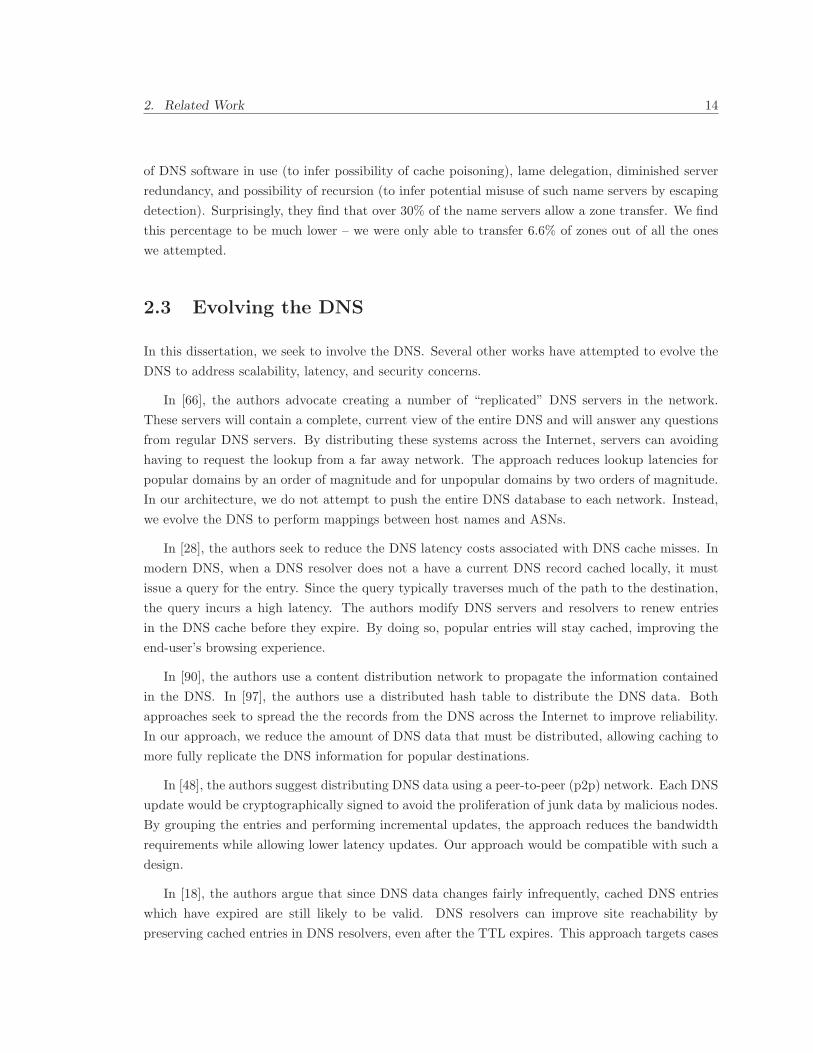
3.6 IPv6 memory requirements under varying FIB sizes . . . . . . . . . . . . . . . . . . . 28
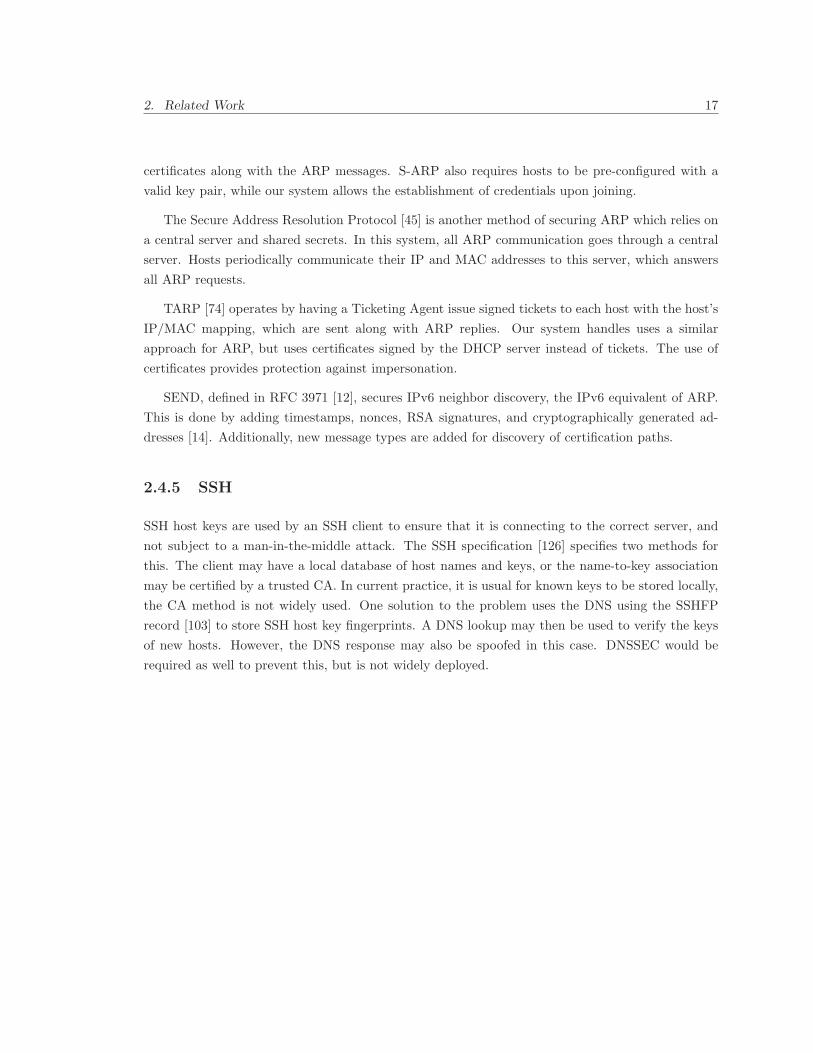
3.7 Lookup times when IPv4 and IPv6 contribute various percentages of the FIB (200,000
prefixes) . . . . . . . . . . . . . . . . . . . . . . . . . . . . . . . . . . . . . . . . . . . 28
3.8 Memory required when IPv4 and IPv6 contribute various percentages of the FIB
(200,000 prefixes) . . . . . . . . . . . . . . . . . . . . . . . . . . . . . . . . . . . . . . 29
3.9 Impact of deaggregation on lookup times of IPv6 tables (200,000 prefixes) . . . . . . 30
4.1 CDFs for distribution of lookup times for name-based and IPv4 approaches . . . . . 37
4.2 Cumulative distribution function for domain popularity . . . . . . . . . . . . . . . . 39
4.3 Comparison of CDFs for lookups in name-based path-compressed tries with and with-
out caching . . . . . . . . . . . . . . . . . . . . . . . . . . . . . . . . . . . . . . . . . 40
4.4 CDF of the percentage of hosts with given number of characters . . . . . . . . . . . 40
5.1 Number of DNS zones containing popular record types (log scale) . . . . . . . . . . . 46
5.2 Number of A records per zone in the combined data set (log-log scale) . . . . . . . . 47
6.1 Cumulative distribution functions showing Web servers per IP address as a percentage
of IP addresses and Web servers . . . . . . . . . . . . . . . . . . . . . . . . . . . . . 53
x

LIST OF FIGURES xi
6.2 Cumulative distribution functions showing Web servers per AS as a percentage of
ASes and Web servers . . . . . . . . . . . . . . . . . . . . . . . . . . . . . . . . . . . 54
6.3 Cumulative distribution functions showing domains per DNS server and domains with
authoritative DNS servers per AS . . . . . . . . . . . . . . . . . . . . . . . . . . . . . 56
6.4 Percentage of domains with the indicated number of DNS servers . . . . . . . . . . . 56
8.1 An example scenario . . . . . . . . . . . . . . . . . . . . . . . . . . . . . . . . . . . . 68
8.2 Name-based routing header (shaded region represents an example locator header) . . 69
8.3 CDF of the percentage of DNS queries for top percentages of domains . . . . . . . . 75
8.4 Example instance of asymmetric addressing . . . . . . . . . . . . . . . . . . . . . . . 78
8.5 Network stacks used in asymmetric addressing . . . . . . . . . . . . . . . . . . . . . 79
9.1 Example certificate chain hierarchy . . . . . . . . . . . . . . . . . . . . . . . . . . . . 86
9.2 Traditional DHCP protocol compared to our secured DHCP implementation . . . . 87
9.3 Example of a certificate under our approach . . . . . . . . . . . . . . . . . . . . . . . 89

Bibliographic References
Material from Chapter 3 appears in a paper co-authored with Minaxi Gupta [105]. Material from
Chapter 4 appears in a paper co-authored with Minaxi Gupta [104]. The material in Chapter 5
is currently under submission in work co-authored with Andrew J. Kalafut and Minaxi Gupta.
The material in Chapter 6 appears in a paper co-authored with Andrew J. Kalafut and Minaxi
Gupta [106]. Material in Chapters 7, 8, and 9 is current under submission.
xii
1
Introduction
The Internet has evolved from a small network of research machines into a world-wide network for
sharing information. The importance of the Internet on commerce, industry, and education has
become so profound that world leaders have labeled Internet access as a vital utility. With such a
vitally important role, network researchers must ensure that the Internet is able to expand and scale
to serve the needs of the generations to come. To do so, we must overcome several difficult technical
obstacles, such as address space exhaustion and decreased routing scalability.
From a structural standpoint, the Internet simply links networks of computers. These networks
may be composed of extremely different types of machines (hosts), communication links, and under-
lying protocols. For example, a host on a wireless network may use radios and the 802.11g protocol
to communicate with another host on a network that uses optical cables and Ethernet as the under-
lying protocol. These hosts may be running different operating systems, such as Windows or Linux.
The goal of internetworking is to allow heterogenous hosts on diverse networks to communicate with
each other. The protocol that makes internetworking possible is the Internet Protocol version 4
(IPv4 ). IPv4 accomplishes this goal by providing a uniform addressing scheme. Applications use
IPv4 addresses to send small groups of information, called packets, to each other. Each IPv4 packet
has 4-byte sender and receiver addresses. The routers in the Internet use the destination address to
forward packets towards their destination.
A collection of contiguously assigned IP addresses are referred to as a prefix. Each organization
that wishes to connect to the Internet must acquire one or more IPv4 prefixes. All hosts within the
organization’s domain must derive their addresses out of the organization’s prefix ranges. Prefixes
make it possible to do efficient routing since a router can use a single prefix entry to represent many
machines. Without such aggregation, routers would have to store a unique entry for each of the
approximately 4.3 billion possible IP addresses, which would make it impossible to forward packets
fast enough to keep up with demand.
While IPv4 addresses are carefully designed to ensure routing scalability, they lack any semantic
1

1. Introduction 2
value, making them difficult for humans to use and remember. Mnemonic host names eliminate
this shortcoming, yet routers only understand IPv4 addresses. Accordingly, host names must be
translated to IP addresses. The Domain Name System (DNS) provides this mapping scalably. As
an example, when a user types www.google.com in a Web browser, the DNS will translate it to one
of Google’s Web servers, say 74.125.95.104, allowing communication to take place. Together, the
IP and DNS are critical infrastructure for typical Internet usage.
Several pressing issues surround routing and addressing that threaten the viability of the con-
tinued expansion of the Internet. The two primary ones are:
• We are running out of IPv4 address space: The shortage of address space in IPv4 has
long been recognized by the community. In theory, the IPv4 address space can be allocated to
232 (approximately 4.3 billion) hosts. However, in practice, imperfect prefix allocation causes
significantly fewer addresses to be usable. Even if every IPv4 address were to be allocated,
this space will not be sufficient given that the world population is reaching 6.5 billion and that
many users possess multiple Internet-enabled devices. This limitation led to the development
of Internet Protocol version 6 (IPv6) [32], which uses 128 bits for host addresses. This allows
2128 (about 3.4× 1038) hosts to be uniquely identified. Unfortunately, the IPv6 adoption rate
has been far from stellar. According to the Route Views Project [120], which allows us to
see the number of prefixes used in the Internet, about 224, 148 IPv4 prefixes were in use in
Internet routing tables in January 2007. During that same month, only 807 IPv6 prefixes were
used, representing less than 0.4% of the IPv4 usage and indicating that few organizations use
it. Therefore, we must investigate alternative addressing schemes that offer greater benefits in
the context of other Internet concerns, especially the one we discuss next.
• The routers may soon be unable to forward packets at nanosecond speeds: To
meet modern bandwidth requirements, routers must be able to forward each packet in tens to
hundreds of nanoseconds. To do so, routers must store all the IP prefixes in high-speed memory,
typically Static Random Access Memory (SRAM). Unfortunately, high-speed routers are a
low-volume niche market without the economies of scale required to drive capacity increases
in SRAM memory [77]. With slow SRAM capacity growth, the alarming rate of growth in
IPv4 prefixes may soon make it impossible for the routers to keep up with the required packet
forwarding speeds [77]. The severity of the problem can be seen in the exponential growth in
the number of prefixes handled by modern routers in the core of the Internet. Specifically, there
were fewer than 50, 000 IPv4 prefixes in 1997. Five years later, in 2002, this more than doubled
to 113, 614 prefixes. The prefixes again nearly doubled in the next five years with routers
handling 224, 148 prefixes in 2007. With the larger address space of IPv6, these concerns are
expected to become ever more acute. In particular, our own measurements indicate that the
expanded address space of IPv6 comes at a premium, requiring more time to forward packets
and more memory to store the prefixes [105].

1. Introduction 3
The research community has been actively pursuing solutions to each of the above problems. For
example, the work by Subramanian et al. [115] proposed a scalable alternative to the Border Gateway
Protocol (BGP), the Internet routing protocol used to route packets in the core of the Internet.
Similarly, the work by Francis et al. [44] used Network Address Translation (NAT) to solve address
exhaustion. In the work by Caesar et al. [24], the authors explored replacing host addresses with
flat labels, which offer practically unlimited addresses, to determine if such an approach would scale.
Though differing in their goals, the common thread across these examples is that they trade concerns
of immediate deployment for long term benefits and in turn require fundamental changes to the key
protocols used by the Internet entities. Unfortunately, none of these proposals provides a holistic
solution. In this dissertation, we develop an architecture that provides a comprehensive solution to
the addressing and routing scalability concerns, leveraging these previous works on occasion. Our
architecture has the following properties:
1. Solves Address Space Exhaustion: Our architecture solves address exhaustion concerns
and provides an even larger address space than IPv6. The key aspect of our architecture that
makes this possible is that it uses fully qualified domain names (for simplicity, we refer to these
as host names or names subsequently) to identify hosts. While IPv6 offers 2128 addresses, we
offer 37255 addresses, orders of magnitude more.
2. Ensures Scalability of Packet Forwarding: Host names solve address exhaustion concerns
but do not lend themselves to scalable routing because they far exceed the number of IPv4
prefixes. Specifically, in January 2007, there were 224, 148 IPv4 prefixes. In contrast, there
were 128 million domains at that time with many hosts in each domain [123]. We translate host
names into a small number of routing locators to ensure high-performance packet forwarding.
The routing locators reduce router memory requirements, allowing faster packet forwarding
speeds than today’s IPv4 while ensuring scalability for decades to come.
3. Embraces Evolution of Host Addressing: The separation of routing from host identifi-
cation allows our architecture to support multiple addressing schemes for end hosts without
requiring modifications to the core Internet routing. This is useful in the light of other special-
purpose addressing schemes, such as HIP [81], which provides strong host authenticity, or
FARA [27] and i3 [114], which focus on host mobility.
4. Supports Unified Intra-Domain Security: Intra-domain protocols, such as Dynamic Host
Control Protocol (DHCP), suffer from various security concerns. Even though solutions exist
for individual protocols, no solution provides support across intra-domain protocols. Recog-
nizing that a mechanism to authenticate each host would provide a fundamental building block
for addressing intra-domain security concerns, we tie host names to cryptographic credentials
called certificates. The certificate uniquely identifies each host, preventing impersonation. We
then use well-known cryptographic operations to provide a unified framework for intra-domain
security.

1. Introduction 4
Our architecture is based on the observation that most hosts in the Internet have two identifiers
associated with them: IP addresses and host names. We question whether this redundancy is
necessary. Since IP addresses are not human-friendly, we began our exploration with the idea of using
only host names as addresses for hosts. This concept is attractive on many counts. First, it offers a
large address space: DNS host names can be up to 255 characters long, with acceptable characters
including letters, numbers, and hyphens. This allows 37255 possible host names as compared to the
2128 available under IPv6. Second, this scheme requires no change on the part of Internet users, who
are accustomed to referring to servers by their names. Third, eliminating the translation from host
names to IP addresses eliminates DNS lookup overheads and the possibility for mapping errors. We
envisioned an Internet where end hosts are addressed simply by names and routers forward packets
based on the name of the destination. Initially, it seemed that this would support routing scalability
because, just as IPv4 addresses are aggregated into prefixes, host names can be aggregated into the
domains in which they belong. When we evaluated this architecture by examining the scalability of
packet forwarding, we found that host names could cost the routers up to three times more packet
forwarding time and one to two orders of magnitude more memory to store the routing tables. These
results were not surprising given that there were 224, 148 IP prefixes and three orders of magnitude
more (128 million) domains in 2007. However, we had hoped that some optimizations, including
caching the most popular domain names at local routers, would help. In the end, we concluded that
while host names are useful for host identification, they are insufficient for routing.
Next, we looked for alternatives to scale Internet routing when names were used to identify
end hosts. We leaned on locator-identifier separation, an approach the networking community has
recently explored to curtail growth in IPv4 prefixes. The basic idea behind this approach is to
translate host identifiers to routing locators at the point where packets enter the network. The
routers in the core of the Internet forward packets only on routing locators. The scalability of this
approach stems from the expectation that there will be far fewer locators than host identifiers and
that the locators will be immune to factors that cause growth in the routing tables today. As an
example of the factors that cause growth in the number of IPv4 prefixes, many organizations today
split their IPv4 prefixes in an attempt to receive traffic over multiple links. This technique, called
load balancing, causes multiple prefixes to exist in the routing table where there would only have been
one. This increases the load on all routers in the Internet. Similarly, an organization may acquire
its prefix range from its provider ISP and then choose to have another provider ISP, for increased
availability under link failures. This practice, called multi-homing, causes an increase in the number
of prefixes in all routers because the new provider ISP cannot aggregate the organization’s prefix
with its own. Today, load balancing and multi-homing are significant contributors to routing table
growth [23]. In particular, multi-homing is the biggest cause for concern about routing scalability
today.
A key issue in leveraging the locator-identifier separation concept is the choice of a locator.
In this dissertation, we examine the identifiers already used by networks in modern routing in

1. Introduction 5
order to pick an adequate locator. Specifically, networks controlled by a single administrative entity,
called Autonomous Systems (ASes), are associated with a unique identifier, the Autonomous System
Number (ASN). The ASN is used by the inter-domain routing protocol, BGP, to avoid accidentally
sending packets into endless loops between routers. The ASNs have two properties that make them
attractive as routing locators. First, there are an order of magnitude fewer ASNs than IP prefixes.
According to the Route Views Project [120], just over 25,000 ASNs were represented in the BGP
routing announcements in an April 2007 snapshot of BGP data1. In contrast, 233, 500 unique IPv4
prefixes were present in BGP routing tables. Second, the fixed length of the ASNs is amenable to
faster lookup algorithms, unlike IP prefixes that require a more expensive longest prefix match.
We find that if a router were to forward packets on ASNs, packet forwarding would be an order of
magnitude faster than IPv4. Further, the routers would require less than one-third of the memory
required for IPv4 forwarding. We conclude that our architecture will solve address exhaustion
concerns in the Internet while making routing in the core of the Internet an order of magnitude
faster than today. However, before ASNs can be adopted, we must carefully address the issue of
ASN growth. Specifically, we must ascertain that the factors that cause exponential growth in IPv4
prefixes would not hurt the future scalability of our scheme. Upon examining this aspect in detail,
we find that ASNs would be less susceptible to the growth factors in IPv4, indicating that they will
continue to scale Internet routing for decades to come.
In pursuing this architecture, we must have cooperation from the Internet stake-holders. To
support ASN and host-based lookups, router manufacturers must update the protocols used by their
routers and redesign the hardware used in packet forwarding. In turn, Internet Service Providers
(ISPs) must adopt the newly-designed routers. Further, operating system vendors must update
their network stacks to enable end-host support for the new packet headers. In order to enable such
large-scale cooperation, we must focus on incentives and techniques to cope with partial deployment.
ASN-based routing allows for faster packet forwarding at the routers without expensive hardware.
The reduced hardware costs and motivation from routing vendors to bring routers that can route
on ASNs to market will be critical to adoption. Once a core locator infrastructure is in place,
organizations can avoid address exhaustion concerns by upgrading their hosts to support name-
based headers. While in transition, our architecture supports several partial deployment strategies
to ensure proper interaction with legacy networks and hosts.
1.1 Dissertation Road-map
We organize the content of this dissertation in the following four components. Some of these com-
ponents span multiple chapters.
1The total number of ASNs allocated to different organizations worldwide stands at around 39,000 [95].
1. Introduction 6
1.1.1 IPv6 Scalability
With concerns about the performance of IPv6 routing, we examine how IPv6 would perform if it
were widely deployed. To do so, we create software implementations of popular lookup algorithms
used by routers and compare the performance and memory requirements of IPv4 with IPv6. We
additionally simulate a growth in the number of IPv6 and analyze the impact of other growth
factors, such as multi-homing and load balancing, on IPv6. We find that modern lookup algorithms
are ill-suited for IPv6, yielding steep performance degradation and memory overheads. We then
tailor an existing algorithm to lessen these overheads in deploying IPv6 with some success. In spite
of this enhancement, we find the performance and memory requirements of IPv6 to be worse than
IPv4 in all our measurements. In particular, the best algorithm for IPv6 still requires 8% more
time to perform lookups and 45% more memory than an equivalent operation in IPv4. We conclude
that while IPv6 solves the address space crisis, it does so at the cost of worse packet forwarding
performance and increased router memory consumption.
1.1.2 Routing on Host Names
Next, we examine the scalability of packet forwarding when end-hosts are identified by their names
instead of IP addresses. We create software implementations of popular forwarding algorithms for
both IP and host names and record the forwarding times and the amount of memory required by
each approach. In constructing the forwarding table, we aggregate host names into their domains to
reduce the number of entries required. We find that even on a small number of domains, IPv4 per-
formance greatly exceeds the performance we get on host names. Further, the memory requirements
for forwarding tables based on host names exceed the memory capacity of routers. While we explore
approaches to attempt to reduce these requirements, we conclude that forwarding packets directly
on host names is not a viable approach.
In the above experiments, we assumed that host names could be aggregated into domains. For
example, the host names www.cs.indiana.edu and www.informatics.indiana.edu can both be
aggregated as indiana.edu because they are co-located at indiana.edu. This aggregation would
reduce memory requirements at the routers. However, this aggregation may not always be possible.
For example, us.ibm.com and asia.ibm.com cannot be aggregated into ibm.com because they are
topologically separated with different routing paths. This is a big concern for routing based on
host names because with the latter case a single entry for a domain would be unable describe the
routes for all the hosts. Upon exploring this issue further, we find that, in practice, all hosts in most
domains do tend to topologically close to each other. However, there are striking exceptions: some
domains have hosts from thousands of different networks in the Internet. Overall, we conclude that
domain aggregation for hosts is generally feasible but note that we must still support domains where
such aggregation is infeasible.

1. Introduction 7
1.1.3 Separating Routing from Host Identification
Realizing that host names have desirable properties but are unsuitable for routing, we explore
approaches to scale routing. While separating routing locators from host identifiers is a compelling
concept, we need to evaluate whether ASNs would make a good locator in practice. We begin
by modeling ASN growth to ascertain their feasibility for decades to come. We examine routing
tables to look at the impact of multi-homing and load balancing on the growth of ASNs. We
find that many ASNs today exist solely to participate in BGP when multi-homed. Our architecture
eliminates the need for such ASNs, curbing growth in ASNs and reducing the number of entries
routers must maintain and consult during packet forwarding. We further evolve the DNS in our
architecture in a way that load balancing does not cause any growth in routing tables. We then
use software implementations of forwarding algorithms to compare ASN-based forwarding and IPv4-
based forwarding. We find that ASN-based packet forwarding is an order of magnitude faster than
IPv4-based forwarding and requires less than 30% of the memory required for IPv4 forwarding.
Beyond examining the suitability of ASNs as locators, this component of the dissertation makes
two other contributions. First, we propose a unified architecture that identifies end-hosts with
host names and uses ASNs as routing locators. We examine the impact of the changes required to
translate from the current Internet architecture to the one we propose. We develop techniques and
strategies for partial deployment, in which the current and proposed architectures interact. We find
that packets under our architecture will get bigger because they will have to contain host names,
which are long, as against shorter IPv4 addresses. However, we conclude that the gains in routing
performance more than make up for the increase in packet size.
The second contribution of this component is the exploration of who should do the mapping
from host names to routing locators. We examine two approaches. In the first, hosts perform a
name to ASN lookup, much like how they today perform a host name to IP address lookup. The
DNS in this approach requires a change in that it must provide ASN records instead of IP addresses
when queried. However, this approach does not require any support from routers beyond being
able to route on ASNs instead of IPv4 prefixes. The second approach is for routers to perform the
translation through an independent database. This requires a new infrastructure component to aid
routing and may raise new security issues. We conclude that the approach where hosts perform the
mapping from names to ASNs has several compelling advantages: it is simple, the DNS has proven
to be a scalable approach, and the performance overheads can be predicted using DNS measurements.
1.1.4 Intra-domain Security
Lack of authentication is a significant security concern today: if we can correctly verify a host
or server is who it claims to be, we can prevent impersonation attacks. In current intra-domain
protocols, such as the DHCP, the protocol used to automatically configure hosts when they connect
1. Introduction 8
to the network, no authentication is provided, leaving hosts vulnerable to attacks. In one type of
attack, a machine can impersonate a DHCP server and provide other machines on the network with
false information, allowing the impersonator to intercept or forge data. In another attack, a single
machine can impersonate many different machines and overwhelm the resources at a legitimate
DHCP server, preventing other clients from getting configured correctly. A few works attempt to
address the security weaknesses in DHCP while other works focus on other intra-domain protocols.
None of these works provide a general way to address these intra-domain security concerns across
protocols. In our architecture, we provide a seamless mechanism to authenticate hosts. In particular,
our architecture identifies machines solely by their host names. Users can examine the host names
to confirm that they are communicating with the intended organization. We then tie these host
names to cryptographic credentials, called certificates, which can then be used to automatically
authenticate hosts and networks.
Specifically, we create a scheme that can secure intra-domain protocols in a unified way. To do
so, we create a scheme where a centralized server verifies the authenticity of hosts and issues crypto-
graphic certificates, allowing each host to prove its authenticity to others. To evaluate this approach,
we focused on two intra-domain protocols: DHCP and Address Resolution Protocol (ARP). We al-
tered the protocols to incorporate the certificates and cryptographic primatives required to allow
hosts to strongly authenticate themselves. We measured the overheads introduced in these protocols
using timing operations and used campus network profiles to determine whether this load would be
acceptable on the network infrastructure. Upon analyzing these protocols, we found that the in-
creased load would be greatest on network routers and switches. However, even for these devices,
we found that the overheads for each system are acceptable for both small and larger intra-domain
networks.
The rest of this dissertation is structured as follows. We review related work in Chapter 2. In
Chapter 3, we examine the scalability of IPv6, a proposed replacement for IPv4. In Chapter 4, we
examine the feasibility of using DNS host names as identifiers for hosts and as routing locators.
In Chapter 5, we examine how DNS zones relate to network topology. In Chapter 6, we examine
whether multiple domains can be aggregated to reduce router memory requirements. In Chapter 7,
we examine whether ASNs could be used as a routing locator in a split locator-identifier scheme. In
Chapter 8, we describe a unified architecture that integrates ASNs as routing locators and DNS host
names as host identifiers. In Chapter 9, we describe how confidentiality and authentication services
could be granted for hosts in such an architecture. In Chapter 10, we conclude with discussion.

2
Related Work
Our architecture is connected to an extensive set of related work. For readability, we divide the
related work into sections: new Internet architectures, Web and Domain Name System (DNS)
measurements, work to evolve the DNS, and work to secure intra-domain protocols. We now describe
each in greater detail.
2.1 New Internet Architectures
With the limitations present in IPv4, the networking community has explored a number of different
avenues for fundamentally changing the Internet architecture to address these shortcomings.
TRIAD [46] was the first architecture to explore the idea of name-based routing. Their goal was
to make Web content, specifically Uniform Resource Locators (URLs), accessible through router
participation. They use names and URLs for end-to-end identification and use IPv4 to tunnel
between their enhanced routers. While names are a component of TRIAD addressing, the usage of
a full URL allows them to better serve Web content. The DNS operation is altered in the TRIAD
scheme; resolution requests and Transmission Control Protocol (TCP) connection establishment are
combined into a single step. Each router directs the establishment packet by looking up the name
and directing the packet along the path to the described destination and including a source route
to the destination. The destination establishes TCP state and replies to the source, allowing the
source to reach the destination. Unlike our scheme, TRIAD does not focus on address exhaustion
or routing scalability issues.
IPNL [44] was designed to embrace Network Address Translation (NAT) to provide greater
address expansion in the Internet. NAT has historically been viewed as an obstacle in the Internet
because it breaks the notion of an end-to-end connection. Further, the stateful nature of NAT
makes it less scalable and can limit the ability of systems behind the NAT to act as servers. In the
9

2. Related Work 10
IPNL work, the authors wanted to ease deployment by avoiding changes to the Internet core and
thus leverage IPv4 in their design. IPNL uses fully qualified domain names as end-host identifiers.
End-hosts include these names in their connection establishment packets. IPNL routers perform
DNS queries on these host names to determine the address of the next IPNL router. Each IPNL
router records its address in the packet header. When the packet arrives at the destination, the
destination machine can reply by reversing the path of IPNL router addresses, which will loosely
route the packets back to the source. Subsequent packets omit host names and simply use the source
route path for transmission. Unlike IPNL, our architecture eliminates the need for the DNS and the
usage of the IP network layer. Further, by using Autonomous System Numbers (ASNs) in a layer,
we enhance scalability across the core of the Internet, a feature that IPNL does not provide.
IPv6 [32] makes a number of changes from IPv4. While its primary goal was to increase the
address space available to end-hosts, other changes were also introduced since the widespread changes
required for adoption allowed the community to address other issues as well. IPv6 has been the
subject of a number of Internet Engineering Task Force (IETF) Request for Comments (RFCs)
which specify the details of the protocol. A recent RFC [51] specifies the format of the IPv6
addresses and address allocation. Another RFC [56] provides advice from the Internet Architecture
Board (IAB) to the Internet registries on allocating globally aggregatable prefixes. When examining
IPv6, we focus on this allocation scheme as it is the most authoritative recommendation available.
While IPv6 is successful in expanding the address space available to end-hosts, it does not provide
a complete solution: it does not address routing scalability [77] or allow for the future evolution of
the Internet.
SNF [61] introduces an abstract framework in which the network layer is split into a forwarding
layer and a naming layer. The framework was designed to be as generic as possible to ensure
flexibility. The framework intentionally avoids details, so it simply provides guidance for future
works. Our approach extends this work by merging DNS and routing infrastructure for routing
directly using DNS names.
Several proposals aim to separate routing locators from end-host identifiers. We refer to such
proposals as locator-identifier split proposals throughout this paper. In these proposals, the router
close to customer edge looks up the locator for the destination address using a mapping database.
The router then uses the locators for source and destination hosts to populate an encapsulation
header, which is placed at the front of the original packet. Due to the mapping and encapsulation
involved, this is often referred to as a map-and-encap approach. The routing scalability of these
approaches stems from the fact that they allow routers in the core of the Internet to forward packets
only based on the locators, which are fewer in number, facilitating smaller forwarding tables. When
an encapsulated packet arrives at the destination edge network, the router removes the encapsulation
and sends the packet on to the host indicated in the original packet. The intra-domain routing
functions in a manner similar to today in each of these proposals. In NIMROD [25], encapsulation
is used to avoid complexity in the core of the Internet and to perform a locator-ID split. In the

2. Related Work 11
NIMROD architecture, routers use IPv6 addresses with 32 bit locator addresses, allowing multiple
locators to be specified in a single address. In ENCAPS [50] and CRIO [127], encapsulation is
used to reduce routing table sizes while operating on existing infrastructure. ENCAPS, which
was designed as a temporary measure, requires the first ENCAPS router to perform DNS lookups
on incoming packets in order to find a single address that represents the destination autonomous
domain. That router must then encapsulate the original packet in another IP packet with the address
that represents that domain. The CRIO work uses IP-in-IP, MPLS, or GRE encapsulation, but
establishes one-way tunnels between points of presence (POP). Since there are far fewer POPs, with
widespread CRIO deployment, routers in the default-free zone would only have to store one entry
for each POP, reducing routing table sizes. In LISP [40], the authors strive to decrease routing table
sizes but also try to incorporate support for mobility. To do so, they encapsulate packets for inter-
domain transport and de-capsulate packets when they reach the destination system. NERD [72], a
push-based database suite, augments LISP by providing both a format and mechanism for mapping
identifiers to locators. Like NERD, APT [60] defines a mapping service; however, APT is focused on
providing services for the eFIT approach [75]. In eFIT the authors suggest separating the address
space for end-hosts and routers to improve multi-homing and routing scalability. In our work, we
examine whether ASNs provide suitable routing locators which may influence the selection of locators
in these schemes and subsequent proposals.
The compact routing field has evaluated the long-term scalability of many routing approaches.
In the work by Krioukov et al. [71], the authors note that ASes are a natural choice for locators
and that there are an order of magnitude fewer ASes than the number of announced prefixes. The
transition to ASNs would immediately reduce forwarding tables by an order of magnitude, which
would relieve our current concerns about router forwarding table capacity. However, the authors
caution that this could be simply a one-time benefit and indicate that the rate of growth of ASes
exceeds that of IP prefixes. While raising this concern, the authors did not examine the causes of this
AS growth. However, upon considering the causes of growth, we find that under a split locator and
identifier scheme that uses ASNs several growth factors would be eliminated, slowing ASN growth.
Further, the Krioukov work also indicates the mapping from identifiers to locators requires a global
distributed mapping database, reducing scalability. However, a pull-based database, such as the
DNS, can perform these mappings in a scalable manner. Accordingly, we believe locator-ID schemes
still merit consideration.
HLP [115] is a routing protocol that improves inter-domain routing scalability. HLP improves
scalability in two ways. First, it hides minor routing changes from distant ASes which improves
fault isolation and reduces the scope of update messages. Next, HLP sends routing messages at
the Autonomous System (AS) granularity, allowing routers to update the reachability of multiple
co-located prefixes with a single message rather than requiring an update message for each prefix.
By reducing the number of update messages, HLP aids route convergence. In our architecture, we
can leverage HLP for better fault isolation and convergence properties.

2. Related Work 12
GIRO [86] seeks to improve the shortest path algorithms used by inter-domain routing. Currently,
the path length in terms of ASNs plays a pivotal role in route selection in Border Gateway Protocol
(BGP) routers. Unfortunately, the shortest AS path may not be the shortest physical path to a
destination. To combat this problem, the authors suggest redesigning routing, packet forwarding,
and the packet header to indicate the geographical location of the destination. In doing so, they
use the ASN as a component in their addressing scheme. The role of the ASN in their addressing is
simply as a provider identifier for aggregation. This scheme seeks only to influence route selection,
ignoring any issues related to end-host identification.
The work in AIP [5, 7] shows the security benefits of incorporating provider network information
in packets. The architecture endorses the usage of an “autonomous domain,” which is a region
smaller than an AS. While this work focuses on accountability, it is compatible with our own and
highlights the potential of the direction.
Other work in Internet architecture is relevant, but not as closely related. The work in [43]
compares schemes based on geographical location with schemes that use the Internet Service Provider
(ISP) hierarchy. The work concluded that the latter approach is a more scalable design. FARA [27]
and i3 [114] focus on mobility and utilize rendezvous mechanisms to facilitate communication between
mobile hosts. In HIP [81], the authors use public key cryptography to create secure identities for
end-hosts, an approach compatible with our own. The work in [2] extends the HIP scheme by
creating node identifier domains to make the scheme more scalable. In Layered Naming [17], the
authors use separate identifiers to distinguish between services and hosts, allowing for the delegation
of duties, which benefits traffic engineering. In NIRA [125], the authors discuss the feasibility of
allowing end-hosts to select which networks their packets use for transit, unlike traditional routing
in which routers select the paths. Finally, in ROFL [24], the authors demonstrate that flat address
spaces may be feasible for routing. In our architecture, the ASN layer’s fields have flat addresses.
However, unlike in ROFL, routers in our architecture can independently make forwarding decisions
for the packets.
Other works provide insights on the design of next generation architectures. In [6], the authors
propose using resilient overlay networks (RONs) to increase reliability for end-hosts. In this system,
end-hosts join small overlay networks which have diverse network vantage points, generally allowing
hosts to reach a destination assuming any physical connection exists to the destination. In [41], the
authors advocate using a Routing Control Platform in each autonomous system to make routing
decisions for each inter-domain router, simplifying configuration and reducing router inconsistencies.
In [98], the authors survey current architecture design options and implications, with a focus on
allowing future evolution of the Internet. In [4], the authors propose a routing architecture where
overlay networks perform their own routing for above layers. In [42], the authors advocate separation
of infrastructure providers from service providers by creating virtual networks and allowing multiple
architectures to run on the same infrastructure.

2. Related Work 13
2.2 Web and DNS Measurements
In proposing a new architecture, we must examine the current Internet use-cases and determine
whether our new design can accommodate them. To do so, we perform a series of Web and DNS
measurements.
A number of works have looked at the Web from the perspective of documents that comprise it.
In [3], the authors use connectivity measurements to learn about the topology of the Web. Work
in [85] examines how search engines should deal with the evolution of the Web. In [31], the authors
demonstrate that Web traffic exhibits a high degree of self-similarity, much like wide-area and local
area network traffic. In [21], the authors determine that while Web access does not exactly follow
a Zipf distribution, simple Zipf-like models are sufficiently accurate for Web proxies. In [19], the
authors examine methods for generating representative Web traffic. Work in [13] examines Web
traffic using six data sets and suggests performance enhancements for Web servers. In our work, we
examine the Web using the infrastructure hosting these sites rather than the content of the Web
itself.
Pang et al. perform an extensive analysis on the DNS infrastructure [88]. Their work focuses on
the availability of name servers, whereas ours examines the characteristics of the domains themselves.
Edelman examines the number of Web sites hosted on the same IP address [36]. The motivation
for this work was to determine the extent of collateral damage from IP-based filtering. However,
because the work was focused on the societal impact of the practice, it does not provide a rigorous
discussion of the technical details.
Other work focuses on the DNS infrastructure. Wanrooij et al. [121], characterized DNS miscon-
figurations from a sample of the .NL TLD. They did so by performing DNS ANY queries on 10,000
randomly zones mentioned in the .NL zone file. Their study had limited view of DNS provisioning
because the ANY query, as they used, provides only a small subset of the records in a zone. Our
analysis on DNS zones considers extensive information about orders of magnitude more domains
and provides details not exposed in this work.
Pappas et al. [89] examined the impact of three specific DNS configuration errors: lame delegation
(the name server(s) present at the zone differ from those present at the parent zone), diminished
server redundancy (less than adequate number of name servers are available or the available servers
are not topologically dispersed, implying that they may become unavailable under attack or outage
conditions), and cyclic dependency (name servers point to each other, forming a loop). Our work
focuses on domain availably, breadth, and size and uses a different methodology.
The Measurement Factory [118] recently performed zone transfers on a small fraction of the .com
and .net zones. They randomly sampled about 3.22% of .com and .net zones and attempted to
transfer them. Though they had data similar to us, they utilized it in ways that differ significantly
from us. While we focus on information contained in zone records, they focused on the versions
2. Related Work 14
of DNS software in use (to infer possibility of cache poisoning), lame delegation, diminished server
redundancy, and possibility of recursion (to infer potential misuse of such name servers by escaping
detection). Surprisingly, they find that over 30% of the name servers allow a zone transfer. We find
this percentage to be much lower – we were only able to transfer 6.6% of zones out of all the ones
we attempted.
2.3 Evolving the DNS
In this dissertation, we seek to involve the DNS. Several other works have attempted to evolve the
DNS to address scalability, latency, and security concerns.
In [66], the authors advocate creating a number of “replicated” DNS servers in the network.
These servers will contain a complete, current view of the entire DNS and will answer any questions
from regular DNS servers. By distributing these systems across the Internet, servers can avoiding
having to request the lookup from a far away network. The approach reduces lookup latencies for
popular domains by an order of magnitude and for unpopular domains by two orders of magnitude.
In our architecture, we do not attempt to push the entire DNS database to each network. Instead,
we evolve the DNS to perform mappings between host names and ASNs.
In [28], the authors seek to reduce the DNS latency costs associated with DNS cache misses. In
modern DNS, when a DNS resolver does not a have a current DNS record cached locally, it must
issue a query for the entry. Since the query typically traverses much of the path to the destination,
the query incurs a high latency. The authors modify DNS servers and resolvers to renew entries
in the DNS cache before they expire. By doing so, popular entries will stay cached, improving the
end-user’s browsing experience.
In [90], the authors use a content distribution network to propagate the information contained
in the DNS. In [97], the authors use a distributed hash table to distribute the DNS data. Both
approaches seek to spread the the records from the DNS across the Internet to improve reliability.
In our approach, we reduce the amount of DNS data that must be distributed, allowing caching to
more fully replicate the DNS information for popular destinations.
In [48], the authors suggest distributing DNS data using a peer-to-peer (p2p) network. Each DNS
update would be cryptographically signed to avoid the proliferation of junk data by malicious nodes.
By grouping the entries and performing incremental updates, the approach reduces the bandwidth
requirements while allowing lower latency updates. Our approach would be compatible with such a
design.
In [18], the authors argue that since DNS data changes fairly infrequently, cached DNS entries
which have expired are still likely to be valid. DNS resolvers can improve site reachability by
preserving cached entries in DNS resolvers, even after the TTL expires. This approach targets cases

2. Related Work 15
where the required DNS servers are temporarily unavailable. Our architecture may support this
approach since fewer records would be required and would be more stable, reducing the accumulation
of invalid entries.
In [11], the authors introduce DNS Security Extensions (DNSSEC), an approach for crypto-
graphically authenticating the records in the DNS. Resolvers following the DNSSEC protocol can
use a series of public key operations to verify the authenticity of the data received from DNS servers.
DNSSEC is compatible with our approach. Further, since fewer records are required, the overheads
for DNSSEC may be lower in our architecture.
In [47], the authors describe privacy short-comings in the DNS when it is used as a solution
for host mobility. They argue that many users sign up for dynamic DNS host names to facilitate
reaching their own machines. However, this approach also allows an attacker to watch the user’s
movements. An attacker can resolve the dynamic DNS host name to an IP address and then perform
a reverse DNS lookup on the IP to get the ISP provided host name associated with the IP address.
By feeding the ISP’s host name into WHOIS or other geographical location databases, the attacker
can learn the victim’s approximate physical location. To address this issue, the authors suggest a
broker to proxy connection requests to the mobile host. The mobile host can send proxied challenges
to the connecting system before revealing its IP address. When developing a mobility solution for
our architecture, we must be mindful of this issue.
2.4 Intra-domain Security
While no previous work provides a unified approach address all of the intra-domain security issues,
many of these concerns have been addressed individually in prior work. We discuss related work on
these issues, and work addressing other aspects of intra-domain security.
2.4.1 DHCP
Two RFCs address the issue of authentication in DHCP. RFC 3118 [34] defines an option for DHCP
which provides authentication and replay detection using shared secrets. This method does not
protect the portions of the communication which may be added by a DHCP relay; however, [112]
provides this protection. Another system, UA-DHCP [70], adds user authentication to DHCP. By
requiring the user to supply a username and password, this system provides access control to the
network, but still allows legitimate users access to the network from any machine without requiring
MAC address registration. It also prevents unauthorized users from gaining access by replicating
a legitimate MAC address. While these approaches provide access control and authentication to
DHCP, they do not provide a means for the machines in the domain to authenticate each other. In
our scheme, we provide each machine with a certificate to prove its authenticity. The method in

2. Related Work 16
RFC 3118 additionally requires the server to have established a shared secret with each client out of
band, which may be impractical if there is a large number of clients. In our scheme, organizations
can image their machines to pre-load them with the domain public key or simply distribute a patch
to the machines to load the key, simplifying administration.
In [15], authenticated DHCP is used as a way of providing authenticated network location aware-
ness information. The DHCP server is authenticated to the user by providing a chain of certificates,
leading from a certificate for the DHCP server up to a trusted root. Our system use a similar
mechanism to authenticate the DHCP server to the user.
2.4.2 Local Network Authentication
Our system requires machines to authenticate to the DHCP server before being allowed network
access. Others, mentioned in Section 2.4.1 similarly leverage DHCP for this purpose. There have
been several other systems proposed and implemented to solve the problem of authentication for
individual machines [20, 94, 9, 16]. The 802.1X standard [57] is supported out of the box by the
current versions of major operating systems, and provides mutual authentication using the Extensible
Authentication Protocol [1]. None of these approaches attempt to secure intra-domain protocols.
2.4.3 Remote Authentication
Several protocols exist for authenticating remote hosts. RADIUS [100] provides authentication, au-
thorization, and configuration information. EAP [1] provides a framework for authentication, allow-
ing the choice between multiple authentication methods, and may be used by RADIUS. CHAP [107],
and its extention MS-CHAP [129, 128], provide authentication by hashing challenges at random in-
tervals using a shared secret. The certificates provided by our system can also be used for remote
authentication.
2.4.4 ARP
One of the techniques to counter ARP insecurities is DHCP snooping [26]. The switches employing
this technique monitor DHCP traffic to create white-lists of MAC address and IP bindings, and
associate them with individual ports. Subsequently, if a packet arriving on a switch interface does
not match the binding, it is discarded. This approach eliminates the possibility of ARP cache
poisoning attacks and IP spoofing.
S-ARP [22] secures ARP by providing each host with a public/private key pair, and using this
to sign each ARP message. We use a similar method for securing ARP, however S-ARP requires
an Authoritative Key Distributor to provide keys for the verification process, while we provide
2. Related Work 17
certificates along with the ARP messages. S-ARP also requires hosts to be pre-configured with a
valid key pair, while our system allows the establishment of credentials upon joining.
The Secure Address Resolution Protocol [45] is another method of securing ARP which relies on
a central server and shared secrets. In this system, all ARP communication goes through a central
server. Hosts periodically communicate their IP and MAC addresses to this server, which answers
all ARP requests.
TARP [74] operates by having a Ticketing Agent issue signed tickets to each host with the host’s
IP/MAC mapping, which are sent along with ARP replies. Our system handles uses a similar
approach for ARP, but uses certificates signed by the DHCP server instead of tickets. The use of
certificates provides protection against impersonation.
SEND, defined in RFC 3971 [12], secures IPv6 neighbor discovery, the IPv6 equivalent of ARP.
This is done by adding timestamps, nonces, RSA signatures, and cryptographically generated ad-
dresses [14]. Additionally, new message types are added for discovery of certification paths.
2.4.5 SSH
SSH host keys are used by an SSH client to ensure that it is connecting to the correct server, and
not subject to a man-in-the-middle attack. The SSH specification [126] specifies two methods for
this. The client may have a local database of host names and keys, or the name-to-key association
may be certified by a trusted CA. In current practice, it is usual for known keys to be stored locally,
the CA method is not widely used. One solution to the problem uses the DNS using the SSHFP
record [103] to store SSH host key fingerprints. A DNS lookup may then be used to verify the keys
of new hosts. However, the DNS response may also be spoofed in this case. DNSSEC would be
required as well to prevent this, but is not widely deployed.

3
IPv6 Scalability
3.1 Introduction
Over 88% of the IPv4 address space had been allocated by spring 2009 [55]. The remaining address
space is projected to be exhausted by April 2011, at which point no more addresses will be available
for new hosts. The Internet Protocol version 6 (IPv6) was designed to solve the impending address
space crisis in IPv4. The 128-bit IPv6 [59] address space provides approximately 5× 1028 addresses
for each of the roughly 6.5 billion people on planet earth. With this much address space, IPv6 is
widely believed to be an answer to IPv4’s address exhaustion concerns. Both researchers and the
United States government [38] have encouraged the adoption of IPv6.
There are still open issues with technical aspects of IPv6 adoption. There are two primary
concerns: 1) the routing table size may be bigger for IPv6, simply because each entry requires four
times more space, and 2) the effect of factors that contribute to IPv4 routing table growth needs
to be examined in IPv6. We examine these growth factors, such as load balancing, multi-homing,
failure to aggregate aggregatable prefixes, and sub-optimal prefix allocations, and how they are
increasing the IPv4 routing table sizes to the point where modern router hardware may soon not be
able to store the table [77]. All of these factors, except for sub-optimal prefix allocations, are likely
to exist for IPv6 and could exacerbate the issue of routing scalability.
In this chapter, we examine the scalability of IPv6 packet forwarding. Routers have to perform a
look up on the destination IP address in each packet to find the appropriate information to route the
packet towards the destination. Router perform this lookup using a longest prefix match algorithm.
We implement the various longest prefix matching algorithms used by routers in software, and
compare the memory requirements and performance of IPv4 and IPv6. To perform this comparison,
we must load the data structures with entries. This is straight-forward for IPv4 since we have
routing tables available. Unfortunately, the situation is different for IPv6 since there are very few
IPv6 prefixes being announced in the Internet. According to the Route Views Project [120], which
18

3. IPv6 Scalability 19
provides BGP routing tables from many vantage points in the Internet, the highest number of IPv6
prefix entries at any vantage point was only 807 in January 2007. Given that the number of entries
in July 2003 was 468, the increase in IPv6 deployment thus far has been far from stellar. In the lack
of a wide-spread deployment, we turn to the recommendations of the Internet Architecture Board
(IAB) to generate IPv6 prefixes. The latest IAB recommendation is that the registries allocate IPv6
unicast addresses in /48 prefixes in the general case1, with /64 prefixes being issued when it is known
that only one subnet is required [56]. This allocation scheme allows 216 subnets per prefix if the
final 64 bits are used for host identification. Under this scheme, it is unlikely that organizations
will resort to address fragmentation in order to be able to expand their networks. Guided by the
IAB’s recommendation, we generate IPv6 prefixes by randomly picking the prefix bits. The prefix
lengths are varied between 48 and 64 bits according to the Pareto distribution. This distribution
captures the expected behavior that majority of the organizations will use the shortest allocated
prefix possible.
To investigate scalability aspects of IPv6 packet forwarding, we consider 1) the time required to
create routing tables, 2) the time required to lookup prefixes during packet forwarding, 3) the time
required to update tables when entries get added or deleted, and 4) the memory requirements for
holding the routing tables. We conduct our analysis on a Pentium IV 3.2GHz processor machine
with 2GBytes of RAM and use three different cases. The first case projects the growth of prefixes
entirely due to new prefix allocations. In the second case, we investigate the co-existence of IPv4
and IPv6 prefixes. Finally, we study the impact of factors that are causing growth in the size of IPv4
routing tables. These include load balancing, multi-homing, and failures to aggregate aggregatable
prefixes.
From this study, we make the following conclusions:
• If modern routers simply replaced the IPv4 prefixes in their routing tables with an equivalent
number of IPv6 prefixes today, without changing the algorithms and data structures involved,
an average lookup in the routing table will be 67% more expensive and require at least 4.5
times more memory to store the same number of prefixes. This increased memory usage is
a significant concern given the limited capacities of Static Random Access Memory (SRAM)
used for forwarding tables in routers.
• We take existing techniques to compress the routing table data structure under sparse prefix
allocation in IPv4 and apply them to IPv6. These techniques can minimize the increased prefix
lookup and memory costs from longer IPv6 prefixes. We find that the compression techniques
can make IPv6 forwarding viable under the sparse allocations that are likely with its adoption.
1The regional registries initially made allocations in 35 bit prefixes (which were later expanded to 32 bit allocations).However, subsequent allocations to the local registries require that end users be granted 48 bit prefixes in accordancewith the IAB recommendations [8]. Since these end users are the likely BGP participants, we model growth assumingprefixes of 48 bits or longer.

3. IPv6 Scalability 20
3.2 IPv4 Forwarding Table Growth Factors
The growth in the forwarding table at routers has proceeded at an alarming rate on the Internet
and has been analyzed by the community. Bu et al. examined the causes of BGP routing table
growth and found four key factors [23]. Two other works, by Meng et al. [76] and Narayan et al. [83]
confirmed these growth factors.
Failure to Aggregate: In inter-domain routing, some organizations simply fail to aggregate pre-
fixes that can be aggregated. This issue can easily be eliminated by careful router configuration on
the part of network operators.
Address Fragmentation: Address fragmentation is the result of IPv4 prefixes being insufficiently
large: when an organization exhausts the address space available under their first prefix, they must
request another for their remaining hosts. This second prefix is frequently disjoint from the first,
preventing aggregation. As a result, these two prefixes must be advertised separately and two entries
are stored in routing tables.
Load Balancing: Load balancing, a popular traffic engineering technique, also increases the number
of prefixes in routing tables. To distribute the traffic arriving at the organization, the originating AS
may simply divide a prefix into pieces and announce the pieces through different neighboring ASes.
Since the path for each sub-prefix is different, each sub-prefix must be stored as a unique routing
table entry, inflating growth.
Multi-homing: Organizations may purchase connectivity from multiple ISPs to provide redun-
dancy in case of link failures, a practice called multi-homing. Multi-homing inflates the routing
table size when provider-dependent address space is used. In this approach, a customer may multi-
home and use address space obtained from one of its providers. The customer announces a sub-
prefix obtained from one provider through each of its providers. Since this sub-prefix has different
routing properties from the provider’s prefix, it must be stored as a separate entry. When provider-
independent address space is used, the prefix must already be announced separately, so multi-homing
does not cause additional growth.
3.3 Longest Prefix Matching
Routing in the Internet is made possible by the BGP. BGP allows routers in each domain to
exchange reachability information about IPv4 prefixes owned by various organizations. The end
result of this exchange is a forwarding table at each BGP router which contains outgoing interfaces
corresponding to the prefixes. This table is referred to as the Forwarding Information Base (FIB)
for BGP routers. To forward packets toward their destination addresses, routers employ a longest

3. IPv6 Scalability 21
prefix match on the prefixes contained in the FIB. This operation must be performed quickly to
accommodate gigabit routing speeds. Accordingly, a variety of algorithms exist for storing and
consulting the FIB [80, 108, 37, 109, 102]. Below, we outline some of the prominent ones.
The classical longest prefix match approach uses a trie data structure for storing the FIB. In
a traditional trie, each node can contain next-hop and output interface information. An address
lookup starts from the root node and, based on the input address, a link to a child representing a
“1” or a “0” bit is traversed. During each traversal, the algorithm stores the values of the next hop
and output interface information of the node, if it exists. Upon reaching a node without a required
child link, the search aborts and the last recorded hop and output interface information are used.
In Figure 3.1, we provide an example trie with four prefixes: prefix A (00*), prefix B (01*), prefix
C (001*), and prefix D (1111*).
While straight-forward, the above lookup approach requires a memory lookup for each bit in the
IPv4 address, yielding sub-optimal performance. To overcome this, work has explored the use of
multibit tries. In multibit tries, each traversal can consume multiple bits of input. The number of
bits consumed in each traversal is called the stride. Thus, instead of just having two children nodes,
a trie using a stride of 2 causes each node to contain links for 22 = 4 children. The choice of stride
length is important; a good stride choice can increase performance but a poor stride choice may
substantially increase the memory required to store the trie. Figure 3.2 shows the impact of using
a stride of 2 on the trie from Figure 3.1. From this figure, we can see that the number of memory
references to reach the leaves decreases. A clever implementation of multibit tries, Tree Bitmap [37],
reduces the number of memory references required during packet forwarding, as well as the memory
required to hold the FIB. Many router vendors today use this implementation [122].
1
BA
C
D
1
1
1
1
0 1
0
Figure 3.1: A traditional trie
0100 11
A B
1
C D
11
Figure 3.2: Multibit trie with stride length of2
Another approach to optimize the traditional trie is to perform path compression. Such tries sim-
ply collapse one-way branches. This reduces the number of memory accesses required and limits the
memory required to store the trie. PATRICIA [80] first introduced path compression. Modification
were later made to the PATRICIA approach, allowing it to be used in longest prefix matching [108].
In Figure 3.3, we show the impact of path compression on the trie from Figure 3.1. The branch for
prefix D is compressed to a single node, yielding faster lookups for that branch and lower memory
consumption.

3. IPv6 Scalability 22
Path compression can be performed on multibit tries as well, including the tries that use the
Tree Bitmap approach. In Figure 3.4, we show the impact of using both approaches on the trie from
Figure 3.1.
BA
C
1
0 1
0
D
1111
Figure 3.3: Path compressed trie
0100
A B
1
C
D
1111
Figure 3.4: Path compressed and multibit hy-brid trie
Some work has specifically focused on hardware implementations of longest prefix matching [117],
with some particularly addressing IPv6 [49]. While these works are both relevant and important,
they focus on hardware optimizations while our goal is to simply compare the performance of IPv4
and IPv6 with our proposed architecture using some representative algorithms.
3.4 Packet Forwarding Under IPv4
3.4.1 Methodology
We begin by implementing the trie algorithms described in Section 3.3 in software. We implement
three different types of tries: 1) a traditional trie, 2) a multibit trie with stride of 2, and 3) a trie using
the Tree Bitmap approach. We examine each trie type both with and without path compression,
making a total of six different types of tries. Each trie builds the forwarding table using the BGP
FIB we obtained from one router in the Route Views Project [120] on April 22, 2007. The FIB
contained 233, 500 unique prefixes.
For each trie, we examine 1) the time required to create routing tables, 2) the time required
to lookup prefix entries during packet forwarding, 3) the time required to update tables when
entries get added or deleted, and 4) the memory requirements for holding the routing tables. All
the performance trials were conducted on a machine with a Pentium IV 3.2 GHz processor with
2GBytes Random Access Memory (RAM). To measure the timings, we use the RDTSC instruction,
which can be used to measure the elapsed cycle count, yielding nanosecond timing resolution.
To measure the routing table creation times, we timed how long it took to load the prefixes
from a text file into the trie data structure in memory. To measure the lookup times, we randomly
selected 1% of the input prefixes and recorded the amount of time required to perform each lookup.
For updates, we selected 1% of the input records to be later removed and stored 1% of the input
records in a list, without adding them to the trie. We then timed how long it took to delete an

3. IPv6 Scalability 23
entry and to insert a new entry. We calculated the memory requirements for each implementation
by multiplying the number of nodes required to encode the prefix entries by the size of each node.
3.4.2 Implementing Longest Prefix Match
Each trie must support three basic functionalities: insertion, search, and update of a prefix. Below,
we describe the routines for insertion, search, and update when a single bit from the prefix is
consumed at a time.
Traditional Trie: The insertion routine recursively consumes a bit of input at each node,
traversing and creating children nodes as needed. Once the input has been consumed, a terminal
node is created to store the outgoing interface information required to forward the packet. The
lookup routine proceeds identically, except that it checks for, and records, any outgoing interface
information at each node. Once the search routine runs out of matching nodes in the trie, it aborts
and returns the last encountered outgoing interface information. An update is simply a deletion and
insertion paired together. A deletion proceeds identically to a search, except that it removes the
outgoing interface information if and only if it has an exact match after traversing the trie.
Multibit Trie: We implement a multibit trie with a stride of two. When performing a lookup,
an insertion, or a deletion, the routine will use the greedy approach of using the longest stride length
possible with the given input prefix. Our implementation does not use prefix expansion, but instead
maintains pointers to shorter stride lengths. This allows for arbitrary prefix lengths and does not
require the additional memory needed for expansion. We use a static array of pointers at each node,
which results in faster lookups, but yields suboptimal memory consumption.
Tree Bitmap: We implement the Tree Bitmap approach described in [37]. The approach utilizes
a bit vector in each node to indicate the presence of children in the tree. Each child node is then
allocated contiguously in memory. The approach can access each child using a single pointer by
consulting the bit vector and utilizing pointer arithmetic to reach the destination child. By reusing
the same pointer, the Tree Bitmap approach can use longer multibit strides without increasing the
amount of memory required.
Path Compression: In a trie using path compression, each node can contain multiple bits that
it represents, in addition to the bits represented from its placement in the trie. Accordingly, the
search and deletion routines compare these additional bits with their input. If they all match, they
are removed from the input and the process continues as before. If they do not match, processing
aborts as if an exact match could not be found, since the input cannot exist in the trie. The insertion
routine is most affected by path compression. The insertion process stores the remainder of the input
prefix each time it must create a node. The insertion routine may also need to split a node if part
of the bit-string encoded within does not match the input prefix.

3. IPv6 Scalability 24
3.4.3 Results
In Table 3.1, we show the average time required to create the IPv4 routing table, which had 233, 500
prefixes, for each of the six tries. (The path compressed versions for each trie are denoted by PC.)
From this, we see the path compressed multibit trie was the fastest to create. However, these
creation times are all under a second and would only be required when the router first starts. The
performance of each algorithm should suffice for most uses.
Creation Time (s)Traditional 0.754Traditional, PC 0.570Multibit 0.530Multibit, PC 0.390Tree Bitmap 0.442Tree Bitmap, PC 0.577
Table 3.1: Average IPv4 routing table creation times (in seconds)
To determine lookup performance, we searched a randomly sampled 1% of the unique domains
for both traditional and path compressed tries. Table 3.2 shows the results for the IPv4 lookups.
From this, we see that the uncompressed Tree Bitmap approach performs the best on average while
the compressed Tree Bitmap approach is competitive, requiring only an average of 35ns more time.
Lookup Time (ns)Average Median Standard Deviation
Traditional 2,710 2,643 643Traditional, PC 2,610 2,631 324Multibit 1,798 1,779 339Multibit, PC 1,714 1,731 336Tree Bitmap 1,125 1,121 196Tree Bitmap, PC 1,160 1,153 214
Table 3.2: IPv4 Lookup times (in nanoseconds)
Next, we observed the times required to update the tables. We randomly updated 1% of the
routing table entries. Table 3.3 shows the results for the IPv4 FIB. While substantially higher than
the lookups for each type of trie, the updates occur much less regularly than lookups. In particular,
the Tree Bitmap approach again had the lowest update costs. The compressed Tree Bitmap approach
was highly varying, with some entries requiring substantial time to perform an update. This is likely
a reflection of the difficulty in splitting nodes in a path compressed trie combined with the memory
reallocation required for Tree Bitmaps.
To determine the amount of memory required to store the IPv4 routing table, we multiplied the
number of entries by the size of each entry. The first two columns of Table 3.4 show the storage
requirements of the name-based routing table and the IPv4 FIB. Clearly, the path compressed tries

3. IPv6 Scalability 25
Update Time (ns)Average Median Standard Deviation
Traditional 6,091 5,971 929Traditional, PC 5,596 5,650 697Multibit 4,519 4,416 912Multibit, PC 3,797 3,775 783Tree Bitmap 3,632 3,633 665Tree Bitmap, PC 4,184 3,923 3,361
Table 3.3: IPv4 Update times (in nanoseconds)
fare better than their uncompressed variants. In particular, the two Tree Bitmap tries performed
the best, which is consistent with their optimizations for better memory usage.
Memory Required (MBytes)Traditional 19.364Traditional, PC 13.537Multibit 27.826Multibit, PC 20.615Tree Bitmap 8.031Tree Bitmap, PC 5.080
Table 3.4: Comparison of storage requirements (in MBytes)
From these experiments, we find that IPv4 performance is best under the Tree Bitmap approach.
We find that the path compressed variant of the Tree Bitmap approach requires significantly less
memory. However, the performance advantages of the uncompressed approach outweigh the memory
savings in IPv4 and the uncompressed Tree Bitmap technique used in modern routers.
3.5 Packet Forwarding Under IPv6
To determine lookup, creation, update times, and memory requirements of IPv6, we repeat our
analysis from IPv4.
3.5.1 Methodology and Implementation
We model IPv6 prefixes using the IAB recommendations. While most organizations are likely to use
just one 48-bit prefix, others will want to subdivide their allocated range. Accordingly, we model
prefixes from 48 bit to 64 bit in length using a Pareto distribution. We randomly generate the bits
for each prefix. (The first three bits of all prefixes, “001,” are simply to indicate that the address is
a global unicast address.)

3. IPv6 Scalability 26
We conduct our analysis for three different cases. The first case projects the growth of prefixes
entirely due to new prefix allocations. In the second case, we investigate the co-existence of IPv4
and IPv6 prefixes. Finally, we study the impact of factors that are causing growth in the size of IPv4
routing tables. These include load balancing, multi-homing, and failures to aggregate aggregatable
prefixes. For each of these cases, we vary the number of prefixes to store in the IPv6 table from 50, 000
entries up to 2 million entries. We select the lower-bound for the number of entries based on the
observation that as much as 75% of the IPv4 entries could be a result of address fragmentation [23].
Since IPv6 is unlikely to have such a degree of fragmentation, we use a lower-bound where such
entries are not present. We select an upper-bound that allows for significant growth in the number
of entries, giving us an idea of IPv6 performance in the near future.
In our implementation for IPv4, we used 32-bit integers, since they were sufficient to store the
prefixes. However, for IPv6, we switched to 64 bit integers, since they were needed to accommodate
the longer prefix lengths.
3.5.2 Results
Table 3.5 shows a comparison of IPv4 and IPv6 results. For an even comparison with the 233,500
IPv4 entries, we pick a routing table with 250, 000 entries for IPv6. Further, we present only the
results for lookup times and memory requirements since creation and update times, though higher
for IPv6, still fall within acceptable limits for modern routers.
We notice from Table 3.5 that the path compressed version of the Tree Bitmap approach offers
the fastest lookups and lowest memory requirements. The Tree Bitmap approach, which is used by
many modern routers [122] and had the best lookup performance for IPv4, is the second fastest in
lookup time. It consumes 67% more lookup time on an average than its IPv4 counterpart. The
path compressed versions of the other two tries, traditional and multibit, perform much better than
the vanilla Tree Bitmap approach in terms of memory requirements. Specifically, the Tree Bitmap
approach for IPv6 consumes 447.5% more memory than its IPv4 counterpart. These results indicate
that path compression can effectively leverage the sparse nature of the IPv6 tries to both reduce
memory requirements and the required time for lookups.
Case 1: Projecting IPv6 Prefix Growth
We now project the impact of growth in IPv6 forwarding table sizes due to new prefix allo-
cations. As before, we focus on lookup times and memory requirements. For simplicity, we omit
the traditional and multibit tries without path compression, since neither of these approaches are
competitive on any count.
Figures 3.5 and 3.6 depict the lookup performance and memory requirements of our trials respec-
tively. We note that the path compressed Tree Bitmap approach has the best lookup performance,

3. IPv6 Scalability 27
Lookup Time Memory Required(in ns) (in MBytes)
Value IPv4 IPv6 IPv4 IPv6Traditional mean 2,710 5,221 19.364 88.238
median 2,643 5,296std. dev 643 337
Traditional, PC mean 2,610 2,966 13.537 19.073median 2,631 2,951std. dev 324 1,641
Multibit mean 1,798 3,343 27.826 109.857median 1,779 3,411std. dev 339 285
Multibit, PC mean 1,714 2,038 20.843 26.746median 1,731 2,063std. dev 336 305
Tree Bitmap mean 1,125 1,878 8.031 43.974median 1,121 1,905std. dev 196 205
Tree Bitmap, PC mean 1,160 1,258 5.080 7.368median 1,153 1,278std. dev 214 228
Table 3.5: A comparison of IPv4 and IPv6 results (250,000 prefixes)
followed by the Tree Bitmap approach and then the multibit trie with path compression. For
memory requirements, the path compressed Tree Bitmap approach fares the best, followed by path
compressed traditional trie and multibit trie with path compression respectively. Of the various tries
depicted, the vanilla Tree Bitmap is the worst in its memory requirements. Overall, we conclude
that path compression yields significant benefits in both memory and lookup speeds as the number of
IPv6 grow.
Figure 3.5: IPv6 lookup times under varying FIB sizes
Case 2: Partial Deployment
Since a co-existence of IPv4 and IPv6 is likely to be the case in times to come, we now examine
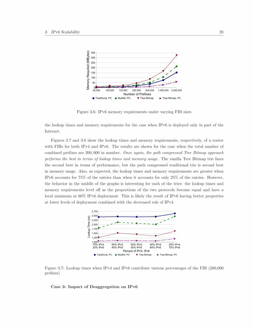
3. IPv6 Scalability 28
Figure 3.6: IPv6 memory requirements under varying FIB sizes
the lookup times and memory requirements for the case when IPv6 is deployed only in part of the
Internet.
Figures 3.7 and 3.8 show the lookup times and memory requirements, respectively, of a router
with FIBs for both IPv4 and IPv6. The results are shown for the case when the total number of
combined prefixes are 200, 000 in number. Once again, the path compressed Tree Bitmap approach
performs the best in terms of lookup times and memory usage. The vanilla Tree Bitmap trie fares
the second best in terms of performance, but the path compressed traditional trie is second best
in memory usage. Also, as expected, the lookup times and memory requirements are greater when
IPv6 accounts for 75% of the entries than when it accounts for only 25% of the entries. However,
the behavior in the middle of the graphs is interesting for each of the tries: the lookup times and
memory requirements level off as the proportions of the two protocols become equal and have a
local minimum at 60% IPv6 deployment. This is likely the result of IPv6 having better properties
at lower levels of deployment combined with the decreased role of IPv4.
Figure 3.7: Lookup times when IPv4 and IPv6 contribute various percentages of the FIB (200,000prefixes)
Case 3: Impact of Deaggregation on IPv6

3. IPv6 Scalability 29
Figure 3.8: Memory required when IPv4 and IPv6 contribute various percentages of the FIB (200,000prefixes)
We now consider the impact of other factors that cause the number of prefix entries in the routing
tables to increase. In particular, we consider the three prominent factors, namely load balancing,
multi-homing2, and failure to aggregate aggregatable prefixes. For exposition purposes, we label
this collection as deaggregation contributors.
We first develop a set of simple algorithms to simulate these deaggregation contributors. To
model load balancing, we split an existing prefix in half and announce a new, more specific route
for both halves. For multi-homing, we take an existing prefix, randomly select a sub-prefix that fits
inside the original prefix, and add both prefix entries. This models the case where a subset of an
address range must be stored separately, since it can arrive through multiple routes. For failure to
aggregate, we take a given prefix and create an identical prefix with just the last bit toggled, which
models a case where two prefixes could easily be aggregated, but are not.
We take two randomly generated routing tables from the previous section, one with 100,000
prefixes and one with 200,000 prefixes, and apply the set of algorithms to model the deaggregation
contributors. We model the cases where each algorithm is applied to a random 10%, 20%, and
30% of the entries in the table. We use a random sampling because it models the fact that prefix
assignment (and thus the prefixes included in route announcements) is determined independently
from the decision to employ traffic engineering (or failures to properly aggregate prefixes).
In Figure 3.9, we show the impact of adding entries due to the deaggregation contributors to the
lookup times on our 200, 000 entry table. (The results from the 100, 000 entry table were similar
and have been omitted for conciseness.) For each trie type, we observe increases in the lookup times
as the percentage of deaggregation increases. However, the lookup times for the vanilla Tree Bitmap
approach appears to be less affected by the increased deaggregation. Also, in each case, the tries
perform as well as before relative to each other. The memory requirements follow the same trend as
lookup times. We omit those results for brevity.
2While Shim6 [84] can be used to avoid routing table growth due to multi-homing in IPv6, it is difficult to predictShim6’s adoption. Accordingly, we choose to model multi-homing growth.
3. IPv6 Scalability 30
To be concise, we do not show how these results compare with the case when randomly picked
prefixes were added to the table, rather than picking entries specific to deaggregation contributors.
For most tries, tries with randomly picked entries fared better.
Figure 3.9: Impact of deaggregation on lookup times of IPv6 tables (200,000 prefixes)
3.6 Conclusion
It is generally accepted that routers will take longer to forward IPv6 packets, and that the routing
tables under IPv6 will get bigger. However, the extent of this degradation had not been explored.
In this chapter, we quantify the performance the routers must sacrifice under IPv6. Our results
also show that using path compression techniques can reduce this performance overhead by making
the lookups less dependant on the prefix length. We note that the Tree Bitmap approach used by
many modern routers [122], which yields the best performance and memory usage in IPv4 does not
fair so well with memory usage in IPv6. However, when we modified the algorithm to use path
compression, both its memory usage and lookup performance improved. This combined approach
has the potential to make the performance of IPv6 competitive with IPv4.
While we tried our best to project IPv6 deployment using the latest recommendations, actual
prefix allocations may be different. There is also a possibility that the number of entries in IPv6
routing table may be far fewer than what today’s IPv4 routing tables contain. This could happen
if some or all of the factors that inflate routing table entries today cease to exist. Short of knowing
what might happen, we used similar number of IPv4 and IPv6 entries for comparison purposes.
However, one cannot rule out the possibility that the performance overheads of longer IPv6 prefixes
may be offset by fewer entries.
This exploration of IPv6 has shown that IPv6 deployment can be accomplished in modern routers
with modest changes in the forwarding table data structures. Unfortunately, IPv6 deployment comes
at a premium: the memory requirements and lookup times are more demanding than IPv4. This
leaves room for improvement in other future Internet architectures.
4
Routing on Host Names
4.1 Introduction
Users of popular Internet applications specify service end points using human-friendly domain names.
The DNS resolves these domain names into IP addresses and the underlying communication subsys-
tem uses only the IP addresses to deliver data. This setup has worked well so far. However, today,
the unallocated IPv4 address space is scant. Although DNS scales due to its hierarchical nature of
local caching, the DNS infrastructure is vulnerable to many types of financial and security attacks,
including Denial-of-Service (DoS) and phishing.
This chapter takes a fresh approach to solving address exhaustion with the above concerns in
mind. We begin by questioning if it is important to have both IP addresses and host names to
identify end hosts. In fact, we conduct an exercise where we simply replace the IP-based addressing
and routing in the Internet with one where hosts are identified only by their names and the routing
subsystem forwards packets based on names. (Subsequently, we refer to the latter scheme as name-
based routing.) Using the widely-accepted domain names as host identifiers has the advantage that
the end users do not have to be concerned with aspects of Internet evolution. This is important to
make the transition to the new scheme practical. If adopted, name-based routing would have the
following impact:
Large Address Space: The domain names are extremely expandable in practice, allowing
37255 possible names. This figure stems from the fact that host names can be 255 characters long,
with 37 possible characters (case-insensitive letters, numbers, and hyphens). Compared to IPv6,
which allows 5.23×1028 IP addresses for each of the roughly 6.5 billion people on Earth, host names
allow 1.20 × 10390 addresses per person. This is roughly 362 orders of magnitude more addresses.
Thus, address space exhaustion concerns will be alleviated.
Reduced DNS Infrastructure: A translation from domain names to IP addresses would no
31
4. Routing on Host Names 32
longer be required, eliminating the need to have the DNS infrastructure1. Thus, all the DNS-related
security attacks will be eliminated.
Easier Network Provider Transitions: Currently, IP addresses serve both as identifiers as
well as locators, making it hard for organizations who lease network prefixes from their providers to
change providers. Since domain names are provider independent, this restriction will be eliminated
under name-based routing.
Many challenges need to be addressed before name-based routing can become a reality. First,
the IP header will have to be redesigned such that packets can contain domain names instead of
IP addresses. Second, the routing protocols will also have to be redesigned to exchange domain
names instead of IP prefixes. Third, scalability aspects of name-based routing tables and forwarding
speeds will have to be considered. Fourth, support for multi-homing, mobility, and advanced services,
such as multicasting and anycasting, will have to be provisioned. Finally, since a transition to the
new scheme cannot occur overnight, issues in backward compatability would have to be carefully
examined.
In this chapter, we take a first step at investigating the feasibility of name-based routing. Our
focus is primarily on comparing the performance of name-based packet forwarding with modern
IPv4 packet forwarding. Specifically, we evaluate the feasibility of name-based routing in terms of
the time required to create, look up, and update routing tables in the core of the Internet, and the
corresponding storage requirements.
Toward our goal, we use data from the DMOZ Open Directory Project [33], which contains user
submitted links, and the Route Views Project [120], which provides IP prefix information available
to the research community. Just like in Chapter 3, we implement various longest prefix algorithms
used by IPv4 routers in software. The analysis produced mixed results:
• The name-based routing results are slower than IPv4 in terms of lookup, creation, and update
times for each of the data structure we examined. In particular, compared to IPv4, the lookup
times are over 2.5 times slower for name-based routing while update times are about 2.7 times
slower.
• The biggest obstacle for name-based routing is the size of the routing table, which requires 1
to 2 orders of magnitude more storage than the corresponding IPv4 tables.
• To address the storage requirements, we explore the viability of caching the most popular
domains to reduce the number of entries in the routing table and explore a domain aggregation
approach to further reduce the number of entries. These techniques yield positive results, but
do not make the approach as compelling as we would like.
1Routing would still have to be secured. This issue would remained unchanged from today.

4. Routing on Host Names 33
4.2 Name-based Routing
To route on names instead of IPv4 addresses, inter-domain routers would have to maintain an
equivalent of a BGP FIB that would contain domain names instead of IP prefixes. We refer to this
table as the name-based routing table subsequently and routers employing this table as name-based
routers. For common cases, it is sufficient that this table for core Internet routers contain an entry for
1) each DNS second-level domain, e.g., university.edu and 2) each third-level domain for domain
names that contain countries as the Top Level Domains (TLDs), e.g., university.ac.in, along
with their corresponding outgoing interfaces. For simplicity of subsequent description, we refer to
all entries of the name-based routing table as domain names. Notice that finer granularity domains
names, e.g., cs.university.edu, do not need to be in name-based routing tables for core Internet
routers since they can be taken care of by the intra-domain routing. To forward packets toward
their destination, name-based routers will use the domain name of the destination and perform an
equivalent of today’s longest prefix match on the name-based routing table.
We compare the performance of IPv4 routers with name-based routers for traditional and path
compressed tries as described in Section 3.3. We leave out multi-bit tries, including the Tree Bitmap
approach, from our comparison because an even-handed comparison is hard to do when the optimal
stride sizes differ, which is likely to be the case because IPv4 prefixes and domain names have
fundamentally different characteristics.
4.2.1 Test Data
In order to model realistic name-based routing tables, we collected data from the DMOZ Open
Directory Project [33]. The project contains user submitted links and is the largest and most
comprehensive directory of the Web. Our input data, collected on October 28, 2006, has 9, 633, 835
unique URLs and 2, 711, 181 unique second and third-level domain names, as described earlier. We
compare this data with the July, 2006 results from the Internet Systems Consortium (ISC) Internet
Domain Survey [29]. The ISC data indicates there are 3, 105, 760 second-level domains. Thus, our
data includes approximately 73.38% of the second-level domains. This gives us confidence that we are
working with a representative sample of the Internet’s domains. For comparison with IPv4 routing
tables, we obtained a BGP FIB from one router in the Route Views Project [120] on November 15,
2006. The FIB contained 155, 854 entries, fewer than expected, possibly because the chosen vantage
point does not have all the announced IPv4 prefixes. As a result, the performance of IPv4 that we
measure is actually slightly better than it would be with complete records.

4. Routing on Host Names 34
4.2.2 Implementation of Longest Prefix Match Algorithms
We begin by parsing the links contained in the DMOZ data into DNS host names. We then aggre-
gate these host names into domain entries, which are used to populate both traditional and path
compressed tries. To do so, we use a simple heuristic, in which generic TLDs are grouped by their
second-level domains and most country code TLDs are grouped by their third level TLDs. Some
country codes have second level domains, in which case an individual host name is considered to be
a domain, introducing a small overestimate in the number of domains if there are multiple hosts in
the same domain in our data.
In each of the trie implementations, we hierarchically reverse the DNS names when storing
entries and when performing lookups. For example, www.university.edu is translated to edu.
university.www. This allows us to take advantage of the hierarchical structure of names to obtain
better branching.
The BGP FIB from Route Views is also parsed into AS-specific prefixes, which are then used as
input to the corresponding traditional and path compressed tries. Next, we describe the implemen-
tation of various tries.
Traditional Trie
The trie should support three basic functionalities: insertion, search, and update. In the case of a
name-based routing table, the unit of insertion, search, and update is a domain name while for a
IPv4 FIB, the unit is a prefix. The names are made up of 37 characters, 0-9, A-Z, and a ’-’ (the ’.’
is treated as a special value) while the prefixes can only be made of bits ’0’ and ’1’. The subsequent
discussion describes the routines for insertion, search, and update in a name-based routing table
where a character is consumed at a time. The traditional trie for IPv4 is populated similarly except
that a bit is consumed at a time and bit comparisons are used instead of character comparisons.
When storing an entry, the insertion routine recursively adds one character at a time from left
to right, starting at the root. At each hop, the routine finds the child node that matches the
first character in the input domain name. The insertion routine then removes the first character
of the input and recursively calls itself using the child node as the new insertion point. Upon
encountering a null child, the insertion routing creates a new node for the child, inserts it into its
parent node, removes the first character of input, and recursively calls itself. Once all the input has
been consumed, the next hop and output interface are stored at a terminal node off the last child.
The search routine also proceeds recursively, consuming a character of input at each hop. In
the name-based approach, the search routine checks for the existence of the next-hop and output
interface information at each “.” entry and records it if it exists. In the IPv4 approach, the search
routine checks for next-hop and output interface information at every hop. Upon encountering a
null child, the search process aborts and returns the next-hop and output interface it last recorded.

4. Routing on Host Names 35
An update is simply a deletion and insertion paired together. The deletion routine proceeds
similarly to the search routine. Upon encountering a null child, the deletion process aborts without
changing the structure, since no exact match is found in the structure. When the deletion has
consumed all of the input data, the deletion routine removes the next hop and output interface
information from the current node. The routine then completes.
When looking at a traditional trie analytically, we note that the worst case lookup time is O(L),
where L is the length of the input. This is because the trie traversal is based on this length,
consuming one character at each node. Similarly, the worst case for an update is O(L). The memory
requirements are O(L*N), where N is the number of entries than must be stored.
Path Compressed Trie
In a path compressed trie, each node can contain multiple characters or bits that it represents, in
addition to the characters/bits represented from its placement in the trie. Accordingly, the search
and deletion routines compare these additional characters/bits with their input. If they all match,
they are removed from the input and the process continues as before. If they do not match, processing
aborts as if a null child was encountered, since the input cannot exist in the trie.
The insertion routine is most affected by path compression. Upon encountering a null child when
inserting, the insertion creates a new node, stores the remainder of the input in it, and stores the
next hop and interface information. Additionally, if the insertion encounters a node, node A, which
is storing multiple characters, it attempts to match its entry with the stored characters/bits. Upon
finding characters/bits that do not match, the stored character/bit string is split. The matching
characters/bits are retained in node A. Two new nodes are then created: one for the remaining part
of the split string, node B, and one for the rest of the input in the entry being inserted, node C. All
of the children on node A are then moved to node B. Nodes B and C are then added as children on
node A. This process of building the trie takes advantage of compression whenever possible while
avoiding any special compression heuristics.
When looking at a path compressed trie analytically, we again note that the worst case lookup
and update times are O(L), where L is the length of the input. However, the memory requirements
are O(N), where N is the number of entries that must be stored. Note that the storage requirements
are independent of the input length, since the entire input can be compressed into a single node.
4.2.3 Comparison with IPv4
To compare the performance of name-based routing with IPv4 for both traditional and path com-
pressed tries, we examined for each approach: 1) the time required to create routing tables, 2) the
time required to lookup entries during packet forwarding, 3) the time required to update tables when

4. Routing on Host Names 36
entries get added or deleted, and 4) the storage requirements for routing tables. All the performance
trials were conducted on a machine with a Pentium IV 3.2 GHz processor with 2GBytes RAM. To
measure the timings, we use the RDTSC instruction, which can be used to measure the elapsed cycle
count, yielding nanosecond timing resolution.
Routing Table Creation Times
In Table 4.1, we show the average time required to create the name-based routing table which
had 2, 711, 181 entries and the IPv4 FIB, which had 155, 853 entries. We make comparisons both
for traditional and path compressed tries. Though the name-based routing tables take orders of
magnitude more time to load, these times are unlikely to impact forwarding speeds since the tables
typically need to be loaded only every few minutes.
Traditional Trie Path Compressed TrieName-based 24.383 19.231IPv4 0.612 0.384
Table 4.1: Average routing table creation times (in seconds)
The ISC Internet Domain Survey indicates that there has been a growth of roughly 50, 000
second-level domains every six months over the last 3 years. If this trend continues, there will be
roughly 4.25 million second-level domains in January 2018. This time-frame seems sufficiently large
to determine the scalability of our approach. We conclude that routing table creation times are a
non-issue for name-based routing.
Lookup Times
To determine lookup performance, we searched a randomly sampled 1% of the unique domains for
both traditional and path compressed tries. Table 4.2 shows the results for the name-based routing
table and the IPv4 FIB. Though lookups in the name-based tables cost more than IPv4 lookups for
both types of tries, they are of the same order.
Traditional Trie Path Compressed TrieAvg Min Max Avg Min Max
Name-based 6,842 2,070 54,140 6,460 2,290 51,238IPv4 2,618 1,070 10,455 2,525 910 5,283
Table 4.2: Lookup times (in nanoseconds)
Next, we looked at the distribution of lookup times obtained above. The Cumulative Distribution
Functions (CDFs) of the lookup times are shown in Figure 4.1. These CDFs indicate that the average
lookup times for name-based routing are worse than those for IPv4 because a larger percentage of
lookups for IPv4 finish in a small amount of time. In particular, 50% of the name-based lookups take
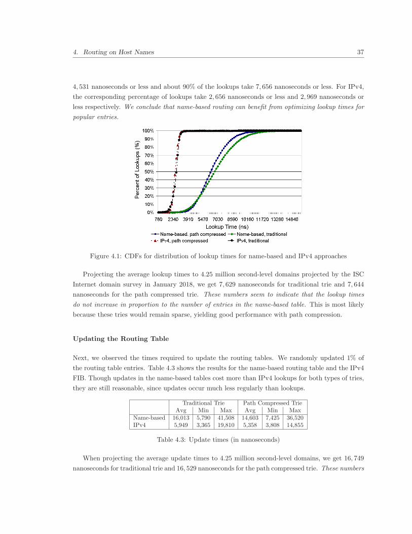
4. Routing on Host Names 37
4, 531 nanoseconds or less and about 90% of the lookups take 7, 656 nanoseconds or less. For IPv4,
the corresponding percentage of lookups take 2, 656 nanoseconds or less and 2, 969 nanoseconds or
less respectively. We conclude that name-based routing can benefit from optimizing lookup times for
popular entries.
Figure 4.1: CDFs for distribution of lookup times for name-based and IPv4 approaches
Projecting the average lookup times to 4.25 million second-level domains projected by the ISC
Internet domain survey in January 2018, we get 7, 629 nanoseconds for traditional trie and 7, 644
nanoseconds for the path compressed trie. These numbers seem to indicate that the lookup times
do not increase in proportion to the number of entries in the name-based table. This is most likely
because these tries would remain sparse, yielding good performance with path compression.
Updating the Routing Table
Next, we observed the times required to update the routing tables. We randomly updated 1% of
the routing table entries. Table 4.3 shows the results for the name-based routing table and the IPv4
FIB. Though updates in the name-based tables cost more than IPv4 lookups for both types of tries,
they are still reasonable, since updates occur much less regularly than lookups.
Traditional Trie Path Compressed TrieAvg Min Max Avg Min Max
Name-based 16,013 5,790 41,508 14,603 7,425 36,520IPv4 5,949 3,365 19,810 5,358 3,808 14,855
Table 4.3: Update times (in nanoseconds)
When projecting the average update times to 4.25 million second-level domains, we get 16, 749
nanoseconds for traditional trie and 16, 529 nanoseconds for the path compressed trie. These numbers

4. Routing on Host Names 38
again seem to indicate that the update times do not increase in proportion to the number of entries
in the name-based table.
Memory Requirements
To determine the amount of memory required to store the name-based routing table, we multiplied
the number of entries by the size of each entry. The first two columns of Table 4.4 show the storage
requirements of the name-based routing table and the IPv4 FIB. Clearly, the path compressed tries
fare much better for both name-based and IPv4 tables and the memory requirements of the name-
based routing table are very demanding. We conclude that name-based routing would require 2 to 3
orders of magnitude more memory than IPv4.
IPv4 Name-based Top 16% of Top 4% of(full trie) name-based name-based
entries entriesTraditional Trie 13.0 400.8 83.2 19.5Path Compressed Trie 8.9 163.7 29.1 7.2
Table 4.4: Comparison of storage requirements (in MBytes)
When projecting the storage requirements to 4.25 million second-level domains, we get 642.18
MBytes for traditional trie and 264.11 MBytes for the path compressed trie.
4.3 Optimizing Memory Requirements for Name-based Rout-
ing Tables
The greatest difficulty for the name-based approach seems to be the storage requirements, which
are two orders of magnitude greater than IPv4 for both traditional and path compressed tries. As
a result, the memory required to store the entire name-based trie may be too much to fit into the
faster SRAM on routers. Previous work indicates that a significant portion of traffic is destined to a
small subset of destinations [39, 99, 116]. Guided by this observation, we now explore the trade-offs
of storing high-usage domains in fast memory and using the slower memory, such as DRAM, for
cache misses.
We estimate domain popularity using the number of times a domain appears in the unique URLs
contained in the DMOZ data. For each link, we determine the domain associated with it. We
then add the number of times each domain appears in the list and take this as an indication of
domain popularity. As shown in Figure 4.2, the DMOZ data revealed a heavy tail distribution. In
particular, the top 4% most popular domains account for 35.75% of URLs and the top 16% most
popular domains account for 50.06% of URLs.

4. Routing on Host Names 39
Figure 4.2: Cumulative distribution function for domain popularity
To evaluate the performance of caching tries corresponding to popular domains, we modify our
code to include a smaller, cached trie as well. Entries are either inserted into the cached trie or the
regular trie, depending on its popularity. Lookups and updates are first conducted on the cached
trie and proceed to the regular trie only if no match is found in the cached trie.
We perform these tests for both path-compressed and traditional tries. We experimented with
two cases: when the smaller trie contains 16% of the most popular unique domains and when it
contains 4% of the most popular unique domains. Table 4.4 shows the storage requirements for the
caches. The cached tries containing 4% entries come very close to the corresponding traditional
IPv4 tries. For the path compressed trie, the cached trie with 4% entries is well within the bounds
of the SRAM in modern routers.
As shown in Figure 4.3, caching 4% of the entries reduces the lookup times for more than 60% of
the lookups. Caching 16% of the entries does not yield as great results, indicating costs of traversing
a larger cache trie offset the higher cache hit percentage. These caching benefits come at the cost
of increased lookup times for the less popular domains, since they must look through two tries. We
note this analysis is all performed in software and DRAM, which does not show the advantage of
caching in higher speed memory. We conclude that caching can yield performance advantages for
popular entries for the majority of lookups.
4.4 Other Issues in Adopting Name-Based Routing
There are several other open issues with switching to name-based routing. A redesign of the routing
protocols and IP header is required to enable a transition to the proposed name-based scheme. This
could be accomplished by adding a name-layer on top of the IPv4 header. The issue of encoding
domain names in the network layer would also require careful consideration. Clearly, host names
are longer than IPv4 addresses and encoding them in each packet’s header will cause the packet

4. Routing on Host Names 40
Figure 4.3: Comparison of CDFs for lookups in name-based path-compressed tries with and withoutcaching
header size to increase. However, the extra overhead may not be worse than IPv6. This can be seen
in Figure 4.4, where we plot a CDF of the character length of the full host names from our DMOZ
data set. We note that 99.59% of host names are 36 characters or shorter. Further, 67.62% are 21
characters are shorter. Since each domain name character can be encoded in 6 bits, a 21 character
name would require only 15.75 bytes whereas an IPv6 address would require 16 bytes. If an efficient
variable-length encoding were used, it is possible that the name-based headers would actually be
shorter than IPv6 for the majority of traffic.
Figure 4.4: CDF of the percentage of hosts with given number of characters
Partial deployment scenarios necessitate using legacy infrastructure between deploying sites.
Deploying routers can use IPv4 tunneling to traverse legacy routing infrastructure. However, the
last deploying router on the path cannot use tunneling, so both edge networks must be compliant
for the approach to succeed.

4. Routing on Host Names 41
4.5 Conclusion
In this chapter, we sought to determine the feasibility of routing on names. We find that name-based
routing under-performs IPv4 routing. The difference is most evident in forwarding performance, in
which name-based routing requires over 2.5 as long as IPv4 to forward packets, and is most acute
in memory requirements, where name-based routing costs two orders of magnitude more memory.
The analysis in this chapter assumes that all hosts in a domain can be represented as one entry
in the routing tables. This implies that the hosts in a domain are near each other in the network
topology and have similar routing characteristics. Without aggregation, we would need a separate
routing entry for each of the hosts in the domain, which would further increase the router memory
requirements and reduce forwarding performance. In Chapter 5, we investigate this issue and find
that this assumption is often valid, but cases where separate entries are needed may cause growth
and worsen the performance of name-based routing.
Being able to aggregate all hosts belonging to the domain into a single routing table entry is not
sufficient to scale name-based routing since there are estimated to be 153 millions domains, each of
which would require its own entry. In comparison, we have only around 300 thousand routing table
entries today. Even though our study shows that caching the most commonly visited domain names
will be effective at the edge routers, more is needed to scale name-based routing. In Chapter 6,
we examine an approach that investigates where domains that may be topologically close can be
aggregated under a single identifier. Depending on the co-location of domains, this could reduce the
number of routing table entries in our scheme significantly.

5
Examining Topological Proximity of Hosts
Within a Domain
5.1 Introduction
One of the most significant design aspects of the IPv4 and IPv6 addressing schemes is the ability
to aggregate IP addresses into prefixes. Machines that are close in network topology often share a
prefix. Prefixes help scale routing to billions of machines by compacting the size of the routing tables;
smaller routing tables lend themselves to faster lookups and fewer routing messages to maintain those
tables.
The DNS hierarchy was not designed with similar goals. While hosts associated in a domain
typically co-locate topologically, it is not required. In Chapter 4, we assumed that hosts within a
domain could be represented in host name-based routing tables by a single entry for their domain.
This would allow routers under name-based routing to store entries at the domain granularity, which
is necessary for faster lookups and for reducing storage requirements. Given the importance of host
aggregation in our work, it is important to ascertain that hosts belonging to a domain can indeed
be represented through a single entry for their domain.
In this Chapter, we examine domains in the Internet to determine whether hosts from a domain
are near each other in the underlying network topology. A typical unit of administration in DNS
is a second-level domain name, such as example.com. A zone file corresponding to the zone stores
information about the hosts, services, and sub-domains contained in that zone. While typical DNS
queries inquire about a single host or service, some use-cases require complete information contained
in a DNS zone. An instance of this occurs when DNS servers for a domain need to synchronize to
obtain a consistent view of the zone. The DNS provides a special query for that, called the zone
transfer query. In this chapter, we perform DNS zone transfer query to capture detailed information
about DNS zones in the Internet. During a three month period, we swept 74 million zones, roughly
42

5. Examining Topological Proximity of Hosts Within a Domain 43
60% of the Internet, using zone transfers. Since zone transfers may be considered a security risk, zone
transfers may only provide us with information biased towards domains with lax security practices.
To avoid this bias, we additionally walked the zones of the second-level domains known to deploy
DNSSEC [10] to obtain additional zone data. Given the security role of DNSSEC, these domains
may be biased towards security conscious zones. While slow, this process allows us to obtain the
same information as a zone transfer. This data allows us to characterize the diversity of zones in the
Internet in terms of number of hosts, the domains, ASes and BGP prefixes to which they belong.
From these measurements, we find:
• DNS domains (or zones) vary vastly in size, with the largest zone containing over two million
hosts while a significant fraction contain just a handful.
• About 59.10% of zones were confined to a single AS, with each host name in the zone having
an IP address belonging to that AS. Another 38.03% of zones spanned only two ASes. An
additional 2.32% of zones span three domains while 0.35% of zones span four or more ASes.
5.2 DNS Zone Breadth and Depth
5.3 Background
The behavior of the DNS is specified in a series of IETF RFC documents, dating back to the 1980s.
While there are many DNS-related RFCs, the key RFCs describing the basics are RFC 1034 and
1035 [78, 79].
The DNS is organized as a tree, with branches at each level separated by a “.”. The entire DNS
space is divided into various zones. Each zone consists of a connected portion of this tree under
the same administrative control. A typical unit of administration in DNS is a second-level domain
name, such as example.com. A zone file corresponding to this second-level domain name stores
information about the hosts, services, and sub-domains contained in that zone.
The data within each zone is stored in the form of resource records which consists of four basic
parts: a name, a class, a type, and data. All DNS records relating to the Internet are in IN class.
59 different types of records exist for storing various types of data. A zone is defined by two types
of records. The first, SOA (Start of Authority), indicates the start of a DNS zone. Each zone should
have a SOA record. The contents of the SOA record are the email of an administrator, the domain
name of the primary name server, and various timers. The second, one or more NS (Name Server)
records, also should exist in each zone. These records indicate the set of name servers for the zone
and can also indicate the delegation of sub-zones.
5. Examining Topological Proximity of Hosts Within a Domain 44
Every DNS zone must have at least one name server which serves the DNS records within that
zone. Normally, there is more than one name server for a zone, with one being designated as the
primary name server and any others being designated as secondary name servers. A zone transfer,
initiated by an AXFR query is typically used to transfer the zone data from the primary name server
for a zone to the secondary name servers. The primary name server typically loads its data from a
flat file known as a zone file.
5.4 Data Collection Methodology and Issues
We use two data sets in this paper. The first, zone transfer, was obtained by attempting to transfer
the zones listed under .com and .net. There were 65,101,733 second-level domains under .com and
9,224,482 under .net. Combined, these 74,326,215 domains represented about 58% of the 128 million
zones registered at the time [123]. For each zone, we had the list of name servers. We looked up the
IP addresses corresponding to each of these name servers in order to be able to contact them. We
used our own custom software, written using the Net::DNS Perl library [69], to zone transfer each of
these DNS zones in random order. This process took three months, in part because zone transfers
are connection-oriented, unlike regular DNS queries, which are connectionless. We attempted a
zone transfer from each name server for a zone until we either successfully transferred the zone, or
the zone transfer failed for all its name servers. Additionally, if two zone transfers from the same
IP address failed, or upon request from the DNS server’s administrator, we discontinued making
further attempts to transfer any zone from that IP address. Upon connection establishment failure,
we retried once. In order to expedite the process, we used five machines, each with one hundred
processes issuing zone transfer requests. We succeeded in transferring zones for 4,947,993 (6.6%),
indicating that many DNS servers willingly distribute their information to outsiders. While our data
set was confined to the .com and .net top level domains (TLDs), it still contained geographically
distributed sites.
Our second data set, dnssec, is composed of sites that deploy DNSSEC [10] and may be consid-
ered to be more security conscious. DNSSEC, which is a set of extensions to the DNS, adds security
to the DNS, including origin authentication and integrity to DNS data, and authenticated denial of
existence. We obtained the dnssec data set through walking DNSSEC records. This process is slow
but allows retrieval of all the records in a zone, much like a zone transfer. This data set is limited
by the low deployment of DNSSEC. To build this data set, we began with a list of 862 zones with
DNSSEC in production usage from the SecSpider DNSSEC Monitoring Project [87]. We limited
this to the second level zones within the .com and .net TLDs to allow a fair comparison with the
zones we transferred data from in the same TLDs. This yielded a total of 124 zones. Surprisingly,
we also found 161 zones deploying DNSSEC in our zone transfer data. Since 96 of the zones listed
under SecSpider already existed in our zone transfer data, we only had to obtain data from the
rest of the 28 zones that did not allowed us a zone transfer. (We excluded those 96 zones from the

5. Examining Topological Proximity of Hosts Within a Domain 45
first data set.) To obtain data from the 28 new zones in the SecSpider data, we used the DNSSEC
Walker tool [62]. This tool relies on the presence of NSEC (NextSECure) or NXT (NeXT) records
which should be present in zones deploying DNSSEC. These records provide a way to discover all
of the records from within a zone without using zone transfer. Of the 28 zones we attempted to
walk, 4 were only partially walkable due to missing some NSEC or NXT records. The remaining 24
were completely walkable allowing us to get the same information as we would though zone transfer
without actually using the zone transfer query. Our final dnssec data set consists of 189 total zones.
5.4.1 Non-technical Data Collection Issues
While zone transfers yield valuable information for research purposes, the technique raises practical,
ethical, and legal questions. We encountered various reactions to our data collection efforts from
the zone administrators. Many of the early requests we received were concerns that a machine had
been compromised or that we were otherwise attacking their systems. As the project progressed, we
decided to alter the PTR records (used to map IP addresses to domain names) for each of the scanning
machines to indicate that they were involved in DNS research and encouraging the administrators
to perform a query for the TXT (TeXT) record on the host name for more details. The TXT record is
a free-form record, allowing one to put information in any format. This led the them to a web page
explaining the project in detail. This page attracted approximately 300 hits while the experiment
was on-going. Over half of the administrators that contacted us were supportive of the work, with a
few being being quite enthusiastic. A small number of them requested to have their servers exempted
from the scanning, which we promptly honored. One administrator seemed surprised that we would
perform such queries without prior permission. Further, even after hearing about the research, one
administrator was livid and stated that our entire prefix had been blocked from his network, with
the apparent exception of his mail server.
The issue of zone transfers has since reached the legal system. In a civil court ruling which
occurred after our data collection, a North Dakota civil court decision declared unauthorized zone
transfers in that state illegal [110]. While the circumstances in that case were unique, it is clear that
such queries can be viewed as controversial. This further raises the bar on collecting and analyzing
the type of data we present in this chapter.
5.5 Overview of Collected Data
We sanitized the data by removing repeated records, records with empty name field, records that
exhibited failed attempts at commenting, and records that were not supposed to have been trans-
ferred (such as those belonging to a sub-zone). We now present a combined overview of the collected
data.
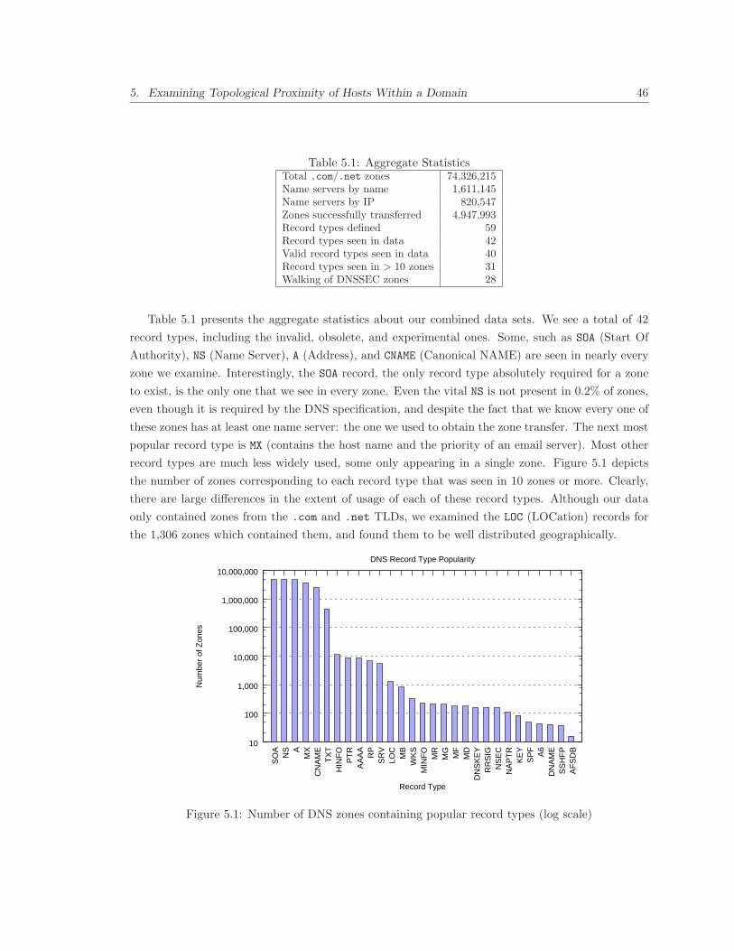
5. Examining Topological Proximity of Hosts Within a Domain 46
Table 5.1: Aggregate StatisticsTotal .com/.net zones 74,326,215Name servers by name 1,611,145Name servers by IP 820,547Zones successfully transferred 4,947,993Record types defined 59Record types seen in data 42Valid record types seen in data 40Record types seen in > 10 zones 31Walking of DNSSEC zones 28
Table 5.1 presents the aggregate statistics about our combined data sets. We see a total of 42
record types, including the invalid, obsolete, and experimental ones. Some, such as SOA (Start Of
Authority), NS (Name Server), A (Address), and CNAME (Canonical NAME) are seen in nearly every
zone we examine. Interestingly, the SOA record, the only record type absolutely required for a zone
to exist, is the only one that we see in every zone. Even the vital NS is not present in 0.2% of zones,
even though it is required by the DNS specification, and despite the fact that we know every one of
these zones has at least one name server: the one we used to obtain the zone transfer. The next most
popular record type is MX (contains the host name and the priority of an email server). Most other
record types are much less widely used, some only appearing in a single zone. Figure 5.1 depicts
the number of zones corresponding to each record type that was seen in 10 zones or more. Clearly,
there are large differences in the extent of usage of each of these record types. Although our data
only contained zones from the .com and .net TLDs, we examined the LOC (LOCation) records for
the 1,306 zones which contained them, and found them to be well distributed geographically.
10
100
1,000
10,000
100,000
1,000,000
10,000,000A
FS
DB
SS
HF
PD
NA
MEA6
SP
FK
EY
NA
PT
RN
SE
CR
RS
IGD
NS
KE
YM
DM
FM
GM
RM
INF
OW
KS
MB
LOC
SR
VR
PA
AA
AP
TR
HIN
FO
TX
TC
NA
ME
MXA
NS
SO
A
Num
ber
of Z
ones
Record Type
DNS Record Type Popularity
Figure 5.1: Number of DNS zones containing popular record types (log scale)

5. Examining Topological Proximity of Hosts Within a Domain 47
1
10
100
1000
10000
100000
1e+06
1e+07
1 10 100 1000 10000 100000 1e+06 1e+07
Num
ber
of Z
ones
Number of A Records
A Records per Zone
Figure 5.2: Number of A records per zone in the combined data set (log-log scale)
5.6 Zone Size and Breadth
We now examine the size and breadth, the degree to which a zone spans across ASes and BGP
prefixes, of DNS zones contained across our two data sets.
5.6.1 Zone Sizes
One approach to looking at zone sizes is to look at the total number of records contained in various
zones. However, this approach is dependent on what record types a zone chooses to use. Some
records, such as CNAME, do not add any new hosts but provide extra information about an existing
record. Thus, we count the A records in order to estimate the size of a zone. Since all hosts must
have an A record, the number of A records in a zone should roughly correspond to the number of
hosts in the zone intended to be accessible though DNS. We ignore the AAAA (IPv6 address) records
in counting hosts since very few zones use IPv6 and even when they do, they usually have IPv4
records for the same hosts.
Figure 5.2 shows the number of A records per zone. As seen in the figure, a majority of zones
are small, containing only one A record. Some have more, but it is surprising how many more.
The largest has 2,073,715 A records. There are additionally 14 others with over 100,000 A records,
although no others with over 1,000,000. The largest zone we see has many A records in part because
they have an A record for each address in the 10.32.0.0-10.63.255.255 private IP address space in
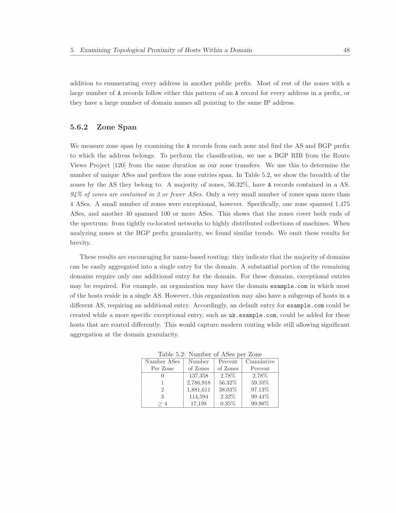
5. Examining Topological Proximity of Hosts Within a Domain 48
addition to enumerating every address in another public prefix. Most of rest of the zones with a
large number of A records follow either this pattern of an A record for every address in a prefix, or
they have a large number of domain names all pointing to the same IP address.
5.6.2 Zone Span
We measure zone span by examining the A records from each zone and find the AS and BGP prefix
to which the address belongs. To perform the classification, we use a BGP RIB from the Route
Views Project [120] from the same duration as our zone transfers. We use this to determine the
number of unique ASes and prefixes the zone entries span. In Table 5.2, we show the breadth of the
zones by the AS they belong to. A majority of zones, 56.32%, have A records contained in a AS.
94% of zones are contained in 2 or fewer ASes. Only a very small number of zones span more than
4 ASes. A small number of zones were exceptional, however. Specifically, one zone spanned 1,475
ASes, and another 40 spanned 100 or more ASes. This shows that the zones cover both ends of
the spectrum: from tightly co-located networks to highly distributed collections of machines. When
analyzing zones at the BGP prefix granularity, we found similar trends. We omit these results for
brevity.
These results are encouraging for name-based routing: they indicate that the majority of domains
can be easily aggregated into a single entry for the domain. A substantial portion of the remaining
domains require only one additional entry for the domain. For these domains, exceptional entries
may be required. For example, an organization may have the domain example.com in which most
of the hosts reside in a single AS. However, this organization may also have a subgroup of hosts in a
different AS, requiring an additional entry. Accordingly, an default entry for example.com could be
created while a more specific exceptional entry, such as uk.example.com, could be added for these
hosts that are routed differently. This would capture modern routing while still allowing significant
aggregation at the domain granularity.
Table 5.2: Number of ASes per ZoneNumber ASes Number Percent Cumulative
Per Zone of Zones of Zones Percent0 137,358 2.78% 2.78%1 2,786,918 56.32% 59.10%2 1,881,611 38.03% 97.13%3 114,594 2.32% 99.44%
≥ 4 17,198 0.35% 99.98%

5. Examining Topological Proximity of Hosts Within a Domain 49
5.7 Conclusion
In this Chapter, we examined domains in the Internet. We found that many DNS domains had only
a few hosts, but a few were quite large with millions of hosts. When we examined whether DNS
domains spanned multiple ASes, we found that the majority were contained in a single AS and over
97% of domains were contained in two or fewer ASes. However, some zones broke the trend: one
zone spanned 1,475 different ASes.
This work directly impacts the viability of name-based routing. In most cases, it is possible to
aggregate DNS hosts into a single domain label without affecting the network topology, as suggested
in Chapter 4. This is essential to minimizing the size of the routing table and the lookup times
required to forward packets. However, in many cases, the scheme must also allow multiple DNS
aggregate labels per domain. While two DNS aggregate labels will suffice for almost all of the
Internet, some exceptional cases exist and must be supported in such a scheme. Further, some
aggregation may be possible across multiple domains. We investigate this further in Chapter 6.

6
Investigating Domain Aggregates to
Reduce Routing Table Size
6.1 Introduction
In Chapter 4, we propose an architecture where packets are forwarded on host names. In Chapter 5,
we confirmed that we can often aggregate hosts in a domain into a single domain-wide entry. This
approach increases routing scalability by allowing us to store fewer entries at routers. However, even
with this aggregation, there are 153 million domains at the time of writing while there are currently
only about 300 thousand IP prefixes. Clearly, as we conclude in Chapter 4, it will be infeasible in
the foreseeable future to forward packets under our architecture in the required tens of nanoseconds
packet forwarding speeds.
We investigate an approach to reduce the number of routing table entries. The approach examines
if multiple domains can be aggregated together. If several domains are co-located in the same
network, we could group these domains and announce these aggregates. If routers were to forward
these packets using these domain aggregates, the resulting forwarding tables could be smaller. This
would reduce the memory requirements for storing the routing tables and hence lead to better packet
forwarding performance. Recall that this was a significant obstacle in the host name-based routing
proposed in Chapter 4.
To accomplish our goal, we resolve host names from a significant fraction of the Internet just as
a client would in order to retrieve the host’s IP address. For our measurements, we focus on Web
servers, as they are often a motivator for acquiring a DNS domain and should be representative of
host names. Using the IP addresses contained in these resolutions, we determine if hosts belonging
to many domains are co-located in the network topology. If so, they can be represented by an
aggregate routing table entry, which will reduce the size of routing tables depending on the extent of
50
6. Investigating Domain Aggregates to Reduce Routing Table Size 51
co-location. In performing these measurements, we examine about 59% of the domains to determine
Web server names and addresses throughout the Internet. From these measurements, we find:
• As much as 60% of the Web servers are co-hosted with 10, 000 or more Web servers for other
domains. This indicates that it many domains may be aggregated at the IP granularity which
may yield fewer entries in name-based routing tables, enhancing the scalability of the approach.
• More than 95% of Web servers share their AS with 1000 or more other Web servers. Such
co-location is consistent with the intuition that smaller organizations may use Web hosting
companies which results in co-located Web sites.
• In performing these measurements, we found some additional insights. IP-based blacklisting
can hurt co-located domains, so domain-based blacklisting is required to minimize collateral
blocking.
6.2 Data Collection and Methodology
We use two primary data sets for this analysis. The first is from the DMOZ Open Directory
Project [33]. The project contains user submitted links and is the largest and most comprehensive
directory of Web URLs. A typical URL from DMOZ data contains several pieces of information.
For example, in the URL www.example.com/content.html, www.example.com is the Web server
name, which belongs to domain example.com and top level domain (TLD) .com. The actual file
being accessed is content.html.
The DMOZ data set covers over 234 different TLDs, making it an international data set covering
over 90% of the TLDs. We use a snapshot of DMOZ data from October 28th, 2006. From the DMOZ
URLs, we extract the names of unique Web servers offering content. We conduct DNS lookups on
each of these names to get their corresponding IP addresses, which are returned in the form of
type A resource records. The unique IP addresses from these DNS responses are used to infer the
relationship between Web servers and IP addresses. If a Web server name resolves to multiple IP
addresses, we select the lowest IP address returned. This helps avoid counting a cluster of Web
hosting servers multiple times.
The second data set contains DNS zone files [124] from the .net and .com TLDs. These zone
files list each of the domains in the respective TLD zones. The data presented here is from the zone
files we obtained on March 7th, 2007. To obtain the Web server name for each domain listed in the
zone file, we simply prefix each domain name with “www.”, since most Web servers are named in
this fashion. We then resolve each Web server name into an IP address using DNS queries, as we
do for the DMOZ data set.

6. Investigating Domain Aggregates to Reduce Routing Table Size 52
The DMOZ data set contains URLs corresponding to .com and .net TLDs, in addition to other
TLDs from around the world. In fact, about half of the DMOZ Web servers correspond to these
TLDs. Since these domains are exhaustively listed in the zone files, we eliminate them from the
DMOZ data. Henceforth, when we refer to the DMOZ data set, we mean its curated version which
excludes entries from the .com and .net TLDs. Together, these two data sets represent a sizeable
chunk of the Web today, since they contain 75.7 million of the 128 million domains registered
worldwide in June 2007 [123].
Table 6.1 shows the number of unique URLs, Web servers, and IP addresses contained in both the
data sets. Two things are noteworthy about this table. First, the .com and .net TLDs contained in
the zone files by themselves contain an order of magnitude more domain names than the rest of the
TLDs represented in the DMOZ data. Second, for each data set, the number of unique IP addresses
belonging to the Web servers is also an order of magnitude less than the number of Web servers
themselves. This is an initial indication that many Web servers are co-located. We explore this in
detail in Section 6.3.
DMOZ Data Zone Files(curated)
Number of URLs 4,667,792 -Unique Web Servers 1,487,481 74,326,215A Records Received 1,396,998 71,855,113Unique IPs 487,797 3,641,329TLDs Represented 232 2Unique ASes Represented 12,374 18,356
Table 6.1: Overview of DMOZ and zone files data
6.3 Web Server Co-location
We begin by investigating where the Web servers are located in terms of the IP addresses of machines
that these servers are hosted on. Notice that our analysis focuses on the actual Web servers and
does not include the servers belonging to CDNs, which many well-provisioned Web sites tend to use.
Figure 6.1(a) shows the number of Web servers per unique machine as a percentage of IP addresses
and Web servers for the DMOZ data set. Figure 6.1(b) shows similar information for the zone
files. Note that the X-axis is a log scale in both figures. From these figures, we draw several
key observations. First, they show that most machines host only a handful of Web servers. As
many as 69 − 71% of the IPs in both our data sets host just one Web server. While this may
lead one to conclude that there is a one-to-one correspondence between the Web servers and the
IP addresses, the story changes completely when one looks at the Web servers per IP address as a
percentage of Web servers. We find that only between 4 − 24% of Web servers in our two data sets
are hosted on a machine by themselves. The rest are co-hosted on the same machines with other Web

6. Investigating Domain Aggregates to Reduce Routing Table Size 53
20%
30%
40%
50%
60%
70%
80%
90%
100%
1 10 100 1000 10000
Per
cent
age
of IP
s/W
eb S
erve
rs
Web Servers per IP
IPs
Web Servers
(a) DMOZ Data set
0%
10%
20%
30%
40%
50%
60%
70%
80%
90%
100%
1 10 100 1000 10000 100000 1e+06 1e+07
Per
cent
age
of IP
s/W
eb S
erve
rs
Web Servers per IP
IPs
Web Servers
(b) Zone files
Figure 6.1: Cumulative distribution functions showing Web servers per IP address as a percentageof IP addresses and Web servers
servers. This implies that while a rather small percentage of well-provisioned Web servers employ
dedicated machines to host, the rest are co-hosted. This co-hosting implies that domains may share
infrastructure and could be summarized in a single entry in name-based routing tables. This affects
the scalability and performance of name-based routing.
Figures 6.1(a) and 6.1(b) also illustrate the differences between the DMOZ and zone files data
sets. First, the X-axis differs in that the zone files have Web servers that have orders of magnitude
more Web servers per IP address than those in DMOZ data. Since zone files exhaustively represent
the .com and .net TLDs, this implies that more Web servers in these TLDs are co-located. Second,
Figure 6.1(a) also shows that a much larger percentage of Web servers represented in the DMOZ
data are hosted either by themselves or are co-hosted with a small number of other Web servers.
Specifically, as much as 84% of the DMOZ Web servers are co-hosted with 100 or fewer other Web
servers while only 15% of the Web servers contained in the zone files are co-hosted with 100 or fewer
other Web servers. Further, under 6% of the DMOZ Web servers are co-hosted with 1, 000 or more
Web servers while as much as 65% of the Web servers contained in the zone files are co-hosted with
1, 000 or more Web servers. In fact, as much as 60% of the Web servers in the zone files are co-hosted
with 10, 000 or more Web servers! There could be two explanations for the differences in the two
data sets. First, TLDs outside of .com and .net may be co-located less often. Alternatively, the
DMOZ data may be dominated by well-provisioned Web servers.
6.3.1 Co-location in Terms of ASes
We now analyze Web server co-location as seen from the perspective of ASes the Web servers are
located in.
Additional Data Used: In order to infer co-location in terms of ASes advertised by these ASes,

6. Investigating Domain Aggregates to Reduce Routing Table Size 54
we gather a third data set: a BGP routing table from a router in the Route Views Project [120].
The table contains 237, 819 prefixes advertised by BGP routers in the Internet, along with the ASes
that originate these prefixes. We use an April 22, 2007 snapshot of the routing table, which is from
around the same time as when we performed the DNS resolutions on Web server names. For each
IP address, we perform a longest prefix match on this table to obtain the AS for the IP address.
0%
10%
20%
30%
40%
50%
60%
70%
80%
90%
100%
1 10 100 1000 10000 100000 1e+06
Per
cent
age
of A
Ses
/Web
Ser
vers
Web Servers per AS
ASes
Web Servers
(a) DMOZ Data set
0%
20%
40%
60%
80%
100%
1 10 100 1000 10000 100000 1e+06 1e+07
Per
cent
age
of A
Ses
/Web
Ser
vers
Web Servers per AS
ASes
Web Servers
(b) Zone files
Figure 6.2: Cumulative distribution functions showing Web servers per AS as a percentage of ASesand Web servers
Analysis: Figures 6.2(a) and 6.2(b) show the co-location in terms of ASes for the DMOZ data
and zone files respectively. These figures show that 19.27% of ASes in the DMOZ data set and
10.78% in the zone file data have only one Web server. However, only a very small percentage of
Web servers are hosted in an AS by themselves. The case is more pronounced for the zone files,
where even fewer Web servers exist by themselves. Specifically, more than 60% of the DMOZ Web
servers share their ASes with 1, 000 or more other Web servers. Correspondingly, more than 95% of
the Web servers in the zone files share their AS with 1, 000 or more other servers. These findings
indicate that the Web is more highly co-located when seen from the perspective of ASes containing
the Web servers.
6.4 DNS Server Co-location
After finding extensive co-location in Web servers, we were curious to see whether such co-location
was present in the DNS infrastructure used. Since authoritative DNS servers are required for clients
to reach their targeted Web server, the co-location of DNS servers has important implications on
the availability of Web servers. Here, we look at the extent to which authoritative DNS servers are
co-located, both at the IP address and AS granularity.

6. Investigating Domain Aggregates to Reduce Routing Table Size 55
6.4.1 Additional Data Used
To infer DNS server co-location, we needed to collect information about authoritative DNS servers
for the Web servers contained in our two primary data sets. Fortunately, the zone files already
contain information on the authoritative DNS servers for each domain listed. However, the process
was not so straight-forward for the DMOZ data. We had to conduct DNS lookups for NS records to
determine the list of authoritative DNS servers for each of the Web servers contained in the DMOZ
data. Further, we resolved the output of each NS lookup, which is generally a host name, into IP
address using the DNS A record lookups.
For both data sets, Table 6.2 illustrates the unique authoritative DNS servers by name and also
the distinct IP addresses these correspond to. It also shows the distinct DNS servers by name and
IP address for the combined data set. We combine the data sets before further analyzing them
because 74.9% of the DNS servers from the DMOZ data are common to the DNS servers for the
zone files. This indicates that Web servers from a variety of different TLDs are hosted on the same
authoritative DNS servers.
DMOZ Data Zone Files CombinedDNS Servers 278,169 1,611,145 1,710,847Unique IPs 223,992 820,547 875,122
Table 6.2: Authoritative DNS servers for DMOZ data and zone files
For DNS server co-location analysis based on ASes, we convert DNS server IP addresses to ASes
by using a BGP routing table described in Section 6.3.1.
6.4.2 Analysis
As shown in Figure 6.3(a), most DNS servers are authoritative for only a small number of domains
(and hence for the Web servers contained in those domains). Note the log scale on the X-axis. In
particular, 30% of them are authoritative for only one domain. The median number of domains a
DNS server is authoritative for is 4. However, there are several DNS servers that are authoritative
for a very large number of domains. In particular, there are 11 DNS servers in our list which are
each authoritative for over 1, 000, 000 domains, with the highest being authoritative for 3, 757, 103
domains! This raises questions about the availability of Web servers in the event of targeted DoS
attacks. We show the results for AS-level analysis in Figure 6.3(b). The key results for the AS
granularity are similar, with 63.61% of the ASes containing DNS servers that are authoritative for
100 or fewer domains. Also, we find 19 ASes that have authoritative DNS servers for over 1, 000, 000
domains, with the highest one hosting 9, 544, 010 domains.
While co-location threatens availability in the case of a DoS attack or system failure, another
factor may balance it. This factor is the redundancy of authoritative DNS servers, as recommended
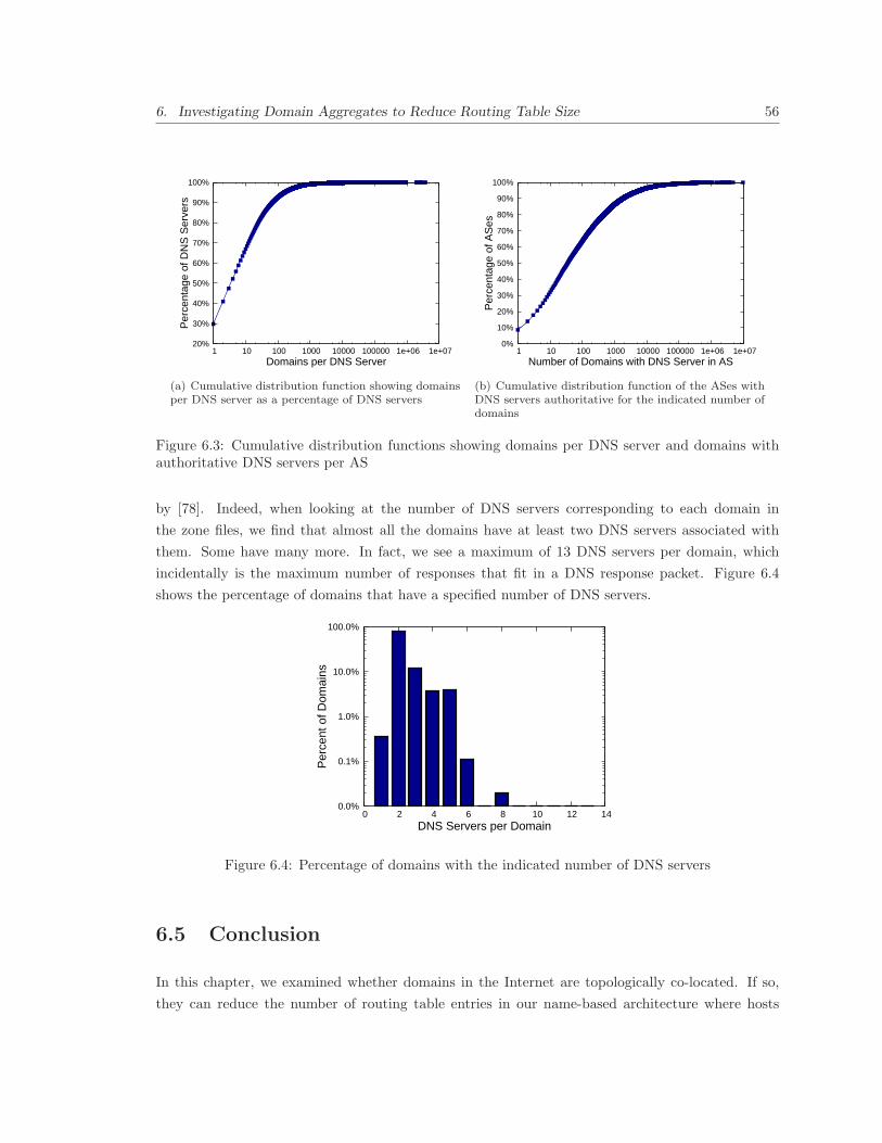
6. Investigating Domain Aggregates to Reduce Routing Table Size 56
20%
30%
40%
50%
60%
70%
80%
90%
100%
1 10 100 1000 10000 100000 1e+06 1e+07
Per
cent
age
of D
NS
Ser
vers
Domains per DNS Server
(a) Cumulative distribution function showing domainsper DNS server as a percentage of DNS servers
0%
10%
20%
30%
40%
50%
60%
70%
80%
90%
100%
1 10 100 1000 10000 100000 1e+06 1e+07
Per
cent
age
of A
Ses
Number of Domains with DNS Server in AS
(b) Cumulative distribution function of the ASes withDNS servers authoritative for the indicated number ofdomains
Figure 6.3: Cumulative distribution functions showing domains per DNS server and domains withauthoritative DNS servers per AS
by [78]. Indeed, when looking at the number of DNS servers corresponding to each domain in
the zone files, we find that almost all the domains have at least two DNS servers associated with
them. Some have many more. In fact, we see a maximum of 13 DNS servers per domain, which
incidentally is the maximum number of responses that fit in a DNS response packet. Figure 6.4
shows the percentage of domains that have a specified number of DNS servers.
0.0%
0.1%
1.0%
10.0%
100.0%
0 2 4 6 8 10 12 14
Per
cent
of D
omai
ns
DNS Servers per Domain
Figure 6.4: Percentage of domains with the indicated number of DNS servers
6.5 Conclusion
In this chapter, we examined whether domains in the Internet are topologically co-located. If so,
they can reduce the number of routing table entries in our name-based architecture where hosts
6. Investigating Domain Aggregates to Reduce Routing Table Size 57
must store host names instead of IP prefixes. We found that Web servers of 60% of domains are
co-located with 10,000 or more other Web servers. This may make it possible to aggregate many
domains together yielding a substantial reduction in the size of name-based routing tables.
While domain aggregates are feasible, they are not without their own issues. To be effective, these
aggregates must be distributed across the entire inter-domain routing infrastructure. Accordingly,
each organization must determine which domains can be aggregated and distribute this information.
This would require an aggregation format and protocol for distribution. Further, host names would
need to be mapped in packets to the domain aggregator, which routers would use to forward the
packets. Additionally, this information would have to be actively maintained: if a domain moves, all
routers would need to remove it from their aggregates and place them in the new domain aggregate.
Further, domain aggregates would be difficult for the domains whose hosts are distant in the network
topology. While the approach is feasible, it may not be practical. In Chapter 7, we explore an
alternative approach to scaling host name-based routing.

7
Using ASNs as Routing Locators
7.1 Introduction
The growth of the Internet has placed more pressure on routers. They must be able to forward
packets rapidly, often in a few hundred nanoseconds or faster. With these time constraints, high-
speed memory, such as SRAM, must be used to store the forwarding table for core routers. However,
SRAM is limited in capacity and the low volume networking community lacks the economies of scale
required to motivate increased capacity. Unfortunately, the number of IP prefixes on the Internet
continues to grow at an alarming rate, threatening to exceed the available memory capacity [77]. In
particular, some common networking practices further drive prefix growth in IPv4. In particular,
multi-homing, in which an organization uses two network providers for redundancy, and load balanc-
ing, in which an organization splits their traffic between two providers to reduce traffic bottlenecks,
contribute to growth. In other cases, organizations exceed the addresses available in their original
prefix and must acquire additional IP prefixes to accommodate these hosts. Often, such prefixes
cannot be aggregated, a pathology called address fragmentation, which leads to prefix growth. In
some cases, growth is caused by possibly accidental failures to aggregate otherwise aggregatable
prefixes [23]. In this Chapter, we investigate approaches to solve these scalability concerns.
In Chapter 4, we found that routing on DNS host names can eliminate the address space crisis.
However, the approach is not feasible for the Internet because of the performance and memory
overheads they inflict on packet routing, making the approach less scalable. Instead, we examine
approaches to solve routing scalability concerns and determine whether they are compatible with
using host names to identify hosts.
An emerging belief is that a separation of locators and identifiers can eliminate some causes of
routing table growth. The goal of such a separation is to allow routers to forward packets on locators
that are not connected to identifiers used for addressing purposes. The locators would be assigned at
the router or domain granularity to ensure compact routing tables. Accordingly, several proposals,
58

7. Using ASNs as Routing Locators 59
including NIMROD [25], LISP [40], eFIT [75], ENCAPS [50], and ISLAY [67], have advocated using
routing locators other than IP prefixes. Though these proposals differ in details, the basic idea
behind each is to have the routers close to the sources encapsulate each packet in a special wrapper
that contains the locators for source and destination. Routers in the core of the Internet will forward
packets based only on these locators. When such a packet reaches a router near the destination,
the router will de-capsulate the outer layer and forward the original packet to the destination. To
accomplish the mapping of end-host identifiers to locators, the proposals advocate using a database,
which will be responsible for keeping the mapping information current.
In such locator-identifier split architectures, the routing locator is an important consideration,
yet has received less attention. Some proposals suggest using locators specific to a router, such as
a router IP address. Unfortunately, such a scheme would be sensitive to growth in the number of
inter-domain routers. Instead, we examine using locators at the AS granularity. We specifically
examine the viability of using ASNs, which are already used by BGP to prevent routing loops. In
this chapter, we examine their suitability as routing locators. There are an order of magnitude fewer
ASNs than IPv4 prefixes (30,672 ASes vs. 288,685 prefixes). However, we must also examine how
the approach is affected by inter-domain forwarding table growth factors, such as multi-homing,
traffic engineering, and address fragmentation. We further examine the resulting forwarding tables
sizes and packet forwarding speeds. From these experiments, we find:
1. Routing using ASNs is not sensitive to multi-homing, load balancing, address fragmentation,
or failures to aggregate.
2. Even with traffic engineering growth, the ASN-based forwarding tables will be approximately
35.1% of the size of equivalent IPv4 forwarding tables.
3. ASN-based packet forwarding is an order of magnitude faster than IPv4.
7.2 Factors Affecting Growth in ASNs
Currently, the number of ASNs in the Internet are an order of magnitude fewer than the number
of IP prefixes. While this bodes well for smaller forwarding tables at the core routers, we must
examine the issue of ASN growth carefully: if ASNs grow tremendously and overtake the growth
in the number of prefixes, all the benefits would be lost. In Section 3.2, we described the various
aspects of forwarding table growth in IPv4. Here, we examine whether such growth would occur in
terms of ASNs if ASNs were used as routing locators. We then examine the impact of these factors
on the forwarding table.

7. Using ASNs as Routing Locators 60
7.2.1 Address Fragmentation and Failures to Aggregate
In IPv4, address fragmentation and failures to aggregate hinder routing. However, these factors do
not affect inter-domain routing under locator-identifier split proposals. The unaggregated prefixes
are mapped to the same aggregated locators by the encapsulating router. For example, with frag-
mented addresses, each prefix would require separate mapping table entries. However, the result
of a lookup on each prefix would result in the same locator being used, masking the growth from
inter-domain routers. Accordingly, neither failures to aggregate nor address fragmentation would
affect inter-domain forwarding table size or ASN growth. Further, this aggregation would not result
in a loss in routing flexibility.
7.2.2 Multi-homing
As the Internet grows and new administrative domains are formed, some growth in the number of
ASNs is inevitable. However, other factors also effect ASN growth and their impact needs to be
carefully examined. For example, work by Huston indicates that ASN growth is fueled by the growth
in multi-homing at edge networks [53, 54]. However, since locator-identifier split architectures use
a mapping database, the mapping database can support the multi-homing functionality, avoiding
multi-homing growth when ASNs are used as locator.
In our scheme, organizations need not acquire ASNs in order to multi-home. Instead, the or-
ganization can rank each of its providers, indicating the primary provider, secondary provider, and
so on. The organization would then simply add each of its providers and their ranks to a mapping
database entry for the address range. Upon receiving a packet destined to that organization, the
encapsulating router would consult the mapping database and select the provider with the highest
priority. If that provider becomes unreachable, the provider with the next highest priority will be
selected automatically. Accordingly, an organization can obtain the benefits of multi-homing, yet
not have to participate in BGP, acquire an ASN, nor inflate inter-domain routing tables.
We now estimate how many of the ASNs in the current Internet exist primarily for multi-homing.
Such stub networks would not require an ASN in our scheme. While our approach is necessarily
conservative, we find that almost a fifth of the ASNs in the current Internet exist solely for the
purpose of multi-homing. These ASNs are unnecessary in our architecture and can be eliminated,
aiding scalability.
Methodology: To estimate the number of multi-homed ASes, we identify ASes composed solely
of multi-homed prefixes. We use the approach by Bu et al. [23] to determine a multi-homed prefix.
In this approach, a prefix is considered multi-homed if and only if that prefix is a subset of a prefix
from a neighboring AS. Accordingly, we consider an AS to be fully multi-homed if all of the prefixes
it originates are sub-prefixes of neighboring ASes. This approach does not help in identifying ASes

7. Using ASNs as Routing Locators 61
that use provider-independent prefixes for multi-homing and hence causes us to under-estimate the
number of multi-homed ASes.
We use two types of data from the Route Views Project [120] in order to perform this analysis.
The first is a BGP RIB from November 15, 2008. From this RIB, we determined which AS originates
each prefix. Next, we obtain all the BGP updates during the entire month of November for each of
the 42 Route Views vantage points. We examine the AS path in each routing update to determine
the peers for each AS1. For each prefix, X, in the RIB, we determine which ASes, if any, have a
super-prefix, Y, that encompasses the prefix. If the ASes originating prefixes X and Y are directly
connected, we consider prefix X to exist for the purpose of multi-homing. If a stub AS is composed
solely of multi-homed prefixes, that AS is considered to exist primarily for multi-homing.
Results: We find that 5,614 (18.70%) of the 30,027 ASNs in the Internet primarily exist for multi-
homing. This estimate is a lower bound because we are unable to infer multi-homed ASes that do not
use provider-dependent addressing. These results suggest that our scheme would require only 24, 458
ASNs if deployed in today’s Internet. With the widespread usage of provider-independent prefixes
for multi-homing, likely fueled by address fragmentation, this is likely a significant underestimate
of the amount of ASNs that could be reclaimed. Further, since modern ASN growth is largely
expected to be fueled by multi-homing and since such growth would not affect ASNs in our scheme,
ASN growth in our approach may slow dramatically.
7.2.3 Load Balancing
Load balancing provides an important traffic engineering goal and gives network operators flexibility
in handling high volume traffic. In IPv4, load balancing causes prefix growth in the forwarding table.
However, load balancing, like multi-homing, can leverage the mapping database to avoid causing
growth in the inter-domain forwarding table when ASNs are used as locators. As in the case of
multi-homing, an organization may associate multiple providers with its address range in a mapping
database entry. However, unlike multi-homing, which ranks the providers to indicate the primary
provider, load balancing would use the same rank for multiple providers. When an encapsulating
routing processes a packet destined to such a load-balanced address range, it consults the mapping
database, independently and randomly selects one of the associated locators, and uses that locator
in all subsequent packets to that address range. This facilitates traffic engineering while avoiding
route fluttering and growth in the inter-domain forwarding tables.
While load balancing may be possible without causing growth, other traffic engineering may still
be impossible under these situations. In these cases, an existing AS must split into multiple ASes,
increasing the number of forwarding table entries. Accordingly, we must include such growth when
estimating the forwarding table size.
1Some links may be missed if no associated updates were issued during the month snapshot. This would cause anunderestimation of multi-homing.

7. Using ASNs as Routing Locators 62
7.2.4 Other Traffic Engineering
Today, a forwarding table entry at the core routers is comprised of IP prefix and the associated next
hop information. Under our architecture, it will be the ASN and its associated next hop information.
A simple way to estimate forwarding table sizes under our architecture would be to count the number
of ASNs advertised in the Internet and subtract the ASNs that exist solely for multi-homing purposes.
However, doing so would fail to account for growth caused by traffic engineering, in which ASes use
multiple distinct paths to route their traffic. While simple load balancing can be accomplished in
our scheme without causing growth, other traffic engineering may cause growth in forwarding table
sizes and must be examined.
We now estimate the number of forwarding table entries under our scheme. We find that even
without optimizing modern routing for our architecture, forwarding tables under our scheme would
require 35.1% of the forwarding table entries in modern routers, even after accounting for traffic
engineering.
Methodology: To estimate the number of forwarding table entries in the presence of traffic engi-
neering, we examined all update messages received by each of the 42 vantage points in the Route
Views Project during the month of November, 2008. For each update, we recorded the originating
AS and the path used to reach the advertised prefix. If a stored prefix was updated, we deleted
the old entry and stored the new entry. To exclude simple load balancing and solely multi-homed
stub ASes, which do not increase ASNs in our scheme, we applied rewriting rules to the route up-
dates. Specifically, load balanced IP prefixes were rewritten as their aggregated prefix and solely
multi-homed ASes were replaced in the AS path by the appropriate provider AS for the prefix.
During a routing change, some updates to the prefixes for an AS may not be atomic. Accordingly,
some prefixes may be updated to the new path while others still reflect the old path, leading to a
temporary increase in path diversity for an AS. We regard this transient state as an artifact of
current routing practice and not as a traffic engineering goal. To exclude this inflated diversity, we
performed periodic snapshots of the routing table after a brief period of inactivity. This analysis
allowed us to estimate the number of unique paths used to reach each AS originating a prefix. Since
each path is potentially an indication of traffic engineering, it allowed us to estimate an upper bound
on the number of entries per ASN.
Results: Our data had information about 30,672 ASes and 288,685 prefixes. We found that 27% of
the ASes had a median of one unique route, indicating that the AS path was identical for each prefix
originated by that AS. These ASes could be summarized by a single entry in the forwarding table.
An additional 25% of ASes had a median of two unique routes, indicating that an extra AS entry
would be required to exactly duplicate modern traffic engineering goals. In total, 76% of ASes would
require 4 or fewer entries and 94% of ASes would require 10 or fewer entries. Accounting for each
extra entry due to traffic engineering after excluding load-balancing and solely multi-homed ASNs

7. Using ASNs as Routing Locators 63
yielded a total of 101,310 entries, which was approximately 35.1% of the 288,685 prefixes in the
BGP forwarding tables at the time. This indicates that in spite of traffic engineering, the forwarding
tables at the core routers under our scheme will have about one third the number of entries in the
worst case.
7.3 Forwarding Table Lookup Performance
Today, forwarding table entries consist of IP prefixes of variable lengths and routers perform a longest
prefix match to determine the interface for a packet. Under our scheme, packet forwarding will occur
on fixed length ASNs. Now, we examine the impact of this factor on packet forwarding speeds.
Methodology: Modern routers use the trie data structure to perform longest prefix matching on
IP prefixes [122], which are variable in length. A trie must perform O(log(n)) memory references,
where n is the number of bits in an IP address. ASN-based routing differs because ASNs are fixed
length. Thus, exactly one match has to be found. To exploit the fixed-length nature of ASNs,
we explore a hash table lookup method. This approach requires a single memory reference in the
absence of collisions, yielding a performance of O(1). Accordingly, the performance of ASN-based
packet forwarding would be similar to simple hash table performance.
Until 2006, ASNs were two bytes in size, allowing for direct indexing into the forwarding ta-
ble: the destination ASN could simply be used as an index into an array of 216 entries. If each
forwarding table entry required only four bytes of next-hop information, this would require a mere
256KBytes, minimal computation, and a single memory reference, yielding almost optimal perfor-
mance. Recently, 4-byte ASNs have become available [95]. Since this larger address space was
designed for future growth, it is essential to include the 4-byte representations in our performance
analysis. Accordingly, we assume 4-byte ASNs subsequently.
To compare the performance of routing in our approach with current routing, we use software
implementations of lookup algorithms. In practice hardware implementations are used to accelerate
forwarding lookups because hardware can yield faster memory accesses, can facilitate parallelism,
and accelerate operations such as hashing. While we are unable to implement these approaches in
hardware, the software implementations serve as a lower-bound on performance and can show the
potential benefits of a new algorithm.
To evaluate the hashing approach, we use a hash table implementation, the unordered map data
structure from the TR1 C++ library, to store and access entries. For a baseline comparison, we use
a software implementation of a Tree Bitmap trie for IPv4, which is described in detail in our prior
work [105].
To populate the ASN-based hash table, we store an entry for each of the ASNs required for the
forwarding table described in Section 7.2.4. This requires 101,310 entries. For the IPv4 baseline,

7. Using ASNs as Routing Locators 64
we load each of the prefixes found in a November 15, 2008 routing table for a Route Views router,
which is from the same time as the ASN analysis. This routing table had 288,685 IP prefixes.
All performance tests were done on a machine with a Pentium IV 3.2 GHz processor with 2GBytes
RAM. To measure the timings, we use the RDTSC instruction, which can be used to measure the
elapsed cycle count, yielding nanosecond timing resolution.
Results: In Table 7.1, we show the results of our ASN and IPv4 models. In the second column of
Table 7.1, we show the results of the ASN approach. We note that this results in very low memory
usage. The performance of this scheme is excellent, requiring only 155ns on average to perform a
lookup or an update operation. In the third column, we show the results for the IPv4 baseline. We
can see that the IPv4 routing table requires over three times as much memory, about 9.73 MBytes,
and takes longer to perform a lookup, averaging about 1, 129 ns.
Forwarding Approach: ASNs IPv4Number of entries: 101,310 288,685Storage required (MBytes): 2.90 9.73Lookup Times (ns):
Average: 155 1,129Standard Dev.: 40 253Minimum: 133 543
Update Times (ns):Average: 157 4,018Standard Dev.: 96 1,283Minimum: 134 2,528
Table 7.1: Performance of ASN-based and IPv4 forwarding
From this analysis, we find that ASN-based packet forwarding makes lookup and update operations
an order of magnitude faster while requiring less than one-third of the memory requirements of IPv4
forwarding. These lookup operations may be greatly accelerated by hardware optimizations and may
greatly accelerate the packet lookup process, access control list (ACL) processing, and additional
data-plane operations, expediting packet forwarding.
7.4 Issues with ASN-based Routing
When proposing ASN-based routing, we must consider the ramifications this will have for inter-
domain and intra-domain routing protocols and the mechanism that will be used to translate network
layer headers to ASN locators.

7. Using ASNs as Routing Locators 65
7.4.1 Routing Protocols
In IPv4, inter-domain routing protocols provided reachability information for IP prefixes. In our
scheme, they must be adopted to provide similar reachability for ASNs. This approach has been
explored in some proposed next generation protocols, such as HLP [115], which performs routing
at the ASN granularity and yields greater routing scalability. Accordingly, integrating ASNs into
inter-domain routing protocols is possible and may yield additional advantages.
Intra-domain routers would be required to exchange locator information to forward packets
between inter-domain routers. Further, the intra-domain routing protocols in these ASes would be
required to convey this information. Alternatively, inter-domain routers could encapsulate packets
to traverse these intra-domain routers unmodified, by using protocols such as IP-in-IP encapsulation
or multiprotocol label switching (MPLS) [101].
7.4.2 Scalability of the Mapping Database
In locator-id separation schemes, such as LISP and eFIT, encapsulating routers use the mapping
database to determine the proper locator for packets using the destination network layer address.
The scalability and implementation of this mapping functionality is an important consideration in
all locator-identifier split proposals. While the issue is not unique to our particular choice of locator,
we discuss it here in our context and explore the choices to ensure scalability.
LISP and eFIT locator-identifier-split proposals require edge router to perform the encapsulation.
These routers, which are near the customers, exchange network address to locator mappings. In
this push-based approach, the routers distribute this information continuously. The push-based
approach has the advantage of lower latency for the mapping functionality because all the mapping
information is locally available at each router that needs it. Further, the end-hosts would not have
to change in this approach, easing deployment. For the approach to work, the mappings must be
distributed, either through a separate mapping protocol or through existing routing protocols. While
this approach appears compelling for smaller mapping databases, Krioukov et al. [71] rightly point
out that such databases may not be able to scale in the long term. Further, this approach adds
another point of failure.
Instead, we propose modifying the DNS to include this mapping functionality. Like in traditional
DNS, hosts request mappings from a DNS server on demand (a pull-based model). In addition to
the regular DNS records, servers would also distribute locator entries for the destination machines in
this model. The sender could then construct a destination packet and include the locators for inter-
domain forwarding. DNS has demonstrated the feasibility and scalability of pull-based mapping
architectures: the DNS has easily scaled to billions of entries. In this approach, we assume that end-
hosts perform the mapping instead of the edge routers. This avoids a bottleneck at the routers and

7. Using ASNs as Routing Locators 66
allows hosts to cache the results, avoiding per-packet lookups at routers. We discuss the mapping
database in further detail in Chapter 8.4.3.
7.5 Conclusion
In this chapter, we examined the viability of using ASNs as locators for inter-domain packet rout-
ing. In this analysis, we used conservative estimates for the benefits of a locator-identifier split
on multi-homing. Unfortunately, without knowledge of the policies of each AS, we cannot detect
many instances of multi-homing, such as provider independent multi-homing. Further, the traffic
engineering employed in modern routing may be optimized for ASN usage, avoiding the inflation of
forwarding tables. However, we cannot know the purpose of this traffic engineering and must error
on the side of caution. Accordingly, the results of our analysis may be unnecessarily pessimistic
about the benefits of ASNs. Even with this conservative analysis, we found that ASNs make a suit-
able locator for inter-domain routing and offer both compelling scalability and performance benefits,
making them a strong candidate for locators.
ASN-based locators are only part of the story. In Chapter 8, we examine how to merge an ASN-
based locators and host name identifiers into a unified architecture. In creating such a scheme, we
must consider how host names are mapped to ASN locators, the performance associated with this
mapping, and the implications of any packet header growth.
8
A Unified Architecture
8.1 Introduction
Thus far in this dissertation, we have described an architecture that embraces a split between routing
locators and end-host identifiers. In Chapter 4, we discussed how DNS host names could be used
as identifiers for hosts. After examining a few approaches to scale host name-based routing, in
Chapter 7, we examined the locator-id separation architectures with ASNs as routing locators and
the benefits that would result. In this chapter, we examine how these two schemes can combine to
form a unified architecture.
In presenting this unified architecture, we note that this scheme would minimize the inter-domain
routing overheads by leveraging ASN locators while simplifying end-host identification to host names.
We find that the combined architecture offers simplicity, solid performance, provide extensive iden-
tification space for hosts, and enhances the DNS, aiding caching and reducing the viability of many
cache poisoning attacks. With these results, we find that such an architecture has significant advan-
tages.
We begin by describing our architecture through an example. Suppose a client, host1.isp.com,
in AS X, wants to communicate with a server, www.website.com, in AS Y (see Figure 8.1). The
following sequence of steps will occur:
1. The client contacts its DNS resolver to get the ASN for www.website.com. (It could be
configured with its own ASN route locator or may get it from the resolver as well.) It then
creates a packet with a header containing host1.isp.com and www.website.com as source
and destination addresses and X and Y as source and destination ASN locators. The packet is
sent to the default router, 1.
2. Router 1 forwards the packet by looking up Y in its forwarding table, as prescribed by NIM-
ROD, LISP, eFIT, and ENCAPS. Subsequent core routers, 2, 3, and 4, do the same.
67

8. A Unified Architecture 68
S D
Internet Core
1 2 3 4 5www.website.comhost1.isp.com
Example Packet
Host NamesSource Destination
Routing LocatorsSource Destination
= X= Y
= host1.isp.com= www.website.com
Locator X Locator Y
Figure 8.1: An example scenario
3. When the packet arrives at router 5, the router recognizes its own ASN and forwards the
packet using the destination host name, www.website.com.
4. To reply to the client, the server simply reverses the source and destination host names and
ASNs.
Our architecture bears similarity to modern TCP/IP architecture but also differs from it in
substantial ways. In our architecture, the clients contact the DNS resolvers only for the first packet
of the connection, just as they today. However, the DNS response packets return router locators
instead of IP addresses for end hosts. Also, the packet headers in our architecture contain source
and destination host names and locators when today they only contain IP addresses. Further, the
routers forward packets based on ASNs, which are structured differently from the IP prefixes used
today.
In this chapter, we discuss the issues involved in realizing this unified architecture. In partic-
ular, we must carefully consider the header design, implications on DNS, and the scalability and
performance of the architecture.
8.2 Header Design
In our architecture, packets must contain both router locators and host names for end-host identifi-
cation. Figure 8.2 shows a basic design of the new identification layer that contains variable length
source and destination host names. The ASN locators are stored in a layer below the identification
layer. This layered model allows the addressing layer to be utilized over diverse locator layer imple-
mentations. In the shaded region in this diagram, we show an example locator header; the actual

8. A Unified Architecture 69
locator header would be dependent upon the locator protocol in use. We leverage the IPv6 header
to arrive at this preliminary design. To make processing the variable length names easier, the header
also contains the length of both the names. These 8 bit values indicate the number of characters
present in the name. Notice that the length indicates the number of characters, not bytes. Due to
the restricted character set of domain names, each character can be represented in 6 bits. Names
that do not terminate on the byte boundary are padded with zeros to the next byte boundary.
Flow LabelVer-sion
Hop Limit
0 8 16 24 32
Next HeaderPayload Length
Traffic Class
Source Name Len.
Destination Name Len. Variable ...
... Length Source Name
Variable Length Destination Name
Source Locator
Destination Locator
Hop LimitProtocol Reserved
Figure 8.2: Name-based routing header (shaded region represents an example locator header)
8.3 Components Required
Many components must be updated to support this new architecture. DNS, intra-domain routing,
and other intra-domain protocols must move to host names and domains from using IP addresses.
We examine each of these components in this section.
8.3.1 Impact on DNS
The DNS today contains at least 42 different record types [65]. This includes records to find mail
servers and authoritative DNS servers for the domain, records to map host names to IP addresses,
and records to map IP addresses to host names (reverse DNS mapping). Each of these records have
a time to live (TTL) associated with it which allows the client resolvers to determine how long to
cache the record. The DNS functionality required under our architecture is simpler since only one

8. A Unified Architecture 70
type of record to map host names into routing locators is required. In Chapter 5, we found that
most domains are co-located, resulting in just a single ASN routing locator for each domain, or in
some cases, a small number of locators. Accordingly, we design our records to aggregate at the
domain and sub-domain granularity. This allows topologically diverse DNS domains to divide into
unique sub-domains while still optimizing for the more common co-located domain. Thus, the DNS
response for www.example.com may simply be “example.com X 24”, where X is the ASN locator for
the domain example.com and 24 is the TTL for the record.
This approach has two outcomes. First, domains will have to maintain very few records to
represent all of their hosts. Second, since one response covers all the hosts in that domain or sub-
domain, client resolvers only have to get the locator once for all the hosts in that domain until
the TTL expires. This thwarts statistical and related data attacks to poison the DNS cache, since
only a single record can be obtained. Further, since domains tend not to change provider networks
frequently, the TTL times for these records may be larger than the TTLs used in the more fine-grain
DNS records of today. This significantly reduces the number of queries the DNS server witnesses
from the clients.
When performing lookups, DNS resolvers at the clients must perform a longest sub-domain
match. While individual labels in the host name, such as example and com must be exactly matched,
the longest matching entry for a host-name must be used. For host names not in a sub-domain, the
domain entry would be the best match. For hosts in a sub-domain, the sub-domain entry would
be the best match. Some domains may have sub-domains that are not geographically diverse. As
in traditional DNS, a wild-card entry, such as “*.example.com” could be used to indicate each of
these sub-domains matches to the same entry.
DNS has also been used for load balancing, which leverages the caching behavior of DNS. In
our architecture, we handle this directly by allowing host name delegation. A single host name may
actually represent a pool of load-balancing hosts. In such a case, this group host name can delegate
the connection to a host in the pool in order to process the request. For example, the host name
“www.example.com” could serve as an alias for “www-1.example.com” and “www-2.example.com.”
When receiving a request for www.example.com, the destination router may select one of the hosts
in the pool and denote the delegation in the packet header before forwarding it on to the dele-
gated host. The selected host can then reply to the packet and include evidence of the delegation1
to the initiating host when processing the request. For example, www-1.example.com may reply
to the initiating host indicating that it is an alias for www.example.com. In the case of TCP,
www-1.example.com may include an ACK for the initial sequence number used by the initiating host
as evidence of the delegation. The initiating host can subsequently direct its packets to the dele-
gated host, www-1.example.com, allowing the communicating parties to create a stateful connection
without affecting other members of the delegation pool.
1This evidence could be in the form of echoing a correct nonce value from the request or using strong cryptography,such as a digital signature.
8. A Unified Architecture 71
Other DNS record types simply leverage the DNS as a distributed database but are not actually
key components in the system. The proposed architecture can use host delegation to support these
records as well. The MX record is used to find the mail servers for a domain. In our scheme, we
can reserve the host “mail” in each domain to serve as an alias to the domain’s mail server, if it
exists. For example, “mail.example.com” would delegate to a number of other mail server names
(e.g. mail-1.example.com and mail-2.example.com). Other record types, such as RP, SRV, and
TXT records, as well as other less common DNS records, would use host delegations, much like MX
records, each with their own reserved host name.
8.3.2 Intra-domain Routing
Intra-domain routers in the destination network must be able to forward packets using their host
names. Accordingly, they must maintain a forwarding table based on host names. To construct this
table, routers must know the hosts and domains associated the AS. Like in IP-based intra-domain
routing, routers must be configured with the information for directly connected networks. To learn
about other networks within the AS, they must use routing protocols. Accordingly, intra-domain
routing protocols must be updated to allow the exchange of domain, subdomain, or host name
reachability.
8.3.3 Intra-domain Implications
In addition to routing, other protocols within an organization must be changed to reflect the usage
of host names instead of IP addresses. For hosts and routers to learn the MAC address associated
with a host, protocols such as the Address Resolution Protocol (ARP) must be updated to provide
host name to MAC address bindings. In the Dynamic Host Control Protocol (DHCP), servers would
provide clients with host names and sub-domains rather than IP addresses and subnet masks, while
in ARP hosts would request the MAC address associated with a given DNS host name. Other
protocols in use would be required to support host names instead of IP addresses. While many of
these changes may be straightforward substitutions of IP addresses, further investigation is required.
8.4 Architecture Validation
Our architecture introduces a number of changes to the current Internet operation. Specifically,
we must consider four types of issues: 1) DNS concerns (latency and the scalability of mapping
from host names to ASNs), 2) inter-domain routing (packet forwarding performance and memory
requirements), 3) increased packet headers due to extra information, and 4) intra-domain routing
on host names (feasibility and performance). Of these, it is straightforward to see that the our

8. A Unified Architecture 72
architecture impacts DNS latency only in positive ways. This is because in our scheme, ASN locators
exist at domain or sub-domain granularity and requests need not be sent to remote authoritative
DNS servers for each individual record. Beyond this, the usual DNS caching practices today continue
to be effective and may be able to use longer TTLs since domains tend not to change as frequently as
individual records. In Chapter 7, we found that ASNs can be used scalably for inter-domain routing.
We know examine the last three concerns, namely the impact of increased layer three packet header
size, the performance associated with intra-domain forwarding on host names, and the mapping
database scalability.
8.4.1 Packet Header Growth
Using host names as addresses may result in higher packet header overhead. In order to calculate
this overhead, we need to know the length of an average domain name. To determine this, we
collected zone files from the .com and .net gTLDs on June 8, 2007. These zone files contain each
second level domain registered under these gTLDs on that day. Ideally, we would have liked to have
the zone files from the rest of the gTLDs and all the ccTLDs. However, getting access to that data
was not possible. To compensate, we collected data from the DMOZ Open Directory Project [33].
The project contains user submitted links and is the largest and most comprehensive directory of
the Web. Our input data, collected on October 28, 2006, has 9,633,835 unique URLs and 2,711,181
unique second and third-level domain names. We then combined the DMOZ data and the zone
file data, eliminating any duplicate domains. Combined, the data set contained 79,088,314 unique
domains. This represents a significant percentage of the 128 million total domains in the Internet in
June 2007. Using this data, we determine the distribution of the number of characters in a domain
name.
While the maximum number of characters in a host name could be 255, individual labels separated
by the ’.’ character could be up to 63 characters. In our data, the maximum length of any domain
was 67 characters. The distribution was roughly normal, with a median of 15 characters long. If
hosts within domain names follow a similar pattern, the host name would be a median of about
30 characters. Further, due to restrictions in the DNS character set (only case-insensitive letters,
numbers, dashes, and periods are valid), only 6 bits are required to encode each character, resulting
in a 23 byte address. Along with an extra byte to encode the name’s length, each address would be
24 bytes, which is 50% larger than an IPv6 address. While larger, these addresses easily fit within
modern packet size limitations.
8.4.2 Intra-domain Forwarding Performance
In our architecture, once traffic reaches the destination network, it must be forwarded based on its
host name. Since destination networks may be large, we must examine the issue of intra-domain

8. A Unified Architecture 73
scalability closely, especially since the forwarding overhead is required on a per-packet basis.
To determine the feasibility of the approach, we created a simple hash table using the C++
TR1 unordered map implementation. We performed a mapping between domains represented as
strings and next-hop information, represented as a 4 byte integer. As an example, we loaded 50,000
domains into the table, which required 5.465 MBytes of memory. Using this hash table, we obtained
an average lookup of 438ns, with a standard deviation of 135ns. These lookups were performed on
commodity PC hardware using DRAM storage. After optimizing and using dedicated hardware,
intra-domain routers should be capable of supporting thousands of domains in a single subnet.
In previous work, we found that a small number of hosts provide virtual hosting for a large
number of domains [106]. Such hosting providers could simply use additional routing locators to
reduce the destination network size, reducing the overheads of processing host names.
8.4.3 Mapping Database Performance
The database that maps end-host identifiers to host names is an important consideration in our
architecture and in locator-identifier split proposals. Some approaches, such as ENCAPS and ours,
specify a pull-based mapping database by leveraging the DNS. Other approaches, such as LISP and
CRIO [127], examine a push-based mapping database in our scheme. Here, we examine the trade-offs
and show that a pull-based database offers a superior and more scalable choice.
Push-based Databases
For small mapping databases, a push-based architecture offers greater performance, since all entries
are locally available. Unfortunately, as the mapping database grows, the growth increases at each
encapsulating router. The work by Krioukov et. al [71] shows that such an approach for a mapping
database cannot scale long-term, threatening the entire scheme. Here, we look at the overheads that
would be incurred to support a push-based database.
Upon startup, all routers would have to learn about the domain name to ASN mappings of
existing domains. This could be a large amount of information given the number of domain names
in the Internet today. However, this information is not required to be propagated often. The primary
source of overhead comes from the addition and deletion of domain names. (The actual domain name
to ASN mapping of a particular entry rarely changes.) These changes will have to be propagated in
a timely manner, though some delay is acceptable. We now estimate the control plane overheads of
these changes.
Data Used: Toward this goal, we take daily snapshots of the .com and .net zone files from May
17, 2007 to May 24, 2007. These files contain the domain names in these TLDs. We then compare
each day with the previous day and determine the number of changes (addition or deletion) between

8. A Unified Architecture 74
them. This yields 7 snapshots of daily changes, shown in Table 8.1. Given that the .com TLD is
the biggest and the busiest [123], we hope to have captured the hardest case.
Analysis: The first key observation from Table 8.1 is that millions of domains get added or
deleted each day in the .com and .net TLDs. Next, we estimate how many new control plane packets
will be needed to propagate these updates. For that, we need to know the length of a domain name.
From the analysis in Section 8.4.1, we note the median character length of 15 characters. Using this
information, and the maximum Ethernet packet size of 1500 bytes, we estimate the number of new
update packets changes to domain names will require. Table 8.1 shows the the number of update
packets per day and per minute.
Snapshot .com .net Total Required Updatesper Day per Minute
1 3,849,085 384,726 4,233,811 32,320 22.442 2,432,957 250,500 2,683,457 20,485 14.233 2,149,471 211,933 2,361,404 18,026 12.524 1,078,509 87,914 1,166,423 8,904 6.185 3,877,005 351,652 4,228,657 32,280 22.426 4,227,177 475,554 4,702,731 35,899 24.937 1,650,616 155,533 1,806,149 13,788 9.58
Table 8.1: Total changes in a day to the .com and .net zone files
To put these update numbers in perspective, we compare them with the BGP update rate. To
do so, we examine the snapshots from the Route Views Project [120] from February 15 to March
19, 2007. From this, we took the total number of BGP updates per day for each of 46 sites and
divided them evenly to find the number of updates per second. Averaged across the sites, these
results showed a daily average of 51.3 updates per minute, with a standard deviation of 24.21. The
average maximum rate was 143.65 updates per minute. In fact, the average minimum rate was 31.03
updates per minute, which is greater than the maximum rate in a push-based scheme.
From these results, we find that a push-based database could be supported for today’s Internet.
However, the overheads incurred in maintaining these records is on the same order as BGP updates,
which are considered to occur at an alarming rate. With the scalability concerns of such a database,
we question whether such an approach is viable in the long-term.
Pull-based Database
Pull-based mapping architectures have been successful on the Internet. The DNS has demonstrated
that pull-based architectures can easily scale to billions of entries on modern hardware. By using
a pull-based database for mapping identifiers to locators, routers can scalably provide an encapsu-
lation mapping. Further, work on DNS has found that caching individual DNS records for popular
destinations at edge networks has been quite effective in boosting resolution performance [64]. In
this section, we analyze whether such caching is also effective for domain to ASN mappings.

8. A Unified Architecture 75
Data Used: To judge the effectiveness of caching domain name to ASN mappings, we obtained
a log of all the DNS requests for a week starting June 13th from clients within our department.
These logs indicate the time the request that was made and the hostname being resolved. Table 8.2
shows an overview of the data. We note that the total number of unique domains queried by hosts
from within our department in an entire week is 4 orders of magnitude less than the total number
of domains on the Internet, which greatly supports the caching approach.
Start Date June 13, 2007End Date June 19, 2007Number of Queries 2,991,793Number of Domains Queried 29,947Total Number of Domains 128 million
Table 8.2: DNS Query Information
Analysis: In Figure 8.3, we plot a cumulative distribution function (CDF) of the percentage
of DNS queries covered by the given percentage of DNS domains. We note that this graph only
shows the most popular 20% of domains, yet reaches a coverage of 97% of the requests. In fact,
caching only the 1, 200 most popular domains (4% of the unique domains requested) would yield a
theoretical cache hit rate of 88.89%. These results are similar to the work in [64], which found that
the most popular 20% of host names accounted for about 80% of the queries
0%
10%
20%
30%
40%
50%
60%
70%
80%
90%
100%
0% 2% 4% 6% 8% 10% 12% 14% 16% 18% 20%
Per
cent
age
of Q
uerie
s
Percent of Domains
Figure 8.3: CDF of the percentage of DNS queries for top percentages of domains
While Figure 8.3 supports caching, it does not account for any churn in the cache resulting from
client usage, which could make it hard to leverage the benefits of caching. To examine cache churn,
we used a cache of 1, 200 entries. (We realize that the limits we impose on the cache size are artificial
since an average edge router should be able to cache all the unique domains accessed in our case.
However, we use these limits to test cache churn anyway.) We found that a simple cache using a least

8. A Unified Architecture 76
recently used (LRU) eviction policy achieves a cache hit rate of 86.02% on our data. We conclude
that caching popular domain to ASN mappings appears to be a fruitful approach.
With the effectiveness of caching and lower mapping update overheads, we recommend a pull-
based database in resolvers in order to ensure scalability, should hosts require such support.
8.5 Discussion of Architecture Feasibility
This combined architecture raises a number of issues, from new addressing paradigms to deployment
concerns. In this section, we explore these issues in detail.
8.5.1 Asymmetric Addressing
In the current Internet, two end-hosts in networks with disjoint addressing schemes are unable to
communicate with each other without third-party translation assistance. However, our scheme sup-
ports hosts that overcome this limitation using asymmetric addressing. In the asymmetric addressing
paradigm, two deploying end-hosts that understand the addressing schemes used in both networks
will simply use the remote host network’s protocol as the network layer in the packets they create.
While such a packet would normally not be able to leave the source network, by using a locator-
identifier split architecture, the hosts can encapsulate the destination network’s network layer header
in a header containing the ASN locators for the source and destination networks. The routers in
the source edge network will forward the packets using the locator layer, as will subsequent routers
until the packets reach the destination network. At the destination network, intra-domain routers
will forward the packets using the destination network’s network layer protocol.
To illustrate the concept of asymmetric addressing, we provide an example using IPv4 and IPv6
hosts. While asymmetric addressing can work with any two network layer protocols, we use IPv4
and IPv6 as they are well-known examples. In Figure 8.4, we show an end-host, A, in an IPv4 edge
network and a second host, B, in an IPv6 edge network. Both A and B understand IPv4 and IPv6,
allowing them to exploit asymmetric addressing. The process uses the following steps:
1. A performs a DNS lookup on a host name belonging to B. The DNS results include an IPv6
address and a locator for B. Since A’s network is IPv4 only, A would normally be unable to
communicate with the IPv6 host without some gateway translating the packets. In our scheme,
A realizes it must employ asymmetric addressing.
2. A creates a locator layer header and supplies its own ASN locator, 1, as the source and the
locator obtained from DNS, 2, as the destination locator. A sets the locator layer’s next header
field to indicate it is carrying an IPv6 packet.

8. A Unified Architecture 77
3. A creates an IPv6 header with B’s IPv6 address as the destination and a reserved address as
the source IPv6 address. This reserved address simply indicates asymmetric addressing and
that the source address is invalid. A sets the next header field in the IPv6 header to indicate
it is carrying an IPv4 packet header.
4. A creates an IPv4 header above the IPv6. This IPv4 header contains A’s legitimate IPv4
address as the source and contains a zeroed destination address.
5. A then transmits the packet.
6. The source and intermediate routers use the destination locator to forward the packet to the
destination network.
7. The intra-domain routers in the destination network then forward the packet using the desti-
nation IPv6 address to host B.
8. When B receives the packet, it examines the IPv6 header and, based on the source IPv6 address
and protocol field, determines asymmetric addressing is being used.
9. B then examines the encapsulated IPv4 header to determine A’s IPv4 address.
These steps allow A to send a packet to B using asymmetric addressing. B is able to examine the
packet it receives to determine A was the sender. To reply, B performs a similar process, but reorders
the IPv4 and IPv6 headers:
1. B creates a new packet beginning with the locator layer. It simply swaps the source and
destination locators from A’s packet and indicates an IPv4 network layer is being encapsulated.
2. B then creates an IPv4 header above the locator layer and uses A’s IP as the destination and
uses a reserved source address to indicate asymmetric addressing. B sets the IPv4 protocol
field to indicate IPv6 is encapsulated.
3. B then creates an IPv6 header. In the IPv6 header, B includes its own IPv6 address as the
source address and zeros for the destination IPv6 address.
4. B can then transmit the packet.
5. The source and intermediate routers will forward the packet to the destination network using
the destination ASN locator.
6. At the destination network, intra-domain routers will send the packet to A using the destination
IPv4 address.

8. A Unified Architecture 78
IPv4 Network
A B
IPv6 Network
Locator 1 Locator 2IPv4 Header
IPv6 Header
LOC Layer
IPv6 Header
IPv4 Header
LOC Layer
Internet
Figure 8.4: Example instance of asymmetric addressing
While this example illustrates asymmetric addressing using IPv4 and IPv6, the approach would
work with other network layer protocols. Further, we note that the address separation of locator
networks yields another important result: since a destination is now addressed by an (ASN locator,
network layer address) pair, the network layer address need not be globally unique. Like the work
in IPNL [44], this approach allows the reuse of the IPv4 space to avoid the impending IPv4 address
space crisis.
Augmenting the Network Stack
In traditional dual-stack machines, a separate network stack is used depending on the network layer
in use. In our scheme, a host must process two different network layer headers before processing
the application layer. In Figure 8.5, we show the processing required for IPv4 and IPv6 packet
processing, based on the network layer used in the destination network.
This process requires additional processing of a network layer header. However, even heavy-
weight cryptographic alterations to the networking stack, such as IPSec [68], can easily be accom-
modated in most hosts. In comparison, the network layer processing overheads associated with IPv4
and IPv6 are quite low, making such an approach viable.
8.5.2 Integrating ASNs as Locators
Here, we discuss aspects of integrating ASNs as locators in the locator-identifier split proposals. In
some protocols, such as ENCAPS and LISP, the IP packet header is reused for inter-domain routing
in order to facilitate deployment. In this case, the locators would be 4 byte values and be placed in
the IP header as source and destination addresses. Since both architectures require packets to be
encapsulated before they reach the inter-domain routers, ASNs can be used directly as the locators
without being confused with the IPv4 addresses used for end-hosts. However, since the ASN fits into

8. A Unified Architecture 79
Network Interface Card
IPv4 Stack
IPv6 Stack
UDPv6 TCPv6
Applications
Network Interface Card
IPv6 Stack
IPv4 Stack
UDP TCP
Applications
IPv6 in IPv4 Asymmetric Addressing
IPv4 in IPv6Asymmetric Addressing
Figure 8.5: Network stacks used in asymmetric addressing
the IPv4 address space, routers using modern IP forwarding can operate without changes. Protocols
that do not use IPv4 encapsulation have more latitude on how to incorporate the ASN in their
locators.
When forwarding packets, the routers simply consult the locator layer and use the destination
ASN address for packet forwarding. To make such decisions, the routers must be able to map
ASNs to out-going interfaces. BGP performs such mapping from prefixes to out-going interfaces.
In LISP and eFIT, the forwarding table simply maps ASNs to out-going interfaces. When a router
receives a packet destined to a host within its own ASN, it must remove the locator layer and use
the embedded network layer information to forward the packet to the end-host. In our architecture,
the hosts perform the mappings. However, we also compare push and pull-based mappings for
network-wide resolvers.
8.5.3 Host Mobility
Host mobility is becoming increasingly important with smaller devices that travel from network to
network. Approaches to separate location and identity can naturally support mobility. The Mobile
IP approach [91] is designed for host mobility in IP networks and leverages tunneling. However, when
NIMROD, LISP, ENCAPS, or eFIT are used, the destination router can update the locators in the
inter-domain routing layer in packets destined to mobile hosts and forward them to the host’s visiting
network. In replies, the mobile host can include the visiting network locator, allowing the other host

8. A Unified Architecture 80
to learn its new location, and avoiding triangular routing. While our approach is compatible with
host mobility, the underlying inter-domain routing protocol is the appropriate place to incorporate
mobility functionality and we rely upon these mechanisms to support it.
8.5.4 Partial Deployment
Our architecture is likely to endure a long period of partial deployment. This partial deployment
can be in terms of legacy routers or in terms of legacy hosts. LISP accommodates a legacy router
by decapsulating packets before they reach the legacy router. In our approach, cooperating routers
could tunnel through a legacy router by using IPv4 packet encapsulation. Legacy hosts could be
supported through dual-stack processing in routers and via legacy DNS servers. However, a variant
of network address translation (NAT) could still be used in order to tunnel packets between router
locators without inflating forwarding table sizes. Refinement of these approaches remains an open
issue.
With the significant changes proposed by this architecture, a straight-forward deployment path
is essential. The architecture can be enacted in stages, allowing incremental deployment.
In the first stage of deployment, only the ASN layer would be implemented. We envision backbone
providers to be the first to deploy since the ASN layer offers a key incentive: it allows traffic to be
forwarded quickly due to fixed-length lookups. In fact, the MPLS protocol has been successful in
provider backbones, so it is feasible that the ASN layer would like-wise be successful. However, unlike
MPLS, the ASN layer would not need to be stripped from packets unless the next implementing ASN
does not implement the ASN layer. The final AS would strip the ASN layer until its intra-domain
infrastructure had been upgraded to process the ASN headers. Both the ASN and IPv4/IPv6
forwarding tables could be simultaneously loaded, allowing a router to perform forwarding using
either header type. In this stage, the network layer protocol could remain IPv4 or IPv6. Instead
of mapping domains to ASNs, source edge routers would map IP prefixes to ASNs using longest
prefix matching. Further, destination edge routers would forward packets in the same manner they
do today.
In the second stage, intra-domain routing would transition from IPv4 or IPv6 to the name-
based identification layer and end-hosts would be required to process both the locator and identifier
layers. This transition could occur independently in each source network but compliant networks
may remain dual stack in order to communicate with legacy networks. Upon reaching wide-spread
second stage deployment, legacy support could be eliminated, completing the transition.
8. A Unified Architecture 81
8.6 Conclusion
In this chapter, we combined the approaches from Chapters 4 and 7 to create a unified architecture
that enables routing and forwarding without IP addresses. This architecture creates a new Internet
which breaks away from the IP addresses, instead embracing names as host identifiers and ASNs
as locators. This design decouples routing from addressing, which IP addresses (inadvertently)
entangled. The outcome is a faster, expandable, and more scalable Internet.
In designing this architecture, we looked for a holistic approach to solving the address space crisis
and routing scalability concerns. In our initial design, we explicitly did not attempt to minimize
the number of routers or hosts that would have to change to support the architecture. As a result,
our scheme will ideally change each of these components in order to obtain better performance and
scalability. This design decision has significant implications on deployability: the more components
that must change, the greater the expense to deploy. This hinders adoption regardless of the merits
of the architecture.
To address these limitations, we devise a deployment path and discuss the incentives for adopting
the approach. In particular, the core Internet providers can lead the way by adopting ASN locators.
This phase of deployment is heavily incentivized: ASN locators yield smaller forwarding tables,
faster lookups, and slower growth than IP prefixes. The second phase also offers incentives, allowing
hosts to have more available addresses. At the same time, changes to the networking stack at hosts
can be done in software, reducing the expense of upgrades. However, adoption is likely to be tied
to operating system upgrades that provide newer networking stacks. Accordingly, the second phase
may be quite prolonged, with some hosts possibly never upgrading their networking layers. In this
case, translating devices such as NATs may be useful for interoperability.

9
Intra-Domain Security
9.1 Introduction
Intra-domain security is becoming increasingly more important. According to a 2007 study [96], 84%
of the information security-related incidents could be attributed to current or former employees. And
it is not that only malicious employees caused all the damage – the study noted that lost or stolen
laptops and other portable devices are the primary culprit. With increasing pervasiveness of such
devices, it becomes even more important to take a careful look at the issue of intra-domain security.
Unfortunately, the deployed versions of heavily used intra-domain protocols do little to protect the
network or the clients. As a result, damage could be caused not only by a misconfigured, malicious,
or compromised devices but also by adversaries masquerading as insiders.
Current approaches to eliminating security concerns in intra-domain protocols have been re-
stricted to individualized extensions. In some cases, implementations of these extensions are lacking.
In others, even if an implementation exists, it is not deployed. In this chapter, we take a fresh ap-
proach to securing intra-domain protocols by adopting a unified approach to intra-domain security.
In doing so, we associate credentials with a given host name.
We first consider the Dynamic Host Configuration Protocol (DHCP) [35]. We choose DHCP
because it is the first protocol an end host invokes to join the network. Unfortunately, DHCP
has no built-in authentication mechanism. Thus, a rogue DHCP server can become a part of the
network and cause clients to be misconfigured with incorrect router or domain name system (DNS)
information, thus opening them to a multitude of attacks, such as phishing. DHCP also fails to
protect against adversaries who exhaust the pool of IP addresses available to the DHCP servers,
effectively launching a denial-of-service (DoS) attack on the legitimate clients by depriving them of
network access. We secure DHCP by allowing both the clients and DHCP servers to authenticate
each other. A consequence of our approach is that it configures each host with a certificate it can
used to authenticate itself to any server or service within the domain.
82
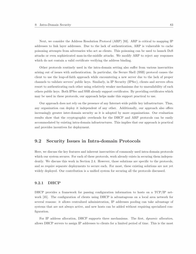
9. Intra-Domain Security 83
Next, we consider the Address Resolution Protocol (ARP) [93]. ARP is critical to mapping IP
addresses to link layer addresses. Due to the lack of authentication, ARP is vulnerable to cache
poisoning attempts from adversaries who act as clients. This poisoning can be used to launch DoS
attacks or even sophisticated man-in-the-middle attacks. We modify ARP to reject any responses
which do not contain a valid certificate verifying the address binding.
Other protocols routinely used in the intra-domain setting also suffer from various insecurities
arising out of issues with authentication. In particular, the Secure Shell (SSH) protocol causes the
client to use the leap-of-faith approach while encountering a new server due to the lack of proper
channels to validate servers’ public keys. Similarly, in IP Security (IPSec), clients and servers often
resort to authenticating each other using relatively weaker mechanisms due to unavailability of each
others public keys. Both IPSec and SSH already support certificates. By providing certificates which
may be used in these protocols, our approach helps make this support practical to use.
Our approach does not rely on the presence of any Internet-wide public key infrastructure. Thus,
any organization can deploy it independent of any other. Additionally, our approach also offers
increasingly greater inter-domain security as it is adopted by more organizations. Our evaluation
results show that the cryptographic overheads for the DHCP and ARP protocols can be easily
accommodated by existing intra-domain infrastructures. This implies that our approach is practical
and provides incentives for deployment.
9.2 Security Issues in Intra-domain Protocols
Here, we discuss the key features and inherent insecurities of commonly used intra-domain protocols
which our system secures. For each of these protocols, work already exists in securing them indepen-
dently. We discuss this work in Section 2.4. However, those solutions are specific to the protocols,
and so require separate deployments to secure each. For most, these existing solutions are not yet
widely deployed. Our contribution is a unified system for securing all the protocols discussed.
9.2.1 DHCP
DHCP provides a framework for passing configuration information to hosts on a TCP/IP net-
work [35]. The configuration of clients using DHCP is advantageous on a local area network for
several reasons: it allows centralized administration, IP addresses pooling can take advantage of
systems that are not always active, and new hosts can be added without requiring specialized con-
figuration.
For IP address allocation, DHCP supports three mechanisms. The first, dynamic allocation,
allows DHCP servers to assign IP addresses to clients for a limited period of time. This is the most

9. Intra-Domain Security 84
popular mode of DHCP operation, typically used for client machines. It allows unused IP addresses
to be returned back to the pool of available IPs, and IP addresses to change without updates to
the network. The second, static DHCP, allows network administrators to specify permanent IP
addresses for specific clients, identified by their MAC addresses. Each time a DHCP request is
issued from a given MAC, the same IP address is supplied, causing the machines to continuously be
available at the same IP address. The third, manual allocation, allows the network administrator to
manually assign IP addresses to a clients, and DHCP is used simply to convey the assigned address
to the client. Static DHCP and manual allocation are typically used for servers. In addition to IP
configuration, DHCP is also used to convey other bootstrapping parameters to the clients, including
the IP address of the default router, IP addresses of DNS servers, and the subnet mask.
DHCP has no built-in authentication mechanism. As a result, it suffers from various insecurities.
First, an adversary can join the network as a DHCP server and provide clients with misleading
configuration information which could be exploited later on. For example, a DHCP server under
an attacker’s control could bootstrap hosts with information about a router in its control instead of
the one they are supposed to use, thus redirecting traffic to destinations not intended by the host.
Second, an adversary could join as a client on the network, spoof its MAC address, and generate
bogus requests to exhaust the pool of IP addresses at the DHCP server. This would make legitimate
clients unable to acquire an IP address and effective launch a DoS attack on them.
9.2.2 ARP
ARP is used to map IP addresses to link layer (commonly MAC) addresses. For robustness, ARP
allows hosts and intra-domain routers to discover these mappings dynamically. It takes advantage of
the fact that many link layer technologies, including Ethernet, support broadcast. Before answering
an ARP query, a host or router first checks for the existence of the desired mapping in its cache. If
the desired mapping is not found there, it broadcasts the query. Each entity on the local network
receives the query but only the host whose IP address is contained in the query responds with its
MAC address. The recipient caches the mapping for subsequent use.
The insecurity in ARP arises because anyone can send ARP queries on the network and anyone
can respond to them. In particular, an adversary could send an incorrect response to an ARP query
and cause poisoning of ARP caches. While incorrect entries in general could cause DoS attacks on
legitimate clients, a concerted manipulation of entries in the ARP cache allows an attacker to launch
a man-in-the-middle attack and eavesdrop or alter traffic.
9.2.3 SSH
SSH is an application layer protocol used for secure remote access. It also allows for secure file
transfers and port forwarding. Once established, the communication between parties in the SSH

9. Intra-Domain Security 85
protocol is secure; however, there are weaknesses in verifying that the remote server being connected
to is legitimate.
In SSH, the clients are asked to verify the public key associated with the server they request. The
user generally has two options, either obtaining the public key fingerprint in an out-of-band fashion,
or simply taking a “leap of faith” and accept the key without verifying it. Upon doing so, the public
key is entered into a database and a warning issued if a different key is ever presented for the same
host. The leap-of-faith approach provides protection against subsequent man-in-the-middle attacks,
but does not protect against such an attack during the initial connection.
9.2.4 IPSec
The IPSec protocol, a popular virtual private network (VPN) protocol, allows hosts to establish
cryptographic tunnels to transmit data. These packets can be simply authenticated or authenticated
and encrypted. IPSec does a good job of securing the communications over the VPN. The problem
we address is the method IPSec uses to authenticate clients.
IPSec requires both of the communicating end-hosts to be configured with the shared credentials
or public keys of the other participating end-host, which can increase administrative overheads.
Instead, many large networks use pre-shared secrets, which have undesirable security properties.
9.3 Overview of our Approach and Threat Model
9.3.1 Threat Model
We focus on two categories of attacks. The first are attacks that adversaries can launch by mas-
querading as legitimate clients or servers. The second are attacks that legitimate clients and servers
can launch by impersonating other clients or servers. In both of these categories, we ignore attacks
that simply aim to congest links with spurious packets and in turn launch DoS attacks. We assume
that hosts that simply flood the network with traffic will be quickly identified by an administrator
and removed from the network.
9.3.2 Overview of our Approach
Our approach assumes that each organization has generated a (public, private) key pair for use in
its domain locally and that each server and client in the domain is configured with the public key
of the domain. We also assume that the domain uses its private key to sign the public key of each
server in the organization in the form of a certificate. These certificates are used to authenticate the
servers in various intra-domain protocols.
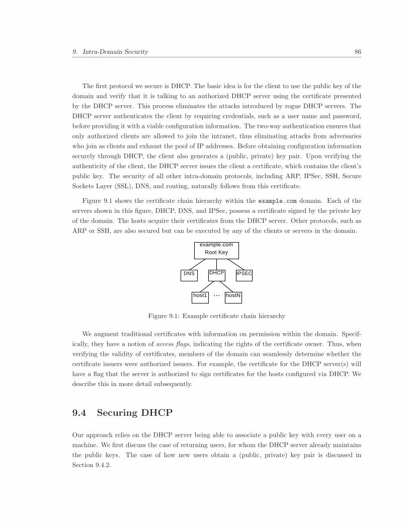
9. Intra-Domain Security 86
The first protocol we secure is DHCP. The basic idea is for the client to use the public key of the
domain and verify that it is talking to an authorized DHCP server using the certificate presented
by the DHCP server. This process eliminates the attacks introduced by rogue DHCP servers. The
DHCP server authenticates the client by requiring credentials, such as a user name and password,
before providing it with a viable configuration information. The two-way authentication ensures that
only authorized clients are allowed to join the intranet, thus eliminating attacks from adversaries
who join as clients and exhaust the pool of IP addresses. Before obtaining configuration information
securely through DHCP, the client also generates a (public, private) key pair. Upon verifying the
authenticity of the client, the DHCP server issues the client a certificate, which contains the client’s
public key. The security of all other intra-domain protocols, including ARP, IPSec, SSH, Secure
Sockets Layer (SSL), DNS, and routing, naturally follows from this certificate.
Figure 9.1 shows the certificate chain hierarchy within the example.com domain. Each of the
servers shown in this figure, DHCP, DNS, and IPSec, possess a certificate signed by the private key
of the domain. The hosts acquire their certificates from the DHCP server. Other protocols, such as
ARP or SSH, are also secured but can be executed by any of the clients or servers in the domain.
example.comRoot Key
DHCP IPSECDNS
host1 hostN...
Figure 9.1: Example certificate chain hierarchy
We augment traditional certificates with information on permission within the domain. Specif-
ically, they have a notion of access flags, indicating the rights of the certificate owner. Thus, when
verifying the validity of certificates, members of the domain can seamlessly determine whether the
certificate issuers were authorized issuers. For example, the certificate for the DHCP server(s) will
have a flag that the server is authorized to sign certificates for the hosts configured via DHCP. We
describe this in more detail subsequently.
9.4 Securing DHCP
Our approach relies on the DHCP server being able to associate a public key with every user on a
machine. We first discuss the case of returning users, for whom the DHCP server already maintains
the public keys. The case of how new users obtain a (public, private) key pair is discussed in
Section 9.4.2.

9. Intra-Domain Security 87
Discovery:
Offer:
Request:
Acknowledgment:
Settings
Settings
Settings
Client Server
(a) Traditional DHCP
Discovery:
Offer:
Request:
Acknowledgment:
Nonce , K
Settings, Nonce , Certificates , { Settings, Nonce , Nonce }
C
S C S KSPriv
Settings, Nonce , K , { Settings, Nonce , Nonce , K }C’ S C’ KCPrivC
Pub
Settings, Certificate , { Settings, Nonce }C C’ KSPriv
S
CPub
Client Server
CPub
(b) DHCP secured by our approach
Figure 9.2: Traditional DHCP protocol compared to our secured DHCP implementation
9.4.1 Proposed DHCP Operation
The process of obtaining an IP address and configuration information through the traditional version
of DHCP in use today consists of the following four steps, shown in Figure 9.2(a). In the first step,
the client wishing to join the network issues a broadcast DHCP Discovery message on the network.
The client seeks an IP address through this message. This message may also indicate the address
and other settings the client would prefer to receive, which is common for a client returning to a
network and attempting to reclaim a previously used address. The DHCP server responds to the
client in unicast with a configuration Offer message which includes the IP address it is offering.
This message may include settings such as subnet information, a default gateway, DNS servers,
lease length, and address information for the host, among other things. Next, the client broadcasts
a Request message for the offered configuration if it likes the offer. If the configuration is still
available, the server finally responds with an Acknowledgment message, at which point the client is
configured according to the offered information.
Our approach does not introduce any new messages in the DHCP exchange. However, we modify
each of the four messages in the DHCP exchange to provide security. The modified DHCP exchange
is shown in Figure 9.2(b). The description of each of the modified messages follows.
Discovery Message: Just like traditional DHCP, this message is broadcast to find any DHCP
servers on the network segment. We introduce two additional parameters in this message. The first
is the public key of the user on a machine, which is used by the DHCP server to retrieve the previous
settings for this client. If the client possesses multiple MAC addresses, the MAC address contained
in the link layer header of the packet can be used to retrieve the appropriate settings. The second
parameter we introduce is a nonce value. This is a randomly generated bit string which helps ensure
the freshness of the response from the server.
Offer Message: Upon receiving the Discovery message, the DHCP server determines the offer

9. Intra-Domain Security 88
to make. This step is similar to its counterpart in traditional DHCP except that the public key
of the client is used to retrieve previous settings instead of simply the MAC address. To prevent
rogue DHCP servers from misconfiguring the client, we require that the server provide proof that it
is legitimately associated with the domain and that it is not simply replaying an older response. To
meet the first requirement, the server includes a full certificate chain to a root of the domain. The
client can verify this chain by using the public key of the domain that all clients are configured with.
To meet the second requirement, the DHCP server replies with a signature covering the nonce value
sent by the client in the DHCP discovery message. The server also includes its own nonce value
to ensure the client’s liveliness. To prove authenticity, and to prevent modification of the values in
transit, the offered settings and nonce value are signed by the DHCP server’s private key.
Request Message: Upon receiving a DHCP offer, the client must determine whether to accept
the offer. To avoid being misconfigured, in our scheme, it confirms that the offer is valid. It first
determines if the certificate chain in the Offer message includes a certificate signed by the domain
key, which the client also trusts. If so, the client can use the certificate chain to verify each certificate
and subsequently the DHCP server. If no trusted entity is found, the offer should be rejected. Once
the public key for the DHCP server is validated, the client verifies that the signature for the offer is
correct. Next, the client evaluates the offer itself, just as in traditional DHCP. If it decides to accept
the offer, it broadcasts a DHCP Request message for the settings offered. The message includes the
desired settings used in the DHCP Offer message. The message also includes the client’s public
key and a new nonce value that must be echoed by the server. The settings, the server’s last nonce
value, the client’s new nonce, and public key are signed using the client’s private key. By signing
the server’s last nonce value, the client proves the Request message is not being replayed.
Acknowledgment Message: In the final step, the DHCP server constructs an Acknowledgment
message by providing the settings, the nonce value from the client, and a certificate for the host to
use with other intra-domain protocols. The settings and nonce value are signed with the server’s
private key and the signature is included in the message. The client can verify the signature using
the certificate information obtained from the DHCP Offer message. Further, the client can confirm
its issued certificate is valid by using the provided certificate chain and the DHCP server’s public
key.
Example Certificate: An example of the certificate issued by the DHCP server under our scheme
is shown in Figure 9.3. Though conceptually similar to the SSL certificates we use everyday, this
certificate contains additional information. First, it indicates binding information for the host,
including the host name, IP address, and MAC address. Next, it contains the access flags that
indicate what is allowed. For example, a typical host will not be allowed to issue certificates or run
an SMTP server but will be allowed to establish IPSec connections. Finally, the certificates contain
issue date and expiration date. The issue date is the time at which the DHCP server issues the

9. Intra-Domain Security 89
certificate and the expiration is set to when the DHCP lease will expire1.
CertificateIssuer:
Name: dhcp.example.com
Subject:
Name: client-14.dhcp.example.com
IP: 1.2.3.4
MAC: 00:01:02:03:04:05
Issue Date: 2008-01-01-23-59
Expire Date: 2009-01-01-23-59
Access Flags:
IPSec Access: ALLOWED
SMTP Server: DENIED
Client Public Key:
00:cb:15:11:a4:32:89:b5:de:c1...
Figure 9.3: Example of a certificate under our approach
9.4.2 Bootstrapping New Clients
When a new client first connects to the network, or it connects with a different user than has
been seen on it before, it is unrecognized by the network and considered unauthorized. To be
bootstrapped, the client must first generate a (public, private) key pair for the current user. It then
approaches the DHCP server through the DHCP Discovery message as before. When the DHCP
server fails to find an entry for this client’s public key, it isolates the client and requires the client
to authenticate itself using alternative organization authentication services, such as RADIUS [100]
or a captive portal, which is a secure Web authentication page the client will be directed to instead
of their intended destination. When the client authenticates, it provides the user’s public key and
the client’s MAC address to the authentication system, which then communicates the key and MAC
address to the DHCP server. The DHCP server then knows that this is a valid public key for some
user on the system with the given MAC address, but does not have any settings associated with
it. The authentication system can refuse to accept a new public key for users for which it already
knows several public keys. This step ensures that the DHCP server knows the public keys for each
authorized user, every valid user in an organization is allowed to acquire only one key per MAC
address, and each user is limited to a low number of public keys concurrently registered, preventing
the user from spoofing a large number of MAC addresses and using them to exhaust the pool of IP
addresses from the DHCP servers.
Notice that our approach does not attempt to prevent MAC address spoofing on a small scale.
Further, it does not prevent a user from being associated with several MAC addresses, which may
1For applications users use remotely, such as IPSec or SSH, the certificate does not require MAC, IP, or DNS hostname information. Instead, a separate longer-term certificate can be used. We discuss this in detail in Section 9.5.2.

9. Intra-Domain Security 90
be useful if a user has multiple computers or network interfaces (e.g. wired or wireless). It also does
not prevent a user from changing its MAC addresses at any point, which may be useful in the rare
case where two devices have identical MAC addresses.
9.4.3 Formal Discussion of Security
In the secure DHCP protocol, we must ensure the legitimacy of clients and servers engaging in
the protocol. We must also ensure that no adversary is able to disrupt correct protocol operation.
Further, no entity, including adversaries or legitimate clients, should be able to acquire any more
than one IP address per MAC address, subject to a maximum allowable number of MAC addresses.
These requirements can be translated into the following five properties:
• the DHCP server is trustworthy
• the offered settings are not manipulated by an attacker
• messages are not replayed
• each client possesses exactly one (public, private) key pair at any point
• the client holds the private key associated with the offered public key
We now justify how our protocol design preserves the above properties. The first property,
trustworthiness of the DHCP server, is addressed by the certificate chain. If a DHCP server provides
a valid certificate issued by a party trusted by the client, in this case the domain key, the client can
be assured that the DHCP server is valid if the digital signature is correct.
The second property, that the offered settings are not manipulated by an attacker, holds because
we require that the settings offered by the DHCP server are signed.
The third property, that messages are not replayed, holds because our protocol requires that
both the client and the server use nonces to ensure the freshness of their messages. Both the client
and server put fresh nonces in their messages and the other party echoes them for verification. To
prevent modification of nonces in transit, we require for them to be signed when echoed.
The use of RADIUS server or captive portal ensures that each user possesses exactly one valid
(public, private) key pair per client at any point. Thus, the fourth property is satisfied. This
property ensures that the clients are unable to secure any more than one IP address per allowable
MAC address.
Finally, the fifth property, that the client holds the private key corresponding to the public key
it offers to the DHCP server, holds because we require the clients to issue digital signatures, which
require the use of private key.

9. Intra-Domain Security 91
In our protocol, the DHCP server must perform a public key operation before the client has proven
its authenticity. This can lead to DoS attacks targeting the DHCP server’s processor resources.
Instead, the DHCP server can require the client to reply to a nonce value proving its liveness before
generating a signature. This extra round-trip could optionally be required only when the server is
under heavy processor load.
9.5 Securing Other Intra-domain Protocols
In designing our intra-domain security approach, we leverage the DHCP server as the gatekeeper for
the network. It distributes certificates to hosts in a secure and verifiable manner and thus provides
them with a mechanism to prove their authenticity in later communications, even when utilizing
services, such as SSH, from outside the intranet. We now describe how our approach secures other
intra-domain protocols.
9.5.1 Securing ARP and Preventing IP Spoofing
We secure ARP through adding additional operations to the ARP protocol. Under our scheme, an
end host transmits the regular ARP request as is done today. However, when replying to an ARP
request, it must include the certificate it obtained from the DHCP server showing the IP and MAC
binding along. The requester can then verify the certificate to confirm that the response given by the
responder is accurate. ARP responses without accompanying valid certificates verifying the address
binding would be rejected. This simple extension eliminates both ARP cache poisoning attempts
as well as any man-in-the-middle attacks. Also notice that even though ARP will require expensive
public key operations under our scheme, they only have to be done on the order of once every 15
minutes or so, when ARP cache entries expire. We evaluate these overheads in detail in Section 9.8.
While the association between MAC and IP addresses is secured by our modifications to ARP,
a host can still spoof a valid MAC and IP combination. This can be prevented in two ways:
by proving authenticity in each packet or leveraging DHCP snooping. To prove authenticity at
connection establishment, a client may sign their message and include a secret key encrypted using
the server’s public key. In subsequent messages, the client and server may simply use a nonce and
the secret key to construct a message authentication code and embed this code in the body of each
message, allowing the other client to verify its authenticity. To avoid a DoS attack, the server may
force the client to respond to a nonce before verifying the client’s signature and decrypting the secret
key for usage in subsequent messages.
While effective, providing authenticity of each message incurs a modest additional overhead
at the end-hosts. Instead, DHCP snooping by the switching infrastructure can leverage network
topology to avoid requiring per-packet verification. As mentioned before, switches today sometimes

9. Intra-Domain Security 92
employ DHCP snooping to prevent ARP cache poisoning and IP spoofing. Essentially, such switches
monitor DHCP traffic to create allowable MAC address and IP bindings, and associate them with
individual switch ports. When a packet arriving on an interface does not match the binding, the
packet is discarded. With our approach, switches can employ stronger DHCP snooping protection.
While we do not need DHCP snooping to prevent ARP cache poisoning, we can leverage it to
protect the intranet against IP spoofing because without it, our approach can provide this protection
but with high overhead. Essentially, we require the switches to be configured with the the public
key of the domain and DHCP server(s). The switch would then permit any DHCP discovery or
request messages, but only permit DHCP offer or acknowledgment messages that were signed by
the DHCP server. Upon seeing a DHCP acknowledgment for a host, the switch would verify the
acknowledgment and add the MAC, IP address, and switch port associated with the end-host to its
white-list, allowing the host to send regular traffic on the network. Upon receiving traffic from hosts
not in the white-list, the switch would drop the packet and issue an ARP request for the IP address
associated with the end-host. If the host issues an ARP reply with a valid certificate issued by the
DHCP server, and a signature showing possession of the associated private key, the switch would
add the host to the white-list.
9.5.2 Securing SSH
As mentioned before, SSH takes a leap-of-faith approach while verifying servers to clients. By
leveraging the certificates distributed by the DHCP server, clients can securely verify servers. The
SSH protocol already allows a certificate to be incorporated in the protocol to authenticate the public
key [126]. Upon connection establishment, the SSH server presents a certificate with its public key.
If the certificate is issued by a trusted party, contains the public key, and is verified successfully, the
client can trust the public key for the server. This is supported in the SSH Tecita software from
SSH communications [111], and is supported by OpenSSH [119] with a patch [92].
The scheme we have discussed so far allows SSH to work seamlessly when both machines are
members of the intra-net. However, if a host leaves the intra-net and its DHCP lease expires, the
associated certificate will also expire, preventing the remote client from being able to authenticate
with members of the domain. To combat this problem, we propose the DHCP server issue a client
two certificates: one containing the client’s MAC, IP, and host name bindings as before and another
that omits these fields, making the expiration independent of the DHCP lease, allowing it to have a
much later expiration date. When interacting from outside the domain, the client can provide this
certificate. Under this approach, the other clients can only identify the remote machine by its public
key. This certificate may only be used for remote machines; machines residing in the intranet must
use the certificate containing their MAC, IP address, and host name.
Our system provides infrastructure that facilitates certificate usage for SSH. This can be used

9. Intra-Domain Security 93
to allow host verification, preventing man-in-the-middle attacks. However, user authentication is a
separate issue that must be handled by the SSH protocol itself.
9.5.3 Eliminating IPSec Insecurity
As mentioned before, some IPSec deployments rely on shared credentials for the protocol. When
used solely for confidentiality, these organizations may post these pre-shared secrets on public Web
pages to enable dissemination. Unfortunately, such an approach thwarts efforts to authenticate the
other IPSec participant when performing keying. This weakness could be eliminated by simply using
public key cryptography; unfortunately, these public keys are often not available at the client or at
the server today. However, by leveraging the certificate of the IPSec server under our scheme and the
certificates possessed by individual end hosts, our approach can remove this insecurity. The IPSec
protocol already has support for using certificates to identify IPSec participants. So, our approach
requires no change to the protocol. As with SSH, IPSec may use a separate certificate for remote
machines to confirm the machine is a member of the domain, but not be tied to a specific MAC, IP
address, or host name. This separate certificate may only be used for remote hosts.
9.5.4 Securing Intra-domain SSL
Certificates issued by the DHCP server can also be used to authenticate servers for SSL. Accordingly,
if authorized, any machine in the domain may operate an SSL server which will be trusted by all
other members of the domain without requiring additional infrastructure.
9.5.5 Securing Intra-domain Aspects of DNS
Since the DNS server in our scheme possesses a certificate that any entity in the network can verify
using the public key of the domain, we can enable DNSSEC within the domain even irrespective of
who else deploys. This in turn ensures that DNS messages can be authenticated and checked for
integrity.
Also, when establishing DHCP connections, clients may request customized host names to be
associated with their machines, using the DHCP fully qualified domain name option [113]. Under
the option, the DHCP server or the client may notify the DNS server of the update to the A
record mapping the domain name to the IP address. Since the DHCP server is responsible for IP
addresses, only it can notify the DNS server to update the PTR record mapping the IP address to the
domain name. Our system enables two improvements to this process. Since the DHCP server has a
certificate, the DNS server is now provided with a way to authenticate the updates requested by the
DHCP server if desired. If the responsibility for notifying the DNS server of the updates is left to the
9. Intra-Domain Security 94
client, it can sent its certificate to the DNS server along with the update. The certificate is evidence
of the mapping, therefore proving to the DNS server that the requested mapping is correct. Since
the DNS server now knows the mapping is legitimate, it can update both the A and PTR records
from the client request instead of just the A record.
9.5.6 Securing Intra-domain Routing
By eliminating MAC and IP address spoofing within a domain, and by providing certificates for
routers to perform mutual authentication, our approach allows routers to ensure that messages are
not forged. In [52], the authors discuss how routing can be secured using a self-signed certificate
model that evolves into a global public key infrastructure. In this work, we use keys signed by the
domain root of trust. However, our approach also allows the incremental evolution of a public key
infrastructure.
9.6 Distributing Keys for a Domain
Many security proposals suggest or rely upon a global public key infrastructure to distribute public
keys and to construct chains of trust. Unfortunately, efforts to deploy a public key infrastructure
have languished, so reliance upon such an infrastructure is impractical. Instead, we design our
protocol to function independently, but also embrace a public key infrastructure should one become
available. Accordingly, we describe various ways in which a domain can procure a (public, private)
key pair.
9.6.1 Independent Operation
Our approach is designed to be successful without requiring a public key infrastructure. We discuss
two different approaches in which clients can learn the public key of the domain.
In SSH, upon encountering an unrecognized public key, the user is asked to verify the key
fingerprint. Upon doing so, the public key is retained as trusted for all subsequent communication.
To verify the fingerprint, the user may receive documentation from their network administrator and
compare the documented fingerprint with the value they receive. In other cases, the users may
simply take a “leap of faith” and trust the public key without verification, which protects the users
from subsequent man-in-the-middle attacks as long as the initial connection was authentic.
While the leap-of-faith approach is problematic in the case of SSH because it needs to be done
for each individual machine, we can leverage it to bootstrap clients with domain’s public key in an
automated manner. The reason this is a reasonable approach for us to consider this approach is

9. Intra-Domain Security 95
because there is exactly one key in question for the entire domain. Accordingly, the user would need
to verify only a single fingerprint rather than a key for each machine. By reducing the verification
overhead, more users may be encouraged to manually verify the key fingerprint. Users often must
perform some security configuration upon first entering a network, such as registering a MAC address
or configuring their machine for wireless security. Accordingly, this simple verification is unlikely to
pose a significant barrier to usage.
Another approach is to simply pre-provision machines with the public key for the domain. En-
terprises often create a customized disk image for the operating system and applications they use
and apply it to all new machines. Other organizations or ISPs may distribute CDs that configure
machines for the network; such CDs could install the domain key onto the target machine. Because
public key cryptography is being used, rather than symmetric keys, identical information can be
widely distributed, easing administrative overheads. By installing the domain key, administrators
can ensure all their machines can automatically verify legitimate machines on the domain without
requiring human intervention.
9.6.2 Certificate Authorities as Trust Anchors
In the SSL protocol, certificate authorities (CAs) are used to authenticate systems. Upon encounter-
ing a site employing SSL, the browser examines the certificate offered by the server. If the certificate
is signed by a trusted root CA, it is considered valid and communication can proceed. Certificates
may also be members of a certificate chain, in which certificates are linked together in signing re-
lationships. To verify a member of the certificate chain, the client must obtain all the certificates
preceeding it on the chain and verify the signatures in turn. In our protocol, we can leverage a
similar approach for verifying a domain. If a domain were to obtain a certificate designated for
domain-wide trust from a CA, it could provide this certificate to authenticate itself to any client
that trusts the same CA. This would allow a client to automatically establish a trust relationship.
While certificate authorities have their own limitations, this approach has been widely successful on
the Internet.
9.6.3 DNS Security for Key Distribution
The DNS provides a distributed database for the Internet, allowing the translation of host names
to IP addresses. DNSSEC [11] can be used to provide authenticated information in the DNS. While
the deployment of DNSSEC is currently low, if it were well deployed, DNS could be leveraged to
distribute certificates [63] in domains using DNSSEC, based on trust of well known entities such as
the TLDs or the DNS root. A client can use DNSSEC in order to establish the certificate chain
to trust information contained in the domain’s DNS records, including certificates stored in a DNS
record. This would allow the client to learn the DNS record in an automated manner through DNS.
9. Intra-Domain Security 96
9.7 Revocation of Certificates
Revocation is an important aspect that must be considered in order to ensure that the rights of
misbehaving legitimate entities in a network can be terminated. One approach to accomplish this
goal is to filter traffic to a machine that has become unauthorized or simply disconnect it from the
network. Other options exist, which we discuss next.
Several mechanisms are in place to revoke certificates in the inter-domain scenarios, such as
in the case of SSL. Certificate revocation is a major concern in such protocols. If the private
key associated with a certificate is compromised by an attacker, the certificate must be marked
as invalid to prevent the attacker from impersonating the victim. SSL, a popular certificate-based
security protocol, can use two different approaches to revoke certificates: a certificate revocation list
(CRL) [30] or the Online Certificate Status Protocol (OCSP) [82]. In CRLs, the certificate authority
publishes a signed list of revoked certificates and clients must check this list each time they encounter
a certificate to ensure that the current certificate has not been revoked. The OCSP protocol allows
hosts to verify the status of a certificate on-demand to ensure its validity. These approaches may
incur high processing and bandwidth overhead at the certificate authority, limiting scalability. As a
result, certificate revocation checking is not enabled by default in most popular Web browsers.
A revocation mechanism similar to that used in the inter-domain setting can be used for intra-
domain, only more efficiently. Intra-domain certificate revocation has several advantages over inter-
domain revocation. First, local area networks typically have centralized administration which is
trusted both to issue certificates to domain members and the authority to decide when they must
be revoked. Second, members of the domain are often co-located on high bandwidth links. This
allows clients to routinely query for revocation lists, due to greater capacity, lower latency, and since
revocation servers are more likely to be available. As a result, clients can routinely obtain CRLs
or issue OCSP queries for the hosts they contact. The frequency with which the client caches are
updated can be configured on a per-domain basis and this setting distributed with other DHCP
information. This allows domains to balance rapid revocation with network overheads.
Other Uses of Revocation: While certificate revocation is traditionally used when a public key
is compromised, revocation could also be issued if member of the domain should have privileges
rescinded immediately. However, revocation is not required when additional privileges are granted.
Instead, a machine receiving additional privileges can simply request a new certificate indicating
this before the old one expires. This usage of revocation allows a domain to effect access control in
addition to authenticating machines.
Revocation of Domain Key: While certificate revocation is straight-forward for entities belonging
to the domain, it is much more challenging for the domain key. Were the domain key compromised,
a revocation self-signed by the domain key must be issued, invalidating the key on a domain-wide
basis. A new domain key would then need to be established using one of the methods described in

9. Intra-Domain Security 97
Section 9.6. Like certificate authorities in the Internet, organizations would have significant incentive
to avoid such a scenario. Accordingly, the domain key would likely be tightly secured and only used
to issue certificates for infrastructure components, such as the DHCP server, limiting exposure.
9.8 Implementation and Evaluation
To evaluate our proposed scheme, we implemented the modified ARP and DHCP protocols and
then experimentally analyzed their performance based on the usage of these protocols on a medium
and large network. We focused on these two because these are the only cases where we introduce
new overheads to the protocols. In the remainder of the intra-domain protocols discussed in this
paper, there is already support to incorporate the certificate-related mechanisms; we have merely
facilitated their usage in a seamless way.
All of the performance trials were conducted on a machine with a Pentium IV 1.8 GHz processor
with 512MBytes RAM. To measure the timings, we use the RDTSC instruction, which can be used
to measure the elapsed cycle count, yielding nanosecond timing resolution.
9.8.1 DHCP
DHCP is implemented as an option for BOOTP, which was designed to allow hosts to obtain IP
addresses automatically [35]. To evaluate our changes to the DHCP protocol, we implemented the
entire protocol and timed each of the cryptographic operations. We created our DHCP packets
by populating the standard DHCP packet header and adding DHCP options for each of the new
fields that need to be transmitted in the packets under our version of the protocol. In total, we
implemented seven new option types allowed by RFC 2131 [35] as “reserved for local use”. These
options allowed the specification of a client public key, client and server nonce values, a signature of
the DHCP message, certificates for the DHCP client and server, and supporting certificates required
to verify the client and server certificates.
To implement the cryptographic components in the messages, we used the Botan cryptographic
library for C++ [73]. This library provides an extensive set of functions allowing us to create
certificates, generate public keys, sign and verify messages, and implement a certificate authority.
In creating our experiments, we generated an RSA (public, private) key pair and root certifi-
cate for the example.com domain. We then created another RSA key pair and certificate for the
dhcp.example.com DHCP server, and signed this certificate with the domain root key. For each
DHCP client, we generated a DSA key pair. We chose DSA instead of RSA for the clients because
of its faster signing and verification operations. We chose to use RSA for the domain and DHCP
server keys due to their smaller certificates, as these must be included in the certificate chains for
each DHCP offer message.
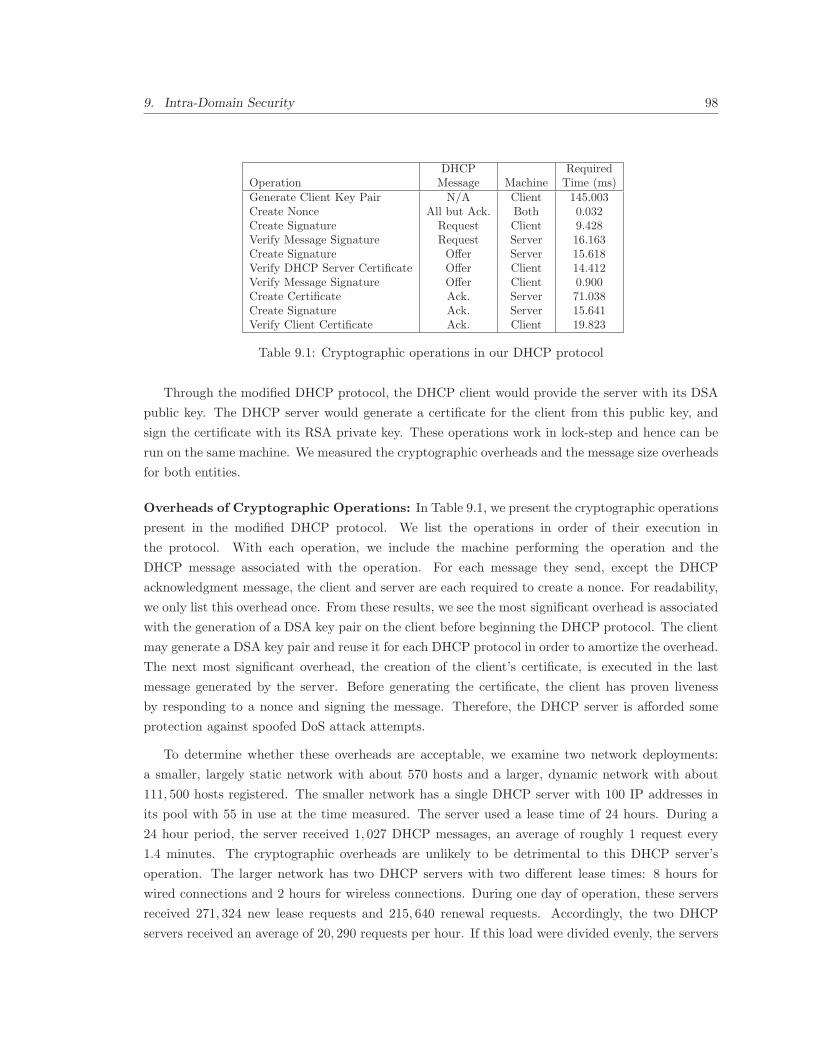
9. Intra-Domain Security 98
DHCP RequiredOperation Message Machine Time (ms)Generate Client Key Pair N/A Client 145.003Create Nonce All but Ack. Both 0.032Create Signature Request Client 9.428Verify Message Signature Request Server 16.163Create Signature Offer Server 15.618Verify DHCP Server Certificate Offer Client 14.412Verify Message Signature Offer Client 0.900Create Certificate Ack. Server 71.038Create Signature Ack. Server 15.641Verify Client Certificate Ack. Client 19.823
Table 9.1: Cryptographic operations in our DHCP protocol
Through the modified DHCP protocol, the DHCP client would provide the server with its DSA
public key. The DHCP server would generate a certificate for the client from this public key, and
sign the certificate with its RSA private key. These operations work in lock-step and hence can be
run on the same machine. We measured the cryptographic overheads and the message size overheads
for both entities.
Overheads of Cryptographic Operations: In Table 9.1, we present the cryptographic operations
present in the modified DHCP protocol. We list the operations in order of their execution in
the protocol. With each operation, we include the machine performing the operation and the
DHCP message associated with the operation. For each message they send, except the DHCP
acknowledgment message, the client and server are each required to create a nonce. For readability,
we only list this overhead once. From these results, we see the most significant overhead is associated
with the generation of a DSA key pair on the client before beginning the DHCP protocol. The client
may generate a DSA key pair and reuse it for each DHCP protocol in order to amortize the overhead.
The next most significant overhead, the creation of the client’s certificate, is executed in the last
message generated by the server. Before generating the certificate, the client has proven liveness
by responding to a nonce and signing the message. Therefore, the DHCP server is afforded some
protection against spoofed DoS attack attempts.
To determine whether these overheads are acceptable, we examine two network deployments:
a smaller, largely static network with about 570 hosts and a larger, dynamic network with about
111, 500 hosts registered. The smaller network has a single DHCP server with 100 IP addresses in
its pool with 55 in use at the time measured. The server used a lease time of 24 hours. During a
24 hour period, the server received 1, 027 DHCP messages, an average of roughly 1 request every
1.4 minutes. The cryptographic overheads are unlikely to be detrimental to this DHCP server’s
operation. The larger network has two DHCP servers with two different lease times: 8 hours for
wired connections and 2 hours for wireless connections. During one day of operation, these servers
received 271, 324 new lease requests and 215, 640 renewal requests. Accordingly, the two DHCP
servers received an average of 20, 290 requests per hour. If this load were divided evenly, the servers
9. Intra-Domain Security 99
processed about 2.82 requests per second. The cryptographic overheads at the server on our test
machine were about 119ms per client request. If only these overheads are considered, the servers
could process 8.44 requests per second from cryptographic perspective, even without exploiting any
parallelism. We note that even though our test server is quite modest, it could easily accommodate
the requirements of this large network. Accordingly, we believe our proposed solution is feasible for
both these networks.
Message Sizes: While evaluating our implementation, we examined the size of each message in
the modified DHCP protocol. The DHCP discovery and request messages easily fit within a single
Ethernet frame, requiring 955 and 1, 025 bytes respectively. Unfortunately, the DHCP offer and
acknowledgments, which require 2, 313 and 1, 866 bytes respectively, exceed the standard 1, 500 byte
MTU for Ethernet. While some networks may use jumbo frames [58], which can easily hold these
messages, others will require the packets to be split into two frames. Fortunately, this fragmentation
does not increase the number of round-trips in the protocol, causing the protocol to be largely
unaffected by these larger messages.
9.8.2 ARP
The operations required in the modified ARP protocol are a proper subset of the functionality in
the modified DHCP protocol. Accordingly, we examine the cryptographic overheads and evaluate
whether they are feasible in large networks.
Cryptographic Operation Overheads: Hosts issuing ARP requests have no extra overheads
when creating the request. However, they must verify the certificates in any requests they receive,
an operation which takes approximately 19.8ms on our test machine, as shown in Table 9.1. Hosts
responding to ARP requests must provide their own certificates in addition to the ARP reply header.
This operation requires no cryptographic overhead. Hosts responding to ARP requests containing
nonce values must also generate a signature over the message, which takes 9.4ms on our test machine.
Both of these overheads seem acceptable for hosts, which typically issue ARP requests or replies
relatively infrequently.
These overheads become more acute for routers and Ethernet switches. We again turn to our
example network deployments to determine the feasibility of processing these ARP messages. The
smaller network is serviced by four Ethernet switches with a link to an external router. The ARP
cache expiration timer on these switches was approximately 5 minutes. We monitored the ARP churn
on one of these switches for a five minute window and found that 50 cached entries were removed
while 42 were added. The switches would only perform challenges on new cache entries in order to
ensure the mappings were valid. Accordingly, these switches would need to generate an ARP request,
a nonce value, verify a certificate, and verify a signature once every 7.14 seconds. Combined, the
cryptographic operations took 36ms on our test machine. We find that these overheads are acceptable
9. Intra-Domain Security 100
for this network. Our larger example network has 5 routers, with the busiest router peaking at about
21, 000 ARP cache entries. At peak times, a few thousand of ARP cache entries are added per hour.
We conservatively estimate a peak addition rate of half of the observed cache size, or 10, 500 entries
per hour, or approximately 3 per second. These routers must issue ARP queries for each of these
hosts and verify the certificates in the replies, an operation that takes 19.8ms on our test machine.
Accordingly, excluding non-cryptographic overheads, the router could issue and verify 50.45 requests
per second. Since the rate possible is an order of magnitude greater than the estimated peak rate, we
believe the router can accommodate this overhead. Routers, like hosts, must reply to ARP requests
from hosts. The router must reply to these requests as they do today, but also provide their own
certificate. However, this operation requires no cryptographic overheads. The router is unlikely to
leave the ARP cache of the switches connected to it; however, if this happens, the overhead would
be only 9.4ms, the time required to generate a signature, once per ARP cache expiration. We find
these overheads to be acceptable for these networks.
Message Sizes: As with DHCP, we examined the packet size of ARP requests and replies. A
regular host ARP request is just 28 bytes, the size of the ARP header. For ARP requests with
a nonce challenge, the request is 32 bytes, the size of the ARP header and a 4 byte nonce value.
ARP replies with a certificate are 1, 395 bytes in size. Each of these messages fits inside a regular
Ethernet frame. However, ARP replies with a certificate, nonce, and a signature are 1, 572 bytes
in size, exceeding the limit of an Ethernet frame. As indicated in the DHCP analysis, networks
employing jumbo frames can accommodate these larger packets without difficulty. However, for
other Ethernet networks, the message must be sent in two frames. Fortunately, this does not require
a round-trip, limiting the added overheads.
9.9 Conclusion
In this work, we introduced and evaluated a unified framework for authenticating and authorizing
machines within a domain. Our solution leverages public key operations in order to provide these
guarantees. While public key operations are considered high overhead, we evaluated the secure
versions DHCP and ARP protocols and found the performance is viable in both small and large-
scale networks. Several other issues are important to consider. We discuss them next.
Incrementally Deployable Public Key Infrastructure: While our protocol is designed to allow
an organization to independently deploy the approach, several deploying organizations can use this
infrastructure to create an inter-domain security scheme. Such a grass-roots approach to creating
a public key infrastructure has been suggested in other works [52]. By allowing networks to deploy
the approach independently and by providing local incentives, the approach can obtain greater
adoption. With this adoption, collaborating networks can then begin to use the protocol for inter-
domain communication. With larger deployment, a formal top-down hierarchy can begin to replace
9. Intra-Domain Security 101
the grassroots approach. Accordingly, this approach moves closer to being a unified mechanism for
authenticating hosts across the Internet.
Malicious Intra-domain Clients: There is always a possibility of malicious intra-domain clients
attempting to attack the architecture itself. Intra-domain DoS attacks, for example, could be
launched by clients attempting to overwhelm other clients or the DHCP server. However, clients are
isolated until they have authenticated with the DHCP server, protecting the rest of the network.
Once they have authenticated, if they launch an attack, these clients can simply be ignored by the
victim machines, since the clients will be unable to spoof their addresses. Attackers may target
the DHCP server, since it is required to create and sign a certificate, a cryptographically intense
operation. However, this certificate signing does not happen until after the client has proven liveness
by replying to a nonce value, limiting the ability of the client to spoof attacks. Further, Ethernet
switches can easily rate-limit the number of DHCP and ARP requests issued by a client, limiting
the attack’s success.
Compatibility with IPv6: While we have largely focused on the behavior of an IPv4 network
throughout this paper, our approach is compatible with IPv6 as well. When used with a DHCP
server in IPv6, certificates are issued much as they are in IPv4. However, the IPv6 protocol does
not use the ARP protocol. Instead, neighbor discovery is used. This protocol can be modified in
a similar fashion as the ARP protocol in order to provide cryptographic bindings as well. While
IPv6 can be used for stateless auto-configuration, such configuration runs contrary to the desire for
registering or authenticating with a centralized device. Accordingly, auto-configuration is unlikely
to be deployed in a network where heightened security is a goal.

10
Conclusion
The Internet is an important component of computing and of society as a whole. With its phe-
nomenal growth, the Internet has become stressed in terms of address space and routing scalability.
Further, it is tied to a single addressing scheme, raising the costs associated with change. However,
these problems are not intractable.
10.1 Summary of Contributions
In this dissertation, we explored a way forward: we eliminated IP addresses in the Internet and
replaced them with a system that has better performance, routing scalability, and embraces evolution
of host addressing. In our system, we embraced a split between routing locators and host identifiers
and used ASNs to forward packets. ASNs yield smaller routing tables, faster packet forwarding, and
can be used independent of the host addressing scheme. To perform intra-domain packet forwarding
and to identify hosts, we used DNS host names. Host names are already widely used by Internet
users and using them directly allowed us to reduce the requirements on the DNS while solving the
address space exhaustion problem in IPv4. However, other host addressing schemes can be designed
and ASN-based routing will still provide routing scalability.
Host names also allow us to create a unified authentication architecture to solve intra-domain
security problems that have previously been addressed in only a piecemeal fashion. We tie host
names to cryptographic certificates, allowing hosts to provide strong evidence of their authenticity.
In creating our architecture, we analyzed each component using large-scale, real Internet mea-
surements, software implementations of forwarding algorithms, and comparisons with existing ap-
proaches. From this, we have confirmed that the architecture will eliminate key concerns, including
address exhaustion and routing scalability, for decades to come.
102

10. Conclusion 103
10.2 Stakeholders in New Internet Architectures
When proposing a new architecture, one must consider how it will impact each of the stakeholders
on the Internet. These stakeholders each have different concerns and motivations. To have the
architecture deployed, we must coordinate each of these stakeholders. Below, we discuss each of these
stakeholders, what role they would play, and the mechanisms that may encourage their participation.
• Router Manufacturers: Routers must handle packet forwarding and coordinate routing
information. Many routers perform forwarding in custom hardware to expedite processing.
With a transition from IPv4 to ASNs and host names, they would need to update this hardware
in new routers. ASN forwarding tables have simple designs and use less expensive hardware,
allowing cost savings compared to IPv4. The routers would additionally need to be able to
handle name-based forwarding for intra-domain packets, which would require more memory,
but could be processed using slower memory due to decreased demands in edge networks.
Routing protocols would also have to change to support ASNs and domain. However, these
changes can be implemented in the software at routers for little added expense.
Router manufacturers have a strong motivation for participating. To build IPv4 or IPv6 for-
warding tables, they require high capacity fast memory. Unfortunately, this memory is expen-
sive, consumes significant electricity, and comes in limited capacities. With ASN forwarding
tables, the data structures would be smaller and would grow slower, reducing the memory
requirements at routers and yielding significant savings. These routers will be cheaper to
construct and own, making them easier to sell and market.
• Internet Service Providers: ISPs can be divided into two groups: transit and edge ISPs.
Transit ISPs provide connectivity for other networks and typically have high traffic volume and
must have routers that can forward packets quickly. Using ASNs, these ISPs can forward more
packets in a given amount of time than is possible today. Further, due to the slower growth of
ASNs, these providers do not have to worry about router capacity being overwhelmed soon.
Forwarding on ASNs offers significant cost savings to these transit ISPs. Edge ISPs, which
provide direct connectivity for customers, have lower traffic volumes but have high numbers of
customers. These ISPs must be able to provide a unique address for each of their customers.
With name-based identifiers, these ISPs have little concern for address exhaustion.
• Operating System Vendors: To support ASN locators or name-based identifiers at end-
hosts, the network stack must be modified. Operating system vendors tend to support new
networking protocols early in their deployment. For example, IPv6 is deployed in most modern
operating systems. Operating system vendors are likely to support our proposed functionality
because of the greater flexibility for their users, leading to greater marketability. These vendors
can can implement this support through patches to the kernel.
10. Conclusion 104
• Governments: With the increased role of the Internet in society, governments have rec-
ognized the need to provide connectivity to their citizens. The address space crisis of IPv4
threatens to undermine this mission. However, with name-based identifiers, these concerns can
be eliminated. While the government may not play a direct role in deploying the architecture,
they can encourage deployment through their own contracts or economic incentives.
• End-Users: Without users, the Internet would not serve a purpose. These users must be
able to use the Internet but need not be able to understand the mechanisms involved. By
using host names as identifiers, we can switch from IPv4 to name-based routing in a way that
is transparent to most users. By switching to name-based routing, we allow more users to
connect their machines to the Internet. This directly benefits the Internet as a whole.
10.3 Concluding Remarks
The Internet community often laments our inability to fix problems in the Internet given its size and
the expense of updates. The slow deployment of DNSSEC and IPv6 may cause researchers to believe
that we are incapable of sweeping overhauls. However, such comparisons gloss over an important
concern: incentives. A new protocol must provide sufficient incentive to compel organizations to
adopt the protocol. While IPv6 and DNSSEC provide tangible global benefits to the Internet, they
offer little incentives for organizations whose needs are met by the existing systems.
In our architecture, we have focused on providing a scheme that provides direct incentives for
adopters: packet forwarding on ASNs is faster and results in smaller forwarding tables that can be
stored in high-speed memory cheaply. These provide motivation for adoption in large providers in ad-
dition to providing global benefits. We further provide a partial deployment and staged deployment
plan describing how organizations can move from the current IPv4 scheme into our new architec-
ture. In completing this work, we hope that our metrics and results can guide future researchers
and developers in creating and evaluating their work in new Internet architectures.

Bibliography
[1] B. Aboba, L. Blunk, J. Vollbrecht, J. Carlson, and H. Levkowetz. Extensible authentication
protocol (EAP). IETF RFC 2748, June 2004.
[2] B. Ahlgren, J. Arkko, L. Eggert, and J. Rajahalme. A node identity internetworking architec-
ture. In IEEE Global Internet (GI) Symposium, 2006.
[3] R. Albert, H. Jeong, and A. Barabasi. Diameter of the World Wide Web. Nature, 401:130–131,
1999.
[4] M. Ammar and S. Seetharaman. Routing in multiple layers: Challenges and opportunities. In
Workshop on Internet Routing Evolution and Design (WIRED), 2006.
[5] D. Andersen, H. Balakrishnan, N. Feamster, T. Koponen, D. Moon, and S. Shenker. Holding
the Internet accountable. In ACM SIGCOMM/NSF Hot Topics in Networks (HotNets), 2007.
[6] D. Andersen, H. Balakrishnan, M. F. Kaashoek, and R. Morris. The case for resilient overlay
networks. In IEEE Workshop on Hot Topics in Operating Systems, 2001.
[7] D. G. Andersen, H. Balakrishnan, N. Feamster, T. Koponen, D. Moon, and S. Shenker. Ac-
countable Internet protocol (AIP). In ACM SIGCOMM, 2008.
[8] ARIN APNIC and RIPE Registries. IPv6 address allocation and assignment policy, June 2002.
http://www.arin.net/policy/archive/ipv6_policy.html.
[9] G. Appenzeller, M. Roussopoulos, and M. Baker. User-friendly access control for public net-
work ports. In IEEE Conference on Computer Communications (INFOCOM), 1999.
[10] R. Ardnds, R. Austein, M. Larson, D. Massey, and S. Rose. Resource records for the DNS
security extensions. IETF RFC 4034, March 2005.
[11] R. Arends, R. Austein, M. Larson, D. Massey, and S. Rose. DNS security introduction and
requirements. IETF RFC 4033, March 2005.
[12] J. Arkko, J. Kempf, B. Zill, and P. Nikander. Secure neighbor discovery (SEND). IETF RFC
3971, March 2005.
105

BIBLIOGRAPHY 106
[13] M. Arlitt and C. Williamson. Web server workload characterization: the search for invariants.
In ACM SIGMETRICS, 1996.
[14] T. Aura. Cryptographically generated addresses (CGA). IETF RFC 3972, March 2005.
[15] T. Aura, M. Roe, and S. Murdoch. Securing network location awareness with authenticated
DHCP. In International Conference on Security and Privacy in Communication Networks
(SECURECOMM), 2007.
[16] P. Bahl, S. Venkatachary, and A. Balachandran. Secure wireless Internet access in public
places. In IEEE International Conference on Communications (ICC), 2001.
[17] H. Balakrishnan, K. Lakshminarayanan, S. Ratnasamy, S. Shenker, I. Stoica, and M. Walfish.
A layered naming architecture for the Internet. In ACM SIGCOMM Computer Communica-
tions Review (CCR), 2004.
[18] H. Ballani and P. Francis. A simple approach to DNS DoS defense. In ACM SIGCOMM/NSF
Hot Topics in Networks (HotNets), 2006.
[19] P. Barford and M. Crovella. Generating representative Web workloads for network and server
performance evaluation. In ACM SIGMETRICS, 1998.
[20] R. Beck. Dealing with public ethernet jacks - switches, gateways, and authentication. In
USENIX System Administration Conference, 1999.
[21] L. Breslau, P. Cao, L. Fan, G. Phillips, and S Shenker. Web caching and Zipf-like distributions:
evidence and implications. In IEEE Conference on Computer Communications (INFOCOM),
1999.
[22] D. Bruschi, A. Ornaghi, and E. Rosti. S-ARP: a secure address resolution protocol. In Annual
Computer Security Applications Conference (ACSAC), 2003.
[23] T. Bu, L. Gao, and D. Towsley. On characterizing BGP routing table growth. Computer
Networks, 45(1):45 – 54, May 2004.
[24] M. Caesar, T. Condie, J. Kannan, K. Lakshminarayanan, I. Stoica, and S. Shenker. ROFL:
Routing on flat labels. In ACM SIGCOMM, 2006.
[25] I. Castineyra, N. Chiappa, and M. Steenstrup. The Nimrod routing architecture. IETF RFC
1992, August 1996.
[26] Cisco Systems. Cisco DCNM security configuration guide, release 4.0 - configur-
ing DHCP snooping. http://www.cisco.com/en/US/docs/switches/datacenter/sw/4_0/
dcnm/security/configuration/guide/sec_dhcpsnoop.html.

BIBLIOGRAPHY 107
[27] D. Clark, R. Braden, A. Falk, and V. Pingali. FARA: Reorganizing the addressing architecture.
In ACM SIGCOMM Computer Communications Review (CCR), 2003.
[28] E. Cohen and H. Kaplan. Proactive caching of DNS records: addressing a performance bot-
tleneck. Elsevier International Journal of Computer and Telecommunications Networking,
41(6):707–726, April 2003.
[29] Internet Systems Consortium. Internet domain survey. http://www.isc.org/index.pl?
/ops/ds/.
[30] D. Cooper, S. Santesson, S. Farrell, S. Boeyen, R. Housley, and W. Polk. Internet X.509 public
key infrastructure certificate and certificate revocation list (CRL) profile. IETF RFC 5280,
May 2008.
[31] M. Crovella and A. Bestavros. Self-similarity in World Wide Web traffic: evidence and possible
causes. IEEE/ACM Transactions Of Networking, 5(6):835–846, 1997.
[32] S. Deering and R. Hinden. Internet protocol, version 6 (IPv6) specification. IETF RFC 2460,
December 1998.
[33] DMOZ. Open directory project. http://www.dmoz.org/.
[34] D. Droms and W. Arbaugh. Authentication for DHCP messages. IETF RFC 3118, June 2001.
[35] R. Droms. Dynamic host configuration protocol. IETF RFC 2131, March 1997.
[36] B. Edelman. Web sites sharing IP addresses: Prevalence and significance, September 2003.
http://cyber.law.harvard.edu/people/edelman/ip-sharing/.
[37] W. Etherton, Z. Dittia, and G. Varghese. Tree bitmap: Hardware/software IP lookups with
incremental updates. ACM SIGCOMM Computer Communications Review (CCR), 2004.
[38] K. Evans. Transition planning for Internet protocol version 6 (IPv6). OMB Memorandum
M-05-22, August 2005. http://www.whitehouse.gov/omb/memoranda/fy2005/m05-22.pdf.
[39] W. Fang and L. Peterson. Inter-AS traffic patterns and their implications. In IEEE GLOBE-
COM, 1999.
[40] D. Farinacci, V. Fuller, D. Oran, D. Meyer, and S. Brim. Locator/ID separation protocol
(LISP). IETF Internet Draft, July 2008.
[41] N. Feamster, H. Balakrishnan, J. Rexford, A. Shaikh, and J. van der Merwe. The case for
separating routing from routers. In ACM SIGCOMM Workshop on Future Directions in
Network Architecture (FDNA), 2004.
[42] Nick Feamster, Lixin Gao, and Jennifer Rexford. How to lease the Internet in your spare time.
ACM SIGCOMM Computer Communications Review (CCR), 37(1):61–64, 2007.
BIBLIOGRAPHY 108
[43] P. Francis. Comparison of geographical and provider-rooted Internet addressing. In INET,
1994.
[44] P. Francis and R. Gummadi. IPNL: A NAT-extended Internet architecture. In ACM SIG-
COMM, 2002.
[45] M. Gouta and C. Huang. A secure address resolution protocol. Computer Networks, pages
57–71, January 2003.
[46] M. Gritter and D. Cheriton. An architecture for content routing support in the Internet. In
USENIX Symposium on Internet Technologies and Systems (USITS), 2001.
[47] S. Guha and P. Francis. Identity trail: Covert surveillance using DNS. In Workshop on Privacy
Enhancing Technologies (PET), 2007.
[48] M. Handley and A. Greenhalg. The case for pushing DNS. In ACM SIGCOMM/NSF Hot
Topics in Networks (HotNets), 2005.
[49] T. Hayashi and T. Miyazaki. High-speed table lookup engine for IPv6 longest prefix match.
In IEEE GLOBECOM, 1999.
[50] R. Hinden. New scheme for Internet routing and addressing (ENCAPS) for IPNG. IETF RFC
1955, June 1996.
[51] R. Hinden and S. Deering. IP version 6 addressing architecture. IETF RFC 4291, February
2006.
[52] Y.-C. Hu, D. McGrew, A. Perrig, B. Weiss, and D. Wendlandt. R(E)volutionary bootstrap-
ping of a global PKI for securing BGP. In ACM SIGCOMM/NSF Hot Topics in Networks
(HotNets), 2006.
[53] G. Huston. Analyzing the Internet’s BGP routing table. The Internet Protocol Journal, 4(1),
March 2001.
[54] G. Huston. Exploring Autonomous System numbers. The Internet Protocol Journal, 9(1),
March 2006.
[55] Geoff Huston. IPv4 address report. http://www.potaroo.net/tools/ipv4/.
[56] IAB and IESG. IAB/IESG recommendations on IPv6 address allocations to sites. IETF RFC
3177, September 2001.
[57] Port-based network access control. IEEE Std 802.1X, 2004.
[58] Internet2 Network NOC. “Jumbo” Frames and Internet2. http://globalnoc.iu.edu/
i2network/jumbo-frames.html.

BIBLIOGRAPHY 109
[59] IPv6 information page. http://www.ipv6.org.
[60] D. Jen, M. Meisel, D. Massey, L. Wang, B. Zhang, and L. Zhang. APT: A practical transit
mapping service. IETF Internet Draft, November 2007.
[61] A. Jonsson, M. Folke, and B. Ahlgren. The split naming/forwarding network architecture. In
Swedish National Computer Networking Workshop, 2003.
[62] S. Josefsson. DNSSEC walker. http://josefsson.org/walker/.
[63] S. Josefsson. Storing certificates in the Domain Name System (DNS). IETF RFC 4398, 2006.
[64] J. Jung, E. Sit, H. Balakrishnan, and R. Morris. DNS performance and the effectiveness of
caching. In ACM SIGCOMM Internet Measurement Workshop, 2001.
[65] A. Kalafut, C. Shue, and M. Gupta. Understanding the implications of DNS server provision-
ing. In ACM SIGCOMM Internet Measurement Conference (IMC), 2008.
[66] J. Kangasharju and K. W. Ross. A replicated architecture for the Domain Name System. In
IEEE Conference on Computer Communications (INFOCOM), 2000.
[67] F. Kastenholz. ISLAY: A new routing and addressing architecture. IETF Internet Draft, May
2002.
[68] S. Kent and R. Atkinson. Security architecture for the Internet protocol. RFC 2401 (Proposed
Standard), November 1998. Updated by RFC 3168.
[69] O. Kolkman, M. Fuhr, D. Franks, and C. Reinhardt. NET::DNS perl DNS resolver module.
http://www.net-dns.org.
[70] T. Komori and T. Saito. The secure DHCP system with user authentication. In IEEE Inter-
national Conference on Local Computer Networks (LCN), 2002.
[71] D. Krioukov, K.C. Claffy, K. Fall, and A. Brady. On compact routing for the Internet. In
ACM SIGCOMM Computer Communications Review (CCR), 2007.
[72] E. Lear. NERD: A not-so-novel EID to RLOC database. IETF Internet Draft, September
2007.
[73] J. Lloyd. Botan. http://botan.randombit.net/.
[74] W. Lootah, W. Enck, and P. McDaniel. TARP: Ticket-based address resolution protocol. In
Annual Computer Security Applications Conference (ACSAC), 2005.
[75] D. Massey, L. Wang, B. Zhang, and L. Zhang. A scalable routing system design for future
Internet. In ACM SIGCOMM Workshop on IPv6 and the Future of the Internet, 2007.

BIBLIOGRAPHY 110
[76] X. Meng, Z. Xu, B. Zhang, G. Huston, S. Lu, and L. Zhang. IPv4 address allocation and the
BGP routing table evolution. ACM SIGCOMM Computer Communications Review (CCR),
2005.
[77] D. Meyer, L. Zhang, and K. Fall. Report from the IAB Workshop on Routing and Addressing.
IETF RFC 4984, September 2007.
[78] P. Mockapetris. Domain names - concepts and facilities. IETF RFC 1034, November 1987.
[79] P. Mockapetris. Domain names - implementation and specification. IETF RFC 1035, November
1987.
[80] D.R. Morrison. PATRICIA - practical algorithm to retrieve information coded in alphanumeric.
Journal of the ACM, 1968.
[81] R. Moskowitz and P. Nikander. Host identity protocol (HIP) architecture. IETF RFC 4423,
May 2006.
[82] M. Myers, R. Ankney, A. Malpani, S. Galperin, and C. Adams. Internet X.509 public key
infrastructure online certificate status protocol - OCSP. IETF RFC 2560, June 1999.
[83] H. Narayan, R. Govindan, and G. Varghese. The impact of address allocation and routing on
the structure and implementation of routing tables. In ACM SIGCOMM, 2003.
[84] E. Nordmark and M. Bagnulo. Shim6: Level 3 multihoming shim protocol for IPv6. IETF
Internet Draft, May 2007.
[85] A. Ntoulas, J. Cho, and C. Olston. What’s new on the Web?: the evolution of the Web from
a search engine perspective. In International World Wide Web Conference, 2004.
[86] R. Oliveira, M. Lad, B. Zhang, and L. Zhang. Geographically informed inter-domain routing.
In IEEE International Conference on Network Protocols (ICNP), 2007.
[87] E. Osterweil, M. Ryan, and D. Massey. SecSpider. http://secspider.cs.ucla.edu.
[88] J. Pang, J. Hendricks, A. Akella, R. De Prisco, B. Maggs, and S. Seshan. Availability, usage,
and deployment characteristics of the Domain Name System. In ACM SIGCOMM Internet
Measurement Conference (IMC), 2004.
[89] V. Pappas, Z. Xu, S. Lu, D. Massey, A. Terzis, and L. Zhang. Impact of configuration errors on
DNS robustness. ACM SIGCOMM Computer Communications Review (CCR), 34(4):319–330,
2004.
[90] K. Park, V. S. Pai, L. Peterson, and Z. Wang. CoDNS: Improving DNS performance and
reliability via cooperative lookups. In USENIX Symposium on Operating Systems Design and
Implementation (OSDI), 2004.

BIBLIOGRAPHY 111
[91] C. Perkins. IP mobility support for IPv4. IETF RFC 3344, August 2002.
[92] Roumen Petrov. OpenSSH secure shell and X.509 v3 certificates. http://roumenpetrov.
info/openssh.
[93] D. Plummer. An Ethernet address resolution protocol. IETF RFC 826, November 1982.
[94] E. Poger and M. Baker. Secure public Internet access handler (SPINACH). In USENIX
Symposium on Internet Technologies and Systems (USITS), 1997.
[95] Potaroo. The 32-bit AS number report, 2008. http://www.potaroo.net/tools/asn32/
index.html.
[96] PricewaterhouseCoopers. The global state of information security, 2007. http://www.pwc.
com/extweb/pwcpublications.nsf/docid/114E0DE67DE6965385257341005AED7B/$FILE/
PwC_GISS2007.pdf.
[97] V. Ramasubramanian and E. G. Sirer. The design and implementation of a next generation
name service for the Internet. In ACM SIGCOMM, 2004.
[98] S. Ratnasamy, S. Shenker, and S. McCann. Towards an evolvable Internet architecture. In
ACM SIGCOMM, 2005.
[99] J. Rexford, J. Wang, Z. Xiao, and Y. Zhang. BGP routing stability of popular destinations.
In ACM SIGCOMM Internet Measurement Workshop, 2002.
[100] C. Rignet, S. Willens, A. Rubens, and W. Simpson. Remote authentication dial in user service
(RADIUS). IETF RFC 2865, June 2000.
[101] E. Rosen, A. Viswanathan, and R. Callon. Multiprotocol label switching architecture. IETF
RFC 3031, January 2001.
[102] M.A. Ruiz-Sanchez, E.W. Biersack, and W. Dabbous. Survey and taxonomy of IP address
lookup algorithms. IEEE Network Magazine, pages 81–90, 2001.
[103] J. Schlyter and W. Griffin. Using DNS to securely publish secure shell (SSH) key fingerprints.
IETF RFC 4255, January 2006.
[104] C. Shue and M. Gupta. Packet forwarding: Name-based vs. prefix-based. In IEEE Global
Internet (GI) Symposium, 2007.
[105] C. Shue and M. Gupta. Projecting IPv6 forwarding characteristics under Internet-wide de-
ployment. In ACM SIGCOMM IPv6 Workshop, 2007.
[106] C. Shue, A. Kalafut, and M. Gupta. The Web is smaller than it seems. In ACM SIGCOMM
Internet Measurement Conference (IMC), 2007.

BIBLIOGRAPHY 112
[107] W. Simpson. PPP challenge handshake authentication protocol (CHAP). IETF RFC 1994,
August 1996.
[108] K. Sklower. A tree-based packet routing table for Berkley Unix. In USENIX Annual Technical
Conference (USENIX), 1991.
[109] H. Song, S. Dharmapurikar, J. Turner, and J. Lockwood. Fast hash table lookup using extended
bloom filter: An aid to network processing. In ACM SIGCOMM, 2005.
[110] SpamSuite.com. Findings of fact, conclusions of law, and order for judgment. http://www.
spamsuite.com/node/351.
[111] SSH Communications Security. SSH Communications Security. http://www.ssh.com.
[112] M. Stapp and T. Lemon. The authentication suboption for the dynamic host configuration
protocol (DHCP) relay agent option. IETF RFC 4030, March 2005.
[113] M. Stapp, B. Volz, and Y. Rekhter. The dynamic host configuration protocol (DHCP) client
fully qualified domain name (FQDN) option. IETF RFC 4702, October 2006.
[114] I. Stoica, D. Adkins, S. Zhuang, S. Shenker, and S. Surana. Internet indirection infrastructure.
In ACM SIGCOMM, 2006.
[115] L. Subramanian, M. Caesar, C.T. Ee, M. Handley, M. Mao, S. Shenker, and I. Stoica. HLP:
A next generation inter-domain routing protocol. In ACM SIGCOMM, 2005.
[116] N. Taft, S. Bhattacharyya, J. Jetcheva, and C. Diot. Understanding traffic dynamics at a
backbone POP. Proceedings of the SPIE, 4526:150–156, 2003.
[117] D.E. Taylor, J.W. Lockwood, T.S. Sproull, J.S. Turner, and D.B. Parlour. Scalable IP lookup
for programmable routers. In IEEE Conference on Computer Communications (INFOCOM),
2002.
[118] The Measurement Factory. DNS survey: October 2007. http://dns.measurement-factory.
com/surveys/200710.html.
[119] The OpenBSD Project. OpenSSH. http://openssh.com.
[120] University of Oregon Advanced Network Technology Center. Route Views project. http:
//www.routeviews.org/.
[121] W. van Wanrooij and A. Pras. DNS zones revisited. In Open European Summer School and
IFIP WG6.4/6.6/6.9 Workshop (EUNICE), 2005.
[122] G. Varghese. Recent research directions, 2004. http://www-cse.ucsd.edu/users/varghese/
research.html.

BIBLIOGRAPHY 113
[123] VeriSign. Domain name industry brief, June 2007. http://www.verisign.com/static/
042161.pdf.
[124] VeriSign, Inc. COM NET Registry TLD Zone Access Program. http://www.verisign.com/
information-services/naming-services/com-net-registry/page_001052.html.
[125] X. Yang. NIRA: a new Internet routing architecture. In ACM SIGCOMM Workshop on Future
Directions in Network Architecture (FDNA), 2003.
[126] T. Ylonen and C. Lonvick. The secure shell (SSH) protocol architecture. IETF RFC 4251,
January 2006.
[127] X. Zhang, P. Francis, J. Wang, and K. Yoshida. Scaling global IP routing with the core
router-integrated overlay. In IEEE International Conference on Network Protocols (ICNP),
2006.
[128] G. Zorn. Microsoft PPP CHAP extensions, version 2. IETF RFC 2759, January 2000.
[129] G. Zorn and S. Cobb. Microsoft PPP CHAP extensions. IETF RFC 2433, October 1998.

Vitae
Craig A. Shue earned his B.S. in Computer Science from Ohio University in 2004. He then came
to Indiana University and earned a M.S. in Computer Science in 2006. As a Ph.D Candidate at
Indiana University, Craig has focused on new research in computer networking and security. He is
interested in new Internet architectures and approaches to proactively secure the Web to prevent
fraud and cyber attacks.
While a graduate student at Indiana, Craig had a summer internship at IBM (Charlotte, NC)
where he developed cryptographic firmware for IBM’s secure co-processor.