a aquila at01wordpress.p481126.webspaceconfig.de/wp-content/uploads/... · 2018-09-21 ·...
TRANSCRIPT

MAINTENANCE MANUAL
AQUILA AT01A
TABLE OF CONTENTS
Cha/Sec/Sub Title Pages
TABLE OF CONTENTS 1-6INTRODUCTION 1-8LIST OF EFFECTIVE CHAPTERS 1-2
04 AIRWORTHINESS LIMITATIONS04-00-00 Airworthiness Limitations - General 1-2
05 TIME LIMITS / MAINTENANCE CHECKS05-00-00 Time Limits / Maintenance Checks - General 105-10-00 Component Time Limits 1-305-20-00 Scheduled Maintenance Checks 1-1505-30-00 Daily Inspections 105-50-00 Unscheduled Maintenance Checks 1-2
06 DIMENSIONS AND AREAS06-00-00 Dimensions and Areas - General 106-10-00 Aircraft Dimensions and Areas 1-306-20-00 Aircraft Zoning 1-206-30-00 Access/Inspection Plates 1-2
07 LIFTING AND SHORING07-00-00 Lifting and Shoring - General 107-10-00 Jacking 201-202
08 LEVELING AND WEIGHING08-00-00 Leveling and Weighing - General 108-10-00 Weighing 201-20308-20-00 Leveling 201-202
09 TOWING AND TAXIING09-00-00 Towing and Taxiing - General 109-10-00 Towing 201-20209-20-00 Taxiing 201
10 PARKING, MOORING, STORAGE AND RETURN TO SERVICE10-00-00 Parking, Mooring, Storage and Return to Service - General 110-10-00 Parking 20110-11-00 Storage 201-20210-20-00 Mooring 20110-30-00 Return to Service 201
TOCPage 1
Table of Contents
30.10.13
MAINTENANCE MANUAL
AQUILA AT01A
TABLE OF CONTENTS (Cont.)
Cha/Sec/Sub Title Pages
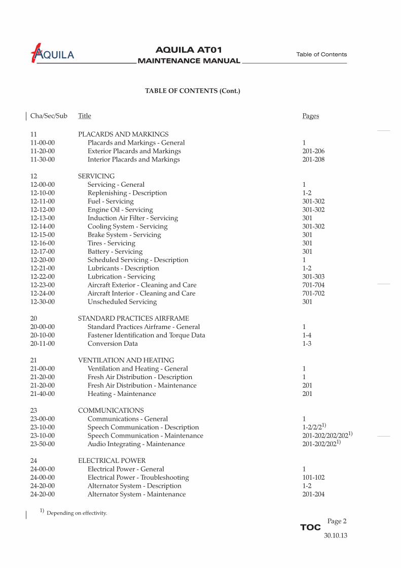
11 PLACARDS AND MARKINGS11-00-00 Placards and Markings - General 111-20-00 Exterior Placards and Markings 201-20611-30-00 Interior Placards and Markings 201-208
12 SERVICING12-00-00 Servicing - General 112-10-00 Replenishing - Description 1-212-11-00 Fuel - Servicing 301-30212-12-00 Engine Oil - Servicing 301-30212-13-00 Induction Air Filter - Servicing 30112-14-00 Cooling System - Servicing 301-30212-15-00 Brake System - Servicing 30112-16-00 Tires - Servicing 30112-17-00 Battery - Servicing 30112-20-00 Scheduled Servicing - Description 112-21-00 Lubricants - Description 1-212-22-00 Lubrication - Servicing 301-30312-23-00 Aircraft Exterior - Cleaning and Care 701-70412-24-00 Aircraft Interior - Cleaning and Care 701-70212-30-00 Unscheduled Servicing 301
20 STANDARD PRACTICES AIRFRAME20-00-00 Standard Practices Airframe - General 120-10-00 Fastener Identification and Torque Data 1-420-11-00 Conversion Data 1-3
21 VENTILATION AND HEATING21-00-00 Ventilation and Heating - General 121-20-00 Fresh Air Distribution - Description 121-20-00 Fresh Air Distribution - Maintenance 20121-40-00 Heating - Maintenance 201
23 COMMUNICATIONS23-00-00 Communications - General 123-10-00 Speech Communication - Description 1-2/2/223-10-00 Speech Communication - Maintenance 201-202/202/20223-50-00 Audio Integrating - Maintenance 201-202/202
24 ELECTRICAL POWER24-00-00 Electrical Power - General 124-00-00 Electrical Power - Troubleshooting 101-10224-20-00 Alternator System - Description 1-224-20-00 Alternator System - Maintenance 201-204
1)
1)
1)
TOCPage 2
Table of Contents
30.10.13
1) Depending on effectivity.

MAINTENANCE MANUAL
AQUILA AT01A
TABLE OF CONTENTS (Cont.)
Cha/Sec/Sub Title Pages
24-30-00 Battery System - Description 1-224-30-00 Battery System - Maintenance 201-20224-40-00 External Power - Maintenance 201-20324-60-00 Electrical Load Distribution - Description 124-61-00 Circuit Breaker - Maintenance 20124-97-00 Electrical System Wiring - Maintenance 201
25 EQUIPMENT / FURNISHINGS25-00-00 Equipment / Furnishings - General 125-10-00 Seats - Maintenance 201-20325-11-00 Restraint System - Maintenance 20125-12-00 Cabin Interior - Maintenance 201-20325-50-00 Cargo Tie Downs - Maintenance 20125-60-00 Emergency Equipment - Description 1-225-62-00 Emergency Locater Transmitter - Maintenance 201-20225-66-00 Fire Extinguisher - Maintenance 201-201/202
27 FLIGHT CONTROLS27-00-00 Flight Controls - General 127-10-00 Aileron Control System - Description 1-227-10-00 Aileron Control System - Maintenance 201-20727-20-00 Rudder Control System - Description 1-227-20-00 Rudder Control System - Maintenance 201-20527-30-00 Elevator Control System - Description 1-227-30-00 Elevator Control System - Maintenance 201-20527-31-00 Elevator Trim Control System - Description 1-227-31-00 Elevator Trim Control System - Maintenance 201-20227-50-00 Flap Control System - Description 1-227-50-00 Flap Control System - Maintenance 201-205
28 FUEL28-00-00 Fuel - General 1-228-10-00 Fuel Storage - Description 128-10-00 Fuel Storage - Maintenance 20128-20-00 Fuel Distribution - Description 128-20-00 Fuel Distribution - Maintenance 201-20628-40-00 Fuel Indicating - Description 128-40-00 Fuel Indicating - Maintenance 201-202/203
31 INDICATING / RECORDING SYSTEMS31-00 00 Indicating / Recording Systems - General 1-2/2/231-10-00 Instrument Panel - Maintenance 201-20231-30-00 Recorders - Maintenance 201-204
1)
1)
1)
TOCPage 3
Table of Contents
30.10.13
1) Depending on effectivity.

MAINTENANCE MANUAL
AQUILA AT01A
32 LANDING GEAR32-00-00 Landing Gear - General 132-10-00 Main Gear - Description 132-10-00 Main Gear - Maintenance 201-20232-20-00 Nose Gear - Description 132-20-00 Nose Gear - Maintenance 201-20332-40-00 Wheels and Brakes - Description 132-40-00 Wheels and Brakes - Maintenance 201-208
33 LIGHTS33-00-00 Lights - General 133-10-00 Interior Lights - Maintenance 201-20233-40-00 Exterior Lights - Maintenance 201-
34 NAVIGATION34-00-00 Navigation - General 134-11-00 Pitot / Static System - Description 1-234-11-00 Pitot / Static System - Maintenance 201-20434-18-00 Stall Warning System - Description 134-18-00 Stall Warning System - Maintenance 20134-20-00 Attitude and Direction - Maintenance 201-20334-25-00 Integrated Flight System -34-40-00 Independent Position Determining - Maintenance 201-201/202/20534-45-00 Collision Warning System - Maintenance 201-20434-50-00 Dependent Position Determining - Maintenance 201-202/203
51 STRUCTURES51-00-00 Structures - General 1-251-10-00 Fiberglass Laminate Structures - Maintenance 201-20351-20-00 Repair of Fiberglass Laminate Components 201-219
52 DOORS52-00-00 Doors - General 152-10-00 Canopy - Maintenance 201-20452-30-00 Baggage Door - Maintenance 201
53 FUSELAGE53-00-00 Fuselage - General 153-10-00 Fuselage Main Frame - Description 1-453-10-00 Fuselage Main Frame - Maintenance 201
203/202
Maintenance 201-204/205
53-20-00 Auxiliary Structure - Description 1
1)
1)
1)
1)
TABLE OF CONTENTS (Cont.)
Cha/Sec/Sub Title Pages
TOCPage 4
Table of Contents
30.10.13
1) Depending on effectivity.

MAINTENANCE MANUAL
AQUILA AT01A
TABLE OF CONTENTS (Cont.)
Cha/Sec/Sub Title Pages
55 STABILIZERS55-00-00 Stabilizers - General 155-10-00 Horizontal Stabilizer - Maintenance 20155-20-00 Elevator - Maintenance 201-20355-30-00 Vertical Stabilizer - Maintenance 20155-40-00 Rudder - Maintenance 201-202
57-00-00 Wings - General 157-10-00 Wing - Maintenance 201-20657-50-00 Control Surfaces - Maintenance 201-207
61 PROPELLER61-00-00 Propeller - General 161-00-00 Propeller - Troubleshooting 101-10361-10-00 Propeller Assembly - Maintenance 201-20461-20-00 Propeller Control - Maintenance 201-204/204/204
71 POWER PLANT71-00-00 Power Plant - General 171-00-01 Engine - Description 1-371-00-01 Troubleshooting - Rotax 912S 101-10471-00-01 Rotax 912S - Maintenance 201-20371-10-00 Cowling - Maintenance 201-20271-20-00 Engine Mount - Maintenance 20171-60-00 Air Induction System - Maintenance 201
74 IGNITION SYSTEM74-00-00 Ignition System - General 1-274-10-00 Ignition System - Maintenance 201-203
75 COOLING SYSTEM75-00-00 Cooling System - General 1-275-10-00 Cooling System - Maintenance 201-20275-10-01 Winterization Kit - Maintenance 201-202
76 ENGINE CONTROLS76-00-00 Engine Controls - General 176-10-00 Engine Controls - Maintenance 201-204
56 WINDOWS56-00-00 Windows - General 156-10-00 Flight Compartment Windows - Maintenance 201-203
57 WINGS
1)
TOCPage 5
Table of Contents
30.10.13
1) Depending on effectivity.

MAINTENANCE MANUAL
AQUILA AT01A
TABLE OF CONTENTS (Cont.)
Cha/Sec/Sub Title Pages
77 ENGINE INDICATING77-00-00 Engine Indicating - General 177-10-00 Power Indication - Maintenance 201-20277-20-00 Temperature Indication - Maintenance 201
78 EXHAUST78-00-00 Exhaust - General 178-10-00 Exhaust - Maintenance 201-202
79 OIL79-00-00 Oil - General 1-279-10-00 Oil Tank - Maintenance 201-20279-20-00 Oil Cooler - Maintenance 20179-30-00 Oil Temperature Measuring System - Maintenance 20179-31-00 Oil Pressure Measuring System - Maintenance 201
80 STARTING80-00-00 Starting - General 180-10-00 Starter - Maintenance 1
91 CHARTS AND DIAGRAMS91-00-00 Charts and Diagrams - General 1-24
TOCPage 6
Table of Contents
30.10.13
MAINTENANCE MANUAL
AQUILA AT01A
Revision
Number
Revision
Number
Date of
Revision
Date of
Revision
Date
Inserted
Date
InsertedBy By
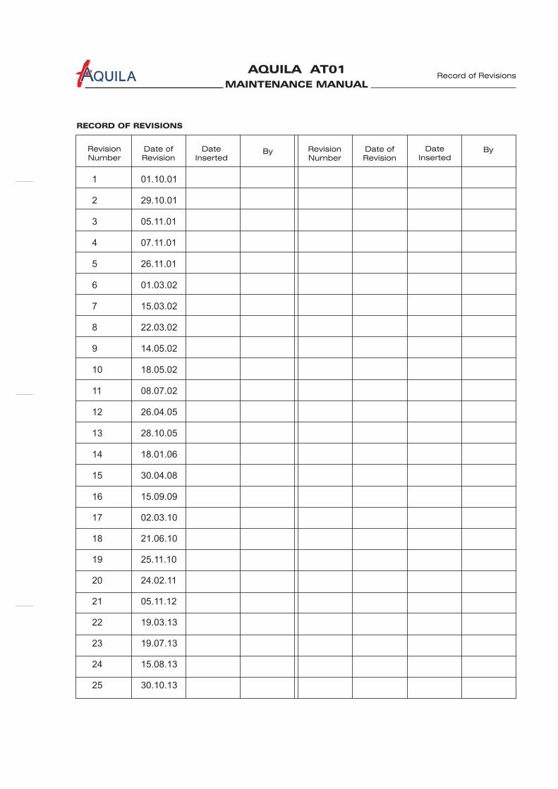
RECORD OF REVISIONS
Record of Revisions
1 01.10.01
2 29.10.01
3 05.11.01
4 07.11.01
5 26.11.01
6 01.03.02
7 15.03.02
8 22.03.02
9 14.05.02
10 18.05.02
11 08.07.02
12 26.04.05
13 28.10.05
14 18.01.06
15 30.04.08
16 15.09.09
17 02.03.10
18 21.06.10
19 25.11.10
20 24.02.11
21 05.11.12
22 19.03.13
23 19.07.13
24 15.08.13
25 30.10.13

MAINTENANCE MANUAL
AQUILA AT01A

MAINTENANCE MANUAL
AQUILA AT01A
Temp. Revision
NumberPage Date of
RevisionBy ByDate
Removed
RECORD OF TEMPORARY REVISIONS
Record of Temp. Revisions
01 05-20-00, p. 04 24.01.13 19.03.13

MAINTENANCE MANUAL
AQUILA AT01A
MAINTENANCE MANUAL
AQUILA AT01A
Revision
Number
Revision
Number
Date of
Revision
Date of
Revision
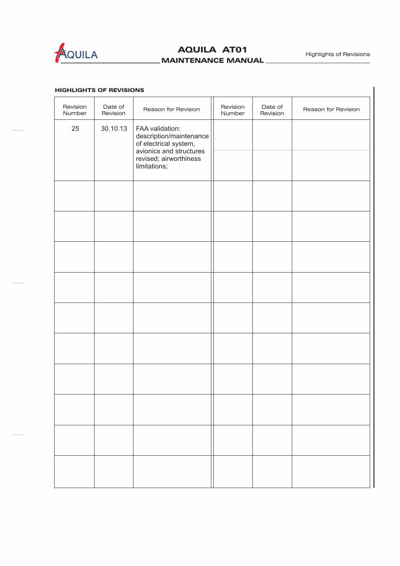
HIGHLIGHTS OF REVISIONS
Highlights of Revisions
Reason for Revision Reason for Revision
25 30.10.13 FAA validation:description/maintenanceof electrical system,avionics and structuresrevised; airworthinesslimitations;

MAINTENANCE MANUAL
AQUILA AT01A
MAINTENANCE MANUAL
AQUILA AT01A
MAINTENANCE MANUAL
AQUILA AT01A
INTRODUCTION
Introduction
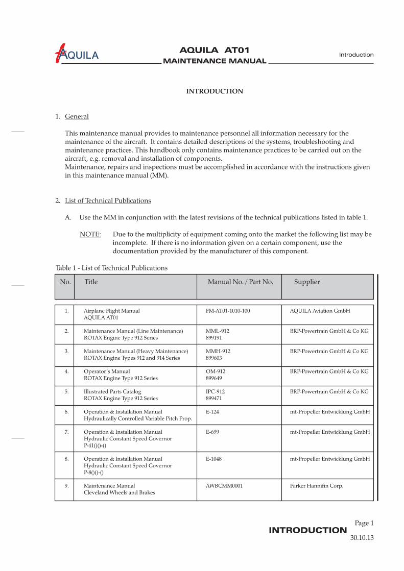
Table 1 - List of Technical Publications
30.10.13
INTRODUCTION
1.
This maintenance manual provides to necessary for themaintenance of the aircraft. It contains detailed descriptions of the systems, troubleshooting andmaintenance practices. This handbook only contains maintenance practices to be carried out on theaircraft, e.g. removal and installation of components.Maintenance, repairs and inspections must be accomplished in accordance with the instructions givenin this maintenance manual (MM).
2.
A. Use the MM in conjunction with the latest revisions of the technical publications listed in table 1.
Due to the multiplicity of equipment coming onto the market the following list may beincomplete. If there is no information given on a certain component, use thedocumentation provided by the manufacturer of this component.
General
List of Technical Publications
NOTE:
maintenance personnel all information
Page 1
1. Airplane Flight Manual FM-AT01-1010-100 AQUILA Aviation GmbHAQUILA AT01
2. Maintenance Manual (Line Maintenance) MML-912 BRP-Powertrain GmbH & Co KGROTAX Engine Type 912 Series 899191
3. Maintenance Manual (Heavy Maintenance) MMH-912 BRP-Powertrain GmbH & Co KGROTAX Engine Types 912 and 914 Series 899603
4. Operator’s Manual OM-912 BRP-Powertrain GmbH & Co KGROTAX Engine Type 912 Series 899649
5. Illustrated Parts Catalog IPC-912 BRP-Powertrain GmbH & Co KGROTAX Engine Type 912 Series 899471
6. Operation & Installation Manual E-124 mt-Propeller Entwicklung GmbHHydraulically Controlled Variable Pitch Prop.
7. Operation & Installation Manual E-699 mt-Propeller Entwicklung GmbHHydraulic Constant Speed GovernorP-41()()-()
8. Operation & Installation Manual E-1048 mt-Propeller Entwicklung GmbHHydraulic Constant Speed GovernorP-8()()-()
9. Maintenance Manual AWBCMM0001 Parker Hannifin Corp.Cleveland Wheels and Brakes
No. Title Manual No. / Part No. Supplier

MAINTENANCE MANUAL
AQUILA AT01A
INTRODUCTIONPage 2
Introduction
30.10.13
Table 1 - List of Technical Publications (Cont.)
No. Title Manual No. / Part No. Supplier
10. G500 AML STC Installation Manual 190-01102-06 Garmin International Inc.
11. Instructions for Continued Airworthiness 190-01102-00 Garmin International Inc.G500 PFD/MFD System
12. Installation Manual 900-00003-001 Aspen Avionics Inc.EFD1000 and EFD500 Software Version 2.x
13. Instructions for Continued Airworthiness 900-00012-001 Aspen Avionics Inc.EFD1000 and EFD500
14. Installation Manual 190-00149-01 Garmin International Inc.GMA 340 Audio Panel
15. Pilot’s Guide 190-00149-10 Garmin International Inc.GMA 340 Audio Panel
16. Installation Manual 190-01134-11 Garmin International Inc.GMA 350/350H
17. Pilot’s Guide 190-01134-12 Garmin International Inc.GMA 350
18. Maintenance Manual 006-15545-0002 Honeywell International Inc.Bendix/King KT 76C ATCRBC Transponder
19. Installation Manual 190-00420-04 Garmin International Inc.GTX 328 Transponder
20. Installation Manual 190-00207-02 Garmin International Inc.GTX 330 Transponder
21. Installation Manual 190-00140-02 Garmin International Inc.400 Series
22. Installation Manual 190-00356-02 Garmin International Inc.400W Series
23. Installation Manual 190-00181-02 Garmin International Inc.500 Series
24. Installation Manual 190-00357-02 Garmin International Inc.500W Series
25. Installation Manual 190-01007 Garmin International Inc.GTN 6xx/7xx AML STC
26. Installation Manual 006-10607-0000 Honeywell International Inc.Bendix/King KMD 150 MFD/GPS
27. Installation Manual 500-301 Stauff Systec GmbHFlymap L
28. Installation Manual 560-0404-03 Garmin AT Inc.Model SL30 NAV/COMM

MAINTENANCE MANUAL
AQUILA AT01A
INTRODUCTION
Page 3
Introduction
30.10.13
No. Title Manual No. / Part No. Supplier
Table 1 - List of Technical Publications (Cont.)
29. Pilot’s Guide 560-0403-01 Garmin AT Inc.SL30 NAV/COMM
30. Installation Manual 560-0956-03 Garmin AT Inc.Model SL40 VHF COMM Transceiver
31. Pilot’s Guide 560-0954-02 Garmin AT Inc.SL40 VHF COMM
32. Installation Manual / Operation Manual DOC 08038 Kannad Aviation EnquiriesKannad 406 AF Compact Ref. 0145599 Orolia SAS
33. Installation Manual 01.0200.11E Garrecht Avionik GmbHVT-01 Transponder
34. Installation Manual 02.0200.11E Garrecht Avionik GmbHVT-02 Transponder
35. Installation Manual --- FLARM Technology GmbHFLARM Collision Warning Unit
36. Maintenance Manual 5006-05335-0001 Honeywell International Inc.Bendix/King KX 125
37. Acceptable Methods, Techniques and AC 43.13-1B Federal Aviation AdministrationPractices - Aircraft Inspection and Repair (FAA)

MAINTENANCE MANUAL
AQUILA AT01A
3.
The MM has been prepared in accordance with the Air Transport Association (ATA) SpecificationNumber 100 for Manufacturer’s Technical Data.
A. Classification of Subject Matter
The MM is divided into 5 major sections. Each of these sections is sub-divided into chapters.A table of contents is provided at the beginning of each MM chapter.
(1) General Ch. 05 - 12(2) Airframe Systems Ch. 20 - 37(3) Structures Ch. 51 - 57(4) Propeller Ch. 61(5) Power Plant Ch. 71 - 80
Each chapter is identified by a separator sheet with the chapter number and the title.
B. Page Numbering System
(1) The page numbering system consists of three-element numbers separated by dashes.
The first element identifies a system:e.g. 27 Flight Controls (a chapter)
The second element identifis a subsystem in the system:
e.g. 27-30 Elevator (a section)
If the system comprises several subsystems, further sections are added:e.g. 27 - 31 Elevator Trim Control (a further section)
The last number permits the identification of the individual units in a system or subsystem.However, this number is only used when detailed description of such individual units isrequired.
Example
27 - 10 - 00
Chapter/ Section/ Subject/System Subsystem Unit(here Flight- (hereControls) Ailerons)
Structure of the Maintenance Manual
:
30.10.13
Page 4INTRODUCTION
Introduction
MAINTENANCE MANUAL
AQUILA AT01A
Page 5INTRODUCTION
Introduction
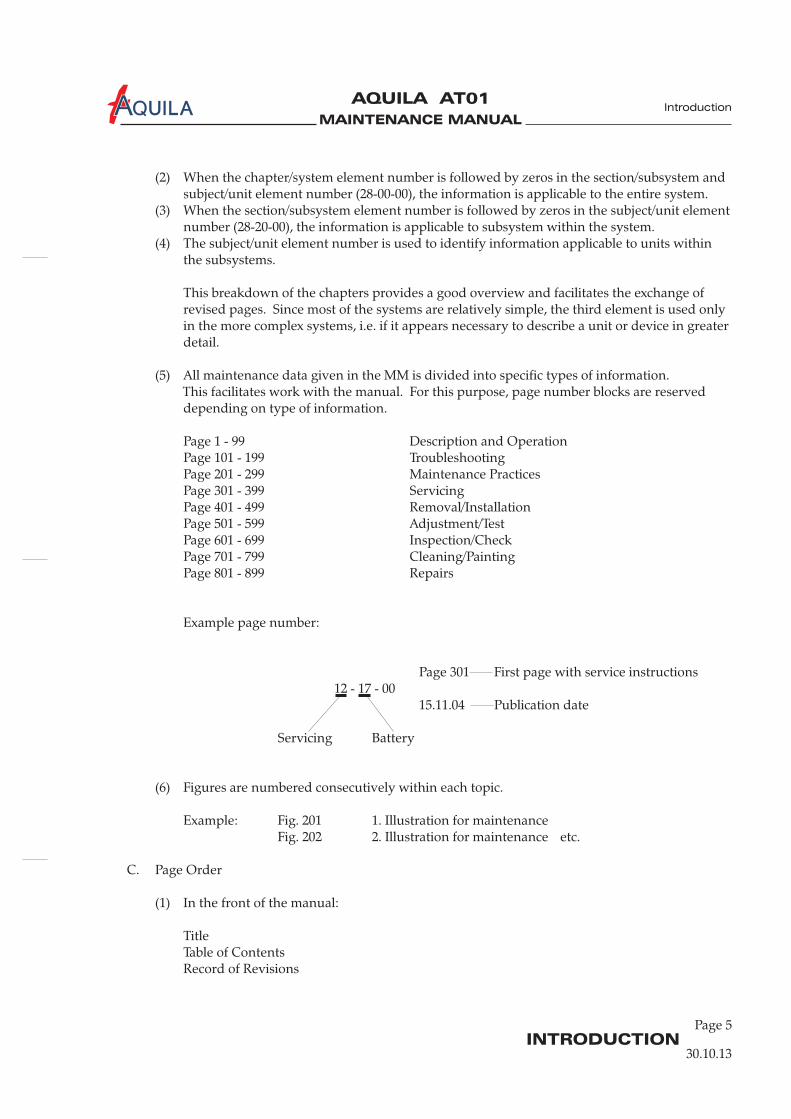
(2) When the chapter/system element number is followed by zeros in the section/subsystem andsubject/unit element number (28-00-00), the information is applicable to the entire system.
(3) When the section/subsystem element number is followed by zeros in the subject/unit elementnumber (28-20-00), the information is applicable to subsystem within the system.
(4) The subject/unit element number is used to identify information applicable to units withinthe subsystems.
This breakdown of the chapters provides a good overview and facilitates the exchange ofrevised pages. Since most of the systems are relatively simple, the third element is used onlyin the more complex systems, i.e. if it appears necessary to describe a unit or device in greaterdetail.
(5) All maintenance data given in the MM is divided into specific types of information.This facilitates work with the manual. For this purpose, page number blocks are reserveddepending on type of information.
Page 1 - 99 Description and OperationPage 101 - 199 TroubleshootingPage 201 - 299 Maintenance PracticesPage 301 - 399 ServicingPage 401 - 499 Removal/InstallationPage 501 - 599 Adjustment/TestPage 601 - 699 Inspection/CheckPage 701 - 799 Cleaning/PaintingPage 801 - 899 Repairs
Example page number:
Page 301 First page with service instructions12 - 17 - 00
15.11.04 Publication date
Servicing Battery
(6) Figures are numbered consecutively within each topic.
Example: Fig. 201 1. Illustration for maintenanceFig. 202 2. Illustration for maintenance etc.
C. Page Order
(1) In the front of the manual:
TitleTable of ContentsRecord of Revisions
30.10.13
MAINTENANCE MANUAL
AQUILA AT01A
INTRODUCTIONPage 6
Introduction
MeterCommon
MeterPlus
PSI DesiredValue (VDC)
Unit undertest
Pin 2 (blk) Pin 4 (red) 0 4.95 to 5.0 3010016,17,18
Pin 2 (blk) Pin 1 (wht) 0 1.70 to 2.10 3010016,17,18
Pin 2 (bik) Pin 3 (grn) 0 1.70 to 2.10 3010016,17,18
Pin 3 (grn) Pin 1 (wht) 0 -0.003 to +0.003 3010016,17,18
Pin 3 (grn) Pin 1 (wht) 10 0.031 to +0.034 3010016
Pin 3 (grn) Pin 1 (wht) 30 0.028 to +0.032 3010017
Pin 3 (grn) Pin 1 (wht) 60 0.028 to +0.032 3010018
77-40-00
Page 101
13.07.01
EFFECTIVITY
Aircraft equipped with VM 1000 Engine ManagementSystem
effectivity block
Effectivity BlockFigure 1
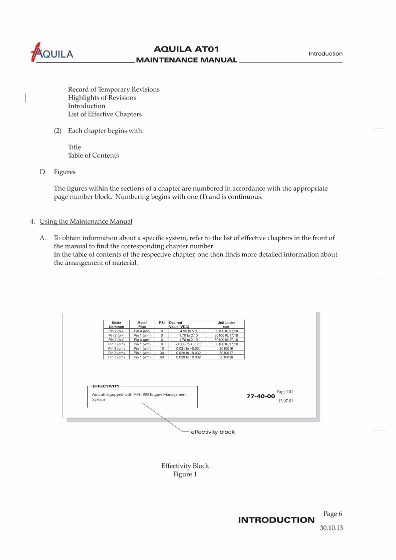
Record of Temporary RevisionsHighlights of RevisionsIntroductionList of Effective Chapters
(2) Each chapter begins with:
TitleTable of Contents
D. Figures
The figures within the sections of a chapter are numbered in accordance with the appropriatepage number block. Numbering begins with one (1) and is continuous.
4.
A. To obtain information about a specific system, refer to the list of effective chapters in the front ofthe manual to find the corresponding chapter number.In the table of contents of the respective chapter, one then finds more detailed information aboutthe arrangement of material.
Using the Maintenance Manual
30.10.13

MAINTENANCE MANUAL
AQUILA AT01A
Page 7INTRODUCTION
Introduction
B. Effectivity
This maintenance manual is "customized". It includes the following effectivity identificationsystem to show modification and/or configuration differences.
(1) The MM starts with a list of effective chapters. Each chapter is listed with date of issue orrevision.
(2) To identify the aircraft an effectivity statement (i.e. Garmin Avionics) or a six-digit numericindicator is shown in the effectivity column in the table of contents if applicable.(a) The six-digit numeric indicator begins with the last three digits of the lowest assigned
number, to indicate first effectivity, and ends with the last three digits of the highestassigned number, to indicate last effectivity, of an unbroken sequence of assignednumbers. A hyphen is shown between the numbers. Open ended effectivity isindicated by "999" in the last effectivity if applicable. For example: 023-999 indicatesaircraft 023 and subsequent.
(3) Effectivity BlockThe system provides further direct annotation of applicability on the pages. On pages notapplicable for all aircraft, an effectivity block appears at the bottom left-hand corner.Effectivity identification may be a six-digit numeric indicator (ref. to (2)(a)) or an effectivitystatement (refer to figure 1).The information on that page applies only to the aircraft noted in the effectivity block.
Pages with no effectivity block may be followed by pages with effectivity blocksand vice versa and have identical page numbers.
C. Revisions
(1) Maintenance manual revisions, caused by variety of reasons (regulation changes, technicalchanges, typographical errors, etc.), will be published regularly.
Revision notification contains a note explaining the revision along with:
- the revised manual chapters- the reason of revision- the affected airplane serial numbers
(2) Should a revision be urgently required between regular updating, a temporary revision willbe issued. The relevant pages are yellow and will usually be incorporated in the nextscheduled revision of the maintenance manual.
(3) Identifying revised material(a) Revisions and/or additions will be identified by a vertical black line (revision bar) in the
outer margin of the page opposite the text/illustration that has been changed.(b) When technical changes result in unaltered texts slipping on to a different page, a
revision bar will be placed in the outside margin, opposite the chapter/section/subject,page number and date of all affected pages, providing no other revision bar appears onthe page.
NOTE:
30.10.13

MAINTENANCE MANUAL
AQUILA AT01A
Page 8INTRODUCTION
Introduction
(4) Incorporating revisions into the manual(a) In order to keep track of revisions and to facilitate the use of the manual, a revision
always affects the entire chapter, i.e. all pages of a chapter have the same date of issue orrevision and the entire chapter is replaced during a revision.
(b) MM revisions contain an effectivity page. Chapters to be removed or inserted are listedin sequence and assigned with the respective action.Incorporation of revisions into the manual must be documented in the record ofrevisions at the front of the MM.
(c) Temporary revisions are issued as single pages and must be incorporated according tothe notes on the effectivity page delivered with the revision. They become invalid andmust be removed when the corresponding permanent revision is issued.
D. WARNINGS, CAUTIONS and NOTES
When carrying out maintenance on the airplane, general safety and maintenance rules shouldalways be observed.In addition, the MM contains warnings, cautions and notes to highlight or emphasize importantand critical instructions.
Hazard for maintenance personnel!
Hazard for systems and equipment!
Specific information
E. Abbreviations
Where it appears reasonable, abbreviations are used. They conform to recognized standards.
WARNING:
CAUTION:
NOTE:
30.10.13

MAINTENANCE MANUAL
AQUILA AT01A
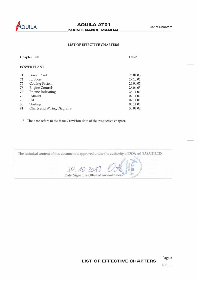
LIST OF EFFECTIVE CHAPTERS
LIST OF EFFECTIVE CHAPTERS
Chapter Title Date*
GENERAL
Introduction 30.10.1304 Airworthiness Limitations 3005 Time Limits / Maintenance Checks 15.08.1306 Dimensions and Areas 2607 Lifting & Shoring 3008 Leveling and Weighing 2709 Towing and Taxiing 0210 Parking, Mooring, Storage & Return to Service 0211 Placards and Markings 0512 Servicing 30
AIRFRAME SYSTEMS
20 Standard Practices Airframe 0521 Ventilation and Heating 0823 Communications 3024 Electrical Power 3025 Equipment and Furnishings 30.10.1327 Flight Controls 3028 Fuel 05.11.1231 Indicating/Recording Systems 3032 Landing Gear 1533 Lights 30.10.1334 Navigation 30
STRUCTURES
51 Structures 30
53 Fuselage 3055 Stabilizers 14
57 Wings 18
PROPELLER
61 Propeller 19
Table of Contents 30.10.13
.10.13
.04.05
.10.13
.09.01
.03.10
.03.10
.11.12
.10.13
.11.12
.07.02
.10.13
.10.13
.10.13
.10.13
.03.02
.10.13
.10.1352 Doors 30.10.13
.10.13
.05.0256 Windows 19.07.13
.01.06
.03.13
List of Chapters
30.10.13
Page 1
MAINTENANCE MANUAL
AQUILA AT01A
MAINTENANCE MANUAL
AQUILA AT01A
LIST OF EFFECTIVE CHAPTERS
POWER PLANT
71 Power Plant 2674 Ignition 2975 Cooling System 2676 Engine Controls 2677 Engine Indicating 2678 Exhaust 0779 Oil 0780 Starting 0591 Charts and Wiring Diagrams
* The date refers to the issue / revision date of the respective chapter.
.04.05
.10.01
.04.05
.04.05
.11.01
.11.01
.11.01
.11.0130.04.08
LIST OF EFFECTIVE CHAPTERS
Chapter Title Date*
List of Chapters
30.10.13
Page 2
The technical content of this document is approved under the authority of DOA ref. EASA.21J.025.
Date, Signature Office of Airworthiness

MAINTENANCE MANUAL
AQUILA AT01A
CHAPTER 4
AIRWORTHINESS LIMITATIONS

MAINTENANCE MANUAL
AQUILA AT01A
MAINTENANCE MANUAL
AQUILA AT01A
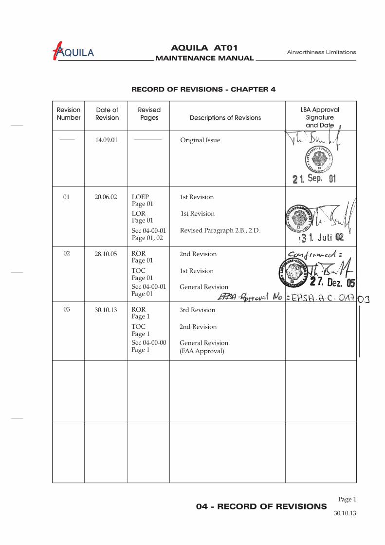
04 - RECORD OF REVISIONS
RECORD OF REVISIONS - CHAPTER 4
Airworthiness Limitations
30.10.13
Page 1
Revision
Number
Date of
Revision
Revised
Pages Descriptions of Revisions
LBA Approval
Signature
and Date
Original Issue14.09.01
01
02
20.06.02
28.10.05
Sec 04-00-01
TOC
Page 01
Page 01
Page 01
Page 01, 02
Page 01
Page 01
Revised Paragraph 2.B., 2.D.
1st Revision
General Revision
LOEP
LOR
ROR
1st Revision
1st Revision
2nd Revision
03 30.10.13
TOC
Page 1
Page 1
Page 1
2nd Revision
General Revision(FAA Approval)
ROR 3rd Revision
Sec 04-00-01
Sec 04-00-00

MAINTENANCE MANUAL
AQUILA AT01A
MAINTENANCE MANUAL
AQUILA AT01A
04 - TOC
Page 1
Airworthiness Limitations
30.10.13
TABLE OF CONTENTS
ChapterSection
AIRWORTHINESS LIMITATIONS - GENERAL ..........................................04-00-00 1IntroductionAirworthiness Limitations 04-00-00 1
Title Subject Page
04-00-00 1

MAINTENANCE MANUAL
AQUILA AT01A

MAINTENANCE MANUAL
AQUILA AT01A
04-00-00
Airworthiness Limitations
30.10.13
AIRWORTHINESS LIMITATIONS - GENERAL
1.
This chapter gives information on mandatory replacement times of structural parts andcomponents and on inspection periods for the airframe structure of the aircraft.All mandatory limitations listed have been determined by the airframe manufacturer.Compliance with the specified times and intervals is mandatory for maintaining the airworthinessof the aircraft.
2.
A. Life Time LimitThe
Introduction
Airworthiness Limitations
THE AIRWORTHINESS LIMITATIONS CHAPTER IS APPROVED BY EUROPEAN AVIATIONSAFETY AGENCY (EASA) IN ACCORDANCE WITH THE APPLICABLE CERTIFICATIONPROCEDURES AND THE TYPE CERTIFICATION BASIS.
THE AIRWORTHINESS LIMITATIONS CHAPTER IS FAA APPROVED AND SPECIFIESMAINTENANCE REQUIRED UNDER SECS. 43.16 AND 91.403 OF THE FEDERAL AVIATIONREGULATIONS UNLESS AN ALTERNATIVE PROGRAM HAS BEEN FAA APPROVED.
For possible airworthiness limitations of engine, propeller, components and vendor equipmentrefer to the applicable maintenance data as listed in the “Introduction” chapter of this manual.
airframe of the AQUILA AT01 is limited to of flight time.
An inspection program to reach an extension of replacement time will be published byAQUILA Aviation GmbH before any AQUILA AT01 reaches 6000 h.
B. Component and System ChecksThe following table lists maintenance and checks that have to be carried out at the specifiedintervals. Where an interval is given in both flight time and calendar time, the limit which isreached first must be applied.
6000 h
NOTE:
Page 1
No. Component / Maintenance Requirement Reference Interval Initials100h other
- - - - -

MAINTENANCE MANUAL
AQUILA AT01A
04-00-00Page 2
30.10.13
C. Replacement RequirementsThe aircraft components listed below are life limited and must be replaced/overhauled at a specifictime. Where an interval is given in both flight time and calendar time, the limit which is reachedfirst must be applied.
- - - -
AT01-2100-001 Fuselage (incl. vertical stabilizer and rudder)AT01-2130-001 Upper cowlingAT01-3000-001 Horizontal stabilizer (incl. elevator)AT01-4000-001 Wing (incl. flaps and ailerons)
For airplanes registered in the USA or countries where the FAA-TC has been accepted,approved coatings / shades are Du Pont PUR EV310 Performance Coating / RAL 9001 and
.Before painting the aircraft with a different coating AQUILA Aviation GmbH must be contacted.
For airplanes registered in Europe or countries where the EASA-TC has been accepted,approved shades are RAL 9001 and RAL 9016.
Chapter Component / Part Replacement Time Overhaul
P/N Component / Part
D. Outside Painting of the AirframeAll structural parts which are exposed to direct vertical sunlight and listed in the table below haveto be painted WHITE, excepting areas provided for registration marks, warnings and approveddesigns. This will prevent the temperature of the structure from becoming too high.
Du Pont PUR EV310 Performance Coating / RAL 9016
Airworthiness Limitations
MAINTENANCE MANUAL
AQUILA AT01A
CHAPTER 07
LIFTING AND SHORING

MAINTENANCE MANUAL
AQUILA AT01A

MAINTENANCE MANUAL
AQUILA AT01A
Page 107 - TOC
TABLE OF CONTENTS
ChapterSection
LIFTING AND SHORING - GENERAL.........................................................07-00-00 1Introduction 07-00-00 1General Description 07-00-00 1
JACKING.............................................................................................................07-10-00 201General 07-10-00 201Tools, Equipment and Material 07-10-00 201Jacking 07-10-00 201Hoisting 07-10-00 202
Title Subject Page
Lifting and Shoring
30.10.13

MAINTENANCE MANUAL
AQUILA AT01A

MAINTENANCE MANUAL
AQUILA AT01A
07-00-00
LIFTING AND SHORING - GENERAL
1.
A. This chapter describes procedures used to jack the aircraft. The equipment required to jack theaircraft and the procedures to be followed are described.
2.
In the following, a brief description and intended purpose of each section of this chapter is given.
A. Section 7-00-00 - Lifting and Shoring - General. This section provides a general overview ofcontent and purpose of the chapter.
B. Section 7-10-00 - Jacking. This section contains procedures, supplementary information andrequired equipment for jacking the aircraft.
Introduction
General Description
Lifting and Shoring
30.10.13
Page 1

MAINTENANCE MANUAL
AQUILA AT01A
MAINTENANCE MANUAL
AQUILA AT01A
07-10-00Page 201
30.10.13
JACKING
1.
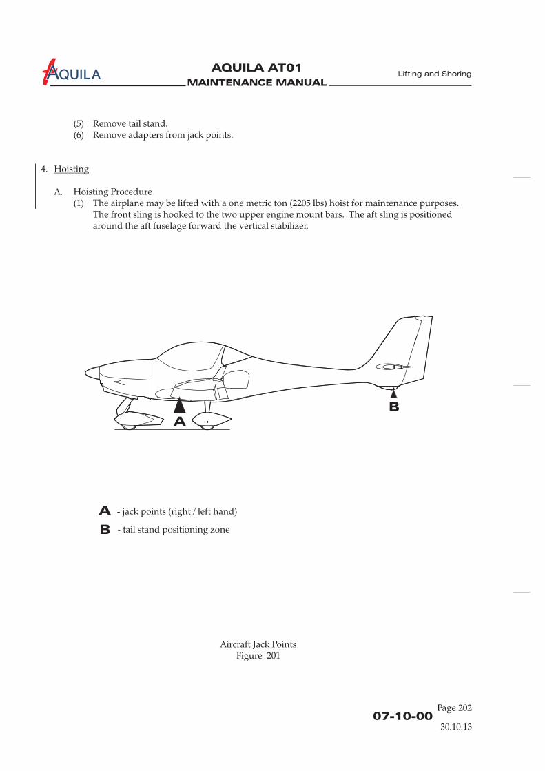
A. The aircraft is jacked at two points and supported at the tail. The jack points are located at thebottom of the fuselage root ribs (see figure 201). Special adapters must be installed prior to jacking.
B. If necessary, the aircraft may be lifted on a hoist.
2.
Quantity Equipment Parts No. Manufacturer
3.A 2 Jack - commercially available3.A 2 Adapter3.A 1 Tail stand -
3.
A. Jacking the Aircraft
DO NOT JACK THE AIRCRAFT IN THE OPEN IF WIND VELOCITY EXCEEDS 6KNOTS.
(1) In the open, postion the aircraft with thenose into the wind.
: ONLY USE JACKS IN COMBINATION WITH ADAPTERS DELIVERED BY
(2) Install adapters to jack points (marked red).(3) Place jacks at the correct positions under the fuselage (see figure 201) and extend to engage
with the jacking points.(4) Remove wheel chocks.(5) Place the tail stand with adapter under the lower fin and extend to engage with the lower fin
skid plate. Secure tail stand lock.(6) Raise jacks simultaneously, keeping the aircraft as level as possible.(7) Secure jack locks.(8) Place the wing trestles in position under each wing (zone 530 /630).
B. Lowering the Aircraft(1) Remove the wing trestles from under the wings.(2) Check that the areas immediately under and over the aircraft are clear.(3) Slowly lower the jacks simultaneously,(4) When the main tires are resting on the ground, lower the jacks completely and remove them.
General
Tools, Equipment and Material
Jacking
CAUTION:
CAUTION
AQUILA Aviation GmbHcommercially available
3.A 2 Wing trestles - commercially available
Position the aircraft on a hard, flat, level surface.
AQUILA.
keeping the aircraft as level as possible.
Lifting and Shoring
MAINTENANCE MANUAL
AQUILA AT01A
07-10-00Page 202
Aircraft Jack PointsFigure 201
A
A
B
B
- jack points (right / left hand)
- tail stand positioning zone
(5) Remove tail stand.(6) Remove adapters from jack points.
4.
A. Hoisting Procedure(1) The airplane may be lifted with a one metric ton (2205 lbs) hoist for maintenance purposes.
The front sling is hooked to the two upper engine mount bars. The aft sling is positionedaround the aft fuselage forward the vertical stabilizer.
Hoisting
Lifting and Shoring
30.10.13

MAINTENANCE MANUAL
AQUILA AT01A
CHAPTER 12
SERVICING

MAINTENANCE MANUAL
AQUILA AT01A

MAINTENANCE MANUAL
AQUILA AT01A
Page 112 - TOC
TABLE OF CONTENTS
ChapterSection
SERVICING - GENERAL..................................................................................12-00-00 1Introduction 12-00-00 1General Description 12-00-00 1
REPLENISHING - DESCRIPTION.................................................................12-10-00 1General 12-10-00 1Fuel 12-10-00 1Engine Oil 12-10-00 2Hydraulic Fluid 12-10-00 2
FUEL - SERVICING...........................................................................................12-11-00 301General 12-11-00 301Safety and Maintenance Precautions 12-11-00 301Fueling and Defueling 12-11-00 302
ENGINE OIL - SERVICING.............................................................................12-12-00 301General 12-12-00 301Checking Engine Oil 12-12-00 301Oil Change Intervals 12-12-00 301Oil Changing 12-12-00 302
INDUCTION AIR FILTER - SERVICING ......................................................12-13-00 301General 12-13-00 301Air Filter Changing 12-13-00 301Air Filter Cleaning 12-13-00 301
COOLING SYSTEM - SERVICING ................................................................12-14-00 301General 12-14-00 301Adding Coolant 12-14-00 301Renewal of the Coolant 12-14-00 302
BRAKE SYSTEM - SERVICING.......................................................................12-15-00 301General 12-15-00 301Hydraulic Fluid Replenishing 12-15-00 301
TIRES - SERVICING..........................................................................................12-16-00 301General 12-16-00 301Tire Servicing 12-16-00 301
Title Subject Page
Servicing
30.10.13
MAINTENANCE MANUAL
AQUILA AT01A
12 - TOCPage 2
30.10.13
BATTERY - SERVICING ...................................................................................12-17-00 301General 12-17-00 301Battery Servicing 12-17-00 301
SCHEDULED SERVICING - DESCRIPTION ...............................................12-20-00 1General 12-20-00 1
LUBRICANTS - DESCRIPTION......................................................................12-21-00 1General 12-21-00 1Service Notes 12-21-00 1Definition of „As Needed“ 12-21-00 1Recommended Lubricants 12-21-00 1
LUBRICATION - SERVICING .........................................................................12-22-00 301General 12-22-00 301Lubrication Chart 12-22-00 301
AIRCRAFT EXTERIOR - CLEANING AND CARE ......................................12-23-00 701General 12-23-00 701Safety Precautions 12-23-00 701Cleaning and Care of the Canopy 12-23-00 701Cleaning and Care of the Aircraft Exterior Surfaces 12-23-00 702
Cleaning the Engine 12-23-00 703Cleaning and Care of the Propeller 12-23-00 704Cleaning the Landing Gear 12-23-00 704
AIRCRAFT INTERIOR - CLEANING AND CARE.......................................12-24-00 701General 12-24-00 701Aircraft Interior Cleaning 12-24-00 701Cleaning the Instrument Panel 12-24-00 701Cleaning the Cabin Floor 12-24-00 701Cleaning the Seats 12-24-00 701
UNSCHEDULED SERVICING........................................................................12-30-00 301General 12-30-00 301Removing Snow and Ice 12-30-00 301
Cleaning and Care of Navigation / Position / Anti-Collision Lights 12-23-00 702
Servicing
TABLE OF CONTENTS (Cont.)
ChapterSection
Title Subject Page

MAINTENANCE MANUAL
AQUILA AT01A
12-00-0030.10.13
SERVICING - GENERAL
1.
A. This chapter gives information on the replenishment of fluids and the lubrication of components.The chapter also contains instructions required to carry out scheduled servicing.
2.
The chapter is designed to help authorized personnel to correctly service the aircraft.Below a brief description and intended purpose of each section of this chapter is given.
A. Section 12-00-00 (Servicing - General) provides a general overview of the content and purpose ofthe chapter.
B. The subsequent sections are divided into 3 groups.(1) Replenishment Fluids
Provides information to correctly perform the necessary servicing during daily aircraftoperation. This group begins with section 12-10-00 (Replenishing - Description). The sectionincludes approved fluids specifications and information about tank and reservoir capacities.
(2) Scheduled ServicingProvides information to correctly perform periodic servicing, such as lubricating componentsor cleaning the aircraft. This group begins with section 12-20-00 (Scheduled Servicing -Description).
(3) Unscheduled ServicingProvides information to correctly perform servicing, which is carried out at irregularintervals, for example removing ice and snow.
Introduction
General Description
Servicing
Page 1

MAINTENANCE MANUAL
AQUILA AT01A

MAINTENANCE MANUAL
AQUILA AT01A
12-10-00
REPLENISHING - DESCRIPTION
1.
A. This chapter provides information about fluids which must be replenished during operation.
2.
A. Fuel Capacity
Liters U.S. Gallons
Total capacity 120,0 31.7
Usable fuel 109,6 29.0
Unusable fuel 10,4 2.7
B. Fuel SpecificationThe following fuel is approved for use in the AQUILA AT01. The minimum RON should be 95.
EN 228 Super (Premium)EN 228 Super plus (Premium plus)AVGAS 100 LL (Grade ASTM-D910, blue color)AVGAS UL 91 (Grade ASTM-D7547)
For fuel specifications set down by the FAA, refer to standard spec. for automotivespark-ignition engine fuel ASTM D 4814.
There is a risk of vapor formation if winter fuel is used for summer operation.
Due to the higher lead content in AVGAS, wear of the valve sets and deposits incombustion chamber and lead sediments in the lubrication system will increase. It is,therefore, recommended to use AVGAS only if problems with vapor lock areexperienced or if the other fuel types are not available.
General
Fuel
NOTES:
ONLY USE FUEL SUITABLE FOR THE RESPECTIVE CLIMATIC ZONE.WARNING:
Servicing
30.10.13
Page 1

MAINTENANCE MANUAL
AQUILA AT01A
12-10-00
3.
A. Engine Oil Capacity
Liters U.S. Quarts
Engine oil capacity 3,0 3.17
Initial filling 3,5 3.70
Minimum 2,0 2.11
B. Oil Specification
DO NOT USE AVIATION GRADE ENGINE OIL.
IF MORE THAN 30% OF OPERATION HOURS HAVE BEEN FLOWN WITHLEADED FUEL (E.G. AVGAS 100LL), AN OIL CHANGE SHOULD BEUNDERTAKEN EVERY 50 H (REFER TO ROTAX SERVICEINFORMATION SI-912-016).
(1) Only use oil with the API classification “SF” or “SG”.(2) Due to the high stresses in the reduction gears, oils with gear additives such as high
performance motor cycle oils must be used.(3) Because of the incorporated friction clutch, oils with friction modifier additives are unsuitable
as this could result in a slipping clutch during normal operation.(4) Heavy duty 4-stroke motor cycle oils meet all requirements. These oils are normally not
mineral oils but semi- or full synthetic oils.(5) Diesel engine oils are generally unsuitable due to temperature properties and additives
which favor clutch slipping.
For more information on the necessary lubricants, refer to Rotax Aircraft EnginesService Information .
C. Recommended Oil Viscosity for various Air Temperatures:
4.
A. Hydraulic fluid fulfilling the MIL-H-5606 specification only should be used.
Engine Oil
CAUTION:
NOTE:
Hydraulic Fluid
AIRCRAFT ENGINES
SI-912-016
Mean ambienttemperature Multi grade oils
-5°C (23 °F) to 40°C (104 °F) SAE 20W-50 SAE 20W-40-16°C (3.2 °F) to 40°C (104 °F) SAE 15W-50 SAE 15W-40-26°C (-14.8 °F) to 40°C (104 °F) SAE 10W-50-30°C (-22 °F) to 40°C (104 °F) SAE 5W-50 SAE 5W-40
Servicing
30.10.13
Page 2

MAINTENANCE MANUAL
AQUILA AT01A
12-11-00
Page 301
FUEL - SERVICING
1.
A. Fuel Tanks(1) The aircraft is equipped with two integral wing fuel tanks.
The fuel tanks are located inside each wing between the front and rear spars. Each fuel tankhas a filler cap on the top wing surface.
B. Drain System(1) The fuel system is equipped with drain valves to allow examination for contamination, water
and for de-fueling.Each wing fuel tank has a drain valve at the bottom, inboard rear corner. A further drainvalve is located at the lowest point of the fuel system; at the base of the electrical fuel pump.The pump is attached to the lower right firewall in the engine compartment. The drain isaccessible from outside the nose section.The center of the fuel drains can be pushed inward with the fuel sampler to inspect for waterand contamination.
Chapter 28 (Fuel) contains more detailed information about the fuel system.
2.
A. Safety Precautions
SERVICEABLE FIRE FIGHTING EQUIPMENT MUST BE AVAILABLE.
AIRCRAFT AND FILLING FITTINGS MUST BE GROUNDED.
ALL ELECTRICAL EQUIPMENT IN THE AIRCRAFT SHOULD BE TURNEDOFF. THE ALT / BAT SWITCH SHOULD BE IN THE OFF POSITION ANDTHE IGNITION KEY REMOVED FROM THE AIRCRAFT.
NO SMOKING!
(1) Before beginning maintenance, a serviceable fire extinguisher (at least foam extinguisher)must be positioned within easy access.
(2) Do not wear clothing that has a tendency to generate static electricity (i.e. synthetic fabrics).(3) No metal tabs on footwear.(4) Carry out fuel system servicing procedures only in a designated fuel loading/unloading area.(5) Ground equipment near the aircraft must be turned off.(6) While filling do not turn on any electrical device.(7) Make sure that the aircraft and filling fittings are properly grounded:
(a) First ground the aircraft;(b) If a mobile filling device is being used, ground the filling device (same potential as
aircraft);(c) Ground the mobile filling device with the aircraft.
General
NOTE:
Safety and Maintenance Precautions
WARNING: DURINGALL FUEL SYSTEM SERVICING PROCEDURES
" "
Servicing
30.10.13

MAINTENANCE MANUAL
AQUILA AT01A
12-11-00Page 302
B. Maintenance Precautions(1) Use designated equipment for fuel loading / unloading to prevent contamination.(2) Only use approved anti-icing additive.(3) Blend fuel in accordance with prescribed procedures.(4) Document all fuel blending.
3.
A. Fueling(1) Move aircraft to a designated fuel loading / fuel unloading area.(2) Make sure that the ALT / BAT switch is in the OFF position.(3) Ground aircraft and filling device as described above.(4) Position a fire extinguisher near to the fuel tank to be serviced.(5) Remove fuel filler cap and fill fuel tank to desired level.(6) Remove fuel service nozzle and install fuel cap.(7) Move fire extinguisher and the fuel service nozzle to the other tank to be filled.
(10) Check correct lock of both fuel filler caps. Remove excess fuel from the wing area using acloth.
(11) Remove ground cables.(12) Compare reading of fueled amount on filling device with readings on the fuel indicators in
the aircraft.
B. Defueling(1) Move aircraft to a designated fuel loading / fuel unloading area.(2) Make sure you have enough fuel collectors.(3) Make sure that the ALT / BAT switch is in OFF position.(4) Ground aircraft and filling device as described above.(5)(6) Remove fuel cap and remove as much fuel as possible using a defueling nozzle.
(8)
(11) Drain remaining fuel from each wing fuel tank.(12) Drain remaining fuel from the drain valve located at the base of the electrical fuel pump with
the fuel selector valve in the position LEFT and then in the position RIGHT.(13) Make sure all drain valves are closed securely.(14)
Fueling and Defueling
(8) Remove fuel filler cap and fill fuel tank to desired level.(9) Remove fuel service nozzle and install fuel cap.
Position a fire extinguisher near to the fuel tank to be defueled.
(7) Install fuel cap.Move fire extinguisher and the defueling nozzle to the other tank to be defueled.
(9) Remove fuel cap and remove as much fuel as possible using a defueling nozzle.(10) Install fuel cap.
Remove ground cables.
Servicing
30.10.13

MAINTENANCE MANUAL
AQUILA AT01A
12-12-00
Page 301
ENGINE OIL - SERVICING
1.
A. This chapter provides information for checking and changing engine oil.
B. The oil filler cap of the oil tank is located on the right (starboard) side of the engine behindcylinder no. 3. It is accessible by opening the oil access plate on the upper cowling. The oil fillercap has a dipstick with min - max markings to check oil level.
2.
A. Oil Checking Procedure
AVOID SKIN CONTACT WITH ENGINE OIL. USED OIL IN PARTICULARCONTAINS MATERIALS DETRIMENTAL TO HEALTH.
(1) Turn the propeller several times by hand to transfer all the oil from the engine to the tank.
The process is completed when air flows back to the oil tank. This flow of air can beperceived as gurgling sound when the cover of the tank is removed.
(2) Open oil access plate on upper right cowling.(3) Remove oil filler cap and withdraw dipstick.(4) Wipe oil dipstick dry with a cloth.(5) Reinsert dipstick.(6) Withdraw dipstick and read oil level on dipstick.(7) If necessary, refill engine oil with correct grade and viscosity (refer to 12-10-00).
For normal engine operation maintain the oil level between the two marks as anexcessive oil level will allow oil to escape via the venting line.For longer flights replenish oil to max. mark to warrant more oil reserve.
(8) Reinsert oil dipstick, close filler cap, check for proper seating.(9) Close oil access plate.
3.
FOR ENGINE OPERATION WITH AVGAS; OIL SHOULD BE CHANGED EVERY50 HOURS (REFER TO ROTAX AIRCRAFT ENGINES SI-912-016).
General
Checking Engine Oil
WARNING:
NOTE:
NOTE:
Oil Change Intervals
CAUTION:
WARNING:
CAUTION:
BEFORE ROTATING THE PROPELLER BY HAND, ENSURE IGNITION SWITCHIS OFF, MIXTURE CONTROL IS IN THE IDLE CUT-OFF POSITION, AND THETHROTTLE IS CLOSED.
DO NOT ROTATE THE PROPELLER CLOCKWISE.
Servicing
30.10.13

MAINTENANCE MANUAL
AQUILA AT01A
12-12-00Page 302
CAUTION:
Oil Changing
WARNING:
WARNING:
UNDER SEVERE OPERATING CONDITIONS, THE FREQUENCY OF OILCHANGES MUST BE INCREASED REGARDLESS OF THE TYPE OF FUEL USED(MOGAS OR AVGAS).
A. Oil Change Intervals(1) Under normal operating conditions, oil must be changed every 100 hours.(2) For oil specifications, refer to 12-10-00 and to ROTAX Aircraft Engines SI-912-016. The
4.
A. Oil Changing Procedure(1) Run engine until operating temperature is reached.(2) Shut down engine.
HOT ENGINE COMPONENTS MAY CAUSE SKIN BURNS!
(3) Remove engine cowling (refer to 71-10-00).(4) Cut safety wire on drain screw at oil tank base. Remove drain screw.(5) Drain oil and dispose of it as per environmental regulations.(6) Remove oil filter from engine.(7) Lubricate mating sealing ring of new oil filter with engine oil.(8) Install new oil filter. Screw on new oil filter by hand.(9) Cut oil filter out of its casing (without producing any metal chips) and inspect filter material.(10) Renew gasket ring of drain screw on oil tank. Fit drain screw and tighten
to 25 Nm (220 in.lbs). Secure drain screw with safety wire.(11) Refill oil tank with approx. 3 liters (3.17 quarts) of oil. For oil specification, refer to 12-10-00
and to(12) Reinsert oil dipstick, close filler cap, check for proper seating.(13) Run engine until normal operating temperature is reached. Shut down engine.
HOT ENGINE COMPONENTS MAY CAUSE SKIN BURNS!
(14) Check oil system for leaks.(15) Tighten oil filter again by hand.(16) Reinstall cowling.(17) Document oil change as prescribed.
ROTAX Aircraft Engines SI-912-016 contains further operating information for ROTAXengines.
ROTAX Aircraft Engines SI-912-016.
Servicing
30.10.13

MAINTENANCE MANUAL
AQUILA AT01A
12-13-00
Page 301
INDUCTION AIR FILTER - SERVICING
1.
A. The air filter in the air induction system keeps dust and dirt particles from entering the system.It is located in the air filter box on the left inside of lower cowling.To increase its effectiveness, the filter element should be treated with filter oil.
B. The condition of the air filter element will be determined primarily by engine operatingconditions. Therefore, it should be regularly inspected, cleaned and replaced, if necessary, at leastevery 100 hours or once a year, whichever comes first.
2.
A. Air Filter Changing Procedure(1) Remove upper cowling (refer to 71-10-00).(2) Remove the cover of the air filter box.(3) Remove air filter element and replace by a new one.(4) Install(5) Install upper cowling (refer to 71-10-00).
3.
A. Cleaning Procedures(1) Remove air filter element as described above.(2) Inspect air filter element for damage. If necessary renew filter element.
NEVER USE GASOLINE, STEAM, CAUSTIC LIQUIDS, DETERGENTS OR HIGHPRESSURE CLEANING.
(3) Lightly tap and brush off surface dirt.(4) Spray filter cleaner on to entire element and let it soak for approx. 10 min.
DO NOT DRY OVER NAKED FLAME OR WITH HOT AIR GUN. EXCESSIVE HEATWILL SHRINK THE PORES OF THE FILTER MATERIAL RESTRICTING ENGINEAIR FLOW.
(5) Rinse filter element with water from the inside out and let it dry naturally.
(6) After cleaning, lubricate filter element evenly with filter oil spray or filter oil according to themanufacturer ’s instructions.
(7) Ensure air filter box is clean and free of debris.(8) Install air filter as described above, pay attention to correct fit.
General
Air Filter Changing
Air Filter Cleaning
CAUTION:
WARNING:
the cover of the air filter box.
NEVER USE GEAR OIL, DIESEL OIL OR MOTOR OIL AS THEY ATTRACT WATER.CAUTION:
Servicing
30.10.13

MAINTENANCE MANUAL
AQUILA AT01A
12-13-00Page 302
12.04.00
MAINTENANCE MANUAL
AQUILA AT01A
12-14-00
Page 301
COOLING SYSTEM - SERVICING
1.
A. The cooling system of the ROTAX 912 is designed for liquid cooling of the cylinder heads and ramair cooling of the cylinders. The cooling system of the cylinder heads is a closed circuit with anexpansion tank. For a more detailed description and related maintenance procedures of thecooling system, refer to 75-20-00.
B. Coolant(1) Waterless coolant based on propylene glycol such as EVANS NPG+C. Refer to the ROTAX
Service Instruction SI-912-016, latest revision, .The maximum coolant quantity is 2,5 liters (2.6 U.S. quarts).
WATER OR COOLANT CONTAINING WATER MUST NEVER BE ADDED TOTHE COOLING SYSTEM! THE MAX. WATER CONTENT MUST NOT EXCEED3,6%; IT CAN BE TESTED USING A BRIX REFRACTOMETER. ANY WATERPRESENT IN THE COOLING SYSTEM IS SEPARATED OUT AS VAPOR. THISCAN CAUSE THE COOLING SYSTEM TO FAIL DUE TO INSUFFICIENTCOOLANT QUANTITY.
USE COOLANT IN ACCORDANCE WITH MANUFACTURER SINSTRUCTIONS.
2.
A. Prior to adding coolant, the reason for the loss of the liquid must be investigated and corrected.
B. Servicing procedures(1) Remove engine cowling (refer to 71-10-00).(2) When engine is cold, open pressure cap of the expansion tank and fill up the expansion tank
completely.(3) Run engine to operating temperature and allow engine to cool down before checking coolant
level . Replenish as necessary.(4) Close pressure cap, check the condition of the rubber sealing rings.(5) Install engine cowling (refer to 71-10-00).
General
CAUTION:
Adding Coolant
WARNING:
NOTE:
NEVER OPEN PRESSURE CAP OR RADIATOR CAP WHEN THE COOLING SYSTEMIS HOT. FOR SAFETY REASONS, COVER CAP WITH A CLOTH AND OPENSLOWLY. SUDDEN OPENING OF THE CAP COULD PROVOKE THE EXIT OFBOILING COOLANT AND RESULT IN SEVERE SCALDING.
for further information on suitable coolants
'
If EVANS NPG+C is not available locally for servicing the cooling system, aconventional coolant based on pure 100% ethylene glycol can be usedtemporarily. However, the coolant must be replaced again with EVANS NPG+Cwithin the next 15 days. Only add 100% pure ethylene glycol!
again
Servicing
30.10.13
MAINTENANCE MANUAL
AQUILA AT01A
12-14-00Page 302
3.
A. Servicing procedures(1) Open the radiator cap, remove the bottom attachment screw (with sealing ring) of the water
pump and drain the coolant.(2) Install attachment screw (stainless steel) along with a new sealing ring. Tighten to 10 Nm
(90 in.lbs).(3) Refill coolant into expansion tank (highest point of the cooling system). Install radiator cap.(4) Run engine to operating temperature and allow engine to cool down before checking coolant
level. Replenish as necessary.
Renewal of the Coolant
Servicing
30.10.13
MAINTENANCE MANUAL
AQUILA AT01A
12-15-00
Page 301
BRAKE SYSTEM - SERVICING
1.
A. Ground service for the brake system is limited to the replenishment of brake fluid. The brakefluid reservoir is located at the upper left firewall in the engine compartment.
2.
A. Hydraulic Fluid Replenishing
ONLY USE HYDRAULIC FLUID WHICH CONFORMS TO MIL-H-5606SPECIFICATION.
(1) Remove upper cowling (refer to 71-10-00).(2) Remove filler plug from hydraulic fluid reservoir.
REMOVE EXCESSIVE HYDRAULIC FLUID IMMEDIATELY FROM PAINTSURFACES TO PREVENT CHEMICAL ATTACK.
(3) Refill hydraulic fluid.(4) Install filler plug.(5) Install upper cowling (refer to 71-10-00).
General
Hydraulic Fluid
CAUTION:
CAUTION:
Replenishing
Servicing
30.10.13

MAINTENANCE MANUAL
AQUILA AT01A
MAINTENANCE MANUAL
AQUILA AT01A
12-16-00
Page 301
TIRES - SERVICING
1.
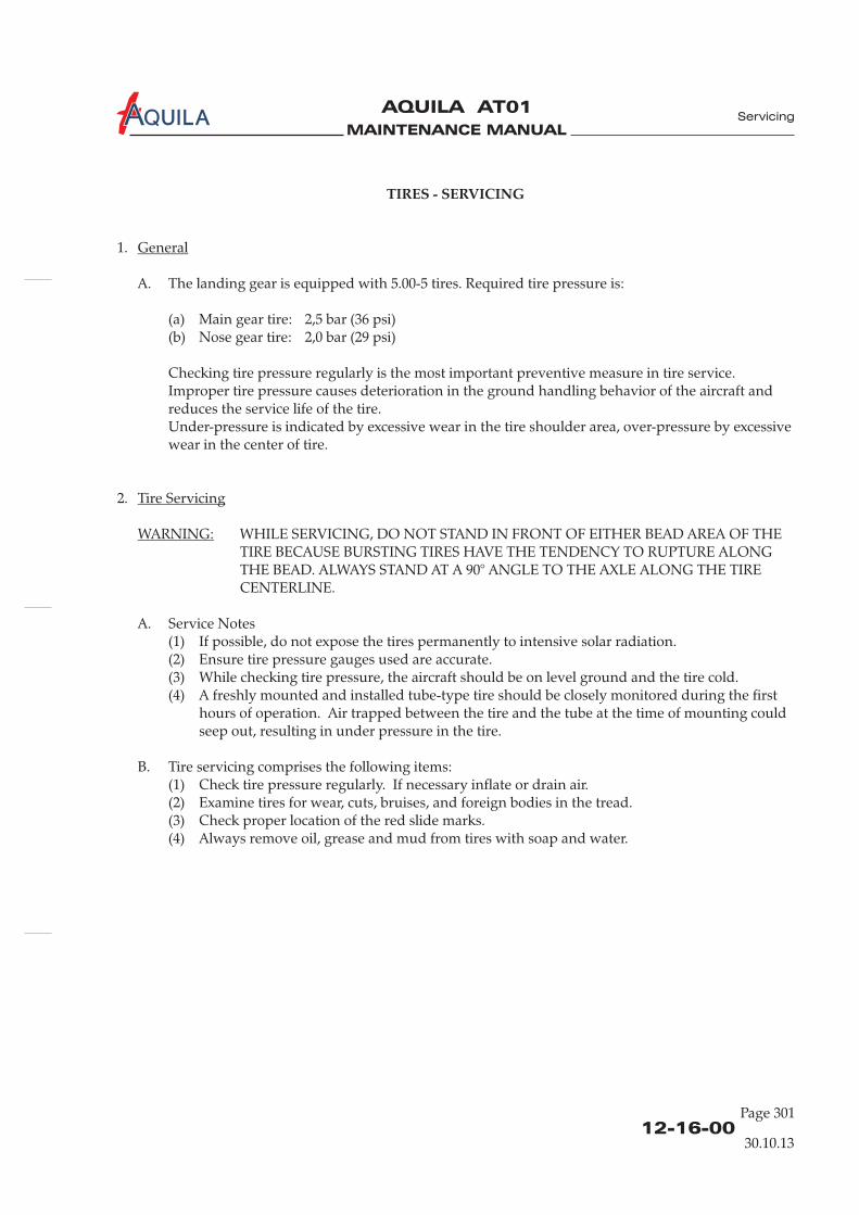
A. The landing gear is equipped with 5.00-5 tires. Required tire pressure is:
(a) Main gear tire: 2,5 bar (36 psi)(b) Nose gear tire: 2,0 bar (29 psi)
Checking tire pressure regularly is the most important preventive measure in tire service.Improper tire pressure causes deterioration in the ground handling behavior of the aircraft andreduces the service life of the tire.Under-pressure is indicated by excessive wear in the tire shoulder area, over-pressure by excessivewear in the center of tire.
2.
WHILE SERVICING, DO NOT STAND IN FRONT OF EITHER BEAD AREA OF THETIRE BECAUSE BURSTING TIRES HAVE THE TENDENCY TO RUPTURE ALONGTHE BEAD. ALWAYS STAND AT A 90° ANGLE TO THE AXLE ALONG THE TIRECENTERLINE.
A. Service Notes(1) If possible, do not expose the tires permanently to intensive solar radiation.(2) Ensure tire pressure gauges used are accurate.(3) While checking tire pressure, the aircraft should be on level ground and the tire cold.(4) A freshly mounted and installed tube-type tire should be closely monitored during the first
hours of operation. Air trapped between the tire and the tube at the time of mounting couldseep out, resulting in under pressure in the tire.
B. Tire servicing comprises the following items:(1) Check tire pressure regularly. If necessary inflate or drain air.(2) Examine tires for wear, cuts, bruises, and foreign bodies in the tread.(3) Check proper location of the red slide marks.(4) Always remove oil, grease and mud from tires with soap and water.
General
Tire Servicing
WARNING:
Servicing
30.10.13

MAINTENANCE MANUAL
AQUILA AT01A

MAINTENANCE MANUAL
AQUILA AT01A
12-17-00
Page 301
BATTERY - SERVICING
1.
A. The battery should be serviced every 100 hours. In the case of heavy-duty operation or operationin cold regions, service intervals should be shorter.
B. For procedures on how to remove and install the battery, refer to 24-30-00.
2.
The battery should be serviced only after it has been removed from the aircraft.
A. Battery servicing involves the following:(1) Check battery and battery tray for any corrosion and dirt. Clean with clear water and dry.(2) Check electrolyte level. Maintain the level approx. 10mm (0.4 in.) over the lead plates. If
necessary refill with distilled water.
TO MAINTAIN ELECTROLYTE LEVEL USE DISTILLED WATER ONLY.
(3) Check battery charging using a battery tester. Recharge battery if required.(4) Clean and grease battery terminals (refer to 12-22-00).(5) If existent, test ventilation tube for condition and obstructions.
General
Battery Servicing
NOTE:
CAUTION:
Servicing
30.10.13

MAINTENANCE MANUAL
AQUILA AT01A

MAINTENANCE MANUAL
AQUILA AT01A
12-20-00
SCHEDULED SERVICING - DESCRIPTION
1.
A. This section provides instructions necessary to carry out scheduled servicing, such as the periodiclubrication of aircraft components; external and internal cleaning. Service intervals are alsoprovided. This section does not include lubrication procedures required to complete maintenancemeasures.
General
Servicing
30.10.13
Page 1

MAINTENANCE MANUAL
AQUILA AT01A

MAINTENANCE MANUAL
AQUILA AT01A
12-21-00
LUBRICANTS - DESCRIPTION
Abbreviation Specification Description
1.
A. This section assists with the selection of proper lubricants used to maintain the aircraft.To ensure a long service life of the lubricated components, it is recommended to always pureand authorized lubricants.
2.
A. Use of the lubricants(1) Cleanliness is essential to good lubrication. Lubricants and required equipment must be kept
clean.(2) Store the lubricants in a secure place and in accordance with the manufacturer's
specifications.(3) Wipe grease fittings and areas to be lubricated with clean dry cloths before lubricating.(4) When lubricating bearings which are vented, force grease into fitting until old grease is
expelled. Remove old grease.(5) Control cables should not be lubricated, unless to prevent corrosion.
3.
A. In the following sections, time requirements for lubrication are shown either by a specific timeinterval or by „as needed“. The latter means that no interval is determined for this item. Themechanic decides when lubrication is required.
B. If one or several of the following conditions occurs simultaneously, the component must belubricated:(1) The old lubricant has been removed.(2) Dirt or wear residue are visible near the movement contact area.(3) While moving squeaks, grinding or other abnormal sounds are audible.(4) During movement by the hand, jerky or restricted movement occurs throughout portions of
travel range.
4.
A. Categories of lubricants, their specifications and typical areas of application are provided below.
GR MIL-PRF-81322 Grease, wide temperature range
GH MIL-PRF-23827 Grease, aircraft and instrument,Gear and actuator screw
General
Service Notes
Definition of "As Needed"
Recommended Lubricants
use
Servicing
30.10.13
Page 1
MAINTENANCE MANUAL
AQUILA AT01A
12-21-00
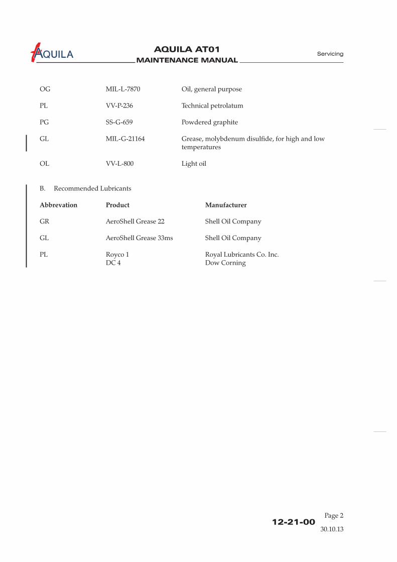
OG MIL-L-7870 Oil, general purpose
PL VV-P-236 Technical petrolatum
PG SS-G-659 Powdered graphite
GL MIL-G-21164 Grease, molybdenum disulfide, for high and lowtemperatures
OL VV-L-800 Light oil
B. Recommended Lubricants
GR AeroShell Grease 22 Shell Oil Company
GL AeroShell Grease 33ms Shell Oil Company
PL Royco 1 Royal Lubricants Co. Inc.DC 4 Dow Corning
Abbrevation Product Manufacturer
Servicing
30.10.13
Page 2

MAINTENANCE MANUAL
AQUILA AT01A
12-22-00
Page 301
LUBRICATION - SERVICING
1.
A. This section contains information on lubrication intervals for components or parts.
2.
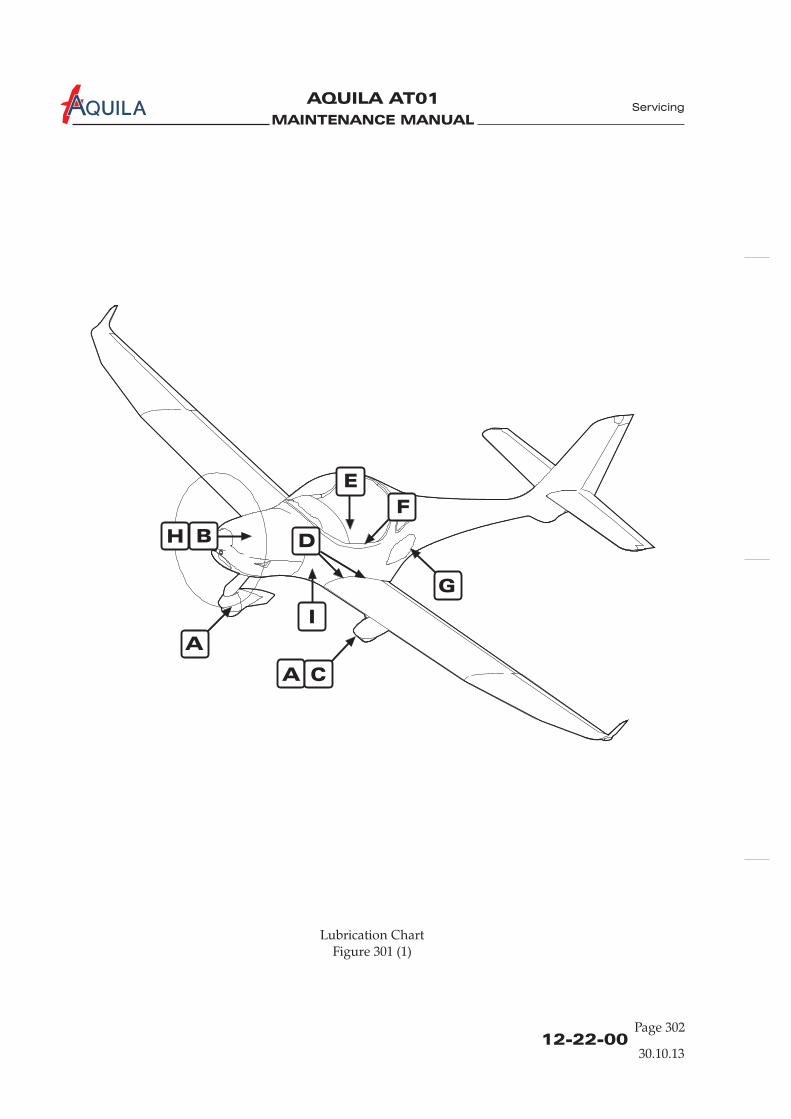
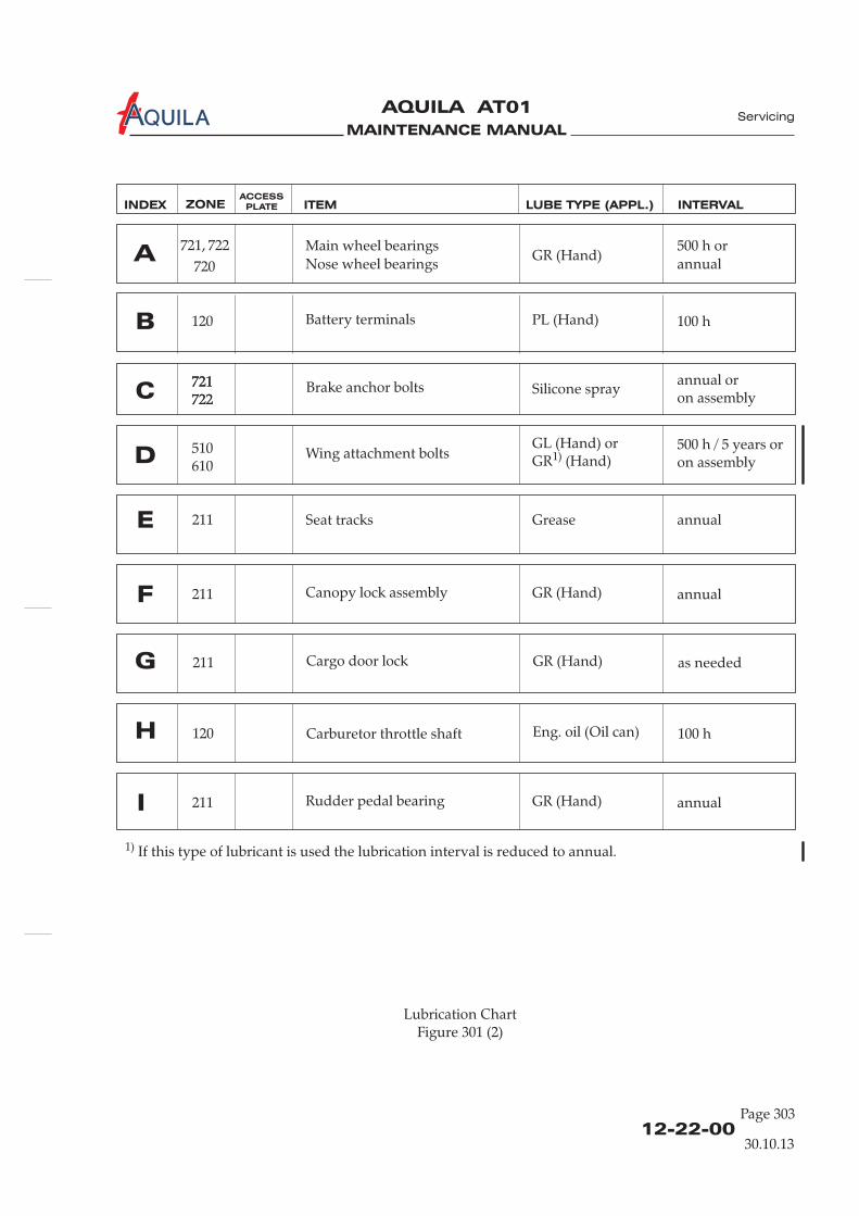
A. Figure 201 shows the location of components or parts to be regularly lubricated.The following chart contains detailed information about the lubrication interval, therecommended lubricant and the dispensing equipment.
General
Lubrication Chart
Servicing
30.10.13
MAINTENANCE MANUAL
AQUILA AT01A
Lubrication ChartFigure 301 (1)
12-22-00Page 302
Servicing
A
A
C
B
E
F
H D
G
I
30.10.13
MAINTENANCE MANUAL
AQUILA AT01A
12-22-00
Page 303
Lubrication ChartFigure 301 (2)
Servicing
Rudder pedal bearing GR (Hand) annualI 211
100 hH Carburetor throttle shaft Eng. oil (Oil can)120
as neededG Cargo door lock GR (Hand)211
Canopy lock assembly GR (Hand) annualF 211
annualE Seat tracks Grease211
500 h / 5 years oron assemblyD Wing attachment bolts
GL (Hand) orGR (Hand)1)
510610
Battery terminals PL (Hand) 100 hB 120
INDEX ZONE ITEM LUBE TYPE (APPL.) INTERVALACCESS
PLATE
30.10.13
Main wheel bearings
Nose wheel bearingsGR (Hand)
500 h or
annualA
720
722721,
Brake anchor bolts Silicone sprayannual oron assemblyC
721722721722
1) If this type of lubricant is used the lubrication interval is reduced to annual.

MAINTENANCE MANUAL
AQUILA AT01A
12-22-00Page 304
12.04.00

MAINTENANCE MANUAL
AQUILA AT01A
12-23-00
Seite 701
AIRCRAFT EXTERIOR - CLEANING AND CARE
1.
A. The good flight performance of the aircraft is achieved due to the modern construction and theuse of specific materials. For efficient laminar flow, a clean surface is very important. Therefore,one should always keep the entire aircraft clean, but especially the leading edges of the wing.
B. Information on preventive and protection such as waxing specific surfaces, is alsogiven.
2.
A. Read and adhere to all manufacturer ’s instructions, warnings and cautions on cleaning/solventcompounds used.
B. Do not use silicone-based wax to polish the aircraft exterior.C. Do not clean the aircraft at ambient temperatures close to 0°C with water.D. Cover all lubricated parts during any cleaning process.E. During the application of cleaners (e.g. cleaning the engine), the other
surfaces must be covered carefully or otherwise protected.
3.
NEVER USE GASOLINE, BENZENE, ALCOHOL, ACETONE, CARBONTETRACHLORIDE, LACQUER THINNER OR GLASS CLEANER. THESEMATERIALS WILL SOFTEN THE PLASTIC AND MAY CAUSE IT TO CRAZE.
DO NOT USE CLEANERS WITH CHEMICAL SUPPLEMENTS WHOSE EFFECT ONTHE ACRYLIC SURFACE .
A. Cleaning Canopy(1) Park the aircraft in a hangar or in the shadows, avoid places with a lot of dust caused by wind
or vehicles.(2) To prevent scratches, wash the canopy carefully with plenty of mild soap and water, using
the palm of the hand to feel and dislodge dirt and mud. A soft cloth, chamois leather orsponge should be used.
(3) Rinse thoroughly and then dry with a clean moist chamois.(4) Remove oil and grease with a cloth moistened with isopropyl alcohol.
B. Care of the Canopy(1) As a protection from mechanical and chemical actions and to cover slight cuts in the canopy,
a polish or a wax for acrylic glass can be applied in accordance with the manufacturer'sspecifications.
Clean surfaces before applying polish or wax.
General
Safety Precautions
Cleaning and Care of the Canopy
CAUTION:
CAUTION:
NOTE:
measures,
containing solvents
IS UNKNOWN
Servicing
30.10.13

MAINTENANCE MANUAL
AQUILA AT01A
12-23-00Page 702
4.
A. Procedure for cleaning the exterior surface of(1) Park the aircraft in a hangar or in the shadows, avoid places with a lot of dust caused by wind
or vehicles.(2) Close the canopy, close access / inspection doors.
KEEP WATER AWAY FROM PITOT AND STATIC PORTS AND ELECTRICAL ANDAVIONIC EQUIPMENT.
(3) Flush away loose dirt with water.
DO NOT USE HARSH ABRASIVES, ALKALINE SOAPS OR DETERGENTS.
DO NOT USE CLEANING OR POLISHING AGENTS WHICH CONTAINSILICONE.
(4) Using a soft cleaning cloth or a sponge, wash with a mild, non-alkaline soap and watersolution.
(5) Rinse thoroughly with clean water and then dry with a soft cloth or chamois.
B. Care of the Aircraft Exterior Surface(1) To protect against corrosion, mechanical and chemical actions during operation, the exterior
surfaces can be waxed with a good polish or aircraft wax in accordance with themanufacturer ’s instructions.
Clean aircraft exterior before applying polish or wax.
(2) After using cleaners containing any solvent or chemical, the relevant surfaces should alwaysbe waxed.
(3) If the aircraft is operated in a coastal or other salt-water environment, it must be washed andwaxed more frequently.
(4) A heavier wax layer on the leading edges of the wings and tail and on the cowl nose andpropeller spinner will reduce abrasion in these areas.
5.
A. Lights can be polished with a good wax and/or a liquid polishing compound. Refresh polish andhand buff once or twice a month.
B. After using a polishing compound, the lights should be waxed.
UNDER NO CIRCUMSTANCES USE ANY PETROLEUM BASED PRODUCT TOCLEAN THE LIGHTS.
Cleaning and Care of the Aircraft Exterior Surfaces
CAUTION
CAUTION:
NOTE:
Cleaning and Care of Navigation / Position / Anti-Collision Lights
CAUTION:
the aircraft
Servicing
30.10.13
MAINTENANCE MANUAL
AQUILA AT01A
12-23-00
Page 703
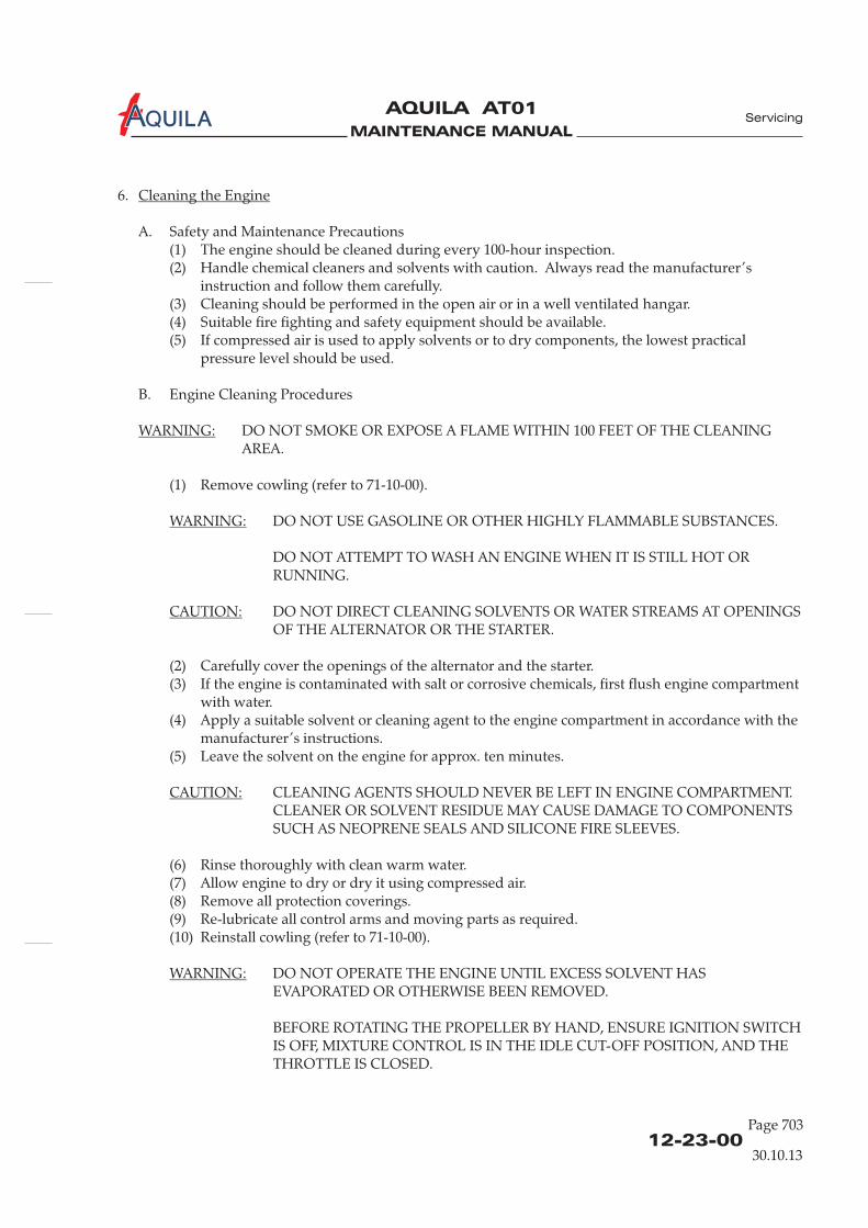
6.
A. Safety and Maintenance Precautions(1) The engine should be cleaned during every 100-hour inspection.(2) Handle chemical cleaners and solvents with caution. Always read the manufacturer ’s
instruction .(3) Cleaning should be performed in the open air or in a well ventilated hangar.(4) Suitable fire fighting and safety equipment should be available.(5) If compressed air is used to apply solvents or to dry components, the lowest practical
pressure level should be used.
B. Cleaning Procedures
DO NOT SMOKE OR EXPOSE A FLAME WITHIN 100 FEET OF THE CLEANINGAREA.
(1) Remove cowling (refer to 71-10-00).
DO NOT USE GASOLINE OR OTHER HIGHLY FLAMMABLE SUBSTANCES.
DO NOT ATTEMPT TO WASH AN ENGINE WHEN IT IS STILL HOT ORRUNNING.
DO NOT DIRECT CLEANING SOLVENTS OR WATER STREAMS AT OPENINGSOF THE ALTERNATOR OR THE STARTER.
(2) Carefully cover the openings of the alternator and the starter.(3) If the engine is contaminated with salt or corrosive chemicals, first flush engine compartment
with water.(4) Apply a suitable solvent or cleaning agent to the engine compartment in accordance with the
manufacturer ’s instructions.(5) Leave the solvent on the engine for approx. ten minutes.
CLEANING AGENTS SHOULD NEVER BE LEFT IN ENGINE COMPARTMENT.CLEANER OR SOLVENT RESIDUE MAY CAUSE DAMAGE TO COMPONENTSSUCH AS NEOPRENE SEALS AND SILICONE FIRE SLEEVES.
(6) Rinse thoroughly with clean warm water.(7) Allow engine to dry or dry it using compressed air.(8) Remove all protection .(9) Re-lubricate all control arms and moving parts as required.(10) Reinstall cowling (refer to 71-10-00).
DO NOT OPERATE THE ENGINE UNTIL EXCESS SOLVENT HASEVAPORATED OR OTHERWISE BEEN REMOVED.
BEFORE ROTATING THE PROPELLER BY HAND, ENSURE IGNITION SWITCHIS OFF, MIXTURE CONTROL IS IN THE IDLE CUT-OFF POSITION, AND THETHROTTLE IS CLOSED.
Cleaning the Engine
WARNING:
WARNING:
CAUTION:
CAUTION:
WARNING:
and follow them carefully
Engine
coverings
Servicing
30.10.13

MAINTENANCE MANUAL
AQUILA AT01A
12-23-00Page 704
CAUTION:
CAUTION:
DO NOT ROTATE THE PROPELLER CLOCKWISE.
IT IS IMPORTANT TO AVOID MOISTURE PENETRATING INTO THE WOODENCORE.
(11) Before starting the engine, rotate the propeller by hand no less than five completerevolutions.
7.
A. Clean propeller if necessary with any car wash solution or equivalent. This should be done atleast every 50 hours.Remove grease and dirt with a commercial detergent, which is suitable for polyurethane-lacquers.
Small scratches and nicks should be dealt with during routine maintenance applying a coating ofwater-resistant varnish, preferably Polyurethane.Replace damaged or missing PU strips on the propeller leading edge as soon as possible.
8.
A. The landing gear struts and wheel fairings should be washed with clear water or with a milddetergent and water.
B. After cleaning, the tires can be treated with standard tire protection.
Cleaning and Care of the Propeller
Cleaning the Landing Gear
Servicing
30.10.13
MAINTENANCE MANUAL
AQUILA AT01A
12-24-00
Page 701
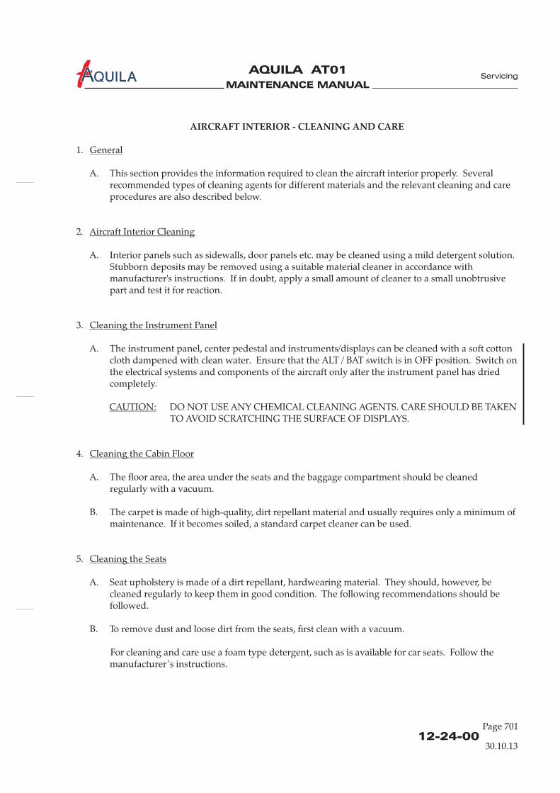
AIRCRAFT INTERIOR - CLEANING AND CARE
1.
A. This section provides the information required to clean the aircraft interior properly. Severalrecommended types of cleaning agents for different materials and the relevant cleaning and careprocedures are also described below.
2.
A. Interior panels such as sidewalls, door panels etc. may be cleaned using a mild detergent solution.Stubborn deposits may be removed using a suitable material cleaner in accordance withmanufacturer's instructions. If in doubt, apply a small amount of cleaner to a small unobtrusivepart and test it for reaction.
3.
A. The instrument panel, center pedestal and instruments/displays can be cleaned with a soft cottoncloth dampened with clean water. Ensure that the ALT / BAT switch is in OFF position. Switch onthe electrical systems and components of the aircraft only after the instrument panel has driedcompletely.
4.
A. The floor area, the area under the seats and the baggage compartment should be cleanedregularly with a vacuum.
B. The carpet is made of high-quality, dirt repellant material and usually requires only a minimum ofmaintenance. If it becomes soiled, a standard carpet cleaner can be used.
5.
A. Seat upholstery is made of a dirt repellant, hardwearing material. They should, however, becleaned regularly to keep them in good condition. The following recommendations should befollowed.
B. To remove dust and loose dirt from the seats, first clean with a vacuum.
For cleaning and care use a foam type detergent, such as is available for car seats. Follow themanufacturer ’s instructions.
General
Aircraft Interior Cleaning
Cleaning the Instrument Panel
Cleaning the Cabin Floor
Cleaning the Seats
CAUTION: DO NOT USE ANY CHEMICAL CLEANING AGENTS. CARE SHOULD BE TAKENTO AVOID SCRATCHING THE SURFACE OF DISPLAYS.
Servicing
30.10.13
MAINTENANCE MANUAL
AQUILA AT01A
12-24-00Page 702
30.10.13
Servicing
C. Blot up any liquid spilled promptly with an absorbent tissue or cloth. Press the blotting materialfirmly against the upholstery and hold for several seconds. Continue blotting until no more liquidis absorbed.
Scrape off sticky materials cautiously with a dull knife, then clean area as required.
Oil spots may be removed with household spot removers. Before using, read the instructions, testit on an obscure place on the seat and use it sparingly.

MAINTENANCE MANUAL
AQUILA AT01A
12-30-00
Page 301
UNSCHEDULED SERVICING
1.
A. This section contains those instructions necessary to carry out unscheduled servicing, for exampleremoving ice and snow from a parked aircraft.
2.
DO NOT REMOVE SNOW AND ICE FROM SURFACES USING SHARP-EDGEDINSTRUMENTS.
NEVER USE DE-ICING FLUIDS TO REMOVE SNOW OR ICE DEPOSITS FROMAIRCRAFT SURFACES.HEATED DE-ICING FLUIDS CAN DAMAGE COMPOSITE STRUCTURES DUE TOEXTREME TEMPERATURE CHANGE. SOME DE-ICING FLUIDS MAY ALSODAMAGE THE ACRYLIC GLASS OF THE CANOPY.
A. After snowfall, the snow should be removed immediately from the surface of the aircraft toprevent it from refreezing on the surface and/or in slits and gaps after it has started to thaw.
B. Procedure(1) Remove loose snow from the wing surface with a broom, working outwards from the wing
root.
The areas between wings and ailerons and stabilizers and rudders must be treatedparticularly carefully.
: DO NOT DAMAGE THE ANTENNAE.
(2) Free canopy of snow.(3) Remove snow from cowling, fuselage and empennage.
C. In the case of ice, it defrost the aircraft in a heated hangar. Allow all aircraftsurfaces to completely dry prior to flight to prevent control surfaces from freezing.
General
Removing Snow and Ice
CAUTION:
NOTE:
CAUTION
is recommended to
Servicing
30.10.13

MAINTENANCE MANUAL
AQUILA AT01A

MAINTENANCE MANUAL
AQUILA AT01A
CHAPTER 23
COMMUNICATIONS

MAINTENANCE MANUAL
AQUILA AT01A

MAINTENANCE MANUAL
AQUILA AT01A
Page 123 - TOC
Communications
30.10.13
TABLE OF CONTENTS
ChapterSection
COMMUNICATIONS - GENERAL ....................................................23-00-00 1Introduction 23-00-00 1General Description 23-00-00 1
SPEECH COMMUNICATION - DESCRIPTION .............................23-10-00 1 Garmin 430/530/650Introduction 23-10-00 1Description and Operation 23-10-00 1
SPEECH COMMUNICATION - MAINTENANCE..........................23-10-00 201General 23-10-00 201
COM Antenna Removal/Installation 23-10-00 201
SPEECH COMMUNICATION - DESCRIPTION .............................23-10-00 1 SL30/SL40Introduction 23-10-00 1Description and Operation 23-10-00 1
SPEECH COMMUNICATION - MAINTENANCE..........................23-10-00 201General 23-10-00 201NAV/COM Transceiver Removal/Installation 23-10-00 201COM Antenna Removal/Installation 23-10-00 201
AUDIO INTEGRATING - MAINTENANCE .....................................23-50-00 201 PM 501 / PM 500EXGeneral 23-50-00 201Audio Control Unit Removal/Installation 23-50-00 202
AUDIO INTEGRATING - MAINTENANCE .....................................23-50-00 201 Garmin 340/350General 23-50-00 201Audio Control Unit Removal/Installation 23-50-00 201
Title Subject Page Effectivity
SPEECH COMMUNICATION - DESCRIPTION .............................23-10-00 1 Bendix/King KX 125Introduction 23-10-00 1 Bendix/King KX 125Description and Operation 23-10-00 1 Bendix/King KX 125
SPEECH COMMUNICATION - MAINTENANCE..........................23-10-00 201 Bendix/King KX 125General 23-10-00 201 Bendix/King KX 125NAV/COM Transceiver Removal/Installation 23-10-00 201 Bendix/King KX 125COM Antenna Removal/Installation 23-10-00 201 Bendix/King KX 125Inspection/Check 23-10-00 202 Bendix/King KX 125
Garmin 430/530/650Garmin 430/530/650
Garmin 430/530/650Garmin 430/530/650
NAV/COM Transceiver Removal/Installation 23-10-00 201 Garmin 430/530/650Garmin 430/530/650
Inspection/Check 23-10-00 202 Garmin 430/530/650
GarminGarmin SL30/SL40Garmin SL30/SL40
Garmin SL30/SL40Garmin SL30/SL40Garmin SL30/SL40Garmin SL30/SL40
Inspection/Check 23-10-00 202 Garmin SL30/SL40
PM 501 / PM 500EXPM 501 / PM 500EX
Garmin 340/350Garmin 340/350

MAINTENANCE MANUAL
AQUILA AT01A

MAINTENANCE MANUAL
AQUILA AT01A
23-00-00
Communications
30.10.13
COMMUNICATIONS - GENERAL
1.
A. This chapter describes and provides maintenance instructions for components and systems usedto communicate between occupants of the aircraft and between the aircraft and other aircraft orground stations.
B. Technical publications available from the manufacturer or vendor of the various components andsystems, which are not covered in this manual, must be utilized as necessary for the maintenanceof those components and systems.
2.
A. The equipment includes a VHF COM transceiver and an intercom system.
(1) The COM is for radio communication with ground control or other aircraft.(2) Crew member headsets are connected to the COM radio and controlled by the internal or
external intercom system. It facilitates external and internal communication of the crewmembers.
14 VDC power for the transceiver is controlled by the AVIONICS switch. The radio and theintercom system are protected by the circuit breakers labeled “COM”, “NAV” and “Audio” /”Intercom”.
B. The following NAV/COM equipment and audio panel combinations may be installed:
(1)
(3)
Garmin GNS 430(W), GNS 530(W) or GTN 650 VHF communications transceiver /VOR/ILS/GS receiver / GPS receiver in combination with a Garmin GMA 340 or GMA 350audio panel.
All devices listed are mounted in the center of the instrument panel in the avionics column.
Introduction
General Description
Garmin SL40 VHF communications transceiver with an integrated intercom.(2) Bendix/King KX 125 VHF communications transceiver / VOR/ILS/GS receiver with an
integrated intercom. This NAV/COM equipment may be combined with a Bendix/KingKI 208 CDI.Garmin SL30 VHF communications transceiver / VOR/ILS/GS receiver with an integratedintercom. This NAV/COM equipment may be combined with a Garmin GI 106A CDI.
(4)
Page 1

MAINTENANCE MANUAL
AQUILA AT01A

MAINTENANCE MANUAL
AQUILA AT01A
SPEECH COMMUNICATION - DESCRIPTION
1.
A.
2.
A.
Introduction
Description and Operation
he left frontside of the KX 125 is used for controlling and displaying purposes. An active anda standby frequency can be adjusted. The left COM frequency window displays the activeCOM frequency and below the standby COM frequency. To exchange between the twofrequencies, push the frequency transfer button on the left window side. COM frequencyselection knobs are located below the COM frequency window. The larger knob adjusts thefrequency in the MHz range. The smaller knob adjusts the frequency in the KHz range, in50Khz increments. If the knob is pulled, one can also adjust the frequency in 25 kHz steps.
The VHF COM antenna is mounted to the bottom of the fuselage, behind the baggagecompartment.S/N AT01-165 and higher:The VHF COM antenna is
This section covers the portion of the system which utilizes voice communication from air-to-airor air-to-ground installations. It includes the VHF speech communications portion of theNAV/COM radio Bendix/King KX 125.The KX 125 combines a VHF communication transceiver and a VHF navigation receiver whichincludes a VOR, localizer and glideslope receiver as well as a built-in course deviation indicator.
Fig. 1 shows the KX 125 front view.
B. KX 125 VHF Speech Communication Portion – Description(1) T
(2) Up to S/N AT01-164:
laminated on the inner shell of the vertical stabilizer. The VHFNAV antenna is laminated on the inner shell of the horizontal stabilizer. Both antennascannot be removed or replaced. A second VHF COM antenna may be installed on the bottomof the fuselage when the aircraft is equipped with a second NAV/COM transceiver.
23-10-0030.10.13
EFFECTIVITY
Aircraft equipped with Bendix/King KX 125Page 1
Communications

MAINTENANCE MANUAL
AQUILA AT01A
KX 125 Front ViewFigure 1
Allen bolt hole
COMM frequency
window
NAV information
window
NAV frequency
window
COMM frequency
transfer button
standby COMM
frequency display
COMM volume /
power ON/OFF /
pull test knob
COMM frequency
selection Knobs
OBS
TX
TOFR
FLAG
PULL
25K
PULL
25K
PULL
TEST
PULL
IDENTOFF
COMM NAV
KX 125 TSO
MODE
BENDIX / KING
SBY
SBY
23-10-00Page 2
30.10.13
EFFECTIVITY
Aircraft equipped with Bendix/King KX 125
Communications

MAINTENANCE MANUAL
AQUILA AT01A Communications
SPEECH COMMUNICATION – MAINTENANCE
1.
A. The scope of maintenance is limited to the removal and installation of system components.
B. For further information, refer to Bendix/King KX 125 Maintenance Manual, P/N 5006-05335-0001,latest revision, as well as any other appropriate manufacturer publications. For overhaul andrepair, the manufacturer of the equipment has to be consulted.
2.
A. Remove NAV/COM Transceiver(1) Ensure electrical power to aircraft is OFF.(2) Insert a 3/32" hex wrench into the mounting hole (see figure 1) o
and engage hex bolt. Turn wrench counterclockwise until locking paw releases unit frommounting tray.
(3) Carefully pull out of mounting tray.
B. Install NAV/COM Transceiver(1) Ensure that all plugs at the back of the mounting tray are properly connected.(2) Carefully slide NAV/COM forward into the mounting tray.(3) Insert a 3/32" hex wrench into the mounting hole (see figure 1) o and
engage hex bolt (max. torque 1,7 Nm [15 in.lbs]). Turn wrench clockwise until locking pawsecures unit to mounting tray.
(4) Switch ON BAT and AVIONICS switches.(5) Turn NAV/COM power ON and verify LCD display illuminates.(6) Conduct a functional test of the unit.(7) Turn OFF the NAV/COM and the BAT and AVIONICS switches.
General
NAV/COM Transceiver Removal/Installation
n the face of the NAV/COM
n the face of
(only external COM antenna)
A. Remove Antenna(1) Ensure electrical power to aircraft is OFF.(2) Open baggage compartment door and remove access / inspection plate 211 KC (refer to
25-12-00).(3) Disconnect coax connector from antenna.(4) While supporting the antenna, remove 3 nuts securing antenna to fuselage.(5) Remove mounting plate.(6) Remove antenna with gasket from outside of fuselage.
Antenna Removal/Installation
NAV/COM transceiver
NAV/COM
3. COM
23-10-00
Page 201
30.10.13
EFFECTIVITY
Aircraft equipped with Bendix/King KX 125

MAINTENANCE MANUAL
AQUILA AT01A
B. Install Antenna
(1) Position antenna with gasket to fuselage.(2) Install mounting plate from inside the fuselage.(3) Secure antenna base to fuselage using screws, nuts and washers. Reinstall ground wire.(4) Check bonding of the re-installed connection. Resistance must not exceed 3 mΩ.(5) Reconnect coaxial connector and secure.(6) Install access / inspection plate 211 KC (refer to 25-12-00).
4.
A. A flight test is recommended after the KX 125 unit installation to ensure proper function. Checkthe communications transceiver for satisfactory operating range in several altitudes. Verify that theunit is communicating properly with in-panel instruments. Compare on-screen indications withthe information depicted on the CDI.
Inspection/Check
CAUTION: WIRING MUST NOT INTERFERE WITH THE OPERATION OF MOVEABLEAIRCRAFT COMPONENTS.
23-10-00Page 202
EFFECTIVITY
Aircraft equipped with Bendix/King KX 125
30.10.13
Communications

MAINTENANCE MANUAL
AQUILA AT01A
23-10-0030.10.13
EFFECTIVITY
SPEECH COMMUNICATION – DESCRIPTION
1.
A. This section covers the portion of the system which utilizes voice communication from air-to-airor air-to-ground installations. It includes the VHF speech communications portion of theNAV/COM radio Garmin GNS 430(W), GNS 530(W) or GTN 650.The GNS 430(W) / GNS 530(W) / GTN 650 is a combination of a VHF communications transceiverand a navigation management system which includes a GPS sensor and VOR, localizer andglideslope receivers.For information on the navigation management system of these systems, refer to 34-00-00 and theapplicable user manuals.
B. For a complete description of the GNS 430(W) / GNS 530(W) / GTN 650, refer to theGarmin GNS 430 Pilot's Guide and Reference, P/N 190-00140-00, latest revision, the
Garmin GTN 650 Pilot's Guide and Reference, P/N 190-01004-00, latest revision.
2.
A. Fig. 1 shows the GNS 430 / GTN 650 front view.
B. GNS 430(W) / GNS 530(W) / GTN 650 VHF Speech Communication Portion - Description(1) The speech communications portion consists of a digitally tuned integrated VHF
communications (COM) transceiver. The transceiver receives all narrow- and wide-bandVHF communications transmissions within a frequency range of 118.000 MHz to 136.975MHz in 25.0 kHz steps (760 channels) or for use in Europe in 8.33 kHz steps (2280 channels).
(2) Up to S/N AT01-164:The VHF COM antenna is mounted to the bottom of the fuselage, behind the baggagecompartment.S/N AT01-165 and higher:
A second VHF COM antenna may be installed on the bottomof the fuselage when the aircraft is equipped with a second NAV/COM transceiver.
Introduction
Description and Operation
Garmin GNS 430W Pilot's Guide and Reference, P/N 190-00356-00, latest revision, theGarmin GNS 530 Pilot's Guide and Reference, P/N 190-00181-00, latest revision, theGarmin GNS 530W Pilot's Guide and Reference, P/N 190-00357-00, latest revision, or to the
laminated on the inner shell of the vertical stabilizer. The VHFNAV antenna is laminated on the inner shell of the horizontal stabilizer. Both antennascannot be removed or replaced.
The VHF COM antenna is
Aircraft equipped with GarminGNS 430(W) / GNS 530(W) / GTN 650
Page 1
Communications
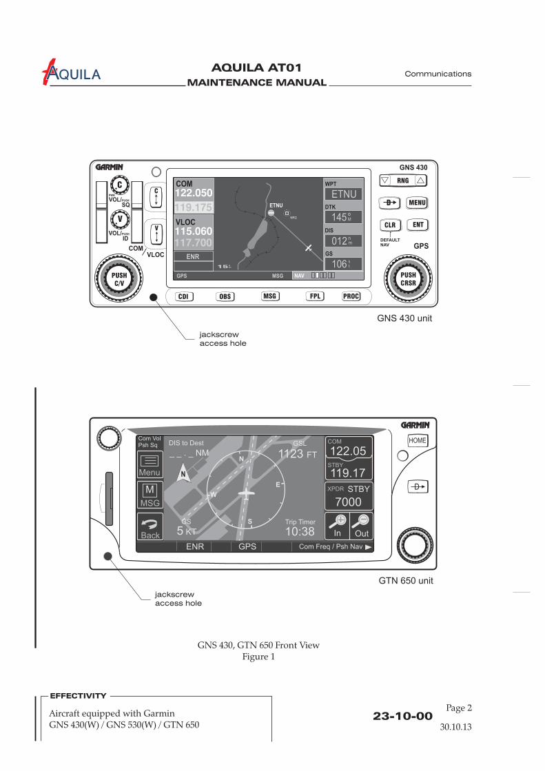
MAINTENANCE MANUAL
AQUILA AT01A
23-10-00Page 2
30.10.13
GNS 430, GTN 650 Front ViewFigure 1
EFFECTIVITY
Aircraft equipped with GarminGNS 430(W) / GNS 530(W) / GTN 650
jackscrew
access hole
jackscrew
access hole
Communications
WPT
DTK
DIS
GS
GNS 430 unit
GTN 650 unit
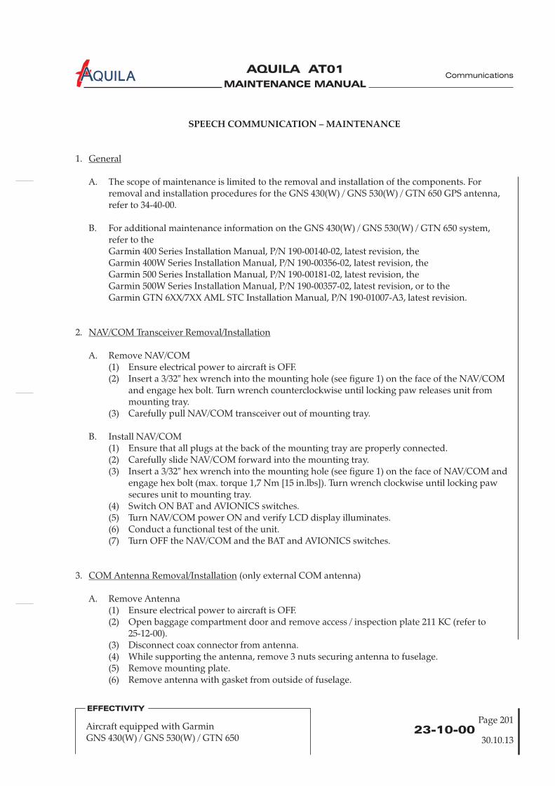
MAINTENANCE MANUAL
AQUILA AT01A
23-10-00
Page 201
30.10.13
EFFECTIVITY
Aircraft equipped with GarminGNS 430(W) / GNS 530(W) / GTN 650
SPEECH COMMUNICATION – MAINTENANCE
1.
A. The scope of maintenance is limited to the removal and installation of the components. Forremoval and installation procedures for the GNS 430(W) / GNS 530(W) / GTN 650 GPS antenna,refer to 34-40-00.
B. For additionalefer to the
Garmin GTN 6XX/7XX AML STC Installation Manual, P/N 190-01007-A3, latest revision.
General
maintenance information on the GNS 430(W) / GNS 530(W) / GTN 650 system,rGarmin 400 Series Installation Manual, P/N 190-00140-02, latest revision, theGarmin 400W Series Installation Manual, P/N 190-00356-02, latest revision, theGarmin 500 Series Installation Manual, P/N 190-00181-02, latest revision, theGarmin 500W Series Installation Manual, P/N 190-00357-02, latest revision, or to the
(only external COM antenna)
A. Remove Antenna(1) Ensure electrical power to aircraft is OFF.(2) Open baggage compartment door and remove access / inspection plate 211 KC (refer to
25-12-00).(3) Disconnect coax connector from antenna.(4) While supporting the antenna, remove 3 nuts securing antenna to fuselage.(5) Remove mounting plate.(6) Remove antenna with gasket from outside of fuselage.
Antenna Removal/Installation
2.
A. Remove NAV/COM(1) Ensure electrical power to aircraft is OFF.(2) Insert a 3/32" hex wrench into the mounting hole (see figure 1) on the face of the NAV/COM
and engage hex bolt. Turn wrench counterclockwise until locking paw releases unit frommounting tray.
(3) Carefully pull NAV/COM out of mounting tray.
B. Install NAV/COM(1) Ensure that all plugs at the back of the mounting tray are properly connected.(2) Carefully slide NAV/COM forward into the mounting tray.(3) Insert a 3/32" hex wrench into the mounting hole (see figure 1) on the face of NAV/COM and
engage hex bolt (max. torque 1,7 Nm [15 in.lbs]). Turn wrench clockwise until locking pawsecures unit to mounting tray.
(4) Switch ON BAT and AVIONICS switches.(5) Turn NAV/COM power ON and verify LCD display illuminates.(6) Conduct a functional test of the unit.(7) Turn OFF the NAV/COM and the BAT and AVIONICS switches.
3.
NAV/COM Transceiver Removal/Installation
COM
transceiver
Communications

MAINTENANCE MANUAL
AQUILA AT01A Communications
23-10-00Page 202
30.10.13
Aircraft equipped with GarminGNS 430(W) / GNS 530(W) / GTN 650
EFFECTIVITY
B. Install Antenna
(1) Position antenna with gasket to fuselage.(2) Install mounting plate from inside the fuselage.(3) Secure antenna base to fuselage using screws, nuts and washers. Reinstall ground wire.(4) Check bonding of the re-installed connection. Resistance must not exceed 3 m .(5) Reconnect coaxial connector and secure.(6) Install access / inspection plate 211 KC (refer to 25-12-00).
4.
A. A flight test is recommended after the GNS 430(W) / GNS 530(W) / GTN 650 unit installation toensure proper function. Check the communications transceiver for satisfactory operating range inseveral altitudes. Verify that the unit is communicating properly with in-panel instruments.Compare on-screen indications with the information depicted on the CDI.
Ω
Inspection/Check
CAUTION: WIRING MUST NOT INTERFERE WITH THE OPERATION OF MOVEABLEAIRCRAFT COMPONENTS.

MAINTENANCE MANUAL
AQUILA AT01A
SPEECH COMMUNICATION - DESCRIPTION
1.
A. This section covers the portion of the system which utilizes voice communication from air-to-airor air-to-ground installations. It includes the VHF speech communications portion of theNAV/COM radio Garmin SL30 or SL40.The SL30 combines a VHF communication transceiver and a VHF navigation receiver whichincludes a VOR, localizer and glideslope receiver as well as a built-in course deviation indicator.For information on the navigation portion of the SL30, refer to the SL30 NAV/COM Pilot's Guide,
, latest revision.The SL40 is a derivative of the SL30 having only its communication functions. The SL30 and SL40contain an independent, voice-activated intercom unit with a separate power supply.
B. For a complete description of the SL30 / SL40, refer to the Garmin SL30 Pilot's Guide,P/N 560-0403-01 or to the SL40 Pilot’s Guide, P/N 560-0954-02, latest revision.
2.
A. Fig. 1 shows the SL30 / SL40 front view.
B. SL30 VHF Speech Communication Portion / SL40 – Description(1) The knob on the left side of the SL30 / SL40 controls power on/off, volume and squelch test.
To turn the power on, the knob must be rotated clockwise past the detent. Once thetransceiver is turned on, clockwise rotation of the knob increases the speaker and headphonevolume level, counter-clockwise rotation reduces the volume level. Frequency tuning isaccomplished by rotating the large (for MHz settings) and small (for kHz settings) knobs toselect the desired standby frequency. The active frequency is displayed on the left side of thedisplay, the standby frequency is indicated on the right side adjacent to the active frequency.To switch between the frequencies, the frequency flip/flop button must be pressed. Aphotocell located on the upper left side of the display automatically adjusts the brightness ofthe display to the ambient light conditions.
(2) Up to S/N AT01-164:
Introduction
Description and Operation
P/N 560-0403-01
laminated on the inner shell of the vertical stabilizer. The VHFNAV antenna is laminated on the inner shell of the horizontal stabilizer. Both antennascannot be removed or replaced. A second VHF COM antenna may be installed on the bottomof the fuselage when the aircraft is equipped with a second NAV/COM transceiver.
The VHF COM antenna is mounted to the bottom of the fuselage, behind the baggagecompartment.S/N AT01-165 and higher:The VHF COM antenna is
23-10-0030.10.13
EFFECTIVITY
Aircraft equipped with Garmin SL30 / SL40
Communications
Page 1

MAINTENANCE MANUAL
AQUILA AT01A
23-10-00Page 2
30.10.13
EFFECTIVITY
Aircraft equipped with Garmin SL30 / SL40
Communications
Garmin SL30 / SL40, Front ViewFigure 1
TX
118.00 s136.00 135 oT
SL30
PULL SQUELCH
VOL
OFF
COM NAV SYS OBS T/F ID SEL ENT
frequencyflip/flop
NAVradio
ident
photocell
activefrequency
to/fromindication
GraphicCDIBearing
transmitannunciator
functionannunciators
power /volume /squelch
COMradio
to/from
OBSselect
enter small innerknob
large outerknob
systemsettings
select
mode select
standbyfrequency
standbysymbol
TX
119.80 s121.50SL40
PULL SQUELCH
VOL
OFF
EC MON RCL MEM
frequencyflip/flop
frequencymonitor
photocell
activefrequency
standbyfrequency
standbysymbol
transmitannunciator
power /volume /squelch
emergencychannel
storememory
small innerknob
large outerknob
recallmemory
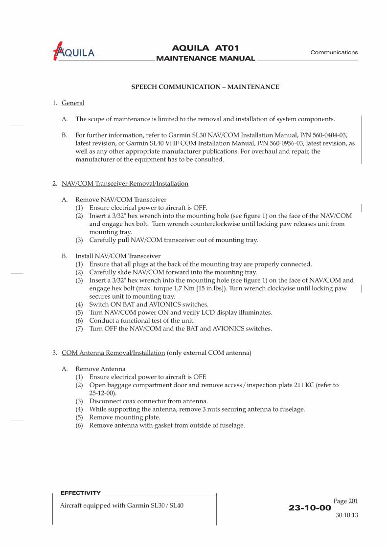
MAINTENANCE MANUAL
AQUILA AT01A
SPEECH COMMUNICATION – MAINTENANCE
1.
A. The scope of maintenance is limited to the removal and installation of system components.
B. For further information, refer to Garmin SL30 NAV/COM Installation Manual, P/N 560-0404-03,latest revision, or Garmin SL40 VHF COM Installation Manual, P/N 560-0956-03, latest revision, aswell as any other appropriate manufacturer publications. For overhaul and repair, themanufacturer of the equipment has to be consulted.
2.
A. Remove NAV/COM Transceiver(1) Ensure electrical power to aircraft is OFF.(2) Insert a 3/32" hex wrench into the mounting hole (see figure 1) o
and engage hex bolt. Turn wrench counterclockwise until locking paw releases unit frommounting tray.
(3) Carefully pull out of mounting tray.
B. Install NAV/COM Transceiver(1) Ensure that all plugs at the back of the mounting tray are properly connected.(2) Carefully slide NAV/COM forward into the mounting tray.(3) Insert a 3/32" hex wrench into the mounting hole (see figure 1) o and
engage hex bolt (max. torque 1,7 Nm [15 in.lbs]). Turn wrench clockwise until locking pawsecures unit to mounting tray.
(4) Switch ON BAT and AVIONICS switches.(5) Turn NAV/COM power ON and verify LCD display illuminates.(6) Conduct a functional test of the unit.(7) Turn OFF the NAV/COM and the BAT and AVIONICS switches.
General
NAV/COM Transceiver Removal/Installation
n the face of the NAV/COM
n the face of NAV/COM
(only external COM antenna)
A. Remove Antenna(1) Ensure electrical power to aircraft is OFF.(2) Open baggage compartment door and remove access / inspection plate 211 KC (refer to
25-12-00).(3) Disconnect coax connector from antenna.(4) While supporting the antenna, remove 3 nuts securing antenna to fuselage.(5) Remove mounting plate.(6) Remove antenna with gasket from outside of fuselage.
Antenna Removal/Installation
NAV/COM transceiver
3. COM
23-10-00
Page 201
30.10.13
EFFECTIVITY
Aircraft equipped with Garmin SL30 / SL40
Communications
MAINTENANCE MANUAL
AQUILA AT01A
B. Install Antenna
(1) Position antenna with gasket to fuselage.(2) Install mounting plate from inside the fuselage.(3) Secure antenna base to fuselage using screws, nuts and washers. Reinstall ground wire.(4) Check bonding of the re-installed connection. Resistance must not exceed 3 mΩ.(5) Reconnect coaxial connector and secure.(6) Install access / inspection plate 211 KC (refer to 25-12-00).
4.
A. A flight test is recommended after the SL30 / SL40 unit installation to ensure proper function.Check the communications transceiver for satisfactory operating range in several altitudes. Verifythat the unit is communicating properly with in-panel instruments. Compare on-screenindications with the information depicted on the CDI (SL30 only).
Inspection/Check
CAUTION: WIRING MUST NOT INTERFERE WITH THE OPERATION OF MOVEABLEAIRCRAFT COMPONENTS.
23-10-00Page 202
EFFECTIVITY
Aircraft equipped with Garmin SL30 / SL40
Communications
30.10.13

MAINTENANCE MANUAL
AQUILA AT01A
Intercom Control PanelFigure 201
POWER
ISO
ALL
Pilot
Volume Squelch SquelchVolume
Co-Pilotpower LED
volume
squelch
mode switch
only left / both
23-50-00
Page 201
Communications
AUDIO INTEGRATING - MAINTENANCE
1.
A. This section covers that portion of the system which controls the output of the communicationand navigation receivers to crew member headphones and speakers, and the output of the crewmember microphones to the communication transmitters.
B. The intercom system consists primarily of the PM 501 / PM 500EX audio control unit, located onthe instrument panel, the pilot and co-pilot audio jacks mounted on the middle console near theseat backs and the push-to-talk (PTT) switches located on the control sticks.
C. The intercom system enables the use of headsets on both seats:(1) The communication between crew members;(2) Separate adjustment of sound volume at each headset;(3) Separate regulation of the responding level of the microphones;(4) The connection of the left or both crew members for audible monitoring of air-ground
communication.
General
30.10.13
EFFECTIVITY
Aircraft equipped with PS EngineeringPM 501 / PM 500EX

MAINTENANCE MANUAL
AQUILA AT01A
23-50-00Page 202
Communications
2.
A. Remove Audio Control Unit(1) Ensure electrical power to aircraft is OFF.(2) Disconnect the plug at the back of the audio control unit.(3) Remove control knob caps o .(4) Loosen and remove nuts attaching audio control unit on the left side to mounting bracket.(5) Holding the audio control unit, remove two screws on front panel fixing the control unit to
instrument panel.(6) Remove audio control unit.
B. Install Audio Control Unit(1) Install audio control unit to the instrument panel and secure using two screws.(2) Secure audio control unit on the left-hand side to the mounting bracket using two nuts.
During installation make sure that the position of control knob caps is conform tothe position of the control knob axles.
(3) Install the control knob caps o .(4) Reconnect the plug connector and secure as required at the back of the audio control unit.(5) Conduct a functional test of the unit.
Audio Control Unit Removal/Installation
NOTE:
n the front panel of the audio control unit
n the face of the audio control unit
30.10.13
EFFECTIVITY
Aircraft equipped with PS EngineeringPM 501 / PM 500EX
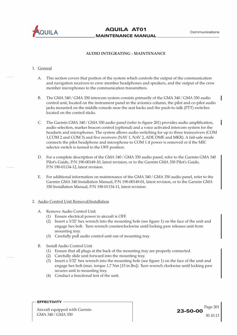
MAINTENANCE MANUAL
AQUILA AT01A
AUDIO INTEGRATING - MAINTENANCE
1.
A. This section covers that portion of the system which controls the output of the communicationand navigation receivers to crew member headphones and speakers, and the output of the crewmember microphones to the communication transmitters.
B. The GMA 340 / GMA 350 intercom system consists primarily of the GMA 340 / GMA 350 audiocontrol unit, located on the instrument panel in the avionics column, the pilot and co-pilot audiojacks mounted on the middle console near the seat backs and the push-to-talk (PTT) switcheslocated on the control sticks.
The Garmin GMA 340 / GMA 350 audio panel (refer to figure 201) provides audio amplification,audio selection, marker beacon control (optional) and a voice activated intercom system for theheadsets and microphones. The system allows audio switching for up to three transceivers (COM1,COM 2 and COM 3) and five receivers (NAV 1, NAV 2, ADF, DME and MKR). A fail-safe modeconnects the pilot headphone and microphone to COM 1 if power is removed or if the MICselector switch is turned to the OFF position.
D. For a complete description of the GMA 340 / GMA 350 audio panel, refer to the Garmin GMA 340to the Garmin GMA 350 Pilot's Guide,
P/N 190-01134-12, latest revision.
E. F efer to theGarmin GMA 340 Installation Manual, P/N 190-00149-01, latest revision, or to the
.
2.
A. Remove Audio Control Unit(1) Ensure electrical power to aircraft is OFF.(2)
B. Install Audio Control Unit(1)
(4) Conduct a functional test of the unit.
General
Audio Control Unit Removal/Installation
C.
Pilot's Guide, P/N 190-00149-10, latest revision, or
or additional information on maintenance of the GMA 340 / GMA 350 audio panel, rGarmin GMA
350 Installation Manual, P/N 190-01134-11, latest revision
Insert a 3/32" hex wrench into the mounting hole (see figure 1) on the face of the unit andengage hex bolt. Turn wrench counterclockwise until locking paw releases unit frommounting tray.
(3) Carefully pull audio control unit out of mounting tray.
Ensure that all plugs at the back of the mounting tray are properly connected.(2) Carefully slide unit forward into the mounting tray.(3) Insert a 3/32" hex wrench into the mounting hole (see figure 1) on the face of the unit and
engage hex bolt (max. torque 1,7 Nm [15 in.lbs]). Turn wrench clockwise until locking pawsecures unit to mounting tray.
23-50-00
Page 201
EFFECTIVITY
Aircraft equipped with GarminGMA 340 / GMA 350
Communications
30.10.13

MAINTENANCE MANUAL
AQUILA AT01A
COM1
MIC
COM1
SENS
TEST
COM2
MIC
COM2 NAV1 DME
COM3
MIC
COM
1/2
COM3 NAV2 ADF
SPKR PILOT
PA CREW
CABIN AUDIO ICS ISOLATION
MKRMUTEA O M
HI
LO
PILOT COPILOT
SQ
OFF/
VOL
SQ
VOL
PULLPASS
VOL
MKR/BCN COM NAV
ICS
jackscrew
access hole
GMA 340 / GMA 350 Audio Panel, Front ViewFigure 201
23-50-00Page 202
EFFECTIVITY
Aircraft equipped with GarminGMA 340 / GMA 350
Communications
30.10.13
jackscrew
access hole

MAINTENANCE MANUAL
AQUILA AT01A
CHAPTER 24
ELECTRICAL POWER

MAINTENANCE MANUAL
AQUILA AT01A

MAINTENANCE MANUAL
AQUILA AT01A
Page 124 - TOC
Electrical Power
TABLE OF CONTENTS
ChapterSection
ELECTRICAL POWER - GENERAL...............................................................24-00-00 1Introduction 24-00-00 1General Description 24-00-00 1
ELECTRICAL POWER - TROUBLESHOOTING.........................................24-00-00 101Troubleshooting 24-00-00 101
ALTERNATOR SYSTEM - DESCRIPTION....................................................24-20-00 1Introduction 24-20-00 1Description and Operation 24-20-00 1
ALTERNATOR SYSTEM - MAINTENANCE ................................................24-20-00 201General 24-20-00 201External Alternator Removal/Installation 24-20-00 201
BATTERY SYSTEM - DESCRIPTION ............................................................24-30-00 1Introduction 24-30-00 1Description and Operation 24-30-00 1
BATTERY SYSTEM - MAINTENANCE..........................................................24-30-00 201General 24-30-00 201Battery Removal/Installation 24-30-00 201
EXTERNAL POWER - MAINTENANCE.......................................................24-40-00 201 Ext. powerGeneral 24-40-00 201 Ext. powerExternal Power Receptacle Removal/Installation 24-40-00 201 Ext. powerExternal Power Relay Removal/Installation 24-40-00 201 Ext. powerAdjustment/Test 24-40-00 203 Ext. powerInspection/Check 24-40-00 203 Ext. power
ELECTRICAL LOAD DISTRIBUTION - DESCRIPTION............................24-60-00 1Introduction 24-60-00 1Description and Operation 24-60-00 1
CIRCUIT BREAKER - MAINTENANCE........................................................24-61-00 201General 24-61-00 201Circuit Breaker Removal/Installation 24-61-00 201
Title Subject Page Effectivity
External Alternator Drive Belt Removal/Installation 24-20-00 201Rectifier-Regulator Unit Removal/Installation 24-20-00 203 Night-VFR
Battery Relay Removal/Installation 24-30-00 201
30.10.13
MAINTENANCE MANUAL
AQUILA AT01A
ELECTRICAL SYSTEM WIRING - MAINTENANCE..................................24-97-00 201General 24-97-00 201Splicing 24-97-00 201Wire Replacement 24-97-00 201
TABLE OF CONTENTS (Cont.)
ChapterSection
Title Subject Page Effectivity
24 - TOCPage 2
30.10.13
Electrical Power
MAINTENANCE MANUAL
AQUILA AT01A
24-00-00
Electrical Power
ELECTRICAL POWER - GENERAL
1.
A. This chapter describes the units and components, which generate, control and supply AC and DCelectrical power for other systems.
2.
A. The aircraft is equipped with a 12V DC electrical system. It is powered by a belt driven 600Walternator and a 12V battery which is installed on the front-right side of the firewall.All essential electrical accessories in the system are protected by circuit breakers. These are to befound on the right side of the instrument panel.Electrical power distribution to the various accessories is characterized through functionality andsafety. It is accomplished by two main bus bars - the aircraft bus bar and the avionics bus bar.
If the aircraft is equipped for Night-VFR, the internal alternator integrated in the ROTAX engine isactivated in order to provide a second independent power source.To supply DC to the aircraft electrical system this permanent magnet generator is used incombination with a ROTAX specified rectifier-regulator, which is installed at the front-left side ofthe firewall.
As an option, the aircraft may be equipped with an external power receptacle mounted on theright side of fuselage just forward of the firewall. The receptacle permits the use of an externalpower source for cold weather starting and maintenance procedures requiring reliable power foran extended period.
Introduction
General Description
30.10.13
Page 1

MAINTENANCE MANUAL
AQUILA AT01A

MAINTENANCE MANUAL
AQUILA AT01A
ELECTRICAL POWER - TROUBLESHOOTING
TROUBLE POSSIBLE CAUSE REMEDY
1.
A. If a power problem or a complete blackout occurs, first check all connections to the componentsand the circuit breakers.
B. Troubleshooting Chart:
No alternator ALT 1 switch OFF Turn switch ON.output, voltmeter Defective alternator Replace alternator.indicates 12 V, Circuit breaker activated Troubleshoot circuit and reset circuitammeter indicates (open) breaker.discharge
Battery will not Battery is discharged Step 1:supply power or Place BAT switch and LDG LIGHTis incapable of switch in ON Position. Measure batterycranking engine. voltage. A normally charged battery
will indicate 12,5 volts or more. If .voltage is low, proceed to step 2.If voltage is normal proceed to step 3.
Defective battery Step 2:Charge battery approx. 30 minutes.If the battery tester indicates a goodbattery, the cause was a dischargedbattery. If the tester indicates a defectivebattery, replace the battery.
Defective wiring or electrical Step 3:connection between battery With switch BAT in ON position,terminal and battery relay. measure voltage between battery terminal
and battery relay.Correct value would be 0 V.If voltage reads 0 V, proceed to step 4.If a voltage reading is obtained, checkwiring between battery terminal andbattery relay.
Defective battery relay. Step 4:With switch BAT in ON position,measure voltage between relay terminals.Correct value would be 0 V.If voltage reads 0 V, proceed to step 5.
Troubleshooting
24-00-00
Page 101
Electrical Power
30.10.13

MAINTENANCE MANUAL
AQUILA AT01A
If a voltage reading is obtained, replacebattery relay.
Defective wiring or electrical Step 5:connection between battery With switch BAT in ON position,relay and starter relay. measure voltage between starter side relay
terminal, and starter relay.
If a voltage reading is obtained, checkwiring between starter side relay terminaland starter relay
Correct value would be 0 V.
24-00-00Page 102
Electrical Power
30.10.13

MAINTENANCE MANUAL
AQUILA AT01A
24-20-00
ALTERNATOR SYSTEM - DESCRIPTION
1.
A. The alternator system supplies the electrical equipment with electrical power when the engine isrunning and is the main current source in the power supply design.
B. The alternator system consists of the following components:
- external alternator- alternator circuit breakers- alternator warning light(s)- alternator
2.
A. The external alternator (ALT 1) is installed in the forward left side of the engine, to the left of thegearbox. It is belt-driven and incorporates an internal voltage regulator.
The alternator circuit breaker is installed in the circuit breaker panel on the far right side of theinstrument panel and it protects the system from overloading. The red ALT 1 warning light islocated in the row of annunciator lights on the instrument panel and indicates undervoltage.
Introduction
Description and Operation
switch- internal alternator (only Night-VFR equipped aircraft)- rectifier-regulator unit (only Night-VFR equipped aircraft)
The external alternator issupplied with an excitation voltage by the battery when the ALT1/BAT switch is turned ON. Whenthe engine is running, the alternator generates a three-phase current that is rectified and regulatedby the internal voltage regulator. The voltage regulator supplies a 14 V DC voltage to the aircraftbus when engine speed is at or above 800 rpm. The maximum current load is approx. 45 A.
B. Aircraft equipped for Night-VFR additionally use the internal alternator (ALT 2) integrated in theROTAX engine as a second independent power source. This permanent magnet alternator (250W)does not need any external voltage supply for excitation. To supply DC to the aircraft electricalsystem it is used in combination with a ROTAX specified rectifier-regulator unit, which is installedon the front-left side of the firewall. The red ALT 2 warning light is located in the row ofannunciator lights on the instrument panel. It is controlled by the rectifier-regulator unit andindicates undervoltage.
C. An ammeter monitors power supply. The voltmeter is connected with the aircraft bus bar. Theammeter measures the charge or discharge current to/from the battery. Both instruments arefound on the right side of the instrument panel in the instrument cluster.
D. The alternator warning lights and ammeter discharge indication may illuminate during low rpmwith an electrical load on the system, for example during low rpm taxi. The lights will extinguishat higher rpm.
E. Refer to the ROTAX Installation Manual (P/N 898643) for more information on the external andinternal alternators and the rectifier-regulator unit.
Electrical Power
30.10.13
Page 1

MAINTENANCE MANUAL
AQUILA AT01A
24-20-00Page 2
Electrical Power
ROTAX Internal Alternator System (Schematic, Night-VFR equipped aircraft only)Figure 2
External Alternator System (Schematic)Figure 1
external alternator
warning light
“ALT 1”
ALT 1
BAT
to a
ircra
ft b
us s
yste
m
circuit breaker
“ALT 1 Excitation”
circuit breaker
“Warning Lights”
circuit breaker
“ALT 1”
fire
wa
ll
30.10.13
warning light
“ALT 2”
to a
ircra
ft b
us s
yste
m
circuit breaker
“Warning Lights”
circuit breaker
“ALT 2”
ROTAX
internal alternator
rectifier-
regulator
unit

MAINTENANCE MANUAL
AQUILA AT01A
24-20-00
Page 201
ALTERNATOR SYSTEM - MAINTENANCE
1.
A. Maintenance is limited to the (external) alternator, drive belt andrectifier-regulator unit (only Night-VFR equipped aircraft). Refer to the appropriate ROTAXpublications for maintenance procedures on the internal alternator.
2.
A. Remove External Alternator(1) Ensure electrical power to aircraft and ignition switch is OFF. Remove key.(2) Remove cowling (refer to 71-10-00).(3) Disconnect battery (refer to 24-30-00).(4) Disconnect electrical cables (include ground cable) from alternator.(5) Cut safety wire and loosen adjusting bolt and alternator mounting bolts.(6) Slip drive belt off alternator pulley.(7) Remove mounting bolts securing alternator to engine. Remove alternator from engine.
B. Install External Alternator(1) Position alternator into mounting bracket.(2) Install shim and mounting bolt as shown in figure 201. Do not tighten yet.(3) Loosely secure lower alternator mounting boss to adjustment cam using washers and bolt
(refer to figure 201).(4) Place drive belt on alternator pulley. Verify pulleys are aligned.
IF A NEW DRIVE BELT IS INSTALLED: THE ENGINE BELT TENSION SHOULDBE RECHECKED WITHIN THE FIRST 15 TO 20 HOURS OF OPERATION.
(5) Apply a torque wrench to the alternator pulley nut and adjust belt tension so the belt slips at:(a) 10 - 12 Nm (88 - 106 in.lbs) of torque with a used belt;(b) 15 - 18 Nm (133 - 159 in.lbs) of torque with a new belt
(6) Tighten adjusting bolt. Torque to 22 Nm (195 in.lbs).(7) Tighten alternator mounting bolts.
(a) Torque M10 bolt (upper alternator mounting bracket) to 40 Nm (355 in.lbs).(b) Torque M8 bolt to 22 Nm (195 in.lbs).
(8) Safety wire all bolts.(9) Reconnect electrical cables including the ground cable.(10) Reconnect battery (refer to 24-30-00).(11) Install cowling (refer to 71-10-00).
3.
A. Remove Alternator Drive Belt(1) Ensure electrical power to aircraft and ignition switch is OFF. Remove key.(2) Remove engine cowling (refer to 71-10-00).(3) Disconnect battery (refer to 24-30-00).
General
External Alternator Removal/Installation
CAUTION:
External Alternator Drive Belt Removal/Installation
removal and installation of the
Electrical Power
30.10.13

MAINTENANCE MANUAL
AQUILA AT01A
24-20-00Page 202
Electrical Power
External Alternator InstallationFigure 201
30.10.13
A
ADetail-
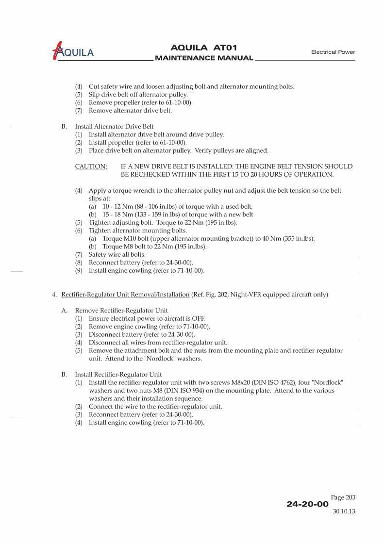
MAINTENANCE MANUAL
AQUILA AT01A
(4) Cut safety wire and loosen adjusting bolt and alternator mounting bolts.(5) Slip drive belt off alternator pulley.(6) Remove propeller (refer to 61-10-00).(7) Remove alternator drive belt.
B. Install Alternator Drive Belt(1) Install alternator drive belt around drive pulley.(2) Install propeller (refer to 61-10-00).(3) Place drive belt on alternator pulley. Verify pulleys are aligned.
IF A NEW DRIVE BELT IS INSTALLED: THE ENGINE BELT TENSION SHOULDBE RECHECKED WITHIN THE FIRST 15 TO 20 HOURS OF OPERATION.
(4) Apply a torque wrench to the alternator pulley nut and adjust the belt tension so the beltslips at:(a) 10 - 12 Nm (88 - 106 in.lbs) of torque with a used belt;(b) 15 - 18 Nm (133 - 159 in.lbs) of torque with a new belt
(5) Tighten adjusting bolt. Torque to 22 Nm (195 in.lbs).(6) Tighten alternator mounting bolts.
(a) Torque M10 bolt (upper alternator mounting bracket) to 40 Nm (355 in.lbs).(b) Torque M8 bolt to 22 Nm (195 in.lbs).
(7) Safety wire all bolts.(8) Reconnect battery (refer to 24-30-00).(9) Install engine cowling (refer to 71-10-00).
CAUTION:
4. (Ref. Fig. 202, Night-VFR equipped aircraft only)
A. Remove Rectifier-Regulator Unit(1) Ensure electrical power to aircraft is OFF.(2) Remove engine cowling (refer to 71-10-00).(3) Disconnect battery (refer to 24-30-00).(4) Disconnect all wires from rectifier-regulator unit.(5) Remove the attachment bolt and the nuts from the mounting plate and rectifier-regulator
unit. Attend to the ''Nordlock'' washers.
B. Install Rectifier-Regulator Unit(1) Install the rectifier-regulator unit with two screws M8x20 (DIN ISO 4762), four ''Nordlock''
washers and two nuts M8 (DIN ISO 934) on the mounting plate. Attend to the variouswashers and their installation sequence.
(2) Connect the wire to the rectifier-regulator unit.(3) Reconnect battery (refer to 24-30-00).(4) Install engine cowling (refer to 71-10-00).
Rectifier-Regulator Unit Removal/Installation
24-20-00
Page 203
Electrical Power
30.10.13
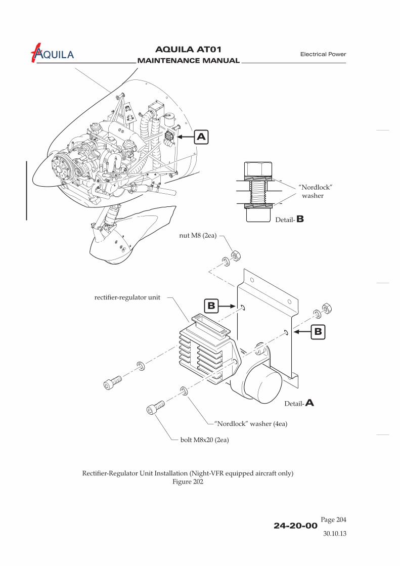
MAINTENANCE MANUAL
AQUILA AT01A
24-20-00Page 204
Electrical Power
Rectifier-Regulator Unit Installation (Figure 202
Night-VFR equipped aircraft only)
rectifier-regulator unit
“Nordlock” washer (4ea)
bolt M8x20 (2ea)
nut M8 (2ea)
30.10.13
ADetail-
A
“Nordlock”washer
BDetail-
B
B
MAINTENANCE MANUAL
AQUILA AT01A
24-30-00
BATTERY SYSTEM - DESCRIPTION
1.
A. The battery system supplies power to the electrical equipment if the alternator fails. It representsthe auxiliary power source in supply design.
B. The battery system consists of the following components:
- battery- battery relay- BAT switch- voltmeter- ammeter
2.
A. The aircraft has a 12-volt, 19-ampere hour, lead-acid battery, which is installed in a battery tray onthe front-right side of the firewall. It is accessible by removing the upper engine cowling. Thebattery box is vented. The vent line discharges out of the bottom of the engine cowling,preventing the build up of dangerous or explosive gases in the engine compartment. The batteryrelay is fixed above the battery at the engine mount.
B. To connect the battery to the aircraft bus the switch, located on the lower left instrumentpanel, must be in the ON position, thus connecting one battery relay terminal to aircraft ground.The other relay terminal is permanently supplied with a positive voltage by the battery. In thisway the aircraft bus bar is supplied with current via the battery relay.The voltmeter is connected with the aircraft bus bar. The ammeter measures the charge ordischarge current to/from the battery via a shunt. Both instruments are located on the rightinstrument panel in the instrument cluster.
Introduction
Description and Operation
BAT
Electrical Power
30.10.13
Page 1

MAINTENANCE MANUAL
AQUILA AT01A
Battery System (Schematic)Figure 1
battery-
relay
to aircraft
bus bar
to clock,
ELT
battery
ALT 1
BAT
ammeter
AMPS- +
DC VOLTS
circuit breaker
“Battery”
firewall
BATTERY SYSTEM (SCHEMATIC)
24-30-00
Electrical Power
30.10.13
Page 2
voltmeter
MAINTENANCE MANUAL
AQUILA AT01A
24-30-00
Page 201
BATTERY SYSTEM - MAINTENANCE
1.
A. Maintenance is limited to the removal and installation of the battery and the battery relay.For information on the regular servicing required, refer to 12-17-00.
2.
A. Remove Battery(1) Ensure BAT switch is in OFF position.(2) Remove upper engine cowling (refer to 71-10-00).(3) Remove battery hold down strap.(4) Disconnect battery cables.(5) Remove battery from mounting tray.
B. Install Battery(1) Place battery into mounting tray and secure with battery hold down strap.(2) Reconnect battery vent line.(3) Reconnect battery cables.(4) Install engine cowling (refer to 71-10-00).
General
Battery Removal/Installation
CAUTION:
NOTE:
Battery Relay Removal/Installation
CAUTION:
ALWAYS DISCONNECT THE BATTERY BEFORE DOING ANY MAINTENANCE ONTHE ELECTRICAL SYSTEM. DISCONNECT THE NEGATIVE LEAD FIRST. RECONNECTTHE NEGATIVE LEAD LAST. SECURE THE BATTERY LEADS FROM ACCIDENTALCONNECTION DURING MAINTENANCE WORKS.
It is recommended to remove the battery from the aircraft before doing any maintenanceon the electrical system to avoid the risk of accidental connection.
3. (Ref. Fig. 201)
A. Remove Battery Relay(1) Ensure electrical power to aircraft is OFF.(2) Remove engine cowling (refer to 71-10-00).(3) Disconnect battery (refer to 24-30-00).(4) Identify and disconnect wires at battery relay.(5) Remove nuts, washers and bolts securing relay to engine mount and remove relay.
B. Install Battery Relay(1) Position and secure battery relay to engine mount using bolts, washers and nuts.(2) Identify and reconnect wires to relay.
DO NOT REMOVE INNER NUT WHEN ASSEMBLING. USE WRENCH TOHOLD INNER NUT IN PLACE WHEN APPLYING OUTER NUT.
Electrical Power
30.10.13

MAINTENANCE MANUAL
AQUILA AT01A
24-30-0030.10.13
Page 202
Electrical Power
(3) Reconnect battery (refer to 24-30-00).(4) Install engine cowling (refer to 71-10-00).
A
ADetail-
batteryrelay
1,4-2 Nm
5-6 Nm
12-18 in.lbs
44-55 in.lbs
Battery Relay InstallationFigure 201

MAINTENANCE MANUAL
AQUILA AT01A
24-40-00
Page 201
Electrical Power
EXTERNAL POWER - MAINTENANCE
1.
A. This section covers that portion of the system which connects external electrical power to theaircraft's electrical systems. It includes items such as external power receptacle and relays.
B. As an option the aircraft may be equipped with an external power receptacle mounted on theright side of the engine mount, just below the battery. The standard, oval shaped, 3-pin receptacleis accessible through an hinged access plate in the right side of the engine cowling. Furthermore,the system includes an external power relay attached to the engine mount and a relay behind theinstrument panel. For wiring refer to 91-00-00.When a 12 V DC power supply is connected to the external power receptacle the shorter, thirdconnector engages the external power relay, which connects the external power to the aircraftmain bus. Simultaneously, the battery switch will be disconnected from the ground terminal bythe second relay behind the instrument panel. This prevents an energizing of the battery relaywhile an external power supply is being used.The signal power to the external power relay contains an isolation diode to prevent reversepolarity.
C. Maintenance is limited to the removal and installation of components.
2. (Ref. Fig. 201)
A. Remove External Power Receptacle(1) Ensure electrical power to aircraft is OFF.
(3) Disconnect battery (refer to 24-30-00).(4) Identify and disconnect all wires at EPU receptacle.(5) Remove nuts, washers and bolts securing receptacle to engine mount and remove receptacle.
B. Install External Power Receptacle(1) Position and secure EPU receptacle to engine mount using bolts, washers and nuts.(2) Identify and reconnect wires to EPU receptacle.(3) Reconnect battery (refer to 24-30-00).(4) Install engine cowling (refer to 71-10-00).(5) Perform an external power system functional check (refer to “Adjustment/Test” below).
3.
A. Remove External Power Relay(1) Ensure electrical power to aircraft is OFF.(2) Remove engine cowling (refer to 71-10-00).(3) Disconnect battery (refer to 24-30-00).(4) Identify and disconnect wires at external power relay.(5) Remove nuts, washers and bolts securing relay to engine mount and remove relay.
General
External Power Receptacle Removal/Installation
External Power Relay Removal/Installation
(2) Remove engine cowling (refer to 71-10-00).
(Ref. Fig. 201)
30.10.13Aircraft equipped with an external power receptacle
EFFECTIVITY

MAINTENANCE MANUAL
AQUILA AT01A
24-40-00Page 202
Electrical Power
External Power Receptacle InstallationFigure 201
Aircraft equipped with an external power receptacle
EFFECTIVITY
A
ADetail-
ground
power
Signal
4 Pl.
30.10.13
B
BDetail-
externalpowerrelay
8212A04N
8212B04
8212A20
1,4-2 Nm
5-6 Nm
12-18 in.lbs
44-55 in.lbs

MAINTENANCE MANUAL
AQUILA AT01A
B. Install External Power Relay(1) Position and secure external power relay to engine mount using bolts, washers and nuts.(2) Identify and reconnect wires to external power relay.
(3) Reconnect battery (refer to 24-30-00).(4) Install engine cowling (refer to 71-10-00).(5) Perform an external power system functional check (refer to “Adjustment/Test below).
4.
A. External Power System Functional Check(1) Connect an 14 V DC external power supply to aircraft.(2) Place the BAT switch to the ON position.(3) Verify the voltmeter shows 14 V.(4) Disconnect external power supply from aircraft.(5) The voltmeter must show 12 V.(6) Place the BAT switch in OFF position.
5.
A. External Power System Inspection/Check(1) Check latching mechanism and hinge of the external power access plate for integrity and
condition.(2) Remove engine cowling (refer to 71-10-00).(3) Remove glare shield (refer to 31-10-00).(4) Check external power receptacle for security.(5) Check system relays for condition and security.(6) Inspect electrical cables of the system for proper routing, chafing, broken or loose terminals,
general condition, and sharp bends in wiring.(7) Verify the external power placard is firmly in place and legible.(8) Install glare shield (refer to 31-10-00).(9) Install engine cowling (refer to 71-10-00).
CAUTION: DO NOT REMOVE INNER NUT WHEN ASSEMBLING. USE WRENCH TOHOLD INNER NUT IN PLACE WHEN APPLYING OUTER NUT.
Adjustment/Test
Inspection/Check
24-40-00
Page 203
Electrical Power
Aircraft equipped with an external power receptacle
EFFECTIVITY
30.10.13

MAINTENANCE MANUAL
AQUILA AT01A

MAINTENANCE MANUAL
AQUILA AT01A
24-60-00
ELECTRICAL LOAD DISTRIBUTION - DESCRIPTION
1.
A. Distribution of electrical power supplied by the external and optional the internal alternator andthe battery is accomplished by bus bars. The bus architecture allows power to be routed to theessential circuitry if any one of the main power sources fails.All essential electrical accessories in the system are protected by push pull type circuit breakerswhich can be reset in flight. The circuit breaker panel is on the far right of the instrument paneland each circuit breaker is labeled. All circuit breakers have their rated values identified on thetop of the shaft.
B. For power routing throughout the aircraft, refer to wiring diagrams shown in 91-00-00.
2.
A. The electrical system has two main bus bars: the aircraft bus bar and the avionics bus bar. Allsystems are connected to the aircraft bus bar. Theavionics bus bar supplies the avionics equipment with power.
B. The external alternator output and the battery are connected with the aircraft bus via 50A circuitbreakers. Optional the internal alternator is connected with the aircraft bus via a rectifier-regulatorunit and a 25A circuit breaker. The circuit breakers are located on the right side of the instrumentpanel in the circuit breaker panel.The current is distributed from the aircraft bus bar via circuit breakers to the electrical circuits ofseveral systems and components and via the switch to the avionics bus bar. Fromthere, it is further distributed to the several components of the avionics equipment via circuitbreakers. The AVIONICS switch allows avionics equipment to be removed separately from theresidual electrical system.
Introduction
Description and Operation
which are essential for aircraft operation
AVIONICS
Electrical Power
30.10.13
Page 1

MAINTENANCE MANUAL
AQUILA AT01A

MAINTENANCE MANUAL
AQUILA AT01A
CIRCUIT BREAKER - MAINTENANCE
1.
A. The circuit breaker panel is equipped with circuit breakers of the push to reset type.One terminal of each switch/breaker is directly connected to the appropriate bus bar, the other iswired to the component/system it protects.
2.
A. Remove Circuit Breaker(1) Ensure electrical power to aircraft is OFF.(2) Disconnect battery (refer to 24-30-00).(3) Remove glare shield (refer to 31-10-00).(4) Disconnect wire and bus from selected circuit breaker.(5) Remove retaining ring and washer from circuit breaker on the front of the instrument panel.(6) Remove circuit breaker.
It may be necessary to loosen more than one circuit breaker to remove the selectedcircuit breaker.
B. Install Circuit Breaker(1) Place circuit breaker into position on the instrument panel and secure.(2) Identify and connect wire and bus to the selected circuit breaker.(3) Reinstall glare shield (refer to 31-10-00).(4) Reconnect battery (refer to 24-30-00).
General
Circuit Breaker Removal/Installation
NOTE:
" "
24-61-00
Page 201
Electrical Power
30.10.13

MAINTENANCE MANUAL
AQUILA AT01A
MAINTENANCE MANUAL
AQUILA AT01A
ELECTRICAL SYSTEM WIRING - MAINTENANCE
1.
A. Repairs of the electrical system wiring are limited to the replacement and splicing of electricalwires. In general all repairs have to be carried out by certified repair stations or properly certifiedand trained persons.
B. Carry out a complete functional check of the concerned equipment after every repair.
C. Refer to 91-00-00 for wiring diagrams.
A. Splicing is permitted on wiring as long as it does not affect the reliability and theelectromechanical characteristics of the wiring. Splicing of power wires, coaxial cables, shieldedwires or wire sizes above AWG 18 is not permitted. There should not be more than one splice inany one wire segment between any two connectors or other disconnect points.
3 “Splicing splicing procedures andequipment
General
2.
3.
A. If wires are replaced, they have to be replaced by identical ones (same MIL specification andAWG). New wires have to be routed, fixed and protected in the same manner as the old wires.
Splicing
Wire Replacement
Refer toAC 43.13-1B, chapter 11, section 1 ” for further information on
.
24-97-00
Page 201
30.10.13
Electrical Power

MAINTENANCE MANUAL
AQUILA AT01A
MAINTENANCE MANUAL
AQUILA AT01A
CHAPTER 25
EQUIPMENT / FURNISHINGS

MAINTENANCE MANUAL
AQUILA AT01A

MAINTENANCE MANUAL
AQUILA AT01A
Page 125 - TOC
Equipment / Furnishings
TABLE OF CONTENTS
ChapterSection
EQUIPMENT / FURNISHINGS - GENERAL................................................25-00-00 1Introduction 25-00-00 1General Description 25-00-00 1
SEATS - MAINTENANCE ................................................................................25-10-00 201General 25-10-00 201Seat Removal/Installation 25-10-00 201Gas Spring Strut Assembly Removal/Installation 25-10-00 203
RESTRAINT SYSTEM - MAINTENANCE.....................................................25-11-00 201General 25-11-00 201Restraint System Removal/Installation 25-11-00 201
CABIN INTERIOR - MAINTENANCE ..........................................................25-12-00 201General 25-12-00 201Panels, Coverings and Carpets Removal/Installation 25-12-00 202
CARGO TIE-DOWNS - MAINTENANCE.....................................................25-50-00 201General 25-50-00 201
EMERGENCY EQUIPMENT - DESCRIPTION............................................25-60-00 1Introduction 25-60-00 1Description and Operation 25-60-00 1
EMERGENCY LOCATER TRANSMITTER - MAINTENANCE.................25-62-00 201General 25-62-00 201ELT Removal/Installation 25-62-00 201ELT Antenna Removal/Installation 25-62-00 201Battery Replacement 25-62-00 202Adjustment/Test 25-62-00 202Inspection/Check 25-62-00 203
FIRE EXTINGUISHER - MAINTENANCE....................................................25-66-00 201 Air TotalGeneral 25-66-00 201Description and Operation 25-66-00 201Maintenance Instructions 25-66-00 201
Title Subject Page Effectivity
Air TotalAir TotalAir Total
Fire Extinguisher Removal/Installation 25-66-00 201 Air Total
FIRE EXTINGUISHER - MAINTENANCE....................................................25-66-00 201 H3RGeneral 25-66-00 201 H3RDescription and Operation 25-66-00 201 H3RMaintenance Instructions 25-66-00 201 H3RFire Extinguisher Removal/Installation 25-66-00 202 H3R
30.10.13

MAINTENANCE MANUAL
AQUILA AT01A
Page 0225 - TOC
15.09.09
Equipment / Furnishings
MAINTENANCE MANUAL
AQUILA AT01A
25-00-00
EQUIPMENT / FURNISHINGS - GENERAL
1.
A. This chapter describes removable items of equipment and interior furnishings contained in thecabin and baggage compartment.
2.
A. The seats can be adjusted back and forward. The restraint system of each seat is attached to thefuselage structure. It consists of shoulder harness with an inertia-reel retractor and lap belts whichallow for complete freedom of movement of the upper torso area. In the event of a suddendeceleration, the reels lock to provide positive restraint for the user.
B. The cabin interior is easy to care for and designed for functionally. Thefor maintenance purposes.
C. The baggage compartment is directly behind the seats. It can be loaded through the baggagecompartment door on the left side of fuselage.
D. An emergency locator transmitter (ELT) is installed. The transmitter unit is fitted to the baggagecompartment floor immediately behind the right seat back.
Introduction
General Description
panels and coverings canbe removed
Equipment / Furnishings
30.10.13
Page 1

MAINTENANCE MANUAL
AQUILA AT01A
MAINTENANCE MANUAL
AQUILA AT01A
25-10-00
Page 201
Equipment / Furnishings
SEATS - MAINTENANCE
1.
A. The seats are made from fiber composite materials and equipped with integrated safety head restsand removable, hard-wearing seat cushions.An infinitely adjustable seat meets the requirements of a wide range of pilots. The seat track isangled upward for forward travel so that shorter people will be positioned slightly higher as theyadjust the seat forward. A lockable oil/gas spring strut holds the seat in the desired position.To position the seat, push the seat position control knob located below the seat frame on the right,slide the seat into position, and then release the knob.
2.
A. Remove Seat(1) Remove seat cushion.(2) Remove control knob at the remote control of the gas spring locking valve and then the
retaining nut which secures the remote control to attachment bracket.(3) Disconnect gas spring strut from seat by removing bolt at strut end.(4) Remove bolts securing seat to seat rails and remove seat.
B. Install Seat(1) Position seat and secure to seat rails with bolts.(2) Slide remote control of gas spring locking valve into hole of attachment bracket.(3) Connect gas spring strut to seat using bolt, washer and self locking nut.(4) Secure remote control to attachment bracket with retaining nut and install control knob.(5) Install seat cushion.
3.
A. Remove Seat Rails(1) Remove seat (refer to “Seat Removal” above).(2) Remove screws securing seat rails to fuselage structure and remove seat rails.
B. Install Seat Rails(1) Position seat rails and secure to fuselage structure with screws.(2) Install seat (refer to “Seat Installation” above).
General
Seat Removal/Installation
Seat Rails Removal/Installation
30.10.13

MAINTENANCE MANUAL
AQUILA AT01A
25-10-00Page 202
Seat InstallationFigure 201
Equipment / Furnishings
30.10.13
ADetail-
A

MAINTENANCE MANUAL
AQUILA AT01A
25-10-00
Page 203
Equipment / Furnishings
4.
A. Remove Gas Spring Strut Assembly(1) Remove seat cushion.(2)
(3) Disconnect gas spring strut from seat by removing bolt at strut end.(4) Disconnect gas spring strut from fuselage structure by removing bolt at strut base and
remove gas spring strut assembly.
B. Install Gas Spring Strut Assembly(1) Slide remote control of gas spring locking valve into hole of attachment bracket.(2) Reconnect gas spring strut to seat using bolt, washer and self locking nut.(3) Connect gas spring strut to fuselage structure using bolt, washer and self locking nut.(4) Secure remote control to attachment bracket with retaining nut and install control knob.(5) Install seat cushion.
Gas Spring Strut Assembly Removal/Installation
Remove control knob at the remote control of the gas spring locking valve and then theretaining nut which secures the remote control to attachment bracket.
30.10.13

MAINTENANCE MANUAL
AQUILA AT01A

MAINTENANCE MANUAL
AQUILA AT01A
RESTRAINT SYSTEM - MAINTENANCE
1.
A. The seats are equipped with automatic, four point seat belts/shoulder harness assemblies. Afasten the seat belts/shoulder harness. The design incorporates an
inertia reel system for the shoulder portion. The shoulder harnesses are attached to the baggagecompartment bulkhead, and allow complete freedom of movement of the upper torso. In theevent of a sudden deceleration, the reels lock automatically to protect the occupants.The seat belts are attached to fittings on the landing gear bulkhead.
B. Maintenance is limited to the removal and installation of restraint systems.
2.
A. Remove Restraint System(1) Open baggage compartment bulkhead access panel.(2) Remove baggage compartment floor board.(3) Remove bolts securing inertia reel to baggage compartment bulkhead and remove shoulder
harness from aircraft.(4) Remove bolts securing seat belts to fuselage structure and remove seat belts.
B. Install Restraint System(1) Install inertia reel in baggage compartment bulkhead using hex bolts, washers and self-
locking nuts. Route shoulder belts through belt guide in the seat back.(2) Attach seat belts to fuselage structure using hex bolts, spacers, washers and self- locking nuts.(3) Install all items removed for access.
General
Restraint System Removal/Installation
central rotary buckle is used to
25-11-00
Page 201
Equipment / Furnishings
30.10.13

MAINTENANCE MANUAL
AQUILA AT01A
MAINTENANCE MANUAL
AQUILA AT01A
CABIN INTERIOR - MAINTENANCE
1.
A. The panels, coverings and carpets can be removed for maintenance purposes.
B. For cabin interior cleaning and care refer to chapter 12, section "Cabin interior - Cleaning andCare".
2.
A. Panels are typically attached to the aircraft fuselage structure .
B. Seat cushions and carpets are fixed with hook-and-loop fasteners.
C. See figure 201 for an exploded view of the cabin interior.
General
Panels, Coverings and Carpets Removal and Installation
with small screws
25-12-00
Page 201
30.10.13
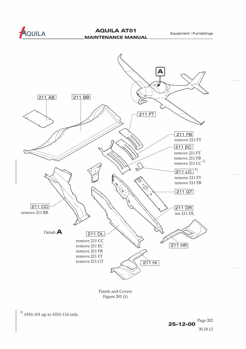
MAINTENANCE MANUAL
AQUILA AT01A
25-12-00Page 202
Equipment / Furnishings
Panels and CoversFigure 201 (1)
30.10.13
211 DL
remove 211 BB
remove 211 CCremove 211 ECremove 211 FBremove 211 FTremove 211 GT
remove 211 FT
remove 211 FTremove 211 FBremove 211 LC
1)
remove 211 FTremove 211 FB
see 211 DL
211 AB 211 BB
211 FT
211 FB
211 EC
211 LC1)
211 GT
211 DR211 CC
211 Hl
211 HR
A
ADetail-
1)AT01-101 up to AT01-114 only.

MAINTENANCE MANUAL
AQUILA AT01A
25-12-00
Page 203
Equipment / Furnishings
remove 211 ILremove 211 IR
211 IC211 IR
211 IL
211 JB
211 KC
B
BDetail-
Panels and CoversFigure 201 (2)
30.10.13

MAINTENANCE MANUAL
AQUILA AT01A Equipment / Furnishings

MAINTENANCE MANUAL
AQUILA AT01A
CARGO TIE-DOWNS - MAINTENANCE
1.
A. Eight cargo tie-down rings are provided to secure baggage. Baggage nets may be used to holdbaggage in position during flight.The cargo tie-down rings are secured directly to the floorboard by nutplates or they secure thefloorboard to the supports.
General
25-50-00
Page 201
Equipment / Furnishings
30.10.13

MAINTENANCE MANUAL
AQUILA AT01A

MAINTENANCE MANUAL
AQUILA AT01A
EMERGENCY EQUIPMENT - DESCRIPTION
1.
A. This section describes those items of equipment carried for use in emergencies and includes theemergency locator transmitter (ELT) and a fire extinguisher.
B. As standard the aircraft is equipped with a Kannad 406 AF Compact ELT. Due to the multiplicityof equipment coming onto the market a different ELT may be installed. Refer to the manualsprovided by the equipment manufacturer for further information.
2. (Ref. Fig. 1)
A. The ELT is designed to transmit on the frequencies 121,5 MHz (some ELT's additionally 243 MHz)and 406 MHz. The basic emergency frequency 121,5 MHz is mainly used for homing in the finalstages of the rescue operations. The 406 MHz frequency is used by the COSPAS-SARSAT satellitesfor precise pinpointing and identification of the aircraft in distress.The ELT can be activated either automatically when a crash occurs or manually by means of acontrol switch on the front panel. The incorporated g-switch activates the unit if it detects adeceleration along the longitudinal axis.Once activated, the transmitter operates continuously on 121,5 (and 243 MHz).Simultaneously, during the first 24 hours of operation, a 112 bit digital message (identification onlyin the short message configuration) is transmitted on 406 MHz every 50 seconds.
B. The ELT is installed on the baggage compartment floor immediately behind the right seat back.The ELT antenna is located on top of fuselage behind the cabin. The ELT remote control panel /indicator (RCPI) is mounted on the instrument panel, right side.For in-flight use, both the front panel of the ELT and the RCPI are easily accessible from the pilot’snormal seated position. If it is equipped with a portable antenna the unit can be removed fromthe aircraft and used as a personal locating device when it is necessary to leave the aircraft after anaccident.The ELT front panel includes a 3-position ARM/OFF/ON switch.With the control switch in ARM position the ELT is in stand-by mode for automatic activation, thenormal operation mode. Selecting the ON position starts the transmission on 121,5 / 243 MHzimmediately after the self-test, the 406 MHZ transmission starts after 50 seconds.
Introduction
Description and Operation
MHZ
Equipment / Furnishings
25-60-0030.10.13
Page 1

MAINTENANCE MANUAL
AQUILA AT01A
ELT Main Components (Kannad 406 AF Compact)Figure 1
Page 2
Equipment / Furnishings
25-60-00
A
ADetail-
BDetail-
CDetail-
DDetail-
D
C
B
ELT remote controlpanel / indicator
(RCPI)
ELT antenna
BNC connector
red LED
main switch
Velcro strap
mounting bracket
RC connector
30.10.13

MAINTENANCE MANUAL
AQUILA AT01A
EMERGENCY LOCATER TRANSMITTER - MAINTENANCE
1.
A. This section covers removal and installation procedures of ELT components as well necessaryperiodic maintenance.
B. Consider all publications / requirements of the appropriate national authority regarding ELToperation and maintenance.
C. Refer to the publications provided by the ELT manufacturer for complete information oninstallation, programming, operation and maintenance of the ELT.
2.
A. Remove ELT(1) Open the baggage compartment door.(2) Turn the main transmitter control switch on the ELT to the OFF position.(3) Disconnect antenna cable from front panel off the ELT.(4) Unstrap transmitter unit and remove from aircraft.
B. Install ELT
THE ELT MUST BE MOUNTED WITH THE ARROW (PRINTED ON THEBATTERY CASE AND LABELED “FLIGHT DIRECTION”) POINTING IN THEDIRECTION OF FLIGHT.
(1) Install transmitter on to mounting tray with arrow on battery case pointing in direction offlight and secure with strap.
(2) Connect antenna cable to front of ELT.(3) Perform a functional test (refer to “Adjustment/Test” below).
3.
A. Remove ELT Antenna(1) Open baggage compartment door and remove access / inspection plate 211 KC (refer to
25-12-00).(2) Disconnect antenna cable from antenna base.(3) Supporting the antenna, remove nuts and washers securing ELT antenna to fuselage, remove
ground wire.(4) Remove mounting plate.(5) Remove antenna with gasket from topside of fuselage.
General
ELT Removal/Installation
WARNING:
ELT Antenna Removal/Installation
Page 201
Equipment / Furnishings
25-62-0030.10.13
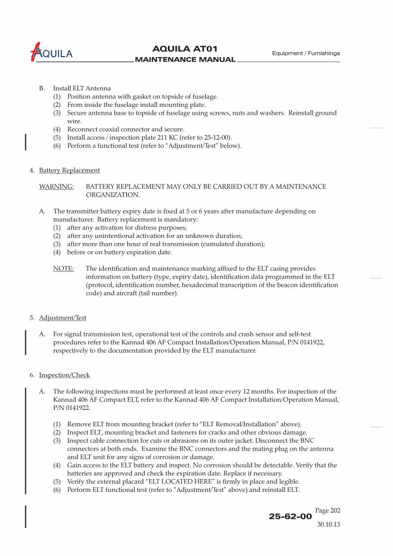
MAINTENANCE MANUAL
AQUILA AT01A
B. Install ELT Antenna(1) Position antenna with gasket on topside of fuselage.(2) From inside the fuselage install mounting plate.(3) Secure antenna base to topside of fuselage using screws, nuts and washers. Reinstall ground
wire.(4) Reconnect coaxial connector and secure.(5) Install access / inspection plate 211 KC (refer to 25-12-00).(6) Perform a functional test (refer to “Adjustment/Test” below).
4.
BATTERY REPLACEMENT MAY ONLY BE CARRIED OUT BY A MAINTENANCEORGANIZATION.
A. The transmitter battery expiry date is fixed at 5 or 6 years after manufacture. Battery replacement is mandatory:
(1) after any activation for distress purposes;(2) after any unintentional activation for an unknown duration;(3) after more than one hour of real transmission (cumulated duration);(4) before or on battery expiration date.
The identification and maintenance marking affixed to the ELT casing providesinformation on battery (type, expiry date), identification data programmed in the ELT(protocol, identification number, hexadecimal transcription of the beacon identificationcode) and aircraft (tail number).
5.
Battery Replacement
WARNING:
NOTE:
Adjustment/Test
depending onmanufacturer
A. For signal transmission test, operational test of the controls and crash sensor and self-testprocedures refer to the Kannad 406 AF Compact Installation/Operation Manual, P/N 0141922,respectively to the documentation provided by the ELT manufacturer.
6.
A. The following inspections must be performed at least once every 12 months. For inspection of theKannad 406 AF Compact ELT, refer to the Kannad 406 AF Compact Installation/Operation Manual,P/N 0141922.
(1) Remove ELT from mounting bracket (refer to “ELT Removal/Installation” above).(2) Inspect ELT, mounting bracket and fasteners for cracks and other obvious damage.(3) Inspect cable connection for cuts or abrasions on its outer jacket. Disconnect the BNC
connectors at both ends. Examine the BNC connectors and the mating plug on the antennaand ELT unit for any signs of corrosion or damage.
(4) Gain access to the ELT battery and inspect. No corrosion should be detectable. Verify that thebatteries are approved and check the expiration date. Replace if necessary.
(5) Verify the external placard “ELT LOCATED HERE” is firmly in place and legible.(6) Perform ELT functional test (refer to “Adjustment/Test” above) and reinstall ELT.
Inspection/Check
Page 202
Equipment / Furnishings
25-62-00
30.10.13
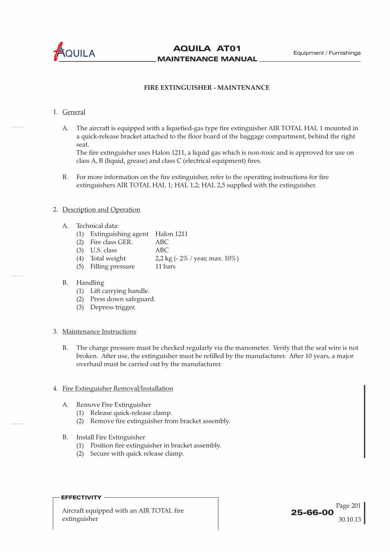
MAINTENANCE MANUAL
AQUILA AT01A
25-66-00
Page 201
Equipment / Furnishings
FIRE EXTINGUISHER - MAINTENANCE
1.
A. The aircraft is equipped with a liquefied-gas type fire extinguisher AIR TOTAL HAL 1 mounted ina quick-release bracket attached to the floor board of the baggage compartment, behind the rightseat.The fire extinguisher uses Halon 1211, a liquid gas which is non-toxic and is approved for use onclass A, B (liquid, grease) and class C (electrical equipment) fires.
B. For more information on the fire extinguisher, refer to the operating instructions for fireextinguishers AIR TOTAL HAL 1; HAL 1,2; HAL 2,5 supplied with the extinguisher.
2.
A. Technical data:(1) Extinguishing agent Halon 1211(2) Fire class GER. ABC(3) U.S. class ABC(4) Total weight 2,2 kg (- 2% / year, max. 10%)(5) Filling pressure 11 bars
B. Handling(1) Lift carrying handle.(2) Press down safeguard.(3) Depress trigger.
3.
B. The charge pressure must be checked regularly via the manometer. Verify that the seal wire is notbroken. After use, the extinguisher must be refilled by the manufacturer. After 10 years, a majoroverhaul must be carried out by the manufacturer.
General
Description and Operation
Maintenance Instructions
4.
A. Remove Fire Extinguisher(1) Release quick-release clamp.(2) Remove fire extinguisher from bracket assembly.
B. Install Fire Extinguisher(1) Position fire extinguisher in bracket assembly.(2) Secure with quick release clamp.
Fire Extinguisher Removal/Installation
Aircraft equipped with an AIR TOTAL fireextinguisher
EFFECTIVITY
30.10.13

MAINTENANCE MANUAL
AQUILA AT01A
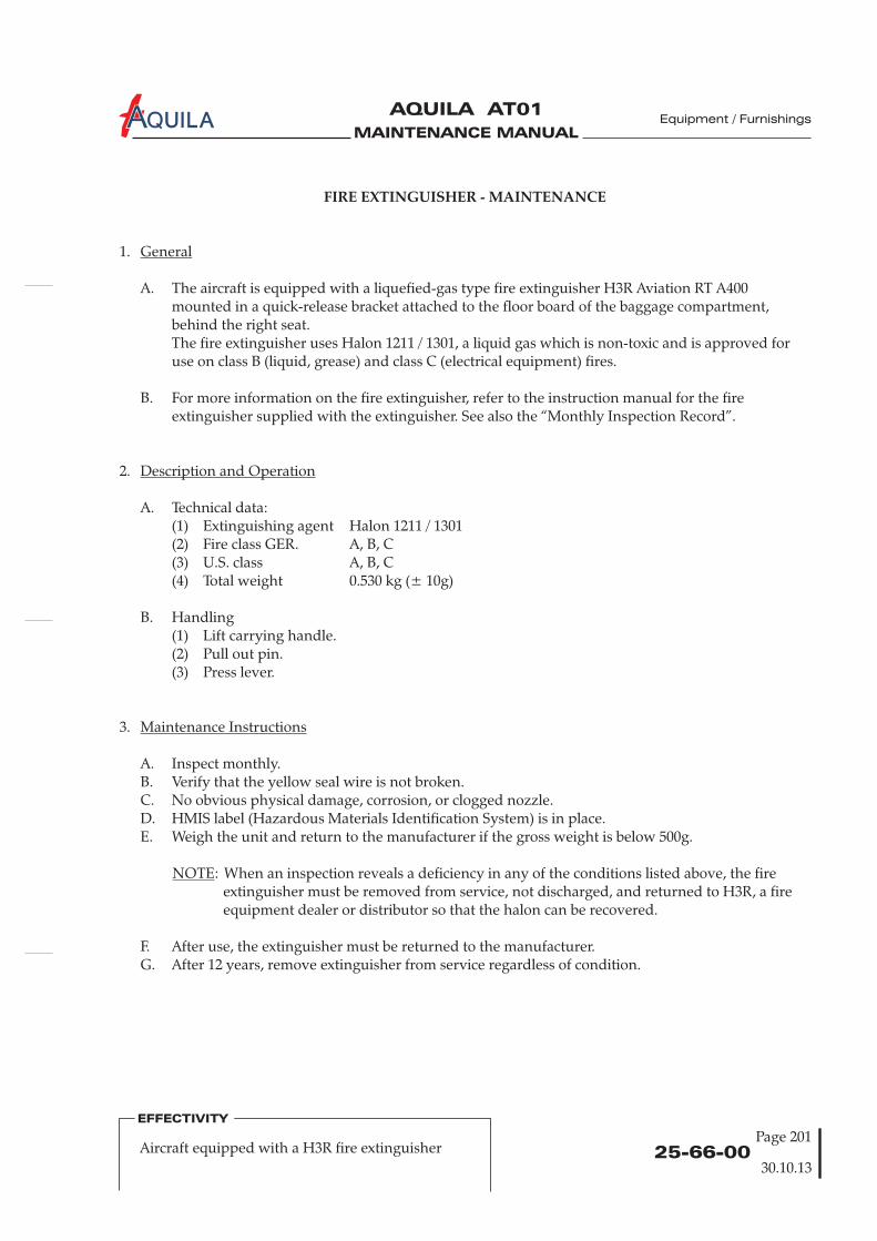
MAINTENANCE MANUAL
AQUILA AT01A
25-66-00
Page 201
FIRE EXTINGUISHER - MAINTENANCE
1.
A. The aircraft is equipped with a liquefied-gas type fire extinguisher H3R Aviation RT A400mounted in a quick-release bracket attached to the floor board of the baggage compartment,behind the right seat.The fire extinguisher uses Halon 1211 / 1301, a liquid gas which is non-toxic and is approved foruse on class B (liquid, grease) and class C (electrical equipment) fires.
B. For more information on the fire extinguisher, refer to the instruction manual for the fireextinguisher supplied with the extinguisher. See also the “Monthly Inspection Record”.
2.
A. Technical data:(1) Extinguishing agent Halon 1211 / 1301(2) Fire class GER. A, B, C(3) U.S. class(4) Total weight 0.530 kg (± 10g)
B. Handling(1) Lift carrying handle.(2) Pull out pin.(3) Press lever.
3.
A. Inspect monthly.B. Verify that the yellow seal wire is not broken.C. No obvious physical damage, corrosion, or clogged nozzle.D. HMIS label (Hazardous Materials Identification System) is in place.E. Weigh the unit and return to the manufacturer if the gross weight is below 500g.
: When an inspection reveals a deficiency in any of the conditions listed above, the fireextinguisher must be removed from service, not discharged, and returned to H3R, a fireequipment dealer or distributor so that the halon can be recovered.
F. After use, the extinguisher must be returned to the manufacturer.G. After 12 years, remove extinguisher from service regardless of condition.
General
Description and Operation
Maintenance Instructions
NOTE
A, B, C
Aircraft equipped with a H3R fire extinguisher
EFFECTIVITY
Equipment / Furnishings
30.10.13

MAINTENANCE MANUAL
AQUILA AT01A Equipment / Furnishings
Page 20225-66-00
30.10.13
4.
A. Remove Fire Extinguisher(1) Release quick-release clamp.(2) Remove fire extinguisher from bracket assembly.
B. Install Fire Extinguisher(1) Position fire extinguisher in bracket assembly.(2) Secure with quick release clamp.
Fire Extinguisher Removal/Installation
Aircraft equipped with a H3R fire extinguisher
EFFECTIVITY
MAINTENANCE MANUAL
AQUILA AT01A
CHAPTER 27
FLIGHT CONTROLS

MAINTENANCE MANUAL
AQUILA AT01A
MAINTENANCE MANUAL
AQUILA AT01A
Page 127 - TOC
Flight Controls
TABLE OF CONTENTS
ChapterSection
FLIGHT CONTROLS - GENERAL .................................................................27-00-00 1Introduction 27-00-00 1General Description 27-00-00 1
AILERON CONTROL SYSTEM - DESCRIPTION.......................................27-10-00 1Introduction 27-10-00 1Description and Operation 27-10-00 1
AILERON CONTROL SYSTEM - MAINTENANCE ...................................27-10-00 201General 27-10-00 201Control Stick Removal/Installation 27-10-00 201Pushrod 1 Removal/Installation 27-10-00 201Front Bellcrank Removal/Installation 27-10-00 201Pushrod 2 Removal/Installation 27-10-00 203Rear Bellcrank Removal/Installation 27-10-00 203Pushrod 3 Removal/Installation 27-10-00 203Pushrod 4 Removal/Installation 27-10-00 205Aileron Bellcrank Removal/Installation 27-10-00 205Inspection/Check 27-10-00 205Adjustment/Test 27-10-00 207
RUDDER CONTROL SYSTEM - DESCRIPTION........................................27-20-00 1Introduction 27-20-00 1Description and Operation 27-20-00 1
RUDDER CONTROL SYSTEM - MAINTENANCE.....................................27-20-00 201General 27-20-00 201Control Cables 27-20-00 201Rudder Pedal Assembly Removal/Installation 27-20-00 201Control Cable Removal/Installation 27-20-00 203Inspection/Check 27-20-00 203Adjustment/Test 27-20-00 203
ELEVATOR CONTROL SYSTEM - DESCRIPTION ....................................27-30-00 1Introduction 27-30-00 1Description and Operation 27-30-00 1
ELEVATOR CONTROL SYSTEM - MAINTENANCE.................................27-30-00 201General 27-30-00 201Elevator Torque Tube Assy Removal/Installation 27-30-00 201Pushrod 1 Removal/Installation 27-30-00 201Elevator Bellcrank Removal/Installation 27-30-00 203
Title Subject Page
30.10.13

MAINTENANCE MANUAL
AQUILA AT01A
27 - TOC
TABLE OF CONTENTS (Cont.)
ChapterSection
Title Subject Page
Flight Controls
Inspection/Check 27-30-00 203Adjustment/Test 27-30-00 203
ELEVATOR TRIM CONTROL - DESCRIPTION..........................................27-31-00 1Introduction 27-31-00 1Description and Operation 27-31-00 1
ELEVATOR TRIM CONTROL - MAINTENANCE ......................................27-31-00 201General 27-31-00 201Trim Actuator Removal/Installation 27-31-00 201Inspection/Check 27-31-00 201
FLAP CONTROL SYSTEM - DESCRIPTION ...............................................27-50-00 1Introduction 27-50-00 1Description and Operation 27-50-00 1
FLAP CONTROL SYSTEM - MAINTENANCE............................................27-50-00 201General 27-50-00 201Flap Actuator Assembly Removal/Installation 27-50-00 201Torque Tube Assembly Removal/Installation 27-50-00 201Flap Pushrod Removal/Installation 27-50-00 201Inspection/Check 27-50-00 203Adjustment/Test 27-50-00 206
30.10.13
Page 2
MAINTENANCE MANUAL
AQUILA AT01A
27-00-00
FLIGHT CONTROLS - GENERAL
1.
A. This chapter contains information about the flight controls used to manually control the aircraft inflight. It also includes functional and maintenance information about the flaps.
2.
A. The conventionally designed flight control system is divided into aileron control, rudder control,elevator control and the wing flaps system. The aircraft is equipped with dual controls.The control stick and rudder pedals are used for control input. Elevator trim can be actuatedelectrically. Aileron and elevator control motion is transferred to the control surfaces via pushrodsand bellcranks. The rudder control system utilizes control cables and bellcranks for rudderactuation. The flaps are operated and fixed in the desired position by an electrical flap actuator.
B. For dimensions, areas and free play tolerances of the control surfaces refer to 06-00-00.
Introduction
General Description
Flight Controls
30.10.13
Page 1

MAINTENANCE MANUAL
AQUILA AT01A
MAINTENANCE MANUAL
AQUILA AT01A
27-10-00
Flight Controls
AILERON CONTROL SYSTEM - DESCRIPTION
1.
A. This section describes that portion of the flight control system which controls the position andmovement of the ailerons. The rigging procedure for the aileron control system is also provided.The ailerons are actuated via pushrods and bellcranks. Each aileron has weight compensation.To correct the tendency to roll precisely, a ground-adjustable trim tab is provided at the leadingedge of the left aileron.
2.
A. For aileron control system design and function refer to figure 1.
Introduction
Description and Operation
30.10.13
Page 1

MAINTENANCE MANUAL
AQUILA AT01A
27-10-00
Aileron Control System Design and FunctionFigure 1
pushrod 4
pushrod 3
pushrod 1
pushrod 2
Flight Controls
30.10.13
Page 2

MAINTENANCE MANUAL
AQUILA AT01A
27-10-00
Page 201
Flight Controls
AILERON CONTROL SYSTEM - MAINTENANCE
WARNING: WHEN INSTALLING COMPONENTS OF CONTROL SYSTEM, NEW SELF-LOCKINGNUTS SHOULD ALWAYS BE USED. NEVER USE A SELF-LOCKING NUT MORE THANONCE.
A. For a breakdown of components, refer to figure 201, 202 and 203.
1.
2.
A. Remove Control Stick(1) Remove access panel 211 HL (HR) (refer to 25-12-00).(2) Disconnect electrical cable to the transmission button.(3) Disconnect pushrod at control stick base.(4) Remove bolt securing control stick to torque tube assembly and remove stick.
B. Install Control Stick(1) Position control stick and secure to torque tube assembly using bolt, washer and nut.(2) Connect pushrod to control stick base.(3) Reconnect electrical cable to the transmission button.(4) Install access panel 211 HL (HR) (refer to 25-12-00).
3.
A. Remove Pushrod 1(1) Remove access panel 211 HL (HR) (refer to 25-12-00).(2) Disconnect pushrod at control stick base.(3) Disconnect pushrod at front bell crank and remove pushrod.
B. Install Pushrod 1(1) Connect pushrod to front bellcrank and control stick base.(2) Perform aileron control system inspection/check (refer to “Inspection/Check” below).(3) Install access panel 211 HL (HR) (refer to 25-12-00).
4.
A. Remove Front Bellcrank(1) Remove access plate 210 AB (refer to 06-30-00).(2) Remove access panel 211 HL and 211 HR (refer to 25-12-00).(3) Disconnect pushrods at front bellcrank.(4) Remove pivot bolt securing bellcrank to bellcrank brackets and remove bellcrank.
General
Control Stick Removal/Installation
Pushrod Removal/Installation
Front Bellcrank Removal/Installation
30.10.13
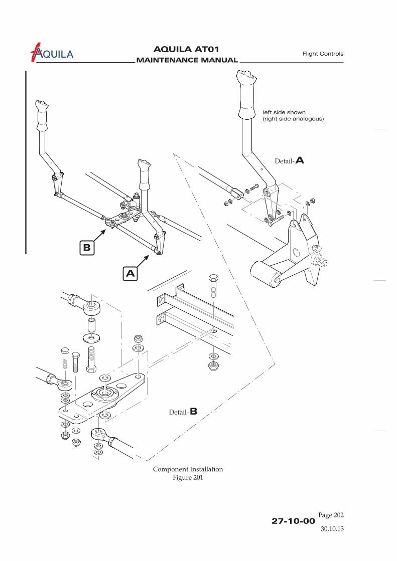
MAINTENANCE MANUAL
AQUILA AT01A
27-10-00Page 202
Component InstallationFigure 201
ADetail-
BDetail-
B
A
left side shown
(right side analogous)
Flight Controls
30.10.13

MAINTENANCE MANUAL
AQUILA AT01A
27-10-00
Page 203
Flight Controls
B. Install Front Bellcrank(1) Position front bellcrank between brackets and secure using bolt, washer and nut.(2) Connect pushrods to front bellcrank.(3) Perform aileron control system inspection/check ( ).(4) Install access plate 210 AB (refer to 06-30-00).(5) Install access panel 211 HL and 211 HR (refer to 25-12-00).
5.
A. Remove Pushrod 2(1) Remove access plate 210 AB (refer to 06-30-00).(2) Disconnect pushrod at front bellcrank.(3) Disconnect pushrod at rear bell crank and remove pushrod.
B. Install Pushrod 2(1) Connect pushrod to front bellcrank and rear bellcrank.(2) Perform aileron control system inspection/check ( ).(3) Install access plate 210 AB (refer to 06-30-00).
6.
A. Remove Rear Bellcrank(1) Remove access plate 210 AB (refer to 06-30-00).(2) Disconnect pushrods at rear bellcrank.(3) Remove nuts, washers and bellcrank axle securing bellcrank to bellcrank brackets and remove
bellcrank.
B. Install Rear Bellcrank(1) Position rear bellcrank between brackets and secure using axle, washers and nuts.(2) Attach pushrods to rear bellcrank.(3) Perform aileron control system inspection/check ( ).(4) Install access plate 210 AB (refer to 06-30-00).
7.
A. Remove Pushrod 3(1) Remove access plate 210 AB (refer to 06-30-00).(2) Disconnect pushrod at rear bellcrank.(3) Disconnect pushrod at pushrod 4.
B. Install Pushrod 3(1) Connect pushrod to rear bellcrank and pushrod 4.(2) Perform aileron control system inspection/check ( ).(3) Install access plate 210 AB (refer to 06-30-00).
refer to “Inspection/Check” below
refer to “Inspection/Check” below
refer to “Inspection/Check” below
refer to “Inspection/Check” below
Pushrod 2 Removal/Installation
Rear Bellcrank Removal/Installation
Pushrod 3 Removal/Installation
30.10.13

MAINTENANCE MANUAL
AQUILA AT01A
27-10-00Page 204
Component InstallationFigure 202
C
D
DDetail-
CDetail-
left side shown
(right side analogous)
Flight Controls
30.10.13

MAINTENANCE MANUAL
AQUILA AT01A
27-10-00
Page 205
Flight Controls
8.
A. Remove Pushrod 4(1) Remove wing (refer to 57-10-00).(2) Open access panel 520 (620) AB (refer to 06-30-00).(3) Disconnect pushrod at aileron bellcrank.(4) Remove rod end bearing.(5) Cautiously withdraw pushrod from wing.
B. Install Pushrod 4(1) Position pushrod into the wing.(2) Install rod end bearing.(3) Attach pushrod to aileron bellcrank.(4) Install wing (refer to 57-10-00).(5) Connect pushrod 4 to pushrod 3.(6) Re-rig aileron control system ( ).(7) Perform aileron control system inspection/check ( ).(8) Close access panel 520 (620) AB (refer to 06-30-00).
9.
A. Remove Aileron Bellcrank(1) Open access plate 520 (620) AB (refer to 06-30-00).(2) Disconnect pushrods at aileron bellcrank.(3) Remove pivot bolt securing bellcrank to bellcrank bracket assembly. Remove bellcrank and
washers through access plate.
B. Install Aileron Bellcrank(1) Attach bellcrank to structure using pivot bolt, ensuring required washers are in place.(2) Reconnect aileron pushrod to bellcrank.(4) Reconnect pushrod 4 to the bellcrank.(5) Perform aileron control system inspection/check ( ).(6) Close inspection/access plate 520 (620) AB (refer to 06-30-00).
10.
A. Inspection/Check(1) Perform a visual inspection of the aileron control system. Check all components for proper
installation and security. No signs of excessive play.
The maximum permissible value of aileron play at the hinge pins is 1,0 mm(0.04 in.) axial play and 0,3 mm (0.01 in.) radial play. The maximum control circuitbacklash is 10 mm (0.4 in.).In case of excessive play of the control surfaces in their hinges, replace worn hingebushings (refer also to 57-50-00).
Pushrod 4 Removal/Installation
Aileron Bellcrank Removal/Installation
Inspection/Check
NOTE:
refer to “Adjustment/Test” belowrefer to “Inspection/Check” below
refer to “Inspection/Check” below
30.10.13

MAINTENANCE MANUAL
AQUILA AT01A
27-10-00Page 206
Aileron Bellcrank InstallationFigure 203
E
F
FDetail-
EDetail-
left side shown
(right side analogous)
Flight Controls
30.10.13
MAINTENANCE MANUAL
AQUILA AT01A
27-10-00
Page 207
Flight Controls
(2) Verify minimum rod end thread engagement of 8 mm (0.312 in.).(3) Verify ailerons can be moved smoothly through the full travel. No grinding is audible.(4) Check ailerons for correct travel using an inclinometer. If necessary perform aileron control
system adjustment/test ( ).
For aileron rigging specifications, refer to chapter 6 „Dimensions and Areas“.
(5) Install all items removed for access.
11.
A. Adjustment/Test(1) Remove access plate 210 AB (refer to 06-30-00).(2) Remove access plate 620 AB and 520 AB (refer to 06-30-00).(3) Remove access plate 211 HL and HR (refer to 06-30-00).(4) Adjust pushrod 2 until:
(a) front and rear bellcrank are parallel to each other.(b) both bellcranks are perpendicular to the wing spar.
(5) Fix bellcranks in a suitable manner.(6) Adjust pushrod 3 for each aileron so the aileron bellcrank is in neutral position (line between
bellcrank pivot bolt and aileron pushrod attach bolt is parallel to the wing spar).(7) Adjust each aileron pushrod until the control surface is neutral with reference to wing trailing
edge.(8) Adjust pushrod 1 for each control stick until the control stick is in neutral position.(9) Set free the front and rear bellcrank.(10) Fasten inclinometer to left aileron and set at 0°.(11) Adjust aileron stop bolts at control yoke assembly to allow up and down aileron travel
specified in 06-10-00.(12) Perform an aileron control system inspection/check ( ).(13) Install all items removed for access.
refer to “Adjustment/Test” below
refer to “Inspection/Check” above
NOTE:
Adjustment/Test
30.10.13

MAINTENANCE MANUAL
AQUILA AT01A
MAINTENANCE MANUAL
AQUILA AT01A
27-20-00
RUDDER CONTROL SYSTEM - DESCRIPTION
1.
A. This section describes that portion of the flight control system which controls the position andmovement of the rudder. The rigging procedure for the rudder control system is also provided.The rudder control system consists of conventional rudder pedals, cables and pulleys.
2.
A. For rudder control system design and function refer to figure 1.
Introduction
Description and Operation
Flight Controls
30.10.13
Page 1

MAINTENANCE MANUAL
AQUILA AT01A
27-20-00
Rudder Control Design and FunctionFigure 1
Flight Controls
30.10.13
Page 2
MAINTENANCE MANUAL
AQUILA AT01A
27-20-00
Page 201
RUDDER CONTROL SYSTEM - MAINTENANCE
WARNING: WHEN INSTALLING COMPONENTS OF THE CONTROL SYSTEM, NEW SELF-LOCKING NUTS SHOULD ALWAYS BE USED. NEVER USE A SELF-LOCKING NUTMORE THAN ONCE.
A SYSTEM RIGGING AND INSPECTION/CHECK MUST BE PERFORMED AFTERLOOSENING ANY FLIGHT CONTROL CABLE TO ENSURE PROPER CONTROLSURFACE OPERATION.
1.
A. For a breakdown of the components, refer to figure 201 and 202.
2.
A. The maintenance of the control cables is important for the precise and safe functioning of therudder control system. Control cables should be regularly checked for mechanical damage anddamage caused by corrosion.
(1)Check cables for broken strands of wire by passing a cloth along length of cable. The clothwill snag at such places. If broken wires are found, the affected control cable must beexamined in more detail and removed if necessary. If a broken single wire is found, thecontrol cable must be replaced. The procedures for control cable removal and installation aredescribed below.
(2)External corrosion can be detected by a careful visual examination of the cables. Findinginternal corrosion is more difficult. If internal corrosion is suspected, remove cable from theaircraft and examine more closely, especially in areas with broken wires.
3.
A. Remove Rudder Pedal Assembly(1) Slacken control cables of rudder control.(2) Disconnect control cables from rudder control actuator arms.(4) Disconnect brake master cylinders at rudder pedal assembly.(5) Disconnect steering tubes at rudder bars.(6) Remove bolts securing lower half of the middle bearing block to upper half and remove
lower bearing block half.(7) Remove bolts attaching left and right bearing blocks to firewall and work rudder bars out of
area below instrument panel.
B. Install Rudder Pedal Assembly(1) Position rudder bars in left and right bearing blocks and secure bearing blocks to firewall
using bolts.
General
Control Cables
Broken Wire Check
Corrosion Check
Rudder Pedal Assembly Removal/Installation
Flight Controls
30.10.13

MAINTENANCE MANUAL
AQUILA AT01A
27-20-00Page 202
Rudder Control InstallationFigure 201
ADetail-
A
Flight Controls
30.10.13

MAINTENANCE MANUAL
AQUILA AT01A
27-20-00
Page 203
(2) Reinstall lower half of middle bearing block.(3) Reconnect steering tubes to rudder bars.(4) Reconnect master cylinders to the rudder pedal assembly.(5) Reconnect control cables to rudder control actuator arms and re-rig system (refer to
“Adjustment/Test“ below).(6) Check correct operation of the rudder control system (refer to “Inspection/Check” below).
4.
A. Remove a Control Cable(1) Relieve cable tension at turnbuckle.(2) Disconnect control cable at the turnbuckle.(3) Disconnect control cable at the rudder.(4) Cut the eye-end from the control cable which is to be removed at the turnbuckle end.(5) Withdraw control cable from the aircraft.
B. Install a Control Cable
THE CONTROL CABLE EYE-ENDS SHOULD BE INSTALLED BY TRAINEDAND AUTHORIZED PERSONNEL ONLY. IF THE EYE-ENDS ARE NOTINSTALLED PROPERLY; A RUDDER CONTROL SYSTEM FAILURE MAYOCCUR.USE CABLES TO SPECIFICATION LN9374 OR ISO 2020 OR MIL-DTL-83420,STRECHED TO 60% MBS (DIAMETER 3,2 MM [1/8 IN.]).
(1) Prepare a new control cable with the required length and one eye-end.(2) Push that control cable through the tube from the rudder side.(3) Install the second eye-end at the turnbuckle end.(4) Reconnect the control cable to the rudder using bolt, washer and nut.(5) Reconnect the control cable to the turnbuckle using bolt , washer and nut.(6) Rig rudder control cable including cables of the aileron-rudder interconnect and check
correct operation of rudder control system / aileron-rudder interconnect (refer to“Adjustment/Test“ and “Inspection/Check” below).
Control Cable Removal/Installation
WARNING:
Flight Controls
5.
A. Inspection/Check(1) Perform a visual inspection of the rudder control system. Check all components for proper
installation and security. No signs of excessive play.
The maximum permissible value of rudder play at hinge pins is 1,0 mm (0.04 in.)axial play and 0,3 mm (0.01 in.) radial play.In case of excessive play of the control surface in its hinges, replace worn hingebushings (refer also to 57-50-00).
(2) Examine control cables for broken wires and corrosion.
Inspection/Check
NOTE:
30.10.13

MAINTENANCE MANUAL
AQUILA AT01A
Rudder Pedal / Master Cylinder InstallationFigure 202
27-20-00Page 204
Flight Controls
30.10.13
ADetail-
A

MAINTENANCE MANUAL
AQUILA AT01A
(3) Verify rudder can be moved smoothly through full travel. No grinding is audible.(4) Check rudder for correct travel using an inclinometer, if necessary perform rudder control
system adjustment/test (refer to “Adjustment/Test” below).
For rudder rigging specifications, refer to chapter 6 “Dimensions and Areas“.
(5) Install all items removed for access.
6.
A. Adjustment/Test(1) Remove engine cowling (refer to 71-10-00).(2) Slacken control cables of rudder control.(3) Tie down or weight tail to raise nose wheel off the ground.(4) Set the rudder pedals to neutral and fix in suitable manner.(5) Fix the rudder in neutral position with reference to vertical stabilizer.(6) Tension the control cables with the turnbuckles until the control system is free of clearance at
room temperature.(7) Adjust nose wheel steering tubes so the nose wheel is streamlined.(8) Set the rudder control system free.(9) Adjust secondary stops on the nose wheel strut so that for full right and left rudder
deflection:(a) the rudder stops contact before secondary stops.(b) secondary stops show a 0,5 mm (0.02 in.) gap between stop bolt and nose wheel
assembly.(10) Tighten jam nuts.(11) Verify rudder pedals are free for the full range of movement.(12) Perform a rudder control system inspection/check (refer to “Inspection/Check” above).(13) Install engine cowling (refer to 71-10-00) and lower nose wheel.
NOTE:
Adjustment/Test
27-20-00
Page 205
Flight Controls
30.10.13

MAINTENANCE MANUAL
AQUILA AT01A
MAINTENANCE MANUAL
AQUILA AT01A
27-30-00
ELEVATOR CONTROL SYSTEM - DESCRIPTION
1.
A. This section describes that portion of the flight control system which controls the position andmovement of the elevator. The rigging procedure for the elevator control system is also provided.The system consists of control sticks, elevator torque tube assembly, pushrods and the elevatorbellcrank.The aircraft is equipped with an electrical spring-force elevator trim system.
2.
A. For elevator control system design and function refer to figure 1.
Introduction
Description and Operation
Flight Controls
30.10.13
Page 1
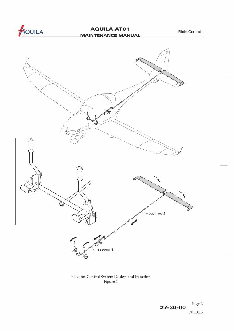
MAINTENANCE MANUAL
AQUILA AT01A
27-30-00
Elevator Control System Design and FunctionFigure 1
Flight Controls
pushrod 1
pushrod 2
30.10.13
Page 2

MAINTENANCE MANUAL
AQUILA AT01A
27-30-00
Page 201
ELEVATOR CONTROL SYSTEM - MAINTENANCE
WARNING: WHEN INSTALLING COMPONENTS OF THE CONTROL SYSTEM NEW SELF-LOCKING NUTS SHOULD ALWAYS BE USED. NEVER USE A SELF-LOCKING NUTMORE THAN ONCE.
1.
A. For a breakdown of the components, refer to figure 201 and 202.
2.
A. Remove Elevator Torque Tube Assy(1) Remove seats (refer to 25-10-00).(2) Remove control sticks (refer to 27-10-00).(3) Disconnect pushrod 1 from elevator actuation arm.(4) Remove pivot bolt, washers and nut from both ends of the torque tube with which the torque
tube is attached to the support bracket.(5) Remove torque tube from aircraft.
B. Install Elevator Torque Tube Assy(1) Position torque tube between support brackets.(2) Attach pivot bolt, washers and nut to both ends of the torque tube with which the torque
tube is attached to the support bracket.(3) Connect pushrod 1 to elevator actuation arm.(4) Install control sticks (refer to 27-10-00).(5) Check elevator and aileron control for proper operation and rig if necessary (refer to “Aileron
Control System Maintenance“ and „Adjustment/Test“ below).
3.
A. Remove Pushrod 1(1) Remove seats (refer to 25-10-00).(2) Remove baggage compartment floor panel (refer to 25-12-00).(3) Disconnect trim system springs from pushrod.(4) Disconnect pushrod at elevator actuation arm.(5) Disconnect pushrod at elevator bellcrank.(6) Remove pushrod from aircraft.
B. Install Pushrod 1(1) Position pushrod and connect to elevator bellcrank.(2) Connect pushrod to elevator actuation arm.(3) Connect springs of trim system to pushrod.
If spring attachment clamps have been removed, refer to 27-31-00 for their correctposition.
General
Elevator Torque Tube Assy Removal/Installation
Pushrod 1 Removal/Installation
NOTE:
Flight Controls
30.10.13

MAINTENANCE MANUAL
AQUILA AT01A
27-30-00Page 202
Component InstallationFigure 201
AB
ADetail-
BDetail-
left side shown
(right side analogous)
Flight Controls
Fuselage structure
omitted for clarity.
30.10.13
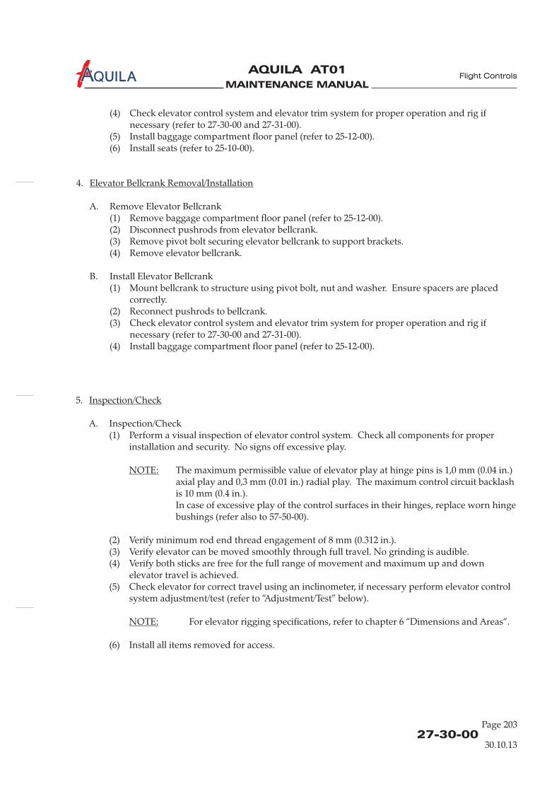
MAINTENANCE MANUAL
AQUILA AT01A
27-30-00
Page 203
(4) Check elevator control system and elevator trim system for proper operation and rig ifnecessary (refer to 27-30-00 and 27-31-00).
(5) Install baggage compartment floor panel (refer to 25-12-00).(6) Install seats (refer to 25-10-00).
4.
A. Remove Elevator Bellcrank(1) Remove baggage compartment floor panel (refer to 25-12-00).(2) Disconnect pushrods from elevator bellcrank.(3) Remove pivot bolt securing elevator bellcrank to support brackets.(4) Remove elevator bellcrank.
B. Install Elevator Bellcrank(1) Mount bellcrank to structure using pivot bolt, nut and washer. Ensure spacers are placed
correctly.(2) Reconnect pushrods to bellcrank.(3) Check elevator control system and elevator trim system for proper operation and rig if
necessary (refer to 27-30-00 and 27-31-00).(4) Install baggage compartment floor panel (refer to 25-12-00).
Elevator Bellcrank Removal/Installation
Flight Controls
5.
A. Inspection/Check(1) Perform a visual inspection of elevator control system. Check all components for proper
installation and security. No signs off excessive play.
The maximum permissible value of elevator play at hinge pins is 1,0 mm (0.04 in.)axial play and 0,3 mm (0.01 in.) radial play. The maximum control circuit backlashis 10 mm (0.4 in.).In case of excessive play of the control surfaces in their hinges, replace worn hingebushings (refer also to 57-50-00).
(2) Verify minimum rod end thread engagement of 8 mm (0.312 in.).(3) Verify elevator can be moved smoothly through full travel. No grinding is audible.(4) Verify both sticks are free for the full range of movement and maximum up and down
elevator travel is achieved.(5) Check elevator for correct travel using an inclinometer, if necessary perform elevator control
system adjustment/test (refer to “Adjustment/Test” below).
For elevator rigging specifications, refer to chapter 6 “Dimensions and Areas“.
(6) Install all items removed for access.
Inspection/Check
NOTE:
NOTE:
30.10.13

MAINTENANCE MANUAL
AQUILA AT01A
27-30-00Page 204
Component InstallationFigure 202
ADetail-
BDetail-
A
B
Flight Controls
Fuselage structure
omitted for clarity.
30.10.13

MAINTENANCE MANUAL
AQUILA AT01A
27-30-00
Page 205
Flight Controls
6.
A. Adjustment/Test(1) Remove baggage compartment floor panel (refer to 25-12-00).(2) Remove access plate 211 HL and HR (refer to 25-12-00).(3) Lock elevator bellcrank in neutral position in a suitable manner (the line between pushrod
attach points on bellcrank is perpendicular to the pushrod 2).(4) Streamline elevator to neutral with horizontal stabilizer by adjusting elevator pushrod
(pushrod 2).(5) Adjust pushrod 1 until the control yoke assembly is in neutral position.
Adjustment/Test
30.10.13

MAINTENANCE MANUAL
AQUILA AT01A

MAINTENANCE MANUAL
AQUILA AT01A
27-31-00
Flight Controls
ELEVATOR TRIM CONTROL - DESCRIPTION
1.
A. The aircraft isequipped with an electrical spring-force trim system. An electrical trim actuatorchanges the pre-load of a pair of springs that applies a defined force to the elevator pushrod.
2.
A. For an illustration of elevator trim control design and function refer to figure 1.
B. The trim system is controlled by a rocker switch located on the rear portion of the middle console.Pressing the forward side of the switch will trim nose down; pressing the rear side of the switchwill trim nose up.The switch operates an electrical trim actuator that is mounted under the baggage compartmentfloor panel, parallel to the elevator pushrod.The electrical circuit of the trim system is protected by a circuit breaker that can be pulled in theevent of a trim system malfunction.
Introduction
Description and Operation
30.10.13
Page 1
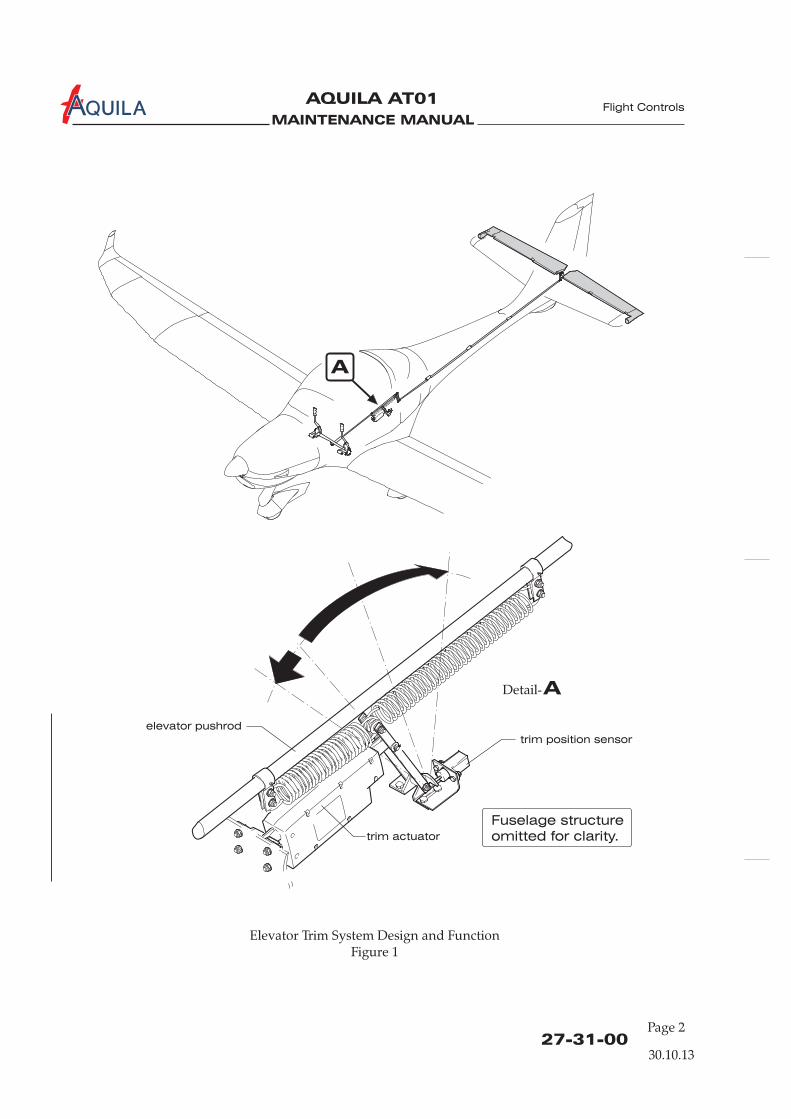
MAINTENANCE MANUAL
AQUILA AT01A
ADetail-
elevator pushrod
trim actuator
Elevator Trim System Design and FunctionFigure 1
27-31-00
Flight Controls
Fuselage structure
omitted for clarity.
trim position sensor
30.10.13
A
Page 2

MAINTENANCE MANUAL
AQUILA AT01A Flight Controls
27-31-00
Page 201
ELEVATOR TRIM CONTROL - MAINTENANCE
1.
A. For a breakdown of the components, refer to figure 201.
2.
A. Remove Trim Actuator(1) Set the elevator trim system to neutral.(2) Ensure electrical power to aircraft is OFF.(3) Remove baggage compartment floor panel (refer to 25-12-00).(4) Disconnect trim actuator electrical wires at connector.(5) Disconnect the springs at trim system actuation arm.(6) Disconnect trim actuator push rod at trim system actuation arm.(7) Remove bolts securing trim actuator to fuselage structure and remove trim actuator from
aircraft.
B. Install Trim Actuator(1) Attach trim actuator to fuselage structure with bolts, washers and nuts.(2) Reconnect trim actuator push rod to trim system actuation arm using hardware.(3) Reconnect springs to trim system actuation arm.
(4) Connect trim actuator electrical connection.(5) Check for proper function (refer to “Inspection/Check” below).(6) Install baggage compartment floor panel (refer to 25-12-00).
3.
A. Inspection/Check(1) Perform a visual inspection of elevator trim system. Check all components for proper
installation and security. No signs off excessive play.(2) Place BAT switch in ON position.(3) Keep hands away from control stick and run trim actuator to full nose-down trim position
until travel is stopped by limit switch.(4) Check the forward movement of the control stick. Verify the proper trim position indicator
reading.(5) Keep hands away from control stick and run trim actuator to full nose-up trim position until
travel is stopped by limit switch.(6) Check the backward movement of the control stick. Verify the proper trim position indicator
reading.(7) Set the elevator trim to neutral and place BAT switch in OFF position.(8) Install all items removed for access.
General
Trim Actuator Removal/Installation
Inspection/Check
NOTE: There are two different types of springs used in the trim system. The spring onthe forward side is black colored, the spring on the rear side is silver colored.
elevator trim control
30.10.13

MAINTENANCE MANUAL
AQUILA AT01A
27-31-00Page 202
Elevator Trim System InstallationFigure 201
Flight Controls
Fuselage structure
omitted for clarity.
Fuselage structure
omitted for clarity.
ADetail-
30.10.13
A
MAINTENANCE MANUAL
AQUILA AT01A
FLAP CONTROL SYSTEM - DESCRIPTION
1.
A. This section describes that portion of the flight control system which controls the position andmovement of the flaps. The rigging procedure forthe flap control system is also provided.The aircraft is equipped with electrically actuated flaps. They are operated and fixed in thedesired position by an electrical flap actuator.
2.
A. The wing flaps system consists of a three-position selector switch which is incorporated in theinstrument panel, a LED flap position indicator near the three-position selector switch, the electricflap actuator, located under the baggage floor, a torque tube, pushrods and the flaps on each wing.
B. The linear flap actuator drives the torque tube interconnected between the left and right flaps.Limit switches are attached to the flap actuator. They identify flap position and surface travel, andturn off the actuator once the desired position is reached, i.e: 17° or 35°.The flap actuator has a slip coupling to prevent mechanical damage if a restriction occurs. In theevent of a failure in the electric flap control circuit, torque tube/actuator geometry prevents theflaps from causing an uncontrollable flight condition.
C. For an illustration of flap control system design and function refer to figure 1.
Introduction
Description and Operation
27-50-00
Flight Controls
30.10.13
Page 1
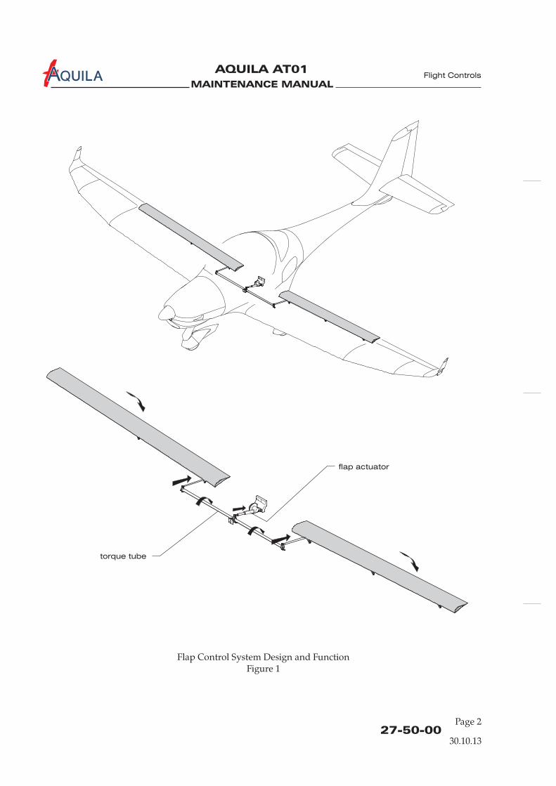
MAINTENANCE MANUAL
AQUILA AT01A
flap actuator
torque tube
Flap Control System Design and FunctionFigure 1
27-50-00Page 2
Flight Controls
30.10.13

MAINTENANCE MANUAL
AQUILA AT01A Flight Controls
27-50-00
Page 201
FLAP CONTROL SYSTEM - MAINTENANCE
1.
A. This section provides instructions for removal and installation of components and instruction forflap control system rigging.
B. For a breakdown of the components, refer to figure 201, 202, 203, and 204.
2.
A. Remove Flap Actuator Assembly(1) Ensure electrical power to aircraft is OFF.(2) Remove baggage compartment floor panel (refer to 25-12-00).(3) Disconnect flap actuator electrical wires at connector.(4) Disconnect flap actuator from torque tube coupler.(5) Remove nut, bolt and washers securing the flap actuator assembly to the actuator bracket and
remove flap actuator assembly from aircraft.
B. Install Flap Actuator Assembly(1) Place flap actuator assembly in the actuator bracket and attach using washers and bolt.(2) Attach washers, bolt and nut securing the flap actuator pushrod to the torque tube coupler.(3) Connect flap actuator electrical wires at connector.(4) Perform flap control system inspection/check and rig system, if necessary (refer to
“Inspection/Test” and “Adjustment/Test” below).(5) Install baggage compartment floor panel (refer to 25-12-00).
3.
A. Remove Torque Tube Assembly(1) Remove access plate 210 AB (refer to 06-30-00).(2) Remove access plate 610 AB and 510 AB (refer to 06-30-00).(3) Disconnect flap pushrod from torque tube assembly at each flap.(4) Disconnect flap actuator pushrod from torque tube assembly.(5) Remove bolt connecting torque tube halves.(6) Remove bolt securing torque tube halves to pivot bracket.(7) Withdraw right and left torque tube halves from inside the wing.
B. Install Torque Tube Assembly(1) Position torque tube halves inserting pivot pin located at outer end into the bearing inside the
wing.
ENSURE THE LONG EDGE OF THE COUPLER IS FACING TOWARDS THEWING SPAR.
(2) Secure both halves to pivot bracket using bolt, washer and nut.
General
Flap Actuator Assembly Removal/Installation
Torque Tube Assembly Removal/Installation
CAUTION:
30.10.13

MAINTENANCE MANUAL
AQUILA AT01A
27-50-00Page 202
Flight Controls
ADetail-
A
Flap Control System InstallationFigure 201
Fuselage structure
omitted for clarity.
30.10.13

MAINTENANCE MANUAL
AQUILA AT01A
27-50-00
Page 203
Flight Controls
(3) Install spacer and bolt, washer and nut connecting halves.(4) Connect torque tube assembly to flap actuator pushrod.(5) Perform flap control system inspection/check and rig system, if necessary (refer to
“Inspection/Check” and “Adjustment/Test” below).
4.
Left and right flap pushrod removal/installation is analogous.
A. Remove Flap Pushrod(1) Remove wing access plate 610 AB (510 AB)(refer to 06-30-00).
WHEN DISCONNECTING FLAP PUSHROD FROM FLAP HORN, EXERCISECAUTION TO PREVENT THE FLAP FROM INADVERTENT SWINGINGDOWNWARD.
(2) Supporting the flap, disconnect flap pushrod at the flap horn.(3) Disconnect flap pushrod from torque tube assembly and remove pushrod from wing.
B. Install Flap Pushrod(1) Position and connect flap pushrod to torque tube assembly.(2) Connect flap pushrod at flap horn.(3) Re-rig flap control system and perform inspection/check (refer to “Inspection/Check” and
“Adjustment/Test” below).(4) Install all items removed for access.
5.
A. Inspection/Check(1) Prepare inspection.
(a) Remove baggage compartment floor panel.(b) Remove fuselage access panel 210 AB (refer to 06-30-00).(c) Remove access panel 610 AB and 510 AB (refer to 06-30-00).
(2) Inspect flap control system visually.(a) Verify proper installation and safetying of all items in the entire flap control system.(b) Check electrical connections.(c) Examine limit switches for security and condition.(d) Verify minimum rod end thread engagement of 8 mm (0.312 in.).(e) Verify no excessive play of control surfaces at hinge pins. Check the control circuit
backlash.
The maximum permissible value of control surface play at hinge pins is 1,0 mm(0.04 in.) axial play and 0,3 mm (0.01 in.) radial play. The maximum control circuitbacklash is 5 mm (0.2 in.).In case of excessive play of the control surfaces in their hinges, replace worn hingebushings (refer also to 57-50-00).
Flap Pushrod Removal/Installation
NOTE:
CAUTION!
Inspection/Check
NOTE:
30.10.13

MAINTENANCE MANUAL
AQUILA AT01A
27-50-00Page 204
Flight Controls
A
Flap Control System InstallationFigure 201
Wing structure
omitted for clarity.
ADetail-
30.10.13

MAINTENANCE MANUAL
AQUILA AT01A
(3) Perform operational check of the flap control system.(a) Operate flaps through their full range of travel, observing for uneven travel or jumpy
motion and binding.(b) Check correct flap full UP position. Rig if necessary (refer to “Adjustment/Test” below).(c) With flap full UP, fasten an inclinometer to inboard side of left flap and set to 0°.(d) Lower flap to T/O and then to LDG positions and check flap angles as specified in
06-10-00.(e) Repeat check on right flap.
If the results of inspection do not fall within the tolerance specified in 06-10-00,contact AQUILA Aviation GmbH for disposition.
(4) Install all items removed for access.
6.
A. Adjustment/Test(1) Remove access plate 210 AB (refer to 06-30-00).(2) With BAT switch in ON position turn flap control switch to CRUISE.(3) Turn BAT switch OFF.(4) Adjust push rod at flap actuator so that the flap torque tube assembly is in neutral position
(refer to figure 201).(5) Adjust pushrods at each flap until the control surfaces are neutral with reference to wing
trailing edge at root area.(6) Perform an flap control system inspection/check (refer to “Inspection/Check” above).(7) Install all items removed for access.
NOTE:
Adjustment/Test
27-50-00
Page 205
Flight Controls
30.10.13

MAINTENANCE MANUAL
AQUILA AT01A

MAINTENANCE MANUAL
AQUILA AT01A
CHAPTER 31
INDICATING / RECORDING SYSTEMS

MAINTENANCE MANUAL
AQUILA AT01A

MAINTENANCE MANUAL
AQUILA AT01A
Page 131 - TOC
Indicating / Recording
TABLE OF CONTENTS
ChapterSection
INDICATING / RECORDING SYSTEMS - GENERAL..................................31-00-00 1 Analog instr.Introduction 31-00-00 1General Description 31-00-00 1
INDICATING / RECORDING SYSTEMS - GENERAL..................................31-00-00 1Introduction 31-00-00 1General Description 31-00-00 1
INDICATING / RECORDING SYSTEMS - GENERAL..................................31-00-00 1Introduction 31-00-00 1General Description 31-00-00 1
INSTRUMENT PANEL - MAINTENANCE.....................................................31-10-00 201General 31-10-00 201Glare Shield Removal/Installation 31-10-00 201Instrument Panel Removal/Installation 31-10-00 201
Title Subject Page Effectivity
Analog instr.Analog instr.
Aspen EFD1000Aspen EFD1000Aspen EFD1000
Garmin G500Garmin G500Garmin G500
RECORDERS - MAINTENANCE ...................................................................31-30-00 201 KAPI systemGeneral 31-30-00 201 KAPI systemKAPI Unit Removal/Installation 31-30-00 203 KAPI systemKAPI GPS/GSM Antenna Removal/Installation 31-30-00 203 KAPI systemKAPI Airspeed Sensor Removal/Installation 31-30-00 204 KAPI systemKAPI G-Sensor Removal/Installation 31-30-00 204 KAPI system
30.10.13

MAINTENANCE MANUAL
AQUILA AT01A

MAINTENANCE MANUAL
AQUILA AT01A
31-00-00
Page 1
INDICATING / RECORDING SYSTEMS - GENERAL
1.
A.
2.
A. For easy and quick reference, the instruments and controls are clearly divided in groups.The group of flight instruments is directly in front of the pilot. Below the flight instruments is arow of switches. The middle section of the panel contains the avionics equipment including theNAV/COM transceiver and the transponder. O
p of instrumentsfor monitoring engine and system conditions is located below. These gauges show the fuel level ineach tank, cylinder head temperature, oil temperature, oil pressure as well as amperes and volts ofthe electrical system. The circuit breaker panel is located in front of the co-pilot.
B. A center console contains the control knobs for the carburetor heat, the choke, cabin heating, thethrottle and rpm control levers, the fuel selector / shut-off valve, the parking brake control knob,and the trim control switch.
C. The description, function and maintenance of the several specific instruments is contained in theappropriate section of this manual.
D. For an overview of the position of the various instruments, devices and controls on the instrumentpanel and center pedestal, refer to figure 1.
Introduction
General Description
Basically the instruments and avionic equipment can be chosen by the customer, but it cannot beinstalled in any arbitrary combination. Before removing or installing equipment the airplanemanufacturer AQUILA must be contacted, with the exception of replacing a unit by an identicalone.
n the right side of the avionics column the powergauges, the tachometer and the manifold pressure indicator, are mounted. A grou
Indicating / Recording
30.10.13
EFFECTIVITY
Aircraft equipped with analog instruments

MAINTENANCE MANUAL
AQUILA AT01A
31-00-00Page 2
Instrument Panel Basic Configuration for Day & Night VFRFigure 1
Indicating / Recording
30.10.13
Note: Arrangement of instruments may be different due to varying equipment.
EFFECTIVITY
Aircraft equipped with analog instruments
12345
12
Airspeed indicatorAttitude gyroAltimeterTurn coordinatorDirectional gyro
6 Vertical speed indicator7 Ignition switch8 ALT / BAT switch9 Electrical fuel pump switch10 Avionic master switch11 NAV light switch
Anti-collision light switch13 Landing light switch14 Instrument light switch15 Pitot heat switch (optional)
20 Flap control switch / indicator21 Elevator trim position indicator22 Magnetic compass23 Warning lights24 ELT remote control (optional)
25 Dimmer (Night-VFR)26 COM/NAV27 Transponder28 Manifold pressure indicator29 Tachometer30 Fuel level indicator31 CHT indicator32 Voltmeter33 Oil temperature indicator34 Ammeter35 Oil pressure indicator36 Circuit breaker panel37 Fresh air ventilator
Carburetor heat controlCabin heat controlChoke controlThrottle leverPropeller control leverElevator trim switchFuel selector / shut-off valveParking brake control lever
3839404142434445
2221 23 24 25
262928
1 2 3
30
27
31
4 5 6 32 3336
37
8
97
10
11
12
13
14
15
20 37
38
4039
41 42
43
45
44
34 35
MAINTENANCE MANUAL
AQUILA AT01A
INDICATING / RECORDING SYSTEMS - GENERAL
1.
A. Basically the instrument and avionic equipment can be chosen by the customer, but it cannot beinstalled in any arbitrary combination. Before removing or installing equipment the airplanemanufacturer AQUILA must be contacted, with the exception of replacing a unit by an identicalone.
2.
A.
B.
C.
Introduction
General Description
For easy and quick reference, the instruments and controls are clearly divided in groups.The Aspen EFD1000 PFD as the primary flight display is directly in front of the pilot. The back-upattitude indicator for Night-VFR is installed close to the Aspen EFD1000 PFD. Below the AspenEFD1000 PFD is a row of switches. The middle section of the panel contains the avionicsequipment including the NAV/COM transceiver and the transponder. On the right side of theavionics column the power gauges, the tachometer and the manifold pressure indicator, aremounted. A group of instruments for monitoring engine and system conditions is located below.These gauges show the fuel level in each tank, cylinder head temperature, oil temperature, oilpressure as well as amperes and volts of the electrical system. The circuit breaker panel is locatedin front of the co-pilot.
A center console contains the control knobs for the carburetor heat, the choke, cabin heating, thethrottle and rpm control levers, the fuel selector / shut-off valve, the parking brake control knob,and the trim control switch.
The description, function and maintenance of the several specific instruments is contained in theappropriate section of this manual.
D. For an overview of the position of the various instruments, devices and controls on the instrumentpanel and center pedestal, refer to figure 1.
31-00-00
Indicating / Recording
30.10.13
EFFECTIVITY
Aircraft equipped with Aspen EFD1000 PFDPage 1

MAINTENANCE MANUAL
AQUILA AT01A
31-00-00
Indicating / Recording
30.10.13
EFFECTIVITY
Instrument Panel Basic Configuration for Day & Night VFRFigure 1
Page 2Aircraft equipped with Aspen EFD1000 PFD
Note: Arrangement of instruments may be different due to varying equipment.
12
9
Aspen EFD1000 PFDAttitude gyro (Night-VFR)
3 Ignition switch4 ALT / BAT switch5 Electrical fuel pump switch6 PFD switch7 Avionic master switch8 NAV light switch
Anti-collision light switch10 Landing light switch11 Instrument light switch
20 Flap control switch / indicator21 Elevator trim position indicator22 Magnetic compass23 Warning lights24 ELT remote control (optional)25 Dimmer (Night-VFR)26 COM/NAV
27 Transponder28 Manifold pressure indicator29 Tachometer30 Fuel level indicator31 CHT indicator32 Voltmeter33 Oil temperature indicator34 Ammeter35 Oil pressure indicator36 Circuit breaker panel37 Fresh air ventilator
Carburetor heat controlCabin heat controlChoke controlThrottle leverPropeller control leverElevator trim switchFuel selector / shut-off valveParking brake control lever
3839404142434445
2221 23 24 25
262928
1
2
30
27
31
32 3336
37
4
53
6
7
8
9
10
11
20 37
38
4039
41 42
43
45
44
34 35

MAINTENANCE MANUAL
AQUILA AT01A
INDICATING / RECORDING SYSTEMS - GENERAL
1.
A. Basically the instrument and avionic equipment can be chosen by the customer, but it cannot beinstalled in any arbitrary combination. Before removing or installing equipment the airplanemanufacturer AQUILA must be contacted, with the exception of replacing a unit by an identicalone.
2.
A. For easy and quick reference, the instruments and controls are clearly divided in groups.The Garmin G500 as the primary flight display is directly in front of the pilot. The back-up attitudeindicator for Night-VFR is installed close to the Garmin G500.
B.
C.
Introduction
General Description
Below the G500 is a row of switches.The middle section of the panel contains the avionics equipment including the NAV/COMtransceiver and the transponder. On the right side of the avionics column the power gauges, thetachometer and the manifold pressure indicator, are mounted. A group of instruments formonitoring engine and system conditions is located below. These gauges show the fuel level ineach tank, cylinder head temperature, oil temperature, oil pressure as well as amperes and volts ofthe electrical system. The circuit breaker panel is located in front of the co-pilot.
A center console contains the control knobs for the carburetor heat, the choke, cabin heating, thethrottle and rpm control levers, the fuel selector / shut-off valve, the parking brake control knob,and the trim control switch.
The description, function and maintenance of the several specific instruments is contained in theappropriate section of this manual.
D. For an overview of the position of the various instruments, devices and controls on the instrumentpanel and center pedestal, refer to figure 1.
31-00-00
Indicating / Recording
30.10.13
EFFECTIVITY
Aircraft equipped with Garmin G500 PFD/MFDPage 1

MAINTENANCE MANUAL
AQUILA AT01A
EFFECTIVITY
31-00-0030.10.13
EFFECTIVITY
Instrument Panel Basic Configuration for Day & Night VFRFigure 1
Page 2Aircraft equipped with Garmin G500 PFD/MFD
Note: Arrangement of instruments may be different due to varying equipment.
Indicating / Recording
1
12
8
Garmin G500 PFD/MFDAttitude gyro (Night-VFR)
3 Ignition switch4 ALT / BAT switch5 Electrical fuel pump switch6 Avionic master switch7 NAV light switch
Anti-collision light switch09 Landing light switch10 Instrument light switch11 Pitot heat switch
20 Flap control switch / indicator21 Elevator trim position indicator22 Magnetic compass23 Warning lights24 ELT remote control (optional)25 Dimmer (Night-VFR)26 COM/NAV
27 Transponder28 Manifold pressure indicator29 Tachometer30 Fuel level indicator31 CHT indicator32 Voltmeter33 Oil temperature indicator34 Ammeter35 Oil pressure indicator36 Circuit breaker panel37 Fresh air ventilator
Carburetor heat controlCabin heat controlChoke controlThrottle leverPropeller control leverElevator trim switchFuel selector / shut-off valveParking brake control lever
3839404142434445
2221 23 24 25
262928
2
30
27
31
32 3336
37
4
53
6
7
8
9
10
11
20 37
38
4039
41 42
43
45
44
34 35

MAINTENANCE MANUAL
AQUILA AT01A
31-10-00
Page 201
INSTRUMENT PANEL - MAINTENANCE
1.
A. The instrument panel is made from aluminum alloy and is formed in one piece with a shelf. Theshelf fits between the panel and the firewall. The panel shelf is attached on the left and right sidesto support consoles and secured to the fuselage with bolts. The equipment is mounted in cut-outsand can be easily accessed from the rear of the panel when the glare shield is removed.If required, e.g. during maintenance on the fuselage structure, the instrument panel assembly canbe removed completely.
2.
A. Remove Glare Shield(1) Ensure electrical power to aircraft is OFF.(2) Remove 4 screws on top of glare shield securing glare shield to instrument panel.(3) Remove 3 screws on each side of glare shield securing glare shield to fuselage.(4) Disconnect electrical connectors to allow removal of the glare shield.(5) Remove glare shield.
B. Install Glare Shield(1) Check all connections, wires, electrical connectors and hoses on rear side of instrument panel.(2) Put glare shield in position and connect electrical connectors to glare shield.(3) Secure glare shield to fuselage and instrument panel using screws.
3.
A. Remove Instrument Panel(1) Disconnect battery (refer to 24-30-00).(2) Remove glare shield (refer to “Glare Shield Removal/Installation” above).
It is recommended to label wires, hoses and plugs which must be disconnected toensure correct reinstallation of the instrument panel.
Refer to 91-00-00 for wiring diagrams. Refer to 34-10-00 (system schematic) for properconnecting components of the pitot-static system.
(3) Identify all electrical connectors, hoses, and associated wiring.(4) Disconnect all electrical connectors, hoses, and associated wiring to allow removal of the
instrument panel assembly.(5) Remove nuts, bolts, washers and spacers securing instrument panel to center console.(6) Remove nuts, bolts, washers and spacers securing instrument panel to fuselage. Remove
instrument panel assembly from aircraft.
General
Glare Shield Removal/Installation
Instrument Panel Removal/Installation
NOTE:
Indicating / Recording
30.10.13

MAINTENANCE MANUAL
AQUILA AT01A
31-10-00Page 202
B. Install Instrument Panel(1) Put instrument panel assembly in position and secure to fuselage using bolts, spacers,
washers and nuts.(2) Secure instrument panel to center console using bolts, spacers, washers, and nuts.(3) Connect all electrical connectors, hoses, and associated wiring that have been disconnected
during disassembly procedure.(4) Install glare shield (refer(5) Reconnect battery (refer to 24-30-00).(6) Perform instrument panel inspection/check as described below.
C. Instrument Panel Inspection/Check(1) Perform pitot system leakage test (refer to 34-11-00).(2) Perform static system leakage test (refer to 34-11-00).(3) Perform functional test for all instruments and systems to assure proper operation.
A flight test is recommended after instrument panel installation to ensure the properfunctioning of all instruments and systems.
to “Glare Shield Removal/Installation” above).
NOTE:
Indicating / Recording
30.10.13
MAINTENANCE MANUAL
AQUILA AT01A Indicating / Recording
31-30-0030.10.13
EFFECTIVITY
Aircraft equipped with KAPI data logger systemPage 201
RECORDERS – MAINTENANCE
1.
A. This section covers miscellaneous avionic equipment, including the KAPI Air Control FDR 07 DataLogger System. The scope of maintenance is limited to the removal and installation ofcomponents. For further information on the equipment, refer to the appropriate publications ofthe equipment manufacturer. For overhaul and repair, the manufacturer of the equipment has tobe consulted.
B. The KAPI Air control FDR 07 is derived from KAPI Flight Data Recorder (FDR) and is designed toprovide a system for the recording, storing, processing, evaluating and transmitting technical,operational and flight data. The KAPI Air Control FDR 07 is based on a one-circuit-board systemwhich is controlled by a microprocessor made by VDO. To store data or transmit data to theground station, the processing unit of the KAPI system accesses data signals of sensors alreadyinstalled in the aircraft (engine parameters) along with data from its own sensors that have to beadditionally installed together with the KAPI system (airspeed and g-sensor). Furthermore, theKAPI system processes data derived from GPS signals that are received via an external GPSantenna which is a combined GPS receiving and GSM transmitting antenna for data transfer tothe ground station.
The GPS/GSM antenna is mounted on a support bracket attached to the LH side support plate ofthe instrument panel.
on the other side of the LH side support of the instrument panel. The KAPIsystem also includes two additional sensor units, the airspeed and g-sensor, both of which aremounted with attachment angles on the base plate of the instrument panel behind the gyros.
Power is supplied directly to the sensors by the main KAPI unit and is integrated into itsconnection cable. The airspeed sensor is additionally connected to the pitot pressure system ofthe aircraft. Both electrical supply circuits of the KAPI system are protected by properly labeledfuses that are located in the engine compartment.
C.
General
The KAPI unit which is the main item of the complete KAPI data loggersystem is installed
For more information on the KAPI Air Control FDR 07 Data Logger System, refer to thedocumentation and manuals of the manufacturer of the KAPI System.
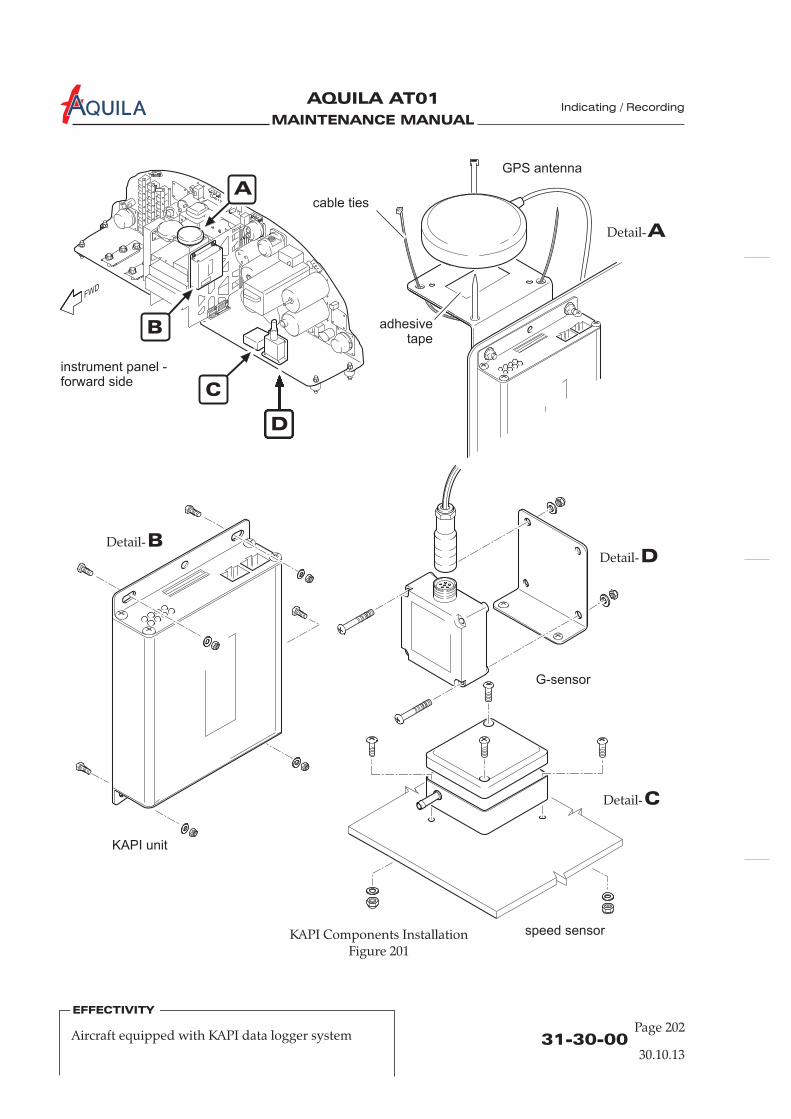
MAINTENANCE MANUAL
AQUILA AT01A Indicating / Recording
EFFECTIVITY
31-30-0030.10.13
EFFECTIVITY
Page 202Aircraft equipped with KAPI data logger system
KAPI Components InstallationFigure 201
B
C
D
instrument panel -forward side
KAPI unit
speed sensor
G-sensor
GPS antenna
cable ties
adhesivetape
A
BDetail-
ADetail-
DDetail-
CDetail-
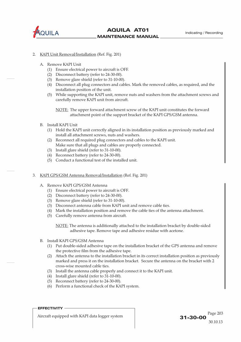
MAINTENANCE MANUAL
AQUILA AT01A Indicating / Recording
31-30-0030.10.13
EFFECTIVITY
Aircraft equipped with KAPI data logger systemPage 203
2. (Ref. Fig. 201)
A. Remove KAPI Unit(1) Ensure electrical power to aircraft is OFF.(2) Disconnect battery (refer to 24-30-00).(3) Remove glare shield (refer to 31-10-00).(4) Disconnect all plug connectors and cables. Mark the removed cables, as required, and the
installation position of the unit.(5) While supporting the KAPI unit, remove nuts and washers from the attachment screws and
carefully remove KAPI unit from aircraft.
The upper forward attachment screw of the KAPI unit constitutes the forwardattachment point of the support bracket of the KAPI GPS/GSM antenna.
B. Install KAPI Unit(1) Hold the KAPI unit correctly aligned in its installation position as previously marked and
install all attachment screws, nuts and washers.(2) Reconnect all required plug connectors and cables to the KAPI unit.
Make sure that all plugs and cables are properly connected.(3) Install glare shield (refer to 31-10-00).(4) Reconnect battery (refer to 24-30-00).(5) Conduct a functional test of the installed unit.
3. (Ref. Fig. 201)
A. Remove KAPI GPS/GSM Antenna(1) Ensure electrical power to aircraft is OFF.(2) Disconnect battery (refer to 24-30-00).(3) Remove glare shield (refer to 31-10-00).(3) Disconnect antenna cable from KAPI unit and remove cable ties.(4) Mark the installation position and remove the cable ties of the antenna attachment.(5) Carefully remove antenna from aircraft.
The antenna is additionally attached to the installation bracket by double-sidedadhesive tape. Remove tape and adhesive residue with acetone.
B. Install KAPI GPS/GSM Antenna(1) Put double-sided adhesive tape on the installation bracket of the GPS antenna and remove
the protective film from the adhesive tape.(2) Attach the antenna to the installation bracket in its correct installation position as previously
marked and press it on the installation bracket. Secure the antenna on the bracket with 2cross-wise mounted cable ties.
(3) Install the antenna cable properly and connect it to the KAPI unit.(4)
(6) Perform a functional check of the KAPI system.
KAPI Unit Removal/Installation
NOTE:
KAPI GPS/GSM Antenna Removal/Installation
NOTE:
Install glare shield (refer to 31-10-00).(5) Reconnect battery (refer to 24-30-00).

MAINTENANCE MANUAL
AQUILA AT01A Indicating / Recording
EFFECTIVITY
31-30-0030.10.13
EFFECTIVITY
Page 204Aircraft equipped with KAPI data logger system
4. (Ref. Fig. 201)
A. Remove KAPI Airspeed Sensor(1) Ensure electrical power to aircraft is OFF.(2) Disconnect battery (refer to 24-30-00).(3) Remove glare shield (refer to 31-10-00).(4) Disconnect pitot pressure line from the forward end of the sensor.
PLUG OR CAP THE SENSOR PORT AND THE END OF THE PRESSURELINE IMMEDIATELY AFTER DISCONNECTION TO PREVENT DIRT ORFOREIGN OBJECTS ENTERING THE SENSOR OR PRESSURE SYSTEM.
(5) Disconnect the plug connector from the sensor. Mark the removed plug as required.(6) Mark the installation position of the sensor and remove nuts and washers securing sensor.(7) Carefully remove sensor from aircraft.
B. Install KAPI Airspeed Sensor(1) Put sensor on instrument panel base plate and position it correctly as previously marked
(pitot pressure port of the sensor has to point towards flight direction). The correctinstallation position of the sensor is vital for a correct data acquisition.
(2) Secure KAPI airspeed sensor in its installation position using screws, washers and nuts.(3) Remove plugs/caps from sensor port and pitot pressure line. Reconnect pitot pressure line to
the respective sensor port. Make sure that the pressure line is properly connected to the portand secure the connection with a cable tie.
(4) Connect the required plug connector to the sensor. Make sure that all plugs and cables areproperly connected.
(5) Conduct a leak test of the pitot pressure system (refer to 34-11-00).(6) Install glare shield (refer to 31-10-00).(7) Reconnect battery (refer to 24-30-00).(8) Perform a functional check of the KAPI system.
5. (Ref. Fig. 201)
A. Remove KAPI G-Sensor(1) Ensure electrical power to aircraft is OFF.(2) Disconnect battery (refer to 24-30-00).(3) Remove glare shield (refer to 31-10-00).(4) Disconnect plug connector from sensor. Mark the removed plug as required.(5) Mark installation position of the sensor and remove nuts and washers from sensor mounting.
KAPI Airspeed Sensor Removal/Installation
CAUTION:
KAPI G-Sensor Removal/Installation
(6) Carefully remove sensor from its installation position.
B. Install KAPI G-Sensor(1) Place sensor on its mounting bracket and position it correctly as previously marked.
The correct installation position of the sensor is vital for a correct data acquisition.(2) Secure KAPI G-sensor on its installation bracket using attachment screws, washers and nuts.(3) Connect plug connector to sensor. Make sure that the plug is properly connected.(4) Install glare shield (refer to 31-10-00).(5) Reconnect battery (refer to 24-30-00).(6) Perform a functional check of the KAPI system.

MAINTENANCE MANUAL
AQUILA AT01A
CHAPTER 33
LIGHTS

MAINTENANCE MANUAL
AQUILA AT01A

MAINTENANCE MANUAL
AQUILA AT01A
Page 133 - TOC
Lights
30.10.13
TABLE OF CONTENTS
ChapterSection
Introduction 33-00-00 1General Description 33-00-00 1
Title Subject Page Effectivity
LIGHTS - GENERAL.........................................................................................33-00-00 1
INTERIOR LIGHTS - MAINTENANCE ........................................................33-10-00 201General 33-10-00 201Post Light Removal/Installation 33-10-00 201Nulite Removal/Installation 33-10-00 201Cockpit Light Removal/Installation 33-10-00 202
EXTERIOR LIGHTS - MAINTENANCE........................................................33-40-00 201General 33-40-00 201Landing Light Removal/Installation/Check 33-40-00 201Navigation/Position Light Bulb Replacement 33-40-00 202 Whelen lightsFlash Tube Assembly Replacement 33-40-00 202 Whelen lightsAnti-Collision Strobe Light Assembly Removal/Installation 33-40-00 202 Whelen lightsStrobe Light Module Removal/Installation 33-40-00 202 Whelen lightsNavigation/Position/Anti-Collision LightRemoval/Installation/Check 33-40-00 202 Aveo lights

MAINTENANCE MANUAL
AQUILA AT01A

MAINTENANCE MANUAL
AQUILA AT01A
33-00-00
Page 1
Lights
LIGHTS - GENERAL
1.
A. This chapter describes interior and exterior lighting systems used on the aircraft, includingremoval and installation procedures of components and light bulb replacement instructions.
2.
A. A cockpit light is installed for general cabin lighting, for emergency instrument panel lighting andas a reading light. The dimmable and swivel cockpit light is located in the roof of the cabin justbehind the seats. The light is controlled through a dimmer switch on the light.
The voltmeter, the ammeter, the oil temperature, the oil pressure and the cylinder headtemperature indicators as well as most of the avionic equipment are internally lighted. Refer toappropriate manufacturer's publications for maintenance instructions.In aircraft equipped for Night-VFR additional instrument and panel lighting is installed:If instruments do not have internal lighting they are illuminated by post lights or Nulites. As asecond source of light a LED row is integrated into the instrument panel cover. Both, LED rowand Nulites / post lights are controlled by a separate dimmer.To avoid shadowing on placards there is a placard bar below the switches on the bottom of theinstrument panel. For emergency lighting there are flashlights and all placards are luminescent.
B. Exterior lighting consists of wing tip navigation lights with integral anti-collision strobe lights andposition lights and a single landing light.
Introduction
General Description
30.10.13

MAINTENANCE MANUAL
AQUILA AT01A

MAINTENANCE MANUAL
AQUILA AT01A
INTERIOR LIGHTS - MAINTENANCE
1.
A.
aintenance of post lights and Nulites islimited to their removal and installation.
2.
A. Remove Post Light(1) Ensure electrical power to aircraft is OFF.(2) Disconnect battery (refer to 24-30-00).(3) Remove glare shield (refer to 31-10-00).(4) Disconnect electrical connector at back of post light.(5) Remove washer and nut securing post light to instrument panel and remove cable shoe and
post light.
B. Install Post Light(1) Put post light and cable shoe in position and secure using washer and nut.(2) Connect electrical connector at back of post light.(3) Install glare shield (refer to 31-10-00).(4) Reconnect battery (refer to 24-30-00).(5) Perform functional check.
General
Post Light Removal/Installation
If instruments do not have internal lighting, they are illuminated by post lights or Nulites. Postlights are LED lights that illuminate the instrument panel and function as instrument mountingbolts. Nulites are installed between the instrument and the instrument panel. They have a specialbezel that focuses the light toward the instrument. M
B. In Night-VFR equipped aircraft a LED row is integrated into the instrument panel cover. The rowis bonded to the instrument panel cover and therefore cannot be replaced or removed. Refer to31-10-00 for glare shield removal/installation procedures.
C. A cockpit light is installed in the roof of the cabin just behind the seats. Maintenance is limited tothe removal/installation of the light.
3.
A. Remove Nulite(1) Ensure electrical power to aircraft is OFF.(2) Disconnect battery (refer to 24-30-00).(3) Remove glare shield (refer to 31-10-00).(4) Cut electrical wires to Nulite .(5) Remove affected instrument as described in the appropriate chapter of this manual.(6) Remove Nulite.
Nulite Removal/Installation
Lights
33-10-00
Page 201
30.10.13
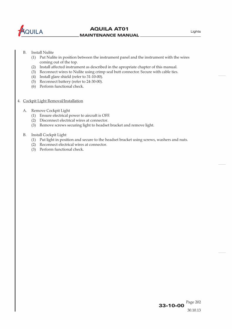
MAINTENANCE MANUAL
AQUILA AT01A Lights
33-10-00Page 202
30.10.13
B. Install Nulite(1) Put Nulite in position between the instrument panel and the instrument with the wires
coming out of the top.(2) Install affected instrument as described in the apropriate chapter of this manual.(3) Reconnect wires to Nulite using crimp seal butt connector. Secure with cable ties.(4) Install glare shield (refer to 31-10-00).(5) Reconnect battery (refer to 24-30-00).(6) Perform functional check.
4.
A. Remove Cockpit Light(1) Ensure electrical power to aircraft is OFF.(2) Disconnect electrical wires at connector.(3) Remove screws securing light to headset bracket and remove light.
B. Install Cockpit Light(1) Put light in position and secure to the headset bracket using screws, washers and nuts.(2) Reconnect electrical wires at connector.(3) Perform functional check.
Cockpit Light Removal/Installation

MAINTENANCE MANUAL
AQUILA AT01A
33-40-00
Page 201
Lights
30.10.13
EXTERIOR LIGHTS - MAINTENANCE
1.
A. The maintenance of exterior lights is limited to the removal and installation of components andlight bulb replacement.
B.
C. The illumination unit of the LED versions cannot be repaired. If one LED of the cluster has failedthe complete illumination unit has to be replaced.
2.
A. Remove Landing Light(1)(2) Remove upper cowling (refer to 71-10-00)(3) Disconnect landing light electrical wires at connector.(4) Remove screws securing landing light to cowling and remove landing light from aircraft.
B. Install Landing Light(1) Put landing light in position in the cowling and secure using screws.(2) Reconnect landing light electrical wires at connector.(3) Perform functional check, adjust landing light if necessary (refer to “Inspection/Check”
below).(4) Install upper cowling (refer to 71-10-00).
C. Landing Light Inspection/Check(1) Turn BAT switch ON.(2) Turn LDG light ON.(3) Verify the landing light works properly.(4) Turn OFF all switches.
General
Landing Light Removal/Installation/Check
The navigation / anti-collision lights installed are produced either by Whelen Engineering or AveoEngineering. Whelen lights are available either with or without LED navigation lights. Aveolights use LED's for navigation, position and anti-collision lights.
Ensure electrical power to aircraft is OFF.
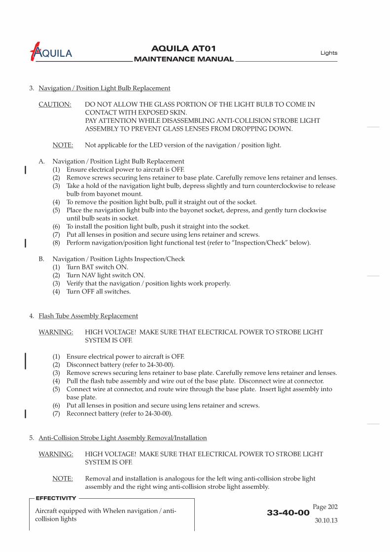
MAINTENANCE MANUAL
AQUILA AT01A
33-40-00Page 202
30.10.13
Lights
3.
DO NOT ALLOW THE GLASS PORTION OF THE LIGHT BULB TO COME INCONTACT WITH EXPOSED SKIN.PAY ATTENTION WHILE DISASSEMBLING ANTI-COLLISION STROBE LIGHTASSEMBLY TO PREVENT GLASS LENSES FROM DROPPING DOWN.
Not applicable for the LED version of the navigation / position light.
A. Navigation / Position Light Bulb Replacement(1) Ensure electrical power to aircraft is OFF.(2) Remove screws securing lens retainer to base plate. Carefully remove lens retainer and lenses.(3) Take a hold of the navigation light bulb, depress slightly and turn counterclockwise to release
bulb from bayonet mount.(4) To remove the position light bulb, pull it straight out of the socket.(5) Place the navigation light bulb into the bayonet socket, depress, and gently turn clockwise
until bulb seats in socket.(6) To install the position light bulb, push it straight into the socket.(7) Put all lenses in position and secure using lens retainer and screws.(8) Perform navigation/position light functional test (refer to “Inspection/Check” below).
B. Navigation / Position Lights Inspection/Check(1) Turn BAT switch ON.(2) Turn NAV light switch ON.(3) Verify that the navigation / position lights work properly.(4) Turn OFF all switches.
4.
HIGH VOLTAGE! MAKE SURE THAT ELECTRICAL POWER TO STROBE LIGHTSYSTEM IS OFF.
(1) Ensure electrical power to aircraft is OFF.(2) Disconnect battery (refer to 24-30-00).(3) Remove screws securing lens retainer to base plate. Carefully remove lens retainer and lenses.(4) Pull the flash tube assembly and wire out of the base plate. Disconnect wire at connector.(5) Connect wire at connector, and route wire through the base plate. Insert light assembly into
base plate.(6) Put all lenses in position and secure using lens retainer and screws.(7) Reconnect battery (refer to 24-30-00).
5.
HIGH VOLTAGE! MAKE SURE THAT ELECTRICAL POWER TO STROBE LIGHTSYSTEM IS OFF.
Removal and installation is analogous for the left wing anti-collision strobe lightassembly and the right wing anti-collision strobe light assembly.
Navigation / Position Light Bulb Replacement
CAUTION:
NOTE:
Flash Tube Assembly Replacement
WARNING:
Anti-Collision Strobe Light Assembly Removal/Installation
WARNING:
NOTE:
EFFECTIVITY
Aircraft equipped with Whelen navigation / anti-collision lights

MAINTENANCE MANUAL
AQUILA AT01A
33-40-00
Page 203
30.10.13
Lights
A. Remove Anti-Collision Strobe Light Assembly(1) Ensure electrical power to aircraft is OFF.(2) Disconnect battery (refer to 24-30-00).(3) Remove screws securing lens retainer to base plate. Carefully remove lens retainer and lenses.(4) Pull the flash tube assembly and wire out of the base plate. Disconnect wire at connector.(5) Remove screws securing base plate to wing tip fairing and remove base plate.(6) Disconnect wires from light at connector.
B. Install Anti-Collision Strobe Light Assembly(1) Reconnect wires to light at connector.(2) Position base plate on wing tip fairing and secure with screws.(3) Reconnect wire to flash light assembly at connector, and route wire through the base plate.
Insert light assembly into the base plate.(4) Put all lenses in position and secure using lens retainer and screws.(5) Reconnect battery (refer to 24-30-00).(6) Perform anti-collision light functional test (refer to “Inspection/Check” below).
C. Anti-Collision Strobe Light Inspection/Check(1) Turn BAT switch ON.(2) Turn ACL light switch ON.(3) Verify that anti-collision strobe light works properly.(4) Turn OFF all switches.
6.
HIGH VOLTAGE! MAKE SURE THAT ELECTRICAL POWER TO STROBE LIGHTSYSTEM IS OFF.
A. Remove Strobe Light Module(1) Ensure electrical power to aircraft is OFF.(2) Disconnect battery (refer to 24-30-00).(3) Remove baggage compartment floorboard / 211 JB (refer to 25-21-00).(4) Disconnect module connectors.(5) Remove bolts securing module to fuselage structure and remove module from aircraft.
B. Install Strobe Light Module(1) Position module on fuselage structure and secure using hardware.(2) Reconnect module connectors.(3) Reconnect battery (refer to 24-30-00).(4) Perform anti-collision light functional test (refer to “Inspection/Check” below).
C. Anti-Collision Strobe Light Inspection/Check(1) Turn BAT switch ON.(2) Turn ACL light switch ON.(3) Verify that anti-collision strobe lights work properly.(4) Turn OFF all switches.
Strobe Light Module Removal/Installation
WARNING:
EFFECTIVITY
Aircraft equipped with Whelen navigation / anti-collision lights

MAINTENANCE MANUAL
AQUILA AT01A Lights
3.
A. Remove Navigation/Position/Anti-Collision Light(1) Ensure electrical power to aircraft is OFF.(2) Remove screws securing base plate to wing tip fairing. Carefully remove light.(3) Disconnect wires from light at connector.
B. Install Navigation/Position/Anti-Collision Light(1) Reconnect wires to light at connector.(2) Position gasket and base plate on wing tip fairing and secure with screws.(3) Perform a navigation / position / anti-collision light functional test (refer to
“Inspection/Check” below).
C. Navigation/Position/Anti-Collision Light Inspection/Check(1) Turn BAT switch ON.(2) Turn NAV light switch ON.(3) Verify that the navigation / position light works properly.(4) Turn ACL light switch ON.(5) Verify that the anti-collision strobe light works properly.(6) Turn OFF all switches.
Navigation/Position/Anti-Collision Light Removal/Installation/Check
33-40-00Page 202
30.10.13
Aircraft equipped with Aveo navigation / anti-collision lights
EFFECTIVITY
MAINTENANCE MANUAL
AQUILA AT01A
CHAPTER 34
NAVIGATION

MAINTENANCE MANUAL
AQUILA AT01A

MAINTENANCE MANUAL
AQUILA AT01A
Page 134 - TOC
Navigation
30.10.13
TABLE OF CONTENTS
ChapterSection
NAVIGATION - GENERAL..................................................................34-00-00 1Introduction 34-00-00 1General Description 34-00-00 1
PITOT/STATIC SYSTEM – DESCRIPTION........................................34-11-00 1Introduction 34-11-00 1Description and Operation 34-11-00 1
PITOT/STATIC SYSTEM – MAINTENANCE ....................................34-11-00 201General 34-11-00 201Tools, Equipment and MaterialPitot-Static Tube Removal/Installation 34-11-00 201
Instruments Removal/Installation 34-11-00 202Inspection/Check 34-11-00 202
STALL WARNING SYSTEM – DESCRIPTION.................................34-18-00 1Introduction 34-18-00 1Description and Operation 34-18-00 1
STALL WARNING SYSTEM – MAINTENANCE .............................34-18-00 201General 34-18-00 201Transmitter Removal/Installation 34-18-00 201
Adjustment 34-18-00 201
ATTITUDE AND DIRECTION – MAINTENANCE .........................34-20-00 201General 34-20-00 201Magnetic Compass Removal/Installation 34-20-00 201Turn Coordinator Removal/Installation 34-20-00 201Attitude Indicator Removal/Installation 34-20-00 202Directional Gyro Removal/Installation 34-20-00 202Adjustment/Test 34-20-00 202
Title Subject Page Effectivity
34-11-00 201
P/S Heat Control Box Removal/Installation (optional) 34-11-00 202 P/S Heat
Warning Buzzer Removal/Installation 34-18-00 201
INTEGRATED FLIGHT SYSTEM – MAINTENANCE.....................34-25-00 201 Aspen EFD 1000General 34-25-00 201 Aspen EFD 1000EFD Removal/Installation 34-25-00 201 Aspen EFD 1000EFD Battery Replacement 34-25-00 202 Aspen EFD 1000Remote Sensor Module (RSM) Removal/Installation 34-25-00 202 Aspen EFD 1000Configuration Module (CM) Removal/Installation 34-25-00 203 Aspen EFD 1000Inspection/Check 34-25-00 204 Aspen EFD 1000
MAINTENANCE MANUAL
AQUILA AT01A Navigation
TABLE OF CONTENTS (Cont.)
ChapterSection
Title Subject Page Effectivity
Page 234 - TOC
30.10.13
INTEGRATED FLIGHT SYSTEM – MAINTENANCE.....................34-25-00 201 Garmin G500General 34-25-00 201 Garmin G500Garmin G500 Removal/Installation 34-25-00 201 Garmin G500Inspection/Check 34-25-00 204 Garmin G500
Garmin 430/530/650Garmin 430/530/650
INDEPENDENT POSITION DETERMINING -MAINTENANCE....................................................................................34-40-00 201 Bendix/King KMD 150
General 34-40-00 201 Bendix/King KMD 150KMD 150 Unit Removal/Installation 34-40-00 201 Bendix/King KMD 150GPS Antenna Removal/Installation 34-40-00 202 Bendix/King KMD 150Memory Battery 34-40-00 202 Bendix/King KMD 150Adjustment/Test 34-40-00 202 Bendix/King KMD 150
NDEPENDENT POSITION DETERMINING -MAINTENANCE....................................................................................34-40-00 201 FlymapL
COLLISION WARNING SYSTEM - MAINTENANCE....................34-45-00 201 FLARMGeneral 34-45-00 201 FLARMFLARM Unit Removal/Installation 34-45-00 201 FLARMGPS Antenna Removal/Installation 34-45-00 203 FLARMRadio Antenna Removal/Installation 34-45-00 203 FLARM.Display Unit Removal/Installation 34-45-00 204 FLARM
Bendix/KingBendix/KingBendix/King
INDEPENDENT POSITION DETERMINING -MAINTENANCE....................................................................................34-40-00 201 Garmin 430/530/650
General 34-40-00 201GPS Antenna Removal/Installation 34-40-00 201
I
General 34-40-00 201 FlymapLFlymapL Unit Removal/Installation 34-40-00 201 FlymapLGPS Antenna Removal/Installation 34-40-00 203 FlymapLAHRS Sensor Removal/Installation 34-40-00 203 FlymapLInspection/Check 34-40-00 205 FlymapL
DEPENDENT POSITIONING DETERMINING -MAINTENANCE....................................................................................34-50-00 201 Bendix/King
General 34-50-00 201Bendix/King KT 76A/C Transponder Removal/Installation 34-50-00 201Transponder Antenna Removal/Installation 34-50-00 202

MAINTENANCE MANUAL
AQUILA AT01A
Page 334 - TOC
30.10.13
TABLE OF CONTENTS (Cont.)
ChapterSection
Title Subject Page Effectivity
Navigation
DEPENDENT POSITIONING DETERMINING -MAINTENANCE....................................................................................34-50-00 201 Garmin Avionics
General 34-50-00 201 Garmin AvionicsGTX 327 / 328 / 330 Transponder Removal/Installation 34-50-00 202 Garmin AvionicsTransponder Antenna Removal/Installation 34-50-00 203 Garmin Avionics

MAINTENANCE MANUAL
AQUILA AT01A
MAINTENANCE MANUAL
AQUILA AT01A
34-00-00
Navigation
NAVIGATION - GENERAL
1.
A. This chapter describes units and components that provide aircraft navigational information.
2.
A. Different instruments and devices offer a means of determining flight conditions, aircraft attitudeand position of the aircraft over the ground.The following groups can be separated according to way data is sourced:
(1) Devices which use magnetic, gyroscopic and inertia forces to supply data to determineaircraft attitude and heading, including:(a) Attitude indicator(b) Directional gyro(c) Turn coordinator(d) Magnetic compass
(2) Devices which sense environmental conditions and use the data to influence navigation,including:(a) Airspeed indicator(b) Altimeter(c) Vertical speed indicator(d) Stall warning system
(3) Devices which provide information to determine position and are mainly independent ofground installations, including:(a) GPS receiver
(4) Devices which provide information to determine position and are mainly dependent onground installations. That includes:(a) VOR/LOC receiver(b) Transponder
Introduction
General Description
30.10.13
Page 1

MAINTENANCE MANUAL
AQUILA AT01A

MAINTENANCE MANUAL
AQUILA AT01A
34-11-00
PITOT/STATIC SYSTEM - DESCRIPTION
1.
A. The static and pitot pressure system supplies static and pitot pressure for the airspeed indicator,altimeter and vertical speed indicator as well as for the air data computer and the airspeed sensorof the KAPI logger (both are optional).
2.
A. Pitot-Static Tube and LinesPitot and static pressures are picked up by the pitot-static tube installed on the underside of theleft wing, and carried through lines inside the wing and fuselage to the gauges on the instrumentpanel. The pitot and static pressure lines have filter elements to prevent foreign material such asdust or water entering the flight instruments. These filter elements are located in the lines andmay be easiliy replaced.
Introduction
Description and Operation
B. Pitot HeatingOptional the aircraft is equipped with a heated pitot tube to prevent icing. It consists of a heatingcoil and a temperature sensor inside the pitot tube and a control box installed on the bottom of theinstrument panel (left-hand side). Both are connected by electrical wires. Additionally there is awarning light in the instrument panel that indicates if the pitot heat is switched off or if theheating is not working even though it is switched on and the temperature in the pitot tube isbelow approx. 50°C (122°F).
C. Figure 1 shows the pitot/static system schematically.
Navigation
30.10.13
Page 1

MAINTENANCE MANUAL
AQUILA AT01A
34-11-00Page 2
Navigation
30.10.13
Pitot-Static System SchematicFigure 1 static pressure
pitot pressure
pitot-static tube
filter
airspeed indicator
airspeed sensorKAPI data logger
(optional)
air data computer(optional)
altimeter
vertical speed Indicator
compensation tank

MAINTENANCE MANUAL
AQUILA AT01A
34-11-00
Page 201
Navigation
PITOT/STATIC SYSTEM - MAINTENANCE
1.
A. Proper maintenance of the pitot/static system is essential for proper altimeter, airspeed and verticalspeed indications. Moisture, obstructions and leaks in the system will result in erroneous, erraticor zero readings on the associated instruments.Filters should be regularly inspected and replaced as required.
B. A cover should be placed over the pitot-static tube when the aircraft is parked, to prevent insectsand water from entering the pitot orifice.
2.
Quantity Equipment Parts No. Manufacturer
6.B./6.C. 1 Sphygmo- - commerciallymanometer pres- availablesure bulb withcheck valve
6.B. 1 Surgical hose commerciallyavailable
3.
A. Remove Pitot-Static Tube(1) Ensure electrical power to aircraft is OFF.(2) Remove screws securing pitot-static tube to wing skin.(3) Identify and disconnect pitot / static lines and electrical connector (optional) at pitot tube.(4) Remove pitot-static tube from aircraft.
B. Install Pitot-Static Tube(1) Connect pitot / static lines and electrical connector (optional) at pitot-static tube(2) Put pitot-static tube in position on the wing and secure using screws.(3) Perform a pitot-static system functional test (refer to “Inspection/Check” below).
General
Tools, Equipment and Material
Pitot-Static Tube Removal/Installation
CAUTION:
CAUTION:
NEVER BLOW COMPRESSED AIR THROUGH PITOT OR STATIC LINES TOWARDINSTRUMENTS AS THIS CAN CAUSE DAMAGE TO INSTRUMENTS.
ENSURE THE PITOT HEAT (OPTIONAL) IS SWITCHED OFF AND THE TUBE HASCOOLED DOWN BEFORE TOUCHING THE TUBE. A HEATED PITOT TUBE CANGET EXTREMELY HOT DURING OPERATION.
30.10.13
MAINTENANCE MANUAL
AQUILA AT01A
34-11-00Page 202
Navigation
4. (optional)
NEVER OPERATE PITOT HEATING WITHOUT THE CONTROL BOX AS THIS CANDESTROY THE PITOT TUBE.
A. Remove the Control Box(1) Ensure electrical power to aircraft is OFF.(2) Disconnect battery (refer to 24-30-00).(3) Remove glare shield (refer to 31-10-00).(4) Disconnect electrical connector from control box.(5) Remove cable ties securing control box to instrument panel.(6) Remove control box from aircraft.
B. Install the Control Box(1) Put control box in position in instrument panel and secure using cable ties.(2) Reconnect electrical connector to control box.(3) Install glare shield (refer to 31-10-00).(4) Reconnect battery (refer to 24-30-00).(5) Carry out a functional test of the P/S heating.
erform a pitot-static system functional test (refer to “Inspection/Check” below).
P/S Heat Control Box Removal/Installation
CAUTION:
5.
A. Remove an Instrument
PLUG OR CAP INSTRUMENT PORTS IMMEDIATELY AFTER DISCONNECTINGPITOT OR STATIC LINES TO PREVENT DIRT OR FOREIGN MATERIAL FROMENTERING.
(1) Gain access to the back of instrument and disconnect static/pitot hose from instrument.(2) While supporting the instrument, remove screws securing instrument to instrument panel.(3) Remove instrument.
B. Install an Instrument(1) Place instrument to instrument panel and secure with screws.(2) Reconnect static/pitot hose to instrument.(3) P
6.
A. After any component replacement or repair, the system should be checked for proper function anda leakage test should be performed.
B. Pitot System Leak Test(1) Fasten surgical hose and sphygmomanometer bulb over pitot head.(2) Pump bulb until airspeed indicator registers 150 KIAS.(3) Close check valve.(4) Wait 15 seconds for airspeed indicator to stabilize.
Instruments Removal/Installation
CAUTION:
Inspection/Check
30.10.13

MAINTENANCE MANUAL
AQUILA AT01A
34-11-00
Page 203
Navigation
30.10.13
P/S Heat Control BoxFigure 202
A
ADetail-
cable ties
electricalconnector
NOTE: Example View!Equipment installed on instrument panel mayvary depending on aircraft configuration.

MAINTENANCE MANUAL
AQUILA AT01A
34-11-00Page 204
Navigation
30.10.13
(5) Observe airspeed indicator for one minute.(6) The airspeed should drop no more than 10 KIAS.(7) Slowly release check valve so pressure is reduced gradually to prevent instrument damage.(8) If test reveals a leak in system, check all connections for tightness and repair faulty
components.
C. Static System Leak Test(1) Tape over static ports at pitot-static tube.(2) Insert a “T” in a static pressure line.(3) Squeeze sphygmomanometer bulb and close check valve to establish a vacuum inside bulb.(4) Connect sphygmomanometer to the static pressure line.(5) Slowly open air bulb check valve until altimeter indicates a 1000 ft increase in altitude then
close check valve to trap suction in system.(6) While increasing suction and altimeter indicating 1000 ft, ensure that the airspeed indicator
shows an increase and the vertical speed indicator shows a climb indication.(7) Leakage must not exceed 100 ft/min of altitude loss as indicated on the altimeter.(8) If leakage rate exceeds the maximum allowable, check all fittings and hoses for condition and
tightness and repeat leak test.(9) If leakage rate still exceeds the maximum allowable, undertake the following:(10) Disconnect static pressure lines from airspeed indicator, vertical speed indicator and altitude
encoder.(11) Connect lines together using suitable fittings so altimeter is the only instrument still
connected to static pressure system.(12) Repeat leak test to ascertain whether the static pressure system or the bypassed instruments
are causing the leakage. If instruments are at fault, they must be repaired by an approvedrepair station or replaced. If static pressure system is faulty, proceed as follows:
DO NOT APPLY POSITIVE PRESSURE WITH AIRSPEED INDICATOR ORVERTICAL SPEED INDICATOR CONNECTED TO STATIC PRESSURE SYSTEM.
(13) Remove sphygmomanometer assembly.(14) Insert a “T” in a static pressure line.(15) Attach hose to “T” and slowly apply positive pressure until altimeter indicates a 500 ft
decrease in altitude. Maintain this altimeter indication while checking for leaks.(16) Coat line with a solution of mild soap and water, watching for bubbles to locate leaks.(17) Tighten leaking connections. Repair or replace defective components.(18) Reconnect airspeed, vertical speed indicator and altitude encoder. Repeat static system leak
test.
CAUTION:

MAINTENANCE MANUAL
AQUILA AT01A
34-18-00
STALL WARNING SYSTEM - DESCRIPTION
1.
A. The aircraft is equipped in with a stall warning system. It signals an approaching stall to the pilotby an audible alarm in the cockpit.
2.
A. The stall warning system consists of a mechanical transmitter, located in the leading edge of theleft wing and a warning buzzer behind the instrument panel. Both are connected by electricalwires.
B. As the aircraft approaches a stall, the low pressure on the upper surface of the wings movesforward around the leading edge of the wings. As a result, a microplate at the transmitter isdeflected upwards. A mechanical contact is made which sends an electrical signal to the warningbuzzer in the cockpit. The warning buzzer gives off a 2 kHz alerting tone.
Introduction
Description and Operation
Navigation
30.10.13
Page 1

MAINTENANCE MANUAL
AQUILA AT01A
MAINTENANCE MANUAL
AQUILA AT01A
34-18-00
Page 201
STALL WARNING SYSTEM - MAINTENANCE
1.
A. Maintenance is limited to the removal/installation of system components. In wintry conditions,make sure that the system transmitter microplate is always clear of ice and snow.
2.
A. Remove Transmitter(1) Ensure electrical power to aircraft is OFF.(2) Remove 3 screws securing transmitter covering to wing structure. Carefully pull transmitter
with covering out of wing.(3) Disconnect electrical connector.(4) Remove 2 screws securing covering to transmitter and remove covering.
B. Install Transmitter(1) Install transmitter covering on transmitter.(2) Connect electrical connector.(3) Put transmitter with covering in position and secure to wing structure.
4.
The stall warning system is so adjusted that the system will come into action approx. 10 – 15 km/h(6 - 8kts) before the aircraft stalls. If these values are not achieved, it is possible to modify thesystem behavior by shortening the microplate by a few millimeters. This will lower the speed thesystem is activated. A test for proper system operation is only possible in flight. Repeat theprocedure until the microplate has the correct length.
General
Transmitter Removal/Installation
Adjustment
(4) Perform a flight test to check the stall warning system (refer to “Adjustment” below).
3.
A. Remove Warning Buzzer(1) Ensure electrical power to aircraft is OFF.(2) Disconnect battery (refer to 24-30-00).(3) Remove glare shield (refer to 31-10-00).(4) Disconnect electrical connector.(5) Remove nuts securing buzzer to instrument panel and remove buzzer.
B. Install Warning Buzzer(1) Put buzzer in position at back of instrument panel and secure using two nuts.(2) Connect electrical connector.(3) Install glare shield (refer to 31-10-00).(4) Reconnect battery (refer to 24-30-00).(5) Perform a functional check of the stall warning system.
A.
Warning Buzzer Removal/Installation
Navigation
30.10.13

MAINTENANCE MANUAL
AQUILA AT01A Navigation

MAINTENANCE MANUAL
AQUILA AT01A
34-20-00
Page 201
ATTITUDE AND DIRECTION - MAINTENANCE
1.
A. The construction and function of the magnetic compass, turn coordinator, attitude indicator anddirectional gyro is conventional, with no special features.
B. Maintenance is limited to component removal and re-installation.
2.
A. Remove Magnetic Compass(1) Ensure electrical power to aircraft is OFF.(2)(3)(4) Disconnect electrical wires from compass.(5) Remove screws securing compass and remove compass from aircraft.
B. Install Magnetic Compass(1) Put compass in position and secure using screws.(2) Connect electrical wires to magnetic compass.(3) Install glare shield (refer to 31-10-00).(4) Re (refer to 24-30-00).(5) Do a compass swing (refer to “Adjustment/Test” below).
3.
A. Remove Turn Coordinator(1)(2)
(4) Disconnect electrical connector from turn coordinator.(5) While supporting the turn coordinator, remove screws securing turn coordinator to
instrument panel.(6) Remove turn coordinator from aircraft.
B. Install Turn Coordinator(1) Put turn coordinator in position in instrument panel and secure using screws.(2) Reconnect electrical connector to turn coordinator.(3)
General
Magnetic Compass Removal/Installation
Turn Coordinator Removal/Installation
CAUTION: GYROS ARE DELICATE AND CAN NOT WITHSTAND THE SHOCK OF BEINGDROPPED, JARRED OR STRUCK BY PIECES OF EQUIPMENT. DO NOT PLACEGYROS ON ANY HARD SURFACE. PAD WITH GENEROUS FOAM.
Disconnect battery (refer to 24-30-00).Remove glare shield (refer to 31-10-00).
connect battery
Ensure electrical power to aircraft is OFF.Disconnect battery (refer to 24-30-00).
(3) Remove glare shield (refer to 31-10-00).
Install glare shield (refer to 31-10-00).(4) Reconnect battery (refer to 24-30-00).(5) Conduct a functional test of the unit.
Navigation
30.10.13
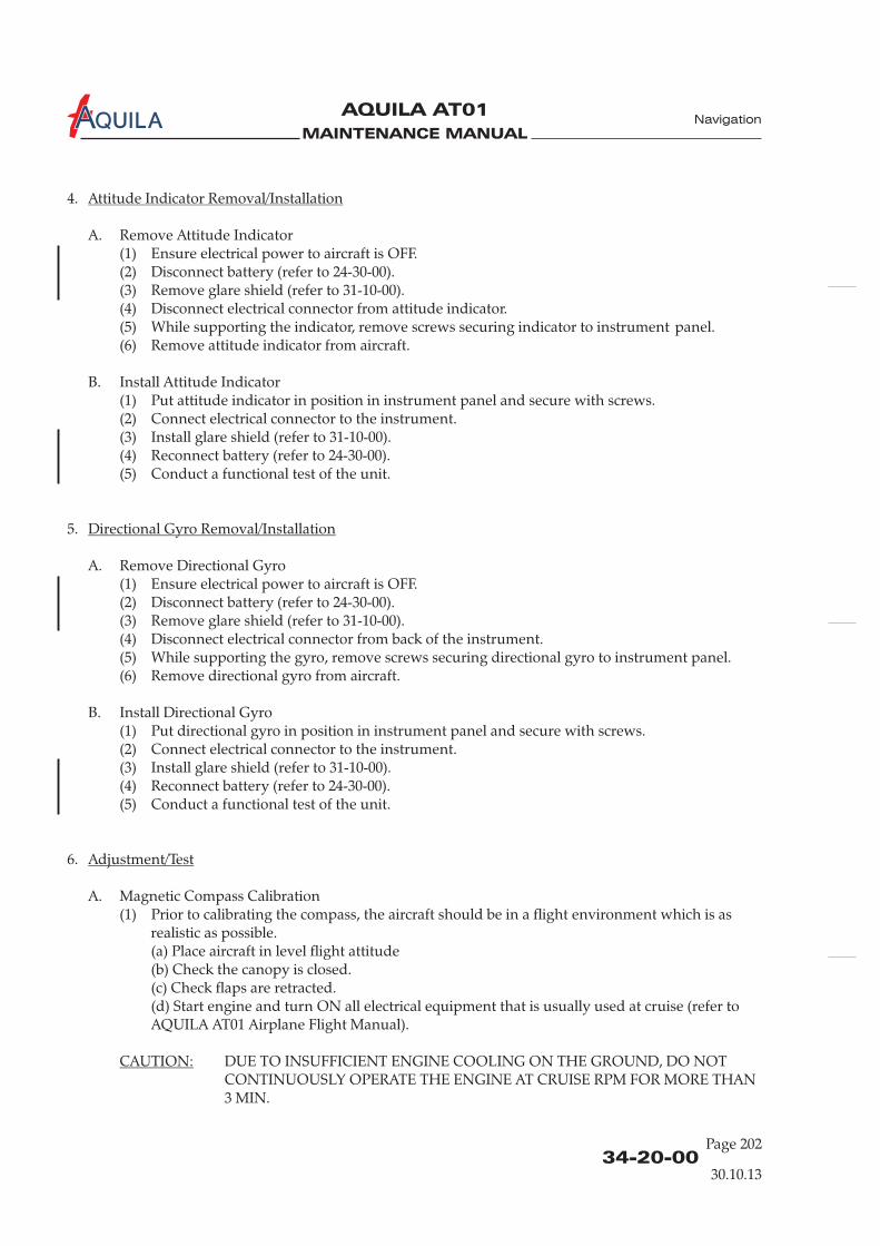
MAINTENANCE MANUAL
AQUILA AT01A
34-20-00Page 202
4.
A. Remove Attitude Indicator(1)
(3)(4) Disconnect electrical connector from attitude indicator.(5) While supporting the indicator, remove screws securing indicator to instrument panel.(6) Remove attitude indicator from aircraft.
B. Install Attitude Indicator(1) Put attitude indicator in position in instrument panel and secure with screws.(2) Connect electrical connector to the instrument.(3) Install glare shield (refer to 31-10-00).(4) Reconnect battery (refer to 24-30-00).(5) Conduct a functional test of the unit.
A. Remove Directional Gyro(1)
(4) Disconnect electrical connector from back of the instrument.(5) While supporting the gyro, remove screws securing directional gyro to instrument panel.(6) Remove directional gyro from aircraft.
B. Install Directional Gyro(1) Put directional gyro in position in instrument panel and secure with screws.(2) Connect electrical connector to the instrument.(3) Install glare shield (refer to 31-10-00).(4) Reconnect battery (refer to 24-30-00).(5) Conduct a functional test of the unit.
6.
A. Magnetic Compass Calibration(1) Prior to calibrating the compass, the aircraft should be in a flight environment which is as
realistic as possible.(a) Place aircraft in level flight attitude(b) Check the canopy is closed.(c) Check flaps are retracted.(d) Start engine and turn ON all electrical equipment that is usually used at cruise (refer toAQUILA AT01 Airplane Flight Manual).
DUE TO INSUFFICIENT ENGINE COOLING ON THE GROUND, DO NOTCONTINUOUSLY OPERATE THE ENGINE AT CRUISE RPM FOR MORE THAN3 MIN.
Attitude Indicator Removal/Installation
irectional Gyro Removal/Installation
Adjustment/Test
CAUTION:
Ensure electrical power to aircraft is OFF.(2) Disconnect battery (refer to 24-30-00).
Remove glare shield (refer to 31-10-00).
5.
Ensure electrical power to aircraft is OFF.(2) Disconnect battery (refer to 24-30-00).(3) Remove glare shield (refer to 31-10-00).
D
Navigation
30.10.13

MAINTENANCE MANUAL
AQUILA AT01A
34-20-00
Page 203
30.10.13
Navigation
(e) Run engine and set throttle at cruise position.
When performing maintenance on the magnetic compass, use a non-magnetic orplastic screwdriver.
(2) Remove screws securing access plate to compass casing to reveal adjustment screws.(3) Set adjustment screws of compensator to zero. Zero position is indicated when dot of screw
is aligned with dot on compass frame.(4) Taxi airplane to compass rose.(5) Align centerline of aircraft on magnetic North heading. Adjust N - S set screw until compass
reads North.(6) Align centerline of aircraft on magnetic East heading. Adjust E - W set screw until compass
reads East.(7) Align centerline of aircraft on magnetic South heading and note resulting South error.(8) Adjust N - S set screw until half of error is removed.(9) Align centerline of aircraft on magnetic West heading and note resulting West error.(10) Adjust E - W set screw until half of error is removed.(11) Align centerline of aircraft in successive magnetic 30-degree headings and record compass
readings on appropriate compass correction (deviation) card. Deviations must not exceed 10degrees on any heading.
NOTE:

MAINTENANCE MANUAL
AQUILA AT01A

MAINTENANCE MANUAL
AQUILA AT01A
INTEGRATED FLIGHT SYSTEM - MAINTENANCE
All Service Information released from AQUILA and related to software versions have to beattached to this maintenance manual for continuing airworthiness!
1.
A. This section provides instructions necessary for authorized personnel to inspect and maintain theEFD1000 system. I
B. The Aspen EFD1000 PFD system is comprised of the primary flight display (PFD), remote sensormodule (RSM) and configuration module (CM). The EFD1000 PFD system provides display ofattitude, airspeed, altitude, direction of flight, vertical speed, turn rate and turn quality. Thesystem may optionally provide display of navigation information through interfaces to GPSreceivers and/or VHF navigation receivers.
C. The operation of the Aspen EFD 1000 PFD requires the following software version:
- for ASPEN EFD 1000 PFD: software version MAP 2.x or newer approved versions
Software-updates will be released via Service Information (SI) at www.aquila-aviation.de.
A.
General
nstructions for removal and replacement of LRUs that have been previouslyinstalled in the aircraft are included.
Only install ETSO’d software versions (for airplanes registered in Europe or countries where theEASA-TC has been accepted) respectively FAA approved software versions (for airplanesregistered in the USA or countries where the FAA-TC has been accepted).
The actual software version is documented in the aircraft equipment list, located in chapter 6.5.1 ofthe AQUILA AT01 Airplane Flight Manual.
D. No special tools are required for the removal and replacement of any system LRUs. If a LRU isfound to be defective it should be removed and returned to a properly rated facility for repair orreplacement. If fasteners are deformed in any way, they must be replaced.
E. For bonding checks on the AQUILA AT01 no procedures or equipment are necessary other thanthat which are commonly expected for bonding measurements on small aircraft. Refer toAC 43.13-1B, chapter 11, section 15 “Grounding and Bonding” for further information on bondingcheck procedures and equipment.
F. Refer to the Aspen EFD1000 and EFD500 SW v2.x Installation Manual, P/N 900-00003-001, revisionZ or later and the Aspen EFD1000 and EFD500 Instructions for Continued Airworthiness, P/N 900-00012-001, revision K or later for additional maintenance information on the EFD 1000 system andfastener identification and discard recommendations.
2.
Remove EFD(1) Verify electrical power to aircraft is OFF.(2) (refer to 24-30-00).
EFD Removal/Installation
Disconnect battery
34-25-00
Page 201
Navigation
EFFECTIVITY
Aircraft equipped with ASPEN EFD1000 PFD
30.10.13
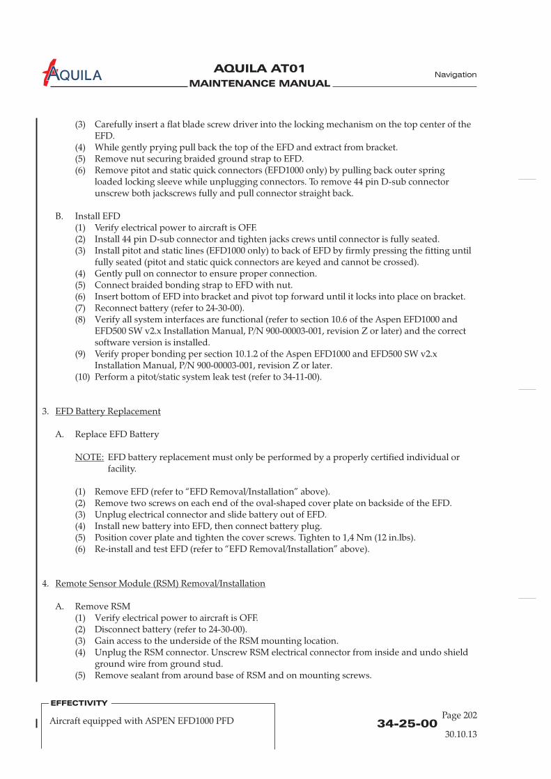
MAINTENANCE MANUAL
AQUILA AT01A
(3) Carefully insert a flat blade screw driver into the locking mechanism on the top center of theEFD.
(4) While gently prying pull back the top of the EFD and extract from bracket.(5) Remove nut securing braided ground strap to EFD.
B. Install EFD(1) Verify electrical power to aircraft is OFF.(2)
erify all system interfaces are functional (refer to Aspen EFD1000 andEFD500 SW v2.x Installation Manual, P/N 900-00003-001, revision Z or later
of the Aspen EFD1000 and EFD500 SW v2.xInstallation Manual, P/N 900-00003-001, revision Z or later
3.
(refer to “EFD Removal/Installation” above)
4.
erify electrical power to aircraft is OFF.(2) (refer to 24-30-00).(3)
(6) Remove pitot and static quick connectors (EFD1000 only) by pulling back outer springloaded locking sleeve while unplugging connectors. To remove 44 pin D-sub connectorunscrew both jackscrews fully and pull connector straight back.
Install 44 pin D-sub connector and tighten jacks crews until connector is fully seated.(3) Install pitot and static lines (EFD1000 only) to back of EFD by firmly pressing the fitting until
fully seated (pitot and static quick connectors are keyed and cannot be crossed).(4) Gently pull on connector to ensure proper connection.(5) Connect braided bonding strap to EFD with nut.(6) Insert bottom of EFD into bracket and pivot top forward until it locks into place on bracket.(7) Reconnect battery (refer to 24-30-00).(8) V section 10.6 of the
) and the correctsoftware version is installed.
(9) Verify proper bonding per section 10.1.2.
(10) Perform a pitot/static system leak test (refer to 34-11-00).
A. Replace EFD Battery
EFD battery replacement must only be performed by a properly certified individual orfacility.
(1) Remove EFD (refer to “EFD Removal/Installation” above).(2) Remove two screws on each end of the oval-shaped cover plate on backside of the EFD.(3) Unplug electrical connector and slide battery out of EFD.(4) Install new battery into EFD, then connect battery plug.(5) Position cover plate and tighten the cover screws. Tighten to 1,4 Nm (12 in.lbs).(6) Re-install and test EFD .
A. Remove RSM(1) V
Gain access to the underside of the RSM mounting location.(4) Unplug the RSM connector. Unscrew RSM electrical connector from inside and undo shield
ground wire from ground stud.(5) Remove sealant from around base of RSM and on mounting screws.
EFD Battery Replacement
Remote Sensor Module (RSM) Removal/Installation
NOTE:
Disconnect battery
34-25-00Page 202
Navigation
30.10.13
EFFECTIVITY
Aircraft equipped with ASPEN EFD1000 PFD

MAINTENANCE MANUAL
AQUILA AT01A
(6) Remove four 8-32 non-ferrous mounting screws from RSM and remove RSM from aircrafttaking care to guide 24 inch “pigtail” connector out through ½ inch hole in aircraft skin.
Replace the O-ring on the RSM. Contact Aspen Avionics for O-ring replacement(256-00001-001).
(3) Verify RSM shim is installed between aircraft skin and RSM if required.(4) Feed circular connector down through ½ inch hole in aircraft skin and mount RSM (vent
hole faces aft) with four 8-32 non-ferrous screws.
It is critical that the screws are non-ferrous to avoid compass errors.
Connect the circular electrical connector and cable tie harness to prevent chafing andinterference.
(6) Connect shield ground wire to ground stud.(7) Seal around base and on top of four mounting screws of the RSM using
(8) Reconnect battery (refer to 24-30-00).(9) Verify proper bonding per section 10.1.2 and perform RSM calibration per section 10.5 of the
(10) Check OAT operation per section 10.6.4 and check RSM GPS operation per section 10.6.6 ofthe
.
A. Remove CM(1)
Cut the two cable ties affixing the CM to the PFD wiring harness.(4) Unplug the Molex connector by pressing down on the locking tab and gently pulling the
connector from the module.
Plug the Molex connector into the module until it clicks.(3) Cable tie the module to the PFD wiring harness..(4) Reconnect battery (refer to 24-30-00).(5) Perform the installation menu unit configuration per section 10.4.5 of the
.(6) Perform RSM calibration per section 10.5 of the
B. Install RSM(1) Verify electrical power to aircraft is OFF.(2)
Tighten to 1,4-1,7 Nm (12-15 in.lbs).
(5)
a good qualityelectrical sealant (Sikaflex-221 or equivalent, silicone-free).
Aspen EFD1000 and EFD500 SW v2.x Installation Manual, P/N 900-00003-001, revision Z orlater.
Aspen EFD1000 and EFD500 SW v2.x Installation Manual, P/N 900-00003-001, revision Zor later
5.
Verify electrical power to aircraft is OFF.(2) (refer to 24-30-00).(3)
B. Install CM(1) Verify electrical power to aircraft is OFF.(2)
Aspen EFD1000 andEFD500 SW v2.x Installation Manual, P/N 900-00003-001, revision Z or later
Aspen EFD1000 and EFD500 SW v2.xInstallation Manual, P/N 900-00003-001, revision Z or later.
NOTE:
Configuration Module (CM) Removal/Installation
Disconnect battery
34-25-00
Page 203
Navigation
30.10.13
EFFECTIVITY
Aircraft equipped with ASPEN EFD1000 PFD

MAINTENANCE MANUAL
AQUILA AT01A
6.
mΩ
Inspection/Check
A. All units, brackets, installation hardware and wiring of the EFD1000 system should be checked asdefined below during annual inspection. Items found to be defective should be repaired orreplaced prior to returning the aircraft to service. The performance of this inspection should notcreate the need for additional protective treatment (Alodine, paint, etc) of surfaces within theaircraft.
B. EFD Inspection(1) Inspect the EFD(s) for damage and verify proper operation using the documents identified in
section 1 of the Aspen EFD1000 and EFD500 Instructions for Continued Airworthiness,P/N 900-00012-001, revision K or later.
(2) Check the EFD wiring, pneumatic tubing and quick disconnects for integrity, damage,chafing or excessive wear.
(3) Check EFD braided bonding strap for proper termination at the EFD and aircraft groundingpoint to maintain HIRF and lightning compliance.
(4) Verify the resistance is 3 m from EFD ground stud to airframe ground.(5) Inspect the installation of the EFD for corrosion on the EFD and the mounting structure.(6) Inspect the fasteners for tightness and general condition.
C. RSM Inspection(1) Inspect the RSM(s) visually for damage and wear on the lightning strip.(2) Check RSM wiring for damage, chafing or excessive wear.(3) Verify the RSM doubler plate bonding resistance from the ground stud to airframe ground is
3 to maintain HIRF and lightning compliance.(4) Inspect the RSM installation incl. doubler for corrosion on the RSM, the RSM shim (optional),
the fuselage skin and the doubler.(5) Inspect the installation for cracks in the fuselage and loose or damaged fasteners.
D. Configuration Module(1) Check the configuration module(s) for damage.(2) Check the configuration module wiring for damage, chafing or excessive wear.
≤
≤
Ω
34-25-00Page 204
Navigation
30.10.13
EFFECTIVITY
Aircraft equipped with ASPEN EFD1000 PFD
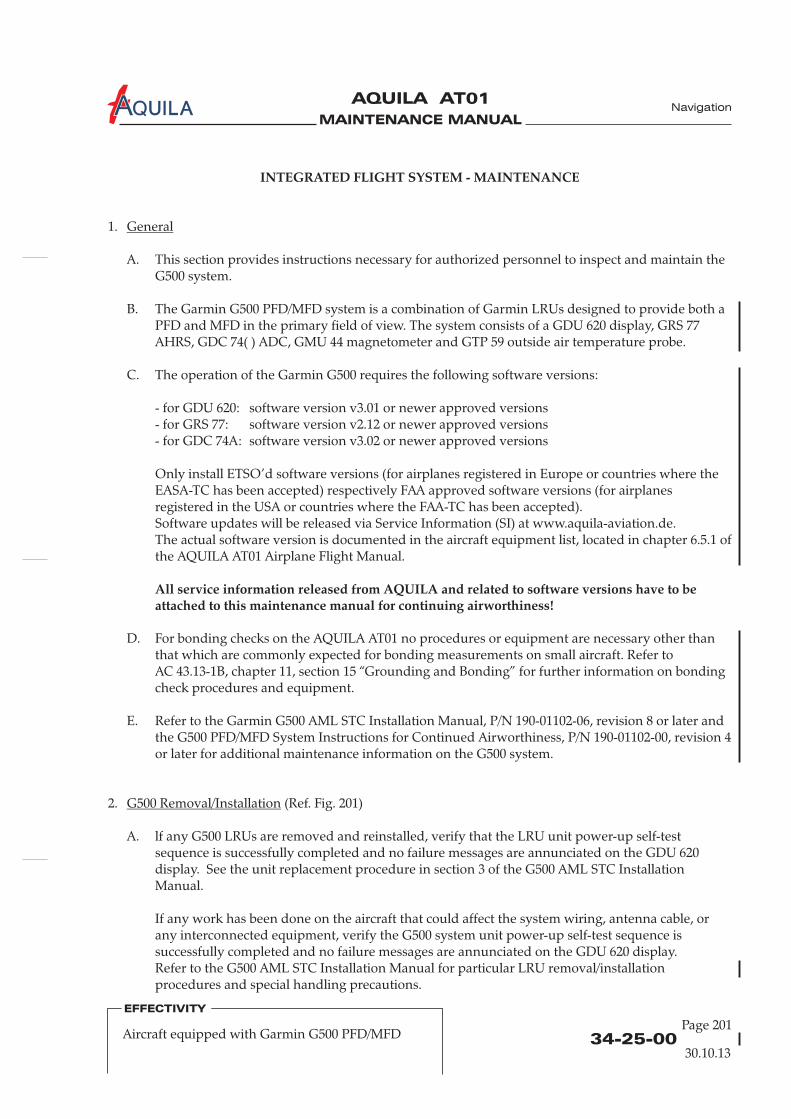
MAINTENANCE MANUAL
AQUILA AT01A
INTEGRATED FLIGHT SYSTEM - MAINTENANCE
All service information released from AQUILA and related to software versions have to beattached to this maintenance manual for continuing airworthiness!
1.
A. This section provides instructions necessary for authorized personnel to inspect and maintain theG500 system.
B. The Garmin G500 PFD/MFD system is a combination of Garmin LRUs designed to provide both aPFD and MFD in the primary field of view. The system consists of a GDU 620 display, GRS 77AHRS, GDC 74( ) ADC, GMU 44 magnetometer and GTP 59 outside air temperature probe.
C. The operation of the Garmin G500 requires the following software versions:
- for GDU 620: software version v3.01 or newer approved versions- for GRS 77: software version v2.12- for GDC 74A: software version v3.02
Only install ETSO’d software versions (for airplanes registered in Europe or countries where theEASA-TC has been accepted) respectively FAA approved software versions (for airplanesregistered in the USA or countries where the FAA-TC has been accepted).Software updates will be released via Service Information (SI) at www.aquila-aviation.de.The actual software version is documented in the aircraft equipment list, located in chapter 6.5.1 ofthe AQUILA AT01 Airplane Flight Manual.
2. (Ref. Fig. 201)
A. lf any G500 LRUs are removed and reinstalled, verify that the LRU unit power-up self-testsequence is successfully completed and no failure messages are annunciated on the GDU 620display. See the unit replacement procedure in section 3 of the G500 AML STC InstallationManual.
If any work has been done on the aircraft that could affect the system wiring, antenna cable, orany interconnected equipment, verify the G500 system unit power-up self-test sequence issuccessfully completed and no failure messages are annunciated on the GDU 620 display.Refer to the G500 AML STC Installation Manual for particular LRU removal/installationprocedures and special handling precautions.
General
G500 Removal/Installation
or newer approved versionsor newer approved versions
D. For bonding checks on the AQUILA AT01 no procedures or equipment are necessary other thanthat which are commonly expected for bonding measurements on small aircraft. Refer toAC 43.13-1B, chapter 11, section 15 “Grounding and Bonding” for further information on bondingcheck procedures and equipment.
E. Refer to the Garmin G500 AML STC Installation Manual, P/N 190-01102-06, revision 8 or later andthe G500 PFD/MFD System Instructions for Continued Airworthiness, P/N 190-01102-00, revision 4or later for additional maintenance information on the G500 system.
34-25-00
Page 201
Navigation
30.10.13
EFFECTIVITY
Aircraft equipped with Garmin G500 PFD/MFD
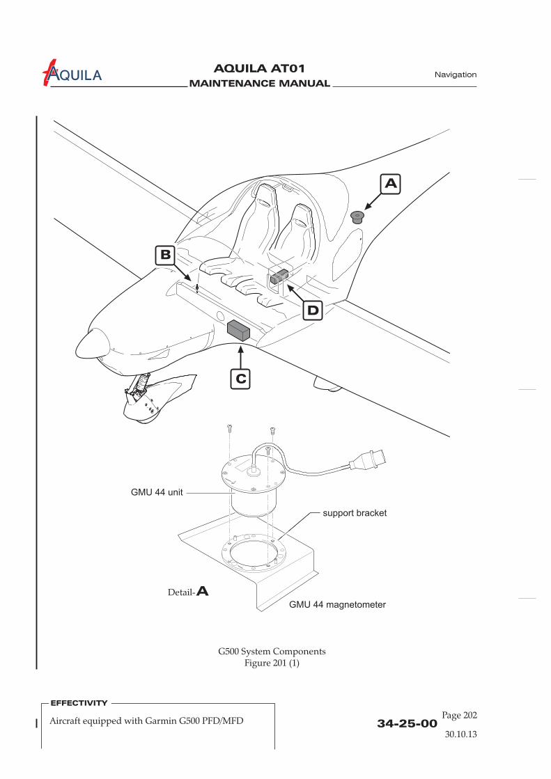
MAINTENANCE MANUAL
AQUILA AT01A
34-25-00Page 202
Navigation
30.10.13
EFFECTIVITY
Aircraft equipped with Garmin G500 PFD/MFD
A
B
C
D
G500 System ComponentsFigure 201 (1)
ADetail-
GMU 44 magnetometer
support bracket
GMU 44 unit

MAINTENANCE MANUAL
AQUILA AT01A
34-25-00
Page 203
Navigation
30.10.13
EFFECTIVITY
Aircraft equipped with Garmin G500 PFD/MFD
G500 System ComponentsFigure 201 (2)
BDetail-
CDetail-
DDetail-
supportbracket
supportbracket
GRS 77 (AHRS sensor)
AHRS unit
GDC 74A (air data computer)
GDC 74A unit
GTP 59 (OAT sensor)
attachmentclamp

MAINTENANCE MANUAL
AQUILA AT01A
34-25-00Page 204
Navigation
30.10.13
EFFECTIVITY
Aircraft equipped with Garmin G500 PFD/MFD
3.
A. All G500 system LRUs are designed to detect internal failures. A thorough self-test is executedautomatically upon application of power to the units, and built-in tests are continuously executed.Detected errors are indicated on the GDU 620 display via failure annunciations.
Operation of the G500 system is not permitted unless an inspection as described in this section hasbeen completed within the preceding 12 calendar months. Conduct a visual inspection (look forsigns of wear, deterioration, or damage to wires, backshells, connectors, overbraid, bonding strapsor foil) of the G500 system LRUs and wiring harnesses to ensure installation integrity:(1) Inspect all units for security of attachment, including visual inspection of brackets and other
supporting structure attaching all units to the airframe.(2) Inspect all knobs and buttons for legibility.(3) Visually inspect each unit's wiring for chafing or wear at each termination.(4) Visually check for any signs of corrosion.
B. GDU 620 - Display Unit(1) Maintenance of the GDU 620 is “on condition” only.
C. GRS 77 - Attitude, Heading Reference System (AHRS)(1) The GRS 77 utilizes an earth magnetic field model which is updated once every five years as
part of the aviation database maintained by the owner/operator. If the magnetic model is notup to date, the unit will issue an alert upon startup indicating the model has expired. Themodel can be updated in accordance with the database update section of the G500 AML STCInstallation Manual. Otherwise maintenance of the GRS 77 is “on condition” only.
D. GMU 44 – Magnetometer(1) Maintenance of the GMU 44 is “on condition” only.
E. GDC 74( ) - Air Data Computer(1) Test according to title 14 CFR §§ 91.411 and 91.413 as well as 14 CFR §§ 43 Appendix E. See
the pitot-static checkout procedure in section 5.8 of the G500 AML STC Installation Manualfor the test procedure.
F. GTP 59 - OAT Probe(1) Maintenance of the OAT Probe is “on condition” only.
G. Electrical Bonding Test(1) G500 LRU electrical bonding must be tested every 2000 flight hours or ten (10) years,
whichever is first. During the test, any cables normally attached to the LRU must bedisconnected from the LRU. lf measured resistance is greater than applicable values in thefollowing table, bonding must be improved to meet applicable requirements for a newinstallation in accordance with section 3.8 of the G500 AML STC Installation Manual.
Inspection/Check

MAINTENANCE MANUAL
AQUILA AT01A
34-25-00
Page 205
Navigation
30.10.13
EFFECTIVITY
Aircraft equipped with Garmin G500 PFD/MFD
LRU Requirement
GDU 620 — Display Unit 40 mOhm (to instrument panel)
GRS 77 — Attitude, Heading
GMU 44 — Magnetometer No bond check required since the GMU is required to beisolated from it's mounting location. Verify that there is asufficient clearance around the installation per section2.5.11.5.3 of the G500 AML STC Installation Manual.
GDC 74( ) — Air Data Computer
GTP 59 — OAT Probe No bond check required since the GTP is required to beisolated from it's mounting location. Verify that there is asufficient clearance around the installation per section2.5.11.7.2 of the G500 AML STC Installation Manual.
20 mOhm (to instrument panel)Reference System (AHRS)
20 mOhm (to instrument panel)

MAINTENANCE MANUAL
AQUILA AT01A

MAINTENANCE MANUAL
AQUILA AT01A
34-40-00
Page 201
Navigation
EFFECTIVITY
Aircraft equipped with GarminGNS 430(W) / GNS 530(W) / GTN 650
INDEPENDENT POSITION DETERMINING – MAINTENANCE
1.
A. This section covers that portion of the system which provides information to determine positionand is mainly independent of ground installations. This includes the GPS portion of theGNS 430(W), GNS 530(W) or GTN 650 navigation management system (NMS).
B. The GNS 430(W) / GNS 530(W) / GTN 650 system is a fully integrated, panel-mounted instrumentwhich contains a VHF communications transceiver, a VOR/ILS/GS receiver and GPS navigationcomputer. The primary function of the GPS portion of the system is to acquire signals from theGPS system satellites, recover orbital data, make range and Doppler measurements and processthis information in real-time to obtain the user's position, velocity and time. GPS signals arereceived by an antenna mounted on top of fuselage behind the cabin.
2.
A. Remove GPS Antenna(1) Open baggage compartment door and remove access / inspection plate 211 KC (refer to
25-12-00).(2) Disconnect antenna cable from antenna.(3) Remove nuts and washers securing antenna to fuselage.(4) Remove antenna from aircraft.
B. Install GPS Antenna(1) Put gasket and antenna from outside,(2) Install washers and nuts securing antenna to fuselage. Simultaneously connect ground cable
to backing plate.(3) Seal the antenna and gasket to fuselage using a good quality electrical sealant (Sikaflex-221 or
equivalent, silicone-free).(4) Connect antenna cable.(5) Close baggage compartment door and install access / inspection plate 211 KC (refer to
25-12-00).
General
GPS Antenna Removal/Installation
The scope ofmaintenance is limited to the removal and installation of the GPS antenna. For removal andinstallation procedures for the GNS 430(W) / GNS 530(W) / GTN 650, refer to 23-10-00.
and backing plate from inside in position in fuselage.
30.10.13

MAINTENANCE MANUAL
AQUILA AT01A
MAINTENANCE MANUAL
AQUILA AT01A
INDEPENDENT POSITION DETERMINING - MAINTENANCE
1.
A. This section covers that portion of the system which provides information to determine positionand is mainly independent of ground installations. This includes the KMD 150 multifunctionaldisplay / GPS.
B. The KMD 150 is a panel mounted long range GPS based navigation system featuring a highresolution color TFT map display and world-wide database coverage contained in a series of threePCMCIA cards. The primary purpose of the equipment is to provide the pilot with a cleargraphical display of present position relative to coastlines, controlled airspace, airways, airportsand aeronautical beacons. The equipment also provides facilities for flight planning and thedisplay of route information.
The unit with an internal GPS receiver is installed in a rack in the instrument panel. GPS signalsare received by an antenna mounted on top of the fuselage behind the cabin.
C. This section covers installation/removal procedures of equipment and functional tests.Refer to Honeywell Installation Manual, Bendix/King KMD 150 Multifunction Display / GPS,P/N 006-10607-0000, latest revision, for additional maintenance information on the system.Refer to KMD 150 Pilot's Guide and Reference, P/N 006-18220-0000, latest revision, for a detaileddescription and operation information.
General
2.
A. Remove KMD 150 Unit(1) Ensure electrical power to aircraft is OFF.(2) Insert a 3/32" hex wrench into the jackscrew access hole on the lower right-hand side of the
unit face and turn counterclockwise until locking paw releases unit from rack.(3) Carefully pull unit out of the mounting tray.
B. Install KMD 150 Unit(1) Ensure all required plugs and cables at back of the mounting tray are properly connected.(2) Carefully slide unit forward into the mounting tray until contact is made by the pins and
then push the unit firmly into the mounting tray until fully engaged.
WHEN MOUNTING THE UNIT, DO NOT PRESS ON DISPLAY WINDOW ASDAMAGE MAY RESULT.
WHILE SLIDING IN THE UNIT, ENSURE THAT THE FLOATING BNCCONNECTOR IS POINTING STRAIGHT OUT OF THE BACK OF THE RACK.TWISTING THE BNC CABLE TO THE LEFT/RIGHT OR UP/DOWN CAN CAUSEPROBLEMS WITH ENGAGEMENT AND DAMAGE THE BNC CONNECTOR.
KMD 150 Unit Removal/Installation
CAUTION:
34-40-00
Page 201
EFFECTIVITY
Aircraft equipped with KMD 150 MFD/GPS
30.10.13
Navigation

MAINTENANCE MANUAL
AQUILA AT01A
(3) Insert a 3/32" hex wrench into the mounting hole on the lower right-hand side of the unit andengage hex bolt (max. torque 1,7Nm [15 in.lbs]). Turn wrench clockwise until locking pawsecures unit to mounting tray.
(4) Conduct a functional test of the unit (refer to “Adjustment/Test” below).
3.
A. Remove GPS Antenna(1) Open baggage compartment door and remove access plate 211 KC (refer to 25-12-00).(2) Disconnect antenna cable from antenna.(3) Remove nuts and washers securing antenna to fuselage.(4) Remove antenna from aircraft.
B. Install GPS Antenna(1) Put gasket and antenna from outside, and backing plate from inside in position in fuselage.(2) Install washers and nuts securing antenna to fuselage. Simultaneously connect ground cable
to backing plate.(3)
(4) Connect antenna cable.(5) Close baggage compartment door and install access plate 211 KC (refer to 25-12-00).
4.
DISPOSE LITHIUM BATTERIES IN ACCORDANCE WITH APPLICABLENATIONAL REGULATIONS. RECYCLE BATTERY IF POSSIBLE. LITHIUMBATTERIES ARE POTENTIALLY REACTIVE AND, IF NOT COMPLETELYDISCHARGED, SHOULD BE PROPERLY MANAGED AS A HAZARDOUS WASTE.IN THE EVENT OF BATTERY LEAKAGE, AVOID CONTACT WITH CORROSIVEELECTROLYTE CONTAINED IN BATTERY.
A. A lithium battery is installed in the KMD 150. It is recommended to replace this battery after tenyears.
5.
A. After installation, test system as follows:(1) Ensure that the correct PCMCIA card is installed in the slot provided below the display.(2) Place battery and avionics master switches in ON position.(3) Energize the unit using the ON/OFF switch located on the lower right hand side of the
display by pushing it in and rotating it fully clockwise for full brightness.(4) Ensure that the initial Bendix/King header screen comes up.(5) Conduct the post installation checkout as outlined in the KMD 150 Installation Manual.(6) When all checks have been completed, turn unit and AVIONICS and BAT switches OFF.
A flight test is recommended after KMD 150 unit installation to ensure proper function.
GPS Antenna Removal/Installation
Memory Battery
WARNING:
Adjustment/Test
NOTE:
Seal the antenna and gasket to fuselage using a good quality electrical sealant (Sikaflex-221 orequivalent, silicone-free).
34-40-00Page 202
30.10.13
EFFECTIVITY
Aircraft equipped with KMD 150 MFD/GPS
Navigation
MAINTENANCE MANUAL
AQUILA AT01A
INDEPENDENT POSITION DETERMINING – MAINTENANCE
1.
A. This section covers that portion of the system which provides information to determine positionand is mainly independent of ground installations. This includes the FlymapL multifunctionaldisplay / GPS.
B. The FlymapL multifunctional display is a panel-mounted, multi-functional system with aninternal GPS receiver providing GPS navigation planning and the display of a great variety ofnavigation, airspace and warning information. The FlymapL system enables the display of GPSnavigation information in Jeppesen® aeronautical and standard ICAO cartographic maps: Itsdatabase contains an elevation model for terrain proximity warning. Interfaces to other sensorsand aircraft systems allow the display of additional information (weather information,NOTAMs/METAR/TAF, positions of and collision warnings with other aircraft), if the necessarysubsystems are installed. The FlymapL multifunctional display system is approved for VFRoperation only and is not intended to be used as the primary source for flight parameters andnavigation data. For more information, refer to the perator's Manual.
The FlymapL is installed in a mounting frame located in the avionics rack in the mid section of theinstrument panel. GPS signals are received by an antenna mounted on a bracket that is attachedto the RH side support plate of the instrument panel.
2. (Ref. Fig. 201)
A. Remove FlymapL Unit(1) Ensure electrical power to aircraft is OFF.(2) (refer to 24-30-00).(3) Remove glare shield (refer to 31-10-00).(4) Disconnect all plug connectors and cables. Mark the removed cables as required.(5) Remove both Philips-head screws of the FlymapL attachment on the rear side of the unit.(6) Carefully pull out the unit from the rack.
B. Install FlymapL Unit
WHEN MOUNTING THE UNIT, DO NOT PRESS ON THE DISPLAY WINDOW ASDAMAGE MAY RESULT.
(1) Insert the unit carefully in the rack until it is in its final installation position.(2) Install both Philips-head screws on the rear side of the unit to fix the
FlymapL to its installation bracket.(3) Connect all required plug connectors and cables to the rear side of the unit.
Make sure that all plugs and cables are properly connected.(4) Install glare shield (refer to 31-10-00).
General
FlymapL Unit Removal/Installation
CAUTION:
FlymapL O
C. The scope of maintenance is limited to the removal and installation of the components. For furtherinformation on the FlymapL, refer to the FlymapL Installation Manual, P/N 500-310, latestrevision, or its Operator's Manual. For overhaul and repair, the manufacturer of the equipmenthas to be consulted.
Disconnect battery
34-40-00
Page 201
EFFECTIVITY
Aircraft equipped with FlymapL
Navigation
30.10.13

MAINTENANCE MANUAL
AQUILA AT01A
34-40-00Page 202
EFFECTIVITY
Aircraft equipped with FlymapL
Navigation
instrument panel - forward side
A
Note: Surrounding components and partsomitted for clarity
unit
attachment screws
FlymapL Unit InstallationFigure 201
ADetail-
30.10.13

MAINTENANCE MANUAL
AQUILA AT01A
(5) Reconnect battery (refer to 24-30-00).(6) Conduct a functional test of the installed unit.
3. (Ref. Fig. 202)
A. Remove FlymapL GPS Antenna(1) Ensure electrical power to aircraft is OFF.(2) Disconnect battery (refer to 24-30-00).(3) Remove glare shield (refer to 31-10-00).(4) Disconnect antenna cable from FlymapL unit and remove cable ties.(5) Mark installation position and remove cable ties of the antenna attachment.(6) Carefully remove antenna which is additionally secured to its installation bracket by
double-sided adhesive tape. Remove tape and adhesive residue with acetone.
B. Install FlymapL GPS Antenna(1) Install double-sided adhesive tape on the installation bracket of the GPS antenna and
remove the protective film from the adhesive tape.(2) Attach the antenna to the installation bracket in its correct installation position as previously
marked and press it on the installation bracket. Secure the GPS-antenna with 2 cross-wisemounted cable ties.
(3) Install antenna cable properly and connect it to the FlymapL unit.(4) Install glare shield (refer to 31-10-00).(5) Reconnect battery (refer to 24-30-00).(6) Perform a functional check of the unit.
GPS Antenna Removal/Installation
4. (Ref. Fig. 202)
A. Remove AHRS-Sensor(1) Ensure electrical power to aircraft is OFF.(2) Disconnect battery (refer to 24-30-00).(3) Remove glare shield (refer to 31-10-00).(4) Disconnect pitot and static pressure lines from the forward end of the sensor.
PLUG OR CAP THE SENSOR PORTS AS WELL AS THE END OF THEPRESSURE LINES IMMEDIATELY AFTER DISCONNECTION TOPREVENT DIRT OR FOREIGN OBJECTS ENTERING INTO THESENSOR AND THE PRESSURE SYSTEM.
(5) Disconnect plug connector from sensor. Mark the removed plug as required.(6) Mark the installation position of the sensor and remove the 4 nuts and washers from the
sensor mounting.(7) Carefully pull out the sensor from its installation bracket.
B. Install AHRS-Sensor(1) Put the sensor on its mounting bracket and position it as previously marked.(2) Secure the AHRS sensor on its installation bracket by installing the 4 attachment screws,
washers and nuts.
AHRS Sensor Removal/Installation
CAUTION:
34-40-00
Page 203
EFFECTIVITY
Aircraft equipped with FlymapL
Navigation
30.10.13
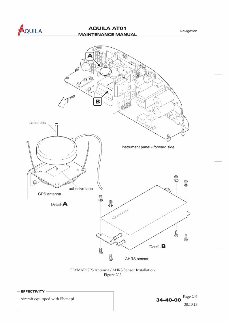
MAINTENANCE MANUAL
AQUILA AT01A
34-40-00Page 204
EFFECTIVITY
Aircraft equipped with FlymapL
Navigation
30.10.13
instrument panel - forward side
FLYMAP GPS Antenna / AHRS Sensor InstallationFigure 202
ADetail-
BDetail-
cable ties
adhesive tape
A
B
GPS antenna
AHRS sensor

MAINTENANCE MANUAL
AQUILA AT01A
34-40-00
Page 205
Navigation
EFFECTIVITY
Aircraft equipped with FlymapL
30.10.13
(3) Remove the plugs/caps from the sensor ports and the pressure lines.Reconnect pitot and static pressure lines to the respective sensor port.Make sure that the pressure lines are properly connected to the correct port and secure theconnections with cable ties.
(4) Connect the required plug connector at the sensor. Make sure that the plug is properlyconnected.
(6) Install glare shield (refer to 31-10-00).(7) Reconnect battery (refer to 24-30-00).(8) Perform a functional check of the unit.
FlymapL
5.
A. When the power is connected to the it will automatically switch on. After a short startupperiod the map will appear. If in the centre of the screen a red cross appears together with theword GPS, no GPS signal is detected. Check GPS antenna connection and make sure that the GPSantenna has full view to the open sky without any obstacles.
If an aircraft symbol is displayed on the screen at the current location and the map isautomatically align either with the aircraft in the centre (for North Up display) or with the aircraftnear to the bottom of the screen (for Course Up display), the system is working properly (refer tothe FlymapL Operating Manual for additional functions of the FlymapL display system).
A flight test is recommended after FlymapL unit or AHRS sensor installation to ensurethe proper functioning of the system.
Inspection/Check
NOTE:
(5) Perform a pitot-static system leak test (refer to 34-11-00).

MAINTENANCE MANUAL
AQUILA AT01A

MAINTENANCE MANUAL
AQUILA AT01A
34-45-00
Page 201
EFFECTIVITY
Aircraft equipped with FLARM Collision WarningSystem 30.10.13
Navigation
COLLISION WARNING SYSTEM – MAINTENANCE
1.
A. This section covers miscellaneous avionic equipment. This includes the FLARM Collision WarningSystem. The scope of maintenance is limited to the removal and installation of the components.For further information on the equipment, refer to the appropriate publications of the equipmentmanufacturer. For overhaul and repair, the manufacturer of the equipment has to be consulted.
B. The FLARM receives position and motion information from an internal 16 channel GPS receiverwith an external antenna. The predicted flight path is calculated by FLARM and the informationtransmitted by radio as low-power digital burst signals at one-second intervals. Provided thatthey are within receiving range, the signals are received by other aircraft also equipped withFLARM. The incoming signal is compared with the flight path predicted by calculation for thesecond aircraft. At the same time, FLARM compares the predicted flight path with known data onobstacles, including electric power lines, radio masts and cable cars. If FLARM determines the riskof dangerous proximity to one or more aircraft or obstacles, the unit gives the pilot warning of thegreatest danger at that moment. The warning is given by a whistle sound (beep) and bright lightemitting diodes (LED). The display also gives indication of the threat level, plus the horizontaland vertical bearing to the threat. The GPS and collision information received from other aircraftcan also be made available for other equipment like the FLYMAP via a serial data output interface.For more information, refer to the Operating Manual of the FLARM Collision Warning Unit, latestrevision.
The electrical circuit of the FLARM system is protected by a circuit breaker labeled “FLARM”. TheGPS signals are received by an antenna which is mounted on a bracket attached to the RH sidesupport plate of the instrument panel. The radio antenna for the transmission of the FLARMsignals to other aircrafts equipped with FLARM is attached to the rear side of the instrument panelbetween the circuit breakers and the engine instruments and is protected by a rubber sleeve. TheFLARM unit itself is mounted underneath the base plate of the instrument panel in the leftsection. The LED display unit of the FLARM system is located in the left section of the instrumentpanel.
C. For additional maintenance information on the FLARM unit, refer to the FLARM InstallationManual, latest revision. For the installation of software or database updates, refer to thedocumentation and manuals of the manufacturer of the FLARM Collision Warning System.
General
2. (Ref. Fig. 201)
A. Remove FLARM Unit(1)
Mark the removed cables, as required, and the installation position of the unit.(5) Remove both attachment screws of the FLARM unit. While removing the attachment screw
secure the FLARM unit by hand to prevent it from falling down.(6) Carefully remove the unit.
FLARM Unit Removal/Installation
Ensure electrical power to aircraft is OFF.(2) Disconnect battery (refer to 24-30-00).(3) Remove glare shield (refer to 31-10-00).(4) Disconnect all plug connectors and cables.

MAINTENANCE MANUAL
AQUILA AT01A Navigation
34-45-00Page 202
EFFECTIVITY
Aircraft equipped with FLARM Collision WarningSystem 30.10.13
FLARM Components InstallationFigure 201
instrument panel - forward side
B
ADetail-
BDetail-
cable ties
adhesive tape
Aradio antenna
GPS antenna
unit
MAINTENANCE MANUAL
AQUILA AT01A Navigation
34-45-00
Page 203
EFFECTIVITY
Aircraft equipped with FLARM Collision WarningSystem 30.10.13
B. Install FLARM Unit(1) Hold the unit correctly aligned at its installation position and install both attachment screws
from the inside the instrument panel.(2) Connect all required plug connectors and cables to the unit.
Make sure that all plugs and cables are properly connected.(3)
3.
A. Remove FLARM GPS Antenna(1)
(4) Disconnect antenna cable from FLARM unit and remove the cable ties.(5) Mark the installation position and remove the cable ties of the antenna attachment.(6) Carefully take out the antenna which is additionally attached to the installation bracket by a
Velcro tape.
B. Install FLARM GPS Antenna(1) Install a Velcro tape at the bottom of the antenna and on its installation bracket (if applicable).(2) Attach antenna to the installation bracket with its Velcro fastener in its correct installation
position as previously marked. Secure with 2 cable ties.(3) Install the antenna cable properly and connect it to the FLARM unit.(4)
4.
A. Remove FLARM Radio Antenna(1)
(4) Disconnect antenna cable from FLARM unit and remove the cable ties.(5) Mark the installation position and remove the cable ties of the antenna attachment.(6) Carefully take the antenna out of the instrument panel interior.
B. Install FLARM Radio Antenna(1) Install the rubber protection sleeve on the antenna (if applicable).(2) Install the antenna in its installation holders on the rear side of the instrument panel as
previously marked. Secure with cable ties.(3) Install the antenna cable properly and connect it to the FLARM unit.(4)
Install glare shield (refer to 31-10-00).(4) Reconnect battery (refer to 24-30-00).(5) Perform a functional check of the unit.
Ensure electrical power to aircraft is OFF.(2) Disconnect battery (refer to 24-30-00).(3) Remove glare shield (refer to 31-10-00).
Install glare shield (refer to 31-10-00).(5) Reconnect battery (refer to 24-30-00).(6) Perform a functional check of the unit.
Ensure electrical power to aircraft is OFF.(2) Disconnect battery (refer to 24-30-00).(3) Remove glare shield (refer to 31-10-00).
Install glare shield (refer to 31-10-00).(5) Reconnect battery (refer to 24-30-00).(6) Perform a functional check of the unit.
GPS Antenna Removal/Installation (Ref. Fig. 201)
Radio Antenna Removal/Installation

MAINTENANCE MANUAL
AQUILA AT01A
34-45-00Page 204
EFFECTIVITY
Aircraft equipped with FLARM Collision WarningSystem 30.10.13
5.
A. Remove FLARM Display Unit(1)
(4) Disconnect plug connector from display unit and mark it as required.(5) Carefully remove the display unit with suitable tools/means. The display unit is bonded to
the instrument panel with double-sided adhesive tape (see also the FLARM CollisionWarning System Operating Manual).
(6) Remove adhesive residue from instrument panel with acetone.
B. Install FLARM Display Unit(1) Remove the protective film from the double-sided adhesive tape on the rear side of the
FLARM display unit and install it in the instrument panel in its correct installation position.(2) Connect plug connector on the rear side of the display unit. Make sure that the plug is
properly connected.(3)
Display Unit Removal/Installation
Ensure electrical power to aircraft is OFF.(2) Disconnect battery (refer to 24-30-00).(3) Remove glare shield (refer to 31-10-00).
Install glare shield (refer to 31-10-00).(4) Reconnect battery (refer to 24-30-00).(5) Perform a functional check of the unit.
Navigation
MAINTENANCE MANUAL
AQUILA AT01A
34-50-00
Page 201
EFFECTIVITY
Aircraft equipped with Bendix/KingKX 125 / KT 76A/C 30.10.13
Navigation
DEPENDENT POSITIONING DETERMINING - MAINTENANCE PRACTICES
1.
A. This section covers that portion of the system which provides information to determine positionand is mainly dependent on ground installations. This includes the NAV portion of theBendix/King KX 125 transceiver and the Bendix/King KT 76A/C transponder.
B. Bendix/King KX 125 RadioFor navigation purposes, data from ground stations can be received and indicated with thenavigation portion of the Bendix/King KX 125 radio. The NAV signals are received by the NAVantenna located in the fuselage belly behind the baggage compartment. This antenna is embeddedin the fuselage shell structure and is thus maintenance-free. However, if any maintenance shouldbe required, contact the manufacturer.For removal/installation of the KX 125 unit, refer to 23-10-00.
C. Bendix/King KT 76A/C TransponderThe KT 76A/C transponder is a radio transmitter and receiver which operates on radarfrequencies. Receiving ground radar interrogations at 1030 MHz, it returns a coded response ofpulses to ground-based radar on a frequency of 1090 MHz.The KT 76A/C unit is mounted in the instrument panel in the avionics column.The transponder antenna is installed on the bottom of the cabin, below the co-pilot's seat.
efer to theKT 76C Installation Manual, P/N 006-10545-0001, latest revision, and to theKT 76A/C Maintenance Manual, P/N 006-15545-0002, latest revision.
2.
A. Remove KT 76A/C Transponder Unit(1)
B. Install KT 76A/C Transponder Unit(1)
(3)
General
Bendix/King KT 76A/C Transponder Removal/Installation
D. For additional maintenance information on the KT 76A/C transponder, r
Ensure electrical power to aircraft is OFF.(2) Insert a 3/32" hex wrench into the jackscrew access hole on the face of the transponder unit
and turn counterclockwise until locking paw releases unit from rack.(3) Carefully pull unit out of the mounting tray.
Ensure all required plugs and cables at back of the mounting tray are properly connected.(2) Carefully slide unit forward into the mounting tray until contact is made by the pins and
then push the unit firmly into the mounting tray until fully engaged.Insert a 3/32" hex wrench into the mounting hole on the lower right-hand side of the unit andengage hex bolt (max. torque 1,7Nm [15 in.lbs]). Turn wrench clockwise until locking pawsecures unit to mounting tray.
(4) Conduct a functional test of the unit.

MAINTENANCE MANUAL
AQUILA AT01A
3.
A. Remove Transponder Antenna(1) Ensure electrical power to aircraft is OFF.(2) Remove access/inspection plate 211 BB (refer to 25-12-00) to gain access to the transponder
antenna.(3) Remove nuts and washers securing transponder antenna to fuselage.
The connected antenna cable prevents the antenna from falling away from theaircraft.
(4) From outside the aircraft, disconnect antenna cable at connector and remove antenna fromaircraft.
B. Install Transponder Antenna(1) From outside the aircraft, connect antenna cable to the transponder antenna.(2) From inside the fuselage, insert antenna studs through mounting holes and position the
backing plate.(3) Install washers and nuts securing transponder antenna to fuselage skin.(4) Seal the antenna to fuselage using a good quality electrical sealant (Sikaflex-221 or equivalent,
silicone-free).(5) Install access/inspection plate 211 BB (refer to 25-12-00).
Transponder Antenna Removal/Installation
NOTE:
34-50-00Page 202
EFFECTIVITY
Aircraft equipped with Bendix/KingKX 125 / KT 76A/C 30.10.13
Navigation

MAINTENANCE MANUAL
AQUILA AT01A Navigation
34-50-00
Page 201
EFFECTIVITY
Aircraft equipped with Garmin Avionics
30.10.13
DEPENDENT POSITIONING DETERMINING - MAINTENANCE
1.
A. This section covers that portion of the system which provides information to determine positionand is mainly dependent on ground installations. This includes the VOR/ILS receiver portion ofthe GNS 430(W) / GNS 530(W) / GTN 650 navigation management system (NMS), the VOR/ILSreceiver portion of the SL30 COM/NAV transceiver as well as the Garmin GTX 327 / GTX 328 /GTX 330 mode S transponder.
B. Garmin GNS 430(W) / GNS 530(W) / GTN 650 SystemThe GNS 430(W) / GNS 530(W) / GTN 650 system is a fully integrated, panel mounted instrument,which contains a VHF communications transceiver, a VOR/ILS/GS receiver and a GPS navigationcomputer. The primary function of the VOR/ILS receiver portion of the equipment is to receiveand demodulate VOR, localizer and glideslope signals. NAV/LOC/GS signals are received by theVOR/LOC antenna located in the fuselage belly behind the baggage compartment. This antennais embedded in the fuselage shell structure and is therefore maintenance-free. However, if anymaintenance should be required, contact the manufacturer.For further information on the GNS 430(W) / GNS 530(W) / GTN 650 unit, refer to 23-10-00.
C. Garmin SL30 COM/NAV TransceiverThe SL30 is a combination of a VHF communications transceiver and a VHF navigation receiverwhich includes VOR, localizer and glideslope receiver, a built-in course deviation indicator and anindependent voice-activated intercom.The VOR, localizer and glideslope receivers provide 200 channels with a frequency range of 108 to117.95 MHz for VOR, 108 to 111.95 for localizer and 329.15 to 335 MHz for glideslope reception.VOR/LOC/GS signals are received by the VOR/LOC antenna which is integrated into the lowerfuselage shell structure behind the baggage compartment. This antenna is maintenance free andcannot be removed. However, if any maintenance or repair is necessary, contact the manufacturer.For further information on the SL30 unit, refer to 23-10-00.
D. Garmin GTX 327 TransponderThe Garmin GTX 327 transponder, located in the middle avionics panel, receives interrogationsfrom a ground-based secondary radar transmitter and transmits aircraft identification to the airtraffic control center via Mode A transmissions and altitude information via Mode C.
Refer to the Garmin GTX 327 Installation Manual, P/N 190-00187-02, latest revision, for additionalmaintenance information on the GTX 327 transponder system.
E. Garmin GTX 328 Mode S TransponderThe GTX 328 transponder is a radio transmitter and receiver that operates on radar frequencies,receiving ground radar or TCAS interrogations at 1030 MHz and transmitting a coded response ofpulses to ground based radar on a frequency of 1090 MHz. The GTX 328 is equipped with IDENTcapability that activates the special position identification (SPI) pulse for 18 seconds. The GTX 328replies to Mode A, Mode C and Mode S all-call interrogation. As a level 2 transponder, the GTX328 provides a downlink of aircraft information. Ground stations can interrogate Mode Stransponders individually using a 24-bit ICAO Mode S address which is unique to that particular
General
The transponder antenna is installed on the bottom of the cabin, below the co-pilot's seat.

MAINTENANCE MANUAL
AQUILA AT01A
34-50-00Page 202
Navigation
EFFECTIVITY
Aircraft equipped with Garmin Avionics
30.10.13
aircraft. In addition, ground stations may interrogate a GTX 328 for its transponder datacapability and aircraft flight ID which may be the registration number or another call sign.The electrical circuit of the GTX 328 Mode S transponder is protected by a circuit breaker labeled“Transponder”. The transponder antenna is installed on the bottom of the cabin, below the co-pilot's seat.
For a complete description of the GTX 328, refer to the Pilot's Guide of the GTX 328,P/N 190-00420-03, latest revision. For additional maintenance information on the GTX 328 Mode Stransponder, refer to GTX 328 Installation Manual, P/N 190-00420-04, latest revision.
F. Garmin GTX 330 Mode S TransponderThe Garmin GTX 330 is a panel-mounted non-diversity Mode S transponder working like a radiotransmitter and receiver that operates on radar frequencies, receiving ground radar or TCASinterrogations at 1030 MHz and transmitting a coded response of pulses to ground based radar ona frequency of 1090 MHz. The GTX 330 is equipped with IDENT capability that activates thespecial position identification (SPI) pulse for 18 seconds. The GTX 330 replies to Mode A, Mode Cand Mode S all-call interrogation. As a level 2 transponder, the GTX 330 provides downlink ofaircraft information. Ground stations can interrogate Mode S transponders individually using a24-bit ICAO Mode S address, which is unique to that particular aircraft. In addition, groundstations may interrogate a GTX 330 for its transponder data capability and aircraft flight ID whichmay be the registration number or another call sign.The electrical circuit of the GTX 330 mode S transponder is protected by a circuit breaker labeled“Transponder”. The transponder antenna is installed on the bottom of the cabin, below the co-pilot's seat.
For a complete description of the GTX 330, refer to the Pilot's Guide of the GTX 330,P/N 190-00207-00, latest revision. For additional maintenance information on the GTX 330 Mode Stransponder, refer to GTX 330 Installation Manual, P/N 190-00207-02, latest revision.
2.
A. Remove Garmin GTX 327 / GTX 328 / GTX 330 Transponder(1)
B. Install Garmin GTX 327 / GTX 328 / GTX 330 Transponder
BE SURE NOT TO OVERTIGHTEN THE UNIT INTO THE RACK. APPLICATIONOF HEX WRENCH TORQUE EXCEEDING 1,7 NM [15 IN.LBS] CAN DAMAGETHE LOCKING MECHANISM.
It may be necessary to insert the hex wrench into the access hole on the unit faceand rotate the mechanism 90° counterclockwise to ensure correct position prior toplacing the unit in the rack.
(1) Slide unit carefully straight in the rack until it stops, about 1 inch short of the final position.
Garmin GTX 327 / GTX 328 / GTX 330 Transponder Removal/Installation
CAUTION:
NOTE:
Ensure electrical power to aircraft is OFF.(2) Insert a 3/32" hex wrench into the jackscrew access hole on the face of the transponder unit
and turn counterclockwise until locking paw releases unit from rack.(3) Carefully pull unit out of the mounting tray.

MAINTENANCE MANUAL
AQUILA AT01A
34-50-00
Page 203
Navigation
EFFECTIVITY
Aircraft equipped with Garmin Avionics
30.10.13
(2) Insert a 3/32 hex wrench into the access hole at the bottom of the unit face and engage hexbolt.
(3) Turn wrench clockwise until the unit is secured in the rack.(4) Carry out a functional test of the installed unit in accordance with section 1.9 of the GTX 327
Installation Manual respectively section 3.4 of the GTX 328 / GTX 330 Installation Manual.
3.
A. Remove Transponder Antenna(1) Ensure electrical power to aircraft is OFF.(2) Remove access/inspection plate 211 BB (refer to 25-12-00) to gain access to the transponder
antenna.(3) Remove nuts and washers securing transponder antenna to fuselage.
The connected antenna cable prevents the antenna from falling away from theaircraft.
(4) From outside the aircraft, disconnect antenna cable at connector and remove antenna fromaircraft.
B. Install Transponder Antenna(1) From outside the aircraft, connect antenna cable to the transponder antenna.(2) From inside the fuselage, insert antenna studs through mounting holes and position the
backing plate.(3) Install washers and nuts securing transponder antenna to fuselage skin.(4) Seal the antenna to fuselage using a good quality electrical sealant (Sikaflex-221 or equivalent,
silicone-free).(5) Install access/inspection plate 211 BB (refer to 25-12-00).
Transponder Antenna Removal/Installation
NOTE:

MAINTENANCE MANUAL
AQUILA AT01A

MAINTENANCE MANUAL
AQUILA AT01A
CHAPTER 51
STRUCTURES

MAINTENANCE MANUAL
AQUILA AT01A

MAINTENANCE MANUAL
AQUILA AT01A
Page 151 - TOC
TABLE OF CONTENTS
ChapterSection
STRUCTURES - GENERAL..............................................................................51-00-00 1Introduction 51-00-00 1General Description 51-00-00 1
FIBERGLASS LAMINATE STRUCTURES - MAINTENANCE...................51-10-00 201General 51-10-00 201Inspection Methods 51-10-00 201Damage Classification 51-10-00 202
REPAIR OF FIBERGLASS LAMINATE COMPONENTS............................51-20-00 201General 51-20-00 201Repair Requirements 51-20-00 201Approved Fiberglass Laminate Repair Materials 51-20-00 202Tools, Equipment and Material 51-20-00 202Material Data Sheet 51-20-00 204Repair of Sandwich Components 51-20-00 212Repair of Non-Structural Laminate Components 51-20-00 218Exterior Finish 51-20-00 219
Title Subject Page
Structure Classes 51-00-00 2
Structures
30.10.13

MAINTENANCE MANUAL
AQUILA AT01A

MAINTENANCE MANUAL
AQUILA AT01A
51-00-00
STRUCTURES - GENERAL
1.
A. This chapter provides a general overview of the structural design. The chapter containsinformation and procedures applicable to all composite repairs as well as information andprocedures for aircraft painting and priming.
B. Please contact AQUILA Aviation GmbH for support in case damage to the aircraft structure thecause of which is unknown or suspect, and prior to major repairs to obtain detailed information.
AQUILA Tel.: +49(0) 33731 707-0Flugplatz Fax.: +49(0) 33731 707-1114959 SchönhagenGermany
2.
Most of the aircraft structure is made from composite materials. Glass-fiber (GFRP) and carbon-fibermaterials (CFRP) are used which are bedded in an epoxy resin matrix. The aircraft structure consists ofmonolithic GFRP or CFRP shells and structure components as well as sandwich shells which have arigid foam core.
A. FuselageThe fuselage with the vertical and horizontal stabilizers represents one component. Including thevertical stabilizer, it consists of two half-shells. The fuselage portion of the half-shells is made fromsolid (non-foam) fiberglass laminate, the vertical stabilizer has a sandwich structure. The fuselageGFRP skin is reinforced by four carbon-fiber stringers, arranged lengthwise through the entirefuselage.Four ring frames and a baggage compartment frame provide support to the fuselage shells in thetail section. A landing gear bulkhead, a seat bulkhead and a side-force bulkhead carry singleloads.The front of fuselage ends with the firewall which includes the metal fittings for supporting theengine mount. The firewall, constructed of a GFRP/CFRP composite sandwich, has a fireprotection lining which consists of an especially fire-resistant ceramic fleece anda stainless-steel sheet.The landing gear bulkhead which together with the seat bulkhead supports the main landinggear struts, is complemented upwards through a compact CFRP/GFRP roll-over bar.
B. WingsThe plan view of the wing is a triple trapezoid that is complemented by a winglet at its end.The wing has top and bottom shells, constructed of a GFRP composite sandwich and locallyreinforced by CFRP straps. The aircraft has a one-piece wing because the wing spar ismanufactured in one piece and is continuous from wing tip to wing tip. The I-section spar hascaps made from unidirectional carbon-fiber and a GFRP composite sandwich web.Each wing half ends inboard with a front root rib and a rear root rib, which are mounted to thefuselage center section with a bolt apiece.
Introduction
General Description
Aviation GmbH
on the front side
Structures
30.10.13
Page 1
MAINTENANCE MANUAL
AQUILA AT01A
51-00-00Page 2
30.10.13
AQUILA AT01 Primary StructureFigure 01
The four lateral force bolts are inserted from the cabin through the fuselage bushings into thewing bolt casings and secured axially with screws.The outboard end of the wing has a winglet with the NAV lights and the fuel tank vents. Theinboard portion of the wings contains an integral fuel tank with a capacity of 60 liters per wing.The ailerons are located at the wing trailing edge near the wing tips. They are of a semi-monocoque sandwich construction consisting of rigid foam core and glass and carbon fiber layers.The flaps, of a semi-monocoque CFRP sandwich construction, are mounted to the trailing edge ofeach wing between the inboard end of the ailerons and the fuselage.They are attached to the wings using hinges that are located below the bottom of the wing. Thisresults in the gap between wing trailing edge and flap leading edge and increases as the flapextend. This increases the lift force and simultaneously the drag force.
C. StabilizersThe vertical and horizontal stabilizers, as well as the elevator and rudder are of semi-monocoquedesign consisting of shells fabricated from GFRP sandwich reinforced with CFRP.The vertical and the horizontal stabilizers have a main spar and a rear shear web with integratedhinges.The horizontal stabilizer is molded to the fuselage and cannot be removed.The VHF NAV/COM antenna is an integral part of the vertical stabilizer.
3.
A. Primary StructureThese parts are important for the structural integrity of the aircraft. For example: fuselage, wing,stabilizer and control surface shells, spars, frames, joints, brackets.
B. Secondary StructureThese parts are not important for the structural integrity of the aircraft. For example: panels,covers, access plates, fairings.
Structure Classes
Structures
MAINTENANCE MANUAL
AQUILA AT01A
51-10-00
Page 201
30.10.13
FIBERGLASS LAMINATE STRUCTURES - MAINTENANCE
1.
A. This section contains maintenance information and procedures such as investigation and damageclassification applicable to aircraft fiberglass laminate structure components.
2.
A. Visual InspectionMost damage to a fiberglass-laminated structure will be visually detectable. A wide variety ofcomponent surface discontinuities such as scratches, cracks, dimples, dents and creases mayindicate damage. The use of optical aids such as flashlights, inspection mirrors and simplemagnifiers is recommended. To allow remote visual inspection of internal surfaces or otherinaccessible areas, a borescope can be used.If the exterior surface is damaged, e.g. paint cracks, always assume that the underlying structuremay also be damaged. To determine the extent of composite damage, other inspection methodsmay be additionally required.
B. Tap TestingTap testing is used for a quick evaluation of composite surfaces to detect the presence ofdelamination or debonding. The tap testing procedure consists of lightly tapping the surface ofthe part with a coin, special hammer or any another suitable object. The acoustic response iscompared with that of a known good area. Areas of disbonding or delamination will sound “flat”or “dead”, undamaged areas should sound sharp and clear. The tap testing method should beused in conjunction with the exploration method.
C. Ultrasonic InspectionUltrasonic inspection can easily detect subsurface discontinuities, such as cracks, shrinkagecavities, bursts, pores, delaminations and porosity. This method is based on the fact that theamount of reflection that occurs when a sound wave strikes an interface depends largely on thephysical state of the materials forming the interface and to a lesser extent on the specific physicalproperties. The ultrasonic instrument generates an ultrasonic pulse, detects and amplifies thereturning echo and displays the detected signal on a cathode ray tube or similar display. Forspecific inspection procedures refer to manufacturer publications of the ultrasonic test equipmentused. If a flaw is detected, further exploration of the suspect composite area as described below isrequired.
D. ExplorationExploration is an extension of visual inspection, but requires removal of the facing coat. Theexploration method must be employed when subsurface damage has been detected by tap testing,during ultrasonic inspection or to determine the precise extend of damage.
General
Inspection Methods
light
Structures
MAINTENANCE MANUAL
AQUILA AT01A
51-10-00Page 202
3.
A. Damage to fiberglass laminate structures can be divided into four classes:
(1) Damage Class 1Severe, extensive damage that requires partial component restoration or general componentreplacement.
(2) Damage Class 2Damage to primary or secondary structures with sandwich penetration such as holes orfractures. Both sides of sandwich penetrated and the laminate on both sides must be repairedand the core section replaced.
(3) Damage Class 3Damage only to outer laminate layers on one side of a sandwich construction without or onlyminor gouging of core material.
(4) Damage Class 4Damage to outer surface of composite structures such as superficial scars, scratches, surfaceabrasion or erosion. No holes or laminate fractures.
Damage Classification
B. Minor DamagesOnly the damages listed below can be considered as small damages and repaired by qualifiedpersonnel without a repair scheme which has been approved by the manufacturer. In general alldamages in force introduction or reinforced areas (i.e. spars, ribs) have to be carried out bycertified repair stations for composite aircraft structure works.
(1) Any damages limited to varnish or filler.
(2) Damages not exceeding the permissible dimensions of holes, dents and cracks that are listedin the following table:
(3) Damages not affecting glass and carbon rovings or carbon tapes in the primary structure.
(4) No class 1 damages and no damages in critical areas. Refer to figure 201 for an overview ofthe main critical areas of the aircraft.
Structures
30.10.13
Part Average hole or dent diam. Crack length
Front fuselage (cockpit) 75 mm [3 in.]50 mm [2 in.]
Rear fuselage (tail boom) 25 mm [1 in.] 50 mm [2 in.]
Wing 75 mm [3 in.] 100 mm [4 in.]
Stabilizers
Flap, Aileron
Rudder, Elevator
25 mm [1 in.]
25 mm [1 in.]
25 mm [1 in.]
50 mm [2 in.]
50 mm [2 in.]
50 mm [2 in.]
Cowling, Fairings 75 mm [3 in.] 100 mm [4 in.]

MAINTENANCE MANUAL
AQUILA AT01A
51-10-00
Page 203
30.10.13
Structures
Damages - Critical AreasFigure 201
4500
1000
1350
350
550
200
200
200
100
80
wing root area
wing root area
wing root area
wing spar area
stabilizer root area
stabilizer root area
stabilizer spar area
roll-over barstrip around the
canopy frame
fuel tank

MAINTENANCE MANUAL
AQUILA AT01A

MAINTENANCE MANUAL
AQUILA AT01A
REPAIR OF FIBERGLASS LAMINATE COMPONENTS
1.
A. This section covers required information to complete successful repairs to aircraft components thatare made from fiberglass laminate. Necessary repair data, such as ply lay-up and ply orientationfor various areas, as well as repair materials and procedures are provided. Not included aregeneral practices used during most composite repairs, such as cleaning and preparing thedamaged area, proper preparation of materials, mixing and applying resin or proper curing therepair. Personnel must be familiar with these practices prior to attempting fiberglass compositerepairs on this aircraft.
2.
A. The following requirements must be met:(1) Repairs for which no description is given in this chapter may only be carried out in
accordance with a repair scheme which must be approved in accordance with the proceduresestablished by the competent certifying authority.
(2) Only damages classified as minor damages (refer to 51-10-00) can be repaired by qualifiedpersonnel
(5) Repairs must be completed by competent technicians trained in fiberglass composite repair.(6) Before beginning a repair make sure all required tools, equipment and materials are ready. If
you are not familiar with the proper use of all the repair tools, never attempt a fiberglasscomposite repair.
(7) Use the approved materials outlined in this section . Prepare materials in accordancewith information given in this manual and manufacturer instructions.
(8) Review material safety data sheets for material to be used. Observe shelf life.(9) Repairs should be made in a clean, temperature controlled environment. Optimal repair
temperature lies between 16°C and 27°C (60°F - 80°F) with 50% relative humidity or less.(10) It is recommended to prepare a test specimen during actual repair which can be subjected to
a destructive test to establish the quality of the adhesive bond in the repaired part.(11) To preserve the good aerodynamic characteristics of the aircraft smooth and precisely contour
repaired surfaces.
B. Safety Precautions(1) Read and adhere to all manufacturer instructions, warnings and cautions on the materials
and chemicals used.(2) Sanding fiberglass laminates results in a fine dust that may cause skin and/or respiratory
irritation unless suitable protection is used.(3) Never handle glass-fabric materials with bare hands, use clean cotton or rubber gloves.
General
Repair Requirements
without a repair scheme which has been approved by the manufacturer orcognizant regulatory authority.
(3) In general all damages in force introduction or reinforced areas (i.e. spars, ribs) have to becarried out by certified repair stations for composite aircraft structure works or properlycertified and trained persons.
(4) Class 4 damages (refer to 51-10-00) don’t have to be repaired immediately after detection ifadequately protected from environmental conditions (e.g. adhesive tape).
only
(12) All control surfaces have to be checked for weight and control surface moment after repair.
51-20-00
Page 201
Structures
30.10.13
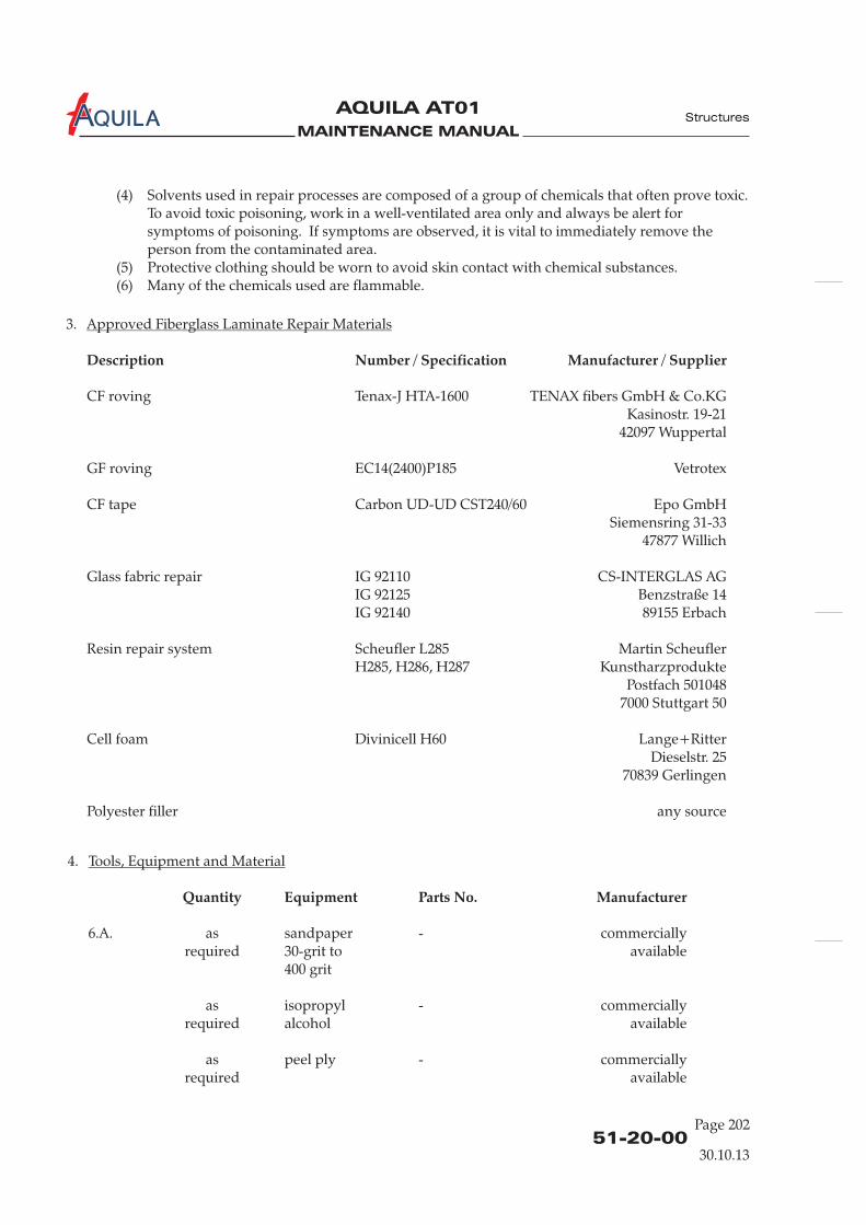
MAINTENANCE MANUAL
AQUILA AT01A
4.
6.A. as sandpaper - commerciallyrequired 30-grit to available
400 grit
as isopropyl - commerciallyrequired alcohol available
as peel ply - commerciallyrequired available
Tools, Equipment and Material
Quantity Equipment Parts No. Manufacturer
51-20-00Page 202
3.
CF roving Tenax-J HTA-1600 TENAX fibers GmbH & Co.KGKasinostr. 19-21
42097 Wuppertal
GF roving EC14(2400)P185 Vetrotex
CF tape Carbon UD-UD CST240/60 Epo GmbHSiemensring 31-33
47877 Willich
Glass fabric repair IG 92110 CS-INTERGLAS AGIG 92125 Benzstraße 14IG 92140 89155 Erbach
Resin repair system Scheufler L285 Martin ScheuflerH285, H286, H287 Kunstharzprodukte
Postfach 5010487000 Stuttgart 50
Cell foam Divinicell H60 Lange+RitterDieselstr. 25
70839 Gerlingen
Polyester filler any source
Approved Fiberglass Laminate Repair Materials
Description Number / Specification Manufacturer / Supplier
Structures
30.10.13
(4) Solvents used in repair processes are composed of a group of chemicals that often prove toxic.To avoid toxic poisoning, work in a well-ventilated area only and always be alert forsymptoms of poisoning. If symptoms are observed, it is vital to immediately remove theperson from the contaminated area.
(5) Protective clothing should be worn to avoid skin contact with chemical substances.(6) Many of the chemicals used are flammable.

MAINTENANCE MANUAL
AQUILA AT01A
as release film - commerciallyrequired available
as hot glue - commerciallyrequired available
as cotton cloth - commerciallyrequired available
1 mixing container - commerciallyavailable
as stir sticks - commerciallyrequired available
1 scale - commerciallyavailable
1 pair gloves - commerciallyavailable
8.A. as masking tape - commerciallyrequired 2-inch available
as sandpaper - commerciallyrequired 240-grit to available
360-grit
as cotton cloth - commerciallyrequired available
as isopropyl - commerciallyrequired alcohol available
as 2k epoxy primer DuPontrequired activator XK206
thinner EV301
8.B.
as coating PUR EV310 DuPontreqired activator PUR EV313
thinner PUR EV303
LE2001
as cotton cloth - commerciallyrequired available
as isopropyl - commerciallyrequired alcohol available
Quantity Equipment Parts No. Manufacturer
51-20-00
Page 203
Structures
30.10.13

MAINTENANCE MANUAL
AQUILA AT01A
51-20-00Page 204
Item No. Layers Description Remarks
1 1
1
1
1
1
1
1
1
1
1
1
1
1
2
2
overall
rigid foam
fr. wind. up to end of tail
stringer covering
overall
up to baggage bulkhead
sidewalls only
sidewalls only
bottom only
bottom only
2
2
3
3
3
4
4
4
5
5
6
7
7
8
9
10
11
12
13
14
15
16
17
18
19
20
21
22
23
Interglas 92110
Interglas 92110
Interglas 92110
Interglas 92125
Interglas 92125
Interglas 92125
Interglas 92125
Interglas 92125
Interglas 92125
Interglas 92125
Interglas 92125
DH 60-06
Interglas 92140
Interglas 92140
Interglas 92140
Interglas 92140
width 80 mm
width 100 mm
-
CST 240/60 unidirectional
CST 240/60 unidirectional
CST 240/60 unidirectional
CST 240/60
CST 240/60
CST 240/30
CST 240/30
5.
A. The material data sheet in combination with figure 202 and 203 should be used for.
The item numbers give the order in which the layers are applied.
Material Data Sheet
information onply lay-up and ply orientation
Structures
30.10.13

MAINTENANCE MANUAL
AQUILA AT01A
Fuselage Ply Lay-UpFigure 202 (1)
51-20-00
Page 205
1
2
3
4
5
6
7
9
8
Structures
30.10.13
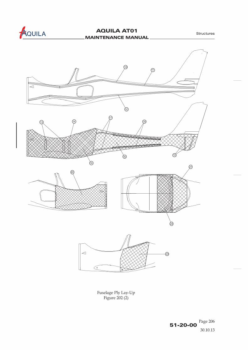
MAINTENANCE MANUAL
AQUILA AT01A
51-20-00Page 206
Fuselage Ply Lay-UpFigure 202 (2)
10
17
1813
20
21
22
23
15
14
11
16
19
12
Structures
30.10.13
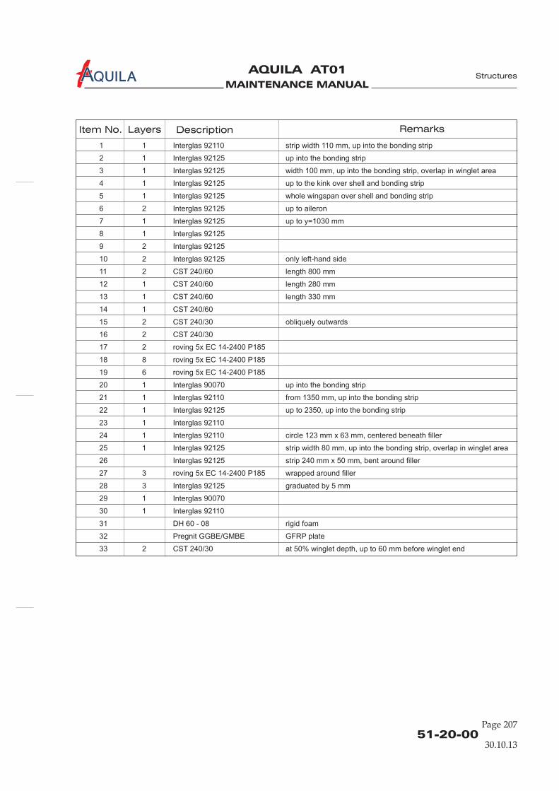
MAINTENANCE MANUAL
AQUILA AT01A
51-20-00
Page 207
Structures
30.10.13
Item No. Layers Description Remarks
1 1 Interglas 92110 strip width 110 mm, up into the bonding strip
2 1 Interglas 92125 up into the bonding strip
3 1 Interglas 92125 width 100 mm, up into the bonding strip, overlap in winglet area
4 1 Interglas 92125 up to the kink over shell and bonding strip
5 1 Interglas 92125 whole wingspan over shell and bonding strip
6 2 Interglas 92125 up to aileron
7 1 Interglas 92125 up to y=1030 mm
8 1 Interglas 92125
9 2 Interglas 92125
10 2 Interglas 92125 only left-hand side
11 2 CST 240/60 length 800 mm
12 1 CST 240/60 length 280 mm
13 1 CST 240/60 length 330 mm
14 1 CST 240/60
15 2 CST 240/30 obliquely outwards
16 2 CST 240/30
17 2 roving 5x EC 14-2400 P185
18 8 roving 5x EC 14-2400 P185
19 6 roving 5x EC 14-2400 P185
20 1 Interglas 90070 up into the bonding strip
21 1 Interglas 92110 from 1350 mm, up into the bonding strip
22 1 Interglas 92125 up to 2350, up into the bonding strip
23 1 Interglas 92110
24 1 Interglas 92110 circle 123 mm x 63 mm, centered beneath filler
25 1 Interglas 92125 strip width 80 mm, up into the bonding strip, overlap in winglet area
26 Interglas 92125 strip 240 mm x 50 mm, bent around filler
27 3 roving 5x EC 14-2400 P185 wrapped around filler
28 3 Interglas 92125 graduated by 5 mm
29 1 Interglas 90070
30 1 Interglas 92110
31 DH 60 - 08 rigid foam
32 Pregnit GGBE/GMBE GFRP plate
33 2 CST 240/30 at 50% winglet depth, up to 60 mm before winglet end
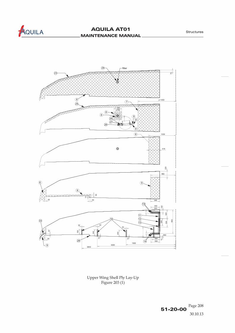
MAINTENANCE MANUAL
AQUILA AT01A
23
8
26
2726
8
16
28
14
11
12
13
14
33
9
8
9
8
88
8
7
filler
25
8
8
24
300
1030
416
960
36003000
1900
850
50
50
50
30 3030
300
300
350
350
346
160
70
220
50
67
150
240
10
1010
240
10
100
320
330 900
280
y=1450
30.10.1351-20-00
Page 208
Structures
Upper Wing Shell Ply Lay-UpFigure 203 (1)

MAINTENANCE MANUAL
AQUILA AT01A
30.10.1351-20-00
Page 209
Structures
31
31
17
84
29
528
10001350
30
1350
8
2350
14
8
200
550
100
4100
4500
45050
1750
6316
15
15
Upper Wing Shell Ply Lay-UpFigure 203 (2)
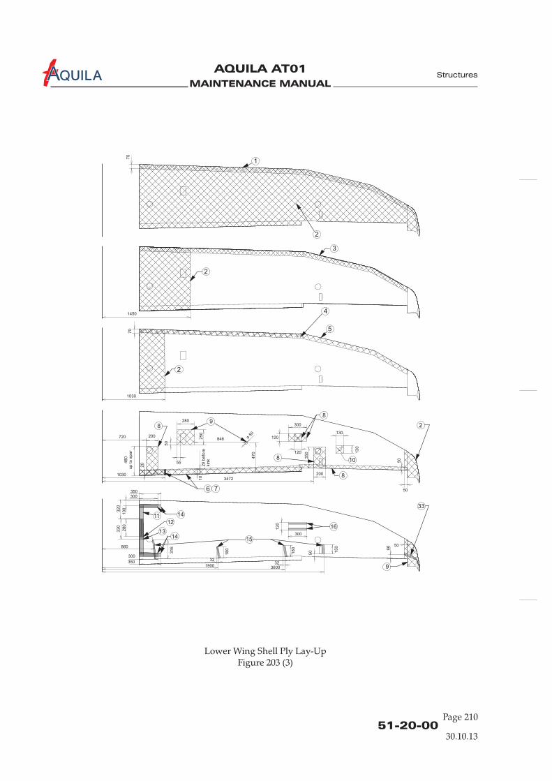
MAINTENANCE MANUAL
AQUILA AT01A
1
70
2
3
2
2
4
5
6 7
8
89
ø 50
846
8 10
1411
1413
12
350
320
316
300
100
330
280
860
300
350
1450
1030
720 200
10303472
50
70
50
55
20 b
efo
rekin
k
10
300
350
120
120
130
200
130
470
280
50
2
8
250
480
up to s
par
20
15
33
9
16
50
3232
66
150
36001900
50180
180
300
120
51-20-00Page 210
Structures
30.10.13
Lower Wing Shell Ply Lay-UpFigure 203 (3)
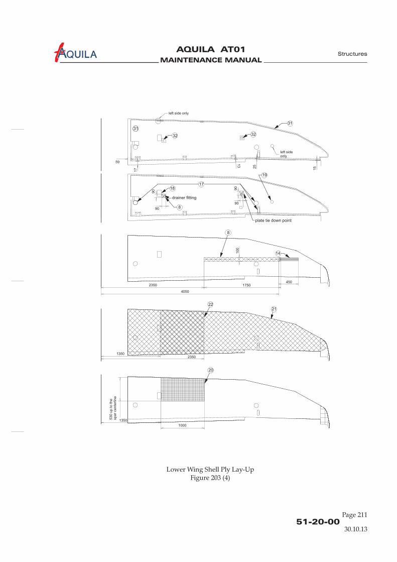
MAINTENANCE MANUAL
AQUILA AT01A
51-20-00
Page 211
Structures
30.10.13
Lower Wing Shell Ply Lay-UpFigure 203 (4)
3232
1718
drainer fitting
8
19
plate tie down point
31
left side only
left sideonly
31
59
90
90
90
90
17
13
25
15
20
1350
53
0 u
p t
o t
he
sp
ar
ce
nte
rlin
e
1000
2221
13502350
8
14
1750
4050
4502350
10
0

MAINTENANCE MANUAL
AQUILA AT01A
6.
A.
Repair of Sandwich Components
Outer Laminate Repair (surface defects)
(1) Remove surface finish from damaged area (1 inch outward).(2) Remove damaged material by sanding with 80-grit sandpaper so that the individual layers of
fabrics can be seen like plywood layers.
(3) Solvent clean prepared area.(4) Lay up repair plies according to the existing layer direction (refer to “Material Data Sheet”
above). If the layer orientation is not clear please contact AQUILA Aviation GmbH.
(5) Pre-cure the repair.(6) Sand the repair surface down to contour.(7) Refenish the repair area as described in “Exterior Finish” below.
51-20-00Page 212
Structures
30.10.13
1 inch

MAINTENANCE MANUAL
AQUILA AT01A
51-20-00
Page 213
Structures
30.10.13
B. Minor Core Damage (damaged area has a diameter of less )
(1)(2) Remove damaged laminat .(3) Solvent clean prepared area.(4) Fill the damaged foam area with filler paste and let it harden.
(5) Apply polyester filler and let it harden.
(6) Sand off any excess filler.(7) R
than 1 inch
Remove surface finish from damaged area (1 inch outward).
efinish repair area as described in “Exterior Finish” below.
e and taper laminate around core damage
0.5
inch

MAINTENANCE MANUAL
AQUILA AT01A
51-20-00Page 214
Structures
C. Minor Core Damage (damaged area has a diameter of )
(1)
more than 1 inch
Remove surface finish from damaged area (1 inch outward).(2) Remove damaged laminat .(3) Solvent clean prepared area.(4) Fill the damaged foam area with resin thickened by microballoons and let it harden.(5) Sand the repair area down to contour.
(6) Solvent clean prepared area.(7) Lay up repair plies according to the existing layer direction (refer to “Material Data Sheet”
above). If the layer orientation is not clear please contact AQUILA Aviation GmbH.Overlap min. 0.5 inch between first ply and laminate edge.
(8) Pre-cure the repair.(9) Sand the repair surface down to contour.(10) Refenish the repair area as described in “Exterior Finish” below.
e and taper laminate around core damage
30.10.13
0.5
inch
0.5
inch

MAINTENANCE MANUAL
AQUILA AT01A
51-20-00
Page 215
Structures
30.10.13
D. Core Replacement
(1) Remove surface finish from damaged area (1 inch outward).(2) Remove damaged outer laminate and core and carefully trim out to a circular or oval shape.
Check edge of damage for separation of core and inner laminate. Check inner laminate fordamage and repair first if required.
(3) T .
(4) Solvent clean prepared area.(5) Prepare a replacement core (refer to “Material Data Sheet” above) and fit it snugly in the
trimmed shape. Leave a small amount of clearance for filler paste.(6) Bond in replacement core with filler paste and let it harden.
(7) Sand the replacement core down to contour.(8) Solvent clean prepared area.(9) Lay up repair plies according to the existing layer direction (refer to “Material Data Sheet”
above). If the layer orientation is not clear please contact AQUILA Aviation GmbH.Overlap min. 0.5 inch between first ply and laminate edge.
(10) Pre-cure the repair.(11) Sand the repair surface down to contour.(12) Refenish the repair area as described in “Exterior Finish” below.
aper laminate around core damage0.5
inch
0.5
inch

MAINTENANCE MANUAL
AQUILA AT01A
51-20-00Page 216
Structures
E. Inner Laminate Repair (sandwich penetration, access to inner side)
(1) Remove surface finish from damaged area (1 inch outward).(2) Remove damaged core and laminate and carefully trim out to a circular or oval shape.
Check edge of damage for separation of core and inner laminate.(3) T .
(4) Solvent clean repair area.(5) Prepare a temporary backing plate and shim and glue it to inner laminate.(6) Prepare a replacement core (refer to “Material Data Sheet” above) and fit it snugly in the
trimmed shape. Leave a small amount of clearance for filler paste.(7) Bond in replacement core with filler paste and let it harden.
(8) Sand down the replacement core to contour.(9) Solvent clean repair area.(10) Lay up outer repair plies according to the existing layer direction (refer to “Material Data
Sheet” above). If the layer orientation is not clear please contact AQUILA Aviation GmbH.Overlap min. 0.5 inch between first ply and laminate edge.
(11) Pre-cure the repair.(12) Sand the repair surface down to contour.(13) Refenish the repair area as described in “Exterior Finish” below.(14) Complete by scarfing and laminating opposite facing in a similar manner.
aper outer laminate around core damage
30.10.13
filler paste
temporary shim
temporary backing plate
hot glue
0.5
inch

MAINTENANCE MANUAL
AQUILA AT01A
F. Inner Laminate Repair (sandwich penetration, no access to inner side)
(1) Remove surface finish from damaged area (1 inch outward).(2) Remove damaged outer laminate and core where no secure bond between core and laminate
is suspected (circular or oval shaped hole). If necessary enlarge cut out to prepare an overlapin inner laminate of at least 0.8 inch (laminate thickness to overlap length ratio approx. 1:50).
(3) Taper outer laminate around core damage.
(4) Solvent clean repair area.(5) Prepare a replacement core (refer to “Material Data Sheet” above) and fit it snugly in the
trimmed shape. Leave a small amount of clearance for filler paste.(6) Prepare the foam core for inserting in the repair:
(a) Apply a thin coat of resin to the foam core.(b) Apply a coat of thickened resin to the foam core.(c) Laminate the inner layers onto the inner surface of the foam core. Make sure that layer
orientation is correct (refer to “Material Data Sheet” above).(7) Apply a thin coat of resin to the repair area.(8) Put the foam core and inner laminate into position in the repair.
(9) Pre-cure the repair.(10) Sand down the replacement core to contour.(11) Solvent clean repair area.(12) Apply a coat of thickened resin to the foam core.(13) Apply a thin coat of resin to the scarfed edges of the repair area.(14) Lay up outer repair plies according to the existing layer direction (refer to “Material Data
Sheet” above). If the layer orientation is not clear please contact AQUILA Aviation GmbH.
51-20-00
Page 217
Structures
30.10.13
laminate
foam core
0.8 inch 0.5 inch
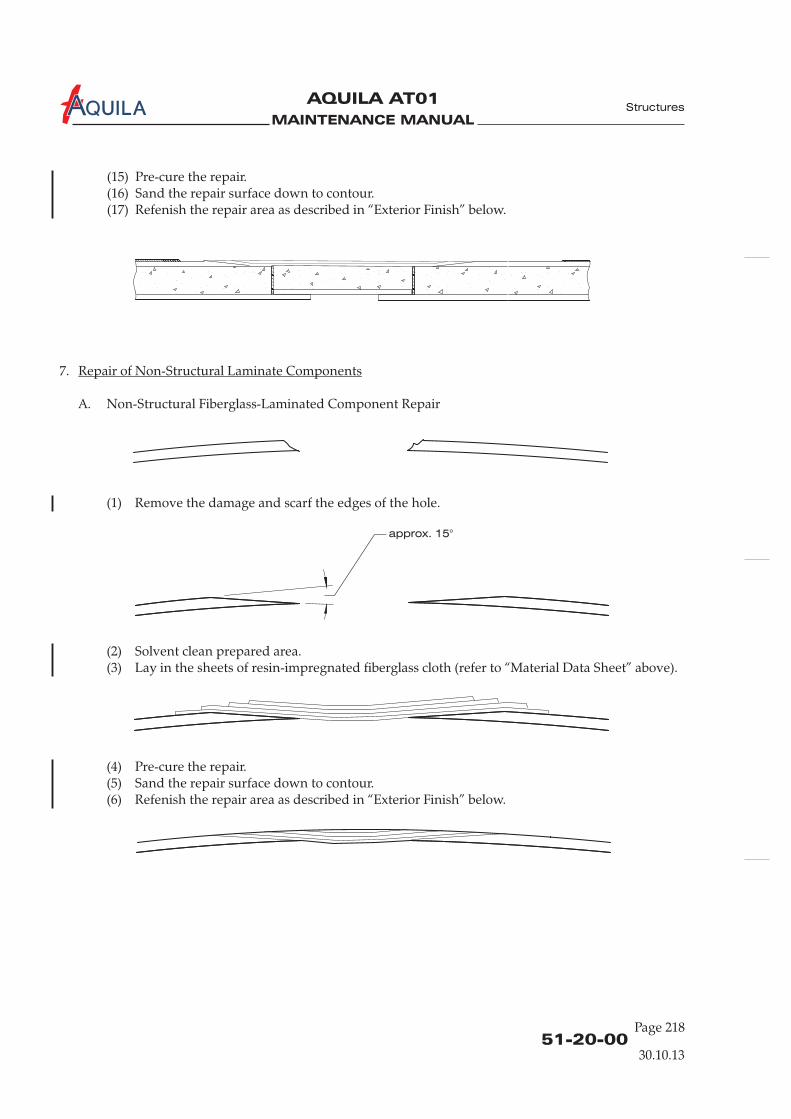
MAINTENANCE MANUAL
AQUILA AT01A
51-20-00Page 218
Structures
30.10.13
7.
A. Non-Structural Fiberglass-Laminated Component Repair
(1) Remove the damage and scarf the edges of the hole.
(2) Solvent clean prepared area.(3) Lay in the sheets of resin-impregnated fiberglass cloth (refer to “Material Data Sheet” above).
(4) Pre-cure the repair.(5) Sand the repair surface down to contour.(6) R
Repair of Non-Structural Laminate Components
efenish the repair area as described in “Exterior Finish” below.
approx. 15°
(15) Pre-cure the repair.(16) Sand the repair surface down to contour.(17) Refenish the repair area as described in “Exterior Finish” below.
MAINTENANCE MANUAL
AQUILA AT01A
51-20-00
Page 219
Structures
30.10.13
8.
Prior painting over a repair, inspect the repair to ensure that it has hardened completely and has beenproperly contoured.
MASK OFF SURFACE AROUND REPAIR AREA THAT DOES NOT REQUIRE FILLINGOR PAINT, PAY SPECIAL ATTENTION TO STATIC PORTS, ANTENNAS AND DRAINHOLES.
A. Filler
NOTE: Filler should be used for repairing cosmetic blemishes and minor surface defects.
(1) Sand the application area with 240 to 280-grit dry sandpaper.(2) Clean the application area with a suitable solvent.(3) Mix filler thoroughly in accordance with the manufacturer’s instructions.(4) Apply filler with a clean applicator according to the manufacturer’s instructions.(5) When the filler has hardened, lightly sand the repair area with 280-grit sandpaper and then
switch for final sanding to 360-grit sandpaper to remove all sanding scratches.
B. Paint(1) Prepare the surface for paint by applying filler as required.(2) Clean the application area with a suitable solvent.(3) Visually inspect prepared surface for imperfections prior to painting.(4) Mix and apply paint as recommended by the manufacturer.
Exterior Finish
CAUTION:

MAINTENANCE MANUAL
AQUILA AT01A Structures

MAINTENANCE MANUAL
AQUILA AT01A
CHAPTER 52
DOORS

MAINTENANCE MANUAL
AQUILA At01A

MAINTENANCE MANUAL
AQUILA AT01A
Page 152 - TOC
TABLE OF CONTENTS
ChapterSection
DOORS - GENERAL.........................................................................................52-00-00 1Introduction 52-00-00 1General Description 52-00-00 1
CANOPY - MAINTENANCE ..........................................................................52-10-00 201General 52-10-00 201Canopy Removal/Installation 52-10-00 201Canopy Latching Mechanism Maintenance 52-10-00 201
Title Subject Page
BAGGAGE DOOR - MAINTENANCE...........................................................52-30-00 201General 52-30-00 201Baggage Door Removal/Installation 52-30-00 201
Doors
30.10.13

MAINTENANCE MANUAL
AQUILA At01A

MAINTENANCE MANUAL
AQUILA AT01A
52-00-00
DOORS - GENERAL
1.
A. This chapter describes the canopy and the baggage door. It includes items such as structure,latching mechanism and maintenance instructions.
2.
A. The canopy consists of a composite frame and a large one-piece acrylic glass window which arebonded together. The window has two direct vision panels that can be opened in flight.The canopy moves up and forward to open. A latching mechanism holds the canopy closed bytwo latching pins. The canopy is locked from the outside with a key lock.
B. The baggage door is located on the left side of the fuselage, just aft of the wing. It is made ofcomposite materials. The door allows easy access to the baggage compartment. The baggage dooris hinged on the forward edge and latched on the rear edge. The door is locked from the outsidewith a key lock.
Introduction
General Description
Doors
30.10.13
Page 1

MAINTENANCE MANUAL
AQUILA At01A

MAINTENANCE MANUAL
AQUILA AT01A
52-10-00
Page 201
Doors
CANOPY - MAINTENANCE
1.
A. The canopy consists of a frame fabricated from carbon fiber laminate and rovings, and a large one-piece acrylic glass window which are bonded together. The window has two direct-vision panels,one on each side. The direct-vision panels can be opened in flight.The canopy is mounted to a tubular steel frame at the front. The frame attaches to two hinges onthe rear face of the firewall. The canopy moves up and forward to open. A gas strut will helpraise the canopy to the full up position and holds the canopy open.
B. The canopy latching mechanism is shown in figure 201. It incorporates two latching pins, one oneither side, and an inner and outer door handle in the left canopy frame. Rotating the doorhandle either from inside or outside the aircraft, either inserts or retracts the two latching pins intoor out of the receivers in the fuselage. The right pin operates synchronously via a push-pull cablethat runs inside the canopy frame. Roll pins hold the latch in the fully latched position.
2.
A. Remove Canopy(1) Open canopy.
(3) While helpers support the canopy, remove four hex bolts securing the canopy to the hingeframe and lift the canopy clear of the aircraft.
B. Install Canopy(1) Lift canopy into position on the aircraft.(2) Install washers and hex bolts securing the canopy to the hinge frame.
3. (Ref. Fig. 201)
A. Access Canopy Latching MechanismTo gain access to the central portion of the canopy latching mechanism, remove screws securingthe covering to canopy frame and remove covering.
THE DRIVESHAFT OF THE CANOPY LOCKING MECHANISM MAY FALLDOWN WHEN REMOVING THE ATTACHMENT SCREW.
B. Adjust Latching Pin(1) Remove screws securing the covering to the canopy and remove covering.(2) Remove the bolt, securing appropriate rod end to the actuation lever.(3) Turn the rod end in the corresponding direction.(4) Reconnect rod end to the actuation lever using bolt, washer and nut.(5) Check proper functioning of the canopy latching mechanism. Repeat the above procedures
as required.(6) Install the covering to canopy frame using screws.
General
Canopy Removal/Installation
Canopy Latching Mechanism Maintenance
CAUTION:
(2) Remove flexible air hose from canopy frame.
(3) Install flexible air hose to canopy frame.
30.10.13

MAINTENANCE MANUAL
AQUILA At01A
52-10-00Page 202
A
B
C
ADetail-
Canopy Latching MechanismFigure 201 (1)
Doors
30.10.13

MAINTENANCE MANUAL
AQUILA AT01A
52-10-00
Page 203
Doors
30.10.13
BDetail-
CDetail-
Canopy Latching MechanismFigure 201 (2)
latching pin
receiver
inner handle
outer handle
canopy lock
push-pull road
spacer
spacer
locking pin
shaft
actuation lever
spacer
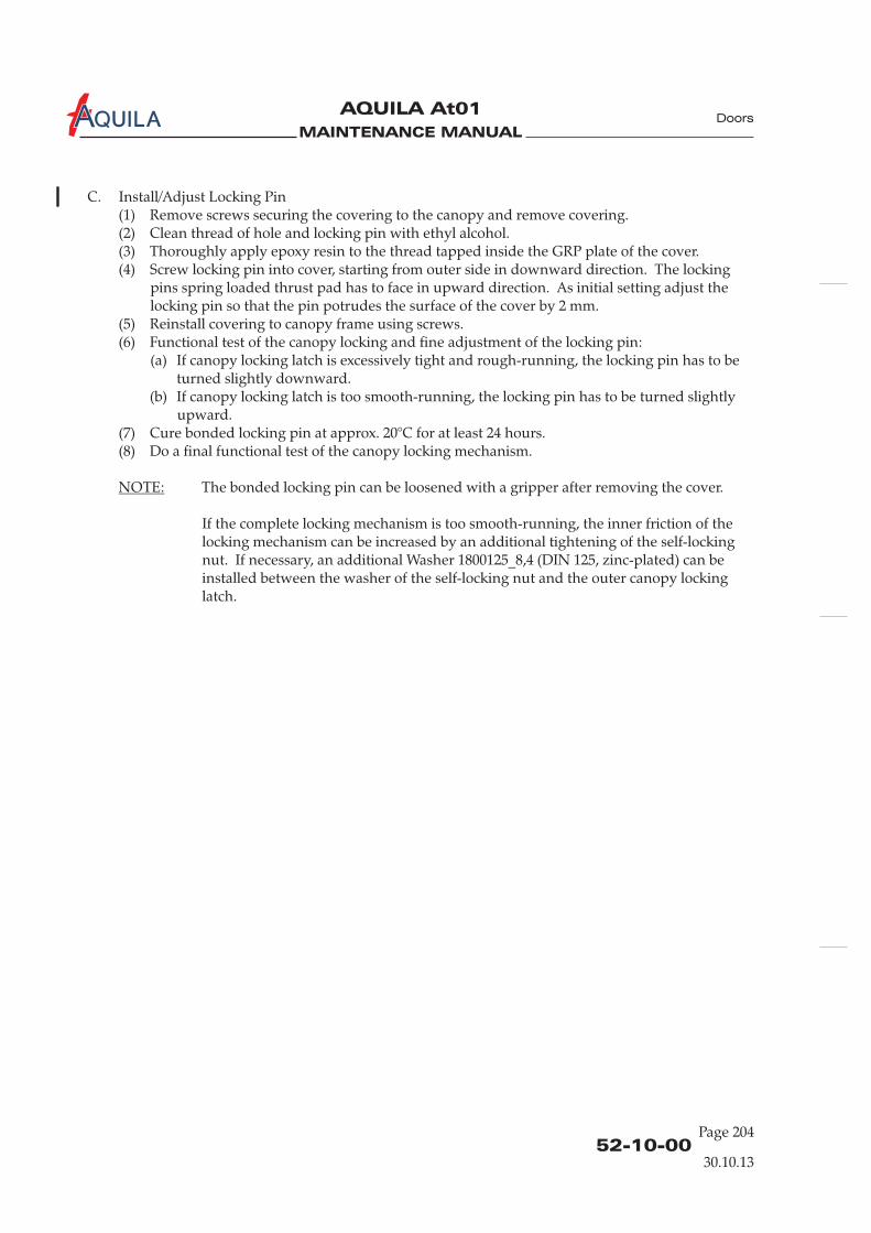
MAINTENANCE MANUAL
AQUILA At01A
52-10-00Page 204
Doors
C. Install/Adjust Locking Pin(1) Remove screws securing the covering to the canopy and remove covering.(2) Clean thread of hole and locking pin with ethyl alcohol.(3) Thoroughly apply epoxy resin to the thread tapped inside the GRP plate of the cover.(4) Screw locking pin into cover, starting from outer side in downward direction. The locking
pins spring loaded thrust pad has to face in upward direction. As initial setting adjust thelocking pin so that the pin potrudes the surface of the cover by 2 mm.
(5) Reinstall covering to canopy frame using screws.(6) Functional test of the canopy locking and fine adjustment of the locking pin:
(a) If canopy locking latch is excessively tight and rough-running, the locking pin has to beturned slightly downward.
(b) If canopy locking latch is too smooth-running, the locking pin has to be turned slightlyupward.
(7) Cure bonded locking pin at approx. 20°C for at least 24 hours.(8) Do a final functional test of the canopy locking mechanism.
NOTE: The bonded locking pin can be loosened with a gripper after removing the cover.
If the complete locking mechanism is too smooth-running, the inner friction of thelocking mechanism can be increased by an additional tightening of the self-lockingnut. If necessary, an additional Washer 1800125_8,4 (DIN 125, zinc-plated) can beinstalled between the washer of the self-locking nut and the outer canopy lockinglatch.
30.10.13
MAINTENANCE MANUAL
AQUILA AT01A
BAGGAGE DOOR - MAINTENANCE
1.
A. The baggage door is made of glass fiber laminate. It is hinged on the forward edge via two GFRPhinge arms and latched on the rear edge. The door is locked from the outside with a key lock.
2.
A. Remove Baggage Door(1) Open baggage door.(2) While supporting the baggage door, remove the cotter pins, bolts and washers securing the
baggage door hinge arms to the fuselage.(3) Remove baggage door.
B. Install Baggage Door(1) Lift baggage door into position on the aircraft.(2) Install bolts, washers and cotter pins securing the baggage door hinge arms to the fuselage.(3) Perform functional check of the baggage door latching mechanism.
General
Baggage Door Removal/Installation
52-30-00
Page 201
30.10.13
Doors

MAINTENANCE MANUAL
AQUILA At01A
MAINTENANCE MANUAL
AQUILA AT01A
CHAPTER 53
FUSELAGE

MAINTENANCE MANUAL
AQUILA AT01A

MAINTENANCE MANUAL
AQUILA AT01A
Page 1
30.10.1353 - TOC
Fuselage
TABLE OF CONTENTS
ChapterSection
FUSELAGE - GENERAL...................................................................................53-00-00 1Introduction 53-00-00 1General Description 53-00-00 1
FUSELAGE MAIN FRAME - DESCRIPTION ...............................................53-10-00 1Description and Operation 53-10-00 1
FUSELAGE MAIN FRAME - MAINTENANCE............................................53-10-00 201General 53-10-00 201
Title Subject Page
AUXILIARY STRUCTURE - DESCRIPTION.................................................53-20-00 1Description and Operation 53-20-00 1

MAINTENANCE MANUAL
AQUILA AT01A

MAINTENANCE MANUAL
AQUILA AT01A
53-00-0030.10.13
FUSELAGE - GENERAL
1.
A. This chapter provides a description of the general fuselage structure. For systems andcomponents installed in the fuselage structure, refer to the respective chapters in this manual.
2.
A. The fuselage is a semi-monocoque structure made primarily of composite materials. The fuselagestructure consists of two halves made from fiberglass laminate bonded along a centerline lap-joint.The vertical stabilizer is an integral part of the fuselage structure. Bulkheads and frames give thefuselage strength and stiffness.
The fuselage shells are primarily solid laminate (no foam) constructions. Only the area of thevertical stabilizer is made of fiberglass with a foam core. The fuselage skin is reinforced by fourcarbon-fiber stringers, arranged lengthwise through the entire fuselage.
Introduction
General Description
Fuselage
Page 1

MAINTENANCE MANUAL
AQUILA AT01A

MAINTENANCE MANUAL
AQUILA AT01A
53-10-0030.10.13
FUSELAGE MAIN FRAME - DESCRIPTION
1.
This section describes those structural components which make up the main frame including firewall,bulkheads and ring frames.
A. FirewallThe firewall separates the engine compartment from the rest of the fuselage and supports variousaircraft components on both the forward and aft sides. The firewall, constructed of a GFRP/CFRPcomposite sandwich, includes metal fittings for supporting the engine mount, and incorporatesseveral hardpoints for the support of various engine and system components. The forward sidehas a fire protection lining that consists of an especially fire-resistant ceramic fleece and a stainlesssteel sheet.
B. Side Force BulkheadA sandwich-type bulkhead bonded into the fuselage belly in front of the seat bulkhead carries theside forces. It is a rigid GFRP molding.
C. Seat BulkheadThe seat bulkhead is a rigid GFRP molding. It has layers of carbon cloth on the top and bottomfaces. The bulkhead is bonded into the fuselage belly. To four hardpoints in the bulkheadstructure are provided for the attachment of the main landing gear brackets.
D. Landing Gear BulkheadThe landing gear bulkhead has a similar structure as the seat bulkhead. It carries the landing gearloads.
E. Roll-Over BarThe landing gear bulkhead, which, together with the seat bulkhead, carries the main landing gearstruts, is complemented upwards by a compact CFRP/GFRP roll-over molding.
F. Baggage Compartment BulkheadThe baggage compartment bulkhead is a sandwich construction and made from GFRP. It formsthe rear of the baggage compartment. The bulkhead bonds to the inner fuselage shells. Thepassenger seat shoulder harness is attached to the bulkhead.
G. Ring FramesThe ring frames give the fuselage aft of the cockpit strength and stiffness. They are of rigid GFRPmolding and bonded into the fuselage shells. They have holes for the rudder control cables andprovide support for the elevator pushrod bearings.
H. Vertical Stabilizer Main SparThe vertical stabilizer main spar is a rigid GFRP molding which bonds to the fuselage shell. It alsobonds to the vertical stabilizer front and rear rib.
I. Vertical Stabilizer Rear WebThe vertical stabilizer rear web is a rigid GFRP molding, which bonds to the fuselage shell and tothe vertical stabilizer rear web. The rear web assembly contains the top rudder mounting.
Description and Operation
Fuselage
Page 1

MAINTENANCE MANUAL
AQUILA AT01A
53-10-00Page 2
30.10.13
Fuselage
Fuselage StructureFigure 201 (1)
side force bulkhead
seat bulkhead
landing gear bulkhead
firewall
carbon fiber
stringers
carbon fiber
stringers
baggage compartment
bulkhead
ring frames
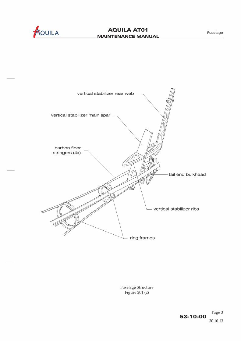
MAINTENANCE MANUAL
AQUILA AT01A
53-10-00
Page 3
Fuselage
30.10.13
Fuselage StructureFigure 201 (2)
carbon fiber
stringers (4x)
ring frames
vertical stabilizer main spar
vertical stabilizer rear web
vertical stabilizer ribs
tail end bulkhead

MAINTENANCE MANUAL
AQUILA AT01A
J. Vertical Stabilizer RibsThe vertical stabilizer front and rear ribs are of rigid GFRP molding and bonded to the fuselageshells and to the vertical stabilizer main spar. The rear rib also bonds to the rear web.
K. Tail End BulkheadThe tail end bulkhead is a rigid GFRP molding that is bonded to the fuselage shells. The bulkheadcontains a reinforced area to which the lower rudder attachment bracket is bolted.
53-10-00Page 4
30.10.13
Fuselage

MAINTENANCE MANUAL
AQUILA AT01A
FUSELAGE MAIN FRAME - MAINTENANCE
1.
A. Maintenance of the fuselage is limited to the repair of the fuselage skin. Most areas of the fuselageskin are field-repairable, some areas are difficult to repair or require special procedures to ensurethe structural integrity of the repair. Refer to chapter 51 for standard repair procedures and forrepair data for the fuselage shells.
B. If the damage area is inside the fuselage AQUILA Aviation GmbH must be contacted prior tobeginning repair work.
C. Repairs must be completed by competent technicians who are trained in composite repair.
General
53-10-00
Page 201
Fuselage
30.10.13

MAINTENANCE MANUAL
AQUILA AT01A

MAINTENANCE MANUAL
AQUILA AT01A
53-20-0030.10.13
AUXILIARY STRUCTURE - DESCRIPTION
1.
This section describes those structural components which make up the auxiliary structure includingfuselage floor structure, center console, access panels and entry step.
A.
B. Center ConsoleThe center console consists of a left, right, upper forward, lower forward and aft compositelaminate part and metal covers.
Description and Operation
Fuselage Floor StructureThe floor structure of the aircraft consists of a forward floor, a left and right baggage compartmentfloor, a left and right control stick cover and a left, right and center cover of the well of the landinggear. Forward floor and baggage compartment floors are foam core composite laminate panelsdesigned to support flight and user loads. The covers of the well of the landing gear are compositelaminate panels. Refer to 25-12-00 for an exploded view of the cabin interior.
Refer to 25-12-00 for an exploded view of the cabin interior.
C. Entry StepThe entry step is made of 28x1,5 mm [1.1x0.06 in.] steel tubes welded to a 3 mm [0.12 in.] steelflange. It is secured to the fuselage by 3 screws.
Page 1

MAINTENANCE MANUAL
AQUILA AT01A