a-5. common scm structures & materials
TRANSCRIPT
NCDEQ Stormwater Design Manual
________________________________________________________________________________________________________
A-5. Common SCM Structures & Materials 1 Revised: 2-11-2018
A-5. Common SCM Structures & Materials
Chapter Contents
• Stone and Landscape Construction Materials • Geosynthetics
• Inlet Devices
• Pretreatment Devices
• Earthen Impoundments, Embankments & Dams
• Underdrain Systems
• Outlets
Overview
There are many elements of SCM design that are common to most SCM types. Those elements are presented here rather than repeated multiple times in the individual SCM design sections. In addition, the discussion of the design elements covered in this section is not intended to be exhaustive, nor a complete design manual. Many of the subjects (aggregates, impoundments, etc.) are too complicated or site-specific to cover completely in this document, so the design professional is relied upon to make the correct design choices.
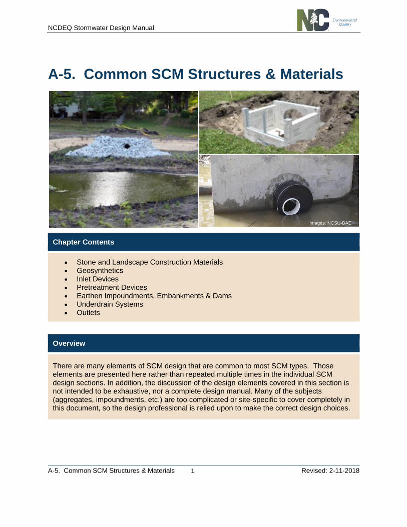
Images: NCSU-BAE
NCDEQ Stormwater Design Manual
________________________________________________________________________________________________________
A-5. Common SCM Structures & Materials 2 Revised: 2-11-2018
Stone and Landscape Construction Materials
Aggregate is natural or manufactured hard, durable, uncoated, inert particles, reasonably free from deleterious substances. Substances such as reactive chert, gypsum, iron sulfide, or amorphous silica are considered deleterious because they reduce the durability of the materials. Fine aggregates are essentially sand materials and coarse aggregates are essentially stone or gravel. Section 1005 of the NCDOT specifications (https://connect.ncdot.gov/resources/Specifications/Pages/2012StandSpecifications.aspx) provides grain sizes and durability specifications for several grades of coarse and fine aggregates. Aggregates can be used to modify soil media such as increasing permeability, or can be the sole media in a SCM, depending on the situation. Sand may be considered a fine aggregate.
Rock lining or riprap is a constructed layer or facing of stone placed to prevent erosion, scour, or sloughing of an earthen structure or embankment. The term “riprap” also is frequently defined as the stone used to construct such a lining. Riprap is a special class of very large aggregate. Riprap gradations range in diameter from 2 to 42 inches and can be of uniform size or mixed gradations depending on the application. Because riprap is typically subject to significant energy, it is important that it be sound and free from defects or entrained substances such as soil shale or organic materials. The resistance of riprap to displacement by moving water is a function of the weight, size, and shape of the stone; the geometry of the channel or bank it is protecting; the velocity of the water; the magnitude of wave energy; and the filter blanket over which the riprap is placed. Riprap is typically installed over a layer of crushed aggregate or geotextile for bedding and to prevent erosion of the underlying soils. Section 1042 of the NCDOT specifications gives the size, gradation, and durability specifications for several grades of riprap.
Gabion systems or wire-enclosed riprap consist of mats or baskets fabricated from wire mesh, filled with small riprap, and stacked or anchored to a slope. Wrapping the riprap allows smaller riprap to be used for the same resistance to displacement by water energy as larger unwrapped riprap. This is particularly advantageous when constructing rock lining in areas inaccessible to trucks or large construction equipment. The wire baskets also allow steeper (to nearly vertical) channel linings to be constructed. Gabion baskets or mattresses can be constructed from commercially available wire units or from available wire fencing material. Suppliers of prefabricated gabions generally provide extensive criteria for using their products. If prefabricated systems are used, manufacturers’ guidelines must be followed. If gabions are to be constructed on-site, the designer should reference USDOT HEC 11 (1989). The life of a gabion structure depends on the mesh material, the durability of the stone, the stability of the infill material, and the exposure conditions on site. For example, coated, galvanized steel wire resists chemical attack typical of earth retaining structures. The durability will also be affected by scour effects in streams. Specific durability information should be obtained from the manufacturer.
Landscaping blocks are typically cast of concrete and come in varying sizes, shapes, colors, and appearances. Small, decorative landscaping blocks are often used to enhance aesthetics and provide minor slope control on SCMs that might be located in high pedestrian traffic areas. Larger landscaping blocks can be used to provide significant landscape elevation differences (large soil retaining walls), or to provide a vertical or near vertical water/soil interface with erosion control, similar to what rip-rap or gabions can provide (e.g.
NCDEQ Stormwater Design Manual
________________________________________________________________________________________________________
A-5. Common SCM Structures & Materials 3 Revised: 2-11-2018
bulkheads). These larger types of applications might require extensive use of manufacturer’s recommendations and use of licensed design professionals and installers.
Geosynthetics
It is often the case that the soils located on the site will not fulfill all the necessary functions a SCM design may require. The use of geosynthetics can often supplement, enhance, or replace certain natural materials in a SCM design. Construction materials consisting of synthetic components made for use with or within earth materials generally are referred to as geosynthetics. Because these products are highly variable in both material and geometry, it is difficult to develop design guidelines applicable to all systems. The manufacturer’s project-specific design criteria should be followed and documented for each specific application. The following paragraphs discuss the four main categories of geosynthetics: Geotextiles, Geomembranes, Geonets/Geocomposites, and Geocells.
Geotextiles are the most common geosynthetics and consist of woven or non-woven fabric made from polymeric materials, such as polyester or polypropylene, or from natural fibers, such as coir (coconut hull fibers). Geotextiles utilizing natural or organic materials such as jute or coir fiber woven into mats and used for soil or turf stabilization are traditionally referred to as matting. Four main uses for geotextiles include stabilization, separation, filtration, and in-plane drainage. It should be noted, however, that geotextiles often provide many of the functions listed above at the same time, whether intended or not. Geotextiles primarily used for stabilization to protect soils and seeds from erosion are often referred to as “rolled erosion control products” and can be temporary or permanent (bio- and/or photo-degradation specifications are important). Geotextiles providing separation capabilities are placed between dissimilar materials to prevent migration of one of the materials into the other, or to discourage undesirable root growth into underlying drain systems. Geotextiles providing filtration would typically prevent the movement of fine particles from soil through which seepage occurs. And finally, certain types of geotextiles, in particular thick-needle punched non- woven geotextiles, have sufficient in-plane flow capacity for use as flow conduits in certain applications.
Geomembranes are continuous polymeric sheets that are, for all practical purposes, impermeable. There are many varieties of geomembranes in use today; however, the most frequently used geomembranes for ground applications are thermoplastic products manufactured from high-density polyethylene (HDPE) and polyvinyl chloride (PVC). Different types of geomembranes have significantly different properties, including strength, longevity, resistance to ultraviolet light, thermal expansion and contraction, chemical resistance, and ease of installation. The most appropriate geomembrane to use for a given application is dependent on the application and the environment to which the geomembrane will be exposed.
Geocomposites consist of a combination of geosynthetic components. Geocomposites used in SCM applications are usually sheet- or edge-drains consisting of a prefabricated core to which a geotextile filter is bonded. The core provides void space through which water can flow in-plane while the geotextile filter keeps soil from filling the voids created by the core. Geocomposite sheet drains are available that allow flow in from one or both faces. Geonets are a type of geosynthetic that consists of a continuous extrusion of polymeric ribs. The ribs themselves form void space through which in-plane flow capacity is provided. Geonets are available with or
NCDEQ Stormwater Design Manual
________________________________________________________________________________________________________
A-5. Common SCM Structures & Materials 4 Revised: 2-11-2018
without bonded geotextile filters. Geonets with bonded geotextile filters are sometimes referred to as composite drainage nets (CDNs).
Geocells are three-dimensional prefabricated polymeric systems ranging from 4 to 8 inches high. The geocell systems are collapsed for delivery to the site. Upon arrival at a site, they are spread open and filled to form a three-dimensional reinforced mattress. Originally developed to rapidly stabilize soft subgrades for mobilization of large equipment, they are now frequently used for protection and stabilization of steep slope surfaces and protective linings for channels. Because use of geocells for slope stabilization applications is relatively new, there is little available design guidance beyond that available from the manufacturers.
Inlet Devices
In order for SCM’s to function properly, a specified quantity of stormwater runoff must be conveyed to the measure in a controlled manner. Traditional methods for accomplishing this include drainage inlets, yard inlets, curb inlets and other types of inlets connected to a conveyance system consisting of closed pipes and open channels. However, there are some specific devices associated with SCM’s that warrant further discussion.
Curb Diversion Devices
Curb diversion devices or curb cuts can be used to divert flow from curb-and-gutter type impervious surfaces such as roads and parking lots to a variety of SCMs (e.g. grassed swales, filter strips, restored riparian buffer, bioretention, sand filter, etc.). The use of a curb diversion device can avoid the installation of a piped stormwater collection system, however, it does not guarantee sheet flow or proper flow quantity diversion.
Curb diversions or curb cuts typically include a gap of some width in a curb section accompanied by a concrete flume, river rock pad, or some other device to prevent erosion and direct the water to the SCM or other desired location. Curb diversions may or may not incorporate a pretreatment device depending on whether they discharge to a filter strip, grassed channel, or directly to an SCM.
Flow Splitters
SCMs can either be placed on-line or off-line. An on-line SCM will receive all stormwater flows regardless of the intensity, with the flows beyond the design volume typically passing over an overflow of some type. An off-line SCM is one that typically has a flow splitter of some sort prior to the SCM, which will divert the design volume flows to the SCM and bypass a certain volume of excess flows around the SCM. For most SCMs it is advantageous to install a flow splitter prior to the SCM to bypass stormwater in excess of the design volume around the SCM. This will help minimize resuspension of sediment, hydraulic overload, and/or excessive erosion of the SCM.
Flow splitters must be designed to send all of the flow from every rainfall event into the SCM until the SCM design volume (based on the specific stormwater program requirements) has been reached, at which point the flow splitter may start diverting a portion or all of the
NCDEQ Stormwater Design Manual
________________________________________________________________________________________________________
A-5. Common SCM Structures & Materials 5 Revised: 2-11-2018
additional flow around the SCM. The diverted flow may be routed to an additional SCM (if necessary as part of the overall stormwater plan for the site), or it may be discharged to the receiving waters.
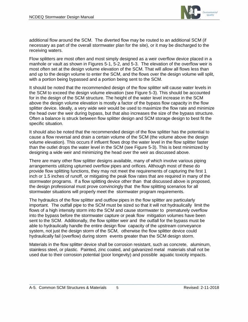
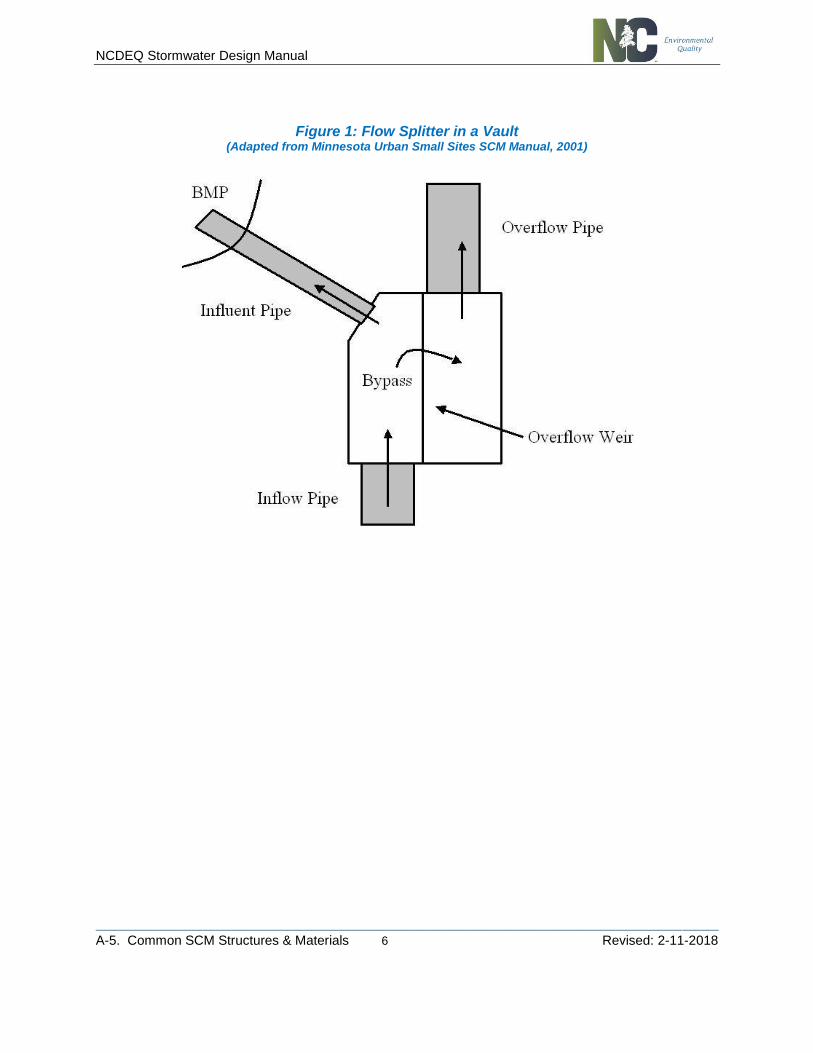
Flow splitters are most often and most simply designed as a weir overflow device placed in a manhole or vault as shown in Figures 5-1, 5-2, and 5-3. The elevation of the overflow weir is most often set at the design volume elevation of the SCM. That will allow all flows less than and up to the design volume to enter the SCM, and the flows over the design volume will split, with a portion being bypassed and a portion being sent to the SCM.
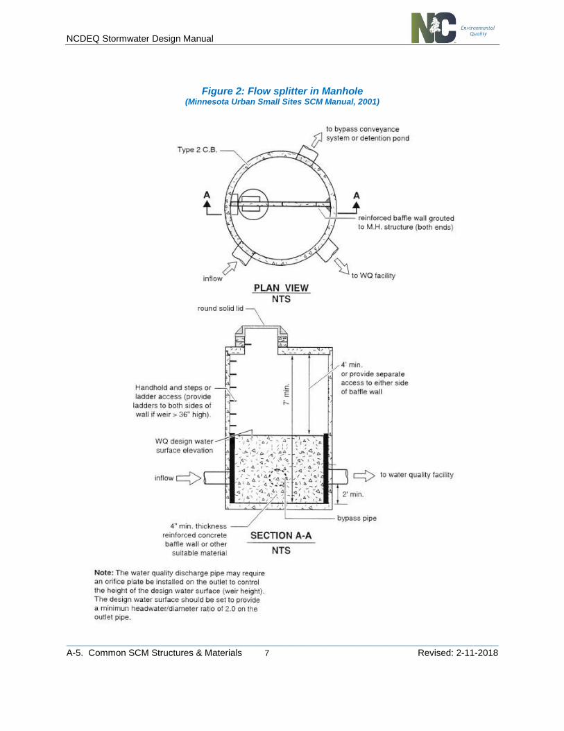
It should be noted that the recommended design of the flow splitter will cause water levels in the SCM to exceed the design volume elevation (see Figure 5-3). This should be accounted for in the design of the SCM structure. The height of the water level increase in the SCM above the design volume elevation is mostly a factor of the bypass flow capacity in the flow splitter device. Ideally, a very wide weir would be used to maximize the flow rate and minimize the head over the weir during bypass, but that also increases the size of the bypass structure. Often a balance is struck between flow splitter design and SCM storage design to best fit the specific situation.
It should also be noted that the recommended design of the flow splitter has the potential to cause a flow reversal and drain a certain volume of the SCM (the volume above the design volume elevation). This occurs if influent flows drop the water level in the flow splitter faster than the outlet drops the water level in the SCM (see Figure 5-3). This is best minimized by designing a wide weir and minimizing the head over the weir as discussed above.
There are many other flow splitter designs available, many of which involve various piping arrangements utilizing upturned overflow pipes and orifices. Although most of these do provide flow splitting functions, they may not meet the requirements of capturing the first 1 inch or 1.5 inches of runoff, or mitigating the peak flow rates that are required in many of the stormwater programs. If a flow splitting device other than that discussed above is proposed, the design professional must prove convincingly that the flow splitting scenarios for all stormwater situations will properly meet the stormwater program requirements.
The hydraulics of the flow splitter and outflow pipes in the flow splitter are particularly important. The outfall pipe to the SCM must be sized so that it will not hydraulically limit the flows of a high intensity storm into the SCM and cause stormwater to prematurely overflow into the bypass before the stormwater capture or peak flow mitigation volumes have been sent to the SCM. Additionally, the flow splitter weir and the outfall for the bypass must be able to hydraulically handle the entire design flow capacity of the upstream conveyance system, not just the design storm of the SCM, otherwise the flow splitter device could hydraulically fail (overflow) during storm events greater than the SCM design storm.
Materials in the flow splitter device shall be corrosion resistant, such as concrete, aluminum, stainless steel, or plastic. Painted, zinc coated, and galvanized metal materials shall not be used due to their corrosion potential (poor longevity) and possible aquatic toxicity impacts.
NCDEQ Stormwater Design Manual
________________________________________________________________________________________________________
A-5. Common SCM Structures & Materials 6 Revised: 2-11-2018
Figure 1: Flow Splitter in a Vault (Adapted from Minnesota Urban Small Sites SCM Manual, 2001)
NCDEQ Stormwater Design Manual
________________________________________________________________________________________________________
A-5. Common SCM Structures & Materials 7 Revised: 2-11-2018
Figure 2: Flow splitter in Manhole (Minnesota Urban Small Sites SCM Manual, 2001)
NCDEQ Stormwater Design Manual
________________________________________________________________________________________________________
A-5. Common SCM Structures & Materials 8 Revised: 2-11-2018
Figure 3: Water Level Progression in SCM with Flow Splitter (Minnesota Urban Small Sites SCM Manual, 2001)
NCDEQ Stormwater Design Manual
________________________________________________________________________________________________________
A-5. Common SCM Structures & Materials 9 Revised: 2-11-2018
Pretreatment Devices
Pretreatment devices are often included upgradiant of SCM’s to remove gross pollutants such as trash and sediments in order to preserve the functions of the SCM. They may take the form of structural devices such as forebays, sumps in catch basins, or proprietary settling devices or a more natural forms such as vegetated filter strips.
Vegetated Filter Strips
Vegetated Filter Strips (VFS) consist of a relatively flat vegetated area that remove sediment, trash, and other gross pollutants through filtration as the water passes through and is slowed by the vegetation. The VFS should be of limited slope and sufficient width to provide the desired level of pre-treatment without eroding. Slopes should generally not exceed 8% and width should be at least 5 feet. VFSs should be planted in deep rooting non-clumping turf grasses following proper preparation of the soil to ensure vigorous growth.
Catch Basin Sumps
Sumps consist of areas in catch basins and other structures below the level of designed outflow where sediment and other gross pollutants may be captured and accumulate. The accumulated pollutants must be periodically removed to ensure the continued function of the device. Catch basins may also incorporate inverted elbows, trash screens, or other outlet controls to capture floating trash and debris. Unless underdrains or other devices are incorporated to drain water between storm events, these devices will retain stagnant water and may provide ideal habitat for mosquitos.
Vortex & Other Proprietary Devices
There are a variety of proprietary devices that utilize vortex and other systems to capture and retain sediment, trash, oil, and other pollutants from stormwater. These often serve as pre-treatment devices but may be used as primary SCMs as well. Designers should consider the flow capacity, pollutant removal capabilities, and local acceptance in the selection of proprietary devices.
Forebays
A forebay is a settling basin near an inlet of a SCM to dissipate the energy of the incoming stormwater and to settle out the larger incoming sediment particles. With heavy, coarse sediment confined to the forebay area, maintenance is made simpler and less costly and the life of the SCM is extended. A forebay is required for particular SCMs and is optional for others; however, in no case does the use of a forebay provide additional credits towards pollutant removal rates.
One of the main benefits of the forebay is to collect a majority of the volume of sediment in a small area that is specifically designed for easy sediment removal. Sediment removal frequency from the SCM will likely be every 3-5 years for SCMs without forebays, as opposed to every 15-25 years for some SCMs with forebays. Due to the ease of removal of sediment from the forebay, the overall cost should be less over the same period by installing a forebay. In addition, having a forebay with more frequent cleanout makes it is easier for sediment

NCDEQ Stormwater Design Manual
________________________________________________________________________________________________________
A-5. Common SCM Structures & Materials 10 Revised: 2-11-2018
removal to be more of an ongoing operation and maintenance cost that is properly funded rather than a surprise capital expense that was not accounted for.
Sediment forebays shall have direct access provided for appropriate maintenance equipment. The designer of the SCM should consider if a hardened surface (gravel, open concrete pavers, etc.) should be incorporated into the aesthetic design for the access point and a staging pad next to the forebay. This would reduce erosion and vegetation disturbance during sediment removal operations. In addition, the bottom of the forebay should be made of hardened material, if compatible with the design. A forebay that will be permanently submerged could have a solid concrete bottom, and one that is exposed could have open concrete pavers that allow grasses or other small vegetation to grow in the openings.
A fixed vertical sediment depth marker should be installed in the forebay to measure sediment deposition over time. In general, sediment shall be removed when the designed sediment storage depth of the forebay is filled in with sediment. Refer to the specific SCM design chapters for minimum requirements for the designed sediment storage depth.
Some sort of separation structure must be provided to separate the forebay from the main body of the SCM. That structure can be an earthen or rip-rap berm, or a wall made of concrete or a gabion system. The forebay could be set at a higher elevation than the main SCM and the separation structure could therefore be set several feet above the design storm water level of the SCM and operate as an overflow structure to the SCM. The elevation of the separation structure can also be as low as (but not to exceed) 1 foot below the design storm water elevation. Regardless of the relative elevation of the separation structure, the water flowing over (and possibly through) it must be at a non- erosive velocity, preferably by designing the entire overflow structure at a single elevation to act as one large weir.
Use of a vegetated shelf is recommended, especially if a vegetated shelf is utilized in the main SCM structure. This shelf will not only increase safety, but it also benefits water quality, and discourages non-migratory Canada geese from establishing.
If the SCM has a volume of permanent water that is required as part of the design for proper treatment, any permanent volume of water within the forebay can be included as part of the overall treatment volume required. If the SCM is required to have storage volume for capturing stormwater during a storm event, any dry storage volume within the forebay that will fill and empty with the storm similar to the main body of the SCM, may be included in the overall storage volume to meet the requirements.
Forebay volume shall be approximately 20% of the total required storage volume (unless noted otherwise in a specific SCM design section). This leaves about 80% of the design volume in the main basin. Multiple inlets may require additional forebay volume (or additional forebays). A forebay should be designed so that it has two zones. The first zone, where the water enters the forebay, should be approximately three feet deep. This zone will dissipate hydraulic energy entering the forebay. The second zone, near the berm where the water will spill into the main pond, should be approximately one foot deep. This zone will accommodate settling. The depth of the bottom of the forebay should taper between these two depths.
NCDEQ Stormwater Design Manual
________________________________________________________________________________________________________
A-5. Common SCM Structures & Materials 11 Revised: 2-11-2018
Earthen Impoundments, Embankments & Dams
Many SCMs will involve construction of some volume of water storage for water treatment and/or water quantity control. The most common type of storage facility is the earthen impoundment. These structures sometimes are simply dug out of existing soil and are below grade, but others involve fill material and dams.
This document only discusses some general considerations when utilizing earthen impoundments in SCMs and does not cover earthen embankment or dam design. A licensed design professional should make sure any impoundments, embankments and/or dams designed as part of a SCM meet any applicable requirements of the dam safety regulations found in 15A 2K Section .0100 through .0500. These rules include detailed information on dam classification (i.e., low, medium and high hazard dams), design information, and review and approval requirements. Water detention basins that meet one or more of the following criteria may be regulated as dams by DEQ:
• Have a high hazard potential, or
• Embankments higher than 15 feet, measured from the highest point on the top
of the dam to the lowest point on the downstream toe; and
• Impounded volumes more than 10 acre-feet of runoff to the top of the dam.
Many factors must be taken into consideration when designing an earthen impoundment utilizing embankments and/or dams, including: foundation preparation and treatment, control of seepage, embankment stability, subsidence/settlement, piping, and maintenance. The following points include some specific information to incorporate in the design of impoundments utilizing embankments and/or dams:
• A maximum slope of 3H:1V shall be used on the embankments to allow maintenance equipment and to maintain ground cover. If site conditions require steeper slopes on one side of the basin, slope stability techniques should be used to ensure long-term stability of the slope.
• The height of an embankment dam must consider freeboard and compensation for settlement. The basin’s freeboard should be a minimum of 1 foot above the elevation of the highest stage calculated based on the 100-year storm.
• Pipes and other conduits through the embankment should be avoided if at all possible. If a penetration is necessary through the embankment (typically for the outlet device) then seepage should be minimized through the use of anti- seep collars or filter and drainage diaphragms.
• A grass surface is preferred unless frequent vehicle traffic or foot travel is expected, in which case gravel, modular paving block, or similar surface should be installed to prevent erosion and rutting. If vegetation is used to stabilize the embankment, proper maintenance, including mowing, fertilizing, and reseeding bare-spots, is required to prevent erosion. Other maintenance items are discussed in Chapter A-6, Operation & Maintenance, as well as in individual SCM design sections.
• Embankment dams should be nonlinear where possible for aesthetic reasons. Concave embankments are inherently more stable than convex alignments.
NCDEQ Stormwater Design Manual
________________________________________________________________________________________________________
A-5. Common SCM Structures & Materials 12 Revised: 2-11-2018
• When an impoundment is located in karst topography, gravelly sands, or fractured bedrock, a liner may be needed to sustain a permanent pool of water. If geotechnical tests confirm the need for a liner, acceptable options can include: 6 to 12 inches of clay soil (minimum 15 percent passing the #200 sieve and a maximum permeability of 1 x 10 -5 cm/sec), a 30 mil poly-liner, or a bentonite liner.
Underdrain Systems
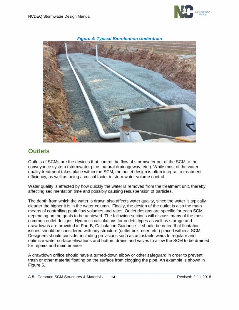
Underdrain systems are utilized in several SCM designs, and can have many different configurations. The underdrain system will either daylight, connect to another SCM, or connect to the conveyance system. All piping within the underdrain system should have a minimum slope of 0.5 percent and should be constructed of Schedule 40 or SDR 35 smooth wall PVC pipe. The underdrain pipes should be designed to carry 2-10 times the maximum flow exfiltrating from the SCM medium. Choose a value within this range to reflect the expected stability of the drainage area. This maximum flow is computed from Darcy's law and assuming maximum ponding and complete saturation along the depth of the medium. Manning's formula is then used to size the pipe. Due to the risk of underdrain clogging, designers are encouraged to install more than one underdrain of smaller diameter in order to facilitate drainage. The minimum size of pipe should be 4-inch diameter. The spacing of collection laterals should be no greater than 10 feet center to center, and a minimum of two pipes should be installed to allow for redundancy (Hunt and White, 2001). A minimum of 4 rows of perforations should be provided around the diameter of the pipe (more for pipes 10 inches in diameter and larger), and the perforations should be placed 6 inches on center within each row for the entire length of the drainage lateral. Perforations should be 3/8-inch in diameter.
The underdrain pipes should have a minimum of 3 inches of washed #57 stone above and on each side of the pipe (stone is not required below the pipe). Above the stone, either filter fabric or two inches of choking stone is recommended to protect the underdrain from blockage. Avoid filter fabric if there is any question about the future stability of the drainage area. Above the filtering device, a minimum of 2 inches of washed sand should be installed. Choking stone (#8 or #89) in lieu of filter fabric is recommended if there is potential for higher sediment loads that would lead to clogging. Pipe socks are also not recommended.
Typically, bioretention SCMs in the Piedmont region of North Carolina will require underdrains with an up-turned elbow.
The number of pipes needed for the underdrain system can be determined using the following 3-step process:
1. Determine flow rate through the soil media and apply a safety factor of 10 (this is now the underdrain design flow, Q).
2. Use Equation 1 below:

NCDEQ Stormwater Design Manual
________________________________________________________________________________________________________
A-5. Common SCM Structures & Materials 13 Revised: 2-11-2018
Equation 1: Underdrain Pipe Size
8
3
5.0
*16
S
nQD
where: D = Diameter of single pipe (inches) n = Roughness factor (recommended to be 0.011) S = Internal slope (recommended to be 0.5%) Q = Underdrain design flow (cfs)
3. The only unknown is D. This is the diameter of a single pipe that could carry all the water were it to be the only underdrain. Underdrain pipe diameters are typically either 4 inches or 6 inches. Table 1 and 2 below convert D (in inches) to an equal number of 4 or 6 inch underdrains at 0.5% slope.
Table 1: Number of 4” Pipes Required in the Underdrain
If D is Less Than No. of 4” Pipes
5.13 2
5.95 3
6.66 4
7.22 5
7.75 6
8.20 7
Table 2: Number of 6” Pipes Required in the Underdrain
If D is Less Than No. of 6” Pipes
7.84 2
9.11 3
10.13 4
NCDEQ Stormwater Design Manual
________________________________________________________________________________________________________
A-5. Common SCM Structures & Materials 14 Revised: 2-11-2018
Figure 4: Typical Bioretention Underdrain
Outlets
Outlets of SCMs are the devices that control the flow of stormwater out of the SCM to the conveyance system (stormwater pipe, natural drainageway, etc.). While most of the water quality treatment takes place within the SCM, the outlet design is often integral to treatment efficiency, as well as being a critical factor in stormwater volume control.
Water quality is affected by how quickly the water is removed from the treatment unit, thereby affecting sedimentation time and possibly causing resuspension of particles.
The depth from which the water is drawn also affects water quality, since the water is typically cleaner the higher it is in the water column. Finally, the design of the outlet is also the main means of controlling peak flow volumes and rates. Outlet designs are specific for each SCM depending on the goals to be achieved. The following sections will discuss many of the most common outlet designs. Hydraulic calculations for outlets types as well as storage and drawdowns are provided in Part B, Calculation Guidance. It should be noted that floatation issues should be considered with any structure (outlet box, riser, etc.) placed within a SCM. Designers should consider including provisions such as adjustable weirs to regulate and optimize water surface elevations and bottom drains and valves to allow the SCM to be drained for repairs and maintenance
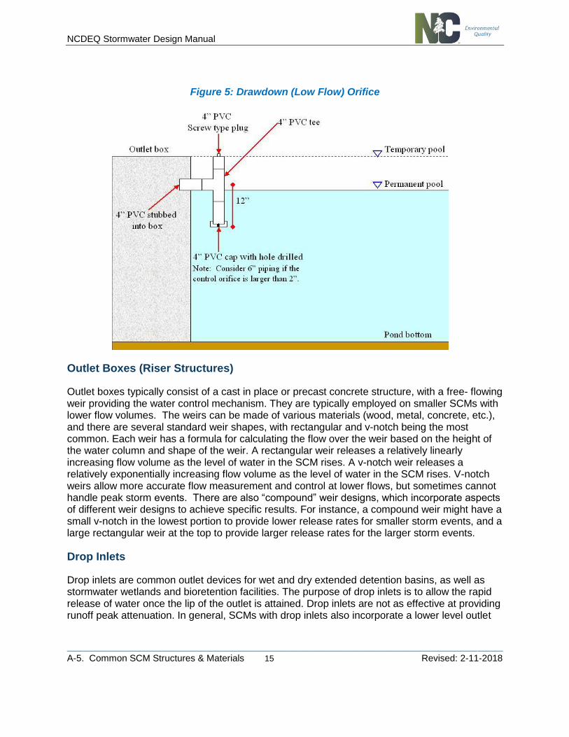
A drawdown orifice should have a turned-down elbow or other safeguard in order to prevent trash or other material floating on the surface from clogging the pipe. An example is shown in Figure 5.
NCDEQ Stormwater Design Manual
________________________________________________________________________________________________________
A-5. Common SCM Structures & Materials 15 Revised: 2-11-2018
Figure 5: Drawdown (Low Flow) Orifice
Outlet Boxes (Riser Structures)
Outlet boxes typically consist of a cast in place or precast concrete structure, with a free- flowing weir providing the water control mechanism. They are typically employed on smaller SCMs with lower flow volumes. The weirs can be made of various materials (wood, metal, concrete, etc.), and there are several standard weir shapes, with rectangular and v-notch being the most common. Each weir has a formula for calculating the flow over the weir based on the height of the water column and shape of the weir. A rectangular weir releases a relatively linearly increasing flow volume as the level of water in the SCM rises. A v-notch weir releases a relatively exponentially increasing flow volume as the level of water in the SCM rises. V-notch weirs allow more accurate flow measurement and control at lower flows, but sometimes cannot handle peak storm events. There are also “compound” weir designs, which incorporate aspects of different weir designs to achieve specific results. For instance, a compound weir might have a small v-notch in the lowest portion to provide lower release rates for smaller storm events, and a large rectangular weir at the top to provide larger release rates for the larger storm events.
Drop Inlets
Drop inlets are common outlet devices for wet and dry extended detention basins, as well as stormwater wetlands and bioretention facilities. The purpose of drop inlets is to allow the rapid release of water once the lip of the outlet is attained. Drop inlets are not as effective at providing runoff peak attenuation. In general, SCMs with drop inlets also incorporate a lower level outlet
NCDEQ Stormwater Design Manual
________________________________________________________________________________________________________
A-5. Common SCM Structures & Materials 16 Revised: 2-11-2018
or an outlet designed to achieve specific attenuation objectives (see Multiple Outlets section below).
Drop inlets usually consist of a riser structure in the reservoir area connected to a pipe or box culvert (outlet conduit) that extends through the dam embankment. Drop inlets should be designed to operate as weirs. To maintain weir type conditions, the head over the inlet should not exceed 33% of the inlet riser diameter. At greater heads, the flow may become unstable as it approaches the transition to orifice flow, leading to surging, noise, vibration, or vortex action. In addition, downstream conditions, full flow conditions in the pipe, or other factors can result in complicated hydraulics that may cause excessive surging, noise, or vibration during operation. A full hydraulic analysis of the entire drop inlet system showing the controlling factors at all flow regimes is recommended to ensure proper operation.
Perforated Risers
Another common outlet type for relatively small SCMs is a vertical riser with one or more columns of perforations. It is typically constructed out of plastic pipe (PVC, HDPE, etc.). The objective of providing an array of small orifices, instead of a single orifice, is to reduce the velocity of currents near the outlet. Perforations larger than 1-inch diameter are not recommended.
Perforated risers have the disadvantage that the outlet rates are greatest early in a storm event when most of the entrained sediment is still suspended. Perforated risers also draw most of the discharged water from the deepest portions of the basins where the highest concentration of suspended sediments occur.
Multiple Outlets
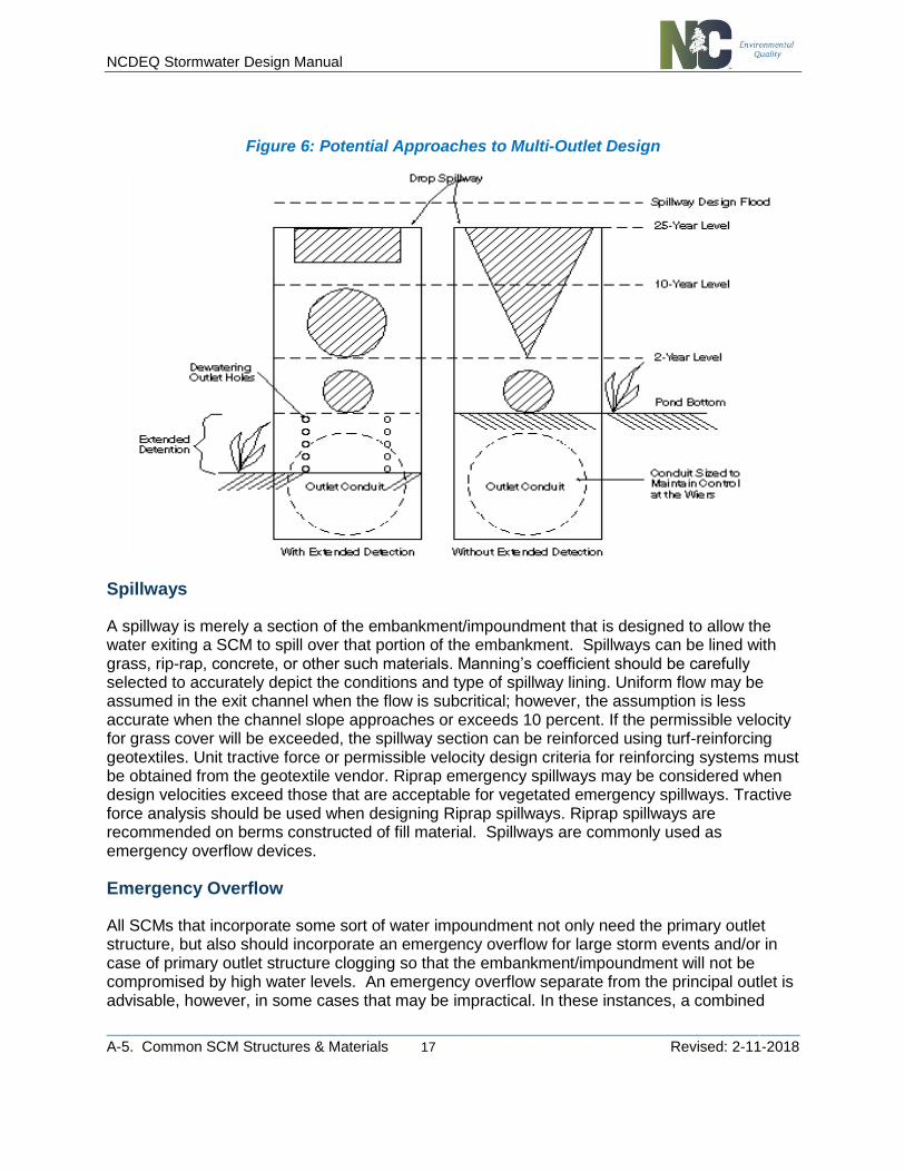
Multiple outlets are used to achieve specific runoff peak attenuation goals. In general, runoff peak control is required for several storm magnitudes. Outlets are arranged to provide the required attenuation while minimizing the overall size of the basin. Multiple outlets frequently combine a number of different control devices, including orifices, rectangular and V-notch weirs, and drop inlets (see Figure 6). Flow curves for the various outlets at different water elevations are simply superimposed to provide the overall discharge rate.
NCDEQ Stormwater Design Manual
________________________________________________________________________________________________________
A-5. Common SCM Structures & Materials 17 Revised: 2-11-2018
Figure 6: Potential Approaches to Multi-Outlet Design
Spillways
A spillway is merely a section of the embankment/impoundment that is designed to allow the water exiting a SCM to spill over that portion of the embankment. Spillways can be lined with grass, rip-rap, concrete, or other such materials. Manning’s coefficient should be carefully selected to accurately depict the conditions and type of spillway lining. Uniform flow may be assumed in the exit channel when the flow is subcritical; however, the assumption is less accurate when the channel slope approaches or exceeds 10 percent. If the permissible velocity for grass cover will be exceeded, the spillway section can be reinforced using turf-reinforcing geotextiles. Unit tractive force or permissible velocity design criteria for reinforcing systems must be obtained from the geotextile vendor. Riprap emergency spillways may be considered when design velocities exceed those that are acceptable for vegetated emergency spillways. Tractive force analysis should be used when designing Riprap spillways. Riprap spillways are recommended on berms constructed of fill material. Spillways are commonly used as emergency overflow devices.
Emergency Overflow
All SCMs that incorporate some sort of water impoundment not only need the primary outlet structure, but also should incorporate an emergency overflow for large storm events and/or in case of primary outlet structure clogging so that the embankment/impoundment will not be compromised by high water levels. An emergency overflow separate from the principal outlet is advisable, however, in some cases that may be impractical. In these instances, a combined
NCDEQ Stormwater Design Manual
________________________________________________________________________________________________________
A-5. Common SCM Structures & Materials 18 Revised: 2-11-2018
principal-emergency outlet may be considered. A combined principal-emergency outlet is a single outlet structure that conveys both low flows (e.g., stormwater management functions) and extreme flows. A primary design consideration for a combined principal-emergency outlet, particularly when in the form of drop inlet structures, is protection against clogging.
Trash racks should be designed as described below. When a combined principal- emergency outlet is proposed, then the emergency outlet portion should be designed as if no additional storage is available and as if all normally operating weirs, ports and/or orifices are inoperative or clogged.
Trash Racks
Most outlets are subject to some degree of trash and debris from incoming flows, and certain outlets are more susceptible to clogging than others. Before a debris control structure is designed, the anticipated debris problem should be analyzed. The type and quantity of debris are determined primarily by upstream land use, soil erodibility, watershed size, and the type of stormwater management facility.
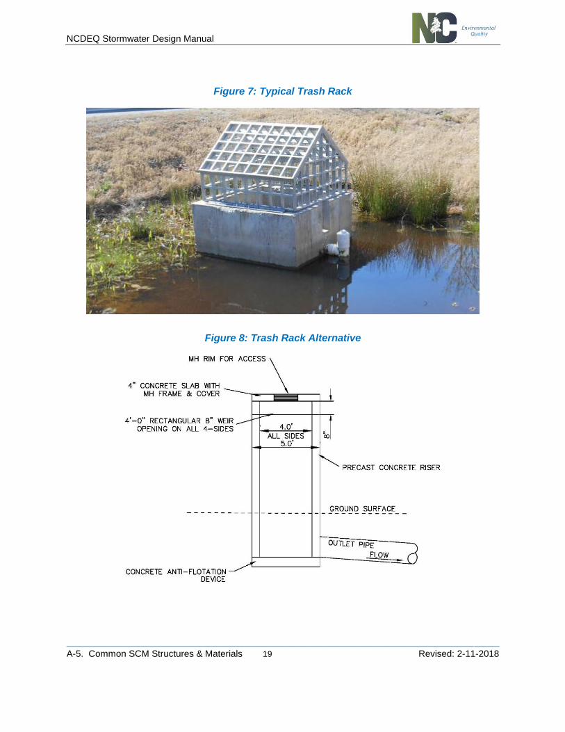
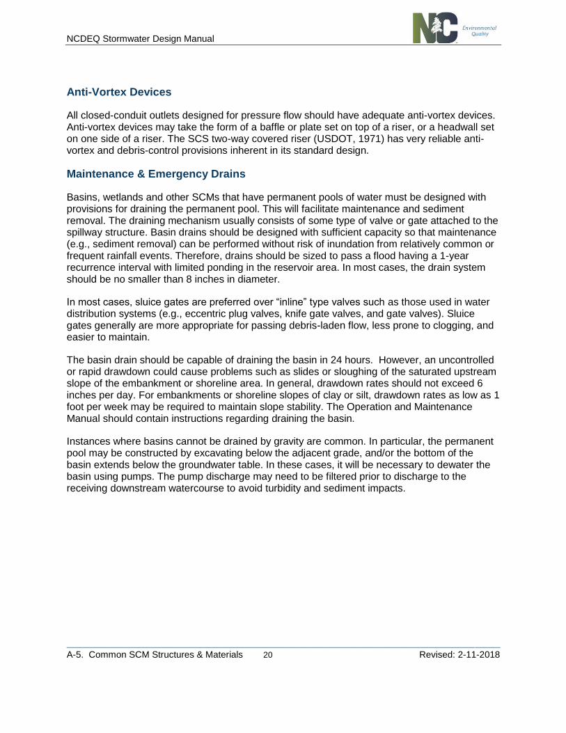
Trash racks to serve drop inlets should be designed to provide positive protection against clogging of the outlet under any operating level. The average velocity of flow through a clean trash rack should not exceed 2.5 fps during peak design flow. Velocity can be computed on the basis of the net area of opening through that part of the rack receiving the flow. The same criteria should apply to ports or openings along the side of a riser structure. The clear distance between bars generally should not be less than 2 inches; however, one exception to this may be near the apex of the trash rack. Bar spacing should be no greater than one-half of the minimum conduit dimension in the drop inlet, with an absolute maximum of 5.5 inches to discourage child access. An alternative to a typical peaked trash rack for the top of risers includes having a weir opening with a concrete slab and manhole for access (see Fig. 8 below).
In some cases, debris-control devices may be required for low-level intakes at the basin bottom. In these situations, debris control structures such as those discussed in the FHWA publication “Debris Control Structures” (HEC 9) (USDOT, 1971) should be considered where appropriate.
NCDEQ Stormwater Design Manual
________________________________________________________________________________________________________
A-5. Common SCM Structures & Materials 19 Revised: 2-11-2018
Figure 7: Typical Trash Rack
Figure 8: Trash Rack Alternative
NCDEQ Stormwater Design Manual
________________________________________________________________________________________________________
A-5. Common SCM Structures & Materials 20 Revised: 2-11-2018
Anti-Vortex Devices
All closed-conduit outlets designed for pressure flow should have adequate anti-vortex devices. Anti-vortex devices may take the form of a baffle or plate set on top of a riser, or a headwall set on one side of a riser. The SCS two-way covered riser (USDOT, 1971) has very reliable anti-vortex and debris-control provisions inherent in its standard design.
Maintenance & Emergency Drains
Basins, wetlands and other SCMs that have permanent pools of water must be designed with provisions for draining the permanent pool. This will facilitate maintenance and sediment removal. The draining mechanism usually consists of some type of valve or gate attached to the spillway structure. Basin drains should be designed with sufficient capacity so that maintenance (e.g., sediment removal) can be performed without risk of inundation from relatively common or frequent rainfall events. Therefore, drains should be sized to pass a flood having a 1-year recurrence interval with limited ponding in the reservoir area. In most cases, the drain system should be no smaller than 8 inches in diameter.
In most cases, sluice gates are preferred over “inline” type valves such as those used in water distribution systems (e.g., eccentric plug valves, knife gate valves, and gate valves). Sluice gates generally are more appropriate for passing debris-laden flow, less prone to clogging, and easier to maintain.
The basin drain should be capable of draining the basin in 24 hours. However, an uncontrolled or rapid drawdown could cause problems such as slides or sloughing of the saturated upstream slope of the embankment or shoreline area. In general, drawdown rates should not exceed 6 inches per day. For embankments or shoreline slopes of clay or silt, drawdown rates as low as 1 foot per week may be required to maintain slope stability. The Operation and Maintenance Manual should contain instructions regarding draining the basin.
Instances where basins cannot be drained by gravity are common. In particular, the permanent pool may be constructed by excavating below the adjacent grade, and/or the bottom of the basin extends below the groundwater table. In these cases, it will be necessary to dewater the basin using pumps. The pump discharge may need to be filtered prior to discharge to the receiving downstream watercourse to avoid turbidity and sediment impacts.