a 0-1 program for minimum clustering in downlink base
TRANSCRIPT

Takustraße 7D-14195 Berlin-Dahlem
GermanyKonrad-Zuse-Zentrumfur Informationstechnik Berlin
ANASTASIOS GIOVANIDIS1
FABIO D’ANDREAGIOVANNI1
JONATAN KROLIKOWSKI1
VICKY HARTANTO TANZIL 1
STEFAN BRUECK2
A 0-1 Program for Minimum Clustering in DownlinkBase Station Cooperation
1Zuse Institute Berlin (ZIB), Discrete Optimization, Takustr. 7 D-14195, Berlin-Dahlem, Germany, contact:[email protected] CDMA Technologies GmbH, Nordostpark 89, 90411 Nuremberg, Germany
ZIB-Report 11-19 (May 2011)
1
A 0-1 Program for Minimum Clustering inDownlink Base Station Cooperation
Anastasios Giovanidis∗, Stefan Brueck∗∗, Fabio D’Andreagiovanni∗,Jonatan Krolikowski∗ and Vicky Hartanto Tanzil∗
∗ Zuse Institute Berlin, Dept. Optimization, Takustr.7, 14195, Berlin-Dahlem, Germany∗∗ Qualcomm CDMA Technologies GmbH, Nordostpark 89, 90411 Nuremberg,
Germany
Abstract
Base station cooperation in the downlink of cellular systems has been recently suggested as a promisingconcept towards a better exploitation of the communication system physical resources. It may offer a highgain in capacity through interference mitigation. This however, comes at a cost of high information exchangebetween cooperating entities and a high computational burden. Clustering of base stations into subgroups is analternative to guarantee such cooperation benefits in a lower scale. The optimal definition of clusters, however,and a systematic way to find a solution to such problem is not yet available. In this work, we highlight thecombinatorial nature of the problem, exploit this to describe the system of users and base stations as a graph andformulate a pure 0-1 program. Its solution suggests a cost optimal way to form clusters and assign user subsetsto them.
I. INTRODUCTION
An important issue in modern wireless communications is to develop techniques that mitigate co-channel intercell interference. This constitutes a major problem in the effort to optimally exploit theavailable physical resources such as frequency spectrum, time and energy. In the recent years, it has beenanalytically shown that cooperative transmission between base stations (BSs) of neighbouring cells canoffer a high capacity gain [1], [2]. The costs of such a communications scenario approach are relatedto backhaul connections between the cooperating entities, increased signaling for information exchangeand high computational effort.
The concept behind the performance optimization is that the entire system, including all base stationsand user terminals, can be seen as a virtual (or network [3]) MIMO system and - provided the necessaryinformation exchange - the transmission of all BSs can be coordinated in a way such that interferenceis minimized. An example of such an optimal cooperation can be to choose the precoding matrix inthe downlink of all users in the system as a pseudo-inverse prefilter, also known as the Zero-Forcingprecoder [1]. Such a choice results in interference free signal reception at all user ends. Alternative waysto chose the precoding matrix is by combining Zero-Forcing with Dirty Paper coding [1]. Such resultshowever can be reached only through a huge information exchange, involving the estimated values ofthe channel coefficients between all users and all system BSs and further costs related to backhaulconnections and channel bandwidth reservation.
Usually, the benefits of BS cooperation are considerable even in smaller subsets of the system BSs,which constitute clusters. In such clusters the required information available is reduced. On the otherhand, users will still suffer inter-cluster interference. Suggestions of such limited cooperation can be

2
found in [3], [4] and [5]. Clusters can be formed statically or dynamically and certain suggestions arefound in the literature for both such approaches [6], [4], [7], [8], [9].
Since each user in a cluster can be served only by the base station subset that defines it, all entriesof its precoding vector, related to base stations outside, should be set to zero, as shown in [9]. Thisleads to the conclusion, that the problem of optimal cluster formation is of combinatorial nature. Theoptimal user assignment to base stations should define which base stations form the serving clusters.On the other hand, it is important - due to cooperation costs - to keep the size of clusters as small aspossible.
The current work is based on the above observation, in order to formulate and solve an exact 0-1program, which defines the minimum cost BS clusters for cooperation within the cellular network.To do this, the global information over the user channel long term fading coefficients should beavailable at a central unit, where the optimization is considered to be performed. The importance of ourcontribution lies in the originality of the formulated optimization problem, as well as in the presentationof a systematic way to define clusters and treat problems of optimal clustering within the physicaltransmission framework.
The remainder of the paper is organized as follows. The general transmission scheme in the downlinkof a cooperating virtual MIMO system is presented in section II, where the influence of clustering atthe received SINR of the users is discussed. Section III provides a discription of the system as a graphand assignment variables, cooperation variables, cooperation scenarios and clusters are formally defined.Section IV begins with a statement of the optimization objective and introduces the assignment variablesin the beamforming vector. A set of constraints for the problem is given, so that the outcome of thesolution is well defined. Properties of the feasible and optimal solutions are presented. In section V, thesolution software and results for example instances are provided. Section VI concludes our work.
II. MULTICELL DOWNLINK TRANSMISSION
We consider a set of users VU : |VU | = N , having a fixed position with respect to a set VB : |VB| =M of single antenna base stations (BSs) throughout the optimization period. The signal vector to betransmitted is given by the N × 1 complex-valued vector s = [s1, . . . , sN ]
T , su ∈ C. The user signalsare considered independent realizations of a random process with a certain probability distribution. Theexpected power of each user signal equals pu, whereas the signals of different users are uncorrelated,so that E [su · s∗u] = pu and E [su · s∗n] = 0, n 6= u.
Following [1], the set of BSs and users forms a generalized Multiple Input Multiple Output (MIMO)system, which implies that each user can potentially be served by each BS. The geographically remoteBSs form altogether a virtual antenna array, which communicates with the user virtual array.
Each user’s signal is mapped to BSs using a so called beamforming or precoding vector wu :=[wu,1 . . . , wu,M ]T with dimension M × 1. The elements of such a vector are considered again complexnumbers wu,b ∈ C.
After this mapping, the M × 1 antenna signal vector x for transmission in the downlink is formed.For this, the signal vector is multiplied by the M ×N precoding matrix W := [w1, . . . ,wN ], that is
x = W · s

3
The power of the transmitted signal per antenna can be calculated as follows
E[W · s · (W · s)†
]= W
p1 0. . .
0 pN
W†
where W† is the complex conjugate transpose of W.The per antenna power expenditure, which - from the above - equals∑
u
|wu,b|2 · pu (1)
describes the consumption of the transmission power physical resource of the system, for each b of theM BSs.
The complex signal xb transmitted by each antenna to the serviced users experiences fading, withmagnitude that depends on the user-BS distance and the stochastic behavior of the channel. It is assumedthat each user u ∈ VU has the ability to estimate the channel fading coefficient between itself and eachof the BSs, thus forming a complex vector hu := [hu,1 . . . , hu,M ] of size 1×M , with elements hu,b ∈ C.The N × M channel matrix is further denoted by H :=
[hT1 , . . . ,h
TN
]T . In TDD systems e.g. thechannel estimation can be done by using pilot symbols in the uplink and - assuming reciprocity of theuplink-downlink channel - each BS can inform the user of its current fading value.
The signals received in the downlink by the N users equal
y = H ·W · s+ η (2)
where y := [y1, . . . , yN ]T is the N -dimensional receive signal column vector and η := [η1, . . . , ηN ]
T
is the N -dimensional noise column vector, with ηu ∈ C zero-mean additive Gaussian noise at user’su receiver end with variance E [ηu · η∗u] = σ2
u and E [ηu · η∗n] = 0, n 6= u. The per user received signalequals
yu = hu · (w1s1 + . . .+wNsN) + ηu (3)
To calculate the received power at u we take expectation over transmitted signals and noise. Due toindependence of signal and noise random realizations of different users
E[‖yu‖22
]= w†uRuwu · pu +
∑n6=u
w†nRuwn · pn + σ2u
where
Ru := h†u · hu. (4)
When interference is treated as noise, the Signal-to-Interference-Noise Ratio (SINR) for each user uis
SINRu :=w†uRuwu · pu∑
n6=uw†nRuwn · pn + σ2
u
≥ γu (5)
and in order for a level of Quality-of-Service (QoS) per user to be guaranteed, this should be above apredefined threshold, which depends on its receiver and the transmission modus.

4
In the above formulation, one can observe that each user n 6= u, depending on its assignment to theBSs by the beamforming vector, contributes w†nRuwn · pn to the interference for user u. This term iswritten more clearly as
w†nRuwn · pn =
∑bi
∑bj
w∗n,bih∗u,bihu,bjwn,bj
pn (6)
When choosing the Zero-Forcing precoder
W = H†(HH†
)−1it is possible for the user signals to be received interference free yu = su + ηu, as implied by a simplesubstitution in (2). Such a choice however is prohibitive in systems with a large number of BSs, sincethe above precoding strategy would require an enormous amount of data exchange and computationaleffort due to the problem dimensioning, as well as frequent updates considering that the entries hu,brefer to fast fading coefficients.
These drawbacks can be partly mitigated by grouping the BSs into clusters that serve a specificsubgroup of the user set. Such an approach can still provide the benefits of cooperative techniquesand interference mitigation in a smaller scale and most importantly with lower costs. In such a case,interference can be avoided within the cluster and the users suffer only inter-cluster interference. Toour best knowledge, how clusters should optimally be chosen within the network is not yet clear fromthe available literature. After the clusters are defined, zero-forcing or other types of precoders can beapplied within the cluster BS subset.
Clusters should be formed based on long term channel fading coefficients, since the cooperationbetween base stations due to protocol signaling, requires a certain time interval to be establishedand should not be changed on the scale of instantaneous channel measurements. Considering longterm measurements, the random effects of fast fading can be averaged out and the matrix R can beapproximated by the channel covariance matrix for user u
Ru := E[h†u · hu
](7)
which is diagonal, since we consider the case of single antenna BSs and the channels from differentBSs to the same terminal u are independent realizations of some random fading process, in otherwords E
[h∗u,bi · hu,bj
]= 0. In LTE systems, user terminals have the ability to gather so called RSRP
measurements [10] over the instantaneous channel power, which can be averaged over a certain timewindow to get an unbiased estimator of the channel power expectation. Further information over thechannel fading angle is not any more required in such case.
g2u,b ≈ E[|hu,bi |2
]. (8)
By replacing Ru by (7) in the SINR, we get the following simplification
w†nRuwn · pn =
(∑b
|wn,b|2 · g2u,b
)pn. (9)
In what follows, we first provide a graph description of the problem, and further formulate it - basedon the scenario described above - as a 0-1 program, having as variables the cooperation between BSsand the assignment of users to clusters.

5
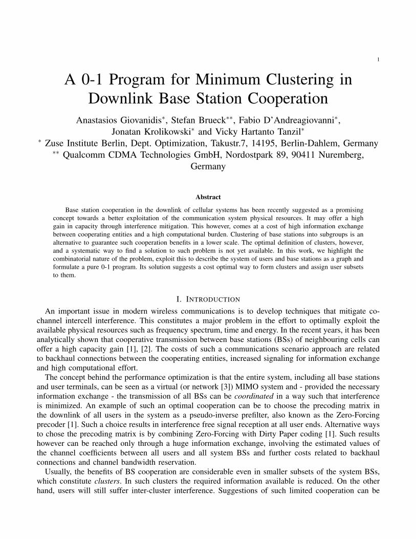
Figure 1: Example of a network topology with 4 Base Stations and 3 Users.
III. GRAPH MODEL AND CLUSTER DEFINITION
A. DefinitionsThe set of users and base stations, as well as their inbetween interaction, can be modelled as an
undirected graph G = {V , E}, where V is the set of nodes and E is the set of edges. The set of nodesconsists of two independent subsets: a) the set of User (U) nodes VU with cardinality N and b) the setof Base Station (BS) nodes VB with cardinality M . For these it holds VU ∪VB = V and VU ∩VB = ∅.
The set of edges further consists of two independent subsets: a) the set of U-BS edges
EU :={(u, b) |u ∈ VU , b ∈ VB
}(10)
as well as b) the set of BS-cooperation edges
EB :={(bi, bj) |bi, bj ∈ VB, bi 6= bj
}(11)
No edge between user nodes is considered and EU ∪ EB = E , EU ∩ EB = ∅. An example is shown inFig.1. A binary variable is assigned to each edge of the network:• Variable au,b ∈ {0, 1} is assigned to edges in EU .• Variable cbi,bj ∈ {0, 1} is assigned to edges in EB.
We define the set of ’active’ BS-cooperation edges such that
AB :={(bi, bj) ∈ EB | cbi,bj = 1
}⊆ EB
which is named Cooperation Set in what follows and the set of ’active’ U-BS edges such that
AU :={(u, b) ∈ EU | au,b = 1
}⊆ EU
which is named Assignment Set.
6
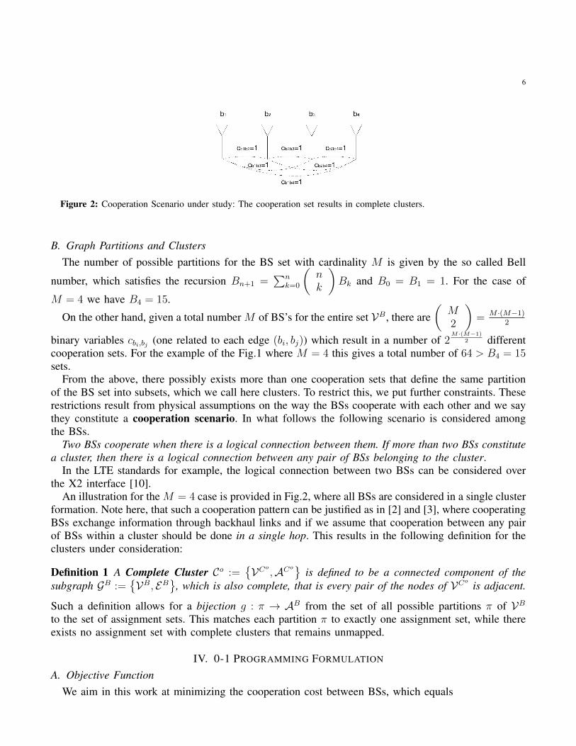
Figure 2: Cooperation Scenario under study: The cooperation set results in complete clusters.
B. Graph Partitions and ClustersThe number of possible partitions for the BS set with cardinality M is given by the so called Bell
number, which satisfies the recursion Bn+1 =∑n
k=0
(nk
)Bk and B0 = B1 = 1. For the case of
M = 4 we have B4 = 15.
On the other hand, given a total number M of BS’s for the entire set VB, there are(M2
)= M ·(M−1)
2
binary variables cbi,bj (one related to each edge (bi, bj)) which result in a number of 2M·(M−1)
2 differentcooperation sets. For the example of the Fig.1 where M = 4 this gives a total number of 64 > B4 = 15sets.
From the above, there possibly exists more than one cooperation sets that define the same partitionof the BS set into subsets, which we call here clusters. To restrict this, we put further constraints. Theserestrictions result from physical assumptions on the way the BSs cooperate with each other and we saythey constitute a cooperation scenario. In what follows the following scenario is considered amongthe BSs.
Two BSs cooperate when there is a logical connection between them. If more than two BSs constitutea cluster, then there is a logical connection between any pair of BSs belonging to the cluster.
In the LTE standards for example, the logical connection between two BSs can be considered overthe X2 interface [10].
An illustration for the M = 4 case is provided in Fig.2, where all BSs are considered in a single clusterformation. Note here, that such a cooperation pattern can be justified as in [2] and [3], where cooperatingBSs exchange information through backhaul links and if we assume that cooperation between any pairof BSs within a cluster should be done in a single hop. This results in the following definition for theclusters under consideration:
Definition 1 A Complete Cluster Co :={VCo
,ACo}is defined to be a connected component of the
subgraph GB :={VB, EB
}, which is also complete, that is every pair of the nodes of VCo
is adjacent.
Such a definition allows for a bijection g : π → AB from the set of all possible partitions π of VBto the set of assignment sets. This matches each partition π to exactly one assignment set, while thereexists no assignment set with complete clusters that remains unmapped.
IV. 0-1 PROGRAMMING FORMULATION
A. Objective FunctionWe aim in this work at minimizing the cooperation cost between BSs, which equals
7
∑(bi,bj)∈EB
kbi,bj · cbi,bj (12)
and kbi,bj are positive costs per connection (bi, bj). In what follows, the set of necessary constraintssubject to which the minimization takes place will be presented.
B. Assignment Variables in the Precoding VectorBased on the definitions in the previous section and the discussion on the downlink transmission in
Section II, we will from now on replace the beamforming vector for user u by the binary assignmentvector and formulate clusters considering average SINR. Precoding can be applied as a second step,after the clusters have been determined.
wu := [au,1, . . . , au,M ]T (13)
The products in (9) take the form
w†nRuwn · pn =∑b
an,b · g2u,b · pn (14)
where we make use of the fact that a2n,b = an,b. From this, user n contributes to the interference part ofuser u’s receive signal, through all BSs b assigned (an,b = 1). Assignment reserves pn power from BSb.
C. Power ConstraintsIt was mentioned in Section II that the power expenditure per BS is given in (1). It is reasonable
to consider an upper bound Pb on the power consumed per BS. Another, reasonable assumption (seealso the Linear Wyner Model in [3]) is to consider equal power consumption per user served within acell. Then instead of pu, which is the signal power of user u, we can consider pb to be the fixed powerbudget contributed by BS b to each user u assigned to it. Then the power constraint (1) is reformulatedas
∑u
au,b · pb ≤ Pb ⇒∑u
au,b ≤ bPbpbc := Kb, ∀b (15)
which sets a bound Kb on the number of users served per cell. Furthermore, given Kb, the per BScontribution belongs to pb ∈ ( Pb
Kb+1, Pb
Kb].
D. SINR ConstraintsUsing the auxiliary variables and (14), and replacing pu by pb as explained above, we can reformulate
the SINR constraint per user in (5) as a knapsack inequality with real valued coefficients.∑n∈VU
∑b∈VB
run,b · an,b ≥ 1, ∀u (16)
where
run,b :=g2u,b · pbσ2u
·{
1γu
, if n = u
−1, if n 6= u(17)
8
E. User Assignment and CooperationGiven the above definition of complete clusters, there should be a logical connection between any
two BSs taking part in the service of a user. When there is no connection between two BSs, then theseshould belong to different clusters, and the user should not anymore be assigned to both of them. Toformalize this idea we introduce the inequality
cbi,bj + 1 ≥ au,bi + au,bj , ∀u, bi, bj (18)
This has the following effect:• When cbi,bj = 0, the user can be assigned to at most one of the two BSs.• When au,bi = au,bj = 1, the BSs should cooperate (cbi,bj = 1).
F. Complete Cluster ConstraintsSince we restrict the clustering to complete only clusters as defined in the previous section, extra
constraints should be introduced.
cbi,bl + 1 ≥ cbi,bj + cbj ,bl , ∀bi, bj, bl (19)
Proposition 1 The set of inequalities (16), (18) and (19) guarantee that:1) All feasible clusters are complete by Def.1.2) A feasible solution assigns a user to exactly one cluster.
Proof: For Prop.1.1. it is sufficient to show that, the case where two BSs bi, bl ∈ VB are connectedand have distance equal to 2 is infeasible, since every path of length ≥ 2 has a subpath of length 2.Suppose, it can be feasible. Then, there exists a BS bj with distance cbi,bj = cbj ,bl = 1 from bi and blrespectively, so that the path has distance 2. Using (19), cbi,bl = 1 and hence there exists a path frombi to bl with length 1, which is a contradiction.
For Prop.1.2. suppose it is feasible to assign user u to 2 clusters. Then there exist BSs bi and bj suchthat, au,bi = au,bj = 1 and cbi,bj = 0 (complete clusters from Prop1.1.). By (18), cbi,bj = 1, which is acontradiction. Assignment to at least one cluster comes from the fulfillment of the SINR constraint in(16).
The proposition that follows explains that, the optimal solution provides minimum size clusters, inthe sense that another partition which results by reallocating a single BS from one cluster to another iseither infeasible or suboptimal.
Proposition 2 When kbi,bj := 1, the solution of
min∑EB cbi,bj
s.t. (15)-(19) (20)
satisfies Prop.1 and partitions VB into clusters such that:• Reallocation of a single BS from a larger cluster to a smaller one is infeasible (unless the cardinality
of the two clusters differs exactly by 1 in which case the cost is equal to the optimal).• Reallocation of a single BS from a smaller cluster to a larger one is always suboptimal.

9
Proof: Let the BS subset forming cluster e be denoted by VCo
e . The optimal partition is π∗ andconsider elements (clusters) of it a and e, such that |VCo
a | > |VCo
e |.For the first case, the partition is denoted by π− and the resulting elements by a− and e− respectively.
The change in total cost equals∑(bi,bj)∈ACo
a−
cbi,bj +∑
(bi,bj)∈ACo
e−
cbi,bj =
∑(bi,bj)∈ACo
a
cbi,bj +∑
(bi,bj)∈ACoe
cbi,bj −|VCo
a− |+ |VCo
e |
Since |VCo
e | − |VCo
a− | ≤ 0 with equality only in the case where |VCo
a | = |VCo
e | + 1 the cost will furtherreduce from the optimal, which implies that the new cluster set is infeasible (except from the equalitycase).
For the second case, the partition is denoted by π+ and the resulting elements by a+ and e+
respectively. Following the above calculations, the change in cost will equal |VCo
a | − |VCo
e+ | > 0, andsuch a solution is always suboptimal.
V. SOLUTION AND NUMERICAL RESULTS
For the solution of the problem in (20), we have initially used the ZIMPL programming language[11] to translate the model into a 0-1 integer program. As a next step, the open source mixed integerproblem solver SCIP [12], which implements Branch-and-Bound, was used to derive the 0-1 solution,for the optimal assignment and cooperation variables.
A. Scenario with 16 BSs and 16 UsersFor simulation purposes we have created a platform, based on the Java programming language, which
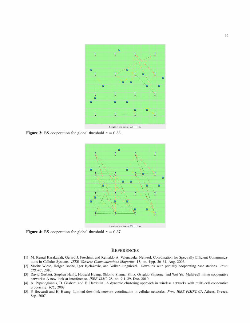
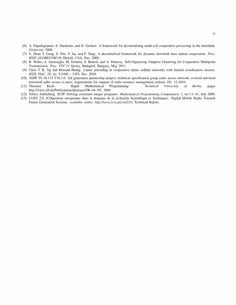
produces automatically a map of 16 fixed BSs and 16 users uniformly scattered on the 2D-plane. Theper antenna constraint is set to Pb = 40W , ∀b and each BS is able to serve at most Kb = 3 users. Thenoise variance is set to σ2 = −174dBm/Hz. The long term channel fading coefficients are estimatedusing the COST-Walfish-Ikegami model for urban environments [13] depending on the distance of theuser to each of the BSs. The SINR threshold is the same for all users and is allowed to vary within theinterval γ ∈ [0.2, 0.4]. Fig.3 and Fig.4 provide two examples, where it is illustrated how the cooperationbetween BSs changes, as the per user SINR demand increases from γ = 0.35 to γ = 0.37. Clusteringshows to behave in a very sensitive way related to the increase in overall demand.
VI. CONCLUSIONS
In the current work, a 0-1 program for the optimal clustering of cooperating base stations in thedownlink has been suggested. The cooperation depends on the assignment of users to BSs for fulfillmentof their SINR requirement. To achieve this, the beamforming vector per user for the entire virtualMIMO system, has been treated as an assignment vector. Furthermore, the clusters are formed based ona cooperation scenario that requires a logical link connection between each cooperating BS pair, thusresulting in - so called - complete clusters. The objective is to define minimum cooperating groups ofBSs among all feasible solutions. Major drawback of the approach is its centralized implementation,which requires information over the entire long term channel matrix for all users in the system and theirdemands. Furthermore, its feasibility depends on the chosen user QoS demands to be supported. Sucha result can be used however as an optimal upper bound for all decentralized schemes suggested, whilethe formulation further gives insights to how BSs optimally cooperate and how clusters are formed.
10
Figure 3: BS cooperation for global threshold γ = 0.35.
Figure 4: BS cooperation for global threshold γ = 0.37.
REFERENCES
[1] M. Kemal Karakayali, Gerard J. Foschini, and Reinaldo A. Valenzuela. Network Coordination for Spectrally Efficient Communica-tions in Cellular Systems. IEEE Wireless Communications Magazine, 13, no. 4:pp. 56–61, Aug. 2006.
[2] Moritz Wiese, Holger Boche, Igor Bjelakovic, and Volker Jungnickel. Downlink with partially cooperating base stations. Proc.SPAWC, 2010.
[3] David Gesbert, Stephen Hanly, Howard Huang, Shlomo Shamai Shitz, Osvaldo Simeone, and Wei Yu. Multi-cell mimo cooperativenetworks: A new look at interference. IEEE JSAC, 28, no. 9:1–29, Dec. 2010.
[4] A. Papadogiannis, D. Gesbert, and E. Hardouin. A dynamic clustering approach in wireless networks with multi-cell cooperativeprocessing. ICC, 2008.
[5] F. Boccardi and H. Huang. Limited downlink network coordination in cellular networks. Proc. IEEE PIMRC’07, Athens, Greece,Sep. 2007.
11
[6] A. Papadogiannis, E. Hardouin, and D. Gesbert. A framework for decentralizing multi-cell cooperative processing in the downlink.Globecom, 2008.
[7] S. Zhou, J. Gong, Z. Niu, Y. Jia, and P. Yang. A decentralized framework for dynamic downlink base station cooperation. Proc.IEEE GLOBECOM’09, Hawaii, USA, Dec. 2009.
[8] R. Weber, A. Garavaglia, M. Schulist, S. Brueck, and A. Dekorsy. Self-Organizing Adaptive Clustering for Cooperative MultipointTransmission. Proc. VTC’11 Spring, Budapest, Hungary, May 2011.
[9] Chris T. K. Ng and Howard Huang. Linear precoding in cooperative mimo cellular networks with limited coordination clusters.IEEE JSAC, 28, iss. 9:1446 – 1454, Dec. 2010.
[10] 3GPP TS 36.133 V10.1.0. 3rd generation partnership project; technical specification group radio access network; evolved universalterrestrial radio access (e-utra); requirements for support of radio resource management (release 10). 12-2010.
[11] Thorsten Koch. Rapid Mathematical Programming. Technical University of Berlin, pageshttp://www.zib.de/Publications/abstracts/ZR–04–58/, 2004.
[12] Tobias Achterberg. SCIP: Solving constraint integer programs. Mathematical Programming Computation, 1, no.1:1–41, July 2009.[13] COST 231 (COperation europeenne dans le domaine de la recherche Scientifique et Technique). Digital Mobile Radio Towards
Future Generation Systems. available online: http://www.lx.it.pt/cost231/, Technical Report.