9c' -~ - lehigh universitydigital.lib.lehigh.edu/fritz/pdf/187_3.pdf · lehigh university,...
TRANSCRIPT

l \" \
/F~•.3 ~c
~& ~ ~9c'" -~/---''')
THE FATIGUE AND BENDING PROPERTIES OFCOLD DRAWN STEEL WIRE
By H. J. GODFREY
Abstract
The paper presents the results of an investigation onthe fatigue and bending properties of carbon steel wire.The special fatigue and bend testing machines developedfor this study are described ~n this paper. The effect ofwire drawing, decarburization and surface conditions onthe fatigue properties have been investigated. The bendtesting machine has been so designed that the severity ofthe bend test can be controlled in order to study the truebending properties of wire. M etallographic and X -raystudies of the internal structure of cold drawn wires areincluded in this paper.
INTRODUCTION
THIS investigation was primarily a study of the effect of coldworking on the physical properties of steel wire. In this study
the fatigue and bending propertIes as determined on especially designed testing machines have been emphasized.
Many investigators studying the wire rope problem feel that themost important stresses in a wire rope are those due to the repeatedbending of the ropes when passing around sheaves and drums. Thispoint of view has been challenged by others interested in this subject,since there are many factors other than actual stresses that help todetermine the life of a wire rope. These factors include corrosion,abrasion, and localized compression forces on the surface of wireropes and between the individual wires causing plastic flow to anextent which is generally not fully appreciated. However, the repeated bending stresses are important and a more complete knowledge of the fatigue properties of steel wire should lead to a bettercorrelation between the manufacturing process of wire ropes withtheir service life.
. The usual specifications for wire ropes include the tensilestrength and the bending properties of the individual wires. Accord-
A paper presented before the Twenty-second Annual Convention of theAmerican Society for Metals held in Cleveland, October 21 to 25, 1940. Theauthor, H. J. Godfrey, is engineer of tests, Fritz Engineering Laboratory,Lehigh University, Bethlehem, Pa. Manuscript received June 17, 1940.
1

2 H. J. GODFREY
ing to Bonzel (1),' the bend test is used in the mil1 to determine themal1eability of wire. Bonzel states that under the present methodsof bend testing it has been impossible to obtain an intelligent comparison between the results on a single wire in jaws of different radii ofcurvature. He also states that by .varying the curvature of bendingin accordance with some function of the wire diameter, it is impossible to get consistent results on wires in different stages of coldwork. Many persons interested in the physical properties of ropewire give little credence to the bend test as it is now performed in themill.
There are many factors affecting the bend test and since theconditions of testing have not been standardized there is little doubtas to the reason for the difficulty in interpreting the bend test results.In the design of the bend testing machine used in this investigation,as many unknowns as possible were eliminated.
The relationship between the bending and fatigue properties ofsteel wire is a debatable question. The bending of a wire around asmal1 mandrel is very different than the conditions which exist in afatigue test where the repeated bending stresses are in or slightlyabove the so-cal1ed elastic range of the material. However, in thisstudy on the effect of wire drawing on the physical properties of steel,both the fatigue and bending properties show a definite change intheir characteristics after a certain amount of cold working. Itshould be emphasized that the bend test cannot be substituted forthe fatigue test. Prof. H. F. Moore stated in the 1939 A.S.T.M.Marburg Lechlfe (2) that no confidence should be placed in ShOl'ttime fatigue tests. In this instance the bend test is by no means afatigue test and in no way may it be used to determine the actualfatigue properties of materials.
Von Ewald Buschmann (3) has attempted to determine thefatigue properties of materials by means of a bend testing machinesimilar to that described in this paper. The results of Buschmann'stests seem to be quite satisfactory for pure metals or al10ys in theannealed condition in which the material is uniform throughout.However, this test would not be satisfactory for materials that arenot uniform and whose fatigue properties are greatly affected bysurface conditions.
Sachs and Sieglischmidt (4) report that as far as the effects ofstrength are concerned, the present information and tests show that~figures appearing in parentheses refer to the hihliography appended to this paper.

COLD DRAWN WIRE 3
wires of a higher strength have a longer service life in spite of a correspondingly higher direct stress over the cross section. Since it hasbeen found that for a given type of wire the fatigue limit stress increases in proportion to the tensile strength, it is quite logical that theendurance of a high strength wire rope operating around a given sizesheave, will have a longer life than that of a lower strength ropearound the same diameter sheave even though the actual direct stressin each case is a given percentage of the tensile strength of the wire.Sachs and Sieglischmidt also found that carbon steels had no directrelationship between the bend test and the strength properties as wasfound to be true for simple metals and other metallic alloys.
WIRE FATIGUE MACHINE
The two wire fatigue machines used in this study were designedand built at the Fritz Laboratory. The principle involved in the
Thrust Be8rinrJ7"""::J'=======~Wire 8pecimen
Fig. I-Principle of \Vire Fatigue Machine.
design of these machines is the same as that used in the HaighRobertson rotating wire fatigue machine which is now quite familiarto those interested in this subject. Changes were made, however, inseveral of the details which have simplified its construction withoutany loss in the required accuracy.
The difficulty encountered in the fatigue testing of wire is instressing the wire specimen in such a manner that the test results arenot affected by the gripping of the specimen. This difficulty is surmounted by stressing the wire specimen as a rotating wire strut, theends of which are not fixed. Under this condition of loading thestresses vary from zero at the ends of the specimen to a maximumin the center of the column length. A diagrammatic view of the principle of the fatigue machine is shown in Fig. 1.
The stresses are compu,ted by the well-known "Euler" columnformula. The maximum stress at the center is equal to:
71"2 d£=-8-£
360 L

4 H. J. GODFREY
111 which:
f = bending stress-pounds per square inche = inclination at the end of the wire-degreesd = diameter of wire-inches .
L = length of wire-inchesE = modulus of elasticity in tension-pounds per square inch.
The above formula is a close approximation and directly applicablewhen the angle of inclination is small. When the angle is greaterthan twenty degrees the curve of flexure changes perceptibly and acorrection is necessary. However, for practically all fatigue testsmade on steel wire the angle of inclination is less than twenty degrees.
A photograph of one of the wire fatigue machines is shown inFig. 2. The machine consists of a base on which a motor is placedat one end and an adjustable tail stock at the other end. The wirespecimen is held at one end by a chuck fitted to the shaft of theelectric motor and by a thrust bearing at the other end. A specialcap is fitted on the end of the wire which runs in the thrust bearing.In order to bend the wire to any desired angle of inclination an endthrust is applied by turning the tailstock. Simultaneously, the motorrotates the wire on its own axis, thus causing a complete reversal ofthe bending stress for each revolution.
The motor is placed in a swinging frame in such a position thatthe end of the chuck is exactly at the center of rotation of the frame.The counterweights on the swinging frame balance the weight of themotor. The angle of inclination is measured by a scale and vernierreading to 0.05 degrees, which for steel, corresponds to a stress ofapproximately 300 pounds per square inch for an Lid ratio of 150.When the specimen fractures, the swinging frame is thrown off balance and a mercury switch automatically stops the motor. The speedof testing used in these experiments was approximately 5000 revolutions per minute.
The stresses due to the dead weight of the specimen are notcalculated as such, since the total stress is computed from the actualstrains as measured by the angle of inclination. There is a smallerror caused by the fact that for a given stress at the center of thespecimen the angle of inclination, due to the dead weight of the specimen, is not the same as that determined by the Euler formula. However, this difference is so small that it has no influence on the test
results.

Fig. 2-Rotating Wire Strut Fatigue Machine.

6 H. J. GODFREY
W IRE BENDING MACHINE
The wire bending machine was designed and made in the FritzLaboratory, and is shown diagrammatically in Fig. 3. A photographof the bending machine is shown in Fig. 4. The wire is held ingrips attached to the bending arm and weights are suspended at the
1#1'6' .Specim:n
SuspendedWeight
Fig. 3-Principle of WireBending :Machine.
lower end of the wire. The wire is then bent back and forth overthe rollers by moving the bending arm through an angle of ]80 degrees. These rollers are supported on bearings so that they are freeto rotate during the bending operation. The rollers can be adjustedso that the clearance between them is slightly more than the diameterof the wire. The center of rotation of the bending arm is at a pointO.7R above the center of the rolls, where R = the radius 0 t therollers. In this position there is very little vertical movement of thewire during the bend test. For the various sizes of rollers used thebending arm may be adjusted to the proper elevation.
The bending machine is operated by hand and the speed of testing of fifty ISO-degree bends per minute is controlled by a Metronome. The direct tensile stress in the wire specimen, due to the suspended weights, is equal to one per cent of the tensile strength of thewire. Three or four specimens were tested to failure for each rollsize and the average number of bends were used to compare thebending properties of the various niaterials.

COLD DRrllVN WIRE
Fig. 4-Wire Bending ~Iachine.
7

8 H. J. GODFREY
MATERIALS
The physical properties of the materials included in this investigation on the fatigue and bending properties of cold drawn steel wire
Table ITensile and Fatigue Properties of Cold Drawn Steel Wire
Carhon Diam- Tensile Elong. in Fatigue FatigueContent eter Per Cent' Per Cent* Strength 10 In. Limit Ratio
Per Cent In. Reduction Elongation P.s.i. Per Cent P.s.i. Per Cent0.05 0.215 0 0 45,900 24.00.05 0.134 61.2 157 75,500 4.4 36,000. 47.60.05 0.112 73.0 269 84,000 3.2 39,300 46.80.05 0.062 91.7 1104 105,000 1.6 40,100 38.2
0.16 0.215 0 0 59,700 21.50.16 0.135 60.5 154 92,000 3.7 39,600 43.00.16 0.112 73.0 269 101,400 3.25 42,000 41.40.16 0.062 91.7 1104 128,000 1.15 43,400 33.9
0.39 0.205 0 0 101,500 9.00.39 0.136 56.0 127 135,000 4.6' 47,000 34.80.39 0.113 69.6 229 148,000 4.3 55,800 37.70.39 0.062 91.0 994 208,000 1.6 60,400 29.0
0.58 0.139 0 0 144,500 9.5 45,200 31.20.58 0.106 41.9 72 171,500 6.1 55,800 32.50.58 0.081 65.9 195 195,000 5.6 63,500 32.50.58 0.061 80.6 418 227,000 2.9 64,500 28.4
0.90 0.147 0 0 212,000 7.5 68,200 32.20.90 0.124 28.8 41 222,000 6.8 72,500 32.60.90 0.102 51.9 108 239,000 5.9 79,000 33.00.90 0.085 66.6 199 258,500 4.4 83,600 32.40.90 0.077 72.6 264 272,000 3.8 90,000 33.1
Polished Wire0.05 0.112 73.0 269 84,000 3.2 43,000 51.20.16 0.112 73.0 269 101,400 3.25 46,000 45.40.39 0.113 69.6 229 148,000 4.3 63,000 42.60.58 0.106 41.9 72 171,500 6.1 61,000 35.60.90 0.124 28.8 41 222,000 6.8 85,000 38.3
-.:ilYWire Drawing.
are presented in Table 1. This material was analyzed for its carbonand manganese content and the results are as follows:
CarbonPer Cent
0.050.160.390.580.90
ManganesePer Cent
0.110.490.750.600.35
The 0.05 and 0.16 per cent carbon wires were drawn from ahot-rolled green rod to the various wire sizes. The 0.39 per centcarbon material was drawn from a lead-patented rod and the highcarbon material was drawn from wire which had been given an in-

COLD DRAWN WIRE 9
termittent patenting. Although the exact temperatures of heat treatment were not available, it will suffice to say that the patenting processusually consists of quenching in lead to 900 to 950 degrees Fahr.(480 to 510 degrees Cent.) from above the critical temperature.
Table IITensile and Fatigue Properties of Decarburized Cold-Drawn Steel Wire
Carbon Diameter Tensile Fatigue FatigueContent ,---Inches~ Per Cent* Strength Limit Ratio
:Material Per Cent Net Gross Reduction P.s.i. P.s.L Per Cent0.73 0.095 50.5 202,000 46,000 22.8
Plain 0.73 0.085 59.9 215,000 52,000 24.10.73 0.074 70.0 228,000 54,000 23.60.73 0.060 80.0 240,400 60,000 24.9
Average 23.8
Electro- 0.73 0.1035 0.1065 48.1 185,000 47,000 25.40.73 0.081 0.083 68.5 213,000 50,000 23.4Galvanized 0.73 0.070 0.072 76.4 236,000 54,000 22.9Wire 0.73 0.0585 0.060 83.5 243,000 58,000 23.9
Average 23.9
Hot Galvanized0.190 0.194 235,000 48,000 20.4Bridge Wire
*By vVire Drawing.Ail Values Computed on the Net Diameter of Wire.
The material used in a supplementary study is presented 111
Table II. The chemical analysis of this wire is as follows:
Bare WireElectro
Galvanized
Carbon0.73
0.73
Manganese Phosphorus0.65 0.028
0.56 0.026
Sulphur0.025
0.025
Silicon0.19
0.18
The 0.73 per cent carbon material was lead-patented before drawing.The hot-galvanized wire included in Table II is cold-drawn bridgewIre.
DISCUSSION OF TEST RESULTS
M etallographic Study-The metallographic examination of thematerial included in Table I was made to determine the structure ofthe rod before being drawn into wire and also to determine to whatextent the surface of the material was decarburized. The photomicrographs of the 0.05, 0.16, 0.39, 0.58, and 0.90 per cent carbonmaterial are presented in Fig. 5. The photomicrographs at one hundred magnification show that there is little or no decarburization onany of these materials. There were no further heat treatments onthis material during the following stages of wire drawing.

10 H. J. GODFREY
Fig. S-Photomicrographs of Hot·Rolled and Patented Steel Rods. X 100. a.-O.OSPer Cent Carhon; b.-0.16 Per Cent Carbon; c.-0.39 Per Cent Carbon; d.-0.S8 Per CentCarbon; e.-0.90 Per Cent Carbon.
The 0.73 per cent carbon wire in Table II was included in thisinvestigation in order to study the effect of c1ecarburization on thefatigue properties of wire. The photomicrograph in Fig. 6 shows adistinct ring of decarburized material at the surface of the bare wire.Since the patented wire was not available for examination this photomicrograph was made from the 0.095-inch diameter wire drawn 50.5per cent reduction. A tudy of the depth of decarhurization was

also made on the 0.73 per cent carbon electro-galvanized wire andthe result were as follows:
It should be noted that the amount of decarburization was about thesame for both the bare and electro-galvanized 0.73 per cent carbonwIre.
A metallographic study of the cold drawn hot-galvanized bridgewire also showed a distinct layer of decarburized material beneath thehot galvanized coating.
Tensile Properties-In a study on the effect of cold working onthe properties of steel an expression for the amount of cold workshould be formulated. In the manufacture of steel wire the amountof cold working by wire drawing is u ually expressed by the per cent
11
Minimum0.0050.0060.0070.004
0.0110.0100.0090.008
Maximum
Electro-Galvanized 0.73 Carbon VvireDecarburization
,.-------Inches----~
COLD DRAWN WIRE
Fig. 6-Photomicrograph of Decarburized 0.73 Per Cent Car·bon Steel \'Vire. X 100.
et DiameterInches0.10350.08100.07000.0585

12 H. J. GODFREY
reduction in area of the original rod or patented wire. This IS expressed by the equation:
Ao-A fPer cent Reduction = 100 XAo
where Ao = original areaA f = final area
Another means of expressing the amount of cold working is bythe per cent elongation by wire drawing which is found as follows:
Per cent Elongation = 100 X Ao At At
This expressIOn shows the amount that the wire has been stretched
E80 r--~-"---.-~------,--,...--...,..----,-----r---,
2401--+--
~8 EOO 1---j---+-----+--+--+---+-----::7'"'!""-----+----l-----1~
~~ 180 1---+------:::::::;;:;j;--"""'F---+---j--+---4------:~l--__!__j
~~
~ 120 f----t---t-=;..-+-='==-j---j----j---I----t--::7'4--l
~
802010 3D 40 50 80 POReduction by Wire-Drawing, %
Fig. 7-Effect of \Vire Drawing on Tensile Strength of Steel \Vire.
40 L...-_-'----_...L.-_....l-_-l..-_---l.-_----l..._--l._----l__L-...l
o
or elongated by the wire drawing process. This value could reachinfinity for a material with perfect ductility and often reaches as highas 3000 per cent. For example, an elongation of 1000 per centmeans that the wire has been drawn eleven times its original lengthand is equal to 90.9 per cent reduction in the cross sectional area.
The relation between the tensile strength of steel wire and theper cent reduction by wire drawing and per cent elongation by wiredrawing is shown in Figs. 7 and 8. From these two figures it appears that the amount of cold working is more logically expressedby the percentage elongation since in this case, the tensile strengthincreases at a greater rate at the initial stages of wire drawing, where-

COLD DRAWN WIRE 13
240 380 480 800 PeO 840 980 1080Elofl{j8tion by Wipe-Drawing, %
leD
/-"i1.--0 I,.....090 Carbon
~ ~ \..058 Carbon__0
V" l---l---/ ---l---17
o~oI.--- t039 Carbon
/"IOJ8Carbon"'), ~
17 l-o- -"
~~----- ~ Q I
V V °r~i04D o
80
as when related to the per cent reduction, the tensile strength increases at a more rapid rate during the final stages of wire drawing.However, since it is general practice to use the per cent reduction bywire drawing for comparative purposes, all other values in this report are compared on this basis.
280
Fig. 8-Effect of Wire Drawing on Tensile Strength of Steel Wire.
Fatigue Properties-The fatigue properties for the wire freefrom decarburization are shown in Table I, along with the otherphysical properties as determined by the tensile test. This materialwas machine-straightened before any of the physical properties weredetermined. . This straightening operation was performed so that aperfectly straight specimen could be used in the rotating wire strutfatigue machine. A number of tensile and fatigue tests were madeon both machine and hand-straightened wire and it was found thatthe machine straightening process did not affect the test results toany appreciable amount.
The actual endurance curves for the carbon steels in Table Iare presented in Figs. 9 to 13. These curves are presented mainly toshow the effect of the carbon content on the characteristics of thefatigue curves. It should be noted that for stresses just above thefatigue limit the low carbon steels undergo a great many more cyclesbefore fracturing than the high carbon steels. For example, a 0.05per cent carbon wire fractured after nine million stress-cycles, where.-

°~
.""-.r-... ~
~t'-.t:; °~~o
1".°1
°° ~-a06?"r.l-40!00Psi.
~ ~/f!:0!!'?"H -J!lOOOPsi.
"° i'.r "- Jli.a.~0l1! H -J6000Psi..
,
14
48
JBJOs
H. J. GODFREY
J08 JO?Cycles to Fa/lure
Fig. 9-Fatigue Test on 0.05 Per Cent Carbon Steel \Vire.
J08
55
t---=:I-!'- .J
0 ~~ !o--...~ ....... t-"t-- f!!:. 0 OBi?" F.L. -';3400 Psi.
1--. . Jl£-JJiJ" FL. -41'000 Psi.t--rz r;iO,J· ,NHW'"
J08
of theThese
Cycles to fBilureFig. 10-Fatigue Test on 0.16 Per Cent Carbon Steel Wire.
as the maximum number of cycles before fracture for a 0.90 per centcarbon wire was slightly over one million cycles. The intermediatecarbon steels ranged between these two limits. Gill and Goodacre( 5) report that five million cycles were sufficient to indicate thefatigue limit of wire. Since their tests included only materials witha carbon content of over 0.36 per cent, their analysis was correct forthe material investigated. However, the true fatigue limit for verylow carbon steels should be determined from tests of over 10 millioncycles in duration. Fractures in other metals such as aluminum takeplace after 100 million cycles of stress.
The effect of wire drawing on the fatigue propertiesmaterial free from decarburization is presented in Fig. 14.

COLD DRAWN WIRE 15
"0.i'-.... 0
0
I ~f;::o.
~ 01a.-0062' F.L.·B0400 Psi
r-....0
r---I'-- :----... Ola={l!/J" n·6S800 Psi
.............. III -II J1L--o.r-.,. IJI8.=01J8' n·4?OOOPSI.
III ~10?
Cycles to F81/UI'S
lOB
Fig. II-Fatigue Test au 0.39 Per Cent Carbon Wire.
~- 1.- ..... x
~~x x .018.·0081' F.L. -84600 PIli.. r---.: ~:x.-. .ole.-OOB1' F.L. ·83500Psi.- '-.... ...... .o10.-0.10S" F.L.-55800 Psi
0II··~
............... Dle.-o.1iJ9' F.L.-45,};0 Psi.
i 11--4D
IDSCycles to Failure
Fil(. 12·-Fatigue Test on 0.58 Per Cent Carbon Steel Wire.
curves show that the fatigue properties of steel wire increase withcold working, although the rate of increase is not always in proportion to the amount of wire drawing.
The relationship between the fatigue limit stress and the tensilestrength of steel wire is of importance. The fatigue limits as compared to the tensile strength of the various carbon steels are shownin Fig. 15. On first sight it would appear that the fatigue limit isapproximately a function of the tensile strength of the material regardless of the carbon content. However, when we note the ratiobetween the fatigue limit and the tensile strength as shown in thelast column of Table I we find that this ratio (hereinafter termedthe fatigue ratio) decreases with an increase in carbon content. Thisrelationship is presented in Fig. ]6. The solid line is an average forall the materials which have been wire drawn less than 75 per cent

16 H. J. GODFREY
/08
~jo "",0
,,,",,....... ,,-
~t--a; '., T 1-.. Dia.·OOP?' FL.-90000 Psi.
"'- '., r--.r,,· oia.-~lJTT: ;.kJJ, "- 0;,·I"--x 1'-.. . .:- - :T.018.-0102 F.L.-?9000PsI.
~ I"- 0 /111'- 1 J_'',,- 0
0 Oia.·OIN- F.L.-?2500 Psi.,~ o-x 0Ji1..0T1f.£/.088200 Psi
80/05
!!O
Cycles to Fa/lureFig. 13--Fatigue Test on 0.90 Per Cent Carbon Steel Wire.
90
I/0
--/090 Carbon, ----'" f-O"
l..---- i----"\--
--t--'058C8~~
!--~0_
---l--- ~039Carbon
t~V- -?
0/8 Carbo~.-". ~1-0 0
0.05C8rbon~
o /0 20 30 40 50 130 POReduction by mi>e-lJrawing. %
80 90
Fig. 14-Effect of Wire Drawing on Fatigue Limit Stress of Steel Wire.
reduction. The dashed line represents material drawn over 80 percent reduction. It should be noted that the ratio between the fatiguelimit and the tensile strength for the 0.90 per cent carbon wire isabout the same value as for the 0.58 per cent carbon material. Thereason for the lowering of the fatigue limit ratio with an increasein carbon content is one of conj ecture. H. J. Gough (6) states thatthe fatigue limit can be correlated only to the ultimate tensile strengthand that no adequate reason can, at present, be considered to account

COLD DRAWN WIRE 17
/DBO Caf'bon7 .
l.r
D58 Caf'bon-y_.
DJ9C81'bL.....rV-.
1/,r"1~Q 18 Carbon
/"'-005 Carboni40
satisfactorily for the correlation observed and should be regardedonly as affording a useful empirical and approximate rule.
The lowering of the fatigue limit ratio with an increase in carboncontent may be due to surface conditions or to the inherent properties
BO
o 80 !CD t80 cOD NO c8078nsi/e 8tf'ength. fOOD Psi.
Fig. lS-Reiation Between Fatigue and Tensile Strength ofSteel Wire.
of the material. It is also noted that these materials of various carboncontent showed a considerable drop in the fatigue ratio when coldworked over 80 per cent reduction by wire drawing. These resultsare also included in Fig. 16, along with the amount of cold work.Gill and Goodacre (7) found in both decarburized wire and wire freefrom decarburization that the fatigue ratio was lowered when coldworking was excessive. The 0.90 per cent carbon wire did not showany lowering of the fatigue ratio since it was only drawn to 72.6 percent reduction.
Fatigtt'e tests were also made on wires of five different carboncontents polished to 000 emery and the results are shown in Table 1.In every case the fatigue properties were improved by the polishing.However, the decrease in the fatigue ratio with an increase in thecarbon content is still evident in the polished wires.
The hardness of the material cannot be related directly to thefatigue properties since the fatigue ratio remains practically constantfor the 0.90 per cent carbon wire from the patented condition up to72.6 per cent reduction. From this phenomenon it is apparent that

18 H. J. GODFREY
the fatigue properties are dependent on some inherent characteristicother than hardness.
The physical properties of the decarburized wire were determined from hand-straightened specimens and are presented in TableII. The fatigue ratio of the bare wire averaged about 24 per centwhich is considerably under the fatigue ratio of approximately 33 per
OPO 030 040 050 OBO OPO 080 0.90Caf'bon Content, Pef' Cent
010
JNumber8 !'emf' to jJef'ctmt?Jol~ f'eduction by w/i>e-dr8wing
~5?30 0 i'-...
91.7 ............
~0"
... ,9l;.......
0...........
" 58.1 N!9-65.9 fl9-?.?.61" t?8.B-68.6' ....
0.0
0, 0.0_
''Bto----- ----0 I_
I 80.r
045
025o
050
Fig. 16·-Relation Between Fatigue Ratio and Carbon Content of Steel Wire.
cent for the 0.90 carbon and 0.58 carbon wire free from decarburization. The electro-galvanized material which had the same chemicalcomposition as the bare wire had an average fatigue ratio of approximately 24 per cent which is the same value as that of the decarburizedbare wire. The reason for this low fatigue limit is naturally explained by the decarburized surface of this material. Since the material at the surface is practically free from carbon, the fatigue limit islowered to the extent of that of a low carbon steel. Once the fatiguecrack starts in this material, it will progress throughout the highercarbon core since at the base of the fatigue crack the stresses areextremely high. The electro-galvanized wire had the same averagefatigue ratio as the bare wire, indicating that the fatigue propertiesof this material are not affected by the electro-galvanized coating.
For general interest we have included the results of fatiguetests on cold drawn hot-galvanized bridge wire. The fatigue limitstress for this material was found to be 48,000 pounds per squareinch, which corresponds to a fatigue ratio of 20.4 per cent, based on

COLD DRAWN WIRE 19
the net diameter of the wire. Based on the gross diameter, the ratiowould be 1 per cent higher. The extremely low fatigue ratio is probably due to both the effect of decarburization and the hot-galvanizedcoating.
The bending fatigue limit of heat treated galvanized bridge wirewas found to be 50,000 pounds per square inch by Shelton andSwanger (8) or a fatigue ratio of 22 per cent. The fact that thefatigue stresses in suspension bridge cables are relatively low, probably account for the fact that cold drawn hot-galvanized bridge wire
20 ,--.....,---,---,------,--r---.....,---,---,---,
18 1---\-----:. t----j---_t---::7.c---..,---t--::;7""'~'--+------i
~~~ ~ Ie r----+-f. --+_-;;F----II------::>~~-_t_--+---_t--_+-_j
~~';:::lb~~ 8. r--I~7'" -~If6----+---+--+_--I------+---+-----j
+ Patented Rod.i:', • e8.8 %Reduction~~ D~%
4 t-:cg-t--'--+----+---+---+--- .. 68.6 %0;72.6 %
160 18014080 80 100 leaNumber of180 0 Bends
40cOO'--_--'--_-L_----'__-'---_--L.-_---l.__-'--_--'-_--'
a
Fig. 17-Relation Between Roll Wire Ratio and Number of Bends for 0.90 PerCent Carbon Wire.
tI~.
I
has proved to be a satisfactory material for this purpose. However,the fatigue properties of wire in the main cables of suspensionbridges should be maintained at the highest possible level.
Bending Properties-The wire bend test as carried out in thisinvestigation was designed to study the effect of wire drawing on thebending properties of steel wire. The number of I80-degree bendsthat a wire can withstand before fracturing is used as the criterionfor the relative bending properties. The severity of the bend test,as measured by the ratio of the roll diameter to the wire diameter,was also investigated. The ratio will hereinafter be termed the rollratio.
The bend tests were made on the material included in Table 1.This material was straightened by hand before testing. The resultsof the bend tests on the 0.90 per cent carbon wire are presented in
20 H. J. GODFREY
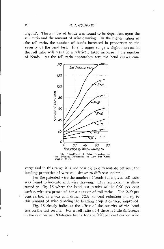
Fig. 17. The number of bends was found to be dependent upon theroll ratio and the amount of wire drawing. In the higher values ofthe roll ratio, the number of bends increased in proportion to theseverity of the bend test. In this upper range a slight increase inthe roll ratio will result in a relatively large increase in the numberof bends. As the roll ratio approaches zero the bend curves con-
/20 I----t---H'---t------j
/00 I----t--+-+--/--j---'-----j
~.
~~ 80 I---++--+-t---?"''f-------l..~"<::
1:, 80 I---+---+t'---;-f----t-:......."---f
~~~ 40 :f----,!-----A------c,-<--i----+-c=,.......---f
OL..-._-l..-_--'-_---'-_---'o I'D 40 80 80Reduction byWire-Drawing, %
Fig. 18-Effect of Wire Drawing onthe Bending Properties of 0.90 Per CentCarbon \Vire.
verge and in this range it is not possible to differentiate between thebending properties of wire cold drawn to different amounts.
For the patented wire the number of bends for a given roll ratiowas found to increase with wire drawing. This relationship is illustrated in Fig. 18 where the bend test results of the 0.90 per centcarbon wire are presented for a number of roll ratios. The 0.90 percent carbon wire was cold drawn 72.6 per cent reduction and up tothis amount of wire drawing the bending properties were improved.
Fig. 18 clearly indicates the effect of the severity of the bendtest on the test results. For a roll ratio of 4 there is little differencein the number of ISO-degree bends for the 0.90 per cent carbon wire
COLD DRAWN WIRE 21
drawn from zero to 72.6 per cent reduction. As the severity of thebend test is lessened by increasing the roll ratio a large difference inthe bending properties of the wire is observed. It should be expectedthat the bending properties of wire should change with the amountof cold working by wire drawing. The flexibility of this bend testapparatus makes it possible to explore the bending properties of wirevery much more completely than can be done by the conventionalbend test apparatus.
20 .--..,.-------,------,--..,..---,-----,--T"?-"---,-----,
t
16 1----+---+--_I_--+---bo""'=----.:I>-'''---+--_I_---1
J~l Ie 1----+----j4--~~~=----I-----+---+--_I_---1:::::::~~·s
8 I---""*--T".~"'-t_=_-_+__--f__-_+__--f__-_+__--f__-__j
• P8tented Rodo 58.0 % Reduction
4 I---E--t---j----j-----j----f-- " SB.B %o 91.0 %
150 18014060 80 100 leONumber of180 0 BendS'
40eO0'----'---'----'---'----'---'----'---'--_-'
o
"Fig. 19-Relation Between Roll Wire Ratio and Number of Bends for 0.39 PerCent Carbon Wire.
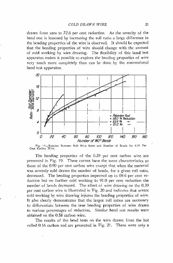
The bending properties of the 0.39 per cent carbon wire' arepresented in Fig. 19. These curves have the same characteristics asthose of the 0.90 per cent carbon wire except that when the materialwas severely cold drawn the number of bends, for a given roll ratio,decreased. The bending properties improved up to 69.6 per cent reduction but on further cold working to 91.0 per cent reduction thenumber of bends decreased. The effect of wire drawing on the 0.39per cent carbon wire is illustrated in Fig. 20 and indicates that severecold working by wire drawing injures the bending properties of wire.It also clearly demonstrates that the larger roll ratios are necessaryto differentiate between the true bending properties of wire drawnto various percentages of reduction. Similar bend test results wereobtained on the 0.58 carbon wire.
The results of the bend tests on the wire drawn from the hotrolled 0.16 carbon rod are presented in Fig. 21. There were only a

22 H. J. GODFREY
fS 60 1----1--7"""1--+---+----1~
r::l:'i..<::::>~ 40 1-..-L--+-----rc-+----!I---\-----1'cs~~ 20 1.-=--+-- '~~_o-t-._-1---1
~ b::~--I----,±-:--o-j--OL-_.L-_.L-_.L-_.L--
o PO 40 60 80 100Reduction by Wif'B-Drawing, %
Fig. 20-Effect of \Vire Drawing on the Bending Properties of 0.39 Per Cent Carbon Wire.
,//'
[;,~VA
/V~~
./v;Vt""~
liV/CD 805 %ReductionA?3.0% -I-
f---l o 9/.?% -H-
I I
20
16
4
oo PO 40 80 80 100 leO
Number of 1800 Bends140 180 /80
Fig. 21-Relation Between Roll \Vire Ratio and Number of Bends for 0.16 PerCent Carbon \Vire.
few bend tests made on the hot-rolled rods since it was not possibleto make a satisfactory test on this material. Bonzel (9) states thatin patented wire the number of bends increases after the first fewdrafts and in the case of mild steel the number of bends decreaseswith wire drawing. The few bend tests made on the hot-rolled rodsseem to confirm this statement. The bend test curves as presented inFig. 21 have the same characteristic shape as those of the patentedsteel wire although none of the material tested was cold drawn lessthan 60 per cent reduction. This material shows a sharp decrease inthe number of bends when cold drawn to 91.7 per cent reduction.

COLD DRAWN WIRE 23
Fig. 22 shows the effect of wire drawing on the bending properties of the various materials tested. AII of the bend curves with theexception of the 0.90 per cent carbon wire shows a distinct loss in
140 ...------,-----,--,-----,.-------,
120 f-------+---+--:¥-"""""---+----j
100
~
~ 80..~"=:
1:; 60
~§ 40<:
co I----+---+---+---+----j
R·Ro//RatioO'---...l...---'---'--------'o 20 40 80 80 JOO
Reduction by Wire-IJrawing, %
Fig. 22-Effect of Wire Drawing on the Bend.ing Properties of Steel \Vire.
the bending properties after severe cold drawing. The 0.90 per centcarbon wire was wire drawn 72.6 per cent, the 0.58 per cent carbonwire 80.6 per cent and all the other material over 0.90 per cent reduction. These tests show that the bending test can be used to differentiate between the true bending properties of wire, if the severity ofthe bend test is properly controlled.
GENERAL DISCUSSION OF TEST RESULTS
In this investigation the fatigue and bending properties of steelwire have been studied. The test results show that both the fatigueand bend tests as carried out in this investigation, can be used tostudy the effect of cold working on the physical properties of wire.The fatigue properties were found to increase in proportion to thetensile strength of the wire up to a critical amount of wire drawing,

24 H. J. GODFREY
Fig. 2J-Photomicrograph of Cold·Drawn 0.05 Carbon and 0.58 Carbon Steel Wire.X 100. a.-0.05 Per Cent Carbon. 61.2 Per Cent Reduction. b.-0.05 Per Cent Carbon.91.7 Per Cent Reduction. c.-o.58 Per Cent Carbon. 41.9 Per Cent Reduction. d.-O.58Per Cent Carbon. 80.6 Per Cent Reduction.
at which point both the fatigue and bending properties show a decidedchange.
COLD DRAWN WIRE 25
A metallographic study of the cold drawn wire was made onthe 0.05 and 0.58 per c~nt carbon wire and the photomicrographs areshown in Fig. 23. These illustrate the effect of cold drawing on thestructure of steel wire. The extreme amount of fibering is clearlyshown in the 0.05 per cent carbon wire drawn 91.7 per cent reduction.However, this metallographic examination does not indicate any decided change in the physical properties of the wire.
To investigate the problem more extensively, an examination ofthe internal structure of the wire was made with X-rays. By meansof X-rays any change in the orientation of the grains in a polycrystalline material by wire drawing or other means of cold working canbe identified. When a polycrystalline material is cold-worked theindividual grains, which formerly were oriented at random, tend toorient themselves in a particular manner. In the case of wire drawing the deformation is always in the same manner so that the grainstend to orient in the same direction. As a result, the structure of themetal has a preferred orientation and the material can no longer beconsidered to be isotropic. The properties of wire in the longitudinaldirection will thus be different from the properties in the transversedirection.
A monochromatic X-ray photograph made by reflecting theX-rays from the surface of the polycrystalline material will show anumber of concentric rings of uniform density if the crystals areoriented at random. This is due to the reflection of the X-rays fromthe principal planes of the crystals. However, if the crystals areoriented so that a particular crystallographic direction lies in theaxis of the wire, the material will no longer be isotropic and theDebye-Scherrer rings are broken up into patches corresponding to thepreferred positions of the crystallites. The intensity of these patchesis dependent upon the degree of preferred orientation.
Elam (10) reports that as a result of wire drawing the directiontaken up by the crystals of a body-centered cubic lattice is such thatthe face diagonal of the cube, i.e., [110], lies parallel to the wireaxis and that preferred orientation was more complete in the insidelayers of a wire.
The X-ray photographs of the 0.05 per cent carbon wire drawn73 per cent is shown in Fig. 24. Both the surface and the core ofthe wire were investigated. In order to reflect the X-rays from thecore of the wire the outside of the wire was dissolved with acid.Both the surface and the core of this material show by the varying

26 H. J. GODFREY
Fig. 24-X-Ray Diffraction Patterns of 0.05 Per Cellt Carbon\\Tire Cold Drawn 73.0 Per Cellt Reduction. Top-Core. Lower-Surface.

COLD DRAWN WiRE
Fig. 2S-X·Ray Diffraction Patterns of 0.05 Per Cent CarbonWire C,ld Drawn 91.7 Per Cent Reduction. Top--Surface.Lower- Core.
27

28 H. J. GODFREY
intensity of the nngs that there is some indication of preferredorientation. The X-ray photographs of the 0.05 per cent carbonwire drawn 91.7 per cent reduction are shown in Fig. 25. The surface of this highly drawn material indicates some preferred orientation but the core of the wire indicates considerable preferred orientation.
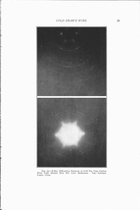
A similar investigation of the 0.58 per cent carbon wire wasmade by means of X-rays. The results of the examination of thesurface and core of the 0.58 per cent carbon material drawn 41.9 percent reduction indicated a slight amount of preferred orientation.The reflection photographs of the 0.58 per cent carbon wire drawn80.6 per cent reduction are shown in Fig. 26. The surface of thematerial indicates some preferred orientation while the core of thewire exhibits somewhat more preferred orientation than the surface.
Elam (11) reports that various investigators have fOUlid thatthe core of wires have the most perfect fiber-structure and that thetensile strength of the core was higher than that of the outer layersof hard drawn wire.
In extremely cold drawn wire we therefore have a condition inwhich the orientation of the wire is variable over the cross section.If the tensile strength of the core of highly drawn wire is greaterthan the outer layers the reason for the lowering of the fatigue ratiomay be explained. The tensile strength is the average strength ofthe material over the entire cross section of the wire. The bendingfatigue limit stress is largely influenced by the characteristics of 'thematerial at the surface of the wire since the maximum bendingstresses occur at the surface. If the surface of the wire is not asstrong as the core a drop in the fatigue ratio is therefore to be expected. This condition is similar to that in which the surface of thewire is decarburized.
A drop in the fatigue ratio does not necessa~ily mean that thewire has been actually damaged by wire drawing as far as fatigue isconcerned, since no internal cracks or fissures were visible. Asshown in Fig. 14 the fatigue limit stress increases with wire drawingup to 90 per cent reduction which is as far as this study has investigated. However, in the latter stages of cold working the fatiguelimit stress does not increase in proportion to the tensile strength.
The bend test results as shown in Fig. 22 indicate that whenwire has been severely cold drawn it is not able to withstand highlylocalized stresses which cause plastic deformation as well as wire
COLD DRAWN WIRE
Fig. 26--X-Ray Diffraction Patterns of 0.58 Per Cent CarbonWire Cold Drawn 80.6 Per Cent Reduction. Top-Surface.Lower-Core.
29

30 H. J. GODFREY
drawn to an intermediate amount of cold drawing. It is for thisreason that the bend test as carried out in this investigation, mightbe used as an index to determine the amount of cold drawing mostadvisable for a given service. Wire should not be cold drawn to amaximum and then be expected to undergo plastic deformation inservice without danger of an early breakdown. However, all featuresof a given problem should be given consideration because relativelyheavy reductions might be most desirable in order to provide physicalcharacteristics essential to satisfactory performance under specialservice conditions.
The work on the fatigue properties of steel wire is being continued at the Fritz Engineering Laboratory. The next investigationwill include a study on the effect of the rate of drafting on theproperties of steel wire.
CONCLUSIONS
1. The characteristics of the fatigue test results on steel wireare influenced by the carbon content of the material. The fatiguelimit of a low carbon material should be determined by a fatiguetest of at least 10,000,000 cycles in duration. For higher carbonmaterials, the length of the test may be considerably less.
2. Normal cold working by means of wire drawing increasesthe fatigue limit of steel wire in proportion to the tensile strength ofthe wire. However, after the cold working exceeds a critical amount,the ratio between the fatigue limit and the tensile strength decreases.
3. The ratio between the fatigue limit and the tensile strengthdecreases with an increase in carbon content, for materials free fromdecarburization.
4. Improving the surface of wire by polishing, increases thefatigue properties of wire.
S. Decarburization on the surface of cold drawn wire reducesthe fatigue properties of wire. The depth of decarburization doesnot seem to have any effect on the fatigue ratio.
6. An electro-galvanized coating does not lower the fatigueratio of a decarburized wire.
7. The bending fatigue properties of cold drawn hot-galvanizedbridge wire may be approximately the same as a heat treated hotgalvanized bridge wire.
8. The bending properties of patented steel wire increase with

COLD DRAWN WIRE 31
I~
cold work up to a critical amount. Beyond this point the bendingproperties decrease.
9. The true bending properties of steel wire may be determined by controlling the severity of the bend test.
10. Both the bending fatigue test and bend test may be included in the several factors which should be considered in decidingupon the desired amount of cold drawing.
11. The effect of wire drawing on the internal structure ofmetallic crystals as shown by X-ray photographs is such that theindividual crystals tend to orient themselves into one position. Theamount of orientation is more apparent when cold working is excessive. The maximum amount of orientation takes place in the coreof the wire.
ACKNOWLEDGMENT
The author wishes to express his appreciation to C. W. Meyersof the American Steel and \\Tire Company and to L. H. Winkler ofthe Bethlehem Steel Company for the material used in this investigation and for their suggestions and advice; to J. N. Kenyon of Columbia University for checking the accuracy of the wire fatigue machineused in this study and to B. K. Daubenspeck, Research Fellow inChemistry at Lehigh University for the X-ray photographs includedin this paper. To the Fritz Engineering Laboratory Staff which includes Professor Hale Sutherland, Director and Professor BruceJohnston, Assistant Director, we express our sincere thanks for theco-operation received in carrying out this investigation. To Professor Inge Lyse, formerly in charge of the Fritz Engineering Laboratory and now at the Norges Tekniske Hoiskole, we express our sincere appreciation for making this investigation possible.
Bibliography
1. Maurice Bonzel, "Steel Wire," 1935, p. 212, Camelot Press.2. H. F. Moore, "Stress, Strain and Structural Damage," Proceedillgs.
American Society for Testing Materials, Vol. 39, Part II, 1939, p. 569.3. Von Ewald, Buschmann, "Das Biege-Zug-Verfahren," Zeit. fiir ~Metal/
k1ll1de, Vol. 26, N 12, December 1934.4. G. Sachs and H. Sieglerschmidt, "Priifung von Seildriihten durch Zug und
Biegeversuche," 111itteiiullgell del' deutschell 111ateriaipriifullgsanstalten,Sonderheft X 1930.
5. E. T. Gill and R. Goodacre, "Some Aspects of the Fatigue Properties ofPatented Steel Wire," Journal, Iron and Steel Institute, Vol. CXXX,No. II, 1934, p. 323.

32 H. J. GODFREY
6. H. J. Gough, "The Fatigue of Metals," Ernest Benn Limited, London,1926, p. 155.
7. E. T. Gill and R. Goodacre, Loc. Cit., p. 304.8. S. M. Shelton and W. H. Swanger, "Fatigue Properties of Steel Wire,"
Journal of Research, National Bureau of Standards, Vol. 14, January1935, p. 21.
9. Maurice Bonzel, Loc. Cit., p. 213.10. C. F. Elam, "Distortion of Metal Crystals," Clarendon Press, Oxford,
1935, p. 56.11. C. F. Elam, Loc. Cit., p. 128.
TIlE AUTIlOR
H. J. GODFREY
HOWARD J. GODFREY has been engineer of tests at theFritz Engineering Laboratory from 1937 to date. He received his B.S. in Ci"il Engineering at Tufts College,1931; M.S. in Civil Engineering at Lehigh University,1933. From 1934 to 1937 he was research engineer atJaIm A. Roebling Sons Co.
IJ