99812794; catalogue special communication...kathrein’s remote electrical tilt system (ret)...
TRANSCRIPT

Antennas and Solutions for Blue Light and Armed Forces
C A T A L O G U E
Special Communication SPECIALCOMMUNICATION

Who we are and what we stand forKathrein is a leading international specialist for
reliable, high-quality communication technologies.
We are an innovation and technology leader in today's
connected world. Our ability to provide solutions and
systems enables people all over the world to communicate,
access information and use media, whether at home, at
the office or on the road.
We cover a broad spectrum: from mobile communication,
RFID and special solutions, to satellite reception and
broadcast technology, to transmission and reception
systems in vehicles.
As a hidden champion and family-owned enterprise, we
have been working on the technologies of tomorrow since
1919. We take pride in our dedicated employees and our
passion for customers and quality.
Our Solutions
Find out more about us at www.kathrein.com
MOBILE COMMUNICATION
BUSINESSSOLUTIONS SAT SPECIAL
COMMUNICATION BROADCAST AUTOMOTIVE
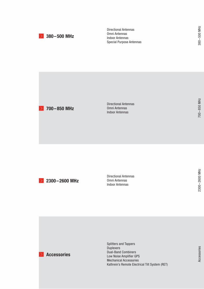
380–500 MHzDirectional AntennasOmni AntennasIndoor AntennasSpecial Purpose Antennas
380
–50
0 M
Hz
700–850 MHzDirectional AntennasOmni AntennasIndoor Antennas
700
–85
0 M
Hz
2300–2600 MHzDirectional AntennasOmni AntennasIndoor Antennas
2300
–26
00 M
Hz
Accessories
Splitters and TappersDuplexersDual-Band CombinersLow Noise Amplifier GPSMechanical AccessoriesKathrein’s Remote Electrical Tilt System (RET)
Acce
ssor
ies

4
5
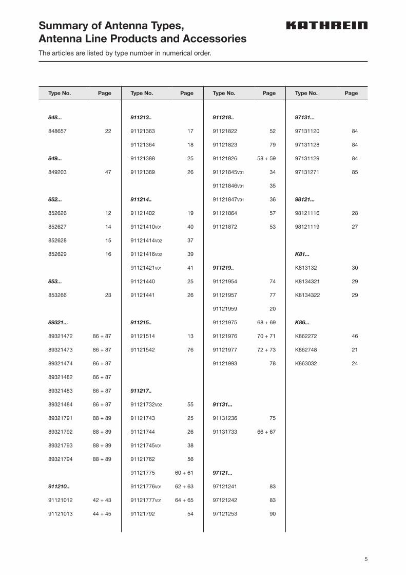
Summary of Antenna Types, Antenna Line Products and AccessoriesThe articles are listed by type number in numerical order.
Type No. PageType No. PageType No. PageType No. Page
848...
848657 22
849...
849203 47
852...
852626 12
852627 14
852628 15
852629 16
853...
853266 23
89321...
89321472 86 + 87
89321473 86 + 87
89321474 86 + 87
89321482 86 + 87
89321483 86 + 87
89321484 86 + 87
89321791 88 + 89
89321792 88 + 89
89321793 88 + 89
89321794 88 + 89
911210..
91121012 42 + 43
91121013 44 + 45
911218..
91121822 52
91121823 79
91121826 58 + 59
91121845V01 34
91121846V01 35
91121847V01 36
91121864 57
91121872 53
911219..
91121954 74
91121957 77
91121959 20
91121975 68 + 69
91121976 70 + 71
91121977 72 + 73
91121993 78
91131...
91131236 75
91131733 66 + 67
97121...
97121241 83
97121242 83
97121253 90
911213..
91121363 17
91121364 18
91121388 25
91121389 26
911214..
91121402 19
91121410V01 40
91121414V02 37
91121416V02 39
91121421V01 41
91121440 25
91121441 26
911215..
91121514 13
91121542 76
911217..
91121732V02 55
91121743 25
91121744 26
91121745V01 38
91121762 56
91121775 60 + 61
91121776V01 62 + 63
91121777V01 64 + 65
91121792 54
97131...
97131120 84
97131128 84
97131129 84
97131271 85
98121...
98121116 28
98121119 27
K81...
K813132 30
K8134321 29
K8134322 29
K86...
K862272 46
K862748 21
K863032 24

6
Antenna Designs:Antenna Families / RET-systemDistinguishing features
Design Compact size and elegant design are the distinguishing features of Kathrein’s antenna families.
Radome The radomes cover the internal antenna components. The fiberglass material guarantees optimum performance with regards to stability, strength, UV resis-tance, painting and weather protection. The colour of the radome of outdoor panel antennas is similar to RAL 7035.
Environmental influences Kathrein antenna designs are based on fundamental engineering knowledge and also on our decades of practical experience, during which the various constructions and materials used have proved their outstanding reliability.
Environmental conditions Kathrein cellular antennas are designed to operate under the environmental conditions as described in ETS 300 019-1-4 class 4.1 E.The antennas exceed this standard with regards to the following items:– Low temperature: –55 °C– High temperature (dry): +60 °C
Environmental tests Kathrein antennas are designed according to the specifications as defined in ETS 300 019-2-4. The homogenous design of Kathreins antenna families uses identical modules and materials. Extensive tests have been performed on typical samples and modules. The vibration test has been adapted relating to frequency and acceleration to the conditions of mast mounted antennas.
Impedance Standard Impedance for all products is 50 Ω unless otherwise stated.
Great variety of half-power beam width, gain values, electrical downtilt
According to the antenna type selected, customers can choose from different half-power beam widths, gain values and electrical downtilts for panel antennas. Downtilts are either fixed or adjustable and controlled by remote electrical tilt system (RET).
Low intermodulationproducts (typ. <–153 dBc)
With many years of experience in the construction of antennas and intensive research into the effects of intermodulation, we offer optimized material and technology used for antennas (the given value refers to 3rd order products measured with 2 carriers of 20 W each).
Excellent tracking Tracking states the symmetry between the +45° and –45° polarized horizontal pattern. Bad tracking values lead to interferences in the network and reduced diversity performance. Kathreins special Tracking compensa tion reduces the average value measured at ±60° to < 2–3 dB.
7
Antenna Designs:Antenna Families / RET-systemDistinguishing features
Multi-array design Besides standard single array antennas, Kathrein designs antennas providing multiple antenna arrays in one radome. These multi-array antennas do not only supply a future-proof multiplicity of diverse frequency bands for various technologies, but are also well-prepared for different MIMO-applications. The Kathrein portfolio contains a high variety of design solutions like interleaved and side-by-side antenna types or combinations of both as well as filter realizations.
Excellent grounding The antennas are DC grounded according EN 50083-1.
Multi-functional installation hardware
Depending on the type, the antennas are equipped with up to 2 attachment points. Panels can be wall-mounted without any additional hardware. For mast-mounting, brackets and mechanical downtilt kits are available. To assist the installation technicians in aligning the panels, an azimuth adjustment tool can be supplied (see Mechanical Accessories).
MTBF Statement Traditionally, passive components like antennas cannot be well calculated due to the lack of a sufficient number of components in the MTBF library. Unfortunately, this constraint results in a very inaccurate calculation. Thus, such results are technically questionable and unrealistic.In essence, antennas are made out of mechnical parts that do not show any failure rates. Only available failure rates can be calculated into an MTBF value. Consequently such components cannot be listed in any MTBF library.
Remote Electical Tilt System AISG Compliancy
Kathrein hereby states that RET devices, as far as the functionality and features are described within the AISG / 3GPP standard, are compliant with the standard.
NGMN-P-BASTA All antennas which are measured according to the specifications given in NGMN-P-BASTA White Paper Version 9.6 are clearly marked in the data sheet. Kathrein is changing over more and more data sheets to NGMN-P-BASTA. The latest data sheets can be found on our homepage.
RET RFID Functionality Kathrein‘s latest Remote Control Unit (RCU) is equipped with an internal RFID reader. Most of our antennas are equipped with RFID tags in their spindles. With this, all relevant antenna data can automatically be read out by the RCU.Further information als well as an up-to-date list of the antennas can be found on our homepage. The according data sheets are marked by a RFID sign.
4.3-10 Connectors Partly, Kathrein’s latest mobile communication antennas and antenna line products are equipped with 4.3-10 connectors.The advantages of this connector are:n Reduced dimensions on the bottom plate for more installation spacen Improved PIM stability and performancen Easier installation, lower tightening torque
The universal 4.3-10 jack can be used with 3 different connector types (screw type, push-pull type and hand screw type).
8
Mechanical downtilt For further technical information please see “Mechanical Accessories”, page 90.
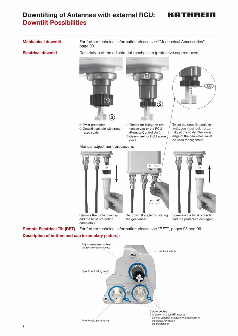
Electrical downtilt Description of the adjustment mechanism (protective cap removed):
Remote Electrical Tilt (RET) For further technical information please see “RET”, pages 95 and 96.
Description of bottom end cap (exemplary picture):
Downtilting of Antennas with external RCU:Downtilt Possibilities
Manual adjustment procedure:
936.
4037
S
ubje
ct to
alte
ratio
n.
Page 2 of 2
KATHREIN-Werke KG . Anton-Kathrein-Straße 1 – 3 . P.O. Box 10 04 44 . 83004 Rosenheim . Germany . Phone +49 8031 184-0 . Fax +49 8031 184-973Internet: www.kathrein.de
General Instructions for Feederline Installationfor Dual-band Antennas
Please note: In order not to damage the interfaces, please make sure that only the right tools are used.Tighten the feederline connector interfaces solely by using a common torque-wrench with a suitable wrenchwidth.
Installation of the feederline connector and RCU (optional):In order to protect the adjustment mechanism the protective caps have to be attached during feederline installation!
Carefully place the connector and fix thenut using a torque-wrench (according tothe manufacturers guidelines).
After feederline installation the optionalremote control units (RCU) can bemounted.
For a full description of RCU installationplease refer to the respective data sheet.
Ventilation hole
Colour coding:Correlation of each RF input to:– the corresponding adjustment mechanism– the frequency range– the polarization
Adjustment mechanism(protective cap removed)
7-16 female (long neck)
Spindle with tilting scale
Description of bottom end cap (exemplary picture):
Remove the protective cap and the twist protection completely.
➀ Twist protection.➁ Downtilt spindle with integ-
rated scale.
➀ Thread for fixing the pro-tective cap or the RCU (Remote Control Unit).
➁ Gearwheel for RCU power drive.
To set the downtilt angle ex-actly, you must look horizon-tally at the scale. The lower edge of the gear wheel must be used for alignment.
Set downtilt angle by rotating the gearwheel.
Screw on the twist protection and the protective cap again.
0° – max.°
0° – max.°
1
2
2
1
9
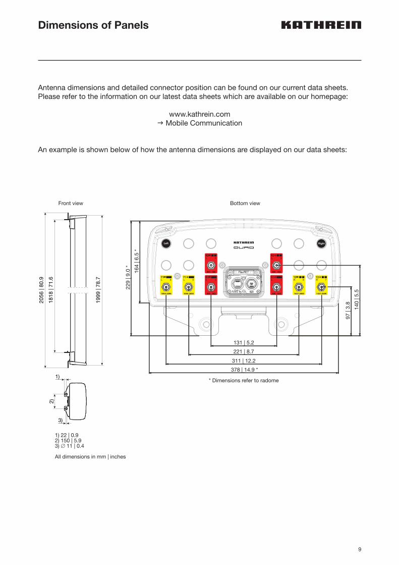
Dimensions of Panels
Antenna dimensions and detailed connector position can be found on our current data sheets. Please refer to the information on our latest data sheets which are available on our homepage:
www.kathrein.comg Mobile Communication
An example is shown below of how the antenna dimensions are displayed on our data sheets:
1818
| 71
.62)
1)
2056
| 80
.9
1999
| 78
.7
3)
1) 22 | 0.92) 150 | 5.93) ∅ 11 | 0.4 All dimensions in mm | inches
97
| 3.8
140
| 5.
5 229
| 9.
0 *
131 | 5.2
221 | 8.7
311 | 12.2
164
| 6.
5 *
378 | 14.9 *
L 6
1695-2690
Y1 Y1L 5
1695-2690
L 2
698 - 862
R1
L 4
880 - 960
R2L 3
880 - 960
R2
L 1
698 - 862
R1R 8
1427-2690
Y2R 7
1427-2690
Y2
* Dimensions refer to radome
Bottom viewFront view
10
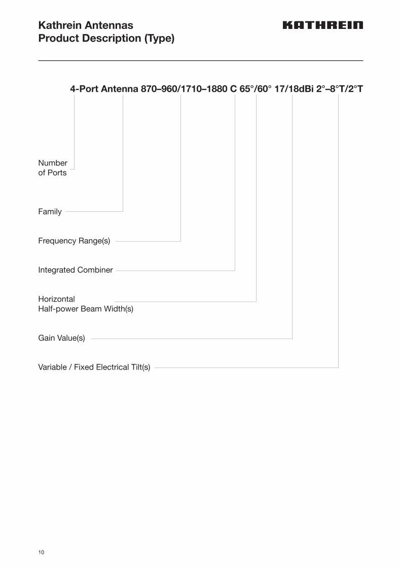
Kathrein AntennasProduct Description (Type)
4-Port Antenna 870–960/1710–1880 C 65°/60° 17/18dBi 2°–8°T/2°T
Numberof Ports
Family
Frequency Range(s)
Integrated Combiner
HorizontalHalf-power Beam Width(s)
Gain Value(s)
Variable / Fixed Electrical Tilt(s)
11
380
–50
0 M
Hz
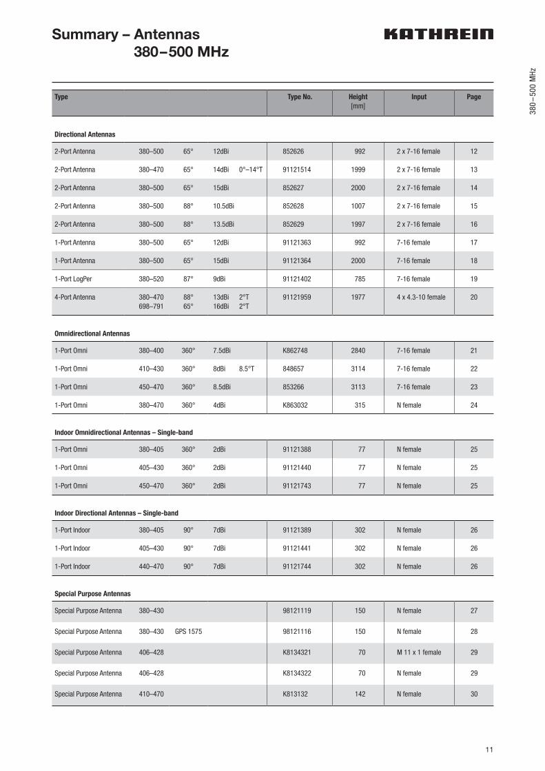
Type Type No. Height[mm]
Input Page
Directional Antennas
2-Port Antenna 380–500 65° 12dBi 852626 992 2 x 7-16 female 12
2-Port Antenna 380–470 65° 14dBi 0°–14°T 91121514 1999 2 x 7-16 female 13
2-Port Antenna 380–500 65° 15dBi 852627 2000 2 x 7-16 female 14
2-Port Antenna 380–500 88° 10.5dBi 852628 1007 2 x 7-16 female 15
2-Port Antenna 380–500 88° 13.5dBi 852629 1997 2 x 7-16 female 16
1-Port Antenna 380–500 65° 12dBi 91121363 992 7-16 female 17
1-Port Antenna 380–500 65° 15dBi 91121364 2000 7-16 female 18
1-Port LogPer 380–520 87° 9dBi 91121402 785 7-16 female 19
4-Port Antenna 380–470698–791
88°65°
13dBi 2°T16dBi 2°T
91121959 1977 4 x 4.3-10 female 20
Omnidirectional Antennas
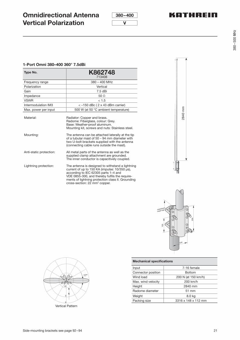
1-Port Omni 380–400 360° 7.5dBi K862748 2840 7-16 female 21
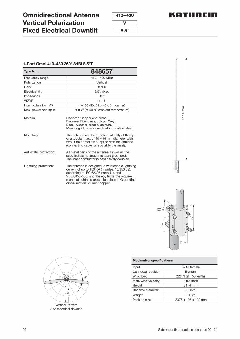
1-Port Omni 410–430 360° 8dBi 8.5°T 848657 3114 7-16 female 22
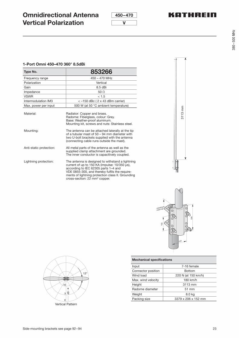
1-Port Omni 450–470 360° 8.5dBi 853266 3113 7-16 female 23
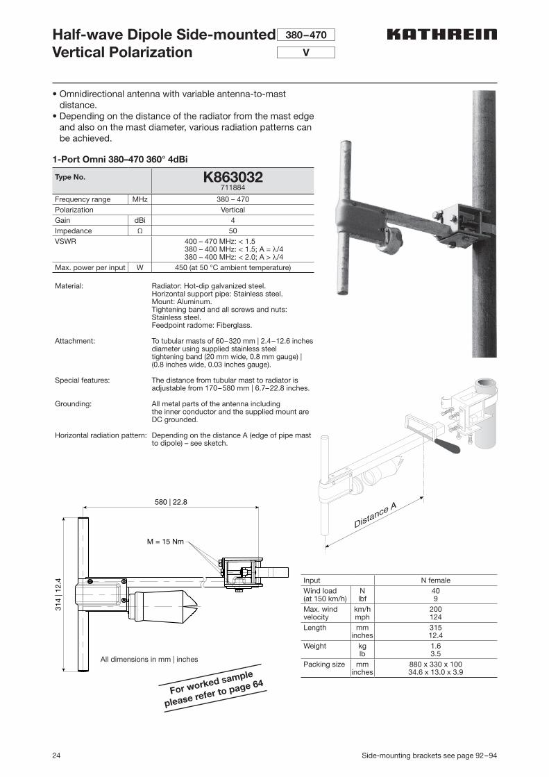
1-Port Omni 380–470 360° 4dBi K863032 315 N female 24
Indoor Omnidirectional Antennas – Single-band
1-Port Omni 380–405 360° 2dBi 91121388 77 N female 25
1-Port Omni 405–430 360° 2dBi 91121440 77 N female 25
1-Port Omni 450–470 360° 2dBi 91121743 77 N female 25
Indoor Directional Antennas – Single-band
1-Port Indoor 380–405 90° 7dBi 91121389 302 N female 26
1-Port Indoor 405–430 90° 7dBi 91121441 302 N female 26
1-Port Indoor 440–470 90° 7dBi 91121744 302 N female 26
Special Purpose Antennas
Special Purpose Antenna 380–430 98121119 150 N female 27
Special Purpose Antenna 380–430 GPS 1575 98121116 150 N female 28
Special Purpose Antenna 406–428 K8134321 70 M 11 x 1 female 29
Special Purpose Antenna 406–428 K8134322 70 N female 29
Special Purpose Antenna 410–470 K813132 142 N female 30
Summary – Antennas 380–500 MHz
12 For more information about additional mounting accessories please refer to page 91
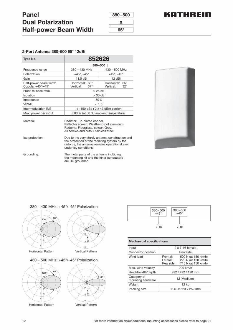
PanelDual PolarizationHalf-power Beam Width
380–500
X
65°
2-Port Antenna 380–500 65° 12dBi
Type No. 852626
Frequency range 380 – 430 MHz 430 – 500 MHzPolarization +45°, –45° +45°, –45°Gain 11.5 dBi 12 dBiHalf-power beam widthCopolar +45°/–45°
Horizontal: 68°Vertical: 37°
Horizontal: 65°Vertical: 32°
Front-to-back ratio > 25 dBIsolation > 30 dBImpedance 50 ΩVSWR < 1.5Intermodulation IM3 < –150 dBc ( 2 x 43 dBm carrier)Max. power per input 500 W (at 50 °C ambient temperature)
Material: Radiator: Tin-plated copper. Reflector screen: Weather-proof aluminum.Radome: Fiberglass, colour: Grey.All screws and nuts: Stainless steel.
Ice protection: Due to the very sturdy antenna construction and the protection of the radiating system by the radome, the antenna remains operational even under icy conditions.
Grounding: The metal parts of the antenna including the mounting kit and the inner conductors are DC grounded.
380–500
Mechanical specifications
Input 2 x 7-16 femaleConnector position RearsideWind load Frontal: 500 N (at 150 km/h)
Lateral: 220 N (at 150 km/h)Rearside: 715 N (at 150 km/h)
Max. wind velocity 200 km/hHeight/width/depth 992 / 492 / 190 mmCategory ofmounting hardware M (Medium)
Weight 12 kgPacking size 1140 x 523 x 252 mm
380 – 430 MHz: +45°/–45° Polarization
430 – 500 MHz: +45°/–45° Polarization
10
3
0
68°136°
Bd 3 dB
0
37°
10
10
3
0
65°122°
Bd 3 dB
0
32°
10
Horizontal Pattern
Horizontal Pattern
Vertical Pattern
Vertical Pattern
380–500–45°
380–500+45°
7-16 7-16
13For more information about additional mounting accessories please refer to page 91
2 Po
rts
Mechanical specifications
Input 2 x 7-16 femaleConnector position BottomAdjustmentmechanism
1 x, Position bottomcontinuously adjustable
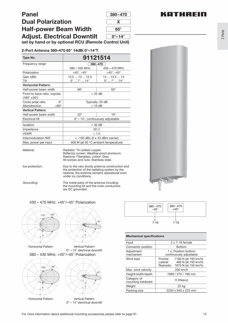
Wind load Frontal: 1160 N (at 150 km/h)Lateral: 480 N (at 150 km/h)Rearside: 1870 N (at 150 km/h)
Max. wind velocity 200 km/hHeight/width/depth 1999 / 575 / 199 mmCategory ofmounting hardware H (Heavy)
Weight 22 kgPacking size 2250 x 640 x 225 mm
PanelDual PolarizationHalf-power Beam WidthAdjust. Electrical Downtiltset by hand or by optional RCU (Remote Control Unit)
380–470
X
65°
Horizontal Pattern
Horizontal Pattern
Vertical Pattern0° – 14° electrical downtilt
Vertical Pattern0° – 14° electrical downtilt
2-Port Antenna 380–470 65° 14dBi 0°–14°T
Type No. 91121514Frequency range
380 – 430 MHz 430 – 470 MHzPolarization +45°, –45° +45°, –45°Gain (dBi)Tilt
13.5 ... 13 ... 12.50° ... 7° ... 14°
14 ... 13.5 ... 130° ... 7° ... 14°
Horizontal Pattern:Half-power beam width 66° 62°Front-to-back ratio, copolar(180° ±30°)
> 25 dB
Cross polar ratio 0°Maindirection ±60°
Typically: 25 dB> 10 dB
Vertical Pattern:Half-power beam width 22° 19°Electrical tilt 0° – 14°, continuously adjustable
Isolation > 30 dBImpedance 50 ΩVSWR < 1.5Intermodulation IM3 < –150 dBc (2 x 43 dBm carrier)Max. power per input 400 W (at 50 °C ambient temperature)
Material: Radiator: Tin-plated copper. Reflector screen: Weather-proof aluminum.Radome: Fiberglass, colour: Grey.All screws and nuts: Stainless steel.
Ice protection: Due to the very sturdy antenna construction and the protection of the radiating system by the radome, the antenna remains operational even under icy conditions.
Grounding: The metal parts of the antenna including the mounting kit and the inner conductors are DC grounded.
430 – 470 MHz: +45°/–45° Polarization
380 – 430 MHz: +45°/–45° Polarization
380–470
0°–14°
62°115°
dB
10
3
0
10
3
0
19°
dB
122°
dB
10
3
0
66°
3
0
10
dB
22°
380–470–45°
380–470+45°
7-16 7-16
14 For more information about additional mounting accessories please refer to page 91
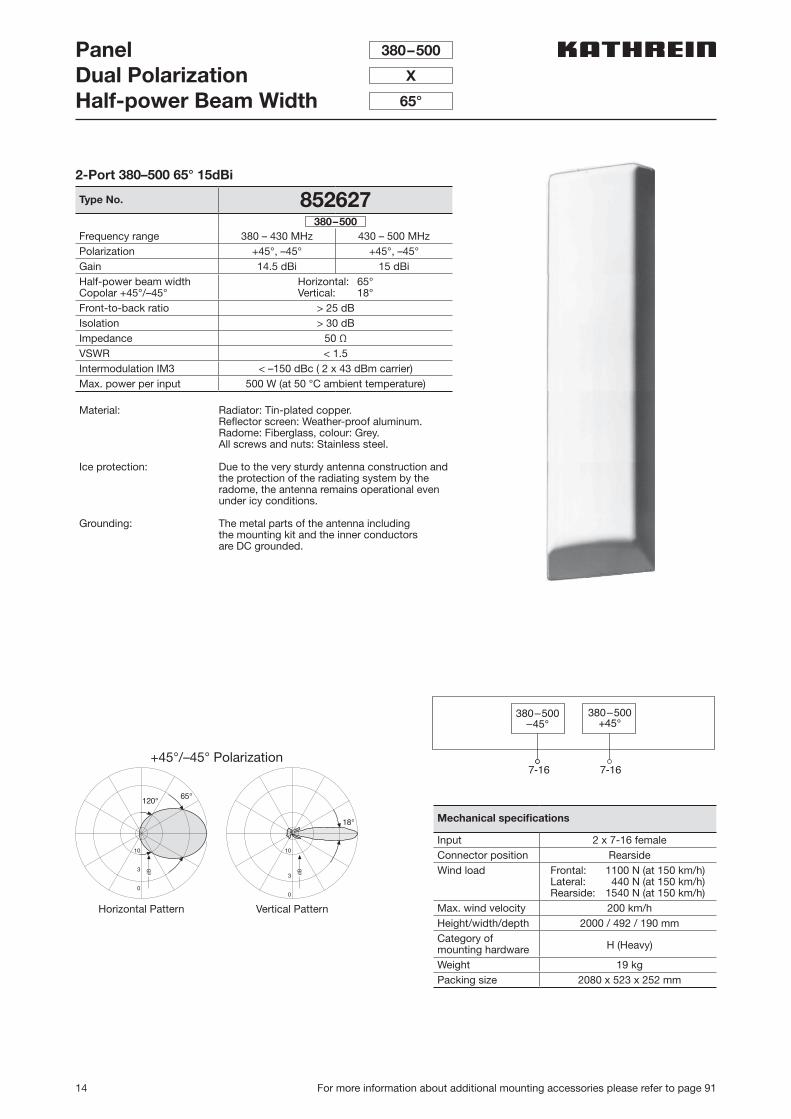
PanelDual PolarizationHalf-power Beam Width
380–500
X
65°
2-Port 380–500 65° 15dBi
Type No. 852627
Frequency range 380 – 430 MHz 430 – 500 MHzPolarization +45°, –45° +45°, –45°Gain 14.5 dBi 15 dBiHalf-power beam widthCopolar +45°/–45°
Horizontal: 65°Vertical: 18°
Front-to-back ratio > 25 dBIsolation > 30 dBImpedance 50 ΩVSWR < 1.5Intermodulation IM3 < –150 dBc ( 2 x 43 dBm carrier)Max. power per input 500 W (at 50 °C ambient temperature)
Material: Radiator: Tin-plated copper. Reflector screen: Weather-proof aluminum.Radome: Fiberglass, colour: Grey.All screws and nuts: Stainless steel.
Ice protection: Due to the very sturdy antenna construction and the protection of the radiating system by the radome, the antenna remains operational even under icy conditions.
Grounding: The metal parts of the antenna including the mounting kit and the inner conductors are DC grounded.
380–500
Mechanical specifications
Input 2 x 7-16 femaleConnector position RearsideWind load Frontal: 1100 N (at 150 km/h)
Lateral: 440 N (at 150 km/h)Rearside: 1540 N (at 150 km/h)
Max. wind velocity 200 km/hHeight/width/depth 2000 / 492 / 190 mmCategory ofmounting hardware H (Heavy)
Weight 19 kgPacking size 2080 x 523 x 252 mm
+45°/–45° Polarization
10
3
0
65°120°
Bd
10
3
0
18°
Bd
Horizontal Pattern Vertical Pattern
380–500–45°
380–500+45°
7-16 7-16
15
380
–50
0 M
Hz
For more information about additional mounting accessories please refer to page 91
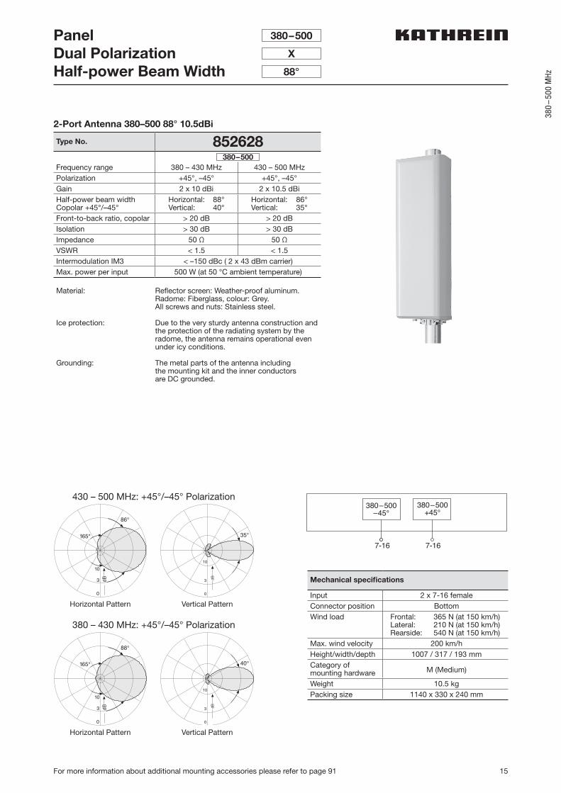
PanelDual PolarizationHalf-power Beam Width
380–500
X
88°
2-Port Antenna 380–500 88° 10.5dBi
Type No. 852628
Frequency range 380 – 430 MHz 430 – 500 MHzPolarization +45°, –45° +45°, –45°Gain 2 x 10 dBi 2 x 10.5 dBiHalf-power beam widthCopolar +45°/–45°
Horizontal: 88°Vertical: 40°
Horizontal: 86°Vertical: 35°
Front-to-back ratio, copolar > 20 dB > 20 dBIsolation > 30 dB > 30 dBImpedance 50 Ω 50 ΩVSWR < 1.5 < 1.5Intermodulation IM3 < –150 dBc ( 2 x 43 dBm carrier)Max. power per input 500 W (at 50 °C ambient temperature)
Material: Reflector screen: Weather-proof aluminum.Radome: Fiberglass, colour: Grey.All screws and nuts: Stainless steel.
Ice protection: Due to the very sturdy antenna construction and the protection of the radiating system by the radome, the antenna remains operational even under icy conditions.
Grounding: The metal parts of the antenna including the mounting kit and the inner conductors are DC grounded.
380–500
Mechanical specifications
Input 2 x 7-16 femaleConnector position BottomWind load Frontal: 365 N (at 150 km/h)
Lateral: 210 N (at 150 km/h)Rearside: 540 N (at 150 km/h)
Max. wind velocity 200 km/hHeight/width/depth 1007 / 317 / 193 mmCategory ofmounting hardware M (Medium)
Weight 10.5 kgPacking size 1140 x 330 x 240 mm
380–500–45°
380–500+45°
7-16 7-16
430 – 500 MHz: +45°/–45° Polarization
380 – 430 MHz: +45°/–45° Polarization
3 dB
10
0
86°
165°
3
0
10
Bd
35°
3 dB
10
0
88°
165°
3
0
10
Bd
40°
Horizontal Pattern
Horizontal Pattern
Vertical Pattern
Vertical Pattern
16 For more information about additional mounting accessories please refer to page 91
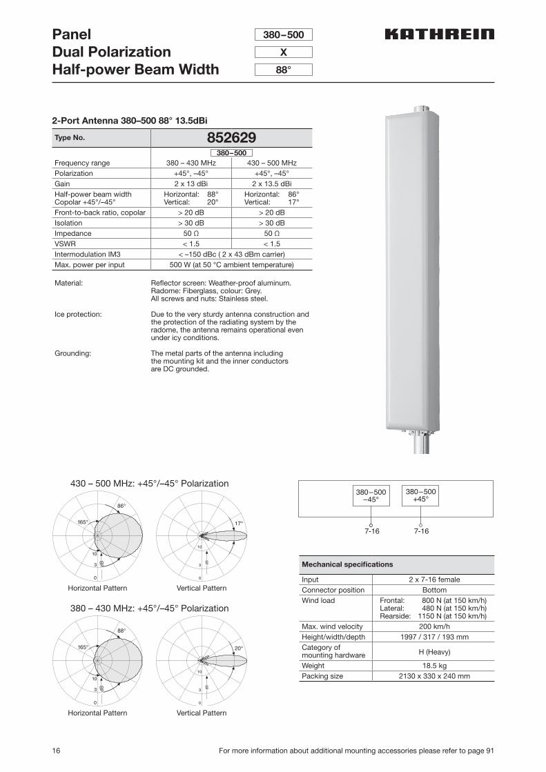
PanelDual PolarizationHalf-power Beam Width
380–500
X
88°
2-Port Antenna 380–500 88° 13.5dBi
Type No. 852629
Frequency range 380 – 430 MHz 430 – 500 MHzPolarization +45°, –45° +45°, –45°Gain 2 x 13 dBi 2 x 13.5 dBiHalf-power beam widthCopolar +45°/–45°
Horizontal: 88°Vertical: 20°
Horizontal: 86°Vertical: 17°
Front-to-back ratio, copolar > 20 dB > 20 dBIsolation > 30 dB > 30 dBImpedance 50 Ω 50 ΩVSWR < 1.5 < 1.5Intermodulation IM3 < –150 dBc ( 2 x 43 dBm carrier)Max. power per input 500 W (at 50 °C ambient temperature)
Material: Reflector screen: Weather-proof aluminum.Radome: Fiberglass, colour: Grey.All screws and nuts: Stainless steel.
Ice protection: Due to the very sturdy antenna construction and the protection of the radiating system by the radome, the antenna remains operational even under icy conditions.
Grounding: The metal parts of the antenna including the mounting kit and the inner conductors are DC grounded.
380–500
Mechanical specifications
Input 2 x 7-16 femaleConnector position BottomWind load Frontal: 800 N (at 150 km/h)
Lateral: 480 N (at 150 km/h)Rearside: 1150 N (at 150 km/h)
Max. wind velocity 200 km/hHeight/width/depth 1997 / 317 / 193 mmCategory ofmounting hardware H (Heavy)
Weight 18.5 kgPacking size 2130 x 330 x 240 mm
380–500–45°
380–500+45°
7-16 7-16
430 – 500 MHz: +45°/–45° Polarization
380 – 430 MHz: +45°/–45° Polarization
3 dB
10
0
86°
165°
3
0
10
Bd
17°
3 dB
10
0
88°
165°
3
0
10
Bd
20°
Horizontal Pattern
Horizontal Pattern
Vertical Pattern
Vertical Pattern
17
380
–50
0 M
Hz
For more information about additional mounting accessories please refer to page 91
Multi-band PanelVertical PolarizationHalf-power Beam Width
380–500
V
65°
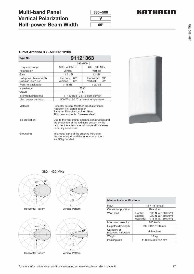
1-Port Antenna 380–500 65° 12dBi
Type No. 91121363
Frequency range 380 – 430 MHz 430 – 500 MHzPolarization Vertical VerticalGain 11.5 dBi 12 dBiHalf-power beam widthCopolar +45°/–45°
Horizontal: 68°Vertical: 37°
Horizontal: 63°Vertical: 32°
Front-to-back ratio > 18 dB > 20 dBImpedance 50 ΩVSWR < 1.5Intermodulation IM3 < –150 dBc ( 2 x 43 dBm carrier)Max. power per input 500 W (at 50 °C ambient temperature)
Material: Reflector screen: Weather-proof aluminum. Radiator: Tin-plated copper.Radome: Fiberglass, colour: Grey.All screws and nuts: Stainless steel.
Ice protection: Due to the very sturdy antenna construction and the protection of the radiating system by the radome, the antenna remains operational even under icy conditions.
Grounding: The metal parts of the antenna including the mounting kit and the inner conductors are DC grounded.
380–500
Mechanical specifications
Input 1 x 7-16 femaleConnector position RearsideWind load Frontal: 500 N (at 150 km/h)
Lateral: 220 N (at 150 km/h)Rearside: 715 N (at 150 km/h)
Max. wind velocity 200 km/hHeight/width/depth 992 / 492 / 190 mmCategory ofmounting hardware M (Medium)
Weight 12 kgPacking size 1140 x 523 x 252 mm
380 – 430 MHz
10
3
0
68°136°
Bd 3 dB
0
37°
10
10
3
0
63°122°
Bd 3 dB
0
32°
10
Horizontal Pattern
Horizontal Pattern
Vertical Pattern
Vertical Pattern
18 For more information about additional mounting accessories please refer to page 91
Multi-band PanelVertical PolarizationHalf-power Beam Width
380–500
V
65°
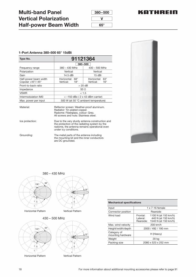
1-Port Antenna 380–500 65° 15dBi
Type No. 91121364
Frequency range 380 – 430 MHz 430 – 500 MHzPolarization Vertical VerticalGain 14.5 dBi 15 dBiHalf-power beam widthCopolar +45°/–45°
Horizontal: 68°Vertical: 18°
Horizontal: 63°Vertical: 16°
Front-to-back ratio > 20 dBImpedance 50 ΩVSWR < 1.5Intermodulation IM3 < –150 dBc ( 2 x 43 dBm carrier)Max. power per input 500 W (at 50 °C ambient temperature)
Material: Reflector screen: Weather-proof aluminum. Radiator: Tin-plated copper.Radome: Fiberglass, colour: Grey.All screws and nuts: Stainless steel.
Ice protection: Due to the very sturdy antenna construction and the protection of the radiating system by the radome, the antenna remains operational even under icy conditions.
Grounding: The metal parts of the antenna including the mounting kit and the inner conductors are DC grounded.
380–500
Mechanical specifications
Input 1 x 7-16 femaleConnector position RearsideWind load Frontal: 1100 N (at 150 km/h)
Lateral: 440 N (at 150 km/h)Rearside: 1540 N (at 150 km/h)
Max. wind velocity 200 km/hHeight/width/depth 2000 / 492 / 190 mmCategory ofmounting hardware H (Heavy)
Weight 20 kgPacking size 2080 x 523 x 252 mm
380 – 430 MHz
430 – 500 MHz
10
3
0
68°136°
Bd
10
3
0
18°
Bd
10
3
0
63°122°
Bd
10
3
0
16°
Bd
Horizontal Pattern
Horizontal Pattern
Vertical Pattern
Vertical Pattern
19
380
–50
0 M
Hz
For more information about additional mounting accessories please refer to page 91
Logarithmic-periodicVertical PolarizationHalf-power Beam Width
380–520
V
87°
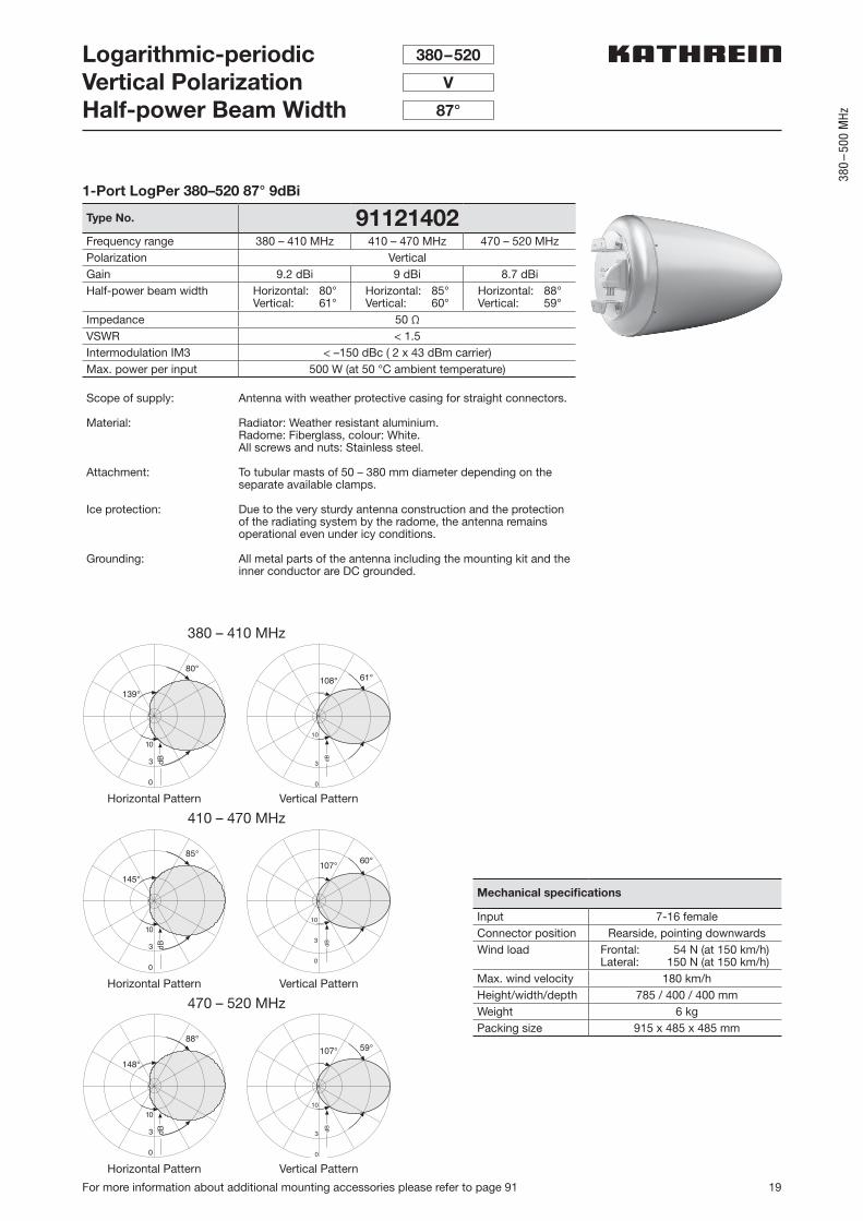
1-Port LogPer 380–520 87° 9dBi
Type No. 91121402Frequency range 380 – 410 MHz 410 – 470 MHz 470 – 520 MHzPolarization VerticalGain 9.2 dBi 9 dBi 8.7 dBiHalf-power beam width Horizontal: 80°
Vertical: 61°Horizontal: 85°Vertical: 60°
Horizontal: 88°Vertical: 59°
Impedance 50 ΩVSWR < 1.5Intermodulation IM3 < –150 dBc ( 2 x 43 dBm carrier)Max. power per input 500 W (at 50 °C ambient temperature)
Scope of supply: Antenna with weather protective casing for straight connectors.
Material: Radiator: Weather resistant aluminium.Radome: Fiberglass, colour: White.All screws and nuts: Stainless steel.
Attachment: To tubular masts of 50 – 380 mm diameter depending on the separate available clamps.
Ice protection: Due to the very sturdy antenna construction and the protection of the radiating system by the radome, the antenna remains operational even under icy conditions.
Grounding: All metal parts of the antenna including the mounting kit and the inner conductor are DC grounded.
Mechanical specifications
Input 7-16 femaleConnector position Rearside, pointing downwardsWind load Frontal: 54 N (at 150 km/h)
Lateral: 150 N (at 150 km/h)Max. wind velocity 180 km/hHeight/width/depth 785 / 400 / 400 mmWeight 6 kgPacking size 915 x 485 x 485 mm
380 – 410 MHz
410 – 470 MHz
470 – 520 MHz
3 dB
10
0
80°
139°108° 61°
3 dB
10
0
85°
145°
3 dB
10
0
88°
148°
10
3
0
60°107°
Bd
107° 59°
Horizontal Pattern
Horizontal Pattern
Horizontal Pattern
Vertical Pattern
Vertical Pattern
Vertical Pattern
20 For more information about additional mounting accessories please refer to page 91
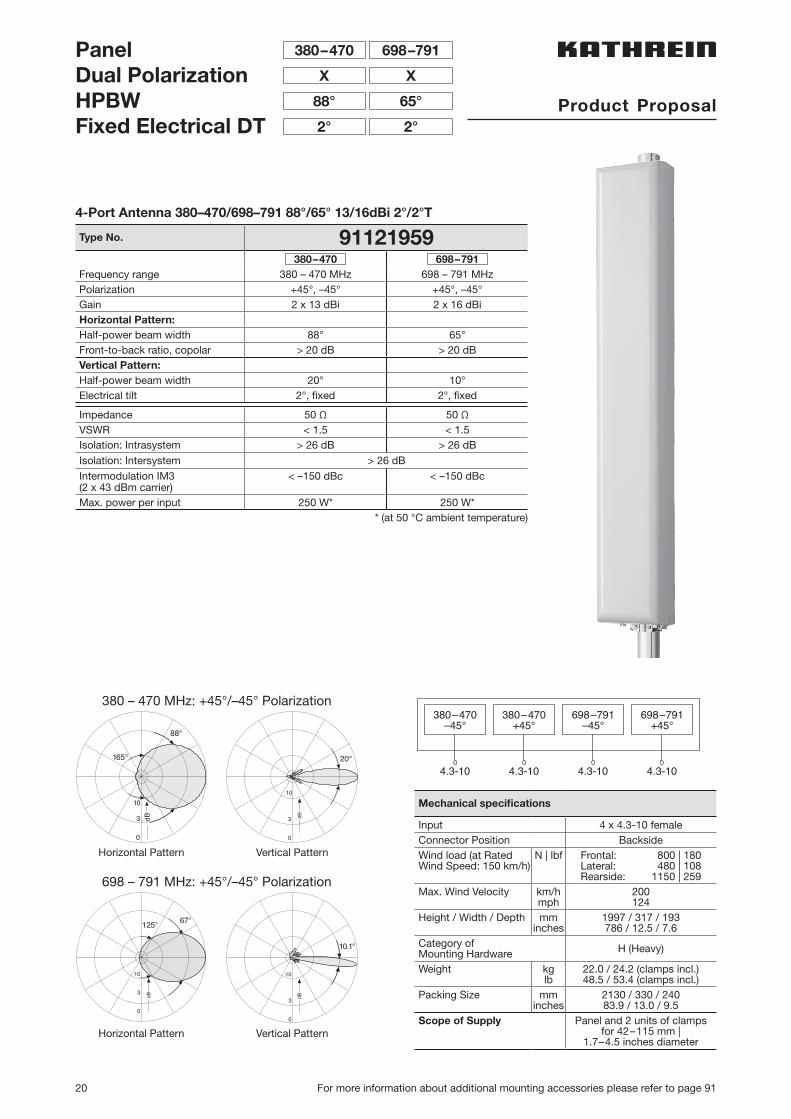
PanelDual PolarizationHPBWFixed Electrical DT
698–791380–470
XX
65°
2°
88°
2°
4.3-10 4.3-10
380–470–45°
380–470+45°
698–791–45°
698–791+45°
4.3-10 4.3-10
380 – 470 MHz: +45°/–45° Polarization
698 – 791 MHz: +45°/–45° Polarization
10
3
0
67°125°
dB
3 dB
10
0
88°
165°
10.1°
Bd
10
3
0
3
0
10
Bd
20°
Horizontal Pattern
Horizontal Pattern
Vertical Pattern
Vertical Pattern
Mechanical specifications
Input 4 x 4.3-10 femaleConnector Position BacksideWind load (at Rated Wind Speed: 150 km/h)
N | lbf Frontal: 800 | 180Lateral: 480 | 108Rearside: 1150 | 259
Max. Wind Velocity km/hmph
200124
Height / Width / Depth mminches
1997 / 317 / 193786 / 12.5 / 7.6
Category of Mounting Hardware H (Heavy)
Weight kglb
22.0 / 24.2 (clamps incl.)48.5 / 53.4 (clamps incl.)
Packing Size mminches
2130 / 330 / 24083.9 / 13.0 / 9.5
Scope of Supply Panel and 2 units of clamps for 42–115 mm |
1.7–4.5 inches diameter
4-Port Antenna 380–470/698–791 88°/65° 13/16dBi 2°/2°T
Type No. 91121959380–470 698–791
Frequency range 380 – 470 MHz 698 – 791 MHzPolarization +45°, –45° +45°, –45°Gain 2 x 13 dBi 2 x 16 dBiHorizontal Pattern:Half-power beam width 88° 65°Front-to-back ratio, copolar > 20 dB > 20 dBVertical Pattern:Half-power beam width 20° 10°Electrical tilt 2°, fixed 2°, fixed
Impedance 50 Ω 50 ΩVSWR < 1.5 < 1.5Isolation: Intrasystem > 26 dB > 26 dB
Isolation: Intersystem > 26 dB
Intermodulation IM3(2 x 43 dBm carrier)
< –150 dBc < –150 dBc
Max. power per input 250 W* 250 W** (at 50 °C ambient temperature)
Product Proposal
21
380
–50
0 M
Hz
Side-mounting brackets see page 92–94
1-Port Omni 380–400 360° 7.5dBi
Type No. K862748713408
Frequency range 380 – 400 MHzPolarization VerticalGain 7.5 dBiImpedance 50 ΩVSWR < 1.5Intermodulation IM3 < –150 dBc ( 2 x 43 dBm carrier)Max. power per input 500 W (at 50 °C ambient temperature)
Material: Radiator: Copper and brass. Radome: Fiberglass, colour: Grey.Base: Weather-proof aluminum. Mounting kit, screws and nuts: Stainless steel.
Mounting: The antenna can be attached laterally at the tip of a tubular mast of 50 – 94 mm diameter with two U-bolt brackets supplied with the antenna (connecting cable runs outside the mast).
Anti-static protection: All metal parts of the antenna as well as the supplied clamp attachment are grounded. The inner conductor is capacitively coupled.
Lightning protection: The antenna is designed to withstand a lightning current of up to 150 KA (impulse: 10/350 µs), according to IEC 62305 parts 1–4 and VDE 0855-300, and thereby fulfils the require-ments of lightning protection class II. Grounding cross-section: 22 mm2 copper.
Omnidirectional AntennaVertical Polarization
380–400
V
1 50
230
104
maximum
mast top
Bd
17°
10
3
0
Vertical Pattern
2840
mm
Mechanical specifications
Input 7-16 femaleConnector position BottomWind load 200 N (at 150 km/h)Max. wind velocity 200 km/hHeight 2840 mmRadome diameter 51 mm
Weight 8.0 kgPacking size 3316 x 148 x 112 mm
22 Side-mounting brackets see page 92–94
Omnidirectional AntennaVertical PolarizationFixed Electrical Downtilt 8.5°
1-Port Omni 410–430 360° 8dBi 8.5°T
Type No. 848657Frequency range 410 – 430 MHzPolarization VerticalGain 8 dBiElectrical tilt 8.5°, fixedImpedance 50 ΩVSWR < 1.5Intermodulation IM3 < –150 dBc ( 2 x 43 dBm carrier)Max. power per input 500 W (at 50 °C ambient temperature)
Material: Radiator: Copper and brass. Radome: Fiberglass, colour: Grey.Base: Weather-proof aluminum. Mounting kit, screws and nuts: Stainless steel.
Mounting: The antenna can be attached laterally at the tip of a tubular mast of 50 – 94 mm diameter with two U-bolt brackets supplied with the antenna (connecting cable runs outside the mast).
Anti-static protection: All metal parts of the antenna as well as the supplied clamp attachment are grounded. The inner conductor is capacitively coupled.
Lightning protection: The antenna is designed to withstand a lightning current of up to 150 KA (impulse: 10/350 µs), according to IEC 62305 parts 1–4 and VDE 0855-300, and thereby fulfils the require-ments of lightning protection class II. Grounding cross-section: 22 mm2 copper.
Vertical Pattern8.5° electrical downtilt
Mechanical specifications
Input 7-16 femaleConnector position BottomWind load 220 N (at 150 km/h)Max. wind velocity 180 km/hHeight 3114 mmRadome diameter 51 mm
Weight 8.0 kgPacking size 3376 x 196 x 102 mm
410–430
V
1 50
230
104
maximum
mast top
3 dB
10
0
14°
3114
mm
23
380
–50
0 M
Hz
Side-mounting brackets see page 92–94
1-Port Omni 450–470 360° 8.5dBi
Type No. 853266Frequency range 450 – 470 MHzPolarization VerticalGain 8.5 dBiImpedance 50 ΩVSWR < 1.5Intermodulation IM3 < –150 dBc ( 2 x 43 dBm carrier)Max. power per input 500 W (at 50 °C ambient temperature)
Material: Radiator: Copper and brass. Radome: Fiberglass, colour: Grey.Base: Weather-proof aluminum. Mounting kit, screws and nuts: Stainless steel.
Mounting: The antenna can be attached laterally at the tip of a tubular mast of 50 – 94 mm diameter with two U-bolt brackets supplied with the antenna (connecting cable runs outside the mast).
Anti-static protection: All metal parts of the antenna as well as the supplied clamp attachment are grounded. The inner conductor is capacitively coupled.
Lightning protection: The antenna is designed to withstand a lightning current of up to 150 KA (impulse: 10/350 µs), according to IEC 62305 parts 1–4 and VDE 0855-300, and thereby fulfils the require-ments of lightning protection class II. Grounding cross-section: 22 mm2 copper.
Omnidirectional AntennaVertical Polarization
450–470
V
1 50
230
104
maximum
mast top
3 dB
10
0
12°
Vertical Pattern
3113
mm
Mechanical specifications
Input 7-16 femaleConnector position BottomWind load 220 N (at 150 km/h)Max. wind velocity 180 km/hHeight 3113 mmRadome diameter 51 mm
Weight 8.0 kgPacking size 3379 x 206 x 152 mm
24 Side-mounting brackets see page 92–94
For worked sample
please refer to page 64
Input N femaleWind load(at 150 km/h)
Nlbf
409
Max. windvelocity
km/hmph
200124
Length mminches
31512.4
Weight kglb
1.63.5
Packing size mminches
880 x 330 x 10034.6 x 13.0 x 3.9
Half-wave Dipole Side-mountedVertical Polarization
1-Port Omni 380–470 360° 4dBi
Type No. K863032711884
Frequency range MHz 380 – 470Polarization VerticalGain dBi 4Impedance Ω 50VSWR 400 – 470 MHz: < 1.5
380 – 400 MHz: < 1.5; A = λ/4380 – 400 MHz: < 2.0; A > λ/4
Max. power per input W 450 (at 50 °C ambient temperature)
Material: Radiator: Hot-dip galvanized steel.Horizontal support pipe: Stainless steel.Mount: Aluminum. Tightening band and all screws and nuts: Stainless steel.Feedpoint radome: Fiberglass.
Attachment: To tubular masts of 60–320 mm | 2.4–12.6 inches diameter using supplied stainless steel tightening band (20 mm wide, 0.8 mm gauge) | (0.8 inches wide, 0.03 inches gauge).
Special features: The distance from tubular mast to radiator is adjustable from 170–580 mm | 6.7–22.8 inches.
Grounding: All metal parts of the antenna including the inner conductor and the supplied mount are DC grounded.
Horizontal radiation pattern: Depending on the distance A (edge of pipe mast to dipole) – see sketch.
380–470
V
• Omnidirectional antenna with variable antenna-to-mast distance.
• Depending on the distance of the radiator from the mast edge and also on the mast diameter, various radiation patterns can be achieved.
Distance A
314
| 12.
4
580 | 22.8
M = 15 Nm
All dimensions in mm | inches
25
380
–50
0 M
Hz
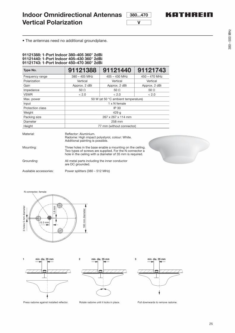
91121388: 1-Port Indoor 380–405 360° 2dBi91121440: 1-Port Indoor 405–430 360° 2dBi91121743: 1-Port Indoor 450–470 360° 2dBi
Type No. 91121388 91121440 91121743Frequency range 380 – 405 MHz 405 – 430 MHz 450 – 470 MHzPolarization Vertical Vertical VerticalGain Approx. 2 dBi Approx. 2 dBi Approx. 2 dBiImpedance 50 Ω 50 Ω 50 ΩVSWR < 2.0 < 2.0 < 2.0Max. power 50 W (at 50 °C ambient temperature)Input 1 x N femaleProtection class IP 30Weight 429 gPacking size 267 x 267 x 114 mmDiameter 258 mmHeight 77 mm (without connector)
Material: Reflector: Aluminium.Radome: High impact polystyrol, colour: White.Additional painting is possible.
Mounting: Three holes in the base enable a mounting on the ceiling. Two types of screws are supplied. For the N connector a hole in the ceiling with a diameter of 35 mm is required.
Grounding: All metal parts including the inner conductor are DC grounded.
Available accessories: Power splitters (380 – 512 MHz)
Indoor Omnidirectional AntennasVertical Polarization
380...470
V
1.6
mm
15.3 mm
N connector, female
160
mm
dia
met
er
3 ho
les
5 m
m d
iam
eter
min. dia. 35 mm
Press radome against installed reflector.
min. dia. 35 mm min. dia. 35 mm
Rotate radome until it locks in place.
min. dia. 35 mm min. dia. 35 mm
Pull downwards to remove radome.
min. dia. 35 mm321
• The antennas need no additional groundplane.
26
Indoor Directional AntennasVertical PolarizationHalf-power Beam Width
380...470
V
90°
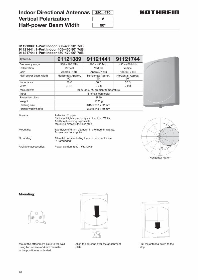
91121389: 1-Port Indoor 380–405 90° 7dBi91121441: 1-Port Indoor 405–430 90° 7dBi91121744: 1-Port Indoor 450–470 90° 7dBi
Type No. 91121389 91121441 91121744Frequency range 380 – 405 MHz 405 – 430 MHz 450 – 470 MHzPolarization Vertical Vertical VerticalGain Approx. 7 dBi Approx. 7 dBi Approx. 7 dBiHalf-power beam width Horizontal: Approx.
90°Horizontal: Approx.
90°Horizontal: Approx.
90°Impedance 50 Ω 50 Ω 50 ΩVSWR < 2.0 < 2.0 < 2.0Max. power 50 W (at 50 °C ambient temperature)Input N female connectorProtection class IP 30Weight 1390 gPacking size 315 x 252 x 62 mmHeight/width/depth 302 x 243 x 50 mm
Material: Reflector: Copper.Radome: High impact polystyrol, colour: White.Additional painting is possible.Mounting plates: Stainless steel.
Mounting: Two holes of 6 mm diameter in the mounting plate. Screws are not supplied.
Grounding: All metal parts including the inner conductor are DC grounded.
Available accessories: Power splitters (380 – 512 MHz)3 dB
10
0
90°
Horizontal Pattern
Pull the antenna down to the stop.
Mount the attachment plate to the wall using two screws of 4 mm diameter in the position as indicated.
Align the antenna over the attachment plate.
Mounting:
27
380
–50
0 M
Hz
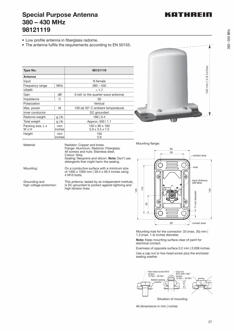
Special Purpose Antenna380 – 430 MHz98121119n Low profile antenna in fiberglass radome.n The antenna fulfils the requirements according to EN 50155.
Type No. 98121119
AntennaInput N femaleFrequency range MHz 380 – 430VSWR < 1.7Gain dB 0 (ref. to the quarter-wave antenna)Impedance Ω 50Polarization VerticalMax. power W 100 (at 50° C ambient temperature)Inner conductor DC groundedRadome weight g | lb 186 | 0.4Total weight g | lb Approx. 500 | 1.1Packing size, L x W x H
mminches
150 x 90 x 1905.9 x 3.5 x 7.5
Height mminches
1505.9
Material: Radiator: Copper and brass.Flange: Aluminum. Radome: Fiberglass.All screws and nuts: Stainless steel.Colour: Grey.Sealing: Neoprene and silicon. Note: Don’t use detergents that might harm the sealing.
Mounting: On a conductive surface with a minimum size of 1000 x 1000 mm | 39.4 x 39.4 inches using 4 M10 bolts.
Grounding andhigh voltage protection:
This antenna, tested by an independent institute, is DC grounded to protect against lightning and high-tension lines.
contact area
contact area
seal
Input Antenna 400 MHz
82
5685
145 11
543
142
11 m
m d
iam
eter
32
Mounting flange:
Situation of mounting
Mounting hole for the connector: 33 (max. 35) mm | 1.3 (max. 1.4) inches diameter.
Note: Keep mounting surface clear of paint for electrical contact.
Evenness of opposite surface 0.2 mm | 0.008 inches.
Use a cap nut or hex-head screw plus the enclosed sealing washer.
Cap nut M10 DIN 1587 torque 15 Nm – 20 Nm Added sealing
washer
5 1
Hex-head screw M10 torque 15 Nm – 20 Nm
15 |
0.6
All dimensions in mm | inches
28
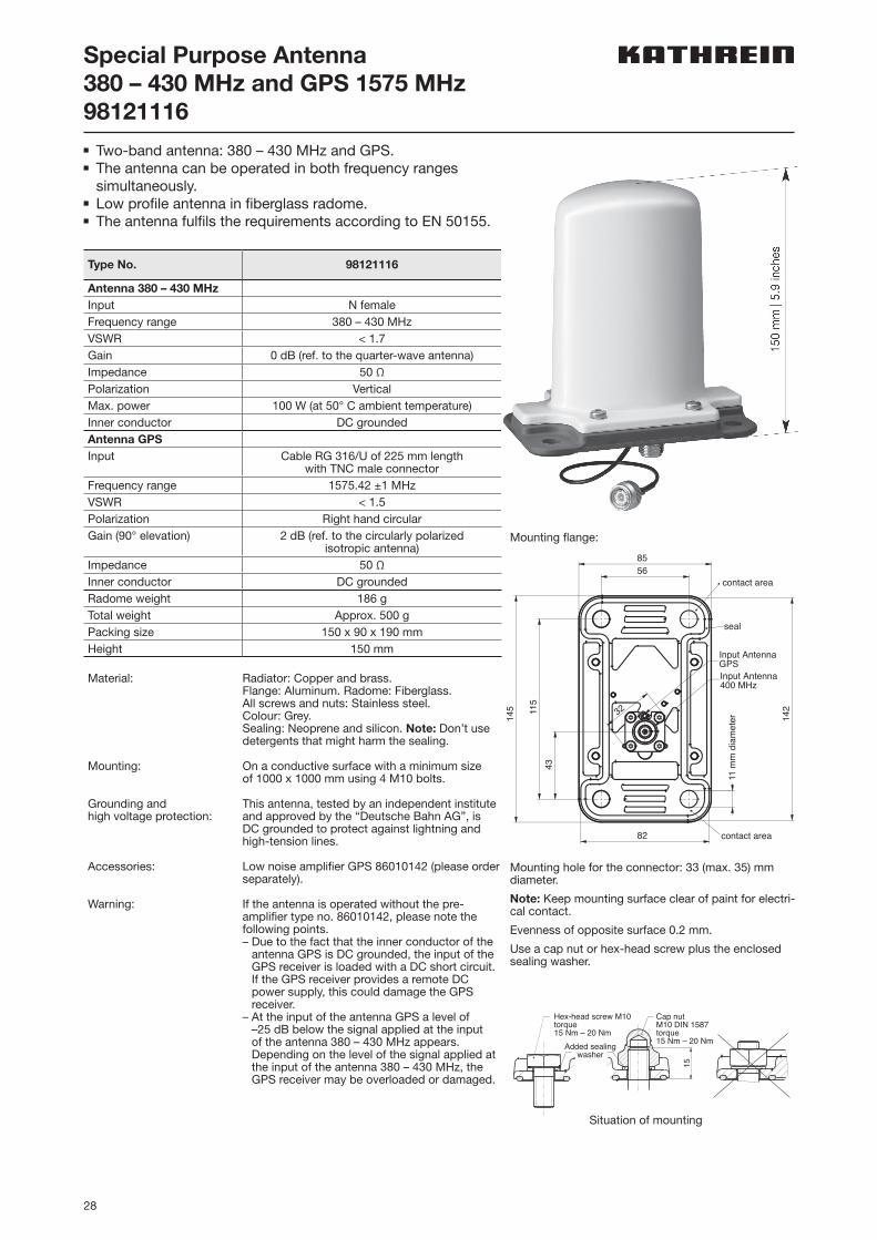
Special Purpose Antenna380 – 430 MHz and GPS 1575 MHz98121116n Two-band antenna: 380 – 430 MHz and GPS.n The antenna can be operated in both frequency ranges
simultaneously.n Low profile antenna in fiberglass radome.n The antenna fulfils the requirements according to EN 50155.
Type No. 98121116
Antenna 380 – 430 MHzInput N femaleFrequency range 380 – 430 MHzVSWR < 1.7Gain 0 dB (ref. to the quarter-wave antenna)Impedance 50 ΩPolarization VerticalMax. power 100 W (at 50° C ambient temperature)Inner conductor DC groundedAntenna GPSInput Cable RG 316/U of 225 mm length
with TNC male connectorFrequency range 1575.42 ±1 MHzVSWR < 1.5Polarization Right hand circularGain (90° elevation) 2 dB (ref. to the circularly polarized
isotropic antenna)Impedance 50 ΩInner conductor DC groundedRadome weight 186 gTotal weight Approx. 500 gPacking size 150 x 90 x 190 mmHeight 150 mm
Material: Radiator: Copper and brass.Flange: Aluminum. Radome: Fiberglass.All screws and nuts: Stainless steel.Colour: Grey.Sealing: Neoprene and silicon. Note: Don’t use detergents that might harm the sealing.
Mounting: On a conductive surface with a minimum size of 1000 x 1000 mm using 4 M10 bolts.
Grounding andhigh voltage protection:
This antenna, tested by an independent institute and approved by the “Deutsche Bahn AG”, is DC grounded to protect against lightning and high-tension lines.
Accessories: Low noise amplifier GPS 86010142 (please order separately).
Warning: If the antenna is operated without the pre- amplifier type no. 86010142, please note the following points.– Due to the fact that the inner conductor of the
antenna GPS is DC grounded, the input of the GPS receiver is loaded with a DC short circuit. If the GPS receiver provides a remote DC power supply, this could damage the GPS receiver.
– At the input of the antenna GPS a level of –25 dB below the signal applied at the input of the antenna 380 – 430 MHz appears. Depending on the level of the signal applied at the input of the antenna 380 – 430 MHz, the GPS receiver may be overloaded or damaged.
contact area
contact area
seal
Input Antenna 400 MHz
82
5685
145 11
543
142
11 m
m d
iam
eter
32
Input AntennaGPS
Mounting hole for the connector: 33 (max. 35) mm diameter.
Note: Keep mounting surface clear of paint for electri-cal contact.
Evenness of opposite surface 0.2 mm.
Use a cap nut or hex-head screw plus the enclosed sealing washer.
Cap nutM10 DIN 1587torque15 Nm – 20 NmAdded sealing
washer
51
Hex-head screw M10torque15 Nm – 20 Nm
Situation of mounting
Mounting flange:
29
380
–50
0 M
Hz
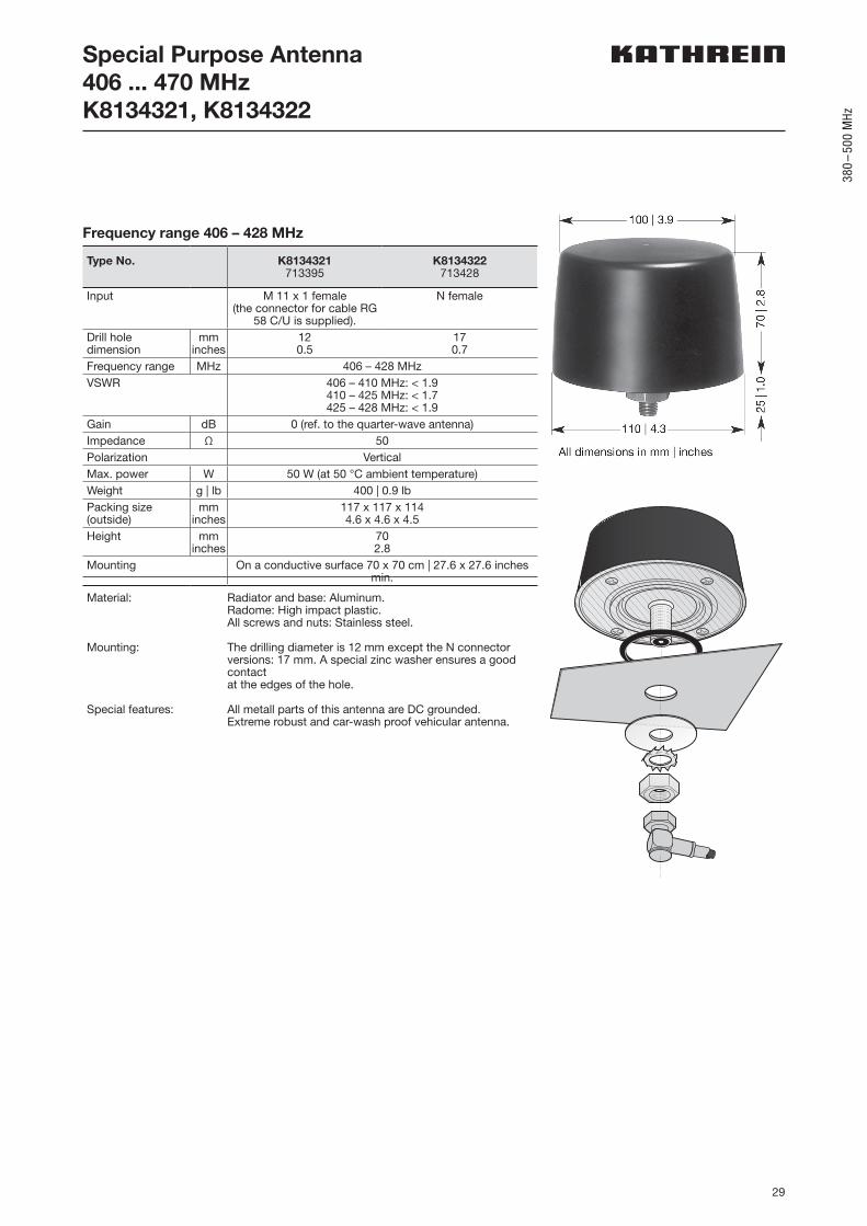
Special Purpose Antenna406 ... 470 MHzK8134321, K8134322
Frequency range 406 – 428 MHz
Type No. K8134321713395
K8134322713428
Input M 11 x 1 female(the connector for cable RG
58 C/U is supplied).
N female
Drill hole dimension
mminches
120.5
170.7
Frequency range MHz 406 – 428 MHzVSWR 406 – 410 MHz: < 1.9
410 – 425 MHz: < 1.7425 – 428 MHz: < 1.9
Gain dB 0 (ref. to the quarter-wave antenna)Impedance Ω 50Polarization VerticalMax. power W 50 W (at 50 °C ambient temperature)Weight g | lb 400 | 0.9 lbPacking size (outside)
mminches
117 x 117 x 1144.6 x 4.6 x 4.5
Height mminches
702.8
Mounting On a conductive surface 70 x 70 cm | 27.6 x 27.6 inches min.
Material: Radiator and base: Aluminum.Radome: High impact plastic.All screws and nuts: Stainless steel.
Mounting: The drilling diameter is 12 mm except the N connector versions: 17 mm. A special zinc washer ensures a good contact at the edges of the hole.
Special features: All metall parts of this antenna are DC grounded.Extreme robust and car-wash proof vehicular antenna.
30
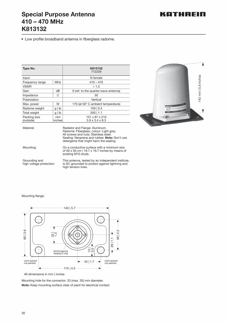
Special Purpose Antenna410 – 470 MHzK813132n Low profile broadband antenna in fiberglass radome.
Mounting hole for the connector: 33 (max. 35) mm diameter.
Note: Keep mounting surface clear of paint for electrical contact.
Mounting flange:
13 |
0.5
115 | 4.5
43 | 1.7
145 | 5.7
80 |
3.6
32 |
1.3
56 |
2.2
28 |
1.1
nicht lackiertnot painted
nicht lackiertnot painted
DichtungsringSealing O-ring
All dimensions in mm | inches
Type No. K813132712229
Input N femaleFrequency range MHz 410 – 470VSWR < 1.5Gain dB 0 (ref. to the quarter-wave antenna)Impedance Ω 50Polarization VerticalMax. power W 170 (at 50° C ambient temperature)Radome weight g | lb 159 | 0.4Total weight g | lb 500 | 1.1Packing size (outside)
mminches
151 x 87 x 2105.9 x 3.4 x 8.3
Material: Radiator and Flange: Aluminum.Radome: Fiberglass, colour: Light grey.All screws and nuts: Stainless steel.Sealing: Neoprene and rubber. Note: Don’t use detergents that might harm the sealing.
Mounting: On a conductive surface with a minimum size of 50 x 50 cm | 19.7 x 19.7 inches by means of existing M10 studs.
Grounding andhigh voltage protection:
This antenna, tested by an independent institute, is DC grounded to protect against lightning and high-tension lines.

31
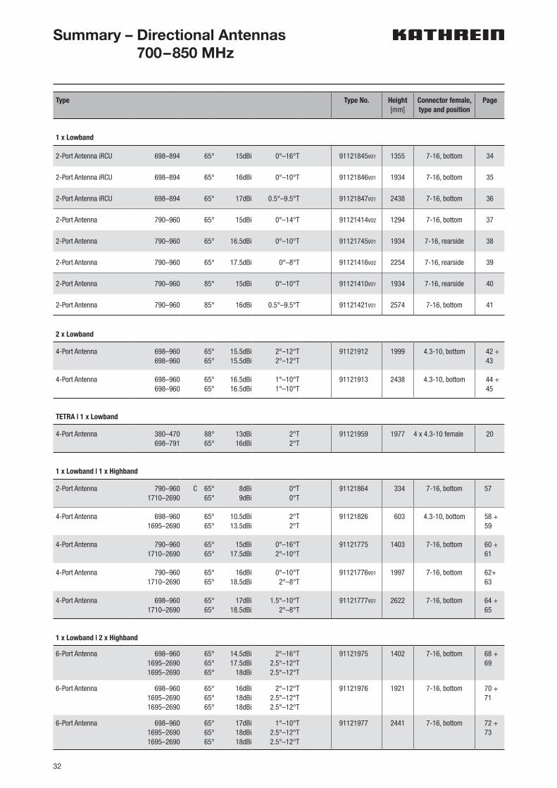
32
Type Type No. Height[mm]
Connector female,type and position
Page
1 x Lowband
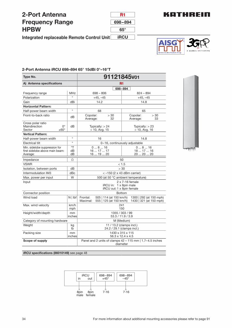
2-Port Antenna iRCU 698–894 65° 15dBi 0°–16°T 91121845V01 1355 7-16, bottom 34
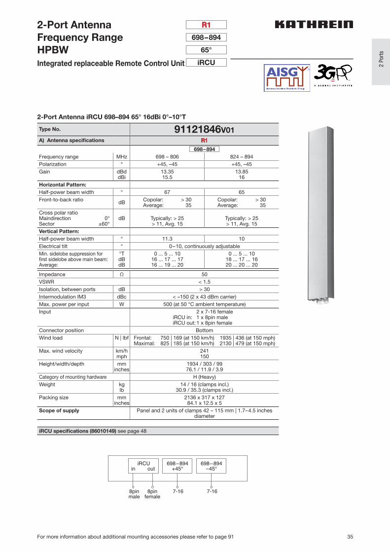
2-Port Antenna iRCU 698–894 65° 16dBi 0°–10°T 91121846V01 1934 7-16, bottom 35
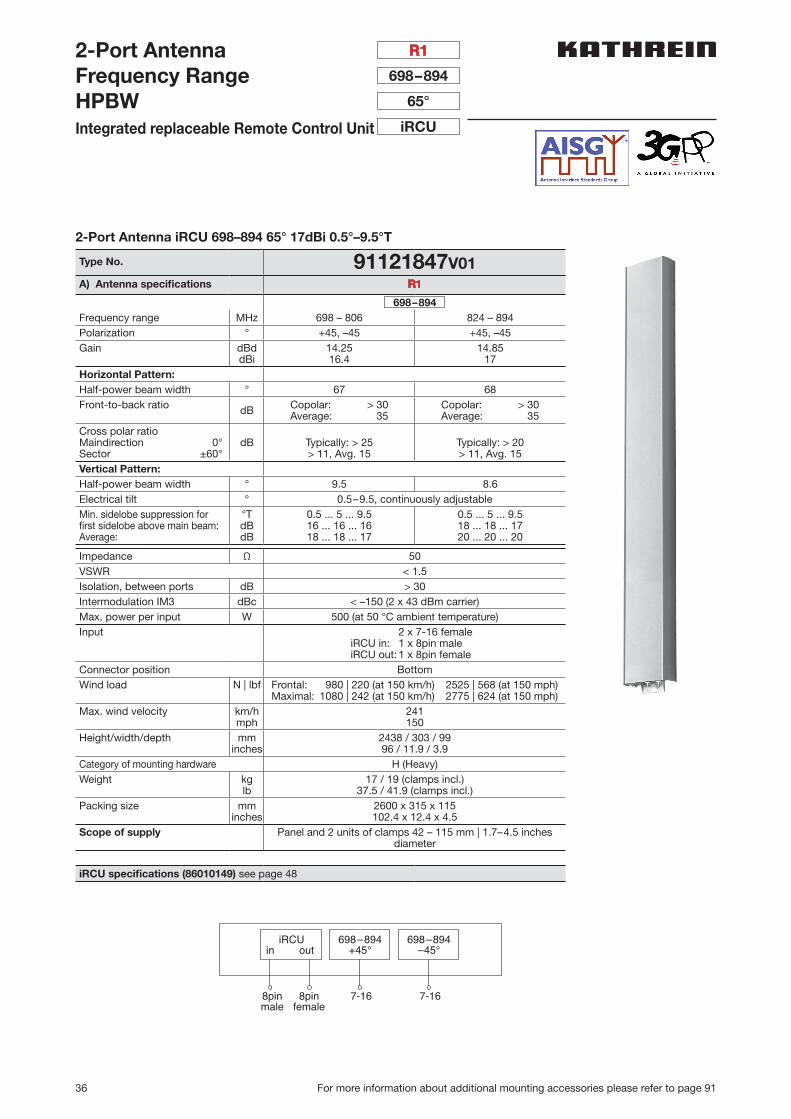
2-Port Antenna iRCU 698–894 65° 17dBi 0.5°–9.5°T 91121847V01 2438 7-16, bottom 36
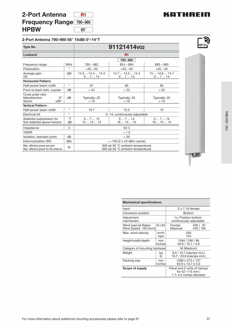
2-Port Antenna 790–960 65° 15dBi 0°–14°T 91121414V02 1294 7-16, bottom 37
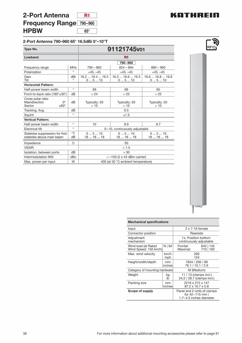
2-Port Antenna 790–960 65° 16.5dBi 0°–10°T 91121745V01 1934 7-16, rearside 38
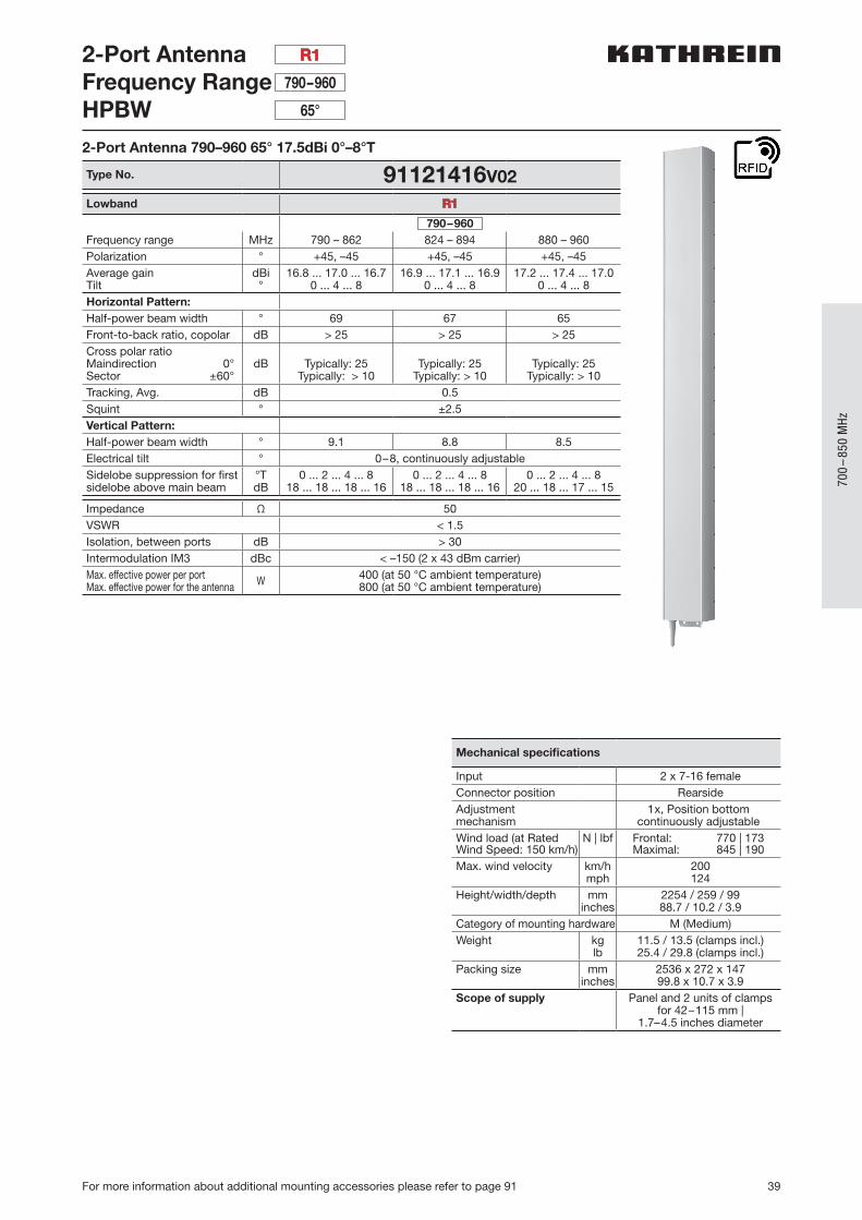
2-Port Antenna 790–960 65° 17.5dBi 0°–8°T 91121416V02 2254 7-16, rearside 39
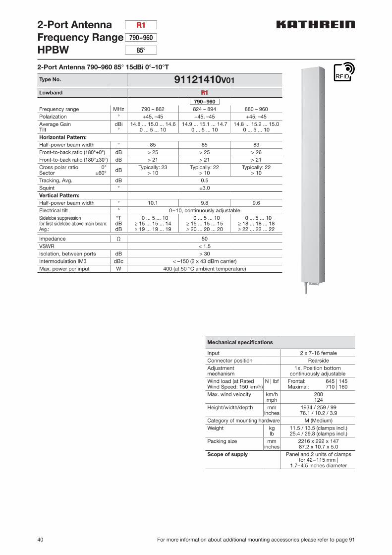
2-Port Antenna 790–960 85° 15dBi 0°–10°T 91121410V01 1934 7-16, rearside 40
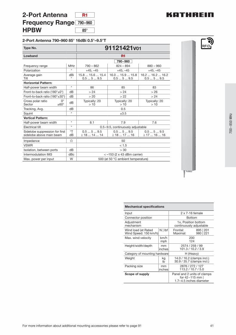
2-Port Antenna 790–960 85° 16dBi 0.5°–9.5°T 91121421V01 2574 7-16, bottom 41
2 x Lowband
4-Port Antenna 698–960698–960
65°65°
15.5dBi15.5dBi
2°–12°T2°–12°T
91121912 1999 4.3-10, bottom 42 +43
4-Port Antenna 698–960698–960
65°65°
16.5dBi16.5dBi
1°–10°T1°–10°T
91121913 2438 4.3-10, bottom 44 +45
TETRA | 1 x Lowband
4-Port Antenna 380–470698–791
88°65°
13dBi16dBi
2°T2°T
91121959 1977 4 x 4.3-10 female 20
1 x Lowband | 1 x Highband
2-Port Antenna 790–9601710–2690
C 65°65°
8dBi9dBi
0°T0°T
91121864 334 7-16, bottom 57
4-Port Antenna 698–9601695–2690
65°65°
10.5dBi13.5dBi
2°T2°T
91121826 603 4.3-10, bottom 58 +59
4-Port Antenna 790–9601710–2690
65°65°
15dBi17.5dBi
0°–16°T2°–10°T
91121775 1403 7-16, bottom 60 +61
4-Port Antenna 790–9601710–2690
65°65°
16dBi18.5dBi
0°–10°T2°–8°T
91121776V01 1997 7-16, bottom 62+63
4-Port Antenna 698–9601710–2690
65°65°
17dBi18.5dBi
1.5°–10°T2°–8°T
91121777V01 2622 7-16, bottom 64 +65
1 x Lowband | 2 x Highband
6-Port Antenna 698–9601695–26901695–2690
65°65°65°
14.5dBi17.5dBi
18dBi
2°–16°T2.5°–12°T2.5°–12°T
91121975 1402 7-16, bottom 68 +69
6-Port Antenna 698–9601695–26901695–2690
65°65°65°
16dBi18dBi18dBi
2°–12°T2.5°–12°T2.5°–12°T
91121976 1921 7-16, bottom 70 +71
6-Port Antenna 698–9601695–26901695–2690
65°65°65°
17dBi18dBi18dBi
1°–10°T2.5°–12°T2.5°–12°T
91121977 2441 7-16, bottom 72 +73
Summary – Directional Antennas 700–850 MHz
33
700
–85
0 M
Hz
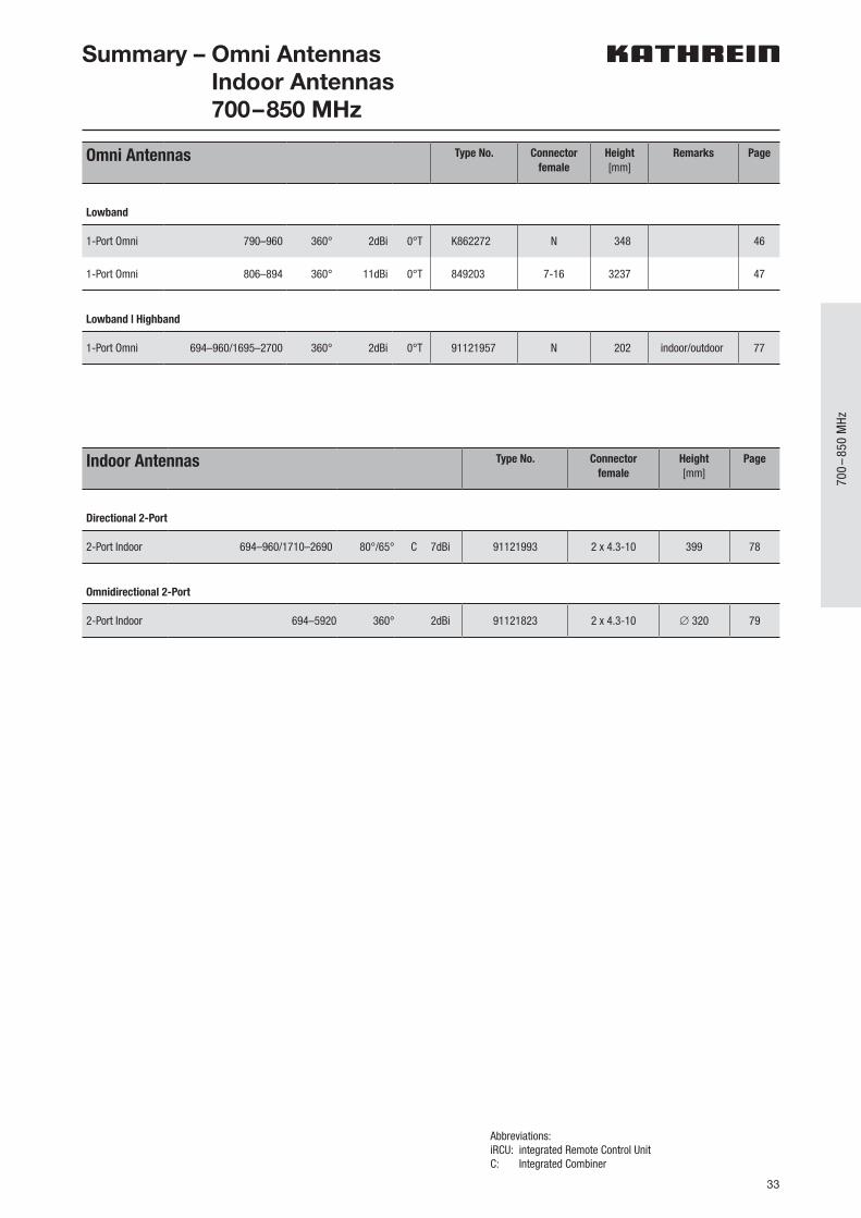
Omni Antennas Type No. Connectorfemale
Height[mm]
Remarks Page
Lowband
1-Port Omni 790–960 360° 2dBi 0°T K862272 N 348 46
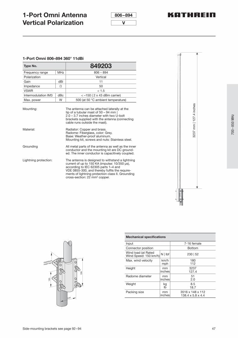
1-Port Omni 806–894 360° 11dBi 0°T 849203 7-16 3237 47
Lowband | Highband
1-Port Omni 694–960/1695–2700 360° 2dBi 0°T 91121957 N 202 indoor/outdoor 77
Abbreviations:iRCU: integrated Remote Control Unit C: Integrated Combiner
Summary – Omni Antennas Indoor Antennas 700–850 MHz
Indoor Antennas Type No. Connectorfemale
Height[mm]
Page
Directional 2-Port
2-Port Indoor 694–960/1710–2690 80°/65° C 7dBi 91121993 2 x 4.3-10 399 78
Omnidirectional 2-Port
2-Port Indoor 694–5920 360° 2dBi 91121823 2 x 4.3-10 ∅ 320 79
34 For more information about additional mounting accessories please refer to page 91
2-Port AntennaFrequency RangeHPBWIntegrated replaceable Remote Control Unit
698–894
65°
iRCU
698–894–45°
7-16
698–894+45°
7-16
iRCUin out
8pinmale
8pinfemale
R1
2-Port Antenna iRCU 698–894 65° 15dBi 0°–16°T
Type No. 91121845V01A) Antenna specifications R1
698–894Frequency range MHz 698 – 806 824 – 894Polarization ° +45, –45 +45, –45Gain dBi 14.2 14.8Horizontal Pattern:Half-power beam width ° 68 65Front-to-back ratio dB Copolar: > 30
Average: 32Copolar: > 30 Average: 33
Cross polar ratioMaindirection 0°Sector ±60°
dB Typically: > 24> 10, Avg. 15
Typically: > 23> 10, Avg. 16
Vertical Pattern:Half-power beam width ° 16 14.8Electrical tilt ° 0–16, continuously adjustableMin. sidelobe suppression for first sidelobe above main beam:Average:
°TdBdB
0 ... 8 ... 1616 ... 17 ... 1716 ... 19 ... 20
0 ... 8 ... 1618 ... 17 ... 1620 ... 20 ... 20
Impedance Ω 50VSWR < 1.5Isolation, between ports dB > 30Intermodulation IM3 dBc < –150 (2 x 43 dBm carrier)Max. power per input W 500 (at 50 °C ambient temperature)Input 2 x 7-16 female
iRCU in: 1 x 8pin maleiRCU out: 1 x 8pin female
Connector position BottomWind load N | lbf Frontal: 505 | 114 (at 150 km/h) 1300 | 292 (at 150 mph)
Maximal: 555 | 125 (at 150 km/h) 1430 | 321 (at 150 mph)Max. wind velocity km/h
mph241150
Height/width/depth mminches
1355 / 303 / 9953.3 / 11.9 / 3.9
Category of mounting hardware M (Medium)Weight kg
lb11 / 13.2 (clamps incl.)
24.2 / 29.1 (clamps incl.)Packing size mm
inches1430 x 315 x 11556.3 x 12.4 x 4.5
Scope of supply Panel and 2 units of clamps 42 – 115 mm | 1.7–4.5 inches diameter
iRCU specifications (86010149) see page 48
35For more information about additional mounting accessories please refer to page 91
2 Po
rts
2-Port AntennaFrequency RangeHPBWIntegrated replaceable Remote Control Unit
698–894
65°
iRCU
698–894–45°
7-16
698–894+45°
7-16
iRCUin out
8pinmale
8pinfemale
R1
2-Port Antenna iRCU 698–894 65° 16dBi 0°–10°T
Type No. 91121846V01A) Antenna specifications R1
698–894Frequency range MHz 698 – 806 824 – 894Polarization ° +45, –45 +45, –45Gain dBd
dBi13.3515.5
13.8516
Horizontal Pattern:Half-power beam width ° 67 65Front-to-back ratio dB Copolar: > 30
Average: 35 Copolar: > 30 Average: 35
Cross polar ratioMaindirection 0°Sector ±60°
dB Typically: > 25> 11, Avg. 15
Typically: > 25> 11, Avg. 15
Vertical Pattern:Half-power beam width ° 11.3 10Electrical tilt ° 0–10, continuously adjustableMin. sidelobe suppression for first sidelobe above main beam:Average:
°TdBdB
0 ... 5 ... 1016 ... 17 ... 1716 ... 19 ... 20
0 ... 5 ... 1018 ... 17 ... 1620 ... 20 ... 20
Impedance Ω 50VSWR < 1.5Isolation, between ports dB > 30Intermodulation IM3 dBc < –150 (2 x 43 dBm carrier)Max. power per input W 500 (at 50 °C ambient temperature)Input 2 x 7-16 female
iRCU in: 1 x 8pin maleiRCU out: 1 x 8pin female
Connector position BottomWind load N | lbf Frontal: 750 | 169 (at 150 km/h) 1935 | 436 (at 150 mph)
Maximal: 825 | 185 (at 150 km/h) 2130 | 479 (at 150 mph)Max. wind velocity km/h
mph241150
Height/width/depth mminches
1934 / 303 / 9976.1 / 11.9 / 3.9
Category of mounting hardware H (Heavy)Weight kg
lb14 / 16 (clamps incl.)
30.9 / 35.3 (clamps incl.)Packing size mm
inches2136 x 317 x 12784.1 x 12.5 x 5
Scope of supply Panel and 2 units of clamps 42 – 115 mm | 1.7–4.5 inches diameter
iRCU specifications (86010149) see page 48
36 For more information about additional mounting accessories please refer to page 91
698–894–45°
7-16
698–894+45°
7-16
iRCUin out
8pinmale
8pinfemale
2-Port AntennaFrequency RangeHPBWIntegrated replaceable Remote Control Unit
698–894
65°
iRCU
R1
2-Port Antenna iRCU 698–894 65° 17dBi 0.5°–9.5°T
Type No. 91121847V01A) Antenna specifications R1
698–894Frequency range MHz 698 – 806 824 – 894Polarization ° +45, –45 +45, –45Gain dBd
dBi14.2516.4
14.8517
Horizontal Pattern:Half-power beam width ° 67 68Front-to-back ratio dB Copolar: > 30
Average: 35Copolar: > 30Average: 35
Cross polar ratioMaindirection 0°Sector ±60°
dB Typically: > 25> 11, Avg. 15
Typically: > 20> 11, Avg. 15
Vertical Pattern:Half-power beam width ° 9.5 8.6Electrical tilt ° 0.5–9.5, continuously adjustableMin. sidelobe suppression for first sidelobe above main beam:Average:
°TdBdB
0.5 ... 5 ... 9.516 ... 16 ... 1618 ... 18 ... 17
0.5 ... 5 ... 9.518 ... 18 ... 1720 ... 20 ... 20
Impedance Ω 50VSWR < 1.5Isolation, between ports dB > 30Intermodulation IM3 dBc < –150 (2 x 43 dBm carrier)Max. power per input W 500 (at 50 °C ambient temperature)Input 2 x 7-16 female
iRCU in: 1 x 8pin maleiRCU out: 1 x 8pin female
Connector position BottomWind load N | lbf Frontal: 980 | 220 (at 150 km/h) 2525 | 568 (at 150 mph)
Maximal: 1080 | 242 (at 150 km/h) 2775 | 624 (at 150 mph)Max. wind velocity km/h
mph241150
Height/width/depth mminches
2438 / 303 / 9996 / 11.9 / 3.9
Category of mounting hardware H (Heavy)Weight kg
lb17 / 19 (clamps incl.)
37.5 / 41.9 (clamps incl.)Packing size mm
inches2600 x 315 x 115102.4 x 12.4 x 4.5
Scope of supply Panel and 2 units of clamps 42 – 115 mm | 1.7–4.5 inches diameter
iRCU specifications (86010149) see page 48
37
700
–85
0 M
Hz
For more information about additional mounting accessories please refer to page 91
2-Port AntennaFrequency RangeHPBW
790–960
65°
R1
2-Port Antenna 790–960 65° 15dBi 0°–14°T
Type No. 91121414V02Lowband R1
790–960Frequency range MHz 790 – 862 824 – 894 880 – 960Polarization ° +45, –45 +45, –45 +45, –45Average gainTilt
dBi°
14.5 ... 14.4 ... 14.30 ... 7 ... 14
14.7 ... 14.5 ... 14.40 ... 7 ... 14
15 ... 14.8 ... 14.70 ... 7 ... 14
Horizontal Pattern:Half-power beam width ° 67 66 65Front-to-back ratio, copolar dB > 24 > 25 > 25Cross polar ratioMaindirection 0°Sector ±60°
dB Typically: 25> 10
Typically: 25> 10
Typically: 25> 10
Vertical Pattern:Half-power beam width ° 15.7 15.5 15Electrical tilt ° 0–14, continuously adjustableSidelobe suppression for first sidelobe above horizon
°TdB
0 ... 7 ... 1415 ... 14 ... 15
0 ... 7 ... 1418 ... 15 ... 15
0 ... 7 ... 1418 ... 15 ... 15
Impedance Ω 50 ΩVSWR < 1.5Isolation, between ports dB > 30Intermodulation IM3 dBc < –150 (2 x 43 dBm carrier)Max. effective power per portMax. effective power for the antenna W 300 (at 50 °C ambient temperature)
600 (at 50 °C ambient temperature)
Mechanical specifications
Input 2 x 7-16 femaleConnector position BottomAdjustmentmechanism
1x, Position bottomcontinuously adjustable
Wind load (at Rated Wind Speed: 150 km/h)
N | lbf Frontal: 405 | 91Maximal: 445 | 100
Max. wind velocity km/hmph
200124
Height/width/depth mminches
1294 / 256 / 9950.9 / 10.1 / 3.9
Category of mounting hardware M (Medium)Weight kg
lb8.5 / 10.7 (clamps incl.)18.7 / 23.6 (clamps incl.)
Packing size mminches
1596 x 272 x 12762.8 x 10.7 x 5.0
Scope of supply Panel and 2 units of clamps for 42–115 mm |
1.7–4.5 inches diameter
38 For more information about additional mounting accessories please refer to page 91
2-Port AntennaFrequency RangeHPBW
790–960
65°
R1
2-Port Antenna 790–960 65° 16.5dBi 0°–10°T
Type No. 91121745V01Lowband R1
790–960Frequency range MHz 790 – 862 824 – 894 880 – 960Polarization ° +45, –45 +45, –45 +45, –45GainTilt
dBi°
16.2 ... 16.4 ... 16.20 ... 5 ... 10
16.3 ... 16.6 ... 16.30 ... 5 ... 10
16.6 ... 16.8 ... 16.60 ... 5 ... 10
Horizontal Pattern:Half-power beam width ° 69 68 65Front-to-back ratio (180°±30°) dB > 24 > 25 > 25Cross polar ratioMaindirection 0°Sector ±60°
dB Typically: 20> 10
Typically: 20> 10
Typically: 20> 10
Tracking, Avg. dB 0.5Squint ° ±1.5Vertical Pattern:Half-power beam width ° 10 9.9 9.7Electrical tilt ° 0–10, continuously adjustableSidelobe suppression for first sidelobe above main beam
°TdB
0 ... 5 ... 1018 ... 18 ... 18
0 ... 5 ... 1018 ... 18 ... 18
0 ... 5 ... 1018 ... 18 ... 18
Impedance Ω 50VSWR < 1.5Isolation, between ports dB > 30Intermodulation IM3 dBc < –150 (2 x 43 dBm carrier)Max. power per input W 400 (at 50 °C ambient temperature)
Mechanical specifications
Input 2 x 7-16 femaleConnector position RearsideAdjustmentmechanism
1x, Position bottomcontinuously adjustable
Wind load (at Rated Wind Speed: 150 km/h)
N | lbf Frontal: 645 | 145Maximal: 710 | 160
Max. wind velocity km/hmph
200124
Height/width/depth mminches
1934 / 256 / 9976.1 / 10.1 / 3.9
Category of mounting hardware M (Medium)Weight kg
lb11 / 13 (clamps incl.)
24.2 / 28.7 (clamps incl.)Packing size mm
inches2216 x 272 x 14787.2 x 10.7 x 5.8
Scope of supply Panel and 2 units of clamps for 42–115 mm |
1.7–4.5 inches diameter
39
700
–85
0 M
Hz
For more information about additional mounting accessories please refer to page 91
2-Port AntennaFrequency RangeHPBW
790–960
65°
R1
2-Port Antenna 790–960 65° 17.5dBi 0°–8°T
Type No. 91121416V02Lowband R1
790–960Frequency range MHz 790 – 862 824 – 894 880 – 960Polarization ° +45, –45 +45, –45 +45, –45Average gainTilt
dBi°
16.8 ... 17.0 ... 16.70 ... 4 ... 8
16.9 ... 17.1 ... 16.90 ... 4 ... 8
17.2 ... 17.4 ... 17.00 ... 4 ... 8
Horizontal Pattern:Half-power beam width ° 69 67 65Front-to-back ratio, copolar dB > 25 > 25 > 25Cross polar ratioMaindirection 0°Sector ±60°
dB Typically: 25Typically: > 10
Typically: 25Typically: > 10
Typically: 25Typically: > 10
Tracking, Avg. dB 0.5Squint ° ±2.5Vertical Pattern:Half-power beam width ° 9.1 8.8 8.5Electrical tilt ° 0–8, continuously adjustableSidelobe suppression for first sidelobe above main beam
°TdB
0 ... 2 ... 4 ... 818 ... 18 ... 18 ... 16
0 ... 2 ... 4 ... 818 ... 18 ... 18 ... 16
0 ... 2 ... 4 ... 820 ... 18 ... 17 ... 15
Impedance Ω 50VSWR < 1.5Isolation, between ports dB > 30Intermodulation IM3 dBc < –150 (2 x 43 dBm carrier)Max. effective power per portMax. effective power for the antenna W 400 (at 50 °C ambient temperature)
800 (at 50 °C ambient temperature)
Mechanical specifications
Input 2 x 7-16 femaleConnector position RearsideAdjustmentmechanism
1x, Position bottomcontinuously adjustable
Wind load (at Rated Wind Speed: 150 km/h)
N | lbf Frontal: 770 | 173Maximal: 845 | 190
Max. wind velocity km/hmph
200124
Height/width/depth mminches
2254 / 259 / 9988.7 / 10.2 / 3.9
Category of mounting hardware M (Medium)Weight kg
lb11.5 / 13.5 (clamps incl.)25.4 / 29.8 (clamps incl.)
Packing size mminches
2536 x 272 x 14799.8 x 10.7 x 3.9
Scope of supply Panel and 2 units of clamps for 42–115 mm |
1.7–4.5 inches diameter
40 For more information about additional mounting accessories please refer to page 91
2-Port AntennaFrequency RangeHPBW
790–960
85°
R1
2-Port Antenna 790–960 85° 15dBi 0°–10°T
Type No. 91121410V01Lowband R1
790–960Frequency range MHz 790 – 862 824 – 894 880 – 960Polarization ° +45, –45 +45, –45 +45, –45Average GainTilt
dBi°
14.8 ... 15.0 ... 14.60 ... 5 ... 10
14.9 ... 15.1 ... 14.70 ... 5 ... 10
14.8 ... 15.2 ... 15.00 ... 5 ... 10
Horizontal Pattern:Half-power beam width ° 85 85 83Front-to-back ratio (180°±0°) dB > 25 > 25 > 26Front-to-back ratio (180°±30°) dB > 21 > 21 > 21Cross polar ratio 0°Sector ±60° dB Typically: 23
> 10Typically: 22
> 10Typically: 22
> 10Tracking, Avg. dB 0.5Squint ° ±3.0Vertical Pattern:Half-power beam width ° 10.1 9.8 9.6Electrical tilt ° 0–10, continuously adjustableSidelobe suppressionfor first sidelobe above main beam:Avg.:
°TdBdB
0 ... 5 ... 10≥ 15 ... 15 ... 14≥ 19 ... 19 ... 19
0 ... 5 ... 10≥ 15 ... 15 ... 15≥ 20 ... 20 ... 20
0 ... 5 ... 10≥ 18 ... 18 ... 18≥ 22 ... 22 ... 22
Impedance Ω 50 VSWR < 1.5Isolation, between ports dB > 30Intermodulation IM3 dBc < –150 (2 x 43 dBm carrier)Max. power per input W 400 (at 50 °C ambient temperature)
Mechanical specifications
Input 2 x 7-16 femaleConnector position RearsideAdjustmentmechanism
1x, Position bottomcontinuously adjustable
Wind load (at Rated Wind Speed: 150 km/h)
N | lbf Frontal: 645 | 145Maximal: 710 | 160
Max. wind velocity km/hmph
200124
Height/width/depth mminches
1934 / 259 / 9976.1 / 10.2 / 3.9
Category of mounting hardware M (Medium)Weight kg
lb11.5 / 13.5 (clamps incl.)25.4 / 29.8 (clamps incl.)
Packing size mminches
2216 x 292 x 14787.2 x 10.7 x 5.0
Scope of supply Panel and 2 units of clamps for 42–115 mm |
1.7–4.5 inches diameter
41
700
–85
0 M
Hz
For more information about additional mounting accessories please refer to page 91
2-Port AntennaFrequency RangeHPBW
790–960
85°
R1
2-Port Antenna 790–960 85° 16dBi 0.5°–9.5°T
Type No. 91121421V01Lowband R1
790–960Frequency range MHz 790 – 862 824 – 894 880 – 960Polarization ° +45, –45 +45, –45 +45, –45Average gainTilt
dBi°
15.8 ... 15.6 ... 15.40.5 ... 5 ... 9.5
16.0 ... 15.9 ... 15.80.5 ... 5 ... 9.5
16.2 ... 16.2 ... 16.20.5 ... 5 ... 9.5
Horizontal Pattern:Half-power beam width ° 86 85 83Front-to-back ratio (180°±0°) dB > 24 > 24 > 26Front-to-back ratio (180°±30°) dB > 20 > 22 > 24Cross polar ratio 0°Sector ±60° dB Typically: 20
> 10Typically: 20
> 10Typically: 20
> 10Tracking, Avg. dB 0.5Squint ° ±3.5Vertical Pattern:Half-power beam width ° 8.1 7.9 7.6Electrical tilt ° 0.5–9.5, continuously adjustableSidelobe suppression for first sidelobe above main beam
°TdB
0.5 ... 5 ... 9.5≥ 18 ... 14 ... 14
0.5 ... 5 ... 9.5≥ 18 ... 17 ... 16
0.5 ... 5 ... 9.5≥ 17 ... 16 ... 16
Impedance Ω 50VSWR < 1.5Isolation, between ports dB > 30Intermodulation IM3 dBc < –153 (2 x 43 dBm carrier)Max. power per input W 500 (at 50 °C ambient temperature)
Mechanical specifications
Input 2 x 7-16 femaleConnector position BottomAdjustmentmechanism
1x, Position bottomcontinuously adjustable
Wind load (at Rated Wind Speed: 150 km/h)
N | lbf Frontal: 895 | 201Maximal: 980 | 221
Max. wind velocity km/hmph
200124
Height/width/depth mminches
2574 / 259 / 99 101.3 / 10.2 / 3.9
Category of mounting hardware H (Heavy)Weight kg
lb14.0 / 16.2 (clamps incl.)30.9 / 35.7 (clamps incl.)
Packing size mminches
2876 / 272 / 127113.2 / 10.7 / 5.0
Scope of supply Panel and 2 units of clamps for 42–115 mm |
1.7–4.5 inches diameter
42 For more information about additional mounting accessories please refer to page 91
4-Port AntennaFrequency RangeHPBW
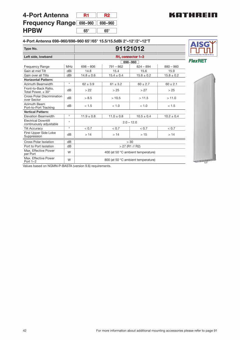
4-Port Antenna 698–960/698–960 65°/65° 15.5/15.5dBi 2°–12°/2°–12°T
Type No. 91121012Left side, lowband R1, connector 1–2
698–960Frequency Range MHz 698 – 806 791 – 862 824 – 894 880 – 960Gain at mid Tilt dBi 14.8 15.4 15.6 15.9Gain over all Tilts dBi 14.8 ± 0.6 15.4 ± 0.4 15.6 ± 0.2 15.8 ± 0.2Horizontal Pattern:Azimuth Beamwidth ° 62 ± 3.9 61 ± 3.2 60 ± 2.7 60 ± 2.1Front-to-Back Ratio,Total Power, ± 30° dB > 22 > 25 > 27 > 25
Cross Polar Discriminationover Sector dB > 8.5 > 10.5 > 11.5 > 11.0
Azimuth Beam Port-to-Port Tracking dB < 1.5 < 1.0 < 1.0 < 1.5
Vertical Pattern:Elevation Beamwidth ° 11.9 ± 0.8 11.0 ± 0.8 10.5 ± 0.4 10.2 ± 0.4Electrical Downtiltcontinuously adjustable ° 2.0 – 12.0
Tilt Accuracy ° < 0.7 < 0.7 < 0.7 < 0.7First Upper Side Lobe Suppression dB > 14 > 14 > 15 > 14
Cross Polar Isolation dB > 30Port to Port Isolation dB > 27 (R1 // R2)Max. Effective Powerper Port W 400 (at 50 °C ambient temperature)
Max. Effective PowerPort 1–2 W 800 (at 50 °C ambient temperature)
Values based on NGMN-P-BASTA (version 9.6) requirements.
698–960698–960
65°65°
R2R1
43
700
–85
0 M
Hz
For more information about additional mounting accessories please refer to page 91
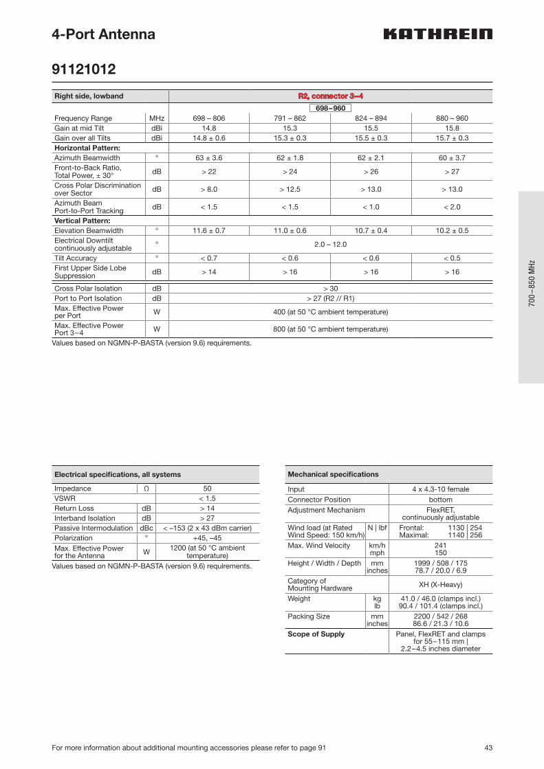
4-Port Antenna
91121012
Right side, lowband R2, connector 3–4
698–960Frequency Range MHz 698 – 806 791 – 862 824 – 894 880 – 960Gain at mid Tilt dBi 14.8 15.3 15.5 15.8Gain over all Tilts dBi 14.8 ± 0.6 15.3 ± 0.3 15.5 ± 0.3 15.7 ± 0.3Horizontal Pattern:Azimuth Beamwidth ° 63 ± 3.6 62 ± 1.8 62 ± 2.1 60 ± 3.7Front-to-Back Ratio,Total Power, ± 30° dB > 22 > 24 > 26 > 27
Cross Polar Discriminationover Sector dB > 8.0 > 12.5 > 13.0 > 13.0
Azimuth Beam Port-to-Port Tracking dB < 1.5 < 1.5 < 1.0 < 2.0
Vertical Pattern:Elevation Beamwidth ° 11.6 ± 0.7 11.0 ± 0.6 10.7 ± 0.4 10.2 ± 0.5Electrical Downtiltcontinuously adjustable ° 2.0 – 12.0
Tilt Accuracy ° < 0.7 < 0.6 < 0.6 < 0.5First Upper Side Lobe Suppression dB > 14 > 16 > 16 > 16
Cross Polar Isolation dB > 30Port to Port Isolation dB > 27 (R2 // R1)Max. Effective Powerper Port W 400 (at 50 °C ambient temperature)
Max. Effective PowerPort 3–4 W 800 (at 50 °C ambient temperature)
Values based on NGMN-P-BASTA (version 9.6) requirements.
Electrical specifications, all systems
Impedance Ω 50VSWR < 1.5Return Loss dB > 14Interband Isolation dB > 27Passive Intermodulation dBc < –153 (2 x 43 dBm carrier)Polarization ° +45, –45Max. Effective Powerfor the Antenna W 1200 (at 50 °C ambient
temperature)Values based on NGMN-P-BASTA (version 9.6) requirements.
Mechanical specifications
Input 4 x 4.3-10 femaleConnector Position bottomAdjustment Mechanism FlexRET,
continuously adjustableWind load (at Rated Wind Speed: 150 km/h)
N | lbf Frontal: 1130 | 254Maximal: 1140 | 256
Max. Wind Velocity km/hmph
241150
Height / Width / Depth mminches
1999 / 508 / 17578.7 / 20.0 / 6.9
Category of Mounting Hardware XH (X-Heavy)
Weight kglb
41.0 / 46.0 (clamps incl.)90.4 / 101.4 (clamps incl.)
Packing Size mminches
2200 / 542 / 26886.6 / 21.3 / 10.6
Scope of Supply Panel, FlexRET and clampsfor 55–115 mm |
2.2–4.5 inches diameter
44 For more information about additional mounting accessories please refer to page 91
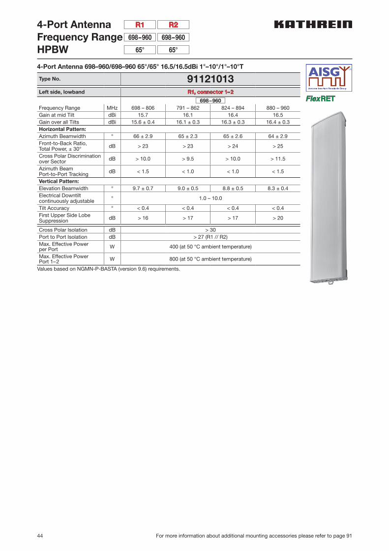
4-Port AntennaFrequency RangeHPBW
698–960698–960
65°65°
R2R1
4-Port Antenna 698–960/698–960 65°/65° 16.5/16.5dBi 1°–10°/1°–10°T
Type No. 91121013Left side, lowband R1, connector 1–2
698–960Frequency Range MHz 698 – 806 791 – 862 824 – 894 880 – 960Gain at mid Tilt dBi 15.7 16.1 16.4 16.5Gain over all Tilts dBi 15.6 ± 0.4 16.1 ± 0.3 16.3 ± 0.3 16.4 ± 0.3Horizontal Pattern:Azimuth Beamwidth ° 66 ± 2.9 65 ± 2.3 65 ± 2.6 64 ± 2.9Front-to-Back Ratio,Total Power, ± 30° dB > 23 > 23 > 24 > 25
Cross Polar Discriminationover Sector dB > 10.0 > 9.5 > 10.0 > 11.5
Azimuth Beam Port-to-Port Tracking dB < 1.5 < 1.0 < 1.0 < 1.5
Vertical Pattern:Elevation Beamwidth ° 9.7 ± 0.7 9.0 ± 0.5 8.8 ± 0.5 8.3 ± 0.4Electrical Downtiltcontinuously adjustable ° 1.0 – 10.0
Tilt Accuracy ° < 0.4 < 0.4 < 0.4 < 0.4First Upper Side Lobe Suppression dB > 16 > 17 > 17 > 20
Cross Polar Isolation dB > 30Port to Port Isolation dB > 27 (R1 // R2)Max. Effective Powerper Port W 400 (at 50 °C ambient temperature)
Max. Effective PowerPort 1–2 W 800 (at 50 °C ambient temperature)
Values based on NGMN-P-BASTA (version 9.6) requirements.

45
700
–85
0 M
Hz
For more information about additional mounting accessories please refer to page 91
4-Port Antenna
91121013
Right side, lowband R2, connector 3–4
698–960Frequency Range MHz 698 – 806 791 – 862 824 – 894 880 – 960Gain at mid Tilt dBi 15.5 16.0 16.3 16.6Gain over all Tilts dBi 15.5 ± 0.5 16.0 ± 0.5 16.3 ± 0.4 16.5 ± 0.3Horizontal Pattern:Azimuth Beamwidth ° 67 ± 3.5 65 ± 2.6 64 ± 3.0 63 ± 4.3Front-to-Back Ratio,Total Power, ± 30° dB > 22 > 23 > 24 > 26
Cross Polar Discriminationover Sector dB > 9.5 > 10.5 > 10.0 > 11.5
Azimuth Beam Port-to-Port Tracking dB < 0.5 < 1.0 < 0.5 < 1.5
Vertical Pattern:Elevation Beamwidth ° 9.9 ± 0.7 9.0 ± 0.7 8.6 ± 0.4 8.1 ± 0.5Electrical Downtiltcontinuously adjustable ° 1.0 – 10.0
Tilt Accuracy ° < 0.4 < 0.4 < 0.4 < 0.3First Upper Side Lobe Suppression dB > 18 > 21 > 20 > 20
Cross Polar Isolation dB > 30Port to Port Isolation dB > 27 (R2 // R1)Max. Effective Powerper Port W 400 (at 50 °C ambient temperature)
Max. Effective PowerPort 3–4 W 800 (at 50 °C ambient temperature)
Values based on NGMN-P-BASTA (version 9.6) requirements.
Electrical specifications, all systems
Impedance Ω 50VSWR < 1.5Return Loss dB > 14Interband Isolation dB > 27Passive Intermodulation dBc < –153 (2 x 43 dBm carrier)Polarization ° +45, –45Max. Effective Powerfor the Antenna W 1200 (at 50 °C ambient
temperature)Values based on NGMN-P-BASTA (version 9.6) requirements.
Mechanical specifications
Input 4 x 4.3-10 femaleConnector Position bottomAdjustment Mechanism FlexRET,
continuously adjustableWind load (at Rated Wind Speed: 150 km/h)
N | lbf Frontal: 1400 | 315Maximal: 1405 | 316
Max. Wind Velocity km/hmph
241150
Height / Width / Depth mminches
2438 / 508 / 17596.0 / 20.0 / 6.9
Category of Mounting Hardware XH (X-Heavy)
Weight kglb
47.0 / 52.0 (clamps incl.)103.6 / 114.6 (clamps incl.)
Packing Size mminches
2635 / 542 / 268103.7 / 21.3 / 10.6
Scope of Supply Panel, FlexRET and 1 unit of clamps for 55–115 mm |
2.2–4.5 inches diameter
46 Side-mounting brackets see page 92–94
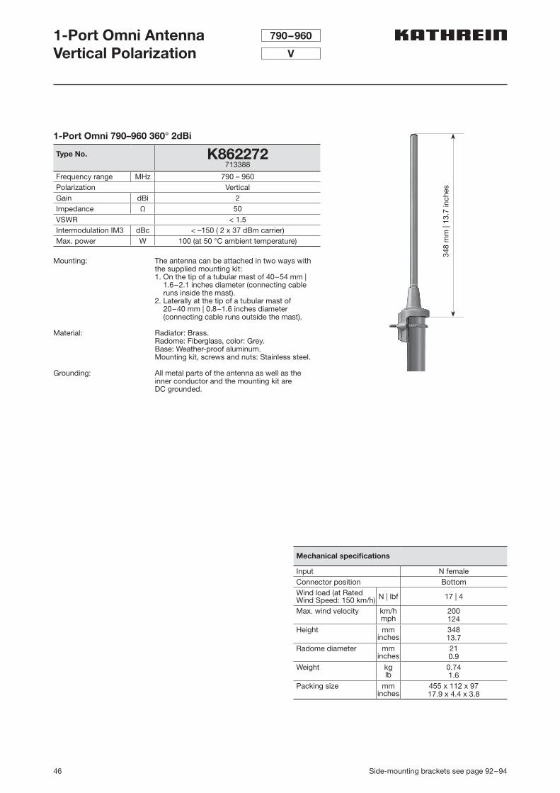
1-Port Omni AntennaVertical Polarization
790–960
V
Mounting: The antenna can be attached in two ways with the supplied mounting kit:1. On the tip of a tubular mast of 40–54 mm |
1.6–2.1 inches diameter (connecting cable runs inside the mast).
2. Laterally at the tip of a tubular mast of 20–40 mm | 0.8–1.6 inches diameter (connecting cable runs outside the mast).
Material: Radiator: Brass. Radome: Fiberglass, color: Grey.Base: Weather-proof aluminum. Mounting kit, screws and nuts: Stainless steel.
Grounding: All metal parts of the antenna as well as the inner conductor and the mounting kit are DC grounded.
1-Port Omni 790–960 360° 2dBi
Type No. K862272713388
Frequency range MHz 790 – 960Polarization VerticalGain dBi 2Impedance Ω 50VSWR < 1.5Intermodulation IM3 dBc < –150 ( 2 x 37 dBm carrier)Max. power W 100 (at 50 °C ambient temperature)
348
mm
| 13
.7 in
ches
Mechanical specifications
Input N femaleConnector position BottomWind load (at Rated Wind Speed: 150 km/h) N | lbf 17 | 4
Max. wind velocity km/hmph
200124
Height mminches
34813.7
Radome diameter mminches
210.9
Weight kglb
0.741.6
Packing size mminches
455 x 112 x 9717.9 x 4.4 x 3.8
47
700
–85
0 M
Hz
Side-mounting brackets see page 92–94
1-Port Omni AntennaVertical Polarization
806–894
V
Mounting: The antenna can be attached laterally at the tip of a tubular mast of 50 – 94 mm | 2.0 – 3.7 inches diameter with two U-bolt brackets supplied with the antenna (connecting cable runs outside the mast).
Material: Radiator: Copper and brass. Radome: Fiberglass, color: Grey.Base: Weather-proof aluminum. Mounting kit, screws and nuts: Stainless steel.
Grounding All metal parts of the antenna as well as the inner conductor and the mounting kit are DC ground-ed. The inner conductor is capacitively coupled.
Lightning protection: The antenna is designed to withstand a lightning current of up to 150 KA (impulse: 10/350 µs), according to IEC 62305 parts 1–4 and VDE 0855-300, and thereby fulfils the require-ments of lightning protection class II. Grounding cross-section: 22 mm2 copper.
1 50
230
104
maximum
mast top
1-Port Omni 806–894 360° 11dBi
Type No. 849203Frequency range MHz 806 – 894Polarization VerticalGain dBi 11Impedance Ω 50VSWR < 1.5Intermodulation IM3 dBc < –150 ( 2 x 43 dBm carrier)Max. power W 500 (at 50 °C ambient temperature)
Mechanical specifications
Input 7-16 femaleConnector position BottomWind load (at Rated Wind Speed: 150 km/h) N | lbf 230 | 52
Max. wind velocity km/hmph
180112
Height mminches
3237127.4
Radome diameter mminches
512.0
Weight kglb
8.518.7
Packing size mminches
3516 x 148 x 112138.4 x 5.8 x 4.4
3237
mm
| 12
7.4
inch
es
48
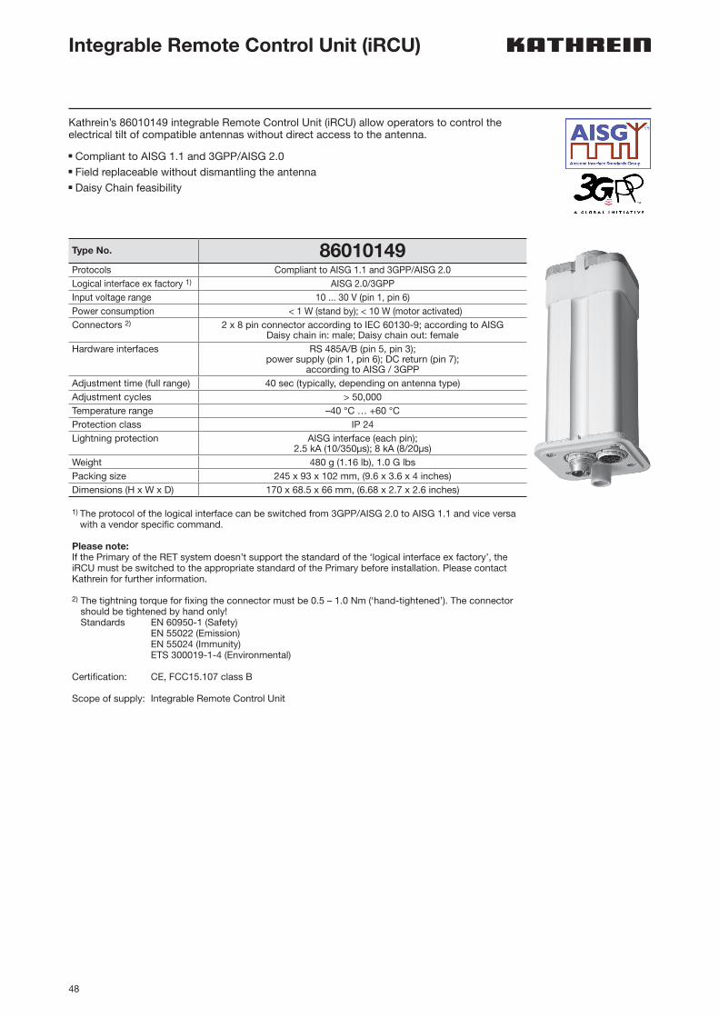
Integrable Remote Control Unit (iRCU)
Type No. 86010149Protocols Compliant to AISG 1.1 and 3GPP/AISG 2.0Logical interface ex factory 1) AISG 2.0/3GPPInput voltage range 10 ... 30 V (pin 1, pin 6)Power consumption < 1 W (stand by); < 10 W (motor activated)Connectors 2) 2 x 8 pin connector according to IEC 60130-9; according to AISG
Daisy chain in: male; Daisy chain out: femaleHardware interfaces RS 485A/B (pin 5, pin 3);
power supply (pin 1, pin 6); DC return (pin 7);according to AISG / 3GPP
Adjustment time (full range) 40 sec (typically, depending on antenna type)Adjustment cycles > 50,000Temperature range –40 °C … +60 °CProtection class IP 24Lightning protection AISG interface (each pin);
2.5 kA (10/350µs); 8 kA (8/20µs)Weight 480 g (1.16 lb), 1.0 G lbsPacking size 245 x 93 x 102 mm, (9.6 x 3.6 x 4 inches)Dimensions (H x W x D) 170 x 68.5 x 66 mm, (6.68 x 2.7 x 2.6 inches)
1) The protocol of the logical interface can be switched from 3GPP/AISG 2.0 to AISG 1.1 and vice versa with a vendor specific command.
Please note:If the Primary of the RET system doesn’t support the standard of the ‘logical interface ex factory’, the iRCU must be switched to the appropriate standard of the Primary before installation. Please contact Kathrein for further information.
2) The tightning torque for fixing the connector must be 0.5 – 1.0 Nm (‘hand-tightened’). The connector should be tightened by hand only! Standards EN 60950-1 (Safety)
EN 55022 (Emission) EN 55024 (Immunity) ETS 300019-1-4 (Environmental)
Certification: CE, FCC15.107 class B
Scope of supply: Integrable Remote Control Unit
Kathrein’s 86010149 integrable Remote Control Unit (iRCU) allow operators to control the electrical tilt of compatible antennas without direct access to the antenna.
n Compliant to AISG 1.1 and 3GPP/AISG 2.0n Field replaceable without dismantling the antennan Daisy Chain feasibility

49
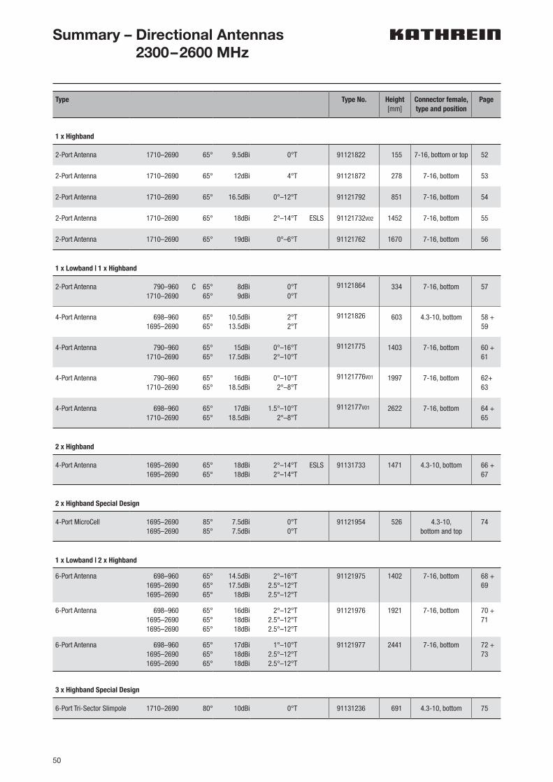
50
Type Type No. Height[mm]
Connector female,type and position
Page
1 x Highband
2-Port Antenna 1710–2690 65° 9.5dBi 0°T 91121822 155 7-16, bottom or top 52
2-Port Antenna 1710–2690 65° 12dBi 4°T 91121872 278 7-16, bottom 53
2-Port Antenna 1710–2690 65° 16.5dBi 0°–12°T 91121792 851 7-16, bottom 54
2-Port Antenna 1710–2690 65° 18dBi 2°–14°T ESLS 91121732V02 1452 7-16, bottom 55
2-Port Antenna 1710–2690 65° 19dBi 0°–6°T 91121762 1670 7-16, bottom 56
1 x Lowband | 1 x Highband
2-Port Antenna 790–9601710–2690
C 65°65°
8dBi9dBi
0°T0°T
91121864 334 7-16, bottom 57
4-Port Antenna 698–9601695–2690
65°65°
10.5dBi13.5dBi
2°T2°T
91121826 603 4.3-10, bottom 58 +59
4-Port Antenna 790–9601710–2690
65°65°
15dBi17.5dBi
0°–16°T2°–10°T
91121775 1403 7-16, bottom 60 +61
4-Port Antenna 790–9601710–2690
65°65°
16dBi18.5dBi
0°–10°T2°–8°T
91121776V01 1997 7-16, bottom 62+63
4-Port Antenna 698–9601710–2690
65°65°
17dBi18.5dBi
1.5°–10°T2°–8°T
9112177V01 2622 7-16, bottom 64 +65
2 x Highband
4-Port Antenna 1695–26901695–2690
65°65°
18dBi18dBi
2°–14°T2°–14°T
ESLS 91131733 1471 4.3-10, bottom 66 +67
2 x Highband Special Design
4-Port MicroCell 1695–26901695–2690
85°85°
7.5dBi7.5dBi
0°T0°T
91121954 526 4.3-10, bottom and top
74
1 x Lowband | 2 x Highband
6-Port Antenna 698–9601695–26901695–2690
65°65°65°
14.5dBi17.5dBi
18dBi
2°–16°T2.5°–12°T2.5°–12°T
91121975 1402 7-16, bottom 68 +69
6-Port Antenna 698–9601695–26901695–2690
65°65°65°
16dBi18dBi18dBi
2°–12°T2.5°–12°T2.5°–12°T
91121976 1921 7-16, bottom 70 +71
6-Port Antenna 698–9601695–26901695–2690
65°65°65°
17dBi18dBi18dBi
1°–10°T2.5°–12°T2.5°–12°T
91121977 2441 7-16, bottom 72 +73
3 x Highband Special Design
6-Port Tri-Sector Slimpole 1710–2690 80° 10dBi 0°T 91131236 691 4.3-10, bottom 75
Summary – Directional Antennas 2300–2600 MHz
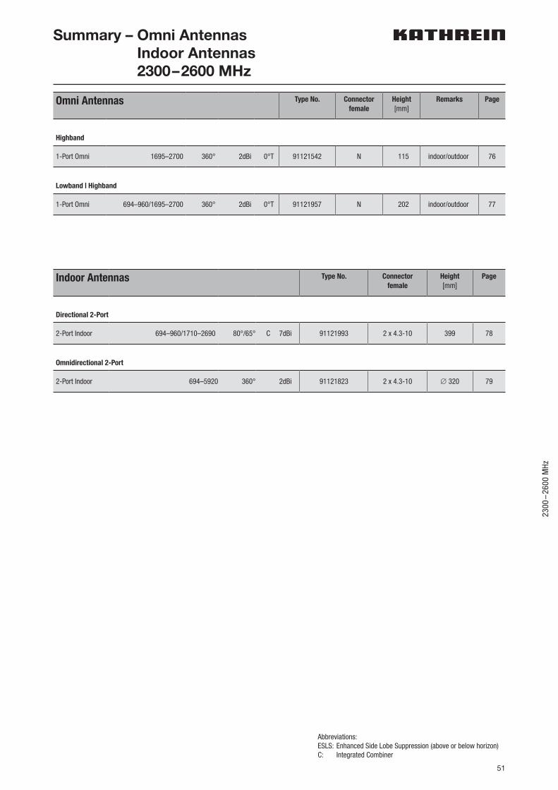
51
2300
–26
00 M
Hz
Omni Antennas Type No. Connectorfemale
Height[mm]
Remarks Page
Highband
1-Port Omni 1695–2700 360° 2dBi 0°T 91121542 N 115 indoor/outdoor 76
Lowband | Highband
1-Port Omni 694–960/1695–2700 360° 2dBi 0°T 91121957 N 202 indoor/outdoor 77
Abbreviations:ESLS: Enhanced Side Lobe Suppression (above or below horizon) C: Integrated Combiner
Summary – Omni Antennas Indoor Antennas 2300–2600 MHz
Indoor Antennas Type No. Connectorfemale
Height[mm]
Page
Directional 2-Port
2-Port Indoor 694–960/1710–2690 80°/65° C 7dBi 91121993 2 x 4.3-10 399 78
Omnidirectional 2-Port
2-Port Indoor 694–5920 360° 2dBi 91121823 2 x 4.3-10 ∅ 320 79
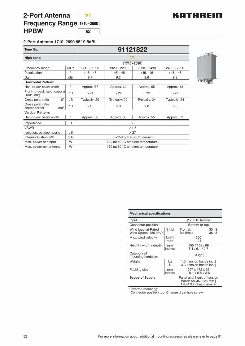
52 For more information about additional mounting accessories please refer to page 91
2-Port AntennaFrequency RangeHPBW
1710–2690
65°
Y1
2-Port Antenna 1710–2690 65° 9.5dBi
Type No. 91121822High band Y1
1710–2690Frequency range MHz 1710 – 1990 1920 – 2200 2200 – 2490 2490 – 2690Polarization ° +45, –45 +45, –45 +45, –45 +45, –45Gain dBi 8.7 9.2 9.6 9.8Horizontal Pattern:Half-power beam width ° Approx. 67 Approx. 62 Approx. 55 Approx. 53Front-to-back ratio, copolar(180°±30°) dB > 24 > 24 > 22 > 22
Cross polar ratio 0° dB Typically: 20 Typically: 20 Typically: 24 Typically: 24Cross polar ratiosector corner ±60° dB > 10 > 9 > 8 > 8
Vertical Pattern:Half-power beam width ° Approx. 66 Approx. 60 Approx. 55 Approx. 53
Impedance Ω 50VSWR < 1.5Isolation, between ports dB > 27Intermodulation IM3 dBc < –150 (2 x 43 dBm carrier)Max. power per input W 100 (at 50 °C ambient temperature)
Max. power per antenna W 150 (at 50 °C ambient temperature)
Mechanical specifications
Input 2 x 7-16 femaleConnector position * Bottom or topWind load (at Rated Wind Speed: 150 km/h)
N | lbf Frontal: 35 | 8Maximal: 35 | 8
Max. wind velocity km/hmph
200124
Height / width / depth mminches
155 / 155 / 696.1 / 6.1 / 2.7
Category of mounting hardware L (Light)
Weight kglb
1.5 (tension bands incl.)3.3 (tension bands incl.)
Packing size mminches
257 x 172 x 9210.1 x 6.8 x 3.6
Scope of Supply Panel and 1 unit of tension bands for 45–125 mm |1.8–4.9 inches diameter
* Inverted mounting: Connector position top: Change drain hole screw
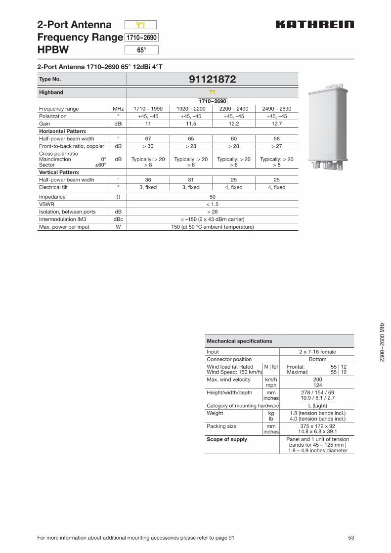
53
2300
–26
00 M
Hz
For more information about additional mounting accessories please refer to page 91
2-Port AntennaFrequency RangeHPBW
1710–2690
65°
Y1
2-Port Antenna 1710–2690 65° 12dBi 4°T
Type No. 91121872Highband Y1
1710–2690Frequency range MHz 1710 – 1990 1920 – 2200 2200 – 2490 2490 – 2690Polarization ° +45, –45 +45, –45 +45, –45 +45, –45Gain dBi 11 11.5 12.2 12.7Horizontal Pattern:Half-power beam width ° 67 65 60 58Front-to-back ratio, copolar dB > 30 > 28 > 28 > 27Cross polar ratio Maindirection 0°Sector ±60°
dB Typically: > 20> 8
Typically: > 20> 8
Typically: > 20> 8
Typically: > 20> 8
Vertical Pattern:Half-power beam width ° 36 31 25 25Electrical tilt ° 3, fixed 3, fixed 4, fixed 4, fixed
Impedance Ω 50VSWR < 1.5Isolation, between ports dB > 28Intermodulation IM3 dBc < –150 (2 x 43 dBm carrier)
Max. power per input W 150 (at 50 °C ambient temperature)
Mechanical specifications
Input 2 x 7-16 femaleConnector position BottomWind load (at Rated Wind Speed: 150 km/h)
N | lbf Frontal: 55 | 12Maximal: 55 | 12
Max. wind velocity km/hmph
200124
Height/width/depth mminches
278 / 154 / 6910.9 / 6.1 / 2.7
Category of mounting hardware L (Light)Weight kg
lb1.8 (tension bands incl.)4.0 (tension bands incl.)
Packing size mminches
375 x 172 x 9214.8 x 6.8 x 39.1
Scope of supply Panel and 1 unit of tension bands for 45 – 125 mm | 1.8 – 4.9 inches diameter
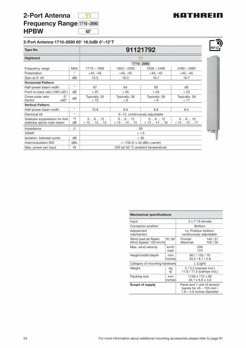
54 For more information about additional mounting accessories please refer to page 91
2-Port AntennaFrequency RangeHPBW
1710–2690
65°
Y1
2-Port Antenna 1710–2690 65° 16.5dBi 0°–12°T
Type No. 91121792Highband Y1
1710–2690Frequency range MHz 1710 – 1990 1920 – 2200 2200 – 2490 2490 – 2690Polarization ° +45, –45 +45, –45 +45, –45 +45, –45Gain at 0° tilt dBi 15.5 16.3 16.7 16.7Horizontal Pattern:Half-power beam width ° 67 64 60 60Front-to-back ratio (180°±30°) dB > 25 > 25 > 23 > 23Cross polar ratio 0°Sector ±60° dB Typically: 25
> 10Typically: 28
> 8Typically: 28
> 8Typically: 28
> 11Vertical Pattern:Half-power beam width ° 10.8 9.9 8.8 8.4Electrical tilt ° 0–12, continuously adjustableSidelobe suppression for first sidelobe above main beam
°TdB
0 ... 6 ... 12≥ 12 ... 13 ... 15
0 ... 6 ... 12≥ 13 ... 14 ... 15
0 ... 6 ... 12≥ 13 ... 14 ... 16
0 ... 6 ... 12≥ 15 ... 15 ... 17
Impedance Ω 50VSWR < 1.5Isolation, between ports dB > 30Intermodulation IM3 dBc < –150 (2 x 43 dBm carrier)Max. power per input W 250 (at 50 °C ambient temperature)
Mechanical specifications
Input 2 x 7-16 femaleConnector position BottomAdjustmentmechanism
1x, Position bottomcontinuously adjustable
Wind load (at Rated Wind Speed: 150 km/h)
N | lbf Frontal: 140 | 31Maximal: 155 | 35
Max. wind velocity km/hmph
200124
Height/width/depth mminches
851 / 155 / 7033.5 / 6.1 / 2.8
Category of mounting hardware L (Light)Weight kg
lb5 / 5.2 (clamps incl.)
11.0 / 11.5 (clamps incl.)
Packing size mminches
1146 x 172 x 9245.1 x 6.8 x 3.6
Scope of supply Panel and 1 unit of tension bands for 45 – 125 mm | 1.8 – 4.9 inches diameter
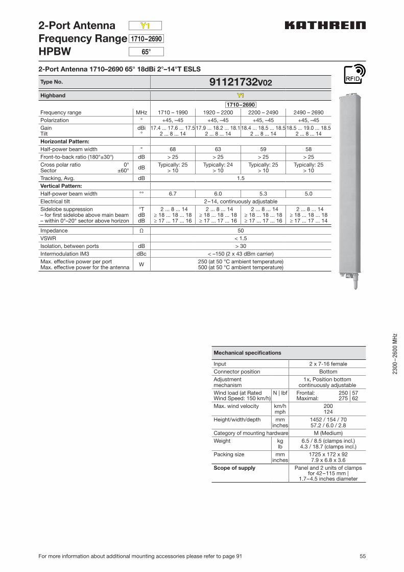
55
2300
–26
00 M
Hz
For more information about additional mounting accessories please refer to page 91
2-Port AntennaFrequency RangeHPBW
1710–2690
65°
Y1
2-Port Antenna 1710–2690 65° 18dBi 2°–14°T ESLS
Type No. 91121732V02Highband Y1
1710–2690Frequency range MHz 1710 – 1990 1920 – 2200 2200 – 2490 2490 – 2690Polarization ° +45, –45 +45, –45 +45, –45 +45, –45GainTilt
dBi°
17.4 ... 17.6 ... 17.52 ... 8 ... 14
17.9 ... 18.2 ... 18.12 ... 8 ... 14
18.4 ... 18.5 ... 18.52 ... 8 ... 14
18.5 ... 19.0 ... 18.52 ... 8 ... 14
Horizontal Pattern:Half-power beam width ° 68 63 59 58Front-to-back ratio (180°±30°) dB > 25 > 25 > 25 > 25Cross polar ratio 0°Sector ±60° dB Typically: 25
> 10Typically: 24
> 10Typically: 25
> 10Typically: 25
> 10Tracking, Avg. dB 1.5Vertical Pattern:Half-power beam width °° 6.7 6.0 5.3 5.0Electrical tilt 2–14, continuously adjustableSidelobe suppression– for first sidelobe above main beam– within 0°–20° sector above horizon
°TdBdB
2 ... 8 ... 14≥ 18 ... 18 ... 18≥ 17 ... 17 ... 16
2 ... 8 ... 14≥ 18 ... 18 ... 18≥ 17 ... 17 ... 16
2 ... 8 ... 14≥ 18 ... 18 ... 18≥ 17 ... 17 ... 16
2 ... 8 ... 14≥ 18 ... 18 ... 18≥ 17 ... 17 ... 14
Impedance Ω 50VSWR < 1.5Isolation, between ports dB > 30Intermodulation IM3 dBc < –150 (2 x 43 dBm carrier)Max. effective power per portMax. effective power for the antenna W 250 (at 50 °C ambient temperature)
500 (at 50 °C ambient temperature)
Mechanical specifications
Input 2 x 7-16 femaleConnector position BottomAdjustmentmechanism
1x, Position bottomcontinuously adjustable
Wind load (at Rated Wind Speed: 150 km/h)
N | lbf Frontal: 250 | 57Maximal: 275 | 62
Max. wind velocity km/hmph
200124
Height/width/depth mminches
1452 / 154 / 7057.2 / 6.0 / 2.8
Category of mounting hardware M (Medium)Weight kg
lb6.5 / 8.5 (clamps incl.)4.3 / 18.7 (clamps incl.)
Packing size mminches
1725 x 172 x 927.9 x 6.8 x 3.6
Scope of supply Panel and 2 units of clamps for 42–115 mm |
1.7–4.5 inches diameter
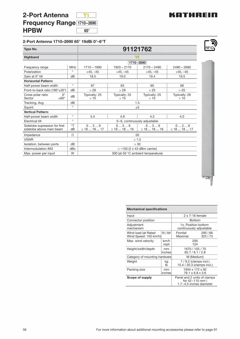
56 For more information about additional mounting accessories please refer to page 91
2-Port AntennaFrequency RangeHPBW
1710–2690
65°
Y1
2-Port Antenna 1710–2690 65° 19dBi 0°–6°T
Type No. 91121762Highband Y1
1710–2690Frequency range MHz 1710 – 1990 1920 – 2170 2170 – 2490 2490 – 2690Polarization ° +45, –45 +45, –45 +45, –45 +45, –45Gain at 0° tilt dB 18.5 19.0 19.4 19.5Horizontal Pattern:Half-power beam width ° 67 63 60 58Front-to-back ratio (180°±30°) dB > 28 > 28 > 25 > 25Cross polar ratio 0°Sector ±60° dB Typically: 25
> 10Typically: 25
> 10Typically: 25
> 10Typically: 28
> 10Tracking, Avg. dB 1.5Squint ° ±3Vertical Pattern:Half-power beam width ° 5.4 4.9 4.3 4.0Electrical tilt ° 0–6, continuously adjustableSidelobe supression for first sidelobe above main beam
°TdB
0 ... 3 ... 6≥ 18 ... 18 ... 17
0 ... 3 ... 6≥ 18 ... 18 ... 16
0 ... 3 ... 6≥ 18 ... 18 ... 16
0 ... 3 ... 6≥ 18 ... 18 ... 17
Impedance Ω 50VSWR < 1.5Isolation, between ports dB > 30Intermodulation IM3 dBc < –150 (2 x 43 dBm carrier)Max. power per input W 300 (at 50 °C ambient temperature)
Mechanical specifications
Input 2 x 7-16 femaleConnector position BottomAdjustmentmechanism
1x, Position bottomcontinuously adjustable
Wind load (at Rated Wind Speed: 150 km/h)
N | lbf Frontal: 295 | 66Maximal: 325 | 73
Max. wind velocity km/hmph
200124
Height/width/depth mminches
1670 / 155 / 7065.7 / 6.1 / 2.8
Category of mounting hardware M (Medium)Weight kg
lb7 / 9.2 (clamps incl.)
15.4 / 20.3 (clamps incl.)Packing size mm
inches1934 x 172 x 9276.1 x 6.8 x 3.6
Scope of supply Panel and 2 units of clamps for 42–115 mm |
1.7–4.5 inches diameter
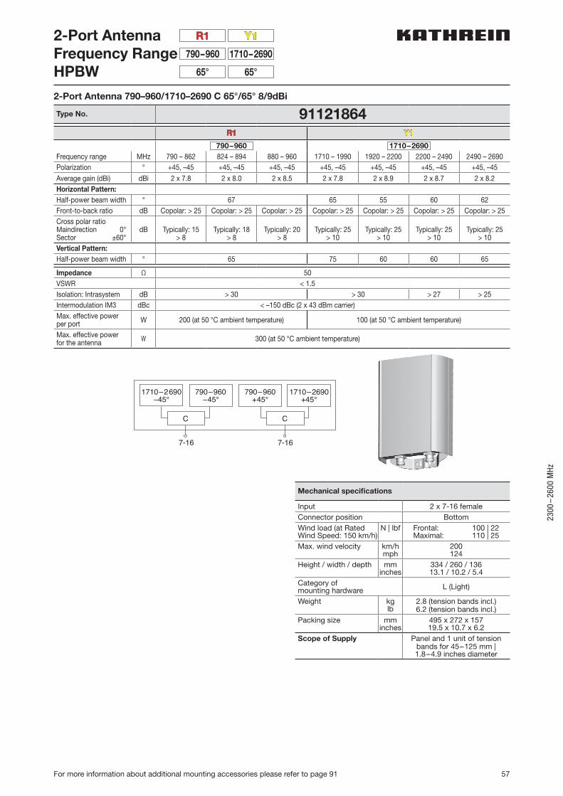
57
2300
–26
00 M
Hz
For more information about additional mounting accessories please refer to page 91
C C
61-761-7
790–960+45°
1710–2690–45°
790–960–45°
1710–2690+45°
2-Port AntennaFrequency RangeHPBW
Y1R1
1710–2690790–960
65°65°
Mechanical specifications
Input 2 x 7-16 femaleConnector position BottomWind load (at Rated Wind Speed: 150 km/h)
N | lbf Frontal: 100 | 22Maximal: 110 | 25
Max. wind velocity km/hmph
200124
Height / width / depth mminches
334 / 260 / 13613.1 / 10.2 / 5.4
Category of mounting hardware L (Light)
Weight kglb
2.8 (tension bands incl.)6.2 (tension bands incl.)
Packing size mminches
495 x 272 x 15719.5 x 10.7 x 6.2
Scope of Supply Panel and 1 unit of tension bands for 45–125 mm |1.8–4.9 inches diameter
2-Port Antenna 790–960/1710–2690 C 65°/65° 8/9dBi
Type No. 91121864R1 Y1
790–960 1710–2690Frequency range MHz 790 – 862 824 – 894 880 – 960 1710 – 1990 1920 – 2200 2200 – 2490 2490 – 2690Polarization ° +45, –45 +45, –45 +45, –45 +45, –45 +45, –45 +45, –45 +45, –45
Average gain (dBi) dBi 2 x 7.8 2 x 8.0 2 x 8.5 2 x 7.8 2 x 8.9 2 x 8.7 2 x 8.2Horizontal Pattern:Half-power beam width ° 67 65 55 60 62Front-to-back ratio dB Copolar: > 25 Copolar: > 25 Copolar: > 25 Copolar: > 25 Copolar: > 25 Copolar: > 25 Copolar: > 25Cross polar ratioMaindirection 0°Sector ±60°
dB Typically: 15> 8
Typically: 18> 8
Typically: 20> 8
Typically: 25> 10
Typically: 25> 10
Typically: 25> 10
Typically: 25> 10
Vertical Pattern:Half-power beam width ° 65 75 60 60 65
Impedance Ω 50VSWR < 1.5Isolation: Intrasystem dB > 30 > 30 > 27 > 25Intermodulation IM3 dBc < –150 dBc (2 x 43 dBm carrier)Max. effective power per port W 200 (at 50 °C ambient temperature) 100 (at 50 °C ambient temperature)
Max. effective power for the antenna W 300 (at 50 °C ambient temperature)
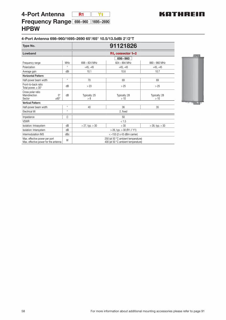
58 For more information about additional mounting accessories please refer to page 91
4-Port AntennaFrequency RangeHPBW
1695–2690
Y1
698–960
R1
4-Port Antenna 698–960/1695–2690 65°/65° 10.5/13.5dBi 2°/2°T
Type No. 91121826Lowband R1, connector 1–2
698–960Frequency range MHz 698 – 824 MHz 824 – 894 MHz 880 – 960 MHzPolarization ° +45, –45 +45, –45 +45, –45Average gain dBi 10.1 10.6 10.7Horizontal Pattern:Half-power beam width ° 70 69 69Front-to-back ratioTotal power, ± 30° dB > 23 > 25 > 25
Cross polar ratioMaindirection 0°Sector ±60°
dB Typically: 25> 8
Typically: 28> 10
Typically: 28> 10
Vertical Pattern:Half-power beam width ° 40 36 35Electrical tilt ° 2, fixed
Impedance Ω 50VSWR < 1.5Isolation: Intrasystem dB > 27, typ. > 30 > 30 > 28, typ. > 30Isolation: Intersystem dB > 26, typ. > 30 (R1 // Y1)Intermodulation IM3 dBc < –153 (2 x 43 dBm carrier)Max. effective power per portMax. effective power for the antenna W 250 (at 50 °C ambient temperature)
400 (at 50 °C ambient temperature)
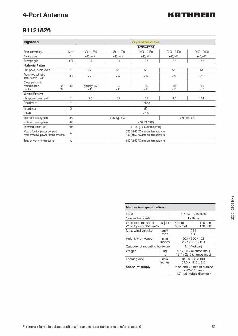
59
2300
–26
00 M
Hz
For more information about additional mounting accessories please refer to page 91
4-Port Antenna
91121826
Highband Y1, connector 3–4
1695–2690Frequency range MHz 1695 – 1880 1850 – 1990 1920 – 2180 2200 – 2490 2490 – 2690Polarization ° +45, –45 +45, –45 +45, –45 +45, –45 +45, –45Average gain dBi 13.1 13.7 13.7 13.8 13.6Horizontal Pattern:Half-power beam width ° 62 55 55 55 68Front-to-back ratioTotal power, ± 30° dB > 26 > 27 > 27 > 27 > 25
Cross polar ratioMaindirection 0°Sector ±60°
dB Typically: 25> 10
> 28> 10
28> 10
25> 10
28> 10
Vertical Pattern:Half-power beam width ° 17.6 16.7 15.9 14.5 12.4Electrical tilt ° 2, fixed
Impedance Ω 50VSWR < 1.5Isolation: Intrasystem dB > 26, typ. > 31 > 30, typ. > 31Isolation: Intersystem dB > 30 (Y1 // R1)Intermodulation IM3 dBc < –153 (2 x 43 dBm carrier)Max. effective power per portMax. effective power for the antenna W 200 (at 50 °C ambient temperature)
400 (at 50 °C ambient temperature)
Total power for the antenna W 800 (at 50 °C ambient temperature)
Mechanical specifications
Input 4 x 4.3-10 femaleConnector position BottomWind load (at Rated Wind Speed: 150 km/h)
N | lbf Frontal: 110 | 25Maximal: 170 | 38
Max. wind velocity km/hmph
241150
Height/width/depth mminches
603 / 300 / 15223.7 / 11.8 / 6.0
Category of mounting hardware M (Medium)Weight kg
lb8.5 / 10.7 (clamps incl.)18.7 / 23.6 (clamps incl.)
Packing size mminches
845 x 325 x 19333.3 x 12.8 x 7.6
Scope of supply Panel and 2 units of clamps for 42–115 mm |
1.7–4.5 inches diameter
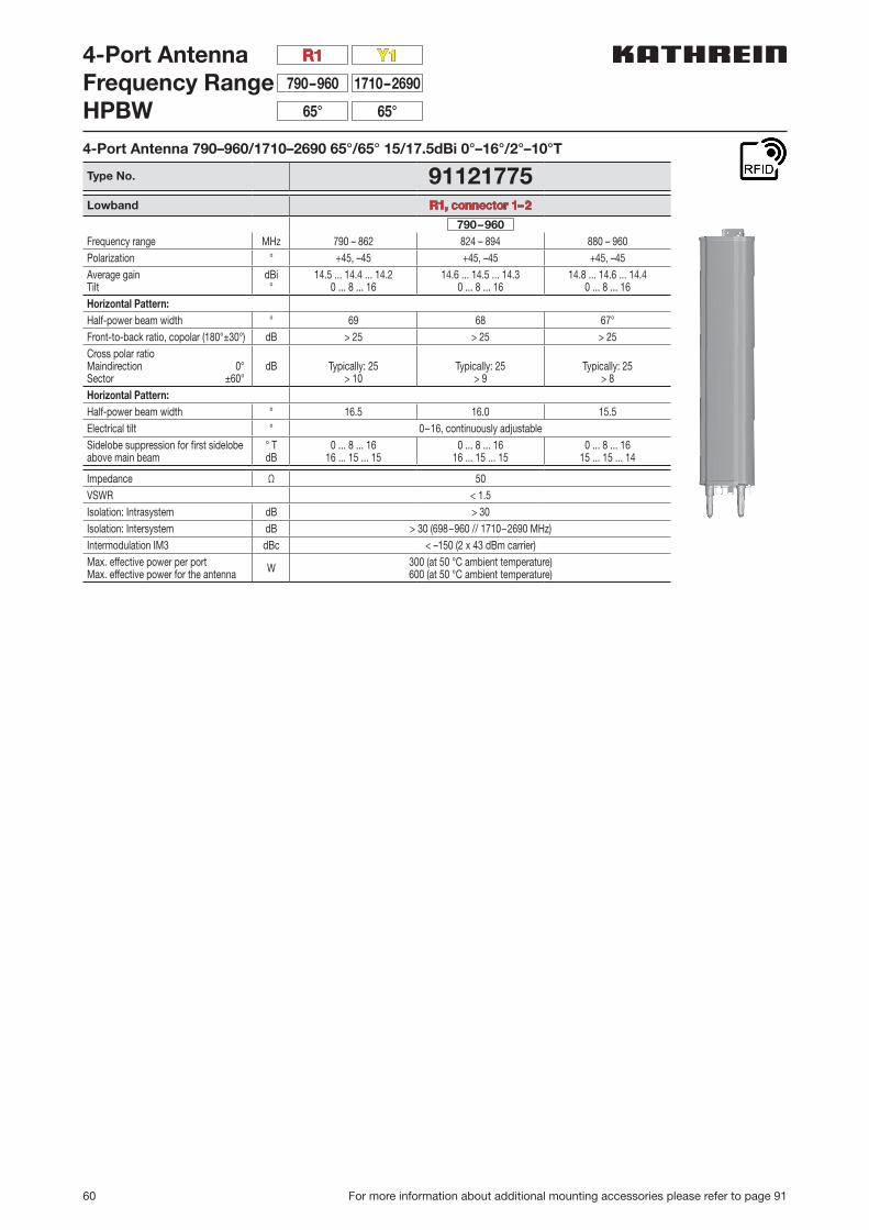
60 For more information about additional mounting accessories please refer to page 91
4-Port AntennaFrequency RangeHPBW
1710–2690
Y1
790–960
R1
65°65°
4-Port Antenna 790–960/1710–2690 65°/65° 15/17.5dBi 0°–16°/2°–10°T
Type No. 91121775Lowband R1, connector 1–2
790–960Frequency range MHz 790 – 862 824 – 894 880 – 960Polarization ° +45, –45 +45, –45 +45, –45Average gainTilt
dBi°
14.5 ... 14.4 ... 14.20 ... 8 ... 16
14.6 ... 14.5 ... 14.30 ... 8 ... 16
14.8 ... 14.6 ... 14.40 ... 8 ... 16
Horizontal Pattern:Half-power beam width ° 69 68 67°Front-to-back ratio, copolar (180°±30°) dB > 25 > 25 > 25Cross polar ratioMaindirection 0°Sector ±60°
dB Typically: 25> 10
Typically: 25> 9
Typically: 25> 8
Horizontal Pattern:Half-power beam width ° 16.5 16.0 15.5Electrical tilt ° 0–16, continuously adjustableSidelobe suppression for first sidelobe above main beam
° TdB
0 ... 8 ... 1616 ... 15 ... 15
0 ... 8 ... 1616 ... 15 ... 15
0 ... 8 ... 1615 ... 15 ... 14
Impedance Ω 50VSWR < 1.5Isolation: Intrasystem dB > 30Isolation: Intersystem dB > 30 (698–960 // 1710–2690 MHz)Intermodulation IM3 dBc < –150 (2 x 43 dBm carrier)Max. effective power per portMax. effective power for the antenna W 300 (at 50 °C ambient temperature)
600 (at 50 °C ambient temperature)
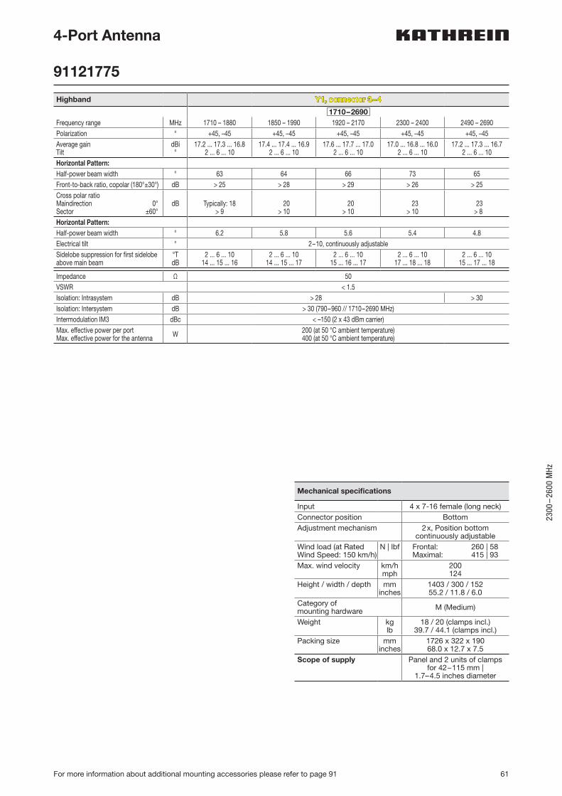
61
2300
–26
00 M
Hz
For more information about additional mounting accessories please refer to page 91
4-Port Antenna
91121775
Highband Y1, connector 3–4
1710–2690Frequency range MHz 1710 – 1880 1850 – 1990 1920 – 2170 2300 – 2400 2490 – 2690Polarization ° +45, –45 +45, –45 +45, –45 +45, –45 +45, –45Average gainTilt
dBi°
17.2 ... 17.3 ... 16.82 ... 6 ... 10
17.4 ... 17.4 ... 16.92 ... 6 ... 10
17.6 ... 17.7 ... 17.02 ... 6 ... 10
17.0 ... 16.8 ... 16.02 ... 6 ... 10
17.2 ... 17.3 ... 16.72 ... 6 ... 10
Horizontal Pattern:Half-power beam width ° 63 64 66 73 65Front-to-back ratio, copolar (180°±30°) dB > 25 > 28 > 29 > 26 > 25Cross polar ratioMaindirection 0°Sector ±60°
dB Typically: 18> 9
> 20> 10
20> 10
23> 10
23 > 8
Horizontal Pattern:Half-power beam width ° 6.2 5.8 5.6 5.4 4.8Electrical tilt ° 2–10, continuously adjustableSidelobe suppression for first sidelobe above main beam
°TdB
2 ... 6 ... 1014 ... 15 ... 16
2 ... 6 ... 1014 ... 15 ... 17
2 ... 6 ... 1015 ... 16 ... 17
2 ... 6 ... 1017 ... 18 ... 18
2 ... 6 ... 1015 ... 17 ... 18
Impedance Ω 50VSWR < 1.5Isolation: Intrasystem dB > 28 > 30Isolation: Intersystem dB > 30 (790–960 // 1710–2690 MHz)Intermodulation IM3 dBc < –150 (2 x 43 dBm carrier)Max. effective power per portMax. effective power for the antenna W 200 (at 50 °C ambient temperature)
400 (at 50 °C ambient temperature)
Mechanical specifications
Input 4 x 7-16 female (long neck)Connector position BottomAdjustment mechanism 2x, Position bottom
continuously adjustableWind load (at Rated Wind Speed: 150 km/h)
N | lbf Frontal: 260 | 58Maximal: 415 | 93
Max. wind velocity km/hmph
200124
Height / width / depth mminches
1403 / 300 / 15255.2 / 11.8 / 6.0
Category of mounting hardware M (Medium)
Weight kglb
18 / 20 (clamps incl.)39.7 / 44.1 (clamps incl.)
Packing size mminches
1726 x 322 x 19068.0 x 12.7 x 7.5
Scope of supply Panel and 2 units of clamps for 42–115 mm |
1.7–4.5 inches diameter

62 For more information about additional mounting accessories please refer to page 91
4-Port Antenna 790–960/1710–2690 65°/65° 16/18.5dBi 0°–10°/2°–8°T
Type No. 91121776V01Lowband R1, connector 1–2
790–960Frequency Range MHz 790 – 862 824 – 894 880 – 960Gain at mid Tilt dBi 16.1 16.2 16.2Gain over all Tilts dBi 15.9 ± 0.3 16.1 ± 0.2 16.1 ± 0.3Horizontal Pattern:Azimuth Beamwidth ° 69 ± 0.9 68 ± 1.2 67 ± 0.6Front-to-Back Ratio,Total Power, ± 30° dB > 23 > 25 > 26
Cross Polar Discriminationat Boresight dB > 23 > 23 > 20
Cross Polar Discriminationover Sector dB > 9.5 > 10.0 > 11.0
Vertical Pattern:Elevation Beamwidth ° 10.1 ± 0.4 9.9 ± 0.3 9.5 ± 0.4Electrical Downtiltcontinuously adjustable ° 0.0 – 10.0
Tilt Accuracy ° < 0.5 < 0.5 < 0.6First Upper Side Lobe Suppression dB > 16 > 18 > 16
Upper Side Lobe Suppression, 20° Sector above Main Beam
dB > 16 > 18 > 16
Cross Polar Isolation dB > 30Port to Port Isolation dB > 30 (R1 // Y1)Max. Effective Powerper Port W 400 (at 50 °C ambient temperature)
Max. Effective PowerPort 1–2 W 800 (at 50 °C ambient temperature)
Values based on NGMN-P-BASTA (version 9.6) requirements.
4-Port AntennaFrequency RangeHPBW
1710–2690
Y1
790–960
R1
65°65°

63
2300
–26
00 M
Hz
For more information about additional mounting accessories please refer to page 91
Highband Y1, connector 3–4
1710–2690Frequency Range MHz 1710 – 1880 1850 – 1990 1920 – 2170 2300 – 2400 2490 – 2690Gain at mid Tilt dBi 18.2 18.5 18.8 18.8 18.7Gain over all Tilts dBi 18.1 ± 0.5 18.4 ± 0.2 18.7 ± 0.5 18.7 ± 0.6 18.5 ± 0.3Horizontal Pattern:Azimuth Beamwidth ° 64 ± 5.4 63 ± 2.7 61 ± 3.6 62 ± 5.7 64 ± 3.4Front-to-Back Ratio,Total Power, ± 30° dB > 25 > 26 > 27 > 26 > 25
Cross Polar Discriminationat Boresight dB > 14 > 19 > 20 > 18 > 20
Cross Polar Discriminationover Sector dB > 8.0 > 9.5 > 10.0 > 10.0 > 11.5
Vertical Pattern:Elevation Beamwidth ° 5.0 ± 0.3 4.7 ± 0.2 4.4 ± 0.3 3.8 ± 0.2 3.5 ± 0.2Electrical Downtiltcontinuously adjustable ° 2.0 – 8.0
Tilt Accuracy ° < 0.2 < 0.2 < 0.3 < 0.2 < 0.3First Upper Side Lobe Suppression dB > 17 > 18 > 19 > 20 > 20
Upper Side Lobe Suppression, 20° Sector above Main Beam
dB > 15 > 16 > 16 > 15 > 17
Cross Polar Isolation dB > 28Port to Port Isolation dB > 30 (R1 // Y1)Max. Effective Powerper Port W 200 (at 50 °C ambient temperature)
Max. Effective PowerPort 3–4 W 400 (at 50 °C ambient temperature)
Values based on NGMN-P-BASTA (version 9.6) requirements.
Electrical specifications, all systems
Impedance Ω 50VSWR < 1.5Return Loss dB > 14Interband Isolation dB > 30Passive Intermodulation dBc < –150 (2 x 43 dBm carrier)Polarization ° +45, –45Max. Effective Powerfor the Antenna W 900 (at 50 °C ambient
temperature)Values based on NGMN-P-BASTA (version 9.6) requirements.
4-Port Antenna
91121776V01
Mechanical specifications
Input 4 x 7-16 female long neckConnector Position bottomAdjustment Mechanism 2x, Position bottom
continuously adjustableWind load (at Rated Wind Speed: 150 km/h)
N | lbf Frontal: 390 | 88Maximal: 620 | 139
Max. Wind Velocity km/hmph
200124
Height / Width / Depth mminches
1997 / 300 / 15278.6 / 11.8 / 6.0
Category of Mounting Hardware M (Medium)
Weight kglb
24.0 / 26.2 (clamps incl.)52.9 / 57.8 (clamps incl.)
Packing Size mminches
2316 / 322 / 19091.2 / 12.7 / 7.5
Scope of Supply Panel and 2 units of clamps for 42–115 mm |
1.7–4.5 inches diameter
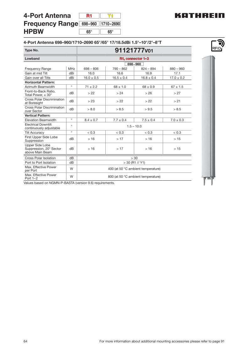
64 For more information about additional mounting accessories please refer to page 91
4-Port AntennaFrequency RangeHPBW
1710–2690
Y1
698–960
R1
65°65°
4-Port Antenna 698–960/1710–2690 65°/65° 17/18.5dBi 1.5°–10°/2°–8°T
Type No. 91121777V01Lowband R1, connector 1–2
698–960Frequency Range MHz 698 – 806 790 – 862 824 – 894 880 – 960Gain at mid Tilt dBi 16.0 16.6 16.9 17.1Gain over all Tilts dBi 16.0 ± 0.5 16.5 ± 0.4 16.8 ± 0.4 17.0 ± 0.2Horizontal Pattern:Azimuth Beamwidth ° 71 ± 2.2 68 ± 1.0 68 ± 0.9 67 ± 1.5Front-to-Back Ratio,Total Power, ± 30° dB > 22 > 24 > 26 > 27
Cross Polar Discriminationat Boresight dB > 23 > 22 > 22 > 21
Cross Polar Discriminationover Sector dB > 8.0 > 8.5 > 9.5 > 8.5
Vertical Pattern:Elevation Beamwidth ° 8.4 ± 0.7 7.7 ± 0.4 7.5 ± 0.4 7.0 ± 0.3Electrical Downtiltcontinuously adjustable ° 1.5 – 10.0
Tilt Accuracy ° < 0.3 < 0.3 < 0.3 < 0.3First Upper Side Lobe Suppression dB > 16 > 17 > 16 > 15
Upper Side Lobe Suppression, 20° Sector above Main Beam
dB > 16 > 17 > 16 > 15
Cross Polar Isolation dB > 30Port to Port Isolation dB > 30 (R1 // Y1)Max. Effective Powerper Port W 400 (at 50 °C ambient temperature)
Max. Effective PowerPort 1–2 W 800 (at 50 °C ambient temperature)
Values based on NGMN-P-BASTA (version 9.6) requirements.
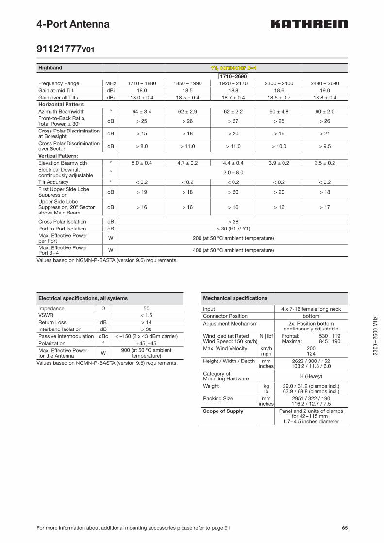
65
2300
–26
00 M
Hz
For more information about additional mounting accessories please refer to page 91
Highband Y1, connector 3–4
1710–2690Frequency Range MHz 1710 – 1880 1850 – 1990 1920 – 2170 2300 – 2400 2490 – 2690Gain at mid Tilt dBi 18.0 18.5 18.8 18.6 19.0Gain over all Tilts dBi 18.0 ± 0.4 18.5 ± 0.4 18.7 ± 0.4 18.5 ± 0.7 18.8 ± 0.4Horizontal Pattern:Azimuth Beamwidth ° 64 ± 3.4 62 ± 2.9 62 ± 2.2 60 ± 4.8 60 ± 2.0Front-to-Back Ratio,Total Power, ± 30° dB > 25 > 26 > 27 > 25 > 26
Cross Polar Discriminationat Boresight dB > 15 > 18 > 20 > 16 > 21
Cross Polar Discriminationover Sector dB > 8.0 > 11.0 > 11.0 > 10.0 > 9.5
Vertical Pattern:Elevation Beamwidth ° 5.0 ± 0.4 4.7 ± 0.2 4.4 ± 0.4 3.9 ± 0.2 3.5 ± 0.2Electrical Downtiltcontinuously adjustable ° 2.0 – 8.0
Tilt Accuracy ° < 0.2 < 0.2 < 0.2 < 0.2 < 0.2First Upper Side Lobe Suppression dB > 19 > 18 > 20 > 20 > 18
Upper Side Lobe Suppression, 20° Sector above Main Beam
dB > 16 > 16 > 16 > 16 > 17
Cross Polar Isolation dB > 28Port to Port Isolation dB > 30 (R1 // Y1)Max. Effective Powerper Port W 200 (at 50 °C ambient temperature)
Max. Effective PowerPort 3–4 W 400 (at 50 °C ambient temperature)
Values based on NGMN-P-BASTA (version 9.6) requirements.
4-Port Antenna
91121777V01
Electrical specifications, all systems
Impedance Ω 50VSWR < 1.5Return Loss dB > 14Interband Isolation dB > 30Passive Intermodulation dBc < –150 (2 x 43 dBm carrier)Polarization ° +45, –45Max. Effective Powerfor the Antenna W 900 (at 50 °C ambient
temperature)Values based on NGMN-P-BASTA (version 9.6) requirements.
Mechanical specifications
Input 4 x 7-16 female long neckConnector Position bottomAdjustment Mechanism 2x, Position bottom
continuously adjustableWind load (at Rated Wind Speed: 150 km/h)
N | lbf Frontal: 530 | 119Maximal: 845 | 190
Max. Wind Velocity km/hmph
200124
Height / Width / Depth mminches
2622 / 300 / 152103.2 / 11.8 / 6.0
Category of Mounting Hardware H (Heavy)
Weight kglb
29.0 / 31.2 (clamps incl.)63.9 / 68.8 (clamps incl.)
Packing Size mminches
2951 / 322 / 190116.2 / 12.7 / 7.5
Scope of Supply Panel and 2 units of clamps for 42–115 mm |
1.7–4.5 inches diameter
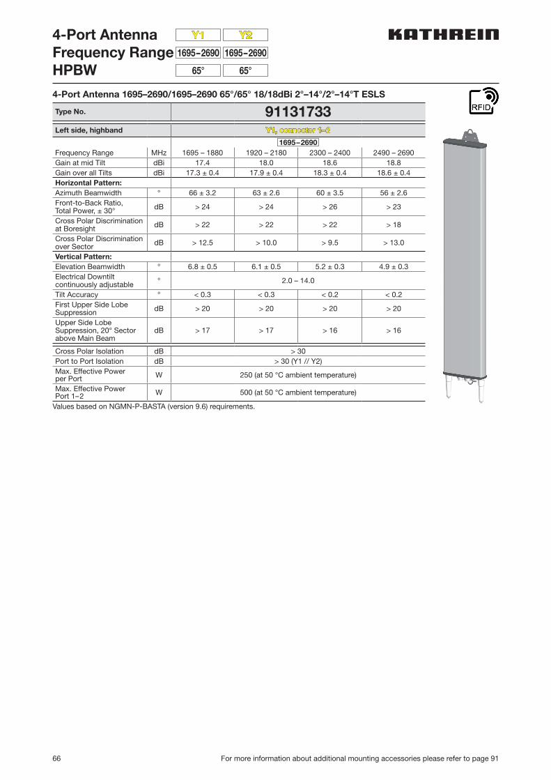
66 For more information about additional mounting accessories please refer to page 91
4-Port AntennaFrequency RangeHPBW
1695–2690
Y2
1695–2690
Y1
65°65°
4-Port Antenna 1695–2690/1695–2690 65°/65° 18/18dBi 2°–14°/2°–14°T ESLS
Type No. 91131733Left side, highband Y1, connector 1–2
1695–2690Frequency Range MHz 1695 – 1880 1920 – 2180 2300 – 2400 2490 – 2690Gain at mid Tilt dBi 17.4 18.0 18.6 18.8Gain over all Tilts dBi 17.3 ± 0.4 17.9 ± 0.4 18.3 ± 0.4 18.6 ± 0.4Horizontal Pattern:Azimuth Beamwidth ° 66 ± 3.2 63 ± 2.6 60 ± 3.5 56 ± 2.6Front-to-Back Ratio,Total Power, ± 30° dB > 24 > 24 > 26 > 23
Cross Polar Discriminationat Boresight dB > 22 > 22 > 22 > 18
Cross Polar Discriminationover Sector dB > 12.5 > 10.0 > 9.5 > 13.0
Vertical Pattern:Elevation Beamwidth ° 6.8 ± 0.5 6.1 ± 0.5 5.2 ± 0.3 4.9 ± 0.3Electrical Downtiltcontinuously adjustable ° 2.0 – 14.0
Tilt Accuracy ° < 0.3 < 0.3 < 0.2 < 0.2First Upper Side Lobe Suppression dB > 20 > 20 > 20 > 20
Upper Side Lobe Suppression, 20° Sector above Main Beam
dB > 17 > 17 > 16 > 16
Cross Polar Isolation dB > 30Port to Port Isolation dB > 30 (Y1 // Y2)Max. Effective Powerper Port W 250 (at 50 °C ambient temperature)
Max. Effective PowerPort 1–2 W 500 (at 50 °C ambient temperature)
Values based on NGMN-P-BASTA (version 9.6) requirements.
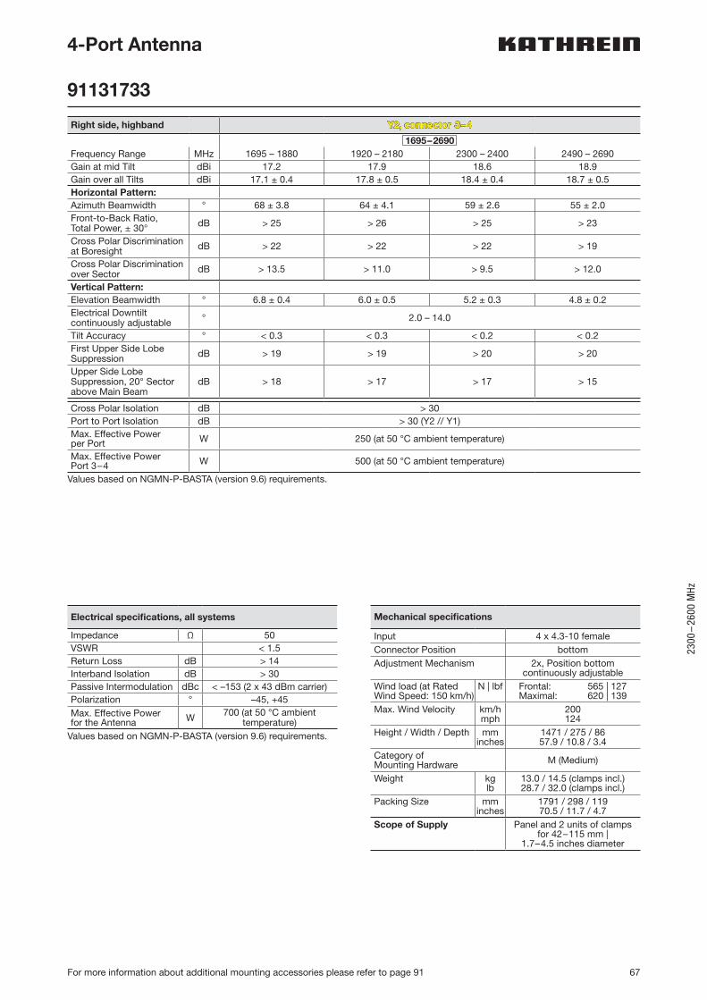
67
2300
–26
00 M
Hz
For more information about additional mounting accessories please refer to page 91
4-Port Antenna
91131733
Right side, highband Y2, connector 3–4
1695–2690Frequency Range MHz 1695 – 1880 1920 – 2180 2300 – 2400 2490 – 2690Gain at mid Tilt dBi 17.2 17.9 18.6 18.9Gain over all Tilts dBi 17.1 ± 0.4 17.8 ± 0.5 18.4 ± 0.4 18.7 ± 0.5Horizontal Pattern:Azimuth Beamwidth ° 68 ± 3.8 64 ± 4.1 59 ± 2.6 55 ± 2.0Front-to-Back Ratio,Total Power, ± 30° dB > 25 > 26 > 25 > 23
Cross Polar Discriminationat Boresight dB > 22 > 22 > 22 > 19
Cross Polar Discriminationover Sector dB > 13.5 > 11.0 > 9.5 > 12.0
Vertical Pattern:Elevation Beamwidth ° 6.8 ± 0.4 6.0 ± 0.5 5.2 ± 0.3 4.8 ± 0.2Electrical Downtiltcontinuously adjustable ° 2.0 – 14.0
Tilt Accuracy ° < 0.3 < 0.3 < 0.2 < 0.2First Upper Side Lobe Suppression dB > 19 > 19 > 20 > 20
Upper Side Lobe Suppression, 20° Sector above Main Beam
dB > 18 > 17 > 17 > 15
Cross Polar Isolation dB > 30Port to Port Isolation dB > 30 (Y2 // Y1)Max. Effective Powerper Port W 250 (at 50 °C ambient temperature)
Max. Effective PowerPort 3–4 W 500 (at 50 °C ambient temperature)
Values based on NGMN-P-BASTA (version 9.6) requirements.
Electrical specifications, all systems
Impedance Ω 50VSWR < 1.5Return Loss dB > 14Interband Isolation dB > 30Passive Intermodulation dBc < –153 (2 x 43 dBm carrier)Polarization ° –45, +45Max. Effective Powerfor the Antenna W 700 (at 50 °C ambient
temperature)Values based on NGMN-P-BASTA (version 9.6) requirements.
Mechanical specifications
Input 4 x 4.3-10 femaleConnector Position bottomAdjustment Mechanism 2x, Position bottom
continuously adjustableWind load (at Rated Wind Speed: 150 km/h)
N | lbf Frontal: 565 | 127Maximal: 620 | 139
Max. Wind Velocity km/hmph
200124
Height / Width / Depth mminches
1471 / 275 / 8657.9 / 10.8 / 3.4
Category of Mounting Hardware M (Medium)
Weight kglb
13.0 / 14.5 (clamps incl.)28.7 / 32.0 (clamps incl.)
Packing Size mminches
1791 / 298 / 11970.5 / 11.7 / 4.7
Scope of Supply Panel and 2 units of clamps for 42–115 mm |
1.7–4.5 inches diameter
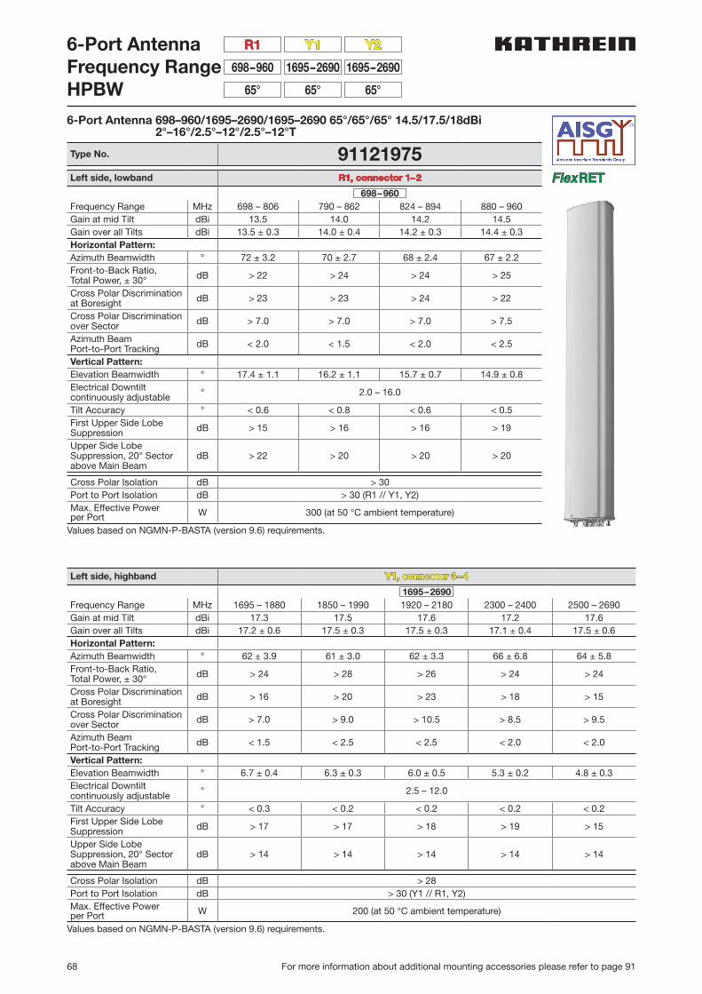
68 For more information about additional mounting accessories please refer to page 91
6-Port AntennaFrequency RangeHPBW
1695–2690698–960 1695–2690
65°65° 65°
Y1 Y2R1
6-Port Antenna 698–960/1695–2690/1695–2690 65°/65°/65° 14.5/17.5/18dBi 2°–16°/2.5°–12°/2.5°–12°T
Type No. 91121975Left side, lowband R1, connector 1–2
698–960Frequency Range MHz 698 – 806 790 – 862 824 – 894 880 – 960Gain at mid Tilt dBi 13.5 14.0 14.2 14.5Gain over all Tilts dBi 13.5 ± 0.3 14.0 ± 0.4 14.2 ± 0.3 14.4 ± 0.3Horizontal Pattern:Azimuth Beamwidth ° 72 ± 3.2 70 ± 2.7 68 ± 2.4 67 ± 2.2Front-to-Back Ratio,Total Power, ± 30° dB > 22 > 24 > 24 > 25
Cross Polar Discriminationat Boresight dB > 23 > 23 > 24 > 22
Cross Polar Discriminationover Sector dB > 7.0 > 7.0 > 7.0 > 7.5
Azimuth Beam Port-to-Port Tracking dB < 2.0 < 1.5 < 2.0 < 2.5
Vertical Pattern:Elevation Beamwidth ° 17.4 ± 1.1 16.2 ± 1.1 15.7 ± 0.7 14.9 ± 0.8Electrical Downtiltcontinuously adjustable ° 2.0 – 16.0
Tilt Accuracy ° < 0.6 < 0.8 < 0.6 < 0.5First Upper Side Lobe Suppression dB > 15 > 16 > 16 > 19
Upper Side Lobe Suppression, 20° Sector above Main Beam
dB > 22 > 20 > 20 > 20
Cross Polar Isolation dB > 30Port to Port Isolation dB > 30 (R1 // Y1, Y2)Max. Effective Powerper Port W 300 (at 50 °C ambient temperature)
Values based on NGMN-P-BASTA (version 9.6) requirements.
Left side, highband Y1, connector 3–4
1695–2690Frequency Range MHz 1695 – 1880 1850 – 1990 1920 – 2180 2300 – 2400 2500 – 2690Gain at mid Tilt dBi 17.3 17.5 17.6 17.2 17.6Gain over all Tilts dBi 17.2 ± 0.6 17.5 ± 0.3 17.5 ± 0.3 17.1 ± 0.4 17.5 ± 0.6Horizontal Pattern:Azimuth Beamwidth ° 62 ± 3.9 61 ± 3.0 62 ± 3.3 66 ± 6.8 64 ± 5.8Front-to-Back Ratio,Total Power, ± 30° dB > 24 > 28 > 26 > 24 > 24
Cross Polar Discriminationat Boresight dB > 16 > 20 > 23 > 18 > 15
Cross Polar Discriminationover Sector dB > 7.0 > 9.0 > 10.5 > 8.5 > 9.5
Azimuth Beam Port-to-Port Tracking dB < 1.5 < 2.5 < 2.5 < 2.0 < 2.0
Vertical Pattern:Elevation Beamwidth ° 6.7 ± 0.4 6.3 ± 0.3 6.0 ± 0.5 5.3 ± 0.2 4.8 ± 0.3Electrical Downtiltcontinuously adjustable ° 2.5 – 12.0
Tilt Accuracy ° < 0.3 < 0.2 < 0.2 < 0.2 < 0.2First Upper Side Lobe Suppression dB > 17 > 17 > 18 > 19 > 15
Upper Side Lobe Suppression, 20° Sector above Main Beam
dB > 14 > 14 > 14 > 14 > 14
Cross Polar Isolation dB > 28Port to Port Isolation dB > 30 (Y1 // R1, Y2)Max. Effective Powerper Port W 200 (at 50 °C ambient temperature)
Values based on NGMN-P-BASTA (version 9.6) requirements.
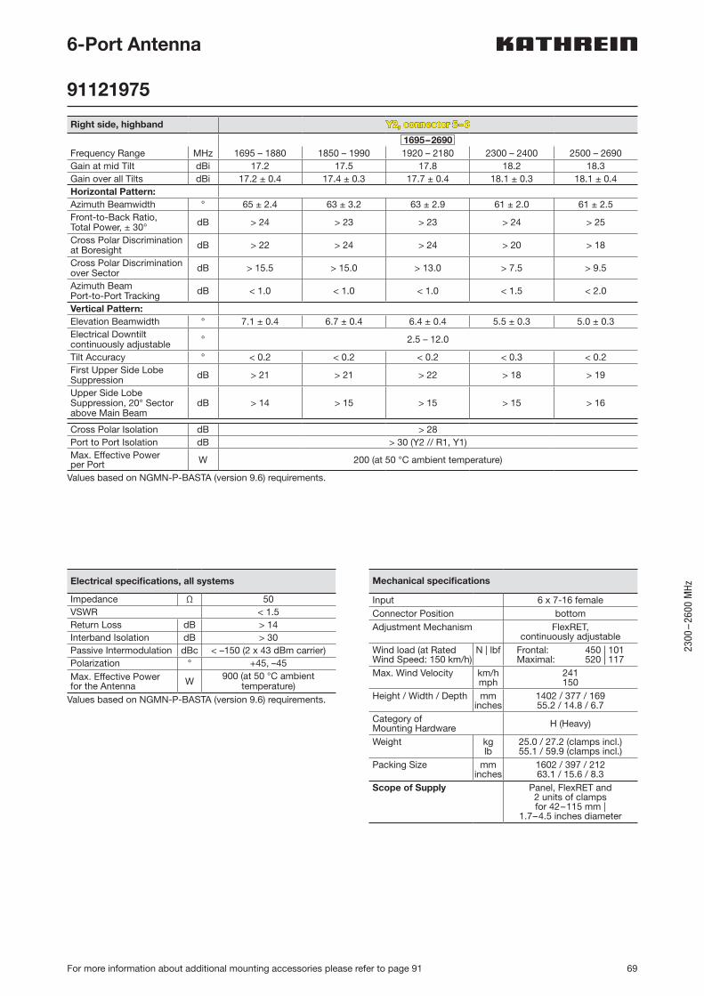
69
2300
–26
00 M
Hz
For more information about additional mounting accessories please refer to page 91
6-Port Antenna
91121975
Right side, highband Y2, connector 5–6
1695–2690Frequency Range MHz 1695 – 1880 1850 – 1990 1920 – 2180 2300 – 2400 2500 – 2690Gain at mid Tilt dBi 17.2 17.5 17.8 18.2 18.3Gain over all Tilts dBi 17.2 ± 0.4 17.4 ± 0.3 17.7 ± 0.4 18.1 ± 0.3 18.1 ± 0.4Horizontal Pattern:Azimuth Beamwidth ° 65 ± 2.4 63 ± 3.2 63 ± 2.9 61 ± 2.0 61 ± 2.5Front-to-Back Ratio,Total Power, ± 30° dB > 24 > 23 > 23 > 24 > 25
Cross Polar Discriminationat Boresight dB > 22 > 24 > 24 > 20 > 18
Cross Polar Discriminationover Sector dB > 15.5 > 15.0 > 13.0 > 7.5 > 9.5
Azimuth Beam Port-to-Port Tracking dB < 1.0 < 1.0 < 1.0 < 1.5 < 2.0
Vertical Pattern:Elevation Beamwidth ° 7.1 ± 0.4 6.7 ± 0.4 6.4 ± 0.4 5.5 ± 0.3 5.0 ± 0.3Electrical Downtiltcontinuously adjustable ° 2.5 – 12.0
Tilt Accuracy ° < 0.2 < 0.2 < 0.2 < 0.3 < 0.2First Upper Side Lobe Suppression dB > 21 > 21 > 22 > 18 > 19
Upper Side Lobe Suppression, 20° Sector above Main Beam
dB > 14 > 15 > 15 > 15 > 16
Cross Polar Isolation dB > 28Port to Port Isolation dB > 30 (Y2 // R1, Y1)Max. Effective Powerper Port W 200 (at 50 °C ambient temperature)
Values based on NGMN-P-BASTA (version 9.6) requirements.
Electrical specifications, all systems
Impedance Ω 50VSWR < 1.5Return Loss dB > 14Interband Isolation dB > 30Passive Intermodulation dBc < –150 (2 x 43 dBm carrier)Polarization ° +45, –45Max. Effective Powerfor the Antenna W 900 (at 50 °C ambient
temperature)Values based on NGMN-P-BASTA (version 9.6) requirements.
Mechanical specifications
Input 6 x 7-16 femaleConnector Position bottomAdjustment Mechanism FlexRET,
continuously adjustableWind load (at Rated Wind Speed: 150 km/h)
N | lbf Frontal: 450 | 101Maximal: 520 | 117
Max. Wind Velocity km/hmph
241150
Height / Width / Depth mminches
1402 / 377 / 16955.2 / 14.8 / 6.7
Category of Mounting Hardware H (Heavy)
Weight kglb
25.0 / 27.2 (clamps incl.)55.1 / 59.9 (clamps incl.)
Packing Size mminches
1602 / 397 / 21263.1 / 15.6 / 8.3
Scope of Supply Panel, FlexRET and 2 units of clamps for 42–115 mm |
1.7–4.5 inches diameter
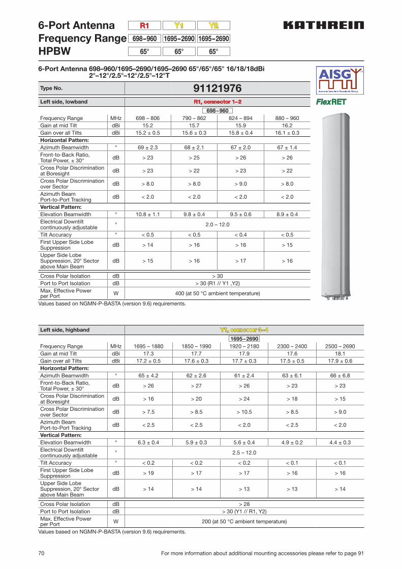
70 For more information about additional mounting accessories please refer to page 91
6-Port AntennaFrequency RangeHPBW
1695–2690698–960 1695–2690
65°65° 65°
Y1 Y2R1
6-Port Antenna 698–960/1695–2690/1695–2690 65°/65°/65° 16/18/18dBi 2°–12°/2.5°–12°/2.5°–12°T
Type No. 91121976Left side, lowband R1, connector 1–2
698–960Frequency Range MHz 698 – 806 790 – 862 824 – 894 880 – 960Gain at mid Tilt dBi 15.2 15.7 15.9 16.2Gain over all Tilts dBi 15.2 ± 0.5 15.6 ± 0.3 15.8 ± 0.4 16.1 ± 0.3Horizontal Pattern:Azimuth Beamwidth ° 69 ± 2.3 68 ± 2.1 67 ± 2.0 67 ± 1.4Front-to-Back Ratio,Total Power, ± 30° dB > 23 > 25 > 26 > 26
Cross Polar Discriminationat Boresight dB > 23 > 22 > 23 > 22
Cross Polar Discriminationover Sector dB > 8.0 > 8.0 > 9.0 > 8.0
Azimuth Beam Port-to-Port Tracking dB < 2.0 < 2.0 < 2.0 < 2.0
Vertical Pattern:Elevation Beamwidth ° 10.8 ± 1.1 9.8 ± 0.4 9.5 ± 0.6 8.9 ± 0.4Electrical Downtiltcontinuously adjustable ° 2.0 – 12.0
Tilt Accuracy ° < 0.5 < 0.5 < 0.4 < 0.5First Upper Side Lobe Suppression dB > 14 > 16 > 16 > 15
Upper Side Lobe Suppression, 20° Sector above Main Beam
dB > 15 > 16 > 17 > 16
Cross Polar Isolation dB > 30Port to Port Isolation dB > 30 (R1 // Y1 ,Y2)Max. Effective Powerper Port W 400 (at 50 °C ambient temperature)
Values based on NGMN-P-BASTA (version 9.6) requirements.
Left side, highband Y1, connector 3–4
1695–2690Frequency Range MHz 1695 – 1880 1850 – 1990 1920 – 2180 2300 – 2400 2500 – 2690Gain at mid Tilt dBi 17.3 17.7 17.9 17.6 18.1Gain over all Tilts dBi 17.2 ± 0.5 17.6 ± 0.3 17.7 ± 0.3 17.5 ± 0.5 17.9 ± 0.6Horizontal Pattern:Azimuth Beamwidth ° 65 ± 4.2 62 ± 2.6 61 ± 2.4 63 ± 6.1 66 ± 6.8Front-to-Back Ratio,Total Power, ± 30° dB > 26 > 27 > 26 > 23 > 23
Cross Polar Discriminationat Boresight dB > 16 > 20 > 24 > 18 > 15
Cross Polar Discriminationover Sector dB > 7.5 > 8.5 > 10.5 > 8.5 > 9.0
Azimuth Beam Port-to-Port Tracking dB < 2.5 < 2.5 < 2.0 < 2.5 < 2.0
Vertical Pattern:Elevation Beamwidth ° 6.3 ± 0.4 5.9 ± 0.3 5.6 ± 0.4 4.9 ± 0.2 4.4 ± 0.3Electrical Downtiltcontinuously adjustable ° 2.5 – 12.0
Tilt Accuracy ° < 0.2 < 0.2 < 0.2 < 0.1 < 0.1First Upper Side Lobe Suppression dB > 19 > 17 > 17 > 16 > 16
Upper Side Lobe Suppression, 20° Sector above Main Beam
dB > 14 > 14 > 13 > 13 > 14
Cross Polar Isolation dB > 28Port to Port Isolation dB > 30 (Y1 // R1, Y2)Max. Effective Powerper Port W 200 (at 50 °C ambient temperature)
Values based on NGMN-P-BASTA (version 9.6) requirements.

71
2300
–26
00 M
Hz
For more information about additional mounting accessories please refer to page 91
6-Port Antenna
91121976
Right side, highband Y2, connector 5–6
1695–2690Frequency Range MHz 1695 – 1880 1850 – 1990 1920 – 2180 2300 – 2400 2500 – 2690Gain at mid Tilt dBi 17.3 17.5 17.8 18.2 18.1Gain over all Tilts dBi 17.3 ± 0.3 17.5 ± 0.3 17.8 ± 0.4 18.1 ± 0.3 17.9 ± 0.6Horizontal Pattern:Azimuth Beamwidth ° 65 ± 2.9 66 ± 2.8 66 ± 2.6 65 ± 1.8 68 ± 4.8Front-to-Back Ratio,Total Power, ± 30° dB > 22 > 24 > 24 > 25 > 26
Cross Polar Discriminationat Boresight dB > 15 > 19 > 18 > 17 > 19
Cross Polar Discriminationover Sector dB > 10.5 > 15.0 > 14.5 > 10.0 > 10.0
Azimuth Beam Port-to-Port Tracking dB < 1.0 < 1.0 < 1.0 < 0.5 < 2.5
Vertical Pattern:Elevation Beamwidth ° 7.1 ± 0.4 6.7 ± 0.3 6.3 ± 0.5 5.6 ± 0.3 5.0 ± 0.3Electrical Downtiltcontinuously adjustable ° 2.5 – 12.0
Tilt Accuracy ° < 0.3 < 0.3 < 0.3 < 0.3 < 0.3First Upper Side Lobe Suppression dB > 19 > 25 > 25 > 19 > 21
Upper Side Lobe Suppression, 20° Sector above Main Beam
dB > 13 > 15 > 17 > 17 > 15
Cross Polar Isolation dB > 28Port to Port Isolation dB > 30 (Y2 // R1, Y1)Max. Effective Powerper Port W 200 (at 50 °C ambient temperature)
Values based on NGMN-P-BASTA (version 9.6) requirements.
Electrical specifications, all systems
Impedance Ω 50VSWR < 1.5Return Loss dB > 14Interband Isolation dB > 30Passive Intermodulation dBc < –150 (2 x 43 dBm carrier)Polarization ° +45, –45Max. Effective Powerfor the Antenna W 900 (at 50 °C ambient
temperature)Values based on NGMN-P-BASTA (version 9.6) requirements.
Mechanical specifications
Input 6 x 7-16 femaleConnector Position bottomAdjustment Mechanism FlexRET,
continuously adjustableWind load (at Rated Wind Speed: 150 km/h)
N | lbf Frontal: 630 | 142Maximal: 730 | 164
Max. Wind Velocity km/hmph
241150
Height / Width / Depth mminches
1921 / 377 / 16975.6 / 14.8 / 6.7
Category of Mounting Hardware H (Heavy)
Weight kglb
30.0 / 32.2 (clamps incl.)66.1 / 70.9 (clamps incl.)
Packing Size mminches
2121 / 397 / 21283.5 / 15.6 / 8.3
Scope of Supply Panel, FlexRET and 2 units of clamps for 42–115 mm |
1.7–4.5 inches diameter
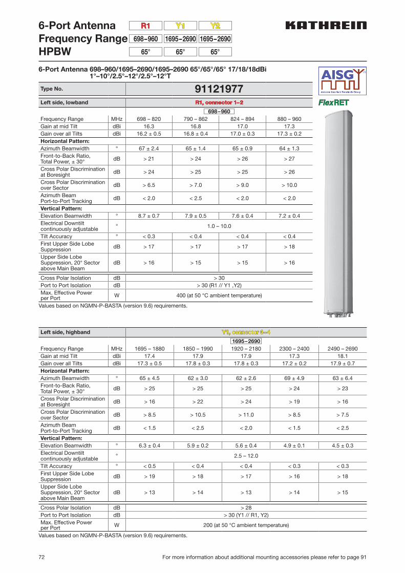
72 For more information about additional mounting accessories please refer to page 91
6-Port AntennaFrequency RangeHPBW
1695–2690698–960 1695–2690
65°65° 65°
Y1 Y2R1
6-Port Antenna 698–960/1695–2690/1695–2690 65°/65°/65° 17/18/18dBi 1°–10°/2.5°–12°/2.5°–12°T
Type No. 91121977Left side, lowband R1, connector 1–2
698–960Frequency Range MHz 698 – 820 790 – 862 824 – 894 880 – 960Gain at mid Tilt dBi 16.3 16.8 17.0 17.3Gain over all Tilts dBi 16.2 ± 0.5 16.8 ± 0.4 17.0 ± 0.3 17.3 ± 0.2Horizontal Pattern:Azimuth Beamwidth ° 67 ± 2.4 65 ± 1.4 65 ± 0.9 64 ± 1.3Front-to-Back Ratio,Total Power, ± 30° dB > 21 > 24 > 26 > 27
Cross Polar Discriminationat Boresight dB > 24 > 25 > 25 > 26
Cross Polar Discriminationover Sector dB > 6.5 > 7.0 > 9.0 > 10.0
Azimuth Beam Port-to-Port Tracking dB < 2.0 < 2.5 < 2.0 < 2.0
Vertical Pattern:Elevation Beamwidth ° 8.7 ± 0.7 7.9 ± 0.5 7.6 ± 0.4 7.2 ± 0.4Electrical Downtiltcontinuously adjustable ° 1.0 – 10.0
Tilt Accuracy ° < 0.3 < 0.4 < 0.4 < 0.4First Upper Side Lobe Suppression dB > 17 > 17 > 17 > 18
Upper Side Lobe Suppression, 20° Sector above Main Beam
dB > 16 > 15 > 15 > 16
Cross Polar Isolation dB > 30Port to Port Isolation dB > 30 (R1 // Y1 ,Y2)Max. Effective Powerper Port W 400 (at 50 °C ambient temperature)
Values based on NGMN-P-BASTA (version 9.6) requirements.
Left side, highband Y1, connector 3–4
1695–2690Frequency Range MHz 1695 – 1880 1850 – 1990 1920 – 2180 2300 – 2400 2490 – 2690Gain at mid Tilt dBi 17.4 17.9 17.9 17.3 18.1Gain over all Tilts dBi 17.3 ± 0.5 17.8 ± 0.3 17.8 ± 0.3 17.2 ± 0.2 17.9 ± 0.7Horizontal Pattern:Azimuth Beamwidth ° 65 ± 4.5 62 ± 3.0 62 ± 2.6 69 ± 4.9 63 ± 6.4Front-to-Back Ratio,Total Power, ± 30° dB > 25 > 25 > 25 > 24 > 23
Cross Polar Discriminationat Boresight dB > 16 > 22 > 24 > 19 > 16
Cross Polar Discriminationover Sector dB > 8.5 > 10.5 > 11.0 > 8.5 > 7.5
Azimuth Beam Port-to-Port Tracking dB < 1.5 < 2.5 < 2.0 < 1.5 < 2.5
Vertical Pattern:Elevation Beamwidth ° 6.3 ± 0.4 5.9 ± 0.2 5.6 ± 0.4 4.9 ± 0.1 4.5 ± 0.3Electrical Downtiltcontinuously adjustable ° 2.5 – 12.0
Tilt Accuracy ° < 0.5 < 0.4 < 0.4 < 0.3 < 0.3First Upper Side Lobe Suppression dB > 19 > 18 > 17 > 16 > 18
Upper Side Lobe Suppression, 20° Sector above Main Beam
dB > 13 > 14 > 13 > 14 > 15
Cross Polar Isolation dB > 28Port to Port Isolation dB > 30 (Y1 // R1, Y2)Max. Effective Powerper Port W 200 (at 50 °C ambient temperature)
Values based on NGMN-P-BASTA (version 9.6) requirements.

73
2300
–26
00 M
Hz
For more information about additional mounting accessories please refer to page 91
6-Port Antenna
91121977
Right side, highband Y2, connector 5–6
1695–2690Frequency Range MHz 1695 – 1880 1850 – 1990 1920 – 2180 2300 – 2400 2490 – 2690Gain at mid Tilt dBi 17.4 17.7 18.0 18.4 18.6Gain over all Tilts dBi 17.4 ± 0.3 17.6 ± 0.3 17.9 ± 0.5 18.3 ± 0.3 18.4 ± 0.5Horizontal Pattern:Azimuth Beamwidth ° 62 ± 2.3 62 ± 2.0 61 ± 1.9 60 ± 1.7 58 ± 3.6Front-to-Back Ratio,Total Power, ± 30° dB > 24 > 25 > 25 > 25 > 23
Cross Polar Discriminationat Boresight dB > 22 > 23 > 21 > 16 > 16
Cross Polar Discriminationover Sector dB > 16.0 > 16.0 > 13.0 > 8.0 > 7.5
Azimuth Beam Port-to-Port Tracking dB < 1.5 < 1.0 < 1.0 < 1.5 < 2.0
Vertical Pattern:Elevation Beamwidth ° 7.1 ± 0.4 6.6 ± 0.3 6.3 ± 0.4 5.6 ± 0.4 5.0 ± 0.3Electrical Downtiltcontinuously adjustable ° 2.5 – 12.0
Tilt Accuracy ° < 0.2 < 0.3 < 0.3 < 0.4 < 0.2First Upper Side Lobe Suppression dB > 21 > 24 > 23 > 19 > 23
Upper Side Lobe Suppression, 20° Sector above Main Beam
dB > 14 > 15 > 15 > 15 > 17
Cross Polar Isolation dB > 28Port to Port Isolation dB > 30 (Y2 // R1, Y1)Max. Effective Powerper Port W 200 (at 50 °C ambient temperature)
Values based on NGMN-P-BASTA (version 9.6) requirements.
Electrical specifications, all systems
Impedance Ω 50VSWR < 1.5Return Loss dB > 14Interband Isolation dB > 30Passive Intermodulation dBc < –150 (2 x 43 dBm carrier)Polarization ° +45, –45Max. Effective Powerfor the Antenna W 900 (at 50 °C ambient
temperature)Values based on NGMN-P-BASTA (version 9.6) requirements.
Mechanical specifications
Input 6 x 7-16 femaleConnector Position bottomAdjustment Mechanism FlexRET,
continuously adjustableWind load (at Rated Wind Speed: 150 km/h)
N | lbf Frontal: 830 | 187Maximal: 960 | 216
Max. Wind Velocity km/hmph
200124
Height / Width / Depth mminches
2441 / 377 / 16996.1 / 14.8 / 6.7
Category of Mounting Hardware H (Heavy)
Weight kglb
35.0 / 37.2 (clamps incl.)77.1 / 81.9 (clamps incl.)
Packing Size mminches
2641 / 397 / 212104.0 / 15.6 / 8.3
Scope of Supply Panel, FlexRET and 2 units of clamps for 42–115 mm |
1.7–4.5 inches diameter
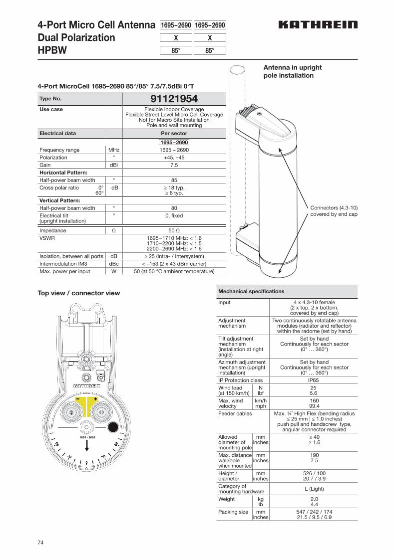
74
4-Port Micro Cell AntennaDual PolarizationHPBW
4-Port MicroCell 1695–2690 85°/85° 7.5/7.5dBi 0°T
Type No. 91121954Use case Flexible Indoor Coverage
Flexible Street Level Micro Cell CoverageNot for Macro Site Installation
Pole and wall mounting
Electrical data Per sector
1695–2690Frequency range MHz 1695 – 2690Polarization ° +45, –45Gain dBi 7.5Horizontal Pattern:Half-power beam width ° 85Cross polar ratio 0°
60°dB ≥ 18 typ.
≥ 8 typ.Vertical Pattern:Half-power beam width ° 80Electrical tilt(upright installation)
° 0, fixed
Impedance Ω 50 ΩVSWR 1695–1710 MHz: < 1.6
1710–2200 MHz: < 1.52200–2690 MHz: < 1.6
Isolation, between all ports dB ≥ 25 (Intra- / Intersystem)Intermodulation IM3 dBc < –153 (2 x 43 dBm carrier)Max. power per input W 50 (at 50 °C ambient temperature)
Mechanical specifications
Input 4 x 4.3-10 female(2 x top, 2 x bottom,covered by end cap)
Adjustment mechanism
Two continuously rotatable antenna modules (radiator and reflector) within the radome (set by hand)
Tilt adjustment mechanism (installation at right angle)
Set by handContinuously for each sector
(0° … 360°)
Azimuth adjustment mechanism (upright installation)
Set by handContinuously for each sector
(0° … 360°)IP Protection class IP65Wind load(at 150 km/h)
Nlbf
255.6
Max. wind velocity
km/hmph
16099.4
Feeder cables Max. ¼˝ High Flex (bending radius ≤ 25 mm | ≤ 1.0 inches)
push pull and handscrew type, angular connector required
Allowed dia meter of mounting pole
mminches
≥ 40≥ 1.6
Max. distance wall/pole when mounted
mminches
1907.5
Height / diameter
mminches
526 / 10020.7 / 3.9
Category ofmounting hardware L (Light)
Weight kglb
2.04.4
Packing size mminches
547 / 242 / 17421.5 / 9.5 / 6.9
1695–2690 1695–2690
X X
85° 85°
Antenna in upright pole installation
Connectors (4.3-10)covered by end cap
1695 - 2690
Top view / connector view
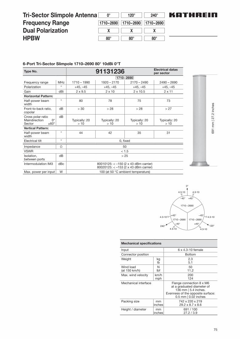
75
Tri-Sector Slimpole AntennaFrequency RangeDual PolarizationHPBW
1710–2690
0°
1710–2690
120°
1710–2690
240°
X
80°
X
80°
X
80°
Mechanical specifications
Input 6 x 4.3-10 femaleConnector position BottomWeight kg
lb2.35.1
Wind load (at 150 km/h)
Nlbf
5011.2
Max. wind velocity km/hmph
200124
Mechanical interface Flange connection 8 x M6at a graduated diameter of
136 mm | 5.4 inches.Evenness of the opposite surface:
0.5 mm | 0.02 inchesPacking size mm
inches742 x 220 x 21929.2 x 8.7 x 8.6
Height / diameter mminches
691 / 10027.2 / 3.9
6-Port Tri-Sector Slimpole 1710–2690 80° 10dBi 0°T
Type No. 91131236 Electrical datasper sector
1710–2690Frequency range MHz 1710 – 1990 1920 – 2170 2170 – 2490 2490 – 2690Polarization ° +45, –45 +45, –45 +45, –45 +45, –45Gain dBi 2 x 9.5 2 x 10 2 x 10.5 2 x 11Horizontal Pattern:Half-power beam width
° 80 78 75 73
Front-to-back ratio, copolar
dB > 30 > 28 > 28 > 27
Cross polar ratioMaindirection 0°Sector ±60°
dBTypically: 20
> 10Typically: 20
> 10Typically: 20
> 10Typically: 20
> 10Vertical Pattern:Half-power beam width
° 44 42 35 31
Electrical tilt ° 0, fixed
Impedance Ω 50VSWR < 1.5Isolation, between ports
dB > 25
Intermodulation IM3 dBc 80010125: < –150 (2 x 43 dBm carrier)80020125: < –153 (2 x 43 dBm carrier)
Max. power per input W 100 (at 50 °C ambient temperature)
4.3-10120°240°
0°
1710 –2690 1710 –2690
1710 –2690
4.3-10
4.3-104.3-10
4.3-10 4.3-10
+45°–45°
+45°
–45°+45°
–45°
691
mm
| 27
.2 in
ches
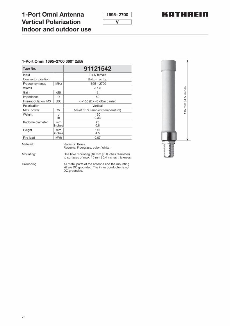
76
1-Port Omni AntennaVertical PolarizationIndoor and outdoor use
1695–2700
V
1-Port Omni 1695–2700 360° 2dBi
Type No. 91121542Input 1 x N femaleConnector position Bottom or topFrequency range MHz 1695 – 2700VSWR < 1.8Gain dBi 2Impedance Ω 50Intermodulation IM3 dBc < –150 (2 x 43 dBm carrier)Polarization VerticalMax. power W 50 (at 50 °C ambient temperature)Weight g
lb1500.33
Radome diameter mminches
200.8
Height mminches
1154.5
Fire load kWh 0.07
Material: Radiator: Brass.Radome: Fiberglass, color: White.
Mounting: One hole mounting (16 mm | 0.6 iches diameter) to surfaces of max. 10 mm | 0.4 inches thickness.
Grounding: All metal parts of the antenna and the mounting kit are DC grounded. The inner conductor is not DC grounded.
115
mm
| 4.
5 in
ches
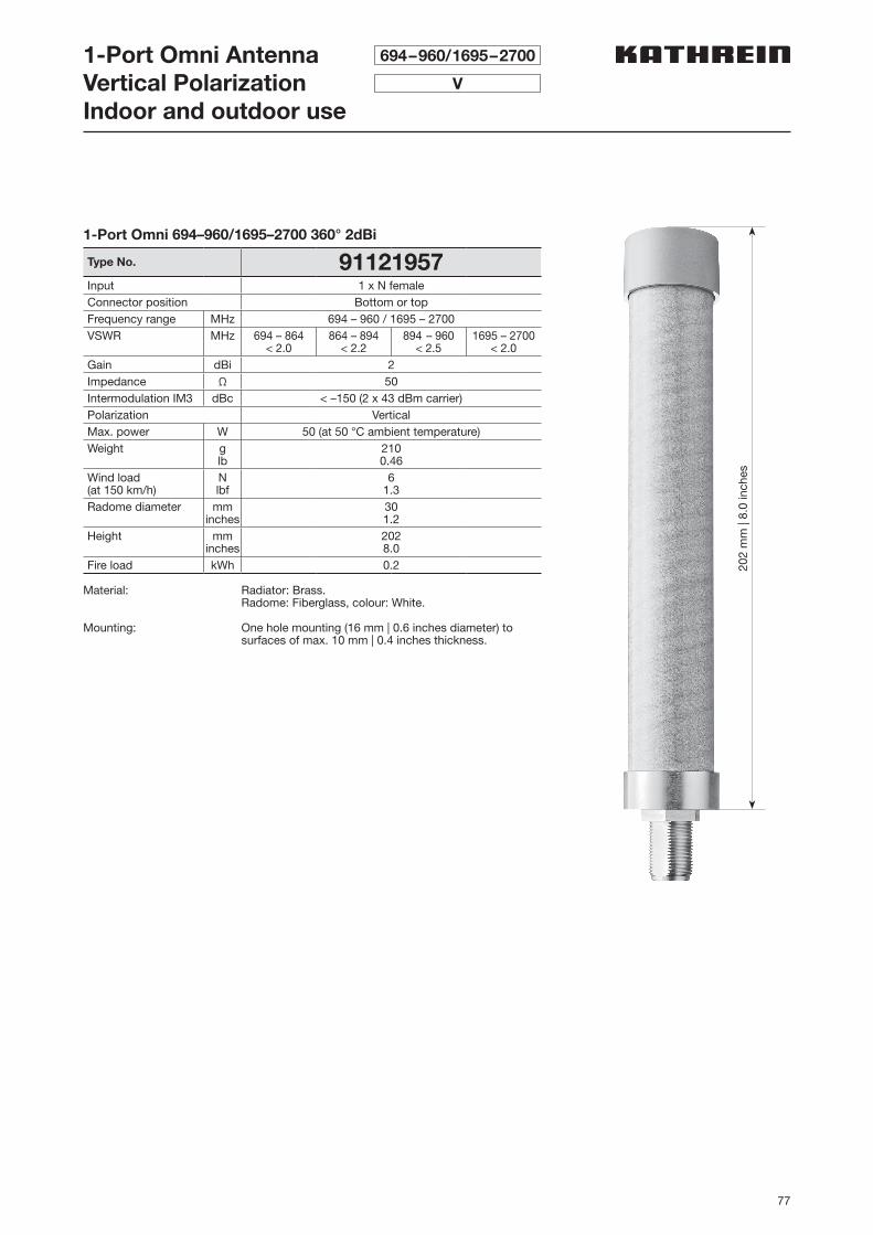
77
1-Port Omni AntennaVertical PolarizationIndoor and outdoor use
694–960/1695–2700
V
1-Port Omni 694–960/1695–2700 360° 2dBi
Type No. 91121957Input 1 x N femaleConnector position Bottom or topFrequency range MHz 694 – 960 / 1695 – 2700VSWR MHz 694 – 864
< 2.0864 – 894
< 2.2894 – 960
< 2.51695 – 2700
< 2.0Gain dBi 2Impedance Ω 50Intermodulation IM3 dBc < –150 (2 x 43 dBm carrier)Polarization VerticalMax. power W 50 (at 50 °C ambient temperature)Weight g
lb2100.46
Wind load(at 150 km/h)
Nlbf
61.3
Radome diameter mminches
301.2
Height mminches
2028.0
Fire load kWh 0.2
Material: Radiator: Brass.Radome: Fiberglass, colour: White.
Mounting: One hole mounting (16 mm | 0.6 inches diameter) to surfaces of max. 10 mm | 0.4 inches thickness.
202
mm
| 8.
0 in
ches
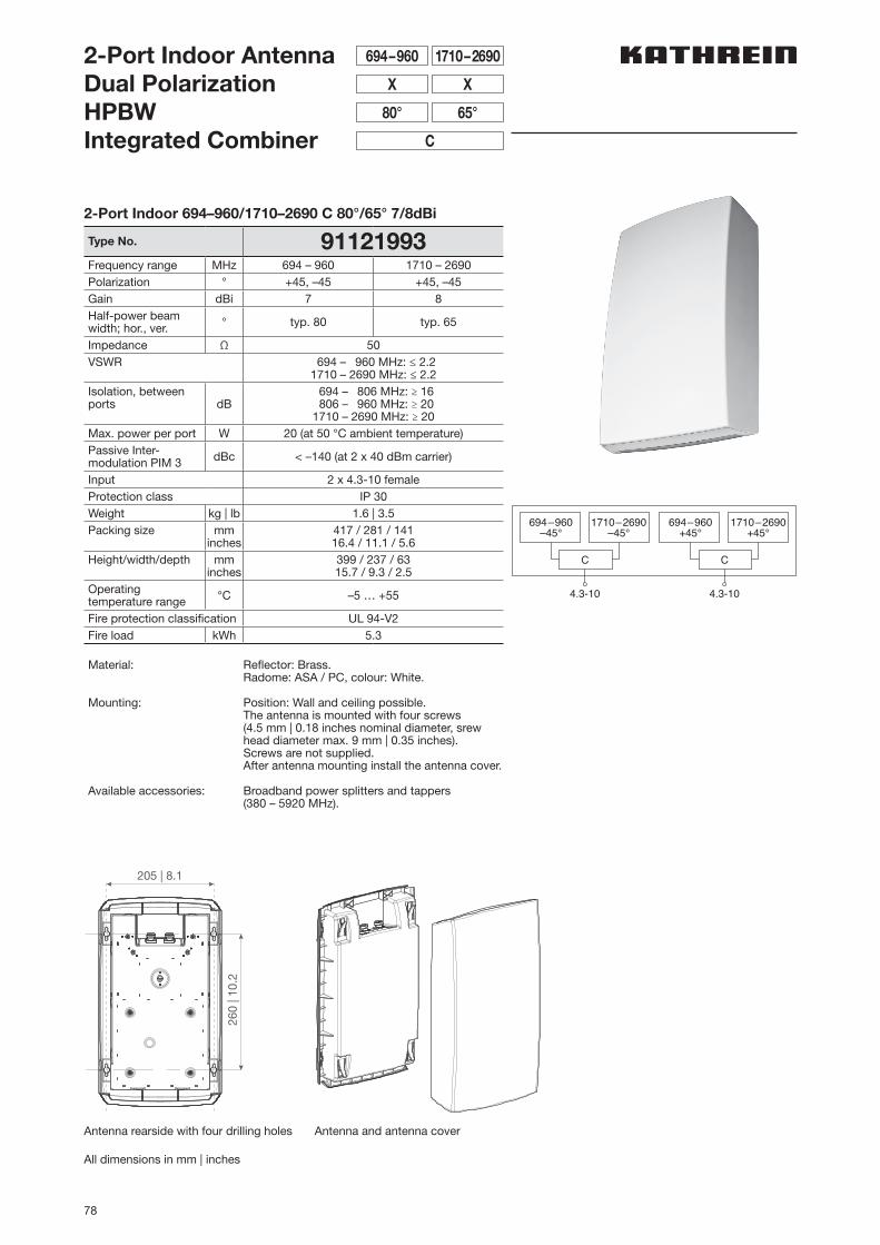
78
2-Port Indoor AntennaDual PolarizationHPBWIntegrated Combiner
1710–2690694–960
XX
65°80°
C
C
4.3-10
694–960–45°
1710–2690–45°
C
4.3-10
694–960+45°
1710–2690+45°
2-Port Indoor 694–960/1710–2690 C 80°/65° 7/8dBi
Type No. 91121993Frequency range MHz 694 – 960 1710 – 2690Polarization ° +45, –45 +45, –45Gain dBi 7 8Half-power beam width; hor., ver. ° typ. 80 typ. 65
Impedance Ω 50VSWR 694 – 960 MHz: ≤ 2.2
1710 – 2690 MHz: ≤ 2.2Isolation, between ports dB
694 – 806 MHz: ≥ 16 806 – 960 MHz: ≥ 201710 – 2690 MHz: ≥ 20
Max. power per port W 20 (at 50 °C ambient temperature)Passive Inter-modulation PIM 3 dBc < –140 (at 2 x 40 dBm carrier)
Input 2 x 4.3-10 femaleProtection class IP 30Weight kg | lb 1.6 | 3.5Packing size mm
inches417 / 281 / 14116.4 / 11.1 / 5.6
Height/width/depth mminches
399 / 237 / 6315.7 / 9.3 / 2.5
Operating temperature range °C –5 … +55
Fire protection classification UL 94-V2Fire load kWh 5.3
Material: Reflector: Brass.Radome: ASA / PC, colour: White.
Mounting: Position: Wall and ceiling possible.The antenna is mounted with four screws (4.5 mm | 0.18 inches nominal diameter, srew head dia meter max. 9 mm | 0.35 inches). Screws are not supplied. After antenna mounting install the antenna cover.
Available accessories: Broadband power splitters and tappers (380 – 5920 MHz).
Antenna rearside with four drilling holes
All dimensions in mm | inches
Antenna and antenna cover
260
| 10.
2
205 | 8.1
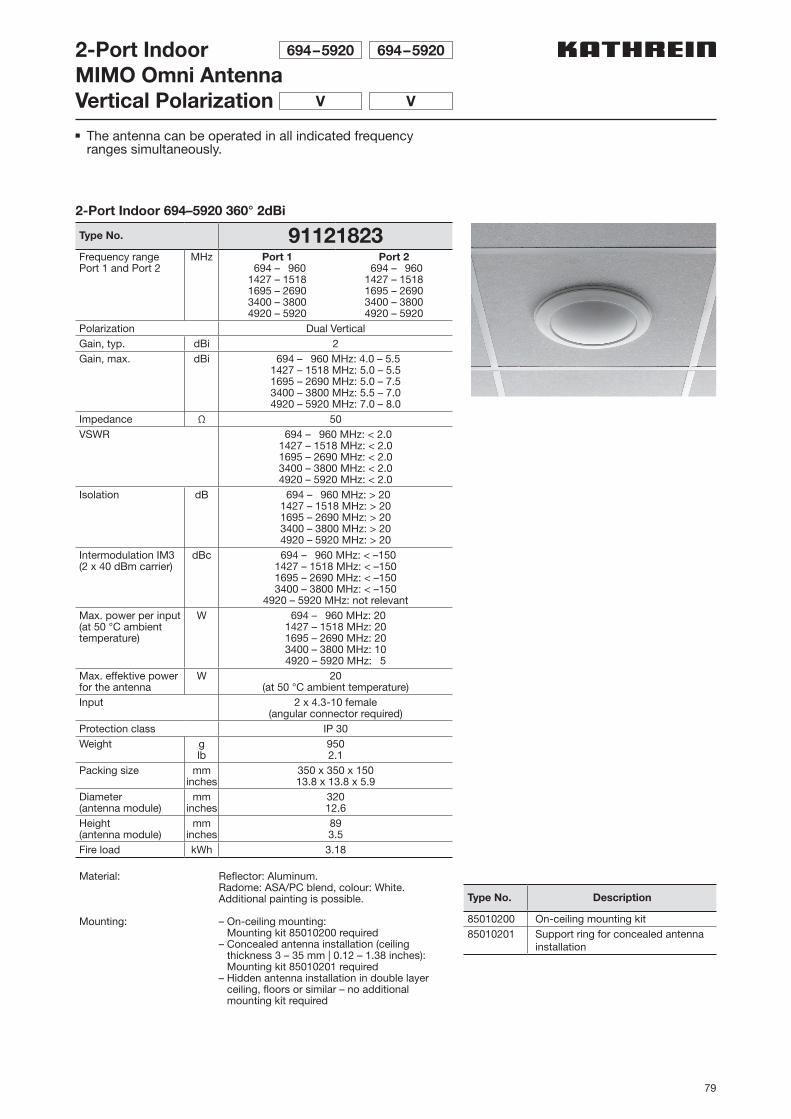
79
2-Port IndoorMIMO Omni AntennaVertical Polarization
694–5920 694–5920
V V
2-Port Indoor 694–5920 360° 2dBi
Type No. 91121823Frequency rangePort 1 and Port 2
MHz Port 1 694 – 9601427 – 15181695 – 26903400 – 38004920 – 5920
Port 2 694 – 9601427 – 15181695 – 26903400 – 38004920 – 5920
Polarization Dual VerticalGain, typ. dBi 2Gain, max. dBi 694 – 960 MHz: 4.0 – 5.5
1427 – 1518 MHz: 5.0 – 5.51695 – 2690 MHz: 5.0 – 7.53400 – 3800 MHz: 5.5 – 7.04920 – 5920 MHz: 7.0 – 8.0
Impedance Ω 50VSWR 694 – 960 MHz: < 2.0
1427 – 1518 MHz: < 2.01695 – 2690 MHz: < 2.03400 – 3800 MHz: < 2.04920 – 5920 MHz: < 2.0
Isolation dB 694 – 960 MHz: > 201427 – 1518 MHz: > 201695 – 2690 MHz: > 203400 – 3800 MHz: > 204920 – 5920 MHz: > 20
Intermodulation IM3(2 x 40 dBm carrier)
dBc 694 – 960 MHz: < –1501427 – 1518 MHz: < –1501695 – 2690 MHz: < –1503400 – 3800 MHz: < –150
4920 – 5920 MHz: not relevantMax. power per input(at 50 °C ambient temperature)
W 694 – 960 MHz: 201427 – 1518 MHz: 201695 – 2690 MHz: 203400 – 3800 MHz: 104920 – 5920 MHz: 5
Max. effektive power for the antenna
W 20(at 50 °C ambient temperature)
Input 2 x 4.3-10 female(angular connector required)
Protection class IP 30Weight g
lb9502.1
Packing size mminches
350 x 350 x 15013.8 x 13.8 x 5.9
Diameter (antenna module)
mminches
32012.6
Height (antenna module)
mminches
893.5
Fire load kWh 3.18
Material: Reflector: Aluminum.Radome: ASA/PC blend, colour: White. Additional painting is possible.
Mounting: – On-ceiling mounting: Mounting kit 85010200 required
– Concealed antenna installation (ceiling thickness 3 – 35 mm | 0.12 – 1.38 inches): Mounting kit 85010201 required
– Hidden antenna installation in double l ayer ceiling, floors or similar – no additional mounting kit required
Type No. Description
85010200 On-ceiling mounting kit85010201 Support ring for concealed antenna
installation
n The antenna can be operated in all indicated frequency ranges simultaneously.

80
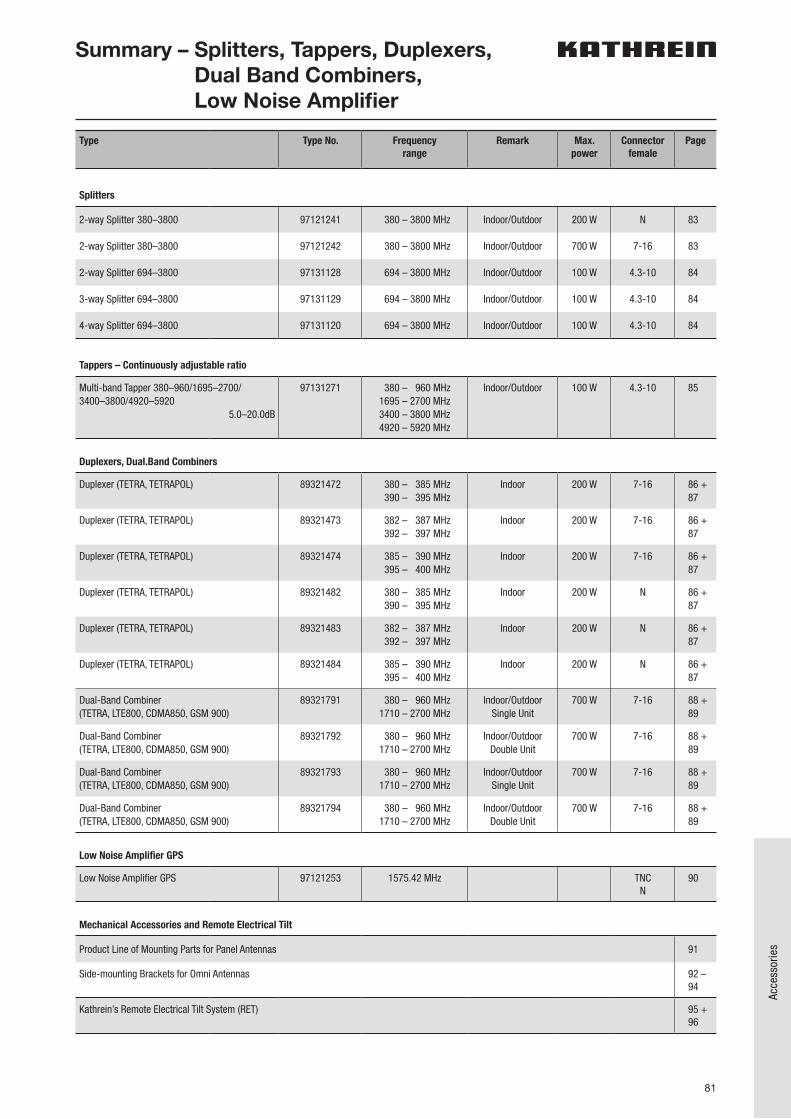
81
Acce
ssor
ies
Type Type No. Frequencyrange
Remark Max.power
Connector female
Page
Splitters
2-way Splitter 380–3800 97121241 380 – 3800 MHz Indoor/Outdoor 200 W N 83
2-way Splitter 380–3800 97121242 380 – 3800 MHz Indoor/Outdoor 700 W 7-16 83
2-way Splitter 694–3800 97131128 694 – 3800 MHz Indoor/Outdoor 100 W 4.3-10 84
3-way Splitter 694–3800 97131129 694 – 3800 MHz Indoor/Outdoor 100 W 4.3-10 84
4-way Splitter 694–3800 97131120 694 – 3800 MHz Indoor/Outdoor 100 W 4.3-10 84
Tappers – Continuously adjustable ratio
Multi-band Tapper 380–960/1695–2700/ 3400–3800/4920–5920
5.0–20.0dB
97131271 380 – 960 MHz1695 – 2700 MHz3400 – 3800 MHz4920 – 5920 MHz
Indoor/Outdoor 100 W 4.3-10 85
Duplexers, Dual.Band Combiners
Duplexer (TETRA, TETRAPOL) 89321472 380 – 385 MHz 390 – 395 MHz
Indoor 200 W 7-16 86 +87
Duplexer (TETRA, TETRAPOL) 89321473 382 – 387 MHz 392 – 397 MHz
Indoor 200 W 7-16 86 +87
Duplexer (TETRA, TETRAPOL) 89321474 385 – 390 MHz 395 – 400 MHz
Indoor 200 W 7-16 86 +87
Duplexer (TETRA, TETRAPOL) 89321482 380 – 385 MHz 390 – 395 MHz
Indoor 200 W N 86 +87
Duplexer (TETRA, TETRAPOL) 89321483 382 – 387 MHz 392 – 397 MHz
Indoor 200 W N 86 +87
Duplexer (TETRA, TETRAPOL) 89321484 385 – 390 MHz 395 – 400 MHz
Indoor 200 W N 86 +87
Dual-Band Combiner (TETRA, LTE800, CDMA850, GSM 900)
89321791 380 – 960 MHz1710 – 2700 MHz
Indoor/OutdoorSingle Unit
700 W 7-16 88 +89
Dual-Band Combiner (TETRA, LTE800, CDMA850, GSM 900)
89321792 380 – 960 MHz1710 – 2700 MHz
Indoor/OutdoorDouble Unit
700 W 7-16 88 +89
Dual-Band Combiner (TETRA, LTE800, CDMA850, GSM 900)
89321793 380 – 960 MHz1710 – 2700 MHz
Indoor/OutdoorSingle Unit
700 W 7-16 88 +89
Dual-Band Combiner (TETRA, LTE800, CDMA850, GSM 900)
89321794 380 – 960 MHz1710 – 2700 MHz
Indoor/OutdoorDouble Unit
700 W 7-16 88 +89
Low Noise Amplifier GPS
Low Noise Amplifier GPS 97121253 1575.42 MHz TNCN
90
Mechanical Accessories and Remote Electrical Tilt
Product Line of Mounting Parts for Panel Antennas 91
Side-mounting Brackets for Omni Antennas 92 – 94
Kathrein’s Remote Electrical Tilt System (RET) 95 + 96
Summary – Splitters, Tappers, Duplexers, Dual Band Combiners, Low Noise Amplifier

82
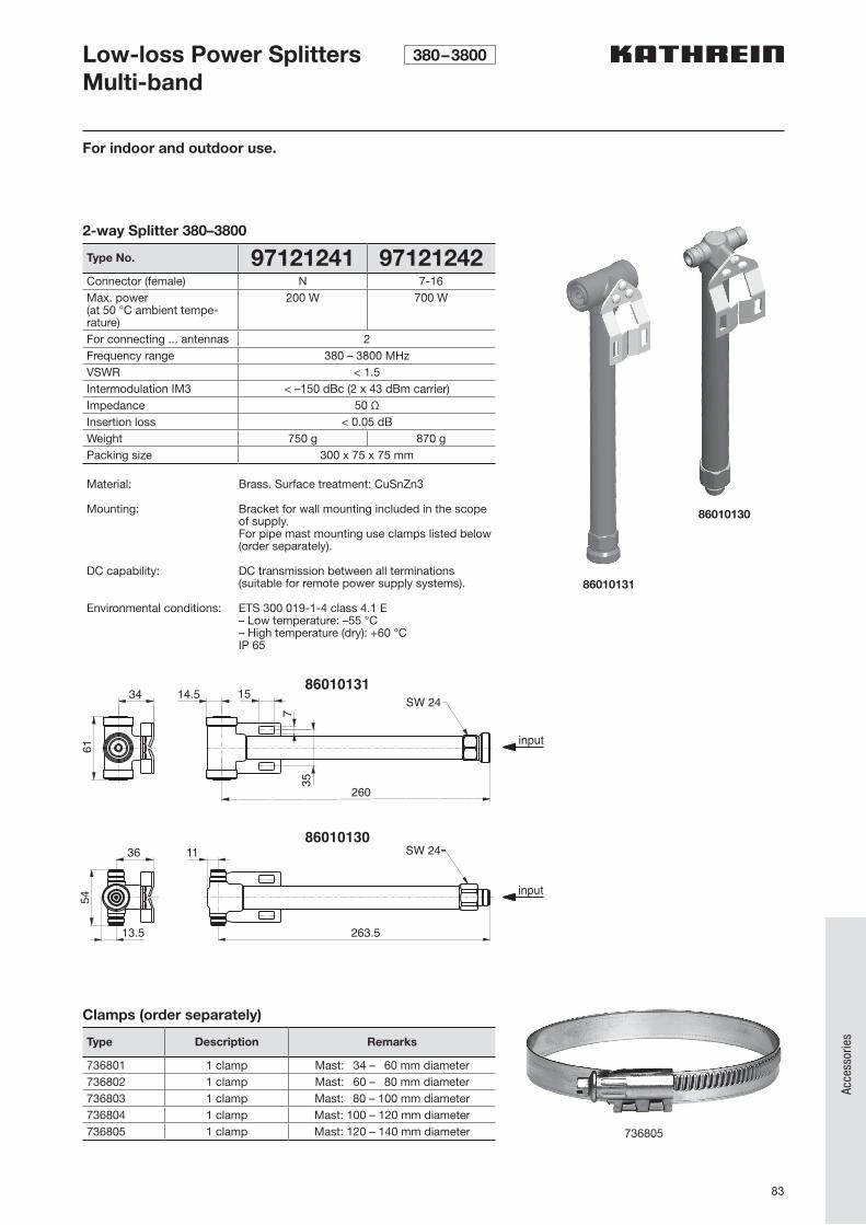
83
Acce
ssor
ies
2-way Splitter 380–3800
Type No. 97121241 97121242Connector (female) N 7-16Max. power(at 50 °C ambient tempe-rature)
200 W 700 W
For connecting ... antennas 2Frequency range 380 – 3800 MHzVSWR < 1.5Intermodulation IM3 < –150 dBc (2 x 43 dBm carrier)Impedance 50 ΩInsertion loss < 0.05 dBWeight 750 g 870 gPacking size 300 x 75 x 75 mm
Material: Brass. Surface treatment: CuSnZn3
Mounting: Bracket for wall mounting included in the scope of supply. For pipe mast mounting use clamps listed below (order separately).
DC capability: DC transmission between all terminations (suitable for remote power supply systems).
Environmental conditions: ETS 300 019-1-4 class 4.1 E– Low temperature: –55 °C– High temperature (dry): +60 °CIP 65
For indoor and outdoor use.
34 14.5 15
input
61
735
SW 2486010131
86010130
260
input
SW 24
263.5
36 11
54
13.5
86010131
86010130
736805
Clamps (order separately)
Type Description Remarks
736801 1 clamp Mast: 34 – 60 mm diameter736802 1 clamp Mast: 60 – 80 mm diameter736803 1 clamp Mast: 80 – 100 mm diameter736804 1 clamp Mast: 100 – 120 mm diameter736805 1 clamp Mast: 120 – 140 mm diameter
Low-loss Power SplittersMulti-band
380–3800
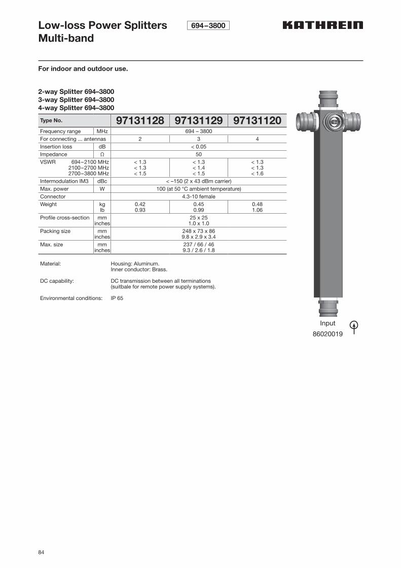
84
For indoor and outdoor use.
Low-loss Power SplittersMulti-band
694–3800
Input
86020019
2-way Splitter 694–38003-way Splitter 694–38004-way Splitter 694–3800
Type No. 97131128 97131129 97131120Frequency range MHz 694 – 3800For connecting ... antennas 2 3 4Insertion loss dB < 0.05Impedance Ω 50VSWR 694–2100 MHz
2100–2700 MHz2700–3800 MHz
< 1.3< 1.3< 1.5
< 1.3< 1.4< 1.5
< 1.3< 1.3< 1.6
Intermodulation IM3 dBc < –150 (2 x 43 dBm carrier)Max. power W 100 (at 50 °C ambient temperature)Connector 4.3-10 femaleWeight kg
lb0.420.93
0.450.99
0.481.06
Profile cross-section mminches
25 x 251.0 x 1.0
Packing size mminches
248 x 73 x 869.8 x 2.9 x 3.4
Max. size mminches
237 / 66 / 469.3 / 2.6 / 1.8
Material: Housing: Aluminum.Inner conductor: Brass.
DC capability: DC transmission between all terminations (suitbale for remote power supply systems).
Environmental conditions: IP 65
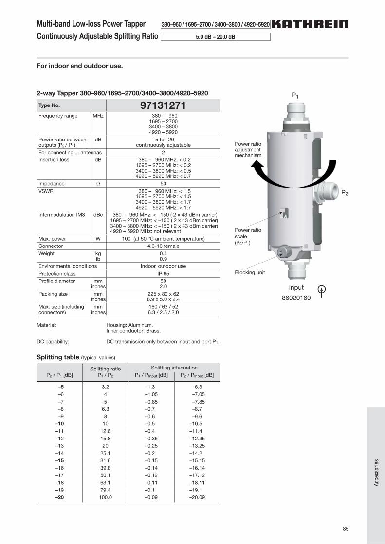
85
Acce
ssor
ies
Multi-band Low-loss Power TapperContinuously Adjustable Splitting Ratio
380–960 / 1695–2700 / 3400–3800 / 4920–5920
5.0 dB – 20.0 dB
2-way Tapper 380–960/1695–2700/3400–3800/4920–5920
Type No. 97131271Frequency range MHz 380 – 960
1695 – 27003400 – 38004920 – 5920
Power ratio between outputs (P2 / P1)
dB –5 to –20continuously adjustable
For connecting ... antennas 2Insertion loss dB 380 – 960 MHz: < 0.2
1695 – 2700 MHz: < 0.23400 – 3800 MHz: < 0.54920 – 5920 MHz: < 0.7
Impedance Ω 50VSWR 380 – 960 MHz: < 1.5
1695 – 2700 MHz: < 1.53400 – 3800 MHz: < 1.74920 – 5920 MHz: < 1.7
Intermodulation IM3 dBc 380 – 960 MHz: < –150 ( 2 x 43 dBm carrier)1695 – 2700 MHz: < –150 ( 2 x 43 dBm carrier)3400 – 3800 MHz: < –150 ( 2 x 43 dBm carrier)4920 – 5920 MHz: not relevant
Max. power W 100 (at 50 °C ambient temperature)Connector 4.3-10 femaleWeight kg
lb0.40.9
Environmental conditions Indoor, outdoor useProtection class IP 65Profile diameter mm
inches502.0
Packing size mminches
225 x 80 x 628.9 x 5.0 x 2.4
Max. size (including connectors)
mminches
160 / 63 / 526.3 / 2.5 / 2.0
Material: Housing: Aluminum.Inner conductor: Brass.
DC capability: DC transmission only between input and port P1.
For indoor and outdoor use.
Input
86020160
P2
P1
Blocking unit
Power ratio scale(P2/P1)
Power ratio adjustment mechanism
Splitting table (typical values)
P2 / P1 [dB]Splitting ratio
P1 / P2
Splitting attenuationP1 / PInput [dB] P2 / PInput [dB]
–5 3.2 –1.3 –6.3 –6 4 –1.05 –7.05 –7 5 –0.85 –7.85 –8 6.3 –0.7 –8.7 –9 8 –0.6 –9.6–10 10 –0.5 –10.5–11 12.6 –0.4 –11.4–12 15.8 –0.35 –12.35–13 20 –0.25 –13.25–14 25.1 –0.2 –14.2–15 31.6 –0.15 –15.15–16 39.8 –0.14 –16.14–17 50.1 –0.12 –17.12–18 63.1 –0.11 –18.11–19 79.4 –0.1 –19.1–20 100.0 –0.09 –20.09
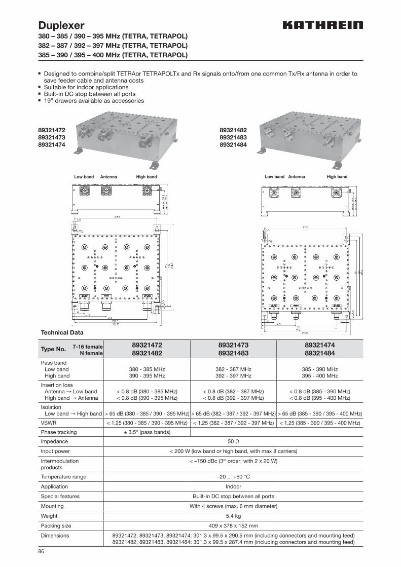
86
Duplexer380 – 385 / 390 – 395 MHz (TETRA, TETRAPOL) 382 – 387 / 392 – 397 MHz (TETRA, TETRAPOL)385 – 390 / 395 – 400 MHz (TETRA, TETRAPOL)
n Designed to combine/split TETRAor TETRAPOLTx and Rx signals onto/from one common Tx/Rx antenna in order to save feeder cable and antenna costs
n Suitable for indoor applicationsn Built-in DC stop between all portsn 19” drawers available as accessories
893214728932147389321474
893214828932148389321484
Low band Antenna High bandLow band Antenna High band
Technical Data
Type No.8932147289321482
8932147389321483
8932147489321484
Pass band Low band High band
380 - 385 MHz390 - 395 MHz
382 - 387 MHz392 - 397 MHz
385 - 390 MHz395 - 400 MHz
Insertion loss Antenna → Low band High band → Antenna
< 0.8 dB (380 - 385 MHz)< 0.8 dB (390 - 395 MHz)
< 0.8 dB (382 - 387 MHz)< 0.8 dB (392 - 397 MHz)
< 0.8 dB (385 - 390 MHz)< 0.8 dB (395 - 400 MHz)
Isolation Low band → High band > 65 dB (380 - 385 / 390 - 395 MHz) > 65 dB (382 - 387 / 392 - 397 MHz) > 65 dB (385 - 390 / 395 - 400 MHz)
VSWR < 1.25 (380 - 385 / 390 - 395 MHz) < 1.25 (382 - 387 / 392 - 397 MHz) < 1.25 (385 - 390 / 395 - 400 MHz)
Phase tracking ± 3.5° (pass bands)
Impedance 50 Ω
Input power < 200 W (low band or high band, with max 8 carriers)
Intermodulation products
< –150 dBc (3rd order; with 2 x 20 W)
Temperature range –20 ... +60 °C
Application Indoor
Special features Built-in DC stop between all ports
Mounting With 4 screws (max. 6 mm diameter)
Weight 5.4 kg
Packing size 409 x 378 x 152 mm
Dimensions 89321472, 89321473, 89321474: 301.3 x 99.5 x 290.5 mm (including connectors and mounting feed)89321482, 89321483, 89321484: 301.3 x 99.5 x 287.4 mm (including connectors and mounting feed)
7-16 femaleN female
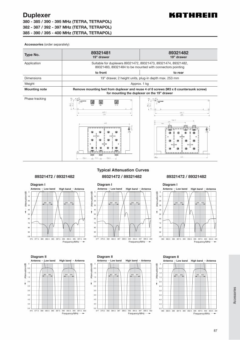
87
Acce
ssor
ies
Duplexer380 - 385 / 390 - 395 MHz (TETRA, TETRAPOL) 382 - 387 / 392 - 397 MHz (TETRA, TETRAPOL)385 - 390 / 395 - 400 MHz (TETRA, TETRAPOL)
Accessories (order separately)
Type No. 8932148119” drawer
8932148219” drawer
Application Suitable for duplexers 89321472, 89321473, 89321474, 89321482,89321483, 89321484 to be mounted with connectors pointing
to front to rear
Dimensions 19” drawer, 2 height units, plug-in depth max. 253 mm
Weight Approx. 1 kg
Mounting note Remove mounting feet from duplexer and reuse 4 of 8 screws (M3 x 8 countersunk screw)for mounting the duplexer on the 19” drawer
Phase tracking
Typical Attenuation Curves78210361 / 78210371
0
10
20
30
40
50
60
70
80
90
100
Atte
nuat
ion/
dB
Frequency/MHz375 377.5 380 382.5 385 387.5 390 392.5 395 397.5 400
380 – 385 390 – 395
Diagram IAntenna Low band High band Antenna
0
0.5
1.0
1.5
2.0
2.5
3.0
3.5
4.0
4.5
5.0
Atte
nuat
ion/
dB
Frequency/MHz375 377.5 380 382.5 385 387.5 390 392.5 395 397.5 400
390 – 395380 – 385
Diagram IIHigh band AntennaAntenna Low band
0
10
20
30
40
50
60
70
80
90
100
Atte
nuat
ion/
dB
Frequency/MHz377 379.5 382 384.5 387 389.5 392 394.5 397 399.5 402
382 – 387 392 – 397
Diagram IAntenna Low band High band Antenna
0
0.5
1.0
1.5
2.0
2.5
3.0
3.5
4.0
4.5
5.0
Atte
nuat
ion/
dB
Frequency/MHz377 379.5 382 384.5 387 389.5 392 394.5 397 399.5 402
392 – 397382 – 387
Diagram IIHigh band AntennaAntenna Low band
0
10
20
30
40
50
60
70
80
90
100
Atte
nuat
ion/
dB
Frequency/MHz380 382.5 385 387.5 390 392.5 395 397.5 400 402.5 405
385 – 390 395 – 400
Diagram IAntenna Low band High band Antenna
0
0.5
1.0
1.5
2.0
2.5
3.0
3.5
4.0
4.5
5.0
Atte
nuat
ion/
dB
Frequency/MHz380 382.5 385 387.5 390 392.5 395 397.5 400 402.5 405
395 – 400385 – 390
Diagram IIHigh band AntennaAntenna Low band
78210362 / 78210372 78210363 / 7821037389321472 / 89321482 89321472 / 89321482 89321472 / 89321482
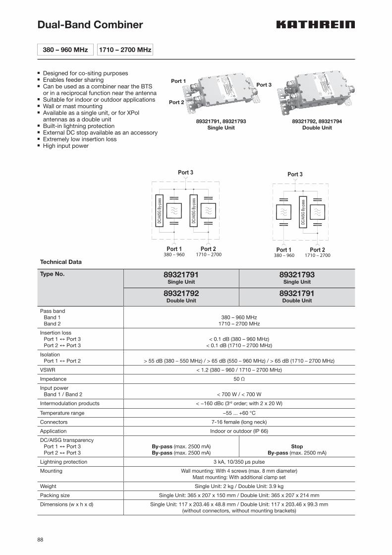
88
n Designed for co-siting purposesn Enables feeder sharingn Can be used as a combiner near the BTS
or in a reciprocal function near the antennan Suitable for indoor or outdoor applicationsn Wall or mast mountingn Available as a single unit, or for XPol
antennas as a double unitn Built-in lightning protectionn External DC stop available as an accessoryn Extremely low insertion lossn High input power
Technical Data
Type No. 89321791Single Unit
89321793Single Unit
89321792Double Unit
89321791Double Unit
Pass band Band 1 Band 2
380 – 960 MHz 1710 – 2700 MHz
Insertion loss Port 1 ↔ Port 3 Port 2 ↔ Port 3
< 0.1 dB (380 – 960 MHz)< 0.1 dB (1710 – 2700 MHz)
Isolation Port 1 ↔ Port 2 > 55 dB (380 – 550 MHz) / > 65 dB (550 – 960 MHz) / > 65 dB (1710 – 2700 MHz)
VSWR < 1.2 (380 – 960 / 1710 – 2700 MHz)
Impedance 50 Ω
Input power Band 1 / Band 2
< 700 W / < 700 W
Intermodulation products < −160 dBc (3rd order; with 2 x 20 W)
Temperature range −55 ... +60 °C
Connectors 7-16 female (long neck)
Application Indoor or outdoor (IP 66)
DC/AISG transparency Port 1 ↔ Port 3 Port 2 ↔ Port 3
By-pass (max. 2500 mA)By-pass (max. 2500 mA)
StopBy-pass (max. 2500 mA)
Lightning protection 3 kA, 10/350 µs pulse
Mounting Wall mounting: With 4 screws (max. 8 mm diameter)Mast mounting: With additional clamp set
Weight Single Unit: 2 kg / Double Unit: 3.9 kg
Packing size Single Unit: 365 x 207 x 150 mm / Double Unit: 365 x 207 x 214 mm
Dimensions (w x h x d) Single Unit: 117 x 203.46 x 48.8 mm / Double Unit: 117 x 203.46 x 99.3 mm (without connectors, without mounting brackets)
Dual-Band Combiner
380 – 960 MHz 1710 – 2700 MHz
380 – 960 1710 – 2700 380 – 960 1710 – 2700
Port 1Port 3
Port 2
89321791, 89321793 Single Unit
89321792, 89321794 Double Unit
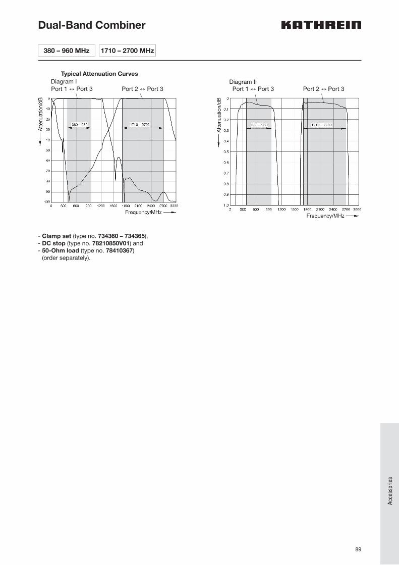
89
Acce
ssor
ies
Dual-Band Combiner
Typical Attenuation Curves Diagram IPort 1 ↔ Port 3 Port 2 ↔ Port 3
Diagram II
- Clamp set (type no. 734360 – 734365),- DC stop (type no. 78210850V01) and- 50-Ohm load (type no. 78410367)
(order separately).
Port 1 ↔ Port 3 Port 2 ↔ Port 3
380 – 960 MHz 1710 – 2700 MHz
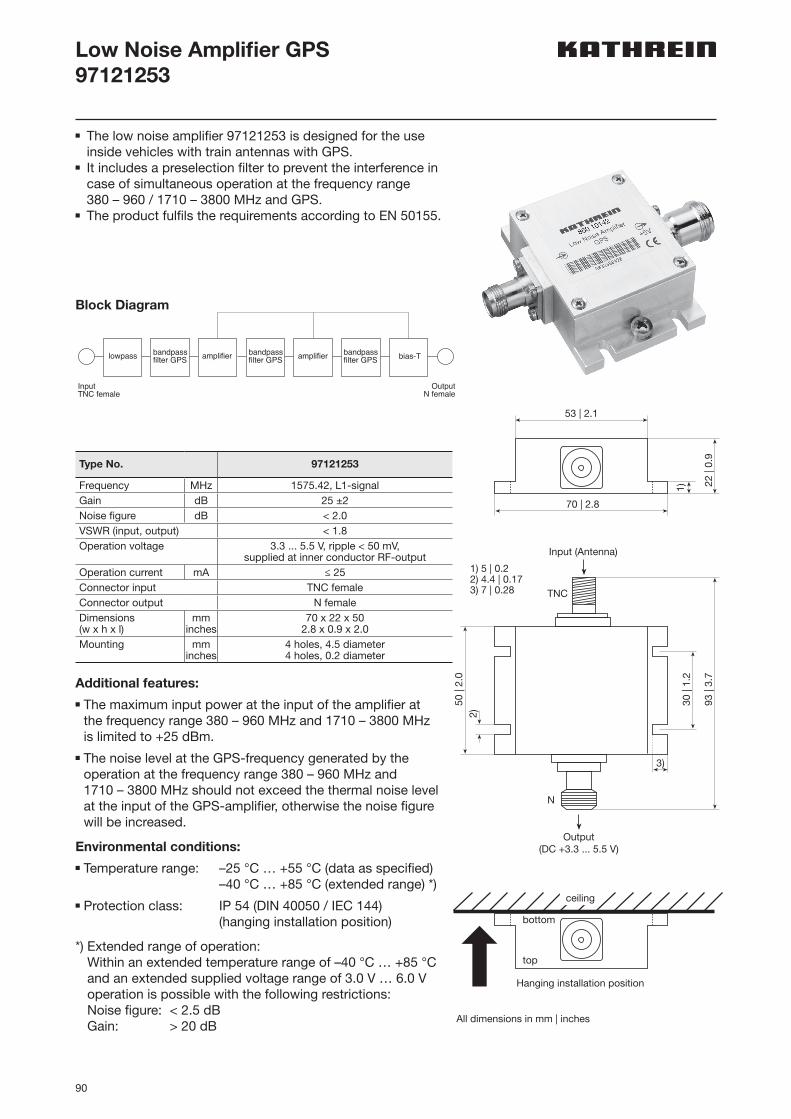
90
Low Noise Amplifier GPS97121253
n The low noise amplifier 97121253 is designed for the use inside vehicles with train antennas with GPS.
n It includes a preselection filter to prevent the inter ference in case of simultaneous operation at the frequency range 380 – 960 / 1710 – 3800 MHz and GPS.
n The product fulfils the requirements according to EN 50155.
Block Diagram
InputTNC female
OutputN female
bias-Tbandpassfilter GPS
bandpassfilter GPS
bandpassfilter GPSamplifier amplifierlowpass
Type No. 97121253
Frequency MHz 1575.42, L1-signalGain dB 25 ±2Noise figure dB < 2.0VSWR (input, output) < 1.8Operation voltage 3.3 ... 5.5 V, ripple < 50 mV,
supplied at inner conductor RF-outputOperation current mA ≤ 25Connector input TNC femaleConnector output N femaleDimensions (w x h x l)
mminches
70 x 22 x 502.8 x 0.9 x 2.0
Mounting mminches
4 holes, 4.5 diameter4 holes, 0.2 diameter
Additional features:n The maximum input power at the input of the amplifier at
the frequency range 380 – 960 MHz and 1710 – 3800 MHz is limited to +25 dBm.
n The noise level at the GPS-frequency generated by the operation at the frequency range 380 – 960 MHz and 1710 – 3800 MHz should not exceed the thermal noise level at the input of the GPS-amplifier, otherwise the noise figure will be increased.
Environmental conditions:n Temperature range: –25 °C … +55 °C (data as specified)
–40 °C … +85 °C (extended range) *)n Protection class: IP 54 (DIN 40050 / IEC 144)
(hanging installation position)
*) Extended range of operation: Within an extended temperature range of –40 °C … +85 °C and an extended supplied voltage range of 3.0 V … 6.0 V operation is possible with the following restrictions: Noise figure: < 2.5 dB Gain: > 20 dB
53 | 2.1
70 | 2.8
22 |
0.9
1)
2)50
| 2.
0
3)
30 |
1.2
Input (Antenna)
TNC
93 |
3.7
Output(DC +3.3 ... 5.5 V)
N
Hanging installation position
bottom
top
ceiling
1) 5 | 0.22) 4.4 | 0.173) 7 | 0.28
All dimensions in mm | inches
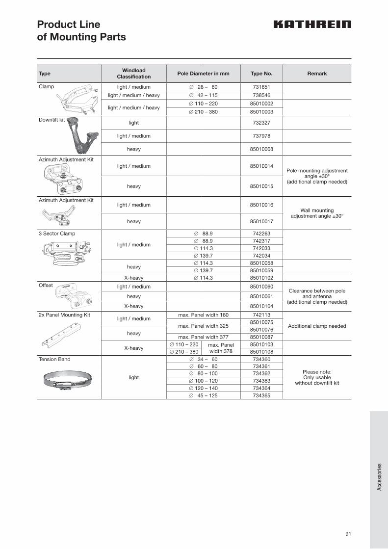
91
Acce
ssor
ies
TypeWindload
ClassificationPole Diameter in mm Type No. Remark
Clamp light / medium ∅ 28 – 60 731651
light / medium / heavy ∅ 42 – 115 738546
light / medium / heavy∅ 110 – 220 85010002
∅ 210 – 380 85010003
Downtilt kit light 732327
light / medium 737978
heavy 85010008
Azimuth Adjustment Kitlight / medium 85010014
Pole mounting adjustment angle ±30°
(additional clamp needed)heavy 85010015
Azimuth Adjustment Kitlight / medium 85010016
Wall mounting adjustment angle ±30°
heavy 85010017
3 Sector Clamp
light / medium
∅ 88.9 742263∅ 88.9 742317∅ 114.3 742033∅ 139.7 742034
heavy∅ 114.3 85010058∅ 139.7 85010059
X-heavy ∅ 114.3 85010102Offset light / medium 85010060
Clearance between pole and antenna
(additional clamp needed)heavy 85010061
X-heavy 85010104
2x Panel Mounting Kitlight / medium
max. Panel width 160 742113
Additional clamp neededmax. Panel width 32585010075
heavy85010076
max. Panel width 377 85010087
X-heavy∅ 110 – 220 max. Panel
width 37885010103
∅ 210 – 380 85010108Tension Band
light
∅ 34 – 60 734360
Please note: Only usable
without downtilt kit
∅ 60 – 80 734361∅ 80 – 100 734362∅ 100 – 120 734363∅ 120 – 140 734364∅ 45 – 125 734365
Product Lineof Mounting Parts
GF
Mounting support clamp
3 sector clamp
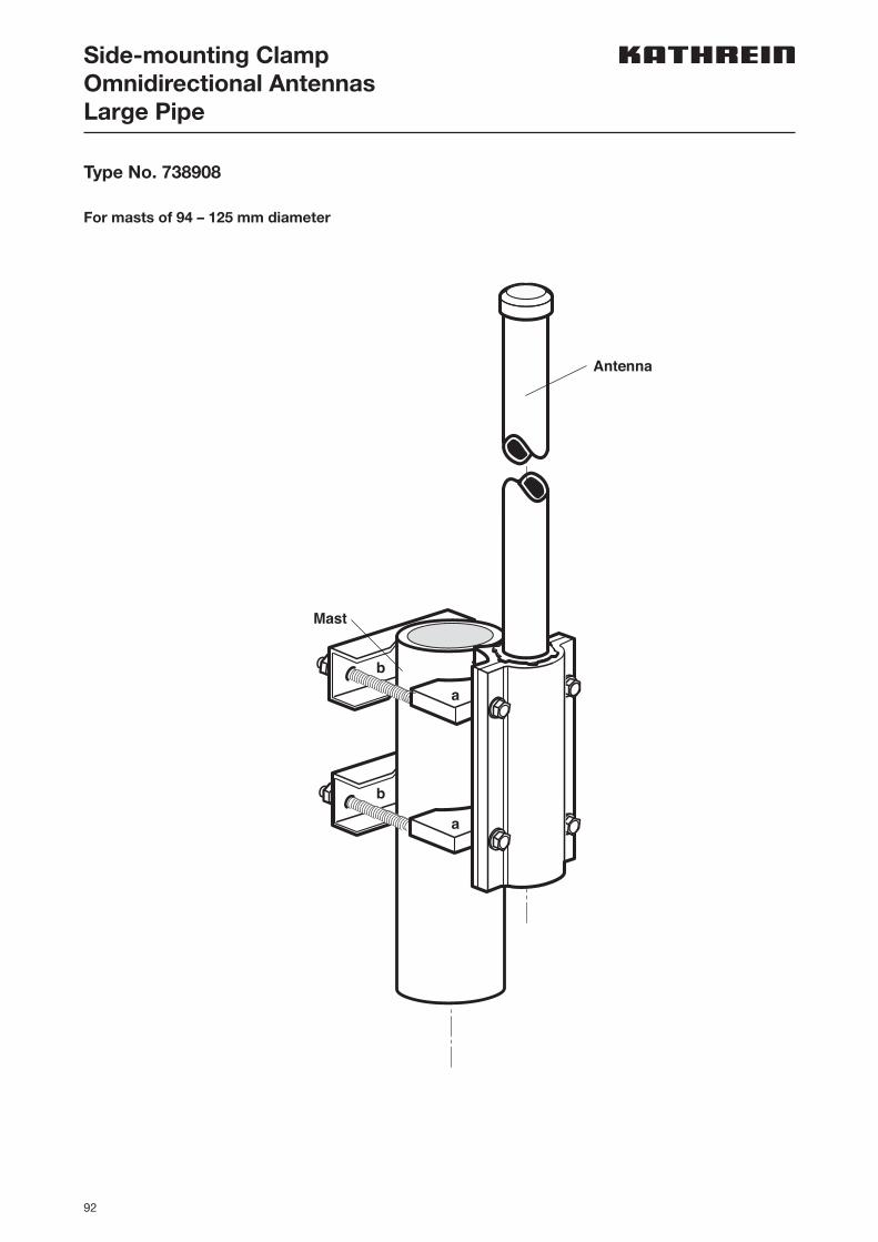
92
Type No. 738908
For masts of 94 – 125 mm diameter
Antenna
Mast
a
b
b
a
Side-mounting ClampOmnidirectional AntennasLarge Pipe
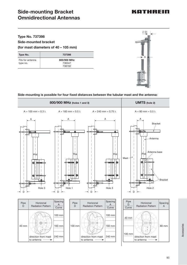
93
Acce
ssor
ies
Side-mounting BracketOmnidirectional Antennas
800/900 MHz (holes 1 and 3) UMTS (hole 2)
Side-mounting is possible for four fixed distances between the tubular mast and the antenna:
A
∅ D
AA
Bracket
Antenna
Bracket
Mast
Antenna base
A A
D D D DHole 2 Hole 3Hole 1Hole 3
AA
Bracket
Antenna
Bracket
Mast
Antenna base
A A
D D D DHole 2 Hole 3Hole 1Hole 3
AA
Bracket
Antenna
Bracket
Mast
Antenna base
A A
D D D DHole 2 Hole 3Hole 1Hole 3
AA
Bracket
Antenna
Bracket
Mast
Antenna base
A A
D D D DHole 2 Hole 3Hole 1Hole 3
A = 100 mm = 0.3 λ A = 160 mm = 0.5 λ A = 240 mm = 0.75 λ A = 80 mm = 0.5 λ
Pipe D
HorizonalRadiation Pattern
SpacingA
Curve
40 mm
direction from mastto antenna
100 mm
160 mm
240 mm
3
0
dB
Pipe D
HorizonalRadiation Pattern
SpacingA
Curve
100 mm
direction from mastto antenna
100 mm
160 mm
240 mm
3
0
dB
Pipe D
Curve
HorizonalRadiation Pattern
SpacingA
40 mm
direction from mastto antenna
80 mm
100 mm
3
0
dB
Type No. 737398
Side-mounted bracket
(for mast diameters of 40 – 105 mm)
Type No. 737398
Fits for antennatype no.
800/900 MHz736347738192
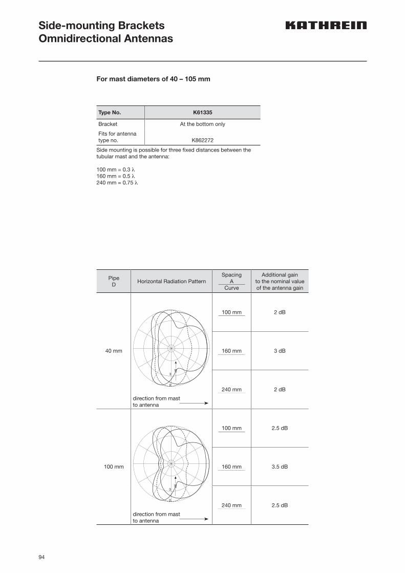
94
Side-mounting BracketsOmnidirectional Antennas
Type No. K61335
Bracket At the bottom only
Fits for antennatype no. K862272
Side mounting is possible for three fixed distances between the tubular mast and the antenna:
100 mm = 0.3 λ160 mm = 0.5 λ240 mm = 0.75 λ
PipeD
Horizontal Radiation PatternSpacing
ACurve
Additional gain to the nominal value of the antenna gain
40 mm
direction from mastto antenna
100 mm 2 dB
160 mm 3 dB
240 mm 2 dB
100 mm
direction from mastto antenna
100 mm 2.5 dB
160 mm 3.5 dB
240 mm 2.5 dB
3
0
dB
3
0
dB
For mast diameters of 40 – 105 mm
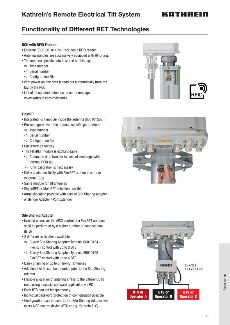
95
Acce
ssor
ies
RCU with RFID Featuren External RCU 86010148V01 includes a RFID readern Antenna spindles are successively equipped with RFID tagsn The antenna specific data is stored on this tag: a Type number a Serial number a Configuration File
n With power on, the data is read out automatically from the tag by the RCU
n List of all updated antennas on our homepage: www.kathrein.com/rfidspindle
FlexRETn Integrated RET module inside the antenna (86010153V01)n Pre-configured with the antenna specific parameters: a Type number a Serial number a Configuration file
n Calibrated ex-factoryn The FlexRET module is exchangeable a Automatic data transfer in case of exchange with
internal RFID taga Only calibration is neccessary
n Daisy chain possibility with FlexRET antennas and / or external RCUs
n Same module for all antennasn SingleRET or MultiRET selection possiblen Array allocation possible with special Site Sharing Adapter
or Gender Adapter / Port Extender
Site Sharing Adaptern Needed whenever the AISG control of a FlexRET antenna
shall be performed by a higher number of base stations (BTS)
n 2 different realizations available a 3-way Site Sharing Adapter: Type no. 86010154 –
FlexRET control with up to 3 BTS a 6-way Site Sharing Adapter: Type no. 86010155 –
FlexRET control with up to 6 BTSn Daisy chaining of up to 3 FlexRET antennasn Additional ALDs can be mounted prior to the Site Sharing
Adaptern Flexible allocation of antenna arrays to the different BTS
units using a special software application via PCn Each BTS can act independentlyn Individual password protection of configuration possiblen Configuration can be sent to the Site Sharing Adapter with
every AISG control device (BTS or e.g. Kathrein ALC)
Kathrein’s Remote Electrical Tilt System
Functionality of Different RET Technologies
BTS or Operator A
BTS or Operator B
BTS or Operator C
3 x AISG in1 x FlexRET out
86010154

96
Kathrein’s Remote Electrical Tilt System
Functionality of Different RET Technologies
Manuals for all our AISG control devices and for the Site Sharing Adapter as well as the corresponding software downloads can be found on our homepage in the section “Technical Documents” respectively “Driver and Software”.
For details of the RET system please also see Kathrein’s RET brochure.
Kathrein’s overall RET system works in accordance with the AISG (Antenna Interface Standards Group) standard and 3GPP (3rd Generation Part ner ship Project).
MOBILECOMMUNICATION
Remote Electrical Tilt SystemOverview of Products, Installation, Control Possibilities and FAQs
Gender Adapter (86010162)n Can be used if 2 base stations (BTS) are interconnected to
one common FlexRET antennan Mounted on the FlexRET output of the modulen Converts the AISG output to an AISG inputn The allocation of the antenna arrays can easily be
performed during the commissioning process via the BTS
Port Extender (86010163)n Can be used if 2 BTS are interconnected to common
FlexRET antennas in daisy chainn Mounted on the FlexRET module by 2 screwsn Converts 1 FlexRET input and output to 2 FlexRET inputs
and outputsn Daisy chaining with further FlexRET antennas and / or
external RCUsn The allocation of the antenna arrays can easily be
performed during the commissioning process via the BTS

9981
2794
/0/0
517/
PSA/
pdf |
Tec
hnic
al d
ata
subj
ect t
o ch
ange
.
Titl
e: iS
tock
.com
| Bl
ue_C
utle
r, GB
Perk
ins,
traf
fic_a
nalyz
er; F
otol
ia.c
om |
Tyle
r Ols
on
KATHREIN Special Communications GmbHProf.-Dr.-Anton-Kathrein-Str. 16342 Niederndorf bei Kufstein, AustriaPhone +49 8031 184-9351www.kathrein.com | [email protected]