9641612 - kle 150gt instruction manual and part manual · electrical water line drain line - 120v...
TRANSCRIPT

Headquarters: 20531 Crescent Bay Drive, Lake Forest, CA 92630 U.S.A. (949) 595-4800 Toronto, Ontario, Canada: 2283 Argentia Road, Unit 3, Mississauga, Ontario, Canada L5N 5Z2 (905) 542-2333 London England: Unit 15 Brunel Centre, Newton Road, Crawley, West Sussex, U.K. RH102UB (44) 1293-615570 Sydney, Australia: Unit 28, 317-321 Woodpark Road, Smithfield N.S.W., 2164 Australia (61)29.725.2588 Netherlands: 68 Marssteden, 7547 TD Enschede Holland 31.53.4285800
./(����*7��
INSTRUCTION AND
PART MANUAL
CONTENTS INSTRUCTION MANUAL INTRODUCTION Page 1 INSTALLATION Page 1 INITIAL OPERATION Page 2 TIME SETTINGS Page 3 JUMPER SETTINGS Page 4 CIRCUIT BOARD BUTTONS Page 4 NORMAL OPERATION Page 4 PROOF OF FLOW Page 5 PROOF OF FLOW Page 6 MAINTENANCE SCHEDULE Page 7 TROUBLESHOOTING Page 8 ELECTRICAL DIAGRAM Page 9 WARRANTY Page 10
PARTS MANUAL Page 11 ELECTRICAL BOX Page 12 DOOR Page 13 CABINET Page 14 SPRAY ARM Page 15 PLUMBING Page 16 DRAIN Page 17
'LVKPDFKLQH
(8/01) Revision A EO 3986 Part No. 9641612

Electrical Water line Drain line
- 120V 20 AMP circuit or - 240V 10 AMP circuit (not field convertible) connection box on the tray stand.
20 psi flow pressure 140 deg. F 3/4” FPT lower left side 4 inches above floor.
1-1/2” MPT on scrap accumulator Lower right side, 6 inches above floor.
4. Place the dishwasher at the spot desired for normal operation. Level the dishwasher using adjustable bullet feet at the bottom of the legs. Install spray arm included in the accessory box.
5. Connect hot water supply line to the 3/4 FPT elbow at bottom-left of machine. In-sure that water pressure is sufficient for fill (approx. 10 GPM flow @ 20 psi.). Connect drain to 1-1/2” MPT nipple on scrap accu-mulator to the lower right.
6. Make electrical connections (refer to data plate for voltage and current ratings) to the stationary conduit box located on the stand tray behind electrical box. Remove cover from stationary conduit box and make connections (use appropriate wire size) . Run all electrical wire through suit-able conduit and insure all connections are made in accordance with local wiring codes. It is recommended that the circuit breaker carrying the dishwasher load have NO OTHER ELECTRICAL DEVICES and dishwasher is directly connected to the circuit breaker.
INTRODUCTION The KLE 150 GT dishwasher is designed to provide years of excellent warewash results under many types of conditions. This unit is configured as a push button start dishwasher. The dishwasher includes a three product chemical dispenser which dispenses liquid detergent, rinse product, and a chemical sanitizer suitable for low temperature (recommended 140 deg. F applications.) Options and additional features are also available. Contact your nearest Knight representative for more details. INSTALLATION - Caution – Access into electrical enclosure must be performed by authorized personnel. 1. Inspect the dishwasher upon initial receipt. Open the door and locate the accessory package inside the dishwasher. Note that it includes a spray arm and other equipment required for installation. 2. Examine the spot where the dishwasher is to be operated. Insure that all electrical and plumbing connec-tions have been considered for installation Parameters:
Page No. 1
3/4 FPT
1-1/2 MPT
3. Install detergent, sanitizer, and rinse tubing to the inlet side of the peristaltic pumps. Use the provided hose clamp ties to secure tubing to squeeze tubing. If machine is ordered with Chem. alarm option, see page 6 for instructions.
(8/01) Revision A EO3986 Part No. 9641612
Name plate
READ ALL INSTRUCTION BEFORE INSTALLATION

Water level
INITIAL OPERATION 1. Check pump intake screen for proper installation. 2. Start with all switches in the OFF position.
3. Turn on main power switch. Open and close door to reset the control board. With door closed, flip up the fill button to fill the dishwasher with fresh 140 deg. F water (120 deg. F min). Fill until level with top of drain ball stem (over flow point).
4. Press the RUN POWER switch and with door in closed position the machine will start to wash. Allow ma-chine to run through one cycle and watch machine sequence through the following wash cycle: (90 second cy-cle evaluated). 120 second cycle consists of 50 second wash, 15 second drain and 55 second rinse. See pages 3,4 and 9 for more details on 72, and 120 cycles.
1 second – wash pump motor turns on
3 seconds – detergent pump runs for adjusted period of time.
45 seconds – drain opens and machine drains for 15 seconds.
Adjustable 48 to 60 seconds – fresh water valve opens and rinses inside of dishwasher (drain is still open)
60 seconds – drain closes and fill remains open for period of time to fill dish machine.
70 seconds – sanitizer and rinse pumps run for an adjustable period of time.
70 seconds – wash pump motor stops for three seconds then starts to “burp” the machine.
90 seconds – machine will stop. This is the end of the wash cycle.
5. Machine is factory adjusted but may need to be adjusted to your location water pressure to operate properly.
TIME 0
10
20
30
40
50
60
70
80
90
Page No. 2
Hook tab under rod
(8/01) Revision A EO 3986 Part No. 9641612

TIME SETTINGS Time settings will need to be done by authorized personnel only. The time settings for detergent pump, fresh water fill, sanitizer pump, and rinse pump are done inside the control box using the single turn pots. The pots control the time duration of each of the listed components. Use the chart below to make settings.
POT
CONTROL
ACTIVE TIME IN 90 SECONDS
SPAN OF POT
TIME ADJUSTMENT
COMMENTS
Detergent Pump
at time = 3 seconds
2-30 seconds
pot turns from 7 o'clock to 5 o'clock or 10 division. Each division is 2.7 seconds. Pump flow is approxi-mately 1.3 ml/sec.
Sani Pump
at time = 70 seconds
0-15 seconds
pot turns 7 o'clock to 5 o'clock or 10 divisions. Each division is 1.5 seconds. Pump flow is approximately 1.3 ml/sec.
Rinse Pump
at time = 70 seconds
0-15 seconds
pot turns 7 o'clock to 5 o'clock or 10 divisions. Each division is 1.5 seconds. Pump flow is approximately 1.3 ml/sec.
Fill Start
at time = 48 to 59
seconds
0-11 seconds
fill start is activated during the fixed drain cycle (45 to 60 seconds) at the 7 o'clock setting time is 0 and will start fill at 48 seconds in cycle. At the 5 o'clock setting time is 11 seconds and will start fill at 59 seconds in cycle. Fill start is set according to water pressure and the required time to rinse debris down the drain. Normal setting at 20 psi flow pressure is 12 o'clock or 5.5 seconds.
Fill Time
determined by fill start
10-42 seconds
begins at the setting of the fill start. Once fill start is set the fill time determines the duration of time fresh water solenoid valve remains open. 7 o'clock setting time is 10 seconds, 5 o'clock setting time is 42 sec-onds. Adjust according to water pressure. Normal setting at 20 psi flow pressure is 11 o'clock
or 15 seconds.
Pump motor relay sanitizer pump pot rinse pump pot Fill time pot Fill start pot
Page No. 3 (8/01) Revision A EO3986 Part No. 9641612
FUSE 2A, 250V FUSE 2A, 250 V FUSE 1A, 250V FUSE 1 A, 250 V
Det. Pump pot
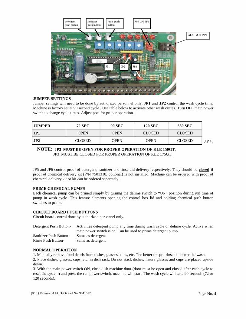
JUMPER SETTINGS Jumper settings will need to be done by authorized personnel only. JP1 and JP2 control the wash cycle time. Machine is factory set at 90 second cycle . Use table below to activate other wash cycles. Turn OFF main power switch to change cycle times. Adjust pots for proper operation.
J P 4 ,
JP5 and JP6 control proof of detergent, sanitizer and rinse aid delivery respectively. They should be closed if proof of chemical delivery kit (P/N 7501318, optional) is not installed. Machine can be ordered with proof of chemical delivery kit or kit can be ordered separately. PRIME CHEMICAL PUMPS Each chemical pump can be primed simply by turning the delime switch to “ON” position during run time of pump in wash cycle. This feature elements opening the control box lid and holding chemical push button switches to prime. CIRCUIT BOARD PUSH BUTTONS Circuit board control done by authorized personnel only. Detergent Push Button- Activities detergent pump any time during wash cycle or delime cycle. Active when main power switch is on. Can be used to prime detergent pump. Sanitizer Push Button- Same as detergent Rinse Push Button- Same as detergent NORMAL OPERATION 1. Manually remove food debris from dishes, glasses, cups, etc. The better the pre-rinse the better the wash. 2. Place dishes, glasses, cups, etc. in dish rack. Do not stack dishes. Insure glasses and cups are placed upside down. 3. With the main power switch ON, close dish machine door (door must be open and closed after each cycle to reset the system) and press the run power switch, machine will start. The wash cycle will take 90 seconds (72 or 120 seconds).
Page No. 4
detergent push button
JP1 JP2
rinse push button
sanitizer push button
(8/01) Revision A EO 3986 Part No. 9641612
JUMPER 72 SEC 90 SEC 120 SEC 360 SEC
JP1 OPEN OPEN CLOSED CLOSED
JP2 CLOSED OPEN OPEN CLOSED
NOTE: JP3 MUST BE OPEN FOR PROPER OPERATION OF KLE 150GT. JP3 MUST BE CLOSED FOR PROPER OPERATION OF KLE 175GT.
JP4, JP5 JP6
JP3
ALARM CONN.
PUMP Page 18
DRAIN SYSTEM Page 13 PUMP Page 14
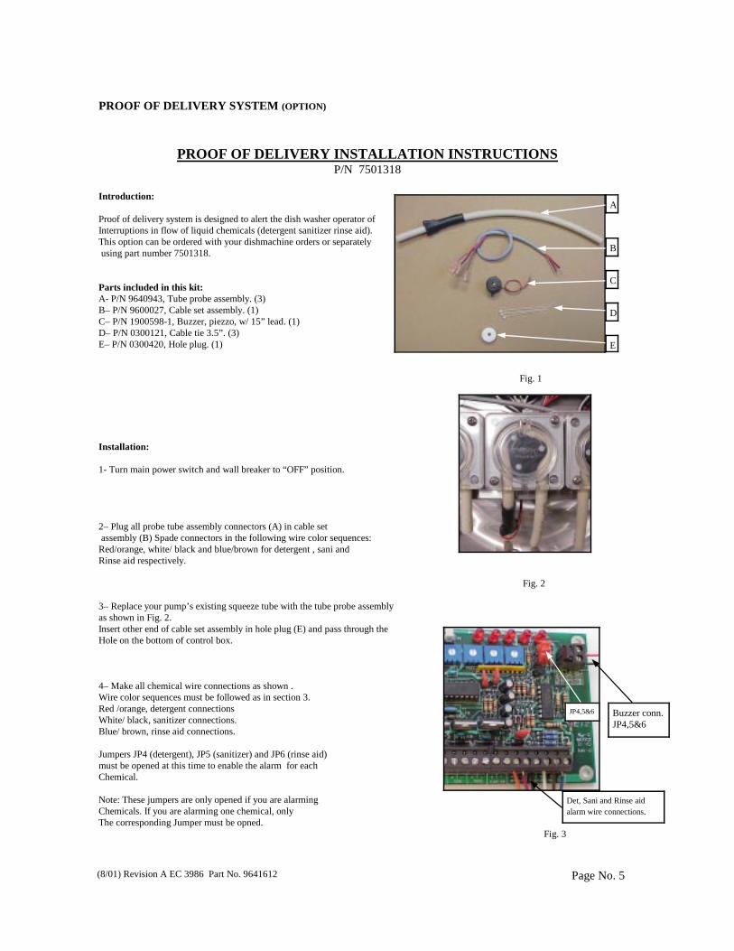
PROOF OF DELIVERY INSTALLATION INSTRUCTIONS P/N 7501318
Introduction: Proof of delivery system is designed to alert the dish washer operator of Interruptions in flow of liquid chemicals (detergent sanitizer rinse aid). This option can be ordered with your dishmachine orders or separately using part number 7501318. Parts included in this kit: A- P/N 9640943, Tube probe assembly. (3) B– P/N 9600027, Cable set assembly. (1) C– P/N 1900598-1, Buzzer, piezzo, w/ 15” lead. (1) D– P/N 0300121, Cable tie 3.5”. (3) E– P/N 0300420, Hole plug. (1) Fig. 1 Installation: 1- Turn main power switch and wall breaker to “OFF” position. 2– Plug all probe tube assembly connectors (A) in cable set assembly (B) Spade connectors in the following wire color sequences: Red/orange, white/ black and blue/brown for detergent , sani and Rinse aid respectively.
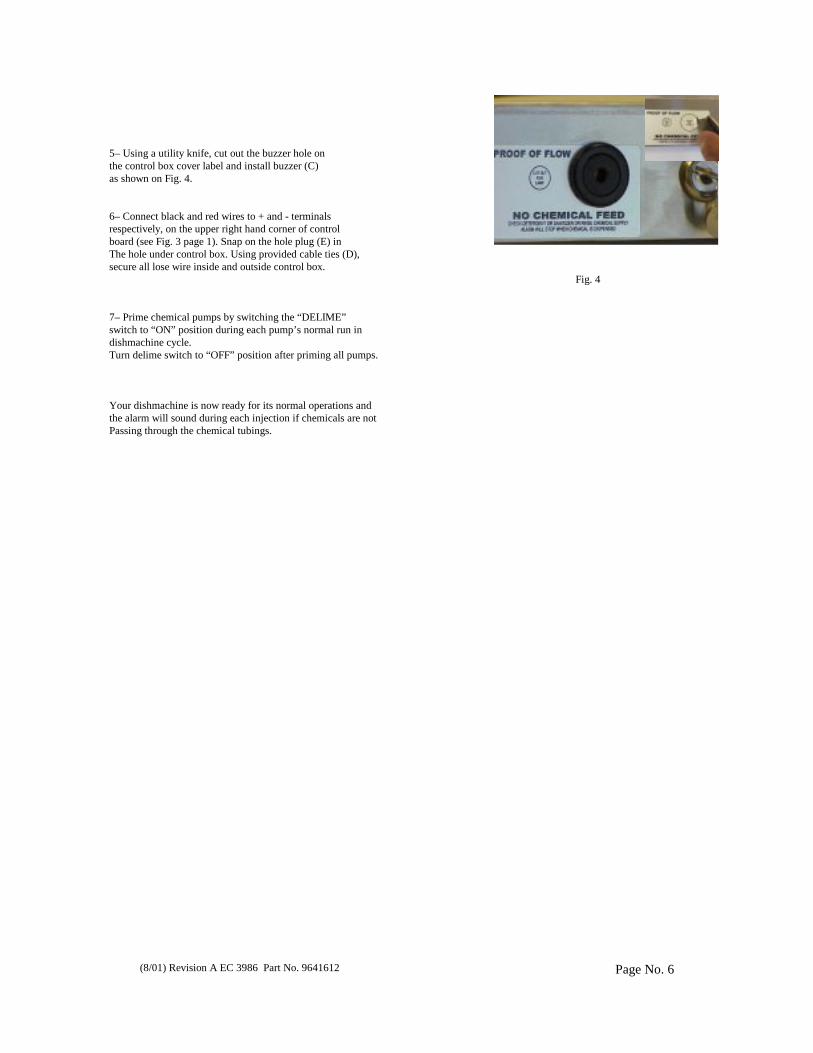
Fig. 2 3– Replace your pump’s existing squeeze tube with the tube probe assembly as shown in Fig. 2. Insert other end of cable set assembly in hole plug (E) and pass through the Hole on the bottom of control box. 4– Make all chemical wire connections as shown . Wire color sequences must be followed as in section 3. Red /orange, detergent connections White/ black, sanitizer connections. Blue/ brown, rinse aid connections. Jumpers JP4 (detergent), JP5 (sanitizer) and JP6 (rinse aid) must be opened at this time to enable the alarm for each Chemical. Note: These jumpers are only opened if you are alarming Chemicals. If you are alarming one chemical, only The corresponding Jumper must be opned.
Fig. 3
PROOF OF DELIVERY SYSTEM (OPTION)
Page No. 5 (8/01) Revision A EC 3986 Part No. 9641612
Det, Sani and Rinse aid alarm wire connections.
E
D
C
B
A
JP4,5&6 Buzzer conn.JP4,5&6
PROOF OF DELIVERY SYSTEM (IF MACHINE IS ORDERED WITH ACCESSORY KIT )
Page No. 6 (8/01) Revision A EC 3986 Part No. 9641612
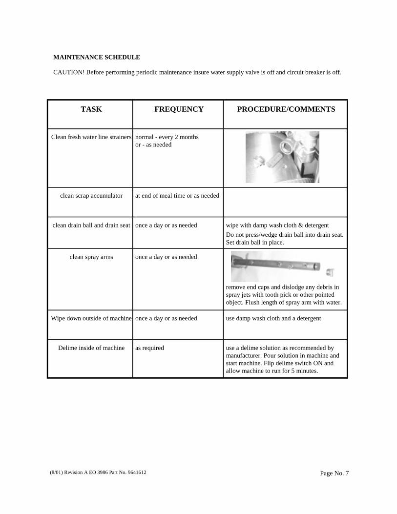
5– Using a utility knife, cut out the buzzer hole on the control box cover label and install buzzer (C) as shown on Fig. 4. 6– Connect black and red wires to + and - terminals respectively, on the upper right hand corner of control board (see Fig. 3 page 1). Snap on the hole plug (E) in The hole under control box. Using provided cable ties (D), secure all lose wire inside and outside control box. Fig. 4 7– Prime chemical pumps by switching the “DELIME” switch to “ON” position during each pump’s normal run in dishmachine cycle. Turn delime switch to “OFF” position after priming all pumps. Your dishmachine is now ready for its normal operations and the alarm will sound during each injection if chemicals are not Passing through the chemical tubings.
MAINTENANCE SCHEDULE CAUTION! Before performing periodic maintenance insure water supply valve is off and circuit breaker is off.
TASK
FREQUENCY
PROCEDURE/COMMENTS
Clean fresh water line strainers
normal - every 2 months or - as needed
clean scrap accumulator at end of meal time or as needed
clean drain ball and drain seat
once a day or as needed
wipe with damp wash cloth & detergent
Do not press/wedge drain ball into drain seat. Set drain ball in place.
clean spray arms
once a day or as needed
remove end caps and dislodge any debris in spray jets with tooth pick or other pointed object. Flush length of spray arm with water.
Wipe down outside of machine
once a day or as needed
use damp wash cloth and a detergent
Delime inside of machine
as required
use a delime solution as recommended by manufacturer. Pour solution in machine and start machine. Flip delime switch ON and allow machine to run for 5 minutes.
Page No. 7 (8/01) Revision A EO 3986 Part No. 9641612

TROUBLESHOOTING:
PROBLEM CAUSE REMEDY
Low/No spray arm pressure Impeller clogged
Pump intake tube clogged
Spray arm or spray tips clogged
Low water level
*Remove pump face and clean impeller
*Remove pump face and push debris out of pump intake tube Remove spray arm and clean
(see maintenance table Fill tank to proper level (see
initial operation)
Wash pump motor runs continuously
Delime switch is on. Faulty circuit board. Motor relay is stuck
Turn delime switch off *Call for service
Tap on relay see time setting section for relay location.
Dish washer will not start Door is open Run power switch is OFF
No supply voltage Delime switch is ON
3/8 amp fuse to transformr is blown
Replace 3/8 amp fuse
Chemical injection bad/poor (detergent, rinse, sanitizer)
Not enough chemical Poor chemical flow
Faulty chemical pump motor No chemical flow
*Adjust pot (time settings) Replace pump squeeze tube
*Replace chemical pump motor Product container empty
Leaky/noisy vacuum breaker Water pressure too low
Water pressure too high
Clean screen (see maintenance schedule)
Adjust fill pressure (see installation)
Reduced wash results Worn spray arm bearing Washer not level
Tray rails damaged
Replace bearing. Level with bullet feet (see
installation) Replace tray rails.
Dish washer will not fresh water fill Faulty solenoid valve ‘Y’strainer screen clogged
Water supply line is off
Faulty push button fill switch Fill level not set correctly
*Call for service Clean screen (see maintenance
schedule) Open supply valve *Call for service
See installation section
Dish washer will not drain Faulty drain solenoid Drain ball jammed in drain seat.
Drain/fill fuse is blown
*Call for service Open machine and lift drain ball.
Replace 2 amp slo blo fuse
Brown stains inside machine High iron content in water Delime machine to remove stains. When complete leave doors in open position to dry
inside of machine.
Page No. 8 * By authorized personnel only.
(8/01) Revision A EO 3986 Part No. 9641612

(8/01) Revision A EO 3986 Part No. 9641612 Page No. 9

DISCLAIMER Knight Inc. does not accept responsibility for the mishandling, misuse, or non-performance of the described items when used for purposes other than those specified in the instructions. For hazardous material information consult label, MSDS, or Knight Inc. WARRANTY All stainless steel components have a three year limited warranty from date of purchase against manufacturers defects. The electronic control board has a two year warranty. Warranty replacement for component parts pur-chased by Knight are limited to warranty by the manufacturer. Warranty applies only to the replacement or re-pair of such parts when returned to factory with a Knight Return Authorization (KRA) number, freight prepaid and found to be defective upon factory authorized inspection. Bearings and pump seals or rubber and synthetic rubber parts such as “O“-rings, diaphragms, squeeze tubing, and gaskets are considered expendable and are not covered under warranty. Warranty does not cover liability resulting from performance of this equipment nor the labor to replace this equipment. Product abuse or misuse voids warranty.
Page No. 10 (8/01) Revision A EO 3986 Part No. 9641612

Page No. 11 (8/01) Revision A EO 3986 Part No. 9641612
PARTS MANUAL

KLE-150GT, 120V, 60HZ PAGE 12
REV-A P/N 9641612
KLE-150GT CONTROL BOX
ASSEMBLY LIST
15
14
13
12
11
10
9
8
7
6
5
4
3
2
1
NO.
7502312
7503453
7018096
9640356
9601975
2000575
0200500
0600311
9640319
9640328
9600861
9600987
7507400
9600578
1200392
P/N
FACE PLATE CLEAR
3-LOBE ROLLER ASSY. BLUE
SQUEEZE TUBE T-53-T
ELECTRICAL BOX BODY
TEMPERATURE GAGE
TRANSFORMER TR-3040
BARRIER 3 POSITION
3/8 AMP. 240V, FUSE
CONTROL BOX COVER
NEOPRENE SWITCH GUARD
FILL/DRAIN SWITCH
MAIN SWITCH BOOT
TOGGLE SWITCH (ON/OFF)
RUBBER BOOT FOR SWITCH
LOCK & KEY
DESCRIPTION
3
3
3
1
1
1
1
1
1
1
1
1
1
1
1
QTY.
29
28
27
26
25
24
23
22
21
20
19
18
17
16
NO.
7012030
7012029
9640947
1900402
1900400
9600787
9600837
9640357-K
9640327-F
7012028
7146000
7010216
7010241
7501311
P/N
FUSE 3 AMP
FUSE 2 AMP
ELECTRICAL BOX SLIDE BASE
STRAIN RELIEF LOCKNUT
STRIAN RELIEF BODY
SWITCH, MASTER
SWITCH MOMENTARY, PUSH BUTTON
ARMORED PUSH BUTTON
COUNTER 120V (240V 96403273-F)
FUSE 1 AMP 120/250 VOLT
LTC CIRCUIT BOARD
15 RPM, 24V DC MOTOR (RINSE/SANI)
40 RPM, 24V DC MOTOR (DET.)
PUMP BODY ONLY
DESCRIPTION
1
1
1
6
6
1
1
1
1
2
1
2
1
3
QTY.

KLE-150GT, 120V, 60HZ PAGE 13
REV-A P/N 9641612
KLE-150GT DOOR ASSEMBLY PARTS
LIST
10
9
8
7
6
5
4
3
2
1
NO.
9640419
9601910
9600421
9640713
9600834
9600430
9640944-B
9640424
9640357-D
9640418
P/N
DOOR PULLER
HINGE SUPPORT PLATE
.250IDx.562OD WASHER, BRASS
DOOR PULLER SPACER
1/4-20x5/8 TRUSS HEAD
5/16 S.S. WASHER
CARRIAGE NUT 10-24
DOOR MAGNET ASSEMBLY
REED SWITCH ASSY
DOOR ASSEMBLY
DESCRIPTION
2
2
2
2
1
2
2
1
1
1
QTY.
20
19
18
17
16
15
14
13
12
11
NO.
9600781
1400462
1300490
9600437
9600641
9640955
1400476
9600843
9640944-A
9600436
P/N
WASHER S.S. 3/4" O.D.
NUT 1/4"-20 SS NYLOCK
MAGNET 1/4"X 1 1/4"
1/4"-20 ACORN NUT
1/4"-20X 1-1/4" HEX BOLT
DOOR SPRING
1/4"-20 NUT
DOOR PIVOT
CARRIAGE BOLT 10-24 X1/2"
1/4-20x1-1/2 HEX BOLT
DESCRIPTION
2
2
1
2
2
2
2
2
2
2
QTY.

KLE-150GT, 120V, 60HZ PAGE 14
REV-A P/N 9641612
KLE-150GT MACHINE CHASSIS
ASSEMBLY LIST
9
8
7
6
5
4
3
2
1
NO.
9641408
9641416
9640822
9640816
9640817
9640110
9640607
9640606
9640207
P/N
SCRAP TRAY ASSEMBLY
SCRAP TRAP ASSEMBLY
STAND UPRIGHT / EXTN
STAND LEG RIGHT SIDE
STAND LEG LEFT SIDE
PAN ASSEMBLY
TRAY RAIL LEFT
TRAY RAIL RIGHT
WRAPPER ASSEMBLY
DESCRIPTION
1
1
2
1
1
1
1
1
1
QTY.
17
16
15
14
13
12
11
10
NO.
9600017
9640712
9600835
1400462
9600421
9600423
9640952
9641418
P/N
SPLASH SHIELD
PUMP INTAKE SCREEN
1/4-20x1-1/4 BOLT, HEX HEAD
NUT, #1/4-20 W/NYLOCK
.250IDx.562OD WASHER, BRASS
1/4-20x1/2" BOLT
FRONT COVER
FRONT PANEL
DESCRIPTION
1
1
6
23
23
17
1
1
QTY.

KLE-150GT, 120V, 60HZ PAGE 15
REV-A P/N 9641612
KLE-150GT SPRAY ARMS ASSEMBLY
LIST
4
3
2
1
NO.
9600746
9600889
2300818
9641003
P/N
BOLT, HEX HEAD
NUT, 5/`6-18, S.S. #18-8
WASHER, EPDM
UPPER SPRAY ARM ASSEMBLY
DESCRIPTION
1
1
1
1
QTY.
8
7
6
5
NO.
9602207
9602205
9602210-V
9600417
P/N
BEARING SLEEVE
SPRAY ARM BEARING W/SLEEVE
SPRAY ARM OVERSIZED 20"
END CAP
DESCRIPTION
1
1
1
2
QTY.
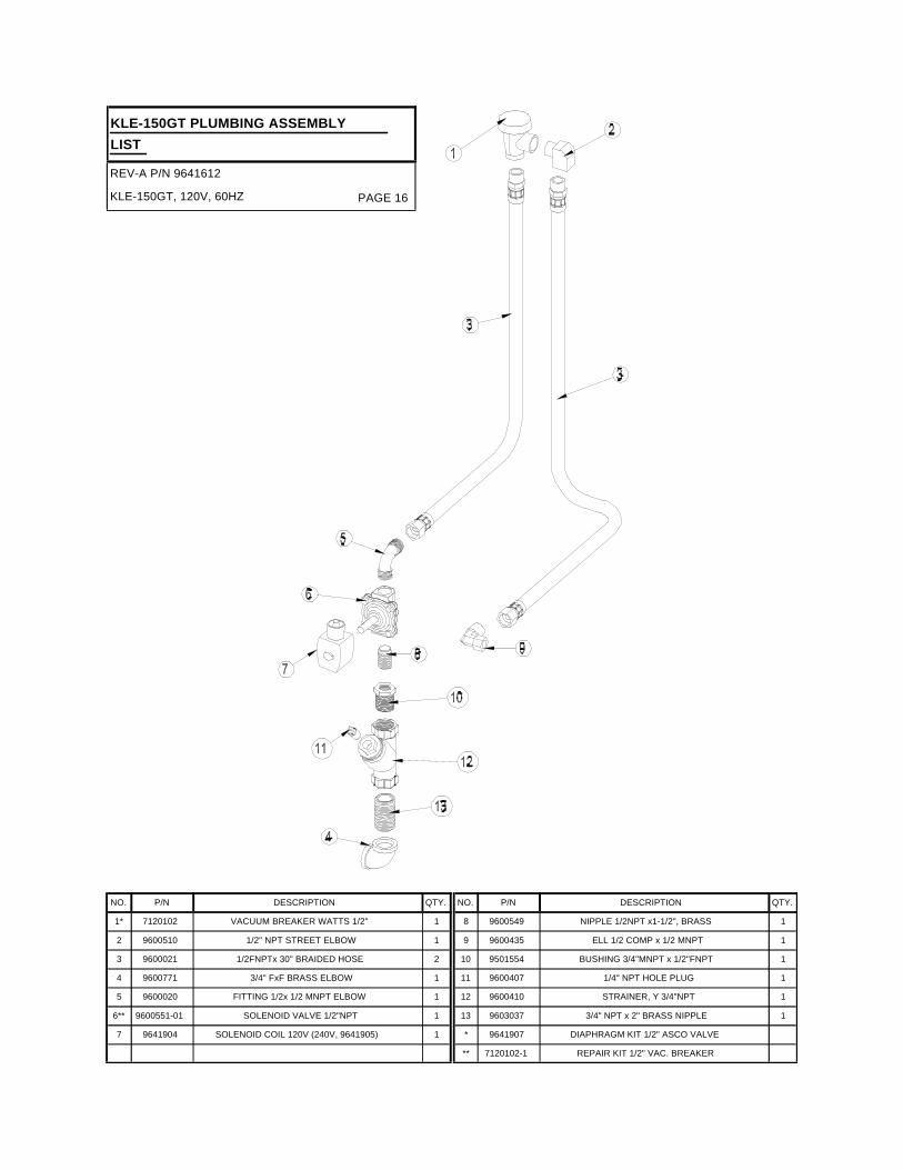
KLE-150GT, 120V, 60HZ PAGE 16
REV-A P/N 9641612
KLE-150GT PLUMBING ASSEMBLY
LIST
7
6**
5
4
3
2
1*
NO.
9641904
9600551-01
9600020
9600771
9600021
9600510
7120102
P/N
SOLENOID COIL 120V (240V, 9641905)
SOLENOID VALVE 1/2"NPT
FITTING 1/2x 1/2 MNPT ELBOW
3/4" FxF BRASS ELBOW
1/2FNPTx 30" BRAIDED HOSE
1/2" NPT STREET ELBOW
VACUUM BREAKER WATTS 1/2"
DESCRIPTION
1
1
1
1
2
1
1
QTY.
**
*
13
12
11
10
9
8
NO.
7120102-1
9641907
9603037
9600410
9600407
9501554
9600435
9600549
P/N
REPAIR KIT 1/2" VAC. BREAKER
DIAPHRAGM KIT 1/2" ASCO VALVE
3/4" NPT x 2" BRASS NIPPLE
STRAINER, Y 3/4"NPT
1/4" NPT HOLE PLUG
BUSHING 3/4"MNPT x 1/2"FNPT
ELL 1/2 COMP x 1/2 MNPT
NIPPLE 1/2NPT x1-1/2", BRASS
DESCRIPTION
1
1
1
1
1
1
QTY.

KLE-150GT, 120V, 60HZ PAGE 17
REV-A P/N 9641612
KLE-150GT DRAIN BALL SOLENOID
LINK ASSEMBLY PARTS LIST
7
6
5
4
3
2
1
NO.
1900616
1900738
9641516
9600444-1
9641506
9641519
9641518
P/N.
#8-32 X 5/8 SCREW
#6-32X3/4, PAN HEAD SCREW
DRAIN LIFTING ARM GUIDE
DRAIN SOLENOID 120V/60HZ (240V, 9600454)
DRAIN BALL
DRAIN BALL STEM
DRAIN LIFTING ARM
DESCRIPTION
1
1
1
1
1
1
1
QTY.
14
13
12
11
10
9
8
NO.
1400476
1400462
9640944-A
9640944-B
9603065
1400461
9600641
P/N.
NUT, 1/4-20, S.S.
NUT W/NYLOCK, #1/4-20
CARRIAGE BOLT 10-24 X 1/2 IN
KEPS NUT 10-24 SS
#6-32 NYLOCK NUT
NUT W/NYLOCK #8-32, S.S
1/4-20 X 1-1/4 BOLT, HEX HEAD
DESCRIPTION
4
4
3
3
1
1
4
QTY.
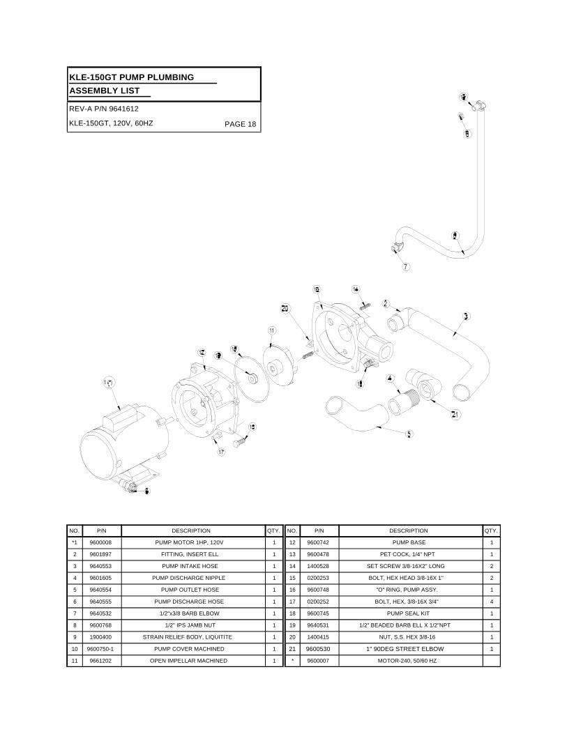
KLE-150GT, 120V, 60HZ PAGE 18
REV-A P/N 9641612
KLE-150GT PUMP PLUMBING
ASSEMBLY LIST
11
10
9
8
7
6
5
4
3
2
*1
NO.
9661202
9600750-1
1900400
9600768
9640532
9640555
9640554
9601605
9640553
9601897
9600008
P/N
OPEN IMPELLAR MACHINED
PUMP COVER MACHINED
STRAIN RELIEF BODY, LIQUITITE
1/2" IPS JAMB NUT
1/2"x3/8 BARB ELBOW
PUMP DISCHARGE HOSE
PUMP OUTLET HOSE
PUMP DISCHARGE NIPPLE
PUMP INTAKE HOSE
FITTING, INSERT ELL
PUMP MOTOR 1HP, 120V
DESCRIPTION
1
1
1
1
1
1
1
1
1
1
1
QTY.
*
21
20
19
18
17
16
15
14
13
12
NO.
9600007
9600530
1400415
9640531
9600745
0200252
9600748
0200253
1400528
9600478
9600742
P/N
MOTOR-240, 50/60 HZ
1" 90DEG STREET ELBOW
NUT, S.S. HEX 3/8-16
1/2" BEADED BARB ELL X 1/2"NPT
PUMP SEAL KIT
BOLT, HEX, 3/8-16X 3/4"
"O" RING, PUMP ASSY.
BOLT, HEX HEAD 3/8-16X 1"
SET SCREW 3/8-16X2" LONG
PET COCK, 1/4" NPT
PUMP BASE
DESCRIPTION
1
1
1
1
4
1
2
2
1
1
QTY.