96 continental
TRANSCRIPT

1996CONTINENTAL
Your satisfaction is our #1 goal. If you havequestions or concerns with your vehicle, we suggestyou follow these steps:
I . Contact your Sales Representative or ServiceAdvisor at your selling/servicing dealership.
2. If the inquiry or concern remains unresolved,contact the Sales Manager or Service Managerat the dealership.
3. If the inquiry or concern cannot be resolved atthe dealership level, please contact the FordCustomer Assistance Center.
In the United States:
Ford Motor CompanyLincoln Customer Assistance Center
300 Renaissance CenterP.O. Box 43360
Detroit, MI 482431-800-521-4140
TDD for the hearing impaired: 1-800-232-5952
In Canada:
The Lincoln CentreFord Motor Company of Canada, Limited
P.O. Box 1580, Station BMississauga, Ontario L4Y 4G3
1-800-387-9333
Outside the U.S. or Canada:FORD MOTOR COMPANY EXPORT OPERATIONS
1555 Fairlane DriveFairlane Business Park #3
Allen Park, Michigan 481 01Telephone (313) 594-4857
Fax (313) 390-0804
All rights reserved. Reproduction by anymeans, electronic or mechanical, includingphotocopying, recording, or by anyinformation storage and retrieval system ortranslation in whole or part is not permittedwithout written authorization from FordMotor Company.
Copyright @ 1995, Ford Motor Company
Table of Contents
INTRODUCTORY INFORMATION
SAFETY RESTRAINTS
STARTING YOUR CONTINENTAL
WARNING LIGHTS AND GAUGES
INSTRUMENT PANEL CONTROLS
STEERING COLUMN CONTROLS
FEATURES
ELECTRONIC SOUND SYSTEMS
1
9
41
51
69
89
99
159
i
DRIVING YOUR CONTINENTAL
ROADSIDE EMERGENCIES
CUSTOMER ASSISTANCE
ACCESSORIES
SERVICING YOUR CONTINENTAL
QUICK INDEX
INDEX
GAS STATION INFORMATION
179
199
213
223
231
299
307
322
iii
Introductory InformationFord's Commitment to YouAt Ford Motor Company, excellence is thecontinuous commitment to achieve the best resultpossible. It is dedication to learning what you want,determination to develop the right concept, andexecution of that concept with care, precision, andattention to detail. In short, excellence means beingthe standard by which others are judged.
Our Guiding Principles
Quality comes first. For your satisfaction, thequality of our products and services must be ournumber one priority.
You are the focus of everything we do. Ourwork must be done with you in mind, providingbetter products and services than ourcompetition.
Continuous improvement is essential to oursuccess. We must strive for excellence ineverything we do: in our products - in their safetyand value - and in our services, our human relations,our competitiveness, and our profitability.
Employee involvement is our way of life. We area team. We must treat one another with trust andrespect.
Dealers and suppliers are our partners. We mustmaintain mutually beneficial relationships withdealers, suppliers, and our other businessassociates.
Integrity is never compromised. Our conductworldwide must be pursued in a manner that issocially responsible and commands respect for itsintegrity and for its positive contributions tosociety
1
Things to Know About UsingThis GuideCongratulations on the purchase of your newvehicle. This guide has information about theequipment and the options for your new vehicle.You may not have bought all of the optionsavailable to you. If you do not know whichinformation applies to your vehicle, talk to yourdealer.
This guide describes equipment and gives
specifications for equipment that was in effect whenthis guide was approved for printing. Ford maydiscontinue models or change specifications ordesign without any notice and without incurringobligation.
2
NOTES and WARNINGSNOTES give you additional information about the subjectmatter you are referencing.
WARNINGS remind you to be especially careful in thoseareas where carelessness can cause damage to your vehicle orpersonal injury to yourself, your passengers or other people.Please read all WARNINGS carefully.
/!\ WARNING
Finding Information in This GuideAfter you have read this guide once, you will probably returnto it when you have a specific question or need additionalinformation. To help you find specific information quickly,you can use the Quick Index or the Index.
The Quick Index at the end of the book provides apage number following each item which indicateswhere detailed information can be found.
To use the Index, turn to the back of the book andsearch in the alphabetical listing for the word thatbest describes the information you need. If the wordyou chose is not listed, think of other related wordsand look them up. We have designed the Index sothat you can find information under a technicalterm.
Canadian Owners - French VersionFrench Owner Guides can be obtained from yourdealer or by writing to Ford Motor Company ofCanada, Limited, Service Publications, P.O. Box1580, Station B, Mississauga, Ontario L4Y 4G3.
The Lincoln CommitmentThe Lincoln Commitment is more than the prestige of owninga superior luxury automobile, it is a comprehensive ownerbenefits package that is designed to provide you with servicesto support your every driving need.
The following is a brief explanation of the LincolnCommitment benefits. We encourage you to learn aboutthese benefits and take full advantage of them. Detailedinformation on all of these benefits will be sent to youapproximately 25 days after you have taken delivery of yourvehicle.
Service LoanerShould your Lincoln require overnight warranty service, yourdealership will provide you with a service loaner car, whenavailable, or a rental allowance of up to $30 a day for up tofive days.
3
Roadside Service AssistanceLincoln owners receive complimentary 24-houremergency roadside service assistance for a period offour years for towing, jump-starting, lock-out service,gas delivery, a tire change or other roadside services.Call the hotline at 1-800-521-4140 any time of day ornight for emergency roadside assistance.
Emergency Travel ExpenseReimbursementCovers expenses such as meals, lodging and carrental if your automobile is disabled more than 100miles (160 km) from home.
Destination Assistance (U.S. only)In the event of a collision or mechanical breakdown,Lincoln helps get you to your immediate destinationwith a reimbursement allowance for emergencytransportation service such as taxicabs, rental cars,shuttles, etc.
4
Trip Planning ServicePlan your journeys with custom-computerized,travel-related information including maps and triproutings. To order customer-designed travel packets,call 1-800-521-4140.
Membership in Quest International(U.S. only)You will automatically receive a complimentarymembership in Quest International which entitiesyou to travel-related discounts on meals and roomsat more than 2,100 hotels in the United States,Canada, Mexico and the Caribbean.
The Lincoln WarrantyFor specifics on what is covered, see your WarrantyInformation Booklet.
Lincoln Customer Assistance CenterIf you have questions regarding your Lincoln or theLincoln Commitment, call our Customer AssistanceCenter:
United States 1-800-521-4140
Canada 1-800-387-9333
You may call the Customer Assistance Center,Monday through Friday, 8 a.m. to 5 p.m. in all timezones.
Owner Identification CardPersonalized with your name and vehicleidentification number as well as the hotline numberto call for customer service or roadside assistanceservice.
Your Maintenance Schedule andRecord BookletThe Maintenance Schedule and Record booklet liststhe services that are most important for keepingyour vehicle in good condition. A record log is alsoprovided to help you keep track of all servicesperformed.
About the WarrantiesYour vehicle is covered by three types of warranties:Basic Vehicle Warranty, Extended Warrantieson certain parts, and Emissions Warranties.
Read your Warranty Information Booklet carefully tofind out about your vehicle's warranties and yourbasic rights and responsibilities.
If you lose your Warranty Information Booklet, youcan get a new one free of charge. Contact any Fordor Lincoln-Mercury dealer, or refer to the addressesand phone numbers on the first page of this ownerguide.
5
Buying a Ford Extended Service PlanIf you bought your vehicle in the U.S., you can buya Ford Extended Service Plan for your vehicle. Thisoptional contract provides service protection for alonger period of time than the basic warranty thatcomes with your vehicle.
You do not have to buy this option when you buyyour vehicle. However, your option to purchase theFord Extended Service Plan runs out after 18months or 18,000 miles. See your dealer for moredetails about the Ford Extended Service Plan.
If you purchased a Canadian vehicle and did nottake advantage of the Ford Extended Service Plan atthe time of purchase, you may still be eligible. Seeyour dealer for the details.
6
Breaking Your Vehicle InYour new vehicle goes through an adjustment orbreak-in period during the first 1,000 miles(1,600 km) that you drive it. During the break-inperiod, you need to pay careful attention to howyou drive your vehicle.
Avoid sudden stops. Because your vehicle hasnew brake linings, you should take these steps:
-Watch traffic carefully so that you can anticipate when to stop.
-Begin braking well in advance.
-Apply the brakes gradually.
The break-in period for new brake linings lastsfor I 00 miles (I 60 km) of city driving or 1,000miles (1,600 km) of highway driving.
Use only the type of engine oil that Fordrecommends. See Engine oil recommendationsin the Index. Do not use special "break-in" oils.
Cleaning the Outside of YourVehicle
Washing and Polishing Your VehicleWash the outside of your vehicle, including theunderside, with a mild detergent.
DO NOT:
Wash your vehicle with hot water
Wash your vehicle while it sits in directsunlight
Wash your vehicle while the body is hot
Pollen, bird droppings a . nd tree sap can damagethe paint, especially in hot weather. Wash yourvehicle as often as necessary to keep it clean.
Take similar precautions if your vehicle isexposed to chemical industrial fallout.
Paint damage resulting from fallout is not relatedto a defect in paint materials or workmanship andtherefore is not covered by warranty. Ford,however, believes that continual improvement incustomer satisfaction is a high priority. For thisreason, Ford has authorized its dealers to repair,at no charge to the owner, the surfaces of newvehicles damaged by environmental fallout within12 months or 12,000 miles (20,000 km) ofpurchase, whichever comes first. Customers maybe required to bring their vehicle in for inspectionby a Ford representative.
Polish your vehicle to remove harmful depositsand protect the finish.
7
Cleaning Chrome and Aluminum PartsWash chrome and aluminum parts with a milddetergent. Do not use steel wool, abrasive cleaners,fuel, or strong detergents.
8
Cleaning Plastic PartsSome of your vehicle's exterior trim parts are plastic. Cleanwith a tar and road oil remover if necessary. Use a vinylcleaner for routine cleaning.
Do not clean plastic parts with thinners, solvents orpetroleum-based cleaners.
If you have your vehicle rustproofed, remove oversprayedrustproofing with a tar and road oil remover. If rustproofingis not removed from plastic and rubber parts, it can causedeterioration.
Safety RestraintsImportant Safety Belt InformationThe use of safety belts helps to restrain you andyour passengers in case of a collision. In moststates and in Canada the law requires their use.
Safety belts provide best restraint when:
the seatback is upright
the occupant is sitting upright (not slouched)
the lap belt is snug and low on the hips
the shoulder belt is snug against the chest
the knees are straight forward
To help you remember to fasten your safety belt, a
warning light may come on and a chime may sound.See Safety Belt Warning Light and Chime in theWarning Lights and Gauges chapter.
See the following sections in this chapter fordirections on how to properly use these safety belts.Also see Safety Restraints for Children in thischapter for special instructions about using safetybelts for children.
/!\ WARNING
Make sure that you and your passengers wearsafety belts. Always drive and ride with yourseatback upright and the lap belt snug and lowacross the hips.
9
/!\ WARNINGNever wear the shoulder belt under thearm. Never swing it around the neck overthe inside shoulder. Never use a single beltfor more than one person or across morethan one seating position. Each seatingposition in your vehicle has a specific safetybelt assembly which is made up of onebuckle and one tongue that are designed tobe used as a pair. Failure to follow theseprecautions could increase the risk and/orseverity of injury in a collision.
/!\ WARNING
Never drive or ride with a twisted orjammed safety belt. If you cannot untwistor unjam the safety belt, see the nearestqualified technician immediately.
10
/!\WARNING
To reduce the risk of serious injury in acollision, children should always ride withthe seatback upright.
/!\WARNING
Never let a passenger hold a child on his orher lap while the vehicle is moving. Thepassenger cannot protect the child frominjury in a collision.
Lock the doors of your vehicle before driving to lessenthe risk of the door coming open in a collision.
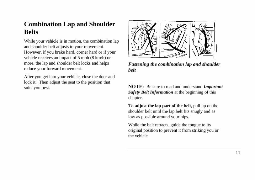
Combination Lap and ShoulderBeltsWhile your vehicle is in motion, the combination lapand shoulder belt adjusts to your movement.However, if you brake hard, corner hard or if yourvehicle receives an impact of 5 mph (8 km/h) ormore, the lap and shoulder belt locks and helpsreduce your forward movement.
After you get into your vehicle, close the door andlock it. Then adjust the seat to the position thatsuits you best.
Fastening the combination lap and shoulderbelt
NOTE: Be sure to read and understand ImportantSafety Belt Information at the beginning of thischapter.
To adjust the lap part of the belt, pull up on theshoulder belt until the lap belt fits snugly and aslow as possible around your hips.
While the belt retracts, guide the tongue to itsoriginal position to prevent it from striking you orthe vehicle.
11
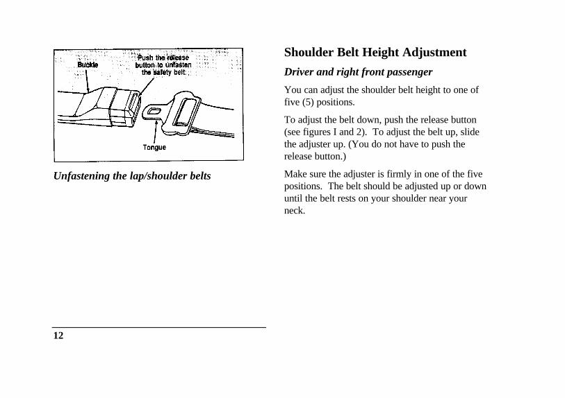
Unfastening the lap/shoulder belts
12
Shoulder Belt Height Adjustment
Driver and right front passenger
You can adjust the shoulder belt height to one offive (5) positions.
To adjust the belt down, push the release button(see figures I and 2). To adjust the belt up, slidethe adjuster up. (You do not have to push therelease button.)
Make sure the adjuster is firmly in one of the fivepositions. The belt should be adjusted up or downuntil the belt rests on your shoulder near yourneck.
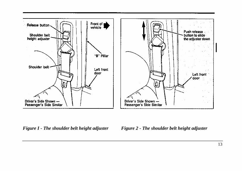
Figure I - The shoulder belt height adjuster Figure 2 - The shoulder belt height adjuster
13
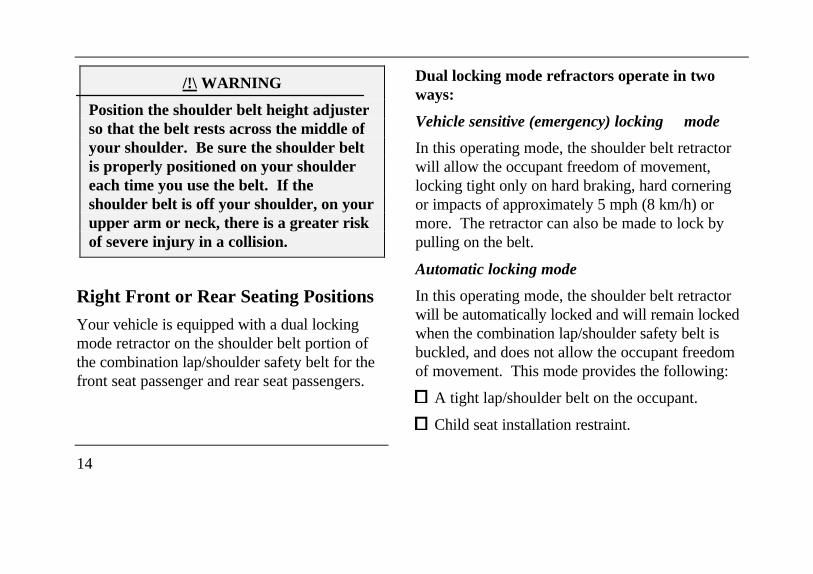
/!\ WARNING
Position the shoulder belt height adjusterso that the belt rests across the middle ofyour shoulder. Be sure the shoulder beltis properly positioned on your shouldereach time you use the belt. If theshoulder belt is off your shoulder, on yourupper arm or neck, there is a greater riskof severe injury in a collision.
Right Front or Rear Seating Positions
Your vehicle is equipped with a dual lockingmode retractor on the shoulder belt portion ofthe combination lap/shoulder safety belt for thefront seat passenger and rear seat passengers.
14
Dual locking mode refractors operate in twoways:
Vehicle sensitive (emergency) locking mode
In this operating mode, the shoulder belt retractorwill allow the occupant freedom of movement,locking tight only on hard braking, hard corneringor impacts of approximately 5 mph (8 km/h) ormore. The retractor can also be made to lock bypulling on the belt.
Automatic locking mode
In this operating mode, the shoulder belt retractorwill be automatically locked and will remain lockedwhen the combination lap/shoulder safety belt isbuckled, and does not allow the occupant freedomof movement. This mode provides the following:
A tight lap/shoulder belt on the occupant.
Child seat installation restraint.
/!\ WARNING
Rear facing infant seats should never beplaced in the front seat.
This mode must be used when installing a childseat on the front passenger seat and rear seatswhere dual locking refractors are provided. Toswitch the retractor from the emergency lockingmode to the automatic locking mode, performthe following steps:
1. Buckle the lap/shoulder combination belt.
2. Grasp the shoulder portion of the belt andpull downward until all of the belt isextracted and a click is heard. At this time,the retractor is in the automatic lockingmode (child restraint mode).
3. A clicking sound will contnue to be heard asthe belt is allowed to retract.
NOTE: When the combinationlap/shoulder belt is unbuckled and allowed toretract completely, the retractor will switch tothe vehicle sensitive (emergency) locking mode.See the detailed instructions under Safety Seatsfor Children in this chapter.
Lap Belts
The lap belt in the center of the front seat doesnot adjust automatically. You must adjust it tofit snugly and as low as possible around yourhips. Do not wear it around your waist.
15
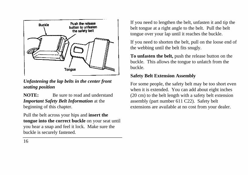
Unfastening the lap belts in the center frontseating position
NOTE: Be sure to read and understandImportant Safety Belt Information at thebeginning of this chapter.
Pull the belt across your hips and insert thetongue into the correct buckle on your seat untilyou hear a snap and feel it lock. Make sure thebuckle is securely fastened.
16
If you need to lengthen the belt, unfasten it and tip thebelt tongue at a right angle to the belt. Pull the belttongue over your lap until it reaches the buckle.
If you need to shorten the belt, pull on the loose end ofthe webbing until the belt fits snugly.
To unfasten the belt, push the release button on thebuckle. This allows the tongue to unlatch from thebuckle.
Safety Belt Extension Assembly
For some people, the safety belt may be too short evenwhen it is extended. You can add about eight inches(20 cm) to the belt length with a safety belt extensionassembly (part number 611 C22). Safety beltextensions are available at no cost from your dealer.
on the label. Also, use the safety belt extensiononly if the safety belt is too short for you whenfully extended. Do not use extension to change thefit of the shoulder belt across the torso.
/!\ WARNING
Failure to follow these instructions will affectthe performance of the safety belts andincrease the risk of personal injury.
Safety Belt MaintenanceCheck the safety belt systems periodically to makesure that they work properly and are not damaged.
All safety belt assemblies, including refractors,buckles, front seat belt buckle support assemblies(slide bar) (if equipped), child safety seat tetherbracket assemblies (if equipped), and attachinghardware, should be inspected after any collision.Ford recommends that all safety belt assemblies usedin vehicles involved in a collision be replaced.
However, if the collision was minor and a qualifiedtechnician finds that the belts do not show damageand continue to operate properly, they do not need tobe replaced. Safety belt assemblies not in use duringa collision should also be inspected and replaced ifeither damage or improper operation is noted.
Cleaning the Safety Belts
Clean the safety belts with any mild soap solution thatis recommended for cleaning upholstery or carpets.Do not bleach or dye the belt webbing because thismay weaken it.
Air Bag Supplemental RestraintSystem (SRS)The driver and right front passenger air bags areSupplemental Restraint Systems (SRS), provided atthese seating positions in addition to the
lap/shoulder belt, and are designed to supplement theprotection provided to properly belted occupants
17
in moderate to severe frontal collisions. Thesupplemental air bag system does not providerestraint to the lower body.
/!\WARNING
The supplemental air bags are not designedto protect occupants in the front centerseating position.
The Importance of Wearing Safety Belts
/!\WARNING
Safety belts must be worn by all vehicleoccupants to be properly restrained andhelp reduce the risk of injury in a collision.
18
/!\ WARNINGAll occupants of the vehicle, including thedriver, should always wear their safetybelts, even when an air bag SupplementalRestraint System is provided.
There are four very important reasons to usesafety belts even with an air bag system. Useyour safety belts to:
help keep you in the proper position (awayfrom the air bag) when it inflates
reduce the risk of harm in rollover, side orrear impact collisions, because an air bag isnot designed to inflate in such situations
reduce the risk of harm in frontal colflsionsthat are not severe enough to activate thesupplemental air bag
reduce the risk of being thrown from yourvehicle
The Importance of Being ProperlySeated
In a collision, the air bag must inflate extremelyfast to help provide additional protection foryou. In order to do this, the air bag must inflatewith considerable force. If you are not seated ina normal riding position with your back againstthe seatback, the air bag may not protect youproperly and could possibly hurt you as itinflates.
/!\ WARNING
If a passenger is not properly seated andrestrained, an inflating air bag couldcause serious injury.
In rear-facing infant seats, the infant's head is closerto the air bag. The force of the rapidly inflating airbag could push the top of the rear-facing seatagainst the vehicle seatback or center armrests (if soequipped), or center console (if so equipped).
Children weighing less than 40 lbs. (18 kg.) shoulduse child or infant seats. Forward facing child seatsmust have the passenger seat moved as far backfrom the instrument panel as possible.
Your vehicle is equipped with a right frontpassenger air bag. Front passengers, especiallychildren and small adults, should never sit on theedge of the seat, stand near the glove compartmentof the instrument panel, or lean over with theirfaces near the glove compartment when the vehicleis moving. All occupants should sit with their backsagainst the seatback and use the safety belts.
19
/!\ WARNING
REAR-FACING INFANT SEATSSHOULD NEVER BE USED IN THEFRONT SEAT. REAR-FACINGINFANT SEATS MUST ALWAYS BEPLACED IN THE REAR SEAT. Failureto follow these instructions could result inserious injury.
/!\ WARNING
Do not place objects or mount equipmenton or near the air bag cover on thesteering wheel or in front seat areas thatmay come in contact with a deploying airbag. Failure to follow this instructionmay increase the risk of personal injury inthe event of a collision.
20
For further information about the proper mountingof equipment in the front seat of this vehicle, pleaserefer to Ford's brochure entitled Some ImportantInformation About Air Bag Supplemental RestraintSystem which can be obtained by calling Helm Inc.at 1-800-782-4356. Ask for brochure FPS-8602.
For additional important safety information on theproper use of seat belts, child seats, and infant seats,please read the other sections of this part of theOwner Guide, especially sections entitled SafetyBelts for Children and Safety Seats for Children.
How the Air Bag Supplemental RestraintSystem Operates
The Air Bag Supplemental Restraint Systemconsists of the Driver and Passenger air bags,impact sensors, a system diagnostic module, areadiness light and tone, and the electrical wiringwhich connects the components.
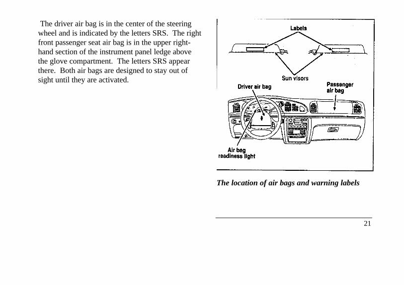
The driver air bag is in the center of the steeringwheel and is indicated by the letters SRS. The rightfront passenger seat air bag is in the upper right-hand section of the instrument panel ledge abovethe glove compartment. The letters SRS appearthere. Both air bags are designed to stay out ofsight until they are activated.
The location of air bags and warning labels
21
If a collision occurs, the sensors sense theseverity of the impact and activates the air bagsif necessary. The air bag system is designed todeploy in frontal and front-angled collisionsmore severe than hitting a parked vehicle (ofsimilar size and weight) head-on at about 28mph (45 km/h). Because the system senses thecrash severity rather than vehicle speed, somefrontal collisions at speeds above 28 mph (45km/h) will not inflate the air bag.
22
When the sensors activate the system, the air bagsinflate rapidly, filling with non-toxic nitrogen gas ina fraction of a second. Immediately after inflation,the air bags deflate by releasing the nitrogen gasthrough vent holes. The whole process takes placein a matter of seconds.
/!\ WARNING
Air bag system components get hot afterinflation. Do not touch them after inflation.
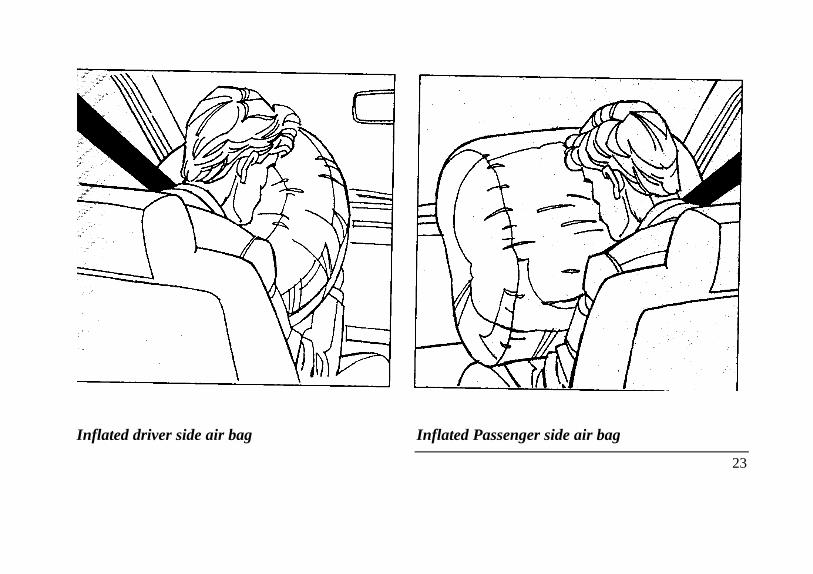
Inflated driver side air bag Inflated Passenger side air bag
23
/!\ WARNING
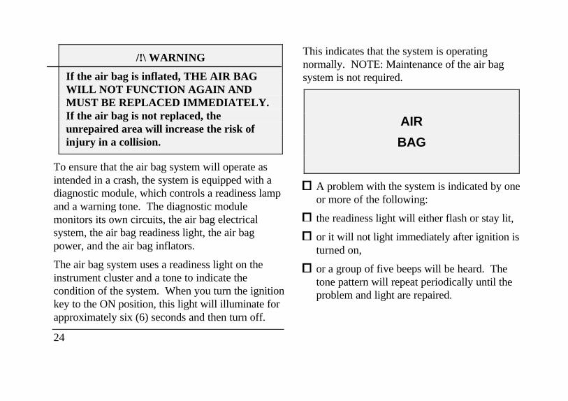
If the air bag is inflated, THE AIR BAGWILL NOT FUNCTION AGAIN ANDMUST BE REPLACED IMMEDIATELY.If the air bag is not replaced, theunrepaired area will increase the risk ofinjury in a collision.
To ensure that the air bag system will operate asintended in a crash, the system is equipped with adiagnostic module, which controls a readiness lampand a warning tone. The diagnostic modulemonitors its own circuits, the air bag electricalsystem, the air bag readiness light, the air bagpower, and the air bag inflators.
The air bag system uses a readiness light on theinstrument cluster and a tone to indicate thecondition of the system. When you turn the ignitionkey to the ON position, this light will illuminate forapproximately six (6) seconds and then turn off.
24
This indicates that the system is operatingnormally. NOTE: Maintenance of the air bagsystem is not required.
AIR
BAG
A problem with the system is indicated by oneor more of the following:
the readiness light will either flash or stay lit,
or it will not light immediately after ignition isturned on,
or a group of five beeps will be heard. Thetone pattern will repeat periodically until theproblem and light are repaired.
If any of these things happen, have the air bagsystem serviced at your Ford or Lincoln-Mercury dealer immediately. Unless serviced,the air bag supplemental restraint system maynot function properly in the event of a collision.
/!\ WARNING
Do not attempt to service, repair, or modifythe Air Bag Supplemental Restraint Systemor its fuses. See your Ford or Lincoln-Mercury dealer.
Disposal of air bags or air bag equippedvehicles
For disposal of air bags or air bag equippedvehicles, see your local Ford or Lincoln-Mercurydealer. Air bags MUST be disposed of by qualifiedpersonnel.
Safety Restraints for ChildrenIn the U.S. and Canada, you are required bylaw to use safety restraints for children. Ifsmall children ride in your vehicle - thisgenerally includes children who are four yearsold or younger and who weigh 40 pounds (18kg) or less - you must put them in safety seatsthat are made specially for children. Safetybelts alone do not provide maximum protectionfor these children. Check your local and statelaws for specific requirements.
/!\ WARNING
Never let a passenger hold a child on his orher lap while the vehicle is moving. Thepassenger cannot protect the child frominjury in a collision.
25
/!\ WARNING
Passengers should not be allowed to ride inthe cargo area. Persons not riding in a seatwith a fastened seat belt are much more likelyto suffer serious injury in a collision. Cargoshould always be secured to prevent it fromshifting and causing damage to the vehicle orharm to passengers.
When possible, put children in the rear seat, ofyour vehicle. Accident statistics suggest thatchildren are safer when properly restrained in therear seating positions than in the front seatingpositions.
26
/!\ WARNING
Carefully follow all of the manufacturer'sinstructions included with the safety seat youput in your vehicle. if you do not install and usethe safety seat properly, the child may beinjured in a sudden stop or collision.
/!\ WARNING
Safety belts and seats can become hot in avehicle that has been closed up in sunnyweather; they could bum a small child. Checkseat covers and buckles before you place a childanywhere near them.
/!\ WARNING
Never leave a child unattended in your vehicle.
Safety Seats for Children
Use a safety seat that is recommended for the sizeand weight of the child. Always follow the safetyseat manufacturer's instructions when installingand using the safety seat.
Ford recommends the use of a child safety seathaving a top tether strap. Install the child safetyseat in a seating position which is capable ofproviding a tether anchorage. For moreinformation on top tether straps see AttachingSafety Seats With Tether Straps in this chapter.
When installing a child safety seat, be sure to usethe correct safety belt buckle for that seatingposition, and make sure the tongue is securelyfastened in the buckle.
/!\WARNING
REAR-FACING INFANT SEATSSHOULD NEVER BE USED IN THEFRONT SEAT. REAR-FACING INFANTSEATS MUST ALWAYS BE PLACED INTHE REAR SEAT. Failure to follow theseinstructions could result in serious injury.
When using forward-facing child seats inthe front seat, always move the passengerseat as far back from the instrument panelas possible. Failure to follow thesewarnings could result in injury to thechild.
All child restraint systems are designed to besecured in vehicle seats by lap belts or by the lapportion of a lap-shoulder belt.
27
/!\WARNING
If you do not properly secure the safetyseat, the child occupying the seat may beinjured during a collision or sudden stop.An unsecured safety seat could also injureother passengers.
/!\WARNING
Carefully follow all of the manufacturer'sinstructions included with the safety seatyou put in your vehicle. If you do notinstall and use the safety seat properly, thechild may be injured in a sudden stop orcollision.
28
/!\WARNING
Always keep the buckle release buttonpointing upward and away from the childseat, with the tongue between the child seatand the release button as shown in thefollowing illustration.
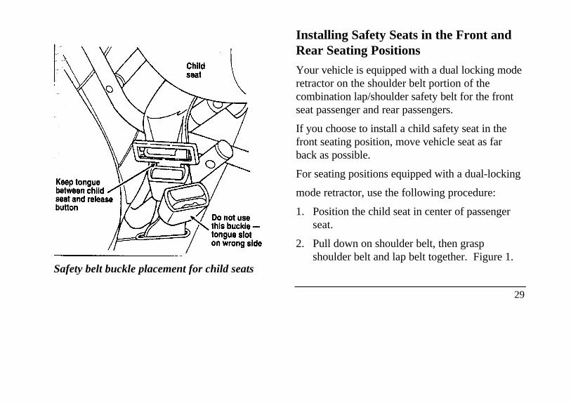
Safety belt buckle placement for child seats
Installing Safety Seats in the Front andRear Seating Positions
Your vehicle is equipped with a dual locking moderetractor on the shoulder belt portion of thecombination lap/shoulder safety belt for the frontseat passenger and rear passengers.
If you choose to install a child safety seat in thefront seating position, move vehicle seat as farback as possible.
For seating positions equipped with a dual-locking
mode retractor, use the following procedure:
1. Position the child seat in center of passengerseat.
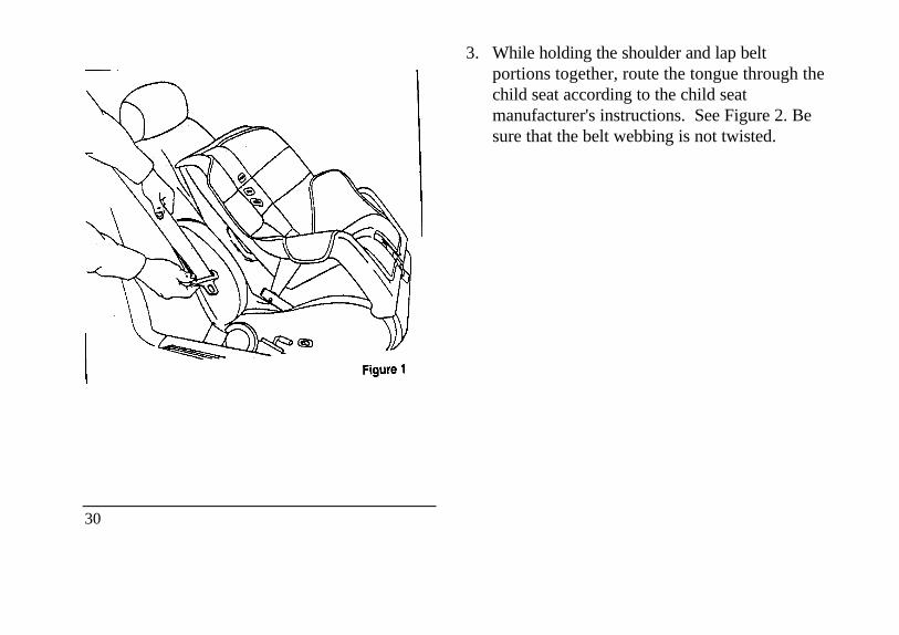
2. Pull down on shoulder belt, then graspshoulder belt and lap belt together. Figure 1.
29
30
3. While holding the shoulder and lap beltportions together, route the tongue through thechild seat according to the child seatmanufacturer's instructions. See Figure 2. Besure that the belt webbing is not twisted.
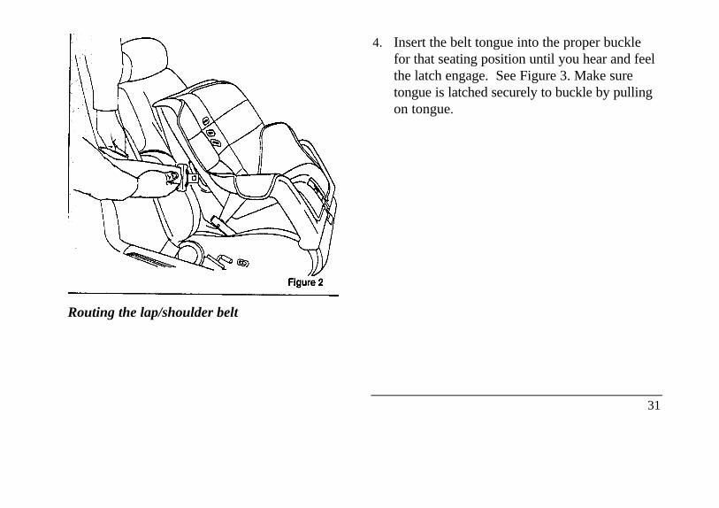
Routing the lap/shoulder belt
4. Insert the belt tongue into the proper bucklefor that seating position until you hear and feelthe latch engage. See Figure 3. Make suretongue is latched securely to buckle by pullingon tongue.
31
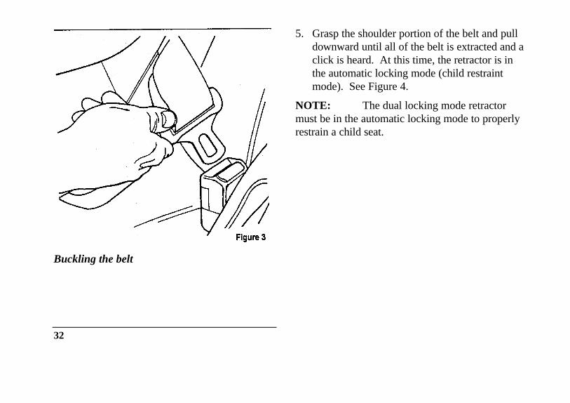
Buckling the belt
32
5. Grasp the shoulder portion of the belt and pulldownward until all of the belt is extracted and aclick is heard. At this time, the retractor is inthe automatic locking mode (child restraintmode). See Figure 4.
NOTE: The dual locking mode retractormust be in the automatic locking mode to properlyrestrain a child seat.
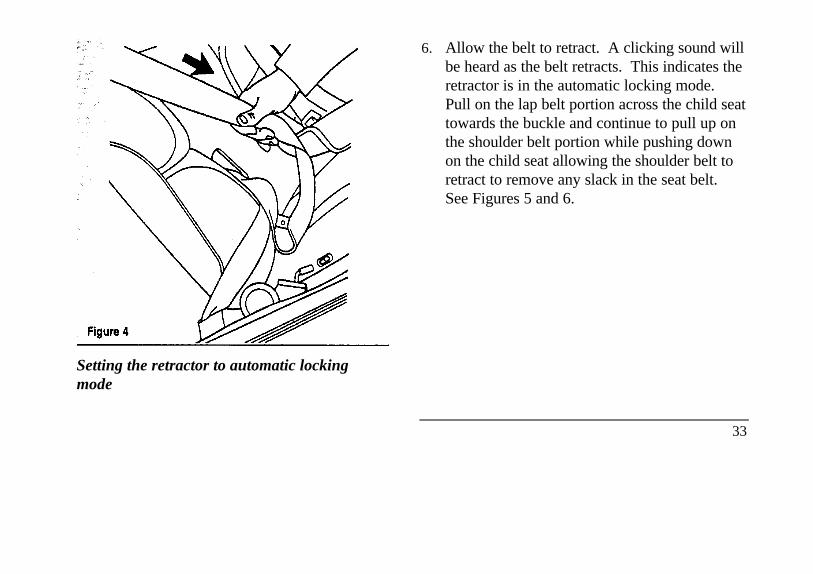
Setting the retractor to automatic lockingmode
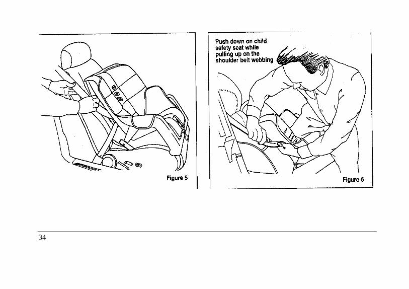
6. Allow the belt to retract. A clicking sound willbe heard as the belt retracts. This indicates theretractor is in the automatic locking mode.Pull on the lap belt portion across the child seattowards the buckle and continue to pull up onthe shoulder belt portion while pushing downon the child seat allowing the shoulder belt toretract to remove any slack in the seat belt.See Figures 5 and 6.
33
34

7. Before placing the child in the child seat,forcibly tilt the seat from side to side and inforward directions to make sure that the seat issecurely held in place. See Figure 7.
Checking that the seat is secure
35
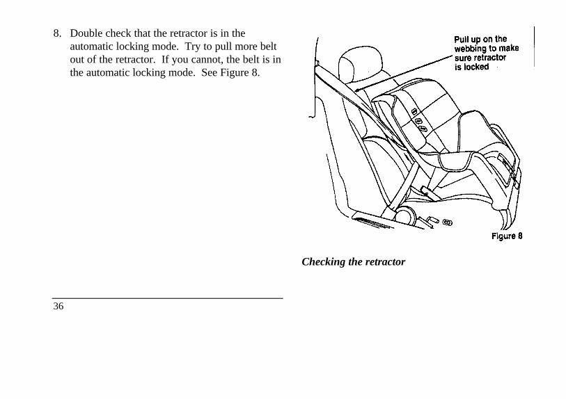
8. Double check that the retractor is in theautomatic locking mode. Try to pull more beltout of the retractor. If you cannot, the belt is inthe automatic locking mode. See Figure 8.
36
Checking the retractor
9. Check to make sure that the child seat isproperly secured prior to each use. If theretractor is not locked, repeat steps 6 through8.
NOTE: To remove the retractor fromautomatic lock mode, allow seat belt to retract fullyto its stowed position and the retractor willautomatically switch back to the vehicle sensitivelocking mode for normal adult usage.
Installing a Child Safety, Seat at theFront Center Seating Position withAdjustable Lap Belt-
1. Lengthen the lap belt. To lengthen the belt,hold the tongue so that its bottom isperpendicular to the direction of webbingwhile sliding the tongue up the webbing.
2. Place the child safety seat in the center seatingposition.
3. Route the tongue and webbing through thechild seat according to the child seatmanufacturer's instructions.
4. Insert the belt tongue into the proper bucklefor the center seating position until you heara snap and feel it latch. Make sure thetongue is m securely fastened to the buckleby pulling on tongue.
5. Push down on the child seat while pulling onthe loose end of the lap belt webbing totighten the belt.
6. Before placing the child into the child seat,forcibly tilt the child seat from side-to-sideand in forward directions to ensure that theseat is held securely in place. If the child seatmoves excessively, repeat steps 5 through 6,or properly install the child seat in a differentseating position.
37
/!\WARNING
Carefully follow all of the manufacturer'sinstructions included with the safety seat youput in your vehicle. If you do not install anduse the safety seat properly, the child may beinjured in a sudden stop or collision.
Attaching Safety Seats With Tether Straps
Some manufacturers make safety seats that includea tether strap that goes over the back of the vehicleseat and attaches to an anchoring point. Othermanufacturers offer the tether strap as anaccessory. Contact the manufacturer of your childsafety seat for information about ordering a tetherstrap.
Tether anchorage hardware
All vehicles include a tether anchor installed at therear center seating position for use with child safetyseats. Attachment holes (at each rear outboard
38
seating position) have been provided in yourvehicle to attach anchor hardware, if required.Additional kits can be obtained at no charge fromany Ford or Lincoln-Mercury dealer.
Safety Belts for Children
Children who are too large for child safety seatsshould always wear safety belts. (See instructionswith your child seat, or contact its manufacturer,to determine maximum size of child that willsafely fit in the seat.)
/!\ WARNING
If safety belts are not properly worn andadjusted as described, the risk of seriousinjury to the child in a collision will bemuch greater.
If the shoulder belt portion of the lap/shoulder beltcan be positioned so that it does not cross or rest infront of the child's face or neck, the child shouldwear the lap/shoulder belt. Moving the child closerto the seat belt buckle may help provide a goodshoulder belt fit.
To improve the fit of lap and shoulder belts onchildren who have outgrown child safety seats,Ford recommends use of a belt-positioning boosterseat that is labelled as conforming to all Federalmotor vehicle safety standards. Belt-positioningbooster seats raise the child and provide a shorter,firmer seating cushion that encourages safer seatingposture and better fit of lap and shoulder belts onthe child. A belt-positioning booster should beused if the shoulder belt rests in front of the child'sface or neck, or if the lap belt does not fit snugly onboth thighs, or if the thighs are too short to let thechild sit all the way back on the seat cushion whenthe lower legs hang over the edge of the seatcushion. You may wish to discuss the specificneeds of your child with your pediatrician.
/!\ WARNING
Do not use a belt-positioning booster witha lap-only belt.
Lap belts and the lap belt portion of lap andshoulder belts should always be worn snugly andbelow the hips, touching the child's thighs.
/!\ WARNING
To reduce the risk of serious injury incollision, children should always ride withthe seatback upright.
39
Starting Your Continental
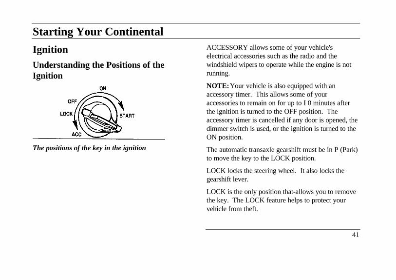
IgnitionUnderstanding the Positions of theIgnition
The positions of the key in the ignition
ACCESSORY allows some of your vehicle'selectrical accessories such as the radio and thewindshield wipers to operate while the engine is notrunning.
NOTE:Your vehicle is also equipped with anaccessory timer. This allows some of youraccessories to remain on for up to I 0 minutes afterthe ignition is turned to the OFF position. Theaccessory timer is cancelled if any door is opened, thedimmer switch is used, or the ignition is turned to theON position.
The automatic transaxle gearshift must be in P (Park)to move the key to the LOCK position.
LOCK locks the steering wheel. It also locks thegearshift lever.
LOCK is the only position that-allows you to removethe key. The LOCK feature helps to protect yourvehicle from theft.
41
OFF allows you to shut off the engine and allaccessories without locking the steering wheel, or thegearshift lever.
ON allows You to test your vehicle's warning lights(except the brake system warning light) to make surethey work before you start the engine. The key returnsto the ON position once the engine is started andremains in this position while the
engine runs.
START cranks the engine. Release the key once theengine starts so that you do not damage the starter. Thekey should return to ON when You release it. TheSTART position also allows You to test the BrakeWarning Light.
42
Removing the Key From the Ignition1. Put the gearshift in P (Park)-
2. Set the parking brake fully.
3. Turn the ignition key to LOCK.
4. Remove the key.
If the key is stuck in the LOCK position, move thesteering wheel left or right until the key turns freely.
If the driver's door is open while the key is still in theignition, a warning chime sounds.
/!\ WARNING
Always set the parking brake fully andmake sure that the gearshift is securelylatched in P (Park).
/!\ WARNING
Do not leave children, unreliable adults,or pets alone in your vehicle. They couldaccidentally injure themselves or othersthrough inadvertent operation of thevehicle. Further, on hot, sunny days,temperatures in a closed vehicle couldquickly become high enough to causesevere and possibly fatal injuries to peopleas well as animals.
Fuel-Injected EnginesWhen starting a fuel-injected engine, the mostimportant thing to remember is to avoid pressingdown on the accelerator before or during starting.Only use the accelerator when you have problemsgetting your vehicle started. See Starting Your Enginein this chapter for details about when to use theaccelerator while you start your vehicle.
Staring Your VehiclePreparing to Start Your Vehicle
/!\WARNING
Do not start your vehicle in a closed garage orother enclosed area. Never sit in a stoppedvehicle for more than a short period of timewith the engine running. Exhaust fumes aretoxic. See Guarding Against Exhaust Fumesin this chapter for more instructions.
Before you start your vehicle, do the following:
1. Make sure you and all your passengers buckleyour safety belts. See Safety Restraints in theIndex for more details.
2. Make sure the headlamps and other accessoriesare turned off when starting.
43
3. Make sure that the gearshift is in P (Park) and theparking brake is set before you turn the key.
Before you start your vehicle, you should test thewarning lights on the instrument panel to make sure thatthey work. Refer to the Warning Lights and Gaugeschapter.
Starting Your EngineTo start your engine:
1. Follow the steps under Preparing to Start YourVehicle at the beginning of this section.
2. Turn the ignition key to the ON position.
3. DO NOT depress the accelerator pedal whenstarting your engine. DO NOT use the acceleratorwhile the vehicle is parked.
44
4. Turn the key to the START position (cranking)until the engine starts. Allow the key to return tothe ON position after the engine has started.
If you have difficulty in turning the key, rotate thesteering wheel slightly because it may be binding.
For a cold engine:
At temperatures 10°°F (-12°°C) and below: If theengine does not start in fifteen (15) seconds on thefirst try, turn the key to OFF, wait approximatelyten (10) seconds so you do not flood the engine,then try again.
At temperatures above 10°°F (-12°°C): If theengine does not start in five (5) seconds on thefirst try, turn the key to OFF, wait approximatelyten (10) seconds so you do not flood the engine,then try again.
For a warm engine:
Do not hold the key in the START position for morethan five (5) seconds at a time. If the engine doesnot start within five (5) seconds on the first try, turnthe key to the OFF position. Wait a few secondsafter the starter stops, then try again.
Whenever you start your vehicle, release the key as soonas the engine starts. Excessive cranking could damagethe starter or flood the engine.
After you start the engine, let it idle for a few seconds.Keep your foot on the brake pedal and put thegearshift lever in gear. Release the parking brake.Slowly release the brake pedal and drive away in thenormal manner.
NOTE:Your vehicle is equipped with an automatictransaxle that has an interlock that prevents you fromshifting out of P (Park) unless your foot is on the brakepedal.
If the engine does not start after twoattempts:
1. Turn the ignition key to the OFF position
2. Press the accelerator all the way to the floorand hold it.
3. Turn the ignition key to the START position,
4. Release the ignition key when the enginestarts
5. Release the accelerator gradually as theengine speeds up. Then drive away in thenormal manner.
If the engine still does not start, the fuel pumpshut-off may have been triggered. For directionson how to reset the switch see Fuel Pump Shut-Off Switch later in this chapter.
45
A computer system controls the engine's idle speed.When you start your vehicle, the engine's idle speednormally runs higher than when it is warmed up. Thesefaster engine speeds will make your vehicle moveslightly faster than its normal idle speed. It should,however, slow down after a short time. If it does not,have the idle speed checked.
If the engine idle speed does not slow downautomatically, do not allow your vehicle to idle for morethan 10 minutes. Have the vehicle checked.
/!\ WARNING
Extended idling at high engine speeds can producevery high temperatures in the engine and exhaustsystem, creating the risk of fire or other damage.
46
/!\ WARNING
Do not park, idle, or drive your vehicle in drygrass or other dry ground cover. Theemission system heats up the enginecompartment and exhaust system, which canstart a fire.
Engine Block Heater (If equipped)Engine block heaters are strongly recommended ifyou live in a region where temperatures reach -10°°F(-23°°C) or below. An engine block heater warmsthe engine coolant, which improves starting, warmsup the engine faster, and allows the heater-defrostsystem to respond quickly.
To turn the heater on, simply plug it into agrounded 110-volt outlet. Ford recommends thatyou use a 110-volt circuit that is protected by aground fault circuit interrupter.
/!\ WARNING
To prevent electrical shock, do not use yourheater with ungrounded electrical systemsor two-pronged (cheater) adapters.
For best results, plug the heater in at least threehours before you start your vehicle. Using theheater for longer than three hours will not damagethe engine, so you can plug it in at night to startyour vehicle the following morning.
If the Engine Cranks but DoesNot Start After a CollisionFuel Pump Shut-off Switch
If the engine cranks but does not start or doesnot start after a collision, the fuel pump shut-offswitch may have been triggered. The shut-offswitch is a device intended to stop the fuel pumpwhen your vehicle has been involved in asubstantial jolt.
Once the shut-off switch is triggered, you mustreset the switch by hand before you can startyour vehicle. The switch is on the left side of thetrunk.
47
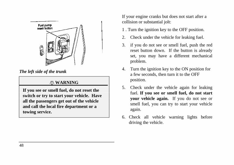
The left side of the trunk
/!\ WARNING
If you see or smell fuel, do not reset theswitch or try to start your vehicle. Haveall the passengers get out of the vehicleand call the local fire department or atowing service.
48
If your engine cranks but does not start after acollision or substantial jolt:
1 . Turn the ignition key to the OFF position.
2. Check under the vehicle for leaking fuel.
3. if you do not see or smell fuel, push the redreset button down. If the button is alreadyset, you may have a different mechanicalproblem.
4. Turn the ignition key to the ON position fora few seconds, then turn it to the OFFposition.
5. Check under the vehicle again for leakingfuel. If you see or smell fuel, do not startyour vehicle again. If you do not see orsmell fuel, you can try to start your vehicleagain.
6. Check all vehicle warning lights beforedriving the vehicle.
Pushing
Vehicles with automatic transaxles cannot bestarted by pushing. Follow the directions under IfYour Vehicle Needs a Jump-Start in the RoadsideEmergencies Chapter.
Guarding Against Exhaust Fumes
Carbon monoxide, although colorless and odorless,is present in exhaust fumes. Take precautions toavoid its dangerous effects.
/!\WARNING
Do not start your vehicle in a closed garageor other enclosed area. Never sit in astopped vehicle for more than a shortperiod of time with the engine running.Exhaust fumes are toxic. See GuardingAgainst Exhaust Fumes in this chapter formore instructions.
/!\WARNINGIf you smell exhaust fumes inside yourvehicle, have your dealer inspect yourvehicle immediately. Do not drive if yousmell exhaust fumes.
49

Have the exhaust and body ventilation systemschecked whenever:
your vehicle is raised for service
the sound of the exhaust system changes
your vehicle has been damaged in a collision
Improve your ventilation by keeping all air inletvents clear of snow, leaves, and other debris.
50
If the engine is idling while you are stopped in anopen area for long periods of time, open thewindows at least one inch (2 . 5 cm). Also,adjust the heating or air conditioning to bring inoutside air.
If you use the Electronic Automatic ClimateControl, set the fan speed selector dial to amedium or high blower speed with the VENT orPNL-FLR function buttons pressed.
Warning Lights and Gauges
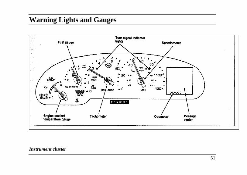
Instrument cluster
51
The following warning lights and gauges are onthe instrument cluster. AD of the warninglights and gauges alert you to possibleproblems with your vehicle.
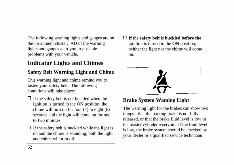
Indicator Lights and ChimesSafety Belt Warning Light and Chime
This warning light and chime remind you tofasten your safety belt. The followingconditions will take place:
If the safety belt is not buckled when theignition is turned to the ON position, thechime will turn on for four (4) to eight (8)seconds and the light will come on for oneto two minutes.
If the safety belt is buckled while the light ison and the chime is sounding, both the lightand chime will turn off.
52
If the safety belt is buckled before theignition is turned to the ON position,neither the light nor the chime will comeon.
Brake System Waming Light
The warning light for the brakes can show twothings - that the parking brake is not fullyreleased, or that the brake fluid level is low inthe master cylinder reservoir. If the fluid levelis low, the brake system should be checked byyour dealer or a qualified service technician.
This light comes on when the parking brake isset, or if it is not set, it comes on briefly whenyou turn the ignition to the START position. Itnormally goes off shortly after the engine startsand you release the parking brake. If the lightstays on after you have fully released theparking brake, have the hydraulic brake systemserviced by your dealer or a qualified servicetechnician.
/!\WARNING
The BRAKE light indicates that the brakesmay not be working properly. Have thebrakes checked immediately.
Anti-Lock Brake System Warning Light
This light comes on for a few seconds when youturn the ignition key to the START position. Itshould go off shortly after the engine starts. If itstays on longer than five (5) seconds, it indicatesthat your anti-lock brake system may not beworking properly. Normal braking is not affectedunless the BRAKE system warning light alsoremains on for longer than six (6) seconds. Youshould have your vehicle serviced immediately byyour dealer or qualified service technician to restorethe benefits of the anti-lock feature. See Anti-lockbrakes in the Index for more information.
53
Engine Oil Pressure Warning Light
This light indicates the engine's oil pressure, notthe oil level. However, if your engine's oil levelis low, it could affect the oil pressure. Thelight will come on briefly when you turn yourkey to the START and ON position. The lightshould stay off when the engine is running withnormal oil pressure. If the light comes on whilethe engine is running, you have lost oil pressureand continued operation will cause severeengine damage.
54
If you lose engine oil pressure:
1. Pull off the road as soon as safely possible.
2. Shut off the engine immediately or severe enginedamage could result.
3. Check the engine's oil level, following theinstructions on checking and adding engine oil,see the Engine Oil in the Index. If you do notfollow these instructions, you or others could beinjured. To assure an accurate reading, your carshould be on level ground.
4. If the level is low, add only as much oil asnecessary before you start the engine again. Donot overfill. Do not operate the engine if the lightis on, regardless of the oil level. Contact yournearest dealer for further service actions.
For more information about adding oil, see Addingengine oil in the Servicing Your Vehicle chapter.
Traction Control Active Light (Ifequipped)
This light comes on when the TractionContron system begins applying and releasingthe brakes and adjusting the enginecharacteristics to limit a wheelspin condition.
It will be lit for a minimum of six seconds orfor the duration of the Traction Controlevent.
T/C
ACTIVE
Charging System Light
This light indicates that your battery is not beingcharged and that you need to have the electricalsystem begins applying and releasing the brakesand system checked.
55
This light comes on every time you turn theignition to the ON or START position (engineoffl. The light should go off when the enginestarts and the alternator begins to charge.
If the light stays on or comes on when theengine is running, have the electrical systemchecked as soon as possible.
Turn Signal Indicator Lights
When you push the turn signal lever up beforemaking a right turn, the right side arrow on theinstrument panel flashes.
When you push the turn signal lever downbefore making a left turn, the left side arrow onthe instrument panel flashes.
Usually, the turn signals turn off automaticallyafter you turn your car. If the turn signalcontinues to flash after you have made the turn,push the lever back to the OFF position.
56
If one or both of your turn indicators do not flashor stay on continuously, have them serviced assoon as possible. In the meantime, be sure to usethe accepted hand signals.
Service Engine Soon Warning Light
The Powertrain On-Board Diagnostic 11(OBD 11) system consists of the hardwareand software necessary to monitor theoperation of the powertrain. The OBD 11system is designed to check the functionof the vehicle's powertrain control systemduring normal operation. If an emissionproblem is detected, the Service EngineSoon light (in the cluster) is turned on.
Modification or additions to the vehicle maycause incorrect operation of the OBD 11system. Additions such as burglar alarms,cellular phones, and CB radios must becarefully installed. Do not install thesedevices by tapping into or running wires closeto powertrain control system wires orcomponents.
SERVICEENGINESOON
The light comes on briefly when you turn the ignitionto the ON position, but should turn off when theengine starts. If the light does not come on when youturn the ignition to the ON position or if it comes onand stays on when you are driving, have your vehicleserviced as soon as conveniently possible.
This indicates a possible problem with one of thevehicle's emission control systems. You do notneed to have your vehicle towed in.
If the light turns on and off at one second intervalswhile you are driving the vehicle, it means that theengine is misfiring. If this condition persists,damage could occur to the engine or catalyticconvertor. Have your vehicle serviced at the firstopportunity.
If the light turns on and off on rare occasionswhile you are driving, it means that a malfunctionoccurred and the condition corrected itself.
An example of a condition which corrects itselfoccurs when an engine running out of fuel beginsto misfire. In this case, the Service Engine SoonLight may turn on and will then set a diagnostictrouble code indicating that the engine wasmisfiring while the last of the fuel was beingconsumed. After refueling, the Service EngineSoon Light wfll turn off after the vehicle hascompleted three consecutive warm up cycleswithout a misfire
57
condition occurring. A warm up cycle consistsof engine start from a cold condition (engine atambient temperature) and running until theengine reaches normal operating temperature.
On the fourth engine start up, the ServiceEngine Soon light will turn off as soon as theengine begins to crank. It is not necessary tohave the engine serviced.
Under certain conditions, the Service EngineSoon Light may come on if the fuel cap is notproperly installed. If the Service Engine SoonLight comes on and you suspect that the fuelcap is not properly installed, pull off the road assoon as it is safely possible and turn off theengine. Remove and replace the cap, makingsure it is properly seated.
After completing the three consecutive warmup cycles and on the fourth engine start up, theService Engine Soon Warning Light shouldturn off. If the light does not go off after thefourth engine re-start, have your vehicleserviced by your dealer or a qualifiedtechnician.
58
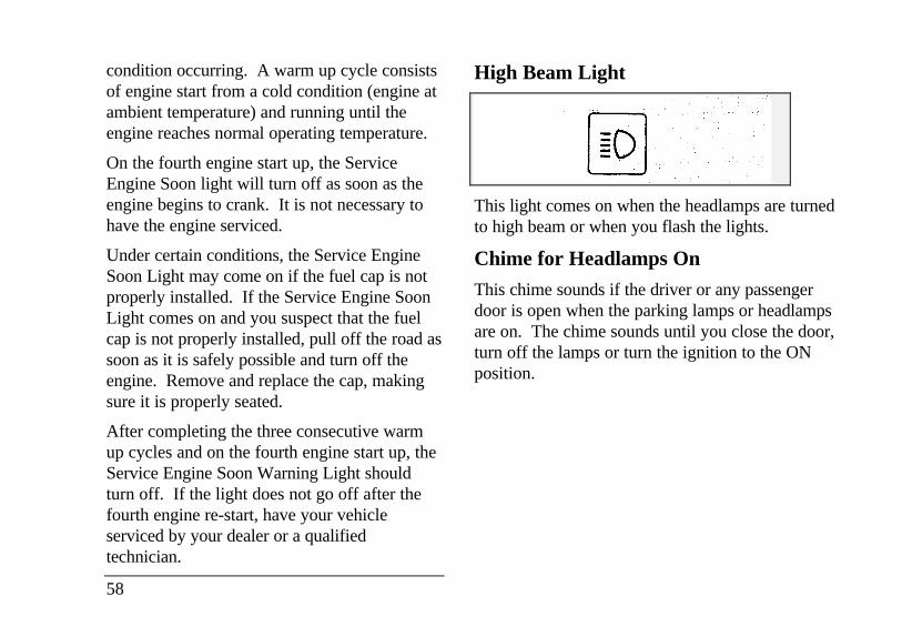
High Beam Light
This light comes on when the headlamps are turnedto high beam or when you flash the lights.
Chime for Headlamps On
This chime sounds if the driver or any passengerdoor is open when the parking lamps or headlampsare on. The chime sounds until you close the door,turn off the lamps or turn the ignition to the ONposition.
Air Bag Readiness Light
The air bag system uses a readiness light anda tone to indicate the condition of the system.The readiness light is in the instrumentcluster. When you turn the ignition key to theON position, this light will light up for six (6)seconds and then turn off. This indicates thatthe system is operating normally. NOTE:Regularly scheduled maintenance of the airbag system is not required.
AIR
BAG
If the light fails to Ruminate, continues toflash, remains on, or you hear a beepingsound, have the system serviced at your Fordor Lincoln-Mercury dealer immediately.
Anti-Theft Alarm Light(If equipped)
This light flashes on and off when the ignition isturned to the OFF position and any door isopened. As soon as you lock the doors, the lightglows steadily. Within 30 seconds of closing allthe doors, the light goes out. This indicates thatthe alarm system is armed.
ANTI-
THEFT
See Anti-Theft System in the Features chapter formore information.
59
The Instrument ClusterIn addition to warning lights, the instrumentcluster has a message center/odometer, aspeedometer, tachometer, fuel and coolanttemperature gauges.
The Electronic Message Center (M/C)
The Electronic Message Center only workswhen the ignition is in the ON position.
Each time the WC is powered the display goesthrough a self test by displaying the PLEASEFASTEN SEATBELT message. This self testis used to stabilize the systems before reportingthe status to you.
60
The message center tells you about thecondition of your vehicle by two methods:
operator selectable features
continuous warning reporting ofmonitored systems
You can select different features for the M/C todisplay by using the message center controlbuttons located to the right of the instrumentcluster. You will hear a tone when you press oneof these buttons. However, if the M/C detects awarning from any of the monitored systems, thenthe M/C will display the appropriate warningmessage.
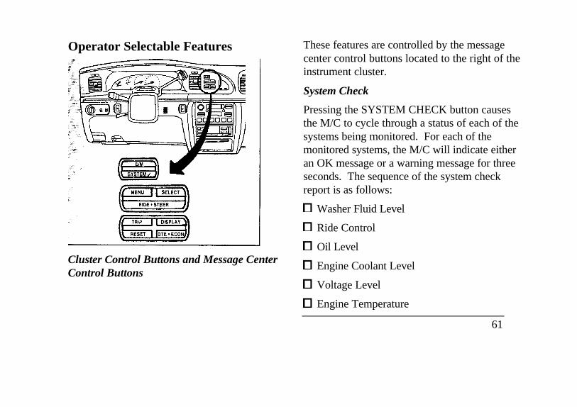
Operator Selectable Features
Cluster Control Buttons and Message CenterControl Buttons
These features are controlled by the messagecenter control buttons located to the right of theinstrument cluster.
System Check
Pressing the SYSTEM CHECK button causesthe M/C to cycle through a status of each of thesystems being monitored. For each of themonitored systems, the M/C will indicate eitheran OK message or a warning message for threeseconds. The sequence of the system checkreport is as follows:
Washer Fluid Level
Ride Control
Oil Level
Engine Coolant Level
Voltage Level
Engine Temperature
61
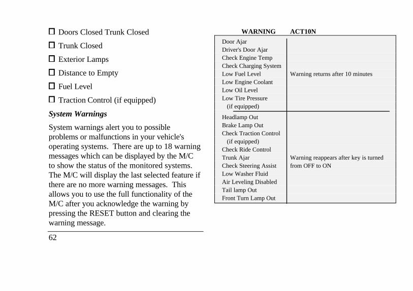
Doors Closed Trunk Closed
Trunk Closed
Exterior Lamps
Distance to Empty
Fuel Level
Traction Control (if equipped)
System Warnings
System warnings alert you to possibleproblems or malfunctions in your vehicle'soperating systems. There are up to 18 warningmessages which can be displayed by the M/Cto show the status of the monitored systems.The M/C will display the last selected feature ifthere are no more warning messages. Thisallows you to use the full functionality of theM/C after you acknowledge the warning bypressing the RESET button and clearing thewarning message.
62
WARNING ACT10N
Door AjarDriver's Door AjarCheck Engine TempCheck Charging SystemLow Fuel Level Warning returns after 10 minutesLow Engine CoolantLow Oil LevelLow Tire Pressure
(if equipped)
Headlamp OutBrake Lamp OutCheck Traction Control
(if equipped)Check Ride ControlTrunk Ajar Warning reappears after key is turnedCheck Steering Assist from OFF to ONLow Washer FluidAir Leveling DisabledTail lamp OutFront Turn Lamp Out

Warning messages that have been reset aredivided into two categories. They willreappear on the display ten minutes from thereset or they will not reappear until an ignitionOFF-ON cycle has been completed. Thisreappearing of warning messages is a reminderthat these warning conditions still exist withinthe vehicle.
EIM
A press of this button allows you to change theM/C and the Electronic Climate control unitfrom English to Metric Units. When you pressthis button all displays change from English toMetric or Metric to English units. Thedisplays remain in the units you have chosenuntil you change them again even after youturn off the vehicle and start it again.
TRIP
Pressing this button will display the first of twotrip odometers. Pressing it again will displaythe second Trip Odometer. Pressing RESETwill clear only that Trip odometer which isdisplayed.
DTE/ECON
Pressing this button a first time will displayapproximately how many miles you can drive beforeyou run out of fuel, or in other words the DistanceTo Empty (DTE). To ensure accuracy, turn theignition OFF when you fill the tank.
Pressing this button a second time will allow you todisplay your Average Fuel Economy in miles/gallonor Uters/100 kilometers. Your WC computes thisfigure using the distance traveled and rate of fuelused information. If you want to reset this feature,press the RESET button while the Average FuelEconomy feature is displayed.
NOTE: DTE (Distance to Empty) is calculatedusing a "Running Average Fuel Economy" initializedby the factory. This value is not the same as theAverage Fuel Economy Display. The RunningAverage Economy is based on more than 500 miles(800 km) of driving history. Also the factory defaultfor Running Average Economy is reinitialized if thebattery is disconnected.
63
If the FUEL LEVEL ERROR message isdisplayed this means that there is a problemwith the fuel indication system and you shouldcontact your dealer for service as soon aspossible.
RESET
A press of the RESET button will allow you toreset the current feature displayed. Warnings,Average Fuel Economy, and Trip odometersare the only features which respond to theRESET button. Distance to Empty (DTE),RIDE/STEER and MENU are unaffected bypressing the RESET switch.
DISPLAY
Pressing this button will cause the messagecenter display to turn off. Pressing it again willcause the display to come on again. Warningsoverride an off display and must be reset inorder for the display to be off again.
64
RIDE/STEER
Pressing this button once will allow you toadjust your RIDE CONTROL settings, betweenNORMAL, PLUSH and FIRM. The settings arechanged by pressing the SELECT button whileRIDE CONTROL is displayed.
Pressing the RIDE/STEER button a second timewill allow you to adjust the STEERINGEFFORT settings between NORMAL, LOW,and HIGH. The settings are changed bypressing the SELECT button while STEERINGEFFORT is displayed.
NOTE: The combination of FIRM RIDECONTROL and LOW STEERING EFFORT isundesirable and cannot be selected.
MENU
Pressing this button will allow You to changevarious convenience settings throughout thevehicle. The settings for each feature arechanged by pressing the SELECT button-
Pressing the MENU button once will allow youto enable or disable the EXPRESS WINDOWfeature. This feature allows one tap downoperation on the driver's window using thewindow switch on the driver's door armrest.
Pressing MENU again will allow you to enableor disable the AUTO DOOR LOCK feature.This feature automatically locks all doors whenthe driver shifts out of PARK, all doors areclosed, the driver's seat is occupied, and thevehicle is traveling over three mph (5 km/h).
Pressing MENU again will allow you toenable or disable the HORN CHIRP feature.When HORN CHIRP is ON the horn willbriefly sound when the Remote Entry KeyFob LOCK button is pressed. This verifiesthe doors have been locked and the ANTI-THEFT system has been armed (if equipped).
Pressing MENU again will allow you toenable or disable the SEAT ACCESS feature.When ON, the driver's seat will move back 2inches (5 cm) or to
end of seat track travel when the vehicle isturned off and the ignition key is removed.Upon the driver entering the vehicle andclosing the door, the seat will moveforward to its previous position.
Pressing MENU again will allow you to enable ordisable the REVERSE MIRRORS feature. WhenON, the outside rearview mirrors tilt down whenthe gearshift is placed in R (Reverse). Thisprovides for an improved view of the side of thevehicle and curb area when backing up. Whenyou shift out of REVERSE the mirrors return totheir previous positions.
Odometer
The odometer tells you the total number of miles(kilometers) your vehicle has been driven.
If the odometer displays the word Error, pleasecontact your dealer for service.
65
Speedometer
The speedometer tells you how many miles(kilometers) per hour your vehicle is moving.
Tachometer
The tachometer displays the approximateengine revolutions per minute (rpm), or howfast the engine is running.
You can drive your vehicle at most rpm pointson the tachometer but you must stay out of thered zone.
If you drive with the tachometer in the redzone, you may damage the engine.
Engine Coolant Temperature Gauge
This gauge indicates the temperature of theengine coolant, not the coolant level. If thecoolant is not at its proper level or mixture, thegauge indication will not be accurate.
66
The pointer moves from the C (cold) mark into theNORMAL band as the engine coolant warms up. Itis acceptable for the pointer to fluctuate within theNORMAL band under normal driving conditions.Under certain driving conditions such as, heavy stopand go traffic, or driving up hills in hot weather, thepointer may indicate at the top of the NORMALband.
If, under any circumstances, the pointer moves abovethe NORMAL band, the engine coolant isoverheating and continued operation may causeengine damage.
If your engine coolant overheats:
1. Pull off the road as soon as it is safely possible.
2. Turn off the engine.
3. Let the engine cool. DO NOT REMOVECOOLANT SYSTEM FILL CAP UNTILTHE ENGINE IS COOL.
4. Check the coolant level following theinstructions on checking and adding coolantto your engine, see the Engine Coolant inthe Index. If you do not follow theseinstructions, you or others could be injured.
If the coolant continues to overheat, have the
coolant system serviced as soon as possible.
Fuel Gauge
The fuel gauge displays approximately howmuch fuel you have in the fuel tank. Theignition switch must be in the OFF positionwhile filling the tank with at least three gallons(I I liters) for the fuel gauge to indicate thenew level. If the ignition is left ON or less than3 gallons (I 1 liters) of fuel are added the fuelgauge will not immediately indicate the newfuel level. The gauge will gradually correctitself to indicate the true fuel level.
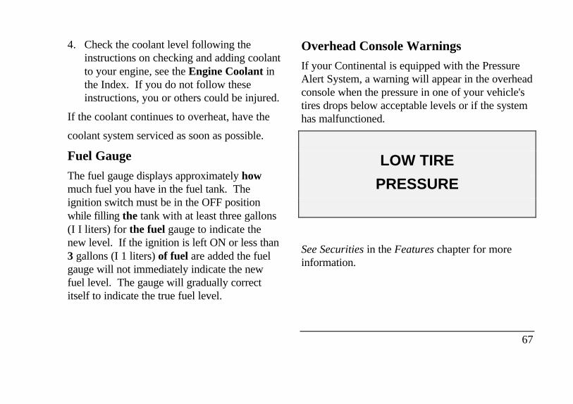
Overhead Console Warnings
If your Continental is equipped with the PressureAlert System, a warning will appear in the overheadconsole when the pressure in one of your vehicle'stires drops below acceptable levels or if the systemhas malfunctioned.
LOW TIRE
PRESSURE
See Securities in the Features chapter for moreinformation.
67
Lincoln RESCU System(If equipped)Lincoln RESCU runs a self-test when you startyour vehicle. During this test, the Lincoln RESCUwarning light, located in the overhead console, willbriefly illuminate. If a problem is detected duringthe self-check, the light will remain lit and themessage "RESCU FAILURE" will be displayed onthe vehicle's message center for several seconds.
If the warning light fails to briefly illuminatewhen you start your vehicle or if it remainslit, have your Lincoln RESCU Systemchecked by an authorized Lincoln/Mercurydealer as soon as possible. Your system maybe inoperative.
68
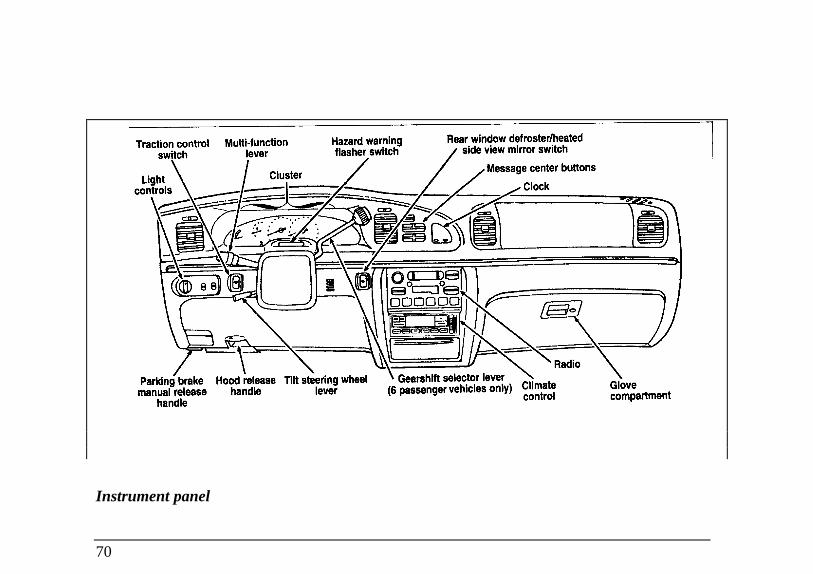
Instrument Panel ControlsThe instrument panel (dashboard) on yourvehicle is divided into several differentsections. The illustrations on the followingpages show the major parts of theinstrument panel that are described in thischapter. Some items shown may not be onall vehicles.
The main controls for the climate control system,clock, and radio are on the instrument panel.
If you have radio transmitting equipment in yourvehicle, be aware that it can interfere with yourvehicle's electrical system and may cause theinstrumentation and/or convenience products tohave temporary, abnormal operation.
NOTE: Any cleaner or polish that increases thegloss (shine) of the upper part of the instrumentpanel should be avoided. The dull finish in thisarea is to help protect the driver from undesirablewindshield reflection.
Clean the instrument panel lens and woodtone trimwith a soft cloth and a glass cleaner. Do not usepaper towel or any abrasive cleaner to clean eitherthe lens or the woodtone trim as these may causescratches.
69
Light
Instrument panel
70
Cluster Hood release handleRear window def roster/heated
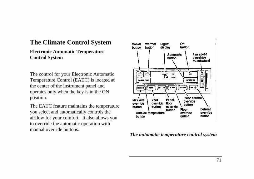
The Climate Control SystemElectronic Automatic TemperatureControl System
The control for your Electronic AutomaticTemperature Control (EATC) is located atthe center of the instrument panel andoperates only when the key is in the ONposition.
The EATC feature maintains the temperatureyou select and automatically controls theairflow for your comfort. It also allows youto override the automatic operation withmanual override buttons.
The automatic temperature control system
71
To turn your EATC on, push the AUTOMATICbutton or any of the six override buttons alongthe bottom of the control.
To turn your EATC off, press the OFF button.When the system is off, the display window willbe blank (dark) except when OUTSIDE TEMPhas been selected. Then, OUTSIDE TEMP andthe temperature will appear in the window.
If you select AUTOMATIC, the system willautomatically determine fan speed and airflowlocation. If an override button is selected, yourselection determines airflow location only. Fanspeed remains automatic unless you override itby rotating the vertical thumbwheel located atthe extreme right of the control panel.
To change the temperature in the displaywindow, select any temperature between 65°F (I8°C) and 85°F (29°C) using the BLUE (cooler)or RED (warmer) buttons. The ElectronicAutomatic Temperature Control will do the rest.
72
If you want continuous maximum cooling, push theBLUE button until 60°F (16°C) is shown in thedisplay window. Your EATC will cool atmaximum and disregard the 60°F (16°C) settinguntil you select a warmer temperature with theRED button. If you want continuous maximumheating, push the RED button until 90°F (32°C) isshown in the display window. Your EATC wiflprovide maximum heat regardless of the 90°F(32°C) setting until you select a cooler temperaturewith the BLUE button.
The display window tells you how the system isoperating. It will indicate the selected temperatureand the operating function you have chosen; AUTOor one of the six manual overrides. It will alsoindicate manual (thumbwheel) control of the fan
speed with the symbol. The display windowwith all possible displays and their positions areshown here. Normally not aU are shown at thesame time but are included here to familiarize youwith the names and symbols.
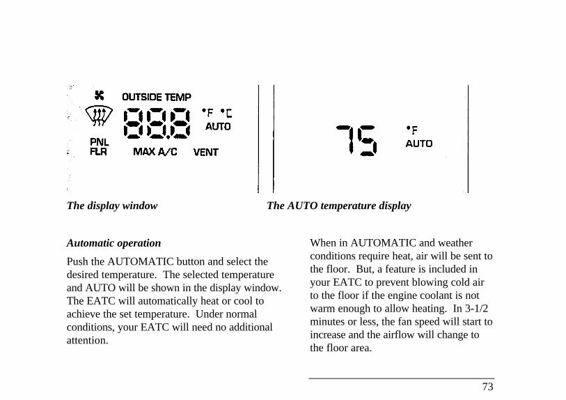
The display window The AUTO temperature display
Automatic operation
Push the AUTOMATIC button and select thedesired temperature. The selected temperatureand AUTO will be shown in the display window.The EATC will automatically heat or cool toachieve the set temperature. Under normalconditions, your EATC will need no additionalattention.
When in AUTOMATIC and weatherconditions require heat, air will be sent tothe floor. But, a feature is included inyour EATC to prevent blowing cold airto the floor if the engine coolant is notwarm enough to allow heating. In 3-1/2minutes or less, the fan speed will start toincrease and the airflow will change tothe floor area.
73
If unusual conditions exist (i.e., window fogging,etc.), the six manual override buttons allowYOU to select special air discharge locations. Athumbwheel allows you to adjust the fan speedto suit your needs.
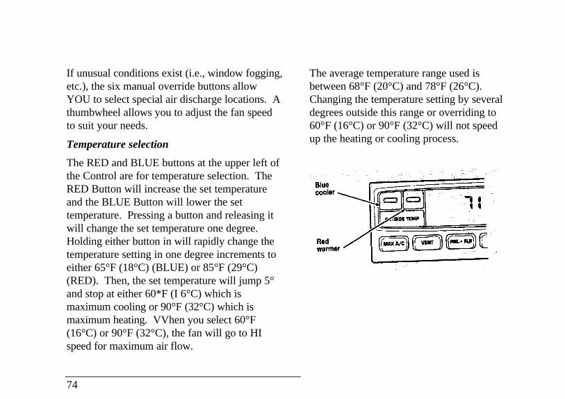
Temperature selection
The RED and BLUE buttons at the upper left ofthe Control are for temperature selection. TheRED Button will increase the set temperatureand the BLUE Button will lower the settemperature. Pressing a button and releasing itwill change the set temperature one degree.Holding either button in will rapidly change thetemperature setting in one degree increments toeither 65°F (18°C) (BLUE) or 85°F (29°C)(RED). Then, the set temperature will jump 5°and stop at either 60*F (I 6°C) which ismaximum cooling or 90°F (32°C) which ismaximum heating. VVhen you select 60°F(16°C) or 90°F (32°C), the fan will go to HIspeed for maximum air flow.
74
The average temperature range used isbetween 68°F (20°C) and 78°F (26°C).Changing the temperature setting by severaldegrees outside this range or overriding to60°F (16°C) or 90°F (32°C) will not speedup the heating or cooling process.
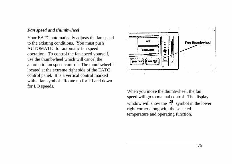
Fan speed and thumbwheel
Your EATC automatically adjusts the fan speedto the existing conditions. You must pushAUTOMATIC for automatic fan speedoperation. To control the fan speed yourself,use the thumbwheel which will cancel theautomatic fan speed control. The thumbwheel islocated at the extreme right side of the EATCcontrol panel. It is a vertical control markedwith a fan symbol. Rotate up for HI and downfor LO speeds.
Fan thumbwheel
When you move the thumbwheel, the fanspeed will go to manual control. The display
window will show the symbol in the lowerright corner along with the selectedtemperature and operating function.
75
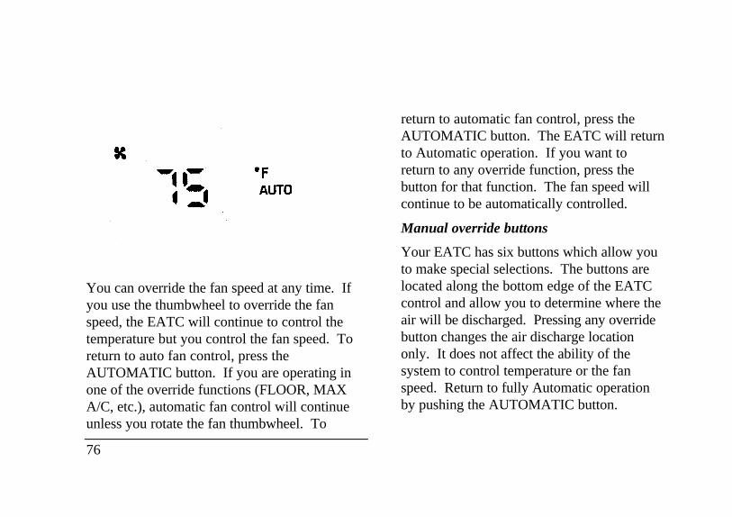
You can override the fan speed at any time. Ifyou use the thumbwheel to override the fanspeed, the EATC will continue to control thetemperature but you control the fan speed. Toreturn to auto fan control, press theAUTOMATIC button. If you are operating inone of the override functions (FLOOR, MAXA/C, etc.), automatic fan control will continueunless you rotate the fan thumbwheel. To
76
return to automatic fan control, press theAUTOMATIC button. The EATC will returnto Automatic operation. If you want toreturn to any override function, press thebutton for that function. The fan speed willcontinue to be automatically controlled.
Manual override buttons
Your EATC has six buttons which allow youto make special selections. The buttons arelocated along the bottom edge of the EATCcontrol and allow you to determine where theair will be discharged. Pressing any overridebutton changes the air discharge locationonly. It does not affect the ability of thesystem to control temperature or the fanspeed. Return to fully Automatic operationby pushing the AUTOMATIC button.
MAX A/C button
The MAX A/C feature allows for faster coolingbecause air is drawn from inside the vehicle.Using inside air causes the fan to sound louderwhich is normal for this selection. The Displaywindow will change to indicate 60°F (16°C) andMAX A/C. The fan will run at high speed andthe airflow will be from the instrument panelregisters. To exit and return to the previoustemperature, push AUTOMATIC or any of theother five override buttons.
VENT button
Push this button to select outside air through theinstrument panel registers. The display windowwill show the set temperature and VENT to thelower right of the temperature. Your EATC willheat the air if the temperature you have selectedis warmer than the outside air coming into thevehicle. However, the air will NOT be cooledregardless of the temperature setting.
PNL & FLR button
Push this button to get air from the floor andinstrument panel registers at the same time.The display will show the set temperature andthe words PNL and FLR. Depending on theselected temperature, the air will beautomatically heated or cooled.
FLOOR button
Airflow will be to the floor when the FLOORbutton is pressed. The display window willshow the set temperature and FLR to the left ofthe temperature. The air cannot be cooled inthe FLOOR position, only heated. Fan speedwill be automatic unless manually controlled. Ifyou override the fan speed and wish to return toautomatic fan control, push AUTOMATIC.Then, again select FLOOR for airflow to thefloor.
77
FLR & DEF button
Push this button to get air to the floor andwindshield defrosters at the same time. Thedisplay will show the set temperature, FLR andthe Defrost symbol. If the outside temperatureis about 50°F (10°C) and above, the air will bedehumidified to remove moisture. This will helpto prevent fogging in humid weather.
DEFROST button
Press the Defrost Button to obtain maximumairflow to the windshield. Adjust thetemperature setting as required for defrosting.The Display window will show the temperaturesetting with the Defrost symbol to the left of thetemperature. When the outside temperature isabout 50°F (10°C) and above, the air will bedehumidified to remove moisture. This will helpprevent fogging in humid weather.
78
OUTSIDE TEMP button
By pressing this button the temperatureof the air outside of the vehicle will showin the display. The outside temperaturewill continue to be displayed until theOUTSIDE TEMP button is pressedagain to cancel. If the selectedtemperature setting is changed while theoutside temperature is displayed, the newselected temperature will be displayed for4 seconds after it is changed. Then, theoutside temperature will return to thewindow. If a manual override is pressedor the thumbwheel is rotated while theoutside temperature is displayed, thewindow will show the change for 4seconds. Then, the outside temperaturewill return along with the changedoverride selection.
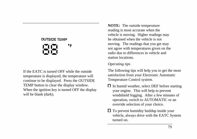
If the EATC is turned OFF while the outsidetemperature is displayed, the temperature willcontinue to be displayed. Press the OUTSIDETEMP button to clear the display window.When the ignition key is turned OFF the displaywill be blank (dark).
NOTE: The outside temperaturereading is most accurate when thevehicle is moving. Higher readings maybe obtained when the vehicle is notmoving. The readings that you get maynot agree with temperatures given on theradio due to differences in vehicle andstation locations.
Operating tips
The following tips will help you to get the mostsatisfaction from your Electronic AutomaticTemperature Control system.
In humid weather, select DEF before startingyour engine. This will help to preventwindshield fogging. After a few minutes ofoperation, switch to AUTOMATIC or anoverride selection of your choice.
To prevent humidity buildup inside yourvehicle, always drive with the EATC Systemturned on.
79
Do not put objects under the front seats thatinterfere with the flow of air to the back seatarea.
Remove any snow, ice, or leaves from the airintake area of your EATC System whichcould block the air intake. The intake area islocated at the bottom of the windshield, underthe hood at the passenger side rear corner.
Service
If your EATC is not operating as described here,take it to your dealer to have it checked. Systemdiagnostics are built in which will allow yourdealer to readily identify problems that mightoccur.
80
Rear Window Defroster andHeated Sideview MirrorsThe rear window and heated outside mirrorsdefroster switch activates the defroster for therear window to clear frost, fog, or thin ice fromboth the inside and outside of the rear windowand activates the heated outside rearviewmirrors.
The button for the rear window and heatedoutside mirrors defroster is on the instrumentpanel to the right of the steering column.
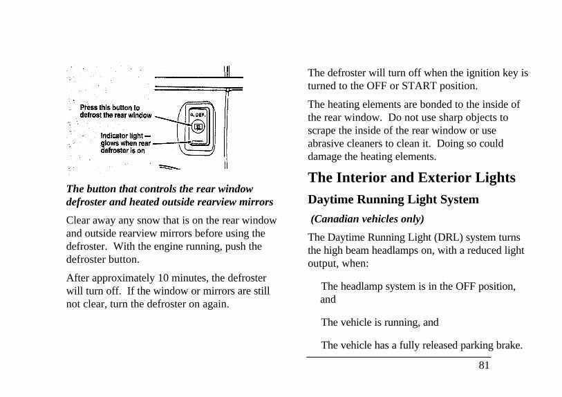
The button that controls the rear windowdefroster and heated outside rearview mirrors
Clear away any snow that is on the rear windowand outside rearview mirrors before using thedefroster. With the engine running, push thedefroster button.
After approximately 10 minutes, the defrosterwill turn off. If the window or mirrors are stillnot clear, turn the defroster on again.
The defroster will turn off when the ignition key isturned to the OFF or START position.
The heating elements are bonded to the inside ofthe rear window. Do not use sharp objects toscrape the inside of the rear window or useabrasive cleaners to clean it. Doing so coulddamage the heating elements.
The Interior and Exterior LightsDaytime Running Light System
(Canadian vehicles only)
The Daytime Running Light (DRL) system turnsthe high beam headlamps on, with a reduced lightoutput, when:
� The headlamp system is in the OFF position,and
� The vehicle is running, and
� The vehicle has a fully released parking brake.
81
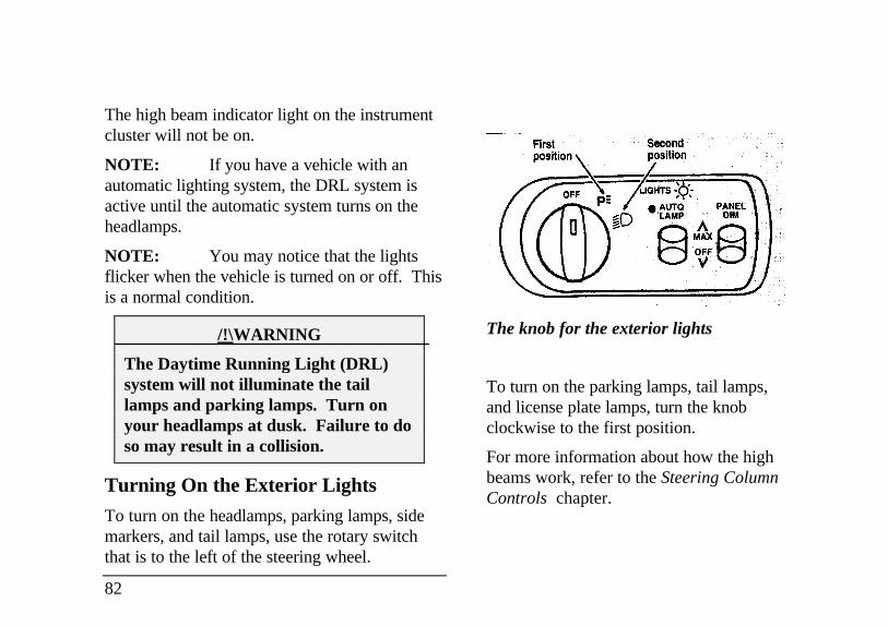
The high beam indicator light on the instrumentcluster will not be on.
NOTE: If you have a vehicle with anautomatic lighting system, the DRL system isactive until the automatic system turns on theheadlamps.
NOTE: You may notice that the lightsflicker when the vehicle is turned on or off. Thisis a normal condition.
/!\WARNING
The Daytime Running Light (DRL)system will not illuminate the taillamps and parking lamps. Turn onyour headlamps at dusk. Failure to doso may result in a collision.
Turning On the Exterior Lights
To turn on the headlamps, parking lamps, sidemarkers, and tail lamps, use the rotary switchthat is to the left of the steering wheel.
82
The knob for the exterior lights
To turn on the parking lamps, tail lamps,and license plate lamps, turn the knobclockwise to the first position.
For more information about how the highbeams work, refer to the Steering ColumnControls chapter.
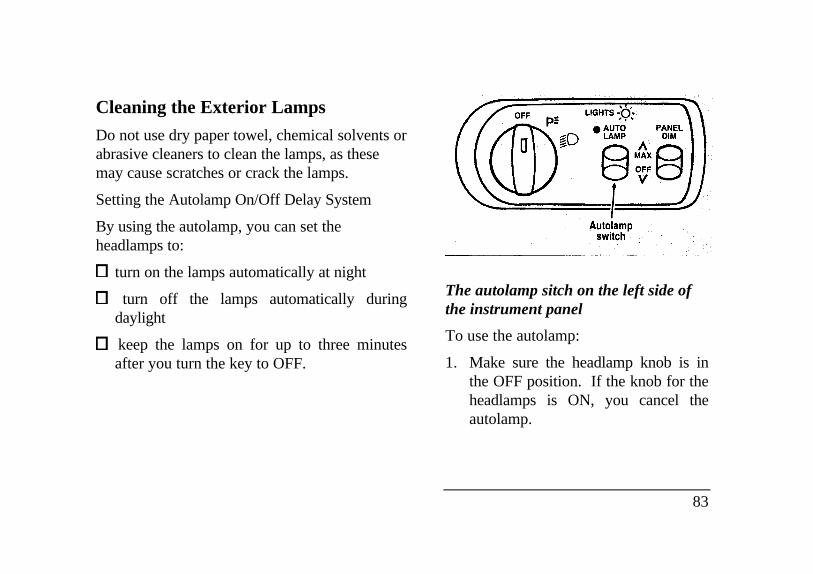
Cleaning the Exterior Lamps
Do not use dry paper towel, chemical solvents orabrasive cleaners to clean the lamps, as thesemay cause scratches or crack the lamps.
Setting the Autolamp On/Off Delay System
By using the autolamp, you can set theheadlamps to:
turn on the lamps automatically at night
turn off the lamps automatically duringdaylight
keep the lamps on for up to three minutesafter you turn the key to OFF.
Autolamp switch
The autolamp sitch on the left side ofthe instrument panel
To use the autolamp:
1. Make sure the headlamp knob is inthe OFF position. If the knob for theheadlamps is ON, you cancel theautolamp.
83
If the autolamp is active, the headlamp systemwill come on immediately after starting yourvehicle. If your vehicle is running before youactivate the autolamp, there may be a 15 seconddelay before the headlights illuminate.
2. Turn the ignition key to ON or start yourvehicle.
3. Find the autolamp switch to the left of thesteering wheel on the instrument panel.
4. Push the autolamp switch up toward theMAX position. As you press this switch, theautolamp system's status will be displayed inthe message center. The system can beturned OFF or can be set to provide light forup to three (3) minutes after you turn yourvehicle off.
84
Do not put any articles on top of the photocellthat is located in the top left corner of theinstrument panel. This photocell controls theautolamp. If you cover it, the photocell reactsas if it is nighttime, and the lamps turn on.
To turn the autolamp off, push the switch downuntil the message center display reaches OFF.
Turning On InteriorLights/Instrument Panel Illumination
You can brighten or dim the lights in theinstrument panel and the compass displayin the inside rearview mirror (ifequipped) with the PANEL DIM switchlocated on the instrument panel.
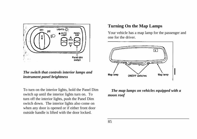
Panel dim switch
The switch that controls interior lamps andinstrument panel brightness
To turn on the interior lights, hold the Panel Dimswitch up until the interior lights turn on. Toturn off the interior lights, push the Panel Dimswitch down. The interior lights also come onwhen any door is opened or if either front dooroutside handle is lifted with the door locked.
Turning On the Map Lamps
Your vehicle has a map lamp for the passenger andone for the driver.
TTThe map lamps on vehicles equipped with amoon roof
85
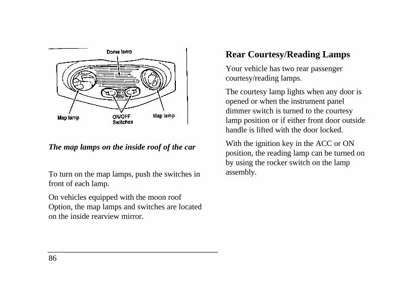
Map lamp Dome lamp ON/OFF Switches
The map lamps on the inside roof of the car
To turn on the map lamps, push the switches infront of each lamp.
On vehicles equipped with the moon roofOption, the map lamps and switches are locatedon the inside rearview mirror.
86
Rear Courtesy/Reading Lamps
Your vehicle has two rear passengercourtesy/reading lamps.
The courtesy lamp lights when any door isopened or when the instrument paneldimmer switch is turned to the courtesylamp position or if either front door outsidehandle is lifted with the door locked.
With the ignition key in the ACC or ONposition, the reading lamp can be turned onby using the rocker switch on the lampassembly.
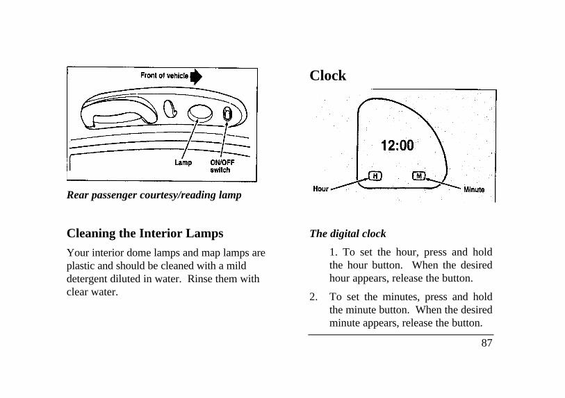
Rear passenger courtesy/reading lamp
Cleaning the Interior Lamps
Your interior dome lamps and map lamps areplastic and should be cleaned with a milddetergent diluted in water. Rinse them withclear water.
Clock
The digital clock
1. To set the hour, press and holdthe hour button. When the desiredhour appears, release the button.
2. To set the minutes, press and holdthe minute button. When the desiredminute appears, release the button.
87
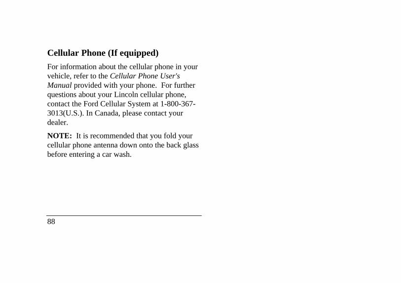
Cellular Phone (If equipped)
For information about the cellular phone in yourvehicle, refer to the Cellular Phone User'sManual provided with your phone. For furtherquestions about your Lincoln cellular phone,contact the Ford Cellular System at 1-800-367-3013(U.S.). In Canada, please contact yourdealer.
NOTE: It is recommended that you fold yourcellular phone antenna down onto the back glassbefore entering a car wash.
88
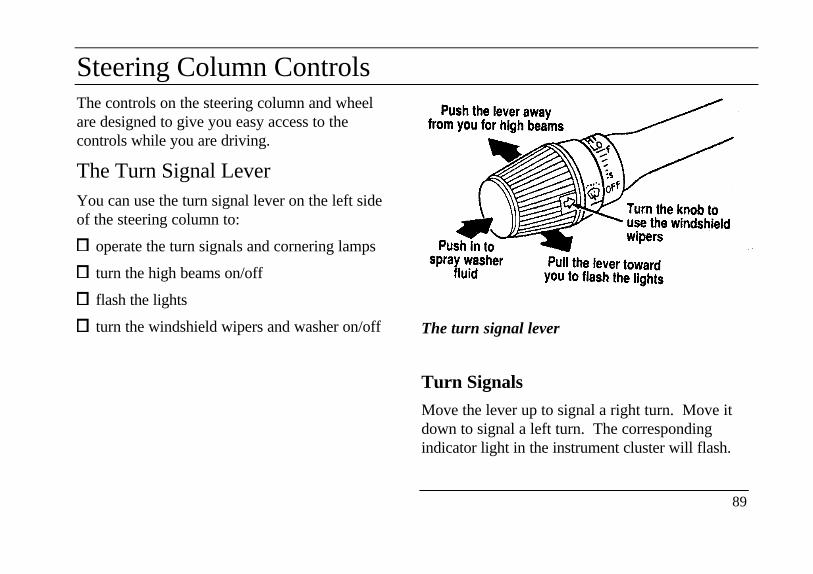
Steering Column ControlsThe controls on the steering column and wheelare designed to give you easy access to thecontrols while you are driving.
The Turn Signal LeverYou can use the turn signal lever on the left sideof the steering column to:
operate the turn signals and cornering lamps
turn the high beams on/off
flash the lights
turn the windshield wipers and washer on/off The turn signal lever
Turn Signals
Move the lever up to signal a right turn. Move itdown to signal a left turn. The correspondingindicator light in the instrument cluster will flash.
89
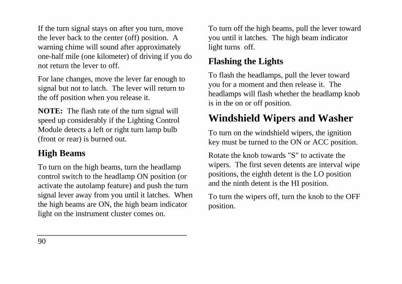
If the turn signal stays on after you turn, movethe lever back to the center (off) position. Awarning chime will sound after approximatelyone-half mile (one kilometer) of driving if you donot return the lever to off.
For lane changes, move the lever far enough tosignal but not to latch. The lever will return tothe off position when you release it.
NOTE: The flash rate of the turn signal willspeed up considerably if the Lighting ControlModule detects a left or right turn lamp bulb(front or rear) is burned out.
High Beams
To turn on the high beams, turn the headlampcontrol switch to the headlamp ON position (oractivate the autolamp feature) and push the turnsignal lever away from you until it latches. Whenthe high beams are ON, the high beam indicatorlight on the instrument cluster comes on.
90
To turn off the high beams, pull the lever towardyou until it latches. The high beam indicatorlight turns off.
Flashing the Lights
To flash the headlamps, pull the lever towardyou for a moment and then release it. Theheadlamps will flash whether the headlamp knobis in the on or off position.
Windshield Wipers and WasherTo turn on the windshield wipers, the ignitionkey must be turned to the ON or ACC position.
Rotate the knob towards "S" to activate thewipers. The first seven detents are interval wipepositions, the eighth detent is the LO positionand the ninth detent is the HI position.
To turn the wipers off, turn the knob to the OFFposition.
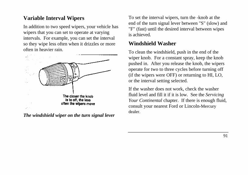
Variable Interval Wipers
In addition to two speed wipers, your vehicle haswipers that you can set to operate at varyingintervals. For example, you can set the intervalso they wipe less often when it drizzles or moreoften in heavier rain.
The windshield wiper on the turn signal lever
To set the interval wipers, turn the -knob at theend of the turn signal lever between "S" (slow) and"F" (fast) until the desired interval between wipesis achieved.
Windshield Washer
To clean the windshield, push in the end of thewiper knob. For a constant spray, keep the knobpushed in. After you release the knob, the wipersoperate for two to three cycles before turning off(if the wipers were OFF) or returning to HI, LO,or the interval setting selected.
If the washer does not work, check the washerfluid level and fill it if it is low. See the ServicingYour Continental chapter. If there is enough fluid,consult your nearest Ford or Lincoln-Mercurydealer.
91
Do not try to clean the windshield when thewasher fluid container is empty or activate thewashers at any time for more than 15 secondscontinuously. This could damage the washerpump system.
/!\ WARNING
In freezing weather, the washer solutionmay freeze on the windshield and obscureyour vision. Always warm up thewindshield with the defroster before youuse the washer fluid. If you cannot seethrough the windshield clearly, it canincrease the risk of being involved in acollision.
For information about refilling the washer fluid orreplacing your windshield wiper blades, seeWindshield washer fluid and Wipers in the Index.
92
Hazard Flasher
The hazard flasher serves as a warning to otherdrivers to be careful when approaching or passingyour vehicle.
The flashers work whether your vehicle is runningor not. The flashers work for up to two hourswhen the battery is fully charged and in goodcondition without draining the battery excessively.If the flashers run for longer than two hours or ifthe battery is not fully charged, the battery can bedrained.
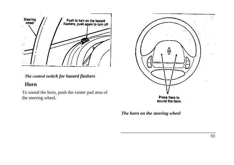
Steering wheel
The control switch for hazard flashers
Horn
To sound the horn, push the center pad area ofthe steering wheel.
Press here to sound the horn
The horn on the steering wheel
93
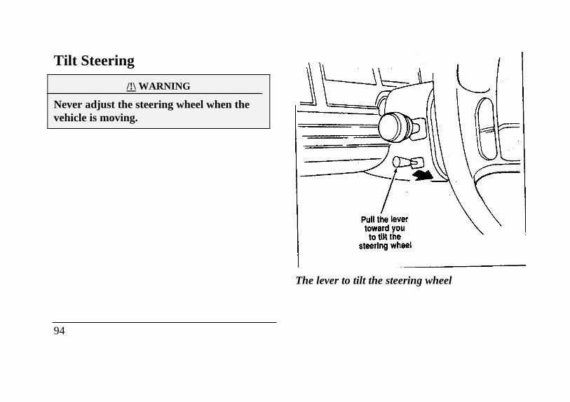
Tilt Steering
/!\ WARNING
Never adjust the steering wheel when thevehicle is moving.
94
The lever to tilt the steering wheel
To change the position of the steering wheel, pullthe release lever on the column toward you. Tipthe steering wheel to the desired position.Release the lever to lock the steering wheel inplace.
Speed ControlYour vehicle has speed control, so you canautomatically maintain a constant speed above 30mph (48 km/h). The switches to operate thespeed control are on the steering wheel.
Use of radio transmitting equipment that is notFederal Communications Commission (FCC) orin Canada the Canadian Radio andTelecommunications Commission (CRTC)approved may cause the speed control tomalfunction. Therefore, use only properlyinstalled FCC (CRTC in Canada) approved radiotransmitting equipment in your vehicle.
NOTE: Since your vehicle has an AutomaticOverdrive Transaxle, you may want to drive in D(Drive) when driving in hilly terrain, at higheraltitudes, or when pulling a trailer. This willimprove speed control performance.
NOTE: Do not shift to N (Neutral) when usingthe speed control. This will cause the engine tooverspeed.
95
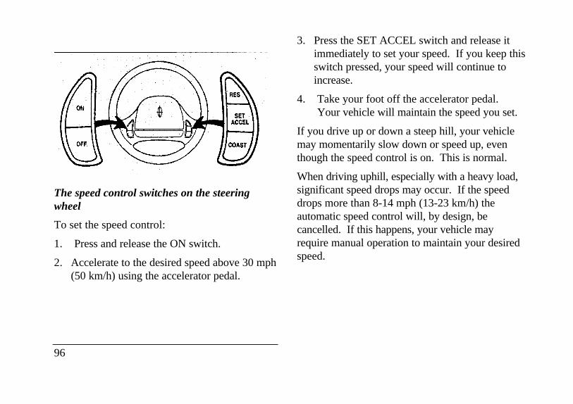
The speed control switches on the steeringwheel
To set the speed control:
1. Press and release the ON switch.
2. Accelerate to the desired speed above 30 mph(50 km/h) using the accelerator pedal.
96
3. Press the SET ACCEL switch and release itimmediately to set your speed. If you keep thisswitch pressed, your speed will continue toincrease.
4. Take your foot off the accelerator pedal.Your vehicle will maintain the speed you set.
If you drive up or down a steep hill, your vehiclemay momentarily slow down or speed up, eventhough the speed control is on. This is normal.
When driving uphill, especially with a heavy load,significant speed drops may occur. If the speeddrops more than 8-14 mph (13-23 km/h) theautomatic speed control will, by design, becancelled. If this happens, your vehicle mayrequire manual operation to maintain your desiredspeed.
NOTE: If your speed increases above your setspeed while driving in (Overdrive) on adownhill grade, you may want to shift to D(Drive) to reduce vehicle speed. The speedcontrol cannot reduce the vehicle speed if it goesabove your set speed on a downhill grade. Forthe best fuel economy during normal drivingconditions, leave the shift select in (Overdrive), or resume as soon as practical.
/!\ WARNING
Do not use the speed control in heavytraffic or on roads that are winding,slippery, or unpaved.
Accelerating With the Speed ControlOperating
You can use the accelerator pedal to speed upmomentarily. When you take your foot off theaccelerator, the vehicle will return to the setspeed.
Resetting the Speed Control
To reset the speed control to a lower speed, use
one of the following procedures:
COAST - Press and hold the COAST switch.Release the switch when the vehicle slows downto the desired speed.
Lightly tap the brake pedal. When the vehicleattains the desired speed, press the SETACCEL switch and release it immediately.
TAP-DOWN - Press and release the COASTswitch momentarily for each m.p.h. (1.6 km/h)reduction in speed desired.
If vehicle speed is reduced below 30 mph (50km/h) by any of the above methods, then you mustmanually accelerate to a speed over 30 mph (50km/h) and reset the system.
97
To reset the speed control to a higher speed,follow one of these procedures:
ACCEL - Press and hold the SET ACCELswitch. Release the switch when the vehiclehas accelerated to the desired speed.
Depress the accelerator pedal. When thevehicle attains the desired speed, press theSET ACCEL switch and release itimmediately.
TAP-UP - Press and release the SET ACCELswitch momentarily for each m.p.h. (1.6 km/h)increase in speed desired.
To Cancel Speed Control
Speed control can be cancelled at any time bypressing the brake pedal slightly. Aftercancelling, you can return to the speed you set bypressing the RES switch, or set a new speed bypressing the SET ACCEL or COAST switches.
98
To Turn Speed Control Off
Press the OFF switch.
Speed control is also turned OFF each time thevehicle ignition is shut off.
Cancelling and Resuming a Set Speed
If you press the brake pedal, speed control issuspended. You can return to the set speed bypressing the RES switch, as long as you did notpress the OFF switch. You must be driving at least30 mph (48 km/h).
Your vehicle will gradually return to the previouslyset speed and then maintain it.
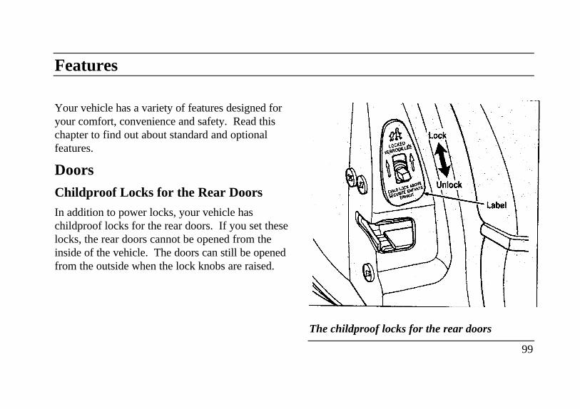
Features
Your vehicle has a variety of features designed foryour comfort, convenience and safety. Read thischapter to find out about standard and optionalfeatures.
DoorsChildproof Locks for the Rear Doors
In addition to power locks, your vehicle haschildproof locks for the rear doors. If you set theselocks, the rear doors cannot be opened from theinside of the vehicle. The doors can still be openedfrom the outside when the lock knobs are raised.
Lock
The childproof locks for the rear doors
99
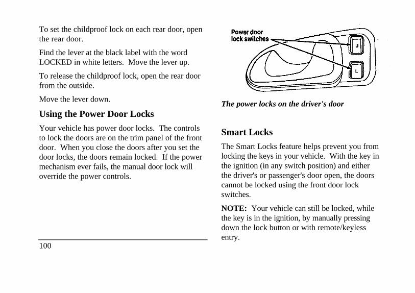
To set the childproof lock on each rear door, openthe rear door.
Find the lever at the black label with the wordLOCKED in white letters. Move the lever up.
To release the childproof lock, open the rear doorfrom the outside.
Move the lever down.
Using the Power Door Locks
Your vehicle has power door locks. The controlsto lock the doors are on the trim panel of the frontdoor. When you close the doors after you set thedoor locks, the doors remain locked. If the powermechanism ever fails, the manual door lock willoverride the power controls.
100
The power locks on the driver's door
Smart Locks
The Smart Locks feature helps prevent you fromlocking the keys in your vehicle. With the key inthe ignition (in any switch position) and eitherthe driver's or passenger's door open, the doorscannot be locked using the front door lockswitches.
NOTE: Your vehicle can still be locked, whilethe key is in the ignition, by manually pressingdown the lock button or with remote/keylessentry.
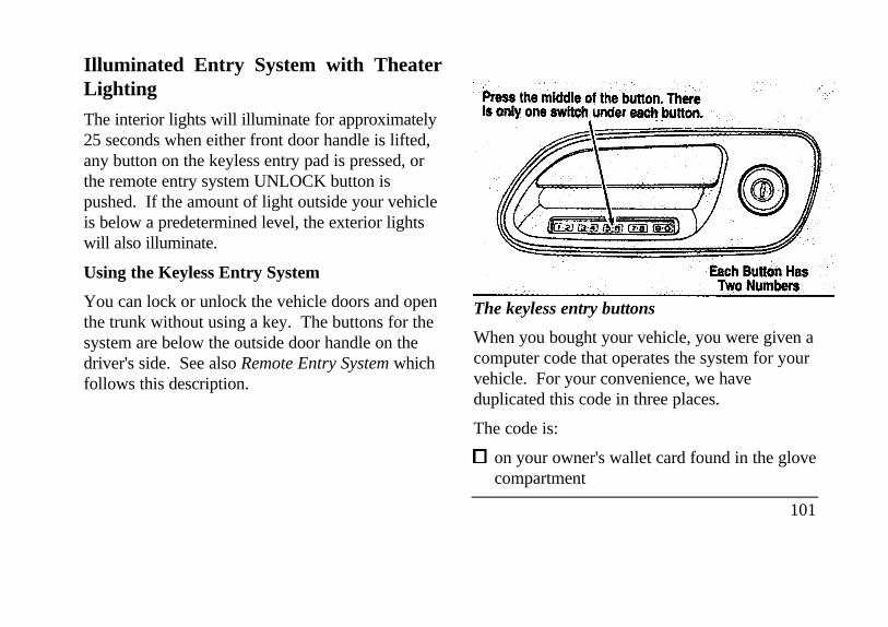
Illuminated Entry System with TheaterLighting
The interior lights will illuminate for approximately25 seconds when either front door handle is lifted,any button on the keyless entry pad is pressed, orthe remote entry system UNLOCK button ispushed. If the amount of light outside your vehicleis below a predetermined level, the exterior lightswill also illuminate.
Using the Keyless Entry System
You can lock or unlock the vehicle doors and openthe trunk without using a key. The buttons for thesystem are below the outside door handle on thedriver's side. See also Remote Entry System whichfollows this description.
The keyless entry buttons
When you bought your vehicle, you were given acomputer code that operates the system for yourvehicle. For your convenience, we haveduplicated this code in three places.
The code is:
on your owner's wallet card found in the glovecompartment
101
taped to the trunk lid's right hinge support bar
taped to the computer module in your driver'sfront door
When you use keyless entry, the illuminated entrysystem turns on the interior lights for 25 secondsand the buttons on the keypad light up. Do notpush the buttons with a key, ballpoint pen, pencil,or any other hard object. These objects coulddamage the buttons.
Unlocking the doors with the keyless entr .ysystem
You must unlock the driver's door before youunlock any of the other doors or trunk. If you letmore than five (5) seconds pass before pressingnumbers, the system shuts down, and you have toenter the code again. The system has shut down ifthe keypad light is out. If the keyless entry systemdoes not work properly, use the key or transmittersto lock and unlock the doors or unlock the trunk.
102
1 To unlock the driver's door, enter the factorycode or your personal code. All codes havefive (5) numbers. After you press the fifthnumber, the driver's door unlocks.
2 To unlock all passenger doors, press the ¾button within five (5) seconds of unlockingthe driver's door or trunk, or re-enter thecode to open the driver's door, then press3/4.
3 To unlock the trunk, press the 5/6 buttonwithin five seconds of unlocking the driver'sor passenger's doors, or re-enter the code toopen the driver's door, then press 5/6.
As long as the driver's door has been unlockedfirst, you can open the passenger door or thetrunk in any order.
Locking the doors with the keyless entry system
Along with unlocking your doors, you can usethe keyless entry system to lock the doors.
To lock all of the vehicle's doors at the same time,press 7/8 and 9/0 at the same time. It is notnecessary to first enter the keypad code. This willalso arm your anti-theft system (if equipped).
Autolock
The Autolock feature will automatically lock all thedoors when:
the vehicle's doors are fully closed
the ignition key is turned to the ON position
someone is sitting in the driver's seat or a heavyobject is placed on it
the vehicle is in a forward gear, and D youexceed three mph (five km/h). The Autolockfeature will repeat when: LI the ignition keyremains in the ON position
someone remains sitting in the driver's seat or aheavy object is on the seat
a door is opened and then closed
the vehicle is in a forward gear, and
you exceed three mph (five km/h).
If you do not want to use the Autolock feature, itcan be deactivated by using the Feature Menu inthe Message Center.
Programming your own entry code
You can program up to three personal codes tounlock your vehicle. These codes do not replacethe permanent code that the dealership gave you.Use your personal code in the same manner asyou would your original code.
To program your own code:
1. Select five digits for your personal code.
2. Enter the factory code that the dealershipgave you.
3. Within five (5) seconds, press 1/2.
103
4. Within five (5) seconds of pressing 1/2, enteryour personal code, pressing each digit withinfive (5) seconds of the previous digit.
5. Enter a sixth digit to indicate which Personalityshould be recalled by this personal code.
1/2 Recall Personality 1
3/4 Recall Personality 2
9/0 No recall
An of the vehicle doors will lock and thenunlock to confirm programming of the newcode.
The keyless entry system registers this new code.To open your vehicle, you can now use either code.
To erase all of the personal entry codes and remoteentry transmitters programmed to a vehicle:
1. Enter the original permanent code.
104
2. Press 1/2 within five (5) seconds of Step I.
3. Press and hold 1/2 for two (2) seconds.
All of the vehicle doors will lock and thenunlock to confirm erasure.
Do not set a code that presents the numbers insequential order, such as 1/2, 3/4, 5/6, 7/8, 9/0.Studies show that people who idly press thebuttons usually press a sequential pattern. Also,do not select a code that uses the same buttonfive times. Thieves can easily figure out thesetypes of codes.
Arming, disarmning and resettirig your anti-theft system (If equipped) from the keylessentry pad
If your vehicle is equipped with the optionalfactory installed anti-theft system, the keylessentry system will arm it when you use the 7/8 and9/0 keys to lock the doors, and will disarm orreset a triggered anti-theft alarm when you enterin the five digit code to unlock the driver's door.
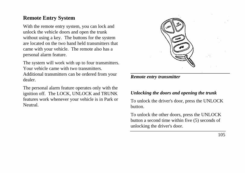
Remote Entry System
With the remote entry system, you can lock andunlock the vehicle doors and open the trunkwithout using a key. The buttons for the systemare located on the two hand held transmitters thatcame with your vehicle. The remote also has apersonal alarm feature.
The system will work with up to four transmitters.Your vehicle came with two transmitters.Additional transmitters can be ordered from yourdealer.
The personal alarm feature operates only with theignition off. The LOCK, UNLOCK and TRUNKfeatures work whenever your vehicle is in Park orNeutral.
Remote entry transmitter
Unlocking the doors and opening the trunk
To unlock the driver's door, press the UNLOCKbutton.
To unlock the other doors, press the UNLOCKbutton a second time within five (5) seconds ofunlocking the driver's door.
105
To open the trunk, press the TRUNK button twicewithin five (5) seconds.
Locking the doors
To lock all the doors, press the LOCK button.This will also arm the anti-theft system (ifequipped).
A programmable door lock horn chirp can beactivated through the message center. Onceactivated, every depression of the lock button willcause the vehicle to honk its horn briefly.
Activating the remote personal alarm
If you wish to activate the remote personal alarm,press the PANIC button. This will honk the hornand flash the low beam headlamps and tail lampsfor approximately two minutes and forty-fiveseconds. You can turn it OFF by pressing thePANIC button again or by turning the ignition keyto the RUN position.
106
Arming and disarming the alarm s system
If your vehicle is equipped with the factoryinstalled anti-theft system, the remote entrysystem will automatically arm it when the doorsare locked with the remote entry LOCK button.The remote entry UNLOCK button will disarmor reset a triggered anti-theft alarm.
The remote entry system is designed to workwith the factory installed anti-theft system. Itmay not work with other anti-theft systems.
Replacing the batteries
The remote entry transmitter is powered by twocoin type three-volt lithium 1616 batteries(included) that should last for several years ofnormal use. If you notice a significant decreasein operating range, the batteries should bereplaced. Replacement batteries can bepurchased at most pharmacies, watch stores or atyour Ford or Lincoln-Mercury dealer.

NOTE: The operating range of the remote entrysystem can also be affected by weather conditions(such as very cold temperatures) or structuresaround the vehicle (buildings, other vehicles, radioand TV towers, etc.). Typical operating range willallow you to be up to 33 feet (10 meters) awayfrom your vehicle.
The transmitter can be snapped apart to replace thebatteries by twisting a thin coin between the twohalves of the transmitter. DO NOT TAKE THEFRONT PART OF THE TRANSMITTERAPART. When installing the new batteries, be sureto place the positive (+) side down as marked.Snap the two halves back together.
Replacement / additional transmitters
In the event a transmitter is lost, a new one may bepurchased from your dealer.
To program replacement or additional transmittersyou must have all the transmitters intended for useon your vehicle.
Initiating the following procedure erases all priorprogrammed transmitters, thus ALL must bereprogrammed at the same time.
1. Enter the factory keyless entry code. Yourpersonal code will not allow programming.
2. Press the 1/2 button.
3. Press one button on each of the transmittersto be programmed. Each transmitter buttonmust be pressed within seven (7) seconds ofthe prior one. Each time a transmitter issuccessfully programmed, all of the vehicledoors will lock and then unlock to verifyprogramming. If the doors did notlock/unlock, your transmitter was notprogrammed.
Additional transmitters may be purchased fromyour dealer (remote entry system will work withup to four transmitters). Follow the sameprogramming procedure as above.
107
THIS DEVICE COMPLIES WITH PART 15OF THE FCC RULES. OPERATION ISSUBJECT TO THE FOLLOWING TWOCONDITIONS: (1) THIS DEVICE MAY NOTCAUSE HARMFUL INTERFERENCE, AND(2) THIS DEVICE MUST ACCEPT ANYINTERFERENCE RECEIVED, INCLUDINGINTERFERENCE THAT MAY CAUSEUNDESIRED OPERATION.
NOTE: All transmitters to be used on your vehiclemust be programmed/reprogrammed at the sametime.
Battery Saver
When the ignition is turned off, the vehicle will turnoff battery voltage to the interior lights after 45minutes.
This will prevent draining of the battery if thoselights have been left on inadvertently or if a door isnot completely closed. BatterV voltage to these
108
lamps will be restored when the outside frontdoor handles are lifted, the keyless entry keypadis used, the remote entry transmitter is used, anydoor is opened, the trunk is opened, or theignition key is turned to the ON position.
Anti-theft System
When armed, this system helps protect yourvehicle against break-ins or theft by monitoringall doors, the hood, and the trunk lock cylinder.
When an unauthorized entry occurs, the systemtriggers and will:
flash the headlamps, parking lamps, interior
lamps, and alarm indicator light
honk the horn
prevent the engine from starting
NOTE: The factory installed Remote EntrySystem has a PANIC feature that also chirps thevehicle horn and flashes the interior/exterior lampswhen the PANIC button on the remote entrytransmitter is pushed. The PANIC alarm and theAnti-Theft alarm are two separate features.Both the anti-theft alarm and the PANIC featurecan be active at the same time.
To tell the difference between a PANIC alarm ancta triggered Anti-Theft alarm:
only the Anti-Theft alarm will cause the alarmindicator light (located in the center of theinstrument cluster) to flash on and off.
only the Anti-Theft alarm will prevent theengine from starting.
For more information on the PANIC alarm, seeRemote Entry System in the Index.
Arming the system
To arm the system, do the following four steps insequence.
1. Remove the key from the ignition.
2. Open any door. The alarm indicator lightwill start flashing to remind you to arm thesystem.
3. Lock the doors by using the power door lockswitch, pressing the remote entry transmitterLOCK button or pressing the last twobuttons (7/8, 9/0) of the keyless entrykeypad.
The alarm indicator will now glow steadily.
4. Close all doors. The alarm indicator lightwill then remain on steadily forapproximately 30 more seconds and then goout. When the light goes out the system isarmed.
109
NOTE: Be sure to close all doors completely. Ifnot, the alarm indicator light will remain on.Remember, your anti-theft system is armed onlyafter the alarm indicator light remains on steadilyfor approximately 30 seconds after the last door isclosed, and then goes out.
You can also arm the anti-theft system with thefactory installed remote entry system or the keylessentry system by following this sequence:
1. Remove key from ignition.
2. Close all of the doors.
3. Press the remote entry transmitter LOCKbutton or press the last two buttons (7/8, 9/0)of the keyless entry keypad to lock the doors.The alarm indicator will come on for 30seconds to show the alarm is arming and thenturn off to show that the alarm has armed.
110
The anti-theft system is designed to work withthe factory installed remote entry system. It maynot work with other remote entry systems.
NOTE: The anti-theft system will not activatewhfle someone is sitting in the driver's seat or ifthere is a heavy object in the driver's seat.
Disarming an untriggered anti-theft system
You can disarm the system by:
unlocking a front door with the key (turn thekey all the way to the end of travel or thesystem will not disarm).
using the keyless entry unlock code.
using the UNLOCK button of the remoteentry transmitter.
If you armed the system while inside yourvehicle, you can disarm it by turning the ignitionto the ON or ACC position. This allows you toopen the door and exit without triggering thesystem.
Triggering the alarm system
The armed system will be triggered if:
any door is opened without disarming thesystem (see previous paragraphs), or
the trunk lock cylinder is removed, or
NOTE: You can open the trunk with your keywithout setting off the alarm.
the hood is opened.
Disarming a triggered system
The alarm can be disarmed by:
unlocking a front door with the key
using the keyless entry unlock code
using the UNLOCK button of the remote entrytransmitter
NOTE: The flashing lights and honking hornwill shut off automatically approximatelythree minutes after the system is triggered.It will trigger again if another intrusionoccurs. However, the engine will not beallowed to start until the system is disarmed.
Windows
Using the Power Windows
Each door has a power control that opens andcloses the window on that door. The driver'sdoor has a master control panel that operates allfour windows.
Power windows can only be opened or closedwhen the ignition is in the ON or ACC positionor during the ten minute delayed accessoryperiod after the ignition is turned off.
111
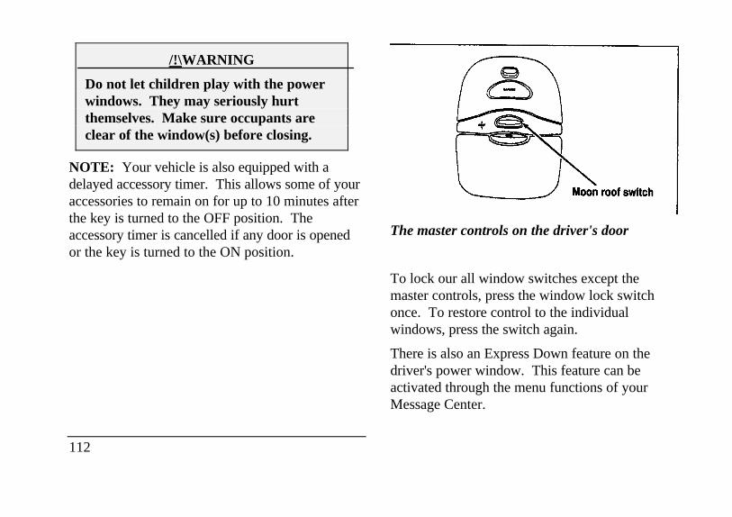
/!\WARNING
Do not let children play with the powerwindows. They may seriously hurtthemselves. Make sure occupants areclear of the window(s) before closing.
NOTE: Your vehicle is also equipped with adelayed accessory timer. This allows some of youraccessories to remain on for up to 10 minutes afterthe key is turned to the OFF position. Theaccessory timer is cancelled if any door is openedor the key is turned to the ON position.
112
The master controls on the driver's door
To lock our all window switches except themaster controls, press the window lock switchonce. To restore control to the individualwindows, press the switch again.
There is also an Express Down feature on thedriver's power window. This feature can beactivated through the menu functions of yourMessage Center.
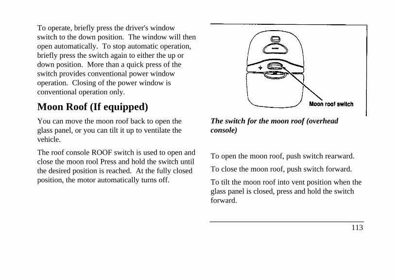
To operate, briefly press the driver's windowswitch to the down position. The window will thenopen automatically. To stop automatic operation,briefly press the switch again to either the up ordown position. More than a quick press of theswitch provides conventional power windowoperation. Closing of the power window isconventional operation only.
Moon Roof (If equipped)You can move the moon roof back to open theglass panel, or you can tilt it up to ventilate thevehicle.
The roof console ROOF switch is used to open andclose the moon rool Press and hold the switch untilthe desired position is reached. At the fully closedposition, the motor automatically turns off.
The switch for the moon roof (overheadconsole)
To open the moon roof, push switch rearward.
To close the moon roof, push switch forward.
To tilt the moon roof into vent position when theglass panel is closed, press and hold the switchforward.
113
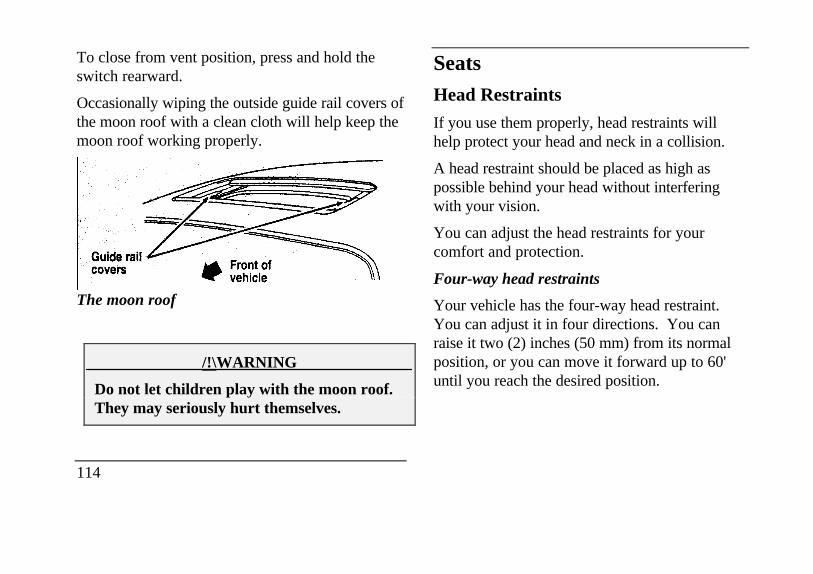
To close from vent position, press and hold theswitch rearward.
Occasionally wiping the outside guide rail covers ofthe moon roof with a clean cloth will help keep themoon roof working properly.
The moon roof
/!\WARNING
Do not let children play with the moon roof.They may seriously hurt themselves.
114
SeatsHead Restraints
If you use them properly, head restraints willhelp protect your head and neck in a collision.
A head restraint should be placed as high aspossible behind your head without interferingwith your vision.
You can adjust the head restraints for yourcomfort and protection.
Four-way head restraints
Your vehicle has the four-way head restraint.You can adjust it in four directions. You canraise it two (2) inches (50 mm) from its normalposition, or you can move it forward up to 60'until you reach the desired position.
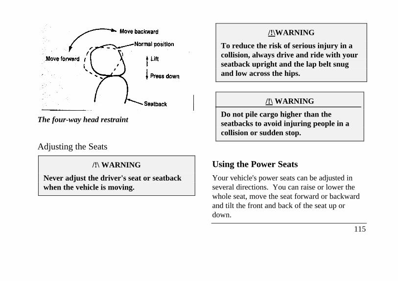
The four-way head restraint
Adjusting the Seats
/!\ WARNING
Never adjust the driver's seat or seatbackwhen the vehicle is moving.
/!\WARNING
To reduce the risk of serious injury in acollision, always drive and ride with yourseatback upright and the lap belt snugand low across the hips.
/!\ WARNING
Do not pile cargo higher than theseatbacks to avoid injuring people in acollision or sudden stop.
Using the Power Seats
Your vehicle's power seats can be adjusted inseveral directions. You can raise or lower thewhole seat, move the seat forward or backwardand tilt the front and back of the seat up ordown.
115
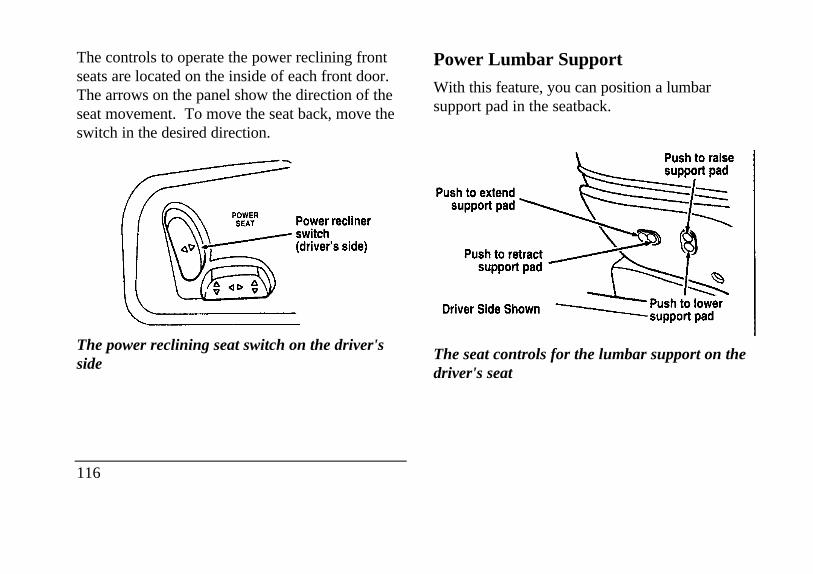
The controls to operate the power reclining frontseats are located on the inside of each front door.The arrows on the panel show the direction of theseat movement. To move the seat back, move theswitch in the desired direction.
The power reclining seat switch on the driver'sside
116
Power Lumbar Support
With this feature, you can position a lumbarsupport pad in the seatback.
The seat controls for the lumbar support on thedriver's seat
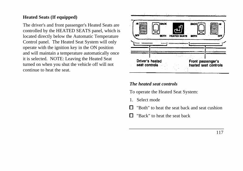
Heated Seats (If equipped)
The driver's and front passenger's Heated Seats arecontrolled by the HEATED SEATS panel, which islocated directly below the Automatic TemperatureControl panel. The Heated Seat System will onlyoperate with the ignition key in the ON positionand will maintain a temperature automatically onceit is selected. NOTE: Leaving the Heated Seatturned on when you shut the vehicle off will notcontinue to heat the seat.
heated seat controls
The heated seat controls
To operate the Heated Seat System:
1. Select mode
"Both" to heat the seat back and seat cushion
"Back" to heat the seat back
117
2. Rotate the thumbwheel from "0" to " 1 " (thelowest heat level). Allow five minutes for theheat level to stabilize.
3. If the heat level is not high enough for comfort,select increased heat levels "2' through "5" (themaximum level). Allow at least two minutesfor the heat level to stabilize at any new levelselected.
4. If the heated seat switch is not turned off ("0"on the thumbwheel), the seat will heat up to theselected temperature level each time the car isstarted.
NOTE: Cooling the seat down takes considerablylonger than increasing its heat level.
118
Cleaning the Seats
Leather
For routine cleaning, wipe the surface with asoft, damp cloth. For more thorough cleaning,wipe the surface with a leather and vinyl cleaneror a mild soap.
Wipe the surface with a damp, soft cloth, thendry and buff with a dry, soft cloth.
Fabric
Remove dust and loose dirt with a whisk broomor a vacuum cleaner. Remove fresh spotsimmediately. Follow the directions that comewith the cleaner.
NOTE: Before using any cleaner, test it on asmall, hidden area of fabric. If the fabric's coloror texture is adversely affected by a particularcleaner, do not use it.
Memory Profile SystemThe Personality Memory Feature customizes yourContinental for up to two (2) drivers. Thefollowing features are automatically recalled whenunlocking the doors using the remote entrytransmitter, keyless entry keypad, or by pressingthe Memory 1 or Memory 2 switches on thedriver's door:
All driver's seat positions except power lumbarand head restraint.
Both left and right outside mirror settings.
Radio station presets including the last selectedstation and band and 0 preset preferences onFMI, FM2, and AM.
Instrument panel dimming setting.
Autolamp delay time-out setting.
Ride/Steering menu setting.
Feature Menu settings
The Ride/Steering menu is located in theMessage Center. The RIDE display allows youto adjust the suspension feel to FIRM,NORMAL, or PLUSH.
Pressing the Ride/Steering menu switch againbrings the STEERING display. This allows youto adjust steering effort to LOW, NORMAL, orHIGH.
For more information on ride/steering options,see Road Calibrated Suspension later in thischapter.
Personality Memory also allows you tocustomize settings from the Feature menulocated in the Message Center. The Featuremenu contains five (5) features that you canenable or disable. The features are listed in theorder they appear in the Feature menu.
EXPRESS WINDOW - for one tap downoperation of the driver's window.
119
AUTO DOOR LOCKS - automatically locks alldoors when the driver shifts out of PARK, alldoors are closed, and the vehicle speed is atleast three mph (five km/h).
HORN CHIRP - sounds an audible "chirp"when you press the LOCK button on the remoteentry transmitter to verify that the doors havebeen locked and the vehicle's anti-theft systemhas been armed (if equipped).
SEAT ACCESS - moves the driver's seat backtwo (2) inches or to the end of the seat trackwhen the vehicle is turned off and the ignitionkey is removed. Upon the driver entering thevehicle and closing the door, the seat will moveforward to its previous position.
REVERSE MIRROR - when the vehicle isshifted to REVERSE, the outside rearviewmirrors tilt down. This provides an improvedview of the side of the vehicle and curb areawhen backing up. When you shift out ofREVERSE, the mirrors return to their previouspositions.
120
Recalling Personality Memory
All of these settings are automatically recalledwhen the driver unlocks the door using theremote entry transmitter, keyless entry keypad orpresses either Memory I or Memory 2 switchinside the driver's door. The vehicle must be inPARK or NEUTRAL to recall PersonalityMemory settings.
Remote Entry
Pressing the UNLOCK button on the remoteentry transmitter unlocks the driver's door andrecalls all of the Personality Memory settings.Two transmitters are delivered with the vehicle.One is programmed to always recall Memory Iand the other will always recall Memory 2.Personality Memory 1 or 2 is indicated on theback of the transmitter.
Personality Memory recall from the remotetransmitter can be disabled. This is done by slidingthe switch on the back of the transmitter to OFF.Personality Memory can still be recalled using
keyless entry code or the Memory I or Memory 2switches.
Keyless Entry
Up to three unique keyless entry codes can beprogrammed by the customer. Two of the codescan be assigned to recall Personality Memory I orMemory 2. Each time the 5-digit code is entered onthe keypad, the driver's door will unlock andPersonality Memory 1 or Memory 2 will berecalled.
NOTE: Please note that even though the driver'sPersonality Memory may be recalled using remoteor keyless entry, the seats and mirrors will notmove to the driver's set positions until the driver'sdoor is opened.
Memory Switches
Pressing either the Memory I or Memory 2 switchon the driver's door will also recall the PersonalityMemory settings as selected, providing yourvehicle is in P (Park) or N (Neutral).
Auto Save
Any change made by the driver to one of theabove Personality Memory settings will beupdated and saved automatically. The display,SAVED TO DRIVER I or SAVED TODRIVER 2, will appear on the Message Centerfor five (5) seconds as a confirmation of theupdate to Personality Memory. If a radio presetis changed the radio display will also showSAVED.
If the driver does not use the remote entrytransmitter, or keyless entry keypad to unlock thedoors upon entering or does not press theMemory I or Memory 2 switch, then any changeto one of the Personality Memory settings(except radio presets) will not be automaticallysaved. Instead the driver will be prompted by theMessage Center whether to save the settings toDriver 1 or Driver 2.
121
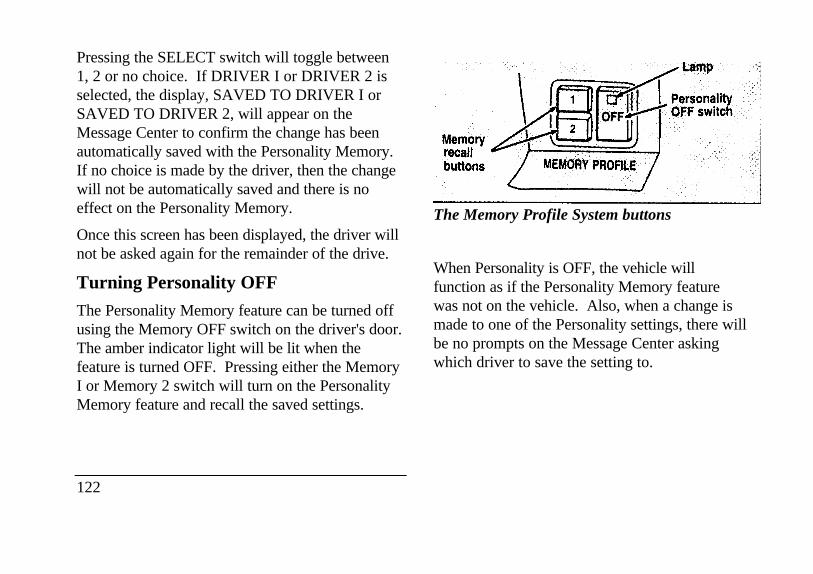
Pressing the SELECT switch will toggle between1, 2 or no choice. If DRIVER I or DRIVER 2 isselected, the display, SAVED TO DRIVER I orSAVED TO DRIVER 2, will appear on theMessage Center to confirm the change has beenautomatically saved with the Personality Memory.If no choice is made by the driver, then the changewill not be automatically saved and there is noeffect on the Personality Memory.
Once this screen has been displayed, the driver willnot be asked again for the remainder of the drive.
Turning Personality OFF
The Personality Memory feature can be turned offusing the Memory OFF switch on the driver's door.The amber indicator light will be lit when thefeature is turned OFF. Pressing either the MemoryI or Memory 2 switch will turn on the PersonalityMemory feature and recall the saved settings.
122
Memory recall buttons
The Memory Profile System buttons
When Personality is OFF, the vehicle willfunction as if the Personality Memory featurewas not on the vehicle. Also, when a change ismade to one of the Personality settings, there willbe no prompts on the Message Center askingwhich driver to save the setting to.
Road Calibrated SuspensionYour Continental is equipped with a ride controlsystem that is designed to read disturbances in theroad surface every six inches at 60 mph (100 km/h)to provide you with optimal driving response.
Ride control allows you to chose both a ride feeland steering effort that best flts your personaldriving style. These options may be selected byusing the RIDE/STEER Message Center button.
Pressing this button once will allow you to adjustyour RIDE CONTROL settings, betweenNORMAL, PLUSH and FIRM. The settings arechanged by pressing the SELECT button whileRIDE CONTROL is displayed.
Pressing the RIDE/STEER button a second timewill allow you to adjust the STEERINGEFFORT settings between NORMAL, LOW,and HIGH. The settings are changed by pressingthe SELECT button while STEERING EFFORTis displayed.
123
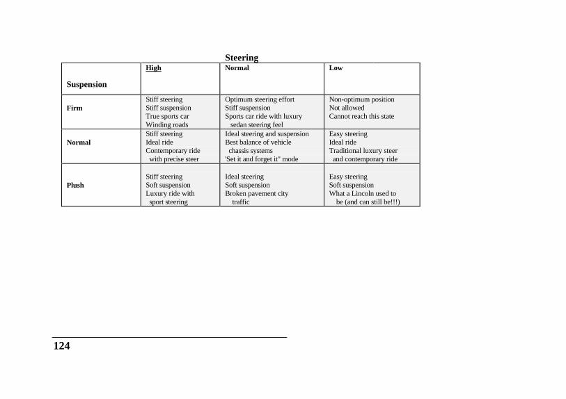
Steering
Suspension
High Normal Low
FirmStiff steeringStiff suspensionTrue sports carWinding roads
Optimum steering effortStiff suspensionSports car ride with luxury sedan steering feel
Non-optimum positionNot allowedCannot reach this state
NormalStiff steeringIdeal rideContemporary ride with precise steer
Ideal steering and suspensionBest balance of vehicle chassis systems'Set it and forget it" mode
Easy steeringIdeal rideTraditional luxury steer and contemporary ride
PlushStiff steeringSoft suspensionLuxury ride with sport steering
Ideal steeringSoft suspensionBroken pavement city traffic
Easy steeringSoft suspensionWhat a Lincoln used to be (and can still be!!!)
124
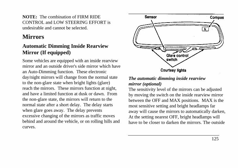
NOTE: The combination of FIRM RIDECONTROL and LOW STEERING EFFORT isundesirable and cannot be selected.
MirrorsAutomatic Dimming Inside RearviewMirror (If equipped)
Some vehicles are equipped with an inside rearviewmirror and an outside driver's side mirror which havean Auto-Dimming function. These electronicday/night mirrors will change from the normal stateto the non-glare state when bright lights (glare)reach the mirrors. These mirrors function at night,and have a limited function at dusk or dawn. Fromthe non-glare state, the mirrors will return to thenormal state after a short delay. The delay startswhen glare goes away. The delay preventsexcessive changing of the mirrors as traffic movesbehind and around the vehicle, or on rolling hills andcurves.
The automatic dimming inside rearviewmirror (optional)The sensitivity level of the mirrors can be adjustedby moving the switch on the inside rearview mirrorbetween the OFF and MAX positions. MAX is themost sensitive setting and bright headlamps faraway will cause the mirrors to automatically darken,At the setting nearest OFF, bright headlamps willhave to be closer to darken the mirrors. The outside
125
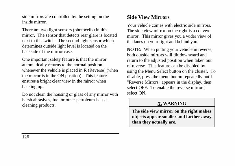
side mirrors are controlled by the setting on theinside mirror.
There are two light sensors (photocells) in thismirror. The sensor that detects rear glare is locatednext to the switch. The second light sensor whichdetermines outside light level is located on thebackside of the mirror case.
One important safety feature is that the mirrorautomatically returns to the normal positionwhenever the vehicle is placed in R (Reverse) (whenthe mirror is in the ON position). This featureensures a bright clear view in the mirror whenbacking up.
Do not clean the housing or glass of any mirror withharsh abrasives, fuel or other petroleum-basedcleaning products.
126
Side View Mirrors
Your vehicle comes with electric side mirrors.The side view mirror on the right is a convexmirror. This mirror gives you a wider view ofthe lanes on your right and behind you.
NOTE: When putting your vehicle in reverse,both outside mirrors will tilt downward andreturn to the adjusted position when taken outof reverse. This feature can be disabled byusing the Menu Select button on the cluster. Todisable, press the menu button repeatedly until"Reverse Mirrors" appears in the display, thenselect OFF. To enable the reverse mirrors,select ON.
/!\ WARNING
The side view mirror on the right makesobjects appear smaller and farther awaythan they actually are.
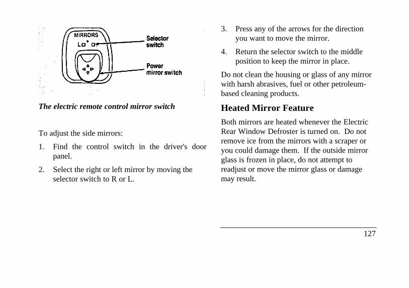
power mirror switch selector switch
The electric remote control mirror switch
To adjust the side mirrors:
1. Find the control switch in the driver's doorpanel.
2. Select the right or left mirror by moving theselector switch to R or L.
3. Press any of the arrows for the directionyou want to move the mirror.
4. Return the selector switch to the middleposition to keep the mirror in place.
Do not clean the housing or glass of any mirrorwith harsh abrasives, fuel or other petroleum-based cleaning products.
Heated Mirror Feature
Both mirrors are heated whenever the ElectricRear Window Defroster is turned on. Do notremove ice from the mirrors with a scraper oryou could damage them. If the outside mirrorglass is frozen in place, do not attempt toreadjust or move the mirror glass or damagemay result.
127
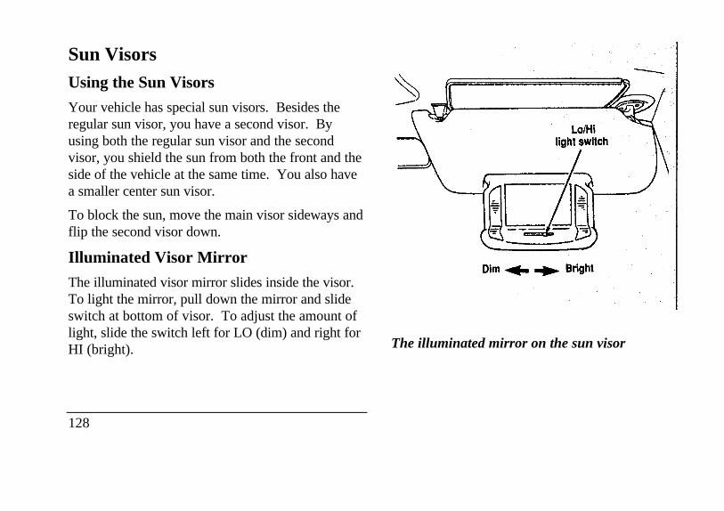
Sun VisorsUsing the Sun Visors
Your vehicle has special sun visors. Besides theregular sun visor, you have a second visor. Byusing both the regular sun visor and the secondvisor, you shield the sun from both the front and theside of the vehicle at the same time. You also havea smaller center sun visor.
To block the sun, move the main visor sideways andflip the second visor down.
Illuminated Visor Mirror
The illuminated visor mirror slides inside the visor.To light the mirror, pull down the mirror and slideswitch at bottom of visor. To adjust the amount oflight, slide the switch left for LO (dim) and right forHI (bright).
128
Lo/HI light switch Dim Bright
The illuminated mirror on the sun visor
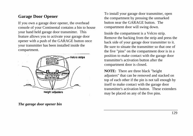
Garage Door Opener
If you own a garage door opener, the overheadconsole of your Continental contains a bin to houseyour hand held garage door transmitter. Thisfeature allows you to activate your garage dooropener with a push of the GARAGE button onceyour transmitter has been installed inside thecompartment.
Heightadjusters Velcro strips
The garage door opener bin
To install your garage door transmitter, openthe compartment by pressing the unmarkedbutton near the GARAGE button. Thecompartment door will swing down.
Inside the compartment is a Velcro strip.Remove the backing from the strip and press theback side of your garage door transmitter to it.Be sure to situate the transmitter so that one ofthe five "pins" on the compartment door is in aposition to make contact with the garage doortransmitter's activation button after thecompartment door is closed.
NOTE: There are three black "heightadjusters" that can be removed and stacked ontop of each other if the pin is not tall enough byitself to make contact with the garage doortransmitter's activation button. These extendersmay be placed on any of the five pins.
129
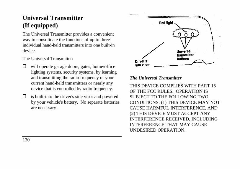
Universal Transmitter(If equipped)The Universal Transmitter provides a convenientway to consolidate the functions of up to threeindividual hand-held transmitters into one built-indevice.
The Universal Transmitter:
will operate garage doors, gates, home/officelighting systems, security systems, by learningand transmitting the radio frequency of yourcurrent hand-held transmitters or nearly anydevice that is controlled by radio frequency.
is built-into the driver's side visor and poweredby your vehicle's battery. No separate batteriesare necessary.
130
Red light Universal transmitter button Driver's sun visor
The Universal Transmitter
THIS DEVICE COMPLIES WITH PART 15OF THE FCC RULES. OPERATION ISSUBJECT TO THE FOLLOWING TWOCONDITIONS: (1) THIS DEVICE MAY NOTCAUSE HARMFUL INTERFERENCE, AND(2) THIS DEVICE MUST ACCEPT ANYINTERFERENCE RECEIVED, INCLUDINGINTERFERENCE THAT MAY CAUSEUNDESIRED OPERATION.
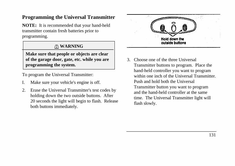
Programming the Universal Transmitter
NOTE: It is recommended that your hand-heldtransmitter contain fresh batteries prior toprogramming.
/!\ WARNING
Make sure that people or objects are clearof the garage door, gate, etc. while you areprogramming the system.
To program the Universal Transmitter:
I. Make sure your vehicle's engine is off.
2. Erase the Universal Transmitter's test codes byholding down the two outside buttons. After20 seconds the light will begin to flash. Releaseboth buttons immediately.
3. Choose one of the three UniversalTransmitter buttons to program. Place thehand-held controller you want to programwithin one inch of the Universal Transmitter.Push and hold both the UniversalTransmitter button you want to programand the hand-held controller at the sametime. The Universal Transmitter light willflash slowly.
131
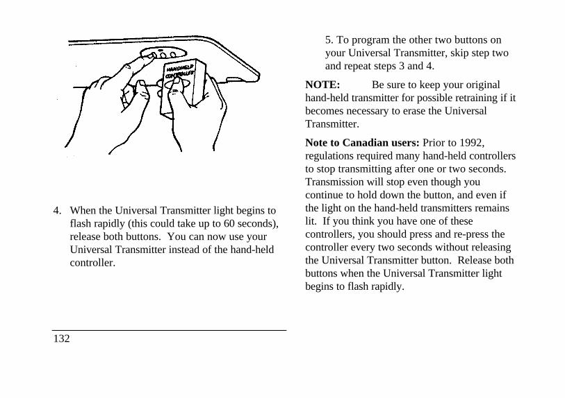
4. When the Universal Transmitter light begins toflash rapidly (this could take up to 60 seconds),release both buttons. You can now use yourUniversal Transmitter instead of the hand-heldcontroller.
132
5. To program the other two buttons onyour Universal Transmitter, skip step twoand repeat steps 3 and 4.
NOTE: Be sure to keep your originalhand-held transmitter for possible retraining if itbecomes necessary to erase the UniversalTransmitter.
Note to Canadian users: Prior to 1992,regulations required many hand-held controllersto stop transmitting after one or two seconds.Transmission will stop even though youcontinue to hold down the button, and even ifthe light on the hand-held transmitters remainslit. If you think you have one of thesecontrollers, you should press and re-press thecontroller every two seconds without releasingthe Universal Transmitter button. Release bothbuttons when the Universal Transmitter lightbegins to flash rapidly.
Operating the Universal Transmitter
/!\ WARNING
Do not use the Universal Transmitter with anygarage door opener that lacks safety "stop"and "reverse" features as required by federalstandards.
To operate, press the appropriate button on theUniversal Transmitter. The light will illuminatewhile the signal is being transmitted.
NOTE: The effective transmission range ofthe Universal Transmitter may differ from yourhand-held transmitter.
Erasing the Universal TransmitterChannels
To clear the Universal Transmitter of all threepreviously stored frequencies, follow Step 2 ofthe Programming the Universal Transmittersection.
Console
Your vehicle may have a full console. The fullconsole has the following features:
133
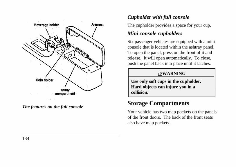
Utility compartment armrest utility compartment beverage holder
The features on the full console
134
Cupholder with full console
The cupholder provides a space for your cup.
Mini console cupholders
Six passenger vehicles are equipped with a miniconsole that is located within the ashtray panel.To open the panel, press on the front of it andrelease. It will open automatically. To close,push the panel back into place until it latches.
/!\WARNING
Use only soft cups in the cupholder.Hard objects can injure you in acollision.
Storage CompartmentsYour vehicle has two map pockets on the panelsof the front doors. The back of the front seatsalso have map pockets.
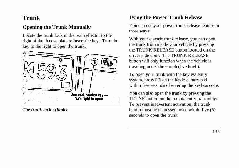
TrunkOpening the Trunk Manually
Locate the trunk lock in the rear reflector to theright of the license plate to insert the key. Turn thekey to the right to open the trunk.
The trunk lock cylinder
Using the Power Trunk Release
You can use your power trunk release feature inthree ways:
With your electric trunk release, you can openthe trunk from inside your vehicle by pressingthe TRUNK RELEASE button located on thedriver side door. The TRUNK RELEASEbutton will only function when the vehicle istraveling under three mph (five km/h).
To open your trunk with the keyless entrysystem, press 5/6 on the keyless entry padwithin five seconds of entering the keyless code.
You can also open the trunk by pressing theTRUNK button on the remote entry transmitter.To prevent inadvertent activation, the trunkbutton must be depressed twice within five (5)seconds to open the trunk.
135
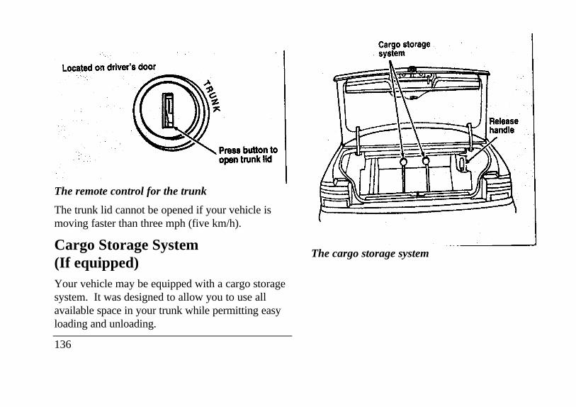
open trunk lid
The remote control for the trunk
The trunk lid cannot be opened if your vehicle ismoving faster than three mph (five km/h).
Cargo Storage System(If equipped)Your vehicle may be equipped with a cargo storagesystem. It was designed to allow you to use allavailable space in your trunk while permitting easyloading and unloading.
136
The cargo storage system
Release handle
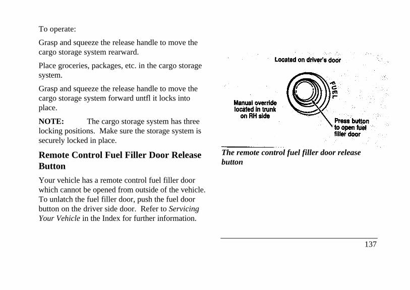
To operate:
Grasp and squeeze the release handle to move thecargo storage system rearward.
Place groceries, packages, etc. in the cargo storagesystem.
Grasp and squeeze the release handle to move thecargo storage system forward untfl it locks intoplace.
NOTE: The cargo storage system has threelocking positions. Make sure the storage system issecurely locked in place.
Remote Control Fuel Filler Door ReleaseButton
Your vehicle has a remote control fuel filler doorwhich cannot be opened from outside of the vehicle.To unlatch the fuel filler door, push the fuel doorbutton on the driver side door. Refer to ServicingYour Vehicle in the Index for further information.
Located on driver's door Manual override
located in trunk on RH side
Press button to open fuel filler
door
The remote control fuel filler door releasebutton
137
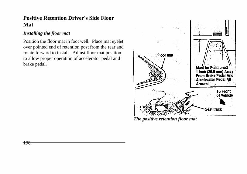
Positive Retention Driver's Side FloorMat
Installing the floor mat
Position the floor mat in foot well. Place mat eyeletover pointed end of retention post from the rear androtate forward to install. Adjust floor mat positionto allow proper operation of accelerator pedal andbrake pedal.
138
Must be Positioned 1 inch (25.5 mm) Away From Brake Pedal And Accelerator Pedal All Around To Front ofVehicle Seat track floor mat
The positive retention floor mat
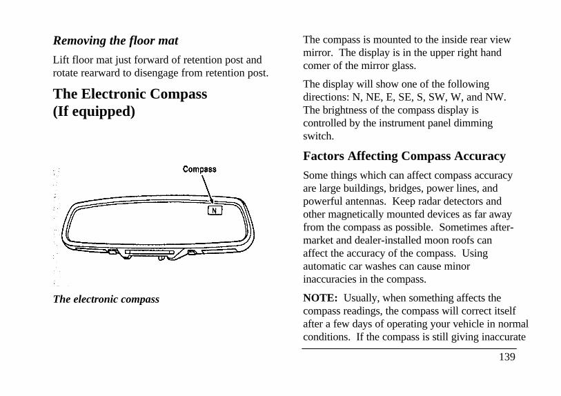
Removing the floor mat
Lift floor mat just forward of retention post androtate rearward to disengage from retention post.
The Electronic Compass(If equipped)
The electronic compass
The compass is mounted to the inside rear viewmirror. The display is in the upper right handcomer of the mirror glass.
The display will show one of the followingdirections: N, NE, E, SE, S, SW, W, and NW.The brightness of the compass display iscontrolled by the instrument panel dimmingswitch.
Factors Affecting Compass Accuracy
Some things which can affect compass accuracyare large buildings, bridges, power lines, andpowerful antennas. Keep radar detectors andother magnetically mounted devices as far awayfrom the compass as possible. Sometimes after-market and dealer-installed moon roofs canaffect the accuracy of the compass. Usingautomatic car washes can cause minorinaccuracies in the compass.
NOTE: Usually, when something affects thecompass readings, the compass will correct itselfafter a few days of operating your vehicle in normalconditions. If the compass is still giving inaccurate
139
readings after a few days, perform a compassadjustment.
Compass-Calibration
I . For optimum calibration, switch off all non-essential electrical accessories (rear windowdefrost, heater/air conditioning, map lamps,wipers, etc.) and ensure all doors are shut.
2. Drive to an open, level area away from largemetallic objects or structures.
3. Insert an appropriate diameter rod (paper clip)into the left switch access hole underneath thecompass module and press gently for 1-2seconds until "CAL" and a direction appear onthe display.
140
4. Release the button and drive in a circleuntil "CAL" disappears from the display(approx. 2-3 circles).
Compass-Zone Adjustment
1. The zone setting is factory pre-set to Zone8. Refer to the Zone Map in this manual toverify the correct compass zone setting foryour geographical location.
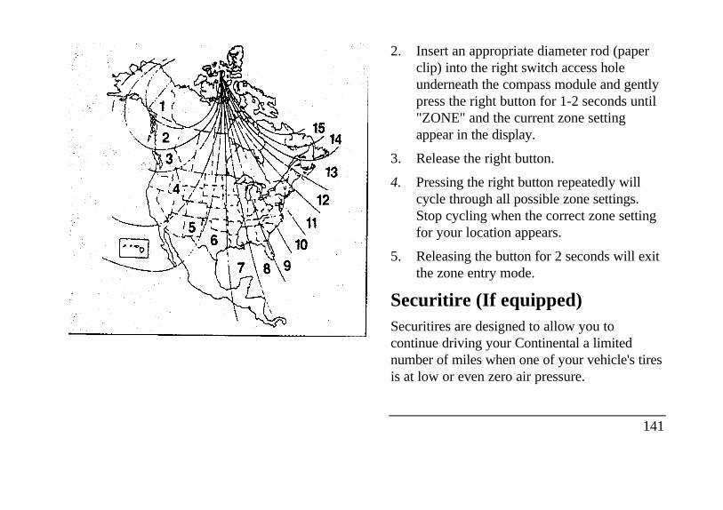
2. Insert an appropriate diameter rod (paperclip) into the right switch access holeunderneath the compass module and gentlypress the right button for 1-2 seconds until"ZONE" and the current zone settingappear in the display.
3. Release the right button.
4. Pressing the right button repeatedly willcycle through all possible zone settings.Stop cycling when the correct zone settingfor your location appears.
5. Releasing the button for 2 seconds will exitthe zone entry mode.
Securitire (If equipped)Securitires are designed to allow you tocontinue driving your Continental a limitednumber of miles when one of your vehicle's tiresis at low or even zero air pressure.
141
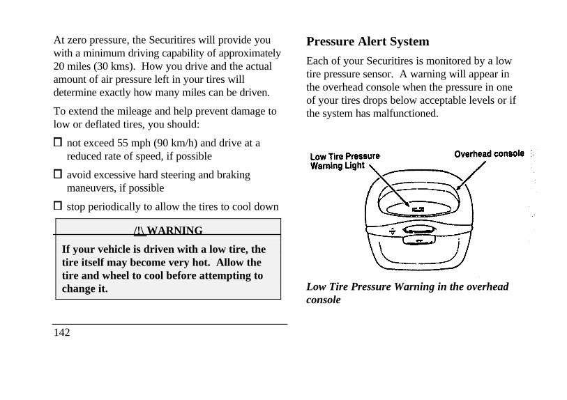
At zero pressure, the Securitires will provide youwith a minimum driving capability of approximately20 miles (30 kms). How you drive and the actualamount of air pressure left in your tires willdetermine exactly how many miles can be driven.
To extend the mileage and help prevent damage tolow or deflated tires, you should:
not exceed 55 mph (90 km/h) and drive at areduced rate of speed, if possible
avoid excessive hard steering and brakingmaneuvers, if possible
stop periodically to allow the tires to cool down
/!\ WARNING
If your vehicle is driven with a low tire, thetire itself may become very hot. Allow thetire and wheel to cool before attempting tochange it.
142
Pressure Alert System
Each of your Securitires is monitored by a lowtire pressure sensor. A warning will appear inthe overhead console when the pressure in oneof your tires drops below acceptable levels or ifthe system has malfunctioned.
Low Tire Pressure Warning Light Overhead
console
Low Tire Pressure Warning in the overheadconsole
THIS DEVICE COMPLIES WITH FCC RULES,PART 15. OPERATION IS SUBJECT TO THEFOLLOWING TWO CONDITIONS: (1) THISDEVICE MAY NOT CAUSE HARMFULINTEREFERENCE AND (2) THIS DEVICEMUST ACCEPT ANY INTEREFERENCE THATMAY BE RECEIVED, INCLUDINGINTEREFERENCE THAT MAY CAUSEUNDESIRABLE OPERATION.
Maintenance Warning
The "Low Tire Pressure" warning will illuminateand stay on when one of your vehicle's tires dropsbelow 18 psi (124 kps). The warning light will alsocome on and stay lit if the Pressure Alert System hasmalfunctioned.
If this warning appears, check the pressure in yourtires at the earliest possible convenience and adjustany tire that is low to the recommended air pressurelevel. This information can be found on the ServiceStation Information page at the back of this manualor on the driver's door placard.
If the warning remains on after you haveadjusted the tires to recommended air pressurelevels, take your vehicle to an authorizedLincoln/Mercury dealer for service.
Flat Tire Warning
If the sensors detect a tire pressure lower than I0 psi (68 kps), the "Low Tire Pressure" warningwill flash repeatedly in the overhead console andthe message "Warning Low Tire Pressure" willbe displayed in the Message Center, indicatingan impending flat tire. If this condition occurs,your Securitire requires service as soon aspossible. Refer to Servicing Your Secutitires.
NOTE: The Pressure Alert System willactivate only when the vehicle is moving fasterthan 10 mph (15 km/h).
143
Servicing Your Securitires
/!\ WARNING
Do not use aerosol tire inflator/sealer withSecuritires. Doing so may damage the tire'spressure sensor.
If you cannot service your Securitire immediately,replace it with your mini-spare as soon as it is safeto do so.
Your mini-spare tire can be used until yourSecuritire has been repaired. See Tires in theServicing chapter of this guide for more informationon using the spare.
It is recommended that you always have yourSecuritires serviced by an authorized Michelin tiredealer. Each Securitire is equipped with apressure sensor around the wheel rim. Thissensor could be damaged when removing andinstalling the tire. Servicing a Securitire at
144
locations other than your Michelin tire dealerlmay adversely affect your warranty.
If you have questions concerning yourSecuritires or servicing, please call the MichelinTire Information Line at 1-800-847-3435 orcontact your local Michelin tire dealer.
Lincoln RESCU System(If equipped)
/!\ WARNING
It is important that you understand thelimitations of your Lincoln RESCUSystem prior to initiating an activation.See Lincoln RESCU System Limitationslater in this chapter for details.
Quick Summary
To utilize your vehicle's assistance requestfeature, YOUR CELLULAR PHONE MUST BEACTIVATED.
Roadside or emergency assistance can berequested whenever your key is in theRUN/START position and for two minutes afterthe vehicle is turned off.
An assistance request is initiated by pressingeither the tow truck or ambulance button locatedin the overhead console.
When a button is pressed, a warning lamp locatedin the overhead console begins to flash and statusmessages are displayed on the vehicle's messagecenter. (Messages are only displayed when yourkey is in the RUN/START position.)
The vehicle's cellular phone automaticallyplaces a call to a 24 hour emergencyresponse center.
When contact is made, the vehicle sends anelectronic data message to the response center'scomputer. This data message includes latitudeand longitude coordinates obtained from thevehicle's positioning system.
Once the data transmission is complete, thecall is forwarded to a response centeroperator who confirms your location using acomputerized map.
The vehicle's cellular handset is locked-out,the phone is automatically placed in "handsfree" mode and voice communication isestablished with the operator through the"hands free" microphone.
Typically, voice communication with anoperator is established within one minuteafter an assistance button is pressed.
145
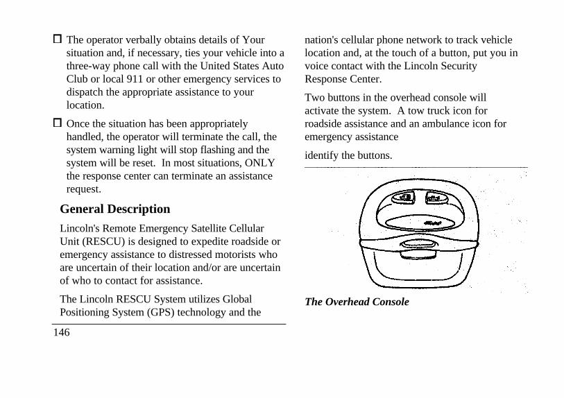
The operator verbally obtains details of Yoursituation and, if necessary, ties your vehicle into athree-way phone call with the United States AutoClub or local 911 or other emergency services todispatch the appropriate assistance to yourlocation.
Once the situation has been appropriatelyhandled, the operator will terminate the call, thesystem warning light will stop flashing and thesystem will be reset. In most situations, ONLYthe response center can terminate an assistancerequest.
General Description
Lincoln's Remote Emergency Satellite CellularUnit (RESCU) is designed to expedite roadside oremergency assistance to distressed motorists whoare uncertain of their location and/or are uncertainof who to contact for assistance.
The Lincoln RESCU System utilizes GlobalPositioning System (GPS) technology and the
146
nation's cellular phone network to track vehiclelocation and, at the touch of a button, put you invoice contact with the Lincoln SecurityResponse Center.
Two buttons in the overhead console willactivate the system. A tow truck icon forroadside assistance and an ambulance icon foremergency assistance
identify the buttons.
The Overhead Console
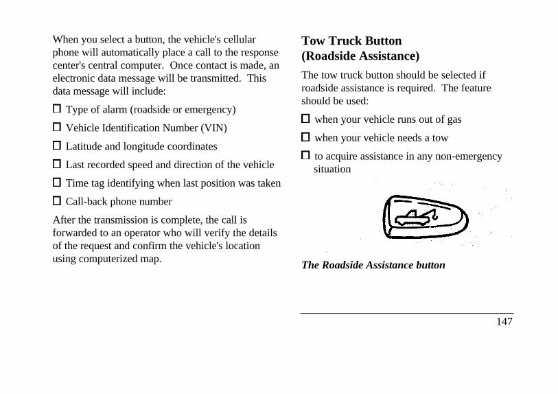
When you select a button, the vehicle's cellularphone will automatically place a call to the responsecenter's central computer. Once contact is made, anelectronic data message will be transmitted. Thisdata message will include:
Type of alarm (roadside or emergency)
Vehicle Identification Number (VIN)
Latitude and longitude coordinates
Last recorded speed and direction of the vehicle
Time tag identifying when last position was taken
Call-back phone number
After the transmission is complete, the call isforwarded to an operator who will verify the detailsof the request and confirm the vehicle's locationusing computerized map.
Tow Truck Button(Roadside Assistance)
The tow truck button should be selected ifroadside assistance is required. The featureshould be used:
when your vehicle runs out of gas
when your vehicle needs a tow
to acquire assistance in any non-emergencysituation
The Roadside Assistance button
147
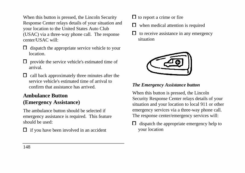
When this button is pressed, the Lincoln SecurityResponse Center relays details of your situation andyour location to the United States Auto Club(USAC) via a three-way phone call. The responsecenter/USAC will:
dispatch the appropriate service vehicle to yourlocation.
provide the service vehicle's estimated time ofarrival.
call back approximately three minutes after theservice vehicle's estimated time of arrival toconfirm that assistance has arrived.
Ambulance Button(Emergency Assistance)
The ambulance button should be selected ifemergency assistance is required. This featureshould be used:
if you have been involved in an accident
148
to report a crime or fire
when medical attention is required
to receive assistance in any emergencysituation
The Emergency Assistance button
When this button is pressed, the LincolnSecurity Response Center relays details of yoursituation and your location to local 911 or otheremergency services via a three-way phone call.The response center/emergency services will:
dispatch the appropriate emergency help toyour location
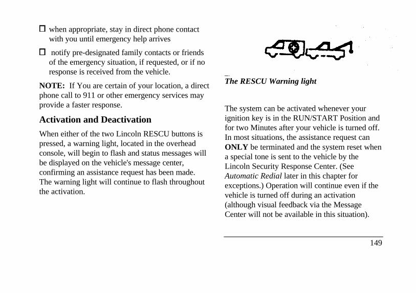
when appropriate, stay in direct phone contactwith you until emergency help arrives
notify pre-designated family contacts or friendsof the emergency situation, if requested, or if noresponse is received from the vehicle.
NOTE: If You are certain of your location, a directphone call to 911 or other emergency services mayprovide a faster response.
Activation and Deactivation
When either of the two Lincoln RESCU buttons ispressed, a warning light, located in the overheadconsole, will begin to flash and status messages willbe displayed on the vehicle's message center,confirming an assistance request has been made.The warning light will continue to flash throughoutthe activation.
The RESCU Warning light
The system can be activated whenever yourignition key is in the RUN/START Position andfor two Minutes after your vehicle is turned off.In most situations, the assistance request canONLY be terminated and the system reset whena special tone is sent to the vehicle by theLincoln Security Response Center. (SeeAutomatic Redial later in this chapter forexceptions.) Operation will continue even if thevehicle is turned off during an activation(although visual feedback via the MessageCenter will not be available in this situation).
149
Cellular Phone Interface
During an activation, Lincoln RESCU takes controlof the vehicle's cellular phone. If the phone is inuse, THE CALL WILL BE TERMINATED and theLincoln Security Response Center will automaticallybe dialed. The cellular handset becomes inoperativeand all voice communication with the operator isaccomplished via the cellular phone's "hands-free"microphone.
NOTE: When an activation is terminated, yourphone is left unlocked, in the "ON" state and maynot return to its previous system selection setting. Itcan be reprogrammed to your previous setting asdesired.
Message Center Interface
During an activation, Lincoln RESCUcommunicates with the vehicle's Message Center.Status messages describing the sequence of stepsbeing executed are displayed, allowing you tovisually follow the activation process. Thefollowing messages are
150
typical of those displayed during an assistancerequest. They are shown in the order in whichthey would appear:
ROADSIDE REQUEST or EMERGNCYREQUEST
CALL IN PROGRESS
RINGING RESPONSE CENTER
SENDING LOCATION DATA
DATA RECEIVED
WAITING FOR OPERATOR
Once an assistance request is made, it willtypically take less than one minute until contactis made with an operator. During voicecommunication the following messages willalternately toggle on the display:
CID XXXXXXXXXX
LAT XXXXXXXXXX
LON
HDG XX
These messages respectively are the customeridentification number, vehicle latitude, vehiclelongitude and heading. Under specialcircumstances, the operator may ask you to read theinformation being displayed on the Message Center.
If vehicle messages are being displayed on theMessage Center (low washer fluid, low oil, doorajar, etc.), they must be cleared in order to view theLINCOLN RESCU messages. To clear the vehiclemessages, press the Message Center RESET button,which is located to the right of the display.Continue pressing the button until all vehiclemessages are cleared.
Automatic Redial
As described previously, when an assistance requestis made, the vehicle's cellular phone automaticallydials the Lincoln Security Response Center's centralcomputer and attempts to send an electronic data
message. Occasionally, it can be difficult for thecomputer to recognize the message if thecellular connection is weak or noisy. If thetransmission of the message is unsuccessful, thedata call will be terminated and the message"REDIAL IN PROGRESS" will be displayed onthe Message Center. A second call willautomatically be placed which bypasses theresponse center's computer and is forwardeddirectly to an operator.
Similarly, if the cellular call is disconnected by thenetwork prior to receipt of the termination tone,another call to the response center will alsoautomatically be dialed. The message "REDIALIN PROGRESS" will be displayed on the MessageCenter and voice communication with an operatorwill be restored.
NOTE: During redial calls, full control of thecellular phone is returned to you. Pressingeither the "PWR" or "END" button on thecellular handset will terminate the assistancerequest and reset the system.
151
Location Data Retransmit Capability
During an activation, the Lincoln Security ResponseCenter operator has the capability to initiate aretransmission of the electronic data message. Thismay be necessary to ensure a more precisedetermination of vehicle location or to track avehicle that is moving. To accomplish theretransmit, a special tone is sent to the vehicle by theresponse center. In this situation you willtemporarily lose voice contact with the operator andthe messages "SENDING LOCATION DATA" and"DATA RECEIVED" will respectively be displayedon the Message Center. After the dataretransmission is complete, voice communicationwill be restored and the CID, LAT, LON and HDGmessage will again alternately toggle on theMessage Center display.
152
Global Positioning System
Vehicle location is continuously updated viaGlobal Positioning System (GPS) technology.GPS was developed by the U.S. Department ofDefense for worldwide navigational andpositioning purposes. It utilizes a constellationof 24 orbiting satellites located more than 20thousand kilometers above the earth. At anygiven time, several of the 24 satellites should bevisible to the vehicle's GPS receiver. Based onthe time for signals emitted by these satellites toreach the receiver, an on-board computer willdetermine the vehicle's location, typically within100 feet. In addition to latitude and longitude,the system also determines heading and speed.
Vehicle positioning information is relayed to theLincoln Security Response Center ONLYduring roadside or emergency requests. Theresponse center will not be able to track yourlocation while in an inactive state.
Lincoln RESCU System Limitations
Service restricted to 48 contiguous states
Your Lincoln RESCU System can be activatedanywhere within the 48 contiguous states. If anactivation occurs outside of this region, the LincolnSecurity Response Center will not be able to assistyou.
Inoperative if cellular phone inactive orinoperative
Lincoln RESCU utilizes your vehicle's cellularphone and will not operate if cellular service has notbeen activated or if the phone is inoperative.
Inoperative if battery discharged or disconnected
Lincoln RESCU is powered by the vehicle's batteryand will not operate if the battery is discharged ordisconnected.
Potentially inoperative if vehicle involved inaccident
If the vehicle is involved in an accident, somecomponents could be damaged, rendering yourLincoln RESCU System inoperative.
Positioning capability degraded if satellitesignals obstructed
Vehicle positioning is accomplished by receiving andinterpreting signals transmitted by satellites. If thesignals are obstructed, positioning capability couldbe degraded or lost. This situation will be mostprevalent in urban areas populated with tallbuildings. Tunnels, underpasses, parking garages,trees, and similar structures could also adverselyaffect positioning performance. Under theseconditions, the system will operate but the responsecenter could have difficulty identifying your currentlocation. (The last valid position obtained before theobstruction is retained, however, and will be sent.)The operator may depend on you to provide verbalinformation regarding vehicle location.
153
Positioning capability temporarily degraded afterbattery reconnect
When your vehicle is started, the Lincoln RESCUGPS receiver begins the process of determiningvehicle location. The receiver will search the skyand attempt to acquire signals from all visiblesatellites. A real-time clock and an almanaccontaining detailed information about the satelliteconstellation are stored in the on-board computer'smemory and are used to expedite the search. If thevehicle's battery is disconnected, the clock memoryis erased and time and date are lost. Once thebattery is reconnected, it could take approximately15 minutes to reacquire the clock and forpositioning capability to be restored. During thistime, the system will operate but the response centerwill not be able to identify your location. In thissituation, the operator will depend on you toprovide verbal information regarding vehiclelocation.
154
Inoperative if cellular signal marginal orunavailable
Since the Lincoln RESCU System utilizes thevehicle's cellular phone, it can only be operatedin geographical areas with cellular coverage.Although approximately 90 percent of the U.S.population lives and works in cellular coverageareas, there are various rural or mountainousareas where coverage is marginal or does notexist. If an activation occurs in this situation,the messages "NO CELLULAR SIGNAL" and"WAITING TO ACQUIRE" will alternately bedisplayed on the Message Center. If afterseveral attempts cellular service cannot beacquired, the message "UNABLE TO PLACECALL" will be displayed, the assistance requestwfll be terminated and the phone will return toits normal operating mode.
Inoperative if cellular system busy
In a particular area, the local cellular system canonly handle a limited number of cellular calls at onetime. Once volume has reached the maximum limit,additional callers are denied access. If an activationoccurs in this situation, the messages "CELLULARSYSTEM BUSY" and "PLEASE WAIT" willalternately be displayed on the message center. Ifafter several attempts a cellular channel cannot beacquired, the message "UNABLE TO PLACECALL" will be displayed, the assistance request willbe terminated and the phone will return to its normaloperating mode.
Incompatible with cellular PIN feature
Some cellular carriers offer custom phone numbersthat are assigned a personal identification number(PIN). In this situation, the user is required to enterthe pin with any phone calls made over the network.The Lincoln RESCU System is not compatible withthe pin feature. At the time your phone is activated,ask your carrier to assign you a
phone number that does not require a personalidentification number entry. If you have difficultyobtaining a non-PIN number, contact your dealeror call the Ford Cellular System Clearinghouse at1-800-367-3357 for assistance.
Incompatible or performance limited withcertain cellular provider features.
Some cellular carriers offer customers variousoptional features with their cellular service.Several of these features are not compatible orcould potentially limit the performance of yourLincoln RESCU System. The cellular featuresthat should be avoided to ensure maximumsystem performance include: no outgoing calls,hotline, call forwarding, no incoming calls, nparestrictions, busy/no answer transfer, and callwaiting. Because carriers are regularly makingnew features available to the customer, this listmay not be complete. Contact your dealer forassistance if you are unsure if a particular cellularfeature is compatible with your Lincoln RESCUSystem.
155
Potential limitations if activated outside homecellular region
At the time you receive your vehicle (or shortlyafter), you will need to select a cellular carrier andactivate your phone. If desired, carrier selection canbe arranged through your dealer. This carrier isusually local to your region and will handle callprocessing and billing services for your cellulartelephone. In order to use your phone whentraveling outside your home cellular region, theservices of the carriers local to the new area will berequired. If your home carrier does not have anagreement with the new local carrier, your phonecalls could be forwarded to an operator and youmay be required to provide a credit card numberbefore your call is processed. If an activation occurscall in this situation, the initial call will be terminatedand a second call which bvpasses the responsecenter’s computer will be placed. UNLIKEDURING THE FIRST CALL ATTEMPT, YOURCELLULAR HANDSET WILL NOT BELOCKED DURING THE SECOND CALL, SOYOU WILL HAVE THE
156
OPTION OF TERMINATING THE ASSISTANCEREQUEST AT ANY TIME BY PUSHING EITHERTHE “PWR" OR THE “END” BUTTON ON THECELLULAR HANDSET. If the second call is notterminated, it will be forwarded to a local cellularcarrier operator. In this situation, you can providethe operator. with the number you are dialing(Lincoln Security Response Center at 1-800-334-1327) and your credit card number or ask to beconnected to the local 911 or other emergencyservices.
Registration Requirement
You are required to register with the LincolnSecurity Response Center shortly after receiving yourvehicle. The registration process is simple and can beaccomplished by calling the Lincoln Security Centerat 1,800-334-1327. Alternatively, the registrationprocess can be completed on-line during anacquaintance period activation. (See “AcquaintanceActivations” later in the section for details.) Theinformation requested will aid in servicing you moreefficiently during the assistance request.
Optional Password Selection/FalseActivations
At the time of your registration, you will be giventhe option of establishing a user password. Allaspects of your service will be identical regardless ofyour password decision except the way falseemergency activations are handled.
If established, the password will be requested by theoperator to confirm an emergency activation wasinitiated in error. If no password or an incorrectpassword is given, the response center's operatorwill seemingly terminate the call but actually stayson the line and sends police to the last calculatedvehicle location (this could be useful in duresssituations). It is very important that you rememberyour password to prevent false dispatches.Similarly, it is also important to provide thepassword to any other individuals who will bedriving the vehicle or who may have need to activatethe system.
If you decide not to establish a password, simplyindicate to the operator that the emergency
assistance request was initiated in error and thecall will be terminated.
In either case, if an activation (roadside oremergency) occurs and the operator cannotestablish voice communication, police assistancewill be dispatched to the vehicle.
NOTE: Information regarding changing orretrieving lost passwords can be obtained bycontacting the Lincoln Security ResponseCenter at 1-800-334-1327.
Acquaintance Activations
It is required that you initiate an acquaintanceactivation shortly after receiving your vehicle andhaving your phone activated. An acquaintanceactivation is initiated by pressing either the roadsideor emergency assistance button. When voicecommunication is established with the LincolnSecurity Response Center, indicate that you are anew user and the operator will follow specialacquaintance period support procedures which are
157
intended to familiarize you with your LincolnRESCU system. As described previously, theacquaintance call can also be used to complete theregistration for new customers.
Service Charges
For four years, beginning with your vehicle'swarranty period, you will be entitled to unlimitedactivations without facing service charges. (Theseactivations should be made only when emergency orroadside assistance is required.) You will beresponsible, however, for any charges imposed byyour cellular phone carrier for the 1-800 phone callto the Lincoln Security Response Center. Afteryour initial service period expires, you may berequired to pay a monitoring service fee. Yourdealer can provide you with specific informationregarding post initial service period fees.
158
Relinquishing your vehicle
At the time you relinquish your vehicle, it isimportant that you contact the Lincoln SecurityResponse Center at 1-800-334-1327 and cancelyour security service. Personal informationprovided to the response center at the time ofyour registration will be removed from thevehicle's file.
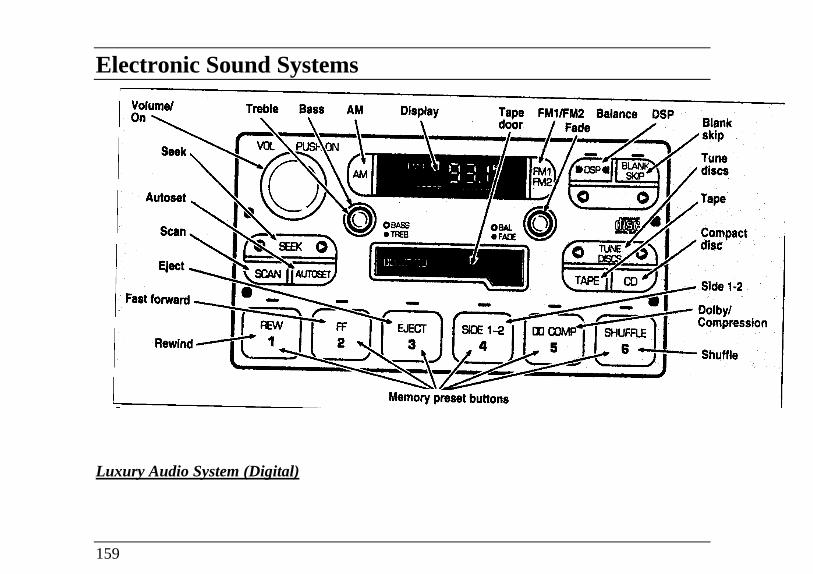
Electronic Sound Systems
Volume on Treble Bass AM Display Tape FM1/FM2 Balance DSP Blank skip
Fade Seek Autoset Scan Eject Fast forward BASS TREB Tune Compact discs Tape Dolby/
Compression Shuffle Rewind Memory preset buttons
Luxury Audio System (Digital)
159
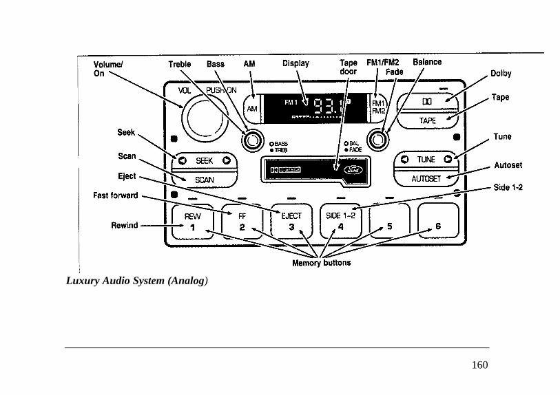
Volume/ Treble Bass AM Display SCAN Dolby Tape Tune Autoset Fastforward
Luxury Audio System (Analog)
160
Luxury Audio SystemUsing the Controls on Your New Radio
How to turn the radio on and off
Press the "VOL/PUSH ON" knob to turn theradio on. Press again to turn it off.
How to adjust the volume
Turn the "VOL/PUSH ON" knob clockwise toincrease the volume and counter-clockwise todecrease the volume.
NOTE: If the volume is set above a certain levelwhen the ignition is turned off, the volume levelwill reset to a "nominal" listening level when theignition switch is turned back on. However, if theradio is turned off with the "VOL/PUSH ON"knob, the volume will not reset and will stay atthe same level when the radio is turned back on.
Selecting the AM or FM frequency band
Push the "AM" or "FM1/FM2" button to selectthe desired frequency band. Pushing the"FM1/FM2" button more than once willalternate between FM1 and FM2. Thesefunctions are used with the station memorybuttons described under How to tune radiostations.
HOW to tune radio stations
There -are four ways for you to tune in aparticular station. You can use the "TUNE","SEEK", 'SCAN”or memory buttons.
Using the "TUNE" function
You can change the frequency up or down oneincrement at a time by Pressing and releasingeither the left ( )or-right ( ) side of the"TUNE" or "TUNE DISCS" button. Tochange frequencies quickly, press and holddown either the right or left side of the button.
161
Manual tuning adjusts your radio to anyallowable broadcast frequency, whether or not astation is present on that frequency. (See AllAbout Radio Frequencies in this section.)
Using the "SEEK" function
Press the right *) side of the 'SEEK" button toselect the next listenable station up thefrequency band. Press the left (.4) side of thebutton to select the next listenable stationdown the frequency band. By holding thebutton down, listenable stations can be passedover to reach the desired station.
Using the 'SCAN" function
Pressing the "SCAN" button will begin thescan mode up the frequency band, stopping oneach listenable station for approximately fiveseconds.
To stop the scan mode on the presentlysampled station, press the "SCAN" button again.
162
Setting the station MEMORY PRESET buttons
Your radio is equipped with 6 stationmemory buttons. These buttons can be usedto select up to 6 preset AM stations and 12FM stations (6 in FMI and 6 in FM2)
1 Select a band, then select a frequency.
2. Press one of the memory buttons and holduntil the sound returns and the lamp abovethe memory button lights up. Thatmemory button is now set.
3. Follow the above steps for each memorypreset button.
NOTE: Custom memory presetscan be recalled using the keyless entrysystem. See Memory Profile System inthe Features chapter.
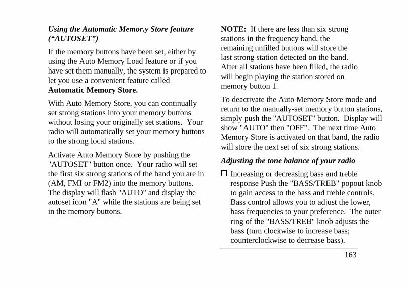
Using the Automatic Memor.y Store feature(“AUTOSET”)
If the memory buttons have been set, either byusing the Auto Memory Load feature or if youhave set them manually, the system is prepared tolet you use a convenient feature calledAutomatic Memory Store.
With Auto Memory Store, you can continuallyset strong stations into your memory buttonswithout losing your originally set stations. Yourradio will automatically set your memory buttonsto the strong local stations.
Activate Auto Memory Store by pushing the"AUTOSET" button once. Your radio will setthe first six strong stations of the band you are in(AM, FMI or FM2) into the memory buttons.The display will flash "AUTO" and display theautoset icon "A" while the stations are being setin the memory buttons.
NOTE: If there are less than six strongstations in the frequency band, theremaining unfilled buttons will store thelast strong station detected on the band.After all stations have been filled, the radiowill begin playing the station stored onmemory button 1.
To deactivate the Auto Memory Store mode andreturn to the manually-set memory button stations,simply push the "AUTOSET" button. Display willshow "AUTO" then "OFF". The next time AutoMemory Store is activated on that band, the radiowill store the next set of six strong stations.
Adjusting the tone balance of your radio
Increasing or decreasing bass and trebleresponse Push the "BASS/TREB" popout knobto gain access to the bass and treble controls.Bass control allows you to adjust the lower,bass frequencies to your preference. The outerring of the "BASS/TREB" knob adjusts thebass (turn clockwise to increase bass;counterclockwise to decrease bass).
163
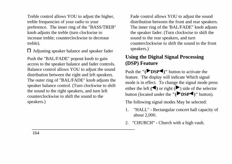
Treble control allows YOU to adjust the higher,treble frequencies of your radio to yourpreference. The inner ring of the "BASS/TREB"knob adjusts the treble (turn clockwise toincrease treble; counterclockwise to decreasetreble).
Adjusting speaker balance and speaker fader
Push the "BAL/FADE" popout knob to gainaccess to the speaker balance and fader controls.Balance control allows YOU to adjust the sounddistribution between the right and left speakers.The outer ring of "BAL/FADE" knob adjusts thespeaker balance control. (Turn clockwise to shiftthe sound to the right speakers, and turn leftcounterclockwise to shift the sound to thespeakers.)
164
Fade control allows YOU to adjust the sounddistribution between the front and rear speakers.The inner ring of the 'BAL/FADE" knob adjuststhe speaker fader. (Turn clockwise to shift thesound to the rear speakers, and turncounterclockwise to shift the sound to the frontspeakers.)
Using the Digital Signal Processing(DSP) Feature
Push the "( DSP )" button to activate thefeature. The display will indicate Which signalmode is in effect. To change the signal mode presseither the left ( ) or right ( ) side of the selectorbutton (located under the "( DSP )" button).
The following signal modes May be selected:
1. "HALL" - Rectangular concert hall capacity ofabout 2,000.
2. "CHURCH” - Church with a high vault.
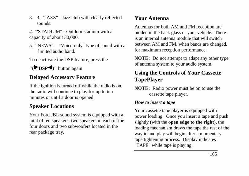
3. 3. "JAZZ" - Jazz club with clearly reflectedsounds.
4. “'STADIUM" - Outdoor stadium with acapacity of about 30,000.
5. “NEWS" - “Voice-only" type of sound with alimited audio band.
To deactivate the DSP feature, press the
"( DSP )" button again.
Delayed Accessory Feature
If the ignition is turned off while the radio is on,the radio will continue to play for up to tenminutes or until a door is opened.
Speaker Locations
Your Ford JBL sound system is equipped with atotal of ten speakers: two speakers in each of thefour doors and two subwoofers located in therear package tray.
Your Antenna
Antennas for both AM and FM reception arehidden in the back glass of your vehicle. Thereis an internal antenna module that will switchbetween AM and FM, when bands are changed,for maximum reception performance.
NOTE: Do not attempt to adapt any other typeof antenna system to your audio system.
Using the Controls of Your CassetteTapePlayer
NOTE: Radio power must be on to use thecassette tape player.
How to insert a tape
Your cassette tape player is equipped withpower loading. Once you insert a tape and pushslightly (with the open edge to the right), theloading mechanism draws the tape the rest of theway in and play will begin after a momentarytape tightening process. Display indicates"TAPE" while tape is playing.
165
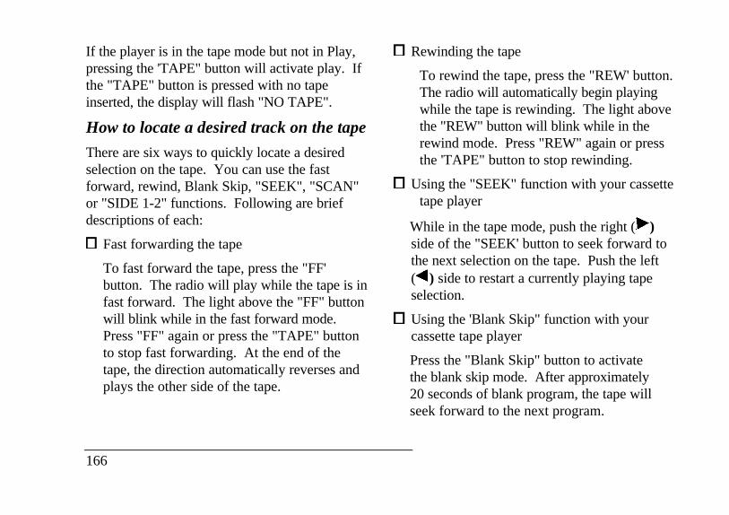
If the player is in the tape mode but not in Play,pressing the 'TAPE" button will activate play. Ifthe "TAPE" button is pressed with no tapeinserted, the display will flash "NO TAPE".
How to locate a desired track on the tape
There are six ways to quickly locate a desiredselection on the tape. You can use the fastforward, rewind, Blank Skip, "SEEK", "SCAN"or "SIDE 1-2" functions. Following are briefdescriptions of each:
Fast forwarding the tape
To fast forward the tape, press the "FF'button. The radio will play while the tape is infast forward. The light above the "FF" buttonwill blink while in the fast forward mode.Press "FF" again or press the "TAPE" buttonto stop fast forwarding. At the end of thetape, the direction automatically reverses andplays the other side of the tape.
166
Rewinding the tape
To rewind the tape, press the "REW' button.The radio will automatically begin playingwhile the tape is rewinding. The light abovethe "REW" button will blink while in therewind mode. Press "REW" again or pressthe 'TAPE" button to stop rewinding.
Using the "SEEK" function with your cassettetape player
While in the tape mode, push the right ( )side of the "SEEK' button to seek forward tothe next selection on the tape. Push the left( ) side to restart a currently playing tapeselection.
Using the 'Blank Skip" function with yourcassette tape player
Press the "Blank Skip" button to activatethe blank skip mode. After approximately20 seconds of blank program, the tape willseek forward to the next program.
Using the "SCAN" function with your cassettetape player
Pushing the "SCAN" button will begin theforward scan mode on the tape currentlyplaying, stopping on each tape selection forapproximately eight seconds.
To stop the scan mode on the presentlysampled tape selection, press the "SCAN"button or the "TAPE" button.
How to change the side of the tape beingplayed
The alternate side of the tape can be selectedby pressing the "SIDE 1-2" button.
How to eject the tape
To stop the tape and eject the cassette, press the"EJECT" button. The tape will eject only whenin the tape mode. The cassette cannot be ejectedwhen the radio is playing an “AM” or "FM"
station. The system will revert to radiomode when the cassette is ejected.
How to store the tape
Press the "AWFM" button to stop thetape player and resume radio play.
Using the Dolby B noisereduction feature
NOTE: Noise reduction systemmanufactured under license from DolbyLabs Licensing Corporation. "Dolby" anddouble-D symbol are trademarks of DolbyLaboratories Licensing Corporation.
Push the button to activate. Whenactivated, the light above the buttonwill be illuminated,
Tape error messages
Your cassette tape player is equipped todiagnose certain problems you mayexperience. Error codes are as follows:
167
TD El - Radio tries to change sides of tape 3times in a 10 second span. push ,EJECT" and tryanother tape. if problem persists, refer problem toqualified personnel for service.
TD E2 - Tape eject failure. Radio tries to ejecttape and it will not eject. push "EJECT" to electtape. if the tape Will not eject, refer problem toqualified personnel for service.
TD E3 - Loading error. push 'EJECT" to electtape. Reload tape. If the same error codeappears in the display, try another tape.
Tips on Caring for the Cassette Playerand Tapes
In order to keep your cassette tape playerperforming the Way it was meant to, read andfollow these simple precautions:
Using a Ford Cassette Cleaning Cartridge toclean the tape player head after 10-12 hours ofplay will help maintain the best playbacksound and proper tape operation.
168
Only cassettes that are go minutes long orless ger than go minutes should be used.Tapes longer than 90 minutes are thinnerand subject to breakage or may jam the tapeplayer mechanism.
Protect cassettes from exposure to directsunlight, high humidity and extreme heat orcold. If they are exposed to extremeconditions allow them to reach a moderatetemperature before playing.
If a tape is. loose inside the cassette; tightenit by putting, your finger or a pencil intoone of the holes and turning the hub untilthe tape is tight.
Loose labels on cassette tapes can becomelodged in the mechanism. Remove anyloose label material before inserting acassette.
Do not leave a tape in the cassette tapeplayer when not in use. High heat in thevehicle can cause the cassette to warp.

Ford 6-CD ChangerIntroduction
The Ford 6-CD Changer is mounted in yourconsole and holds 6 CDs, all controlled by usingbuttons on your Luxury Audio System.
Be sure to read all of the information provided onthe following pages to get the most out of thissystem.
Loading Instructions
1. Open Compact Disc Changer unit by sudingdoor to the right (Figure 1).
Figure 1
2. Push the button to eject the disc"magazine" (holds 6 discs) (Figure 2).
169
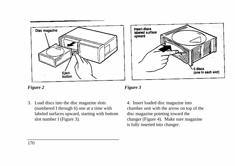
Disc magazine eject button
Figure 2 Figure 3
3. Load discs into the disc magazine slots(numbered I through 6) one at a time withlabeled surfaces upward, starting with bottomslot number I (Figure 3).
170
4. Insert loaded disc magazine intochamber unit with the arrow on top of thedisc magazine pointing toward thechanger (Figure 4). Make sure magazineis fully inserted into changer.
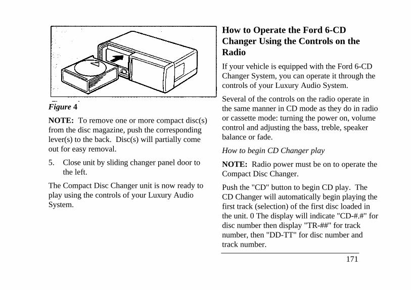
Figure 4
NOTE: To remove one or more compact disc(s)from the disc magazine, push the correspondinglever(s) to the back. Disc(s) will partially comeout for easy removal.
5. Close unit by sliding changer panel door tothe left.
The Compact Disc Changer unit is now ready toplay using the controls of your Luxury AudioSystem.
How to Operate the Ford 6-CDChanger Using the Controls on theRadio
If your vehicle is equipped with the Ford 6-CDChanger System, you can operate it through thecontrols of your Luxury Audio System.
Several of the controls on the radio operate inthe same manner in CD mode as they do in radioor cassette mode: turning the power on, volumecontrol and adjusting the bass, treble, speakerbalance or fade.
How to begin CD Changer play
NOTE: Radio power must be on to operate theCompact Disc Changer.
Push the "CD" button to begin CD play. TheCD Changer will automatically begin playing thefirst track (selection) of the first disc loaded inthe unit. 0 The display will indicate "CD-#.#" fordisc number then display "TR-##" for tracknumber, then "DD-TT" for disc number andtrack number.
171
How to change the disc being played
When in the CD mode, you can change discs bypressing the right (pop.) side of the "TUNEDISCS" button (to select the next disc) or theleft ( ) side of the "TUNE DISCS" button (toselect the next disc) or the left ( ) side of the“TUNE DISCS” button to select the previousdisc). Play will begin on the first track of theselected disc.
When either side of the button is pressed andheld, the CD changer will continue fast-forwarding or reversing through the discs in thedisc magazine. During these functions, thedisplay will indicate the disc number.
How to change the track being played
Press the right ( ) side of the "SEEK" button toseek forward to the next track of current disc.After the last track has been completed, the CDplayer automatically wraps back to the first trackof the current disc.
172
Press the left ( ) side of the SEEKbutton to seek in reverse to the previoustrack on the current disc. If a selectionhas been playing for three seconds ormore and you press the left ( ) side ofthe SEEK button, the CD Changer willreplay that selection from the beginning.
Operating the CD Compression featureThe compression feature will bring softand loud passages closer together for amore consistent listening level.
To turn the compression on, press the #5" /COMP" button. (While in the CDChanger mode, the Dolby button controlsthe compression function.) When thecompression feature is activated, thedisplay will indicate "C". Press again todeactivate.
Operating the Shuffle feature
The shuffle feature on your CD player allows youto listen to your disc selections in a differentorder. When this feature is activated, your CDplayer will randomly select and play tracks on thedisc.
Press the "SHUFFLE" button to turn on, press itagain to turn off. When on, the light above the"SHUFFLE" button will illuminate.
Operating the "SC4N"function
Press the "SCAN" button to enter the scan mode.The CD player will begin scanning the disc,stopping on each listenable track forapproximately an eight second sampling. Thiscontinues until you press the "SCAN" button asecond time.
Operating the Shuffle and Scan featuressimultaneously
Both the shuffle and scan features can beactivated simultaneously. In this mode, theplayer will randomly pick a selection and playthe first eight seconds. This process iscontinued until either the "SCAN" button or"SHUFFLE" button is pressed a second time.
How to stop CD play
While in CD Changer mode, press the EJCT,AM or FMI/FM2 button to stop CD play andresume radio play. Also, loading a cassette intothe cassette deck will stop CD play and begincassette play.
Balance control allows you to adjust the sounddistribution between the right and left speakers.Push the "AUDIO" button repeatedly until thedisplay reads "BAL." Push the right (+) side ofthe "VOLUME" button to shift the sound to theright speakers, and push the left (-) side to shiftthe sound to the left speakers.
173
How to take care of and clean the CD Changer anddiscs
To ensure the continued performance of your CDChanger carefully read the following precautions:
Always handle a disc by the edge. Nevertouch the playing surface.
Before playing, inspect all discs for anycontamination. If needed, clean discs with anapproved disc cleaner, such as theDiscwasher Compact Disc Cleaner or theAllsop 3 Compact Disc Cleaner, by wipingfrom the center out to the edges. Do not usea circular motion to clean.
Do not clean discs with solvents such asbenzine, thinner, commercially availablecleaners or antistatic spray intended for analogrecords.
Do not expose the discs to direct sunlight orheat sources for an extended period of time.
174
Do not insert more than one disc intoeach disc slot of the disc magazine.Doing so may damage the discs, discmagazine or the disc changer.
Do not insert anything other than discsinto the disc magazine.
/!\ WARNING
The laser beam used in the compact discplayer is harmful to the eyes. Do notattempt to disassemble the case.
CD Error Messages
Your system is equipped to diagnosecertain problems you may experience.The error codes are:
- CD El - Mechanism error.
- CD E2 - Focus error.
- BAD CD - Disc unreadable.
- TOO HOT - Mechanism over 167' Farenheit,allow to cool before playing.
- NO CD - Empty slot or magazine.
- NO DJ - CD Changer not connected or notcommunicating.
Common Operating Conditions of theCD Player
The following information is designed to helpyou recognize typical situations that could bemistakenly interpreted as mechanicalmalfunctions of the disc player.
A disc is already loaded.
The disc is inserted with the label surfacedownward.
The disc is dusty or defective.
The player's internal temperature is above167°F (75°C). Allow the player to cool offbefore operating.
Different manufacturers of compactdiscs may produce discs with differentdimensions or tolerances, some ofwhich may not be within industrystandards or in accordance with theCD format. Because of this, a newdisc that is free of dust and scratchescould be defective and may not play onyour Ford Compact Disc Player.
If play does not begin after the CD buttonis pushed:
The radio is not on.
The unit is in the stop mode.
Moisture may have condensed on thelenses within the unit. If this occurs,remove the disc and waitapproximately an hour until themoisture evaporates.
175
If the sound skips:
Badly scratched discs or extremely roughroads will cause the sound to skip. Skippingwill not damage the disc player or scratch thediscs.
Common Radio ReceptionConditionsSeveral conditions prevent FM reception frombeing completely clear and noise-free, such as thefollowing:
Distance/Strength
The strength of the FM signal is directly relatedto the distance the signal must travel. Thelistenable range of an average FM signal isapproximately 24 miles (40 km). Beyond thisdistance, the radio is operating in a "fringe" areaand the signal becomes weaker. Also, "SignalModulation" is used by some stations to increasetheir "loudness" relative to other stations. Thedifference in loudness can be a result of signalmodulation as well as signal strength.
176
Terrain
The terrain (hilly, mountainous, tall buildings) ofthe area over which the signal travels mayprevent the FM signal from being noise-free.
Repeated pops and hisses which are heard duringan otherwise clear broadcast can occur near thestation because of the "line of sight"characteristic of FM radio waves.
If there is a building or large structure betweenthe antenna and station, some of the signal"bends" around the building, but certain spotsreceive almost no signal. Moving out of the"shadow" of the structure will allow the stationto return to normal.
When the radio waves are reflected offobjects or structures, the reflected signalcancels the normal signal, causing theantenna to pick up noise and distortion.Cancellation effects are most prominent inmetropolitan areas, but also can becomequite severe in hilly terrain and depressedroadways.
To minimize these conditions, a stereo/monoblend circuit has been incorporated into thissystem. This feature automatically switches aweak stereo signal to a clearer monaural signal,which improves the quality of reception.
Several sources of static are normal conditionson AM frequencies. These can be caused bypower lines, electric fences, traffic lights andthunderstorms.
Another reception phenomenon is Strong SignalCapture and Overload. This can occur whenlistening to a weak station and when passinganother broadcast tower. The close station maycapture the more distant station, although thedisplayed frequency does not change. Whilepassing the tower, the station may switch backand forth a few times before returning to theoriginal station.
When several broadcast towers are present(common in metropolitan areas) severalstations may overload the receiver,resulting in considerable station changing,mixing and distortion.
Automatic gain control circuitry for both AM andFM bands has been incorporated into this system toreduce strong signal capture and overload.
All About Radio Frequencies
The Federal Communications Commission (FCC)and the Canadian Radio TelecommunicationsCommission (CRTC) establish the frequencies thatAM and FM radio stations may use for theirbroadcasts. The allowable frequencies are, AM:530, 540... 1600, 1610 kHz in 10 kHz steps; FM:87.9, 88.1... 107.7, 107.9 MHz in 0.2 MHz steps.
Not all frequencies will be assigned to a given area.This radio will time to each of these frequenciesusing manual tune and no fine tuning is necessary asradio stations may not use other frequencies.
177
Some FM radio stations advertise a "rounded-off" frequency which is not the frequency theyactually broadcast on. For example, a radiostation that is assigned a frequency of 98.7 MHzmay call itself "Radio 99" even though 99.0MHz is not an allowable FM broadcastfrequency.
178
Important Warranty andService InformationAbout Your Warranty
Your sound system is warranted for fouryears or 50,000 miles (whichever occursfirst). Consult your vehicle warranty bookletfor further information.
Servicing Your Audio System
At Ford Electronics, we stand behind ouraudio systems with a comprehensive serviceand repair program. If anything should gowrong with your Ford audio system, return toyour dealer for service. There is a nationwidenetwork of qualified Ford authorized repaircenters to assist you.
Driving Your ContinentalYour vehicle has an automatic overdrivetransaxle. You may be familiar with the term"transmission." We use transaxle because it is amore accurate term for vehicles that have front-wheel drive.
Driving with an AutomaticOverdrive TransaxleYour automatic overdrive transaxle providesfully automatic operation in either (Overdrive) or D (Drive). Driving with the shiftselector in (Overdrive) gives the best fueleconomy for normal driving conditions. Formanual control, start in 1 (First) and then shiftmanually.
Your vehicle is equipped with an ElectronicPowertrain Control Module that limits engineand/or vehicle speeds with a cut-out mode topromote durability.
Putting Your Vehicle in Gear
Your vehicle's gearshift can be on the columnor on the console.
/!\ WARNING
Hold the brake pedal down while youmove the gearshift lever from position toposition. If you do not hold the brakepedal down, your vehicle may moveunexpectedly and injure someone.
179
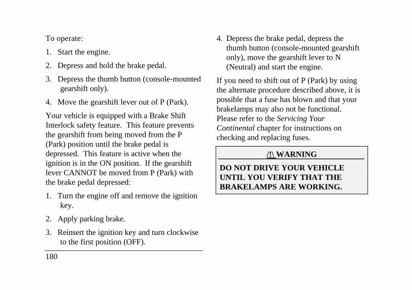
To operate:
1. Start the engine.
2. Depress and hold the brake pedal.
3. Depress the thumb button (console-mountedgearshift only).
4. Move the gearshift lever out of P (Park).
Your vehicle is equipped with a Brake ShiftInterlock safety feature. This feature preventsthe gearshift from being moved from the P(Park) position until the brake pedal isdepressed. This feature is active when theignition is in the ON position. If the gearshiftlever CANNOT be moved from P (Park) withthe brake pedal depressed:
1. Turn the engine off and remove the ignitionkey.
2. Apply parking brake.
3. Reinsert the ignition key and turn clockwiseto the first position (OFF).
180
4. Depress the brake pedal, depress thethumb button (console-mounted gearshiftonly), move the gearshift lever to N(Neutral) and start the engine.
If you need to shift out of P (Park) by usingthe alternate procedure described above, it ispossible that a fuse has blown and that yourbrakelamps may also not be functional.Please refer to the Servicing YourContinental chapter for instructions onchecking and replacing fuses.
/!\ WARNING
DO NOT DRIVE YOUR VEHICLEUNTIL YOU VERIFY THAT THEBRAKELAMPS ARE WORKING.
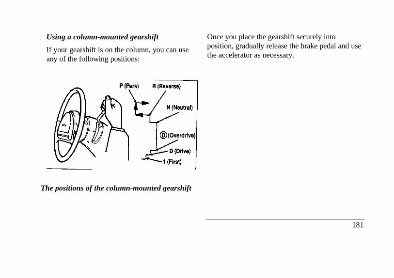
Using a column-mounted gearshift
If your gearshift is on the column, you can useany of the following positions:
Park neutral reverst overdrive drive first
The positions of the column-mounted gearshift
Once you place the gearshift securely intoposition, gradually release the brake pedal and usethe accelerator as necessary.
181
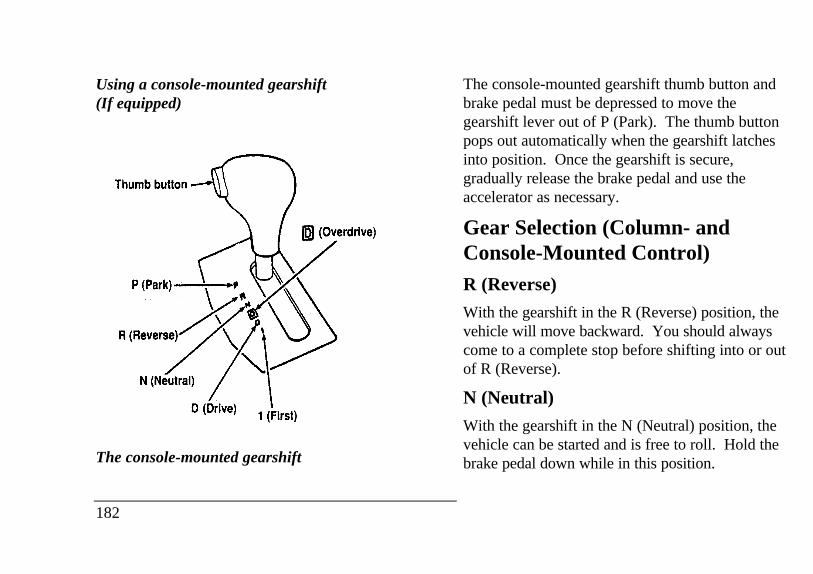
Using a console-mounted gearshift(If equipped)Thumb button Park Reverse Neutral Drive First
The console-mounted gearshift
182
The console-mounted gearshift thumb button andbrake pedal must be depressed to move thegearshift lever out of P (Park). The thumb buttonpops out automatically when the gearshift latchesinto position. Once the gearshift is secure,gradually release the brake pedal and use theaccelerator as necessary.
Gear Selection (Column- andConsole-Mounted Control)R (Reverse)
With the gearshift in the R (Reverse) position, thevehicle will move backward. You should alwayscome to a complete stop before shifting into or outof R (Reverse).
N (Neutral)
With the gearshift in the N (Neutral) position, thevehicle can be started and is free to roll. Hold thebrake pedal down while in this position.
Driving
When to use (Overdrive)
(Overdrive) is the usual driving position for anautomatic overdrive transaxle. It works the sameway D (Drive) works, automatically upshifting ordownshifting as the vehicle speeds or slows.
However, (Overdrive) also shifts into a fourth gear- an overdrive gear - when your vehicle cruises at aconsistent speed for any length of time. This fourthgear will increase your fuel economy when you travelat cruising speeds.
(Overdrive) may not be appropriate for certainterrain. If the transaxle shifts back and forth betweenthird and fourth gears while you are driving on hillyroads or if your vehicle requires additional power forclimbing hills, shift to D (Drive).
When to use D (Drive)
D (Drive) eliminates the excessive shiftingbetween third and fourth gears that yourvehicle sometimes does when you are travelingthrough hilly terrain in Overdrive. It alsogives more engine braking to ml slow yourvehicle on downgrades than Overdrive.
When to use 1 (First)
Use I (First) when added engine braking isdesired when descending steep hills.
The automatic transaxle will shift to the propergear to ascend any grade without any need toshift to I (First).
P (Park)
Always come to a complete stop before youshift into P (Park). Make sure that thegearshift is securely latched in P (Park). Thislocks the transaxle and prevents the frontwheels from rotating.
183
/!\ WARNING
Always set the parking brake fully and makesure that the gearshift is securely latched in P(Park). Never leave your vehicle unattendedwhile it is running.
You can tell a column-mounted gearshift is securelylatched in P (Park) if the lever is adjacent to the P(Park) and you cannot move it without pulling ittoward you and rotating it downward.
You can tell a console-mounted gearshift is securelylatched in P (Park) if the lever is adjacent to the P(Park) and you cannot move it without pushing in thethumb button.
The gearshift will lock when you turn the key to theLOCK position. When the gearshift is in anyposition except P (Park), the ignition key cannot beturned to the LOCK position or removed from thesteering column. To remove the key, the gearshiftlever must be in P (Park).
184
Traction Control (If equipped)Your vehicle may be equipped with theoptional Traction Control, system. Thissystem helps prevent wheel spin in order toimprove tire traction and is an especially usefulfeature when you drive in hilly areas or onslippery, icy or snowy roads.
When the Traction Control system iscontrolling wheelspin, an electric motor soundmay be heard from the engine compartment andengine acceleration may seem slower. This isnormal.
Traction Control works automatically byrapidly applying and releasing the brakes andreducing engine torque to prevent one or bothof the front drive wheels from spinning duringacceleration.
During the Traction Control function, whichmost often occurs during low speedacceleration on slippery surfaces, a noise maybe heard coming from the engine compartment.This is normal and may last for a few secondsduring the acceleration of the vehicle.
In general, this system improves your vehicle'sstability and acceleration performance when roadconditions warrant. Traction Control is fullyeffective at all vehicle speeds.
If the Traction Control system is cycledexcessively, the brake portion of the system will shutdown to prevent the front brakes from overheating.A limited Traction Control function using enginetorque will still control wheels from spinning. Acooling down period is required to prevent damageto the brakes. This time period varies and dependson brake usage during the cooling down period.Anti-Lock braking is not affected and will functionnormally during the cool down period.
After the cool down period, the full TractionControl' function is restored.
Steering Your VehicleYour vehicle comes with power steering.Power steering uses energy from the engine tohelp steer your vehicle.
If the amount of effort needed to steer yourvehicle changes, check your steering effortselection in the Message Center. If this is notthe problem, have the power steering systemchecked. If the power steering system breaksdown (or if the engine is turned off), you cansteer the vehicle manually but it takes moreeffort.
The steering system in your vehicle is speedsensitive. This means that the steering effort islight for parking and heavier for highwaydriving. However, if you have to swervearound an object or another vehicle, yoursteering will have full power assist.
185
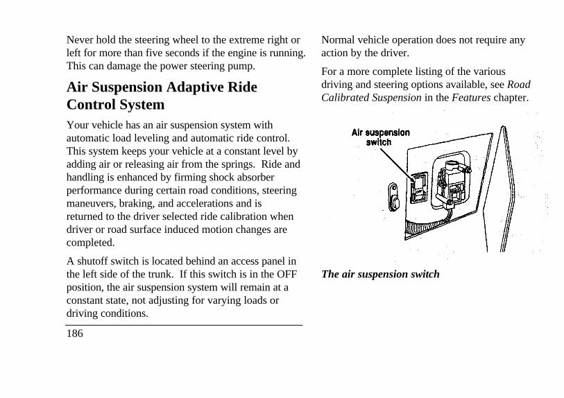
Never hold the steering wheel to the extreme right orleft for more than five seconds if the engine is running.This can damage the power steering pump.
Air Suspension Adaptive RideControl SystemYour vehicle has an air suspension system withautomatic load leveling and automatic ride control.This system keeps your vehicle at a constant level byadding air or releasing air from the springs. Ride andhandling is enhanced by firming shock absorberperformance during certain road conditions, steeringmaneuvers, braking, and accelerations and isreturned to the driver selected ride calibration whendriver or road surface induced motion changes arecompleted.
A shutoff switch is located behind an access panel inthe left side of the trunk. If this switch is in the OFFposition, the air suspension system will remain at aconstant state, not adjusting for varying loads ordriving conditions.
186
Normal vehicle operation does not require anyaction by the driver.
For a more complete listing of the variousdriving and steering options available, see RoadCalibrated Suspension in the Features chapter.
Air suspension switch
The air suspension switch
BrakesApplying the Brakes
Your vehicle has anti-lock disc brakes on all fourwheels. They adjust automatically as the brake padswear down.
When you press down hard on the brake pedal, thewheels will not lock and slide. The Anti-lock BrakeSystem (ABS) automatically starts releasing andreapplying the front brakes independently and therear brakes together whenever your wheels start tolock. When this happens, you will feel the brakepedal pulsate. This is an indication that the ABSsystem is working correctly and is normal.
Each time you turn the ignition key to the ONposition, the anti-lock brake system will functionthrough one test cycle. When this happens, the ANTI-LOCK light will come on for up to five seconds and aclunk may be felt in the pedal. If the light stays onlonger than five seconds, shut off the
engine and restart. If it remains on, it means theanti-lock brake system is disabled and should beserviced immediately to restore the benefits ofthe anti-lock feature. Normal braking is notaffected unless the brake warning light is also lit.
The And-lock Brake System has self-checkcapabilities. As described above, the systemturns on the ANTI-LOCK light each time youstart your engine. After the engine is startedand the ANTI-LOCK light turns off, the systemperforms another test the first time the vehiclereaches 14 m.p.h. (22 km/h). The system turnson the ABS pump motor for approximately 1/2second. At this time, a mechanical noise maybe heard. This is a normal part of the self-check feature. If a malfunction is found duringthis check the ANTI-LOCK light will come on.
Do not drive with your foot resting on thebrake pedal; you will wear out the linings andincrease your vehicle's stopping distance.Brake rotor damage may also eventually occur.
187
NOTE: If you are driving down a long or steep hill,shift to a lower gear and do not apply your brakescontinuously. If you apply your brakes continuously,they may overheat and become less effective.
Occasional brake squeal during light to moderatestops does not affect the function of the brake systemand is normal. However, if the squeal becomeslouder or more frequent, have your brakes inspectedby your dealer or a qualified service technician.
Ford Motor Company has not found any detrimentaleffects of popular mobile radio transmittingequipment installed on vehicles with the anti-lockbrake system, if the equipment is installed accordingto the manufacturer's instructions. However, ifmobile radio transmitting
188
equipment is installed in your vehicle and, ifeither the anti-lock brake system cycles or theANTI-LOCK light comes on at any time otherthan right after you turn the key to the ONposition or during a sudden stop, have yourmobile radio dealer inspect the installation.
Parking BrakeThe parking brake should be used wheneveryou park your vehicle.
The parking brake is suspended just below thelower left corner of the instrument panel.
To set the parking brake while parking yourvehicle, apply the brake pedal with your rightfoot and hold it while you push the parkingbrake down firmly and fully with your left foot.
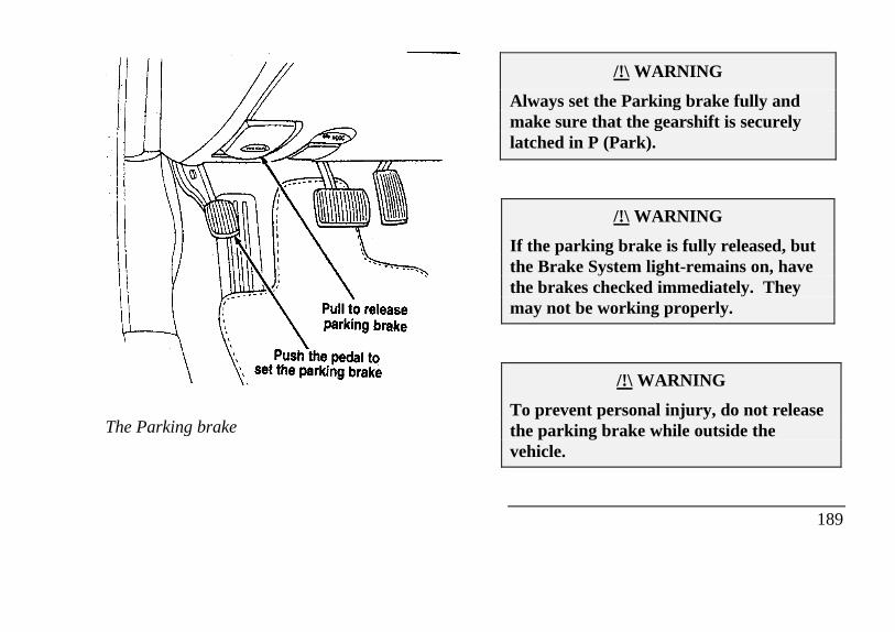
The Parking brake
/!\ WARNING
Always set the Parking brake fully andmake sure that the gearshift is securelylatched in P (Park).
/!\ WARNING
If the parking brake is fully released, butthe Brake System light-remains on, havethe brakes checked immediately. Theymay not be working properly.
/!\ WARNING
To prevent personal injury, do not releasethe parking brake while outside thevehicle.
189
You have an automatic release for the parking brake.The parking brake should automatically unlock whenyou move the gearshift to any forward gear while theengine is running. However, the automatic releasedoes not work when the gearshift is in reverse,neutral or park.
To manually release the parking brake, pull theBRAKE RELEASE handle located on the lower leftcomer of the instrument panel. The Brake WarningLight will illuminate if the parking brake is not fullyreleased when the engine is running.
The parking brake is not designed to stop a movingvehicle, but you can use the parking brake to stopyour vehicle in an emergency if the normal brakesfail. However, since the parking brake applies onlythe rear brakes, the stopping distance will increasegreatly and the handling of your vehicle will beadversely affected.
190
Always check the Brake Warning light eachtime you start your engine. Driving with theparking brake on will cause the brakes to wearout quickly and will reduce the fuel economy.
Driving Under Special ConditionsTips for Safe Driving
As with any new vehicle, yours may drive andhandle differently from your previous vehicle.Use care until you become accustomed to itsvarious features and driving characteristics.
Operate your vehicle within reasonable limits.Sudden acceleration, deceleration, turning, orcombinations of these maneuvers can cause avehicle to behave differently than anticipated.
Driving in Bad Weather
Slippery roads
On some slippery road surfaces, front-wheel drivemay provide better acceleration than rear-wheeldrive. However, this does not mean that yourvehicle can stop any faster or any better than avehicle with rear-wheel drive. Exercise the samecaution while driving on slippery roads with yourfront-wheel drive vehicle as you would with a rear-wheel drive vehicle.
Do not quickly move the steering wheel unlessnecessary.
Drive slower than you normally would.
Give your vehicle more distance to stop.
/!\ WARNING
To avoid skidding and losing control onslippery roads, do not downshift into First(1) when you are moving faster than 20mph (32 km/h).
/!\ WARNING
If your vehicle has speed control, do notuse it on slippery roads. You could losecontrol of your vehicle and could injuresomeone.
If your vehicle gets stuck (for example, in mudor snow), you may try to "rock" it out of thespot. Shift, in a steady rhythm, betweenforward and reverse gears. While in each gear,press lightly on the accelerator and release.
191
/!\ WARNING
Do not spin the wheels at over 35 mph (55km/h). The tires may fail and injure apassenger or bystander.
By moving the vehicle backward and forward, youmay gain enough momentum to move out of thespot. Do not rock the vehicle for more than a fewminutes. This may overheat the engine, damage thetransaxle, or damage the tires. If you are still stuckafter a minute or two of rocking, call for a tow truck.
High water
Do not drive through flooded areas unless you aresure that the water is below the bottom of the wheelrims.
If you must drive through high water, drive slowly.You may have limited traction or wet brakes, soallow extra stopping distance because your vehiclewill not stop as quickly as usual.
192
After you drive through the standing water,apply your brakes gently several times as yourvehicle moves slowly. This helps to dry thebrakes.
Driving With a Heavy LoadThere are limits to the amount of weight yourvehicle can carry or tow. The total weight ofyour vehicle, plus the weight of the passengersand cargo, should never be more than theGross Vehicle Weight Rating (GVWR). Also,the weight that your vehicle carries over thefront axle and rear axle should never be morethan the Gross Axle Weight Rating (GAWR)for the respective axle.
You can find your vehicle's GVWR andGAWR on the Safety Compliance CertificationLabel on the left front door lock facing or onthe door latch post pillar.
The weight limits of your vehicles tires affect theGVWR or GAWR limitations. Usage of replacementtires with higher weight limit than originals does notincrease GVWR or GAWR. Usage of lowercapacity replacement tires may lower GVWR andGAWR limitations.
/!\ WARNING
If the GVWR or the GAWR specified on theSafety Compliance Certification Label isexceeded, your vehicle may be damaged oryou may lose control and injure someone.
Limiting Your Vehicle's Load
The load that you add to Your vehicle must notexceed the maximum load stated on the SafetyCompliance Certification Decal attached to the leftfront door pillar.
To figure the weight of your vehicle's load, addthe weights of.
the driver and passengers
luggage and any other items that you put inyour vehicle
the tongue load of the loaded trailer
the Weight of any equipment that has beenadded to your vehicle since it was deliveredto your dealer
If you do not know the actual weights of theseitems, use the following procedure to figure theweight of a load:
1. Weigh your vehicle without the driver,passengers and luggage. You might takeyour vehicle to a shipping company or aninspection station for trucks.
2. Then weigh Your vehicle with the driverpassengers and luggage.
193
3. Subtract the first reading from the second tofigure the total weight of the load.
After determining this load, you must also make surethat the total weight of your vehicle, plus the load itcarries, is less than its GVWR. Also, make sure thatthe weight your vehicle carries over each axle is lessthan the GAWR for the respective axle.
If your vehicle exceeds the GVWR, remove cargofrom your vehicle accordingly. If your vehicleexceeds the GAWR for either axle, shift the load orremove cargo accordingly.
/!\ WARNING
Improper distribution of your vehicle's loador carrying weight in excess of the amountshown on the tire decal can cause rapid tirewear or loss of vehicle control.
194
Trailer TowingYour vehicle is capable of towing a trailer of upto a maximum of 2,000 lbs. (907 kg) grosstrailer weight with a maximum tongue load of200 lbs. (91 kg).
Because towing a trailer puts extra strain onyour vehicle, you must follow certainprecautions for your safety and the good ofyour vehicle:
Stay within the load limits for towing yourvehicle. (See Trailer towing specificationsin this chapter.)
Carefully and thoroughly prepare yourvehicle for towing, making sure to use theright equipment and to attach it properly.(See Preparing to Tow in this chapter.)
Use extra caution when driving your vehiclewhile you tow. (See Driving while you towin this chapter.)
Service your vehicle more frequently if you tow atrailer. (See Servicing your vehicle if you tow inthis chapter.)
Ten to 15% of the loaded trailer's weight should beon the tongue. However, the tongue load shouldnever exceed 10% of the maximum weight that yourvehicle can safely tow.
New vehicles should be driven 2,000 miles (3,200km) before towing a trailer.
/!\ WARNING
Towing trailers beyond the maximumrecommended gross trailer weight exceeds thelimit of the vehicle and could result in enginedamage, transaxle damage, structuraldamage, loss of control, and personal injury.
/!\ WARNING
Do not tow a trailer when thetemporary spare tire is being used.
See the following chart for the amount ofweight your vehicle can tow.
195
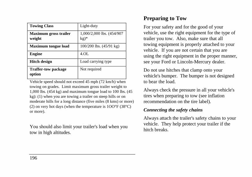
Towing Class Light-duty
Maximum gross trailerweight
1,000/2,000 lbs. (454/907kg)*
Maximum tongue load 100/200 lbs. (45/91 kg)
Engine 4.OL
Hitch design Load carrying type
Traffer-tow packageoption
Not required
Vehicle speed should not exceed 45 mph (72 km/h) whentowing on grades. Limit maximum gross trailer weight to1,000 lbs. (454 kg) and maximum tongue load to 100 lbs. (45kg): (1) when you are towing a trailer on steep hills or onmoderate hills for a long distance (five miles (8 kms) or more)(2) on very hot days (when the temperature is 1OO°F (38°C)or more).
You should also limit your trailer's load when youtow in high altitudes.
196
Preparing to Tow
For your safety and for the good of yourvehicle, use the right equipment for the type oftrailer you tow. Also, make sure that alltowing equipment is properly attached to yourvehicle. If you are not certain that you areusing the right equipment in the proper manner,see your Ford or Lincoln-Mercury dealer.
Do not use hitches that clamp onto yourvehicle's bumper. The bumper is not designedto bear the load.
Always check the pressure in all your vehicle'stires when preparing to tow (see inflationrecommendation on the tire label).
Connecting the safety chains
Always attach the trailer's safety chains to yourvehicle. They help protect your trailer if thehitch breaks.
To connect the trailer's safety chains:
1. Cross the chains under the trailer tongue andattach them to your vehicle's frame or hookretainers. Never attach the safety chains to yourvehicle's bumper. The bumper is not designed tobear the weight of a trailer.
2. Make sure that you leave enough slack in thechains to allow you to turn corners.
If you use a rental trailer, follow the instructions thatthe rental agency gives you.
Connecting the trailer's brakes
Electric brakes and manual, automatic, or surge-typehydraulic brakes are safe if you install them properlyand adjust them according to the manufacturer'sinstructions. Be sure that your trailer's brakes meetlocal and federal regulations.
Separate trailer brakes of adequate size should beused for trailers weighing over 1.000 lbs. (454 kg)loaded weight.
/!\ WARNING
Do not connect a trailer's hydraulicbrake system directly to your vehicle'sbrake system. Your vehicle may nothave enough braking power and yourchances of having a collision greatlyincrease.
Connecting the trailer's lights
Do not connect a trailer's fighting systemwiring directly to your vehicle's fightingsystem wiring. To get the proper equipmentfor hooking up your trailer's lights, see yourlocal trailer dealer and your Ford dealer. Besure to follow their instructions carefully.
If you do not install trailer lights correctly, youmay cause damage to the vehicle's hghtingsystem.
197
Driving While You Tow
Be especially careful when driving while you tow atrailer. Never drive faster than 45 mph (70 km/h)when you tow in hilly country on hot days. Also,anticipate stops so that you can brake gradually.
Towing a trailer increases the load on the engine andtransaxle, particularly in hilly country and withheavier trailers. Under these conditions you mayexperience an excessive amount of shifting betweenOverdrive and Third gears. Moving the shift selectorto D (Overdrive Lockout) will keep this fromhappening and will provide better engine braking.When driving in less hilly country or with a lightertrailer load. you may move the gearshift selectorlever to (Overdrive) without experiencingexcessive shifting.
198
When driving down steep hills, you should putthe gearshift selector lever in the I (First)position to shift the transaxle into second gear.This will provide additional engine braking.The automatic transaxle will automaticallydownshift to the proper gear for driving up agrade.
If you use the speed control while you aretowing on very long, steep grades, the speedcontrol may shut off.
Servicing your vehicle if you tow
If you tow a trailer for a long distance, yourvehicle will need to be serviced more frequentlythan usual. See the Maintenance Schedule andRecord booklet.
Roadside EmergenciesJump-Starting Your Vehicle
Your vehicle's battery may die if you leave the lightson or any electrical equipment on after you turn theengine off. If this happens, you may be able tojump-start from a booster battery to start yourvehicle.
/!\ WARNING
The gases around the battery can explode ifexposed to flames, sparks, or lit cigarettes.An explosion could result in injury or vehicledamage.
/!\ WARNING
To protect yourself when charging a battery,always shield your face and eyes. Make surethat you can breathe fresh air.
/!\ WARNING
Applying too much pressure on the ends whenlifting a battery could cause acid to spill. Liftthe battery with a carrier or with your handson the opposite comers.
199
/!\ WARNING
Batteries contain sulfuric acid which bumsskin, eyes, and clothing.
If the acid touches someone's skin, eyes, or clothing,immediately flush the area with water for at least 15minutes. If someone swallows the acid, have him orher drink lots of milk or water first, then Milk ofMagnesia, a beaten egg, or vegetable oil. Call adoctor immediately.
To avoid damaging your vehicle or your battery, andto avoid injury to yourself, follow these directionsfor preparing your vehicle to jump-start andconnecting the jumper cables in the order they aregiven. If in doubt, call for road service.
200
Preparing Your Vehicle
1 . Your vehicle has a 12-volt starting system, soyou need to use a 12-volt jumper system. Youwill damage your starting motor, ignition system,and other electrical parts if you connect them to a24-volt power supply (either two 12-voltbatteries in series,or a 24-volt generator set).
2. Do not disconnect the battery of the disabledvehicle. You could damage the vehicle'selectrical system.
3. Park the booster vehicle close to the hood of thedisabled vehicle. Make sure the vehicles do nottouch each other. Set the parking brake on bothvehicles and stay clear of the engine cooling fanand other moving parts.
4. Check all battery terminals and remove anyexcessive corrosion before you attach the jumpercables.
5. Turn on the heater fan in both vehicles. Press theDEFROST button. Turn off all other switchesand gauges.
Connecting the jumper cables
1. Connect one end of the first jumper cable to thepositive (+) terminal of the discharged battery.(You can connect either jumper cable to thepositive (+) terminal, as long as you use thesame cable for both positive terminals.) Mostjumper cables have a red cable and a black cable.The red cable is generally used for the positiveterminals and the black for the negative ones.
2. Connect the other end of the first cable to thepositive (+) terminal of the booster battery.
3. Connect one end of the second cable to thenegative (-) terminal of the booster battery NOTto the discharged battery.
4. Connect the other end of the second cable to agood metallic surface on the engine or frame ofthe disabled vehicle.
/!\ WARNING
Do not connect the end of the second cable tothe negative (-) terminal of the battery to bejumped. A spark may cause an explosion ofthe gases that surround the battery.
201
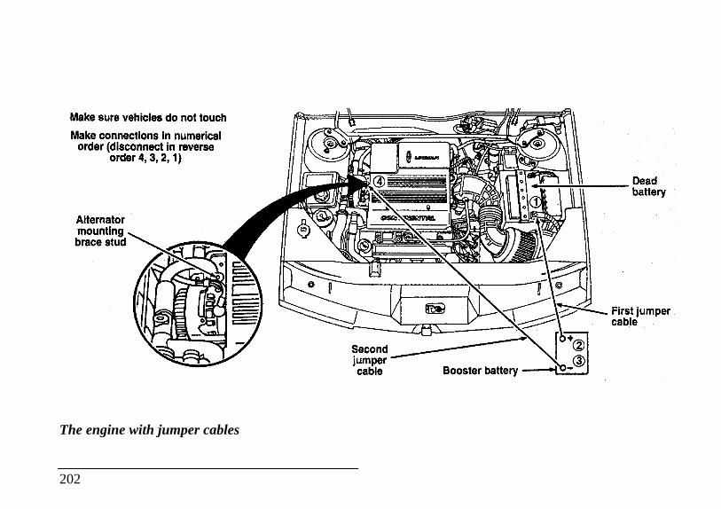
Alternator mounting brace stud jumper cable
The engine with jumper cables
202
Booster battery
Jump-Starting
1. Make sure that the jumper cables are not in theway of moving engine parts, then start thebooster vehicle. Run the engine at a moderatespeed.
2. Let the discharged battery charge for a fewminutes and then start the disabled vehicle. Itmay take a couple of tries before the vehiclestarts. If the vehicle does not start after severalattempts, there may be a different problem.
3. When both vehicles are running, let them idlefor a few minutes to charge the dischargedbattery.
Removing jumper cables
1. Always remove the jumper cables in thereverse order. Remove the negative (-) end ofthe jumper cable from the metallic surface onthe engine or frame of the disabled vehicle.
2. Remove the negative (-) cable from the boosterbattery.
3. Remove the positive (+) cable from the boosterbattery.
4. Remove the other end of the positive (+) cablefrom the discharged battery.
After the vehicle is started, let it idle for a while to letthe engine "relearn" its idle conditions. Drive itaround for a while with all electrical accessoriesturned off to let the battery recharge. You may needto use a battery charger to fully recharge thebattery.
If you need to replace your battery, see Battery in theServicing Your Vehicle chapter.
203
Changing a Tireif you get a flat tire while you are driving, do notapply the brake heavily. Instead, gradually decreasethe speed. Hold the steering wheel firmly andslowly move to a safe place on the side of the road.Park on a level spot, turn off the ignition, set theparking brake, and turn on the hazard flashers.
The Temporary Spare Tire
You may have a high pressure temporary spare tire.This spare tire is smaller than a regular tire and isdesigned for emergency use only. Use it only whenyou get a flat tire and replace it as soon as you can.This spare tire is marked with the words"TEMPORARY USE ONLY" so that you can easilyidentify it.
204
/!\ WARNING
If you use the temporary spare tirecontinuously or do not follow theseprecautions, the tire could fail, causing you tolose control of the vehicle, possibly injuringyourself or others.
When you drive with the temporary spare tire,DO NOT:
exceed 50 mph (80 km/h) under anycircumstances.
load your vehicle so that it is heavier than themaximum vehicle load rating listed on the tiredecal.
tow a trailer.
try to repair the temporary spare tire or remove itfrom its wheel.
use the wheel for any other type of vehicle.
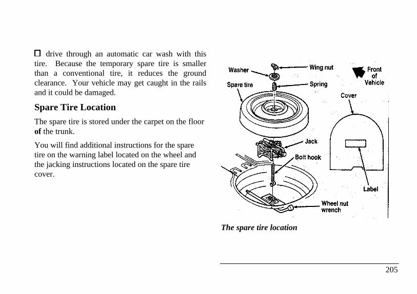
drive through an automatic car wash with thistire. Because the temporary spare tire is smallerthan a conventional tire, it reduces the groundclearance. Your vehicle may get caught in the railsand it could be damaged.
Spare Tire Location
The spare tire is stored under the carpet on the floorof the trunk.
You will find additional instructions for the sparetire on the warning label located on the wheel andthe jacking instructions located on the spare tirecover.
Washer Spare tire Wing nut Spring Jack bolt hook Cover Wheel nut wrench
The spare tire location
205
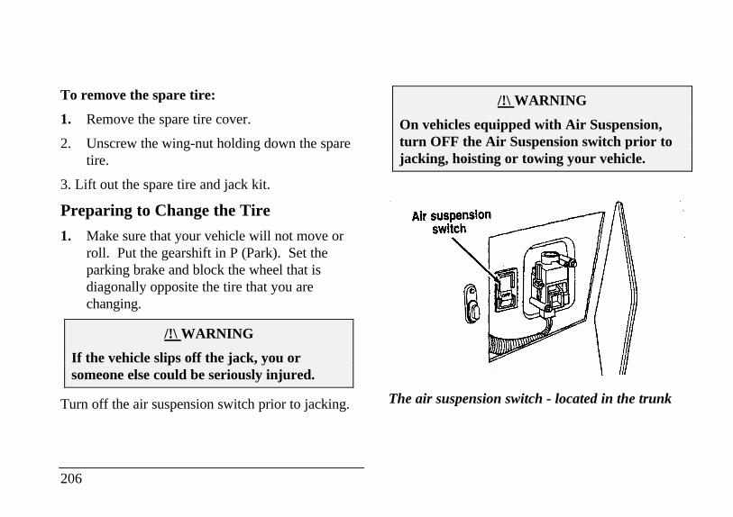
To remove the spare tire:
1. Remove the spare tire cover.
2. Unscrew the wing-nut holding down the sparetire.
3. Lift out the spare tire and jack kit.
Preparing to Change the Tire
1. Make sure that your vehicle will not move orroll. Put the gearshift in P (Park). Set theparking brake and block the wheel that isdiagonally opposite the tire that you arechanging.
/!\ WARNING
If the vehicle slips off the jack, you orsomeone else could be seriously injured.
Turn off the air suspension switch prior to jacking.
206
/!\ WARNING
On vehicles equipped with Air Suspension,turn OFF the Air Suspension switch prior tojacking, hoisting or towing your vehicle.
Air suspension switch
The air suspension switch - located in the trunk
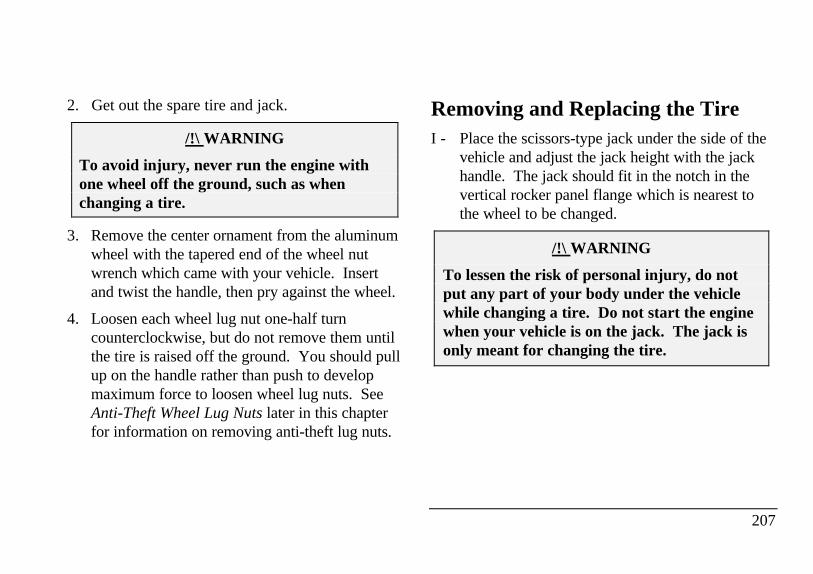
2. Get out the spare tire and jack.
/!\ WARNING
To avoid injury, never run the engine withone wheel off the ground, such as whenchanging a tire.
3. Remove the center ornament from the aluminumwheel with the tapered end of the wheel nutwrench which came with your vehicle. Insertand twist the handle, then pry against the wheel.
4. Loosen each wheel lug nut one-half turncounterclockwise, but do not remove them untilthe tire is raised off the ground. You should pullup on the handle rather than push to developmaximum force to loosen wheel lug nuts. SeeAnti-Theft Wheel Lug Nuts later in this chapterfor information on removing anti-theft lug nuts.
Removing and Replacing the TireI - Place the scissors-type jack under the side of the
vehicle and adjust the jack height with the jackhandle. The jack should fit in the notch in thevertical rocker panel flange which is nearest tothe wheel to be changed.
/!\ WARNING
To lessen the risk of personal injury, do notput any part of your body under the vehiclewhile changing a tire. Do not start the enginewhen your vehicle is on the jack. The jack isonly meant for changing the tire.
207
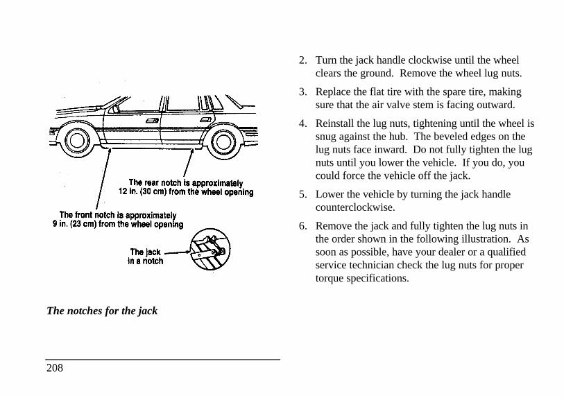
The notches for the jack
208
2. Turn the jack handle clockwise until the wheelclears the ground. Remove the wheel lug nuts.
3. Replace the flat tire with the spare tire, makingsure that the air valve stem is facing outward.
4. Reinstall the lug nuts, tightening until the wheel issnug against the hub. The beveled edges on thelug nuts face inward. Do not fully tighten the lugnuts until you lower the vehicle. If you do, youcould force the vehicle off the jack.
5. Lower the vehicle by turning the jack handlecounterclockwise.
6. Remove the jack and fully tighten the lug nuts inthe order shown in the following illustration. Assoon as possible, have your dealer or a qualifiedservice technician check the lug nuts for propertorque specifications.
7.
8.
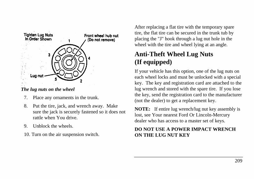
9. Lug nut
The lug nuts on the wheel
7. Place any ornaments in the trunk.
8. Put the tire, jack, and wrench away. Makesure the jack is securely fastened so it does notrattle when You drive.
9. Unblock the wheels.
10. Turn on the air suspension switch.
After replacing a flat tire with the temporary sparetire, the flat tire can be secured in the trunk tub byplacing the "J" hook through a lug nut hole in thewheel with the tire and wheel lying at an angle.
Anti-Theft Wheel Lug Nuts(If equipped)If your vehicle has this option, one of the lug nuts oneach wheel locks and must be unlocked with a specialkey. The key and registration card are attached to thelug wrench and stored with the spare tire. If you losethe key, send the registration card to the manufacturer(not the dealer) to get a replacement key.
NOTE: If entire lug wrench/lug nut key assembly islost, see Your nearest Ford Or Lincoln-Mercurydealer who has access to a master set of keys.
DO NOT USE A POWER IMPACT WRENCHON THE LUG NUT KEY
209
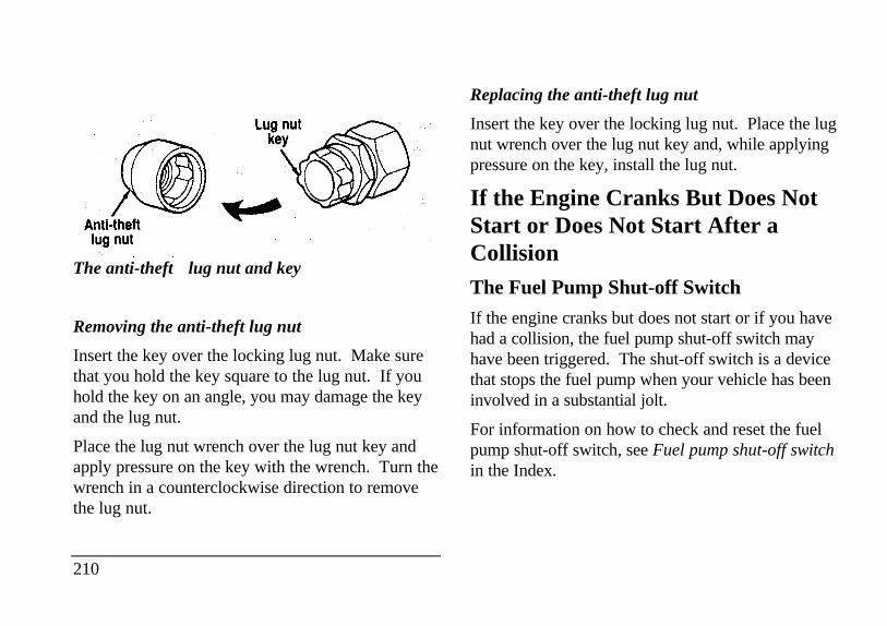
Lug nut key Anti-theft lug nut
The anti-theftft lug nut and key
Removing the anti-theft lug nut
Insert the key over the locking lug nut. Make surethat you hold the key square to the lug nut. If youhold the key on an angle, you may damage the keyand the lug nut.
Place the lug nut wrench over the lug nut key andapply pressure on the key with the wrench. Turn thewrench in a counterclockwise direction to removethe lug nut.
210
Replacing the anti-theft lug nut
Insert the key over the locking lug nut. Place the lugnut wrench over the lug nut key and, while applyingpressure on the key, install the lug nut.
If the Engine Cranks But Does NotStart or Does Not Start After aCollisionThe Fuel Pump Shut-off Switch
If the engine cranks but does not start or if you havehad a collision, the fuel pump shut-off switch mayhave been triggered. The shut-off switch is a devicethat stops the fuel pump when your vehicle has beeninvolved in a substantial jolt.
For information on how to check and reset the fuelpump shut-off switch, see Fuel pump shut-off switchin the Index.
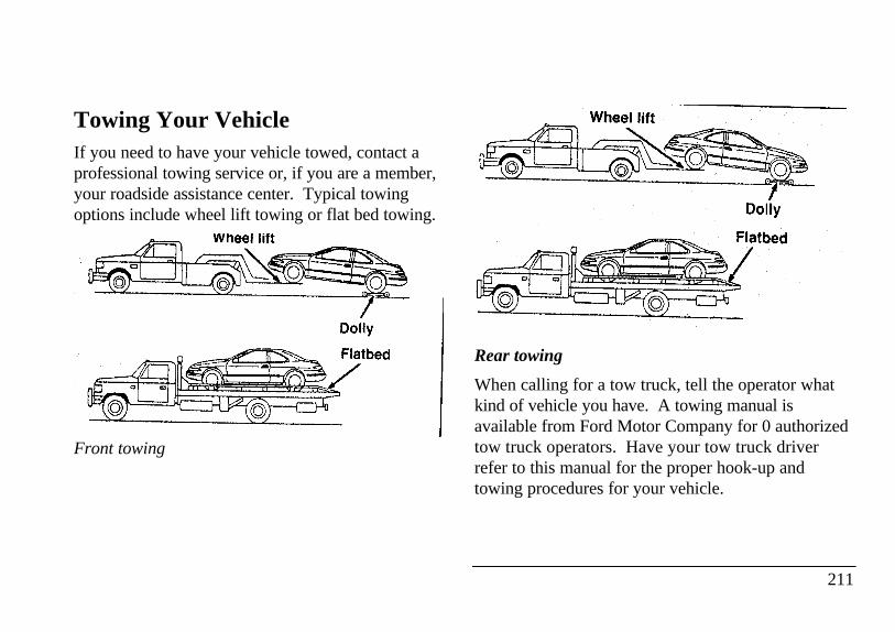
Towing Your VehicleIf you need to have your vehicle towed, contact aprofessional towing service or, if you are a member,your roadside assistance center. Typical towingoptions include wheel lift towing or flat bed towing.
Front towing
Rear towing
When calling for a tow truck, tell the operator whatkind of vehicle you have. A towing manual isavailable from Ford Motor Company for 0 authorizedtow truck operators. Have your tow truck driverrefer to this manual for the proper hook-up andtowing procedures for your vehicle.
211
Lincoln RESCU System
(If equipped)The Lincoln RESCU buttons, located in theoverhead console, should be used in the event thatyou require roadside assistance (out of gas, need atow, etc.) or emergency assistance (involved in anaccident, report a crime or fire, require medicalattention, etc.).
212
See Lincoln RESCU System in the Features chapterfor more information.
Customer AssistanceIf You Have a Service ProblemFord Motor Company has authorized Ford andLincoln-Mercury dealerships that can service yourvehicle for you. This chapter tells you how to getservice or maintenance for your vehicle.
Service/Maintenance Concerns(U.S. or Canada)
Ford recommends taking your vehicle to your sellingdealer who wants to ensure your continuedsatisfaction. You may, however, take your vehicleto any authorized Ford or Lincoln-Mercury dealer.In most cases, your dealer will be able to resolveyour concern.
If you are not satisfied with the service you receivedfrom your dealership's service department, talk to theservice manager at the dealership, or if you still arenot satisfied, talk to the owner or general manager ofthe dealership. In most cases, you will have yourconcern resolved at this level.
If you are away from home when your vehicle needsto be serviced, or if you need more help than thedealer gave you, contact the Ford CustomerAssistance Center to find an authorized dealershipthat may be able to help you.
213
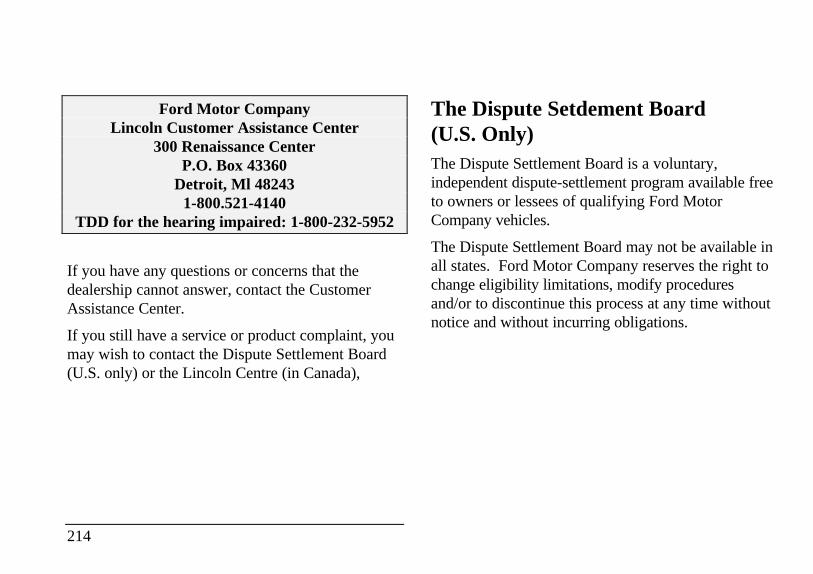
Ford Motor CompanyLincoln Customer Assistance Center
300 Renaissance CenterP.O. Box 43360
Detroit, Ml 482431-800.521-4140
TDD for the hearing impaired: 1-800-232-5952
If you have any questions or concerns that thedealership cannot answer, contact the CustomerAssistance Center.
If you still have a service or product complaint, youmay wish to contact the Dispute Settlement Board(U.S. only) or the Lincoln Centre (in Canada),
214
The Dispute Setdement Board(U.S. Only)The Dispute Settlement Board is a voluntary,independent dispute-settlement program available freeto owners or lessees of qualifying Ford MotorCompany vehicles.
The Dispute Settlement Board may not be available inall states. Ford Motor Company reserves the right tochange eligibility limitations, modify proceduresand/or to discontinue this process at any time withoutnotice and without incurring obligations.
What Kind of Cases Does the BoardReview?The Board reviews all product performance andservice complaints on Ford, Mercury and LincolnCars and Ford and Mercury Light Trucks underwarranty that have not been resolved by a dealer orFord Motor Company.
The Board does not review issues involving:
A non-Ford product
A non-Ford dealership
A vehicle sales transaction
A request for reimbursement of consequentialexpenses unless incidental to a service orproduct complaint being reviewed
Items not covered by your warranty
Alleged liability claims
Property damage where such damage is significantwhen compared to the economic loss alleged underthe warranty dispute
Cases currently in litigation
Vehicles not used primarily for personal, family, orhousehold purposes
NOTE: Complaints involving vehicles on whichapplicable express written new vehicle warrantieshave expired at receipt of your application are noteligible. Eligibility may differ according to state law.For example, see the unique brochure for Californiapurchasers/lessees.
How Does the Board Work?The Board has four members:
three consumer representatives
a Ford or Lincoln-Mercury dealer
Consumer candidates for Board membership arerecruited and trained by an independent consultingfirm. Dealers are chosen because of their businessleadership qualities.
If the involved vehicle is within 36 months and36,000 miles of the date of delivery (warranty startdate), you have a right to make an oral presentationbefore the Board by indicating your choice on theapplication. Also, oral presentations may berequested by the Board. A decision is made by theBoard by simple majority vote.
216
Board members review all the materials related toeach complaint and, based on the availableinformation, arrive at a fair and impartial decision.Decisions are based on the written statements and anyoral presentations made by each of the involvedparties.
Because the Board usually meets only once a month,some cases will take longer than 30 days to bereviewed. The Board will make every effort toresolve each case within 40 days after it receives thecustomer application form.
After your case has been reviewed, the Board willmail you its decision in writing. It will also provideyou with a form to indicate your acceptance orrejection of an award decision. The decisions of theBoard are binding on the dealer and Ford, butcustomers may have other options available to themunder state or federal law.
The decisions of the Board, however, may beintroduced into evidence by any party in subsequentlegal proceedings that may be initiated.
How Do You Contact the Board?
Write to the Board at the following address torequest a brochure/apphcation. You will be sent abrochure and a one-page customer application form.The form should be completed and mailed to thesame address.
Dispute Settlement Board
P.O. Box 5120
Southfield, MI 48086-5120
What is the Review Process?
Your application will be reviewed and if it isdetermined to be eligible, you will receive anacknowledgment indicating the file number assignedto your application and the local Board address. Atthe same time, your dealer and Ford Motor Companyrepresentative are asked to submit statements.
To review your case properly, the Board needs the
following information:
legible copies of all documents and maintenanceor repair orders that relate to the case
the year, make, model, and vehicle identificationnumber
the date you bought your vehicle
217
the date of repair and the mileage at the time ofrepair
the current mileage
the name of the dealer who sold you the vehicleor who serviced your vehicle
a brief description of your unresolved complaint
a brief summary of actions that were taken withthe dealer and Ford Motor Company
the names (if known) of all people you contactedat the dealership
a description of the action you want done toresolve your concern.
Should your application NOT qualify for review, anexplanation will be mailed to you.
218
Reporting Safety Defects(U.S. Only)If you believe that your vehicle has a defect whichcould cause a crash or could cause injury or death,you should immediately inform the National HighwayTraffic Safety Administration (NHTSA) in addition tonotifying Ford Motor Company.
If NHTSA receives similar complaints, it may open aninvestigation, and if it finds that a safety defect existsin a group of vehicles, it may order a recall andremedy campaign. However, NHTSA cannot becomeinvolved in individual problems between you, yourdealer, or Ford Motor Company.
To contact NHTSA, you may either call the AutoSafety Hotline toll-free at 1-800-424-9393 (or 366-0123 in the Washington, D.C. area) or write to:NHTSA, U.S. Department of Transportation, 400Seventh Street, Washington D.C. 20590. You canalso obtain other information about motor vehiclesafety from the Hotline.
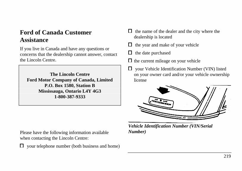
Ford of Canada CustomerAssistanceIf you live in Canada and have any questions orconcerns that the dealership cannot answer, contactthe Lincoln Centre.
The Lincoln CentreFord Motor Company of Canada, Limited
P.O. Box 1580, Station BMississauga, Ontario L4Y 4G3
1-800-387-9333
Please have the following information availablewhen contacting the Lincoln Centre:
your telephone number (both business and home)
the name of the dealer and the city where thedealership is located
the year and make of your vehicle
the date purchased
the current mileage on your vehicle
your Vehicle Identification Number (VIN) listedon your owner card and/or your vehicle ownershiplicense
Vehicle Identification Number (VIN/SerialNumber)
219
Canadian Motor Vehicle Arbitration Plan(CAMVAP)
If a specific item of concern arises, where a solutioncannot be reached between a vehicle owner, Ford ofCanada, and/or one of its dealers (that all parties canagree upon), the owner may wish to use the servicesoffered by the Canadian Motor Vehicle ArbitrationPlan (CAMVAP).
CAMVAP uses the services of ProvincialAdministrators to assist consumers in scheduling andpreparing for their arbitration hearings. However,before you can proceed with CAMVAP you mustfollow your manufacturer's dispute resolutionprocess as outlined under "Service/MaintenanceConcerns (U.S. or Canada)" earlier in this chapter.
220
Consumers wishing to obtain further informationabout the program can obtain an information bookletfrom your dealer or contact the ProvincialAdministrator, Canadian Motor Vehicle ArbitrationPlan, at the address or telephone number shownbelow.
0 & P Services
595 Bay Street - Suite 300
Toronto, Ontario
M5G 2C2
Telephone 1 (800) 207-0685
Getting Help Outside the U.S. andCanadaBefore you export your vehicle to a foreign country,contact the appropriate foreign embassy or consulateto make sure local regulations do not prevent youfrom registering your vehicle. Officials at theembassy can also help you decide whether youshould import your vehicle to that country.
Officials at the embassy or consulate can tell youwhere to get unleaded fuel. If you cannot getunleaded fuel or can get only fuel with an anti-knockindex that is lower than your vehicle needs, contacta district or owner relations office before you leavethe U.S. or Canada.
Use of leaded fuel in your vehicle without a properconversion may damage the effectiveness of youremissions control system and may cause engineknocking or serious engine damage. Ford MotorCompany is not responsible for any damage that iscaused by use of improper fuel.
You may also have difficulty importing your vehicleback into the U.S. if you use leaded fuel.
If your vehicle must be serviced while you aretraveling or living in Central or South America, theCaribbean, or the Middle East, contact the nearestFord dealership. If the dealership cannot help you,write to:
Ford Motor CompanyExport Operations
1555 Fairlane BusinessPark #3
Allen Park, MI 481 olU.S.A.
Phone: 313-317-4282Fax: 313-390-0804
221
If you are in other foreign countries, contact thenearest Ford dealership. If the dealership cannothelp you, they can direct you to the appropriateFord affiliate office.
222
If you buy your vehicle in North America and thenrelocate outside of the U.S. or Canada, register yourVehicle Identification Number and new address withFord Motor Company Export Operations.
Accessories
Ford Accessories for Your VehicleA wide selection of accessories is available throughyour local authorized dealer. These fine accessorieshave been engineered specifically to fulfill yourautomotive needs. They are custom designed tocomplement the style and aerodynamic appearanceof your Ford-built vehicle. In addition, eachaccessory is made from high quality materials andmeets or exceeds Ford's rigid engineering and safetyspecifications. That is why Ford brand accessoriesare warranted for up to 3 years or 36,000 miles(60,000 km), whichever comes first. See yourdealer for complete warranty information andaccessory availability.
Ford has many fine products available from yourdealer to clean your vehicle and protect its finishes.For best results, use the following, or products ofequivalent quality:
Ford Custom Clear Coat Polish
Ford Custom Silicone Gloss Polish
Ford Custom Vinyl Protectant
Ford Deluxe Leather and Vinyl Cleaner
Ford Extra Strength Spot and Stain Remover
Ford Extra Strength Tar and Road Oil Remover
Ford Extra Strength Upholstery Cleaner
Ford Extra Strength Whitewall Tire Cleaner
Ford Multi-Purpose Cleaner
Ford Premium Car Wash Concentrate
Ford Triple Clean
Ford Ultra-Clear Spray Glass Cleaner
223
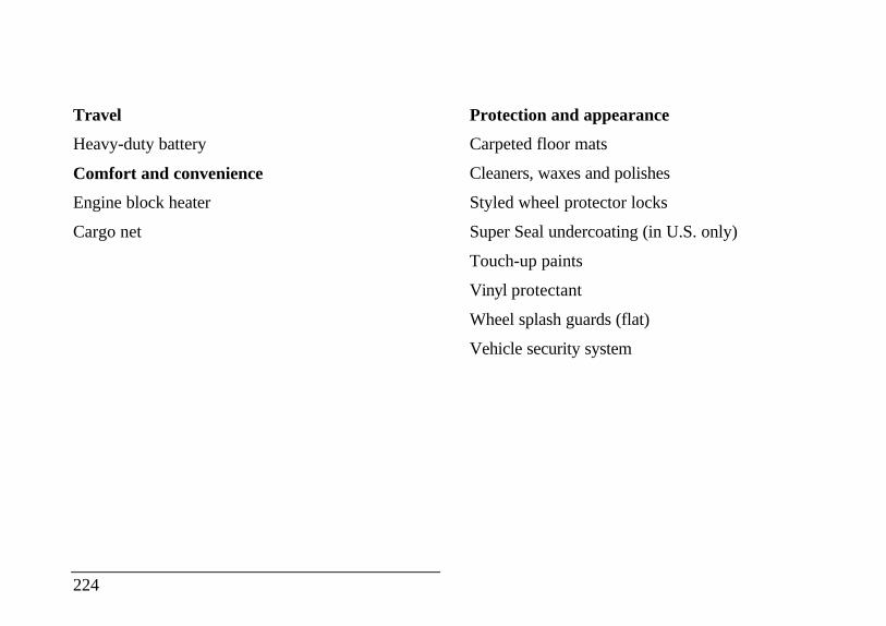
Travel
Heavy-duty battery
Comfort and convenience
Engine block heater
Cargo net
224
Protection and appearance
Carpeted floor mats
Cleaners, waxes and polishes
Styled wheel protector locks
Super Seal undercoating (in U.S. only)
Touch-up paints
Vinyl protectant
Wheel splash guards (flat)
Vehicle security system
NOTE: When adding accessories, equipment,passengers, and luggage to your vehicle, do notexceed the total weight capacity of the vehicle or ofthe front or rear axle (GVWR, GAWR as shown onthe Safety Compliance Certification Label). Consultyour dealer for specific weight information.
NOTE: The Federal Communications Commission(FCC) or in Canada the Canadian RadioTelecommunications Commission (CRTC) regulatesthe use of mobile communications systems - such astwo-way radios, telephones, and theft alarms thatare equipped with radio transmitters. Any suchequipment installed in your vehicle should complywith FCC or in Canada the CRTC regulation andshould be installed only by a qualified technician.
NOTE: Mobile communications systems may harmthe operation of your vehicle, particularly if they arenot properly designed for automotive use or are notproperly installed. For example, when operated, suchsystems may cause the engine to stumble or stall. Inaddition, such systems may themselves be damaged ortheir operation affected by operating your vehicle.(Citizens band CB transceivers, garage door openers,and other transmitters whose power output is 5 wattsor less will not ordinarily affect your vehicle'soperation.)
NOTE: Because we have no control over theinstallation, design, or manufacture of such systems,Ford cannot assume responsibility for any adverseeffects or damage that may result if you use thisequipment.
225
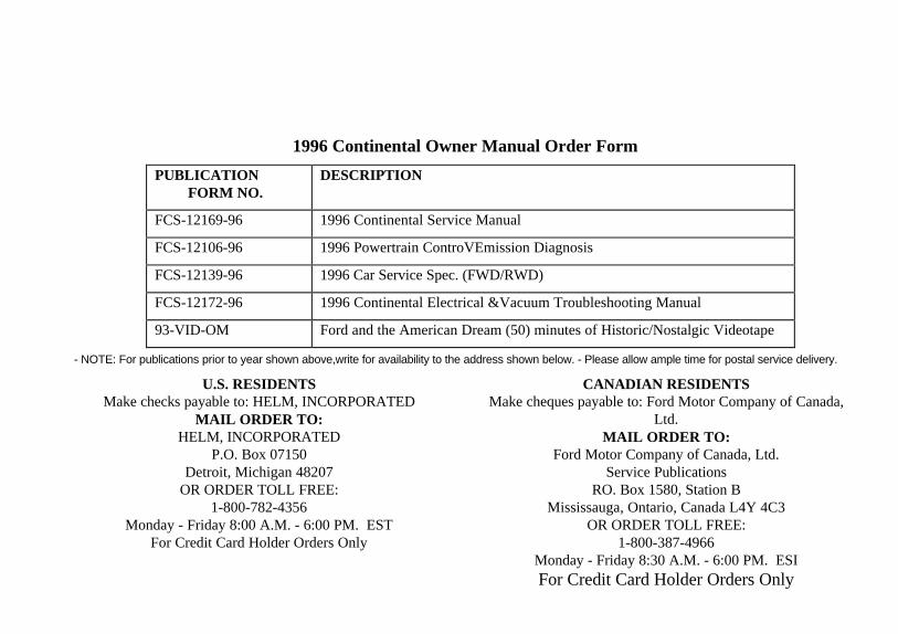
1996 Continental Owner Manual Order Form
PUBLICATIONFORM NO.
DESCRIPTION
FCS-12169-96 1996 Continental Service Manual
FCS-12106-96 1996 Powertrain ControVEmission Diagnosis
FCS-12139-96 1996 Car Service Spec. (FWD/RWD)
FCS-12172-96 1996 Continental Electrical &Vacuum Troubleshooting Manual
93-VID-OM Ford and the American Dream (50) minutes of Historic/Nostalgic Videotape
- NOTE: For publications prior to year shown above,write for availability to the address shown below. - Please allow ample time for postal service delivery.
U.S. RESIDENTSMake checks payable to: HELM, INCORPORATED
MAIL ORDER TO:HELM, INCORPORATED
P.O. Box 07150Detroit, Michigan 48207
OR ORDER TOLL FREE:1-800-782-4356
Monday - Friday 8:00 A.M. - 6:00 PM. ESTFor Credit Card Holder Orders Only
CANADIAN RESIDENTSMake cheques payable to: Ford Motor Company of Canada,
Ltd.MAIL ORDER TO:
Ford Motor Company of Canada, Ltd.Service Publications
RO. Box 1580, Station BMississauga, Ontario, Canada L4Y 4C3
OR ORDER TOLL FREE:1-800-387-4966
Monday - Friday 8:30 A.M. - 6:00 PM. ESIFor Credit Card Holder Orders Only
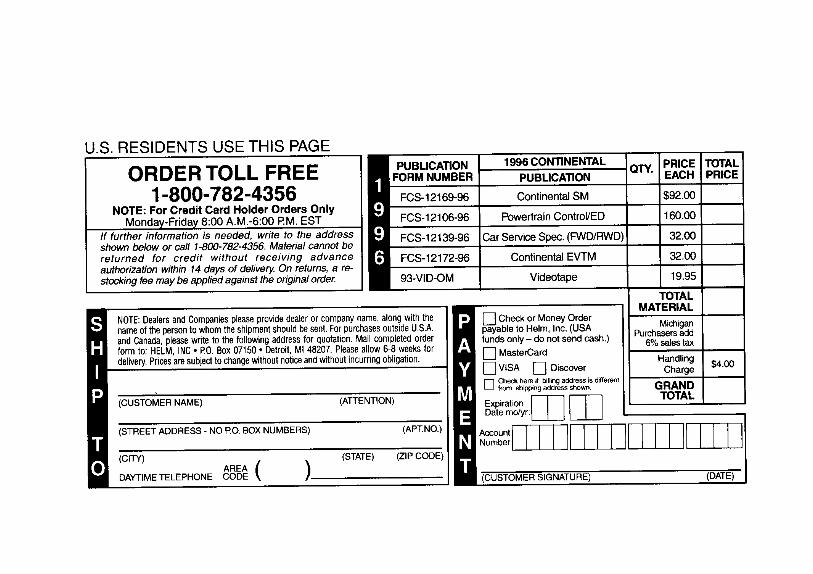
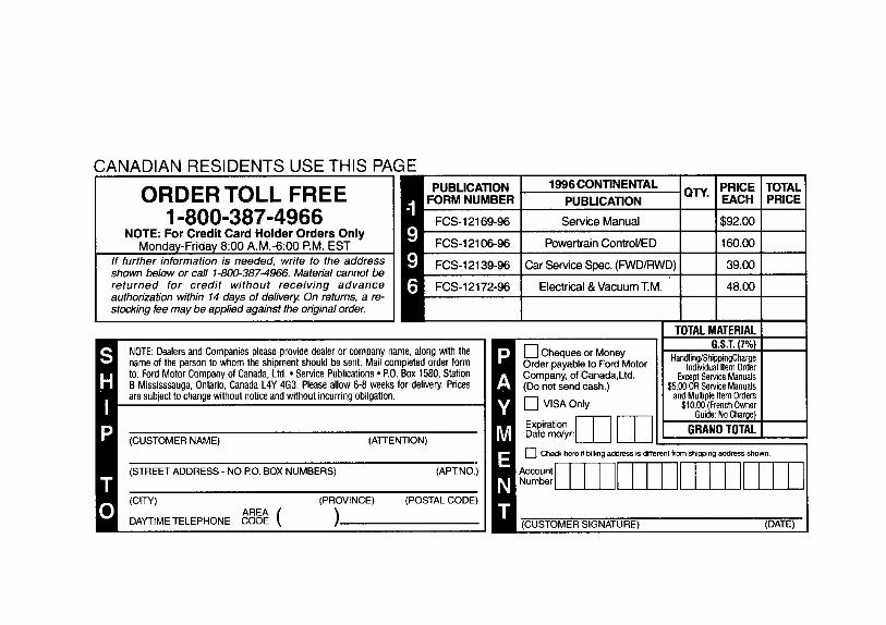
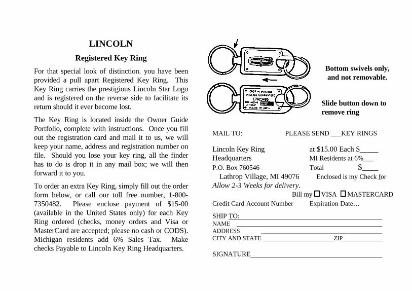
LINCOLN
Registered Key Ring
For that special look of distinction. you have beenprovided a pull apart Registered Key Ring. ThisKey Ring carries the prestigious Lincoln Star Logoand is registered on the reverse side to facilitate itsreturn should it ever become lost.
The Key Ring is located inside the Owner GuidePortfolio, complete with instructions. Once you fillout the registration card and mail it to us, we willkeep your name, address and registration number onfile. Should you lose your key ring, all the finderhas to do is drop it in any mail box; we will thenforward it to you.
To order an extra Key Ring, simply fill out the orderform below, or call our toll free number, 1-800-7350482. Please enclose payment of $15-00(available in the United States only) for each KeyRing ordered (checks, money orders and Visa orMasterCard are accepted; please no cash or CODS).Michigan residents add 6% Sales Tax. Makechecks Payable to Lincoln Key Ring Headquarters.
Bottom swivels only,and not removable.
Slide button down toremove ring
MAIL TO: PLEASE SEND ___KEY RINGS
Lincoln Key Ring at $15.00 Each $_____Headquarters MI Residents at 6%___P.O. Box 760546 Total $____
Lathrop Village, MI 49076 Enclosed is my Check forAllow 2-3 Weeks for delivery.
Bill my VISA MASTERCARDCredit Card Account Number Expiration Date...
SHIP TO: NAME ADDRESS CITY AND STATE ZIP
SIGNATURE
Servicing Your Continental
Service Made EasyFord has two goals for servicing your vehicle.
1. When we can, we design parts that do notneed to be serviced.
2. We want to make servicing your vehicle aseasy as possible. To help you:
We highlight do-it-yourself items in yellow inthe engine compartment so that you can find themeasily.
When possible, we design - such as theheadlamp bulbs-- that can be replaced withouttools.
We give you a Maintenance Schedule thatmakes tracking routine service for your vehicleeasy. The maintenance schedule is located inthe Maintenance Schedule and Record booklet.
This chapter tells you about the basic parts that youneed to check and service regularly.
If your vehicle needs professional servicing, yourdealership can provide the parts and service required.Check your Warranty Information Booklet to find outwhich parts and services are covered. Also see theCustomer Assistance chapter of this Owner Guide.
Ford Motor Company recommends that the OwnerMaintenance Checks listed in the MaintenanceSchedule and Record booklet be performed for theproper operation of your vehicle. In addition to theconditions listed in the Owner Maintenance Checklist,be alert for any unusual noise, vibration, or otherindication that your vehicle may need service. If youdo notice something unusual, see that your vehicle isserviced promptly.
231
Use only recommended fuels, lubricants, fluids,and service parts conforming to Fordspecifications. Motorcraft parts are designed andbuilt to provide the best performance in yourvehicle. Using these parts for replacement is yourassurance that Ford-buflt quality stays in yourvehicle.
NOTE: Always dispose of used automotive fluidsin a responsible manner. Follow your community'sstandards for disposing of these types of fluids.Call your local recycling center to find out aboutrecycling automotive fluids.
Accident DamageShould your vehicle suffer accident damagerequiring new sheet metal or plastic replacementparts, be sure your repair shop uses only genuineFord replacement parts.
While imitation body parts may appear similar togenuine Ford parts on the surface, differences in
232
quality become obvious when both are subjected tostandard Ford quality tests.
Ford tests indicate that you should be concerned withthe quality of the fit and finish, corrosion resistanceand structural integrity of these imitation replacementparts, and how their use will affect your warranty.
How Can You Protect Yourself?.Before any repair work begins, tell your adjuster thatyou want your vehicle repaired using only genuineFord body parts. If the adjuster refuses, contact yourinsurance agent for help. If your agent and yourinsurance company refuse to repair your vehicle withoriginal factory parts, you should contact your stateinsurance commissioner, the National Highway TrafficSafety Administration or a local consumer protectionagency.
In Canada, contact provincial insurancecommissioners, Transport Canada or local consumerprotection groups.
Precautions When Servicing YourVehicleBe especially careful when inspecting or servicingyour vehicle. Here are some general precautionsfor your safety:
Do not work on a hot engine. The enginecooling fan may come on unexpectedly. Alwaysturn the engine off and let it cool.
/!\ WARNING
The cooling fan is automatic and may comeon at any time. Always disconnect thenegative terminal of the battery beforeworking near the fan.
If you must work with the engine running,avoid wearing loose clothing or jewelry thatcould get caught in moving parts. Takeappropriate precautions with long hair.
Do not work on a vehicle in an enclosed spacewith the engine running, unless you are sure youhave enough ventilation.
Never get under a vehicle while it is supported by ajack only. If you must work under a vehicle, usesafety stands.
Keep all lit cigarettes and other smoking materialsaway from the battery and all fuel-related parts.
If you disconnect the battery, the engine must“relearn" its idle conditions before your vehicle willdrive properly. To find out how the engine does this,see Battery in this chapter.
Working with the engine off.
1. Set the parking brake fully and make sure that thegearshift is securely latched in P (Park).
2. Remove the key from the ignition after you turnthe engine off.
233
3. Block the wheels. This will prevent yourvehicle from moving unexpectedly.
Working with the engine on:
1. Set the parking brake fully and make sure thatthe gearshift is securely latched in P (Park).
2. Block the wheels. This will prevent yourvehicle from moving unexpectedly.
/!\ WARNING
Do not start your engine with the aircleaner removed and do not remove it whilethe engine is running.
/!\ WARNING
The cooling fan is automatic and may comeon at any time. Always disconnect thenegative terminal of the battery beforeworking near the fan.
234
If the battery is disconnected' the computer must
releam its idle control. See Battery in the Index.
NOTE: The engine compartment light may beswitched on or off at the light assembly. The lightassembly is located on the hood on the driver's side.To turn the light on, pull the switch toward you; toturn it off, push it away from you. The switch mayremain in the on position at all times, as the light willturn off when the hood is closed.
Opening the Hood
1. Inside the vehicle, pull the hood release handlelocated under the bottom left comer of theinstrument panel.
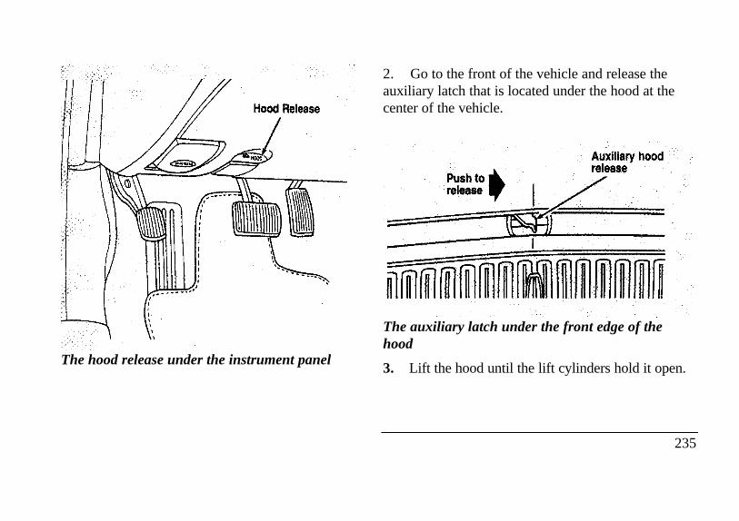
The hood release under the instrument panel
2. Go to the front of the vehicle and release theauxiliary latch that is located under the hood at thecenter of the vehicle.Auxiliary hood release
The auxiliary latch under the front edge of thehood
3. Lift the hood until the lift cylinders hold it open.
235
Whenever you close the hood, latch it securely.
NOTE: Apply lubricant to the hood latch at six-month intervals to maintain smooth and trouble-free operation.
NOTE: Read and understand Precautions WhenServicing Your Vehicle at the beginning of thischapter before opening the hood.
236
Engine CompartmentYour vehicle has a 4.6 liter 4V SFI engine. Thefollowing page shows a diagram of where to finditems that you should regularly service.
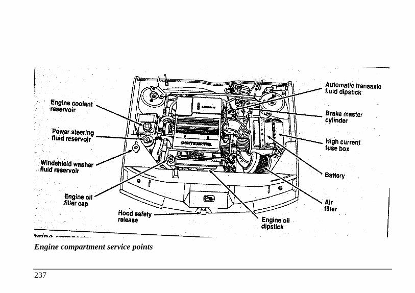
Engine coolant reservoir Power steering fluid reservoir Windshield washer fluid reservoir Engine oil filler cap Hood safety release High current fuse box Engine oildipstick Air filter
Engine compartment service points
237
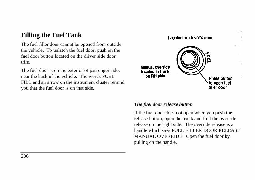
Filling the Fuel TankThe fuel filler door cannot be opened from outsidethe vehicle. To unlatch the fuel door, push on thefuel door button located on the driver side doortrim.
The fuel door is on the exterior of passenger side,near the back of the vehicle. The words FUELFILL and an arrow on the instrument cluster remindyou that the fuel door is on that side.
238
Manual override fuel filler door
The fuel door release button
If the fuel door does not open when you push therelease button, open the trunk and find the overriderelease on the right side. The override release is ahandle which says FUEL FILLER DOOR RELEASEMANUAL OVERRIDE. Open the fuel door bypulling on the handle.
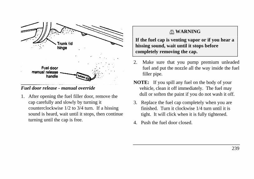
Fuel door release - manual override
1. After opening the fuel filler door, remove thecap carefully and slowly by turning itcounterclockwise 1/2 to 3/4 turn. If a hissingsound is heard, wait until it stops, then continueturning until the cap is free.
/!\ WARNING
If the fuel cap is venting vapor or if you hear ahissing sound, wait until it stops beforecompletely removing the cap.
2. Make sure that you pump premium unleadedfuel and put the nozzle all the way inside the fuelfiller pipe.
NOTE: If you spill any fuel on the body of yourvehicle, clean it off immediately. The fuel maydull or soften the paint if you do not wash it off.
3. Replace the fuel cap completely when you arefinished. Turn it clockwise 1/4 turn until it istight. It will click when it is fully tightened.
4. Push the fuel door closed.
239
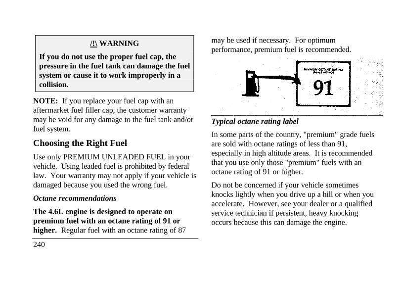
/!\ WARNING
If you do not use the proper fuel cap, thepressure in the fuel tank can damage the fuelsystem or cause it to work improperly in acollision.
NOTE: If you replace your fuel cap with anaftermarket fuel filler cap, the customer warrantymay be void for any damage to the fuel tank and/orfuel system.
Choosing the Right Fuel
Use only PREMIUM UNLEADED FUEL in yourvehicle. Using leaded fuel is prohibited by federallaw. Your warranty may not apply if your vehicle isdamaged because you used the wrong fuel.
Octane recommendations
The 4.6L engine is designed to operate onpremium fuel with an octane rating of 91 orhigher. Regular fuel with an octane rating of 87
240
may be used if necessary. For optimumperformance, premium fuel is recommended.
Typical octane rating label
In some parts of the country, "premium" grade fuelsare sold with octane ratings of less than 91,especially in high altitude areas. It is recommendedthat you use only those "premium" fuels with anoctane rating of 91 or higher.
Do not be concerned if your vehicle sometimesknocks lightly when you drive up a hill or when youaccelerate. However, see your dealer or a qualifiedservice technician if persistent, heavy knockingoccurs because this can damage the engine.
If you are experiencing starting, rough idle orhesitation problems when the engine is cold, it maybe caused by fuel with low volatility. Try a differentbrand of fuel. If the condition persists, see yourdealer or a qualified service technician.
Gasolines for clean air
Fuels in certain areas of the country are required tocontain oxygenates to improve air quality.Common oxygenates are ethanol or grain alcohol(blended at no more than 10%), methanol or woodalcohol (blended at no more than 5% withcosolvents and additives), and MTBE or methyltertiary butyl ether (blended at no more than 15%).
Generally, you should not experience difficultiesoperating your vehicle on fuels containingoxygenates. We encourage you to use these fuels.
Safety Information Relating to AutomotiveFuels
/!\ WARNING
Automotive fuels can cause serious injury ordeath if misused or mishandled.
Turn vehicle off when refueling.
Do not smoke when refueling. Fuels areextremely flammable.
Do not siphon any fuel by mouth.
/!\ WARNING
Gasoline or gasoline blended with methanolcan cause blindness and possible death whenswallowed. If any fuel is swallowed, callphysician or poison control centerimmediately.
241
Avoid breathing vapors while refueling.
If fuel is splashed on the skin, wash with soapand water.
If fuel is splashed in the eyes, remove contactlenses (if worn), flush with water for 15 minutes,and seek medical attention.
Gasoline and gasoline blends may contain smallamounts of carcinogens, such as benzene. Long-term exposure to unleaded gasoline vapors hascaused cancer in laboratory animals.
if you are taking the medication "Antabuse" orother forms of disulfiram for the treatment ofalcoholism, vapor or skin contact with a gasoline-methanol blend, may cause the same kind of adversereaction as drinking an alcoholic beverage. Insensitive individuals, serious personal injury orsickness could result. Consult a physician promptlyif you experience an adverse reaction.
242
Running Out of Fuel
NOTE: Avoid running out of fuel because thissituation may have an adverse effect on modernpowertrain components.
You may need to crank the engine several timesbefore the fuel system starts to pump fuel from thetank to the engine.
If the engine does not start, check the fuel pumpshut-off switch and reset as required. See Fuel pumpshut-off switch in the Index.
/!\ WARNING
Never pour fuel in the throttle body orattempt to start the engine with the aircleaner removed. Doing so could result infire and personal injury.
Fuel Economy
Fuel economy is an estimate of the efficiency ofyour vehicle and can be calculated as Miles PerGallon (MPG) or liters Per 100 Kilometers (L/100K).
Do not calculate fuel economy during your vehicle'sbreak-in period. This would not be an accurateestimate of how much fuel your vehicle willnormally use.
To calculate fuel economy:
I . Fill the tank completely and record the initialodometer reading.
2. Every time you buy fuel record the amount (ingallons or liters) purchased.
3. After at least three to five tankfuls, fill the fueltank and record the final odometer reading.
4. Use these equations to calculate your fueleconomy.
English: MPG = (total miles)/(gallons used).
Metric: L/100K = (liters used) x 100/(totalkilometers)
Comparisons With EPA Fuel EconomyEstimates
EPA fuel economy figures are obtained fromlaboratory tests under simulated road conditions andmay not reflect the actual conditions you experienceor your style of driving. The EPA fuel economyestimate is not a guarantee that you will achieve thefuel economy shown.
The following decrease fuel economy:
Lack of regular, scheduled maintenance
Rapid acceleration and excessive speed
Driving with your foot on the brake
Sudden stops
Extended engine idling
243
Using speed control in hilly terrain
Extended use of the A/C, defroster, rear windowdefroster and other accessories
Underinflated tires
Heavy loads
Aftermarket add-ons such as bike, ski or luggageracks, bug deflectors, etc.
Self-Service Pointers
If you choose to do your own fueling, you shouldalso perform a few simple maintenance routines.This extra effort will save you additional money andcontribute to the driving efficiency of your vehicle.
The following procedures require only a tire gauge,a rag, an oil can spout and windshield washer fluid.
Check the engine oil at every refueling stop
Clean the windshield, outside mirrors andheadlights
244
Check windshield washer fluid
Check tires for excessive wear or worn edges
Check the tire pressure at least monthly
Engine Oil RecommendationsWe recommend using Motorcraft oil or an equivalentoil meeting Ford Specification ESE-M2C153-E anddisplaying the American Petroleum InstituteCERTIFICATION MARK on the front of thecontainer.
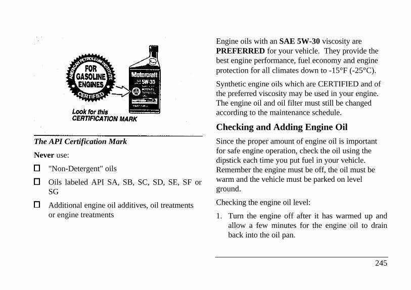
The API Certification Mark
Never use:
"Non-Detergent" oils
Oils labeled API SA, SB, SC, SD, SE, SF orSG
Additional engine oil additives, oil treatmentsor engine treatments
Engine oils with an SAE 5W-30 viscosity arePREFERRED for your vehicle. They provide thebest engine performance, fuel economy and engineprotection for all climates down to -15°F (-25°C).
Synthetic engine oils which are CERTIFIED and ofthe preferred viscosity may be used in your engine.The engine oil and oil filter must still be changedaccording to the maintenance schedule.
Checking and Adding Engine Oil
Since the proper amount of engine oil is importantfor safe engine operation, check the oil using thedipstick each time you put fuel in your vehicle.Remember the engine must be off, the oil must bewarm and the vehicle must be parked on levelground.
Checking the engine oil level:
1. Turn the engine off after it has warmed up andallow a few minutes for the engine oil to drainback into the oil pan.
245
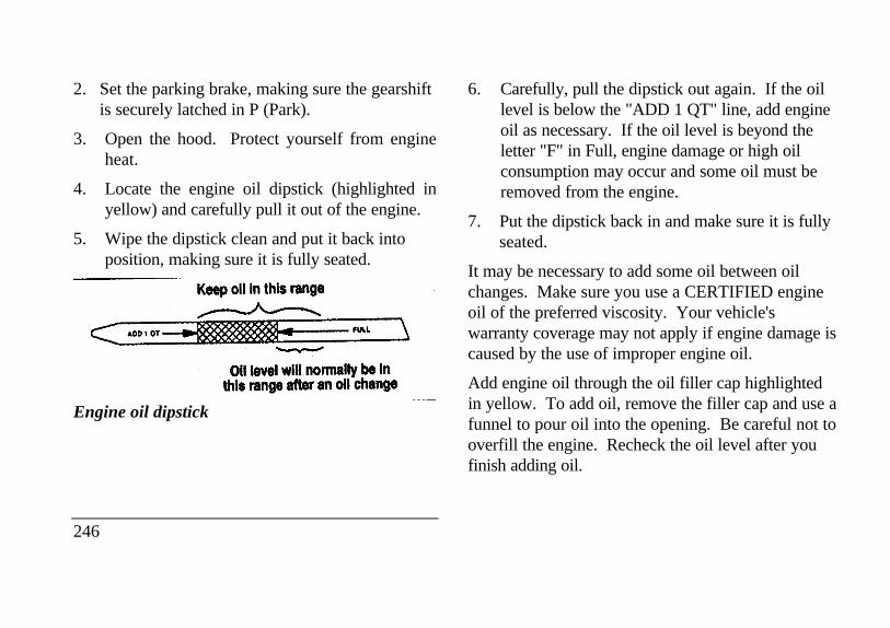
2. Set the parking brake, making sure the gearshiftis securely latched in P (Park).
3. Open the hood. Protect yourself from engineheat.
4. Locate the engine oil dipstick (highlighted inyellow) and carefully pull it out of the engine.
5. Wipe the dipstick clean and put it back intoposition, making sure it is fully seated.
Engine oil dipstick
246
6. Carefully, pull the dipstick out again. If the oillevel is below the "ADD 1 QT" line, add engineoil as necessary. If the oil level is beyond theletter "F" in Full, engine damage or high oilconsumption may occur and some oil must beremoved from the engine.
7. Put the dipstick back in and make sure it is fullyseated.
It may be necessary to add some oil between oilchanges. Make sure you use a CERTIFIED engineoil of the preferred viscosity. Your vehicle'swarranty coverage may not apply if engine damage iscaused by the use of improper engine oil.
Add engine oil through the oil filler cap highlightedin yellow. To add oil, remove the filler cap and use afunnel to pour oil into the opening. Be careful not tooverfill the engine. Recheck the oil level after youfinish adding oil.
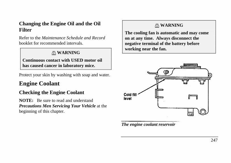
Changing the Engine Oil and the OilFilter
Refer to the Maintenance Schedule and Recordbooklet for recommended intervals.
/!\ WARNING
Continuous contact with USED motor oilhas caused cancer in laboratory mice.
Protect your skin by washing with soap and water.
Engine CoolantChecking the Engine Coolant
NOTE: Be sure to read and understandPrecautions Men Servicing Your Vehicle at thebeginning of this chapter.
/!\ WARNING
The cooling fan is automatic and may comeon at any time. Always disconnect thenegative terminal of the battery beforeworking near the fan.
Cold fill level
The engine coolant reservoir
247
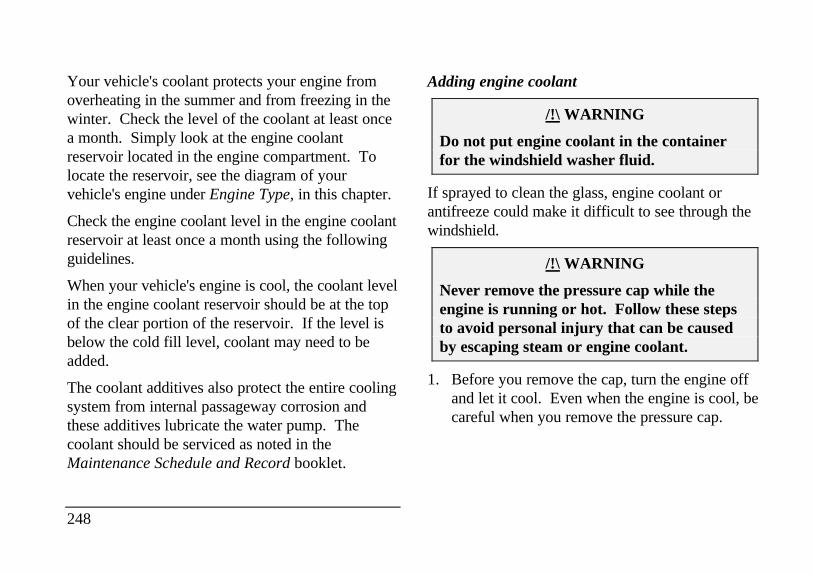
Your vehicle's coolant protects your engine fromoverheating in the summer and from freezing in thewinter. Check the level of the coolant at least oncea month. Simply look at the engine coolantreservoir located in the engine compartment. Tolocate the reservoir, see the diagram of yourvehicle's engine under Engine Type, in this chapter.
Check the engine coolant level in the engine coolantreservoir at least once a month using the followingguidelines.
When your vehicle's engine is cool, the coolant levelin the engine coolant reservoir should be at the topof the clear portion of the reservoir. If the level isbelow the cold fill level, coolant may need to beadded.
The coolant additives also protect the entire coolingsystem from internal passageway corrosion andthese additives lubricate the water pump. Thecoolant should be serviced as noted in theMaintenance Schedule and Record booklet.
248
Adding engine coolant
/!\ WARNING
Do not put engine coolant in the containerfor the windshield washer fluid.
If sprayed to clean the glass, engine coolant orantifreeze could make it difficult to see through thewindshield.
/!\ WARNING
Never remove the pressure cap while theengine is running or hot. Follow these stepsto avoid personal injury that can be causedby escaping steam or engine coolant.
1. Before you remove the cap, turn the engine offand let it cool. Even when the engine is cool, becareful when you remove the pressure cap.
2. When the engine is cool, wrap a thick clotharound the cap and turn it slowly counter-clockwise to relieve pressure.
3. Step back while the pressure releases.
4. When you are sure that all the pressure hasbeen released, use the cloth to turn and removecap.
5. Stand away from the reservoir opening. Hotsteam may blow out or hot engine coolant mayeven splash out.
/!\ WARNING
Failure to follow these instructions couldresult in serious personal injury from hotengine coolant or steam blowout and/ordamage to the engine cooling system orengine.
To find out how much engine coolant mixture yourvehicle's coolant system can hold, see Refillcapacities for fluids in the Index.
Add engine coolant only to the coolant reservoir.If the coolant level is low, add to the reservoir a50/50 or appropriate mixture of water and the typeof engine coolant that Ford specifies. You may addwater by itself only in an emergency, but you shouldreplace it with a 50/50 mixture as soon as possible.Check the engine coolant again the next few timesyou drive your vehicle.
Have your dealer check the engine cooling systemfor leaks if you have to add more than a quart (liter)of engine coolant more than once a month.
Ford Premium Cooling System Fluid is an optimizedformula that will protect all metals and rubberelastomers used in Ford engines for four years or50,000 miles (80,000 km). It is not necessary andnot recommended to use supplemental coolantadditives in your vehicle. These additives may harm
249
your engine cooling system. Follow therecommended service interval for changing yourengine coolant.
NOTE: When you change or add engine coolant, itis important to maintain your engine coolantconcentration between 40% (-11°F [-24°C]) and60% (-62°F [-52°C]), depending on your localclimate conditions. Below 40% you will lose freezeprotection; above 60% your engine may overheaton a warm day.
NOTE: Less than 40% of coolant concentrationmay cause engine corrosion and overheating. Plainwater may be used in an emergency only. Replaceit with the specified coolant as quickly as possible.
NOTE: The use of an improper coolant may voidyour warranty for the engine cooling system. Useonly a premium, nationally recognized brand nameengine coolant. Do not use alcohol, methanolantifreeze or engine coolant mixed with alcohol ormethanol antifreeze. If you do not use the proper
250
coolant, the aluminum engine on your vehicle willcorrode.
Ford Motor Company expressly authorizes the FordRotunda engine coolant recycling process andchemicals. Use only Ford Rotunda recycled enginecoolant or an equivalent recycled engine coolant thatis certified by the supplier to meet Ford specificationESE-M97B44-A.
NOTE: Always dispose of used automotive fluidsin a responsible manner. Follow your community'sstandards for disposing of these types of fluids. Callyour local recycling center to find out aboutrecycling automotive fluids.
Use Ford Premium Cooling System Fluid E2FZ-19549-AA (in Canada, Motorcraft CXC-8-B) or anequivalent engine coolant that meets FordSpecification ESE-M97B44-A.
Engine coolant drain and flush
Proper procedures for a complete coolant drain andflush of the cooling system can be found in the CarService Manual. Following these recommendedprocedures will ensure that the specified coolantlevel and a 50/50 or appropriate mixture of coolantand water is maintained.
Engine coolant refill procedure
When the entire cooling system is drained andrefilled, the following procedure should be used toensure a complete fill:
NOTE: It is imperative the following procedurebe adhered to. Failure to do so could result indamage to your engine.
Remove coolant reservoir pressure cap.
Remove the engine coolant outlet tube fill plugon the engine.
With the engine off and cool, add a 50/50 mixtureof recommended cooling system fluid and waterto the coolant outlet tube fill neck until thereservoir is full.
NOTE: DO NOT FILL COOLANT SYSTEMTHROUGH COOLANT RESERVOIR. COOLANTWILL NOT ENTER ENGINE, WHICH CANLEAD TO ENGINE DAMAGE.
NOTE: Avoid spilling coolant on the front endaccessory drive belt, as this will allow the belt to slipand become noisy.
Reinstall the pressure cap to the coolantreservoir.
Continue filling at the engine coolant tube fillneck slowly while allowing air to escape.
Reinstall the engine coolant tube fill plug whenthe system is full.
251
Select maximum heater temperature and fanspeed settings. Position control to discharge airat A/C vents in instrument panel.
Start engine and allow to idle. While engine isidling, feel for hot air at A/C vents.
NOTE: IF AIR DISCHARGE REMAINS COOLAND ENGINE TEMPERATURE GAUGE DOESNOT MOVE, SHUT ENGINE OFFIMMEDIATELY. This is an indication of lowcoolant level and/or air pockets in coolant system.Allow engine to cool and repeat the previous steps.
Allow to idle until normal operating temperatureis reached. Hot air should discharge from A/Cvents. The engine temperature gauge shouldmaintain a stabilized reading in the middle of the"NORMAL" range and the lower radiator hoseshould feel hot to the touch.
Shut off the engine and allow to cool down.
252
After the engine cools down, recheck the enginecoolant level. Fill reservoir to the COLD-FULLlevel as required.
Check for leaks at the draincock, block plug andvent plug.
Recheck the engine coolant level, using therecommended procedure, after one or twooccasions of vehicle use. Fill to COLD-FULLlevel as required.
BatteryYour vehicle may have a Motorcraft maintenance-free battery. When the original equipment battery isreplaced under warranty it may be replaced by a low-maintenance battery. See Motorcraft Parts at theend of this chapter for the proper replacementbattery.
The low-maintenance battery has removable ventcaps for checking the electrolyte level and addingwater. The electrolyte level should be checked atleast every 24 months or 24,000 miles (40,000 km)in temperatures up to 90'F (32'C) and more often intemperatures above 90'F (32'C). Keep theelectrolyte level in each cell up to the levelindicator. Do not overfill.
If the level gets low, refill the battery with distilledwater. If necessary, you can add tap water to thebattery, provided the water is not hard or does nothave a high mineral or alkali content. If the batteryneeds water quite often, have the charging systemchecked for a possible malfunction.
Help Us Protect Our Environment
Ford Motor Company strongly recommends thatused lead-acid batteries be returned to an authorizedrecycling facility for disposal.
Battery recycling symbol
Because your vehicle's engine is electronicallycontrolled by a computer, some control conditionsare maintained by power from the battery. If youever disconnect the battery or install a new battery,you must allow the computer to "relearn" its idleconditions before your vehicle will drive properly.To let the engine do this, put the gearshift in P(Park), turn off all the accessories, and start thevehicle. Let the engine idle for at least one minute.(Engine must be warm in order to "learn.") Also,allow approximately 10 miles (16 km) of stop and gotraffic for your vehicle's engine to completelygirelearn" its idle.
253
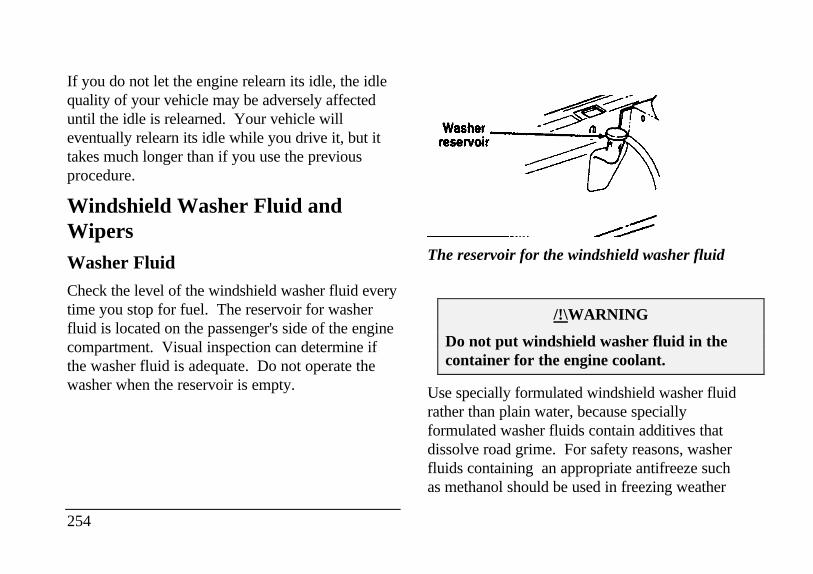
If you do not let the engine relearn its idle, the idlequality of your vehicle may be adversely affecteduntil the idle is relearned. Your vehicle willeventually relearn its idle while you drive it, but ittakes much longer than if you use the previousprocedure.
Windshield Washer Fluid andWipersWasher Fluid
Check the level of the windshield washer fluid everytime you stop for fuel. The reservoir for washerfluid is located on the passenger's side of the enginecompartment. Visual inspection can determine ifthe washer fluid is adequate. Do not operate thewasher when the reservoir is empty.
254
Washer reservoir
The reservoir for the windshield washer fluid
/!\WARNING
Do not put windshield washer fluid in thecontainer for the engine coolant.
Use specially formulated windshield washer fluidrather than plain water, because speciallyformulated washer fluids contain additives thatdissolve road grime. For safety reasons, washerfluids containing an appropriate antifreeze suchas methanol should be used in freezing weather
(temperatures below 32°F [0°C]). State or localregulations on Volatile Organic Compounds(VOC's) may restrict use of the most commonantifreeze, methanol. Washer fluids containing non-methanol antifreeze agents should be used only ifthey provide cold weather protection withoutdamaging the vehicle's paint finish, wiper blades,and windshield washer system.
Wiper Blades
Check the windshield wiper blades at least twice ayear. Also check them whenever they seem lesseffective than usual. Substances such as tree sapand some hot wax treatments used by commercialcar washes reduce the effectiveness of wiper blades.
If the blades do not wipe properly, clean both thewindshield and the wiper blades. Use undilutedwindshield washer solution or a mild detergent.Rinse thoroughly with clear water. Do not use fuel,kerosene, paint thinner, or other solvents to cleanyour wiper blades. These will damage your blades.
To make reaching the wiper blades easy, simply turnthe ignition to the ACC position and turn yourwipers on. Wait for them to reach a vertical positionand turn the ignition to the OFF position. Do notmove the wipers manually. Manually moving thewipers across the windshield may damage them.
Wiper blade replacement
If the wiper blades still do not work properly afteryou clean them, you may need to replace the wiperblade assembly or the blade element. When replacingthe wiper blade assembly, blade refill, or wiper armalways use a Motorcraft part or equivalent. Toreplace the blades, follow the instructions that comewith them.
TiresLook at your tires each time you fill your fuel tank.If one tire looks lower than the others, check thepressure in all of them. Always follow theseprecautions:
255
Keep your tires inflated to the recommendedpressures.
Stay within the recommended load limits (seeLoad limits in the Index).
Make sure the weight of your load is evenlydistributed.
If you do not take these precautions, your tires mayfail or go flat.
Ford Motor Company recommends obeying postedspeed limits.
/!\ WARNING
Driving too fast for conditions creates thepossibility of loss of vehicle control. Drivingat very high speeds for extended periods oftime may result in damage to vehiclecomponents.
256
At least once a month, check the pressure in all yourvehicle's tires, including the spare. Use an accuratetire pressure gauge. Check the tire pressure whentires are cold, after the vehicle has been parked for atleast one hour or has been driven less than 3 miles (5km). You can find proper cold pressure and loadlimits of recommended size tires on the SafetyCompliance Certification Label.
/!\ WARNING
Improperly inflated tires can affect vehiclehandling and can fail suddenly, possiblyresulting in loss of vehicle control.
Tire Rotation
Because your vehicle's front and rear tires performdifferent jobs, they often wear differently. To makesure your tires wear evenly and last longer, rotatethem as indicated in the following diagram.
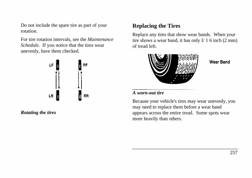
Do not include the spare tire as part of yourrotation.
For tire rotation intervals, see the MaintenanceSchedule. If you notice that the tires wearunevenly, have them checked.
Rotating the tires
Replacing the Tires
Replace any tires that show wear bands. When yourtire shows a wear band, it has only I/ 1 6 inch (2 mm)of tread left.
A worn-out tire Wear Band
Because your vehicle's tires may wear unevenly, youmay need to replace them before a wear bandappears across the entire tread. Some spots wearmore heavily than others.
257
/!\ WARNING
When replacing full size tires, never mixradial, bias-belted, or bias-type tires. Use onlythe tire sizes that are listed on the tirepressure decal. Make sure that all tires arethe same size, speed rating, and load-carryingcapacity. Use only the tire combinationsrecommended on the decal. If you do notfollow these precautions, your vehicle may notdrive properly and safely.
Tires that are larger or smaller than your vehicle'soriginal tires may also affect the accuracy of yourspeedometer.
258
Information About Tire Quality Grades
New vehicles are fitted with tires that have their TireQuality Grade (described below) molded into thetire's sidewall. These Tire Quality Grades aredetermined by standards that the United StatesDepartment of Transportation has set.
Tire Quality Grades apply to new pneumatic tires foruse on passenger cars. They do not apply to deeptread, winter-type snow tires, space-saver ortemporary use spare tires, tires with nominal rimdiameters of 10 to 12 inches or limited productiontires as defined in Title 49 Code of FederalRegulations Part 575.104(c)(2).
U.S. Department of Transportation - Tire qualitygrades: The U.S. Department of Transportationrequires Ford to give you the following informationabout tire grades exactly as the government haswritten it.
Treadwear
The treadwear grade is a comparative rating basedon the wear rate of the tire when tested undercontrolled conditions on a specified government testcourse. For example, a tire graded 150 would wearone and one-half (1 1/2) times as well on thegovernment course as a tire graded 100. Therelative performance of tires depends upon theactual conditions of their use, however, and maydepart significantly from the norm due to variationsin driving habits, service practices and differences inroad characteristics and climate.
Traction A B C
The traction grades, from highest to lowest, are A, B,and C, and they represent the tire's ability to stop onwet pavement as measured under controlledconditions on specified government test surfaces ofasphalt and concrete. A tire marked C may havepoor traction performance. Warning: The tractiongrade assigned to this tire is based on braking
(straightahead) traction tests and does not includecornering (turning) traction.
Temperature A B C
The temperature grades are A (the highest), B, andC, representing the tire's resistance to the generationof heat and its ability to dissipate heat when testedunder controlled conditions on a specified indoorlaboratory test wheel. Sustained high temperaturecan cause the material of the tire to degenerate andreduce tire life, and excessive temperature can leadto sudden tire failure. The grade C corresponds to alevel of performance which all passenger car tiresmust meet under the Federal Motor Vehicle SafetyStandard No. 109. Grades B and A represent higherlevels of performance on the laboratory test wheelthan the minimum required by law. Warning: Thetemperature grade for this tire is established for a tirethat is properly inflated and not overloaded.Excessive speed, underinflation, or excessive
259
loading, either separately or in combination, cancause heat buildup and possible tire failure.
Snow tires
The tires on your vehicle have all-weather treadsthat provide traction in rain or snow. However,during the winter months in some climates, you mayneed to use snow tires.
Use of tire chains is not recommended. The use oftire chains could result in damage to your vehicle.
/!\ WARNING
Snow tires must be the same size and gradeas the tires you Currently have on yourvehicle.
Cleaning the Wheels
Wash the wheels with the same detergent you useto wash your vehicle's body. Do not use acid-basedwheel cleaners, steel wool, abrasives, fuel, or strong
260
detergents. These substances will damage protectivecoatings. Use tar and road oil remover to removegrease and tar.
NOTE: Before going to a car wash, find out if thebrushes are abrasive.
If you have whitewall tires that are difficult to cleanwith regular detergent, use whitewall tire cleaner.Follow the directions on the container and rinse thetires with plenty of clean water.
Securitires (If equipped)Securitires are designed to allow you to continuedriving your Continental a limited number of mileswhen one of your vehicle's tires is at low or evenzero air pressure.
/!\ WARNING
Do not use aerosol tire inflator/sealer withSecuritires. Doing so may damage the tire'spressure sensor.
See Securitires in the Features chapter for moreinformation.
Automatic Transaxle FluidUnder normal circumstances, you do not need tocheck the fluid level of the transaxle, since yourvehicle does not use up transaxle fluid. Refer to theMaintenance Schedule and Record booklet forreplacement intervals. However, if the transaxle isnot working properly - for instance, the transaxlemay slip or shift slowly, or you may notice somesign of fluid leakage - the fluid level should bechecked.
NOTE: If the vehicle has been operated for anextended period at high speeds or in city trafficduring hot weather, or pulling a trailer, the vehicleshould be turned off for about 30 minutes to allowthe fluid to cool before checking.
Checking the Automatic Transaxle Fluid
With the vehicle on a level surface and the brake fullyapplied, start the engine and move the gear shiftselector through all of the gears allowing sufficienttime for each position to engage. Securely latch thegear shift selector in the P (Park) position. Fully setthe parking brake and leave the engine running.
Wipe off the dipstick cap and pull the dipstick out.Wipe the indicator end clean. Put the dipstick backinto the filler tube and make sure it is fully seated.Pull the dipstick out and read the fluid level.
NOTE: Your vehicle should not be driven untilsome fluid has been added if the fluid level is belowthe bottom dimple on the dipstick and the outsidetemperature is above 50°F (10°C). Add only enoughfluid to bring the level above the bottom hole.
261
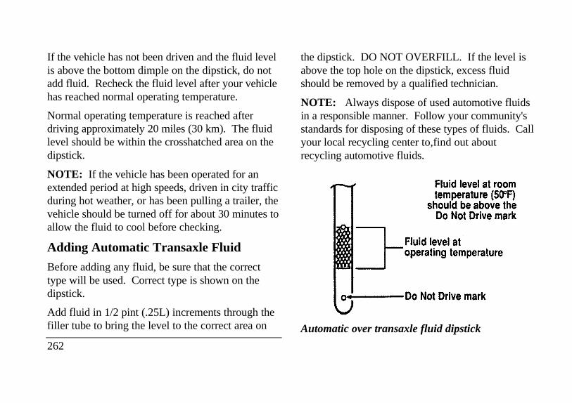
If the vehicle has not been driven and the fluid levelis above the bottom dimple on the dipstick, do notadd fluid. Recheck the fluid level after your vehiclehas reached normal operating temperature.
Normal operating temperature is reached afterdriving approximately 20 miles (30 km). The fluidlevel should be within the crosshatched area on thedipstick.
NOTE: If the vehicle has been operated for anextended period at high speeds, driven in city trafficduring hot weather, or has been pulling a trailer, thevehicle should be turned off for about 30 minutes toallow the fluid to cool before checking.
Adding Automatic Transaxle Fluid
Before adding any fluid, be sure that the correcttype will be used. Correct type is shown on thedipstick.
Add fluid in 1/2 pint (.25L) increments through thefiller tube to bring the level to the correct area on
262
the dipstick. DO NOT OVERFILL. If the level isabove the top hole on the dipstick, excess fluidshould be removed by a qualified technician.
NOTE: Always dispose of used automotive fluidsin a responsible manner. Follow your community'sstandards for disposing of these types of fluids. Callyour local recycling center to,find out aboutrecycling automotive fluids.
Automatic over transaxle fluid dipstick
Brake FluidUnder normal circumstances, your vehicle shouldnot use up brake fluid rapidly. However, expect thelevel of the brake fluid to slowly fall as you putmore mileage on your vehicle and the brake liningwears.
You should check the brake fluid at every scheduledengine oil change, but be sure to check it at leastonce a year. You can do this by looking at the fluidlevel in the plastic reservoir on the master cylinder.(See The Engine Type in this chapter to locate themaster cylinder.) The fluid level should be at or nearthe MAX mark.
/!\ WARNING
Brake fluid is toxic.
If brake fluid contacts eyes, flush eyes with runningwater for 15 minutes. Get medical attention if
irritation persists. If taken internally, drink water andinduce vomiting. Get medical attention immediately.
If the fluid is low, carefully clean and remove the capfrom the reservoir. Fill the reservoir to the MAXline with Ford High Performance DOT 3 Brake FluidC6AZ-19542-AA, C6AZ-19542-BA, or equivalentDOT 3 fluid meeting Ford specification ESA-M6C25-A.
/!\ WARNING
If you use a brake fluid that is not DOT 3, youwill cause permanent damage to your brakes.
Do not fill the reservoir above the MAX line.
If you find that the fluid level is excessively lowbelow the seam or ridge on the outside of the plasticreservoir - have the brake system inspected.
263
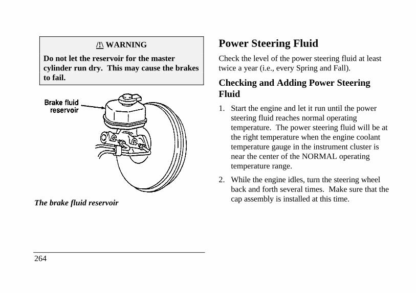
/!\ WARNING
Do not let the reservoir for the mastercylinder run dry. This may cause the brakesto fail.
The brake fluid reservoir
264
Power Steering FluidCheck the level of the power steering fluid at leasttwice a year (i.e., every Spring and Fall).
Checking and Adding Power SteeringFluid
1. Start the engine and let it run until the powersteering fluid reaches normal operatingtemperature. The power steering fluid will be atthe right temperature when the engine coolanttemperature gauge in the instrument cluster isnear the center of the NORMAL operatingtemperature range.
2. While the engine idles, turn the steering wheelback and forth several times. Make sure that thecap assembly is installed at this time.
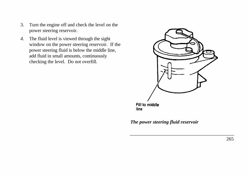
3. Turn the engine off and check the level on thepower steering reservoir.
4. The fluid level is viewed through the sightwindow on the power steering reservoir. If thepower steering fluid is below the middle line,add fluid in small amounts, continuouslychecking the level. Do not overfill.
The power steering fluid reservoir
265
Use only MERCON ATF power steering fluid.
If the power steering fluid is low, do not drive yourvehicle for a long period of time before adding fluid.This can damage the power steering pump.
FusesFuses (conventional and high current) protect yourvehicle's electrical system from overloading. Ifelectrical parts in your vehicle are not working, thesystem may have been overloaded and blown a fuse.Before you replace or repair any electrical parts,check the appropriate fuses (conventional and highcurrent).
266
The following charts tell you which fuses protecteach electrical part of your vehicle. If a fuse blows,all the parts of your vehicle that use that circuit willnot work.
Once you have determined which fuses to check,follow the procedures under Checking and replacingfuses in this chapter.
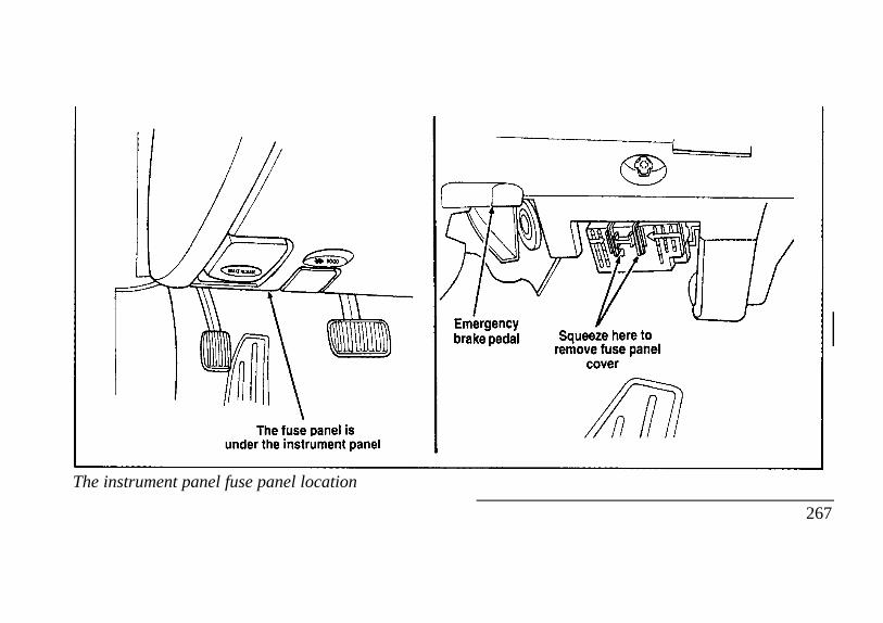
The instrument panel fuse panel location
Emergency
brake pedal Squeeze here to remove fuse panel
cover
267
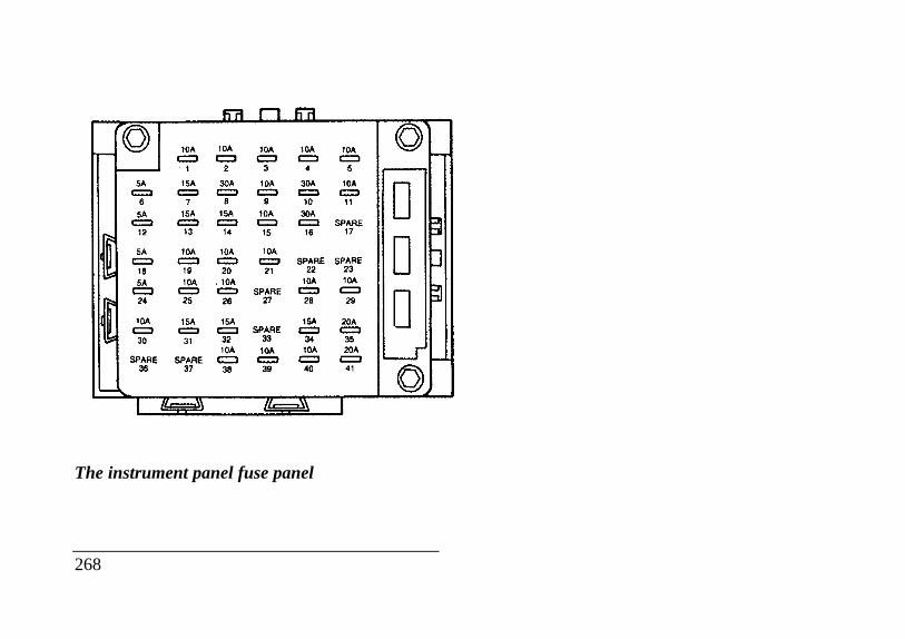
The instrument panel fuse panel
268
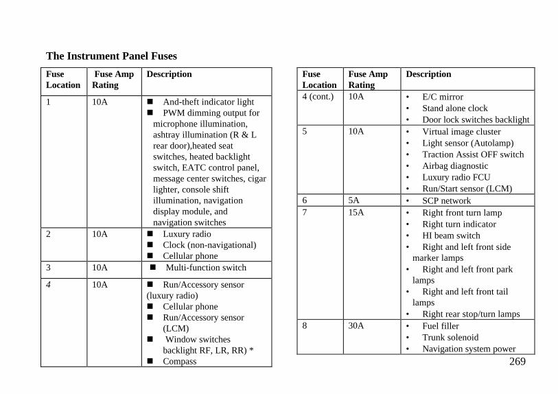
The Instrument Panel Fuses
FuseLocation
Fuse AmpRating
Description
1 10A n And-theft indicator lightn PWM dimming output for
microphone illumination,ashtray illumination (R & Lrear door),heated seatswitches, heated backlightswitch, EATC control panel,message center switches, cigarlighter, console shiftillumination, navigationdisplay module, andnavigation switches
2 10A n Luxury radion Clock (non-navigational)n Cellular phone
3 10A n Multi-function switch
4 10A n Run/Accessory sensor(luxury radio)n Cellular phonen Run/Accessory sensor
(LCM)n Window switches
backlight RF, LR, RR) *n Compass
FuseLocation
Fuse AmpRating
Description
4 (cont.) 10A • E/C mirror• Stand alone clock• Door lock switches backlight
5 10A • Virtual image cluster• Light sensor (Autolamp)• Traction Assist OFF switch• Airbag diagnostic• Luxury radio FCU• Run/Start sensor (LCM)
6 5A • SCP network7 15A • Right front turn lamp
• Right turn indicator• HI beam switch• Right and left front side
marker lamps• Right and left front park
lamps• Right and left front tail
lamps• Right rear stop/turn lamps
8 30A • Fuel filler• Trunk solenoid• Navigation system power
269
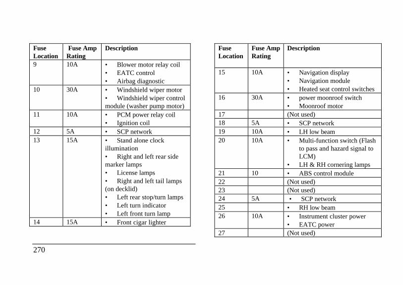
FuseLocation
Fuse AmpRating
Description
9 10A • Blower motor relay coil• EATC control• Airbag diagnostic
10 30A • Windshield wiper motor• Windshield wiper controlmodule (washer pump motor)
11 10A • PCM power relay coil• Ignition coil
12 5A • SCP network13 15A • Stand alone clock
illumination• Right and left rear sidemarker lamps• License lamps• Right and left tail lamps(on decklid)• Left rear stop/turn lamps• Left turn indicator• Left front turn lamp
14 15A • Front cigar lighter
270
FuseLocation
Fuse AmpRating
Description
15 10A • Navigation display• Navigation module• Heated seat control switches
16 30A • power moonroof switch• Moonroof motor
17 (Not used)18 5A • SCP network19 10A • LH low beam20 10A • Multi-function switch (Flash
to pass and hazard signal toLCM)
• LH & RH cornering lamps21 10 • ABS control module22 (Not used)23 (Not used)24 5A • SCP network25 • RH low beam26 10A • Instrument cluster power
• EATC power27 (Not used)
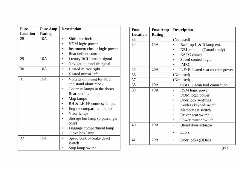
FuseLocation
Fuse AmpRating
Description
28 10A • Shift interlock• VDM logic power• Instrument cluster logic power• Rear defrost control
29 10A • Luxury RCU station signal• Navigation module signal
30 10A • Heated mirror right• Heated mirror left
31 15A • Voltage dimming for FCUand stand alone clock
• Courtesy lamps in the doorsRear reading lamps
• Map lamps• RH & LH I/P courtesy lamps• Engine compartment lamp• Visor lamps• Storage bin lamp (5 passenger
only)• Luggage compartment lamp• Glove box lamp
32 15A • Speed control brake deactswitch
• Stop lamp switch
FuseLocation
Fuse AmpRating
Description
33 (Not used)34 15A • Back-up L & R lamp ext.
• DRL module (Canada only)• EATC clutch• Speed control logic• IMRC
35 20A • L & R heated seat module power36 (Not used)37 (Not used)38 10A • OBD 11 scan tool connection39 10A • DSM logic power
• DDM logic power• Door lock switches• Keyless keypad switch• Memory set switch• Driver seat switch• Power mirror switch
40 10A • Blend door actuator
• LTPS
41 20A • Door locks (DDM)
271
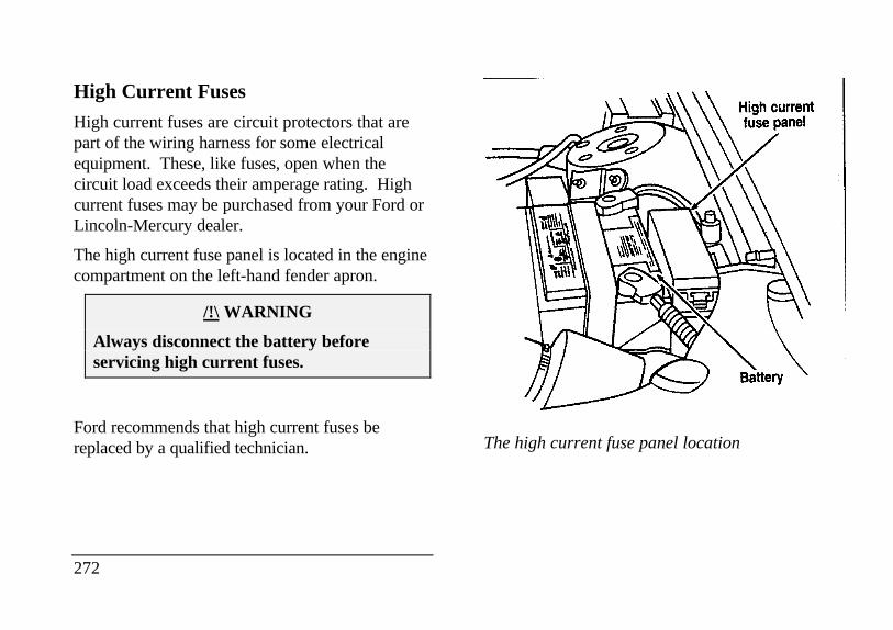
High Current Fuses
High current fuses are circuit protectors that arepart of the wiring harness for some electricalequipment. These, like fuses, open when thecircuit load exceeds their amperage rating. Highcurrent fuses may be purchased from your Ford orLincoln-Mercury dealer.
The high current fuse panel is located in the enginecompartment on the left-hand fender apron.
/!\ WARNING
Always disconnect the battery beforeservicing high current fuses.
Ford recommends that high current fuses bereplaced by a qualified technician.
272
The high current fuse panel location
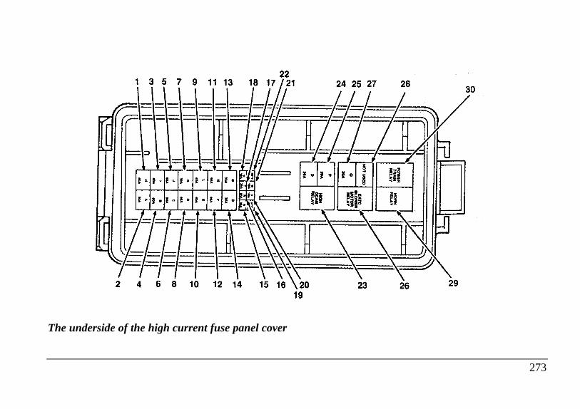
The underside of the high current fuse panel cover
273
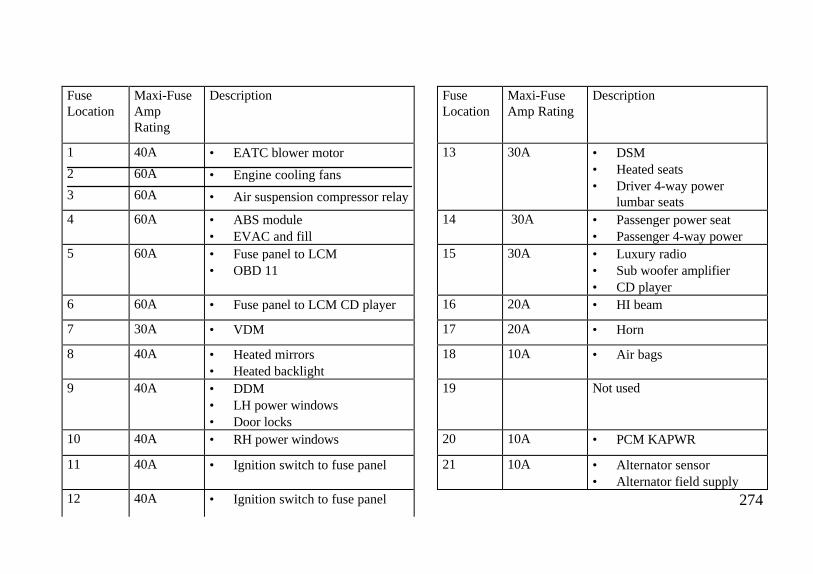
FuseLocation
Maxi-FuseAmpRating
Description FuseLocation
Maxi-FuseAmp Rating
Description
1
2
3
40A
60A
60A
• EATC blower motor
• Engine cooling fans
• Air suspension compressor relay
13 30A • DSM• Heated seats• Driver 4-way power
lumbar seats4 60A • ABS module
• EVAC and fill14 30A • Passenger power seat
• Passenger 4-way power5 60A • Fuse panel to LCM
• OBD 1115 30A • Luxury radio
• Sub woofer amplifier• CD player
6 60A • Fuse panel to LCM CD player 16 20A • HI beam
7 30A • VDM 17 20A • Horn
8 40A • Heated mirrors• Heated backlight
18 10A • Air bags
9 40A • DDM• LH power windows• Door locks
19 Not used
10 40A • RH power windows 20 10A • PCM KAPWR
11 40A • Ignition switch to fuse panel 21 10A • Alternator sensor• Alternator field supply
12 40A • Ignition switch to fuse panel 274
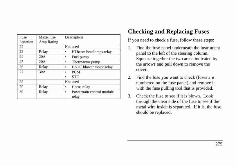
FuseLocation
Maxi-FuseAmp Rating
Description
22 Not used23 Relay • HI beam headlamps relay24 20A • Fuel pump25 20A • Thermactor pump26 Relay • EATC blower motor relay27 30A • PCM
• STC28 Not used29 Relay • Horns relay30 Relay • Powertrain control module
relay
Checking and Replacing FusesIf you need to check a fuse, follow these steps:
1. Find the fuse panel underneath the instrumentpanel to the left of the steering column.Squeeze together the two areas indicated bythe arrows and pull down to remove thecover.
2. Find the fuse you want to check (fuses arenumbered on the fuse panel) and remove itwith the fuse pulling tool that is provided.
3. Check the fuse to see if it is blown. Lookthrough the clear side of the fuse to see if themetal wire inside is separated. If it is, the fuseshould be replaced.
275
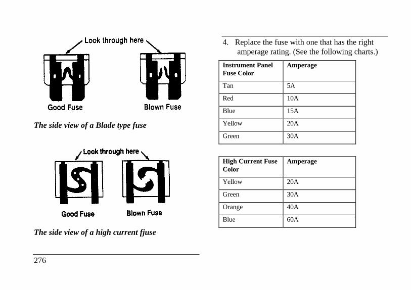
The side view of a Blade type fuse
The side view of a high current fjuse
276
4. Replace the fuse with one that has the rightamperage rating. (See the following charts.)
Instrument PanelFuse Color
Amperage
Tan 5A
Red 10A
Blue 15A
Yellow 20A
Green 30A
High Current FuseColor
Amperage
Yellow 20A
Green 30A
Orange 40A
Blue 60A
/!\ WARNING
Always replace a fuse with one that has thespecified amperage rating. Using a fuse witha higher amperage rating can cause severewire damage and could start a fire.
5. Align the edge of the cover with the edge ofthe fuse panel and push the cover up until itlatches.
Even after you replace a fuse, it will continue toblow if you do not find what caused the overload.If the fuse continues to blow, have your electricalsystem checked.
Lights and Bulb ReplacementIt is a good idea to check the operation of thefollowing lights ftequently:
headlamps
high-mount brakelamp
tail lamps
brakelamps
hazard flasher
turn signals
side markers
license plate lamp
The alignment of your headlamps should bechecked if:
oncoming motorists frequently signal you toturn off your vehicle's high beams when you donot have the high beams on
the headlamps do not seem to give you enoughlight to see clearly at night
277
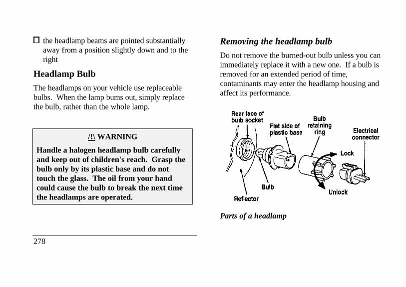
the headlamp beams are pointed substantiallyaway from a position slightly down and to theright
Headlamp Bulb
The headlamps on your vehicle use replaceablebulbs. When the lamp bums out, simply replacethe bulb, rather than the whole lamp.
/!\ WARNING
Handle a halogen headlamp bulb carefullyand keep out of children's reach. Grasp thebulb only by its plastic base and do nottouch the glass. The oil from your handcould cause the bulb to break the next timethe headlamps are operated.
278
Removing the headlamp bulb
Do not remove the burned-out bulb unless you canimmediately replace it with a new one. If a bulb isremoved for an extended period of time,contaminants may enter the headlamp housing andaffect its performance.Rear face of bulb socket Reflector Flat side of plastic base bulb retaining ring
Parts of a headlamp
Electrical connector Lock Unlock
1. Make sure that the headlamp switch is in theOFF position.
2. Lift the hood and remove the plastic sightshield covering the back of the headlamps bylifting up on the rear corners to release thevelcro attachments. Lift the shield and pulltowards the windshield.
3. At the back of the headlamp, pull up on thetwo right angle brackets to release theheadlamp assembly from the vehicle.
4. Carefully pull the headlamp assembly awayfrom the vehicle to expose the back of thebulb and wiring connector.
5. Remove the electrical connector from the bulbby grasping the wire with a quick pullrearward.
6. Remove the retaining ring by turning it 1/8 ofa turn to free it from the socket. Then slidethe ring off the plastic base of the bad bulb.Keep the ring. You must use it again to holdthe new bulb in place.
7. Carefully remove the bulb assembly from itssocket by gently pulling it rearward withoutturning.
Installing the headlamp bulb
1. With the flat side of the bulb's plastic basefacing upward, insert the glass end of the bulbinto the socket. You may need to turn thebulb left or right to line up the grooves in theplastic base with the tabs in the socket. Whenthe grooves are aligned, push the bulb into thesocket until the plastic base contacts the rearof the socket.
279
2. Slip the bulb retaining ring over the plastic baseuntil it contacts the rear of the socket. Lock thering into the socket by rotating it clockwiseuntil you feel a "stop".
3. Push the electrical connector into the rear ofthe plastic base until it snaps, locking it intoposition
4. Carefully position the headlamp assembly ontothe vehicle making sure the alignment pins areinserted into the proper holes
5. Hold the headlamp assembly snugly against thevehicle and push down on the right anglebrackets to lock the lamp into position.
6. Install the plastic sight shield.
7. Turn the headlamps on and make sure that theywork properly. If the headlamp was correctlyaligned before you changed the bulb, youshould not need to align it again..
280
Aiming Headlamps
Your vehicle is equipped with a Vehicle HeadlampAim Device (VHAD) on each headlamp body.Each headlamp may be properly aimed in thehorizontal direction (left/right) and the verticalposition (up/down).
NOTE: A non-zero bubble reading does notnecessarily indicate out-of-aim headlamps. If yourvehicle is not positioned on a level surface, theslope will be included in the level indicator.Therefore, vertical headlamp adjustment should be
Tools required: One 4mm socket and ratchet.
The Horizontal aim must be adjusted first.
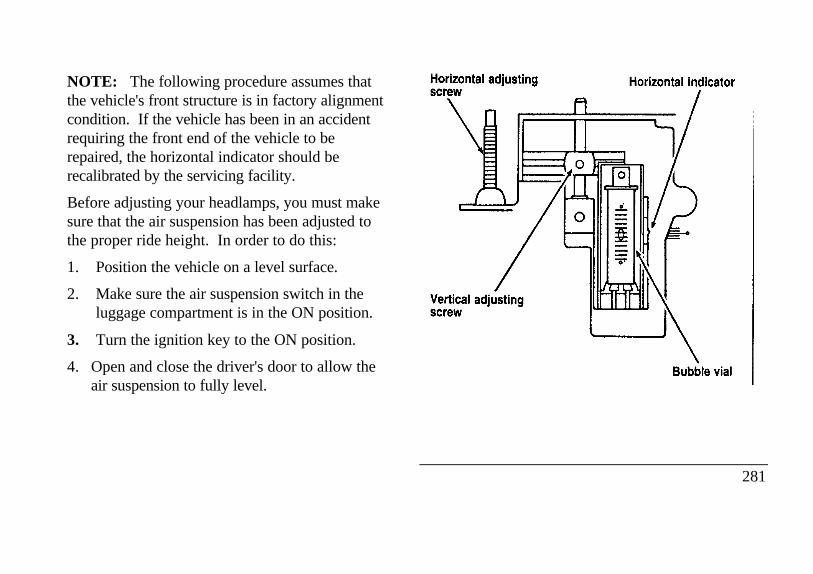
NOTE: The following procedure assumes thatthe vehicle's front structure is in factory alignmentcondition. If the vehicle has been in an accidentrequiring the front end of the vehicle to berepaired, the horizontal indicator should berecalibrated by the servicing facility.
Before adjusting your headlamps, you must makesure that the air suspension has been adjusted tothe proper ride height. In order to do this:
1. Position the vehicle on a level surface.
2. Make sure the air suspension switch in theluggage compartment is in the ON position.
3. Turn the ignition key to the ON position.
4. Open and close the driver's door to allow theair suspension to fully level. Hori
zontal adjusting screw Vertical adjusting screw Horizontal indicator Bubble vial
281
Horizontal aim adjustment
1. Open the hood and lift the front end coverfrom its velcro attachments. Locate thehorizontal level indicator and adjustmentscrew.
2. Use a 4mm socket and ratchet to turn thehorizontal adjusting screw until the horizontalindicator is in line with the "0" reference.
282
Vertical aim adjustment
NOTE: The numbers shown on the vial indicatebeam direction in degrees up or down.
1. Locate the vertical level indicator and adjustmentscrew.
2. Use a 4mm socket and ratchet to turn the verticaladjustment screw until the bubble in thehorizontal level indicator is centered in the vial.
3. Replace the front end cover and close the hood.
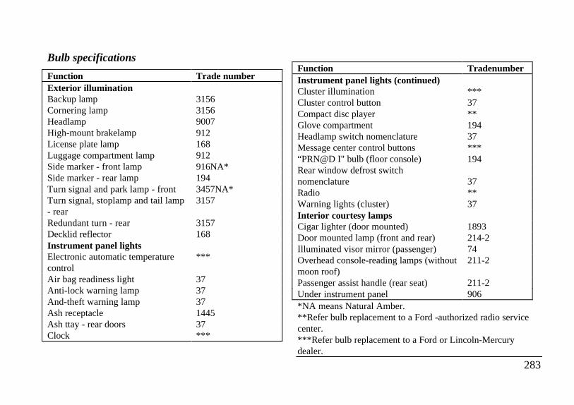
Bulb specifications
Function Trade numberExterior illuminationBackup lamp 3156Cornering lamp 3156Headlamp 9007High-mount brakelamp 912License plate lamp 168Luggage compartment lamp 912Side marker - front lamp 916NA*Side marker - rear lamp 194Turn signal and park lamp - front 3457NA*Turn signal, stoplamp and tail lamp- rear
3157
Redundant turn - rear 3157Decklid reflector 168Instrument panel lightsElectronic automatic temperaturecontrol
***
Air bag readiness light 37Anti-lock warning lamp 37And-theft warning lamp 37Ash receptacle 1445Ash ttay - rear doors 37Clock ***
Function TradenumberInstrument panel lights (continued)Cluster illumination ***Cluster control button 37Compact disc player **Glove compartment 194Headlamp switch nomenclature 37Message center control buttons ***“PRN@D I" bulb (floor console) 194Rear window defrost switchnomenclature 37Radio **Warning lights (cluster) 37Interior courtesy lampsCigar lighter (door mounted) 1893Door mounted lamp (front and rear) 214-2Illuminated visor mirror (passenger) 74Overhead console-reading lamps (withoutmoon roof)
211-2
Passenger assist handle (rear seat) 211-2Under instrument panel 906*NA means Natural Amber.**Refer bulb replacement to a Ford -authorized radio servicecenter.***Refer bulb replacement to a Ford or Lincoln-Mercurydealer.
283
Emission Control SystemYour vehicle is equipped with three (3) catalyticconverters which are used to enable your vehicle tocomply with applicable exhaust emissionsrequirements.
/!\ WARNING
Exhaust leaks may result in the entry ofharmful and potentially lethal fumes into thepassenger compartment. Under extremeconditions excessive exhaust temperaturescould damage the fuel system, the interiorfloor covering, or other vehicle components,possibly causing a fire.
To make sure that the catalytic converters and theother emissions control parts continue to workproperly:
Use only premium unleaded fuel.
284
Avoid running out of fuel.
Do not turn off the ignition while your vehicle ismoving, especially at high speeds.
Do not push start your vehicle.
Have the services listed in the MaintenanceSchedule and Record booklet performed accordingto the specified schedule. The scheduledmaintenance services are required because they areconsidered essential to the life and performance ofyour vehicle and to its emissions system.
In general, maintenance, replacement, or service ofthe emissions control devices or systems in your newFord Motor Company vehicle or engine may beperformed at your expense by any automotive repairestablishment or individual using automotive partsequivalent to those which your vehicle or engine wasoriginally equipped.
Ford strongly recommends the use of genuine Fordreplacement parts. If other than Ford orMotorcraft parts or Ford authorizedremanufactured parts are used for maintenancereplacements or for the service of componentsaffecting emission control, such non-Ford partsshould be equivalent to genuine Ford MotorCompany parts in performance and durability. It isthe owner's responsibility to determine theequivalency of such parts. Please consult yourwarranty booklet for complete warrantyinformation.
/!\ WARNING
Do not park, idle, or drive your vehicle in drygrass or other dry ground cover. Theemission system heats up the enginecompartment and exhaust system, which canstart a fire.
Watch for fluid leaks, strange odors, smoke, lossof oil pressure, the charge warning light, the check
engine light, or the temperature warning light. Thesesometimes indicate that the emission system is notworking properly.
Do not make any unauthorized changes to yourvehicle or engine. Changes that cause more unburnedfuel to reach the exhaust system can increase thetemperature of the engine or exhaust system.
By law, anyone who manufactures, repairs, services,sells, leases, trades vehicles, or supervises a fleet ofvehicles is not permitted to intentionally remove anemission control device or prevent it from working.In some of the United States and in Canada, vehicleowners may be liable if their emission control deviceis removed or is prevented from working.
Do not drive your vehicle if it does not operateproperly. See your dealer if the engine runs on formore than five seconds after you shut it off or if itmisfires, surges, stalls, or backfires.
285
Information about your vehicle's emission controlsystem is on the Vehicle Emission ControlInformation decal located on or near the engine.This decal identifies engine displacement and givessome tune-up specifications.
Readiness for Inspection/MaintenanceTesting
In some localities it may become a legal requirementto pass an Inspection/Maintenance (I/M) test of theOn-Board Diagnostic (OBD) II system. If thevehicle's powertrain system or its battery has justbeen serviced, the OBD II system is reset to a notready for I/M testing condition. To prepare for I/Mtesting, the law specifies a "need for additionalmixed city and highway driving to complete thecheck" of the OBD II system. As soon as all of theOBD II system checks are successfully completed,the OBD II system is set to the ready condition. Theamount of driving required to reach the readycondition varies with individual driving patterns. Tocomplete this requirement in the
minimum amount of time, refer to the OBD II DriveCycle defined below. If the vehicle owner cannot ordoes not want to do the additional driving required bylaw, a service center can perform this drive cycle as itwould any other type of repair work.
OBD II Drive Cycle
The following steps must be run in the order shown.If steps 2 through 9 are interrupted, repeat thepreceeding step. Any safe driving mode is acceptablebetween steps.
Always drive vehicle in a safe manner according totraffic conditions and obey all traffic laws.
1. Start engine and drive until engine has reachednormal operating temperature.
2. Idle vehicle for at least 80 seconds, thenaccelerate at part throttle to near 45 mph (72 km/h).
286
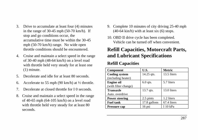
3. Drive to accumulate at least four (4) minutesin the range of 30-45 mph (50-70 km/h). Ifstop and go conditions occur, theaccumulative time must be within the 30-45mph (50-70 km/h) range. No wide openthrottle conditions should be encountered.
4. Cruise and maintain a select speed in the rangeof 30-40 mph (48-64 km/h) on a level roadwith throttle held very steady for at least one(1) minute.
5. Decelerate and idle for at least 80 seconds.
6. Accelerate to 55 mph (90 km/h) at ½ throttle.
7. Decelerate at closed throttle for I 0 seconds.
8. Cruise and maintain a select speed in the rangeof 40-65 mph (64-105 km/h) on a level roadwith throttle held very steady for at least 80seconds.
9. Complete 10 minutes of city driving 25-40 mph(40-64 kin/h) with at least six (6) stops.
10. OBD II drive cycle has been completed.Vehicle can be turned off when convenient.
Refill Capacities, Motorcraft Parts,and Lubricant SpecificationsRefill CapacitiesComponent U.S. MetricCooling system(including heater)
14.25 qts. 13.5 liters
Engine oil(with filter change)
6.0 qts. 5.7 liters
TransaxleAuto. overdrive
13.7 qts. 13.0 liters
Power steering 2.5 pints 1.2 litersFuel tank 17.8 gallons 67.4 litersPressure cap 16 psi I 10 kPa
287
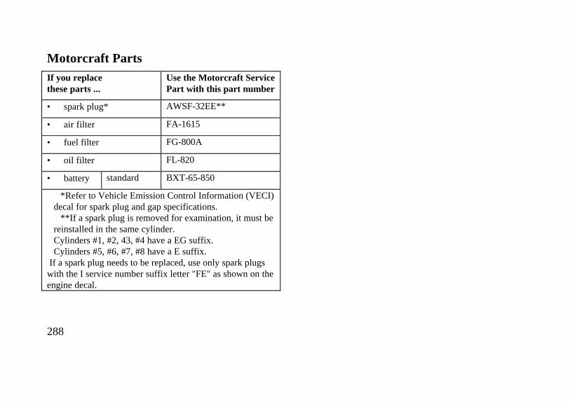
Motorcraft PartsIf you replacethese parts ...
Use the Motorcraft ServicePart with this part number
• spark plug* AWSF-32EE**
• air filter FA-1615
• fuel filter FG-800A
• oil filter FL-820
• battery standard BXT-65-850
*Refer to Vehicle Emission Control Information (VECI)decal for spark plug and gap specifications.
**If a spark plug is removed for examination, it must bereinstalled in the same cylinder.Cylinders #1, #2, 43, #4 have a EG suffix.Cylinders #5, #6, #7, #8 have a E suffix.
If a spark plug needs to be replaced, use only spark plugswith the I service number suffix letter "FE" as shown on theengine decal.
288
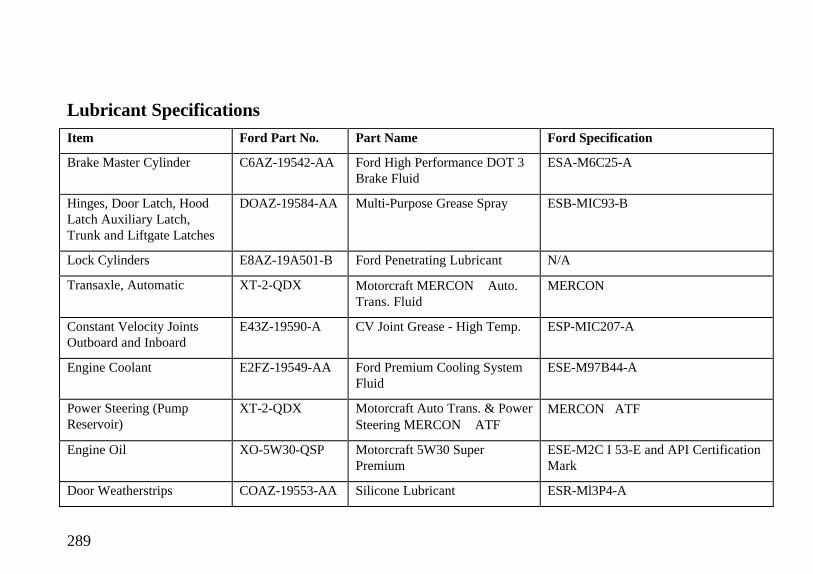
Lubricant SpecificationsItem Ford Part No. Part Name Ford Specification
Brake Master Cylinder C6AZ-19542-AA Ford High Performance DOT 3Brake Fluid
ESA-M6C25-A
Hinges, Door Latch, HoodLatch Auxiliary Latch,Trunk and Liftgate Latches
DOAZ-19584-AA Multi-Purpose Grease Spray ESB-MIC93-B
Lock Cylinders E8AZ-19A501-B Ford Penetrating Lubricant N/A
Transaxle, Automatic XT-2-QDX Motorcraft MERCON Auto.Trans. Fluid
MERCON
Constant Velocity JointsOutboard and Inboard
E43Z-19590-A CV Joint Grease - High Temp. ESP-MIC207-A
Engine Coolant E2FZ-19549-AA Ford Premium Cooling SystemFluid
ESE-M97B44-A
Power Steering (PumpReservoir)
XT-2-QDX Motorcraft Auto Trans. & PowerSteering MERCON ATF
MERCONATF
Engine Oil XO-5W30-QSP Motorcraft 5W30 SuperPremium
ESE-M2C I 53-E and API CertificationMark
Door Weatherstrips COAZ-19553-AA Silicone Lubricant ESR-Ml3P4-A
289
NOTE: Rear axle lube quantities must bereplaced every 100,000 miles (160,000 km) or ifthe axle has been submerged in water. Otherwise,the lube should not be checked or changed unless aleak is suspected or repair required.
Vehicle StorageMaintenance Tips
If you plan on storing your vehicle for an extendedperiod of time (60 days or more), refer to thefollowing maintenance recommendations to ensureyour vehicle stays in good operating condition.
General
Store all vehicles in a dry, ventilated place.
Protect from sunlight, if possible.
If vehicles are stored outside, they requireregular maintenance to protect against rustand damage.
290
Body
Wash vehicle thoroughly to remove dirt, grease,oil, tar or mud from exterior surfaces, rearwheel housing and underside of front fenders.
Periodically wash vehicles stored in exposedlocations.
Touch-up raw or primed metal to prevent rust.
Cover chrome and stainless steel parts with athick coat of auto wax to prevent discoloration.Re-wax as necessary when the vehicle iswashed.
Lubricate all hood, door and trunk lid hingesand latches with a light grade oil.
Cover interior soft trim to prevent fading.
Keep all rubber parts free from oil and solvents.
Engine
Start engine every 15 days. Run at fast idleuntil it reaches normal operating temperature.
With your foot on the brake, shift through allthe gears while the engine is running.
Fuel system
Fill fuel tank with high-quahty, premiumunleaded fuel until the first automatic shutoff ofthe fuel pump nozzle.
NOTE: During extended periods of vehiclestorage (60 days or more), fuel may deterioratedue to oxidation. This can damage rubber andother polymers in the fuel system and may alsoclog small orifices.
Ford Gas Stabilizer should be added wheneveractual or expected storage periods exceed 60 days.Follow the instructions on the label. The vehicleshould then be operated at idle speed to circulatethe additive throughout the fuel system.
A volatile corrosion inhibitor added to the fuelsystem will protect the fuel system's inner surfacesfrom corrosion. Follow the instructions packagedwith the product.
Cooling system
Protect against freezing temperatures.
291
Battery
Check and recharge as necessary.
Keep connections clean and covered with a lightcoat of grease.
If storing your vehicle for more than 30 dayswithout recharging the battery, disconnect thebattery cables to ensure battery charge ismaintained for quick starting. NOTE: If batterycables are disconnected, it will be necessary toreset any memory features (eg. radio presets).
Brakes
Make sure brakes and parking brake are fullyreleased.
292
Tires
Maintain recommended air pressures.
Miscellaneous
Make sure all linkages, cables, levers andclevis pins under vehicle are covered with grease toprevent rust.
Move vehicles at least 25 feet (8 m) every 15days to lubricate working parts and preventcorrosion.
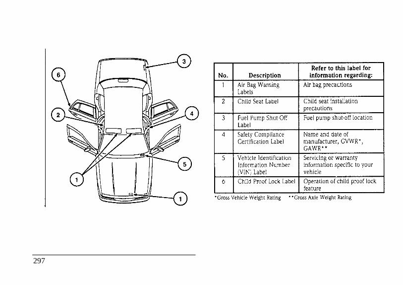
labels Air Bag warning Child Seat Label Child seat installation precautions Fuel Pump Shut-Off Safety Compliance Certification Label manufacturer, GVWR*
GAWR** Vehicle Identification Servicing or warranty Information Number Child Proof Lock Gross Vehicle
Weight Rating **Gross Axle Weight Rating
297
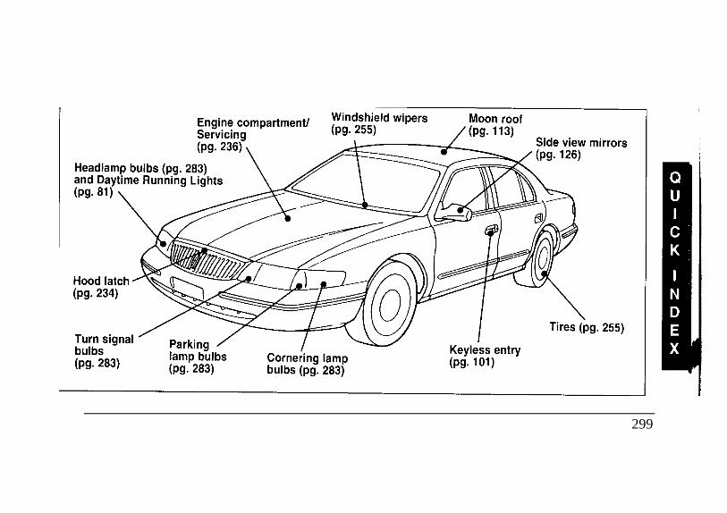
Engine compartment/ Servicing Windshield wipers Headlamp bulbs and Daytime Running Lights Hood latch Turn signal bulbs Parking lamp bulbsCornering lamp bulbs Moon roof Keyless entry Side view mirrors Tires
299
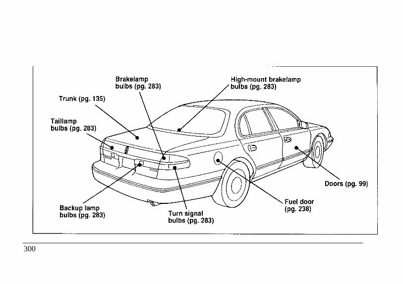
Trunk Taillamp bulbs Backup lamp bulbs Brakelamp bulbs Turn signal bulbs High-mount brakelamp bulbs Fuel doorDoors
300
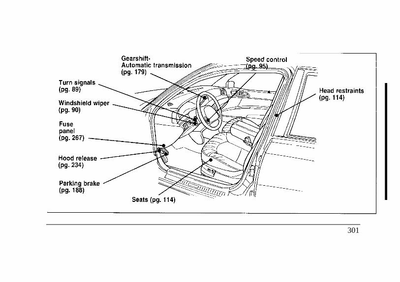
Turn signals Windshield wiper Fuse panel Hood release Parking brake Gearshift- Automatic transmission Seats Speed control Head restraints
301
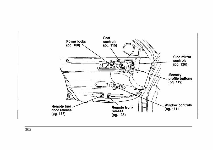
Remote fuel door release Seat controls Remote trunk release Side mirror controls Memory profile buttons power locks window controls
302
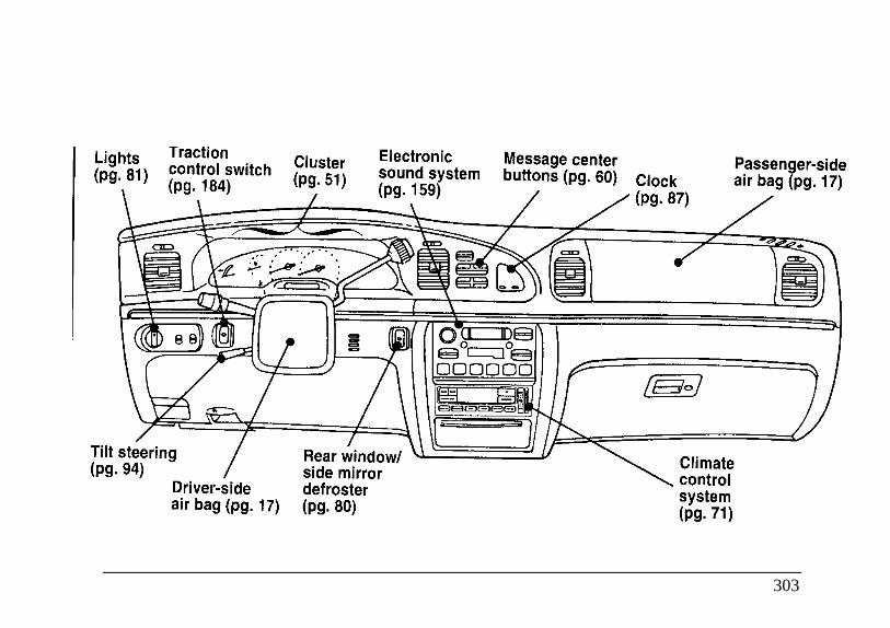
Lights Traction control Tilt steering Driver-side air bag Lights Traction Cluster Electronic sound system Tilt steering Rear window/ side mirrorDriver-side defroster air bag Message center buttons Clock Climate control system Passenger-side air bag
303
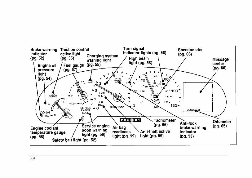
Brake warning indicator Engine oil pressure light Traction control active light Charging system warning light Fuel gauge ANTITHEFT active light Service engine soon warning light Engine coolant temperature gauge Safety belt light Turn signal indicator lights High beam lightAir bag readiness light Speedometer Tachometer Anti-theft active light Anti-lock brake warning indicator Message center Odometer
304
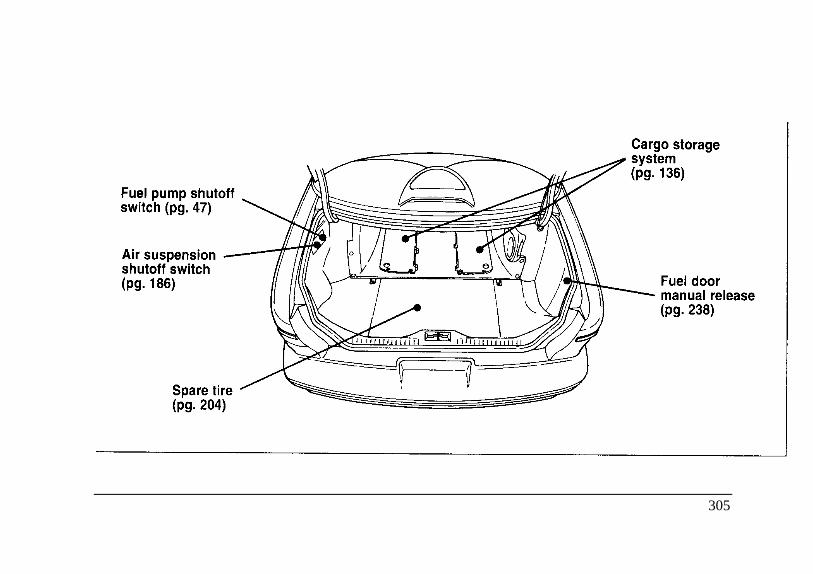
Fuel pump shutoff switch Air suspension shutoff switch Spare tire Cargo storage system Fuel door manual release
305
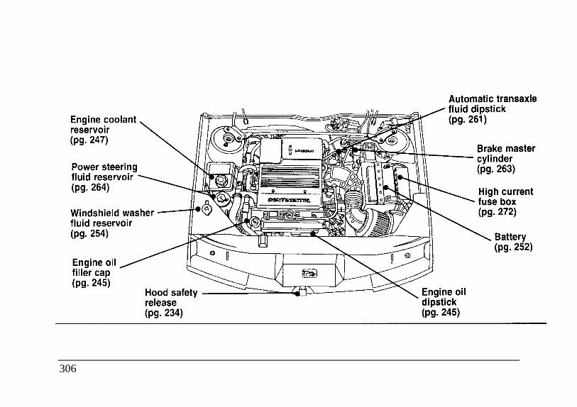
Engine coolant reservoir Power steering fluid reservoir Windshield washer fluid reservoir Automatic transaxlefluid dipstick Brake master cylinder
Engine oil filler cap Hood safety release Engine oil dipstick High current fuse box Battery
306
IndexA Air conditioning, electronic automatic
ABS warning light........................................ temperature control system ..................71(see Anti-lock brake system) .................. 53 Air suspension
Accessory position on the ignition ............ 41 air leveling disabled warning, messageAccident damage.................................... 232 center ................................................62Additives, engine oil ............................... 245 description.......................................186Air bag supplemental restraint system........... Alarm, activating remote personal.........106
description........................................... 17 Alcohol, in fuel.....................................241disposal ............................................... 25 Antenna, radioindicator light ...................................... 59 (see Electronic sound system)........165operation ............................................. 20 Antifreeze (see Engine coolant)......247proper seating...................................... 19 Anti-lock brake system (ABS) .................tone generator ..................................... 24 description.....................................187wearing safety belts ............................. 18 noise..............................................187
Air cleaner filter ........................................... warning light ...................................53location ............................................. 237 Anti-theft lug nuts and key ...................209specifications ..................................... 288
307
Anti-theft system........................................ B ..............................arming the system............................ 109 Backing up .............................................182description....................................... 108 Basic vehicle warranty ................................5disarming an untriggered system ...... 110 Battery .........................................................disarming a triggered system ............ 111 acid, treating emergencies ..................200triggering ......................................... 111 battery saver ......................................108warning light......................................59 charging system warning light ..............55
Assistance (see Customer assistance).... 213 disconnecting .....................................253Audio system ............................................. how to service....................................252
(see Electronic sound system) ............ 159 jumping a disabled battery ..................199Automatic transaxle.................................... maintenance-free ................................252
fluid, adding..................................... 262 proper disposal, recycling...................253fluid, checking ................................. 261 replacement, specifications .................288fluid, refill capacities ........................ 287 when storing your vehicle...................292fluid, specification............................ 289 Brake fluid.............................................................. brake warning light...............................52.............................................................. checking and adding...........................263.............................................................. description .........................................263.............................................................. specifications......................................289.............................................................. Brakes ........................................................................................................................ adjustment ..............................................187.............................................................. anti-lock.............................................187
308
applying the brakes......................... 187brake warning light...........................52fluid, checking and adding .............. 263fluid, refill capacities....................... 287fluid, specifications ......................... 289new brake linings................................6noise............................................... 188parking........................................... 188trailer ............................................. 197when storing your vehicle ............... 292
Brake-shift interlock............................. 180Break-in period ........................................6Bulbs, replacing.................................... 277
headlamps........................................ 278C
Canada, customer assistance................. 219Canadian Motor Vehicle Arbitration Plan
(CAMVAP) ....................................... 220Capacities for refilling fluids ................. 287Carbon monoxide in exhaust...................49Car seats for children
(see Child safety seats) .........................27
Catalytic converter 284CD player (see Electronic sound system) . 169Chains, tires 260Changing a tire 204Charging system warning light 55Childproof locks 99Child safety restraints 25
child safety belts 38child safety seats 27
Child safety seatsattaching with tether straps 38
tether anchorage hardware 38Chime
headlamps on 58key in ignition 42safety belt 52
Cleaning your vehiclechrome and aluminum parts 8exterior 7exterior lamps 83fabric 118headlamps 83
309
Cleaning your vehicle (continued)............... Console, description ...............................133instrument panel ................................69 Controls, mirrors ....................................127mirrors ..................................... 126,127 Coolant (see Engine coolant) ........................plastic parts .........................................8 checking and adding...........................247polishing..............................................7 drain and flush....................................251rustproofing.........................................8 preparing for storage..........................291safety belts.........................................17 refill capacities ...................................287tail lamps ...........................................83 specifications......................................289upholstery and interior trim.............. 118 temperature gauge................................66washing ...............................................7 Cooling fan.............................................233wheels ............................................. 260 D..................................
Climate control system ............................... Dashboard (see Instrument panel) .............69air conditioning..................................71 Daytime running light system ....................81electronic automatic temperature ........... Defrost, windshield...................................78
control ............................................71 Dipstick........................................................heating...............................................71 engine oil ...........................................246
Clock .....................................................87 power steering fluid............................264Cold engine starting ...............................44 Dispute Settlement Board .......................214Compact disc player (see Electronic ........... Doors .......................................................99
sound system) .................................... 169 lubricant specifications .......................289Compass .............................................. 139 ................................................................
310
Driving under special conditions Emission control systembad weather 191 catalytic converter................................ 284heavy load 192 emissions warranty............................... 284high water 192 Engineslippery roads 191 does not start .................................... 45towing a trailer 194 fuel injected engine, starting .............. 43
fuel pump shut-off switch.................. 47E preparing to start .............................. 43
Electrical system refill capacities .................................. 287fuses 275 service points .................................... 237operating when the engine is off 41 starting ............................................. 44
Electronic sound system starting after a collision ..................... 47accessory delay 165 storing your vehicle........................... 291antenna 165 Engine block heater.................................. 46radio reception 176 Engine coolant
tuning the radio.......................................161 checking and adding ................ 247warranty and service information.............178 disposal 232, 250, 262
Emergencies, roadside......................................................... drain and flush ......................... 251battery acid spills................................... 199 preparing for storage ............... 291jump-starting 199 ................ refill capacities......................... 287towing 211 ................ refill procedure ........................ 251
Emergency brake (parking brake) ................. 188 specifications ........................... 289
311
Engine coolant temperature gauge,. Fluid refill capacities.............................287description .............................. 66 Ford Dispute Settlement Board ............214
Engine fan...................................... 233 Ford Extended Service Plan......................6Engine oil....................................... Ford Motor Company of Canada ..........219
"break-in" oils............................ 6 Ford of Canada Customer...........................changing oil and oil filter............ 247 Assistance Centre...............................219checking and adding .................. 245 Foreign registration ..............................221dipstick...................................... 246 French owner guides, how to obtain .........3disposal 232, 250, 262 . Fuel............................................................engine oil pressure warning light 54 calculating fuel economy..................243filter, specifications.................... 288 capacity ...........................................287refill capacities........................... 28- choosing the right fuel......................240specifications ............................. 289 comparisons with EPA fuel economy .....synthetic oil ............................... 245 estimates .......................................243viscosity .................................... 245 filling your vehicle with fuel .............238
Exhaust fumes................................ 49 filter, specifications ..........................288Extended Service Plan, Ford........... 6 fuel gauge..........................................67
F.................... running out of fuel ...........................242Flashers, hazard.............................. 92 safety information relating to..................Flashing the lights........................... 90 automotive fuels ............................241Flat tire .......................................... 204 storing your vehicle..........................291...................................................... treating emergencies ........................241
312
Fuel cap ............................................... odometer .........................................65removing .......................................... 238 speedometer.....................................66replacing........................................... 239 tachometer .......................................66
Fuel filter, specifications............................... 288 GAWR (Gross Axle Weight Rating)Fuel gauge ........................................... 67 calculating......................................193Fuel pump shut-off switch, starting after a .......... definition........................................192
collision.................................................. 47 location .................................192Fuse panels ............................................... Gearshift
engine compartment.......................... 272 column-mounted ...................................181instrument panel ............................... 267 positions .............................................179
Fuses ............................................... shift-lock .............................................180charts .................................... 269 GVVVR (Gross Vehicle Weight
Rating)checking and replacing...................... 275 calculating .............................193 G .............. definition .............................................192
Gas cap (see Fuel cap).................................. 238 location .............................................192Gas mileage (see Fuel economy)................... 243 HGasohol . ......................................... 241 Hazard flashers........................................92Gasoline (see Fuel)....................................... 238 HeadlampsGauges, Mechanical ........................................... aiming.......................................277,280
engine coolant temperature gauge....... 66 autolamp system ............................... 83fuel gauge ...................................... 67 checking alignment.......................... 277
313
Headlamps (continued)................................. I .............................cleaning ............................................... 83 Idle.............................................................daytime running lights.......................... 81 relearning.........................................253flashing................................................ 90 speed .................................................45high beam............................................ 90 Ignition ......................................................replacing bulbs................................... 277 chime.................................................42turning on and off ................................ 82 positions of the ignition......................41warning chime ..................................... 58 removing the key ...............................42
Head restraints ....................................... 114 Infant seats (see Safety seats) .................27Heated mirrors ....................................... 127 Instrument panel, location of components .70Heating ........................................................ Interval wipers........................................91
electronic automatic temperature ............. ..................................................................control system................................... 71 J.............................
High beams, indicator light ....................... 58 Jack, operation .....................................207Hood............................................................ Jump-starting your vehicle..........................
latch location ...............................234,235 attaching cables................................201lubrication specifications.................... 289 disconnecting cables.........................203release lever....................................... 234 K ...............................working under the hood..................... 233 Keyless entry system...................................
Horn ........................................................ 93 locking and unlocking doors ............102.................................................................... programming entry code ..................103
314
Keys............................................................. charging system...............................55key in ignition chime............................ 42 engine oil pressure...........................54positions of the ignition........................ 41 high beam........................................58removing from the ignition................... 42 oil pressure......................................54stuck in lock position........................... 42 safety belt ........................................52
L ................................. service engine soon..........................56Lamps.......................................................... turn signal indicator .........................56
autolamp delay system ......................... 83 Load limitschecking ............................................ 277 GAWR ............................................192................................................................ GVVVR ..........................................192daytime running light system................ 81 trailer towing ...................................194flashing the lamps ................................ 90 Lubricant specifications ........................289hazard flashers..................................... 92 Luggage compartment..........................135headlamps............................................ 82 Lug nuts, anti-theft ...............................209high beams........................................... 90replacing bulbs................................... 277 .......................... Mtrailer ................................................. 197 Maintenance (see Servicing) .................231
Lane change indicator (see Turn signal).... 89 Map pockets.........................................134Lights, warning and indicator ....................... Methanol in fuel ...................................241
air bag ................................................. 59 Mileage, calculating fuel economy ........243anti-theft.............................................. 59 Mirrorsbrake ................................................... 52 automatic dimming rearview mirror..125
315
Mirrors (continued)........ Pheated........................ 127 Panic alarm feature, remote entry................rearview .................... 125 system................................................106
Moon roof...................... 113 Parking brake .............................................Motorcraft parts............. 288 operation .........................................188...................................... N warning light......................................52National Highway Traffic . Safety Parts (see Motorcraft Parts)..................288
Administration ............... 218 Phone, cellular........................................88...................................... Power features ............................................................................... 0 moon roof........................................113
Odometer, description .... 65 seats ................................................115Oil filter ......................... 289 windows ..........................................111Oil (see Engine oil)......... 244 Power steering ...........................................Oil viscosity ................... 245 driving with power steering..............185On-board diagnostic (OBD II) system .... 286 fluid, checking and adding ................264Overdrive............................................... 183 fluid, refill capacity ...........................287.................................................................... fluid, specifications...........................289.................................................................... Pressure alert system ........................142
316
RRadio (see Electronic sound systems) ... 159Rearview mirror ................................... 125Refill capacities for fluids ..................... 287Remote entry system
arming and disarming the anti-theftsystem........................................... 106
locking/unlocking doors................... 105opening the trunk............................. 106panic alarm ...................................... 106replacement/additional transmitters .. 107replacing the batteries ...................... 106
RESCU system .................................... 144Restraints, safety (see Safety restraints)
adult ....................................................9child ..................................................25head ................................................ 114infant .................................................25
Roadside emergencies .......................... 199Rotating the tires.................................. 256
SSafe driving tips....................................190Safety belts (see Safety restraints)............ 9Safety chains, when towing a trailer ......196Safety Compliance Certification Label ..192Safety defects, reporting .......................218Safety information relating to automotive
fuels................................................241Safety restraints
adjusting the safety belts................12,16cleaning the safety belts.....................17extension assembly............................16for children .......................................25for infants .........................................25lap and shoulder belts........................11maintenance......................................17replacement ......................................17warning light and chime ....................52
Safety seats for childrenand air bags...................................19,27attaching with tether straps.................38
317
Seats .......................................................... removing the spare tire.......................205adjusting the seats, power ................ 115 temporary spare .................................204child safety seats................................27 Spark plugs, specifications ......................288head restraints ................................. 114 Specification chart, lubricants .................289
Securitire ............................................. 141 Speed control ...............................................Service concerns .................................. 213 accelerating..........................................97Servicing your vehicle, precautions when.... canceling a set speed ............................98
servicing ............................................ 233 resetting...............................................97Shift-lock system.................................. 180 resuming a set speed ............................98Shift positions (see Gearshift)............... 181 turning off............................................98Shoulder and lap belts ................................ when towing a trailer..........................198
(see Safety restraints)...........................11 Speedometer.............................................66Side mirrors ............................................... Starting your vehicle.....................................
adjusting.......................................... 126 preparing to start your vehicle ..............43heated . . ......................... 127 starting a cold engine ...........................44
Sliding moon roof (see Moon roof) ...... 113 starting after a collision ........................47Snow tires and chains ........................... 260 starting a warm engine .........................45Spare tire ................................................... Steering, power ......................................185
changing the tire .............................. 206 Steering wheel ..............................................finding the spare .............................. 205 horn .....................................................93.............................................................. tilting ...................................................94
318
Storage compartmentscenter console.................................. 133map pockets .................................... 134
Storing your vehicle ............................. 290Sun visor.............................................. 128Supplemental air bag readiness light .......59Supplemental Restraint System (SRS) ....17
TTachometer ........................................... 66Tail lamps, cleaning............................... 83Tether anchor installation
(see Child restraints) ........................... 38Tilt steering wheel................................. 94Tires
changing........................................... 204checking the pressure................. 255,256cleaning ............................................ 260replacing........................................... 257rotating............................................. 256snow tires and chains ........................ 260
storing your vehicle .......................292tire grades .....................................258treadwear ...............................257,259wear bands ....................................257
Towing a trailer (see Trailer towing).....194Towing your vehicle .............................211Trailer towing
calculating maximum trailer weight ..194safety chains.....................................196tips...................................................198trailer brakes ....................................197trailer lamps .....................................197
Transaxlefluid, checking and adding
(automatic) . . ................................261fluid, refill capacities ........................287lubricant specifications .....................289
Trunk, using the remote entrysystem to open ...................................106
319
Tune-up specifications (VECI)............. 285 W .......................................Turn signal................................................. Warm engine, starting............................... 45
indicator lights................................... 56 Warning chimes............................................lever.................................................. 89 headlamps on....................................... 58............................................................. key in ignition ...................................... 42
u................................ safety belt ............................................ 52Used engine oil, disposal .........232,250,262 Warranties, radio.................................... 178Universal transmitter .... 130 Warranty Information Booklet.................... 5.................................... Washer fluid.................................... V reservoir ............................................ 254Variable interval wipers 91 windshield 254VECI (Vehicle Emission Control ................. Weight limits (GAWR, GVVVR) ......... 192
Information) decal ................................286 WheelsVehicle loading ............................................ anti-theft lugnuts ............................. 209
automatic transaxles ...........................193 cleaning........................................... 260calculating the load.............................193 inspection and maintenance.............. 255
Vehicle storage .......................................290 Windows.............................................. 111Ventilating your vehicle ............................... power windows, operating............... 111
(see Climate control) ..............................77Viscosity (see Engine oil)........................245Visor (see Sun visor)...............................128
320
Windshield washer fluid and wiperschecking and adding fluid.....................254checking and replacing wiper blades . . 255operation ...............................................90reservoir ..............................................254
321
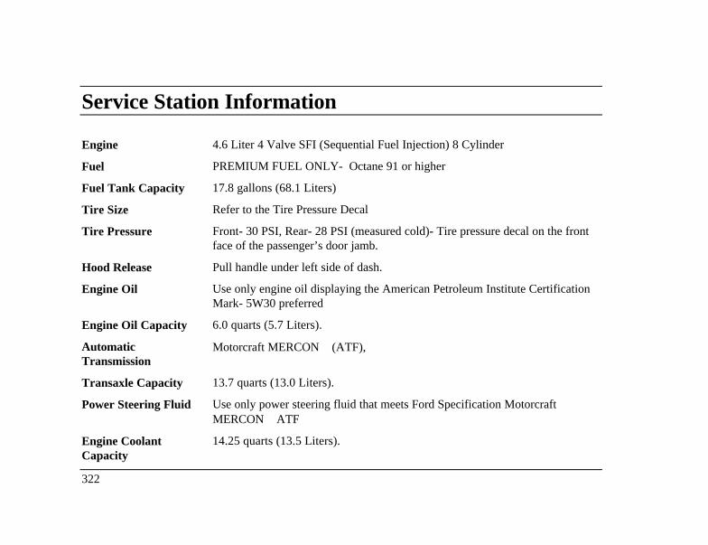
Service Station Information
Engine 4.6 Liter 4 Valve SFI (Sequential Fuel Injection) 8 Cylinder
Fuel PREMIUM FUEL ONLY- Octane 91 or higher
Fuel Tank Capacity 17.8 gallons (68.1 Liters)
Tire Size Refer to the Tire Pressure Decal
Tire Pressure Front- 30 PSI, Rear- 28 PSI (measured cold)- Tire pressure decal on the frontface of the passenger’s door jamb.
Hood Release Pull handle under left side of dash.
Engine Oil Use only engine oil displaying the American Petroleum Institute CertificationMark- 5W30 preferred
Engine Oil Capacity 6.0 quarts (5.7 Liters).
AutomaticTransmission
Motorcraft MERCON (ATF),
Transaxle Capacity 13.7 quarts (13.0 Liters).
Power Steering Fluid Use only power steering fluid that meets Ford Specification MotorcraftMERCON ATF
Engine CoolantCapacity
14.25 quarts (13.5 Liters).
322