95715279 practical guide for electrical wiring
TRANSCRIPT
Practical Guide to Inspection, Testing and Certification ofElectrical Installations

This page intentionally left blank
Practical Guide toInspection, Testingand Certification ofElectrical InstallationsConforms to IEE WiringRegulations/BS 7671/Part P ofBuilding Regulations
Christopher Kitcher
AMSTERDAM • BOSTON • HEIDELBERG • LONDON • NEW YORK • OXFORD
PARIS • SAN DIEGO • SAN FRANCISCO • SINGAPORE • SYDNEY • TOKYO
Newnes is an imprint of Elsevier

Newnes is an imprint of ElsevierLinacre House, Jordan Hill, Oxford OX2 8DP, UK30 Corporate Drive, Suite 400, Burlington, MA 01803, USA
First edition 2008
Copyright © 2008, Christopher Kitcher. Published by Elsevier Ltd. All rights reserved
The right of Christopher Kitcher to be identified as the author of this work has been asserted inaccordance with the Copyright, Designs and Patents Act 1988
No part of this publication may be reproduced, stored in a retrieval system or transmitted in any form or by any means electronic, mechanical, photocopying, recording or otherwise without the prior written permission of the publisher
Permissions may be sought directly from Elsevier’s Science & Technology Rights Department in Oxford, UK: phone (�44) (0) 1865 843830; fax (�44) (0) 1865 853333; email: [email protected]. Alternatively you can submit your request online by visiting the Elsevier web site at http://elsevier.com/locate/permissions, and selectingObtaining permission to use Elsevier material
NoticeNo responsibility is assumed by the publisher for any injury and/or damage to persons or property as a matter of products liability, negligence or otherwise, or from any use or operation ofany methods, products, instructions or ideas contained in the material herein.
DisclaimerThis book draws on many sources. Some are facts, some hypotheses, some opinions. Most –including many of my own statements – are mixtures. Even ‘facts’ are unavoidably selective and can rarely be guaranteed. Despite careful checking, neither I nor my colleagues or publisherscan accept responsibility for any errors, misinformation or unsuitable advice. This also applies to opinions – particularly on issues affecting health and safety. As any recommendations mustbalance complex, often opposing, factors, not everyone will reach the same conclusions. In this – as indeed in every issue this book touches on – every reader must make up her or hismind, for which they alone must be responsible.
I offer the best advice I am capable of, but every circumstance is different. Anyone who acts onthis advice must make their own evaluation, and adapt it to their particular circumstances.
British Library Cataloguing in Publication DataA catalogue record for this book is available from the British Library
Library of Congress Cataloging-in-Publication DataA catalog record for this book is available from the Library of Congress
ISBN: 978-0-7506-8449-1
Printed and bound in Great Britain
08 09 10 11 12 10 9 8 7 6 5 4 3 2 1
For information on all Newnes publicationsvisit our website at www.Elsevier.com
Contents
Preface . . . . . . . . . . . . . . . . . . . . . . . . . . . . . . . . . . . . . . . . . . . . . . . . . . . . . ixForeword . . . . . . . . . . . . . . . . . . . . . . . . . . . . . . . . . . . . . . . . . . . . . . . . . . . .xiAcknowledgements . . . . . . . . . . . . . . . . . . . . . . . . . . . . . . . . . . . . . . . . . . .xiii
1. Inspection and testing of electrical installations . . . . . . . . . . . . . . . . . . .1Why inspect and test? . . . . . . . . . . . . . . . . . . . . . . . . . . . . . . . . . . . . . . .1
Section 1. Design, Installation, Inspection and Testing . . . . . . . . . . . . .2Section 2. Extensions, Material alterations and material changes of use . . . . . . . . . . . . . . . . . . . . . . . . . . . . . . . . . . . . . . . . . . .3Section 3. Information about other legislation . . . . . . . . . . . . . . . . . . .3
Compliance with Building Regulations Part P . . . . . . . . . . . . . . . . . . . . . .4Earthing and bonding to comply with Part P . . . . . . . . . . . . . . . . . . . . . . .5Registered domestic installer . . . . . . . . . . . . . . . . . . . . . . . . . . . . . . . . . .5Unregistered competent person . . . . . . . . . . . . . . . . . . . . . . . . . . . . . . . .6DIY installer . . . . . . . . . . . . . . . . . . . . . . . . . . . . . . . . . . . . . . . . . . . . . . .6Summary . . . . . . . . . . . . . . . . . . . . . . . . . . . . . . . . . . . . . . . . . . . . . . . . .7
2. Types of certification required for inspecting and testing of installations . . . . . . . . . . . . . . . . . . . . . . . . . . . . . . . . . . . . . . . . . . . . .9Certification required for domestic installations (Part P) . . . . . . . . . . . . . .9
Minor Electrical Installation Works Certificate . . . . . . . . . . . . . . . . . . .9Part P, Domestic Electrical Installation Certificate . . . . . . . . . . . . . . . . .9Periodic inspection, testing and reporting . . . . . . . . . . . . . . . . . . . . .10
Certification required for the inspecting and testing of installations other than domestic . . . . . . . . . . . . . . . . . . . . . . . . . . . . . .10
Minor Electrical Installation Works Certificate . . . . . . . . . . . . . . . . . .11Electrical Installation Certificate . . . . . . . . . . . . . . . . . . . . . . . . . . . . .11Initial verification inspection . . . . . . . . . . . . . . . . . . . . . . . . . . . . . . .11Initial verification testing . . . . . . . . . . . . . . . . . . . . . . . . . . . . . . . . . .13Periodic inspection report . . . . . . . . . . . . . . . . . . . . . . . . . . . . . . . . .13Periodic inspection . . . . . . . . . . . . . . . . . . . . . . . . . . . . . . . . . . . . . .14Three phase circuit/systems . . . . . . . . . . . . . . . . . . . . . . . . . . . . . . . .21Periodic testing . . . . . . . . . . . . . . . . . . . . . . . . . . . . . . . . . . . . . . . . .21Voltage drop in conductors . . . . . . . . . . . . . . . . . . . . . . . . . . . . . . . .23
3. Testing of electrical installations . . . . . . . . . . . . . . . . . . . . . . . . . . . . . .25Safe isolation . . . . . . . . . . . . . . . . . . . . . . . . . . . . . . . . . . . . . . . . . . . . .25
Isolation procedure . . . . . . . . . . . . . . . . . . . . . . . . . . . . . . . . . . . . . .28Testing for continuity of protective conductors . . . . . . . . . . . . . . . . . . . .31
Main equipotential bonding . . . . . . . . . . . . . . . . . . . . . . . . . . . . . . . .31Continuity of supplementary bonding . . . . . . . . . . . . . . . . . . . . . . . .35Continuity of circuit protective conductors . . . . . . . . . . . . . . . . . . . .40Method one . . . . . . . . . . . . . . . . . . . . . . . . . . . . . . . . . . . . . . . . . . . .40Method two . . . . . . . . . . . . . . . . . . . . . . . . . . . . . . . . . . . . . . . . . . . .42
Ring final circuit test . . . . . . . . . . . . . . . . . . . . . . . . . . . . . . . . . . . . . . .42Complete ring circuit . . . . . . . . . . . . . . . . . . . . . . . . . . . . . . . . . . . . .42Broken ring circuit . . . . . . . . . . . . . . . . . . . . . . . . . . . . . . . . . . . . . . .43Interconnections . . . . . . . . . . . . . . . . . . . . . . . . . . . . . . . . . . . . . . . .43Polarity . . . . . . . . . . . . . . . . . . . . . . . . . . . . . . . . . . . . . . . . . . . . . . .45Performing the test . . . . . . . . . . . . . . . . . . . . . . . . . . . . . . . . . . . . . . .45
Insulation resistance test . . . . . . . . . . . . . . . . . . . . . . . . . . . . . . . . . . . .51Testing a whole installation . . . . . . . . . . . . . . . . . . . . . . . . . . . . . . . .52Testing of individual circuits . . . . . . . . . . . . . . . . . . . . . . . . . . . . . . .57Testing of 3 phase installations . . . . . . . . . . . . . . . . . . . . . . . . . . . . . .59
Testing of site applied insulation . . . . . . . . . . . . . . . . . . . . . . . . . . . . . .62Polarity tests . . . . . . . . . . . . . . . . . . . . . . . . . . . . . . . . . . . . . . . . . . . . . .62
Polarity test on a radial circuit such as a cooker or immersion heater circuit . . . . . . . . . . . . . . . . . . . . . . . . . . . . . . . . . .63Polarity test on a lighting circuit . . . . . . . . . . . . . . . . . . . . . . . . . . . . .64Live polarity test . . . . . . . . . . . . . . . . . . . . . . . . . . . . . . . . . . . . . . . .67
Earth electrode testing . . . . . . . . . . . . . . . . . . . . . . . . . . . . . . . . . . . . . .70Earth fault loop impedance tester . . . . . . . . . . . . . . . . . . . . . . . . . . . .70Measurement using an earth electrode test instrument . . . . . . . . . . . .72
Earth fault loop impedance Ze . . . . . . . . . . . . . . . . . . . . . . . . . . . . . . . .73Earth fault path for a TT system . . . . . . . . . . . . . . . . . . . . . . . . . . . . .74Earth fault path for a TNS system . . . . . . . . . . . . . . . . . . . . . . . . . . . .75Earth fault path for a TNCS system . . . . . . . . . . . . . . . . . . . . . . . . . . .76
Circuit earth fault loop impedance . . . . . . . . . . . . . . . . . . . . . . . . . . . . .79Method one . . . . . . . . . . . . . . . . . . . . . . . . . . . . . . . . . . . . . . . . . . . .82Method two . . . . . . . . . . . . . . . . . . . . . . . . . . . . . . . . . . . . . . . . . . . .83
Prospective fault current test . . . . . . . . . . . . . . . . . . . . . . . . . . . . . . . . .92Functional testing . . . . . . . . . . . . . . . . . . . . . . . . . . . . . . . . . . . . . . . . .98
Residual current device (RCD) . . . . . . . . . . . . . . . . . . . . . . . . . . . . . .98Types of RCD . . . . . . . . . . . . . . . . . . . . . . . . . . . . . . . . . . . . . . . . . . .98RCDs and supply systems . . . . . . . . . . . . . . . . . . . . . . . . . . . . . . . .101Testing of RCDs . . . . . . . . . . . . . . . . . . . . . . . . . . . . . . . . . . . . . . . .103
Contents
vi
4. Completion of test certificates . . . . . . . . . . . . . . . . . . . . . . . . . . . . . .109Minor Electrical Installation Works Certificate . . . . . . . . . . . . . . . . . . .109Electrical Installation Certificate . . . . . . . . . . . . . . . . . . . . . . . . . . . . . .115Schedule of Circuit Details and Test Results . . . . . . . . . . . . . . . . . . . . .121Schedule of Items Inspected . . . . . . . . . . . . . . . . . . . . . . . . . . . . . . . . .127
Method of protection against electric shock . . . . . . . . . . . . . . . . . . .130Cables and conductors . . . . . . . . . . . . . . . . . . . . . . . . . . . . . . . . . .133General . . . . . . . . . . . . . . . . . . . . . . . . . . . . . . . . . . . . . . . . . . . . . .134
Periodic Inspection Report . . . . . . . . . . . . . . . . . . . . . . . . . . . . . . . . . .136Completing the form . . . . . . . . . . . . . . . . . . . . . . . . . . . . . . . . . . . .137Summary of the inspection . . . . . . . . . . . . . . . . . . . . . . . . . . . . . . .141Overall assessment . . . . . . . . . . . . . . . . . . . . . . . . . . . . . . . . . . . . .141Supply characteristics, earthing and bonding arrangements . . . . . . .143Characteristics of the supply protective device . . . . . . . . . . . . . . . . .143Means of earthing . . . . . . . . . . . . . . . . . . . . . . . . . . . . . . . . . . . . . .143Main protective conductors . . . . . . . . . . . . . . . . . . . . . . . . . . . . . . .144
5. Safety in electrical testing . . . . . . . . . . . . . . . . . . . . . . . . . . . . . . . . . .149Correct selection of protective devices . . . . . . . . . . . . . . . . . . . . . . . . .149Test equipment . . . . . . . . . . . . . . . . . . . . . . . . . . . . . . . . . . . . . . . . . .156
Instruments required . . . . . . . . . . . . . . . . . . . . . . . . . . . . . . . . . . . .157Calibration of test instruments . . . . . . . . . . . . . . . . . . . . . . . . . . . . .158
Electric shock . . . . . . . . . . . . . . . . . . . . . . . . . . . . . . . . . . . . . . . . . . . .160Testing transformers . . . . . . . . . . . . . . . . . . . . . . . . . . . . . . . . . . . . . . .164Testing a 3 phase induction motor . . . . . . . . . . . . . . . . . . . . . . . . . . . .164
Appendix A IP codes . . . . . . . . . . . . . . . . . . . . . . . . . . . . . . . . . . . . . . . .167Appendix B Exercises . . . . . . . . . . . . . . . . . . . . . . . . . . . . . . . . . . . . . . . .169Appendix C Questions . . . . . . . . . . . . . . . . . . . . . . . . . . . . . . . . . . . . . . .175Appendix D Answers to Exercises . . . . . . . . . . . . . . . . . . . . . . . . . . . . . .181Appendix E Answers to Questions . . . . . . . . . . . . . . . . . . . . . . . . . . . . . .197Appendix F Useful information . . . . . . . . . . . . . . . . . . . . . . . . . . . . . . . .205
Index . . . . . . . . . . . . . . . . . . . . . . . . . . . . . . . . . . . . . . . . . . . . . . . . . . . . .209
Contents
vii

This page intentionally left blank
Preface
Part P of the Building Regulations came into effect on the 1st of January 2005.This part of the Building Regulations requires that all electrical work carriedout in domestic installations now has to be certificated. For work places, theElectricity at Work Regulations 1989 require that they provide a safe and wellmaintained electrical system. Certification and well kept records are a perfectway to confirm that every effort has been made to ensure that the system is,and remains safe.
I have written this book to assist electricians of all levels in carrying out theinspecting, testing and certification of all types of electrical installations. It willalso be invaluable to City and Guilds 2330 level 2 and 3 students, electriciansstudying for City and Guilds 2391 parts 101 and 102 and all tradesmen whoare required to comply with Building Regulation part P.
Step by step guidance and advice is given on how to carry out a detailed visualinspection during initial verifications, periodic inspections and certification.
Text and colour photographs of real, not simulated installations, are used toshow the correct test instruments. Step by step instructions for how to carryout each test safely using different types of instruments are given along withan explanation as to why the tests are required.
In some photographs safety signs have been omitted for clarity. All test leadsare to GS 38 where required. Some comments within this book are my ownview and have been included to add a common sense approach to inspectingand testing.
Interpretation of test results is a vital part of the testing process. The correctselection and use of tables from BS 7671 and the On Site Guide are shownclearly. Any calculations required for correct interpretation or for the passingof exams are set out very simply. An in depth knowledge of maths is notrequired.
I have included questions and example scenarios, along with answers andcompleted documentation. These will assist electricians at all levels whetherthey need to pass an exam or complete the certification.
During my time lecturing I have been asked many questions by students whohave become frustrated by being unable to reference definitive answers.Within this book I have tried to explain clearly and simply many of thesedifficult questions.
Chris Kitcher
Preface
x

Foreword
Christopher Kitcher is a very experienced electrician and teacher. I haveworked with him for the last 11 years in both the college environment and ‘onsite’. We are both examiners and also work for the City of Guilds on the 2391qualification. Christopher now mainly works in education as well as writingbooks; this is his second book in the electrical installation sector, his first wasthe successful and very practical update to the WATKINS series.
Christopher’s track-record speaks for it self; his work was instrumental in hiscollege gaining the status of Centre of Vocational Excellence this is anaccolade for training providers who gain a grade 1 or 2 during the jointOFSTED/ALI inspection.
Practical is again the keyword, as the book takes the reader from why to how invery clear steps. There are not only clear explanations, but photographs toguide the reader.
Whether an experienced electrician testing large industrial or commercialinstallations or a domestic installer altering or adding to installations, Chrishas got it covered for you, generally using a language that installers use andnot just technological terms that most installers find it difficult to understand.After all, we are electricians and not English language teachers, aren’t we?
This new and exciting practical guide will support candidates who are lookingto take exams such as the City and Guilds testing and inspection 2391 or 2,the EAL VRQ level 2 Domestic installer and the NIC Part P course.
Gerry Papworth B.A. (Hons), MIET, Eng. Tech, LCGIManaging Director of Steve Willis Training (Portsmouth) Ltd
Chief examiner for City & Guilds 2391

This page intentionally left blank
Acknowledgements
Writing this book has been a challenge which I have thoroughly enjoyed. Ithas been made a pleasurable experience because of the encouragement andgenerosity of many people and organisations. Particular thanks go to:
For the use of test equipment:Phil Smith of KewtechPeter Halloway of Megger UK.
All at NIC certification for their help and assistance in allowing thereproduction of certificates and reports.
My granddaughter Heather Bates whose computer skills and patience savedthe day on many occasions!
My colleagues at Central Sussex College for their valuable input, support andexpertise:Dave ChewterJason HartLee AshbyAndy Hay-EllisJon KnightSimon Nobbs
Brian Robinson for taking the photographs.
Finally, a special thanks is due to Central Sussex College for allowing me touse their facilities and equipment.
Chris Kitcher

This page intentionally left blank
3
Why inspect and test?
The Electricity at Work Regulations 1989 is a statutory document; it is a legalrequirement that statutory regulations are complied with. Not to comply is acriminal offence and could result in a heavy fine and even imprisonment inextreme cases.
These regulations are required to ensure that places of work provide a safe,well-maintained electrical system. A simple way to provide this is to ensurethat newly installed circuits and existing installations are tested on a regularbasis. Electrical test certificates are used to record what has been done andconfirm that the installation meets the required standard.
The British standard for electrical installations is BS 7671, the requirementfor electrical installations. Within this standard, Regulation 711-01-01 statesthat “every installation shall, during erection and on completion before beingput into service be inspected and tested to verify, so far as reasonablypracticable, that the requirements of the regulations have been met”.
Regulation 731-01-02 states that “where required, periodic inspection andtesting of every electrical installation shall be carried out in accordance withthe requirements of Chapter 73”.
Document P of the Building Regulations 2000 for Electrical Safety came intoeffect on 1 January 2005 and was amended in April 2006.
Inspection and testing ofelectrical installations1
The purpose of this document is to ensure electrical safety in domesticelectrical installations.
Section 1. Design, Installation, Inspection and Testing
This section of Part P is broken down into sub-sections.
General
This states that electrical work must comply with the Electricity at WorkRegulations 1989 and that any installation or alteration to the main supplymust be agreed with the electricity distributor.
Design and installation
This tells us that the work should comply with BS 7671 electrical wiringregulations.
Protection against flooding
The distributor must install the supply cut out in a safe place and take intoaccount the risk of flooding. Compliance with The Electrical Safety, Qualityand Continuity Regulations 2002 is required.
Accessibility
Part M of the building regulations must be complied with.
Inspection and testing before taking into service
This area is covered in detail throughout this book, it reminds us that theinstallation must be inspected and tested to verify that it is safe to put intoservice.
BS 7671 Installation certificates
This tells us that compliance with Part P can be demonstrated by the issue of acorrect Electrical Installation Certificate and also what the certificate shouldcover. This is addressed later in this book.
Building regulation compliance certificates or notices for notifiable work
This tells us that the completion certificates issued by the local authorities,etc. are not the same as the certificates that comply with BS 7671. Thecompletion certificates do not only cover Part P, but also shows compliancewith all building regulations associated with the work which has been carried out.
Inspection and Testing of Electrical Installations
2
Certification of notifiable work
This is covered in detail throughout this book.
Inspection and testing of non-notifiable work
This tells us that, even if the work is non-notifiable, it must be carried out tocomply with BS 7671 and that certificates should be completed for the work.
Provision of information
Information should be provided for the installation to assist with the correctoperation and maintenance. This information would comprise of certification,labels, instruction and plans.
Section 2. Extensions, Material alterations and material changes of use
This section is covered throughout this book, it basically tells us thatcertification is required, and that before any additions or alterations are madeto an installation, an assessment of the existing installation should be made,to ensure that it is safe to add to.
Section 3. Information about other legislation
This covers the Electricity at Work Regulations 1989; Electrical Safety, Qualityand Continuity Regulations 2002; functionality requirements.
The construction design and management regulations also state that adequateelectrical inspection and tests are carried out on all new installations, thosewith electrical design information shall form a user’s manual, which can beused to provide an up-to-date working record of the installation.
With the introduction of the ‘Home Information Pack’ (HIP) selling a propertywill eventually become very difficult if not impossible unless all of the relevantdocumentation is in place, this of course will include certification of electricalsystems. Whilst, at the time of writing, this certification is not a requirement ofthe HIP, it is almost certain to become so in the future. Mortgage lenders andinsurance companies are frequently asking for certification as part of thehouse buying/selling process. Owners of industrial and commercial propertiescould find that insurance is difficult to obtain, while most licensing bodiesand local authorities are asking for electrical certification within their guidelines.
All of these regulations are under the umbrella of the Health and Safety atWork Act 1974. This clearly puts the legal responsibly of health and safety onall persons.
Inspection and Testing of Electrical Installations
3
Compliance with Building Regulations Part P
Compliance with building regulations is a legal requirement and electricalwork carried out in the domestic sector is now included in the buildingregulations; it is a criminal offence not to comply with the buildingregulations.
At the time of writing, there is no legal requirement to notify any work carriedout in commercial or industrial buildings, although it should still becertificated for safety and record-keeping purposes.
Document P requires that most electrical work carried out in domesticpremises is notified to the local authority building control. There are a fewexceptions but the work must comply with BS 7671 Wiring Regulations. Theexceptions are as follows:
Minor works carried out in areas that are not classed as special locationsand therefore do not need notifying but would still need certifying• Addition of socket outlets and fused spurs to an existing radial or ring
circuit.• Addition of a lighting point to an existing circuit.• Installing or upgrading main or supplementary bonding.
Minor works carried out in the Special Locations as listed below – or in Kitchens(BS 7671 does not recognize a Kitchen as a special location. Document P does)
KitchensLocations containing bath tubs or shower basinsHot air saunasElectric floor or ceiling heatingGarden lighting (if fixed to a dwelling wall it is not deemed to come into the
Special Location category)Solar photovoltaic power supply systems
The work which could be carried out in these locations without notificationbut should still be certificated would be:
• Replacement of a single circuit which has been damaged
Providing that the circuit follows the same routeThe cable used has the same current carrying capacity as the cable being replacedCircuit protective measures are not affected.
Inspection and Testing of Electrical Installations
4
• Replacing accessories such as socket outlets, switches and ceiling roses.• Re-fixing or replacing of enclosures and components.
All other work carried out in any areas of a domestic installation must becertificated and notified to the local authority building control, this can becarried out by various methods.
Earthing and bonding to comply with Part P
If a Minor Electrical Installation Works Certificate is necessary, there is norequirement to upgrade the existing earthing and bonding arrangementswithin an installation. Where the earthing and bonding do not comply withthe latest edition of BS 7671, it should be recorded on the Minor ElectricalInstallation Works Certificate.
If an Electrical Installation Certificate is required, then the earthingarrangements must be upgraded to comply with the current edition of BS 7671.
Where the work is in the bathroom, or any areas that require supplementarybonding, then this must also be brought up to the current standard.
There is no requirement to upgrade supplementary bonding in an area wherework is not to be carried out. There is also no requirement under Part P tocertificate the upgrading of earthing and bonding to an installation.
Registered domestic installer
To become a registered domestic installer, it is necessary to become a memberof one of the certification bodies which operate a domestic installer’s scheme.This would require the person carrying out the work to prove competence inthe type of work which is being carried out, and the ability to inspect, test andcertificate the work which he/she has carried out. Competence is usuallyassessed by a site visit from an inspector employed by the chosen schemeprovider.
There are two types of registration: (1) a person who needs to be able to carryout all types of electrical installation work in dwellings will need to registerwith an organization which runs a full scope scheme; (2) a person who needsto carry out electrical work associated with their main trade will need to
Inspection and Testing of Electrical Installations
5
register with an organization which runs a limited scope scheme. This schemewill enable a person to carry out electrical work which is related to the otherwork which is being carried out. An example of this would be where a personis a Kitchen fitter and needs to carry out electrical work which is required inthe Kitchen. The installer would not be allowed to carry out electrical work inother parts of the dwelling unless that person was a member of a full scopescheme.
If the electrician is registered as a domestic installer, he or she must completethe correct certification and notify the scheme provider, who they areregistered with, of the work which has been carried out. This must be donewithin 30 days. The scheme provider will both notify the local authority andthe customer of the correct certification being given. An annual fee is usuallyrequired by the scheme provider, while a small fee is also payable for eachjob registered.
Unregistered competent person
If the work is carried out by a non-registered competent person who iscapable of completing the correct certification, the local authority will needto be contacted before commencement of work, and the work will be carriedout under a building notice. This will involve a fee being paid to the localauthority and a visit or visits being made by a building inspector to inspect thework being carried out to ensure that it meets the required standard (the costof this will usually be far higher than that charged per notification by a scheme providerto a registered installer). On satisfactory completion, and after the issue of thecorrect certification by the competent person, the building inspector willissue a completion certificate. The issue of a completion certificate by thelocal authority does not remove the responsibility for the work includingguarantees from the non-registered competent person; the requiredcertification must still be completed by the person who carried out or whois responsible for the work.
DIY installer
In cases where the work is carried out by a person who could not be deemedqualified (i.e. a DIY enthusiast), building control must be informed prior towork commencing, and on completion of the work to the building controlofficer’s satisfaction, an inspection and test certificate must be issued. As a DIYinstaller would be unlikely to have the knowledge, experience or correct testequipment required to carry out the inspection, tests or completion of the
Inspection and Testing of Electrical Installations
6
certification, the services of a competent person would be required. Thequalified person would in effect take responsibility for the new/altered work.For that reason, the qualified person would need to see the work at variousstages of the installation to verify that the work and materials used complywith the required standards of the BS 7671 wiring regulations.
Summary
Currently, there is no requirement for any person carrying out electrical workin a domestic environment to be qualified in any way. The condition is thatthey must be competent; in other words, they must be in possession of theappropriate technical knowledge or experience to enable them to carry outthe work safely.
There are Part P courses being provided by many training bodies, although itis not a requirement that you attend one of these courses or any other coursewhich is being offered. However, it is impossible to become an electrician in 5 days.
The buildings control authorities must be informed of any electrical work thatis to be carried on a domestic electrical installation other than very minorwork, although even this work must be certificated.
Building control can be informed (before commencing work) by the use of abuilding notice, and this will involve a fee.
If your work involves a lot of domestic electrical work, then by far the bestroute would be to join one of the certification bodies. This would allow youto self-certificate your own work. When you join one of these organizations,you must be able to show that your work is up to a satisfactory standard andthat you can complete the correct paperwork (test certificates). Whicheverorganization you choose to join, they will give you the correct advice on whichtraining you require. A qualification is fine, but being able to carry outelectrical work safely is far better.
Inspection and Testing of Electrical Installations
7

This page intentionally left blank
Types of certificationrequired for inspecting and
testing of installations3
Certification required for domestic installations (Part P)
The certification requirements for compliance with Part P are similar to theconditions for any other electrical installation.
It is a legal requirement to complete a Minor Electrical Installation WorksCertificate (commonly called a ‘Minor Works Certificate’ or an ‘ElectricalInstallation Certificate’ for any electrical work being carried out on adomestic installation).
Minor Electrical Installation Works Certificate
This is a single document that must be issued when an alteration or additionis made to an existing circuit. A typical alteration that this certificate might be used for is the addition of a lighting point or socket outlet to an existingcircuit. This certificate would be used for any installation regardless ofwhether it is domestic or not.
Part P, Domestic Electrical Installation Certificate
An Electrical Installation Certificate is required for:
• A new installation.• When new circuits are installed.• When a single circuit is installed.• The changing of a consumer’s unit.• When a circuit is altered and the alteration requires the changing of the
protective device.
2
This document is usually made up of three parts: (1) the ElectricalInstallation Certificate; (2) the Schedule of Inspections, and (3) the Scheduleof Test Results (see Chapter 5). The format of these documents will differslightly depending on who they are supplied by, but the content and legalrequirement is the same.
Periodic inspection, testing and reporting
There is no requirement in Part P for periodic inspection, testing andreporting. However, if the replacement of a consumer’s unit has been carriedout, then the circuits which are reconnected should be inspected and testedto ensure that they are safe. This will, of course, require documentation: aPeriodic Inspection Report, Schedule of Test Results and a Schedule ofInspection.
It is not a requirement of Part P that specific Part P certificates are used butyou will find that many clients/customers prefer them.
The certificates produced by the IET (previously known as the IEE) aresufficient to comply with Part P and can be downloaded from www.theiet.orgas described in the general certification section.
Some documents contain a schedule of items tested, which can also be foundon the IET website. Although it is not a requirement that this document iscompleted, it is often useful as a checklist.
Certification required for the inspecting and testing ofinstallations other than domestic
(Further explanation is provided for these documents in Chapter 5)
All of these certificates are readily available from many sources. The basicforms can be downloaded from the IET website which is www.theiet.org. Onceon the site click on publication; next on BS7671 Wiring Regulations, then onForms for Electrical Contractors, and this will take you to all of the forms. If youscroll down the page a package is available that will allow you to fill in theforms before printing them.
The NICEIC have forms which can be purchased by non-members and mostinstrument manufacturers produce their own forms, which are also availablefrom electrical wholesalers.
Types of Certification Required for Inspecting and Testing of Installations
10
Minor Electrical Installation Works Certificate
This is a single document which should be issued if any alteration or additionis made to an existing circuit such as an additional lighting point or spurredsocket outlet.
Electrical Installation Certificate
This certificate must be issued for a completely new installation or new circuit;this would include alterations to a circuit which would result in the changingof a protective device or the renewal of a distribution board.
The Electrical Installation Certificate must be accompanied by a Schedule ofTest Results and a Schedule of Inspection. Without these two documents, theElectrical Installation Certificate is not valid. This certificate must not beissued until the installation complies with BS 7671.
An inspection and test which is carried out on a new installation to provecompliance is called an initial verification.
Initial verification inspection
The documentation which should be completed is the Electrical InstallationCertificate; this must be accompanied by a Schedule of Test Results and aSchedule of Inspection.
The purpose of this inspection is to verify that the installed equipmentcomplies with BS or BS EN standards; that it is correctly selected and erectedto comply with BS 7671; and that it is not visibly damaged or defective so as toimpair safety (Regulation 712-01-01).
When a new installation has been completed, it must be inspected and testedto ensure that it is safe to use. This process is known as the initial verification(Regulation 711-01-01). For safety reasons, the inspection process mustprecede testing.
Regulation 711-01-01 clearly tells us that the inspecting and testing processmust be ongoing from the moment the electrical installation commences. Inother words, if you are going to be responsible for completing the required
Types of Certification Required for Inspecting and Testing of Installations
11
You should nevercertificate anywork which youhave not seenduring installation;once you sign thecertificate you willbe accepting a levelof responsibility for it.

certification, you must visually inspect any parts of the installation which willeventually be covered up.
For this reason, by the time the installation is completed and ready forcertification, a great deal of the installation will have already been visuallyinspected.
As an initial verification is ongoing from the commencement of the installation,much of the required inspecting and testing will be carried out during theinstallation, it is important that the whole range of inspection and tests arecarried out on all circuits and outlets. Clearly it would not be sensible tocomplete the installation and then start dismantling it to check things like tightconnections, fitting of earth sleeving and identification of conductors, etc.
There are many types of electrical installations and the requirements for themwill vary from job to job. Where relevant, the following items should beinspected to ensure that they comply with BS 7671, during erection if possible:
• Have correct erection methods been used?• Are diagrams and instructions available where required?• Have warning and danger notices been fitted in the correct place?• Is there suitable access to consumers’ units and equipment?• Is the equipment suitable for the environment in which it has been fixed?• Have the correct type and size of protective devices been used?• Have 30 mA residual current devices been fitted to circuits likely to supply
portable equipment used outside? (This could be socket outlets near windows).• Have 30 mA residual current devices been fitted where required to circuits
supplying fixed current using equipment in zone 1 of the bathroom?(Regulation 601-09-02)
• Have 30 mA residual current devices been fitted where current usingequipment other than fixed equipment has been installed in zone 3 of thebathroom? (Regulation 601-09-03)
• If the bedroom contains a shower have the socket outlets been protectedby a 30mA residual current device? (Regulation 601-08-02)
• Are the isolators and switches fitted in the correct place?• Could the installation be damaged by work being carried out on other
services or by movement due to expansion of other services?• Are bands 1 and band 2 circuits separated?• Is there suitable protection against direct and indirect contact?• Are fire barriers in place where required?• Are the cables routed in safe zones? If not, are they protected against
mechanical damage?
Types of Certification Required for Inspecting and Testing of Installations
12
• Are the correct size cables being used, taking into account voltage dropand current carrying requirements?
• Are protective devices and single pole switches connected in the phaseconductor?
• Are the circuits identified?• Have the conductors been connected correctly?
This list is not exhaustive and, depending on the type of installation, otheritems may need to be inspected.
Initial verification testing
During the initial verification, each circuit must be tested. This will requirethe use of the correct type of testing equipment which is detailed later in thisbook.
For safety reasons, it is important that the testing procedure is carried out inthe correct sequence, as stated in Guidance note 3 of BS 7671.
Sequence of tests
• Continuity of bonding conductors and circuit protective conductors.• Continuity of ring final circuit conductors.• Insulation resistance.• Site applied insulation.• Protection by separation of circuits.• Protection by barriers and enclosures.• Insulation of non-conducting floors.• Dead polarity of each circuit.• Live polarity of supply.• Earth electrode resistance (Ze).• Earth fault loop impedance (Ze) (ZS).• Prospective fault current (PFC).• Functional testing.
Periodic inspection report
This document is for use in reporting and tracking the condition of anexisting installation, and must be accompanied by a Schedule of Test Resultsand a Schedule of Inspection. Without these two documents the periodic testreport is not valid.
Types of Certification Required for Inspecting and Testing of Installations
13
A periodic inspection report would be carried out for many reasons.Examples are:
• The recommended due date• Change of occupancy• Change of use• Change of ownership• Insurance purposes• Mortgage requirement• Before additions or alterations• After damage• Client’s request
Periodic inspection
A periodic inspection is carried out to ensure that the installation is safe andhas not deteriorated.
The approach to this type of inspection is very different from that for aninitial verification. It is vital that the original Electrical Installation Certificate,or past Periodic Inspection Reports, along with the Schedules of Test Resultsand the Schedules of Inspection, are available.
If this required documentation is not available, then the inspection and testingcannot proceed until a survey of the installation is carried out and fuse chartsalong with any other documentation that the inspector requires, is prepared.
The installation will have been used and the building is often occupied. Itmay possibly have had additions and alterations made to it. The type of use oreven the environment could have changed from that which the installationwas originally designed for.
Before commencing work the extent and limitation of the inspection must be agreed with the person ordering the work. A minimum of 10% of theinstallation should be inspected; this could increase, depending on anydefects found.
Unlike an initial verification, the inspection should not be intrusive. Althoughcovers will need to be removed in certain areas, it is not usually necessary to remove all accessories or carry out the full range of tests on every circuit.This will depend on what the inspector discovers as the inspection iscarried out.
Types of Certification Required for Inspecting and Testing of Installations
14
Visual inspection
What are we looking for during this inspection? In general terms we areinspecting the installation with regard to:
S afetyA geD eteriorationC orrosionO verloadW ear and tear
An easy way to remember this is to use the acronym SADCOW.
Suitability and external influence should also be included. At this point it is agood idea to get from the client any documentation that is relevant to theinstallation. These documents could include:
• Plans• Drawings• Previous test results and certification• Fuse charts
You should also make it clear that you will require access to all parts of thebuilding and that the electricity supply will need to be turned off at somepoint. It is also a good idea to ask the client if they are aware of any alterationsthat have been carried out, as this information may be useful to you duringinspection.
The visual inspection of any installation is as important as any testing that iscarried out on an installation; if you are not familiar with the building it isalso a good opportunity to find your way around first.
The first part of a visual inspection is to ensure that the system is safe to testand that you have enough information to be able to carry out the test safely.Generally, a good place to start would be the supply intake; this will give areasonable indication of the age, type and size of the installation.
Things to look for at the supply intake before removal of any covers would be:
• The type of supply system – is it TT, TNS or TNCS?• Is it old or modern?
Types of Certification Required for Inspecting and Testing of Installations
15
• Are the conductors imperial or metric?• What type of protection is there for the final circuits?• Is documentation available for the original installation?• Is the consumer’s unit labelled correctly?• Is the earthing conductor in place?• What size is the earthing conductor?• Is the earthing conductor green or green and yellow?• Are all of the circuits in one consumer’s unit or are there two or three
units that need combining?• Is there any evidence of equipotential bonding? Remember! It must start
at the main earthing terminal.• What size is the equipotential bonding? Is it large enough?• Is there a residual current device (RCD)? If so has it a label attached? Is it
a voltage or current operated type?• Do the enclosures meet required IP codes? (Regulation 412-03-01)• If alterations have been carried out is there documentation available for
them, along with test results?• Where alterations have been carried out since January 2005, has a warning
notice been fitted on or near to the distribution board to indicate that newcolours have been used? (Regulation 514-14-01)
• What size is the supply fuse? Is it large enough for the required load?• Are the meter tails large enough?• Are the seals broken on supply equipment? If they are it could indicate
that the system has been tampered with since it was first installed andperhaps closer investigation is required.
• Have any alterations or additions been made?• Would any alterations or additions affect the required disconnection time
for the circuit concerned?
This list is not exhaustive and installation conditions may require more.
When the visual inspection of the supply intake area is complete, that is agood time to look around the building to make sure that there are no veryobvious faults. All of this should be carried out before removal of any covers.
Things to look for:
• Are accessories fixed to the wall properly? Are they missing or damaged?• Are the accessories old with wooden back plates?• Are the socket outlets round pin or square? Is there a mixture of both?• Have cables been installed in vulnerable situations?• Have cables, enclosures and accessories been fixed securely?
Types of Certification Required for Inspecting and Testing of Installations
16
• Have ceiling roses got perished flexes? (Particular attention should begiven to the old braided and rubber type flexes.)
• Are any socket outlets likely to be used outside? If they are then theyshould be RCD protected. If they have been installed before the late1990s, then it is not a requirement that they are, but an RCD should belisted as a recommendation.
• Are earthing clamps to BS 951 standards and correctly labelled?• If gas, water is bonded using the same conductor, ensure that the
conductor is continuous and not cut at the clamp.• Is the supplementary bonding in place in bathroom? (See Figure 4 of the
On-Site Guide.)• Is the correct equipment for the correct zones in bath/shower room? (See
601 BS 7671)• Has the bedroom had a shower installed? If so, are the socket outlets
3 metres from the shower and RCD protected?• Is there any evidence of mutual detrimental influence; are there any cables
fixed to water, gas or any other non-electrical services? (The cables need to befar enough away to avoid damage if the non-electrical services are worked on.)
• Are the cables of different voltage bands segregated? Low voltage,separated extra low voltage (SELV), telephone cables or television aerialsshould not be fixed together (although they are permitted to cross).
Whilst these items are being checked, look in any cupboards for sockets orlights. If your customer is uncomfortable with this it is vitally important thatyou document any areas that cannot be investigated in the extent andlimitation section on the Periodic Inspection Report. During this purely visual part of the inspection you will gain some idea of the condition of theinstallation, and indeed any alterations which have been carried out by aqualified tradesman or by a cowboy/girl.
Clearly, if it is an old installation, an electrical installation certificate must becompleted and some of the items listed above will apply. However, if it is a newinstallation, access to all areas must be secure; if this is not possible then thecertificate should not be issued. Again, this list is not exhaustive but will notrequire removal of any fittings, etc.
Providing that you are happy that the installation is safe to tamper with, amore detailed visual inspection can be carried out and the dreaded butnecessary form filling can be started.
Once again begin at the consumer unit. Before you start, this must beisolated. The Electricity at Work Regulations 1989 states that it is an offence
Types of Certification Required for Inspecting and Testing of Installations
17
to work live. Once you remove a cover you will be working live if you do notisolate it first. Having carried out the safe isolation procedure, remove thecover of the consumer unit.
• Your first impression will be important – has care been taken over theterminations of cables (neat and not too much exposed conductor)?
• Are all cables terminated and all connections tight (no loose ends)?• Are there any signs of overheating?• Is there a mixture of protective devices?• Are there any rubber cables?• Are there any damaged cables (perished or cut)?• Have all circuits got Circuit Protective Conductors (CPCs)?• Are all earthing conductors sleeved?• On a photocopy of a Schedule of Test Results record circuits, protective
devices and cable sizes.• Look to see if the protective devices seem suitable for the size cables that
they are protecting.• Note any type D or 4 circuit breakers – these will require further
investigation.• Are all barriers in place?• Have all of the circuit conductors been connected in sequence, with
phase, neutral and CPC from circuit number 1 being in terminal number1 – preferably the highest current nearest the main switch?
• Have any protective devices got multiple conductors in them, are they thecorrect size (all the same)?
• Is there only one set of tails or has another board been connected to theoriginal board by joining at the terminals?
Having had a detailed look at the consumer unit, and with the installation still isolated, carry out a more detailed investigation of the rest of theinstallation.
It may be that you have agreed with your client that only 10% of theinstallation is to be inspected. This would mean 10% of each circuit. Therewould be little point in inspecting 10% of the circuits. If the period betweeninspections was 10 years it could be many years before a circuit was eventuallyinspected and the exercise would be pointless.
During your preliminary walk around, you will have identified any areas of immediate concern, and these must be addressed as your inspectionprogresses. There is no reason why you should not start your dead testing at this point, as you progress through your visual inspection.
Types of Certification Required for Inspecting and Testing of Installations
18
On radial circuits this would be a good time to carry out CPC continuity,R1 � R2, insulation resistance and polarity tests as you work your way round.Start at circuit number 1 and work your way through the circuits one at a time.
But first what are you looking for? Let’s look at a selection of circuits.
Shower circuit• Is isolation provided, if so is it within prescribed zones?• Has the correct size cable/protective device been selected?• Is it bonded?• Are connections tight?• Has earth sleeving been fitted?• Is the shower secure?• Is there any evidence of water ingress?• Is the shower in a bedroom?
Cooker circuit• Is the switch within 2 metres of the cooker or hob?• Has the cooker switch got a socket outlet? If so it requires a 0.4 second
disconnection time.• Green and yellow sleeving fitted.• If it has a metal faceplate has it got an earth tail to the flush box?• Is the cable the correct size for protective device?• Are there any signs of overheating around the terminations?• Is the cooker outlet too close to the sink? Building regulations require
any outlets installed after January 2005 should be at least 300 mm from the sink.
Socket outlets• Is there correct coordination between protective devices and
conductors?• Green and yellow sleeving fitted.• Do any metal sockets have an earthing tail back to the socket box?• Radial circuit not serving too large an area (see Table 8A of the On-Site
Guide).• Secure connections.• Are cables throughout the circuit the same size?• Are there any sockets outside? Are they waterproof? Are they 30 mA RCD
protected?• Are there any outlets in the bathroom? If there is, are they SELV?
Types of Certification Required for Inspecting and Testing of Installations
19
• Are there socket outlets within 3 metres of a shower installed in abedroom? If there is, are they 30 mA RCD protected?
• Will the protective device for the circuit provide 0.4 seconds disconnectiontime?
Fused connection units and other outlets• As above but could be 5 second disconnection time.• Does it supply fixed equipment in bathrooms? Are they in the correct
zones?• Do they require RCD protection? (Regulation 601-09-02 and 601-09-03)• Permanently connected equipment must be protected locally by a plug or
fused connection unit or comply with (Regulation 476-03-04 ).
Immersion heater circuits• Is there correct coordination between the protective device and live
conductors?• Has the CPC been sleeved?• Is the immersion the only equipment connected to this circuit? (Any water
heater with a capacity of 15 litres or more must have its own circuit .) On-SiteGuide, Appendix 8. Often you will find that the central heating controlsare supplied through the immersion heater circuit.
• Is the immersion heater connected with heat resistant cord?• The immersion heater switch should be a cord outlet type; not a socket
outlet and plug.• If the supplementary bonding for the bathroom is carried out in the
cylinder cupboard, does the supplementary bonding include theimmersion heater switch? (It should.)
Lighting circuits• Is there correct coordination between the protective device and the live
conductors?• How many points are there on the circuit? A rating of 100 watts minimum
must be allowed for each lighting outlet. Shaver points, clock points andbell transformers may be neglected for the purpose of load calculation. Asa general rule, ten outlets per circuit is about right. Also remember thatfluorescent fittings and discharge lamps are rated by their output, and theoutput must be multiplied by a factor of 1.8 if exact information is notavailable (Table 1A of the On-Site Guide).
• Are the switch returns colour identified at both ends?• Have the switch drops got CPCs? If they have, are they sleeved with green
and yellow?• Are the CPCs correctly terminated?
Types of Certification Required for Inspecting and Testing of Installations
20
• Are the switch boxes made of box wood or metal?• Are ceiling roses suitable for the mass hanging from them?• Only one flexible cord should come out of each ceiling rose unless they
are designed for multiple cords.• Light fittings in bathrooms must be suitable for the zones in which they
are fitted.• Circuits supplying luminaries fitted outside must have a 0.4 second
disconnection time (Regulation 471-08-03).• Is the phase conductor to ES lampholders connected to the centre pin?
This does not apply to E14 and E27 lampholders (Regulation 553-03-04).
Three phase circuit/systems
These circuits should be inspected for the same defects that you could find inother circuits. In addition to this:
• Are warning labels fitted where the voltage will be higher than expected?For example, a lighting switch with two phases in it, or perhaps wheresockets close to each other are on different phases.
• Are conductors in the correct sequence?• Remember PFC should be double the phase to neutral fault current.
Occasionally other types of circuit will be found, but the same type ofinspection should be carried out using common sense.
Periodic testing
The level of testing will usually be far less for periodic testing than it is for initialverification; this is providing that previous test results are available. If they arenot, then it will be necessary for the full survey and the complete range of teststo be carried out on the installation, to provide a comprehensive set of results.
The level of testing will depend largely on what the inspector discovers duringthe visual inspection, and the value of results obtained while carrying outsample testing. If any tests show significantly different results, then furthertesting may be required.
In some cases, up to 100% of the installation will need to be tested. Periodictesting can be dangerous, and due consideration should be given to safety.
Types of Certification Required for Inspecting and Testing of Installations
21
Always rememberthat the reason forthis inspection is toensure safety
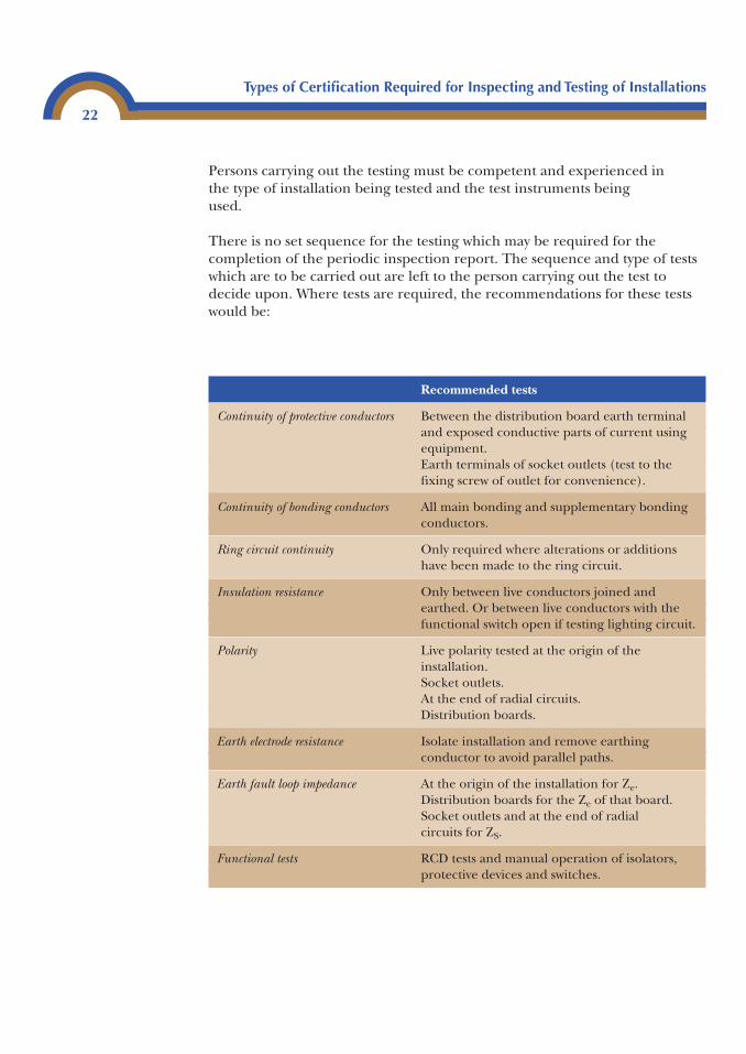
Persons carrying out the testing must be competent and experienced in the type of installation being tested and the test instruments being used.
There is no set sequence for the testing which may be required for thecompletion of the periodic inspection report. The sequence and type of testswhich are to be carried out are left to the person carrying out the test todecide upon. Where tests are required, the recommendations for these testswould be:
Types of Certification Required for Inspecting and Testing of Installations
22
Recommended tests
Continuity of protective conductors Between the distribution board earth terminaland exposed conductive parts of current usingequipment.Earth terminals of socket outlets (test to thefixing screw of outlet for convenience).
Continuity of bonding conductors All main bonding and supplementary bondingconductors.
Ring circuit continuity Only required where alterations or additions have been made to the ring circuit.
Insulation resistance Only between live conductors joined andearthed. Or between live conductors with thefunctional switch open if testing lighting circuit.
Polarity Live polarity tested at the origin of theinstallation.Socket outlets.At the end of radial circuits.Distribution boards.
Earth electrode resistance Isolate installation and remove earthingconductor to avoid parallel paths.
Earth fault loop impedance At the origin of the installation for Ze.Distribution boards for the Ze of that board.Socket outlets and at the end of radialcircuits for ZS.
Functional tests RCD tests and manual operation of isolators,protective devices and switches.
Voltage drop in conductors
It is part of the inspection process to ensure that installed conductors havebeen correctly selected for current carrying capacity and voltage drop. To check the suitability of the current carrying capacity it is simply a matter oflooking at the installation method, and then checking on the current carryingcapacity tables for the cable in Appendix 4 of BS 7671.
To ensure that the cable meets the voltage drop requirements is slightly morecomplex. A simple method is to measure the voltage at the origin of thecircuit, and then measure the voltage at the end of the circuit with the loadconnected and switched on. The difference between the two measurementswill be the volt drop.
If the first method is impractical, then a resistance test should be carried outbetween the phase and neutral of the circuit. This test is carried out using thesame method as the R1 � R2 test although, instead of the test being betweenphase and CPC, it is between the phase and neutral for the circuit. Once theresistance R1 + Rn of the circuit has been measured it should be multiplied by the current that will flow in the circuit. This will give you the volt drop forthe circuit.
Example
A circuit is wired in 2.5 mm2 and is 25 metres in length. The current in thecircuit is 18 amps.
The measured value of resistance is 0.37 Ω
Voltage drop � I � R � V
18 � 0.37 � 6.66 volts.
This is the voltage drop for the circuit.
Types of Certification Required for Inspecting and Testing of Installations
23

This page intentionally left blank
Testing of electricalinstallations 3
Safe isolation
It cannot be over-emphasized how important it is that isolation of electricalcircuits is carried out in a set sequence, and that this sequence is repeatedeach time a circuit or complete installation is to be isolated.
If the same procedure is followed each time isolation is carried out, it willsoon become a habit, which can only be a good thing as it may save your life.
It is vital that the correct test equipment is used for isolation and that it complieswith the Health and Safety Executive document GS 38. This document givesguidance on the use of test equipment, particularly leads and probes.
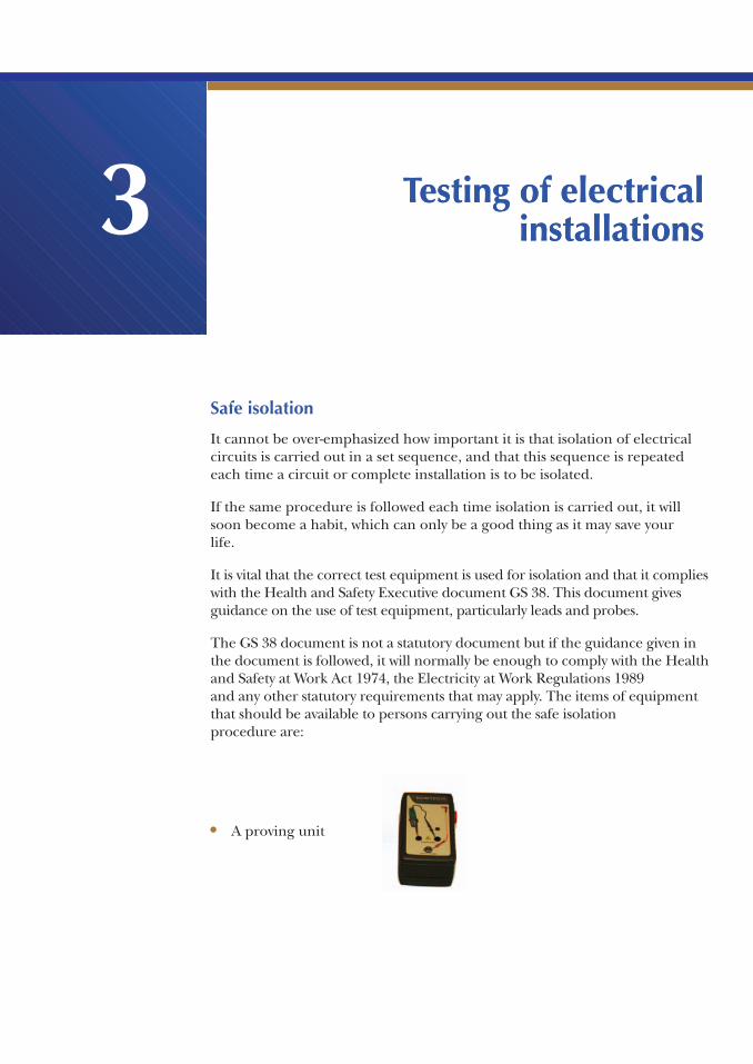
The GS 38 document is not a statutory document but if the guidance given inthe document is followed, it will normally be enough to comply with the Healthand Safety at Work Act 1974, the Electricity at Work Regulations 1989 and any other statutory requirements that may apply. The items of equipmentthat should be available to persons carrying out the safe isolation procedure are:
Testing of electricalinstallations 3
• A proving unit
Testing of Electrical Installations
26
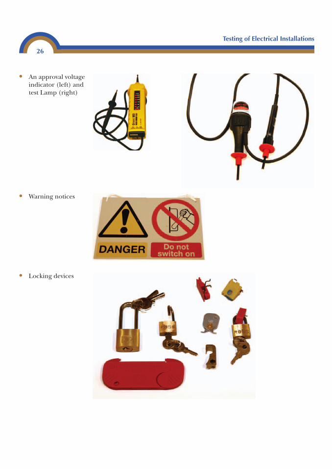
• An approval voltageindicator (left) andtest Lamp (right)
• Warning notices
• Locking devices
Testing of Electrical Installations
27
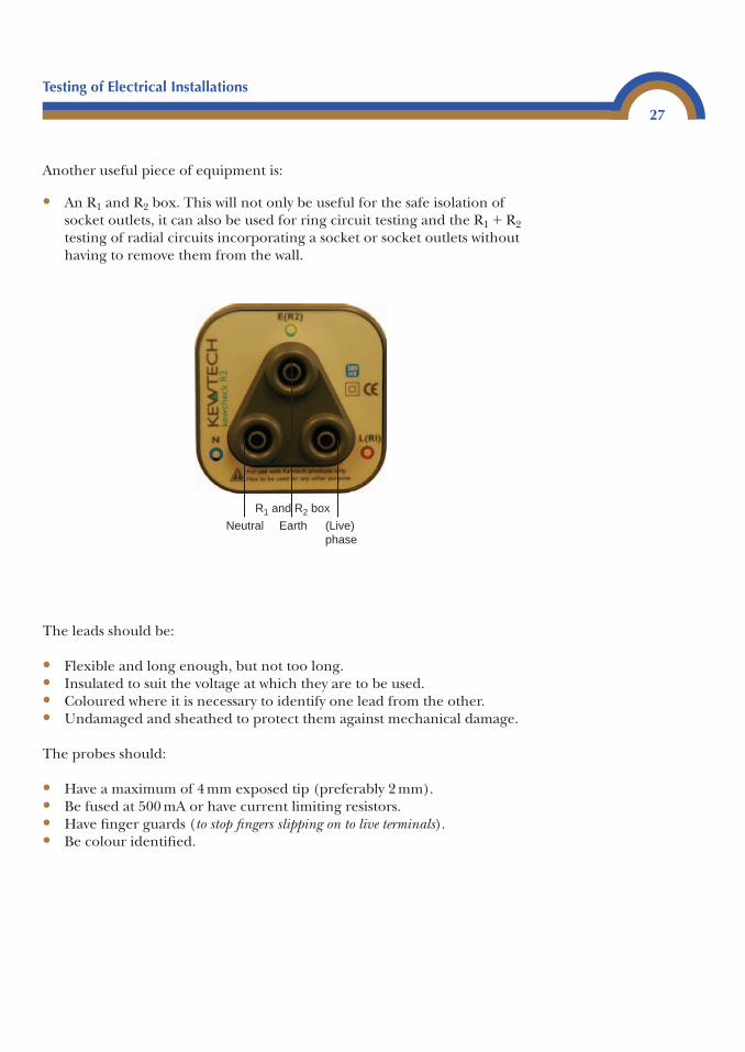
Earth (Live)phase
Neutral
R1 and R2 box
Another useful piece of equipment is:
• An R1 and R2 box. This will not only be useful for the safe isolation ofsocket outlets, it can also be used for ring circuit testing and the R1 � R2testing of radial circuits incorporating a socket or socket outlets withouthaving to remove them from the wall.
The leads should be:
• Flexible and long enough, but not too long.• Insulated to suit the voltage at which they are to be used.• Coloured where it is necessary to identify one lead from the other.• Undamaged and sheathed to protect them against mechanical damage.
The probes should:
• Have a maximum of 4 mm exposed tip (preferably 2 mm).• Be fused at 500 mA or have current limiting resistors.• Have finger guards (to stop fingers slipping on to live terminals).• Be colour identified.
Isolation procedure
It is very important to ensure that the circuit that you want to isolate is livebefore you start. To check this, a voltage indicator/test lamp or a piece ofequipment that is already connected to the circuit should be used. If itappears that the circuit is already dead, you need to know why.
• Is somebody else working on it?• Is the circuit faulty?• Is it connected?• Has there been a power cut?
You must make absolutely certain that you and you alone are in control of the circuit to be worked on. Providing the circuit is live you can proceed asfollows:
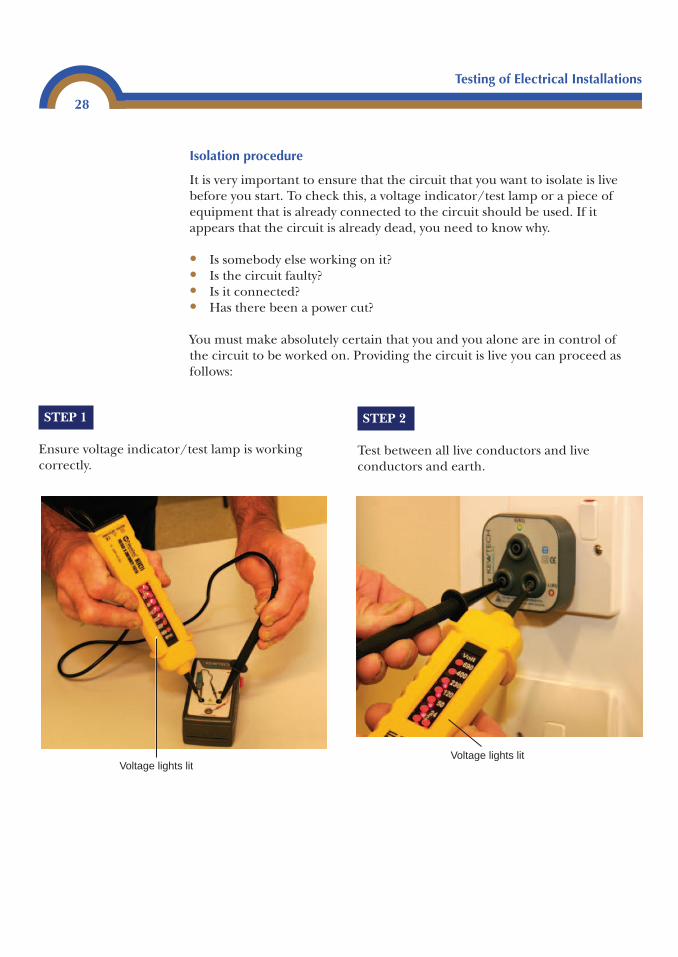
STEP 1
Ensure voltage indicator/test lamp is workingcorrectly.
STEP 2
Test between all live conductors and liveconductors and earth.
Testing of Electrical Installations
28
Voltage lights litVoltage lights lit
Testing of Electrical Installations
29
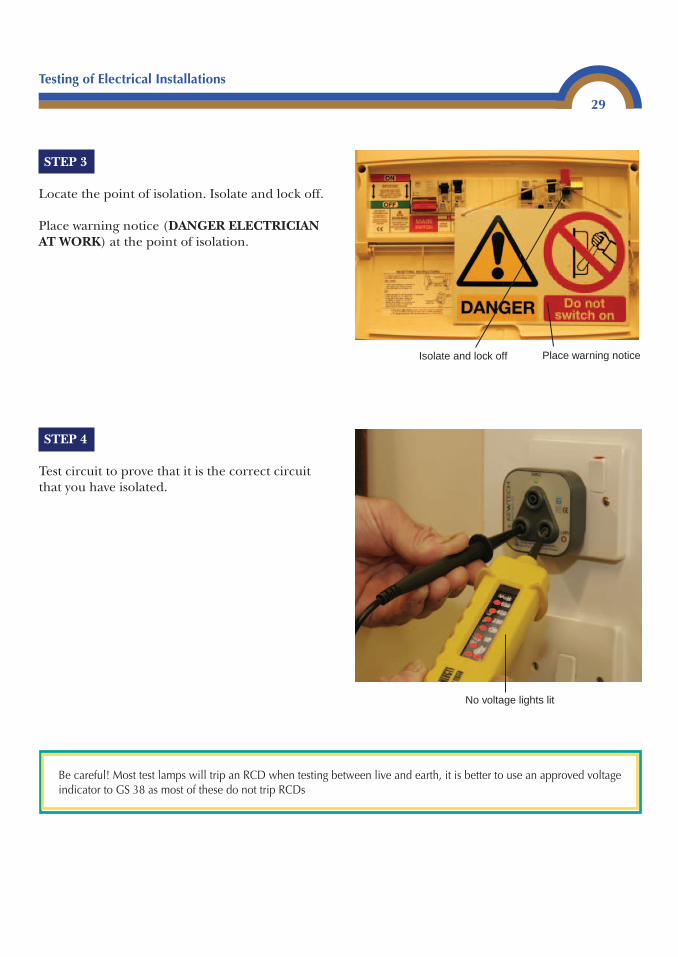
STEP 3
Locate the point of isolation. Isolate and lock off.
Place warning notice (DANGER ELECTRICIANAT WORK) at the point of isolation.
STEP 4
Test circuit to prove that it is the correct circuitthat you have isolated.
Be careful! Most test lamps will trip an RCD when testing between live and earth, it is better to use an approved voltageindicator to GS 38 as most of these do not trip RCDs
Isolate and lock off Place warning notice
No voltage lights lit
It is now safe to begin work.
If the circuit which has been isolated is going to be disconnected at theconsumer’s unit or distribution board, REMEMBER the distribution boardshould also be isolated. The Electricity at Work Regulations 1989 do notpermit live working.
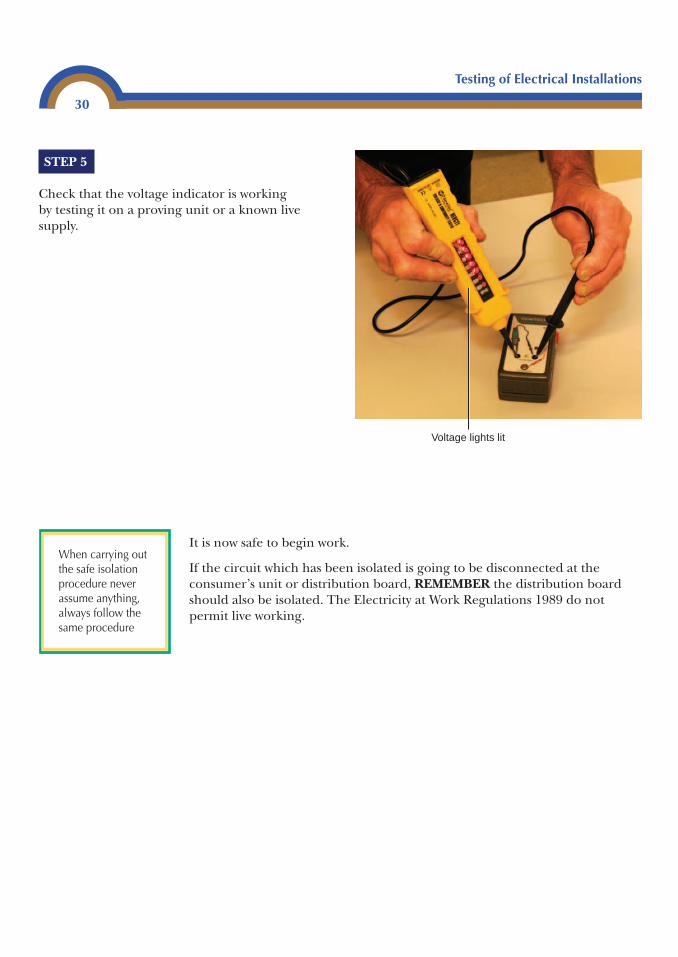
STEP 5
Check that the voltage indicator is workingby testing it on a proving unit or a known livesupply.
Testing of Electrical Installations
30
Voltage lights lit
When carrying outthe safe isolationprocedure neverassume anything,always follow thesame procedure
Testing for continuity of protective conductors
Main equipotential bonding
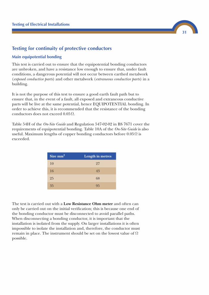
This test is carried out to ensure that the equipotential bonding conductorsare unbroken, and have a resistance low enough to ensure that, under faultconditions, a dangerous potential will not occur between earthed metalwork(exposed conductive parts) and other metalwork (extraneous conductive parts) in abuilding.
It is not the purpose of this test to ensure a good earth fault path but toensure that, in the event of a fault, all exposed and extraneous conductiveparts will be live at the same potential, hence EQUIPOTENTIAL bonding. Inorder to achieve this, it is recommended that the resistance of the bondingconductors does not exceed 0.05Ω.
Table 54H of the On-Site Guide and Regulation 547-02-02 in BS 7671 cover therequirements of equipotential bonding. Table 10A of the On-Site Guide is alsouseful. Maximum lengths of copper bonding conductors before 0.05Ω isexceeded.
The test is carried out with a Low Resistance Ohm meter and often can only be carried out on the initial verification; this is because one end of the bonding conductor must be disconnected to avoid parallel paths. When disconnecting a bonding conductor, it is important that the installation is isolated from the supply. On larger installations it is oftenimpossible to isolate the installation and, therefore, the conductor mustremain in place. The instrument should be set on the lowest value of Ωpossible.
Testing of Electrical Installations
31
Size mm2 Length in metres
10 27
16 43
25 68
35 95
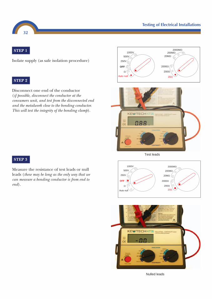
STEP 1
Isolate supply (as safe isolation procedure)
STEP 2
Disconnect one end of the conductor (if possible, disconnect the conductor at theconsumers unit, and test from the disconnected endand the metalwork close to the bonding conductor.This will test the integrity of the bonding clamp).
STEP 3
Measure the resistance of test leads or nullleads (these may be long as the only way that wecan measure a bonding conductor is from end toend).
Testing of Electrical Installations
32
1000V2000M�
2000�
200M�
200�
20M�
20�
500V
250V
OFF
�
Auto null
Test leads
Nulled leads
1000V
500V
250V
OFF
�
2000M�
2000�
200M�
200�
20M�
20�Auto null
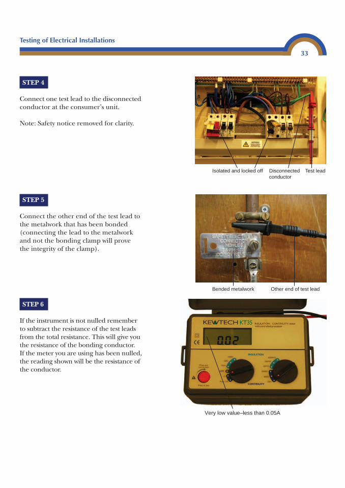
STEP 4
Connect one test lead to the disconnectedconductor at the consumer’s unit.
Note: Safety notice removed for clarity.
STEP 5
Connect the other end of the test lead tothe metalwork that has been bonded(connecting the lead to the metalworkand not the bonding clamp will provethe integrity of the clamp).
STEP 6
If the instrument is not nulled rememberto subtract the resistance of the test leadsfrom the total resistance. This will give youthe resistance of the bonding conductor. If the meter you are using has been nulled,the reading shown will be the resistance ofthe conductor.
Testing of Electrical Installations
33
Disconnected conductor
Isolated and locked off Test lead
Bended metalwork Other end of test lead
Very low value–less than 0.05A
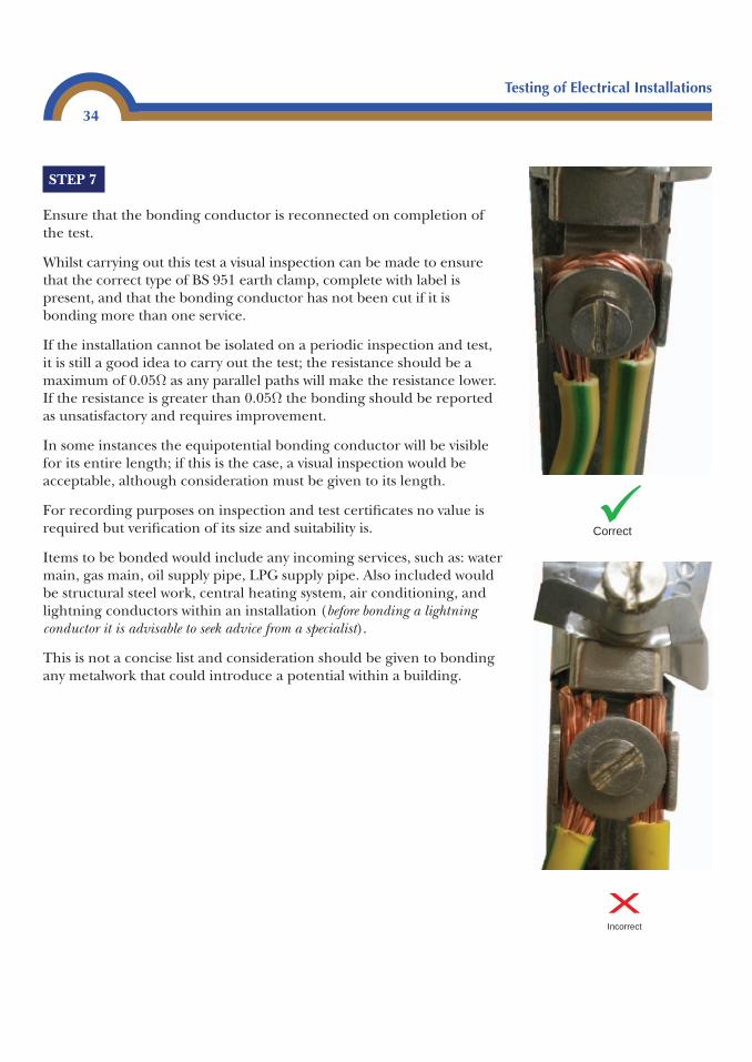
STEP 7
Ensure that the bonding conductor is reconnected on completion ofthe test.
Whilst carrying out this test a visual inspection can be made to ensurethat the correct type of BS 951 earth clamp, complete with label ispresent, and that the bonding conductor has not been cut if it isbonding more than one service.
If the installation cannot be isolated on a periodic inspection and test,it is still a good idea to carry out the test; the resistance should be amaximum of 0.05Ω as any parallel paths will make the resistance lower.If the resistance is greater than 0.05Ω the bonding should be reportedas unsatisfactory and requires improvement.
In some instances the equipotential bonding conductor will be visiblefor its entire length; if this is the case, a visual inspection would beacceptable, although consideration must be given to its length.
For recording purposes on inspection and test certificates no value isrequired but verification of its size and suitability is.
Items to be bonded would include any incoming services, such as: watermain, gas main, oil supply pipe, LPG supply pipe. Also included wouldbe structural steel work, central heating system, air conditioning, andlightning conductors within an installation (before bonding a lightningconductor it is advisable to seek advice from a specialist).
This is not a concise list and consideration should be given to bondingany metalwork that could introduce a potential within a building.
Testing of Electrical Installations
34
Correct
Incorrect
Continuity of supplementary bondingThere are two general reasons for carrying out supplementary equipotentialbonding.
Supplementary bonding 1
This is required when there is an increased risk of electric shock (Regulation471-08-01).
BS 7671 states that supplementary bonding must be installed inbathrooms/shower rooms and swimming pools.
It should be remembered that, although Regulation 601-04-01 requires thatwe must bond the exposed and extraneous conductive parts in bathrooms,this Regulation applies only to zones 1, 2, and 3.
Due consideration must be given to other areas where there is an increasedrisk of electric shock. There is no specific requirement to carry outsupplementary bonding in Kitchens. However, if it is thought by the installerthat there is an increased risk of electric shock, there is no reason whybonding could not be carried out, it will do no harm providing it is carriedout correctly.
On occasions it is often useful to carry out supplementary bonding,particularly under Kitchen sinks. This may not be for electrical reasons, more for visual purposes – bonding is not well understood by many people. A possible scenario might be where you may have travelled 20/30 miles to fit a Kitchen and completed everything to comply with the requiredregulations. A few days later, before you have been paid for the work youreceive a phone call from your customer, informing you that his next doorneighbour has spotted that you have not bonded the sink. Of course yourcustomer will believe his neighbour is right and that you have forgottensomething or tried to save a bit of money. The choice is now yours, do you tryand convince your customer that his neighbour is wrong or do you travel backto the job to carry out the bonding to ensure payment? Perhaps for the sakeof a couple of earth clamps and a short length of 4 mm2, it would have beencheaper just to bond it in the first place.
Where complimentary supplementary bonding is used in this instance a testmust be carried out to ensure that the resistance between exposed andextraneous conductive parts is in place and has a resistance of less than0.05 Ω. The instrument to be used is a low resistance ohm meter.
Testing of Electrical Installations
35
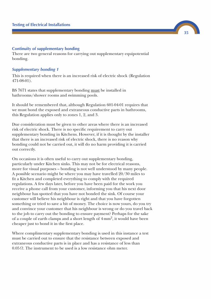
A visual check must be made to ensure that thecorrect earth clamps have been used and that theyhave the correct labels attached.
It is perfectly acceptable to use the pipe work andstructural steelwork within the area as a bondingconductor, and bonding can be carried out adjacentto the area providing that the integrity of the pipework/steelwork can be assured. An airing cupboardwould be a good example of a suitable place tobond.
If it is necessary for the lighting point or electricshower in a bathroom (remember if they are not withinzones 1, 2, or 3 no bonding is required), there is noreason why the bonding conductor could not besimply attached to a pipe within the roof space,which is bonded elsewhere and passes near theitem which requires bonding. The correct bondingclamps and labels should always be used.
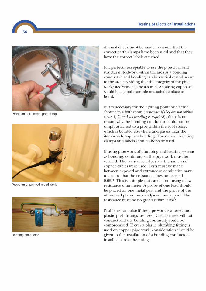
If using pipe work of plumbing and heating systemsas bonding, continuity of the pipe work must beverified. The resistance values are the same as ifcopper cables were used. Tests must be madebetween exposed and extraneous conductive partsto ensure that the resistance does not exceed0.05Ω. This is a simple test carried out using a lowresistance ohm meter. A probe of one lead shouldbe placed on one metal part and the probe of theother lead placed on an adjacent metal part. Theresistance must be no greater than 0.05Ω.
Problems can arise if the pipe work is altered andplastic push fittings are used. Clearly these will notconduct and the bonding continuity could becompromised. If ever a plastic plumbing fitting isused on copper pipe work, consideration should begiven to the installation of a bonding conductorinstalled across the fitting.
Testing of Electrical Installations
36
Probe on solid metal part of tap
Probe on unpainted metal work
Bonding conductor
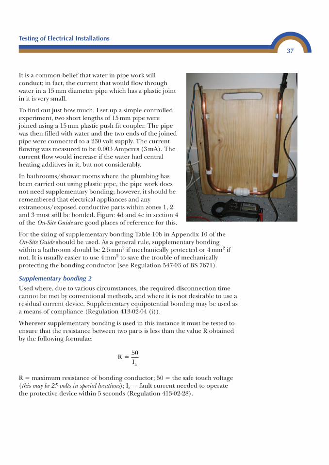
It is a common belief that water in pipe work willconduct; in fact, the current that would flow throughwater in a 15 mm diameter pipe which has a plastic jointin it is very small.
To find out just how much, I set up a simple controlledexperiment, two short lengths of 15 mm pipe werejoined using a 15 mm plastic push fit coupler. The pipewas then filled with water and the two ends of the joinedpipe were connected to a 230 volt supply. The currentflowing was measured to be 0.003 Amperes (3 mA). Thecurrent flow would increase if the water had centralheating additives in it, but not considerably.
In bathrooms/shower rooms where the plumbing hasbeen carried out using plastic pipe, the pipe work doesnot need supplementary bonding; however, it should beremembered that electrical appliances and anyextraneous/exposed conductive parts within zones 1, 2and 3 must still be bonded. Figure 4d and 4e in section 4of the On-Site Guide are good places of reference for this.
For the sizing of supplementary bonding Table 10b in Appendix 10 of the On-Site Guide should be used. As a general rule, supplementary bondingwithin a bathroom should be 2.5 mm2 if mechanically protected or 4 mm2 ifnot. It is usually easier to use 4 mm2 to save the trouble of mechanicallyprotecting the bonding conductor (see Regulation 547-03 of BS 7671).
Supplementary bonding 2
Used where, due to various circumstances, the required disconnection timecannot be met by conventional methods, and where it is not desirable to use aresidual current device. Supplementary equipotential bonding may be used asa means of compliance (Regulation 413-02-04 (i)).
Wherever supplementary bonding is used in this instance it must be tested toensure that the resistance between two parts is less than the value R obtainedby the following formulae:
R � maximum resistance of bonding conductor; 50 � the safe touch voltage(this may be 25 volts in special locations); Ia � fault current needed to operatethe protective device within 5 seconds (Regulation 413-02-28).
RIa
�50
Testing of Electrical Installations
37
If the circuit is protected by a Residual current device Ia may be substituted by IΔn.
The fault current can be found in Appendix 3 in BS 7671 or by using thecalculation:
UOC � open circuit voltage of supply transformer; ZS � maximum earth loopimpedance for the protective device.
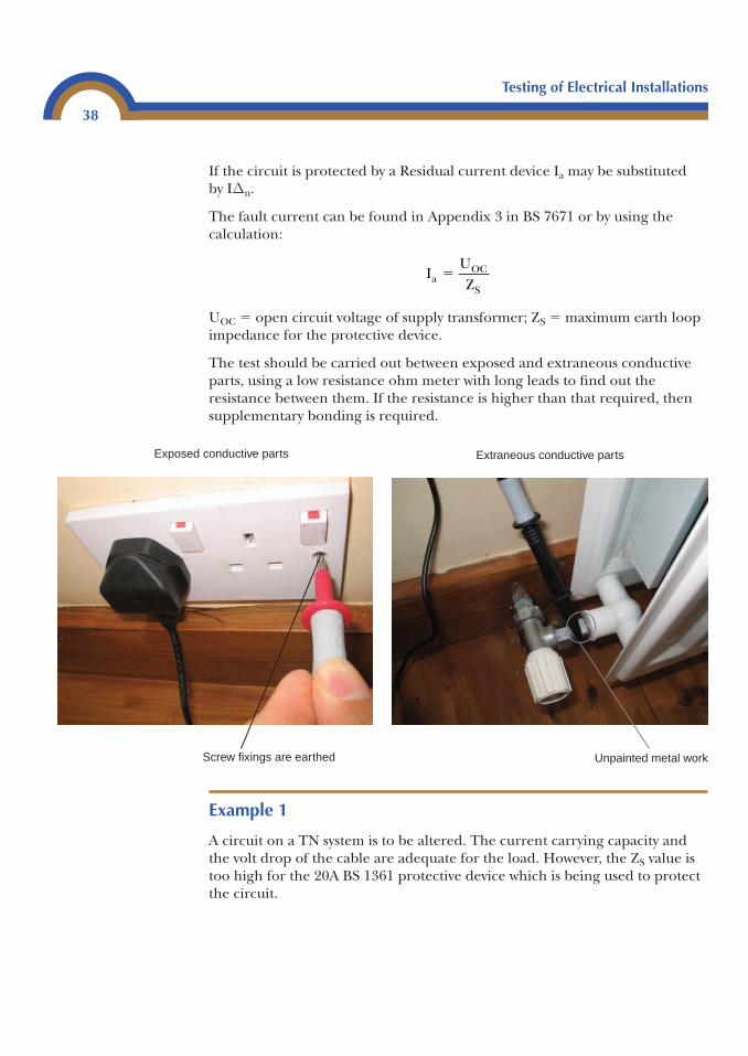
The test should be carried out between exposed and extraneous conductiveparts, using a low resistance ohm meter with long leads to find out theresistance between them. If the resistance is higher than that required, thensupplementary bonding is required.
IUZa
OC
S
�
Example 1
A circuit on a TN system is to be altered. The current carrying capacity andthe volt drop of the cable are adequate for the load. However, the ZS value istoo high for the 20A BS 1361 protective device which is being used to protectthe circuit.
Testing of Electrical Installations
38
Screw fixings are earthed
Exposed conductive parts
Unpainted metal work
Extraneous conductive parts
Testing of Electrical Installations
39
The maximum resistance permissible between exposed and extraneousconductive parts must be calculated.
The first step is to find the current that would cause automatic disconnection of the supply.
This value can also be found in Figure 3.1 of Appendix 3 of BS 7671 (it is rounded upto 82 amps).
The maximum permissible resistance between conductive parts can now be found by:
Supplementary bonding is installed where there is a risk of simultaneous contact with anyextraneous and exposed conductive parts. Its purpose is to ensure that the potential betweenany of these parts does not rise above a safe value. In most cases, this value is 50 volts,although some chapters in Part 6 of BS 7671 require a maximum potential of only 25 volts.
Determining if a part is extraneous, or just a piece of metalA test should be made using an insulation resistance tester set on mΩ,supplying 500 volts.
Connect one test lead to the metal part and the other lead to a known earth. Ifthe resistance value is 0.02 mΩ (20,000Ω) or greater, no supplementary bondingis required. If less than 0.02 mΩ, supplementary bonding should be carried out.
If we use Ohm’s law we can see how this works:
This shows that a current of 25 mA would flow between the conductive parts;this would of course only be 0.012 amp if the fault was on a single phase 230 volt supply. This current is unlikely to give a fatal electrical shock.
The test must not be confused with a continuity test. It is important that aninsulation resistance tester is used.
VR
I: A� �500
20 0000 025
,.
R50I
R5082
0.6
a
�
� � Ω
IUZ
I2402.93
81.91 amps
aOC
S
a
�
� �
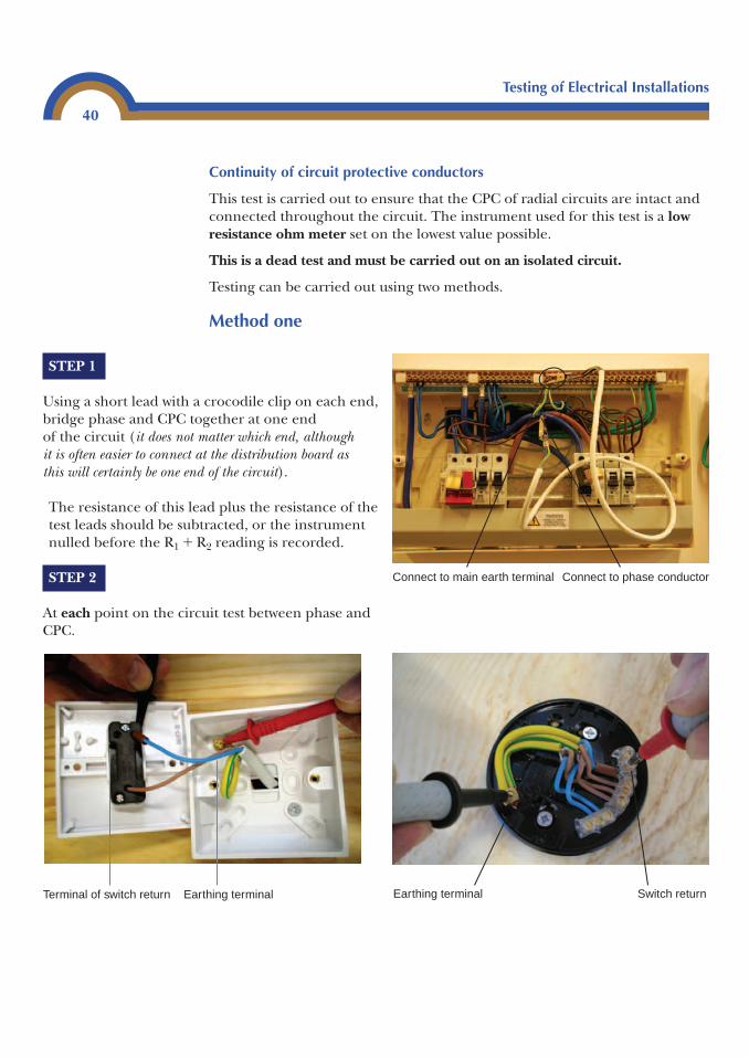
Testing of Electrical Installations
40
Earthing terminalTerminal of switch return Earthing terminal Switch return
Continuity of circuit protective conductors
This test is carried out to ensure that the CPC of radial circuits are intact andconnected throughout the circuit. The instrument used for this test is a lowresistance ohm meter set on the lowest value possible.
This is a dead test and must be carried out on an isolated circuit.
Testing can be carried out using two methods.
Method one
STEP 1
Using a short lead with a crocodile clip on each end,bridge phase and CPC together at one end of the circuit (it does not matter which end, although it is often easier to connect at the distribution board as this will certainly be one end of the circuit).
The resistance of this lead plus the resistance of thetest leads should be subtracted, or the instrumentnulled before the R1 � R2 reading is recorded.
STEP 2
At each point on the circuit test between phase andCPC.
Connect to phase conductorConnect to main earth terminal
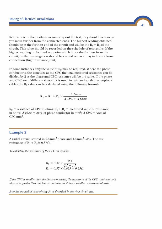
Keep a note of the readings as you carry out the test, they should increase asyou move further from the connected ends. The highest reading obtainedshould be at the furthest end of the circuit and will be the R1 � R2 of thecircuit. This value should be recorded on the schedule of test results. If thehighest reading is obtained at a point which is not the furthest from thecircuit, further investigation should be carried out as it may indicate a looseconnection (high resistance joint).
In some instances only the value of R2 may be required. Where the phaseconductor is the same size as the CPC the total measured resistance can bedivided by 2 as the phase and CPC resistance will be the same. If the phaseand CPC are of different sizes (this is usual in twin and earth thermoplasticcable) the R2 value can be calculated using the following formula:
R2 � resistance of CPC in ohms; R1 � R2 � measured value of resistance in ohms; A phase � Area of phase conductor in mm2; A CPC � Area of CPC mm2.
Example 2
A radial circuit is wired in 2.5 mm2 phase and 1.5 mm2 CPC. The testresistance of R1 � R2 is 0.37Ω.
To calculate the resistance of the CPC on its own:
If the CPC is smaller than the phase conductor, the resistance of the CPC conductor willalways be greater than the phase conductor as it has a smaller cross-sectional area.
Another method of determining R2 is described in the ring circuit test.
R 0.372.5
2.5 1.5R 0.37 0.625 0.23
2
2
� ��
� � � Ω
R R R2 1 2� � ��
A phaseA CPC A phase
Testing of Electrical Installations
41
Method two
This method will prove CPC continuity and is usually only used where thecircuit is wired in steel enclosures where parallel paths to the CPC may bepresent and the R1 � R2 value would not be a true value. Or where the CPCresistance is required for use with Table 41C of the Wiring Regulations.
This method uses a long lead. One end is connected to the earth terminal ofthe distribution board, and the other connected to a low resistance ohmmeter. The short lead of the ohm meter is then touched onto each fitting toensure that it is connected to the CPC. The highest reading minus theresistance of the leads can be recorded as the R2 reading.
If the furthest point of the circuit is known, and no parallel paths exist, theR1 � R2 reading can be carried out first using Method one, and then a testbetween earthed metal at each point can be made to ensure that the CPC isconnected to each point on the circuit, using Method two. This method isparticularly useful where there are a lot of enclosed metal fittings anddismantling them would be impractical.
Ring final circuit test
The purpose of this test is to ensure that:
• The cables form a complete ring.• There are no interconnections.• The polarity is correct on all socket outlets.
When this test is carried out correctly it also gives you the R1 and R2 value ofthe ring and identifies spurs.
Table 8A in the On-Site Guide provides information on final circuits for socketoutlets. This table states that a ring circuit is to be wired in 2.5 mm2 phaseconductor and 1.5 mm2 CPC as a minimum size. This type of circuit is an A1ring and should be protected by a 30/32 amp overcurrent protective device.
Complete ring circuit
A test must be carried out on the conductors to verify that they form acomplete loop. If it is found that they do not, overloading of the cables couldoccur. In installations where more than one ring circuit has been installed, itis possible for the ends of the ring to become muddled, resulting in thecircuits being supplied through two protective devices.
Testing of Electrical Installations
42
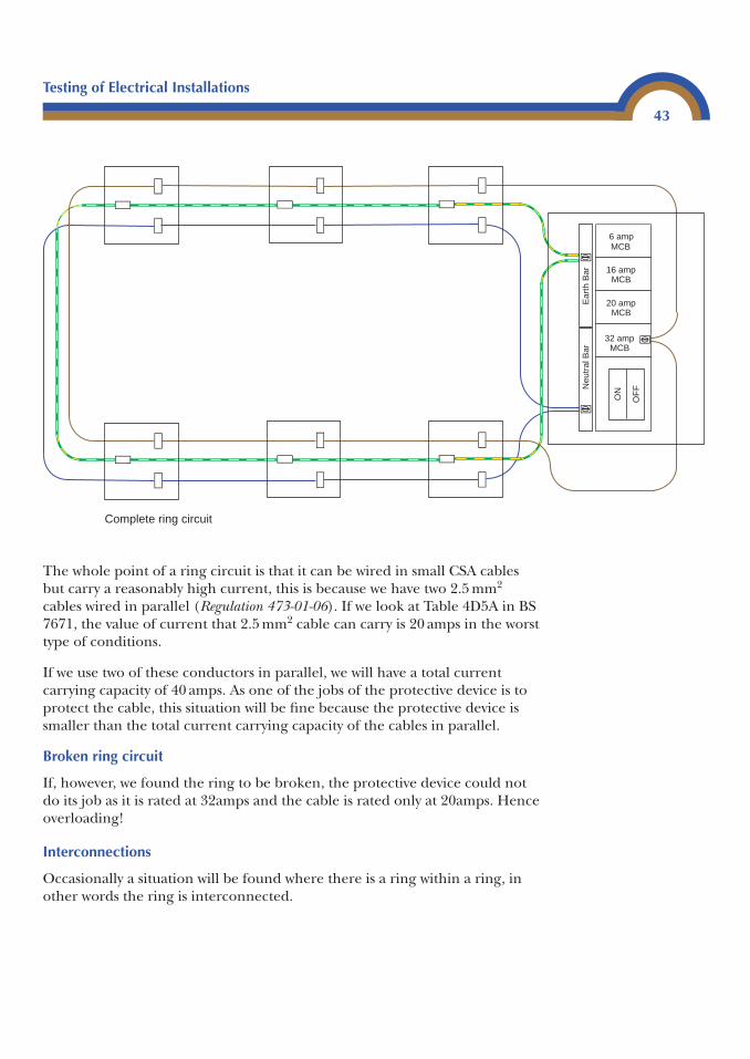
Testing of Electrical Installations
43
The whole point of a ring circuit is that it can be wired in small CSA cablesbut carry a reasonably high current, this is because we have two 2.5 mm2
cables wired in parallel (Regulation 473-01-06). If we look at Table 4D5A in BS7671, the value of current that 2.5 mm2 cable can carry is 20 amps in the worsttype of conditions.
If we use two of these conductors in parallel, we will have a total currentcarrying capacity of 40 amps. As one of the jobs of the protective device is toprotect the cable, this situation will be fine because the protective device issmaller than the total current carrying capacity of the cables in parallel.
Broken ring circuit
If, however, we found the ring to be broken, the protective device could notdo its job as it is rated at 32amps and the cable is rated only at 20amps. Henceoverloading!
Interconnections
Occasionally a situation will be found where there is a ring within a ring, inother words the ring is interconnected.
32 amp MCB
20 amp MCB
16 amp MCB
6 amp MCB
Neu
tral
Bar
Ear
th B
ar
ON
OF
F
Complete ring circuit
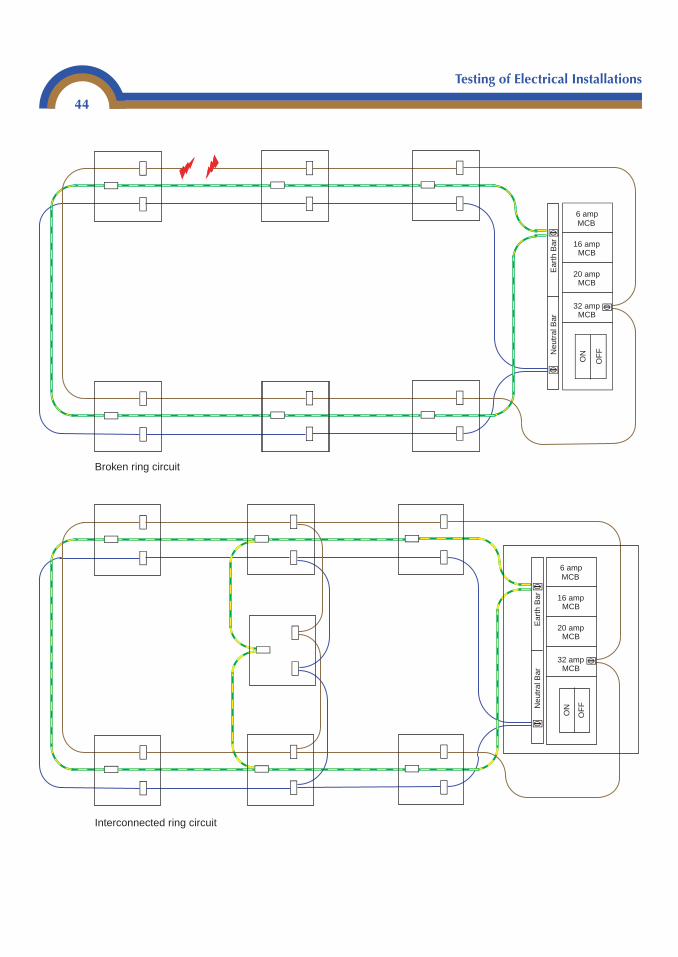
Testing of Electrical Installations
44
32 amp MCB
20 amp MCB
16 amp MCB
6 amp MCB
Neu
tral
Bar
Ear
th B
ar
ON
OF
F
Broken ring circuit
32 ampMCB
20 ampMCB
16 ampMCB
6 amp MCB
Neu
tral
Bar
Ear
th B
ar
ON
OF
F
Interconnected ring circuit
Testing of Electrical Installations
45
This situation, as it is, will not present a danger. However, it will make it verydifficult for a ring final circuit test to be carried out as, even if the correctends of the ring are connected together, different values will be found atvarious points of the ring. If one loop is broken, a test at the consumer’s unitwill still show a complete ring. It will not be until further tests are performedthat the interconnection/broken loop will be found.
Polarity
Each socket outlet must be checked to ensure that the conductors areconnected into the correct terminals. Clearly if they are not, serious dangercould occur when appliances are plugged in.
It could be that phase and neutral are the wrong polarity; the result of this isthat the neutral would be switched in any piece of equipment with a singlepole operating switch.
If the live conductors and CPC are connected with reverse polarity, then the caseof any Class 1 equipment could become live and result in a fatal electric shock.
Performing the test
The instrument required is a low resistance ohm meter set on the lowest scale,typically 20Ω. Be sure to zero the instrument or subtract the resistance of theleads each time you take a reading.
This is a dead test! Safe isolation must be carried out before working on this circuit
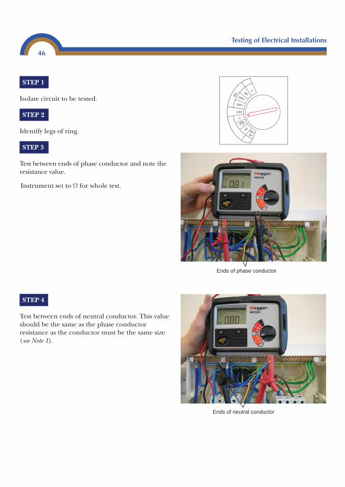
Testing of Electrical Installations
46
STEP 4
Test between ends of neutral conductor. This valueshould be the same as the phase conductorresistance as the conductor must be the same size(see Note 1).
Ends of phase conductor
V1kV
500V
250V
OFF
SET UP
kΩ
MΩ
Ω
Instrument set to Ω for whole test.
Ends of neutral conductor
STEP 1
Isolate circuit to be tested.
STEP 2
Identify legs of ring.
STEP 3
Test between ends of phase conductor and note theresistance value.
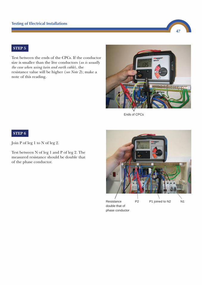
Testing of Electrical Installations
47
STEP 5
Test between the ends of the CPCs. If the conductorsize is smaller than the live conductors (as is usuallythe case when using twin and earth cable), theresistance value will be higher (see Note 2); make anote of this reading.
STEP 6
Join P of leg 1 to N of leg 2.
Test between N of leg 1 and P of leg 2. Themeasured resistance should be double thatof the phase conductor.
Ends of CPCs
Resistance double that of phase conductor
P2 P1 joined to N2 N1
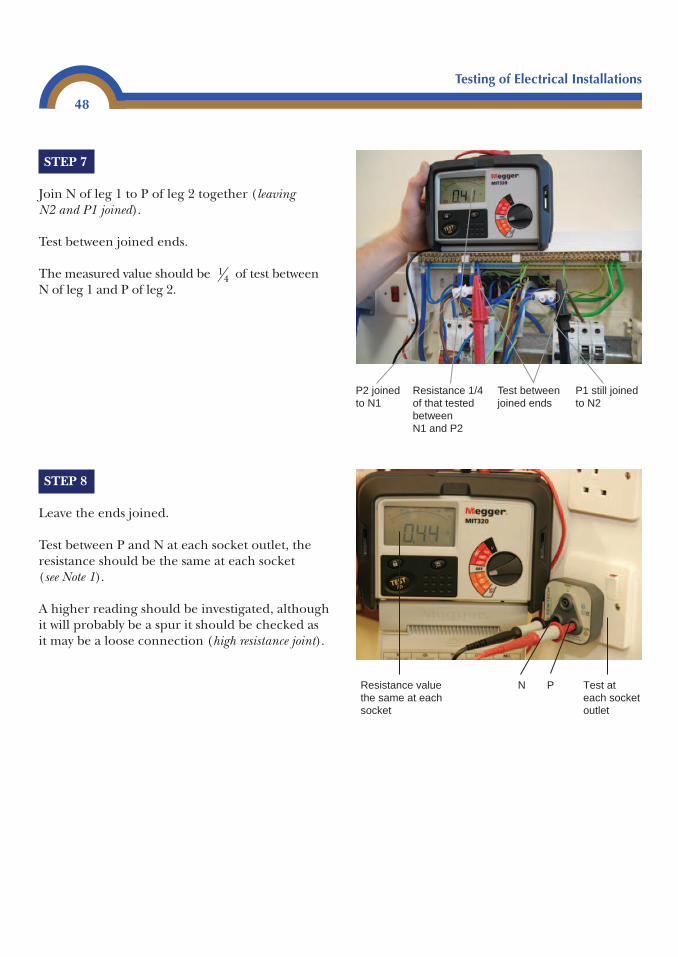
Testing of Electrical Installations
48
STEP 7
Join N of leg 1 to P of leg 2 together (leaving N2 and P1 joined).
Test between joined ends.
The measured value should be of test betweenN of leg 1 and P of leg 2.
14
STEP 8
Leave the ends joined.
Test between P and N at each socket outlet, theresistance should be the same at each socket (see Note 1).
A higher reading should be investigated, althoughit will probably be a spur it should be checked asit may be a loose connection (high resistance joint).
Resistance value the same at each socket
N P Test at each socket outlet
Test betweenjoined ends
P2 joined to N1
P1 still joined to N2
Resistance 1/4 of that tested between N1 and P2
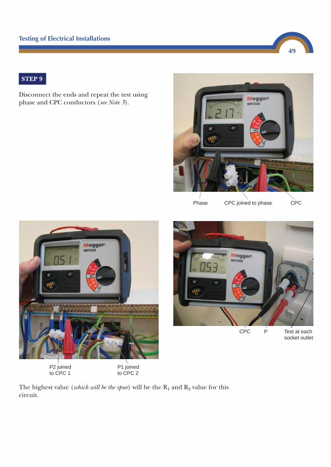
Testing of Electrical Installations
49
STEP 9
Disconnect the ends and repeat the test usingphase and CPC conductors (see Note 3).
Phase CPC joined to phase CPC
P2 joined to CPC 1
P1 joined to CPC 2
CPC P Test at each socket outlet
The highest value (which will be the spur) will be the R1 and R2 value for thiscircuit.
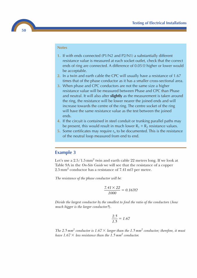
Testing of Electrical Installations
50
Example 3
Let’s use a 2.5/1.5 mm2 twin and earth cable 22 metres long. If we look atTable 9A in the On-Site Guide we will see that the resistance of a copper2.5 mm2 conductor has a resistance of 7.41 mΩ per metre.
The resistance of the phase conductor will be:
Divide the largest conductor by the smallest to find the ratio of the conductors (howmuch bigger is the larger conductor?).
The 2.5 mm2 conductor is 1.67 � larger than the 1.5 mm2 conductor; therefore, it musthave 1.67 � less resistance than the 1.5 mm2 conductor.
2.51.5
1.67�
7.41 221000
0.163�
� Ω
Notes
1. If with ends connected (P1/N2 and P2/N1) a substantially differentresistance value is measured at each socket outlet, check that the correctends of ring are connected. A difference of 0.05 Ω higher or lower wouldbe acceptable.
2. In a twin and earth cable the CPC will usually have a resistance of 1.67times that of the phase conductor as it has a smaller cross-sectional area.
3. When phase and CPC conductors are not the same size a higherresistance value will be measured between Phase and CPC than Phaseand neutral. It will also alter slightly as the measurement is taken aroundthe ring, the resistance will be lower nearer the joined ends and willincrease towards the centre of the ring. The centre socket of the ring will have the same resistance value as the test between the joined ends.
4. If the circuit is contained in steel conduit or trunking parallel paths maybe present, this would result in much lower R1 � R2 resistance values.
5. Some certificates may require rn to be documented. This is the resistanceof the neutral loop measured from end to end.
Testing of Electrical Installations
51
If we now multiply the resistance of the phase conductor by 1.67:0.163 � 1.67 � 0.27 Ω this is the resistance of the 1.5 mm2 conductor.
We can check this by looking at Table 9A of the On-Site Guide once again, and we cansee that the resistance of 1.5 mm2 copper is 12.10 mΩ per metre. Therefore, 22 metres of1.5 mm2 copper will be:
As a final check, if we look at Table 9A of the On-Site Guide for the resistance of a2.5 mm2/1.5 mm2 cable, we will see that it has a resistance of 19.51 mΩ per metre, andthat 22 metres of it will have a resistance of:
The resistance value of the 2.5 mm2 is 0.163Ω; and the resistance value of the 1.5 mm2 is 0.266Ω.
If we add them together: 0.163Ω � 0.266Ω � 0.429Ω. Finally, 0.429Ω is theresistance of our 2.5 mm2/1.5 mm2 measured as one cable.
Insulation resistance test
This is a test that can be carried out on a complete installation or a singlecircuit, whichever is suitable or required. The test is necessary to find out ifthere is likely to be any leakage of current through the insulated parts of theinstallation. A leakage could occur for various reasons.
A good way to think of this test is to relate it to a pressure test – we know thatvoltage is the pressure where the current is located in a cable. On a lowvoltage circuit, the expected voltage would be around 230 V a.c. The voltageused in an insulation test on a 230 V circuit is 500 V, which is more thandouble the normal circuit voltage. Therefore, it can be seen as a pressure test similar to a plumber pressure testing the central heating pipes.
Low insulation resistance
Cable insulation could deteriorate through age. A low insulation resistance caused through age will often be found in installations whererubber-insulated cables have been used. Cables which are crushed under floorboards, clipped on edge, or worn thin where pulled through holes in joistsnext to other cables, can give a very low reading.
22 19.511000
0.429�
� Ω
22 12.101000
0.266�
� Ω
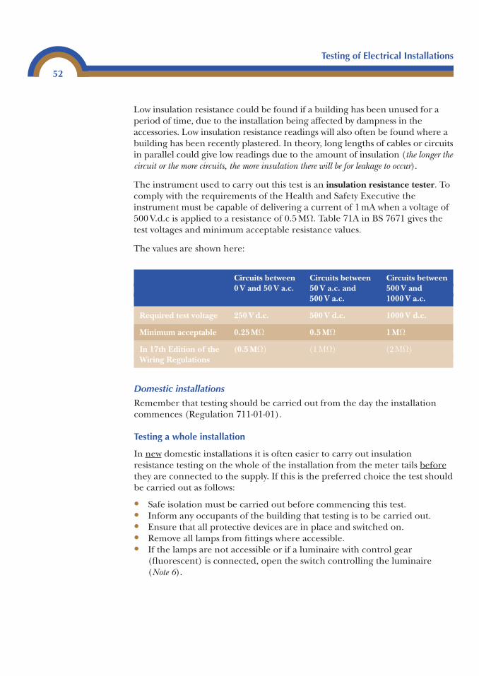
Testing of Electrical Installations
52
Low insulation resistance could be found if a building has been unused for aperiod of time, due to the installation being affected by dampness in theaccessories. Low insulation resistance readings will also often be found where abuilding has been recently plastered. In theory, long lengths of cables or circuitsin parallel could give low readings due to the amount of insulation (the longer thecircuit or the more circuits, the more insulation there will be for leakage to occur).
The instrument used to carry out this test is an insulation resistance tester. Tocomply with the requirements of the Health and Safety Executive theinstrument must be capable of delivering a current of 1 mA when a voltage of500 V.d.c is applied to a resistance of 0.5 MΩ. Table 71A in BS 7671 gives thetest voltages and minimum acceptable resistance values.
The values are shown here:
Domestic installations
Remember that testing should be carried out from the day the installationcommences (Regulation 711-01-01).
Testing a whole installation
In new domestic installations it is often easier to carry out insulationresistance testing on the whole of the installation from the meter tails beforethey are connected to the supply. If this is the preferred choice the test shouldbe carried out as follows:
• Safe isolation must be carried out before commencing this test.• Inform any occupants of the building that testing is to be carried out.• Ensure that all protective devices are in place and switched on.• Remove all lamps from fittings where accessible.• If the lamps are not accessible or if a luminaire with control gear
(fluorescent) is connected, open the switch controlling the luminaire(Note 6).
Circuits between Circuits between Circuits between 0 V and 50 V a.c. 50 V a.c. and 500 V and
500 V a.c. 1000 V a.c.
Required test voltage 250 V d.c. 500 V d.c. 1000 V d.c.
Minimum acceptable 0.25 MΩ 0.5 MΩ 1 MΩ
In 17th Edition of the (0.5 MΩ) (1 ΜΩ) (2 ΜΩ)Wiring Regulations
Testing of Electrical Installations
53
The same applies to extra low voltage transformers.
• Where dimmer switches are fitted it is important that they are eitherremoved and the switch wires joined, or that the switch is bypassed (Note 7).
• Any accessories with indicator lamps are switched off (Note 8).• Passive infra red detectors (PIRs) are removed or bypassed (Note 9).• All fixed equipment such as cookers, immersion heaters, boilers and
television amplifiers are isolated.• Shaver sockets are disconnected or isolated (Note 9).• Items of portable equipment are unplugged.
Great care must be taken as, during this test, 500 V will be passed through anyelectrical equipment which is left connected. This could damage theequipment or, at the very least, cause low readings to be obtained during thetest. Once all precautions have been taken proceed with the test as follows:
Notes
1. The control equipment within discharge lamps will cause very lowreadings. It is quite acceptable to isolate the fitting by turning off theswitch. This is more desirable than disconnecting the fitting. After the testbetween live conductors is completed the control switch for theluminaire should be closed before carrying out the test between liveconductors and CPC. This is to ensure that all live conductors are testedfor insulation resistance to earth.
2. Most dimmer switches have electronic components in them and thesecould be damaged if 500 V were to be applied to them. It is importantthat wherever possible the dimmer switches are removed and the phaseand switch return are joined together for the test.
3. Neon indicator lamps will be recognized as a load by the test instrumentand will give a very low insulation value. All that is required is for theswitch on the accessory to be turned off.
4. Passive infra red detectors will give very low readings and may be damagedby the test voltage. Either disconnect it or test between live conductors andearth only on circuits containing PIRs. The same applies to shaver sockets.
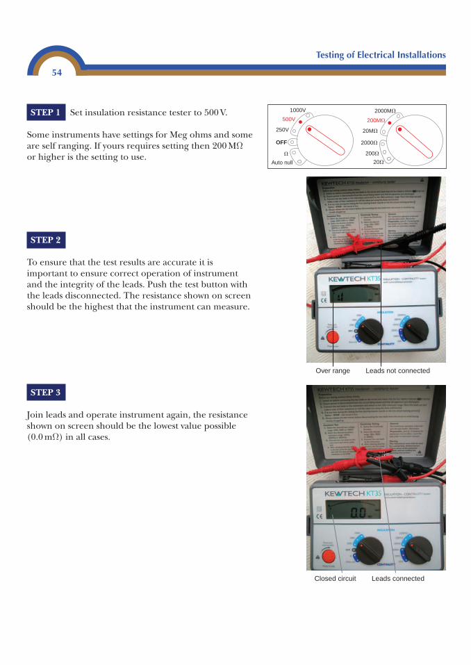
Testing of Electrical Installations
54
STEP 1 Set insulation resistance tester to 500 V.
Some instruments have settings for Meg ohms and someare self ranging. If yours requires setting then 200 MΩor higher is the setting to use.
STEP 2
To ensure that the test results are accurate it isimportant to ensure correct operation of instrumentand the integrity of the leads. Push the test button withthe leads disconnected. The resistance shown on screenshould be the highest that the instrument can measure.
STEP 3
Join leads and operate instrument again, the resistanceshown on screen should be the lowest value possible(0.0 mΩ) in all cases.
Leads not connectedOver range
1000V
500V
250V
Auto null
OFF
�
2000M�
2000�
200M�
200�
20M�
20�
Leads connectedClosed circuit
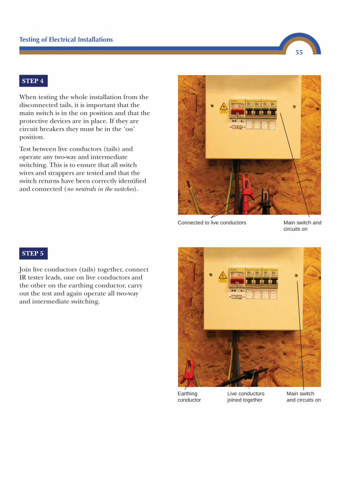
Testing of Electrical Installations
55
STEP 4
When testing the whole installation from thedisconnected tails, it is important that themain switch is in the on position and that theprotective devices are in place. If they arecircuit breakers they must be in the ‘on’position.
Test between live conductors (tails) andoperate any two-way and intermediateswitching. This is to ensure that all switchwires and strappers are tested and that theswitch returns have been correctly identifiedand connected (no neutrals in the switches).
STEP 5
Join live conductors (tails) together, connectIR tester leads, one on live conductors andthe other on the earthing conductor, carryout the test and again operate all two-wayand intermediate switching.
Main switch and circuits on
Live conductors joined together
Earthing conductor
Main switch and circuits on
Connected to live conductors
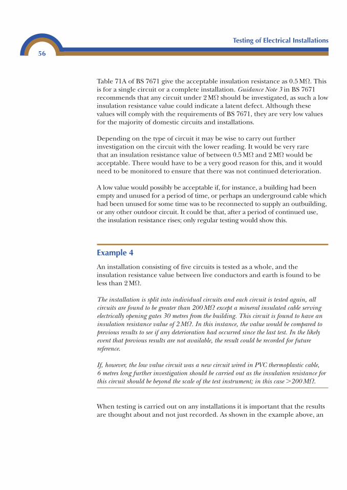
Testing of Electrical Installations
56
Table 71A of BS 7671 give the acceptable insulation resistance as 0.5 MΩ. Thisis for a single circuit or a complete installation. Guidance Note 3 in BS 7671recommends that any circuit under 2 MΩ should be investigated, as such a lowinsulation resistance value could indicate a latent defect. Although thesevalues will comply with the requirements of BS 7671, they are very low valuesfor the majority of domestic circuits and installations.
Depending on the type of circuit it may be wise to carry out furtherinvestigation on the circuit with the lower reading. It would be very rare that an insulation resistance value of between 0.5 MΩ and 2 MΩ would beacceptable. There would have to be a very good reason for this, and it wouldneed to be monitored to ensure that there was not continued deterioration.
A low value would possibly be acceptable if, for instance, a building had beenempty and unused for a period of time, or perhaps an underground cable whichhad been unused for some time was to be reconnected to supply an outbuilding,or any other outdoor circuit. It could be that, after a period of continued use,the insulation resistance rises; only regular testing would show this.
Example 4
An installation consisting of five circuits is tested as a whole, and theinsulation resistance value between live conductors and earth is found to beless than 2 MΩ.
The installation is split into individual circuits and each circuit is tested again, allcircuits are found to be greater than 200 MΩ except a mineral insulated cable servingelectrically opening gates 30 metres from the building. This circuit is found to have aninsulation resistance value of 2 MΩ. In this instance, the value would be compared toprevious results to see if any deterioration had occurred since the last test. In the likelyevent that previous results are not available, the result could be recorded for futurereference.
If, however, the low value circuit was a new circuit wired in PVC thermoplastic cable, 6 metres long further investigation should be carried out as the insulation resistance forthis circuit should be beyond the scale of the test instrument; in this case �200 MΩ.
When testing is carried out on any installations it is important that the resultsare thought about and not just recorded. As shown in the example above, an
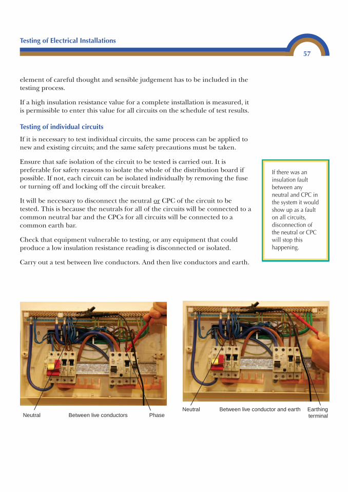
Testing of Electrical Installations
57
element of careful thought and sensible judgement has to be included in thetesting process.
If a high insulation resistance value for a complete installation is measured, itis permissible to enter this value for all circuits on the schedule of test results.
Testing of individual circuits
If it is necessary to test individual circuits, the same process can be applied tonew and existing circuits; and the same safety precautions must be taken.
Ensure that safe isolation of the circuit to be tested is carried out. It ispreferable for safety reasons to isolate the whole of the distribution board ifpossible. If not, each circuit can be isolated individually by removing the fuseor turning off and locking off the circuit breaker.
It will be necessary to disconnect the neutral or CPC of the circuit to betested. This is because the neutrals for all of the circuits will be connected to acommon neutral bar and the CPCs for all circuits will be connected to acommon earth bar.
Check that equipment vulnerable to testing, or any equipment that couldproduce a low insulation resistance reading is disconnected or isolated.
Carry out a test between live conductors. And then live conductors and earth.
Neutral PhaseBetween live conductors
If there was aninsulation faultbetween anyneutral and CPC inthe system it wouldshow up as a faulton all circuits,disconnection ofthe neutral or CPCwill stop thishappening.
Neutral Earthing terminal
Between live conductor and earth
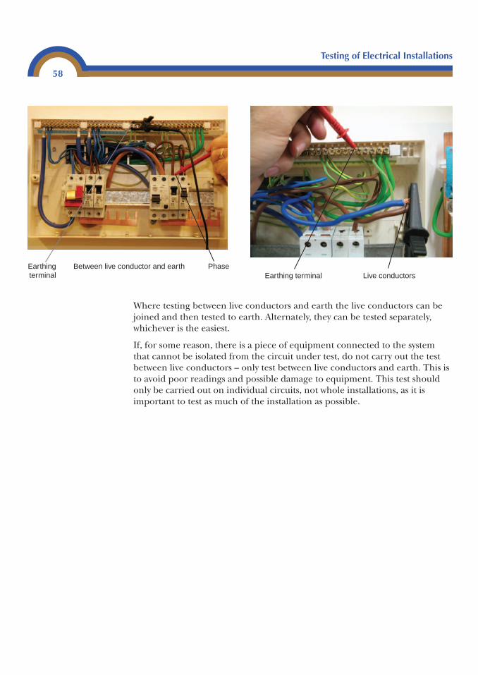
Testing of Electrical Installations
58
Where testing between live conductors and earth the live conductors can bejoined and then tested to earth. Alternately, they can be tested separately,whichever is the easiest.
If, for some reason, there is a piece of equipment connected to the systemthat cannot be isolated from the circuit under test, do not carry out the testbetween live conductors – only test between live conductors and earth. This isto avoid poor readings and possible damage to equipment. This test shouldonly be carried out on individual circuits, not whole installations, as it isimportant to test as much of the installation as possible.
Earthingterminal
PhaseBetween live conductor and earthEarthing terminal Live conductors
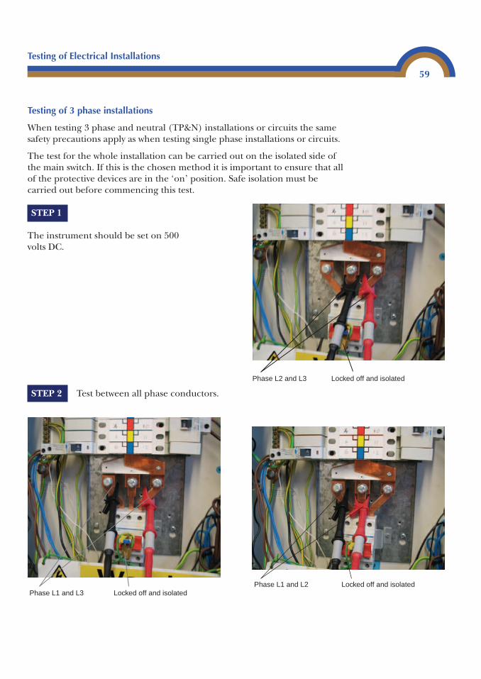
Testing of Electrical Installations
59
Testing of 3 phase installations
When testing 3 phase and neutral (TP&N) installations or circuits the samesafety precautions apply as when testing single phase installations or circuits.
The test for the whole installation can be carried out on the isolated side ofthe main switch. If this is the chosen method it is important to ensure that allof the protective devices are in the ‘on’ position. Safe isolation must becarried out before commencing this test.
STEP 1
The instrument should be set on 500volts DC.
STEP 2 Test between all phase conductors.
Phase L2 and L3 Locked off and isolated
Phase L1 and L3 Locked off and isolatedPhase L1 and L2 Locked off and isolated
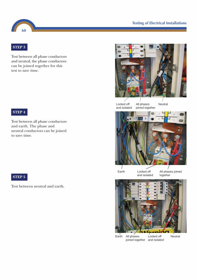
Testing of Electrical Installations
60
STEP 3
Test between all phase conductorsand neutral, the phase conductorscan be joined together for thistest to save time.
STEP 4
Test between all phase conductorsand earth. The phase andneutral conductors can be joinedto save time.
STEP 5
Test between neutral and earth.
Earth All phases joined together
Locked off and isolated
All phasesjoined together
Locked off and isolated
NeutralEarth
NeutralAll phases joined together
Locked off and isolated
Testing of Electrical Installations
61
STEP 6 The resistance values should be 2 MΩ or greater for each circuitand the whole installation must have an insulation resistance ofgreater than 0.5 MΩ.
STEP 7 If a circuit is found to have an insulation resistance of less than2 MΩ it should be investigated.
STEP 8 Ensure that any links used for testing are removed prior to theswitching on of the supply.
Be aware that if the live conductors are joined and then tested to earth,theoretically the insulation resistance value may be lower due to theconductors being in parallel.
Example 5
A three-phase sub-main is tested and the results are as follows:
L1 to earth is 130 MΩL2 to earth is 80 MΩL3 to earth is 50 MΩN to earth is 100 MΩ
If these conductors were now joined and tested to earth the value would be asgiven below.
Calculation is:
Put in the values:
Enter it this way into a calculator:
130X�1 � 80X�1 � 50X�1 � X�1 Answer is 19.92 MΩ
This value is still acceptable but lower because the conductors are in parallel.
When completing a Schedule of Test Results, it is important that youdocument exactly which insulation tests have been carried out. If it is notpossible to carry out a test between any conductors a note of this should bemade in the remarks column of the schedule.
1130
180
150
1100
10.05
19.92 M� � � � � Ω
1R1
1R2
1R3
1R4
1Rt
� � � �
Testing of Electrical Installations
62
Testing of site applied insulation
This type of testing is only required where insulation is applied during theerection of equipment on site. It is not required to be carried out on site builtassemblies where pre-tested equipment is built on site.
The test is carried out by wrapping metallic foil around all surfaces which hasbeen insulated. Then joining all live conductors together and applying avoltage of 3750 V a.c. between the foil and the conductors for a duration of 60 seconds. The insulation is satisfactory if a breakdown of the insulation doesnot occur within this time. The instrument used to carry out this test is anapplied voltage tester.
Further information on this type of test can be found in the IEE Guidance Note 3 in BS 7671).
Polarity tests
This is a test carried out to ensure that:
• Protective devices are connected to the phase conductors of the circuitswhich they are protecting.
• Switches in circuits are in the phase conductor.• ES lampholders have the centre pin connected to the phase conductor
(except for E14 and E27 lampholders complying with BSEN 60238)(Regulation 553-03-04).
• Accessories such as fused connection units, cooker outlets and the like arecorrectly connected.
In many cases this test can be carried out at the same time as the CPCcontinuity test. The instrument required is a low resistance ohm meter.
Ensure that the circuit that is to be tested has been isolated.
Remember! If youare working on aconsumer unit or adistribution board,the whole boardshould be isolated.
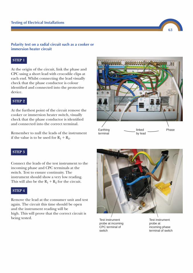
Testing of Electrical Installations
63
Polarity test on a radial circuit such as a cooker or immersion heater circuit
STEP 3
Connect the leads of the test instrument to theincoming phase and CPC terminals at theswitch. Test to ensure continuity. Theinstrument should show a very low reading.This will also be the R1 � R2 for the circuit.
STEP 4
Remove the lead at the consumer unit and testagain. The circuit this time should be openand the instrument reading will be high. This will prove that the correct circuit isbeing tested.
Earthing terminal
Phaselinked by lead
STEP 1
At the origin of the circuit, link the phase andCPC using a short lead with crocodile clips ateach end. Whilst connecting the lead visuallycheck that the phase conductor is colouridentified and connected into the protectivedevice.
STEP 2
At the furthest point of the circuit remove thecooker or immersion heater switch, visuallycheck that the phase conductor is identifiedand connected into the correct terminal.
Remember to null the leads of the instrumentif the value is to be used for R1 � R2.
Test instrument probe at incoming phase terminal of switch
Test instrument probe at incoming CPC terminal of switch
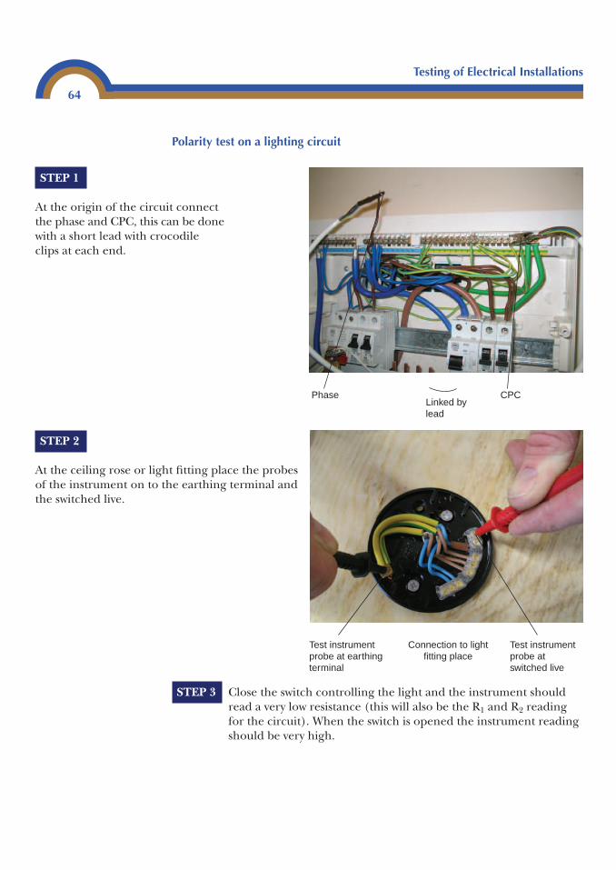
Testing of Electrical Installations
64
Polarity test on a lighting circuit
STEP 1
At the origin of the circuit connectthe phase and CPC, this can be donewith a short lead with crocodileclips at each end.
STEP 2
At the ceiling rose or light fitting place the probesof the instrument on to the earthing terminal andthe switched live.
STEP 3 Close the switch controlling the light and the instrument shouldread a very low resistance (this will also be the R1 and R2 readingfor the circuit). When the switch is opened the instrument readingshould be very high.
Phase CPCLinked by lead
Test instrument probe at earthing terminal
Test instrument probe at switched live
Connection to lightfitting place
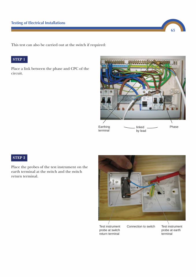
Testing of Electrical Installations
65
This test can also be carried out at the switch if required:
STEP 1
Place a link between the phase and CPC of thecircuit.
STEP 2
Place the probes of the test instrument on theearth terminal at the switch and the switchreturn terminal.
Earthing terminal
Phaselinked by lead
Test instrument probe at switch return terminal
Test instrument probe at earth terminal
Connection to switch
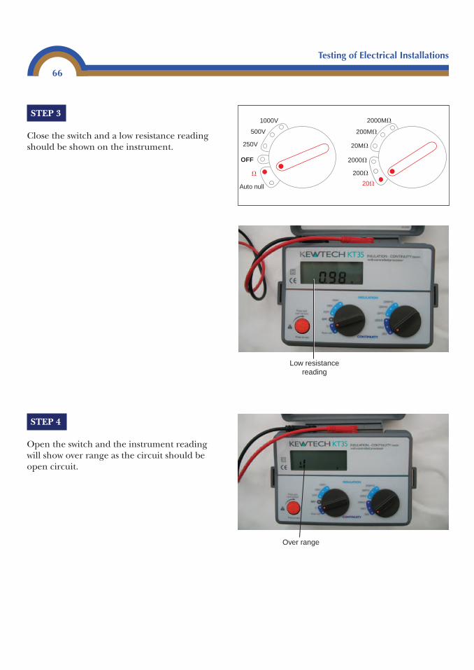
Testing of Electrical Installations
66
STEP 3
Close the switch and a low resistance readingshould be shown on the instrument.
STEP 4
Open the switch and the instrument readingwill show over range as the circuit should beopen circuit.
Over range
1000V
500V
250V
Auto null
OFF
�
2000M�
2000�
200M�
200�
20M�
20�
Low resistancereading
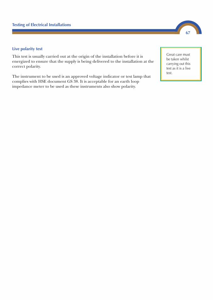
Testing of Electrical Installations
67
Live polarity test
This test is usually carried out at the origin of the installation before it isenergized to ensure that the supply is being delivered to the installation at thecorrect polarity.
The instrument to be used is an approved voltage indicator or test lamp thatcomplies with HSE document GS 38. It is acceptable for an earth loopimpedance meter to be used as these instruments also show polarity.
Great care must be taken whilstcarrying out thistest as it is a livetest.
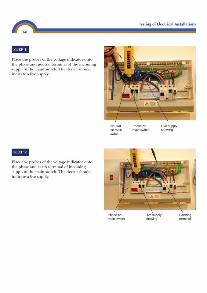
Testing of Electrical Installations
68
STEP 1
Place the probes of the voltage indicator ontothe phase and neutral terminal of the incomingsupply at the main switch. The device shouldindicate a live supply.
STEP 2
Place the probes of the voltage indicator ontothe phase and earth terminal of incomingsupply at the main switch. The device shouldindicate a live supply.
Live supply showing
Phase on main switch
Neutral on main switch
Phase on main switch
Live supply showing
Earthing terminal
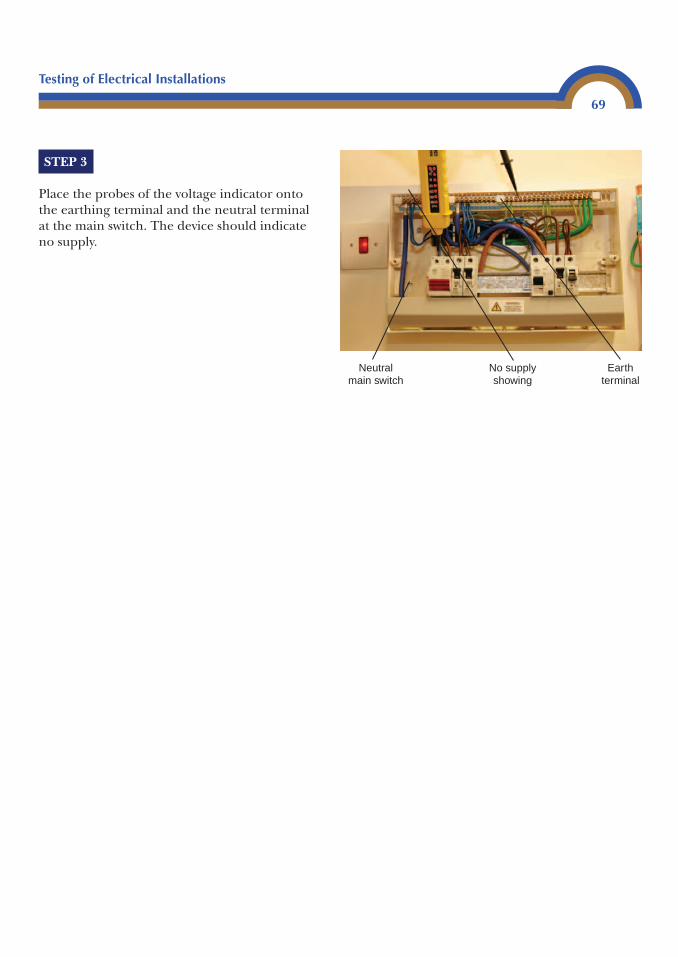
Testing of Electrical Installations
69
Neutralmain switch
No supplyshowing
Earthterminal
STEP 3
Place the probes of the voltage indicator ontothe earthing terminal and the neutral terminalat the main switch. The device should indicateno supply.
Testing of Electrical Installations
70
Earth electrode testing
Earth fault loop impedance tester
For many installations the resistance of the earth electrode can be measuredusing an earth fault loop impedance test instrument. It is perfectly acceptableto use this type of instrument on a TT system where reasonably highresistance values could be expected.
The test is performed in exactly the same way as the external earth fault loopZe test.
STEP 1 Isolate the installation.
STEP 2 Ensure that the earthing conductor is correctly terminated at theearth electrode.
STEP 3 Disconnect the earthing conductor from the main earthingterminal.
STEP 4 Connect a lead of the earth fault loop meter to the disconnectedearthing terminal.
STEP 5 Place the probe of the other lead on to the incoming phaseconductor at the supply side of the main switch and carry out thetest.
STEP 6 Record the result.
STEP 7 Reconnect the earthing conductor and leave the installation in safeworking condition.
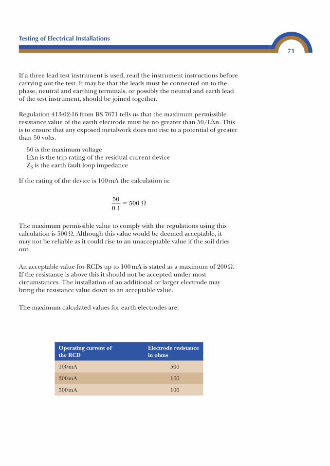
Testing of Electrical Installations
71
If a three lead test instrument is used, read the instrument instructions beforecarrying out the test. It may be that the leads must be connected on to thephase, neutral and earthing terminals, or possibly the neutral and earth leadof the test instrument, should be joined together.
Regulation 413-02-16 from BS 7671 tells us that the maximum permissibleresistance value of the earth electrode must be no greater than 50/IΔn. Thisis to ensure that any exposed metalwork does not rise to a potential of greaterthan 50 volts.
50 is the maximum voltageIΔn is the trip rating of the residual current deviceZS is the earth fault loop impedance
If the rating of the device is 100 mA the calculation is:
The maximum permissible value to comply with the regulations using thiscalculation is 500 Ω. Although this value would be deemed acceptable, it may not be reliable as it could rise to an unacceptable value if the soil driesout.
An acceptable value for RCDs up to 100 mA is stated as a maximum of 200 Ω.If the resistance is above this it should not be accepted under mostcircumstances. The installation of an additional or larger electrode may bring the resistance value down to an acceptable value.
The maximum calculated values for earth electrodes are:
500 1
500.
� Ω
Operating current of Electrode resistancethe RCD in ohms
100mA 500
300mA 160
500mA 100
Testing of Electrical Installations
72
For special locations where the maximum touch voltage is 25 V the electroderesistance should be halved. Electrode tests should be carried out in the worstpossible conditions. The worst condition for an earth electrode is when thesoil is dry. Where lower values of earth electrode resistances are required, an earth electrode tester should be used.
Measurement using an earth electrode test instrument
This test requires the use of three electrodes: the earthing electrode undertest, a current electrode and a potential electrode.
STEP 1 The earthing electrode (E) should be driven into the ground inthe position that it is to be used. Attention should be paid to thelength of the electrode which is in the ground.
STEP 2 The current electrode (C2 spike) should be pushed into theground at a distance of ten times the depth of the electrode undertest away from it.
STEP 3 The potential electrode (P2) should be pushed into the groundmidway between E and C2.
STEP 4 The leads of the test instrument should be connected to theappropriate electrodes.
STEP 5 Measure the value of resistance.
STEP 6 Move P2 10% closer to C2.
STEP 7 Measure the value of resistance.
STEP 8 Move P2 back to 10% closer to E than the mid-point.
STEP 9 Measure the value of the resistance.
Testing of Electrical Installations
73
A calculation must now be carried out to find the percentage deviation of theresistance values.
Example 6
Three measurements are taken: 0.8 ohms, 0.86 ohms and 0.78 ohms. Thesemust now be added together and an average value calculated.
Total value of three readings � 2.44
Find the average:
The average value is 0.81 ohms.
Now find the highest difference between the average value and the measured values. Inthis case it will be 0.86 � 0.81 � 0.05.
The percentage of this value to the average value must now be found:
This value is higher than 5% of the average value and it is not advisable to accept, itas a percentage deviation of greater than 5% is deemed to be inaccurate. To overcomethis, the distance between the electrode under test (E) and the current spike (C2) shouldnow be increased and the first three tests repeated to obtain a more accurate reading.
If the required resistance value cannot be obtained by the use of a singleelectrode, additional electrodes may be added at a distance from the firstelectrode equal to its depth.
Earth fault loop impedance Ze
0.050.81
100 6.1%� �
2.443
0.81�
Ze is a measurement of the external earth fault impedance (resistance) of theinstallation. In other words, it is the measured resistance of the supplytransformer winding, the supply phase conductor, and the earth return pathof the supply. It is measured in ohms.
This is a live test and great care must be taken
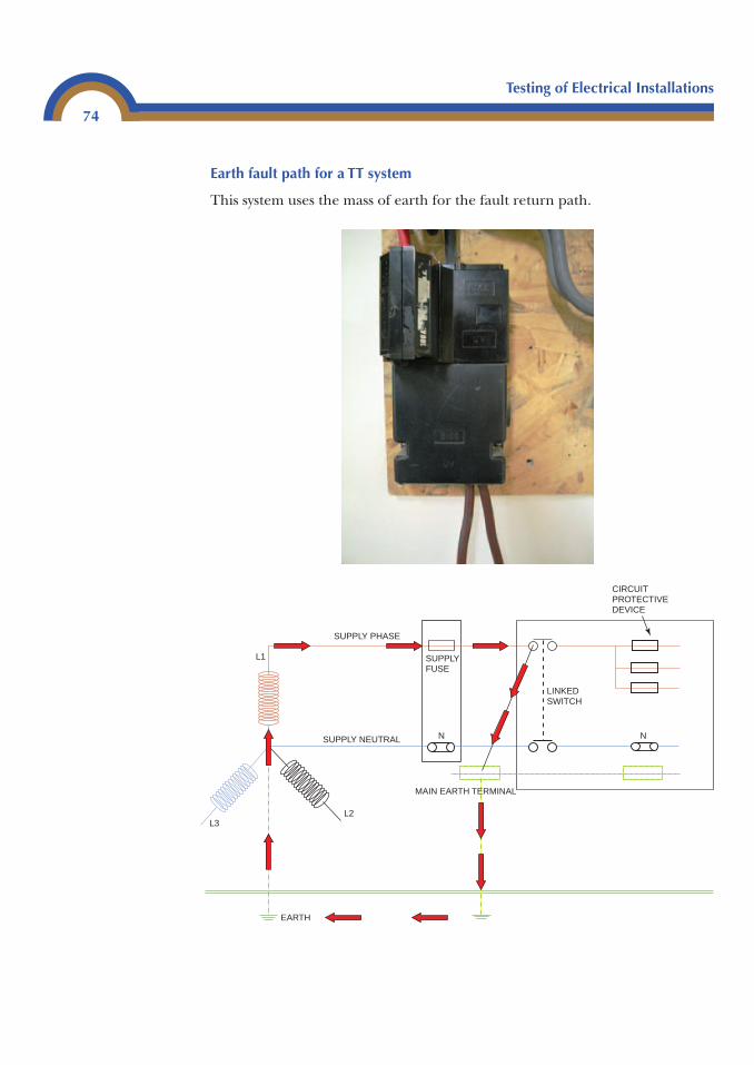
Testing of Electrical Installations
74
Earth fault path for a TT system
This system uses the mass of earth for the fault return path.
SUPPLY PHASE
SUPPLY FUSE
SUPPLY NEUTRAL
MAIN EARTH TERMINAL
L2
N N
LINKED SWITCH
L1
L3
EARTH
CIRCUIT PROTECTIVE DEVICE
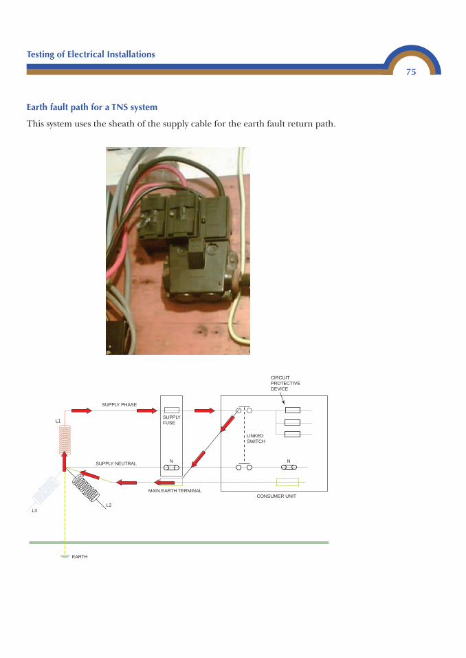
Earth fault path for a TNS system
This system uses the sheath of the supply cable for the earth fault return path.
MAIN EARTH TERMINAL
SUPPLY PHASE
SUPPLY FUSE
SUPPLY NEUTRAL
L2
N N
LINKED SWITCH
L1
L3
EARTH
CIRCUIT PROTECTIVE DEVICE
CONSUMER UNIT
Testing of Electrical Installations
75
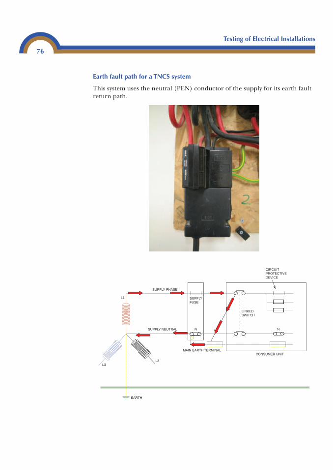
Testing of Electrical Installations
76
Earth fault path for a TNCS system
This system uses the neutral (PEN) conductor of the supply for its earth faultreturn path.
MAIN EARTH TERMINAL
SUPPLY PHASE
SUPPLY FUSE
SUPPLY NEUTRAL
L2
N N
LINKED SWITCH
L1
L3
EARTH
CIRCUIT PROTECTIVE DEVICE
CONSUMER UNIT
Testing of Electrical Installations
77
To carry out this test correctly the installation should be isolated from thesupply and the main earth disconnected from the main earth terminal(MET). This is to avoid the possibility of parallel paths through any earthedmetalwork within the installation.
Often in industrial and commercial installations – where isolation may beimpossible due to the building being in use – the only time that this test canbe carried out with the main earthing conductor disconnected, is during theinitial verification. It is important that the Ze with the earthing conductor isdisconnected during the initial verification as this will give a reference valuefor the life of the installation. If, during subsequent tests, the earthingconductor cannot be disconnected, a test can still be carried out but theparallel paths should give a lower impedance value. If a higher value isrecorded it will indicate a deterioration of the supply earth.
The instrument used for this test is an earth fault loop impedance meter, andit is important that the person using the instrument has read and understoodthe operating instructions. There are many types of test instruments on themarket and they all have their own characteristics.
Some instruments have three leads which must be connected to enable thistest to be carried out correctly. Some instruments require that the leads areconnected to the phase, neutral and earth of the circuit to be tested. Otherinstruments require the phase lead to be connected to the phase conductorand the earth and neutral leads to be connected to the earthing conductor ofthe circuit to be tested (it is important to read the instructions of the instrumentbeing used).
If using a two-lead instrument it should be set on Ze. One lead should beconnected to the main earthing conductor and the other to the incomingphase on the supply side of the main switch.
Probes can be used for this providing they meet the requirements of GS 38, i.e.:
• Insulated• Fused• Finger guards• Maximum of 4 mm exposed tips or retractable shrouds• Long enough to carry out test safely• Undamaged
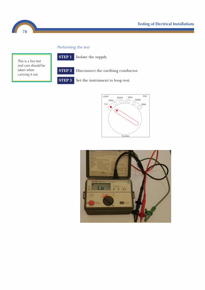
Testing of Electrical Installations
78
Performing the test
STEP 1 Isolate the supply.
STEP 2 Disconnect the earthing conductor.
STEP 3 Set the instrument to loop test.
20� 20k�
200�
2000�LOOP
2000A200A
Function
PSC
This is a live testand care should betaken whencarrying it out
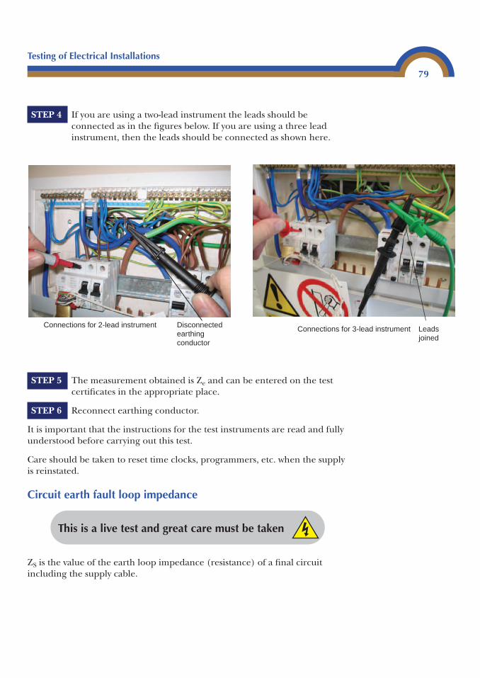
Testing of Electrical Installations
79
STEP 5 The measurement obtained is Ze and can be entered on the testcertificates in the appropriate place.
STEP 6 Reconnect earthing conductor.
It is important that the instructions for the test instruments are read and fullyunderstood before carrying out this test.
Care should be taken to reset time clocks, programmers, etc. when the supplyis reinstated.
Circuit earth fault loop impedance
This is a live test and great care must be taken
Disconnected earthing conductor
Connections for 2-lead instrument Leads joined
Connections for 3-lead instrument
STEP 4 If you are using a two-lead instrument the leads should beconnected as in the figures below. If you are using a three leadinstrument, then the leads should be connected as shown here.
ZS is the value of the earth loop impedance (resistance) of a final circuitincluding the supply cable.
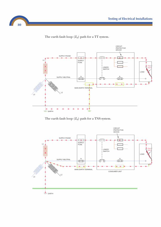
Testing of Electrical Installations
80
SUPPLY PHASE
SUPPLY FUSE
SUPPLY NEUTRAL
MAIN EARTH TERMINAL
L2
N N
LOAD
FAULT PATHLINKED
SWITCH
L1
L3
EARTH
CIRCUIT PROTECTIVE DEVICE
The earth fault loop (ZS) path for a TT system.
The earth fault loop (ZS) path for a TNS system.
MAIN EARTH TERMINAL
SUPPLY PHASE
SUPPLY FUSE
SUPPLY NEUTRAL
L2
N N
LOAD
FAULT PATH
LINKED SWITCH
L1
L3
EARTH
CIRCUIT PROTECTIVE DEVICE
CONSUMER UNIT
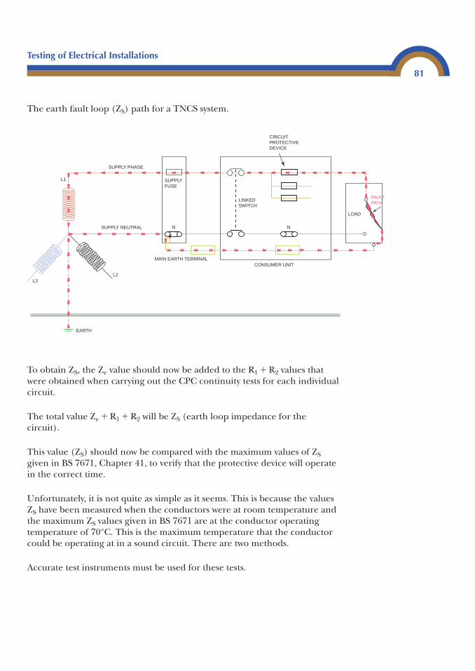
Testing of Electrical Installations
81
The earth fault loop (ZS) path for a TNCS system.
To obtain ZS, the Ze value should now be added to the R1 � R2 values thatwere obtained when carrying out the CPC continuity tests for each individualcircuit.
The total value Ze � R1 � R2 will be ZS (earth loop impedance for the circuit).
This value (ZS) should now be compared with the maximum values of ZSgiven in BS 7671, Chapter 41, to verify that the protective device will operatein the correct time.
Unfortunately, it is not quite as simple as it seems. This is because the valuesZS have been measured when the conductors were at room temperature andthe maximum ZS values given in BS 7671 are at the conductor operatingtemperature of 70°C. This is the maximum temperature that the conductorcould be operating at in a sound circuit. There are two methods.
Accurate test instruments must be used for these tests.
MAIN EARTH TERMINAL
SUPPLY PHASE
SUPPLY FUSE
SUPPLY NEUTRAL
L2
N N
LOAD
FAULT PATH
LINKED SWITCH
L1
L3
EARTH
CIRCUIT PROTECTIVE DEVICE
CONSUMER UNIT
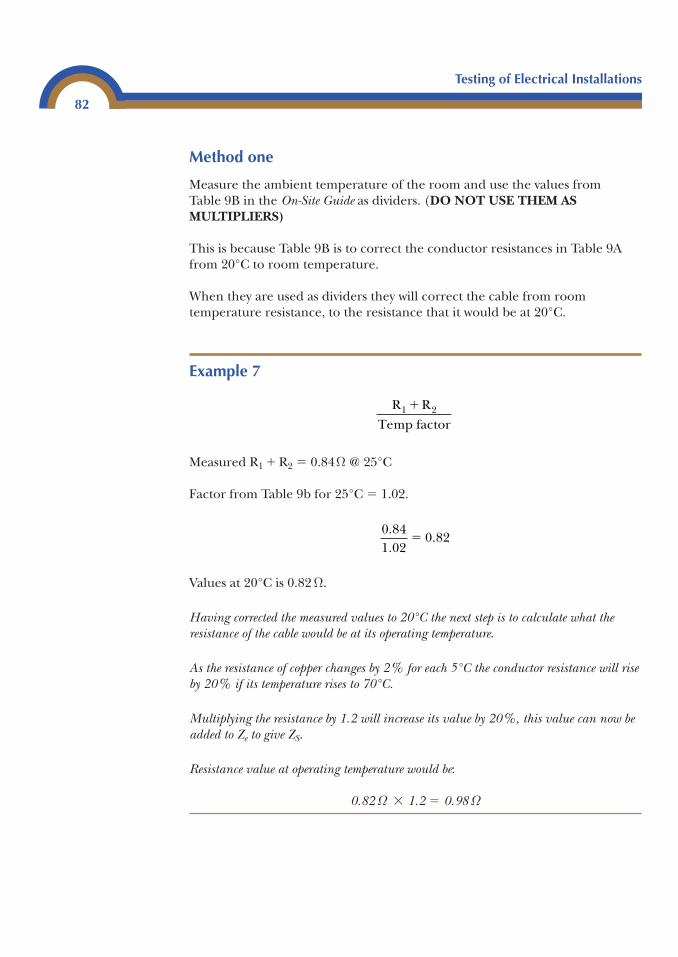
Testing of Electrical Installations
82
Method one
Measure the ambient temperature of the room and use the values from Table 9B in the On-Site Guide as dividers. (DO NOT USE THEM ASMULTIPLIERS)
This is because Table 9B is to correct the conductor resistances in Table 9Afrom 20°C to room temperature.
When they are used as dividers they will correct the cable from roomtemperature resistance, to the resistance that it would be at 20°C.
Example 7
Measured R1 � R2 � 0.84Ω @ 25°C
Factor from Table 9b for 25°C � 1.02.
Values at 20°C is 0.82 Ω.
Having corrected the measured values to 20°C the next step is to calculate what theresistance of the cable would be at its operating temperature.
As the resistance of copper changes by 2% for each 5°C the conductor resistance will riseby 20% if its temperature rises to 70°C.
Multiplying the resistance by 1.2 will increase its value by 20%, this value can now beadded to Ze to give ZS.
Resistance value at operating temperature would be:
0.82 Ω � 1.2 � 0.98 Ω
0 841 02
0 82..
.�
R RTemp factor
1 2 �
Testing of Electrical Installations
83
Example 8
The Ze of an installation is 0.6 Ω. A circuit has been installed using twin andCPC 70°C thermoplastic (pvc) cable. The room temperature is 25°C and themeasured R1 � R2 value is 0.48Ω. The circuit is protected by a BS EN 6089816A type B device.
Correct the cable resistance to 20°C by using factor from Table 9B On-SiteGuide.
Adjust this value to conductor operating temperature by increasing it by 20%.
0.47 � 1.2 � 0.56 Ω
Add this value to installation Ze to find ZS.
0.56 � 0.6 � 1.16 Ω
This value can now be compared directly with the maximum value ZS for a 16A type Bprotective device. This value is 3Ω and can be found in Table 41B2 in BS 7671.
To comply with the regulations the actual value 1.16 Ω is acceptable as it is less than 3 Ω.
Method two
Measure the resistance of earth fault loop impedance at the furthest point of the circuit using the correct instrument (remember the furthest point is the endof the circuit, not necessarily the furthest distance from the distribution board). Recordthe value obtained onto the test result schedule.
This measurement cannot be compared directly with the values from BS 7671because the operating temperature of the conductors and the ambienttemperature of the room are unknown.
0.481.02
0.47� Ω
Testing of Electrical Installations
84
This method is useful for a periodic test where existing test results are available.If the measured value is higher than previous results it will indicate that there isa possible deterioration of the earth loop impedance of the circuit.
The usual method to check that the measured ZS is acceptable is to use therule of thumb method.
First look in the correct table in Chapter 41 of BS 7671 for the maximumpermissible ZS of the protective device for the circuit being tested.
Use three-quarters of this value and compare it with the measured value.Providing the measured value is the lowest the circuit will comply.
More information on this can be found in Chapter 5 (Protective devices).
Performing the tests
This is a live test and great care must be taken
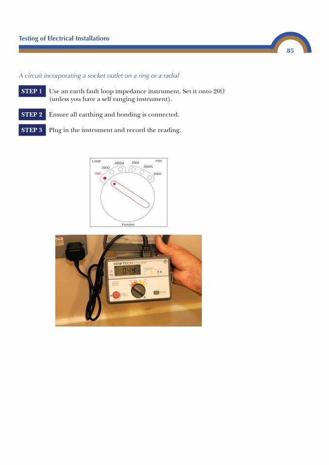
Testing of Electrical Installations
85
A circuit incorporating a socket outlet on a ring or a radial
STEP 1 Use an earth fault loop impedance instrument. Set it onto 20Ω(unless you have a self ranging instrument).
STEP 2 Ensure all earthing and bonding is connected.
STEP 3 Plug in the instrument and record the reading.
20� 20k�
200�
2000�LOOP
2000A200A
Function
PSC
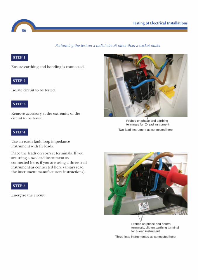
Testing of Electrical Installations
86
Performing the test on a radial circuit other than a socket outlet
STEP 1
Ensure earthing and bonding is connected.
STEP 2
Isolate circuit to be tested.
STEP 3
Remove accessory at the extremity of thecircuit to be tested.
STEP 4
Use an earth fault loop impedanceinstrument with fly leads.
Place the leads on correct terminals. If youare using a two-lead instrument asconnected here; if you are using a three-leadinstrument as connected here (always readthe instrument manufacturers instructions).
STEP 5
Energize the circuit.
Probes on phase and earthing terminals for 2-lead instrument
Two-lead instrument as connected here
Probes on phase and neutralterminals, clip on earthing terminal for 3-lead instrument
Three-lead instrumented as connected here
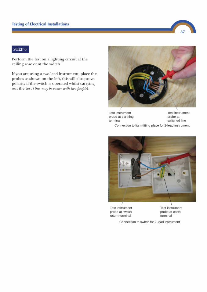
Testing of Electrical Installations
87
STEP 6
Perform the test on a lighting circuit at theceiling rose or at the switch.
If you are using a two-lead instrument, place theprobes as shown on the left, this will also provepolarity if the switch is operated whilst carryingout the test (this may be easier with two people).
Test instrument probe at earthing terminal
Test instrument probe at switched line
Connection to light-fitting place for 2-lead instrument
Test instrument probe at switch return terminal
Test instrument probe at earth terminal
Connection to switch for 2-lead instrument
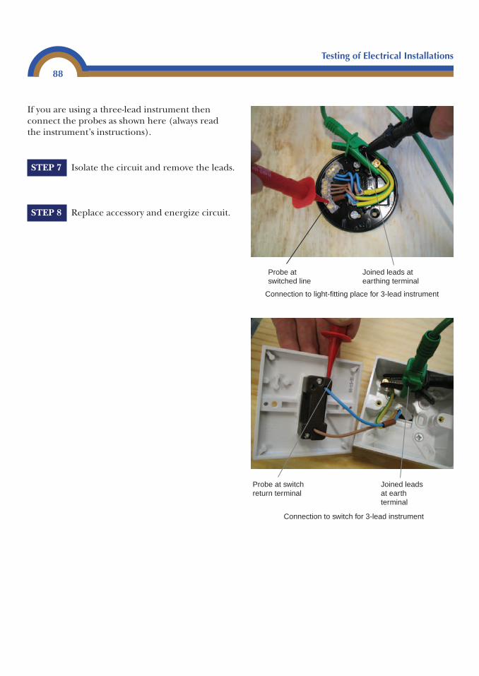
Testing of Electrical Installations
88
If you are using a three-lead instrument thenconnect the probes as shown here (always readthe instrument’s instructions).
STEP 7 Isolate the circuit and remove the leads.
STEP 8 Replace accessory and energize circuit.
Joined leads at earthing terminal
Probe at switched line
Connection to light-fitting place for 3-lead instrument
Joined leads at earth terminal
Probe at switch return terminal
Connection to switch for 3-lead instrument
Testing of Electrical Installations
89
Example 9
A ring final circuit is protected by a 30A BS3036 semi-enclosed rewirable fuseand the measured ZS is 0.96 Ω.
As this is a ring final circuit, the disconnection time has to be 0.4 seconds. From Table41B1 in BS 7671 the maximum ZS for a 30A rewirable fuse is 1.14 Ω.
Three-quarters of this value must now be calculated, this can be achieved by multiplyingit by 0.75.
1.14 � 0.75 � 0.85 Ω
The measured value for the circuit must now be lower than the corrected value if it is tocomply with BS 7671.
Measured value 0.96 ΩCorrected value 0.85 Ω
The measured value of ZS is higher; therefore, the circuit will not comply.
Option one is the preferred method because it will give an accurate value whereas the test in Option two will include parallel paths and because of this will often give lowerreadings.
Option one should always be used for an initial verification as the first reading will beused as a benchmark to be compared with results taken in future periodic tests.
If, on a periodic inspection using Option two, a higher test result is obtained than onthe initial verification, this would indicate that the circuit is deteriorating and thatfurther investigation would be required.
The methods described here must be fully understood by anyone who isintending to sit the City and Guilds 2391 exam on inspection and testing ofelectrical installations.
However! Providing that the ambient temperature is between 10°C and 20°Cthere is a much simpler way to check the results when you are actuallyworking on site testing. The On-Site Guide and Guidance Note 3 informationcontain tables which are already corrected for conductor operating current
Testing of Electrical Installations
90
and ambient temperature. In the On-Site Guide these tables can be found inAppendix 2 (Table 2A to Table 2D). These tables can also be used where theCPC is of a different cross-sectional area than the live conductors.
These values are slightly more favourable than the rule-of-thumb method, asthey are at approximately 80% of values given in BS 7671 and are perfectlyacceptable (remember, however, that the previous methods described must also beunderstood).
Example 10
A circuit supplying a fixed load is protected by a 20A BS 3036 fuse and themeasured ZS is 2.32 Ω. The circuit CPC is 1.5 mm2.
As this circuit is supplying a fixed load the maximum permitted disconnectiontime is 5 seconds.
The table that should be used is 2A(ii) from the On-Site Guide. Using this table it canbe seen that for a 20A device protecting a circuit with a 1.5 mm2 CPC the maximumpermissible ZS is 3.2 Ω. As the measured ZS is lower than the maximum permitted, thecircuit complies with the Regulations.
Example 11
A circuit supplying a cooker outlet which incorporates a socket outlet protectedby a 45A BS 1361 fuse, has a measured ZS of 0.4 Ω. The CPC is 4 mm2.
As this circuit has a socket outlet on it, the disconnection time would be 0.4 seconds.
The table to use for this circuit is 2C(i) from the On-Site Guide and the maximumpermitted ZS is 0.48 Ω. This circuit will comply.
Example 12
A circuit supplying a lighting circuit protected by a 6A type C BS 60898 protectivedevice has a measured ZS of 2.9 Ω.
Testing of Electrical Installations
91
It should be remembered that miniature circuit breakers will operate at 0.1 secondsproviding that the measured ZS is equal to or lower than the values given in the tables. We do not have to worry about 0.4 or 5 second disconnection times for thesedevices.
The table to use for this example is 2D in the On-Site Guide, the maximum permitted ZSis 3.2 Ω. The measured value of 2.9 Ω is lower than the maximum permitted, therefore,this circuit would comply.
Remember that the values in GN3 and the On-Site Guide are corrected fortemperatures between 10°C and 20°C and no other calculation is requiredproviding the ambient temperature is between these values.
If the ambient temperature is below 10°C or above 20°C then correctionfactors from Table 2E of the On-Site Guide must be used as follows.
Using Example 9, a circuit supplying a fixed load is protected by a 20A BS3036 fuse and the measured ZS is 2.32 Ω. The circuit CPC is 1.5 mm2, and theambient temperature is 23°C.
As this circuit is supplying a fixed load, the maximum permitteddisconnection time is 5 seconds.
The table that should be used is 2A(ii) from the On-Site Guide. Using the tableit can be seen that for a 20A device protecting a circuit with a 1.5 mm2 CPC,the maximum permitted ZS is 3.20 Ω.
Now the temperature has to be taken into account.
Using Table 2E from Appendix 2 of the On-Site Guide it can be seen that thenearest value to the temperature which was measured (23°) is 25°C (alwaysround up to be on the safe side). The correction factor for 25°C is 1.06.
This value (1.06) is now used as a multiplier to the maximum permitted ZS(3.20 Ω) to calculate the maximum ZS for the circuit at 25°C
3.20 � 1.06 � 3.39 Ω
This is the maximum measured ZS permissible for the circuit at 25°C.
Testing of Electrical Installations
92
Prospective fault current test
A prospective fault current test instrument is normally combined with anearth loop impedance test instrument, the measured value is normally shownin kA (kilo amps).
Regulations 434-02-01 and 713-12-01 require that the prospective short circuitcurrent and the prospective earth fault current are determined. Oncedetermined, the highest value must of course be recorded.
A prospective short circuit current is the maximum current that could flowbetween phase and neutral on a single-phase supply or between phaseconductors on a three-phase supply.
A prospective earth fault current is the maximum current that could flowbetween live conductors and earth.
The higher of these values is known as prospective fault current.
The highest prospective fault current will be at the origin of the installationand must be measured as close to the meter position as possible, usually at themain switch for the installation. It is measured between phase and neutral.
This can be done by:
• Enquiry to the supplier• Calculation• Measurement
Enquiry
This is a matter of a phone call to the electricity supplier of the installation.They will tell you the maximum PFC. Usually this is a lot higher than the valuewill actually be, but if you use this value you will be on the safe side.
Calculation
The PFC can only be calculated on a TNCS system. This is because the neutralof the supply is used as a Protective earth and neutral (PEN) conductor.
This is a live test and great care must be taken
Testing of Electrical Installations
93
When the earth fault loop impedance is measured, the value measured is inohms. To convert this value to prospective short circuit current we must usethe following equation:
It is important to remember that the open circuit voltage of the supplytransformer is used UOC 240 V (BS 7671, Appendix 3).
Example 13
Ze is measured at 0.28 Ω
A useful tip is that when you have measured Ze on a TNCS system, set your instrumentto PFC and repeat the test. This will give you the value for PFC and save you doing thecalculation.
2400.28
857 amps�
PSCCVZ
Ie
� �
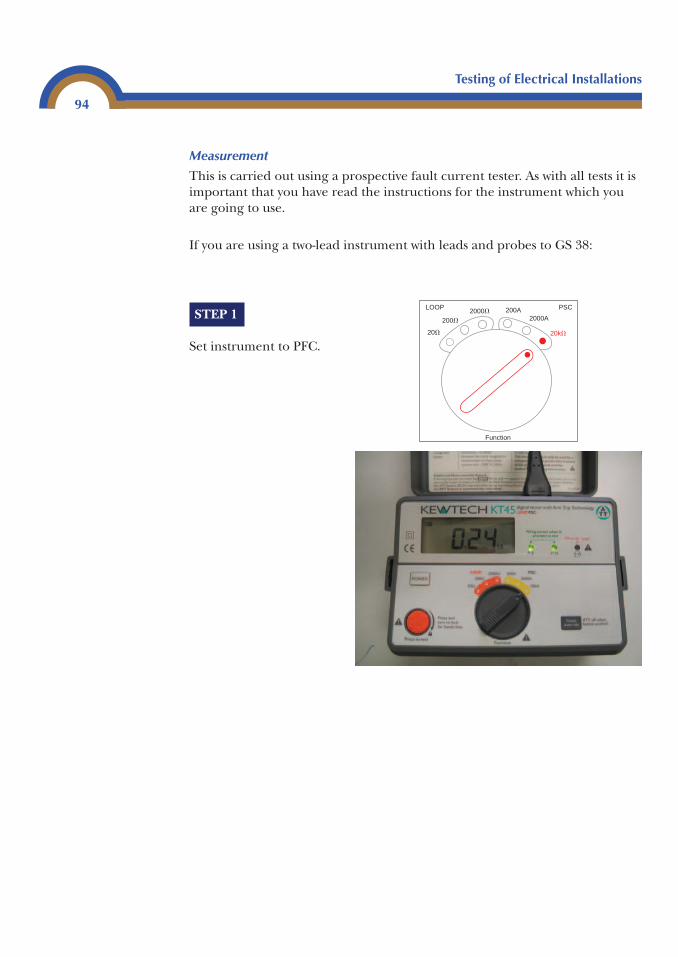
Testing of Electrical Installations
94
STEP 1
Set instrument to PFC.
Measurement
This is carried out using a prospective fault current tester. As with all tests it isimportant that you have read the instructions for the instrument which youare going to use.
If you are using a two-lead instrument with leads and probes to GS 38:
20� 20k�
200�
2000�2000A
200A
Function
PSCLOOP
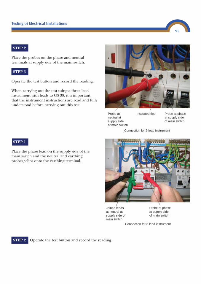
Testing of Electrical Installations
95
STEP 2
Place the probes on the phase and neutralterminals at supply side of the main switch.
STEP 3
Operate the test button and record the reading.
When carrying out the test using a three-leadinstrument with leads to GS 38, it is importantthat the instrument instructions are read and fullyunderstood before carrying out this test.
STEP 2 Operate the test button and record the reading.
STEP 1
Place the phase lead on the supply side of themain switch and the neutral and earthingprobes/clips onto the earthing terminal.
Insulated tipsProbe at neutral at supply side of main switch
Probe at phase at supply side of main switch
Connection for 2-lead instrument
Joined leads at neutral at supply side of main switch
Probe at phase at supply side of main switch
Connection for 3-lead instrument
Testing of Electrical Installations
96
If the supply system is a three-phase and neutral system then the highestcurrent that could flow in it will be between phases. Some instruments will notbe able to measure the high current that would flow under thesecircumstances.
Under these circumstances the measurement should be made between anyphase and neutral at the main switch and the measured value should bedoubled.
For your personal safety and the protection of your test equipment it isimportant to read and fully understand the instructions of your testinstrument before commencing this test.
Some PSCC (protective short-circuit current) instruments give the measuredvalue in ohms, not kA. If this is the case, a simple calculation, using ohms lawis all that is required.
Example 14
Measured value is 0.08Ω.
Remember to use UOC in this calculation (240 V)
It is important that the short circuit capacity of any protective devices fittedexceeds the maximum current that could flow at the point at which they arefitted.
When a measurement of PFC is taken as close to the supply intake as possible,and all protective devices fitted in the installation have a short circuit capacitythat is higher than the measured value, then Regulation 432-02-01 will besatisfied.
In a large installation where sub mains are used to supply distribution boardsit can be cost effective to measure the PFC at each board. The PFC will besmaller and could allow the use of a protective device with a lower shortcircuit rating. These will usually be less expensive.
Table 7.2A in the On-Site Guide gives rated short circuit capacities for devices.These values can also be obtained from manufacturer’s literature.
PSCC2400.08
3000 A� �
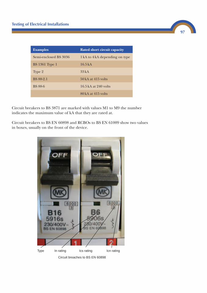
Testing of Electrical Installations
97
Circuit breakers to BS 3871 are marked with values M1 to M9 the numberindicates the maximum value of kA that they are rated at.
Circuit breakers to BS EN 60898 and RCBOs to BS EN 61009 show two valuesin boxes, usually on the front of the device.
Examples Rated short circuit capacity
Semi-enclosed BS 3036 1 kA to 4 kA depending on type
BS 1361 Type 1 16.5 kA
Type 2 33 kA
BS 88-2.1 50 kA at 415 volts
BS 88-6 16.5 kA at 240 volts
80 kA at 415 volts
Icn ratingIcs ratingIn ratingType
Circuit breaches to BS EN 60898
Testing of Electrical Installations
98
The square box will indicate the maximum current that the device couldinterrupt and still be reset . This is the Ics rating. The rectangular box willindicate the maximum current that the device can interrupt safely .This is the Icn rating.
If a value of fault current above the rated Isc rating of the device were to flowin the circuit, the device will no longer be serviceable and will have to bereplaced. A value of fault current above the Icn rating would be verydangerous and possibly result in an explosion causing major damage to thedistribution board/consumer’s unit.
Functional testing
All equipment must be tested to ensure that it operates correctly. All switches,isolators and circuit breakers must be manually operated to ensure that theyfunction correctly, also that they have been correctly installed and adjustedwhere adjustment is required.
Residual current device (RCD)
The instrument used for this test is an RCD tester, and it measures the time ittakes for the RCD to interrupt the supply of current flowing through it. Thevalue of measurement is either in seconds or milliseconds.
Before we get on to testing, let’s consider what types of RCDs there are, whatthey are used for, and where they should be used.
Types of RCD
Voltage operated
Voltage operated earth leakage current breakers (ELCBs) are not uncommonin older installations. This type of device became obsolete in the early 1980sand must not be installed in a new installation or alteration as they are nolonger recognized by BS 7671.
They are easily recognized as they have two earth connections, one for the earth electrode and the other for the installation earthing conductor. Themajor problem with voltage operated devices is that a parallel path in thesystem will probably stop it from operating.
These types of devices would normally have been used as earth faultprotection in a TT system.
60003
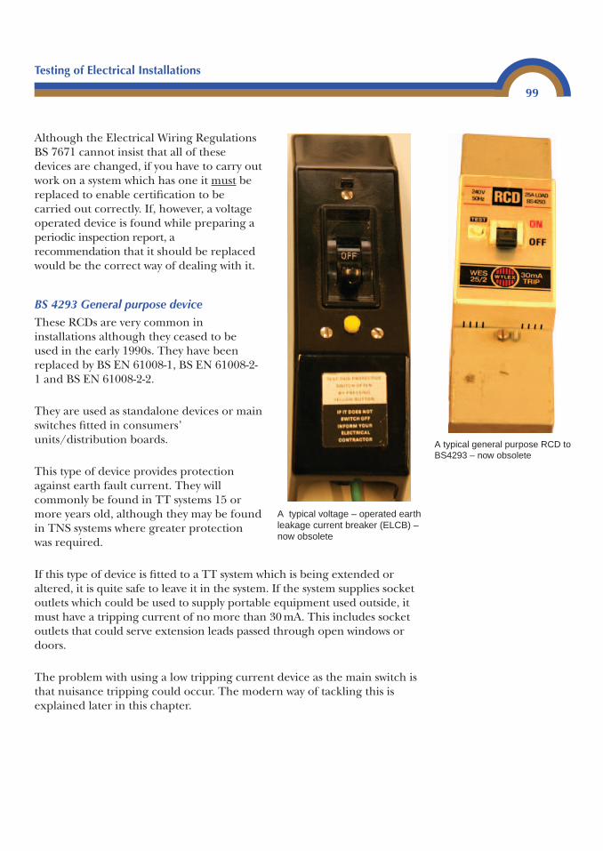
Although the Electrical Wiring RegulationsBS 7671 cannot insist that all of these devices are changed, if you have to carry outwork on a system which has one it must bereplaced to enable certification to be carried out correctly. If, however, a voltageoperated device is found while preparing aperiodic inspection report, arecommendation that it should be replacedwould be the correct way of dealing with it.
BS 4293 General purpose device
These RCDs are very common ininstallations although they ceased to beused in the early 1990s. They have beenreplaced by BS EN 61008-1, BS EN 61008-2-1 and BS EN 61008-2-2.
They are used as standalone devices or mainswitches fitted in consumers’units/distribution boards.
This type of device provides protectionagainst earth fault current. They willcommonly be found in TT systems 15 ormore years old, although they may be foundin TNS systems where greater protectionwas required.
If this type of device is fitted to a TT system which is being extended or altered, it is quite safe to leave it in the system. If the system supplies socketoutlets which could be used to supply portable equipment used outside, itmust have a tripping current of no more than 30 mA. This includes socketoutlets that could serve extension leads passed through open windows ordoors.
The problem with using a low tripping current device as the main switch isthat nuisance tripping could occur. The modern way of tackling this isexplained later in this chapter.
Testing of Electrical Installations
99
A typical general purpose RCD toBS4293 – now obsolete
A typical voltage – operated earth leakage current breaker (ELCB) – now obsolete
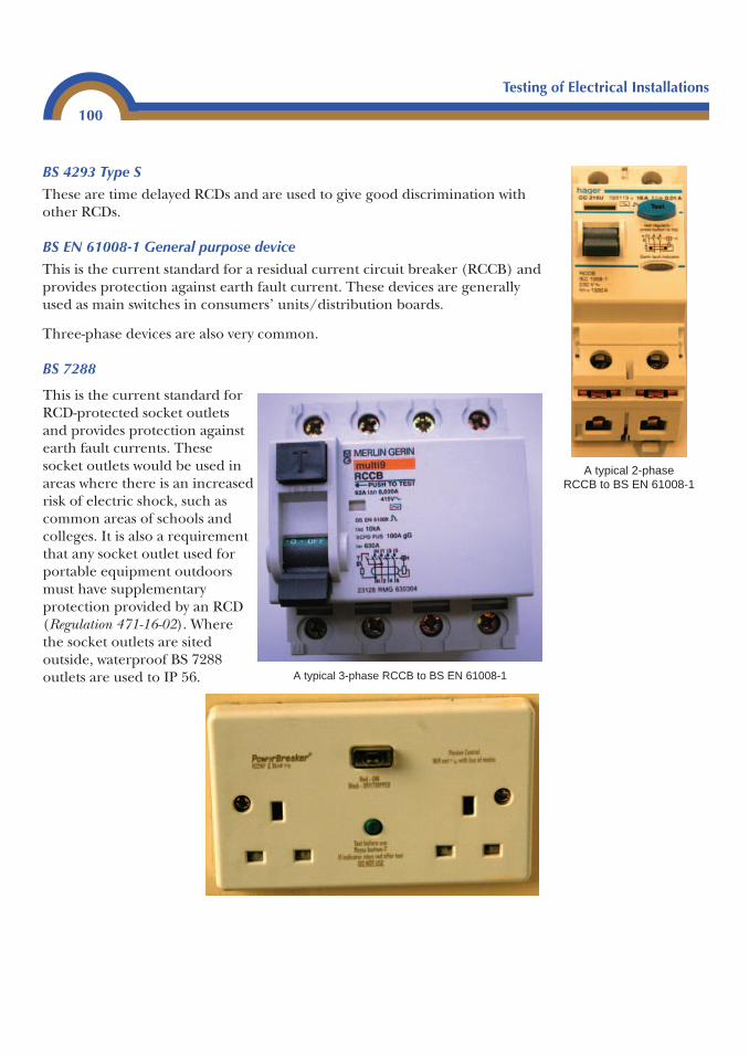
Testing of Electrical Installations
100
BS 4293 Type S
These are time delayed RCDs and are used to give good discrimination withother RCDs.
BS EN 61008-1 General purpose device
This is the current standard for a residual current circuit breaker (RCCB) andprovides protection against earth fault current. These devices are generallyused as main switches in consumers’ units/distribution boards.
Three-phase devices are also very common.
BS 7288
A typical 2-phaseRCCB to BS EN 61008-1
A typical 3-phase RCCB to BS EN 61008-1
This is the current standard forRCD-protected socket outletsand provides protection againstearth fault currents. Thesesocket outlets would be used inareas where there is an increasedrisk of electric shock, such ascommon areas of schools andcolleges. It is also a requirementthat any socket outlet used forportable equipment outdoorsmust have supplementaryprotection provided by an RCD(Regulation 471-16-02). Wherethe socket outlets are sitedoutside, waterproof BS 7288outlets are used to IP 56.
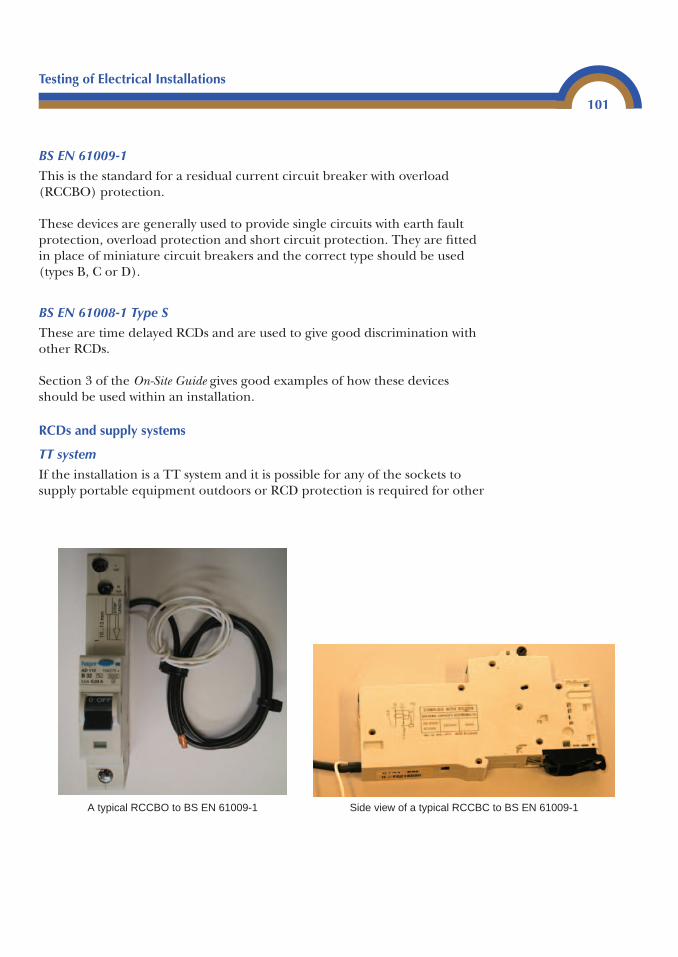
Testing of Electrical Installations
101
BS EN 61009-1
This is the standard for a residual current circuit breaker with overload(RCCBO) protection.
These devices are generally used to provide single circuits with earth faultprotection, overload protection and short circuit protection. They are fittedin place of miniature circuit breakers and the correct type should be used(types B, C or D).
BS EN 61008-1 Type S
These are time delayed RCDs and are used to give good discrimination withother RCDs.
Section 3 of the On-Site Guide gives good examples of how these devicesshould be used within an installation.
RCDs and supply systems
TT system
If the installation is a TT system and it is possible for any of the sockets tosupply portable equipment outdoors or RCD protection is required for other
A typical RCCBO to BS EN 61009-1 Side view of a typical RCCBC to BS EN 61009-1
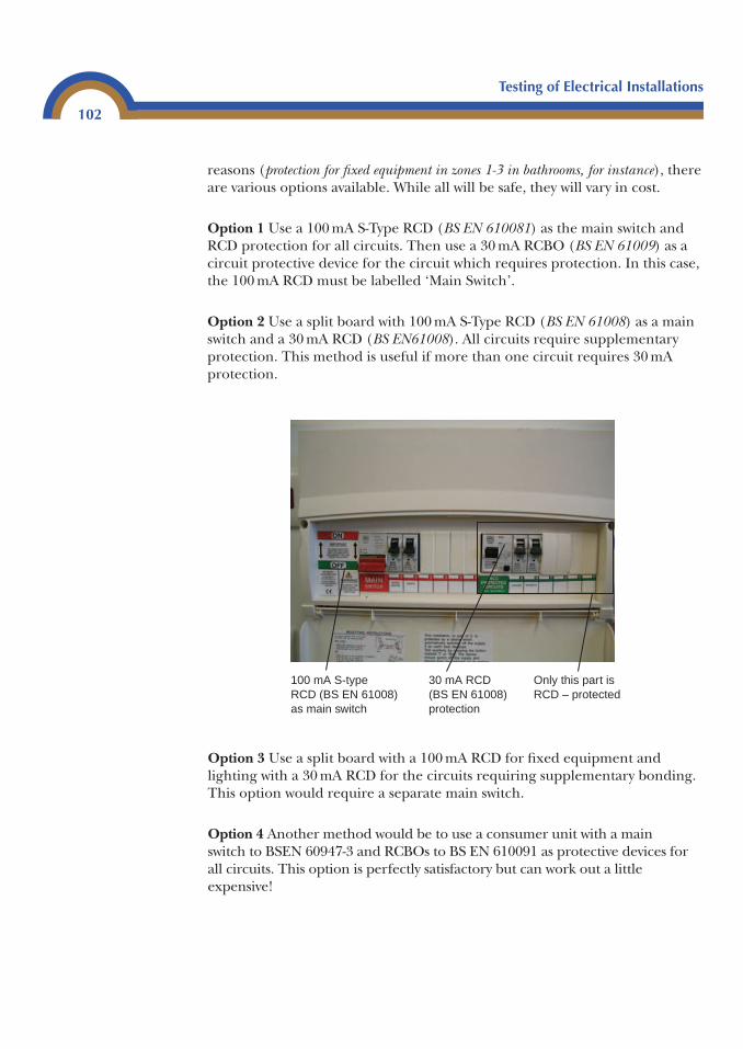
Testing of Electrical Installations
102
reasons (protection for fixed equipment in zones 1-3 in bathrooms, for instance), thereare various options available. While all will be safe, they will vary in cost.
Option 1 Use a 100 mA S-Type RCD (BS EN 610081) as the main switch andRCD protection for all circuits. Then use a 30 mA RCBO (BS EN 61009) as acircuit protective device for the circuit which requires protection. In this case,the 100 mA RCD must be labelled ‘Main Switch’.
Option 2 Use a split board with 100 mA S-Type RCD (BS EN 61008) as a mainswitch and a 30 mA RCD (BS EN61008). All circuits require supplementaryprotection. This method is useful if more than one circuit requires 30 mAprotection.
Option 3 Use a split board with a 100 mA RCD for fixed equipment andlighting with a 30 mA RCD for the circuits requiring supplementary bonding.This option would require a separate main switch.
Option 4 Another method would be to use a consumer unit with a main switch to BSEN 60947-3 and RCBOs to BS EN 610091 as protective devices forall circuits. This option is perfectly satisfactory but can work out a littleexpensive!
100 mA S-type RCD (BS EN 61008) as main switch
30 mA RCD (BS EN 61008) protection
Only this part is RCD – protected
Testing of Electrical Installations
103
TNS and TNCS systems
If the supply system was TNS or TNCS, Options 1 and 2 could be used. Butinstead of using a 100 mA S-Type RCD as a main switch, it could be substitutedfor a main switch to BS EN 60947-3.
Option 4 will remain pretty much the same but BS EN 60898 devices could beused where RCD protection is not required.
Testing of RCDs
The instrument to be used to carry out this test is an RCD tester, with leads tocomply with GS 38.
Voltage operated (ELCBs)
No test required as they should now be replaced.
BS 4293 RCDs
If this type of RCD is found on TT systems or other systems where there is ahigh value of earth fault impedance (Ze), the RCD tester should be pluggedinto the nearest socket or connected as close as possible to the RCD. Thetester should then be set at the rated tripping current of the RCD (IΔn); forexample, at 30 mA (be careful and do not mistake the tripping current for the currentrating of the device).
Before carrying outthe tests ensurethat all loads areremoved; failure todo this may resultin the readingsbeing inaccurate.
Remember that these are live tests and careshould be taken whilst carrying them out
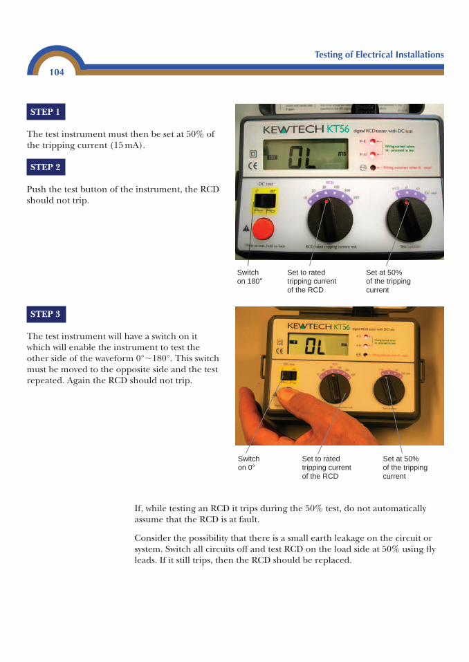
Testing of Electrical Installations
104
STEP 1
The test instrument must then be set at 50% ofthe tripping current (15 mA).
STEP 2
Push the test button of the instrument, the RCDshould not trip.
STEP 3
The test instrument will have a switch on itwhich will enable the instrument to test theother side of the waveform 0°�180°. This switchmust be moved to the opposite side and the testrepeated. Again the RCD should not trip.
Switch on 180°
Set to rated tripping current of the RCD
Set at 50% of the tripping current
Set at 50% of the tripping current
Set to rated tripping current of the RCD
Switch on 0°
If, while testing an RCD it trips during the 50% test, do not automaticallyassume that the RCD is at fault.
Consider the possibility that there is a small earth leakage on the circuit orsystem. Switch all circuits off and test RCD on the load side at 50% using flyleads. If it still trips, then the RCD should be replaced.
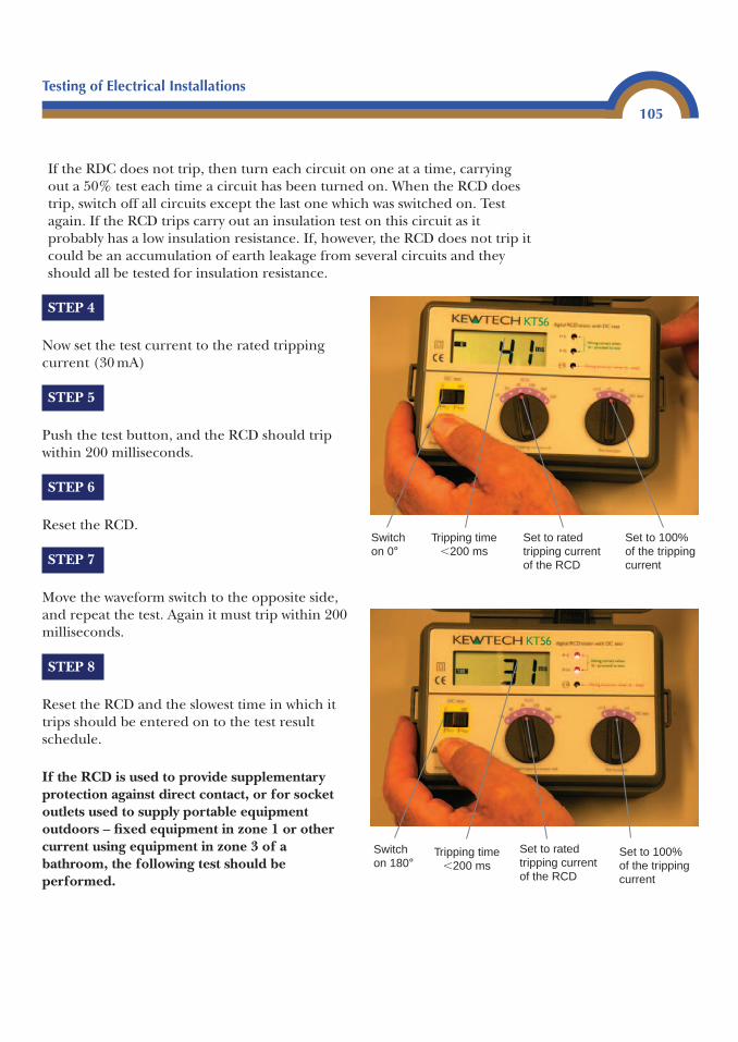
Testing of Electrical Installations
105
STEP 4
Now set the test current to the rated trippingcurrent (30 mA)
STEP 5
Push the test button, and the RCD should tripwithin 200 milliseconds.
STEP 6
Reset the RCD.
STEP 7
Move the waveform switch to the opposite side,and repeat the test. Again it must trip within 200milliseconds.
STEP 8
Reset the RCD and the slowest time in which ittrips should be entered on to the test resultschedule.
If the RCD is used to provide supplementaryprotection against direct contact, or for socketoutlets used to supply portable equipmentoutdoors – fixed equipment in zone 1 or othercurrent using equipment in zone 3 of abathroom, the following test should beperformed.
Set to rated tripping current of the RCD
Tripping time�200 ms
Switch on 180°
Set to 100% of the tripping current
Set to rated tripping current of the RCD
Set to 100% of the tripping current
Switch on 0°
Tripping time�200 ms
If the RDC does not trip, then turn each circuit on one at a time, carryingout a 50% test each time a circuit has been turned on. When the RCD doestrip, switch off all circuits except the last one which was switched on. Testagain. If the RCD trips carry out an insulation test on this circuit as itprobably has a low insulation resistance. If, however, the RCD does not trip itcould be an accumulation of earth leakage from several circuits and theyshould all be tested for insulation resistance.
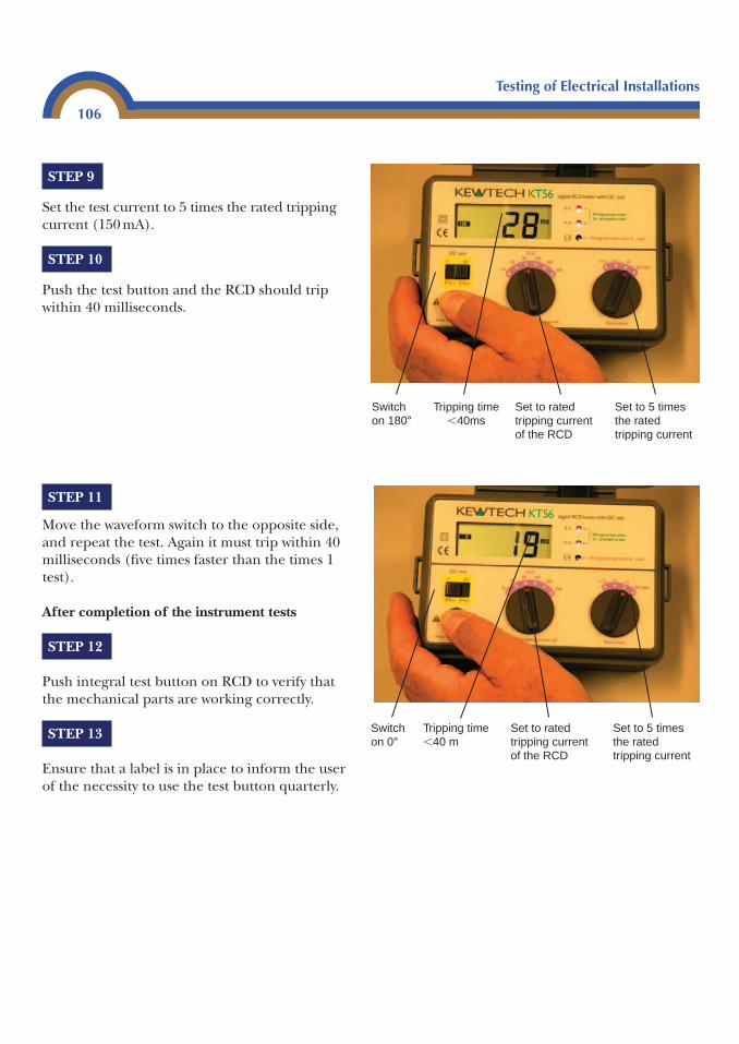
Testing of Electrical Installations
106
STEP 9
Set the test current to 5 times the rated trippingcurrent (150 mA).
STEP 10
Push the test button and the RCD should tripwithin 40 milliseconds.
STEP 11
Move the waveform switch to the opposite side,and repeat the test. Again it must trip within 40milliseconds (five times faster than the times 1test).
After completion of the instrument tests
STEP 12
Push integral test button on RCD to verify thatthe mechanical parts are working correctly.
STEP 13
Ensure that a label is in place to inform the userof the necessity to use the test button quarterly.
Tripping time�40ms
Set to 5 times the rated tripping current
Set to rated tripping current of the RCD
Switch on 180°
Set to rated tripping current of the RCD
Set to 5 times the rated tripping current
Tripping time�40 m
Switch on 0°
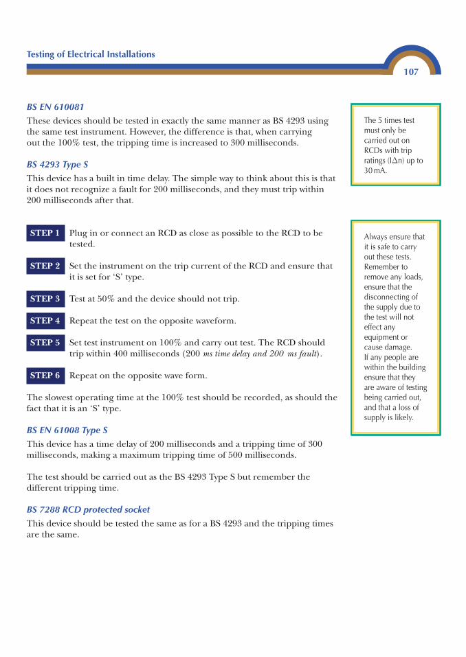
Testing of Electrical Installations
107
BS EN 610081
These devices should be tested in exactly the same manner as BS 4293 usingthe same test instrument. However, the difference is that, when carrying out the 100% test, the tripping time is increased to 300 milliseconds.
BS 4293 Type S
This device has a built in time delay. The simple way to think about this is thatit does not recognize a fault for 200 milliseconds, and they must trip within200 milliseconds after that.
STEP 1 Plug in or connect an RCD as close as possible to the RCD to betested.
STEP 2 Set the instrument on the trip current of the RCD and ensure thatit is set for ‘S’ type.
STEP 3 Test at 50% and the device should not trip.
STEP 4 Repeat the test on the opposite waveform.
STEP 5 Set test instrument on 100% and carry out test. The RCD shouldtrip within 400 milliseconds (200 ms time delay and 200 ms fault).
STEP 6 Repeat on the opposite wave form.
The slowest operating time at the 100% test should be recorded, as should thefact that it is an ‘S’ type.
BS EN 61008 Type S
This device has a time delay of 200 milliseconds and a tripping time of 300milliseconds, making a maximum tripping time of 500 milliseconds.
The test should be carried out as the BS 4293 Type S but remember thedifferent tripping time.
BS 7288 RCD protected socket
This device should be tested the same as for a BS 4293 and the tripping timesare the same.
The 5 times testmust only becarried out onRCDs with tripratings (IΔn) up to30 mA.
Always ensure thatit is safe to carryout these tests.Remember toremove any loads,ensure that thedisconnecting ofthe supply due tothe test will noteffect anyequipment orcause damage.If any people arewithin the buildingensure that theyare aware of testingbeing carried out,and that a loss ofsupply is likely.
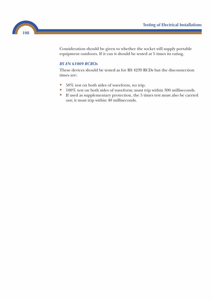
Consideration should be given to whether the socket will supply portableequipment outdoors. If it can it should be tested at 5 times its rating.
BS EN 61009 RCBOs
These devices should be tested as for BS 4239 RCDs but the disconnectiontimes are:
• 50% test on both sides of waveform, no trip.• 100% test on both sides of waveform; must trip within 300 milliseconds.• If used as supplementary protection, the 5 times test must also be carried
out; it must trip within 40 milliseconds.
Testing of Electrical Installations
108

Completion of testcertificates
3
The following pages detail the test certificates and itemized descriptions. Atthe end of the chapter further ‘Notes for Recipients’ can be found.
Minor Domestic Electrical Installation Works Certificate
This certificate is to be completed when additions to existing circuits havebeen carried out. For example, an additional lighting point or socket outlet.
If more than one circuit has been added to, then a separate Minor WorksCertificate must be issued for each modification.
These certificates vary slightly depending on which certification body hassupplied them; some require slightly more information than others. Theinformation required is as follows.
4
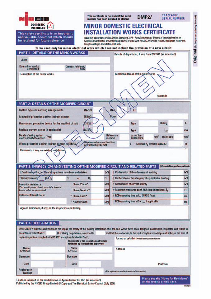
Client Name of the person ordering the work.Location/address The address at which the work is carried out.Date Completion of minor work.Description It is important to document exactly the work which has been
carried out.
Type of system TT, TNS, TNCS.
Method of protection against indirect contact This will usually be EEBAADS.
Overcurrent device for the circuit This is the type and size of device which is protecting the circuit on which the minor works has been carried out. If it is necessary to change the protective device, then anelectrical installation certificate is required. Not a Minor Works Certificate.
Residual current device Type, current rating and tripping value IΔn is required. If the addition to the circuit requires the fitting of an RCD, then an Electrical Installation Certificate is required for the RCD.
Details of wiring system used What type of wiring is it? For example, PVC,conduit, steel wire armour.
Reference method How has it been installed? See Appendix 4, BS 7671 forreference methods.
CSA of conductors What size are the conductors?Maximum disconnection time of the circuit Is it 5 seconds or 0.4 seconds?Maximum ZS What is the maximum ZS permitted to ensure that theprotective device operates in the correct time? These can be found in Part 4of BS 7671.
Circuit resistance What is the value of R1 � R2 or R2 if Table 41C of BS 7671is being used.
Confirmation of bonding Has bonding been installed? If not, this should bepointed out to the client, and identified in the comments section of thecertificate. It is still permissible to carry out minor works if bonding is not presentin the installation.
Confirmation of earthing Is the installation earthed? If not, then the workshould not be carried out and the client should be informed of the dangerthat this presents.
Minor Domestic Electrical Installation Works Certificate
111
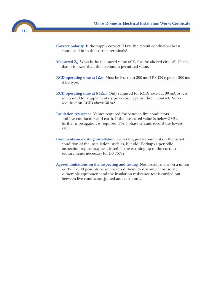
Correct polarity Is the supply correct? Have the circuit conductors beenconnected in to the correct terminals?
Measured ZS What is the measured value of ZS for the altered circuit? Checkthat it is lower than the maximum permitted value.
RCD operating time at IΔn Must be less than 300 ms if BS EN type, or 200 msif BS type.
RCD operating time at 5 IΔn Only required for RCDs rated at 30 mA or less,when used for supplementary protection against direct contact. Neverrequired on RCDs above 30 mA.
Insulation resistance Values required for between live conductors and live conductors and earth. If the measured value is below 2 MΩ,further investigation is required. For 3 phase circuits record the lowestvalue.
Comments on existing installation Generally, just a comment on the visualcondition of the installation; such as, is it old? Perhaps a periodicinspection report may be advised. Is the earthing up to the currentrequirements necessary for BS 7671?
Agreed limitations on the inspecting and testing Not usually many on a minorworks. Could possibly be where it is difficult to disconnect or isolatevulnerable equipment and the insulation resistance test is carried outbetween live conductors joined and earth only.
Minor Domestic Electrical Installation Works Certificate
112

This page intentionally left blank
Electrical Installation Certificate
115
Electrical Installation Certificate
This certificate is to be completed for a new circuit, a new installation, a rewiring and any circuit where the protective device has been changed.
In the case of a consumer’s unit change only, an Electrical InstallationCertificate would be required for the consumers unit and a PeriodicInspection Report should be completed for the existing installation.
A standard Electrical Installation Certificate can be used for any installation.However, if the work to be certificated is covered by building regulation, a Part P Certificate is available solely for this purpose. These certificatessimplify the paper work by including a schedule of inspection and a Scheduleof Test Results on the same document.
A Schedule of Test Results and a Schedule of Inspection must be completedto accompany an electrical installation certificate and a periodic inspectionreport.
These certificates vary slightly depending on which certification body hassupplied them, some require slightly more information than others. TheElectrical Installation Certificate and Particulars of Signatures to the ElectricalInstallation Certificate are typical of an electrical installation certificate. The information required is as follows.
This certification isrequired for a newinstallation orcircuit
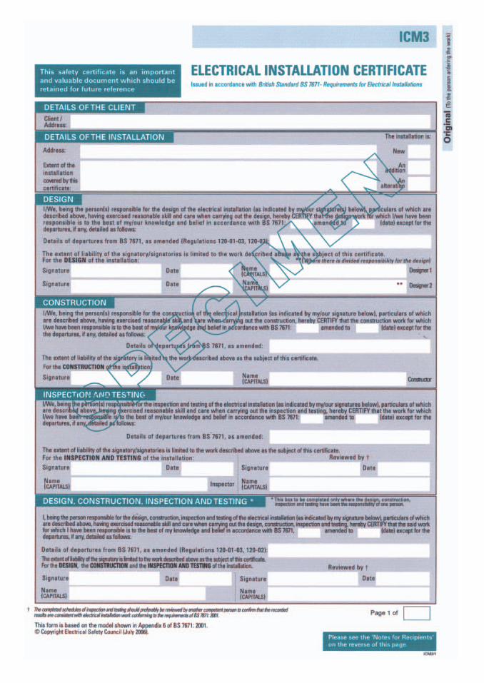
Details of client Name and address of the person ordering the work.
Location/address The address at which the work is carried out.
Details of the installation What part of the installation does this certificatecover: is it all of the installation, or is it a single circuit? It is vital that thispart of the certificate is completed as accurately as possible.
There are generally three tick boxes regarding the nature of theinstallation.
New To be ticked if the whole installation is new. This would include a rewire.
Alteration To be ticked where the characteristics of an existing circuit havebeen altered (such as extending/altering a circuit and changing theprotective device). This box would also cover the replacement ofconsumer units and/or the fitting of RCDs.
Addition Used to identify when a new circuit or numerous circuits have beenadded to an existing circuit.
Design, construction, inspection and testing The person or personsresponsible for each of these must sign. It could be one person or possiblythree, depending on the job. However it is important that all boxes have a signature.
Usually in this section there will be two boxes referring to BS 7671. Tocomplete this correctly, look at the top right-hand corner of BS 7671 –where the words ‘BS 7671 “Year”’ will be seen. Just below this will be thedate of the amendments. This will indicate the most recent amendment.
Next inspection The person who has designed the installation, or the part ofit that this certificate covers must recommend when the first periodicinspection and test is carried out. This will be based on the type of use towhich it will be put, and the type of environment.
Electrical Installation Certificate
117
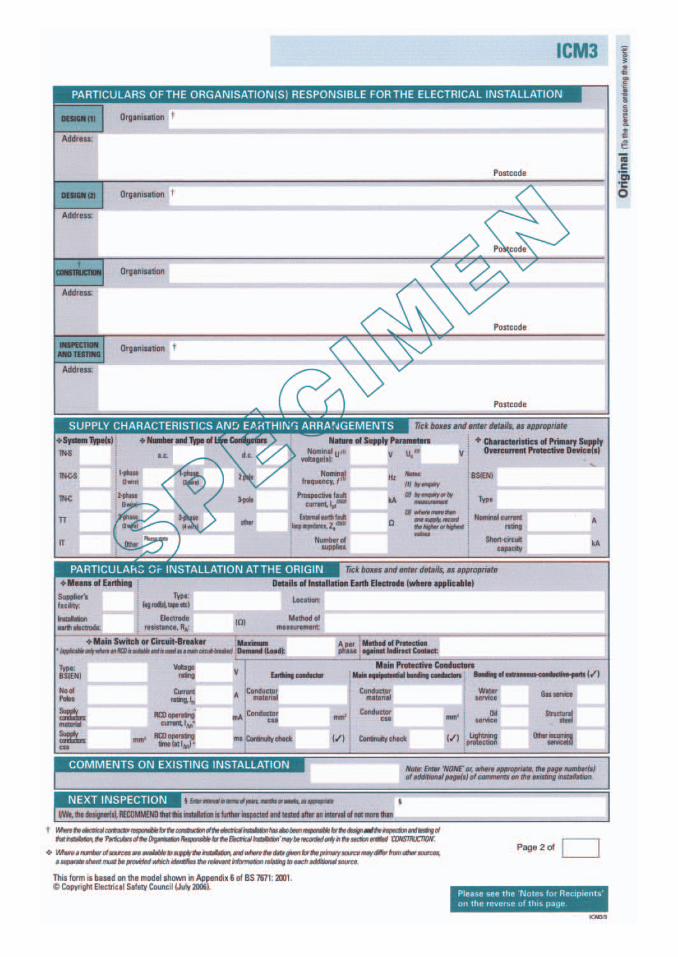
Supply characteristics
Type of system Is it TT, TNS or TNCS?
Number and type of live conductors Usually 1 phase 2 wire or 3 phase 4 wires(only live conductors).
Nature of supply parameters This can be gained by enquiry or measurement.
U. Is phase to phase or phaseUo Is phase to earth
Do not record measured values. If 3 phase or 3 phase and neutral, then the valuewill be U. 400 V and Uo 230 V. If single phase, then U and Uo will be 230 V.
External earth loop impedance (Ze) It should be measured between the phaseand earth on the live side of the main switch with the earthing conductordisconnected (remember to isolate the installation first). If measurement isnot possible, then it can be obtained by asking the supply provider.
Overcurrent protective device for the supply Usually this will be a BS 88 orBS 1361 cartridge fuse and it will normally be marked on the supply cutout. If it is not, then it should be found by asking the supply provider.
It is important that the BS or BS EN number, type, current rating and shortcircuit capacity is recorded (short circuit capacities can be found in Table 7.2A inthe On-Site Guide).
Particulars of installation at the origin
Means of earthing Is the earthing supplied by the distributor or has it got anearth electrode?
Details of earth electrode If the system has an earth electrode, what type is it?Where is it? What is its resistance? (This is usually measured with an earth loopimpedance tester, using the same method as for Ze.)
Maximum demand What is the load per phase? This value is not the rating ofthe supply fuse or the addition of the circuit protective device ratings. Itmust be assessed using diversity. The use of Table 1B in Appendix 1 of theOn-Site Guide can be helpful. However, the use of common sense andexperience is probably the best way to deal with this.
Electrical Installation Certificate
119
Earthing conductor Conductor material, what material is the earthingconductor made of? It must be copper if less than 16 mm2.
Conductor CSA Size of the conductor (in mm2).
Continuity This must be measured end to end or, if it is visible for its entirelength, a visual check is OK.
Main equipotential bonding conductors What are they made of and what hasbeen bonded?
Main switch or circuit breaker What type of switch is it – BS, BS EN or IEC?
Voltage and current rating Whatever is marked on it.
Number of poles Single pole, double pole, triple pole or triple pole andneutral.
Supply conductors Size of tails (in mm2).
If an RCD is fitted as a main switch, the operating current IΔn and theoperating time at IΔn must be recorded.
Comments on the existing installation If the certificate covers the wholeinstallation then usually ‘none’ will be entered here. If the installation isold, or you have any concerns, you may enter here that a PeriodicInspection Report would be advisable. Perhaps there are socket outletswhich could be used for the supply of portable equipment used outside. Inthis instance, a recommendation that an RCD is fitted may be entered.
Wiring regulations are not retrospective, so it is not a requirement when wiringthat complied when it was first installed is then updated. As you may be the firstperson to have looked at the installation for many years, your professional adviceshould be important to your client, and it may be an excellent sales opportunity.It is important to remember that if you are completing an Electrical InstallationCertificate, then the earthing and bonding arrangements must be improved tocomply with the requirements set out by BS 7671.
Completion of Test Certificates
120
Schedule of Circuit Details and Test Results
The Schedule of Test Results and the Schedule of Circuit Details are the basicdocuments. Some certification bodies have certificates which are a little morecomprehensive. Details of how to complete them can be found in the Surveyand Test Results Schedule – it is important that when completing thisdocument that each box in the row being completed is marked (this can bethe value, a tick, ‘n/a’ or ‘/’).
Completion of Test Certificates
121
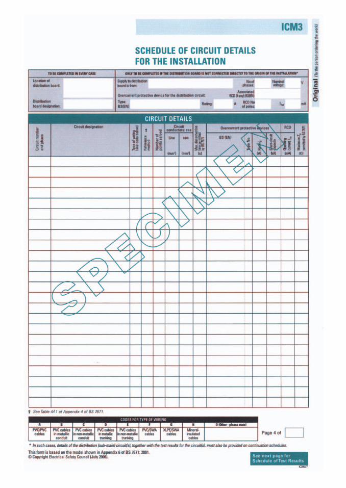
Location of distribution board Where is it?
Designation of consumer unit If there is more than one unit how is itidentified – number, name or letter?
Circuit designation What does the circuit supply? Is it a cooker, ring, etc?
If the circuit is fed by a submain (distribution circuit), details of the sub-mainmust be recorded. Possibly on a separate schedule, or on the top line of theschedule which you are completing.
Type of wiring Is it PVC twin and CPC, plastic or steel conduit? Somecertification bodies have their own codes for this.
Reference method How is it installed? The methods are detailed in Appendix4 of BS 7671.
Number of points served How many outlets or items of fixed equipment areon the circuit?
Circuit conductor size What size are live conductors and CPC? (give in mm2).
Maximum disconnection time permissible for the circuit Normally 0.4seconds for circuits supplying hand held equipment; 5 seconds for fixedequipment. Some special locations will have other requirements.
Type of over-current protective device
BS or BS EN. Enter the number.
Type If BS 1361 it will be a number 1, 2, 3 or 4; if BS EN it will be B, C, or D.The letter A was not used in case it was mistaken for Amperes. If the deviceis a fuse ‘/’ should be entered.
Rating What is the current rating of the device?
Short circuit capacity What is the short circuit capacity of the device? It maybe marked on the device; if it is not, then Table 7.2A in the On-Site Guidewill be of assistance.
Whatever it is, it must be at least equal to the PFC measured at the mainswitch of the consumer unit.
Maximum ZS
This is the maximum ZS permitted by BS 7671 for the protective device in thiscircuit. This value can be found in Tables 41B1, 41B2 or 41D in the On-SiteGuide. Be careful to use the correct table relating to the disconnection timefor the circuit if fuses are used. Do not use Table 41C here.
Schedule of Circuit Details for the Installation
123
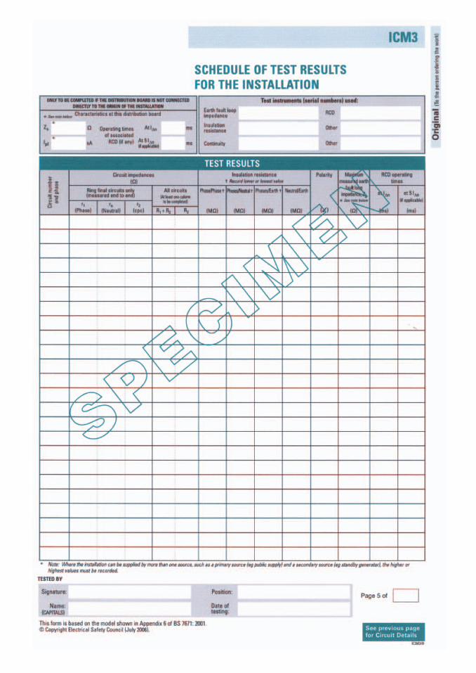
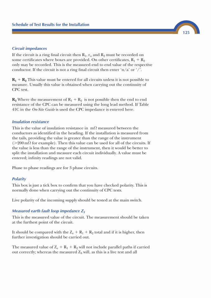
Circuit impedances
If the circuit is a ring final circuit then R1, rn and R2 must be recorded onsome certificates where boxes are provided. On other certificates, R1 � R2only may be recorded. This is the measured end to end value of the respectiveconductor. If the circuit is not a ring final circuit then enter ‘n/a’ or ‘/’.
R1 � R2 This value must be entered for all circuits unless it is not possible tomeasure. Usually this value is obtained when carrying out the continuity ofCPC test.
R2 Where the measurement of R1 � R2 is not possible then the end to endresistance of the CPC can be measured using the long lead method. If Table41C in the On-Site Guide is used the CPC impedance is entered here.
Insulation resistance
This is the value of insulation resistance in mΩ measured between theconductors as identified in the heading. If the installation is measured fromthe tails, providing the value is greater than the range of the instrument(�200 mΩ for example). Then this value can be used for all of the circuits. Ifthe value is less than the range of the instrument, then it would be better tosplit the installation and measure each circuit individually. A value must beentered; infinity readings are not valid.
Phase to phase readings are for 3 phase circuits.
Polarity
This box is just a tick box to confirm that you have checked polarity. This isnormally done when carrying out the continuity of CPC tests.
Live polarity of the incoming supply should be tested at the main switch.
Measured earth fault loop impedance ZS
This is the measured value of the circuit. The measurement should be takenat the furthest point of the circuit.
It should be compared with the Ze � R1 � R2 total and if it is higher, thenfurther investigation should be carried out.
The measured value of Ze � R1 � R2 will not include parallel paths if carriedout correctly; whereas the measured ZS will, as this is a live test and all
Schedule of Test Results for the Installation
125
protective conductors must be connected for the test to be carried out safely.Therefore, the measured ZS should be the same as the Ze � R1 � R2 value oreven less if parallel paths are present. It should not be higher!
RCD operating times
At IΔn: the actual operating time at the trip rating should be enteredhere.
At 5 IΔn: this value is only applicable for RCDs used for supplementaryprotection against direct contact. It should not be measured on any devicewith an IΔn above 30 mA.
Other
Under the heading of RCD operating times, there is often a column labelled‘other’. This is where the correct mechanical operation of switches, circuitbreakers and isolators, etc. are recorded.
Remarks
This area is for the inspector to record anything about the circuit thathe/she feels necessary. It may not be a fault but possibly something that maybe useful to the next person carrying out an inspection and test on theinstallation.
Completion of Test Certificates
126
Schedule of Items Inspected
This certificate, along with the Schedule of Test Results, forms part of theElectrical Installation Certificate and the Periodic Test Report. Without theseschedules the other certificates and reports are invalid.
Completion of this certificate involves the completion of boxes which must bemarked using a ‘✓’, ‘X’ or ‘n/a’ after the inspection is made, and could beuseful as a checklist.
Completion of Test Certificates
127
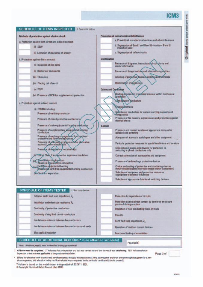
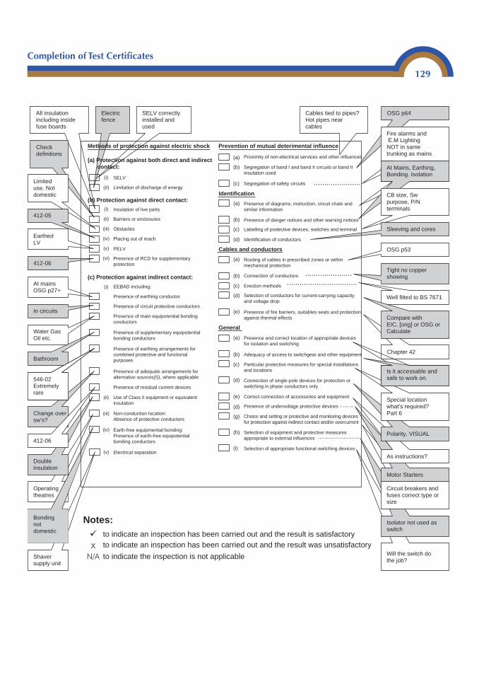
Completion of Test Certificates
129
Shaver supply unit
Check definitions
Will the switch do the job?
Isolator not used as switch
Circuit breakers and fuses correct type or size
Motor Starters
As instructions?
Polarity, VISUAL
Special location what’s required? Part 6
Chapter 42
Well fitted to BS 7671
Operating theatres
Limited use. Not domestic
All insulation including inside fuse boards
412-05
412-06
Earthed LV
At mains OSG p27+
In circuits
Water Gas Oil etc.
Bathroom
Double insulation
Change over sw’s?
Cables tied to pipes? Hot pipes near cables
OSG p64
Fire alarms and E.M Lighting NOT in same trunking as mains
At Mains, Earthing, Bonding. Isolation
CB size, Sw purpose, P/N terminals
Sleeving and cores
Tight no copper showing
OSG p53
Compare with EIC, [orig] or OSG or Calculate
Is it accessable and safe to work on.
Electric fence
SELV correctly installed and used
Methods of protection against electric shock Prevention of mutual deterimental influence
(a) Protection against both direct and indirect contact:
(i)
(iI)
SELV
Limitation of discharge of energy
Insulation of live parts
Barriers or enclosures
Obstacles
Placing out of reach
PELV
Presence of RCD for supplementary protection
EEBAD including:
Presence of earthing conductor
Presence of circuit protective conductors
Presence of main equipotential bonding conductors
Presence of supplementary equipotential bonding conductors
Presence of earthing arrangements for combined protective and functional purposes
Presence of adequate arrangements for alternative sources(S), where applicable
Presence of residual current devices
Use of Class II equipment or equivalent insulation
Non-conduction location: Absence of protective conductors
Earth-free equipmential bonding: Presence of earth-free equipotential bonding conductors
Electrical separation(v)
(iv)
(iii)
(ii)
(i)
(vi)
(v)
(iv)
(iii)
(ii)
(i)
(b) Protection against direct contact:
(a)
(b)
(b)
(b)
(b)
(c)
(c)
(c)
(c)
(d)
(d)
(d)
(e)
(e)
(d)
(g)
(h)
(i)
(a)
(a)
(a)
Proximity of non-electrical services and other influences
Segregation of band I and band II circuits or band II insulation used
Segregation of safety circuits
Presence of diagrams, instruction, circuit chats and similar information
Presence of danger notices and other warning notices
Labelling of protective devices, switches and terminal
Identification of conductors
Routing of cables in prescribed zones or within mechanical protection
Connection of conductors
Erection methods
Selection of conductors for current-carrying capacityand voltage drop
Presence of fire barriers, suitables seals and protection against thermal effects
Presence and correct location of appropriate devicesfor isolation and switching
Adequacy of access to switchgear and other equipment
Particular protective measures for special installations and locations
Connection of single-pole devices for protection or switching in phase conductors only
Correct connection of accessories and equipment
Presence of undervoltage protective devices
Choice and setting or protective and monitoring devices for protection against indirect contact and/or overcurrent
Selection of equipment and protective measures appropriate to external influences
Selection of appropriate functional switching devices
Bonding not domestic
Notes:to indicate an inspection has been carried out and the result is satisfactoryto indicate an inspection has been carried out and the result was unsatisfactory
to indicate the inspection is not applicable
.......................................................
......................Identification
Cables and conductors
General
(c) Protection against indirect contact:
...........................
.........
�
xN/A
546-02 Extremely rare
412-06
Method of protection against electric shock
Protection against both direct and indirect contact
SELVIf used for protection against direct contact it must not exceed 25 V a.c. or60 V d.c (Regulations 411-02-01, 412-02-09). Special locations require 12 V a.c.and 30 V d.c.
In domestic installations it is most commonly found supplying extra low voltagelighting, door bells, door entry systems, warden call and security systems.
Commonly found in commercial installations supplying shop window displaylighting where halogen luminaires are fed and supported by bare catenarywires.
Warden call and door entry systems should be excluded from the inspectionas a simple visual inspection will suffice.
Limitation of discharge of energyElectric fence controllers use this type of protection which is unlikely to beencountered in a domestic situation. They should be checked for completesegregation (Regulations 411-04-01, 471-03-01, 605-14).
Protection against direct contact
Insulation of live partsApplies to all electrical installations. This requires the inspection of all liveparts for insulation and should be carried out on a sampling basis(Regulations 412-02, 471-04).
Barriers or enclosuresApplies to all electrical installations. All enclosures should comply withRegulation 412-03-01/4; horizontal top surfaces to enclosures IP4X sides,front and bottom IP2X or IPXXB.
Blanks fitted to distribution boards. Access to live parts by use of a key or tool,secondary barriers within enclosures only removable with the use of a key or a tool.
ObstaclesThese can be used to prevent unintentional contact with bare live parts. Mustbe removable without the use of a key or tool but must be secured so as toprevent unintentional removal (Regulations 412-04, 471-06). Not used indomestic installations.
Schedule of Items Inspected
130

Schedule of Items Inspected
131
Placing out of reachApplies to overhead lines. Not likely to be found in domestic installations(Regulations 412-05, 471-07).
PELVExtra low voltage system, usually with an earthed secondary output. Oftenused to supply security systems and door entry systems. These systems shouldnot be used in communal systems as there is a risk of imported and exportedearth potentials (Regulations 471-14-01/2 restrict the use of PELV).
Presence of RCD for supplementary protection
Where socket outlets could be reasonably expected to supply handheld/portable equipment used outdoors, an RCD with a maximum operatingcurrent of 30 mA must be installed (Regulations 412-06-01/2, 471-16).
This method must not be used as the sole means of protection against directcontact.
Protection against indirect contact
Earthed Equipotential Bonding and automatic Disconnection of Supply(EEBADS, Regulation 413-01)
For TN systems, see Regulations 413-02-06/17. For TT systems, seeRegulations 413-02-18/20. This will include the following.
Presence of earthing conductorAn installation must have an earthing conductor which must be presentbefore any live testing can be carried out (Regulations 413-02-06, 413-02-18).
This relates to the supply earth which can be an earth electrode (Regulation542-01).
Presence of circuit protective conductorEach circuit must have a CPC which must be tested for continuity.
Presence of main equipotential bonding conductorRegulation 413-02-02. Extraneous parts of the installation must be connectedto the Main Earthing Terminal (MET) to comply with Section 547 regulations.
Presence of supplementary equipotential bondingRegulation 413-02-27. This is required to connect extraneous and exposedconductive parts in situations where there is a greater risk of electric shock.
In a domestic installation the supplementary bonding of bathrooms is arequirement (Regulations 601-04-01/2). This does not exclude the bondingof other areas where a risk is present.
Presence of earthing arrangements for combined and functional purposesRegulation 607 may apply. Generally for data equipment with protectiveconductor currents. This current is filtered via capacitors through afunctional earth. Equipment metalwork would become live if the earth waslost. This does not apply to domestic installations.
Presence of adequate arrangements for alternative sources where applicableNormally for generating sets and alternative sources of energy. These sourcesshould be checked to ensure compliance with Regulations 551, 331 and 56.Not normally applicable to domestic installations.
Presence of residual current deviceRegulations 413-02-19/20 for TT systems and 413-02-04, 16/17 for TNsystems. Also used for fire protection (Regulations 482-02-06 and 605-10-01).Test for correct operation.
Use of Class II equipment or equivalent insulationRegulations 413-03 and 471-09-03. Double insulated equipment used. Notoften found in fixed wiring although possibly found on bell transformers andcall systems. Look for markings.
Non-conducting locationsUsed in special areas in hospitals and laboratories. Requires specialistknowledge (Regulation 413-04).
Earth free equipotential bondingRegulation 413-05. Found in electronic repair workshops, specialistknowledge required.
Electrical separationRegulation 413-06. Used in bathrooms for shaver sockets. The secondarysupply is isolated from earth. Does not include SELV.
Prevention of mutual detrimental influence
Proximity of non electrical services and other influencesRegulations 528-02-01/2 and Section 522. Items should be inspected toensure the electrical system cannot cause harm to non electrical services, and
Schedule of Items Inspected
132
that the electrical system is unaffected by external influences. Cables tied topipes or next to central heating pipes for example.
Segregation of band 1 and band II circuits or band II insulation usedRegulations 470-01-02 , 515-01-02, 522-05-03 and Section 528-2/3. Low voltagecables not in same enclosures as extra low voltage cables, such as TV aerials,door bells and telephone cables.
Segregation of safety circuitsRegulations 528-01-04, 563-01-01. Fire alarm and emergency lighting to besegregated from each other and other circuits unless wired in cables with anearthed metal sheath with an insulated covering. This could be Mineralinsulated, Firetuff and FP200.
Identification
Presence of diagrams, instructions, circuit charts and similar informationRegulations 514-09-01. Circuit charts, plans, past inspection and testcertificates and schedules must be available. For domestic installations, circuitidentification would be a minimum requirement on an older installation.
Presence of danger notices and other warning noticesRegulations 541-10-01, 54-11-01, 541-12-01/02, 541-13-01/02. Earth bondinglabels, voltage warnings, isolation, harmonization of colours and RCD testingare common.
Labelling of protective devices, switches and terminalsRegulations 514-01-01/2, 514-08-01. Protective devices labelled, conductors insequence. Switches and isolators marked to identify the item they control ifnot obvious.
Identification of conductorsRegulations 514-03-01, 514-06-01/2/3/4, 514-07-01/2. Coloured sleeve onswitch wires or where phase conductors are not clearly identified.
Cables and conductors
Routing of cables and in prescribed zones or within mechanical protectionRegulations 522-06-01 to 7 or 7.3.1/7.3.2, On-Site Guide. Intended for usewhen completing an Electrical Installation Certificate. Only limited inspectionwould be possible during a Periodic Inspection Report.
Schedule of Items Inspected
133
Connection of conductorsRegulations 526-01-01, 526-04-01. Check for tightness and correct use ofterminations at a random selection of accessories and all distribution boards.
Erection methodsRegulation Table 4A, Appendix 4 and 522. Correct type of installation to suitenvironment, standard of workmanship and suitability of fixings.
Selection of conductors for current carrying capacity and voltage dropRegulation 314-01-03, Chapter 43 and 525, and tabulated values in Appendix 4.Cables to be checked for correct selection with due regard to length, groupingand temperature. Experience is useful here unless design information isavailable, as generally it would be impractical to carry out volt drop measure-ments on fully loaded circuits, although this can be calculated using R1 � R2.
Presence of fire barriers, suitable seals and protection against thermal effectsRegulations, Chapter 42 and Section 527. This is to ensure structural firebarriers are not broken during installation, fire barriers in trunking andducting where required and intumescent hoods on lighting where installed infire rated ceilings. Heat from installed equipment is not likely to cause a fire. In particular, check that backless accessories such as wall lights and electricalenclosures installed on surfaces are suitable for surface temperatures andradiated heat of equipment.
General
Presence and correct location of appropriate devices for isolation and switchingRegulations 476, 514-01-01, 537, Chapter 46. Isolators identified where notobvious, local and under the control of the user or, if remote, they must belockable and identified. Isolation for fans with time control in bathrooms.
Adequacy of access to switchgear and other equipmentRegulations 513-01-01, 526-04-01, 537-04-04, 543-03-03. Doors of enclosuresmust be removable or able to be fully opened. Access to equipment shouldnot be obstructed. Cooker control switches within 2 metres of cooker and hob(Appendix 8, On-Site Guide).
Particular protective measures for special installations and locationsRegulation, Part 6. Bathrooms most common in domestic environment.
Schedule of Items Inspected
134
Connection of single pole devices for protection and switching in phaseconductors onlyRegulations 530-01-01/2. Switches in phase and not neutral conductors,generally carried out when continuity of CPC tested along with a visual check.
Correct connection of accessories and equipmentRegulation 712-01-03 and Chapter 526. Check for correct and neatconnection, look for excessive exposed conductors, cores of cables not cut outwhere terminal full.
Presence of undervoltage protective devicesChapter 45. Motor starters and contactors fitted with correct coils whichdisconnect on undervoltage and unable to automatically make contacts whencorrect supply resumed unless physically operated.
Choice and setting of protective and monitoring devices for protection againstindirect contact and/or overcurrentCorrect size and type of protective devices/RCD are suitable for use to whichthey are being put. Monitoring devices not found in domestic situations oftenfound on IT supply systems and some construction sites.
Selection of equipment and protective measures appropriate to external influencesRegulations 512-06-01, 542-01-07, Appendix 5, Chapter 52. Check forsuitability of wiring system for the environment and type of use to which it isbeing put.
Selection of appropriate functional switching devicesRegulations 464 and 537-05. Correct operation of switches/isolatorsthroughout installation.
Schedule of Items Inspected
135
Periodic Inspection Report for an Electrical Installation
136
Periodic Inspection Report
This document is used to record the condition of an installation. In particular, is it safe to use? At the time of writing, it is not a requirement for the person completing this report to be Part P compliant. It is, however,important that the person carrying out the inspection and test is competent.
The report must also include a Schedule of Test Results and a Schedule ofInspection.
A periodic inspection report is carried out for many reasons, in particular:
The due dateClient’s/customer’s requestChange of ownershipChange of useInsurance purposesTo inspect the condition of the existing installation, prior to carrying out
any alterations or additions
The frequency of the periodic inspection and test is dependent on the type ofinstallation, the environment and the type of use. BS 7671 Wiring Regulationsrefer to this as the ‘Construction, utilization and environment’ and this can befound in Appendix 5 of BS 7671.
Guidance note 3 for the inspecting and testing of electrical installationshas a table of recommended frequencies for carrying out periodic inspectionand tests – the period depends on the type of installation. However, therecommended frequencies are not cast in stone and it is the responsibility ofthe person carrying out the periodic inspection and test to decide on theperiod between tests.
This decision should be based on the inspector’s experience, what theinstallation is used for, how often it is used, and the type of environment thatsurrounds the installation. These things and many others should be takeninto account when setting the next test date.
It is important to remember that the date of the first inspection and test is setby the person responsible for the installation design. However, circumstanceschange which could affect the installation – such as change of use orownership.
Periodic Inspection Report for an Electrical Installation
137
Careful consideration must be given to the installation before the date of thenext periodic inspection and test is set.
It is very important that the extent and limitations of the inspection andtest is agreed with the person ordering the work before commencing work.
Before the extent and limitation can be agreed, discussion between all partiesinvolved must take place. The client will know why they want the inspectioncarried out and the person who is carrying out the inspection and testshould have the technical knowledge and experience to give the correctguidance.
Past test results, electrical installation, or periodic inspection reports, fusecharts, etc. must be made available to the person carrying out the inspectionand test.
If these are not available, then a survey of the installation must be carried outto ensure that the installation is safe to test and to prepare the requiredpaperwork, such as fuse charts.
Whilst carrying out a periodic inspection and test it is not a requirement totake the installation apart. This should be carried out with the minimum ofintrusion; disconnection should only be carried out when it is impossible tocarry out the required test in any other way. For example, if an insulationresistance test is required on a lighting circuit with fluorescent lightingconnected to it.
The simple method would be to open the switch supplying the fluorescentfitting before testing between the live conductors, and close the switch whenconducting the test between live conductors and earth. It is not a requirementto disconnect the fitting (see insulation resistance testing, Chapter 4).
Completing the form
As with a Minor Works or an Electrical Installation Certificate, theinformation required on a Periodic Inspection and Test Report will varydepending on where the report is obtained from.
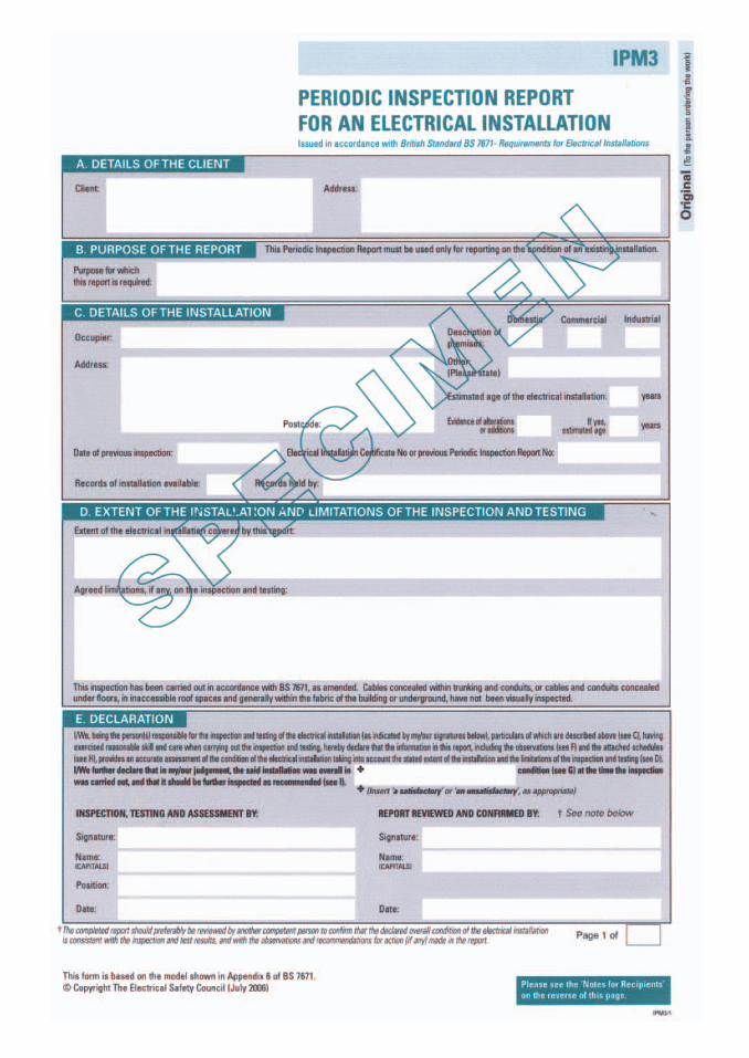
Details of the client Name and address of the person ordering the work.
Installation address Where is the installation?
Details of the installation Age: Often this has to be an estimate based on anyevidence and the inspector’s experience. Alterations: Have any alterationsbeen carried out since the last inspection and test? If so how long ago? Arerecords available? Who are they kept by?
Purpose of the report Why are you carrying out the inspection and test?
Extent and limitation How much of the installation are you going to inspect?How much are you going to test? Are there any rooms which you cannotgain access to, or circuits which must not or cannot be isolated? Generally,a minimum of 10% of each circuit must be inspected. The extent of theinspection could be increased if problems/unsafe situations arediscovered.
Periodic Inspection Report for an Electrical Installation
139
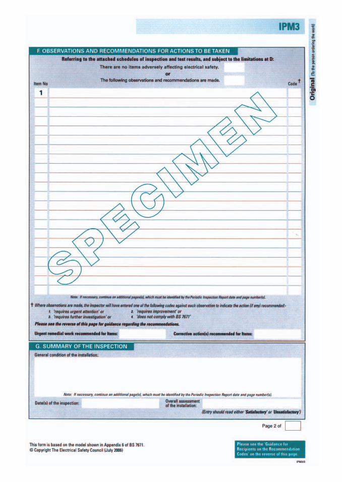
Observations and recommendations
Defects, if any, must be recorded accurately here and a code given to them. Somecertificates have codes to indicate the level of attention required. On most certificatesthe codes will be:1. Requires urgent attention Anything which could compromise the safety of those
using the installation should be entered here. This would include lack of earthing,undersized cables, damaged accessories, high Zs values. It is up to the personcarrying out the inspection to make a judgement on this.
2. Requires improvement Defects which do not immediately cause the installation tobe regarded as unsafe but which could be problematic in the future. This couldbe: corrosion; old cables such as lighting cables with no CPC terminated inwooden switch boxes; labels missing, etc. Again a judgement must be made by theperson carrying out the inspection.
3. Requires further investigation This could be anything that the person who is carryingout the inspection and test is concerned about, but which is outside of the agreedextent of the inspection. Possibly a circuit which cannot be traced, or instrumentvalues within the required parameters – anything that might cause concern.
4. Does not comply with BS 7671 As the requirements of BS 7671 are amended, partsof the installation which would have complied when the installation was new, maynow not comply. Examples of this could be: socket outlets that could be used tosupply portable equipment outdoors, not protected by an RCD, CPCs which havebeen sleeved with green sleeving and not green and yellow. Switch returns notidentified on older installations.
It must be remembered that it is the responsibility of the person carrying out theinspection to decide on which code to give, the decision should be made using theinspector’s experience and common sense.
A true and accurate reflection of the installation must be recorded here. It may requireadditional pages to explain in detail any observations and recommendations. Do not beinfluenced by cost or the difficulty in rectifying any defects. The person signing thecertificate will be responsible for its content.
Summary of the inspection
This section of the certificate is to detail the overall condition of the installation. It isoften easier for the inspector to break the installation into specific areas, for instance:
Any change of use or environment which may have had an affect on the installationEarthing arrangementsBondingIsolationAgeSafety
Overall assessment
This will either be satisfactory or unsatisfactory. In general terms, if the observation areaof the form has any defects other than code 4, the assessment must be unsatisfactory.
Periodic Inspection Report for an Electrical Installation
141
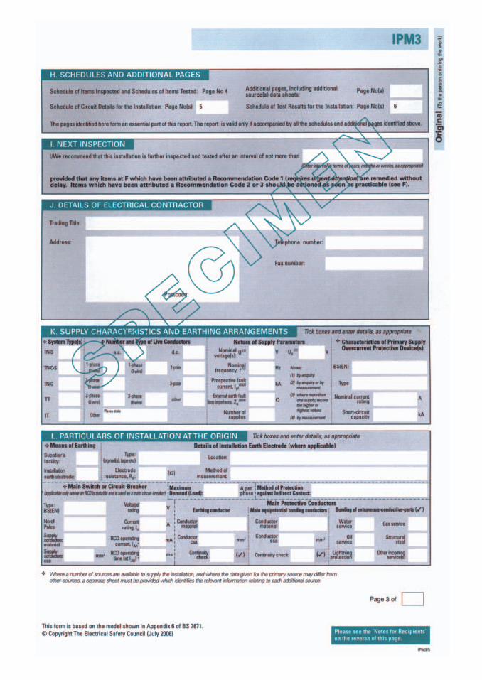
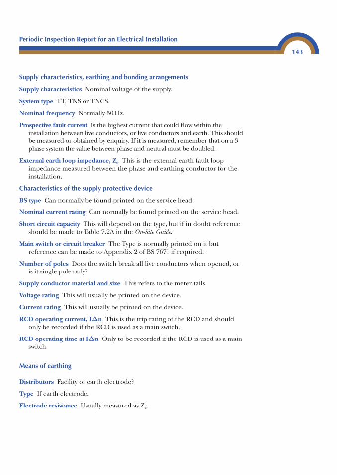
Supply characteristics, earthing and bonding arrangements
Supply characteristics Nominal voltage of the supply.
System type TT, TNS or TNCS.
Nominal frequency Normally 50 Hz.
Prospective fault current Is the highest current that could flow within theinstallation between live conductors, or live conductors and earth. This shouldbe measured or obtained by enquiry. If it is measured, remember that on a 3phase system the value between phase and neutral must be doubled.
External earth loop impedance, Ze This is the external earth fault loopimpedance measured between the phase and earthing conductor for theinstallation.
Characteristics of the supply protective device
BS type Can normally be found printed on the service head.
Nominal current rating Can normally be found printed on the service head.
Short circuit capacity This will depend on the type, but if in doubt referenceshould be made to Table 7.2A in the On-Site Guide.
Main switch or circuit breaker The Type is normally printed on it butreference can be made to Appendix 2 of BS 7671 if required.
Number of poles Does the switch break all live conductors when opened, oris it single pole only?
Supply conductor material and size This refers to the meter tails.
Voltage rating This will usually be printed on the device.
Current rating This will usually be printed on the device.
RCD operating current, IΔn This is the trip rating of the RCD and shouldonly be recorded if the RCD is used as a main switch.
RCD operating time at IΔn Only to be recorded if the RCD is used as a mainswitch.
Means of earthing
Distributors Facility or earth electrode?
Type If earth electrode.
Electrode resistance Usually measured as Ze.
Periodic Inspection Report for an Electrical Installation
143
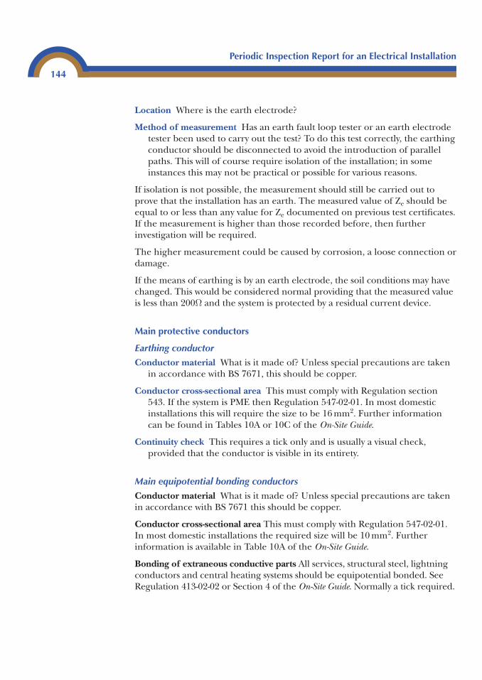
Location Where is the earth electrode?
Method of measurement Has an earth fault loop tester or an earth electrodetester been used to carry out the test? To do this test correctly, the earthingconductor should be disconnected to avoid the introduction of parallelpaths. This will of course require isolation of the installation; in someinstances this may not be practical or possible for various reasons.
If isolation is not possible, the measurement should still be carried out toprove that the installation has an earth. The measured value of Ze should beequal to or less than any value for Ze documented on previous test certificates.If the measurement is higher than those recorded before, then furtherinvestigation will be required.
The higher measurement could be caused by corrosion, a loose connection ordamage.
If the means of earthing is by an earth electrode, the soil conditions may havechanged. This would be considered normal providing that the measured valueis less than 200Ω and the system is protected by a residual current device.
Main protective conductors
Earthing conductor
Conductor material What is it made of? Unless special precautions are takenin accordance with BS 7671, this should be copper.
Conductor cross-sectional area This must comply with Regulation section543. If the system is PME then Regulation 547-02-01. In most domesticinstallations this will require the size to be 16 mm2. Further informationcan be found in Tables 10A or 10C of the On-Site Guide.
Continuity check This requires a tick only and is usually a visual check,provided that the conductor is visible in its entirety.
Main equipotential bonding conductors
Conductor material What is it made of? Unless special precautions are takenin accordance with BS 7671 this should be copper.
Conductor cross-sectional area This must comply with Regulation 547-02-01.In most domestic installations the required size will be 10 mm2. Furtherinformation is available in Table 10A of the On-Site Guide.
Bonding of extraneous conductive parts All services, structural steel, lightningconductors and central heating systems should be equipotential bonded. SeeRegulation 413-02-02 or Section 4 of the On-Site Guide. Normally a tick required.
Periodic Inspection Report for an Electrical Installation
144
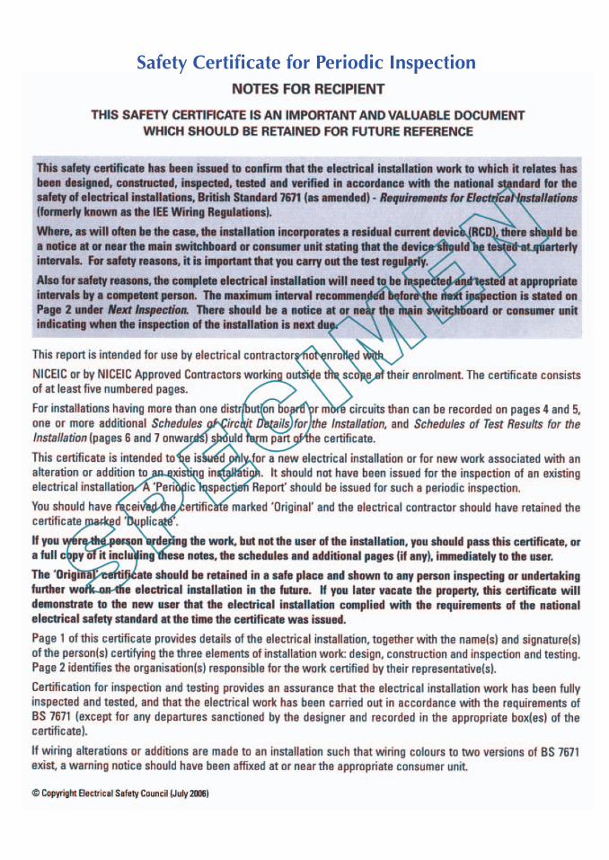
Safety Certificate for Periodic Inspection
Safety Certificate for Electrical Installation
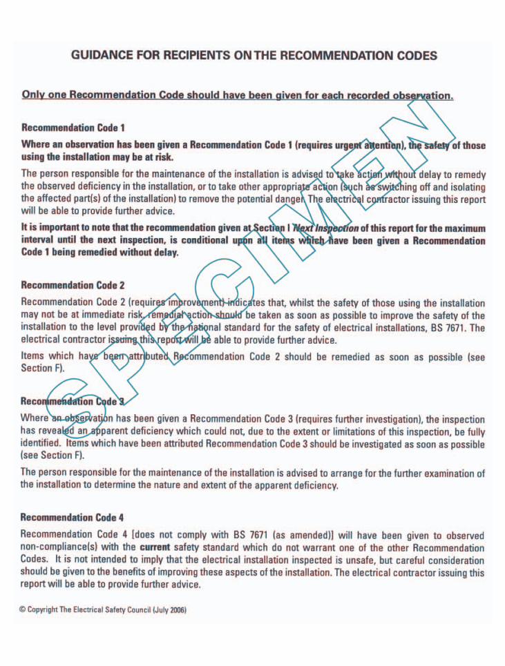
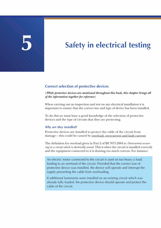
Safety in electrical testing3
Correct selection of protective devices
(While protective devices are mentioned throughout this book, this chapter brings allof the information together for reference)
When carrying out an inspection and test on any electrical installation it isimportant to ensure that the correct size and type of device has been installed.
To do this we must have a good knowledge of the selection of protectivedevices and the type of circuits that they are protecting.
Why are they installed?
Protective devices are installed to protect the cable of the circuit fromdamage – this could be caused by overload, overcurrent and fault current.
The definition for overload given in Part 2 of BS 7671:2004 is: Overcurrent occurr-ing in a circuit which is electrically sound. This is when the circuit is installed correctlyand the equipment connected to it is drawing too much current. For instance:
5
An electric motor connected to the circuit is used on too heavy a load,leading to an overload of the circuit. Provided that the correct size ofprotective device was installed, the device will operate and interrupt thesupply preventing the cable from overloading.
If additional luminaries were installed on an existing circuit which wasalready fully loaded, the protective device should operate and protect thecable of the circuit.
Overcurrent is a current flow in a circuit which is greater than the ratedcurrent carrying capacity of the cables. This would normally be due to a faulton the circuit or incorrect cable selection. For example:
Safety in Electrical Testing
150
If a 20 amp cable protected by a 32 amp circuit breaker was loaded by 25 A, the cable would overheat and the device would continue to allowcurrent to flow – this could damage the cable.
A nail is driven through a cable causing an earth fault or a short circuit fault.This would cause a very high current to flow through the circuit, whichmust be interrupted before the conductors reach a temperature that coulddamage the insulation or even the conductors.
A fault current is a current which is flowing in a circuit due to a fault. Forexample:
So what are we looking for with regard to protective devices during aninspection?
What type of device is it? Is it a fuse or circuit breaker?
A fuse has an element which melts when too much current is passed throughit, whether by overload or fault current.
Fuses in common use are:
BS 3036 semi-rewirable fuseBS 88 cartridge fuseBS 1361 cartridge fuse
A circuit breaker is really two devices in one unit. The overload part of thedevice is a thermal bi metal strip, which heats up when a current of a highervalue than the nominal current rating (In) of the device passes through it.
Also incorporated within the device is a magnetic trip, which operates andcauses the device to trip when a fault current flows through it. For the deviceto operate correctly it must operate within 0.1 seconds. The current which hasto flow to operate the device in the required time has the symbol (Ia).
Circuit breakers in common use are:
☞☞ BS 3871 types 1, 2 and 3☞☞ BS EN types B, C and D (A is not used, this is to avoid confusion with Amps)
Is the device being used for protection against indirect contact?
In most instances this will be the case.
What type of circuit is the device protecting, is it supplying fixed equipmentonly, or could it supply handheld equipment?
If the circuit supplies fixed equipment only, the device must operate on faultcurrent within 5 seconds. If it supplies socket outlets it must operate within0.4 seconds (see BS 7671, Regulations 413-02-08 and 413-02-09).
When using circuit breakers to BS 3871 and BS EN 60898 these times can bedisregarded. Providing the correct ZS values are met, they will operate in 0.1 seconds or less.
If it is a circuit breaker is it the correct type?
Table 7.2b of the On-Site Guide provides a good reference for this.
Types 1 and B should be used on circuits having only resistive loads (have youever plugged in your 110 v site transformer and found that it operated the circuitbreaker? If you have it will be because it was a type 1 or B).
Types 2, C and 3 should be used for inductive loads such as fluorescentlighting, small electric motors and other circuits, where surges could occur.
Types 4 and D should be used on circuits supplying large transformers or anycircuits where high inrush currents could occur.
Will the device be able to safely interrupt the prospective fault current which could flow in the event of a fault?
Table 7.2A or the manufacturer’s literature will provide information on therated short circuit capacity of protective devices.
Is the device correctly coordinated with the load and the cable?
Correct coordination is:
Current carrying capacity of the cable under its installed conditions must beequal to or greater than the rated current of the protective device (Iz).
Safety in Electrical Testing
151
The rated current carrying capacity of the protective device (In) must beequal to or greater than the design current of the load (Ib).
In short, Iz � In � Ib (Appendix 4. item 4 BS 7671 or Appendix 6 On-Site Guide).
Additional information regarding circuit breakers
Overload currentThe symbol for the current required to cause a protective device to operatewithin the required time on overload is (I2).
Circuit breakers with nominal ratings up to 60 amps must operate within 1 hour at 1.45 � their nominal rating (In).
Circuit breakers with nominal ratings above 60 amps must operate within 2 hours at 1.45 � its rating (In).
At 2.55 times the nominal rating (In), circuit breakers up to 32 amps mustoperate within 1 minute; and circuit breakers above 32 amps, must operatewithin 2 minutes.
They must not trip within 1 hour at up to 1.13 their nominal rating (In).
Maximum earth fault loop impedance values (ZS) for circuit breakersThese values can be found in Table 41B2 in BS 7671, they can also be foundin Sections 604 and 605 of BS 7671.
Because these devices are required to operate within 0.1 of a second, they willsatisfy the requirements of BS 7671 with regard to disconnection times in allareas. Therefore, the ZS values for these devices are the same wherever theyare to be used (this only applies to circuit breakers) even in special locationswhere the disconnection time must be 0.2 seconds.
Calculation of the Maximum ZS of circuit breakersIt is often useful to be able to calculate the maximum ZS value for circuitbreakers without the use of tables. This is quite a simple process for BS 3871and BS EN 60898 devices. Let’s use a 20A BS EN 60898 device as an example:
Table 7.2b shows that a type B device must operate within a window of 3 to 5 times its rating. As electricians we always look at the worst case scenario.Therefore, we must assume that the device will not operate until a current
Safety in Electrical Testing
152
equal to 5 times its rating flows through it (Ia). For a 20 A type B device thiswill be 5 � 20 A � 100 A.
If we use a supply voltage of 240 volts – which is the assumed open circuitvoltage (UOC) of the supply (Appendix 3, BS 7671) – Ohm’s law can be usedto calculate the maximum ZS.
And to check this, we look in Table 41B2 of BS 7671, we will see that the valueZS for a 20 A type B device is 2.4 Ω.
Now let’s use the same procedure for a 20 A type C device. Table 7.2bshows us that a type C device must operate at a maximum of 10 times itsrating (In).
If we check again in Table 41B2, we will see that the maximum ZS for a 20 Atype C device is 1.2 Ω.
A type C circuit breaker with a nominal operating current (In) must operateat a maximum of 20 times its rating:
Again, if we check in Table 41B2 we will see that the ZS value is 0.6 Ω.
We can see that the maximum ZS values for a type C are 50% of the ZS value of a type B device, and that the ZS value for a type D are 50% of the ZS value of atype C device.
20 20 400
240
4000 6
� �
�
A
. Ω
10 20 200
240
2001 2
� �
�
A
. Ω
ZU
I
Z
SOC
a
S
�
� �240100
2 4. Ω
Safety in Electrical Testing
153
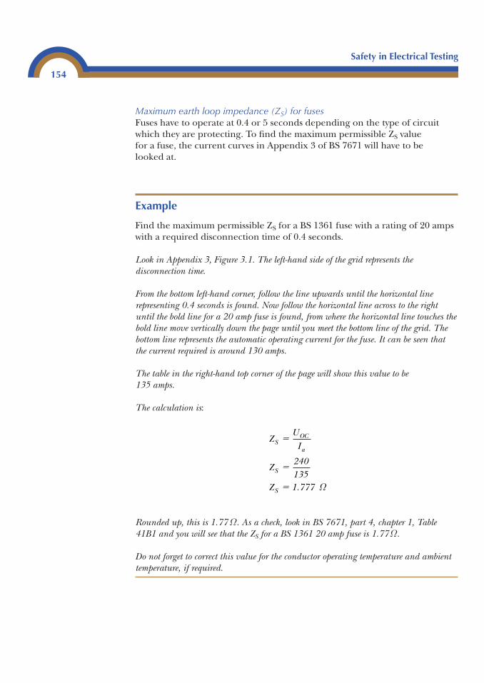
Maximum earth loop impedance (ZS) for fusesFuses have to operate at 0.4 or 5 seconds depending on the type of circuitwhich they are protecting. To find the maximum permissible ZS valuefor a fuse, the current curves in Appendix 3 of BS 7671 will have to belooked at.
Example
Find the maximum permissible ZS for a BS 1361 fuse with a rating of 20 ampswith a required disconnection time of 0.4 seconds.
Look in Appendix 3, Figure 3.1. The left-hand side of the grid represents thedisconnection time.
From the bottom left-hand corner, follow the line upwards until the horizontal linerepresenting 0.4 seconds is found. Now follow the horizontal line across to the rightuntil the bold line for a 20 amp fuse is found, from where the horizontal line touches thebold line move vertically down the page until you meet the bottom line of the grid. Thebottom line represents the automatic operating current for the fuse. It can be seen thatthe current required is around 130 amps.
The table in the right-hand top corner of the page will show this value to be135 amps.
The calculation is:
Rounded up, this is 1.77 Ω. As a check, look in BS 7671, part 4, chapter 1, Table41B1 and you will see that the ZS for a BS 1361 20 amp fuse is 1.77Ω.
Do not forget to correct this value for the conductor operating temperature and ambienttemperature, if required.
ZU
I
Z240135
Z 1.777
SOC
a
S
S
�
�
� Ω
Safety in Electrical Testing
154
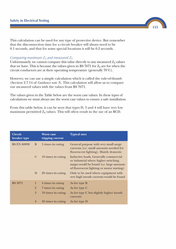
This calculation can be used for any type of protective device. But rememberthat the disconnection time for a circuit breaker will always need to be 0.1 seconds, and that for some special locations it will be 0.2 seconds.
Comparing maximum ZS and measured ZSUnfortunately, we cannot compare this value directly to any measured ZS valuesthat we have. This is because the values given in BS 7671 for ZS are for when thecircuit conductors are at their operating temperature (generally 70°C).
However, we can use a simple calculation which is called the rule-of-thumb(Section 2.7.14 of Guidance note 3). This calculation will allow us to compareour measured values with the values from BS 7671.
The values given in the Table below are the worst case values. In these types ofcalculations we must always use the worst case values to ensure a safe installation.
From this table below, it can be seen that types D, 3 and 4 will have very lowmaximum permitted ZS values. This will often result in the use of an RCD.
Safety in Electrical Testing
155
Circuit Worst case Typical usesbreaker type tripping current
BS EN 60898 B 5 times its rating General purpose with very small surgecurrents (i.e. small amounts needed forfluorescent lighting). Mainly domestic
C 10 times its rating Inductive loads. Generally commercialor industrial where higher switchingsurges would be found (i.e. large amountsof fluorescent lighting or motor starting)
D 20 times its rating Only to be used where equipment withvery high inrush currents would be found
BS 3871 1 4 times its rating As for type B
2 7 times its rating As for type C
3 10 times its rating As for type C but slightly higher inrushcurrents
4 50 times its rating As for type D
Example
Let’s assume that we have a circuit protected by a 32A BS EN 60898 type Bdevice. The measured value of ZS is 0.98 Ω.
Following the procedure described previously:
The maximum ZS at 70°C for the circuit is 1.5 Ω.
To find of 1.5 we can multiply it by 0.75.
1.5 � 0.75 � 1.125Ω
So, 1.125Ω now becomes our maximum value, and we can compare our measuredvalue directly to it without having to consider the ambient temperature or the conductoroperating temperature. Our measured value must be less than the corrected maximumvalue; in this case it is, and the 32 amp type B device would be safe to use.
Test equipment
It is important that the test equipment you choose is suitable for your needs.Some electricians prefer to use individual items of equipment for each test;others like to use multi-function instruments.
Any test instruments used for testing in areas such as petrol filling stations, orareas where there are banks of storage batteries, etc. In fact, anywhere there isa risk of explosion, must be intrinsically safe for the purpose.
Most electricians are aware that electrical test instruments must comply withBS standards. However, students studying for Part P and City and Guilds 2391exams, an understanding of the basic operational requirement for the mostcommon types of test instrument is very important.
Whichever instrument you choose it must be suitable for the use to which it isto be put and be manufactured to the required British standard. It is also vitalthat you fully understand how to operate it before you start testing.
34
5 32 160 A
1.5
� �
�240160
Ω
Safety in Electrical Testing
156
This type ofcalculation must beunderstood by anystudent studying forthe City and Guilds2391 inspecting andtesting course
Instruments required
Low resistance ohm meter
Used to measure the resistance and verify the continuity of conductors. Thisinstrument must produce a test voltage of between 4 and 24 volts and acurrent of not less than 200 mA. The range required is 0.02 to 2 ohmsalthough most modern instruments are self ranging and will measure highervalues if required.
Insulation resistance tester
Used to measure the insulation resistance between live conductors and liveconductors and earth. This test is a pressure test of conductor insulation.The instrument must deliver a current of 1 mA on a resistance of 0.5 MΩ.At 250 volts d.c. for extra low voltage circuits, 500 volts d.c. for low voltagecircuits up to 500 volts a.c. and 1000 volts d.c. for circuits between 500and 1000 volts d.c.
This instrument is sometimes called a high resistance tester as it measuresvalues in megohms.
Earth fault loop impedance tester
This instrument allows a current of up to 25 amps to flow around theearth fault loop path. It measures the current flow and by doing so cancalculate the resistance of the earth fault loop path. The values given arein ohms.
As a current of 25 amps will trip RCDs and some smaller circuit breakers, it is useful to have an instrument that can carry out low current testing whererequired. Use of this type of instrument will avoid the tripping of devicesduring testing.
Prospective short circuit current test instrument
This instrument measures the current that would flow between liveconductors in the event of a short circuit. It is usually incorporated in theearth loop impedance tester and normally gives a value in kA. Someinstruments give the value in ohms which then needs to be converted to amps by using Ohm’s law (use 240 volts).
Most instruments will measure the value between phase and neutral and notbetween phases; to find the value between phases it is simply a matter ofdoubling the phase to neutral value.
Safety in Electrical Testing
157
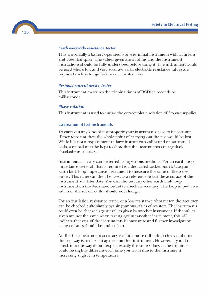
Earth electrode resistance tester
This is normally a battery operated 3 or 4 terminal instrument with a currentand potential spike. The values given are in ohms and the instrumentinstructions should be fully understood before using it. The instrument wouldbe used where low and very accurate earth electrode resistance values arerequired such as for generators or transformers.
Residual current device tester
This instrument measures the tripping times of RCDs in seconds ormilliseconds.
Phase rotation
This instrument is used to ensure the correct phase rotation of 3 phase supplies.
Calibration of test instruments
To carry out any kind of test properly your instruments have to be accurate.If they were not then the whole point of carrying out the test would be lost.While it is not a requirement to have instruments calibrated on an annualbasis, a record must be kept to show that the instruments are regularlychecked for accuracy.
Instrument accuracy can be tested using various methods. For an earth loopimpedance tester all that is required is a dedicated socket outlet. Use yourearth fault loop impedance instrument to measure the value of the socketoutlet. This value can then be used as a reference to test the accuracy of theinstrument at a later date. You can also test any other earth fault loopinstrument on the dedicated outlet to check its accuracy. The loop impedancevalues of the socket outlet should not change.
For an insulation resistance tester, or a low resistance ohm meter, the accuracycan be checked quite simply by using various values of resistors. The instrumentscould even be checked against values given by another instrument. If the valuesgiven are not the same when testing against another instrument, this willindicate that one of the instruments is inaccurate and further investigationusing resistors should be undertaken.
An RCD test instrument accuracy is a little more difficult to check and oftenthe best way is to check it against another instrument. However, if you docheck it in this way do not expect exactly the same values as the trip timecould be slightly different each time you test it due to the instrumentincreasing slightly in temperature.
Safety in Electrical Testing
158
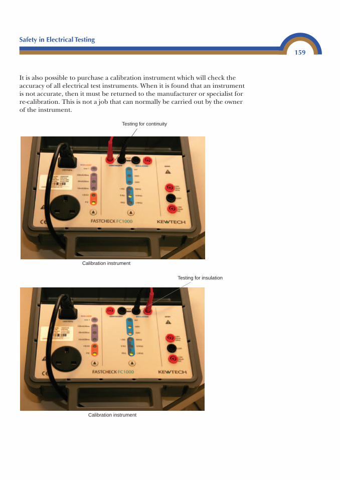
It is also possible to purchase a calibration instrument which will check theaccuracy of all electrical test instruments. When it is found that an instrumentis not accurate, then it must be returned to the manufacturer or specialist forre-calibration. This is not a job that can normally be carried out by the ownerof the instrument.
Safety in Electrical Testing
159
Testing for continuity
Calibration instrument
Testing for insulation
Calibration instrument
Recordkeeping for accuracy testing of the instrument is quite a simple butimportant process. A record showing the instrument model, serial numberand the date of the test along with the recorded values is all that is requiredand will satisfy most regulatory bodies. Records can be kept in a ledger, on acomputer. Alternatively, calibration registers can be purchased to make life alittle easier.
Electric shock
An electric shock is caused by current flowing through a body. A verysmall amount – between 50 and 80 mA is considered to be lethal to mosthuman beings, although this would of course depend on the person’shealth and other circumstances. In livestock the lethal current would beconsiderably less.
The electrical regulations are set out to provide for the safety of persons andlivestock. An electric shock is one risk of injury; others are:
• Excessive temperatures likely to cause burns, fire and other injuriouseffects.
• Mechanical movement of electrically actuated equipment, in so far as suchinjury is intended to be prevented by electrical emergency switching or byswitching for mechanical maintenance of non-electrical parts of suchequipment.
• Explosion.
This can be found in Chapter 13 of BS 7671 (Regulation 130-01-01).
Regulation 130-02-01 tells us that persons and livestock shall be protected sofar as is reasonably practical against dangers that may arise from contact withlive parts of the installation. This protection can be achieved by one of thefollowing methods.
For direct or indirect contact:
• Preventing current passing through the body of any person orlivestock.
• Limiting the current which can pass through a body to a value lower thanthe shock current.
Safety in Electrical Testing
160
If, for any reason,your instrumentdoes requirere-calibration, itshould be returnedto the instrumentmanufacturer or acalibration specialist.
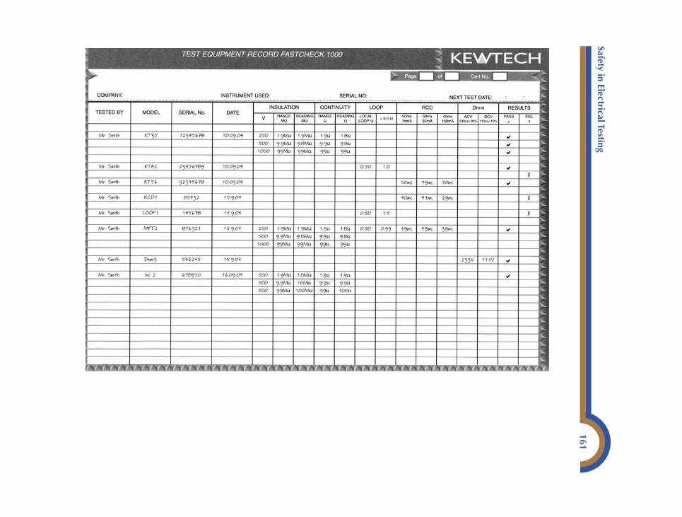
Safety in Electrical Testing
161
For indirect contact:
• Automatic disconnection of the supply in a determined time on theoccurrence of a fault likely to cause a current to flow through a body incontact with exposed conductive parts, where the value of that current isequal to or greater than the shock current.
The regulations quoted mention Direct and Indirect contact.
Safety in Electrical Testing
162
Direct contact is electric shock received by touching a known live partwhich is intended to be live.
Indirect contact is electric shock received when touching exposedconductive parts made live due to a fault.
Protection can be achieved by various methods which can be found inChapters 41 and 47 of BS 7671. The most common methods used forprotection against direct contact within electrical installations are: the use ofinsulation, and enclosures.
Protection from electric shock from indirect contact can be by many methods.The most common method used within a normal electrical installation is bythe use of Earthed Equipotential Bonding and the Automatic Disconnectionof the supply (EEBADs). Class 2 equipment (double insulated) and electricalseparation (shaver socket) are also very common methods.
In a single phase system, current flow is achieved by creating a difference inpotential.
If we were to fill a tank with water and raise the tank a metre or so, thenconnect a pipe with a tap on one end of it to the tank, when we open thetap the water will flow from the tank to the open end of the pipe. This isbecause there is no pressure outside of the pipe – the higher we raise thetank the greater the pressure of water and therefore the greater the flow ofwater.
Current flow is very similar to this. If we think of voltage as pressure, then toget current to flow we have to find a way of creating a difference in pressure.This pressure in an electrical circuit is called potential difference and it is
achieved in a single phase system by pegging the star point of the supplytransformer to earth. The potential of earth is known to be at 0 volts.
If we place a load between a known voltage and earth, the current will flowfrom the higher voltage through the load to earth. If we increase the voltage,then more current will flow, just as more water would flow if we increased theheight of the water tank.
The problem we have with electricity is that if we use our body to provide thecurrent with a path to earth it will use it, and possibly electrocute us at thesame time.
Current will not flow unless it has somewhere to flow to – that is, from a highpressure to a lower pressure, possibly zero volts but not always. It is also possiblein some instances to get different voltages in an installation, particularly duringa fault where volt drops may occur due to loose connections, high resistancejoints and different sizes of conductors. We must also remember that during afault it will not only be the conductors that are live, but any metalworkconnected to the earthing and bonding system, either directly or indirectly. Itis highly likely that a shock by indirect contact could be received between pipework at different voltages.
In any installation, protection must be in place to prevent electric shock.The protection we use against direct contact is self-explanatory and we canonly prevent unintentional touching of live parts – if a person is intent ontouching a live conductor, we can only make it difficult for them, notimpossible.
Protection against indirect contact is a different problem altogether and wecan achieve it by different methods. Firstly, if there is a fault to earth all of themetal work connected to the earthing system, whether directly or indirectly,would become live. In the first instance we need to ensure that enough currentwill flow through the protective device to earth to operate the protectivedevice very quickly. This is achieved by selecting the correct type of protectivedevice, and ensuring that the earth fault loop path has a low enough impedanceto allow enough current to flow and operate the device in the required time.On its own this is not enough and that is where the equipotential and supple-mentary bonding is used. The basic principle is that, if one piece of metalwork becomes live, any other parts that could introduce a potential (voltage)difference also become live at the same potential. If everything within thebuilding is at the same potential, current cannot possibly flow from one partto another via a person or livestock.
Safety in Electrical Testing
163
Testing transformers
It is a requirement to test isolation and SELV transformers to ensure theuser’s safety. It is also useful to be able to test them to ensure that they areworking correctly.
Step up or down double wound transformer
Use a low reading ohm meter to test between to primary (cable that connects tothe main supply) side. The resistance should be quite high – this will of coursedepend on the size of the transformer. It may be that the resistance is so highthat a multi meter set on its highest resistance value will have to be used. Ifthis is the case, then set the instrument to the highest value possible and turnit down until a reading is given. If the winding is open circuit then thetransformer is faulty. Repeat this test on the secondary winding.
Now join the ends of the primary winding together and join the ends of thesecondary winding together. Use an insulation resistance meter set on 500 Vd.c. to test between the joined ends. Then test between the joined ends andearth. The maximum insulation value permissible in both cases is 0.5 MΩ. Ifthe resistance is less, then the transformer is faulty.
Isolation transformer
Carry out the test in the same manner as the double wound transformer andthe values for insulation resistance are the same, 0.5 MΩ.
Separated Extra Low Voltage transformers (SELV)
These transformers are tested using the same procedure as for the step up ordown transformer. The insulation resistance test values are different for thistest. If the SELV circuits from the secondary side of the transformer are beingtested, then the test voltage must be 250 V d.c. and the maximum resistancevalue is 0.25 MΩ – although this would be considered a very low value and anyvalue below 5 MΩ must be investigated.
The test voltage is increased to 500 V d.c. for a test between the actualtransformer windings. The minimum insulation resistance value is 0.5 MΩalthough any value below 5 Ω must be investigated.
Testing a 3 phase induction motor
There are many types of 3 phase motors but by far the most common is theinduction motor. It is quite useful to be able to test them for serviceability.
Safety in Electrical Testing
164
Before carrying out electrical tests it is a good idea to ensure that the rotorturns freely. This may involve disconnecting any mechanical loads. The rotorshould rotate easily and you should not be able to hear any rumbling fromthe motor bearings. Next, if the motor has a fan on the outside of it, checkthat it is clear of any debris which may have been sucked in to it. Also checkthat any air vents into the motor are not blocked.
Generally, if the motor windings are burnt out there will be an unmistakablesmell of burnt varnish. However, it is still a good idea to test the windings asthe smell could be from the motor being overloaded. Three phase motors aremade up of three separate windings – in the terminal box there will be sixterminals as each motor winding will have two ends. The ends of the motorwindings will usually be identified as W1, W2; U1, U2; or V1, V2. The first partof the test is carried out using a low resistance ohm meter. Test each windingend to end (W1 to W2, U1 to U2 and V1 to V2). The resistance of eachwinding should be approximately the same and the resistance value willdepend on the size of the motor. If the resistance values are different, thenthe motor will not be electrically balanced and it should be sent forrewinding. If resistance values are the same, then the next test is carried outusing an insulation resistance tester. Join W1 and W2 together, U1 and U2together and V1 and V2 together. Carry out an insulation resistance testbetween the joined ends, i.e. W to U then W to V and then between U and V.Then repeat the test between joined ends and the case, or the earthingterminal of the motor (these tests can be in any order to suit you). Providing theinsulation resistance is 2 MΩ or greater then the motor is fine. If theinsulation resistance is above 0.5 MΩ this could be due to dampness and it isoften a good idea to run the motor for a while before carrying out theinsulation test again as the motor may dry out with use.
To reconnect the motor windings in star, join W2, U2 and V2 together andconnect the 3 phase motor supply to W1, U1 and V1. If the motor rotates inthe wrong direction, swap two of the phases of the motor supply.
To reconnect the motor windings in delta, join W1 to U2, U1 to V2 and V1 toW2 and then connect the 3 phase motor supply one to each of the joinedends. If the motor rotates in the wrong direction, swap two phases of themotor supply.
Safety in Electrical Testing
165

This page intentionally left blank
IP codes3
Ingress protection
In BS 7671 Wiring Regulations the definition of an enclosure is ‘A Partproviding protection of equipment against certain external influences and inany direction against direct contact’.
To ensure that we use the correct protection to suit the environment wherethe enclosure is installed, codes are used. These codes are called IP codes. IPstands for ingress protection and is an international classification system forthe sealing of electrical enclosures or equipment.
The system uses the letters IP followed by two or three digits. The first digitindicates the degree of protection required for the intrusion of foreign bodiessuch as dust, tools and fingers.
The second digit provides an indication of the degree of protection requiredagainst the ingress of moisture.
If a third digit is used, a letter would indicate the level of protection againstaccess to hazardous parts by persons; a number would indicate the level ofprotection against impact.
Where an ‘X’ is used, it is to show that nothing is specified. For example, if apiece of equipment is rated at IPX8, it would require protection to allow it tobe submersed in water. Clearly if a piece of equipment can be submersed
Appendix
A
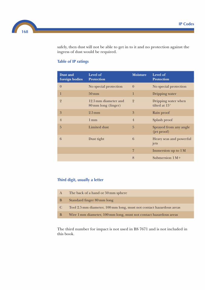
safely, then dust will not be able to get in to it and no protection against theingress of dust would be required.
Table of IP ratings
IP Codes
168
Dust and Level of Moisture Level offoreign bodies Protection Protection
0 No special protection 0 No special protection
1 50 mm 1 Dripping water
2 12.5 mm diameter and 2 Dripping water when80 mm long (finger) tilted at 15°
3 2.5 mm 3 Rain proof
4 1 mm 4 Splash proof
5 Limited dust 5 Sprayed from any angle(jet proof)
6 Dust tight 6 Heavy seas and powerfuljets
7 Immersion up to 1 M
8 Submersion 1 M�
A The back of a hand or 50 mm sphere
B Standard finger 80 mm long
C Tool 2.5 mm diameter, 100 mm long, must not contact hazardous areas
B Wire 1 mm diameter, 100 mm long, must not contact hazardous areas
Third digit, usually a letter
The third number for impact is not used in BS 7671 and is not included inthis book.
Exercises3
Exercise 1
Mrs F. G. Grant who lives in Bath, Somerset, has asked you to install a new32 A/230 V cooker circuit installed in the Kitchen.
The cooker control unit incorporates a 13 amp socket outlet. The existinginstallation is in good condition and complies with BS 7671, 2001 amended to2004. A recent Periodic Test Report, Schedules of Inspection and Test Results areavailable.
The wiring for the new circuit is 6 mm2 thermoplastic (pvc) flat twin withCPC cable. The circuit protection is by a type B32A RCBO to BS EN 61009which has a maximum ZS of 1.5 ohms and an Icn rating of 6 kA. Thisprotective device is housed in a consumer unit, which is situated in theintegral garage of the house. The main switch is BS EN 60439,100 A 230 V.
The ambient temperature is 20°C, R2 � R2 value for this cable is 10.49 milli-ohmsper metre, the circuit is 32 metres long.
The supply is TN-S 230 V 50 Hz, the main fuse is 100A BS 1361, and themeasured values of PFC and Ze are 800 amp and 0.24 ohms, respectively. Thesupply tails are 25 mm2 copper; the earthing conductor is 16 mm2 copper; andthe main equipotential bonding to gas and water is 10 mm2 copper. Maximumdemand is 85 amps.
Appendix
B
The Measured ZS is 0.48 Ω and an insulation test on all conductors shows�200 M ohms. RCD operating times are 43 ms at 30 mA and 19 ms at 150 mA.
A visual inspection shows no defects and the test instruments are: Lowresistance ohm and insulation resistance meter Serial no. 08H46. Earth loopimpedance tester Serial no. 076H90. RCD tester Serial number 740026.
1. Complete a schedule of inspections.2. Complete a schedule of test results.3. Complete the appropriate certificate.4. Using the rule of thumb, show if the measured value of ZS is acceptable.
Give a reason/reasons why this measured value is lower than Ze � (R1 � R2).5. If cooker unit had been a replacement for a unit without a socket outlet,
complete the Minor Works Certificate.6. Describe in detail how an earth loop impedance test would be carried out
on this circuit.
Exercise 2
You have installed a new ring circuit consisting of eight socket outlets on the groundfloor of a detached house for Mr. Hawth who resides in Crawley, Hampshire.
There is no documentation available for the existing installation, but itappears to be in good condition. There is space available in the existingconsumer’s unit for a new circuit.
The supply is a TNCS 230 V 50 Hz single phase with an 80 amp supply fuse toBS 1361. Measured values of PSCC and Ze are 1350A and 0.28 Ω, respectively.On completion of the additional work the maximum demand is 78 amps.
Meter tails are 16 mm2 copper, the earthing conductor is 10 mm2 copper, andthe main equipotential bonding conductors to the oil and water supplies are10 mm2 (correctly connected).
The new circuit is wired in 63 metres of 2.5 mm2/1.5 mm2 thermoplastic (pvc)twin and earth cable. Protection is by a 30A BS 3036 semi-enclosed rewirablefuse which has a maximum ZS value of 1.14 Ω. The consumer’s unit, situatedin a cupboard in the hall, has a 100A BS EN 61008-1 RCD as a main switchwith an IΔn rating of 30 mA. It has a tripping time of 56 ms at its rating and24 ms at five times its rating. The insulation resistance value is �200 MΩ.
Exercises
170
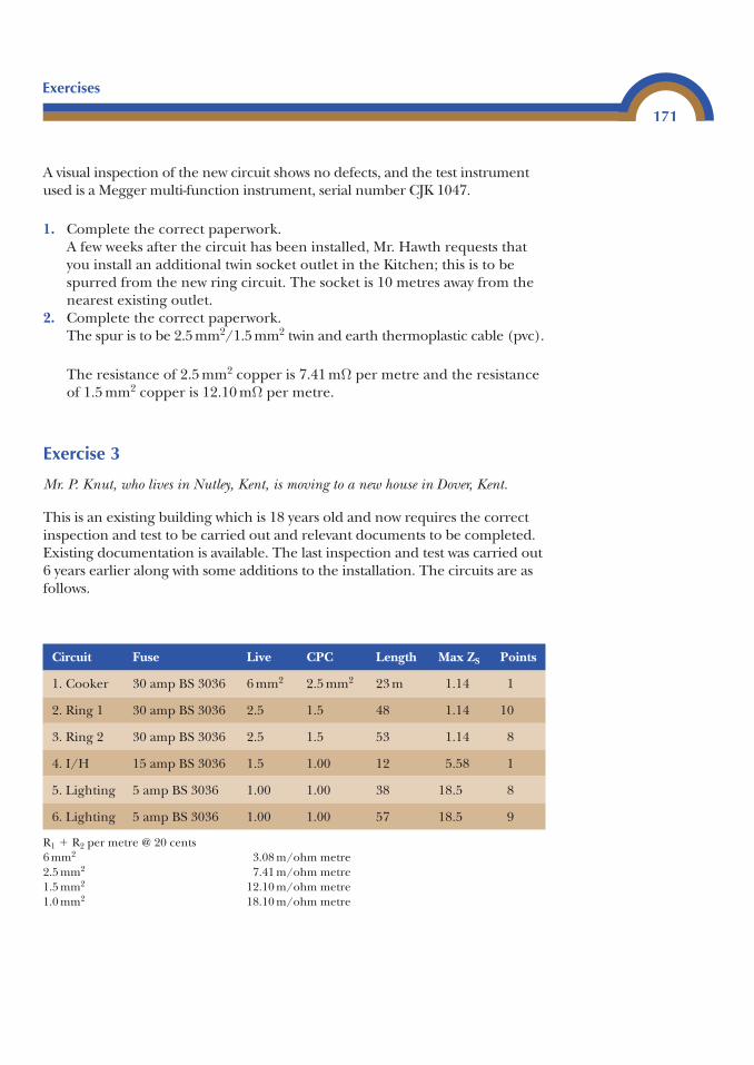
A visual inspection of the new circuit shows no defects, and the test instrumentused is a Megger multi-function instrument, serial number CJK 1047.
1. Complete the correct paperwork.A few weeks after the circuit has been installed, Mr. Hawth requests thatyou install an additional twin socket outlet in the Kitchen; this is to bespurred from the new ring circuit. The socket is 10 metres away from thenearest existing outlet.
2. Complete the correct paperwork.The spur is to be 2.5 mm2/1.5 mm2 twin and earth thermoplastic cable (pvc).
The resistance of 2.5 mm2 copper is 7.41 mΩ per metre and the resistanceof 1.5 mm2 copper is 12.10 mΩ per metre.
Exercise 3
Mr. P. Knut, who lives in Nutley, Kent, is moving to a new house in Dover, Kent.
This is an existing building which is 18 years old and now requires the correctinspection and test to be carried out and relevant documents to be completed.Existing documentation is available. The last inspection and test was carried out6 years earlier along with some additions to the installation. The circuits are asfollows.
Exercises
171
Circuit Fuse Live CPC Length Max ZS Points
1. Cooker 30 amp BS 3036 6 mm2 2.5 mm2 23 m 1.14 1
2. Ring 1 30 amp BS 3036 2.5 1.5 48 1.14 10
3. Ring 2 30 amp BS 3036 2.5 1.5 53 1.14 8
4. I/H 15 amp BS 3036 1.5 1.00 12 5.58 1
5. Lighting 5 amp BS 3036 1.00 1.00 38 18.5 8
6. Lighting 5 amp BS 3036 1.00 1.00 57 18.5 9
R1 � R2 per metre @ 20 cents6 mm2 3.08 m/ohm metre2.5 mm2 7.41 m/ohm metre1.5 mm2 12.10 m/ohm metre1.0 mm2 18.10 m/ohm metre
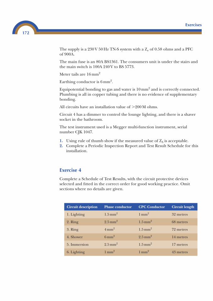
The supply is a 230 V 50 Hz TN-S system with a Ze of 0.58 ohms and a PFC of 900A.
The main fuse is an 80A BS1361. The consumers unit is under the stairs andthe main switch is 100A 240 V to BS 5773.
Meter tails are 16 mm2
Earthing conductor is 6 mm2.
Equipotential bonding to gas and water is 10 mm2 and is correctly connected.Plumbing is all in copper tubing and there is no evidence of supplementarybonding.
All circuits have an installation value of �200 M ohms.
Circuit 4 has a dimmer to control the lounge lighting, and there is a shaversocket in the bathroom.
The test instrument used is a Megger multi-function instrument, serialnumber CJK 1047.
1. Using rule of thumb show if the measured value of ZS is acceptable.2. Complete a Periodic Inspection Report and Test Result Schedule for this
installation.
Exercise 4
Complete a Schedule of Test Results, with the circuit protective devicesselected and fitted in the correct order for good working practice. Omitsections where no details are given.
Exercises
172
Circuit description Phase conductor CPC Conductor Circuit length
1. Lighting 1.5 mm2 1 mm2 32 metres
2. Ring 2.5 mm2 1.5 mm2 68 metres
3. Ring 4 mm2 1.5 mm2 72 metres
4. Shower 6 mm2 2.5 mm2 14 metres
5. Immersion 2.5 mm2 1.5 mm2 17 metres
6. Lighting 1 mm2 1 mm2 43 metres
Supply system is TN-S 230 volt measured ZS is 0.43 Ω, and PFC is 1.2 kA.
All circuits are protected by BS EN 60898 type B circuit breaker.
Exercise 5
Use BS 7671 to find the regulation number indicating where RCDs should beused and what trip rating they should have for:
• Fire protection on farms• Protection where flammable materials are stored• Fixed equipment in Zones 1–3 in bathrooms• Restrictive conductive locations• TT systems• Circuits with a high earth fault loop impedance (ZS)• Caravan parks• Sockets likely to supply portable equipment used out doors• Swimming pools
Exercises
173

This page intentionally left blank
Questions 3
1. An insulation resistance test has been carried out on a 6-way consumer’sunit. The circuits recorded values of 5.6 mΩ, 8.7 mΩ, �200 mΩ, �200 mΩ,12 mΩ and 7 mΩ.Calculate the total resistance of the installation and state giving reasonswhether or not the installation is acceptable.
2. A ring circuit is 54 metres long and is wired in 2.5 mm2/1.5 mm2
thermoplastic cable. The protective device is a BS EN 60898 type C deviceand the Ze for the installation is 0.24Ω. The resistance of 2.5 mm2 copperis 7.41 mΩ per metre and 1.5 mm2 copper is 12.1 mΩ per metre. (i) Calculate the ZS for the circuit.(ii) Will the protective device be suitable?
3. An A2 radial circuit is wired in 4 mm2 thermoplastic twin and earth cable.It is 23 metres long. The circuit has on it four twin 13 amp socket outlets.Protection is by a 30A BS 3036 semi-enclosed fuse. Ze for the installation is0.6 Ω.Socket 1 is 12 metres from the consumer unit, socket 2 is 6 metres fromsocket 1, and socket 3 is 2.5 metres from socket 2.(i) Calculate the R1 � R2 value at each socket outlet.(ii) Will the circuit protective device be suitable?
4. A 9.5 kW electric shower has been installed using 10 mm2/4 mm2
thermoplastic twin and earth cable which is 14.75 metres long. The circuitis to be connected to a spare way in the existing consumer’s unit.
Appendix
C
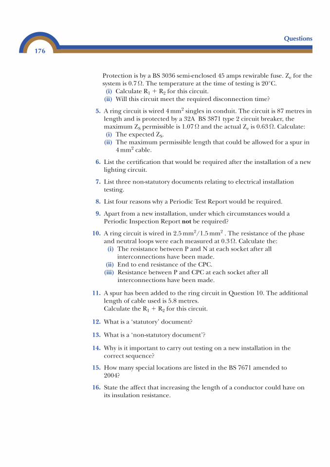
Protection is by a BS 3036 semi-enclosed 45 amps rewirable fuse. Ze for thesystem is 0.7 Ω. The temperature at the time of testing is 20°C.(i) Calculate R1 � R2 for this circuit.(ii) Will this circuit meet the required disconnection time?
5. A ring circuit is wired 4 mm2 singles in conduit. The circuit is 87 metres inlength and is protected by a 32A BS 3871 type 2 circuit breaker, themaximum ZS permissible is 1.07 Ω and the actual Ze is 0.63 Ω. Calculate:(i) The expected ZS.(ii) The maximum permissible length that could be allowed for a spur in
4 mm2 cable.
6. List the certification that would be required after the installation of a newlighting circuit.
7. List three non-statutory documents relating to electrical installationtesting.
8. List four reasons why a Periodic Test Report would be required.
9. Apart from a new installation, under which circumstances would aPeriodic Inspection Report not be required?
10. A ring circuit is wired in 2.5 mm2/1.5 mm2 . The resistance of the phaseand neutral loops were each measured at 0.3 Ω. Calculate the:(i) The resistance between P and N at each socket after all
interconnections have been made.(ii) End to end resistance of the CPC.
(iii) Resistance between P and CPC at each socket after allinterconnections have been made.
11. A spur has been added to the ring circuit in Question 10. The additionallength of cable used is 5.8 metres.Calculate the R1 � R2 for this circuit.
12. What is a ‘statutory’ document?
13. What is a ‘non-statutory document’?
14. Why is it important to carry out testing on a new installation in thecorrect sequence?
15. How many special locations are listed in the BS 7671 amended to2004?
16. State the affect that increasing the length of a conductor could have onits insulation resistance.
Questions
176
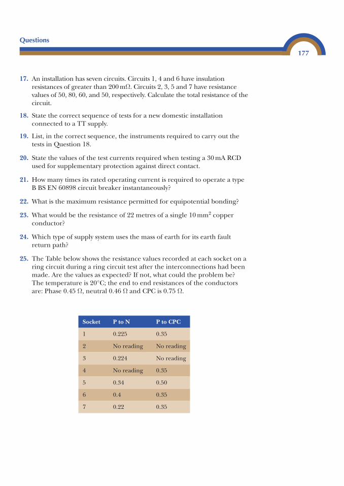
17. An installation has seven circuits. Circuits 1, 4 and 6 have insulationresistances of greater than 200 mΩ. Circuits 2, 3, 5 and 7 have resistancevalues of 50, 80, 60, and 50, respectively. Calculate the total resistance of thecircuit.
18. State the correct sequence of tests for a new domestic installationconnected to a TT supply.
19. List, in the correct sequence, the instruments required to carry out thetests in Question 18.
20. State the values of the test currents required when testing a 30 mA RCDused for supplementary protection against direct contact.
21. How many times its rated operating current is required to operate a typeB BS EN 60898 circuit breaker instantaneously?
22. What is the maximum resistance permitted for equipotential bonding?
23. What would be the resistance of 22 metres of a single 10 mm2 copperconductor?
24. Which type of supply system uses the mass of earth for its earth faultreturn path?
25. The Table below shows the resistance values recorded at each socket on aring circuit during a ring circuit test after the interconnections had beenmade. Are the values as expected? If not, what could the problem be?The temperature is 20°C; the end to end resistances of the conductorsare: Phase 0.45 Ω, neutral 0.46 Ω and CPC is 0.75 Ω.
Questions
177
Socket P to N P to CPC
1 0.225 0.35
2 No reading No reading
3 0.224 No reading
4 No reading 0.35
5 0.34 0.50
6 0.4 0.35
7 0.22 0.35
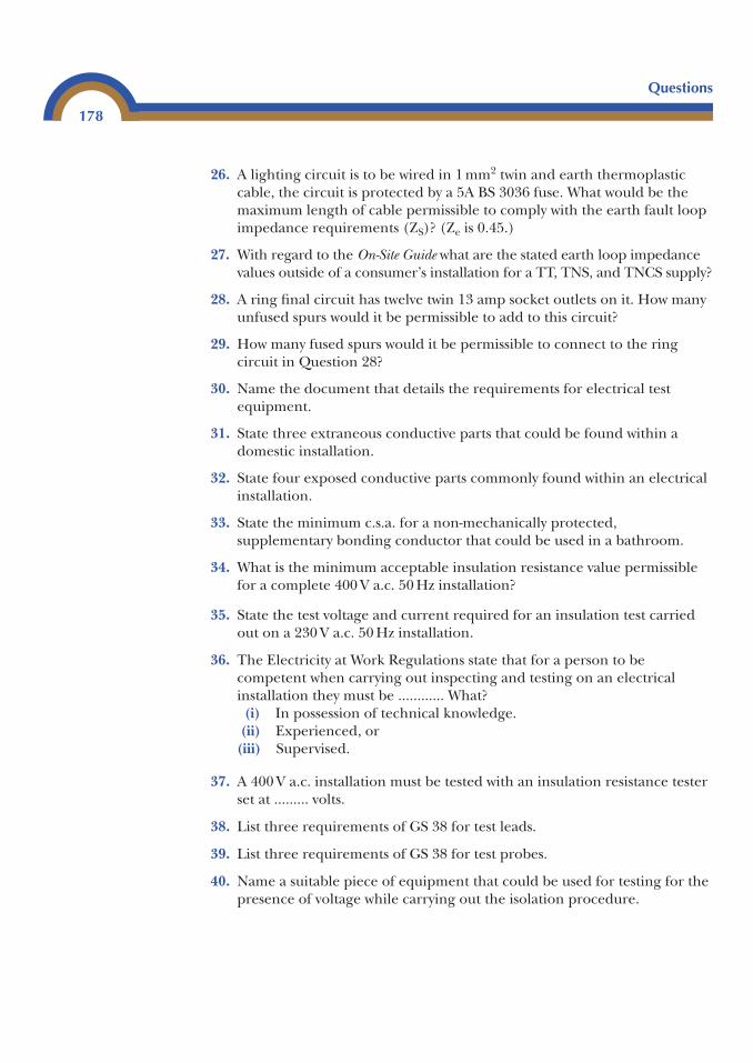
26. A lighting circuit is to be wired in 1 mm2 twin and earth thermoplasticcable, the circuit is protected by a 5A BS 3036 fuse. What would be themaximum length of cable permissible to comply with the earth fault loopimpedance requirements (ZS)? (Ze is 0.45.)
27. With regard to the On-Site Guide what are the stated earth loop impedancevalues outside of a consumer’s installation for a TT, TNS, and TNCS supply?
28. A ring final circuit has twelve twin 13 amp socket outlets on it. How manyunfused spurs would it be permissible to add to this circuit?
29. How many fused spurs would it be permissible to connect to the ringcircuit in Question 28?
30. Name the document that details the requirements for electrical testequipment.
31. State three extraneous conductive parts that could be found within adomestic installation.
32. State four exposed conductive parts commonly found within an electricalinstallation.
33. State the minimum c.s.a. for a non-mechanically protected,supplementary bonding conductor that could be used in a bathroom.
34. What is the minimum acceptable insulation resistance value permissiblefor a complete 400 V a.c. 50 Hz installation?
35. State the test voltage and current required for an insulation test carriedout on a 230 V a.c. 50 Hz installation.
36. The Electricity at Work Regulations state that for a person to becompetent when carrying out inspecting and testing on an electricalinstallation they must be ............ What?(i) In possession of technical knowledge.(ii) Experienced, or(iii) Supervised.
37. A 400 V a.c. installation must be tested with an insulation resistance testerset at ......... volts.
38. List three requirements of GS 38 for test leads.
39. List three requirements of GS 38 for test probes.
40. Name a suitable piece of equipment that could be used for testing for thepresence of voltage while carrying out the isolation procedure.
Questions
178
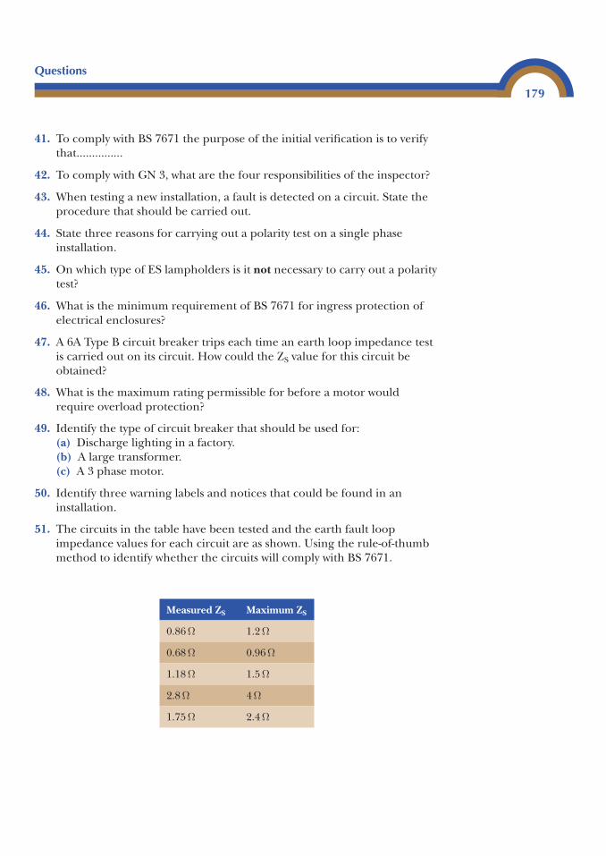
41. To comply with BS 7671 the purpose of the initial verification is to verifythat...............
42. To comply with GN 3, what are the four responsibilities of the inspector?
43. When testing a new installation, a fault is detected on a circuit. State theprocedure that should be carried out.
44. State three reasons for carrying out a polarity test on a single phaseinstallation.
45. On which type of ES lampholders is it not necessary to carry out a polaritytest?
46. What is the minimum requirement of BS 7671 for ingress protection ofelectrical enclosures?
47. A 6A Type B circuit breaker trips each time an earth loop impedance testis carried out on its circuit. How could the ZS value for this circuit beobtained?
48. What is the maximum rating permissible for before a motor wouldrequire overload protection?
49. Identify the type of circuit breaker that should be used for:(a) Discharge lighting in a factory.(b) A large transformer.(c) A 3 phase motor.
50. Identify three warning labels and notices that could be found in aninstallation.
51. The circuits in the table have been tested and the earth fault loopimpedance values for each circuit are as shown. Using the rule-of-thumbmethod to identify whether the circuits will comply with BS 7671.
Questions
179
Measured ZS Maximum ZS
0.86 Ω 1.2 Ω
0.68 Ω 0.96 Ω
1.18 Ω 1.5 Ω
2.8 Ω 4 Ω
1.75 Ω 2.4 Ω
Questions
180
52. State the minimum IP rating for fixed equipment in Zone 2 of abathroom.
53. State the minimum size for an equipotential bonding conductor installedin a TNS system with 25 mm2 metre tails.
54. Identify the documentation that should be completed after theinstallation of a cooker circuit.
55. State four non-statutory documents.
56. State four statutory documents.
57. State the sequence of colours for a new 3 phase and neutral system.
Answers to Exercises3
(The Certificates can be found at the end of the chapter)
Exercise 1
1. and 2. Part P – Domestic Electrical Installation Certificate – Part 2.3. Part P – Domestic Electrical Installation Certificate.4. 1.92 � 0.75 � 1.44 Ω. This is the maximum permissible ZS for a
BS 88 32 amp fuse. As the measured value of ZS was 0.48 Ω this circuitis fine.The measured ZS is lower due to parallel paths through the bondingconductors, etc.
5. Minor Domestic Electrical Installation Works Certificate.6. Use an earth fault loop impedance test instrument set on loop, plug lead
into socket outlet on cooker control unit and take earth loop impedancereading.
Exercise 2
1. Part P – Domestic Electrical Installation Certificate; Part P – DomesticElectrical Installation Certificate – Part 2.
2. Minor Domestic Electrical Installation Works Certificate.
Appendix
D
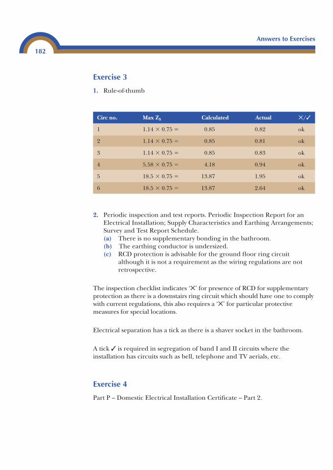
Exercise 3
1. Rule-of-thumb
Circ no. Max ZS Calculated Actual ✕/✓
1 1.14 � 0.75 � 0.85 0.82 ok
2 1.14 � 0.75 � 0.85 0.81 ok
3 1.14 � 0.75 � 0.85 0.83 ok
4 5.58 � 0.75 � 4.18 0.94 ok
5 18.5 � 0.75 � 13.87 1.95 ok
6 18.5 � 0.75 � 13.87 2.64 ok
2. Periodic inspection and test reports. Periodic Inspection Report for anElectrical Installation; Supply Characteristics and Earthing Arrangements;Survey and Test Report Schedule.(a) There is no supplementary bonding in the bathroom.(b) The earthing conductor is undersized.(c) RCD protection is advisable for the ground floor ring circuit
although it is not a requirement as the wiring regulations are notretrospective.
The inspection checklist indicates ‘✕’ for presence of RCD for supplementaryprotection as there is a downstairs ring circuit which should have one to complywith current regulations, this also requires a ‘✕’ for particular protectivemeasures for special locations.
Electrical separation has a tick as there is a shaver socket in the bathroom.
A tick ✓ is required in segregation of band I and II circuits where theinstallation has circuits such as bell, telephone and TV aerials, etc.
Exercise 4
Part P – Domestic Electrical Installation Certificate – Part 2.
Answers to Exercises
182
Exercise 5
(a) Used for fire protection 500 mA (Regulation 605-10-01).(b) Particular risk of danger of fire exist 300 mA (Regulation 482-02-06).(c) Bathroom is a special location, Regulation 601-09 requires the use of a
30 mA RCD.(d) An RCD is not permitted as a form of protection in a restrictive
conductive location.(e) TT system should preferably use a split board with RCD rated at 100 mA
for fixed equipment and 30 mA for socket outlets (On-Site Guide).(f) Where a circuit has high loop impedance a 100 mA RCD is suitable
providing it is not for socket outlets that could be used outside and thatthe circuit is not in a special location.
(g) Caravan park is a special location, Regulation 608-13-05 requires the useof a 30 mA RCD.
(h) Regulation 471-16-01 refers to Regulation 412-06-02 which requires theuse of a 30 mA RCD.
(i) Regulation 602-04-01(ii) refers to Regulation 412-06-02 which requires theuse of a 30 mA RCD installed in accordance with Regulations 602-07-01and 602-07-02(iii).
Answers to Exercises
183
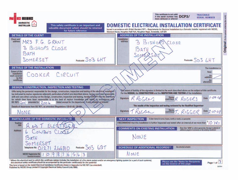
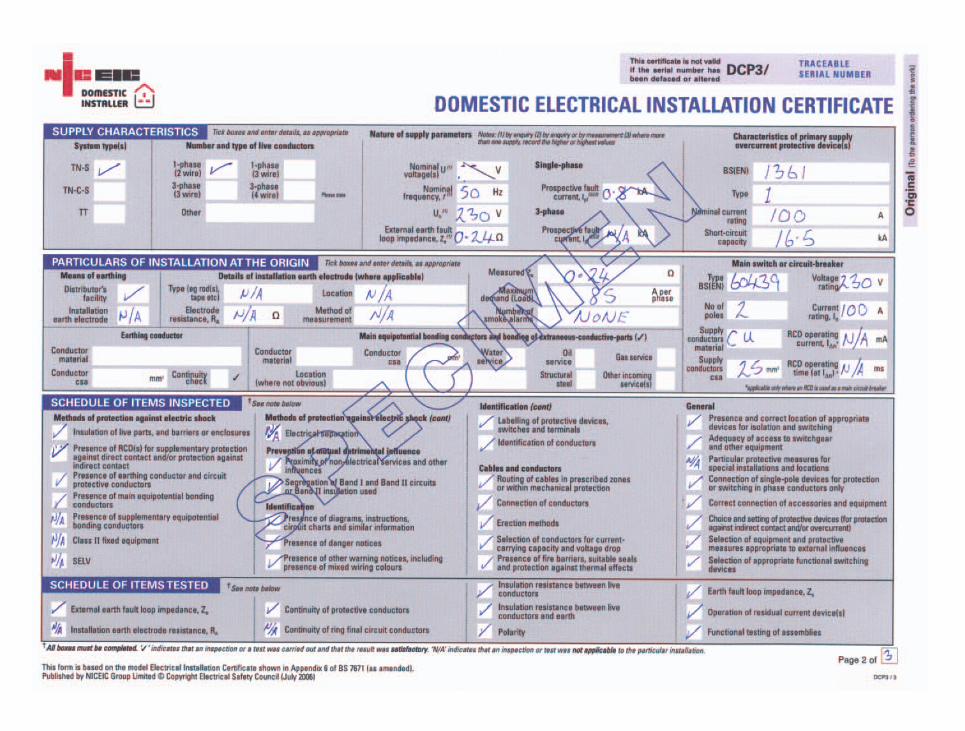
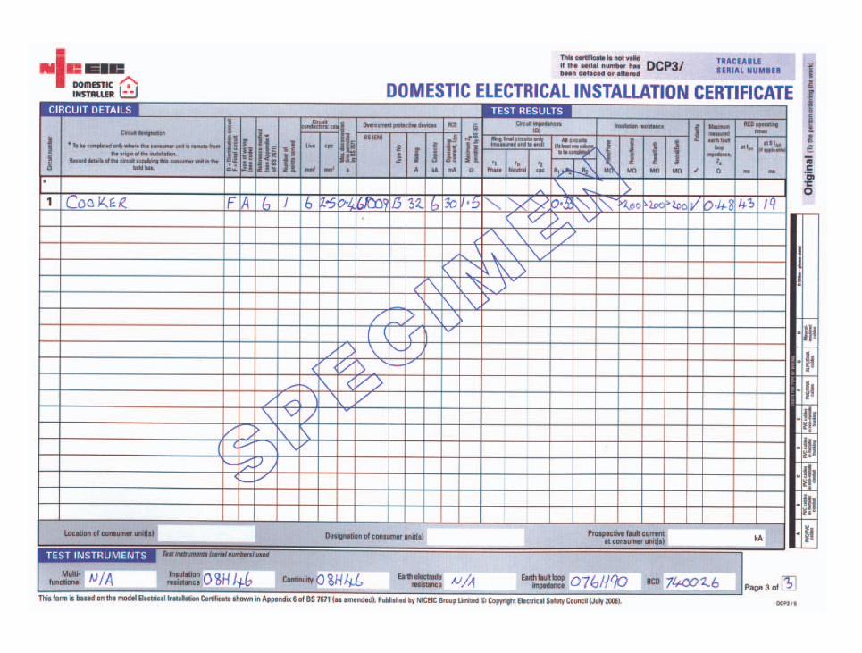
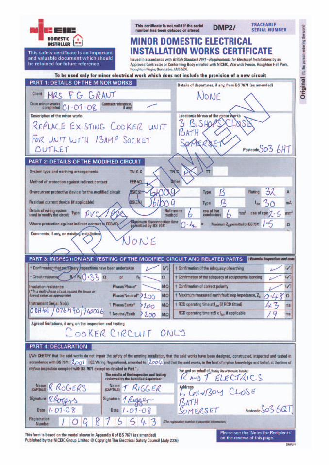
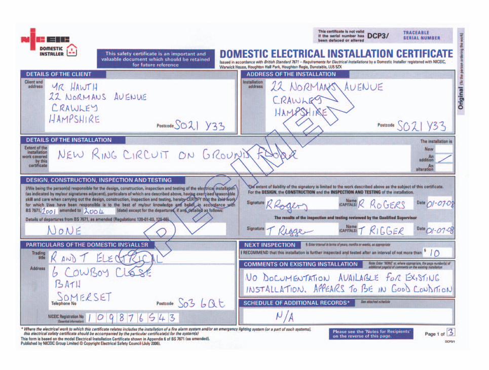
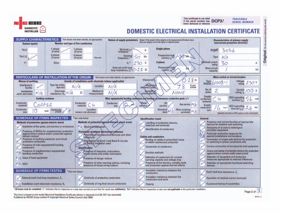
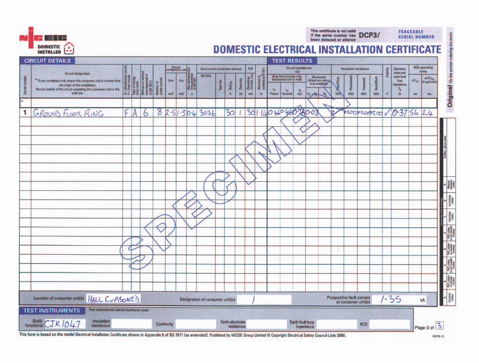
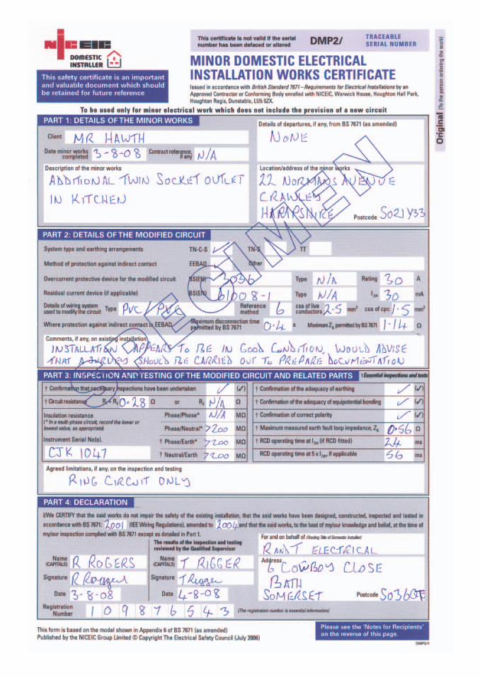
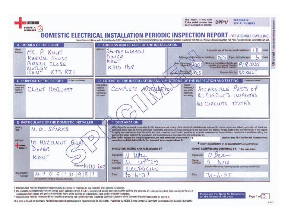
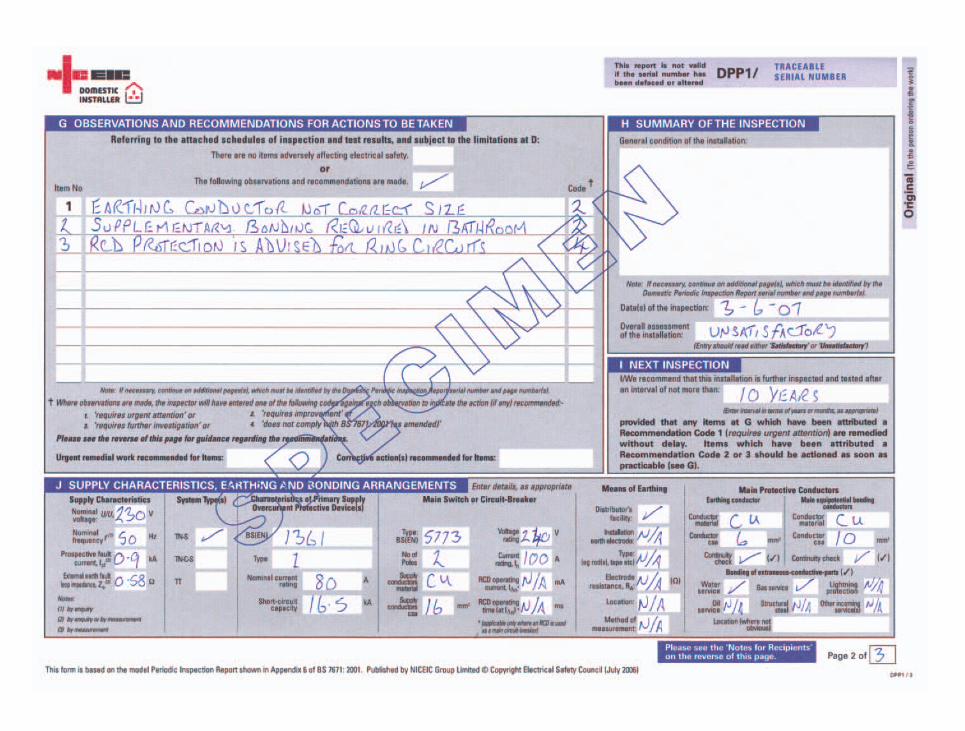
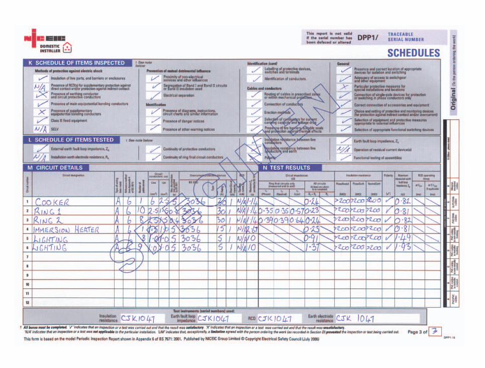
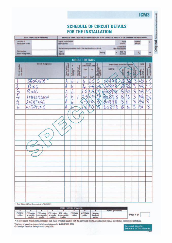
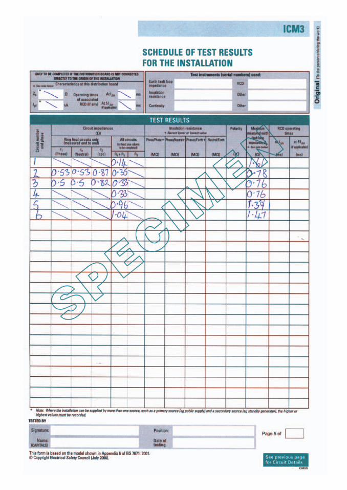
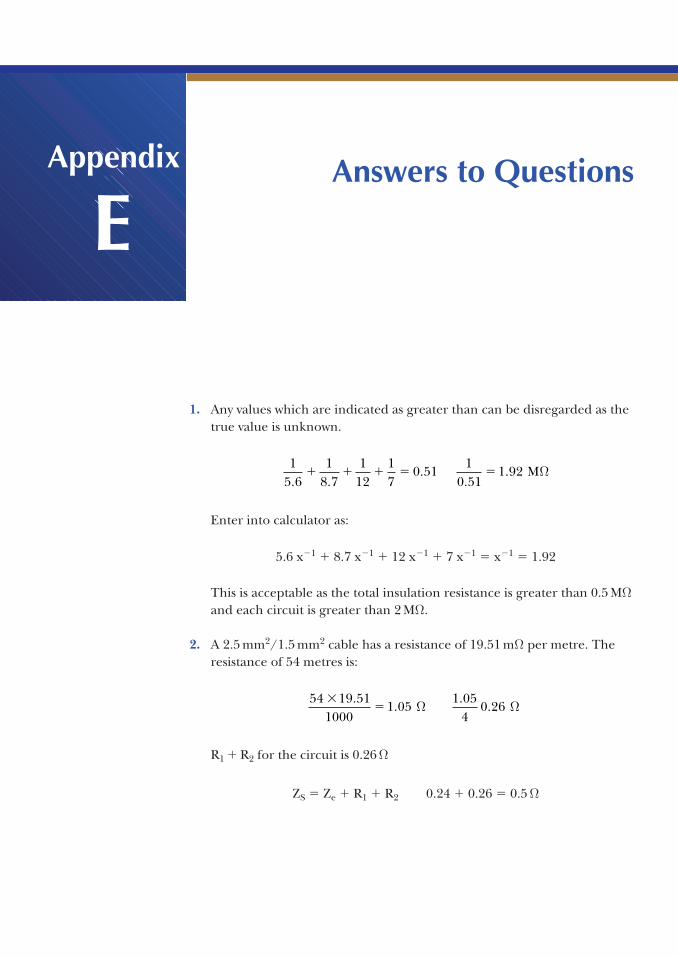
Answers to Questions3
1. Any values which are indicated as greater than can be disregarded as thetrue value is unknown.
Enter into calculator as:
5.6 x�1 � 8.7 x�1 � 12 x�1 � 7 x�1 � x�1 � 1.92
This is acceptable as the total insulation resistance is greater than 0.5 MΩand each circuit is greater than 2 MΩ.
2. A 2.5 mm2/1.5 mm2 cable has a resistance of 19.51 mΩ per metre. Theresistance of 54 metres is:
R1 � R2 for the circuit is 0.26 Ω
ZS � Ze � R1 � R2 0.24 � 0.26 � 0.5 Ω
54 19 511000
1 051 05
40 26
��
..
..Ω Ω
15 6
18 7
112
17
0 511
0 511 92
. ..
..� � � � � MΩ
Appendix
E
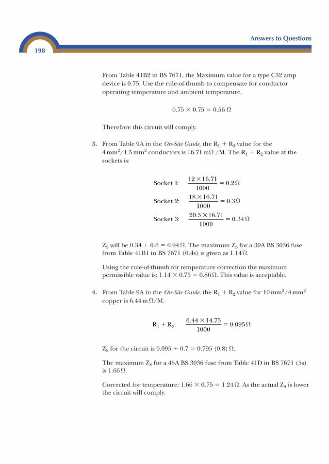
From Table 41B2 in BS 7671, the Maximum value for a type C32 ampdevice is 0.75. Use the rule-of-thumb to compensate for conductoroperating temperature and ambient temperature.
0.75 � 0.75 � 0.56 Ω
Therefore this circuit will comply.
3. From Table 9A in the On-Site Guide, the R1 � R2 value for the4 mm2/1.5 mm2 conductors is 16.71 mΩ /M. The R1 � R2 value at thesockets is:
ZS will be 0.34 � 0.6 � 0.94 Ω. The maximum ZS for a 30A BS 3036 fusefrom Table 41B1 in BS 7671 (0.4s) is given as 1.14Ω.
Using the rule-of-thumb for temperature correction the maximumpermissible value is: 1.14 � 0.75 � 0.86 Ω. This value is acceptable.
4. From Table 9A in the On-Site Guide, the R1 � R2 value for 10 mm2/4 mm2
copper is 6.44 m Ω/M.
ZS for the circuit is 0.095 � 0.7 � 0.795 (0.8) Ω.
The maximum ZS for a 45A BS 3036 fuse from Table 41D in BS 7671 (5s) is 1.66 Ω.
Corrected for temperature: 1.66 � 0.75 � 1.24 Ω. As the actual ZS is lowerthe circuit will comply.
R R :1 26 44 14 75
10000 095�
��
. .. Ω
Socket :
Socket :
112 16 71
10000 2
218 16 71
��
�
..
.
Ω
11000
Socket :
�
��
0 3
320 5 16 71
10000 34
.
. ..
Ω
Ω
Answers to Questions
198
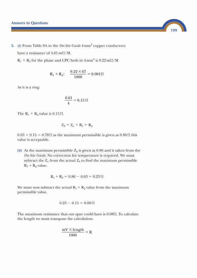
5. (i) From Table 9A in the On-Site Guide 4 mm2 copper conductors:
have a resistance of 4.61 mΩ/M.
R1 � R2 for the phase and CPC both in 4 mm2 is 9.22 mΩ/M
As it is a ring:
The R1 � R2 value is 0.15 Ω.
ZS � Ze � R1 � R2
0.63 � 0.15 � 0.78Ω as the maximum permissible is given as 0.86 Ω thisvalue is acceptable.
(ii) As the maximum permissible ZS is given as 0.86 and is taken from the On-Site Guide. No correction for temperature is required. We mustsubtract the Ze from the actual ZS to find the maximum permissibleR1 � R2 value.
R1 � R2 � 0.86 � 0.63 � 0.23 Ω
We must now subtract the actual R1 � R2 value from the maximumpermissible value.
0.23 � 0.15 � 0.08 Ω
The maximum resistance that our spur could have is 0.08Ω. To calculatethe length we must transpose the calculation:
mV lengthR
��
1000
0 614
0 15.
.� Ω
R R :1 29 22 67
10000 061�
��
.. Ω
Answers to Questions
199
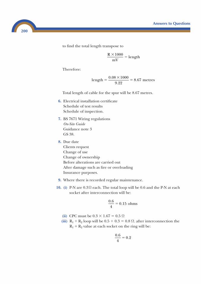
to find the total length transpose to
Therefore:
Total length of cable for the spur will be 8.67 metres.
6. Electrical installation certificateSchedule of test resultsSchedule of inspection.
7. BS 7671 Wiring regulationsOn-Site GuideGuidance note 3GS 38.
8. Due dateClients requestChange of useChange of ownershipBefore alterations are carried outAfter damage such as fire or overloadingInsurance purposes.
9. Where there is recorded regular maintenance.
10. (i) P-N are 0.3Ω each. The total loop will be 0.6 and the P-N at eachsocket after interconnection will be:
(ii) CPC must be 0.3 � 1.67 � 0.5 Ω(iii) R1 � R2 loop will be 0.5 � 0.3 � 0.8 Ω. after interconnection the
R1 � R2 value at each socket on the ring will be:
0 64
0 2.
.�
0 64
0 15.
.� ohms
length metres��
�0 08 1000
9 228 67
..
.
RmV
length�
�1000
Answers to Questions
200
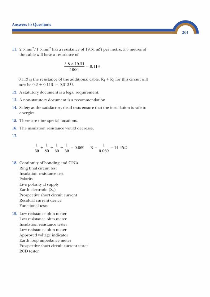
11. 2.5 mm2/1.5 mm2 has a resistance of 19.51 mΩ per metre. 5.8 metres ofthe cable will have a resistance of:
0.113 is the resistance of the additional cable. R1 � R2 for this circuit willnow be 0.2 � 0.113 � 0.313 Ω.
12. A statutory document is a legal requirement.
13. A non-statutory document is a recommendation.
14. Safety as the satisfactory dead tests ensure that the installation is safe toenergize.
15. There are nine special locations.
16. The insulation resistance would decrease.
17.
18. Continuity of bonding and CPCsRing final circuit testInsulation resistance testPolarityLive polarity at supplyEarth electrode (Ze)Prospective short circuit currentResidual current deviceFunctional tests.
19. Low resistance ohm meterLow resistance ohm meterInsulation resistance testerLow resistance ohm meterApproved voltage indicatorEarth loop impedance meterProspective short circuit current testerRCD tester.
150
180
160
150
0 0691
0 06914 45� � � � � �.
..R Ω
5 8 19 511000
0 113. .
.�
�
Answers to Questions
201
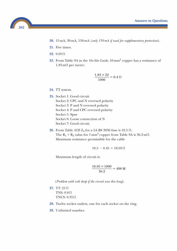
20. 15 mA, 30 mA, 150 mA (only 150 mA if used for supplementary protection).
21. Five times.
22. 0.05Ω.
23. From Table 9A in the On-Site Guide, 10 mm2 copper has a resistance of1.83 mΩ per metre:
24. TT system.
25. Socket 1: Good circuitSocket 2: CPC and N reversed polaritySocket 3: P and N reversed polaritySocket 4: P and CPC reversed polaritySocket 5: SpurSocket 6: Loose connection of NSocket 7: Good circuit.
26. From Table 41D ZS for a 5A BS 3036 fuse is 18.5 Ω.The R1 � R2 value for 1 mm2 copper from Table 9A is 36.2 mΩ.Maximum resistance permissible for the cable
18.5 � 0.45 � 18.05Ω
Maximum length of circuit is:
(Problem with volt drop if the circuit was this long).
27. TT: 21ΩTNS: 0.8ΩTNCS: 0.35Ω
28. Twelve socket outlets, one for each socket on the ring.
29. Unlimited number.
18 05 100036 2
498.
.�
� M
1 83 221000
0 4.
.�
� Ω
Answers to Questions
202
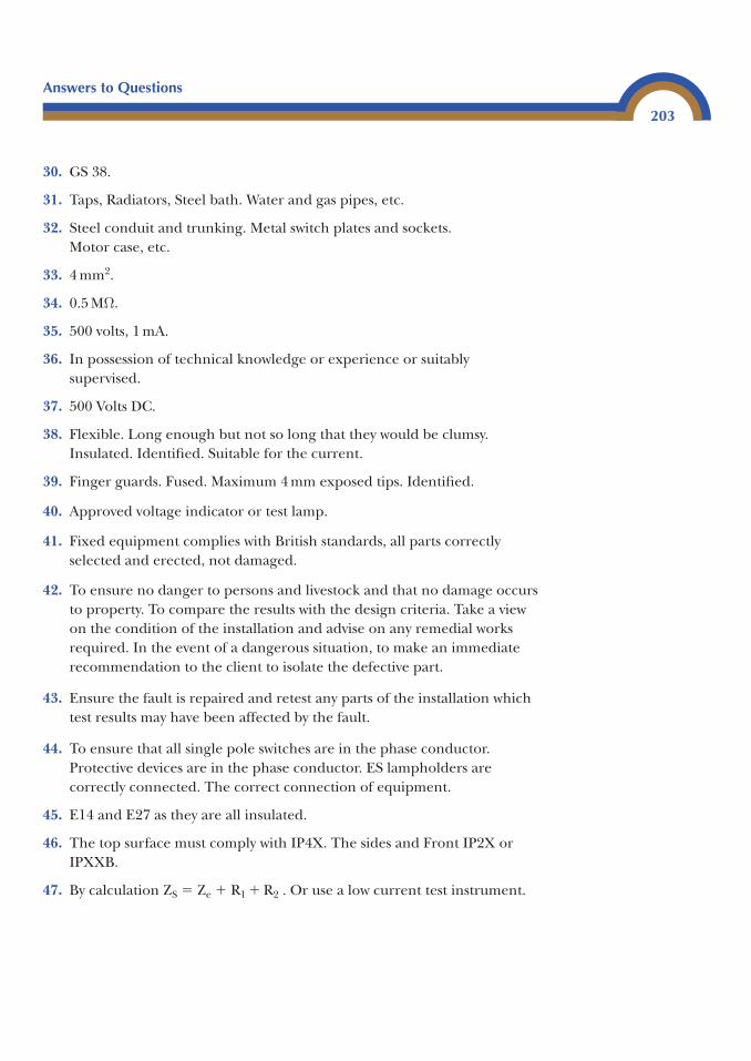
30. GS 38.
31. Taps, Radiators, Steel bath. Water and gas pipes, etc.
32. Steel conduit and trunking. Metal switch plates and sockets. Motor case, etc.
33. 4 mm2.
34. 0.5 MΩ.
35. 500 volts, 1 mA.
36. In possession of technical knowledge or experience or suitablysupervised.
37. 500 Volts DC.
38. Flexible. Long enough but not so long that they would be clumsy.Insulated. Identified. Suitable for the current.
39. Finger guards. Fused. Maximum 4 mm exposed tips. Identified.
40. Approved voltage indicator or test lamp.
41. Fixed equipment complies with British standards, all parts correctlyselected and erected, not damaged.
42. To ensure no danger to persons and livestock and that no damage occursto property. To compare the results with the design criteria. Take a viewon the condition of the installation and advise on any remedial worksrequired. In the event of a dangerous situation, to make an immediaterecommendation to the client to isolate the defective part.
43. Ensure the fault is repaired and retest any parts of the installation whichtest results may have been affected by the fault.
44. To ensure that all single pole switches are in the phase conductor.Protective devices are in the phase conductor. ES lampholders arecorrectly connected. The correct connection of equipment.
45. E14 and E27 as they are all insulated.
46. The top surface must comply with IP4X. The sides and Front IP2X orIPXXB.
47. By calculation ZS � Ze � R1 � R2 . Or use a low current test instrument.
Answers to Questions
203
48. 0.37 kW (Regulation 552-01-01).
49. (a) Type C(b) Type D(c) Type C
50. Safety electrical connection do not remove. Voltage in excess of 230 voltswhere not expected. Notice for RCD testing. Where isolation is notpossible by the use of a single device. Where different nominal voltagesexist. Periodic test date. Warning non-standard colours.
51. 1.2 � 0.75 � 0.9Ω0.96 � 0.75 � 0.72Ω1.5 � 0.75 � 1.125Ω4 � 0.75 � 3Ω2.4 � 0.75 � 1.8Ω
52. IP 4X
53. 10 mm2.
54. Electrical installation certificateSchedule of test resultsSchedule of inspection
55. BS 7671 (Electrical Wiring Regulations)On-Site GuideGS 38Guidance note 3
56. Health and Safety at Work Act 1974Electricity Supply RegulationsElectricity at Work Regulations 1989Construction Design and Management RegulationsBuilding Regulation Part P(Appendix 2 of BS 7671 covers statutory regulations).
57. Brown (L1), Black (L2), Grey (L3) and Blue (N).
Answers to Questions
204

Useful information3
The City and Guilds 2391 inspection and test exam is based on informationgiven in Guidance note 3, BS 7671 Wiring Regulations, the On-Site Guide andGS 38. It is important that any person intending to take this exam has a soundknowledge of these documents.
The 2391 101 written examination consists of two sections. The first section(A) contains 20 short answer questions. Of these 20 questions 15 will be ontesting, three will be on preparation of testing and two will be on the processof testing. Each question will be worth 3 marks. The question may be split intoparts each worth 1 mark or it may require a single answer worth 3 marks.
The second section (B) will consist of six questions, each worth 15 marks,these are long answer questions and are based on a scenario which is given atthe beginning of the section. Within each of the questions marks are given foreach correct part of the answer.
Section B of the paper will require in-depth answers; for example, thequestion could ask how you would carry out an insulation test on a domesticlighting circuit. It is easier to answer the question using bullet points as shownthan it is to write an essay.
• Ensure safety whilst test is being carried out.• Isolate circuit to be tested using the safe isolation procedure.• Remove all lamps.
Appendix
F
• If the removal of lamps is difficult or fluorescent/transformers are on thecircuit open the switches controlling them.
• Isolate or bypass all electronic equipment and equipment that may bedamaged or give false readings.
• Use an insulation resistance tester set on 500 V d.c.• Ensure instrument is accurate and operate the instrument with the leads
together and then apart to ensure correct operation.• Test circuit between live conductors.• Operate any two-way switches controlling points where lamps have been
removed.• Join live conductors together and test between them and earth.• Operate all two way switches.• The insulation resistance should be above 2 MΩ. If it is less, then further
investigation must be carried out as a latent defect may exist.• An insulation resistance value of 0.5 MΩ is acceptable in some cases.• Replace all lamps and remove any shorting links used.• Leave circuit safe and operational.
In any exam it is vital that the question is read carefully. Often it is better toread a question several times to try and understand what is being asked.
It is always better to show all calculations even if the question does not requireyou to. It is a good habit to get into and often you will get marks for showingthe correct calculation even if the answer is wrong.
If the question asks for a fully labelled diagram, then marks are awarded forthe diagram and the labelling. Where the question asks ‘explain with the aidof a diagram’ then a diagram and a written explanation is required.
When the question asks for a list then you will be expected to list a sequenceof events in the correct order. Just a list with no explanation. If you are requiredto state something then a statement is required in no particular order.
For example:
List the sequence of dead tests.
a. Continuity of bonding conductors and circuit protective conductors.b. Ring final circuit test.c. Insulation resistance test.d. Polarity.
Useful Information
206
State three statutory documents relating the inspecting and testing of elec-trical installations.
• The Electricity at Work Regulations 1989• The Health and Safety at Work Act 1974• The Electricity Supply Regulations.
Always try to answer the questions in full using the correct terminology; forexample: if asked “which is the type of inspection to be carried out on a newinstallation”, the answer must be: An initial verification. For the documentrequired for moving a switch or adding a socket the answer must be: Anelectrical installation minor works certificate, not just minor works.
Do not waste time copying out the question and write as clearly as you can.
Useful Information
207

This page intentionally left blank
Index
Bonding 5, 31, 35, 144British standard 1BS 7288 Socket outlets 100, 107BS7671 1
Calibration 158Certification 9Circuit breakers 151Competent person 6Consumers unit 18Continuity of CPCs 40Continuity of protective conductors
31, 40
Disconnection times 20, 152DIY installer 6Document P 1, 2, 4, 9Domestic electrical installation works
certificate 9
Earth clamp BS951 34Earth electrode testing 70Earth fault loop impedance (Zs) 79,
125, 126, 152, 157Earth fault loop path 74, 101, 163ELCB 99Electrical installation certificates 11,
115Electrical test certificates 1, 11Electricity at work regulations 1, 30Electric shock 160Equipotential bonding 31Exposed conductive parts 31External earth loop impedance (Ze) 73,
77Extraneous conductive parts 31, 39, 144
Fixed equipment 151Flooding 2Functional testing 98Fuses 150
GS 38 25, 77
Home information pack 3
Initial verification 11Induction motor testing 164Interconnections of ring 43Inspection 12Insulation resistance 51Insulation resistance values 52Insulation resistance, 3
phase installations 59IP Codes 167
Lampholders E14 & E47 62Legislation 3Live polarity 67
Main equipotential bonding 31Megohms 54, 157Method 1 (R1 � R2) 41Method 2 (Long lead method) 42Minor works certificate 9, 109
Non domestic certification 10Non notifiable work 3Notifiable work 3
Overcurrent 149Overcurrent protective devices 123Overload current 152
Part P domestic electrical installationcertificate 9, 115
PEN conductor 76Periodic inspection 10, 14, 136Periodic inspection report 13, 136Periodic testing 21PFC 13, 96Polarity 45, 62, 67Potential Difference 162Prospective earth fault current 92Prospective fault current 92, 151Prospective short circuit current 92Protection against Direct and Indirect
contact 130, 160Protection against direct contact 130,
162Protection against indirect contact 131,
162Protective devices 149Proving unit 25
RCCBO 101RCD Testing 105Recommended tests 22Registered competent person 6Registered domestic installer 5Residual current devices 98, 126Ring final circuit test 42 Rule of thumb 84, 182R1 � R2 19, 23, 41, 81, 125
Safe isolation 25, 28Schedule of inspection 127Schedule of test results 61, 121 SELV 164Sequence of tests 13Short circuit capacities 96, 97Split Boards 102Site applied insulation 62Statutory document 1Supplementary bonding 35Supply characteristics 119
Test equipment 156Test leads and probes 27Temperature correction 81Three Phase circuits 21Testing RCD’s 103Time delayed RCD 101TNCS 76, 103, 119TNS 75, 103, 119Transformer testing 164TT system 74, 101, 103, 119
Unregistered competent person 6
Voltage drop 23Visual inspection 12, 15, 17
Ze 13, 73, 77, 81, 103Zs 13, 79, 80, 81, 152
Index
210