95-7509-9 - excel 10...excel 5000Ž controller functions and also provides communication interface...
TRANSCRIPT

INSTALLATION INSTRUCTIONS
95-7509�9
Excel 10Q7750A ZONE MANAGER
WARNINGWarning: This equipment generates, uses and can radiate radio frequency energy and if not installed and used in accordance with the Instructions Manual, may cause interference with radio communications. It has been tested and found to comply with the limits for a Class A computing device pursuant to Subpart J of Part 15 or FCC Rules, which are designed to provide reasonable protection against such interference when operated in a commercial environment. Operation of this equipment in a residential area is likely to cause interference, in which case, users at their own expense will be required to take whatever measures may be required to correct the interference. Any unauthorized modification of this equipment may result in the revocation of the owner�s authority to continue its operation.
GENERALThe Q7750A Zone Manager is a controller that provides all Excel 5000� controller functions and also provides communication interface between an Excel 10 controller Echelon® LONWORKS® (E-Bus) subsystem and an Excel 5000 C-Bus system. The Q7750A Zone Manager can also be used as part of a smoke control system monitoring and control for monitor and control of fire (UL 864) and general purpose signaling (UL 2017). In UL 2017 applications, the product can be used as a type SM (Self-Monitored) system.
This controller can be used for smoke control applications when used in conjunction with a UL listed fire alarm control panel (FACP) and UL listed fire fighters� smoke control station (FSCS).
BEFORE INSTALLATIONThese Installation Instructions are applicable for the Q7750A Excel 10 Zone Manager2000-series-Free Topology E-Bus transceiver, including revision 2 software.Only trained technicians are allowed to work on the installation of the Q7750A hardware and to change the EPROMs or the Submodule within the hardware. The Q7750A Excel 10 Zone Manager is fully assembled and tested at the Honeywell Factory
Parts Checklist� Q7750A Excel 10 Zone Manager with mounting base.
(The operating system EPROMs are installed internally.)� Ferrite ring (supplied with 2000-series devices).� Form no. 95-7509, Excel 10 Q7750A Installation
Instructions.� Options: XD505A (standard) or XD508 (1 megabit baud
rate) C-Bus communications submodule or XDM506 modem submodule.
Not included with the Excel 10 Q7750A order, but needed for every Excel 10 Q7750A application:� 24 Vac power source for the Q7750A Excel 10 Zone
Manager.� PC with Microsoft Windows�, CARE software
(for 1000-series) or E-Vision software (for 2000-series) and Protection Block.
� Communications cable for the PC to Q7750A Excel 10 Zone Manager; the XW565�16 ft 6 in. (5 m); the XW566�49 ft 6 in. (15 m); or the XW567�8 ft 3 in. (2.5 m).
NOTES:� Each Q7750A Excel 10 Zone Manager requires
24 Vac power. The following information is given for US applications:
� For a standalone interface device, use the 24 Vac power from a 115/24 Vac 2A, 50 VA, UL listed, Class II Transformer (14507287-007).
� When conditioned power is required, use a 24 Vac 14507287-001 Power Module (115 Vac).
� For multiple interface devices, use the 24 Vac power from a 115/24 Vac 6A, 150 VA, UL listed, Transformer (see NOTES in WIRING Section when using a transformer greater than 100 VA).
� When conditioned power is required, use a 24 Vac 14507287-002, or -003 Power Module (115 Vac). (When using any of the 14507287 Power Modules, use 14507063-003 Cable Assembly to connect the 24 Vac power to the mounting base of the interface device.)

EXCEL 10
95-7509�9 2
� Power can be provided optionally by installing a fuse and an On/Off switch on the primary side of the 24 Vac transformer.
Fig. 1. Excel 10 Zone Manager Dimensions.
INSTALLATIONUnpack the Q7750A Excel 10 Zone Manager. Report any damage to a Honeywell Representative.
General Mounting� The cabinet/enclosure must be attached to a solid surface
(masonry or concrete slab) or to the wall framing members.� The cabinet attachment must be securely anchored to the
wall and be designed to hold at least four times the weight of a full-loaded cabinet.
� Enclosure mounting must be in accordance with all applicable codes.
� The maximum weight of the enclosure and its contents must not exceed 5 lbs (2.27 kg).
� Unless otherwise noted, the top of the cabinet is positioned at the top of the drawings in this document.
� The cabinet must be mounted in the position shown.
Drywall1. Use at least four mounting points; at least two of the
enclosure mounting holes must be aligned over the center of the stud.
2. Use a No. 8 x 2-1/2 in. (13 mm) minimum length sheet metal screw with flat washer and lock washer into the center of the stub.
3. Use 1/8 in. (3 mm) diameter (minimum) toggle bolt to secure the other side into the drywall for the mounting holes not centered over a stud.
NOTES:� Wall surface material must be a minimum of
5/8 in. (16 mm) thick. If not, the area between the studs must be reinforced with 3/4 in. (19 mm) minimum thickness wood board or material of equal or greater strength.
� 1/8 in. (3 mm) diameter toggle bolts are used for all mounting locations not centered into a stud.
Concrete/Masonry1. Establish four mounting points (minimum) in the
masonry aligned with the cabinet mounting holes at the four corners of the enclosure.
2. Screw the cabinet to the wall using 3/16 in. (5 mm) diameter x 1-1/4 in. (32 mm) long (minimum) hex washer head masonry anchors (ITW Ramset/Red Head Tapcon® or equal) per manufacturer�s recommenda-tions.
IMPORTANTAlternative mounting methods of equal or greater strength are allowed, provided they also meet or exceed all local code requirements.
Install Mounting BaseTo install the mounting base:
1. Remove the base from the Q7750A Excel 10 Zone Manager housing.
2. Remove the front cover of the Q7750A Excel 10 Zone Manager by pressing in and down on the plastic ridges located on the front and center of the device(See Fig. 2).
Fig. 2. Open Cover.
3. Remove the special metal tool located near the bottom of the housing (Refer to Fig. 3).
4. Separate the housing from the mounting base(Refer to Fig. 4).
M20107
7-9/16 (192)
9-11/16(246)
2-11/32(66)
M8549
Q7750AEXCEL 10ZONE MANAGER
FRONT COVER

EXCEL 10
3 95-7509�9
Fig. 3. Take Out Tool.
Fig. 4. Remove Brass Screw, Loosen, remove Q7750A Excel 10 Zone Manager Housing from Mounting Base.
NOTES:� There is a rubber grommet under the device
housing that holds the brass screw in place.� Where Electro-Magnetic Interference (noise)
emissions must be considered, install the Q7750A Excel 10 Zone Manager in a ring cabinet that is earth grounded.
There are two ways to install the mounting base:� On standard EN 50 022 DIN rail, 1-3/8 by 9/32 in. (35 by
7.5 mm), which is fastened with screws to a vertical surface. (Type of screws used such as sheet metal, self-tapping or thread forming and the screw lengths are determined by the type of mounting material at the job site.)
� By fastening the mounting base, with screws, directly to a vertical surface.
Fig. 5. Attach DIN Rails.
M8555
M14942
DIN RAIL
(124)
MINIMUM OF 6 IN. (155 MM)
M8556
4-7/8

EXCEL 10
95-7509�9 4
DIN Rail1. Attach two DIN rails, 6 in. (155 mm) minimum in length,
with appropriate screws for the mounting surface. 2. Space the two DIN rails 4-7/8 in. (124 mm) apart,
measured from the top of each DIN Rail, while keeping them both horizontal and parallel (Refer to Fig. 5).
3. Loosen the metal screw on the bottom of the mounting base and hang the mounting base on the DIN rails using the plastic flanges located on the back of the mounting base (Refer to Fig. 6)
Fig. 6. Hang Mounting Base.
4. Slide the metal screw up against the lower flange of the bottom DIN rail and tighten the screw (See Fig. 7).
Fig. 7. Position and Secure Mounting Base.
To mount the base using screws:1. Orient the mounting base vertically on the mounting
surface. 2. Use the three screw holes (two located at the bottom
corners of the base and one at the top center) and mark the positions for the three No. 8 (4.0 mm) mounting screws.
3. Attach the base to the surface with the appropriate mounting screws (See Fig. 8).
Fig. 8. Attach Mounting Base with Screws.
NOTE: Wiring must enter the mounting base from the bottom.
To prepare wire access holes:1. Break off one or two of the plastic tabs just left of the
metal screw on the mounting base for wiring access and routing to the lower left terminal block (See Fig. 9).
Fig. 9. Break off Plastic Tabs for Wiring Access to Lower Left Terminal Block.
M8532
M8567A
M8568
M8571A

EXCEL 10
5 95-7509�9
WIRINGNOTES:
� All wiring must comply with applicable electrical codes and ordinances.
� Refer to job drawings or manufacturer�s drawings for details.
� All wiring terminals are located on the inside of the front cover.
� Pass all wires through the appropriate holes from the broken plastic tabs (Refer to Fig. 9).
� Break off plastic tabs for wiring access to lower left terminal block.
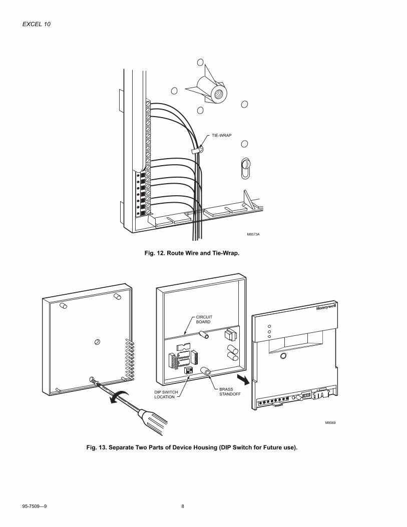
� Route wires and tie-wrap (Refer to Fig. 12).� All wiring to the Q7750A is supervised, except as
noted.� All circuits are power limited except for AC power
circuits, relay contacts and other circuits as noted.� All field wiring terminals accept 24 AWG to 14
AWG (0.25 sq mm to 2 sq mm) conductors, except as noted.
C-Bus Wiring1. Wire the C-Bus using cable (See Table 1).2. Connect the C-Bus cable by attaching the shield to
terminal 18, the positive lead to terminal 16 and the negative lead to terminal 17 according to job drawings(Refer to Fig. 10).
Power WiringInput Power: 24 Vac, 50/60 Hz.
1. Wire 24 Vac power using the heaviest gauge UL level IV or plenum rated UL level IV wire available, up to 14 AWG (2 sq mm) with a minimum of 18 AWG (1 sq mm) wire. For nonplenum, open areas, run cables exposed (or in conduit if required; see the following NOTES).
NOTES:� The Q7750A Excel 10 Zone Manager must have
a dedicated transformer/power source. Do not power any accessories with the Q7750A Excel 10 Zone Manager transformer/power source.
� Keep the transformer/power source as close as possible to the Q7750A Excel 10 Zone Manager so the power wiring will be as short as possible; the maximum length is 6 ft. 6 in. (2 m).
� (US only) When using a 24 Vac transformer larger than 100 VA, Class II power requirements will be exceeded and the power wiring must be enclosed in conduit.
CAUTIONElectrical Shock Hazard.Power Supply can shock.
Make certain no line power is applied to the transformer/power source to prevent device from being attached with power on.
Mounting base power must remain off until installation and wiring is checked by a control system representative.
2. Connect 24 Vac secondary side of the transformer/power source to terminals 1 and 2 on the mounting base according to job drawings (Refer to Fig. 10).
E-Bus Wiring1. Wire the E-Bus using Level IV 22 AWG (Belden part
number 9D220150) or plenum-rated level IV 22 AWG (Belden part number 9H2201504) nonshielded, twisted pair, solid conductor wire, as the recommended wire.
NOTE: When possible, use Honeywell AK3781, AK3782, AK3791, or AK3792 cable (US part numbers).
Table 1. C-Bus Cable Types.
2. Connect the E-Bus wire by attaching one lead to termi-nal 5 and the other lead to terminal 6 according to job drawings (Refer to Fig. 9).
IMPORTANTFor 2000-series devices the E-Bus must be wound one turn through a ferrite cylinder (supplied with the device) a maximum of 7/8 in. (20 mm) from the housing (See Fig. 10).
NOTES:� The E-Bus is insensitive to polarity, eliminating
installation errors due to miswiring.
� To minimize EMI noise, do not run Triac output wires in the same conduit as the input wires or the E-Bus communications loop.
� Unswitched 24 Vac power wiring can be run in the same conduit as the E-Bus cable.
3. For a 2000-series device there are internal termination circuits for both a singly-terminated network topology (jumper between terminals 4 and 5 and between terminals 6 and 7) and for a doubly-terminated bus topology (jumper between terminals 3 and 5 and between terminals 6 and 8) (See Fig. 11).
Maximum Baud Rate Cable Type Description Remarks76.8K JY (St) Y 2x2x0.8 Shielded, twisted pair �
AK3702 Unshielded, twisted pair U.S. onlyAK3740A Shielded U.S. only
921.6K Belden 9842 Twisted pair �Belden 9841 Shielded U.S. onlyAK3702 Unshielded, twisted pair U.S. onlyAK3740A Shielded U.S. only

EXCEL 10
95-7509�9 6
Fig. 10. Wiring Connections (1000-Series E-Bus Details).
4. If a XDM506 modem submodule is being used, attach the modem wiring to the appropriate terminals (9 through 18) on the mounting base (See Figures 10 and 11).
Fig. 11. 2000-Series E-Bus Details.
After wiring is routed, insert the tie-wraps into the holes located near the center of the mounting base (Refer to Fig. 12). Route wire and tie-wrap.
M25577
18
17
16
15
14
13
12
11
10
9
8
7
6
5
4
3
2
1
18
17
16
15
14
13
12
11
10
9
MODEM SHIELD
TXD
FAST BLOW1 AMP FUSE
14507287POWER MODULE
RXD
RI
DCD
DTR
SIGNAL GROUND
DSR
CTS
RTS
24 VAC
24 VAC 24 VAC
EOL
EOL
INTERNALTERMINATIONNETWORK
INTERNALTERMINATIONNETWORK
C-BUS +
C-BUS –
SHIELD
E-BUS
C-BUS
115 VAC
E-BUSE-BUS
115/24 VAC50 VA TRANSFORMER
ON/OFFPOWERSWITCH(OPTIONAL)
FIELD INSTALLED JUMPERS1
1
1
POWER MODULE SOWN FOR U.S. APPLICATIONS ONLY.2
2
3
3
NOT SUPERVISED.
M20109
18
17
16
15
14
13
12
11
10
9
8
7
6
5
4
3
2
1
DOUBLY-TERMINATED EOL
SINGLY-TERMINATED EOL
DOUBLY-TERMINATED EOL
SINGLY-TERMINATED EOL
E-BUS
E-BUSE-BUS
FIELD INSTALLED JUMPERS SHOWN FOR SINGLY-TERMINATEDNETWORKS. JUMPERS FOR DEVICES WITH DOUBLY-TERMINATEDNETWORKS ARE PLACED BETWEEN TERMINALS 3 AND 5 AND BETWEEN TERMINALS 6 AND 8 (SHOWN DOTTED IN SCHEMATIC).
1
1
1
FERRIT RING LOCATED 7/8 IN. (20 MM) MAXIMUM FROM HOUSING.2
2

EXCEL 10
7 95-7509�9
Table 2. Connector Terminal Specifications.
a SIG=Signal, DC=Direct Current.b All voltages are FWR.
Install Electronic Components
CAUTIONEquipment Damage HazardExcessive static can burn out equipment.
Observe proper anti-static material handling practices when installing or servicing PC parts and related components.
Observe proper equipment and body grounding practices.
Discharge static electricity from your body before handling parts.
Complete the Installation1. Before mounting the Q7750A Zone Manager, turn over
the device housing and remove the Phillips screw located at the bottom (remove brass screw/grommet, battery and shipping tab).
2. Separate the two parts of the device housing (Refer to Fig. 13).
NOTE: There is a brass standoff located on the bottom between the circuit board and the top of the device housing. (This connects the shielding between the two parts of the device housing.)
Connector Terminal
Signal Type Input/Output
Voltage Typea
Maximum Voltageb
Maximum Current
Maximum Frequency
Maximum Line
ImpedanceB-Port B Output TXD ±12V ±8 mA 9600 baud 100 ohms
B Input RXD ±20 mAGND � � � � � �
C-Bus 1 C+ Input/Output SIG ±5V 1 mA/180 mA 921.6 baud 100 ohms2 C-3S Shield � � � � � �
E-Bus 1 E+ Input/Output SIG ±5V 1 mA 1.25 mbs2 E-3S Shield � � � � � �
Modem 9 RTS Output DC ±12V ±8 mA � 100 ohms10 CTS Input ±12 mA � �11 DSR � 100 ohms12 GND � � � �13 DTR ±12V ±12 mA � 100 ohms14 DCD �15 RI �16 RXD SIG �17 TXD �18 M Shield � � � � � �
EXCEL 10
95-7509�9 8
Fig. 12. Route Wire and Tie-Wrap.
Fig. 13. Separate Two Parts of Device Housing (DIP Switch for Future use).
M8573A
TIE-WRAP
M8569
BRASSSTANDOFFDIP SWITCH
LOCATION
CIRCUIT BOARD

EXCEL 10
9 95-7509�9
3. Attach the XD505A or the XD508 C-Bus communications submodule or the XDM506 modem submodule, (ordered with the Q7750A) to the male and female connectors on the device circuit board.
CAUTIONEquipment Damage Hazard.Connection misalignment can cause damage to the C-Bus submodule.
C-Bus submodule connectors are not keyed; make sure that the male and female connections are not misaligned.
4. Press firmly down on the submodule (See Fig. 14).5. Reassemble the device housing by connecting the two
parts of the device housing and replacing the brass screw/grommet, battery and shipping tab.
6. Verify the integrity of all the mounting base wiring.
Fig. 14. Attach Submodule, Reassemble Device Housing.
Secure Housing Assembly to Mounting Base1. After all mounting base wiring is checked, carefully align
the device housing over the mounting base. 2. Push firmly on the housing device to secure it to the
mounting base. 3. Tighten the brass screw (See Fig. 15).
Fig. 15. Attach Device Housing to Mounting Base.
Install BatteryIncluded with the device is a 3V Lithium battery, CR 1/2 AA, VARTA number 6127 or equivalent. This battery, when new, provides one month backup of RAM and the Real Time Clock.
NOTES:� When shipped from the factory, the battery has a
shipping tab between the battery positive (+) terminal and the device terminal. Remove the shipping tab during commissioning of the device. (Check and observe the polarity marked on the housing and the battery; reverse if necessary)(See Fig. 16).
� When the battery is removed during a loss of input power, RAM data is lost and the device must be re-downloaded.
Fig. 16. Remove Battery Shipping Tab During Device Commissioning.
SUBMODULE M8574
M8570
M8565

EXCEL 10
95-7509�9 10
CHECKOUT
Step 1. Wiring ConnectionsInspect all wiring connections at the Q7750A terminals and verify compliance with job drawings. If any wiring changes are required, first be sure to remove power from the controller before starting work. Pay particular attention to:� 24 Vac power connections. Verify that when there are
multiple Q7750A Excel 10 Zone Managers, each one has a dedicated transformer/power source, with the transformer secondary connected to terminals 1 and 2 on the mounting base, according to job drawings (Refer to Figures 10and 11).
� E-Bus wires. Be sure that the E-Bus wires are attached to terminals 5 and 6 according to job drawings. If the Q7750A device is located at one end of the E-Bus network, check to determine if the termination network was activated by placing two wires (optional jumpers) between the following terminal pairs (Refer to Fig. 11):
4,5 and 6,7 (singly-terminated network)3,5 and 6,8 (doubly-terminated network)
� C-Bus shield. Be sure that the C-Bus shield is attached to terminal 18, the positive lead to terminal 16, and the negative lead to terminal 17 according to job drawings (Refer to Figures 10 and 11).
� Check to see that the ferrite ring is in place on the E-Bus (Refer to Fig. 11).
All wiring must comply with applicable electrical codes and ordinances. Refer to job or manufacturer drawings for details..
Fig. 17. Q7750A Excel 10 Zone Manager LED Locations.
Table 3. Q7750A Excel 10 Zone Manager LED Status Information.
aLEDs 3 through 7 flicker with the frequency of data being transmitted or received (See NOTE).
M8560
B-PORT RECEIVE
B-PORT SEND
ERRORE-BUS OPERATION
B-PORT CONNECTION
BATTERY
RESET BUTTON5V
CONTR.
C-BUS RECEIVE
C-BUS SEND
EXCEL 10 ZONE MANAGERASSEMBLY (SHOWNWITHOUT FRONT COVER)
MOUNTING BASE
LED Explanation Color LED Function if On LED Function if Off1 5V (POWER) Green Power O.n Power Off.2 Contr. (RUN) Green Software is running,
watchdog is triggered.
Watchdog locked, software not working.
3 B-PORT (send) Yellow Q7750A sends data on RS232 porta.
No communication.
4 B-PORT (receive) Yellow Data is sent to Q7750A on the RS232 porta.
No communication.
5 C-Bus (send) Yellow Q7750A sends data on the C-Busa.
No data sent on the C-Bus.
6 C-Bus (receive) Yellow Q7750A receives data on the C-Busa.
No data received from the C-Bus.
7 E-Bus Yellow E-Bus network activitya (see NOTE).
No E-Bus network activity.
8 Error Red Blinking: not configured, application loaded.On: no configured, no application.
Valid configuration.

EXCEL 10
11 95-7509�9
Step 2. Initial Power UpApply power to the Q7750A. When the Q7750A receives power, the LEDs should appear in normal (uncommissioned and not downloaded) condition (Refer to Table 2).
NOTE: LED 7 is used to display E-Bus network activity. In 1000-series devices it flickers with data being transmitted or received, but in 2000-series devices it flickers only with data being received.
If the status is not correct, push the reset button. Verify that the LED status is correct before proceeding.
IMPORTANTThe CPU reset button deletes the application program in the CPU (stored in RAM). If the reset button is pushed when the CPU contains an application, the device must be re-downloaded.
Step 3. CommissioningThe Zone Manager CPU can be commissioned (given a C-Bus address) using an operator terminal such as the XI581 (on the PC that has the XI584 software and/or CARE installed). This operation is performed the same as for other C-Bus controllers. The following steps describe the most common procedure using the PC to commission the CPU just before downloading from the XI584.
As for other C-Bus controllers, commissioning is required only after an initial power-up or if the CPU reset button was pushed. The following steps assume the Zone Manager Plant and Controller are configured in CARE (see Data File Setup section):
1. Connect the PC COM port to the Zone Manager B-port using the XW565 (or XW566) prefabricated cable.
2. Start XI584. Sign on and run XI581. Assign the controller number using the procedure for C-Bus devices (see the XI584 User's Guide, form 74-3555).
3. Select Continue again, and select Request Download. The operator terminal should then display. Please Execute Download.
4. Select Utilities and drop down to the item File Transfer/Download. Click on All and initiate the Download. Commissioning is complete.
The B-port Transmit and B-port Receive LEDs on the Zone Manager should start blinking rapidly, indicating communication between the PC and the Zone Manager.
Any Download errors or connecting problems appear in the Download Results list box. A loss of communication with the B-port during downloading generates an alarm after three minutes. Press Enter and try again to download.
If there is trouble establishing communication between the PC and the Zone Manager, check the following items:� XW565 cable connections.� XW565 cable connection is to the same PC COM port as
selected in the CARE Download System Settings menu.
IMPORTANTCarefully watch all C-Bus alarm activity following a download. Follow up as necessary on all problem alarms.
Fig. 18. Connect Operating Device.
Close CoverPut the device cover back on (See Fig. 19).
Fig. 19. Close Cover.
DATA FILE SETUPGenerate the CARE data file for the Zone Manager/RIO/Excel 10 VAV2 controllers. This data file has a mix of hardware points for the necessary inputs and outputs to control fans, dampers and other equipment. In addition to the inputs and outputs, a custom control program is written to control the outputs per the sequence. It also resets the program once the data from the operator interface indicates a normal condition for the new dedicated smoke control equipment. Wire conditions must be programmed to provide annunciation of trouble conditions. Also required for a dedicated application is a weekly time program to test control points, fans and dampers by exercising the equipment and verifying feedback automatically during low building activity periods.
M8558
M8559

EXCEL 10
95-7509�9 12
PANEL RESETWhen in Smoke Control Mode, panel reset is accomplished by resetting the initiating panel contact circuit or by the separate initiating/reset switch on the FSCS panel.
Field Parameters�Minimum/Maximum Rating
W7751B,D,F,H,RIOTriac Outputs: 24 Vac at 550 mA, steady state, pilot duty.Device:.24A maximum at 25V.Digital Inputs: 4.8± 0.8 Vdc, 9 mA ±1 mA.E-Bus: Not readable.A max. of 5 triac outputs may be on at one time.

EXCEL 10
13 95-7509�9
SMOKE CONTROL CONFIGURATION
Fig. 20. Smoke Control Configuration.
M25400
UL LISTED FIRE ALARMCONTROL UNITALARM INPUT
14505068AUDIBLE
ANNUNCIATOR
FIREFIGHTERSSMOKE CONTROLPANEL (FSCS)
XL 10 VAV2Q7750ARIO
STATUS DO
DOXL 10VAV2
AIRFLOW SENSOR
DAMPER
DO
AO
STATUS CONTROL
LONBUS
LONBUS
SMOKE CONTROL CONFIURATION
DI
16
6
7 10 13
12 9
4
5
3
2
11
14
1
8
15
15
14 SUPPLYFAN
SUPPLYFAN
Q77
50A
ZON
E M
AN
AG
ER
W77
51 B
,D,F
,H
RIO
W77
61
LOCATE AND CONFIGURE PER NFPA 92A. UL LISTED ANNUNCIATOR/FSCS PANEL SWITCHES HAVE A MIN RATING OF 24V,1/10 AMP AND LAMPS/LEDS HAVE A RATING OF 24V, LIMITED TO 50 mA. LOCATE WITHIN SAME ROOM AND WITHIN 20 FTIN CONDUIT OF RIO.
LOCATE TO MINIMIZE CONTROL WIRING AND PIPING. AVOID RUNNING WIRES OR PIPING THROUGH AREAS THAT HAVE A HIGH FIRE RISK.
LOCATE PER UL 555S.
LOCATE SEPARATE FROM AND BELOW ALL BUILDING EXHAUST FANS AND UPSTREAM FROM ANY PREVAILING WINDS.
EXHAUST TO OUTSIDE OF BUILDING. FREEZE CONTROL SENSING LIMIT MUST BE SET LESS THAN 32°F (0°C) WHEN IN SMOKE CONTROL MODE.
SMOKE CONFIGURATION IS ONLY VALID WITH THE EXCEL 10 VAV AND EXCEL 10 REMOTE I/O THAT HAVE UUKL LISTING. UUKL LISTED EXCEL 10 CONTROLLERS ARE W7751B2010, W7751D2016, W7751F2011, W7751H2025 AND W7761A2010.
LOCATE UL LISTED DAMPER PRESSURE/POSITION INDICATOR PER DAMPER INSTALLATION INSTRUCTIONS.
SMOKE CONTROL MUST BE INITIATED BY A LISTED FIRE ALARM CONTROL UNIT OR IN ZONE AUTOMATIC ALARM DEVICES AND NOT DEVICES LOCATED OUTSIDE OF THE SMOKE CONTROL ZONE. INTERCONNECTING WIRING MUST BE WITHIN 20 FT (6M) AND IN CONDUIT.
REFER TO NFPA 92A AND UL 864.
VERIFY AC VOLTAGE SOURCE CONNECTED TO INSIDE OF MAIN LINE VOLTAGE TERMINAL BLOCK IS FROM A UL 1481 LISTED UNINTERRUPTIBLE POWER SUPPLY. THE MAIN LINE VOLTAGE TERMINAL BLOCK MAXIMUM CURRENT DRAW IS 0.5 AMPS. USE 14502412-011 AC TRANSIENT PROTECTION.
ALL EXTERNAL FIELD WIRING MUST BE LIMITED TO 3277 FT (999M) AND BE TERMINATED TO 14506944-001 TRANSIENT PROTECTOR (35V, 290 mA MAX.) EXCEPT C-BUS FIELD WIRING COMMUNICATING AT 1MHZ WHICH USES 14502412-010 TRANSIENT PROTECTOR (19V, 500 mA) WHEN FIELD WIRING LEAVES THE ZONE.
REFER TO JOB DRAWING FOR DEVICE INSTALLATION.
USE 14507287-001 AND -007 CLASS II POWER SUPPLIES, MAX. LOADING 100 VA.
INSTALL IN SIGNAL SYSTEM ENCLOSURE CABINET.
REFER TO ZONE MANAGER INSTALLATION SECTION FOR LON BUS (E-BUS) CONNECTIONS AND DEVICE INSTALLATION.
PER NFPA 92A THIS EQUIPMENT IS UTILIZED AS NON-DEDICATED SMOKE CONTROL EQUIPMENT. STATUS OF AIRFLOW CONTROL MUST BE PROVIDED VIA THE AIRFLOW SENSOR INPUT.
1
2
3
4
5
6
7
8
9
11
10
12
13
14
15
16

EXCEL 10
95-7509�9 14
Fig. 21. Typical Power Limited Circuit for Excel ZM, RIO, or Excel 10 Panel Mounted Devices.
M25578
14507287-001 THROUGH -003 POWER MODULE ACCESSORY 24V AC OUTPUT (RATED 2A) MUST BE WIRED IN ACCORDANCE WITH NFPA 70, ARTICLE 725 WHEN ROUTED WITHIN THE CABINET OR ADJACENT CABINETS AND ALSO FOR EXTERNAL FIELD WIRING.
14507287-001 OR -007 CONTROL POWER MODULE 24VAC OUTPUT IS INHERENTLY POWER LIMITED. THUS, ALL SOURCED POWER FROM THE EXCEL ZONE MANAGER, RI0, EXCEL 10 PANEL MOUNTED DEVICES ARE POWER LIMITED. ALL FIELD WIRING FROM THESE CONTROLLERS MEET NFPA 70, ARTICLE725 POWER LIMITED CLASS II REQUIREMENTS. IF A SEPARATE AUXILIARY "POWER LIMITED" 24V AC POWER SOURCE IS REQUIRED, USE A CONTROL POWER MODULE (14507287-001 OR -007).
DEVICES MUST BE INSTALLED IN AREAS AS SHOWN.
ALL CABLE MUST BE ROUTED AS SHOWN.
ALL INTERNAL POWER LIMITED WIRING MUST BE SEPARATED BY 1/4 IN. (6MM) OR BARRIER FROM NON-POWER LIMITED WIRE. EXCESSWIRING MUST BE CUT, TRIMMED AND DRESSEDPROPERLY TO ENSURE PROPER CLEARENCESARE MAINTAINED.
1
3
4
2
RELAY
POWER LIMITED
ACCESSORY 24VAC
14507287-001 OR -007120VAC 14507287-007
ZM, R10
OR EXCEL 10
ZM, R10
OR EXCEL 10
DIGITAL
OUTPUT
POWERLIMITED
POWERLIMITED
NONPOWERLIMITED
NONPOWERLIMITED
NONPOWERLIMITED
4
12
2CONTROL
24VAC
6944
6944
6944
6944

EXCEL 10
15 95-7509�9
Step 4. Troubleshooting.
OPERATIONThe Q7750A controllers have LED indicators that are used to show controller activity. Their function is identified on the controller nomenclature.
Maintenance ProceduresThe system must be maintained in accordance with the system documentation and procedures and practices contained in applicable NFPA and UL standards. The internal memory in this series of controllers is supported by a Varta 6127 CR 1/2 AA 3V lithium battery (not rechargeable). When the battery requires replacement, a low battery condition is indicated on the controller and sent to the MMI and central monitoring station. Replace when needed with the same battery type. For service, contact your local Honeywell Home & Building Control office as listed in the phone book, or contact a regional office as shown at the end of this document.
Problem Description Solution5V (Power) LED not on. No power to the Zone Manager. Apply power or verify the power wiring (voltage must be 20-
30V), check fuses and output from power module or transformer number.
Run LED is on. Zone Manager not operating. Software failure, do the following:� Power the Zone Manager down, then up.� Push the CPU reset button.� If the motherboard EPROM has been removed, it may
have been incorrectly re-installed.� Commission the Zone Manager.
C-Bus Transmit LED not flashing, C-Bus Receive LED not flashing.
No C-Bus connection or no other C-Bus devices active on the bus.
� Disassemble the Zone Manager and check the C-Bus communication daughterboard (XD 505, XD 508) mounted on the Zone Manager motherboard and reseat it.
� Verify the C-Bus wiring terminations, polarity.C-Bus Transmit LED not flashing,C-Bus Receive LED not flashing.
Zone Manager transmitting on the C-Bus, but not receiving.
� Disassemble the Zone Manager and check the C-Bus communication daughterboard (XD 505, XD 508) mounted on the Zone Manager motherboard and reseat it.
� Verify the C-Bus wiring terminations, polarity.C-Bus Transmit LED not flashing,C-Bus Receive LED not flashing.
Zone Manager receiving on the C-Bus, but not transmitting.
� Commission the Zone Manager.� Verify C-Bus wiring terminations, polarity.
B-port Transmit LED not flashing,B-port Receive LED not flashing.
These only flash when an operator interface is communicating with the B-port.
� Cycle power.� Reconnect the operator interface.� Try the operator interface on another controller.
E-Bus LED not flashing. No E-Bus connection or no devices active on the E-Bus.
Disassemble the Zone Manager and verify the E-Bus wiring.
E-Bus LED flashing. Zone Manager transmitting or receiving on the E-Bus, but other devices on the E-Bus not receiving.
� Verify E-Bus wiring.� Commission the Zone Manager.
Error LED on. CPU hardware/firmware failure. Do the following:� Power the Zone Manager down, then up.� Push the CPU reset button.� If the motherboard EPROM has been removed, it may
have been incorrectly re-installed.� Commission the Zone Manager.
Batter Low message on an XBS, XI581, or XI584 Operator Terminal.
Internal test of 3V lithium battery shows low power, possible failure.
Remove and test the battery by putting a 5K ohm (0.24 watt, 5%) resistor across the positive and negative poles. If the voltage is less than 2.5V, replace the battery. Replace with a lithium 3V 100 mA hour, CR 1/2 AA, VARTA 6127 or equivalent.

EXCEL 10
Automation and Control SolutionsHoneywell International Inc. Honeywell Limited-Honeywell Limitée1985 Douglas Drive North 35 Dynamic DriveGolden Valley, MN 55422 Toronto, Ontario M1V 4Z9www.honeywell.com/buildingsolutions
® U.S. Registered Trademark© 2010 Honeywell International Inc.95-7509�9 J.I. Rev. 07-10
Echelon® and LONWORKS® are registered trademark of Echelon Corporation.
Excel 5000� is a trademark of Honeywell International Inc.
Microsoft Windows� is a trademark of Microsoft Corporation.
Tapcon� is a trademark of Illinois Tools Works Inc. Corporation.
Varta� is a trademark of VARTA AKTEINGESELLSCHAFT CORPORATION.