940 - giulietta - fiataftersales.fiat.com/elumdata/en/83/191_giulietta/83_191_giulietta_604... ·...
TRANSCRIPT

OWNER HANDBOOK
ENGLISH
cop lum giulia GB.indd 1cop lum giulia GB.indd 1 11/12/15 10:5811/12/15 10:58
This Owner Handbook illustrates the operating instructions of the car.
Alfa Romeo provides a dedicated section available in electronic format for enthusiasts who want insights, curiosities and detailed information about the features and functions of the car.
ONLINE OWNER HANDBOOK
The symbol appears in the Owner Handbook next to topics for which updates are available.
Go to elum.alfaromeo.com where you will find all the details of the Owner Handbook.
Alternatively, to access this information, go to the Internet website at http://aftersales.fiat.com/elum/.
The eLUM website is free and conveniently allows you to browse the on-board documents of all other models of the Group, among many other things.
Have a nice read and happy motoring!
ALFA ROMEO GENUINE SPARE PARTS AND ACCESSORIES
PERFECT FOR YOUR VEHICLE, RIGHT DOWN TO THE SMALLEST DETAIL
The Alfa Romeo Genuine Spare Parts and Accessories follow the rigid component engineering and manufacturing specifi cations used in the assembly line to meet the technical specifi cations of your new Alfa Romeo and to enhance its style and performance. They undergo strict approval tests and quality controls to ensure they comply with safety and environmental standards.
All of the components on your new Alfa Romeo, from the smallest bulb to the most complex mechanical, electrical and electronic systems, are designed to work in harmony and guarantee you a comfortable and safe drive, in full respect for the environment. The Genuine Accessories fully enhance the style of your new vehicle.
Entrust the experience and quality of Alfa Romeo Dealerships to fi nd the full range of Alfa Romeo Genuine Spare Parts and Accessories.
Find your nearest Dealership on www.alfaromeo.com
retro cop alfa giulia EN.qxp_500 UM ITA 16/12/15 09:26 Pagina 1
Dear Customer,
We would like to congratulate and thank you for choosing an Alfa Romeo.
We have written this handbook to help you get to know all the features of your vehicle and use it in the best possible way.
Here you will find information, advice and important warnings regarding use of your vehicle and how to achieve the best performancefrom the technical features of your Alfa Giulietta.
You are advised to read it right through before taking to the road for the first time, to become familiar with the controls and above allwith those concerning brakes, steering and gearbox; at the same time, you can understand the vehicle behaviour on different roadsurfaces.
This document also provides a description of special features and tips, as well as essential information for the safe driving, care andmaintenance of your Alfa Giulietta over time.
In the attached Warranty Booklet you will also find the description of the Services that Alfa Romeo offers to its customers, theWarranty Certificate and the detail of the terms and conditions for maintaining its validity.
We are sure that these will help you to get in touch with and appreciate your new car and the service provided by the people at AlfaRomeo.
Enjoy reading. Happy motoring!

READTHIS CAREFULLYREFUELLING
Petrol engines: only refuel with unleaded petrol with octane rating (RON) not less than 95 in compliance with the European specification EN228.Diesel engines: refuel only with diesel fuel for motor vehicles conforming to the European specification EN590. The use of other products ormixtures may damage the engine beyond repair and consequently invalidate the warranty, due to the damage caused. LPG engines: refuel only withLPG for motor vehicles conforming to the European specification EN589. The use of other products or mixtures may damage the engine beyondrepair and consequently invalidate the warranty, due to the damage caused.
STARTINGTHE ENGINEPetrol engines: make sure that the handbrake is engaged; set the gear lever to neutral; fully depress the clutch pedal without pressing theaccelerator, then turn the ignition key to AVV and release it as soon as the engine has started.Diesel engines: turn the ignition key to MAR and waitfor the icon and warning light to switch off. Then turn the ignition key to AVV and release it as soon as the engine has started.
PARKING ON FLAMMABLEMATERIALThe catalytic converter develops high temperatures during operation. Do not park the car on grass, dry leaves, pine needles or other flammablematerial: fire hazard.
RESPECTINGTHE ENVIRONMENTThe vehicle is fitted with a system that carries out a continuous diagnosis of the emission-related components in order to help protect theenvironment.
ELECTRICAL ACCESSORIESIf, after buying the car, you decide to add electrical accessories (with the risk of gradually draining the battery), contact an Alfa Romeo Dealership.They will calculate the overall electrical requirement and check that the car’s electrical system can support the required load.
SCHEDULED SERVICINGCorrect maintenance of the car is essential for ensuring that it maintains its performance and its safety features, its environmental friendliness andlow running costs for a long time to come.
THE OWNER HANDBOOK CONTAINS…important information, advice and warnings for correct use, driving safety and maintenance of the car over time. Special attention must be paid tothe symbols (personal safety) (environmental protection) (car integrity).

USEOFTHEOWNERHANDBOOKEach time direction instructions (left/right or forwards/backwards) about the vehicle are given, these must be understood asregarding an occupant in the driver's seat. Special cases not complying with this rule will be specified as appropriate in the text.The figures in the Owner Handbook are provided by way of example only: this might imply that some details of the image do notcorrespond to the actual arrangement of your vehicle. In addition, the Handbook has been conceived considering vehicles withsteering wheel on the left side; it is therefore possible that on vehicles with steering wheel on the right side, the position orconstruction of some controls is not exactly mirror-like with respect to the figure.To identify the chapter with the information needed you can consult the index at the end of this Owner Handbook.Chapters can be rapidly identified with dedicated graphic tabs, at the side of each odd page. A few pages further there is a key forgetting to know the chapter order and the relevant symbols in the tabs. There is in any case a textual indication of the current chapterat the side of each even page.

PRECAUTIONS ANDWARNINGSWhile reading this Owner Handbook you will find a series ofWARNINGS to prevent procedures that could damage your vehicle.There are alsoPRECAUTIONS that must be carefully followed to prevent incorrect use of the components of the vehicle, which couldcause accidents or injuries.Therefore, allWARNINGS andPRECAUTIONSmust always be followed carefully.WARNINGS andPRECAUTIONS are recalled in the text with the following symbols:
personal safety;
vehicle safety;
environmental protection.
NOTE These symbols, when necessary, are indicated besides the title or at the end of the line and are followed by a number. Thatnumber recalls the corresponding warning at the end of the relevant section.
IMPORTANT
This Owner Handbook describes all Alfa Giulietta versions. Options, equipment dedicated to specific markets or versions arenot explicitly indicated in the text: as a consequence, you should only consider the information which is related to the trimlevel, engine and version that you have purchased. Any content introduced throughout the production of the model, outside theexplicit request of options at the time of purchase, will be identified with the wording (for versions/markets, where provided).
All data contained in this publication are intended to help you use your vehicle in the best possible way. FCA Italy S.p.A. aims ata constant improvement of the vehicles produced. For this reason it reserves the right to make changes to the model describedfor technical and/or commercial reasons.
For further information, contact an Alfa Romeo Dealership.
VEHICLE CHANGES / ALTERATIONS
IMPORTANT Any change or alteration of the vehicle might seriously affect its safety and road holding, thus causing accidents, inwhich the occupants could even be fatally injured.
4
GETTINGTOKNOWYOURCAR
KNOWINGTHE INSTRUMENTPANEL
SAFETY
STARTINGANDDRIVING
IN AN EMERGENCY
SERVICINGANDMAINTENANCE
TECHNICAL SPECIFICATIONS
MULTIMEDIA
INDEX


In-depth knowledge of your new car starts here.The booklet that you are reading simply and directly explains how
it is made and how it works.That’s why we advise you to read it seated comfortably on board,
so that you can see what is described here for yourself.
GETTINGTOKNOWYOURCARTHE KEYS . . . . . . . . . . . . . . . . . . . . . . . . . . . . . . . . . . . .8IGNITION DEVICE . . . . . . . . . . . . . . . . . . . . . . . . . . . . . . .9ALFA ROMEO CODE SYSTEM . . . . . . . . . . . . . . . . . . . . . . .10ALARM SYSTEM. . . . . . . . . . . . . . . . . . . . . . . . . . . . . . .11DOORS. . . . . . . . . . . . . . . . . . . . . . . . . . . . . . . . . . . . .11SEATS . . . . . . . . . . . . . . . . . . . . . . . . . . . . . . . . . . . . .13HEADRESTS . . . . . . . . . . . . . . . . . . . . . . . . . . . . . . . . .15STEERING WHEEL. . . . . . . . . . . . . . . . . . . . . . . . . . . . . .15REAR VIEW MIRRORS . . . . . . . . . . . . . . . . . . . . . . . . . . .16EXTERNAL LIGHTS . . . . . . . . . . . . . . . . . . . . . . . . . . . . .17INTERIOR LIGHTS . . . . . . . . . . . . . . . . . . . . . . . . . . . . . .20WINDSCREEN/REAR WINDOW WIPER . . . . . . . . . . . . . . . . .20CLIMATE CONTROL . . . . . . . . . . . . . . . . . . . . . . . . . . . . .22ELECTRIC WINDOWS . . . . . . . . . . . . . . . . . . . . . . . . . . . .26ELECTRIC SUNROOF . . . . . . . . . . . . . . . . . . . . . . . . . . . .27ENGINE BONNET . . . . . . . . . . . . . . . . . . . . . . . . . . . . . .29BOOT . . . . . . . . . . . . . . . . . . . . . . . . . . . . . . . . . . . . . .30HEADLIGHTS . . . . . . . . . . . . . . . . . . . . . . . . . . . . . . . . .31Alfa DNA SYSTEM (Car dynamic control system) . . . . . . . . . . .31VERSION WITH LPG SYSTEM . . . . . . . . . . . . . . . . . . . . . . .32

THEKEYS
MECHANICALKEY
Operation
The metal insert 1 fig. 1 operates:the ignition switch;the door lock.
KEYWITHREMOTE CONTROL(for versions/markets, where provided)
Operation
The metal insert 1 fig. 2 operates:the ignition switch;the door lock.
Press button 2 to open/close the metalinsert. 1)
Door and luggage compartment locking
Brief press of button : locks doors,switches off internal roof lights withsingle flash of direction indicators (forversions/markets, where provided).
Press the button to open theluggage compartment remotely. Thedirection indicators will flash twice toindicate that the luggage compartmenthas been opened.
REQUESTINGADDITIONAL REMOTECONTROLS
The system can recognise up to 8 keyswith incorporated remote control. If youneed to request a new remote control,contact an Alfa Romeo Dealership, takingthe CODE Card (for versions/markets,where provided), an identity documentand documents proving ownership of thecar with you.
REPLACINGTHEBATTERY INTHEKEYWITHREMOTE CONTROL
Procedure
1)
press button 1 fig. 3 and move themetal insert 2 to opening position; turnscrew 4 to using a fine bitscrewdriver;
remove battery compartment 5 andreplace battery 3, respecting the polarity;reinsert compartment 5 in the key andsecure it by turning screw 4 to .
SAFE LOCKDEVICE(for versions/markets, where provided)
This safety device inhibits the operationof the interior door handles and the doorlocking/unlocking button. We recommendthat you activate this device each timeyou park your car.
1 A0K0545C
2 A0K0546C
3 A0K0547C
8
GE
TT
ING
TOK
NO
WY
OU
RC
AR

Activating the device
The device is enabled on all the doors bypressing the button on the key twicequickly. Device activation is indicated by3 flashes of the direction indicators and aflash of the LED on the button on thedashboard. The device does not come onif one or more doors is not properly shut.
Deactivating the device
The device disengages automatically:the key insert is turned to opening
position in the driver side door;by pressing the button on the key;by turning the ignition key to the MAR
position.
IMPORTANT Once the safe lock systemis engaged, it is impossible to open thedoors from inside the car. Therefore,before getting out of the car check thatthere is no one left on board. If theremote control battery is flat, the devicecan only be deactivated by using themetal insert in one of the door locks.
WARNING
1)Press button 2 only with the key awayfrom your body, especially your eyes andfromobjectswhich could get damaged (e.g.your clothes). Do not leave the keyunattended to avoid the button beingaccidentally pressedwhile it is beinghandled, e.g. by a child.
IMPORTANT
1)Used batteriesmay be harmful to theenvironment if not disposed of correctly.Theymust be disposed of as specified by lawin the special containers or taken to anAlfaRomeoDealership, whichwill take care oftheir disposal.
IGNITIONDEVICE
The key can be turned to three differentpositions fig. 4:
STOP: engine off, key can be removed,steering column locked. Some electricaldevices (e.g. radio, central door lockingsystem, alarm, etc.) are enabled;
MAR: driving position. All electricaldevices are enabled;
AVV: engine starting.
The ignition device is fitted with a safetysystem that requires the ignition key tobe turned back to STOP if the enginedoes not start, before the startingoperation can be repeated. 2) 3)
STEERING LOCK
Activation
When the key is at STOP, remove the keyand turn the steering wheel until it locks.
4 A0K0362C
9

Deactivation
Move the steering wheel slightly and turnthe ignition key to MAR. 4) 5)
WARNING
2) If the ignition device has been tamperedwith (e.g. an attempted theft), have itchecked over by the Alfa RomeoDealershipbefore driving again.3)Always remove the keywhen you leaveyour car to prevent someone fromaccidentally operating the controls.Remember to engage the handbrake.Engage first gear if the vehicle is parkeduphill or reverse if the vehicle is parkeddownhill. Never leave children unattended inthe vehicle.4) It is absolutely forbidden to carry out anyafter-market operation involving steeringsystemor steering columnmodifications(e.g. installation of anti-theft device) thatcould adversely affect performance andsafety, invalidate thewarranty and alsoresult in the car notmeeting type-approvalrequirements.5)Never remove the keywhile the car ismoving. The steeringwheel willautomatically lock as soon as it is turned.This holds true for cars being towed aswell.
ALFAROMEOCODESYSTEM
The Alfa Romeo Code preventsunauthorised use of the vehicle, disablingengine starting. 1)
Operation
Each time the car is started by turningthe ignition key to MAR, the Alfa RomeoCODE system control unit sends anacknowledgement code to thePowertrain Control Module to deactivatethe inhibitor.
The code is sent only if the Alfa RomeoCODE system control unit has recognisedthe code transmitted by the key.
Each time the ignition key is turned toSTOP, the Alfa Romeo CODE systemdeactivates the functions of thePowertrain Control Module.
Irregular operation
If, during starting, the code is notcorrectly recognised, the icon
appears on the instrument panel.
In this case, turn the key to STOP andthen to MAR-ON; if it is still locked, tryagain with the other keys that come withthe car. If it is still not possible to startthe engine, contact an Alfa RomeoDealership.
Activation of warning light whiledriving
If the icon appears on the display,this means that the system is running aself-diagnosis (for example due to avoltage drop).
If the icon continues to bedisplayed, contact an Alfa RomeoDealership.
IMPORTANT
1) The electronic components inside the keymay be damaged if the key is subjected tostrong shocks. In order to ensure completeefficiency of the electronic devices inside thekey, it should never be exposed to directsunlight.
10
GE
TT
ING
TOK
NO
WY
OU
RC
AR

ALARMSYSTEM
(for versions/markets, where provided)
ALARMACTIVATION
Activation of the alarm triggers theacoustic warning and the directionindicators.
IMPORTANT The alarm is adapted by theManufacturer to meet the requirementsof the various countries where thevehicle is marketed.
SWITCHINGONTHEALARM
With the doors, bonnet and tailgateclosed and the ignition key either turnedto STOP or removed, point the key withremote control towards the car and pressand release the button .
Except on some versions for specificmarkets, the system produces a visualand acoustic warning and enables doorlocking.
ALARMSELF-ACTIVATION(for versions/markets, where provided)
If the alarm has not been activated usingthe remote control, approximately30 seconds after the key is turned to theSTOP position and the last time one ofthe doors or tailgate was opened andreclosed, the alarm is activatedautomatically.
This condition is indicated by theintermittent illumination of the LED onthe alarm deactivation button on the rooflight and by the activation indicationsdescribed previously.
To deactivate the alarm, press the buttonon the remote control.
Alarm self-activation also occurs whenthe doors are closed by turning the metalinsert of the key in the driver door lock. Ifthe alarm is self-activated, the doors willnot be locked.
TURNINGTHEALARMOFF
IMPORTANT Activating the centralopening using the key's metal insert doesnot turn the alarm off.
DOORS
DOORCENTRAL LOCKING/UNLOCKING
Locking from the outside
With the doors closed, press thebutton on the key or fit and then turn
the metal insert (located inside the key)in the driver side door lock.
The door locking function is operated:with all the doors closed;with all the doors closed and boot
open.
Door unlocking from the outside
Press the button on the key or turn themetal insert (located inside the key) inthe driver side door lock.
Door locking/unlocking from the inside
Press the button on the dashboard.
IMPORTANT With central locking active,pulling the internal opening lever of thepassenger side door unlocks the dooritself. Pulling the internal opening leverof the driver side door activates centralunlocking.
IMPORTANT The rear doors cannot beopened from the inside when the childlock device is engaged.
In the absence of electrical power supply(e.g. blown fuse, battery disconnected,etc.) it is still possible to lock the doorsmanually.
11

CHILD SAFETYDEVICEThis system prevents the rear doors frombeing opened from the inside.
This device 1 fig. 5 can be engaged onlywith the doors open:
position A - device engaged (doorlocked);
position B - device not engaged (doormay be opened from the inside).
The device remains engaged even if thedoors are electrically unlocked. 2) 3)
IMPORTANT The rear doors cannot beopened from the inside when the childlock device is engaged.
EMERGENCYDOOR LOCKINGDEVICE
Front passenger door
The passenger side front door has adevice to lock it when there is noelectrical current.
To lock it, fit the metal insert of the
ignition key into housing 1fig. 6 and moveit upwards.
Rear doors
The rear doors are fitted with anemergency device that allows the doorsto be locked when there is no current.
In this case, proceed as described below:fit the metal insert of the ignition key
into housing 2 fig. 5;turn the key anticlockwise and then
remove it from housing 2 fig. 5.
The door lock knob can be realigned (onlywhen the battery charge has beenrestored) as follows:
by pressing the button on the key;press the door locking/unlocking
button on the dashboard;opening the door by inserting the key
in the front door pawl;operate the internal door handle.
4)
Opening/closing mechanisminitialisation
If the battery is disconnected or theprotection fuse blows, the dooropening/closing mechanism must beinitialised as follows:
close all the doors;press the button on the key or the
button on the dashboard;press the button on the key or the
button on the dashboard.
IMPORTANT
2)Always use this device when carryingchildren.3)After engaging the child lock on both reardoors, check for proper engagement bytrying to open a rear doorwith the internalhandle.4) If the child lock devicewas engaged andthe previously described locking procedurecarried out, operating the internal handlewillnot open the door butwill only realign thedoor lock knobs. To open the door, pull theexternal handle. The door centrallocking/unlocking button is not disabledby the engagement of the emergency lock.
5 A0K0579C
6 A0K0580C
12
GE
TT
ING
TOK
NO
WY
OU
RC
AR

SEATS
FRONTSEATS
Lengthwise adjustment
Lift lever 1 fig. 7 and push the seatforwards or backwards: in the drivingposition, you should be able to rest yourarms on the rim of the steering wheel.
6) 7)
Height adjustment(for versions/markets, where provided)
Move lever 3 fig. 7 up or down until therequired height is reached.
IMPORTANT Carry out the adjustmentwhilst seated in the driver's seat.
Backrest angle adjustment
Turn knob 2 fig. 7 until the requiredposition is reached.
8)
Electric seat heating(for versions/markets, where provided)
With the key turned to MAR, press button1 fig. 8 to switch the function on/off.
When the function is enabled, the LED onthe button turns on.
Electric lumbar adjustment(for versions/markets, where provided)
With the key turned to MAR, press button2 fig. 8 to switch the function on/off.
When the function is enabled, the LED onthe button turns on.
FRONTSEATSWITH ELECTRICADJUSTMENT(for versions/markets, where provided)
The controls for seat adjustment arefig. 9:
Control 1: Driver's seat position memorybuttons
Control 2: Backrest angle and lumbaradjustment.
Multifunction control 3: seat heightadjustment (vertical movement of seat)and back and forward movement of theseat.
IMPORTANT Electric adjustment is onlypossible with the ignition key turned toMAR and for approximately 1 minuteafter turning it to STOP. The seat can bemoved for approximately 3 minutes afteropening or closing the door.
SEATHEATING(for versions/markets, where provided)
With the ignition key at MAR, turn ring 1fig. 10 to switch the function on/off.
7 A0K0366C
8 A0K0213C
9 A0K0214C
13
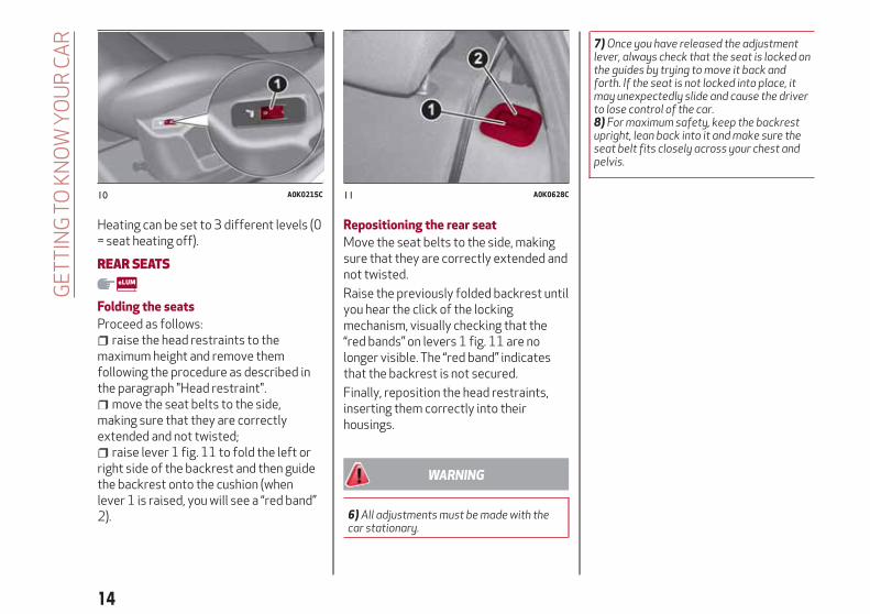
Heating can be set to 3 different levels (0= seat heating off).
REARSEATS
Folding the seats
Proceed as follows:raise the head restraints to the
maximum height and remove themfollowing the procedure as described inthe paragraph "Head restraint".
move the seat belts to the side,making sure that they are correctlyextended and not twisted;
raise lever 1 fig. 11 to fold the left orright side of the backrest and then guidethe backrest onto the cushion (whenlever 1 is raised, you will see a “red band”2).
Repositioning the rear seat
Move the seat belts to the side, makingsure that they are correctly extended andnot twisted.
Raise the previously folded backrest untilyou hear the click of the lockingmechanism, visually checking that the“red bands” on levers 1 fig. 11 are nolonger visible. The “red band” indicatesthat the backrest is not secured.
Finally, reposition the head restraints,inserting them correctly into theirhousings.
WARNING
6)All adjustmentsmust bemadewith thecar stationary.
7)Once you have released the adjustmentlever, always check that the seat is locked onthe guides by trying tomove it back andforth. If the seat is not locked into place, itmay unexpectedly slide and cause the driverto lose control of the car.8) Formaximum safety, keep the backrestupright, lean back into it andmake sure theseat belt fits closely across your chest andpelvis.
10 A0K0215C 11 A0K0628C
14
GE
TT
ING
TOK
NO
WY
OU
RC
AR

HEADRESTS
FRONT
These are height-adjustable and lock intothe desired position automatically.
To adjust the height, proceed as follows:9)
upwards adjustment: raise the headrestraint until it clicks into place;
downward adjustment: press button 1fig. 12 and lower the head restraint.
Proceed as follows to remove the headrestraints:
raise the head restraints to theirmaximum height;
press buttons 1 and 2 fig. 12 thenremove the head restraints by pullingthem upwards.
REARTwo height-adjustable head restraintsare provided for the back seats (for theadjustment see the previous paragraph).
On some versions a head restraint is alsoprovided for the central seat.
Proceed as follows to remove the headrestraints:
raise the head restraints to theirmaximum height;
press buttons 1 and 2 fig. 13 thenremove the head restraints by pullingthem upwards.
WARNING
9)Head restraintsmust be adjusted so thatthe head, rather than the neck, rests onthem. Only in this case they can protect yourhead correctly.
STEERINGWHEEL
It can be adjusted axially and vertically.
To adjust, release the lever 1 by pushingit forwards (position A fig. 15) and adjustthe steering wheel. Having made theadjustment, lock lever 1 by pulling ittowards the steering wheel (position B).
10) 11)
NOTE "Veloce" versions are equippedwith sports configuration steering wheel.12 A0K0624C
13 A0K0625C
14 A0K0700BC
15

WARNING
10)All adjustmentsmust be carried out onlywith the car stationary and engine off.11) It is absolutely forbidden to carry outany after-market operation involvingsteering systemor steering columnmodifications (e.g. installation of anti-theftdevice) that could adversely affectperformance and safety, invalidate thewarranty and also result in the car notmeeting type-approval requirements.
REARVIEWMIRRORS
INTERIORMIRROR
Manual adjustment: operate lever 1fig. 16 to adjust the mirror between twopositions: normal or anti-glare.
Electrochromic mirror
Some versions are equipped with anelectro-chrome mirror with an ON/OFFswitch to activate/deactivate theelectro-chrome function.
When reverse gear is engaged, the mirroris automatically set for daytime use.
DOORMIRRORS
Electric adjustment
The mirrors can be adjusted/folded awayonly if the ignition key is in the MARposition.
Select the desired mirror using device 1fig. 17 12):
Position A: left mirror selected;Position B: right mirror selected.
To adjust the selected mirror, pressbutton 2 in the four directions shown bythe arrows.
IMPORTANT Once adjustment iscomplete, rotate device 1 to position 0 toprevent accidental movements.
Electrical mirror folding(for versions/markets, where provided)
To fold the mirrors, press button 3 fig. 17.Press the button again to restore themirrors to the driving position.
Manual mirror folding
When required, fold the mirrors intowards the vehicle.
15 A0K0700AC
16 A0K0549C
17 A0K0551C
16
GE
TT
ING
TOK
NO
WY
OU
RC
AR

IMPORTANT When driving, the mirrorsmust always be open.
WARNING
12)As the driver's doormirror is curved, itmay slightly alter the perception of distance.
EXTERNAL LIGHTS
The left-hand stalk operates most of theexternal lights. The external lights canonly be switched on when the ignition keyis at MAR.
DAYTIMERUNNING LIGHTS (DRL)"Daytime Running Lights"
With the ignition key at MAR and ring nutA 1 fig. 18 turned to , the daytimerunning lights switch on. The other lightsand interior lighting stay off.
IMPORTANT The daytime running lightsare an alternative to the dippedheadlights for driving during the daytimein countries where it is compulsory tohave lights on during the day; where it isnot compulsory, the use of daytimerunning lights is permitted.
IMPORTANT Daytime running lightscannot replace dipped beam headlightswhen driving at night or through tunnels.The use of daytime running lights isgoverned by the Highway Code of thecountry in which you are driving. Complywith legal requirements.
SIDE LIGHTS/DIPPEDBEAMHEADLIGHTSWith the ignition key turned to MAR, turnthe ring nut 1 fig. 18 to .
The daytime running lights are switchedoff and the side lights and dippedheadlights are switched on. The
warning light switches on in theinstrument panel.
PARKING LIGHTSThese lights can only be switched on withignition key at STOP or removed, bymoving ring nut 1 fig. 18 first to position
and then to position .
The warning light switches on in theinstrument panel.
AUTOMATIC LIGHTING CONTROL(AUTOLIGHT) (Dusk sensor)
(for versions/markets, where provided)
A sensor detects the external lightconditions and activates or deactivatesthe headlights and taillightsautomatically.
18 A0K0556C
17

Activation
Turn the knurled ring 1 fig. 18 to position. To activate automatic control of the
side lights and dipped beam headlightsaccording to the external light conditions.
When the lights are automaticallyswitched off, the front and rear fog lights(if activated) are also switched off. Thenext time the lights are switched onautomatically, the fog lights must bereactivated manually (if required).
MAIN BEAMHEADLIGHTSTo activate the main beam headlights,with ring nut 1 fig. 18 at , pull thestalk towards the steering wheel beyondthe end of travel position. The
warning light switches on in theinstrument panel.
When the stalk is pulled towards thesteering wheel again, beyond the end oftravel position, the main beam headlightsdeactivate, the dipped headlightsreactivate and the warning lightswitches off.
FLASHINGTHEHEADLIGHTSTo do this, pull the stalk towards thesteering wheel (unstable position),regardless of the position of ring nut 1fig. 18. The warning light switcheson in the instrument panel.
HEADLIGHTALIGNMENTCORRECTORThis device works with the ignition key inthe MAR position and the dippedheadlights on.
Headlight alignment adjustment
Press buttons and fig. 19 toadjust. The adjustment position is shownon the display.
Position 0: one or two people in thefront seats.
Position 1: 4 people.Position 2: 4 people + load in luggage
compartment.Position 3: driver + maximum
permitted load stowed in the luggagecompartment.
IMPORTANT Check the alignment everytime the load carried changes.
IMPORTANT If the vehicle is equippedwith Bi-xenon headlights, headlight
alignment is carried out automaticallyand therefore buttons and arenot present.
FRONTFOG LIGHTS
(for versions/markets, where provided)
Operation
Press the button fig. 20 to switch thelights on/off.
With the lights on, warning light in theinstrument panel switches on.
REAR FOG LIGHTS
Operation
Press the button fig. 20 to switch thelights on/off.
The rear fog lights are only switched onwith the dipped headlights or front foglights on.
Press the button again to turn the lightsoff or turn off the dipped beam
19 A0K0541C
20 A0K0609C
18
GE
TT
ING
TOK
NO
WY
OU
RC
AR

headlights and/or the front fog lights (forversions/markets, where provided).
With the lights on, the warning light inthe instrument panel switches on.
DIRECTION INDICATORSBring the stalk to the (stable) position:
upwards: activates right directionindicator;
downwards: activates left directionindicator.
The or warning light will blink onthe instrument panel.
The direction indicators are switched offautomatically when the steering wheel isstraightened.
"Lane change" function
If you wish to signal a lane change, placethe left stalk in the unstable position forless than half a second. The directionindicator on the side selected will flashfive times and then switch offautomatically.
"FOLLOWMEHOME"DEVICEThis device allows you to illuminate thearea in front of the car for a certainamount of time.
Activation
With the key turned to STOP or removed,pull stalk A towards the steering wheelwithin 2 minutes from when the engine isturned off.
Each time the stalk is moved, the lightsstay on for an extra 30 seconds up to amaximum of 210 seconds; then the lightsare switched off automatically.
Deactivation
Keep the stalk pulled towards thesteering wheel for more than 2 seconds.
EXTERNAL COURTESYLIGHTSThese light up the car and the space infront of it when the doors are unlocked.
Activation
When the car is parked and the doors areunlocked by pressing the button on theremote control (or the luggagecompartment is unlocked by pressing
), the dipped beam headlights, rearside lights and number plate lights areactivated.
The lights stay on for approximately25 seconds unless the doors and luggagecompartment are locked again with theremote control or the doors (or luggagecompartment) are opened and reclosed.In these cases they switch off after5 seconds.
AFSADAPTIVE LIGHTS(Adaptive Frontlight System)
(for versions/markets, where provided)
This is a system combined with Xenonheadlamps which directs the main lightbeam and adapts it to the driving
conditions round bends/when cornering,continuously and automatically.
The adaptive lights are automaticallyactivated when the car is started.
19

INTERIOR LIGHTS
FRONTCEILING LIGHTSwitch 5 fig. 21 is used to switch on/offroof lights.
Switch 5 positions:central position: lights 1 and 4 switch
on/off when the doors areopened/closed;pressed to the left (position OFF):
lights 1 and 4 are always switched off;pressed to the right (position ):
lights 1 and 4 are always switched on.
Lights switch on/off progressively.
Switch 2 switches on/off light 1.
Switch 3 switches on/off light 4.
IMPORTANT Before getting out of thecar, make sure that both switches are inthe central position: when the doors areclosed the lights will switch off to avoiddraining the battery.
In any case, if the switch is left in the onposition, the roof light switches offautomatically about 15 minutes after theengine has been switched off.
ROOF LIGHTTIMING
(for versions where provided)
Timing while getting into the car
The roof lights come on won unlocking,opening and closing.
The timed period is interrupted when theignition is turned to "MAR-ON".
Timing while getting out of the car
The roof lights come on when the key isremoved from the ignition within2 minutes of switching off the engine, onopening and closing a door with theremoved key.
The timing stops automatically when thedoors are locked.
WINDSCREEN/REARWINDOWWIPER
This operates only with the ignition keyturned to MAR.
SCREENWIPER/WASHER
Operation 5) 6)
Ring 2 fig. 22 can be set to the followingpositions:
O – windscreen wiper off;
– intermittent operation (lowspeed);
AUTO – Rain sensor on (forversions/markets where provided);
– intermittent operation;
– continuous slow operation;
– continuous fast operation.
Move the stalk upwards (unstableposition) to limit operation to the time
21 A0K0805C
22 A0K0557C
20
GE
TT
ING
TOK
NO
WY
OU
RC
AR

for which the stalk is held in this position.When released, the stalk will return to itsdefault position and the windscreenwiper will be automatically stopped.
“Smart washing” function
Pull the stalk towards the steering wheel(unstable position) to operate thewindscreen washer. Keep the stalk pulledfor more than half a second to operatethe windscreen washer jet and wiperautomatically with a single movement.
The windscreen wiper stops workingthree strokes after the stalk is released.A further stroke after approx. 6 secondscompletes the wiping cycle.
RAIN SENSOR
(for versions/markets, where provided)
It can detect the presence of rain andconsequently manage windscreen wipingin accordance with the amount of wateron the windscreen.
The sensor is activated when the ring 2fig. 22 is turned to "automatic" position("AUTO" control): the windscreen wiperstroke frequency is thus adjusted inaccordance with the amount of water onthe windscreen.
If no rain is detected, the wiper will notcarry out any strokes.
REARWINDOWWIPER/WASHER
(for versions/markets, where provided)
This operates only with the ignition keyturned to MAR.
Turn ring 1 fig. 22 from positionO toposition to operate the rear windowwiper as follows:
in intermittent mode when thewindscreen wiper is not operating;
in synchronous mode (at half thespeed of the windscreen wiper) when thewindscreen wiper is operating;
in continuous mode with reverse gearengaged and the control active.
Pushing the stalk towards the dashboard(rocking position) will activate the rearwindow washer jet. Keep the stalk pushedfor more than half a second to activatethe rear window wiper as well. Releasingthe stalk will activate the smart washingfunction, as described for the windscreenwiper.
IMPORTANT
5)Never use thewindscreenwipers toremove layers of snow or ice from thewindscreen. In such conditions, thewindscreenwipermay be subjected toexcessive stress and themotor cut-outswitch, which prevents operation for a fewseconds, may intervene. If operation is notrestored (even after restarting that car withthe key), contact an Alfa RomeoDealership.
6)Do not operate thewindscreenwiper withthe blades lifted from thewindscreen.
21

CLIMATE CONTROL
2)
MANUAL CLIMATE CONTROL
1 - Air temperature adjustment knob:blue section = cold airred section = hot air
2 - fan activation/adjustment knob:0 = fan off1-2-3-4-5-6 = fan speed
23 A0K0553C
22
GE
TT
ING
TOK
NO
WY
OU
RC
AR

3 - air distribution knobAir flow to the windscreen and front side window diffusers to demist/defrost them.Air flow to the front and rear footwell diffusers. This air distribution allows the passenger compartment to be warmed up quickly.Air flow distribution between front and rear diffusers, centre/side dashboard diffusers, rear diffuser and windscreen and frontside window demisting/defrosting diffusers.
Air flow to central/side dashboard diffusers (passenger’s body).
4 - air recirculation on/off button
5 - heated rear window on/off button;
6 - climate control compressor on/off button;
23

AUTOMATIC DUAL-ZONE CLIMATE CONTROL SYSTEM
(for versions/markets, where provided)
1 - driver's side temperature adjustment knob
2 - climate control compressor on/off button;
3 - heated rear window on/off button;
4 - fan speed indicator LED;
5 - MAX-DEF function button (rapid defrosting/demisting of front windows), heated rear window and heated door mirrors (forversions/markets, where provided);
6 - AUTO function activation button (automatic operation).
24 A0K0555C
24
GE
TT
ING
TOK
NO
WY
OU
RC
AR

7 - passenger's side temperature adjustment knob;
8 - MONO function button (set temperature alignment) driver/passenger side;
9 - air distribution selection buttons;
10 - fan speed knob;
11 - climate control system on/off button;
12 - internal air recirculation on/off button;
Air distribution selection
Air flow to the windscreen and front side window vents to demist/defrost them.Air flow at central and side dashboard vents to ventilate the chest and the face during the hot season.Air flow to the front and rear footwell vents. This air distribution setting heats the passenger compartment most quickly, givinga prompt sensation of warmth.
In AUTO mode, the climate control system automatically manages air distribution (the LEDs on buttons H are off). When setmanually, the air distribution is indicated by the LEDs on the selected buttons switching on.
You can also set a combination of the air distribution settings described above. In combined function mode the relevant function isenabled simultaneously with those already set by pressing the corresponding button. If a button whose function is already active ispressed, the operation is cancelled and the corresponding LED switches off. To restore automatic control of the air distribution aftera manual selection, press the AUTO button.
Stop/Start
The automatic dual zone climate control system manages the Stop/Start system (engine off when vehicle speed is 0 km/h) to ensureadequate comfort inside the vehicle. When the Stop/Start system is on (engine off and vehicle at a standstill), the automaticrecirculation management is turned off always taking air in from outside, to reduce the probability of the windows misting up (as thecompressor is off).
IMPORTANT
2) The system uses a coolant that is compatible with the laws in force in the countries where the vehicle is sold, R134a or R1234yf (indicated on aspecific plate in the engine compartment). The use of other coolants affects the efficiency and condition of the system. Also the compressorcoolants usedmust be compatible with the indicated coolant.
25

ELECTRICWINDOWS
These operate when the ignition key isturned to MAR and for about 3 minutesafter turning the key to STOP orremoving it if one of the front doors isopen.
The buttons are located in the door paneltrim fig. 25 (the driver side door panelcan be used to operate all the windows).
Anti-crush safety device
An anti-pinch device operates when thefront and rear windows are raised. Thissafety system detects the presence of anobstacle during the window closing traveland cuts in by stopping and reversing thewindow travel, depending on its position.
13)
CONTROLS
Driver side front door
1: opening/closing front left window;“continuous automatic” operation duringwindow opening/closing stage;
2: opening/closing front right window;“continuous automatic” operation duringwindow opening/closing stage;
3: opening/closing rear right window(for versions/markets, where provided);“continuous automatic” operation duringwindow opening/closing stage.
4: opening/closing rear left window(for versions/markets, where provided);“continuous automatic” operation duringwindow opening/closing stage;
5: enabling/disabling of rear doorelectric window controls;
Front passenger door
There is an open/close button with"continuous automatic” operation on thepassenger side for the relative window.
Electric window system initialisation
The system must be re-initialised afterdisconnecting the battery or if therelevant protection fuse is blown.
Initialisation procedure:fully close the window to initialise
manually;after the window has reached the
upper end of travel, hold the up buttonpressed for at least one second.
For versions/markets where provided,after there has been no power supply forthe control units (battery replaced ordisconnected or protection fuses for theelectric window control units replaced),the automatic operation of the windowsmust be restored.
The restoration procedure must beperformed as described below with thedoors closed:
completely open the driver's doorwindow keeping the operating buttonpressed for at least three seconds afterthe (lower) end of travel position isreached;
completely raise the driver sidewindow and hold the button down for atleast 3 seconds once the (upper) end oftravel position has been reached;
25 A0K0581C
26
GE
TT
ING
TOK
NO
WY
OU
RC
AR

proceed in the same way as describedin points 1 and 2 for the passenger sidedoor;
make sure that the initialisation iscorrect by checking that the windowswork automatically.
IMPORTANT
7) The system conforms to the 2000/4/ECstandard concerning the safety ofpassengers leaning out of the passengercompartment.
WARNING
13) Incorrect use of the electric windowsmay be dangerous. Before and during theiroperation, ensure that any passengers arenot at risk from themoving glass either bypersonal objects getting caught in themechanism or by being hit by it directly.When leaving the car, always remove the keyfrom the ignition to prevent accidentaloperation of the electric windows frombeinga hazard for those still on board.
ELECTRIC SUNROOF
(for versions/markets, where provided)
The large electric sun roof comprises twoglass panels; the front one is mobile andthe rear one fixed. These are equippedwith two sun blinds (front and rear) thatcan be moved manually.
With the sun roof closed, the blinds canbe placed in any position.
OPERATION
The sun roof can be operated only withthe ignition key turned to MAR.
Controls 1 and 2 fig. 26,on the panel nextto the front roof light control sun roofopening/closing.
Open the sunroof
Press button 1 fig. 26:First press: the front glass panel will
move to the “spoiler” position.
Second press for more than half asecond: the sun roof glass automaticallymoves to an intermediate position(“Comfort” position).
Third press for more than half asecond: the sun roof will automaticallyopen fully.
8)
14)
Closing the sun roof
Press button 2 fig. 26.
ANTI-PINCH SAFETYDEVICE
The sun roof has an anti-pinch safetysystem capable of detecting thepresence of an obstacle whilst the roof isclosing; when this happens, the systemstops and the movement of the frontglass is immediately reversed.
SUNBLINDS
To open the blinds, grip handle 1 fig. 27,following the direction indicated by thearrow until the desired position isreached.
26 A0K0576C
27

To close them, carry out the procedure inreverse.
INITIALISATIONPROCEDURE
The sunroof must be re-initialised afterdisconnecting the battery or if therelevant protection fuse is blown.
Proceed as follows:press button 1 fig. 26 until the roof is
completely closed. Then release thebutton;
press button 2 and hold it down for atleast 10 seconds and/or until the glasspanel clicks forwards. Release the buttonat this point;
within 5 seconds of the previousoperation, press button 2 and hold itdown: the front glass panel will completea full opening and closing cycle. Onlyrelease the button at the end of thiscycle.
MAINTENANCE/EMERGENCY
In case of emergency or maintenance theroof can be moved manually when thereis no power supply (opening/closing ofthe front glass panel) by carrying out thefollowing operations:
remove the protective cap 1 fig. 28located on the internal lining, betweenthe two sun blinds;
take the Allen key 2 supplied, which islocated in the on-board documentationcontainer or in the toolbox in the luggagecompartment;
introduce the key into housing 3 andturn it clockwise to open the roof oranticlockwise to close the roof.
IMPORTANT
8)Do not open the sun roof if there is snowor ice on it: youmay damage it.
WARNING
14)When leaving the vehicle, alwaysremove the key from the ignition switch toavoid the risk of injury to those still insidethe car due to accidental operation of thesun roof. Improper use of the roof can bedangerous. Before and during operation,always check that no one is exposed to therisk of being injured by themoving sun roofor by objects getting caught or hit by it.
27 A0K0577C
28 A0K0578C
28
GE
TT
ING
TOK
NO
WY
OU
RC
AR

ENGINE BONNET
OPENINGProceed as follows:
pull lever 1 fig. 29 in the directionindicated by the arrow;
operate lever 2 fig. 30, in the directionindicated by the arrow, and raise thebonnet.
IMPORTANT Two side gas shockabsorbers are provided to assist inopening the bonnet. Do not tamper withthe shock absorber and accompany thebonnet while lifting it.
IMPORTANT Before raising the bonnet,make sure that the arms of the wipersare not raised from the windscreen andthat the wiper is not operational.
CLOSING
Lower the bonnet to approximately20 centimetres from the enginecompartment then let it drop. Make surethat the bonnet is completely closed andnot only fastened by the locking deviceby trying to open it. If it is not perfectlyclosed, do not try to press the bonnetdown but open it and repeat theprocedure. 15) 16)
IMPORTANT Always check that thebonnet is closed correctly to prevent itfrom opening while the vehicle istravelling.
WARNING
15) For safety reasons, the bonnetmustalways be properly closedwhile the car istravelling. Therefore, make sure that thebonnet is properly closed and that the lock isengaged. If you discover that the bonnet isnot perfectly closed during travel, stopimmediately and close the bonnet in thecorrectmanner.16)Perform these operations only when thecar is stationary.
29 A0K0607AC
30 A0K0607BC
29

BOOT
The luggage compartment unlocking iselectrically operated and is deactivatedwhen the car is in motion.
OPENINGWhen unlocked, the luggagecompartment can be opened fromoutside the car by pressing the electriclogo fig. 31 until a click, which indicatesunlocking, is heard or by pressing the
button on the key.
The direction indicators and internal lightwill blink twice when the boot is opened:the light will go out automatically whenthe boot is closed. The light switches offautomatically after a few minutes if theluggage compartment is left open.
Emergency opening from the inside
To carry out the emergency opening fromthe inside of the car, remove the rear seathead restraints, completely fold downthe rear seats (see paragraph “Extendingthe luggage compartment”), then presson lever 1 fig. 32.
CLOSINGLower the tailgate, pressing near the lockuntil you hear it click into place.
Handles are provided inside the tailgateto make it easier to close.
IMPORTANT Before closing the luggagecompartment make sure that you havethe keys, since the luggage compartmentis automatically locked.
LUGGAGE COMPARTMENTINITIALISATION
IMPORTANT If the battery isdisconnected or the protection fuseblows, the luggage compartmentopening/closing mechanism must beinitialised as follows:
close all the doors and the luggagecompartment;
press the button on the key;press the button on the key;
EXTENDINGTHE LUGGAGECOMPARTMENTThe luggage compartment can bepartially (1/3 or 2/3) or totally extendedby splitting the rear seat.
See the descriptions in “Rear seats” forhow to expand the luggage compartment.
BAGHOOKSThere are also bag hooks inside theluggage compartment.
LUGGAGERETAININGNET
(for versions/markets, where provided)
This is useful for correctly arranging theload and/or for transporting lightmaterials. The luggage retaining net isavailable from Lineaccessori Alfa Romeo.
31 A0K0068C
32 A0K0583C
30
GE
TT
ING
TOK
NO
WY
OU
RC
AR

WARNING
17)A heavy load that has not been securedmay cause serious injuries to passengers inthe event of an accident.18) If you are travelling in an areawithlimited opportunities for vehicle refuellingand youwish to bring petrol with you in apetrol can, youmust do so in compliancewithcurrent regulations and using an approvedcan, appropriately secured to the loadsecuring attachments. In the event of acollision the fire risk is increased all thesame.
HEADLIGHTS
LIGHTBEAMDIRECTIONThe correct orientation of the headlightsis important for the driver's comfort andsafety as well as for all other road users.This is also covered by a specific rule ofthe highway code.
The headlights must be correctlydirected to ensure the best visibilityconditions for all drivers. Contact a AlfaRomeo Dealership to have the headlightschecked and adjusted, if necessary.
FOG LIGHTSALIGNMENT(for versions/markets, where provided)
Contact a Alfa Romeo Dealership to havethe headlights checked and adjusted, ifnecessary.
ADJUSTINGTHEHEADLIGHTSABROADThe dipped beam headlights are alignedto comply with the regulations of thecountry of purchase. When driving incountries with a different trafficdirection, to avoid blinding the driverstravelling in the opposite direction, it isnecessary to cover the areas of the beamaccording to the provisions of theHighway Code of the country you aredriving in.
Alfa DNASYSTEM (Car dynamiccontrol system)
This device allows, using lever 1fig. 33 (on the central tunnel), three carresponse modes to be selected accordingto driving style and road conditions:
d =Dynamic (sports driving mode);n =Natural (mode for driving in normal
conditions);a =AllWeather (mode for driving in
poor grip conditions, such as rain andsnow).
The lever 1 is of the monostable type. Inother words, it always remains in acentral position.
The selected driving mode is indicated bythe corresponding LED switching on inthe panel and by an indication on thereconfigurable multifunction display.
33 A0K0612C
31

When “Natural” mode is selected, nomessages or symbols are shown on thedisplay.
The device acts on the dynamic carcontrol systems (engine, steering, ESC,ASR, ELECTRONIC Q2 systems, etc.).
TURNING “Dynamic”MODEON/OFF
9)
IMPORTANT For versions/markets,where provided, switching to "Dynamic"mode is automatically disabled in thefirst kilometres in order to guaranteecorrect settling of the mechanicalcomponents. If an attempt to activatethe system is made before this limit, thedisplay will show a dedicated message toremind the driver that this requestcannot be fulfilled.
Activation
Move lever 1 fig. 33 downwards (to theletter “d”) and hold in this position for0.5 seconds until the corresponding LEDlights up or the word “Dynamic” appearson the display.
Deactivation
Mover the lever 1 fig. 33 to the "Natural"position;
TURNING“AllWeather”MODEON/OFF
Activation
Move lever 1 fig. 33 downwards (to theletter “a”) and hold in this position for0.5 seconds until the corresponding LEDlights up or the word “All Weather”appears on the display.
Deactivation
Mover the lever 1 fig. 33 to the "Natural"position;
IMPORTANT
9) "FAST"VERSION: Considering the highlevels of vehicle performance, it isrecommended to not use the "Dynamic"modewhen driving the first kilometreswiththe vehicle in order to provide themechanical componentswith the necessaryrunning-in period.
VERSIONWITH LPGSYSTEM
19) 21) 10) 11) 12) 13) 14) 16)
INTRODUCTION
The LPG version features two fuel supplysystems: one for petrol and one for LPG.
PASSIVE SAFETY/ACTIVE SAFETY
Although the LPG system has numeroussafety features, it is advisable to proceedas follows every time the vehicle is not inuse for a long period or moved in anemergency as a result of a breakdown oraccident:
unscrew the fixing devices 1 fig. 34,then remove the cover 2;
Close the LPG cock rotating the ring 1fig. 35 clockwise.
refit the cover and retighten thefastening devices.
34 A0K0322C
32
GE
TT
ING
TOK
NO
WY
OU
RC
AR
When lever 1 fig. 33 is moved to the “d”position, the activation of “Dynamic”mode is confirmed by a temporaryvariation in the brightness (flashing) ofthe instrument panel.

LPGTANK
The car has a (pressurised) tank A forstoring LPG in a liquid state. It is toroidaland is located in the spare wheelcompartment with suitable protection.
LPG tank certification
The LPG tank is certified in accordancewith the regulations in force.
In Italy, the tank has a life of 10 yearsstarting from the car registration date. Ifthe vehicle has been registered in acountry other than Italy, the duration andthe testing/inspection procedures of theLPG tank can vary depending on thenational provisions in force in thatcountry. In any case, when the time limitin the individual country has run out, go toan Alfa Romeo Dealership to have thetank replaced.
LPG/PETROL SWITCH
20)
15)
This engine normally runs on LPG exceptduring starting when it runs on petrol.
Switching to LPG takes placeautomatically and is indicated by theswitching-off of icon on the display,next to the letters LPG.
To switch to the other fuel type, press thebutton with the car stationary andengine on, or while driving.
If the LPG runs out during LPG operation,the system automatically switches overto running on petrol.
The four bars near the letters LPG in thedisplay indicate the level of LPG in thetank.
REFUELLING
LPG
Maximum refuelling capacity (includingreserve): 38 litres. The figure alreadytakes into account the 80% tank fillinglimit and the residual fluid required forpriming; this figure represents themaximum permitted capacity. In addition,after different refuelling processes, thisfigure may vary due to differencesbetween the network pump supplypressures, pumps having different
supply/locking features, tank notcompletely run out of fuel.
IMPORTANT In order to avoidinconsistent information by the LPGgauge on the instrument panel, it isrecommended to refill with at least10 litres each time.
WARNING
19)Note that in some countries (includingItaly) there are legal restrictions in force forparking/garagingmotor vehicles fuelled bygas that is denser than air; LPG comes underthis category.20)Do not switch between the twooperatingmodeswhilst starting the engine.21) If gas is smelt, switch from LPGoperation to petrol operation andimmediately go to anAlfa RomeoDealershipto have the vehicle checked and possiblesystem faults excluded.
35 A0K0323C
33

IMPORTANT
10) The car is equippedwith a specificallydesigned gaseous LPG injection system: it istherefore absolutely forbidden to alter theconfiguration of the systemor itscomponents. The use of other components ormaterials could causemalfunctions and leadto a reduction in safety; therefore, in thecase of problems, contact an Alfa RomeoDealership.When towing or lifting thevehicle, follow the instructions in themainhandbook under the paragraph on "Towingthe vehicle" to prevent damage to the gassystemparts.11) The system operates at temperaturesranging between -20°C and 100°C.12)When using a painting oven, the LPGtank should be removed from the car andlater carefully refitted at an Alfa RomeoDealership. Although the LPG system hasnumerous safety features, it is advisable toproceed as follows every time the vehicle isnot in use for a long period ormoved in anemergency as a result of a breakdown oraccident: unscrew the devices fastening thecover of the LPG tank, then remove it. Closethe LPG cock rotating the ring nut clockwise(see "Passive safety / active safety"). Refitthe cover and retighten the fasteningdevices.
13)Only use LPG formotor vehicles.14) It is strictly forbidden to use any additivein the LPG. Periodically (at least once everysixmonths) it is advisable to let the LPG inthe tank run out and, at the first refuelling, tocheck that it does not exceed themaximumcapacity of 38 litres (reserve included) (witha tolerance of 2 litres excess). If the level isabove 38 litres (reserve included) contact anAlfa RomeoDealership immediately.15)When switching is requested, metallicnoise from the valveswhich pressurise thecircuit can be heard. For the switching logicdescribed above, a delay between the valveticking and the switching off of theinstrument panel indication is completelynormal.16) In particular usage conditions, such asstarting and operation at low ambienttemperature or LPG supplywith low propanecontent, the systemmay switch temporarilyto petrol operation, without a visualindication of switching on the instrumentpanel. In the event of low LPG levels in thetank or request for high performance (e.g.overtaking, car fully laden, steep hills) thesystemmay automatically switch to petroloperation to guarantee the engine powerrequested; the greenwarning light on theinstrument panel switches on to indicate this.When the above conditions are no longerpresent, the systemautomatically restoresLPG operation; the greenwarning lightswitches off. To achieve the automaticswitching described above,make sure thatthere is always enough fuel in the petrol tank.
34
GE
TT
ING
TOK
NO
WY
OU
RC
AR

This section of the booklet gives you all the information you needto understand, interpret and use the instrument panel correctly.
KNOWINGTHE INSTRUMENTPANELCONTROL PANEL AND ON-BOARD INSTRUMENTS . . . . . . . . .36DISPLAY . . . . . . . . . . . . . . . . . . . . . . . . . . . . . . . . . . . .38MENU ITEMS . . . . . . . . . . . . . . . . . . . . . . . . . . . . . . . . .40TRIP COMPUTER . . . . . . . . . . . . . . . . . . . . . . . . . . . . . .41WARNING LIGHTS AND MESSAGES . . . . . . . . . . . . . . . . . . .42

CONTROL PANELANDON-BOARD INSTRUMENTS
RECONFIGURABLEMULTIFUNCTIONDISPLAY
1. Speedometer (speed indicator)
2. Reconfigurable multifunction display
3. Rev counter
4. Fuel level gauge with reserve warning light
5. Engine coolant temperature indicator with overheating warning light
Warning lights present on diesel versions only. On diesel versions, the end of scale for the rev counter is 6000 rpm
IMPORTANT The illumination of the instrument panel graphics may vary according to version.
36 A0K0907C
36
KN
OW
ING
TH
EIN
ST
RU
ME
NT
PAN
EL
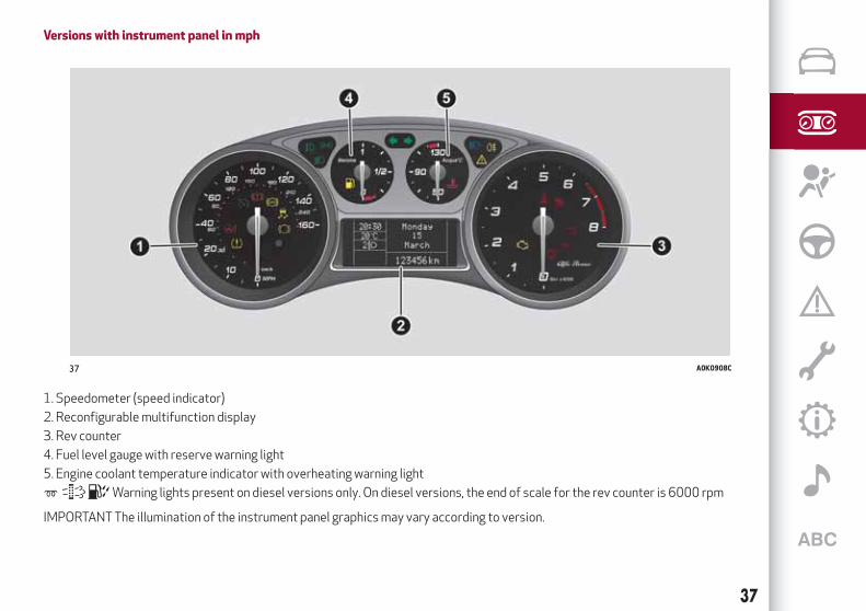
Versions with instrument panel in mph
1. Speedometer (speed indicator)
2. Reconfigurable multifunction display
3. Rev counter
4. Fuel level gauge with reserve warning light
5. Engine coolant temperature indicator with overheating warning light
Warning lights present on diesel versions only. On diesel versions, the end of scale for the rev counter is 6000 rpm
IMPORTANT The illumination of the instrument panel graphics may vary according to version.
37 A0K0908C
37

DISPLAY
The car is equipped with a reconfigurablemultifunction display that, according tothe previously applied settings, will showuseful driving information.
With the ignition key removed, thedisplay lights up and shows the time andtotal odometer reading (in km or miles)for a few seconds when a door isopened/closed.
RECONFIGURABLEMULTIFUNCTIONDISPLAYThe following information is shown on thedisplay (example given in fig. 38 ):
1: Time
2: Area reserved for messages(information, settings, etc)
3: Milometer (total distance coveredin km or miles).
4: Car status indications (e.g. doors open,
possible ice on road, etc.)/Start&Stopfunction indication (for versions/markets, where provided)/Gear ShiftIndicator (for versions/markets, whereprovided)
5: Headlight alignment position (only withdipped beam headlights on)
6: External temperature
The turbocharger pressure will appear onsome versions when “DYNAMIC” drivingmode is selected (see “Alfa DNA system”in this chapter).
GEARSHIFT INDICATOR
The GSI (Gear Shift Indicator) systemadvises the driver to change gear througha special indication on the display.
Through the GSI, the driver is notifiedthat the gear change will allow areduction in fuel consumption.
Therefore, for driving oriented towardsreducing fuel consumption, it is advisableto stick to “Natural” or “All Weather”mode and to follow the suggestions ofthe Gear Shift Indicator, where trafficconditions permit.
When the SHIFT UP icon is shown onthe display the GSI suggests the driver toup-shift, whereas if the SHIFT DOWNicon is displayed, the driver is advisedto down-shift.
The indication in the instrument panelremains on until the driver shifts gear orthe driving conditions go back to asituation where gearshifting is notrequired to improve consumption.
CONTROL BUTTONSfig. 39: to scroll up through the
displayed screen and the related optionsor to increase the displayed value.
SET/ : press briefly to access themenu and/or go to next screen or confirmthe selection. Hold down to go back tothe standard screen.
: to scroll through the screen andthe options downwards or to decreasethe value displayed.
IMPORTANT The buttons andbuttons activate different
functions according to the situation asfollows:
38 A0K0600C
39 A0K0541C
38
KN
OW
ING
TH
EIN
ST
RU
ME
NT
PAN
EL

within the menu, they allow you toscroll up or down through the options;
during setting operations, theyincrease or decrease values.
MAINMENUThe menu comprises a series of optionswhich can be selected using the buttons
and to access the differentselection and setting (Setup) operationsindicated below.
Some options have a submenu. The menucan be activated by briefly pressing theSET/ button .
The menu includes the following items:MENULIGHTINGSPEED WARNINGHEADLIGHT SENSOR (for
versions/markets where provided)RAIN SENSOR (for versions/markets,
where provided)TRIP B ACTIVATIONSET TIMESET DATEFIRST PAGE (for versions/markets,
where provided)AUTOCLOSEMEASUREMENT UNITLANGUAGEBUZZER VOLUMESEAT BELT BEEPSERVICEPASSENGER AIRBAG
DAYTIME RUNNING LIGHTSADAPTIVE LIGHTS (for
versions/markets, where provided)COURTESY LIGHTSEXIT MENU
Some menu items are shown on thenavigator display in models equippedwith radio-navigation systems (forversions/markets, where provided).
Selecting an option from themainmenuwithout a submenu:
press the SET/ button briefly toselect the main menu setting you wish tochange;
press the buttons or(with single presses) to select the
new setting;press the SET/ button briefly to
save the new setting and go back to theprevious main menu option.
Selecting an option from themainmenuwith a submenu:
briefly press the SET/ button todisplay the first submenu option;
press the buttons or(with single presses) to scroll
through all the submenu options;press the SET/ button briefly to
select the displayed submenu option andto open the relevant settings menu;
press the buttons or(with single presses) to select the
new setting for this submenu option;
press the SET/ button briefly tostore the new setting and go back to theprevious submenu option.
39

MENU ITEMS
IMPORTANT If there is anUconnect™system, some menu items are displayedand managed by the latter and not theinstrument panel (refer to thedescription in the Multimedia chapter orin the supplements available online).
Menu
Access to the Setup Menu.
Lights
(only with side lights on)
Adjustment (8 levels) of the brightness ofthe instrument panel, theUconnect™system controls (for versions/marketswhere provided) and the automaticclimate control system controls (forversions/markets where provided).
Speed warning
Vehicle speed limit setting (km/h or mph).When this is exceeded, the driver isnotified by an audible warning signal.
Headlight sensor
(for versions/markets, where provided)
Automatic switch on/off of lightsaccording to external light conditions.
The dusk sensor sensitivity can beadjusted according to 3 levels (level1=minimum sensitivity, level 2=averagesensitivity, level 3=maximum sensitivity).
Rain sensor
(for versions/markets, where provided)
Adjustment (4 levels) of the sensitivity ofthe rain sensor.
TripB activation
Activation (On) and deactivation (Off) ofTrip B display (partial trip counter). Formore information see the "Trip computer"section.
Set time
Clock setting through two sub-menus:“Time” and “Format”.
Set date
Date setting (day - month - year).
First page
(for versions/markets, where provided)
Selection of the information you wouldlike to see on the main screen. You canview the date or the trip distance.
Autoclose
Activation of the automatic locking of thedoors on exceeding the speed of20 km/h.
Measurement unit
Unit of measurement setting via threesubmenus: “Distances”, “Fuelconsumption” and “Temperature”.
If the set distance unit is "km", the displayallows the fuel consumption unit to be setas km/l or l/100km. If the set distance
unit is “mi” the fuel consumption unit willbe displayed in “mpg”.
Language
Display language selection.
Warning volume
Adjustment (8 levels) of the volume ofthe buzzer which accompanies thedisplay of failures/warnings.
Seat belt beep
This function can be displayed only afteran Alfa Romeo Dealership hasdeactivated the SBR system (seeparagraph “SBR system” in the “Safety”chapter).
Service
Display of information about km/mileageintervals or, for versions/markets, whereprovided, time intervals for car servicing.
Passenger airbag
Activation/deactivation of frontpassenger side airbag and side air bag forpelvis, chest and shoulder protection -Side bag
Daytime running lights
Activation/deactivation of DaytimeRunning Lights (DRL).
AFS adaptive lights
(for versions/markets, where provided)
Activation/deactivation of AFS adaptivelights (Adaptive Frontlight System).
40
KN
OW
ING
TH
EIN
ST
RU
ME
NT
PAN
EL

Courtesy lights
This function turns on the internalcourtesy lights for approximately25 seconds when the doors or luggagecompartment are opened using theremote control. The courtesy lights areturned off when the doors are closed orlocked using the remote control.
Exit Menu
Return to standard display screen.
TRIP COMPUTER
The Trip computer is used to displayinformation on car operation when thekey is turned to MAR. This function ischaracterised by two separate records,called “Trip A” and “Trip B”, where the car’s“complete missions” (journeys) arerecorded in a reciprocally independentmanner. Both memories can be reset: i.e.start of a new journey.
"Trip A" can be used to display the valuesrelating to:
RangeDistance travelled AAverage consumption AInstant consumptionAverage speed ATrip time (driving time) A
“Trip B” may be used to display thefigures relating to:
Distance travelled BAverage consumption BAverage speed BTrip time B (driving time).
The "Trip B" function may be disabled(see "Activating Trip B"). "Range" and"Instant consumption" values cannot bereset.
41

WARNING LIGHTSANDMESSAGES
IMPORTANT The warning light switches on in the instrument panel together with a dedicated message and/or acoustic signal whenapplicable. These indications are indicative and precautionary and as such must not be considered as exhaustive and/or alternativeto the information contained in the Owner Handbook, which you are advised to read carefully in all cases. Always refer to theinformation in this section in the event of a failure indication.
IMPORTANT Failure indications displayed are divided into two categories: very serious and less serious failures. Serious faults areindicated by a repeated and prolonged warning "cycle". Less serious faults are indicated by a warning "cycle" with a shorter duration.The display cycle of both categories can be interrupted. The instrument panel warning light will stay on until the cause of themalfunction is eliminated.
WARNING LIGHTS ON INSTRUMENTPANEL
Warning lights onpanel What it means What to do
LOW BRAKE FLUID/HANDBRAKE ENGAGEDThe warning light switches on when the key is turned toMAR-ON, but it should switch off after a few seconds.
Low brake fluid levelThe warning light (or symbol on the display) switches onwhen the level of the brake fluid in the reservoir fallsbelow the minimum level, possibly due to leaks in thecircuit.
Restore the brake fluid level, then check that the warninglight has switched off.If the warning light stays on, contact an Alfa RomeoDealership.
Handbrake engagedThe warning light (or symbol on the display) switches onwhen the handbrake is engaged. If the car is moving anacoustic signal is also emitted.
Release the handbrake, then check that the warning lighthas switched off.If the warning light (or symbol on the display) stays on,contact an Alfa Romeo Dealership.
42
KN
OW
ING
TH
EIN
ST
RU
ME
NT
PAN
EL

Warning lights onpanel What it means What to do
EBD FAILURE
The simultaneous switching on of the (red) and
(amber) warning lights with the engine on indicateseither an anomaly of the EBD system or that the systemis not available. In this case, the rear wheels may suddenlylock and the vehicle may swerve when braking sharply.
Drive very carefully to the nearest Alfa Romeo Dealershipto have the system inspected immediately.
AIRBAG FAILUREThe warning light switches on when the ignition key isturned to MAR, but it should switch off after a fewseconds.If the warning light switches on constantly, this indicatesa fault in the airbag system.
22) 23)
SEAT BELTS NOT FASTENED(for versions/markets, where provided)The warning light switches on constantly with the vehiclestationary and the driver’s seat belt not fastened.The warning light flashes and a buzzer sounds if the car isin motion and the front seat belts are not correctlyfastened.
For permanent deactivation of the acoustic signal(buzzer) of the S.B.R. (Seat Belt Reminder) systemcontact an Alfa Romeo Dealership. The system can bereactivated using the Setup Menu.
43

Warning lights onpanel What it means What to do
LOW ENGINE OIL PRESSUREWhen the key is turned to MAR the warning light comes on, but should go out as soonas the engine is started.After turning the ignition key to MAR, wait for about 2 seconds before starting theengine.The warning light switches on constantly together with a message on the display (forversions/markets, where provided) when the system detects that engine oilpressure is low.IMPORTANT Do not use the vehicle until the failure has been solved.IMPORTANT To find out the correct oil quantity, always check using the dipstick.
17)
DEGRADED ENGINE OIL (for versions/markets, where provided)The warning light will turn on flashing together with a dedicated message on thedisplay (for versions/markets where provided).Depending on the versions, the warning light flashing modes are as follows:- for 1 minute every two hours;- for 3 minute cycles with the warning light off for intervals of 5 seconds until oil ischanged.After the initial warning, each time the engine is started up, the warning light willcontinue to flash in the same mode, until the oil is changed. A specific message willappear on the display (for versions/markets, where provided) in addition to thewarning light. If the warning light flashes, this does not mean that there is a fault, butsimply informs that it is now necessary to change the oil as a result of regular use ofthe car. Engine oil deterioration is accelerated by:- mainly town use of the car which makes the DPF regeneration process morefrequent;- use of the vehicle for short drives, in which the engine does not have time to reachits regular operating temperature;- repeated interruptions of the regeneration process, signalled by the DPF warninglight switching on.
Contact an Alfa RomeoDealership as soon aspossible.
24) 25)
44
KN
OW
ING
TH
EIN
ST
RU
ME
NT
PAN
EL
Warning lights onpanel What it means What to do
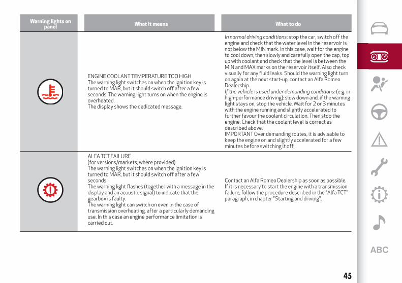
ENGINE COOLANT TEMPERATURE TOO HIGHThe warning light switches on when the ignition key isturned to MAR, but it should switch off after a fewseconds. The warning light turns on when the engine isoverheated.The display shows the dedicated message.
In normal driving conditions: stop the car, switch off theengine and check that the water level in the reservoir isnot below the MIN mark. In this case, wait for the engineto cool down, then slowly and carefully open the cap, topup with coolant and check that the level is between theMIN and MAX marks on the reservoir itself. Also checkvisually for any fluid leaks. Should the warning light turnon again at the next start-up, contact an Alfa RomeoDealership.If the vehicle is used under demanding conditions: (e.g. inhigh-performance driving): slow down and, if the warninglight stays on, stop the vehicle. Wait for 2 or 3 minuteswith the engine running and slightly accelerated tofurther favour the coolant circulation. Then stop theengine. Check that the coolant level is correct asdescribed above.IMPORTANT Over demanding routes, it is advisable tokeep the engine on and slightly accelerated for a fewminutes before switching it off.
ALFA TCT FAILURE(for versions/markets, where provided)The warning light switches on when the ignition key isturned to MAR, but it should switch off after a fewseconds.The warning light flashes (together with a message in thedisplay and an acoustic signal) to indicate that thegearbox is faulty.The warning light can switch on even in the case oftransmission overheating, after a particularly demandinguse. In this case an engine performance limitation iscarried out.
Contact an Alfa Romeo Dealership as soon as possible.If it is necessary to start the engine with a transmissionfailure, follow the procedure described in the "Alfa TCT"paragraph, in chapter "Starting and driving".
45

Warning lights onpanel What it means What to do
SPEED LIMIT EXCEEDED(for versions/markets, where provided)The warning light switches on when the car exceeds thespeed limit value set in the Setup Menu (e.g. 120 km/h).On some versions a message is shown along with asymbol on the display, and an acoustic signal is emitted.
46
KN
OW
ING
TH
EIN
ST
RU
ME
NT
PAN
EL

Warning lights onpanel What it means What to do
FUEL RESERVE/LIMITED RANGEThe warning light turns on when about 8 - 10 litres of fuelare left in the tank.When the remaining range is lower than approx. 50 km(or equivalent value in miles), on some versions thedisplay will show a warning message.
25)
REAR FOG LIGHTSThis warning light comes on when the rear fog lights areswitched on.
ABS FAILUREThe warning light switches on when the ignition key isturned to MAR, but it should switch off after a fewseconds.The warning light switches on to indicate a system fault.In this case the braking system maintains its efficiencyunaltered but without the advantage of the ABS system.
Drive carefully and contact an Alfa Romeo Dealership assoon as possible.
47

Warning lights onpanel What it means What to do
INJECTION/EOBD SYSTEM FAILUREIn normal conditions, when the ignition key is turned to MAR thewarning light switches on, but it should switch off as soon as the
engine is started. The operation of the warning light may bechecked by the traffic police using specific devices. Comply withthe laws and regulations of the country where you are driving.
18)
If the warning light remains on or switches on whilst driving, itmeans that the injection system is not working properly. Thewarning light on constantly signals a malfunction in thesupply/ignition system which could cause high exhaust emissions,a possible loss of performance, poor driveability and highconsumption.The warning light goes out after the fault disappears: theindication is stored in the system.
Under these conditions, the vehicle can continuetravelling at moderate speed withoutdemanding excessive effort from the engine.Prolonged use of the car with the warning lighton constantly may cause damage.Contact an Alfa Romeo Dealership as soon aspossible.
Petrol engines onlyIf the warning light flashes, it means that the catalytic convertermay be damaged.
In this case, release the accelerator pedal tolower the speed of the engine until the warninglight stops flashing. Continue the journey atmoderate speed, trying to avoid drivingconditions that may cause further flashing andcontact an Alfa Romeo Dealership as soon aspossible.
GLOW PLUG HEATING/GLOW PLUG HEATING FAILURE (dieselversions)This warning light switches on when the key is turned to MAR. Itwill switch off as soon as the heater plugs have reached a presettemperature. The engine can be started as soon as the warninglight switches off.IMPORTANT In mild or high temperature conditions, the warninglight comes on for a very short time only.
Glow plug preheating failureThe warning light will flash to indicate a failure in the glow plugpreheating system.
Contact an Alfa Romeo Dealership as soon aspossible.
48
KN
OW
ING
TH
EIN
ST
RU
ME
NT
PAN
EL

Warning lights onpanel What it means What to do
WATER IN DIESEL FILTER (Diesel versions)The warning light switches on constantly when driving to indicatethe presence of water in the diesel filter. 19)
DPF CLEANING (particulate trap) in progress (diesel versionswith DPF only)The warning light switches on when the ignition key is turned toMAR, but it should switch off after a few seconds. The warninglight switches on constantly to indicate that the DPF systemneeds to eliminate the trapped pollutants (particulate) throughthe regeneration process.The warning light does not come on during every DPFregeneration, but only when driving conditions require that thedriver is notified. To turn off the warning light, keep the car inmotion until the regeneration process is over.On average, the process lasts 15 minutes. Optimal conditions forcompleting the process are achieved by travelling at 60 km/hwith engine speed above 2000 rpm.When this warning light switches on, it does not indicate a vehiclefailure and thus it should not be taken to a workshop.
27)
49

Warning lights onpanel What it means What to do
iTPMS SYSTEMThe warning light switches on when the ignition key is turned toMAR, but it should switch off after a few seconds.
IMPORTANT Do not continue driving with one ormore flat tyres as handling may becompromised. Stop the vehicle, avoiding sharpbraking and steering. Repair immediately usingthe dedicated kit (see the "Replacing a wheel"paragraph in the "In an emergency" section) andcontact an Alfa Romeo Dealership as soon aspossible.
iTPMS failure/iTPMS temporarily deactivatedThe warning light flashes for about 75 seconds and then stays onconstantly (see “Operating conditions” paragraph) to indicatethat the system is temporarily deactivated or faulty.The system goes back to normal operation when the operatingconditions allow it. If this is not the case, carry out the Resetprocedure after restoring the normal operating conditions.
If the malfunction warning persists, contact anAlfa Romeo Dealership as soon as possible.
Low tyre pressureThe warning light switches on constantly to indicate that the tyrepressure is lower than the recommended value, in order toguarantee long tyre life and low fuel consumption, or to indicate aslow loss of pressure.In this way the iTPMS warns the driver that one or more tyresmay be flat and therefore probably punctured. In this case it isadvisable to restore the correct pressure value (see the "Wheels"paragraph in the "Technical specifications" section).Once the normal operating conditions of the vehicle are restored,carry out the Reset procedure.
In any situation in which the message on thedisplay is "See manual", it is ESSENTIAL to referto the contents of the "Wheels" paragraph in the"Technical specifications" section, strictlycomplying with the indications that you findthere.IMPORTANT Do not continue driving with one ormore flat tyres as handling may becompromised. Stop the vehicle, avoiding sharpbraking and steering.
ELECTRONIC STABILITY CONTROL (ESC) SYSTEMWhen the ignition key is turned to MAR, the warning lightswitches on, but should switch off as soon as the engine isstarted.Intervention by the system is indicated by the flashing of thewarning light: it indicates that the car is in critical stability andgrip conditions.If the warning light does not switch off, or if it stays on with theengine running, this indicates an anomaly in the ESC system.
Contact an Alfa Romeo Dealership as soon aspossible to have the problem diagnosed andresolved.
50
KN
OW
ING
TH
EIN
ST
RU
ME
NT
PAN
EL

Warning lights onpanel What it means What to do
ELECTRONIC STABILITY CONTROL (ESC) SYSTEM
ASR system failureWhen the ignition key is turned to MAR, the warning light switcheson, but should switch off as soon as the engine is started.The warning light will flash while driving to indicate that the ASRsystem is intervening.If the warning light does not switch off, or if it stays on with theengine running, this indicates a malfunction of the ASR system.
In this case, contact an Alfa Romeo Dealership assoon as possible.
Hill Holder failure
The warning light switches on together with the symbol on thedisplay to indicate a fault in the Hill Holder system.
In this case, contact an Alfa Romeo Dealership assoon as possible.
51

Warning lights onpanel What it means What to do
CRUISE CONTROL (for versions/markets, whereprovided)This warning light switches on when the ignition key isturned to MAR, but it should switch off after a fewseconds, if the Cruise Control is deactivated. Thewarning light switches on when the Cruise Control ring isturned to the ON position (see the “Cruise Control”paragraph in the "Knowing your vehicle" section).
SIDE LIGHTSThe warning light switches on when the side lights areactivated.
FOLLOW ME HOMEThe warning light will turn on when this device is active(see “Exterior lights”in the section “Knowing your car”).
DIPPED HEADLIGHTSThe warning light switches on when the dipped beamheadlights are turned on.
FRONT FOG LIGHTSThe warning light comes on when the front fog lights areturned on.
LEFT DIRECTION INDICATORThe warning light switches on when the directionindicator control lever is moved downwards or, togetherwith the right direction indicator, when the hazardwarning light button is pressed.
52
KN
OW
ING
TH
EIN
ST
RU
ME
NT
PAN
EL

Warning lights onpanel What it means What to do
RIGHT DIRECTION INDICATORThe warning light turns on when the direction indicatorcontrol lever is moved upwards or, together with the leftdirection indicator, when the hazard warning light buttonis pressed.
Warning lights onpanel What it means What to do
MAIN BEAM HEADLIGHTSThe warning light switches on when the main beamheadlights are turned on.
53

SYMBOLSONTHEDISPLAY
Symbol on the display What it means What to do
ALTERNATOR FAILUREThe symbol appears on the display in the event of a faultwith the alternator.
If the symbol continues to be displayed, contact an AlfaRomeo Dealership immediately.
DOOR OPEN(for versions/markets, where provided)The symbol appears on the display when one or moredoors or the tailgate are not perfectly closed. Anacoustic signal is activated with the doors open and thecar moving.On some versions the symbol also appears on the displaywhen the bonnet is not closed correctly.
DUAL PINION ACTIVE STEERING FAILURE(for versions/markets, where provided)The symbol appears on the display in the event of a faultwith the steering.In the event of a fault, you may not have steeringassistance and the effort required to operate thesteering wheel could be notably increased; steering is,however, still possible.
Contact an Alfa Romeo Dealership as soon as possible.
IMPORTANT Every time the battery is disconnected, thesteering must be initialised. This is indicated by theappearance of the icon. To carry out this procedure,simply turn the steering wheel all the way from one endto the other or drive in a straight line for about100 metres.
54
KN
OW
ING
TH
EIN
ST
RU
ME
NT
PAN
EL

Symbol on the display What it means What to do
FUEL CUT-OFF SYSTEMThe display will show the symbol if the fuel cut-offsystem intervenes.
For the procedure to restore the fuel cut-off system seethe “Controls" paragraph in the "Knowing your vehicle"section. If it is still not possible to restore the fuel supply,contact an Alfa Romeo Dealership.
EXTERIOR LIGHTS FAILUREThe symbol appears when a fault is detected on one ofthe following lights:
daytime running lights (DRL)
side lights
direction indicators
rear fog lights
number plate lights
reversing lightsThe fault relating to these lights may be caused by: one ormore blown fuses, one or more blown bulbs or a brokenelectrical connection.
Check, and if necessary replace the fuses involved, inaccordance with the "Fuse replacement" paragraph, inchapter "In an emergency". If this does not resolve thefault, check, and if necessary replace, the bulbs involved, inaccordance with the "External bulb replacement"paragraph, in chapter "In an emergency".Should this operation also fail to resolve the fault, contactan Alfa Romeo Dealership, for a comprehensive check ofthe electrical system.
BRAKE LIGHT FAILUREThe display will show the symbol if a fault in the brakelights is detected.
The fault may be caused by a blown bulb, a blownprotection fuse or an interruption of the electricalconnection.
DUSK SENSOR FAILURE(for versions/markets, where provided)The symbol will appear on the display if there is a fault inthe dusk sensor.
Go to an Alfa Romeo Dealership to have the fault fixed assoon as possible.
RAIN SENSOR FAILURE(for versions/markets, where provided)The symbol will appear on the display if there is a fault inthe rain sensor.
Go to an Alfa Romeo Dealership to have the fault fixed assoon as possible.
PARKING SENSOR FAILURE(for versions/markets, where provided)The symbol will appear on the display if there is a fault inthe parking sensors.
Go to an Alfa Romeo Dealership to have the fault fixed assoon as possible.
55

Symbol on the display What it means What to do
ALFA ROMEO CODE SYSTEM FAILURE/ALARMFAILURE(for versions/markets, where provided)The symbol appears on the display to indicate a faultwith the Alfa Romeo CODE system or alarm system (forversions/market, where provided).
Contact an Alfa Romeo Dealership as soon as possible.
Break-in attemptThe symbol appears on the display to indicate a break-inattempt.
Contact an Alfa Romeo Dealership as soon as possible.
FUEL RESERVE/LIMITED RANGE(for LPG versions only)The symbol appears when about 8 - 10 litres of fuel areleft in the tank. The first bar and the edges of the other3 bars of the LPG level indicator flash on the display.
GENERAL FAILURE(for versions/markets, where provided)The symbol appears in the circumstances indicated below.
In these cases contact an Alfa Romeo Dealership to havethe fault fixed as soon as possible.
Clutch overheatingThe symbol appears in the event of the clutch overheating.
Engine oil pressure sensor failureThe symbol appears when a fault is detected in the engine oil pressure sensor.
Fuel cut-offThe symbol appears when fuel-cut-off system is faulty.
BRAKE PAD WEAR(for versions/markets, where provided)The symbol appears on the display switches on when thefront or rear brake pads are worn.
Have them replaced as soon as possible.
56
KN
OW
ING
TH
EIN
ST
RU
ME
NT
PAN
EL

Symbol on the display What it means What to do
POSSIBLE ICE ON ROADA symbol appears on the display when the outsidetemperature falls to 3°C or below.
IMPORTANT In the event of outside temperature sensorfailure, the digits that indicate the value are replaced bydashes.
This symbol appears to suggest engaging a higher gear(upshifting).
The symbol appears to suggest engaging a lower gear(downshifting).
The switching on of this symbol indicates that the clutchpedal must be pressed for starting enablement.
START&STOP FAILURE
The symbol will be displayed continuously to indicatea Start&Stop system fault.
In these cases contact an Alfa Romeo Dealership to havethe fault fixed as soon as possible.
START&STOP SYSTEM ACTIVATION/DEACTIVATION(for versions/markets, where provided)
Start&Stop system activationWhen the system is is activated, the LED located on the
button is off (see the “Start&Stop” paragraph in thischapter).
Start&Stop system deactivationDeactivation of the Start&Stop system is indicated by the
symbol on the display.When the system is deactivated. the LED above the
button is on.
57

WARNING
22) If the warning light does not switch onwhen the ignition device ismoved toONor if it stays onwhen driving (together with themessage onthe display), theremight be a fault in the restraint systems; in this case, the airbags or pretensionersmay not deploy in the event of an accident or,in a lower number of cases, they could deploy erroneously. Before proceeding, contact an Alfa RomeoDealership to have the system checkedimmediately.23)A fault with thewarning light is signalled by illumination of the icon on the instrument panel display and by the flashing of passengerairbag disabledwarning light on the rearviewmirror. In addition, the airbag systemautomatically disables the airbag on the passenger's side (forversions/marketswhere provided). In this case, thewarning lightmay not indicate any faults with the restraint systems. Before proceeding,contact an Alfa RomeoDealership to have the system checked immediately.24) If thewarning light comes on, the exhausted engine oil should be changed as soon as possible, never drivemore than 500 km from the firstswitching-on of this warning light. Failure to observe the abovemay result in severe damage to the engine and invalidate thewarranty. Rememberthatwhen this warning light comes on, it does notmean that the level of engine oil is low, so if it flashes youmust not top up the engine oil.25) If thewarning light flasheswith the car inmotion, contact an Alfa RomeoDealership.26) If thewarning light (or the icon on the display) flasheswhilst driving, contact an Alfa RomeoDealership.27)Always drive at a speed appropriate to the traffic conditions, theweather and traffic regulations. The enginemay be switched off even if the
warning light is on: repeated interruptions of the regeneration process could cause an early deterioration of engine oil. For this reason it isalways advisable towait for the symbol to go off before turning off the engine, following the instructions above. Do not complete theDPFregeneration processwhen the vehicle is stopped.
IMPORTANT
17) If the warning light switches onwhen driving, stop the engine immediately and contact an Alfa RomeoDealership.18) If, turning the ignition device toMAR, thewarning light does not turn on or if it turns on steadily or flashingwhen travelling (on someversions together with themessage on the display), contact an Alfa RomeoDealership as soon as possible.19) The presence ofwater in the fuel system circuitmay cause severe damage to the injection systemand irregular engine operation. If thesymbol is displayed contact an Alfa RomeoDealership as soon as possible to bleed the system. If the above indications come on immediately
after refuelling, water has probably been introduced into the tank: stop the engine immediately and contact an Alfa RomeoDealership.
58
KN
OW
ING
TH
EIN
ST
RU
ME
NT
PAN
EL

The chapter that you are about to read is very important: itdescribes the safety systems with which the car is equipped and
provides instructions on how to use them correctly.
SAFETYACTIVE SAFETY SYSTEMS . . . . . . . . . . . . . . . . . . . . . . . .60iTPMS System (indirect Tyre Pressure Monitoring System) . . . . .62SEAT BELTS . . . . . . . . . . . . . . . . . . . . . . . . . . . . . . . . .64SBR SYSTEM (Seat Belt Reminder) . . . . . . . . . . . . . . . . . . .65PRE-TENSIONERS. . . . . . . . . . . . . . . . . . . . . . . . . . . . . .66CARRYING CHILDREN SAFELY . . . . . . . . . . . . . . . . . . . . . .68FITTING "UNIVERSAL" CHILD RESTRAINT SYSTEM (with seatbelts) . . . . . . . . . . . . . . . . . . . . . . . . . . . . . . . . . . . . . .69ISOFIX CHILD RESTRAINT SYSTEM SETUP . . . . . . . . . . . . . .72FRONT AIRBAGS. . . . . . . . . . . . . . . . . . . . . . . . . . . . . . .75SIDE AIRBAGS (SIDE BAGS - WINDOW BAGS) . . . . . . . . . . . . .79

ACTIVE SAFETYSYSTEMS
ABSSYSTEM
This system, which is an integral part ofthe braking system, prevents one or morewheels from locking and slipping in allroad surface conditions, irrespective ofthe intensity of the braking action,ensuring that the vehicle can becontrolled even during emergencybraking and optimising stoppingdistances.
System intervention
The driver can feel that the ABS systemhas come into action because the brakepedal pulsates slightly and the systemgets noisier: this is entirely normal withthe system operating.
33) 34) 35) 36) 37) 38) 39)
ASR (AntiSlip Regulation) SYSTEM
40) 41) 42)
This is an integral part of the ESC systemand automatically operates in the eventof one or both drive wheels slipping, lossof grip on wet roads (aquaplaning) andacceleration on slippery, snowy or icyroads, etc.
System intervention
The system operates on the enginepower and brakes.
This is indicated by the flashing of thewarning light on the instrument panel,to inform the driver that the car is incritical stability and grip conditions.
MSR (Motor SchleppmomentRegelung) SYSTEMThe system prevents the drive wheelsfrom possibly locking, which couldhappen, for example, if the acceleratorpedal is released suddenly or in the caseof a sudden downshifting in conditions ofpoor grip.
In this conditions, the engine brakingeffect could cause the drive wheels toslip, resulting in a loss of vehicle stability.In these situations, the systemintervenes, restoring torque to theengine in order to conserve vehiclestability and increase vehicle safety.
HBA (Hydraulic Brake Assist) SYSTEM
43) 44) 45)
The HBA system is designed to improvethe car’s braking capacity duringemergency braking: the HBA systemtherefore completes the ABS system.
Maximum assistance from the HBAsystem is obtained by continuouslypressing the brake pedal very quickly.
DSTSYSTEM (Dynamic SteeringTorque)
46)
The DST function uses the integration ofthe ESC system with the electric powersteering to increase the safety level ofthe whole vehicle.
In critical situations (braking on surfaceswith different grip conditions), throughthe DST function the ESC systemcontrols the steering to implement anadditional torque contribution on thesteering wheel, to suggest the mostcorrect manoeuvre to the driver.
The coordinated action of the brakes andsteering increases the sensation ofsafety and control of the vehicle.
EBDSYSTEMThe EBD system is an integral part of theESC system and intervenes duringbraking, distributing the brake forceoptimally between front and rear wheels.
This guarantees greater braking stabilityfor the car, preventing sudden locking ofthe rear wheels and the consequentinstability of the car.
ESC SYSTEM
The ESC system improves the directionalcontrol and stability of the car in variousdriving conditions.
60
SA
FE
TY

The ESC system corrects the car’sundersteer and oversteer, distributingthe brake force on the appropriatewheels. The torque supplied by theengine can also be reduced in order tomaintain control of the vehicle.
28) 29) 30) 31) 32)
The ESC system comprises the activesafety systems such as: ABS, EBD, ASR,HILL HOLDER, etc.
The ESC system switches onautomatically when the engine is startedand cannot be switched off.
System intervention
This is indicated by the flashing of thewarning light on the instrument panel,to inform the driver that the car is incritical stability and grip conditions.
CBC (Cornering Brake Control) SYSTEMThis system acts when braking oncorners, optimising the distribution ofbrake pressure on the four wheels: thesystem prevents the wheels on the insideof the corner (less affected by the weightof the car) from locking, ensuring betterstability and direction for the car.
HILL HOLDERSYSTEM
This is an integral part of the ESC systemand facilitates starting on uphill ordownhill slopes by operating the brakes:
IMPORTANT The Hill Holder system isnot a parking brake; therefore, neverleave the car without having engaged thehandbrake, turned the engine off andengaged first gear, so that it is parked insafe conditions (for further informationread the "Parking" paragraph in the"Starting and driving" chapter).
IMPORTANT There may be situations onsmall gradients (less than 8%), with carladen, in which the Hill Holder systemmay not activate, causing a slightreversing motion and increasing the riskof collision with another vehicle or object.The driver is, in any case, responsible forsafe driving.
“ELECTRONIC Q2” SYSTEM (“E-Q2”)The "Electronic Q2" system intervenesduring acceleration on corners, brakingthe inner drive wheel and thus increasingthe traction of the outer wheel (whichbears more of the car’s weight): thetorque is thus distributed optimallybetween the drive wheels in accordancewith the driving conditions and roadsurface, permitting particularly effective,sporty driving.
"PRE-FILL" SYSTEM (RAB - Ready AlertBrake)(only with 'Dynamic" mode activated)
This function activates automatically ifthe accelerator pedal is released rapidly,reducing the brake pad travel (both at
front and back), with the aim of preparingthe braking system and enhancing itsresponsiveness, thus reducing thestopping distance in the event ofsubsequent braking.
WARNING
28) The ESC system cannot alter the naturallaws of physics, and cannot increase grip,which depends on the condition of the road.29) The ESC system cannot preventaccidents, including those due to excessivespeed on corners, driving on low-gripsurfaces or aquaplaning.30) The capability of the ESC systemmustnever be tested irresponsibly anddangerously, in such away as to compromisepersonal safety and the safety of others.31) For the correct operation of the ASRsystem, the tyresmust of necessity be thesamemake and type on all wheels, in perfectcondition and, above all, of the prescribedtype and dimensions.32)Do not take unnecessary risks, even ifyour vehicle is fittedwith the ESC andASRsystems. Your driving stylemust always besuited to the road conditions, visibility andtraffic. The driver is always responsible forroad safety.33)When the ABS intervenes and you feelthe brake pedal pulsating, do not reduce thepressure, but hold it down firmly andconfidently; in doing so youwill brake in theshortest distance possible, depending on thecurrent road conditions.
61

34) To obtain themaximumefficiency of thebraking system, a bedding-in period of about500 km is needed: during this period it isbetter to avoid sharp, repeated andprolonged braking.35) If the ABS intervenes, this indicates thatthe grip of the tyres on the road is nearing itslimit: youmust slow down to a speedcompatible with the available grip.36) The ABS cannot overrule the naturallaws of physics, and cannot increase the gripavailable according to the condition of theroad.37) The ABS cannot prevent accidents,including those due to excessive speed oncorners, driving on low-grip surfaces oraquaplaning.38) The capability of the ABSmust never betested irresponsibly and dangerously, insuch away as to compromise personalsafety and the safety of others.39) For the correct operation of the ABS, thetyresmust of necessity be the samemakeand type on all wheels, in perfect conditionand, above all, of the prescribed type anddimensions.40) The ASR cannot overrule the naturallaws of physics, and cannot increase the gripavailable according to the condition of theroad.41) The ASR system cannot preventaccidents, including those due to excessivespeed on corners, driving on low-gripsurfaces or aquaplaning.42) The capability of the ASRmust never betested irresponsibly and dangerously, insuch away as to compromise personalsafety and the safety of others.
43) TheHBA system can’t overrule thenatural laws of physics, and can’t increasethe grip available according to the conditionof the road.44) TheHBA system cannot preventaccidents, including those due to excessivespeed on corners, driving on low-gripsurfaces or aquaplaning.45) The features of the HBA systemmustnever be tested in imprudent or dangerousways, with the possibility of putting thesafety of the driver, occupants or other roadusers at risk.46)DST is an aid for driving and does notrelieve the driver of responsibility for drivingthe vehicle.
iTPMSSystem (indirect TyrePressureMonitoring System)(for versions/markets, where provided)
DESCRIPTION
The car can be equipped with the iTPMS(indirect Tyre Pressure MonitoringSystem) which monitors the tyre inflationstatus thanks to wheel speed sensors.
The system warns the driver if one ormore tyres are flat by the dedicatedwarning light continuously on and awarning message on the display.
If one tyre only is flat, the system canindicate its position: it is in any caserecommended to check the pressure onall four tyres.
This indication is displayed also whenturning the engine off and on again untilthe RESET procedure is carried out.
RESETPROCEDURE
The iTPMS needs an initial "self-learning"phase (with length depending on thedriving style and road conditions: optimalconditions being driving on a straightroad at 80 km/h for at least 20 minutes)which starts when the RESET procedureis carried out.
The Reset procedure must be carried out:each time tyre pressure is modified;when even only one tyre is changed;when tyres are rotated/inverted;
62
SA
FE
TY

when the space-saver wheel is fitted.
Before carrying out the RESET, inflatethe tyres to the rated pressure valuesspecified in the inflation pressure table(see "Wheels" paragraph in the "Technicalspecifications" chapter).
If the RESET is not carried out, in allabove cases, the warning light maygive false indications on one or moretyres.
To carry out the RESET, with the carstopped and the ignition key at MAR-ON,press the button fig. 40 on thedashboard for 2 seconds; after theRESET, the display shows a dedicatedmessage, indicating that "self-learning"has started.
OPERATING CONDITIONS
47) 48) 49) 50) 51) 52)
The system is active for speeds above15 km/h.
In a few situations such as sporty driving,particular conditions of the road surface(e.g. icy, snowy, unsurfaced roads) thesignalling may be delayed or partial indetecting the contemporary deflation ofmore than one tyre.
Under special conditions (e.g. vehicleloaded asymmetrically on one side,towing a trailer, damaged or worn tyre,fitting the space-saver wheel, use of the"Fix&Go Automatic" kit, fitting snowchains, fitting different tyres on theaxles) the system may give falseindications or be temporarilydeactivated.
If the system is temporarily deactivated,the warning light flashes for about75 seconds and then is continuously on;at the same time, the display shows adedicated message.
This indication is displayed also after theengine has been switched off and then onagain if the correct operating conditionsare not restored.
IMPORTANTNOTES
WARNING
47) If the system signals a pressuredecrease on a specific tyre, it isrecommended to check the pressure on allfour tyres.48) The iTPMSdoes not relieve the driverfrom the obligation to check the tyrepressure everymonth; it is not to beconsidered a system to replacemaintenanceor a safety system.49) Tyre pressuremust be checkedwithtyres cold. Should it become necessary forwhatever reason to check pressurewithwarm tyres, do not reduce pressure eventhough it is higher than the prescribed value,but repeat the checkwhen tyres are cold.50) The iTPMS cannot indicate sudden tyrepressure drops (for examplewhen a tyrebursts). In this case, stop the vehicle, brakingwith caution and avoiding abrupt steering.51) The system only warns that the tyrepressure is low: it is not able to inflate them.52) Insufficient tyre inflation increases fuelconsumption, reduces the tread duration andmay affect the capacity to drive safely.
40 A0K0608C
63

SEATBELTS
USINGTHE SEATBELTSThe belt should be worn keeping thetorso straight and rested against thebackrest.
To fasten the seat belts, hold the tongue1 fig. 41 and insert it into the buckle 3,until it clicks into place.
On removal of the belt, if it jams, let itrewind for a short stretch, then pull it outagain without jerking.
To unfasten the seat belts, press button2 and guide the seat belt with your handwhile it is rewinding, to prevent it fromtwisting. 53)
The retractor may lock when the vehicleis parked on a steep slope: this isperfectly normal. Furthermore, the reelmechanism locks the belt if it is pulled
sharply or in the event of sudden braking,collisions and high-speed bends.
The rear seat is fitted with inertia seatbelts with three anchor points and aretractor.
Wear the rear seat belts as illustrated infig. 42.
IMPORTANT The backrest is correctlysecured when the red band 1 fig. 43 onthe backrest folding handles2 disappears. This red band indicatesthat the backrest is not secured.
IMPORTANT When putting the rear seatsback to their normal position, make surethe seat belts are positioned so they areready to use. 55)
WARNING
53)Never press button 2when travelling.54)Remember that, in the event of anaccident, the rear seat passengers notwearing seat belts are exposed to a veryserious risk and also represent a seriousdanger for the front seat occupants.55)Make sure that the backrest is correctlysecured on both sides (red bands not visible)to prevent it frommoving forward in theevent of sharp braking, causing injuries tooccupants.
41 A0K0659C
42 A0K0921C
43 A0K0628C
64
SA
FE
TY

SBRSYSTEM (Seat BeltReminder)This system comprises an acousticwarning which, in conjunction with thewarning lights flashing on theinstrument panel, warns the front seatpassengers if their seat belt has not beenfastened.
On some versions there is also a panelfig. 44 (provided as an alternative to thewarning light on the instrument panel)located above the rear-view mirror, whichwarns the front and back seatpassengers via acoustic and visualsignals if their seat belts have not beenfastened.
Contact an Alfa Romeo Dealership todeactivate this acoustic warningpermanently.
The acoustic warning can be reactivatedat any time through the Setup Menu (see
"Menu options" paragraph in the“Knowing the instrument panel” chapter).
The warning lights fig. 44 may be red orgreen and operate as follows:
1 = front left seat (driver status forleft-hand drive versions)
2 = rear left seat (passenger);3 = rear centre seat (passenger)4 = rear right seat (passenger);5 = front right seat (passenger status
for left-hand drive versions).
FRONTSEATS (warning light 1 = driverand 5 = passenger)
Driver
If the driver is the only occupant and theseat belt is not fastened, when 20 km/his exceeded or when travelling at a speedfrom 10 to 20 km/h for longer than5 seconds, a buzzer sequence will bestarted (front seats) consisting of a tonefor 6 seconds followed by a 90 secondbeep.The warning light will blink.
The warning lights will stay on constantlyat the end of the cycle until the engine isstopped. The acoustic signal will beinterrupted immediately when thedriver’s seat belt is fastened and thewarning light will turn green.
The reminder cycle (acoustic and visual)will be repeated as described above andthe red warning light will flash if the seatbelt is unfastened again while travelling.
Passenger
A similar solution applies for the frontpassenger, with the difference that thewarning light turns green and the signal isinterrupted also when the passengerleaves the car.
It both front seat belts are unfastenedwhile the vehicle is travelling a fewseconds apart, the acoustic indicationwill refer to the most recent event andthe two warning lights will proceed withthe visual indication independently.
REARSEATS (warning light 2, 3 and 4)
The reminder cycle is run only when anyseat belt is unfastened (red blinking).
In this condition, the warning light for theseat belt which has been unfastened willstart flashing red for approximately30 seconds. An acoustic signal is alsoemitted.
The visual indication (blinking red) willstart and end independently for eachwarning light if several seat belts areunfastened. The warning light willbecome green when the relevant seatbelt is fastened again.
After about 30 seconds from the lastindication, the warning lights for rearseats will switch off, irrespective of thebelt conditions (red or green).
44 A0K0075C
65
IMPORTANTNOTES
All warning lights will remain off if all theseat belts (front and rear) are alreadyfastened when the key it turned to MAR.
All the warning lights will come on whenat least one belt changes from fastenedto unfastened status or vice versa.
PRE-TENSIONERS
56) 57)
The vehicle is equipped with front seatbelt pretensioners, which draw back theseat belts by several centimetres in theevent of a strong frontal impact. Thisguarantees the perfect adherence of theseat belts to the occupant's bodiesbefore the retention action begins.
It is evident that the pretensioners haveoperated when the belt withdrawstoward the retractor.
This car is also equipped with a secondpretensioner (fitted in the kick platearea). Its activation is signalled by theshortening of the metal cable.
A slight discharge of smoke may beproduced during the activation of thepretensioner which is not harmful anddoes not involve any fire hazard.
IMPORTANT To obtain the highestdegree of protection from the action ofthe pretensioner, wear the seat belt tightto the chest and pelvis.
The pretensioner does not require anymaintenance or lubrication: any changesto its original conditions will invalidate itsefficiency. If, due to unusual naturalevents (floods, sea storms, etc.), thedevice has been affected by water and/ormud, contact an Alfa Romeo Dealershipto have it replaced.
LOAD LIMITERSTo increase passenger safety, the frontseat belt reels contain a load limiterwhich allows the force acting on the chestand shoulders to be modulated during thebelt restraining action in the event of afrontal impact.
GENERAL INSTRUCTIONS FORUSINGTHE SEATBELTS
Respect and ensure that all the otheroccupants of the vehicle comply with thelocal laws in force regarding the use ofseat belts. Always fasten the seat beltsbefore starting off.
58) 59)
Seat belts must also be worn by pregnantwomen: the risk of injury in the event ofan accident is reduced for them and theunborn child if they are wearing a seatbelt.
Pregnant women must position the lowerpart of the belt very low down so that itpasses over the pelvis and under theabdomen fig. 45.
66
SA
FE
TY

The belt must not be twisted. The upperpart must pass over the shoulder andcross the chest diagonally. The lower partmust adhere to the pelvis fig. 46, not tothe abdomen of the occupant. Never usedevices (clips, clamps, etc.) that hold theseat belt away from your body.
Each seat belt must be used by only oneperson. Never travel with a child sittingon a passenger’s lap using a single belt to
protect them both fig. 47. In general, donot place any objects between the personand the belt.
SEATBELTSMAINTENANCEAlways use the seat belt well
stretched and never twisted; make surethat it is free to run without obstructions;
replace the belt after an accident of acertain severity even if it does not appearto be damaged. Always replace the belt ifthe pretensioners were deployed;
check seat belt operation as follows:attach the seat belt and pull it hard;
prevent the retractors from gettingwet: their correct operation is onlyguaranteed if water does not get inside;
replace the seat belt when there iswear or cuts.
WARNING
56) The pretensionermay be used only once.After its activation, contact an Alfa RomeoDealership to have it replaced.57)Removing or tamperingwith seat beltand pretensioner components is strictlyprohibited. Any intervention on thesecomponentsmust be performed by qualifiedand authorised technicians. Always contacta dedicated Alfa RomeoDealership.58) Formaximum safety, keep the backrestupright, lean back into it andmake sure theseat belt fits closely across your chest andpelvis. Always fasten the seat belts for boththe front and rear seats! Travellingwithoutwearing seat belts will increase the risk ofserious injury and even death in the event ofan accident.59) If the belt has been subjected to highlevels of stress, for example after anaccident, it should be changed completelytogether with the attachments, attachmentfixing screws and the pretensioner. In fact,even if the belt has no visible defects, it mayhave lost its resilience.
IMPORTANT
20)Operations which lead to impacts,vibrations or localised heating (over 100°Cfor amaximumof six hours) in the areaaround the pretensionermay cause damageormake it deploy. Contact an Alfa RomeoDealership should intervention be necessaryon these components.
45 A0K0250C
46 A0K0012C
47 A0K0013C
67

CARRYING CHILDRENSAFELYFor optimal protection in the event of animpact, all occupants must be seated andwearing adequate restraint systems,including newborn and other children!
This prescription is compulsory in all ECcountries according to EC Directive2003/20/EC.
Children below the height of 1.50 metresand up to 12 years must be protectedwith suitable restraint systems and beseated on the rear seats. Statistics onaccidents indicate that the rear seatsoffer greater safety for children.
Compared with an adult, a child's head islarger and heavier in proportion to theirbody and the child's muscular and bonestructures are not fully developed.Therefore, correct restraint systemsother than adult seat belts are necessaryto reduce as much as possible the risk ofinjuries in case of accident, braking orsudden manoeuvre.
Children must be seated safely andcomfortably. Depending on thecharacteristics of the child restraintsystems used, you are advised to keepchildren in rearward facing child restraintsystems for as long as possible (at leastuntil 3-4 years old), since this is the mostprotected position in the event of animpact. 60) 61) 62) 63)
The choice of the most suitable childrestraint device depends on the weight ofthe child; there are various types of childrestraint systems and you are advisedalways to choose the one that is mostsuitable for the child.
When over 1.50 m in height, from thepoint of view of restraint systems,children are considered as adults andwear seat belts normally.
In Europe the characteristics of childrestraint systems are ruled by theregulation ECE-R44, dividing them intofive weight groups:
Group Weight groups
Group 0up to 10 kg in
weight
Group 0+up to 13 kg in
weight
Group 1 9-18 kg
Group 2 15-25 kg
Group 3 22 - 36 kg
All restraint devices must bear thecertification data, together with thecontrol mark, on a label solidly fixed tothe child restraint system which mustnever be removed.
Lineaccessori MOPAR®includes child
restraint systems for each weight group.
These devices are recommended havingbeen specifically tested for Alfa Romeocars.
WARNING
60)SEVEREDANGERWhen a frontpassenger airbag is fitted, do not installrearward facing child restraint systems onthe front passenger seat. Deployment of theairbag in an accident could cause fatalinjuries to the child regardless of theseverity of the collision. It is advisable toalways carry children in a child restraintsystemon the rear seat, which is themostprotected position in the event of a collision.61)On the sun visor there is a label withsuitable symbols reminding the user that it iscompulsory to deactivate the airbag if arearward facing child restraint system isfitted. Always complywith the instructionson the passenger side sun visor (see the"Supplementary Restraint System (SRS) -Airbag" paragraph).62)Should it be necessary to carry a child onthe passenger side front seat in a rear facingchild restraint system, the passenger sidefront airbag and side bagmust bedeactivated through the displaymainmenu(see the "Display" paragraph, "Knowing theinstrument panel" chapter), verifyingdeactivation by checkingwhether theOFF LED has switched on in the trim
located on the dashboard.Move thepassenger's seat as far back as possible toavoid contact between the child seat and thedashboard.
68
SA
FE
TY

63)Do notmove the front or rear seat if achild is seated on it or on the dedicated childrestraint system
FITTING "UNIVERSAL" CHILDRESTRAINTSYSTEM (with seatbelts)
GROUP0 and 0+
65) 66) 67) 68) 69)
Babies up to 13 kg must be carried with arear facing child restraint system of atype as shown in fig. 48 which, supportingthe head, does not induce stress on theneck in the event of suddendecelerations.
The child restraint system is secured bythe vehicle seat belts, as shown infig. 48 and it must restrain the child inturn with its own belts.
GROUP 1
64) 65) 66) 67) 68) 69)
Children of weight from 9 to 18 kg maybe transported in forward facing childrestraint systems fig. 49.
GROUP 2
65) 66) 67) 68) 69)
Children from 15 to 25 kg may berestrained directly by the car seat beltsfig. 50.
In this case, the child restraint system isused to position the child correctly withrespect to the seat belts so that thediagonal belt section crosses the child’s
48 A0K0014C
49 A0K0129C
50 A0K0016C
69

chest and not the neck, and the lower partis snug on the pelvis not the abdomen.
GROUP 3
65) 66) 67) 68) 69)
For children between 22 kg and 36 kg,there are dedicated restraint systemsthat allow the seat belt to be worncorrectly.
The fig. 51 shows the correct childpositioning on the rear seat.
Children over 1.50 m in height can wearseat belts like adults.
51 A0K0017C
70
SA
FE
TY

PASSENGERSEATCOMPLIANCEWITHREGULATIONSONUNIVERSAL CHILD RESTRAINTSYSTEMUSE
According to the European Directive 2000/3/EC the suitability of each passenger seat position for the fixing of universal childrestraint systems is shown in the following table:
Group Weight groups Front passenger's seat (*) Rear (side and central) seats
Group 0, 0+ up to 13 kg U (**) U
Group 1 9-18 kg U (**) U
Group 2 15-25 kg U (**) U
Group 3 22-36 kg U (**) U
(*) IMPORTANT: NEVER fit a rearward-facing child seat in the front passenger seat if the airbag is active. If you wish to fit a rearward-facing child seatin the front passenger seat, first deactivate the relative airbag (see instructions in the paragraph (Supplementary protection system (SRS) –Airbag”)
U (**) With a height adjustable seat, put the backrest in the vertical position.U= suitable for child restraint systems of the “Universal” category, according to European Standard EEC-R44 for the specified “Groups”.
WARNING
64)Child restraint systemswith Isofix attachments are available for a safe anchoring to the seatwithout using the car seat belts. See paragraph"Isofix child restraint system setup" for the fitting instructions.65) The diagram is indicative and for fitting purposes only. Fit the child restraint systemaccording to the instructions, whichmust be included.66)When the child restraint system is not used, secure it with the seat belt or with the ISOFIX anchorages, or remove it from the vehicle. Do notleave it unsecured inside the passenger compartment. In this way, in the case of sudden braking or an accident, it will not cause injuries to theoccupants.67)After installing a child restraint system, do notmove the seat: always remove the child restraint systembeforemaking any adjustment.68)Alwaysmake sure that the diagonal section of the seat belt does not pass under the arms or behind the back of the child. In the event of anaccident the seat belt will not be able to secure the child, with the risk of injury, including fatal injury. Therefore the childmust alwayswear the seatbelt correctly.69) Incorrect fitting of the child restraint systemmay result in an inefficient protection system. In the event of an accident the child restraintsystemmay become loose and the childmay be injured, even fatally.When fitting a restraint system for newborns or children, strictly complywiththe instructions provided by theManufacturer.
71

ISOFIX CHILD RESTRAINTSYSTEMSETUPThe vehicle is equipped with ISOFIXanchorages, a new standard which makesfitting a child restraint system quick,simple and safe.
Traditional child restraint systems can befitted alongside Isofix child restraintsystems on different seats in the samecar.
As an example, fig. 52 shows an exampleof a Universal Isofix child restraintsystem for weight group 1. 65)
The other weight groups are covered byspecific Isofix child restraint systems,which can be used only if specificallytested for this car (see list of carsprovided with the child restraint system).
IMPORTANT The central rear seat is notapproved for any type of Isofix childrestraint system.
INSTALLINGAUNIVERSAL ISOFIXCHILD RESTRAINTSYSTEMProceed as follows:
attach the child restraint system tothe special lower metal rings 2 fig. 53,located inside the rear seat backrest (toaccess the rings lift hinge 1);
secure the upper belt (availabletogether with the child restraint system)to the special attachments 1fig. 54 located in the rear part of thebackrest.
It is possible to have a mixed assembly oftraditional child restraint systems andUniversal Isofix ones. Remember thatwhen using a Universal Isofix childrestraint system, you can only useapproved child restraint systems withthe marking ECE R44 (R44/03 orsuperior) “Universal Isofix”.
The Universal Isofix "Duo Plus" child seatand the special "G 0/1 S" seat areavailable from Lineaccessori MOPAR ®.
For any further installation/usage details,refer to the “Instruction Manual”provided with the child restraint system.
71) 72) 73) 74) 75)
52 A0K0018C
53 A0K0510C
54 A0K0511C
72
SA
FE
TY

SUITABILITYOF PASSENGERSEATS FOR ISOFIX CHILD RESTRAINTSYSTEMUSE
The table below shows the various installation possibilities for Isofix child restraint systems on seats fitted with Isofix attachmentsin accordance with European standard ECE 16.
Weight group Child restraint system position Isofix size class Rear side seats
Group 0 up to 10 kg Rear facing E IL (*)
Group 0+ up to 13 kg
Rear facing E IL (*)
Rear facing D IL (*)
Rear facing C IL (*)
Group 1 from 9 up to 18 kg
Rear facing D IL (*)
Rear facing C IL (*)
Forward facing B IUF
Forward facing BI IUF
Forward facing A IUF
IL suitable for certain Isofix child restraint systems of the categories "specific vehicles", restricted" or "semiuniversal"(*) the Isofix child restraint system can be installed by adjusting the front seatIUF: suitable for Isofix child restraint systems to be positioned in forward facing position, universal class (fitted with third upper mounting),
type-approved for the relevant weight group.
73

Main recommendations to carrychildren safely
Install the child restraint systems onthe rear seat, which is the most protectedposition in the event of an impact.
Keep children in rearward facing childrestraint systems for as long as possible,at least until 3–4 years old.
Should a rearward facing childrestraint system be installed on the rearseats, it is advisable to position it as farforward as the position of the front seatallows.
If the passenger side front airbag isdeactivated always check the permanentswitching on of the warning light inthe trim above the interior rear viewmirror to make sure that it has actuallybeen deactivated.
Carefully follow the instructionssupplied with the child restraint systemitself. Keep the instructions in the vehiclealong with the other documents and thishandbook. Do not use second-hand childrestraint systems without instructions.
Only one child is to be strapped intoeach restraint system; never carry twochildren simultaneously.
Always check that the seat belts donot rest on the child’s neck.
Always check that the seat belt is wellfastened by pulling on it.
While travelling, do not let the child sitincorrectly or unfasten the belts.
Never allow a child to put the belt'sdiagonal section under an arm or behindtheir back.
Never carry children on your lap, evennewborns. No one can hold a child in thecase of an accident.
In the event of an accident, replace thechild restraint system with a new one. Inaddition, and depending on the type ofchild restraint system installed, replacethe seat belt with which the childrestraint system was connected.
WARNING
70) The diagram is indicative and for fittingpurposes only. Fit the child restraint systemaccording to the instructions, whichmust beincluded.71) If a Universal ISOFIX child seat systemis not fixed to all three anchorages, it will notbe able to protect the child correctly. In acrash, the child could be seriously or fatallyinjured.72) Fit the child restraint systemwhen thecar is stationary. The child restraint systemis correctly secured to the bracketswhenyou hear the click. Follow the instructions forassembly, disassembly and positioning thattheManufacturermust supplywith the childrestraint system.73)Do not use the same lower anchorage toinstall more than one child restraint system.
74) Fit the child restraint systemwhen thecar is stationary. The child restraint systemis correctly secured to the bracketswhenyou hear the click. Follow the instructions forassembly, disassembly and positioning thattheManufacturermust supplywith the childrestraint system.75) If the vehicle was involved in an accidentof a certain severity, have the ISOFIXanchorages and the child restraint systemreplaced.
74
SA
FE
TY
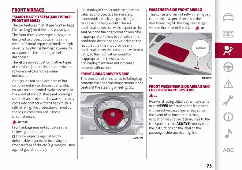
FRONTAIRBAGS
“SMARTBAG” SYSTEM (MULTISTAGEFRONTAIRBAGS)The car features multistage front airbags(“Smart bag”) for driver and passenger.
The front driver/passenger airbags aredesigned to protect occupants in theevent of frontal impacts of medium-highseverity, by placing the bag between theoccupant and the steering wheel ordashboard.
Therefore non-activation in other typesof collisions (side collisions, rear shunts,roll-overs, etc.) is not a systemmalfunction.
Airbags are not a replacement of butcomplementary to the seat belts, whichyou are recommended to always wear. Inthe event of impact, those not wearing aseat belt are projected forwards and maycome into contact with the bag which isstill inflating. The protection offered bythe bag is compromised in thesecircumstances.
76) 77) 79)
Front airbags may not activate in thefollowing situations:
frontal impacts against highlydeformable objects not involving thefront surface of the car (e.g. wing collisionagainst guard rail, etc.);
jamming of the car underneath othervehicles or protective barriers (e.g.underneath a truck or a guard rail) as, inthis case, the bags would offer noadditional protection with respect to theseat belt and their deployment would beinappropriate. Failure to activate in theconditions described above is due to thefact that they may not provide anyadditional protection compared with seatbelts, so their activation would beinappropriate. In these cases,non-deployment does not indicate asystem malfunction.
FRONTAIRBAGDRIVER'S SIDEThis consists of an instantly inflating bagcontained in a special compartment in thecentre of the steering wheel fig. 55.
PASSENGERSIDE FRONTAIRBAGThis consists of an instantly inflating bagcontained in a special recess in thedashboard: fig. 56 this bag has a largervolume than that of the driver. 78)
FRONTPASSENGERSIDE AIRBAGANDCHILD RESTRAINTSYSTEMS
80)
Rearward facing child restraint systemsmustNEVER be fitted on the front seatwith an active passenger airbag since inthe event of an impact the airbagactivation may cause fatal injuries to thetransported child.ALWAYS comply withthe instructions on the label on thepassenger side sun visor fig. 57.
55 A0K0364C
56 A0K0135C
75

Deactivating passenger side airbags:front airbag and side bag for pelvis,chest and shoulders protection (Sidebag)
If a child must be carried on the front seatin a rear facing child restraint system,deactivate the passenger side frontairbag and side bag for pelvis, chest andshoulder protection (Side bag). Todeactivate the airbags use the displayMenu (see the instructions in the"Display" paragraph, "Knowing theinstrument panel" chapter).
With airbags deactivated, a warning lightlights up on the instrument panel in
the trim located above the internalrearview mirror fig. 58.
With front passenger airbag on, when theignition key is turned to MAR, the warninglight switches on constantly for severalseconds and then it should switch off.
If the warning light flashes, thisindicates a fault in the warning light .Before proceeding, contact an AlfaRomeo Dealership to have the systemchecked immediately.
On moving the ignition device to MAR,the warning light switches on for afew seconds. If not, contact an AlfaRomeo Dealership. During the firstseconds, the activation of the warninglight does not actually show thepassenger protection status, but onlytests its correct operation. After a test ofa few seconds, the warning light willindicate the status of the passengerairbag protection.
Passenger's protection active: warninglight off.
Passenger protection deactivated: theOFF: the warning light switches onwith a steady light.
The warning light may light up withvarious intensity levels depending on thevehicle conditions. The intensity may varyduring the same key cycle.
57 A0K0918C 58 A0K0660C
76
SA
FE
TY

PASSENGERSIDE FRONTAIRBAGANDCHILD RESTRAINTSYSTEMS: IMPORTANT
59 J0A0215
77

WARNING
76)Do not apply stickers or other objects on the steeringwheel, on the dashboard in the passenger side airbag area, on side upholstery on the roofor on the seats. Never put objects (e.g. mobile phones) on the passenger's side dashboard since they could interferewith correct inflation of theairbag and also cause serious injury to the passengers.77)Always drive keeping your hands on the steeringwheel rim so the airbag can inflate freely if necessary. Do not drivewith your body bentforward. Keep the back of your seat upright and lean back into it.78)When there is an active passenger airbag, DONOT install rearward facing child restraint systems on the front seat. Deployment of the airbagin an accident could cause fatal injuries to the child regardless of the severity of the impact. Therefore, always deactivate the passenger sideairbagwhen a rearward facing child restraint system is installed on the front passenger seat. The front passenger seatmust also be positionedback as far as possible in order to prevent the child restraint system from coming into contact with the dashboard. Immediately reactivate thepassenger airbag as soon as the child restraint system has been removed.79) To deactivate the airbags, see the “Knowing your car” section, “Menu items” paragraph.80)A failure of the warning light is indicated by the warning light switching on. In addition, the airbag systemautomatically disables theairbag on the passenger's side (for versions/marketswhere provided). Before proceeding, contact an Alfa RomeoDealership to have the systemchecked immediately.
78
SA
FE
TY

SIDE AIRBAGS (SIDE BAGS -WINDOWBAGS)To increase protection of occupants incase of side collision, the car is equippedwith front side bags for pelvis, chest andshoulder protection (side bags) for thedriver and the passenger and airbagsprotecting the head of front and rearoccupants (window bags).
Non-activation of side bags in othertypes of collisions (front collisions, rearshunts, roll-overs, etc.) is not a systemmalfunction.
FRONTSIDE AIRBAGS (SIDE BAGS)These comprise two types of bagslocated in the front seat backrestsfig. 60 which protect the pelvic, chest andshoulder area of the occupants in theevent of a side impact of medium-highseverity.
SIDE AIRBAGS FORHEADPROTECTION(WINDOWBAGS)These consist of two “drop-down”cushions, housed behind the side trim ofthe roof and covered with finishingelements fig. 61.
They are designed to protect the head offront and rear occupants in the event of aside collision, thanks to the wide cushioninflation surface.
The deployment of side bags in the eventof side impacts of low severity is notrequired.
The airbags are not deployed in the eventof impact of low severity (for which therestraining action of the seat belts issufficient). It is therefore alwaysnecessary to wear seat belts.
In the event of a side impact, the systemprovides best protection if the passenger
sits on the seat in a correct position, thusallowing correct window bag deployment.
IMPORTANTNOTES
Do not wash the seats with water orpressurised steam (wash by hand or atautomatic seat washing stations).
The front and/or side bags may activatein the event of sharp knocks to theunderbody of the car (e.g. impact withsteps, pavements, potholes or roadbumps etc.).
When the airbag deploys it emits a smallamount of dust: the dust is harmless anddoes not indicate the beginning of a fire.However, the dust may irritate the skinand eyes: in this case, wash with neutralsoap and water.
Airbag checking, repair and replacementmust be carried out at an Alfa RomeoDealership.
If the car is scrapped, have the airbagsystem deactivated at an Alfa RomeoDealership.
Pretensioners and airbags are deployedaccording to different logic on the basisof the type of collision. Failure to activateone or more of the devices does notindicate a system malfunction.
81) 82) 83) 84) 85) 86) 87) 88) 89) 90) 91)
60 A0K0629C
61 A0K0035C
79

WARNING
81)Do not affix rigid objects to the garmenthooks or support handles.82)Do not rest your head, arms or elbows onthe door, windows or the area inwhich theWindowbag is located to avoid possibleinjury during airbag inflation.83)Never lean your head, arms or elbowsout of thewindow.84) If the warning light does not switchonwhen the key is turned toMAR, or staysonwhile driving (on some versions togetherwith amessage on the display) theremay bea fault in the restraint systems. In this case,airbags or pretensionersmay not beactivated in the case of an accident or (in alesser number of cases) theymay beactivated incorrectly. Before proceeding,contact an Alfa RomeoDealership to havethe system checked immediately.85)Do not travel carrying objects on yourlap, in front of your chest or between yourlips (pipe, pencils, etc.): they could causesevere injury if the airbag is deployed.86) If the car has been subject to theft,attempted theft, vandalism, or flooding,have the airbag system inspected at an AlfaRomeoDealership.
87) The airbagsmay also be deployedwhenthe car is notmoving, if the key is in theignition and turned toMAR-ONorwhen theengine is off, if the car is hit by anothermoving vehicle. Therefore, even if the vehicleis stationary, when an active frontpassenger airbag is fitted, DONOT installrearward facing child restraint systems onthe front passenger seat. Deployment of theairbag following an impact could cause fatalinjuries to the child. Therefore, alwaysdeactivate the passenger side airbagwhen arearward facing child restraint system isinstalled on the front passenger seat. Thefront passenger seatmust also bepositioned back as far as possible in order toprevent the child restraint system fromcoming into contact with the dashboard.Immediately reactivate the passengerairbag as soon as the child restraint systemhas been removed. Also remember that, ifthe key is turned to STOP, none of the safetydevices (airbags or pretensioners) will bedeployed in the event of collision.Non-deployment in such cases does notindicate a systemmalfunction.88)When the ignition key is turned toMAR,the warning light switches for fewseconds, then if the passenger airbag isactive it should switch off.89) The front airbag is designed to bedeployed for impacts of a greater intensitythan for the pretensioners. For impactswhose intensity falls between the two levels,normally, only the pretensionerswill beactivated.
90) The airbag does not replace seat beltsbut increases their efficiency. Because frontairbags are not deployed for low-speedcrashes, side collisions, rear-end shunts orrollovers, occupants are protected, inaddition to any side bags, only by their seatbelts, whichmust therefore always befastened.91)On cars with side bags, do not cover thefront seat backrestswith extra covers.
80
SA
FE
TY

Let’s get to the core of the vehicle: seeing how you can exploit allof its potential to the full.
We’ll look at how to drive it safely in any situation, so that it can bea welcome companion, with our comfort and our wallets in mind.
STARTINGANDDRIVINGSTARTING THE ENGINE . . . . . . . . . . . . . . . . . . . . . . . . . .82PARKING THE VEHICLE. . . . . . . . . . . . . . . . . . . . . . . . . . .83TWIN CLUTCH TRANSMISSION. . . . . . . . . . . . . . . . . . . . . .83USING THE GEARBOX . . . . . . . . . . . . . . . . . . . . . . . . . . .86START&STOP SYSTEM. . . . . . . . . . . . . . . . . . . . . . . . . . .87CRUISE CONTROL . . . . . . . . . . . . . . . . . . . . . . . . . . . . . .89PARKING SENSORS . . . . . . . . . . . . . . . . . . . . . . . . . . . . .90TOWING TRAILERS . . . . . . . . . . . . . . . . . . . . . . . . . . . . .92REFUELLING THE VEHICLE . . . . . . . . . . . . . . . . . . . . . . . .92

STARTINGTHE ENGINE
Before starting the engine, adjust theseat, the interior rear view mirrors, thedoor mirrors and fasten the seat beltcorrectly.
Never press the accelerator pedal forstarting the engine.
If necessary, messages indicating thestarting procedure can be shown on thedisplay.
ENGINE STARTING PROCEDURE
92) 93) 94)
21) 22) 23)
Proceed as follows:engage the handbrake and place the
gear lever in neutral;turn the ignition key to the MAR-ON
position. ONLY FOR DIESEL VERSIONS:The instrument panel warning lightcomes on and the icon appears onthe display.
wait for the warning lights to switchoff;
fully depress the clutch pedal, withouttouching the accelerator;
turn the ignition key to AVV andrelease it as soon as the engine starts.
If, with the ignition key turned to MAR,the icon on the display stays ontogether with the warning light , turn
the key to STOP and then back to MAR. Ifthe icon continues to stay on, try with theother keys provided with the car. Contactan Alfa Romeo Dealership if the enginestill does not start.
Never leave the ignition key inMAR-ON position when the engine isstopped.
ENGINEMINIMUMOIL LEVELINDICATION
(where provided)
When the ignition key is turned to MARthe display shows a warning message, fora few seconds, if the engine oil is at theminimum level.
IMPORTANT To perform the engine oilreading correctly, after turning theignition key to MAR wait for about2 seconds before starting the engine.
WARNING
92) It is dangerous to run the engine inenclosed areas. The engine takes in oxygenand releases carbon dioxide, carbonmonoxide and other toxic gases.93) The brake servo is not active until theengine is started, so youwould need to applymuchmore force than usual to the brakepedal.94)Do not start the engine by pushing,towing or driving downhill. Thesemanoeuvresmay damage the catalyticconverter.
IMPORTANT
21)We recommend that during the initialperiod, or during the first 1600 km(1000miles), you do not drive to full carperformance (e.g. excessive acceleration,long journeys at top speed, sharp braking,etc.).22)When the engine is switched off neverleave the ignition device in theMARpositionto prevent useless current absorption fromdraining the battery.23)Aquick burst on the accelerator beforeturning off the engine serves absolutely nopractical purpose; it wastes fuel and isdamaging for the engine.24)Warning light will flash after startingor during prolonged cranking to indicate afault with the glow plug heating system. Ifthe engine starts, the vehicle can be regularlyused, but an Alfa RomeoDealershipmust becontacted as soon as possible.
82
STA
RT
ING
AN
DD
RIV
ING

PARKINGTHEVEHICLE
Always remove the ignition key whenleaving the car.
When parking and leaving the car,proceed as follows:
engage a gear (1st gear if facing uphillor reverse if facing downhill) and leavethe wheels turned;
stop the engine and engage thehandbrake.
Block the wheels with a wedge or a stoneif the car is parked on a steep slope.
On versions equipped with Alfa TCTtransmission, before releasing the brakepedal, wait for letter P to be displayed.
IMPORTANT NEVER leave the car withthe gearbox in neutral (or, on versionsequipped with Alfa TCT transmission,before placing the gear lever at P).
HANDBRAKETo engage the handbrake, pull lever 2fig. 62 upwards until the car is secured.
When the handbrake is engaged and theignition key is on MAR-ON, theinstrument panel warning light willswitch on.
To release it, raise lever 2 slightly, holddown button 1 and lower the lever: thewarning light on the instrumentpanel switches off.
95) 96)
IMPORTANT Carry out thesemanoeuvres with the brake pedalpressed.
IMPORTANT For cars equipped with afront armrest, lift it up to ensure that itdoes not interfere with the action of thehandbrake.
WARNING
95)Never leave children unattended in thecar. Always remove the key from the ignitionwhen leaving the car and take it with you.96) The car should be braked after a fewclicks of the parking brake: if this is not so,contact an Alfa RomeoDealership to have itadjusted. Always park the car safely asindicated by theHighwayCode and asdescribed above.
TWIN CLUTCHTRANSMISSION
(for versions/markets, where provided)
SELECTOR LEVER
The lever has the following positions:P = ParkR = ReverseN = NeutralD = Drive, (automatic forward speed)+ = Sequential upshifting− = Sequential downshifting
If the lever is used in sequential mode,moving the latter from D to the left, thepositions towards + or – are unstable.
The lever has a button A, which must bepressed to move the lever to P or R.
Shifting from D to "Sequential mode" andvice versa is free.
Shifting from D to N is free.
Shifting from N to R and from R to P ispossible only with button on gear leverpressed.
STARTINGTHE ENGINE
Starting is only permitted with gear leverin position P or N (with or without brakepedal pressed).
On starting, the system is at N or P (thelatter means neutral, but with the car’swheels locked mechanically).
62 A0K0615C
83

Start&Stop system
With car at a standstill and Start&Stopsystem activated, the engine switchesoff if the gear lever is in a position otherthan R (to allow parking).
In the event of stops uphill, the engineswitching off is disabled to activate the"Hill Holder" function (except on gentleslopes and if the brake pedal is not fullypressed).
The engine restarts automatically if:the brake pedal is released (and the
lever is not at N or P)shifting the lever to an unstable
position +, - or R;the lever is shifted from D to the left in
"Sequential mode"the "+" or "–" paddles on the steering
wheel (for versions/markets, whereprovided) are used
VEHICLE SHUTDOWN
Engine can be switched off in anyposition of the gear lever.
Versions with Start&Stop system
To switch the engine off, you need to stopthe car by pressing the brake pedalproperly; if the pressure is not enough,the engine will not be switched off.
This feature can be exploited so that theengine does not switch off in particulartraffic conditions.
REMOVINGTHE IGNITIONKEY
28)
The ignition key can be removed only ifthe gear lever is in position P.
To remove the key, turn it to MAR andthen to STOP.
MOVINGTHE CAR
To move the car, from P press the brakepedal and, using the button on the gearlever, move the lever to the desiredposition (D, R or "Sequential mode").
The display will show the gear engaged.
When the brake pedal is released, the carstarts moving forwards or backwards, assoon as the manoeuvre is activated("creeping" effect). The acceleratorshould not be pressed in this case.
IMPORTANT The inconsistency betweenthe speed actually engaged (shown onthe display) and the position of the gearlever is indicated by the lettercorresponding to the position of the leverflashing on the trim (also accompanied byan acoustic signal).
This condition should not be interpretedas an operational fault, but simply as arequest by the system to repeat themanoeuvre.
IMPORTANT With handbrake releasedand brake pedal released, engine at idlingspeed and gear lever in position D, R or
sequential, pay the utmost care becausethe car can move even without theoperation of the accelerator pedal. Thiscondition can be used with the car on alevel surface during tight parkingmanoeuvres using the brake pedal only.
AUTOMATIC DRIVINGMODE
D can be selected from sequentialoperation in any driving conditions.
In automatic driving mode, the best ratiois selected by the electronic transmissioncontrol unit depending on speed, engineload (accelerator pedal position) andgradient of the road.
“Kick-Down” function
To resume speed quickly, when theaccelerator pedal is pressed fully, thetransmission control system downshifts("Kick-down" function).
IMPORTANT When driving on roads withpoor grip conditions (snow, ice, etc.) avoidactivating the kick-down function.
Integration with "Alfa DNA" system
With the “Alfa DNA” system 1 fig. 63,three different driving modes can beselected:
84
STA
RT
ING
AN
DD
RIV
ING

“Dynamic”: gear changes at higherengine speeds. It enhances sporty driving;
“Natural”: gear changes at low enginespeeds. It enhances comfort and reducesconsumption;
“All Weather”: driving programme onroads with poor grip (e.g. snow, ice, mud,etc.).
Gearshifting suggestion
With the transmission in automatic mode(selector lever in position D), whengearshifting is required by the paddles onthe steering wheel (for versions/markets,where provided), the system shifts to"Sequential mode", with relevantdisplaying of the gear engaged, for about5 second.
When this time has elapsed, if thepaddles are not operated anymore, thesystem goes back to the automatic mode(D), with following displaying.
SEQUENTIAL DRIVINGMODE
In sequential driving mode, thetransmission works like a manualgearbox.
Gearshifting through gear lever
Move the lever sideways (to the left)from position D to the sequentialposition:
lever towards "+": engage higher gear;lever towards "-": engage lower gear.
The lever correct position in "Sequentialmode" is signalled when the symbols "+"and "−" switch on and the symbol Dswitches off on the display (the gearengaged only is shown on the display).
Gearshifting through steering wheelpaddles(for versions/markets, where provided)
27)
On some versions, the steering wheelpaddles fig. 64 can be used to changegear in sequential mode or in D:
steering wheel paddle "+" (pullingpaddle towards driver fig. 64 ): engagehigher gear;
steering wheel paddle "-" (pullingpaddle towards driver fig. 64 ): engagelower gear.
The engagement of a lower or higher gearis only permitted if the engine revs allowit.
If the car is stopped with a higher gearthan 1 st engaged, the transmission willautomatically engage 1 st gear.
"Launch Control" Function
98)
The "Launch Control" strategy permitshigh-performance starting.
With the car stationary, proceed asfollows to activate this function:
operate the “Alfa DNA” system andactivate the "Dynamic" driving mode;
63 A0K0612C 64 A0K0266C
85
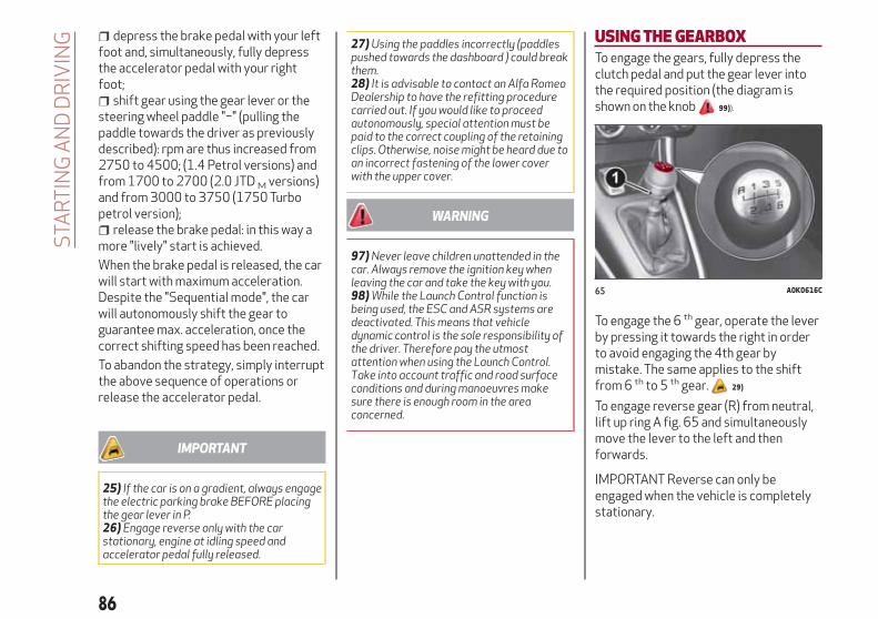
depress the brake pedal with your leftfoot and, simultaneously, fully depressthe accelerator pedal with your rightfoot;
shift gear using the gear lever or thesteering wheel paddle "−" (pulling thepaddle towards the driver as previouslydescribed): rpm are thus increased from2750 to 4500; (1.4 Petrol versions) andfrom 1700 to 2700 (2.0 JTD M versions)and from 3000 to 3750 (1750 Turbopetrol version);
release the brake pedal: in this way amore "lively" start is achieved.
When the brake pedal is released, the carwill start with maximum acceleration.Despite the "Sequential mode", the carwill autonomously shift the gear toguarantee max. acceleration, once thecorrect shifting speed has been reached.
To abandon the strategy, simply interruptthe above sequence of operations orrelease the accelerator pedal.
IMPORTANT
25) If the car is on a gradient, always engagethe electric parking brake BEFORE placingthe gear lever in P.26) Engage reverse only with the carstationary, engine at idling speed andaccelerator pedal fully released.
27)Using the paddles incorrectly (paddlespushed towards the dashboard ) could breakthem.28) It is advisable to contact an Alfa RomeoDealership to have the refitting procedurecarried out. If youwould like to proceedautonomously, special attentionmust bepaid to the correct coupling of the retainingclips. Otherwise, noisemight be heard due toan incorrect fastening of the lower coverwith the upper cover.
WARNING
97)Never leave children unattended in thecar. Always remove the ignition keywhenleaving the car and take the keywith you.98)While the Launch Control function isbeing used, the ESC andASR systems aredeactivated. Thismeans that vehicledynamic control is the sole responsibility ofthe driver. Therefore pay the utmostattentionwhen using the Launch Control.Take into account traffic and road surfaceconditions and duringmanoeuvresmakesure there is enough room in the areaconcerned.
USINGTHEGEARBOXTo engage the gears, fully depress theclutch pedal and put the gear lever intothe required position (the diagram isshown on the knob 99)).
To engage the 6 th gear, operate the leverby pressing it towards the right in orderto avoid engaging the 4th gear bymistake. The same applies to the shiftfrom 6 th to 5 th gear. 29)
To engage reverse gear (R) from neutral,lift up ring A fig. 65 and simultaneouslymove the lever to the left and thenforwards.
IMPORTANT Reverse can only beengaged when the vehicle is completelystationary.
65 A0K0616C
86
STA
RT
ING
AN
DD
RIV
ING

WARNING
99)Press the clutch pedal fully to changegears correctly. It is therefore essential thatthere is nothing under the pedals: make surethemats are lying flat and do not get in theway of the pedals.
IMPORTANT
29)Do not drivewith your hand resting onthe gear lever as the force exerted, even ifslight, could lead over time to prematurewear of the gearbox internal components.
START&STOPSYSTEM
(for versions/markets, where provided)
The Stop/Start system automaticallystops the engine each time the vehicle isstationary and starts it again when thedriver wants to move off.
In this way, the vehicle efficiency isincreased, by reducing consumption,dangerous gas emissions and soundpollution.
OPERATINGMODE
Stopping the engine
With the vehicle stopped, the enginestops with gearbox in neutral and clutchpedal released.
NOTE The engine can only be stoppedautomatically after exceeding about10 km/h, to prevent the engine frombeing repeatedly stopped when driving atwalking pace.
The symbol appears on the displaywhen the engine stops.
Restarting the engine
Press the clutch pedal to restart theengine.
SYSTEMMANUALACTIVATION/DEACTIVATION
To activate/deactivate the systemmanually, press the button located onthe central tunnel fig. 66.
Start&Stop system activation
A message will appear on the displaywhen the Start&Stop system isactivated. In this condition, the LED onthe button is off.
Start&Stop system deactivation
Deactivation of the Start&Stop systemis indicated by the symbol and amessage on the display.
The LED on the button switches onwhen the system is deactivated.
66 A0K0613C
87

MISSED ENGINE STOPPINGCONDITIONS
When the system is active, for a highercomfort and safety, and to reduceemissions, the engine does not stop incertain ambient conditions, engineconditions, with the doors not closed andseat belts unfastened. 30)
ENGINE RESTARTING CONDITIONS
Due to comfort, emission control andsafety reasons, the engine can restartautomatically without any action by thedriver, when the vehicle and the climatecontrol system are in certain conditions,such as:
With gear engaged, automatic enginerestarting is possible only by fullypressing the clutch pedal. The driver isinformed by the displaying of a messageon the display and - for versions/markets,where provided - by the flashing of thesymbol .
SAFETYFUNCTIONS
When the engine is stopped by theStart&Stop system, if the driver releaseshis/her seat belt and opens the driver's orpassenger's door, the engine can berestarted only by the ignition key.
The driver is informed by a buzzer and bythe flashing of the symbol on thedisplay (on some versions, a message isdisplayed as well).
"ENERGYSAVING" FUNCTION(for versions/markets, where provided)
If, following the automatic enginerestarting, the driver does not carry outany action on the vehicle for over3 minutes, the Start&Stop system stopsthe engine definitely, to prevent fuelconsumption. In these cases, the enginecan be restarted only using the ignitionkey.
NOTE In any case, it is possible to keepthe engine running by deactivating theStart&Stop system.
IRREGULAROPERATION
In the event of malfunction, theStop/Start system is deactivated.
The driver is informed of the fault by theflashing of the symbol . Forversions/markets, where provided, awarning message will also appear on thedisplay.
In this case, contact an Alfa RomeoDealership.
VEHICLE INACTIVITY
In the event of vehicle inactivity (or if thebattery is replaced), special attentionmust be paid to the disconnection of thebattery power supply.
100)
IMPORTANT
30) If climate comfort is to be favoured, theStop/Start system can be deactivated, for acontinuous operation of the climate controlsystem.
WARNING
100)When replacing the battery, alwayscontact an Alfa RomeoDealership. Replacethe batterywith one of the same type(HEAVYDUTY) andwith the samespecifications.
88
STA
RT
ING
AN
DD
RIV
ING

CRUISE CONTROL
(for versions/markets, where provided)
This is an electronically controlled drivingassistance device that allows the desiredvehicle speed to be maintained, withouthaving to press the accelerator pedal.This device can be used at a speed above30 km/h on long stretches of dry, straightroads with few variations (e.g.motorways). It is therefore notrecommended to use this device onextra-urban roads with traffic. Do not useit in town.
ACTIVATINGTHEDEVICE
Turn ring 1 fig. 67 to ON.
The device cannot be engaged in 1 st orreverse gear: it is advisable to engage itin 5 th gear or higher.
When travelling downhill with the deviceengaged, the car may slightly exceed thestored speed.
Activation is indicated by the warninglight .
SETTINGTHEDESIRED SPEED
Proceed as follows:turn ring 1 fig. 67 to ON and press the
accelerator to reach the required speed;move the stalk upwards (+) for at least
1 second, then release it: the car speed isnow stored and you can therefore releasethe accelerator.
If needed (when overtaking for instance),you can accelerate simply by pressing theaccelerator; when you release the pedal,the vehicle goes back to the speed storedpreviously.
RESTORINGTHEMEMORISED SPEED
If the device has been disengaged bypressing the brake or clutch pedal, thestored speed can be reset as follows:
accelerate gradually until a speedapproaching the one stored is reached;
engage the gear selected at the timeof speed storing;
press the RES button (2 fig. 67).
INCREASINGTHEMEMORISED SPEED
Once the electronic Cruise Control hasbeen activated, the speed can beincreased by pressing button SET +.
REDUCINGTHEMEMORISED SPEED
Once the electronic Cruise Control hasbeen activated, the speed can be reducedby pressing the button SET -.
DEACTIVATINGTHEDEVICE
The device can be switched off in thefollowing ways:
by turning the ring 1 fig. 67 to the OFFposition;
by switching off the engine;by pressing the brake pedal, the clutch
or the accelerator; in this last case thesystem is not effectively deactivated butthe system gives priority to theacceleration request. The device stillremains active, without the need to pressthe RES button to return to the previousconditions once acceleration isconcluded.
Automatic deactivation
The device is automatically switched offin the following cases:
if the ABS or ESC systems intervene;with the vehicle speed below the set
limit;in the event of system failure.
101)67 A0K0559C
89

WARNING
101)When travelling with the device active,nevermove the gear lever to neutral.102) In case of amalfunction or failure ofthe device, contact an Alfa RomeoDealership.
PARKINGSENSORS
(for versions/markets, where provided)
These are located in the car's frontbumper and rear bumper and theirfunction is to inform the driver, throughan intermittent acoustic signal, about thepresence of obstacles in front of andbehind the car.
ACTIVATION
Version with rear sensors
On the versions with rear sensors, thesystem is activated when the reversegear is engaged.
Version with front and rear sensors
On versions with front sensors and rearsensors, the system is activated whenthe reverse gear is engaged or bypressing the button on the centre console
.
When reverse gear is released, the frontand rear sensors remain activated until aspeed of around 15 km/h is exceeded toallow the parking manoeuvre to becompleted.
The sensors are deactivated by pressingthe button again or when a speed of15 km/h is exceeded: the LED in thebutton is off when the system is notactive.
INDICATIONSONDISPLAY(for versions/markets, where provided)
Versions with rear sensors
On activating the sensors, the image ofthe vehicle with rear distance bars willappear on the "ReconfigurableMultifunction Display".
Versions with front and rear sensors
On activating the sensors, the image ofthe vehicle with front and rear distancebars will appear on the "ReconfigurableMultifunction Display".
Obstacle presence and distanceinformation is therefore provided bothby the buzzer (volume of the acousticwarning cannot be adjusted) and theindication on the display.
If there are several obstacles, the closestone is displayed. On the version withfront and rear sensors, the closestobstacle in the front area and in the reararea is displayed.
ACOUSTIC SIGNAL
The information concerning the presenceand distance of an obstacle from the caris transmitted to the driver by means ofacoustic signals from buzzers installed inthe passenger compartment.
When reverse gear is engaged an
90
STA
RT
ING
AN
DD
RIV
ING

acoustic signal is automatically activatedif there is an obstacle within the range ofoperation.
The acoustic signal:increases as distance between the car
and the obstacle decreases;becomes continuouswhen the
distance between the car and theobstacle is less that 30 cm and stopsimmediately if the distance increases;is constant if the distance is unvaried;
if this situation occurs for the sidesensors, the signal will stop after about3 seconds to avoid, for example,indications in the event of manoeuvresalongside walls.
OPERATIONWITHATRAILER
Parking sensor operation is automaticallyturned off when the trailer electric cableplug is fitted into the car tow hooksocket. 31)
The sensors are automaticallyreactivated when the trailer's cable plugis removed. 103) 104)
IMPORTANTNOTES
During parking manoeuvres, pay theutmost attention to any obstacles thatcould be located above or below thesensors.
Objects set close to the car rear, undercertain circumstances are not detected
and could therefore cause damage to thecar or be damaged.
The following conditions may influencethe performance of the parkingassistance system:
reduced sensor sensitivity and areduction in the parking assistancesystem performance could be due to thepresence on the surface of the sensor of:ice, snow, mud, thick paint
The sensors may detect anon-existent obstacle (echo interference)due to mechanical interference, forexample when washing the car, in rain(strong wind), hail.
The signals sent by the sensors canalso be altered by the presence ofultrasonic systems (e.g. pneumatic brakesystems or pneumatic drills) near thevehicle.
sensor performance can also beinfluenced by the position of the sensors.For example by a change in the ridesetting (caused by the wear of the shockabsorbers, suspension), overloading thecar and carrying out specific tuningoperations that require the car to belowered;
The detection of obstacles at the toppart of the car may not be guaranteedbecause the system detects obstaclesthat could cause an impact with the car inthe bottom part.
IMPORTANT
31) The sensormust be free ofmud, dirt,snow or ice in order for the system towork.Be careful not to scratch or damage thesensorswhile cleaning them. Avoid using dry,rough or hard cloths. The sensorsmust bewashed using cleanwater, with the additionof vehicle shampoo if necessary.When usingspecial washing equipment such as highpressure jets or steam cleaning, clean thesensors very quickly keeping the jetmorethan 10 cmaway.
WARNING
103)Only have the bumpers repainted orany retouches to the paintwork in the area ofthe sensors carried out by anAlfa RomeoDealership. Incorrect paint application couldaffect the operation of the parking sensors.104) Parking and other dangerousmanoeuvres are, however, always thedriver’s responsibility.While carrying outthesemanoeuvres, alwaysmake sure thatno people (especially children) or animals arein the area concerned. The parking sensorsare an aid for the driver, but the drivermustnever allow their attention to lapse duringpotentially dangerousmanoeuvres, eventhose executed at low speeds.
91

TOWINGTRAILERSIMPORTANT NOTES
The car must be provided with atype-approved tow hook and adequateelectric system to tow caravans ortrailers. Installation must be carried outby a specialist.
Install any specific and/or additional doormirrors as specified by the HighwayCode.
Remember that when towing a trailer,steep hills are harder to climb, thebraking spaces increase and overtakingtakes longer depending on the overallweight.
Engage a low gear when driving downhill,rather than constantly using the brake.
The weight of the trailer reduces the loadcapacity of the car by the same amount.Consider the weight at full load, includingaccessories and luggage, to make sureyou do not exceed the maximum towableweight (shown in the registrationdocument).
Do not exceed the speed limits specificto each country you are driving in, in thecase of vehicles towing trailers. In anycase do not exceed 100 km/h.
INSTALLINGATOWHOOKContact an Alfa Romeo Dealership toinstall a tow hook. 105) 106)
WARNING
105) The ABSwith which the car is equippedwill not control the braking systemof thetrailer. Particular caution is thereforerequired on slippery roads.106)Do not, under any circumstances,modify the vehicle's braking system tocontrol the trailer breaking system.Thetowing braking systemmust be completelyindependent of the vehicle's hydraulicsystem.
REFUELLINGTHEVEHICLEStop the engine before refuelling.
PETROL ENGINES
Only use unleaded petrol 95 R.O.N.compliant with the Europeanspecification EN228. The petrol octanerating (RON) must not be lower than 95.In order to prevent damage to thecatalytic converter never introduce eventhe smallest amount of leaded petrol,even in the event of an emergency.
DIESEL ENGINES
Only use diesel fuel compliant withEuropean specification EN590. The useof other products or mixtures maydamage the engine beyond repair andconsequently invalidate the warranty,due to the damage caused.
Operation at low temperatures
If the outside temperature is very low,diesel thickens due to the formation ofparaffin clots with consequent defectiveoperation of the fuel supply system.
In order to avoid these problems,different types of Diesel are distributedaccording to the season: summer type,winter type and arctic type (cold,mountain areas).
If refuelling with diesel whosespecifications are not suitable for theusage temperature, it is advisable to mix
92
STA
RT
ING
AN
DD
RIV
ING

TUTELA DIESEL ART additive in theproportions shown on the container withthe fuel. Pour the additive into the tankbefore the fuel.
When using or parking the car for a longtime in the mountains or cold areas, it isadvisable to refuel using locally availablefuel. In this case, it is also advisable tokeep the tank over 50% full.
LPG ENGINES
The gas filler is located next to the petrolfiller cap. It has a "non return", located inthe filler body itself.
To access the filler 1 fig. 68 open theaccess flap 2.
Observe the following precautions duringthe refuelling operation:
switch off the engine;apply the handbrake;
turn the ignition key to the STOPposition;
do not smoke;hand the special adapter 3 over to the
qualified LPG refuelling personnel.
The adapter 3 is located in a special case.
IMPORTANT Depending on the country,there are different types of adapters forrefuelling pumps. The adapter that comeswith the car is specifically designed forthe country in which the car is sold. If youare in a different country, find out whattype of adapter is used there.
IMPORTANT Only use the adaptersupplied with the vehicle as it is equippedwith a dedicated fuel pre-filter.
REFUELLING CAPACITYTo ensure that you fill the tankcompletely, top up twice after the firstclick of the fuel supply gun. Furthertop-ups could cause faults in the fuelfeeding system.
FUELTANKCAPThe fuel cap is unlocked when the centrallocking system is released andautomatically clocked when the centrallocking system is applied.
Opening
Press flap 2 fig. 69 to release it andaccess fuel tank cap 1. Then press cap1 and rotate it anticlockwise. 107)
The cap is provided with a retentiondevice 4 which attaches it to the flap andprevents it from being lost. Attach thecap to device 3 during refuelling.
How to open the flap in an emergency
In case of emergency, pull the cordfig. 70 on the right-hand side of theluggage compartment to open the fuelflap.
68 A0K0906C
69 A0K0598C
70 A0K0599C
93

Pulling the cord releases the flap lock: theflap can then can be opened by pressingit.
Closing
Release cap 1 from device 3 and insert itin its housing. Then tighten the capclockwise until one or more clicks areheard. Finally, close flap A checking thatit is correctly locked.
The sealing may cause a slight pressureincrease in the tank. A little breathing off,while slackening the cap is absolutelynormal.
WARNING
107)Do not bring naked flames or litcigarettes near to the fuel tank opening: firerisk. Keep your face away from the fuel fillerto prevent breathing in harmful vapours.
94
STA
RT
ING
AN
DD
RIV
ING

A punctured tyre or a burnt-out bulb?At times, a problem may interfere with our journey.
The pages on emergencies can help you to deal with criticalsituations independently and with calm. In an emergency werecommend that you call the freephone number found in theWarranty Booklet. You can also use the universal, national or
international freephone number to find your nearest AuthorisedAlfa Romeo Dealership.
IN AN EMERGENCYHAZARD WARNING LIGHTS . . . . . . . . . . . . . . . . . . . . . . . .96REPLACING A BULB . . . . . . . . . . . . . . . . . . . . . . . . . . . . .96REPLACING AN EXTERIOR BULB . . . . . . . . . . . . . . . . . . . .100REPLACING FUSES . . . . . . . . . . . . . . . . . . . . . . . . . . . .102CHANGING A WHEEL . . . . . . . . . . . . . . . . . . . . . . . . . . .110"Fix&Go Automatic" KIT. . . . . . . . . . . . . . . . . . . . . . . . . .113JUMP STARTING . . . . . . . . . . . . . . . . . . . . . . . . . . . . . .116FUEL CUT-OFF SYSTEM . . . . . . . . . . . . . . . . . . . . . . . . .117TCT TRANSMISSION - KEY REMOVAL . . . . . . . . . . . . . . . . .117TOWING THE VEHICLE . . . . . . . . . . . . . . . . . . . . . . . . . .119

HAZARDWARNING LIGHTS
Operation
Press switch 1 fig. 71 to turn the lightson/off.
Warning lights and come on andthe switch 1 will blink when the lights areon.
Emergency braking
In the event of emergency braking thehazard warning lights switch onautomatically as well as warning lights
and in the instrument panel.
The lights are switched off automaticallywhen the nature of braking changes.
108)
WARNING
108) The use of hazardwarning lights isgoverned by the highway code of the countryyou are driving in: complywith legalrequirements.
REPLACINGABULB32) 109) 110) 111)
GENERAL INSTRUCTIONS
Check that the correspondingcontacts are not oxidised and that thecorresponding fuse is intact beforechanging the bulb. For the location offuses, refer to the paragraph “If a fuseblows” in this chapter.
replace blown bulbs with others of thesame type and power;
after replacing a headlight bulb,always check its alignment;
IMPORTANT When the weather is cold ordamp or after heavy rain or washing, thesurface of headlights or rear lights maysteam up and/or form drops ofcondensation on the inside. This is anatural phenomenon due to thedifference in temperature and humiditybetween the inside and the outside of theglass which does not indicate a fault anddoes not compromise the normaloperation of lighting devices. The mistdisappears quickly when the lights areturned on, starting from the centre of thediffuser, extending progressivelytowards the edges.
71 A0K0622C
96
INA
NE
ME
RG
EN
CY

TYPESOFBULBS
The car has the following bulbs:
All-glass bulb: (type A) these are press-fitted. Pull to extract.
Bayonet bulb: (type B) to remove this type of bulb from its holder, pressthe bulb and turn it anticlockwise.
Cylindrical bulbs: (type C): release them from their contacts to remove.
Halogen bulbs: (type D) release the fastening clip from thecorresponding seat to remove the bulb.
Halogen bulbs: (type E) release the fastening clip from thecorresponding seat to remove the bulb.
97

Light bulbs Type Power Ref. Figure
Front side lights/Daytime running lights (DRL) LED – –
Rear side lights LED – –
Dipped headlights H7 55 W D
Main beams H1 55 W E
Dipped/Main beam headlights (versions with Bi-Xenonheadlights) (for versions/markets, where provided)
F D1S -
Front direction indicators PY24W 24W B
Rear direction indicators R10W 10 W B
Side direction indicators LED – –
Stop LED – –
3rd brake light LED – –
Number plate W5W 5 W A
Fog lights H3 55 W E
Rear fog light H21W 21 W B
Reversing light P21W 21 W B
Front ceiling light C10W 10 W C
Luggage compartment light W5W 5 W A
Glove compartment light C5W 5 W C
IMPORTANT
32)Halogen bulbsmust be handled holding themetallic part only. Touching the transparent part of the bulbwith your fingersmay reduce theintensity of the emitted light and even reduce the lifespan of the bulb. In the event of accidental contact, wipe the bulbwith a clothmoistenedwithalcohol and let the bulb dry.
98
INA
NE
ME
RG
EN
CY

WARNING
109)Modifications or repairs to the electric system that are not carried out properly or do not take the system technical specifications intoaccount can causemalfunctions leading to the risk of fire.110)Halogen bulbs contain pressurised gas, in the case of breakage theymay burst causing glass fragments to be projected outwards.111)Due to the high power supply voltage, gas discharge bulbs (Bi-Xenon) should only be replaced by specialised personnel: danger of death!Contact an Alfa RomeoDealership.
99

REPLACINGANEXTERIORBULB
FRONTLIGHTCLUSTERS
These contain the bulbs for the sidelights/daytime running lights (DRL),dipped beams, main beams and directionindicators. The bulbs are arranged asfollows fig. 72:
1: Dipped headlights
2: Side lights/daytime running lights andmain beam headlights
3: Direction indicators
SIDE LIGHTS/DAYTIMERUNNINGLIGHTS (DRL)These are LEDs. For the replacement,contact an Alfa Romeo Dealership.
MAIN BEAMHEADLIGHTSTo replace the bulb, proceed as follows:
remove the cover 2 fig. 72;remove the connector 3 fig. 73 and
then open the tabs 1 pulling outwards;
extract the bulb 2 and replace it;fit the new lamp, making sure that it is
locked correctly, re-engage the tabs1 and reconnect the connector 3;
finally, refit the cover 2 fig. 72.
DIPPEDHEADLIGHTSTo replace the bulb, proceed as follows:
remove the cover 1 fig. 72;remove the connector 2 fig. 74, press
the tab 1 forward and then release bypushing it towards the inside of the car;
extract the bulb 3 and replace it;fit the new lamp, making sure that it is
locked correctly, secure the tab 1 againand reconnect the connector 2;
finally, refit the cover 1 fig. 72.
DIRECTION INDICATORSFront
To replace the bulb, proceed as follows:turn the cover 3 fig. 72 anticlockwise
by ¼ of a turn;
72 A0K0631C
73 A0K0632C 74 A0K0633C
75 A0K0634C
100
INA
NE
ME
RG
EN
CY

replace the bulb + bulb holderassembly 1 fig. 75.
Side
These are LEDs. For the replacement,contact an Alfa Romeo Dealership.
FRONTFOG LIGHTS
(for versions/markets, where provided)
For replacing these bulbs, contact an AlfaRomeo Dealership.
REAR LIGHTCLUSTERS
These contain the side lights, brakelights, direction indicators (bulbs in fixedlight cluster), reversing light and rear foglight (bulb in light cluster on tailgate).
Removing the fixed light cluster
Proceed as follows:open the boot and unscrew the screw
1 fig. 76 securing the rear light cluster;
extract the light cluster by removing itwith both hands in the direction indicatedby the arrows;
disconnect the electrical connectorand replace the bulb concerned.
SIDE LIGHTS/BRAKE LIGHTSThese are LEDs. For the replacement,contact an Alfa Romeo Dealership.
DIRECTION INDICATORSWith the light cluster removed, to replacethe bulb undo the two screws 1 fig. 77,remove the bulb holder and replace bulb2.
REAR FOG LIGHTS/REVERSINGLIGHTSTo replace the bulbs proceed as follows:
open the luggage compartment andremove the cover 1 fig. 78 using ascrewdriver in the point indicated by anarrow;
remove the connector 3 fig. 79 andextract the bulb holder assembly byreleasing the retaining tab 1 and then byloosening the screw 2;
76 A0K0635C
77 A0K0636C
78 A0K0637C
79 A0K0638AC
101

remove the bulb by pushing it slightlyand turning it anticlockwise (1 = reversinglight bulb; 2 = rear fog light bulb) (seefig. 80);
refit the bulb holder assemblypositioning it correctly, fasten screw2 and then fix it by means of the retainingtab 1. Reconnect connector 3 and finallyreplace cover 1 fig. 78.
IMPORTANT Protect the tip of thescrewdriver with a cloth to preventscratching when removing the cover 1.
THIRDBRAKE LIGHTSThese are LED lights and are located onthe spoiler integrated with the tailgate.For the replacement, contact an AlfaRomeo Dealership.
NUMBERPLATE LIGHTSTo replace the bulbs, proceed as follows:
remove the number plate light units Afig. 81;
turn the bulb holder 2fig. 82 anticlockwise, extract the bulb3 and replace it;
fit the new bulb, making sure it isproperly locked, then put the numberplate light units fig. 81 back in place,making sure they are properly locked.
REPLACING FUSES
GENERAL INFORMATION
Fuses protect the electrical system: theyintervene (blow) in the event of a failureor improper action on the system.
Use the pliers located inside the cover ofthe engine compartment fuse box toremove the fuses (see “Enginecompartment fuse box” for how toremove the cover).
VERSIONSWITH "ALFATCT"AUTOMATIC TRANSMISSION(for versions/markets, where provided)
The Alfa TCT transmission componentsare protected by specific fuses. Contactan Alfa Romeo Dealership if a fuse needsreplacing.
FUSEBOXS
Fuses are grouped together in fuseboxeslocated in the engine compartment, onthe dashboard and inside the boot.
Engine compartment junction box
This is located next to the battery fig. 84:to access the fuses, undo screws 1fig. 83 and remove cover 2.
80 A0K0638BC 81 A0K0905C
82 A0K0640C
102
INA
NE
ME
RG
EN
CY
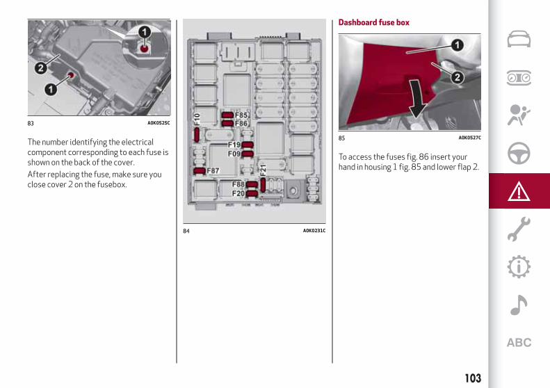
The number identifying the electricalcomponent corresponding to each fuse isshown on the back of the cover.
After replacing the fuse, make sure youclose cover 2 on the fusebox.
Dashboard fuse box
To access the fuses fig. 86 insert yourhand in housing 1 fig. 85 and lower flap 2.
83 A0K0525C
84 A0K0231C
85 A0K0527C
103

Dashboard fuse box (right-hand drivevehicles)
To access the fuses fig. 86 insert yourhand in housing 1 fig. 85 and lower flap 2.
86 A0K0244C
87 A0K0731C
88 A0K0249C
104
INA
NE
ME
RG
EN
CY

Luggage compartment fuse box
The fuse box (fig. 89 ) is located on theleft side of the luggage compartmentunderneath the side cover.
For access, contact an Alfa RomeoDealership.
89 A0K0529C
105

Dashboard fuse boxfig. 86
DEVICE PROTECTED FUSE AMPERE
Right main beam headlight F91 7.5
Left main beam headlight F90 7.5
Right dipped beam headlight (versions with halogen headlights) F12 7.5
Left dipped beam headlight (versions with halogen headlights) F13 7.5
Right dipped beam headlight (versions with Bi-Xenon headlights) F12 15
Left dipped beam headlight (versions with Bi-Xenon headlights) F13 15
Right fog light F93 7.5
Left fog light F92 7.5
Luggage compartment courtesy light/Sun visor courtesy light/Glove compartment courtesylight/Front and rear roof lights
F32 10
Various devices F31 5
Rear electric window (left side) F33 20
Rear electric window (right side) F34 20
+30 F36 10
Various devices F37 7.5
Centralised locking system F38 20
Body Computer power supply F42 5
Two-way windscreen washer pump F43 20
Front electric window (driver side) F47 20
Front electric window (passenger side) F48 20
Various devices F49 5
106
INA
NE
ME
RG
EN
CY

DEVICE PROTECTED FUSE AMPERE
Various devices F50 7.5
Various devices F51 5
+30 F53 7.5
107

Engine compartment junction boxfig. 84
DEVICE PROTECTED FUSE AMPERE
Headlamp washer pump power supply F09 30
Horn F10 15
AC compressor F19 7.5
Heated rear window F20 30
Fuel pump F21 15
Cigar lighter/power socket F85 20
12V boot power socket F86 20
IBS Battery charge status sensor for Start&Stop system F87 5
Door mirror defrosters F88 7.5
108
INA
NE
ME
RG
EN
CY

Luggage compartment fuse boxfig. 89
DEVICE PROTECTED FUSE AMPERE
Left front seat movement F1 15
Right front seat movement F2 15
Electric sunroof F3 15
Front seat heating F5 15
BOSE amplifier + Subwoofer F6 20
IMPORTANT
33)Never replace a fusewithmetal wires or anything else.34) If it is necessary towash the engine compartment, take care not to directly hit the fuse box and thewindowwipermotorswith thewater jet.
WARNING
112) If a fuse blows again, contact an Alfa RomeoDealership.113)Never replace a fusewith another with a higher amp rating; DANGEROFFIRE.114) If a general protective fuse (MAXI-FUSE,MEGA-FUSE,MIDI-FUSE) blows, contact an Alfa RomeoDealership.115)Before replacing a fuse, make sure that the ignition device is at STOP, that the key, if mechanical, has been removed and that all devices areswitched off and/or disconnected.116)Contact an Alfa RomeoDealership if a safety system (airbags, brakes), transmission system (engine, gearbox) or steering systemgeneralprotection fuse blows.
109

CHANGINGAWHEEL
JACK117) 118) 119) 120) 121) 122)
Please note that:the jack weight is 1.76 kg;the jack requires no adjustment;the jack cannot be repaired and in the
event of a fault it must be replaced byanother genuine one;
no tool other than its cranking devicemay be fitted on the jack.
Jack maintenance:prevent any dirt from depositing on
the "worm screw";keep the "worm screw" lubricated;never modify the jack.
Conditions in which not to use the jack:temperature below -40°Con sandy or muddy groundon uneven groundon steep roadsin extreme weather conditions:
thunderstorms, typhoons, hurricanes,blizzards, storms, etc.
in direct contact with the engine or tocarry out repairs under the vehicle
on boats.
To change a wheel, proceed as follows:stop the car in a position that is not
dangerous for oncoming traffic whereyou can change the wheel safely. The
ground must be flat and sufficientlycompact;
switch off the engine, pull up thehandbrake and engage the 1 st gear orreverse. Wear the reflective safety jacket(compulsory by law) before getting out ofthe vehicle;
open the luggage compartment, liftthe mat using the tab provided;
using wrench 1 fig. 90 located in thetool box, loosen the locking device, takethe tool box 2 and place it close to thewheel to be replaced, then take thespace-saver wheel 3;
take the wrench 1 fig. 91 and loosenthe fixing bolts by about one turn. Forversions with alloy rims, shake the car tofacilitate detachment of the rim from thewheel hub;
position the jack under the car, nearthe wheel to be changed. On versionswhere this is fitted, be careful not todamage the plastic aerodynamic guard;
operate the device 1 fig. 92 so as toraise the jack, until the upper part iscorrectly inserted in the side member atthe point indicated by the arrow
fig. 92. The lifting points 3 are shownin fig. 93.
90 A0K0649C
91 A0K0650C
92 A0K0651C
110
INA
NE
ME
RG
EN
CY
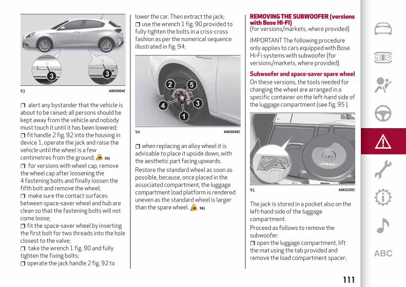
alert any bystander that the vehicle isabout to be raised; all persons should bekept away from the vehicle and nobodymust touch it until it has been lowered;
fit handle 2 fig. 92 into the housing indevice 1, operate the jack and raise thevehicle until the wheel is a fewcentimetres from the ground; 35)
for versions with wheel cap, removethe wheel cap after loosening the4 fastening bolts and finally loosen thefifth bolt and remove the wheel;
make sure the contact surfacesbetween space-saver wheel and hub areclean so that the fastening bolts will notcome loose;
fit the space-saver wheel by insertingthe first bolt for two threads into the holeclosest to the valve;
take the wrench 1 fig. 90 and fullytighten the fixing bolts;
operate the jack handle 2 fig. 92 to
lower the car. Then extract the jack;use the wrench 1 fig. 90 provided to
fully tighten the bolts in a criss-crossfashion as per the numerical sequenceillustrated in fig. 94;
when replacing an alloy wheel it isadvisable to place it upside down, withthe aesthetic part facing upwards.
Restore the standard wheel as soon aspossible, because, once placed in theassociated compartment, the luggagecompartment load platform is rendereduneven as the standard wheel is largerthan the spare wheel. 36)
REMOVINGTHE SUBWOOFER (versionswith Bose HI-FI)(for versions/markets, where provided)
IMPORTANT The following procedureonly applies to cars equipped with BoseHi-Fi systems with subwoofer (forversions/markets, where provided).
Subwoofer and space-saver spare wheel
On these versions, the tools needed forchanging the wheel are arranged in aspecific container on the left-hand side ofthe luggage compartment (see fig. 95 ).
The jack is stored in a pocket also on theleft-hand side of the luggagecompartment.
Proceed as follows to remove thesubwoofer:
open the luggage compartment, liftthe mat using the tab provided andremove the load compartment spacer;
93 A0K0904C
94 A0K0040C
95 A0K0235C
111

unscrew the locking device 1 fig. 96,remove the clip 2 fastening the cable andthen lift the subwoofer;
rest the subwoofer on the side of theluggage compartment and take thespace-saver wheel;
replace the wheel as describedpreviously.
At the end of the operation:reposition the subwoofer correctly
(see indications on the label applied overthe subwoofer itself), so that the word“BOSE” is positioned in the right directionfor reading;
reposition the subwoofer wirecorrectly to avoid pinching it. Then fastenthe clip 2 and fasten the locking device 1.Finally, position the load compartmentspacer fig. 95 correctly and lower themat.
Subwoofer and “Automatic Fix&Go Kit”
Locating the Automatic Fix&Go Kit:open the luggage compartment, lift
the mat using the tab provided;
take the “Automatic Fix&Go kit”located on the left-hand side of theluggage compartment (see fig. 97 );
inflate the tyre (see paragraph entitled“Fix&Go Automatic Kit”).
IMPORTANT If you need to remove thesubwoofer, follow the indications shownon the adhesive label fig. 97 on thesubwoofer itself to reposition itcorrectly.
WARNING
117) The space-saver wheel is specific foryour car. Do not use it on cars of differentmodels. Do not use space-saver wheels ofdifferentmodels on your car. Thespace-saver wheelmust only be used in theevent of an emergency. Never use it formorethan strictly necessary and never exceed80 km/h. On the space-saver wheel there isan orange label, summarising themainwarnings regarding space-saver wheelusage restrictions. Never remove or coverthe label. Never apply any hub cap to thespace-saver wheel.118)Alert other drivers that the car isstationary in compliancewith localregulations: hazardwarning lights, warningtriangle, etc. Any passengers on boardshould leave the car, especially if it is heavilyladen. Passengers should stay away fromon-coming traffic while thewheel is beingchanged. On hills or uneven roads, usechocks or appropriate objects to block thewheels of the vehicle.
96 A0K0654C
97 A0K0178C
112
INA
NE
ME
RG
EN
CY

119) The vehicle's driving characteristicswill bemodifiedwith the space-saver wheelfitted. Avoid violent acceleration andbraking, abrupt steering and fast cornering.The overall duration of the space-saverwheel is about 3000 km, after which therelevant tyremust be replacedwith anotherone of the same type. Never install atraditional tyre on a rim designed to be usedas a space-saver wheel. Have thewheelrepaired and refitted as soon as possible.Using two ormore space-saver wheels at thesame time is forbidden. Do not apply greaseto the bolt threads before fitting: they couldcome unscrewed.120) The jackmay be used to replacewheels only on the car that it comeswith orother cars of the samemodel. Never use thejack for other purposes, such as lifting othervehiclemodels. Never use it for repairoperations under the vehicle. Incorrectpositioning of the jackmay cause the vehicleto fall. Do not use the jack for loads higherthan the one shown on its label. Never installsnow chains on the space-saver wheel; if afront tyre (drivingwheel) is punctured andyou need to use snow chains, use a standardwheel from the rear axle and install thespace-saver wheel on the rear axle. In thisway, with two normal front drivewheels, it ispossible to use snow chains.121) Incorrectly fitting thewheel capmaycause it to fall off when the car is inmotion.Never tamperwith the inflation valve. Neverintroduce tools of any kind between rim andtyre. Regularly check the inflation pressureof the tyres and space-saver wheel (seechapter "Technical specifications").
122) The jack is a tool developed anddesigned only for changing awheel, if a tyregets punctured or damaged, on the vehiclewithwhich it is supplied or on other vehiclesof the samemodel. Any other use, e.g. to jackup other vehiclemodels or different things,is strictly prohibited. Never use formaintenance or repair activities under thecar or to exchange the summer/winterwheels and vice versa. Never go under theraised vehicle. Should it be necessary towork under the vehicle, contact an AlfaRomeoDealership. Incorrect positioning ofthe jackmay cause the raised vehicle to fall:use only in the positions indicated. Do notuse the jack for loads higher than the oneshown on its label. Never start the enginewith vehicle raised. If the vehicle is raisedmore than necessary, everything canbecomemore unstable, with the risk of thevehicle dropping violently. Thus, lift thevehicle only as needed in order to access thesparewheel.
IMPORTANT
35)When turning the jack handlemake surethat it can turn freely without scraping yourhand against the ground. Themovingcomponents of the jack ("worm screw" andjoints) can also cause injuries: avoid touchingthem. If you come into contact withlubricating grease, clean yourselfthoroughly.36)Contact an Alfa RomeoDealership assoon as possible to have the correcttightening of thewheel bolts checked.
"Fix&GoAutomatic" KIT
37) 38)
This is located in the luggagecompartment (the kit container may varyaccording to the version).
The kit also contains a screwdriver and atow hook.
The kit also contains:bottle 4 fig. 98 containing sealant and
fitted with: filling tube 1 and adhesivelabel 3 with the wording “Max. 80 km/h”to be placed in a clearly visible position(e.g. on the dashboard) after repairing thetyre;
compressor 2 complete with pressuregauge and connectors;
an information leaflet, providinginstructions for using the kit correctly.
98 A0K0516C
113
123)

This booklet should be given to thepersons charged with handling the tyretreated with this kit;
a pair of gloves located in the sidecompartment of the compressor;
adaptors for inflating differentelements.
TYREREPAIRINGANDPRESSURERESTORING PROCEDURE
Proceed as follows:place the vehicle in a safe and suitable
area, engaging the parking brake. Takethe kit from the specific compartment;
remove the adhesive speed label 3fig. 98 and apply it to the dashboard in avisible position. Wear the protectivegloves provided;
remove the cap from the valve of thepunctured tyre and connect and firmlytighten the transparent tube of thesealing fluid 1 fig. 99 and tighten nut 2 onthe tyre valve;
make sure that the switch for thecompressor is in position0 (off), start theengine, open the rear hatch and insert theplug in the into the luggage compartmentpower socket or on central tunnel andstart the engine. Switch on thecompressor by turning the switch toposition I (on);
inflate the tyre to the pressureindicated in the “Wheels” paragraph in the“Technical data” chapter;
if after five minutes pressure is not atleast 1.8 bar/26 psi, turn off the thecompressor and disconnect it from thevalve and power socket, replace the cap,then move the vehicle forwards byapprox. ten metres in order to distributethe sealing fluid inside the tyre evenly;Stop the vehicle safely and repeat theoperation above until the requiredpressure is reached;
if after this operation you still cannotreach at least 1.8 bar/26 psi after5 minutes from switching on thecompressor, THE TYRE IS TOODAMAGED TO BE REPAIRED. Removeand place the kit in the specificcompartment and contact an Alfa RomeoDealership;
if the required pressure is reached,restart driving. Do not exceed 80 km/h.Avoid sudden acceleration or braking.After driving for about 8 km / 5 miles,place the vehicle in a safe and suitable
area, engaging the parking brake. Pick upthe kit, ensure the on-off button is in0position, insert the electrical connector inthe vehicle 12V socket. Remove the capfrom the valve of repaired tyre,disconnect and pull out the black inflationtube, connect it to the valve and lock itwith the lever. Check the tyre pressure onthe pressure gauge.
if the pressure indicated is lower than1.8 bar / 26 psi, the TYRE IS TOODAMAGED AND CANNOT BE REPAIRED.Remove and place the kit in the specificcompartment and contact an Alfa RomeoDealership;
if the pressure indicated is equal to orhigher than 1.8 bar/26 psi, switch on thecompressor and inflate to the requiredpressure. Disconnect and replace the kitin the specific compartment. Drivecarefully to the nearest Alfa RomeoDealership as soon as possible.
99 A0K0518C
114
INA
NE
ME
RG
EN
CY

CHECKINGANDRESTORINGTYREPRESSURE
The compressor can also be used tocheck and if necessary top up the tyrepressure.
Disconnect and pull out the blackinflation tube 1 fig. 100, connect and tothe tyre valve and lock in position withthe lever.
With the same procedure it is possible toinflate bicycle tyres and balloons. The kitshould be used by adults and cannot beused by children.
CARTRIDGEREPLACEMENT
Only use Fix&Go original cartridgeswhich can be purchased at an Alfa RomeoDealership.
To remove the cartridge, disengage thecoupling of the black inflation tube,rotate the cartridge anticlockwise and
then lift it; insert the new cartridge,rotate it clockwise to end of travelposition, insert the coupling of the blackinflation tube blocking it with the stalkand then rewind the tube in thecompressor site.
IMPORTANT
37)Show the package and the label to thepersonnel chargedwith handling the tyretreatedwith the tyre repair kit.38) Fix&Go provides a temporary repair,therefore the tyremust be examined andrepaired by a specialist as soon as possible.The sealing fluid is effective at temperaturesbetween -40°C and +50°C. It is possible torepair tyreswhich have been damaged ontread up to a diameter of 4mm; however,tyres damaged on their side cannot berepaired. Before using Fix&Go kit, ensurethat the tyre isn't excessively damaged andthat the rim is in good condition, otherwisedo not use it and contact an Alfa RomeoDealership. Do not remove foreign bodiesfrom the tyre. Do not let the compressorturned on formore than 20 consecutiveminutes - overheating hazard.
WARNING
123) The information required by theapplicable regulation is indicated on theFix&Go kit package label. Compliancewiththe indications on the label is an essentialcondition to ensure the safety and theeffectiveness of the Fix&Go kit. Carefullyread the label before use, avoid improperuse. Fix&Go is subject to expiration andmust be replaced periodically. The kit shouldbe used by adults and cannot be used bychildren.
100 A0K0521C
115

JUMPSTARTING
STARTINGTHE ENGINEIf the icon stays on constantly on theinstrument panel, contact the AlfaRomeo Dealership immediately.
JUMPSTARTINGIf the battery is flat, start the engineusing an auxiliary battery with the samecapacity or a little higher than the flatone. 39) 40) 124)
Proceed as follows to start the vehicle:connect the positive terminal (+)
fig. 101 of the auxiliary battery only tothe point indicated on the car battery(writing "OK") and nowhere else;
with a second lead, connect thenegative terminal ( − ) of the auxiliarybattery to an earthing point on theengine or the gearbox/transmission ofthe car to be started;
start the engine; when the engine hasbeen started, remove the leads reversingthe order above.
If after a few attempts the engine doesnot start, contact the Alfa RomeoDealership.
JUMPSTARTING
(For versions with Start&Stop system)
When jump starting, never connect thenegative lead (–) of the auxiliary batteryto the negative pole 1 fig. 102 of the carbattery, but rather to an engine/gearboxearth point. 125)
BUMPSTARTINGNever, under any circumstances, jumpstart the engine by pushing, towing orcoasting downhill.
IMPORTANT
39)Never connect the negative terminals ofthe two batteries directly! If the auxiliarybattery is installed on another car, preventaccidental contact betweenmetallic parts ofthe two cars.40)Never use a fast battery-charger tostart the engine as this could damage theelectronic systems of your vehicle,particularly the ignition and engine fuelsupply control units.
WARNING
124) This starting proceduremust beperformed by expert personnel becauseincorrect actions could cause electricaldischarge of considerable intensity.Furthermore, battery fluid is poisonous andcorrosive: avoid contact with skin and eyes.Keep naked flames and lighted cigarettesaway from the battery and do not causesparks.125)Before opening the bonnet, make surethat the engine is off and that the ignitionkey is in the STOPposition. Please follow theinstructions on the decal near the frontcrossmember.We recommend that youremove the key from the ignition if otherpeople remain in the vehicle. The vehicleshould always be left after the key has beenremoved or turned to the STOPposition.During refuelling, make sure that the engineis off (and that the ignition key is in the STOPposition).
101 A0K0247C
102 A0K0755C
116
INA
NE
ME
RG
EN
CY

FUEL CUT-OFF SYSTEM
Operation
This intervenes in the case of an impactcausing:
the fuel supply cut-off with the engineconsequently switching off;
the automatic unlocking of the doors;the switching on of the interior lights.
The intervention of the system isindicated by a message shown on thedisplay.
Carefully check the vehicle for fuel leaks,for instance in the engine compartment,under the vehicle or near the tank area.
126)
After a collision, turn the ignition key toSTOP to prevent the battery fromrunning down.
To restore the correct operation of thecar, proceed as follows:
turn the ignition key to the MARposition;
activate the right direction indicator;deactivate the right direction
indicator;activate the left direction indicator;deactivate the left direction indicator;activate the right direction indicator;deactivate the right direction
indicator;activate the left direction indicator;deactivate the left direction indicator;
ignition key turned to the OFFposition;
turn the ignition key to the MAR-ONposition.
WARNING
126) If, after an impact, you smell fuel ornotice leaks from the fuel system, do notreactivate the system to avoid the risk offire.
TCTTRANSMISSION - KEYREMOVALThe ignition key can be removed only ifthe gear lever is in position P (Park).
If the battery is flat and the ignition key isengaged, the latter is locked in position.
To remove the key manually, proceed asfollows:
apply the handbrake;dashboard fuses (to remove, insert
your hand in housing 1 fig. 103 and lowerflap 2);
using the Allen key provided (seefig. 104) unscrew the two top screws 2fig. 105 securing cover 1;
103 A0K0527C
117

unlock the steering wheel adjustmentlever 1 fig. 106;
pull the steering wheel towards youuntil it is in the end of travel position,then lock it by operating lever 1;
using the Allen key, undo the two lowerscrews 1 fig. 107 securing the cover;
remove the trim 1 fig. 108 for theupper cover;
remove the left side trim 1 fig. 109 forthe cover;
remove the lower cover 1fig. 110detaching the clips fig. 111 from theupper cover;
104 A0K0713C
105 A0K0711C
106 A0K0710C
107 A0K0732C
108 A0K0733C
109 A0K0734C
118
INA
NE
ME
RG
EN
CY

pull tab 1 fig. 112 downwards usingone hand and with the other one removethe key, sliding it outwards;
once the key is removed, refit thesteering column covers, the left side trimfor the cover and the dashboard fuse boxflap, ensuring that they are locked inplace. 41)
IMPORTANT
41) It is advisable to contact an Alfa RomeoDealership to have the refitting procedurecarried out. If youwould like to proceedautonomously, special attentionmust bepaid to the correct coupling of the retainingclips. Otherwise, noisemight be heard due toan incorrect fastening of the lower coverwith the upper cover.
TOWINGTHEVEHICLEThe tow hook provided with the car islocated in the tool box in the luggagecompartment.
ATTACHINGTHETOWRING127) 128) 129)
Towing from the front
Unseat cap 1 using a screwdriver orsimilar tool in the lower slot. Take carenot to damage the paint. Take tow hook2 from its housing in the tool support andscrew it in fully on the threaded pin(fig. 113 ).
Towing from the rear
Versions other than "VELOCE" andwithout "Pack sport": unseat cap 1 using ascrewdriver or similar tool in the upperslot. Take care not to damage the paint.Take tow hook 2 from its housing in thetool support and screw it in fully on the
110 A0K0735AC
111 A0K0735BC
112 A0K0712BC
113 A0K0623C
119

threaded pin (fig. 114 ).
"VELOCE" versions or versions with"Pack sport": detach plug 1 by pressingon the upper part, take tow hook 2 fromits housing in the tool support and screwit in fully on the threaded pin (fig. 114 ).
WARNING
127) For versions with keywithout remotecontrol, before towing, turn the ignition keytoMARand then to STOPwithout removingit. The steering columnwill automaticallylockwhen the key is removed and thewheelscannot be steered. Also check that thegearbox is in neutral (on versions equippedwith automatic transmission, check that thegear lever is in N position). For versionswithelectronic key, move the ignition device toMARand then to STOP, without opening thedoor.
128) The brake servo and theelectromechanical power steeringwill notworkwhile the vehicle is being towed. Youwill therefore need to applymore force onthe brake pedal and steeringwheel. Do notuse flexible ropeswhen towing, and avoidjerkymovements. During towing, make surethat the trailer hitch does not damage anycomponents it is touching.When towing thecar, youmust complywith all specific trafficregulations and adopt an appropriatedriving behaviour. Do not start the enginewhile towing the car. Before tightening thering, clean the threaded housing thoroughly.Make sure that the ring is fully screwed intothe housing before towing the car.129) The front and rear tow hooks should beused only for emergencies on the road. Youare allowed to tow the vehicle for shortdistances using an appropriate device inaccordancewith the highway code (a rigidbar), tomove the vehicle on the road inreadiness for towing or transport via abreakdown vehicle. Tow hooksMUSTNOTbeused to tow vehicles off the road orwherethere are obstacles and/or for towingoperations using cables or other non-rigiddevices. In compliancewith the aboveconditions, towingmust take placewith thetwo vehicles (one towing, the other towed)aligned asmuch as possible along the samecentre line.
114 A0K0898C
120
INA
NE
ME
RG
EN
CY

Correct maintenance permits the performance of the car to bemaintained over time, as well as limited running costs and
safeguarding the efficiency of the safety systems.This chapter explains how.
SERVICINGANDMAINTENANCESCHEDULED SERVICING . . . . . . . . . . . . . . . . . . . . . . . . .122SCHEDULED MAINTENANCE PLAN . . . . . . . . . . . . . . . . . .123PERIODIC CHECKS . . . . . . . . . . . . . . . . . . . . . . . . . . . .132DEMANDING USE OF THE CAR . . . . . . . . . . . . . . . . . . . . .132CHECKING LEVELS . . . . . . . . . . . . . . . . . . . . . . . . . . . .133BATTERY RECHARGING . . . . . . . . . . . . . . . . . . . . . . . . .138AIR CLEANER/POLLEN FILTER/DIESEL FILTER . . . . . . . . . . .139NOZZLES . . . . . . . . . . . . . . . . . . . . . . . . . . . . . . . . . .139HEADLIGHT WASHERS . . . . . . . . . . . . . . . . . . . . . . . . . .140BATTERY . . . . . . . . . . . . . . . . . . . . . . . . . . . . . . . . . .140LIFTING THE VEHICLE . . . . . . . . . . . . . . . . . . . . . . . . . .142BODYWORK. . . . . . . . . . . . . . . . . . . . . . . . . . . . . . . . .142INTERIOR . . . . . . . . . . . . . . . . . . . . . . . . . . . . . . . . . .143

SCHEDULEDSERVICINGCorrect servicing is crucial forguaranteeing a long life for the vehicleunder the best conditions.
For this reason, Alfa Romeo has planneda series of checks and services at fixeddistance intervals and, forversions/markets, where provided, atfixed time intervals, as described in theScheduled Servicing Plan.
Regardless of the above, it is alwaysnecessary to carefully follow theinstructions in the Scheduled ServicingPlan (e.g. periodically check level ofliquids, tyre pressure, etc.).
Scheduled Servicing is offered by all AlfaRomeo Dealerships according to fixedtime or kilometres/miles intervals. If,during each operation, in addition to theones scheduled, the need arises forfurther replacements or repairs, thesemay be carried out with the owner'sexplicit agreement only. If your vehicle isused frequently for towing, the intervalbetween one service operation and thenext should be reduced.
IMPORTANTNOTES
Scheduled Servicing interventions areset out by the Manufacturer. Failure tohave them carried out may invalidate thewarranty.
It is advisable to inform the Alfa Romeo
Dealership of any small operatingirregularities without waiting for the nextservice.
122
SE
RV
ICIN
GA
ND
MA
INT
EN
AN
CE

SCHEDULEDMAINTENANCE PLAN
PETROLVERSIONS
The checks listed in the Scheduled Servicing Plan, after reaching 120,000 km/8 years, must be cyclically repeated starting from thefirst interval, thus following the same intervals as before.
Thousands of miles 9 18 27 36 45 54 63 72 81 90
Thousands of kilometres 15 30 45 60 75 90 105 120 135 150
Years 1 2 3 4 5 6 7 8 9 10
Check tyre condition/wear and adjustpressure, if necessary; check thecondition/expiry date of the “Fix&GoAutomatic” repair kit (forversions/markets, where provided)
Check operation of lighting system(headlights, direction indicators,hazard warning lights, boot,passenger compartment, glovecompartment, instrument panelwarning lights, etc.)
Check and, if necessary, top up fluidlevels (1)
Check exhaust emissions/smokiness
(1) Always only use the liquids shown in the handbook for topping up after having checked that the system is not damaged.
123

Thousands of miles 9 18 27 36 45 54 63 72 81 90
Thousands of kilometres 15 30 45 60 75 90 105 120 135 150
Years 1 2 3 4 5 6 7 8 9 10
Use the diagnosis socket to checksupply/engine management systemsoperation, emissions and, forversions/markets, where provided,engine oil degradation
Visually inspect conditions of:exterior bodywork, underbodyprotection, pipes and hoses (exhaust,fuel system, brakes), rubber elements(gaiters, sleeves, bushes, etc.)
Visually inspect condition of: LPGpipes and connectors, LPG tankfastening (1.4 Turbo Petrol/LPG120 HP version)
Check fuel system operation andparameters using self-diagnosissocket (1.4 Turbo Petrol/LGP 120 HPversion)
Check windscreen/rear window wiperblade position/wear
Check operation of the windscreenwiper/washer system and adjust jets,if necessary
124
SE
RV
ICIN
GA
ND
MA
INT
EN
AN
CE

Thousands of miles 9 18 27 36 45 54 63 72 81 90
Thousands of kilometres 15 30 45 60 75 90 105 120 135 150
Years 1 2 3 4 5 6 7 8 9 10
Check cleanliness of bonnet andluggage compartment locks,cleanliness and lubrication of linkage
Check handbrake lever travel andadjust, if necessary
Visually inspect conditions and wearof front disc brake pads andoperation of pad wear indicator
Visually inspect condition and wear ofrear disc brake pads and operation ofpad wear indicator (forversions/markets, where provided)
Visual inspect condition and checktension of accessory drive belt(s) (forversions without automatic tensioneronly)
Visually inspect conditions of toothedtiming drive belt
Check and, if necessary, top up theAlfa TCT gearbox control oil level (forversions/markets, where provided)(2)
(2) Check to be carried out every year for cars on the road in countries with particularly severe climates (cold countries).
125

Thousands of miles 9 18 27 36 45 54 63 72 81 90
Thousands of kilometres 15 30 45 60 75 90 105 120 135 150
Years 1 2 3 4 5 6 7 8 9 10
Change engine oil and replace oil filter(1.4 Turbo Petrol and 1.4 TurboMultiAir versions)(3) (o) (●)
Change engine oil and replace oil filter(1750 Turbo Petrol versions)
(4)
Replace spark plugs (1.4 Turbo Petroland 1.4 Turbo MultiAir versions)(5)
Replace spark plugs (1750 TurboPetrol versions)
Replace accessory drive belt/s (6)
Replace the toothed timing drive belt (6)
(3) If the car's annual mileage is less than 10,000 km, the engine oil and filter must be replaced every year.(o) Recommended operations(●) Mandatory operations(4) The actual interval for changing engine oil and replacing the engine oil filter depends on the vehicle usage conditions and is signalled by the
warning light or message in the instrument panel. Anyway, it must never exceed 1 year.(5) For 1.4 Turbo Petrol and 1.4 Turbo MultiAir versions, to guarantee correct operation and prevent serious damage to the engine, it is essential to
proceed as follows: only use spark plugs specifically certified for these engines; all spark plugs should be of the same type and brand (see the“Engine” paragraph in the “Technical specifications” section); strictly comply with the replacement intervals in the Scheduled Servicing Plan. It isadvisable to contact an Alfa Romeo Dealership for spark plug replacement.
(6) Areas that are not dusty: recommended maximum mileage 120,000 km. The belt must be replaced every 6 years, regardless of distance travelled.Dusty areas and/or demanding use of the car (cold climates, town use, long periods of idling): advised maximum mileage 60,000 km. The belt mustbe replaced every 4 years, regardless of distance travelled.
126
SE
RV
ICIN
GA
ND
MA
INT
EN
AN
CE

Thousands of miles 9 18 27 36 45 54 63 72 81 90
Thousands of kilometres 15 30 45 60 75 90 105 120 135 150
Years 1 2 3 4 5 6 7 8 9 10
Replace air cleaner cartridge (7)
Replace filter inside the pressureregulator (1.4 Turbo Petrol/LPG120 HP version)
Replace paper filter (LPG in gaseousstate) (1.4 Turbo Petrol/LPG 120 HPversion)
Change the brake fluid (8)
Replace the passenger compartmentcleaner (7) (o) (●)
(7) If the vehicle is used in dusty areas, this cleaner must be replaced every 15,000 km.(8) The brake fluid replacement has to be done every two years, irrespective of the mileage.(o) Recommended operations(●) Mandatory operations
127

DIESELVERSIONS
The checks listed in the Scheduled Servicing Plan, after reaching 120,000 km/6 years, must be cyclically repeated starting from thefirst interval, thus following the same intervals as before.
Thousands of miles 12 24 36 48 60 72 84 96 108 120
Thousands of kilometres 20 40 60 80 100 120 140 160 180 200
Years 1 2 3 4 5 6 7 8 9 10
Check tyre condition/wear and adjustpressure, if necessary; check thecondition/expiry date of the “Fix&GoAutomatic” repair kit (for versions/markets,where provided)
Check operation of lighting system(headlights, direction indicators, hazardwarning lights, boot, passenger compartment,glove compartment, instrument panelwarning lights, etc.)
Check and, if necessary, top up fluid levels(1)
Check exhaust emissions/smokiness
Use the diagnosis socket to checksupply/engine management systemsoperation, emissions and, for versions/markets, where provided, engine oildegradation
(1) Always only use the liquids shown in the handbook for topping up after having checked that the system is not damaged.
128
SE
RV
ICIN
GA
ND
MA
INT
EN
AN
CE

Thousands of miles 12 24 36 48 60 72 84 96 108 120
Thousands of kilometres 20 40 60 80 100 120 140 160 180 200
Years 1 2 3 4 5 6 7 8 9 10
Visually inspect conditions of: exteriorbodywork, underbody protection, pipes andhoses (exhaust, fuel system, brakes), rubberelements (gaiters, sleeves, bushes, etc.)
Check windscreen/rear window wiper bladeposition/wear
Check operation of the windscreenwiper/washer system and adjust jets, ifnecessary
Check cleanliness of bonnet and luggagecompartment locks, cleanliness andlubrication of linkage
Check handbrake lever travel and adjust, ifnecessary
Visually inspect conditions and wear of frontdisc brake pads and operation of pad wearindicator
Visually inspect condition and wear of reardisc brake pads and operation of pad wearindicator (for versions/markets, whereprovided)
Visual inspect condition and check tension ofaccessory drive belt(s) (for versions withoutautomatic tensioner only)
129

Thousands of miles 12 24 36 48 60 72 84 96 108 120
Thousands of kilometres 20 40 60 80 100 120 140 160 180 200
Years 1 2 3 4 5 6 7 8 9 10
Check and, if necessary, top up the Alfa TCTgearbox control oil level (for versions/markets, where provided)(2)
Change engine oil and replace oil filter (3)
Replace accessory drive belt/s (4)
Replace the toothed timing drive belt (4)
Replace fuel filter cartridge(5)
Replace air cleaner cartridge(6)
Change the brake fluid (7)
(2) Check to be carried out every year for cars on the road in countries with particularly severe climates (cold countries).(3) The actual interval for changing engine oil and replacing the engine oil filter depends on the vehicle usage conditions and is signalled by the
warning light or message in the instrument panel. In any case, it must never exceed 2 years. If the vehicle is mainly used in towns and cities, changethe engine oil and filter every year.
(4) Areas that are not dusty: recommended maximum mileage 120,000 km. The belt must be replaced every 6 years, regardless of distance travelled.Dusty areas and/or demanding use of the car (cold climates, town use, long periods of idling): advised maximum mileage 60,000 km. The belt mustbe replaced every 4 years, regardless of distance travelled.
(5) If the vehicle runs on fuel with quality below the relevant European specification, this filter must be replaced every 20,000 km(6) If the vehicle is used in dusty areas, this cleaner must be replaced every 20,000 km.(7) The brake fluid replacement has to be done every two years, irrespective of the mileage.
130
SE
RV
ICIN
GA
ND
MA
INT
EN
AN
CE

Thousands of miles 12 24 36 48 60 72 84 96 108 120
Thousands of kilometres 20 40 60 80 100 120 140 160 180 200
Years 1 2 3 4 5 6 7 8 9 10
Replace the passenger compartmentcleaner(6) (o) (●)
(6) If the vehicle is used in dusty areas, this cleaner must be replaced every 20,000 km.(o) Recommended operations(●) Mandatory operations
131

PERIODIC CHECKSEvery 1,000 km or before long journeys,check and, if necessary, top up thefollowing:
engine coolant, brake fluid andwindscreen washer fluid level;
tyre inflation pressure and condition;operation of lighting system
(headlights, direction indicators, hazardwarning lights, etc.);
operation of screen wash/wipe systemand positioning/wear of windscreen/rearscreen wiper blades
Check and top up, if required, the engineoil level every 3,000 km.
IMPORTANT To find out the correct oilquantity, always check using the dipstick.Carry out the check with the vehicleparked on level ground.
DEMANDINGUSEOFTHE CARIf the vehicle is used mainly under one ofthe following conditions:
towing a trailer or caravan;dusty roads;short, repeated journeys (less than
7-8 km) at sub-zero outsidetemperatures;
engine often idling or driving longdistances at low speeds or long periodsof inactivity;
the following checks must be carried outmore often than indicated in theScheduled Servicing Plan:
check front disc brake pad conditionand wear;
check cleanliness of bonnet andluggage compartment locks, cleanlinessand lubrication of linkage;
visually inspect condition of: engine,gearbox, transmission, pipes and hoses(exhaust - fuel system - brakes) andrubber elements (boots - sleeves - bushes- etc.);
check battery charge and battery fluidlevel (electrolyte);
visually inspect conditions of theaccessory drive belts;
check and, if necessary, change engineoil and replace oil filter;
check and, if necessary, replace pollenfilter;
check and, if necessary, replace aircleaner.
132
SE
RV
ICIN
GA
ND
MA
INT
EN
AN
CE

CHECKING LEVELS42)
130) 131)
1.4Turbo Petrol versions
115 A0K0655C
133

1.4TurboMultiAir versions
116 A0K0656C
134
SE
RV
ICIN
GA
ND
MA
INT
EN
AN
CE

1750Turbo Petrol versions
117 A0K0657C
135

Diesel versions
118 A0K0658C
136
SE
RV
ICIN
GA
ND
MA
INT
EN
AN
CE
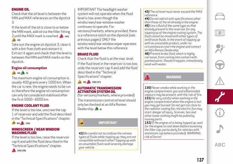
ENGINEOILCheck that the oil level is between theMIN and MAX references on the dipstick3.
If the level of the oil is close to or belowthe MIN mark, add oil via the filler fitting2 until the MAX mark is reached. 132)
43)
Take out the engine oil dipstick 3, clean itwith a lint-free cloth and reinsert it.Extract it again and check that the level isbetween the MIN and MAX marks on thedipstick.
Engine oil consumption
44) 3)
The maximum engine oil consumption isusually 400 grams every 1000 km. Whenthe car is new, the engine needs to be runin; therefore the engine oil consumptioncan only be considered stabilised afterthe first 5000 - 6000 km.
ENGINE COOLANTFLUIDIf the level is too low, unscrew the cap1 of reservoir and add the fluid describedin the "Technical Specifications" chapter.
45) 133)
WINDSCREEN /REARWINDOWWASHING FLUIDIf the level is too low, raise the reservoircap 6 and add the fluid described in the"Technical Specifications" chapter.
134) 135)
IMPORTANT The headlight washersystem will not operate when the fluidlevel is low, even though thewindscreen/rear window washercontinues to operate. Forversions/markets, where provided, thereis a reference notch on the dipstick (seeprevious pages): ONLY thewindscreen/rear window wiper operateswith the level below this reference.
BRAKE FLUIDCheck that the fluid is at the max. level.
If the fluid level in the reservoir is too low,undo the reservoir cap 4 and add the fluiddescribed in the "TechnicalSpecifications" chapter.
46) 136) 137)
AUTOMATICTRANSMISSIONACTIVATIONSYSTEMOIL(for versions/markets, where provided)
The transmission control oil level shouldonly be checked at an Alfa RomeoDealership. 4)
IMPORTANT
42)Be careful not to confuse the varioustypes of fluidswhile topping up: they are notcompatible with each other! Topping upwithan unsuitable fluid could severely damageyour vehicle.
43) The oil level must never exceed theMAXreference.44)Do not add oil with specifications otherthan those of the oil already in the engine.45)Use a fluid of the same type as thatalready present in the reservoir for anytopping up of the engine cooling system.Thefluid cannot bemixedwith other types ofantifreeze fluids. In the event of topping upwith an unsuitable product, under nocircumstances start the engine and contactan Alfa RomeoDealership.46)Prevent brake fluid, which is highlycorrosive, from coming into contact withpainted parts. Should it happen, immediatelywashwithwater.
WARNING
130)Never smokewhile working in theengine compartment: gas and inflammablevapoursmay be present, with the risk of fire.131)Be very careful whenworking in theengine compartmentwhen the engine is hot:youmay get burned. Do not get too close tothe radiator cooling fan: the electric fanmaystart; danger of injury. Scarves, ties andother loose clothingmight be pulled bymoving parts.132) If the engine oil is being topped up, waitfor the engine to cool down before looseningthe filler cap, particularly for vehicleswithaluminium cap (where provided).WARNING:risk of burns!
137

133) The cooling system is pressurised. Ifnecessary, only replace the plugwithanother original or the operation of thesystemmay be adversely affected. Do notremove the reservoir plugwhen the engine ishot: you risk scalding yourself.134)Do not travel with thewindscreenwasher fluid reservoir empty: thewindscreenwasher is essential forimproving visibility. Repeated operation ofthe systemwithout fluid could damage orcause rapid deterioration of some systemcomponents.135)Some commercial additives forwindscreenwasher fluid are flammable. Theengine compartment contains hotcomponentswhichmay start a fire.136)Brake fluid is poisonous and highlycorrosive. In the event of accidental contact,immediately wash the affected partswithwater andmild soap. Then rinse thoroughly.Call a doctor immediately if swallowed.137) The symbol , on the brake fluidcontainer indicates if a brake fluid issynthetic ormineral-based. Use ofmineraltype fluidswill damage the special rubberseals of the braking systembeyond repair.
IMPORTANT
3)Used engine oil and oil filters containsubstanceswhich are harmful to theenvironment. To change the oil and filters, weadvise you to contact an Alfa RomeoDealership.4)Used transmission fluid containssubstances that are harmful to theenvironment. You are advised to contact anAlfa RomeoDealership for oil changes.
BATTERYRECHARGING
IMPORTANT The battery rechargingprocedure is given as information only. Tocarry out this operation contact an AlfaRomeo Dealership.
IMPORTANT After turning the ignitionkey to STOP and having closed thedriver's side door, wait at least oneminute before disconnecting and thenreconnecting the electrical supply to thebattery.
Charging should be slow at a low ampererating for approximately 24 hours.Charging for a longer time may damagethe battery.
IMPORTANT The cables of the electricalsystem must be correctly reconnected tothe battery, i.e. the positive cable (+) tothe positive terminal and the negativecable (–) to the negative terminal. Thebattery terminals are marked with thepositive (+) and negative (–) symbols, andare shown on the battery cover. Thebattery terminals must also becorrosion-free and firmly secured to theterminals. If a "quick-type" batterycharger is used with the battery fitted onthe vehicle, before connecting itdisconnect both cables of the batteryitself. Do not use a "quick-type" batterycharger to provide the starting voltage.The cables of the electrical system must
be correctly reconnected to the battery,i.e. the positive cable (+) to the positiveterminal and the negative cable (–) to thenegative terminal. The battery terminalsare marked with the positive (+) andnegative (–) symbols, and are shown onthe battery cover. The battery terminalsmust also be corrosion-free and firmlysecured to the terminals.
VERSIONSWITHOUTSTART&STOPSYSTEM(for versions/markets, where provided)
To recharge, proceed as follows:disconnect the terminal from the
negative battery pole;connect the charger cables to the
battery terminals, observing the polarity;turn on the charger;when it is recharged, turn the charger
off before disconnecting it from thebattery;
reconnect the terminal to the negativebattery pole.
VERSIONSWITH START&STOPSYSTEM(for versions/markets, where provided)
To recharge, proceed as follows:disconnect the connector 1 fig. 119
(pressing the button 2) from the sensor3 monitoring the battery conditions, onthe negative pole (–) 4 of the battery;
138
SE
RV
ICIN
GA
ND
MA
INT
EN
AN
CE
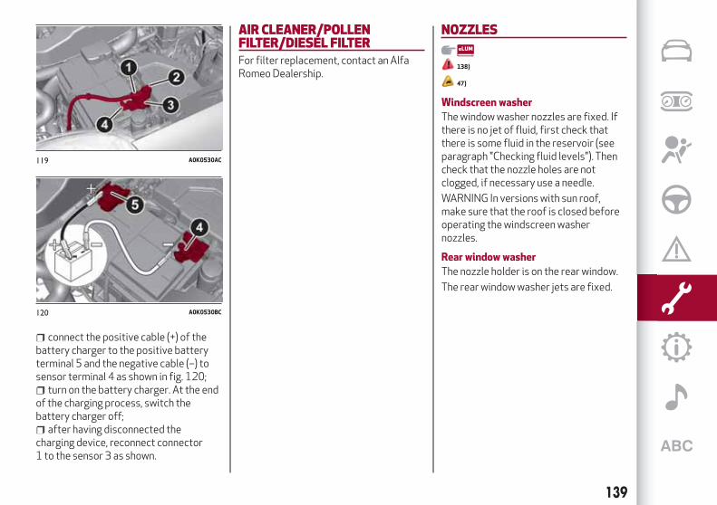
connect the positive cable (+) of thebattery charger to the positive batteryterminal 5 and the negative cable (–) tosensor terminal 4 as shown in fig. 120;
turn on the battery charger. At the endof the charging process, switch thebattery charger off;
after having disconnected thecharging device, reconnect connector1 to the sensor 3 as shown.
AIR CLEANER/POLLENFILTER/DIESEL FILTERFor filter replacement, contact an AlfaRomeo Dealership.
NOZZLES
138)
47)
Windscreen washer
The window washer nozzles are fixed. Ifthere is no jet of fluid, first check thatthere is some fluid in the reservoir (seeparagraph "Checking fluid levels"). Thencheck that the nozzle holes are notclogged, if necessary use a needle.
WARNING In versions with sun roof,make sure that the roof is closed beforeoperating the windscreen washernozzles.
Rear window washer
The nozzle holder is on the rear window.
The rear window washer jets are fixed.
119 A0K0530AC
120 A0K0530BC
139

HEADLIGHTWASHERS
(for versions/markets, where provided)
These are located within the frontbumper.
They are activated when the dippedbeam and/or main beam headlights areon and the windscreen washer isactivated.
Check the correct condition andcleanliness of nozzles at regularintervals.
WARNING
138)Driving with worn windscreen/rearwindowwiper blades is a serious hazard,because visibility is reduced in badweather.
IMPORTANT
47)Do not operate thewindscreenwiperwith the blades lifted from thewindscreen.
BATTERYThe battery 5 (see previous pages) doesnot require the electrolyte to be toppedup with distilled water. A periodic checkcarried out at an Alfa Romeo Dealershipis, however, necessary to checkefficiency.
INSPECTINGTHE CHARGEANDTHEELECTROLYTE LEVEL
139) 140) 141) 142)
48)
5)
If necessary, replace the battery withanother original battery with the samespecifications. Follow the batterymanufacturer's instructions formaintenance.
USEFULADVICE FOR EXTENDINGTHELIFE OFYOURBATTERYTo avoid draining your battery and makeit last longer, observe the followinginstructions:
when you park the car, ensure that thedoors, tailgate and bonnet are closedproperly, to prevent any lights fromremaining on inside the passenger'scompartment;
switch off all roof lights inside the car:the car is however equipped with asystem which switches all internal lightsoff automatically;
140
SE
RV
ICIN
GA
ND
MA
INT
EN
AN
CE

do not keep accessories (e.g. radio,hazard warning lights, etc.) switched onfor a long time when the engine is notrunning;
before performing any operation onthe electrical system, disconnect thenegative battery cable.
IMPORTANT Every time the battery isdisconnected, the steering must beinitialised. This is indicated by theappearance of the icon . To carry outthis procedure, simply turn the steeringwheel all the way from one end to theother or drive in a straight line for about ahundred metres.
IMPORTANT If the charge level remainsunder 50% for a long time, the battery isdamaged by sulphation, reducing itscapacity and efficiency at start-up.
The battery will also be more at risk offreezing (this can happen as early as-10°C). Refer to the "Vehicle inactivity"paragraph in "Starting and driving"chapter if the vehicle is left parked for along time.
If, after purchasing the car, you wish toinstall electrical accessories whichrequire permanent electrical supply (e.g.alarm, etc.) or accessories whichinfluence the electrical supplyrequirements, contact an Alfa Romeo
Dealership, whose qualified staff willevaluate the overall electricalconsumption.
WARNING
139)Battery fluid is poisonous andcorrosive. Avoid contact with the skin andeyes. Keep open flames away from thebattery and do not use objects thatmightcreate sparks: risk of explosion and fire.140)Using the battery with insufficientfluid irreparably damages the battery andmay cause an explosion.141) If the vehiclemust remain unused for along time at a very low temperature, removethe battery and take it to awarmplace, toavoid freezing.142)When performing any operation on thebattery or near it, always protect your eyeswith special goggles.
IMPORTANT
48) Incorrect installation of electric andelectronic devicesmay cause severe damageto your car. After purchasing your vehicle, ifyouwish to install any accessories (e.g.anti-theft, radio phone, etc.), go to anAlfaRomeoDealership, whichwill suggest themost suitable devices and advise youwhether a higher capacity battery needs tobe installed.
IMPORTANT
5)Batteries contain substanceswhich arevery dangerous for the environment. Forbattery replacement, contact an Alfa RomeoDealership.
141

LIFTINGTHEVEHICLEIf the car needs to be jacked up, go to anAlfa Romeo Dealership which is equippedwith shop jacks and jack arms.
IMPORTANT Be careful when positioningthe arm of the lift for versions with sideskirts.
BODYWORK
PRESERVINGTHEBODYWORK
Paint 6) 49)
Touch up abrasions and scratchesimmediately to prevent the formation ofrust.
Maintenance of paintwork consists ofwashing the car: the frequency dependson the conditions and environment wherethe car is used. For example, it isadvisable to wash the car more often inareas with high environmental pollutionor salted roads.
On some versions the car may beequipped, on request, with an exclusiveopaque paint on the roof which, in orderto be maintained intact, requires specialcare: see the instructions in the warning.
50)
To correctly wash the vehicle, followthese instructions:
if the vehicle is washed remove theaerial from the roof;
if high pressure jets or cleaners areused to wash the car, keep a distance ofat least 40 cm from the bodywork toavoid damage or alteration. Bear in mindthat a build up of water could causedamage to the car in the long term;
wash the bodywork using a lowpressure jet of water;
wipe a sponge with a slightly soapysolution over the bodywork, frequentlyrinsing the sponge;
rinse well with water and dry with a jetof air or a chamois leather.
Dry the less visible parts (e.g. doorframes, bonnet, headlight frames, etc.)with special care, as water may stagnatemore easily in these areas. Do not washthe car after it has been left in the sun orwith the bonnet hot: this may alter theshine of the paintwork.
Exterior plastic parts must be cleaned inthe same way as the rest of the vehicle.
IMPORTANTNOTES
Avoid parking under trees; the resindropped by trees makes the paintworkgo opaque and increases the possibilityof corrosion.
Bird droppings must be washed offimmediately and thoroughly as the acidthey contain is particularly aggressive.
Windows
Use specific detergents and clean clothsto prevent scratching or altering thetransparency.
IMPORTANT Wipe the rear window insidegently with a cloth following the directionof the filaments to avoid damaging theheating device.
142
SE
RV
ICIN
GA
ND
MA
INT
EN
AN
CE

Front headlights
Use a soft cloth soaked in water anddetergent for washing cars.
IMPORTANT Never use aromaticsubstances (e.g. petrol) or ketones (e.g.acetone) for cleaning the plastic lensesof the headlights.
IMPORTANT When cleaning with apressure washer, keep the water jet atleast 20 cm away from the headlights.
Engine compartment
At the end of every winter, wash theengine compartment thoroughly, takingcare not to aim the jet of water directly atthe electronic control units or at thewindscreen wiper motors. Have thisoperation performed at a specialisedworkshop.
IMPORTANT The washing should takeplace with the engine cold and theignition key in the STOP position. Afterthe washing operation, make sure thatthe various protections (e.g. rubber capsand guards) have not been removed ordamaged.
IMPORTANT
6)Detergents pollute the environment. Onlywash your vehicle in areas equipped tocollect and treatwastewater from this typeof activity.
IMPORTANT
49) In order to preserve the aestheticappearance of the paint abrasive productsand/or polishes should not be used forcleaning the vehicle.50)Avoid washingwith rollers and/orbrushes in washing stations.Wash thevehicle only by hand using neutral pHdetergents; dry it with awet chamois leather.Abrasive products and/or polishes shouldnot be used for cleaning the car. Birddroppingsmust bewashed off immediatelyand thoroughly as the acid they contain isparticularly aggressive. Avoid (if at allpossible) parking the vehicle under trees;remove vegetable resins immediately as,when dried, it may only be possible to removethemwith abrasive products and/or polishes,which is highly inadvisable as they could alterthe typical opaqueness of the paint. Do notuse purewindscreenwasher fluid forcleaning the front windscreen and rearwindow; dilute itmin. 50%withwater. Onlyuse pure screenwasher fluid when strictlynecessary due to outside temperatureconditions.
INTERIOR143) 144) 145)
Periodically check the cleanliness of theinterior, beneath the mats, which couldcause oxidation of the sheet metal.
SEATSAND FABRIC PARTSRemove dust with a soft brush or avacuum cleaner. It is advisable to use amoist brush on velvet upholstery. Rub theseats with a sponge moistened with asolution of water and neutral detergent.
LEATHERSEATS
(for versions/markets, where provided)
Remove the dry dirt with a chamois orslightly damp cloth, without exerting toomuch pressure. Remove any liquid orgrease stains using an absorbent drycloth, without rubbing. Then clean with asoft cloth or buckskin cloth dampenedwith water and mild soap. If the stainpersists, use specific products andobserve the instructions carefully.
IMPORTANT Never use alcohol. Makesure that the cleaning products usedcontain no alcohol or alcohol derivatives,even in small quantities.
PLASTIC AND COATEDPARTSClean interior plastic parts with a dampcloth (if possible made from microfibre),and a solution of water and neutral,non-abrasive detergent. To clean oily or
143

persistent stains, use specific productsfree from solvents and designed tomaintain the original appearance andcolour of the components.
Remove any dust using a microfibrecloth, if necessary moistened with water.The use of paper tissues is notrecommended as these may leaveresidues. 51)
GENUINE LEATHERPARTS
(for versions/markets, where provided)
Use only water and mild soap to cleanthese parts. Never use alcohol oralcohol-based products. Before using aspecific product for cleaning interiors,make sure that it does not containalcohol and/or alcohol based substances.
WARNING
143)Never use flammable products, such aspetrol ether or rectified petrol to clean theinside of the car. The electrostatic chargeswhich are generated by rubbing during thecleaning operationmay cause a fire.144)Do not keep aerosol cans in the car:theymight explode. Aerosol cansmust notbe exposed to a temperature exceeding50°C.When the vehicle is exposed tosunlight, the internal temperature cangreatly exceed this value.
145) Theremust be no obstacles on thefloor underneath the pedals; make sure thatmats are always flat and do not interferewith the pedals.
IMPORTANT
51)Never use alcohol, petrols andderivatives to clean the dashboard andinstrument panel lens.
144
SE
RV
ICIN
GA
ND
MA
INT
EN
AN
CE

Everything you may find useful for understanding how your car ismade and works is contained in this chapter and illustrated with
data, tables and graphics. For the enthusiasts and the technician,but also just for those who want to know every detail of their car.
TECHNICAL SPECIFICATIONSIDENTIFICATION DATA . . . . . . . . . . . . . . . . . . . . . . . . . .146VEHICLE IDENTIFICATION NUMBER (VIN) PLATE . . . . . . . . . .146VEHICLE IDENTIFICATION NUMBER . . . . . . . . . . . . . . . . .147ENGINE MARKING . . . . . . . . . . . . . . . . . . . . . . . . . . . . .147ENGINE . . . . . . . . . . . . . . . . . . . . . . . . . . . . . . . . . . .148WHEELS . . . . . . . . . . . . . . . . . . . . . . . . . . . . . . . . . . .154DIMENSIONS . . . . . . . . . . . . . . . . . . . . . . . . . . . . . . . .156WEIGHTS . . . . . . . . . . . . . . . . . . . . . . . . . . . . . . . . . .157REFUELLING . . . . . . . . . . . . . . . . . . . . . . . . . . . . . . . .160FLUIDS AND LUBRICANTS. . . . . . . . . . . . . . . . . . . . . . . .164PERFORMANCE . . . . . . . . . . . . . . . . . . . . . . . . . . . . . .167FUEL CONSUMPTION. . . . . . . . . . . . . . . . . . . . . . . . . . .168CO2 EMISSIONS . . . . . . . . . . . . . . . . . . . . . . . . . . . . . .170PRESCRIPTIONS FOR HANDLING THE VEHICLE AT THE END OF ITSLIFE . . . . . . . . . . . . . . . . . . . . . . . . . . . . . . . . . . . . . .171

IDENTIFICATIONDATAThe identification data of the vehicle are:
VIN plate;Chassis marking;Bodywork paint identification plate;Engine marking.
VEHICLE IDENTIFICATIONNUMBER (VIN) PLATEThis plate is fitted to the enginecompartment front crossmember andcontains the following identification datafig. 121:
A: Name of Manufacturer
B: Type-approval number
C: Vehicle type identification code
D: Chassis number
E: Maximum permitted weight of vehiclefully laden
F: Maximum permitted weight of vehiclefully laden plus trailer
G: Maximum permitted weight on frontaxle
H: Maximum permitted weight on second(rear) axle
I: Engine type
L: Bodywork version code
M Spares number
N: Smoke opacity index (for dieselengines)
121 A0K0024C
146
TE
CH
NIC
AL
SP
EC
IFIC
ATIO
NS

VEHICLE IDENTIFICATIONNUMBERThis is printed on the passengercompartment floor, next to the frontright seat.
Slide forward hatch 1 fig. 122 to access.
The marking includes:vehicle type (ZAR 940000);chassis serial number.
ENGINEMARKINGIt is stamped on the cylinder block andincludes the type and the engine serialnumber.
122 A0K0750C
147

ENGINE
GENERAL INFORMATION 1.4 Turbo petrol 120 HP 1.4 Turbo Petrol/LPG 120 HP
Engine code 940B7000 940B7000
Cycle Otto Otto
Number and position of cylinders 4 in line 4 in line
Piston bore and stroke (mm) 72.0 × 84.0 72.0 × 84.0
Total displacement (cm³) 1368 1368
Compression ratio 9.8 9.8
LPG PETROL
Maximum power (EC) (kW) 88 88 88
Maximum power (EEC) (HP) 120 120 120
corresponding engine speed (rpm) 5000 5000 5000
Maximum torque (EC) (Nm) 215 215 215
Maximum torque (EC) (kgm) 22 22 22
corresponding engine speed (rpm) 2500 2500 2500
Spark plugs NGK IKR9J8 NGK IKR9J8 NGK IKR9J8
FuelUnleaded petrol 95 R.O.N. (EN
228 specifications)
LPG for motorvehicles
(EN589 Specification)
Unleaded petrol95 R.O.N. (EN
228 specifications)
148
TE
CH
NIC
AL
SP
EC
IFIC
ATIO
NS

GENERAL INFORMATION 1.4 Turbo MultiAir 150 HP 1.4 Turbo MultiAir 163 HP (*)
Engine code 940C2000 955A8000
Cycle Otto Otto
Number and position of cylinders 4 in line 4 in line
Piston bore and stroke (mm) 72.0 × 84.0 72.0 × 84.0
Total displacement (cm³) 1368 1368
Compression ratio 10 10
Maximum power (EC) (kW) 110 120
Maximum power (EEC) (HP) 150 163
corresponding engine speed (rpm) 5500 5500
NATURAL DYNAMIC NATURAL DYNAMIC
Maximum torque (EC) (Nm) 230 250 230 250
Maximum torque (EC) (kgm) 23.4 25.4 23.4 25.4
corresponding engine speed (rpm) 2250 2500 2250 2500
Spark plugs NGK IKR9F8 NGK IKR9J8
FuelUnleaded petrol 95 R.O.N.
(EN228 specifications)Unleaded petrol 95 R.O.N.
(EN228 specifications)
(*) For versions/markets, where provided
149

GENERAL INFORMATION 1.4 Turbo MultiAir 170 HP 1750Turbo Petrol 240 HP (*)
Engine code 940A2000 940B2000
Cycle Otto Otto
Number and position of cylinders 4 in line 4 in line
Piston bore and stroke (mm) 72.0 × 84.0 83.0 × 80.5
Total displacement (cm³) 1368 1742
Compression ratio 10 9.25 ± 0.25
Maximum power (EC) (kW) 125 177
Maximum power (EEC) (HP) 170 240
corresponding engine speed (rpm) 5500 5750
NATURAL DYNAMIC NATURAL DYNAMIC
Maximum torque (EC) (Nm) 230 250 300 340
Maximum torque (EC) (kgm) 23.4 25.4 30.5 34.6
corresponding engine speed (rpm) 2250 2500 1850 2000
Spark plugs NGK IKR9J8 NGK ILKAR7D6G
Fuel95 RON or 98 RON (EN228 specification)
unleaded petrol95 RON or 98 RON
(EN228 specification) unleaded petrol
(*) For versions/markets, where provided
150
TE
CH
NIC
AL
SP
EC
IFIC
ATIO
NS
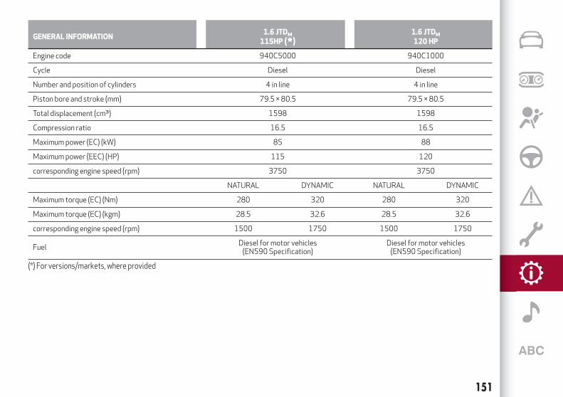
GENERAL INFORMATION1.6 JTDM115HP (*)
1.6 JTDM120 HP
Engine code 940C5000 940C1000
Cycle Diesel Diesel
Number and position of cylinders 4 in line 4 in line
Piston bore and stroke (mm) 79.5 × 80.5 79.5 × 80.5
Total displacement (cm³) 1598 1598
Compression ratio 16.5 16.5
Maximum power (EC) (kW) 85 88
Maximum power (EEC) (HP) 115 120
corresponding engine speed (rpm) 3750 3750
NATURAL DYNAMIC NATURAL DYNAMIC
Maximum torque (EC) (Nm) 280 320 280 320
Maximum torque (EC) (kgm) 28.5 32.6 28.5 32.6
corresponding engine speed (rpm) 1500 1750 1500 1750
FuelDiesel for motor vehicles
(EN590 Specification)Diesel for motor vehicles
(EN590 Specification)
(*) For versions/markets, where provided
151

GENERAL INFORMATION2.0 JTD
M
136HP2.0 JTDM150 HP
Engine code 940C4000 940C3000
Cycle Diesel Diesel
Number and position of cylinders 4 in line 4 in line
Piston bore and stroke (mm) 83 × 90.4 83 × 90.4
Total displacement (cm³) 1956 1956
Compression ratio 16.5 16.5
NATURAL DYNAMIC
Maximum power (EC) (kW) 100 103 110
Maximum power (EEC) (HP) 136 140 150
corresponding engine speed (rpm) 4500 4000 4500
NATURAL DYNAMIC NATURAL DYNAMIC
Maximum torque (EC) (Nm) 320 380 320 380
Maximum torque (EC) (kgm) 32.5 38.7 32.5 38.7
corresponding engine speed (rpm) 1500 1750 1500 1750
FuelDiesel for motor vehicles
(EN590 Specification)Diesel for motor vehicles
(EN590 Specification)
152
TE
CH
NIC
AL
SP
EC
IFIC
ATIO
NS

GENERAL INFORMATION2.0 JTD
M
163HP (*)2.0 JTDM175HP
Engine code 940B9000 940B4000
Cycle Diesel Diesel
Number and position of cylinders 4 in line 4 in line
Piston bore and stroke (mm) 83 × 90.4 83 × 90.4
Total displacement (cm³) 1956 1956
Compression ratio 16.5 16.5
NATURAL DYNAMIC
Maximum power (EC) (kW) 120 125 128.5
Maximum power (EEC) (HP) 163 170 175
corresponding engine speed (rpm) 4000 3750 3750
NATURAL DYNAMIC NATURAL DYNAMIC
Maximum torque (EC) (Nm) 320 350 320 350
Maximum torque (EC) (kgm) 32.5 35.6 32.5 35.6
corresponding engine speed (rpm) 1500 1750 1500 1750
FuelDiesel for motor vehicles
(EN590 Specification)Diesel for motor vehicles
(EN590 Specification)
(*) For versions/markets, where provided
153
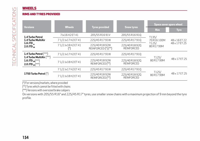
WHEELS
RIMSANDTYRES PROVIDED
Versions Wheels Tyres provided Snow tyresSpace saver spare wheel
Rim Tyre
1.4 Turbo Petrol1.4 Turbo MultiAir1.6 JTD
M
2.0 JTD M
7Jx16 H2 ET 41 205/55 R16 91V 205/55 R16 91QT135/70 R16 100MT125/80 R17 99M
4B x 16 ET 224B x 17 ET 25
7 1/2 Jx17 H2 ET 41 225/45 R17 91W 225/45 R17 91Q
7 1/2 Jx18 H2 ET 41(*)
225/40 R18 92WREINFORCED (*) (**)
225/40 R18 92QREINFORCED
1.4 Turbo Petrol (***)1.4 Turbo MultiAir (***)1.6 JTD M
2.0 JTD M
7 1/2 Jx17 H2 ET 41 225/45 R17 91W 225/45 R17 91QT125/
80 R17 99M4B x 17 ET 25
7 1/2 Jx18 H2 ET 41225/40 R18 92WREINFORCED (**)
225/40 R18 92QREINFORCED
1750Turbo Petrol (*)
7 1/2 Jx17 H2 ET 41 225/45 R17 91W 225/45 R17 91QT125/
80 R17 99M4B x 17 ET 25
7 1/2 Jx18 H2 ET 41225/40 R18 92WREINFORCED (**)
225/40 R18 92QREINFORCED
(*) For versions/markets, where provided(**) Tyres which cannot be fitted with chains(***) Versions with oversized brake calipersOn versions with 205/55 R16” and 225/45 R17” tyres, use smaller snow chains with a maximum projection of 9 mm beyond the tyreprofile.
154
TE
CH
NIC
AL
SP
EC
IFIC
ATIO
NS
(***)(***)

COLDTYRE INFLATIONPRESSURE
TYRES PROVIDED
VERSIONS MEASUREMENTMEDIUM LOAD FULL LOAD
Front Rear Front Rear
1.4 Turbo Petrol1.6 JTD M
205/55 R16 91V225/45 R17 91W
225/40 R18 92W REINFORCED
2.32.32.6
2.12.12.2
2.72.73.0
2.32.32.6
1.4 Turbo MultiAir2.0 JTD
M
205/55 R16 91V225/45 R17 91W
225/40 R18 92W REINFORCED
2.32.3/2.8 (*)
2.6
2.12.1/2.6 (*)
2.2
2.72.7/2.8 (*)
3.0
2.32.3/2.6 (*)
2.6
1750Turbo Petrol(*)225/45 R17 91W
225/40 R18 92W REINFORCED2.32.6
2.12.2
2.73.0
2.32.6
Space saver sparewheel
T135/70 R16 100MT125/80 R17 99M
4.2
(*) For versions/markets, where providedWhen the tires are warm, the inflation pressure should be + 0.3 bar in relation to the recommended figure. Check correct pressurewhen the tyres are cold.
With snow tyres, add +0.2 bar to the prescribed pressure for standard tyres.
When travelling at speeds over 160 km/h, inflate the tyres to the values specified for fully laden conditions.
155

DIMENSIONSDimensions are expressed in mm and refer to the vehicle equipped with its standard-supplied tyres. Height is measured with vehicleunladen.
LUGGAGE COMPARTMENTVOLUMEUnladen capacity (V.D.A. standards) = 350 dm 3
A B C D E F G H
4351 955 2634 762 1465 1554 1798 1554
Small variations in size are possible depending on the dimensions of the rims.
123 A0K0822C
156
TE
CH
NIC
AL
SP
EC
IFIC
ATIO
NS

WEIGHTS
Weights 1.4 Turbo Petrol 1.4 Turbo MultiAir (*) 1.4 Turbo MultiAir (**)
Unladen weight (with all fluids, fuel tank filled to90% and without optional equipment)
1280 1290 1305
Payload including the driver (***) 505 505 505
Maximum permitted loads (****)
– front axle 1100 1100 1100
– rear axle 850 850 850
– total 1785 1795 1810
Towable loads (kg)
– braked trailer 1300 1300 1300 / 0 (****)
– trailer without brakes 500 500 500
Maximum load on roof 50 50 50
Maximum load on tow hitch (trailer with brakes) 60 60 60
(*) Versions with manual gearbox(**) Versions with Alfa TCT(***) If special equipment is fitted (sunroof, tow hitch, etc.) the unladen car weight increases, thus reducing the specified payload in relation to the
maximum permissible loads.(****) Hot-humid climate countries
157

Weights1.4 Turbo Petrol/LPG
120 HP1750Turbo Petrol240 HPTCT(*)
1.6 JTDM(**)
Unladen weight (with all fluids, fuel tank filled to 90% andwithout optional equipment)
1317 1320 1310
Payload including the driver (***) 503 535 540
Maximum permitted loads (****)
– front axle 1100 1100 1100
– rear axle 890 850 850
– total 1820 1855 1850
Towable loads (kg)
– braked trailer 1300 1000 1300
– trailer without brakes 500 500 500
Maximum load on roof 50 50 50
Maximum load on tow hitch (trailer with brakes) 60 60 60
(*) For versions/markets, where provided(**) Versions with manual gearbox(***) If special equipment is fitted (sunroof, tow hitch, etc.) the unladen car weight increases, thus reducing the specified payload in relation to the
maximum permissible loads.(****) Loads not to be exceeded. The user is responsible for arranging goods in the luggage compartment and/or load platform within the maximum
permitted loads.
158
TE
CH
NIC
AL
SP
EC
IFIC
ATIO
NS

Weights 1.6 JTDM(**) 2.0 JTDM(*) 2.0 JTDM(**)
Unladen weight (with all fluids, fuel tank filled to 90% andwithout optional equipment)
1320 1320 1335
Payload including the driver (***) 540 540 540
Maximum permitted loads (****)
– front axle 1100 1100 1100
– rear axle 850 850 850
– total 1860 1860 1875
Towable loads (kg)
– braked trailer 600 1300 600
– trailer without brakes 500 500 500
Maximum load on roof 50 50 50
Maximum load on tow hitch (trailer with brakes) 60 60 60
(**) Versions with Alfa TCT(*) Versions with manual gearbox(***) If special equipment is fitted (sunroof, tow hitch, etc.) the unladen car weight increases, thus reducing the specified payload in relation to the
maximum permissible loads.(****) Loads not to be exceeded. The user is responsible for arranging goods in the luggage compartment and/or load platform within the maximum
permitted loads.
159
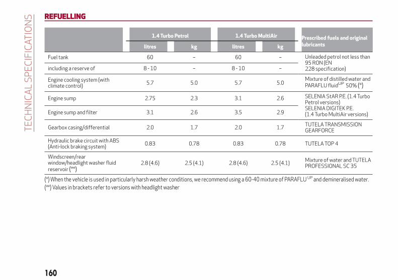
REFUELLING
1.4 Turbo Petrol 1.4 Turbo MultiAir Prescribed fuels and originallubricantslitres kg litres kg
Fuel tank 60 – 60 – Unleaded petrol not less than95 RON (EN228 specification)including a reserve of 8 - 10 – 8 - 10 –
Engine cooling system (withclimate control)
5.7 5.0 5.7 5.0Mixture of distilled water andPARAFLU fluidUP 50% (*)
Engine sump 2.75 2.3 3.1 2.6 SELENIA StAR P.E. (1.4 TurboPetrol versions)SELENIA DIGITEK P.E.(1.4 Turbo MultiAir versions)Engine sump and filter 3.1 2.6 3.5 2.9
Gearbox casing/differential 2.0 1.7 2.0 1.7TUTELA TRANSMISSIONGEARFORCE
Hydraulic brake circuit with ABS(Anti-lock braking system)
0.83 0.78 0.83 0.78 TUTELA TOP 4
Windscreen/rearwindow/headlight washer fluidreservoir (**)
2.8 (4.6) 2.5 (4.1) 2.8 (4.6) 2.5 (4.1)Mixture of water and TUTELAPROFESSIONAL SC 35
(*) When the vehicle is used in particularly harsh weather conditions, we recommend using a 60-40 mixture of PARAFLU UP and demineralised water.(**) Values in brackets refer to versions with headlight washer
160
TE
CH
NIC
AL
SP
EC
IFIC
ATIO
NS

1.4 Turbo Petrol/LPG 120 HPPrescribed fuels and original lubricants
litres kg
Fuel tank (Petrol/LPG) 60/38 – Unleaded petrol not less than 95 RON (EN228 specification)/LPGIncluding a reserve of (petrol/LPG) 8 - 10/8 –
Engine cooling system (with climate control) 5.7 5.0Mixture of demineralised water and 50%PARAFLU UP(*)
Engine sump 2.75 2.3SELENIA MULTIPOWER GAS 5W-40
Engine sump and filter 3.1 2.6
Gearbox casing/differential 2.0 1.7 TUTELA TRANSMISSION GEARFORCE
Hydraulic brake circuit with ABS (Anti-lockbraking system)
0.83 0.78TUTELA TOP 4
Windscreen/rear window/headlight washerfluid reservoir(**)
2.8 (4.6) 2.5 (4.1) Mixture of water and TUTELAPROFESSIONAL SC 35
(*) When the vehicle is used in particularly harsh weather conditions, we recommend using a 60-40 mixture of PARAFLU UP and demineralised water.(**) Values in brackets refer to versions with headlight washer
161

1750Turbo Petrol 240 HP (*)Prescribed fuels and original lubricants
litres kg
Fuel tank 60 – Unleaded petrol not less than 95 RON (EN228 specification)including a reserve of 8 - 10 –
Engine cooling system (with climate control) 6.4 5.7Mixture of distilled water andPARAFLU UP fluid 50% (***)
Engine sump 5.0 4.25SELENIA SPORT POWER
Engine sump and filter 5.1 4.35
Automatic transmission casing 2.0 1.7 TUTELA TRANSMISSION GEARFORCE
Hydraulic brake circuit with ABS (Anti-lockbraking system)
0.83 0.78 TUTELA TOP 4
Windscreen/rear window/headlight washerfluid reservoir(**)
2.8 (4.6) 2.5 (4.1)Mixture of water and TUTELAPROFESSIONAL SC 35
(*) For versions/markets, where provided(***) When the vehicle is used in particularly harsh weather conditions, we recommend using a 60-40 mixture of PARAFLU UP and demineralised water.(**) Values in brackets refer to versions with headlight washer
162
TE
CH
NIC
AL
SP
EC
IFIC
ATIO
NS
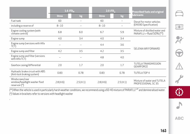
1.6 JTDM 2.0 JTDM Prescribed fuels and original
lubricantslitres kg litres kg
Fuel tank 60 – 60 – Diesel for motor vehicles(EN590 Specification)including a reserve of 8 - 10 – 8 - 10 –
Engine cooling system (withclimate control)
6.8 6.0 6.7 5.9Mixture of distilled water andPARAFLU UP fluid 50% (**)
Engine sump 4.0 3.4 4.0 3.4
SELENIA WR FORWARD
Engine sump (versions with AlfaTCT)
– – 4.4 3.6
Engine sump and filter 4.2 3.5 4.2 3.5
Engine sump and filter (versionswith Alfa TCT)
– – 4.8 4.0
Gearbox casing/differential 2.0 1.7 2.0 1.7TUTELA TRANSMISSIONGEARFORCE
Hydraulic brake circuit with ABS(Anti-lock braking system)
0.83 0.78 0.83 0.78 TUTELA TOP 4
Windscreen/rearwindow/headlight washer fluidreservoir (*)
2.8 (4.6) 2.5 (4.1) 2.8 (4.6) 2.5 (4.1)Mixture of water and TUTELAPROFESSIONAL SC 35
(**) When the vehicle is used in particularly harsh weather conditions, we recommend using a 60-40 mixture of PARAFLU UP and demineralised water.(*) Values in brackets refer to versions with headlight washer
,
163

FLUIDSAND LUBRICANTSYour vehicle is equipped with an engine oil that has been thoroughly developed and tested in order to meet the requirements of theScheduled Servicing Plan. Constant use of the prescribed lubricants guarantees the fuel consumption and emission specifications.Lubricant quality is crucial for engine operation and duration.
PRODUCTSPECIFICATIONS
52)
Use Features SpecificationOriginal fluids and
lubricantsReplacement interval
Lubricant for petrolengines (1.4 Turbo Petrolversions)
SAE 5W-40 ACEA C3 /API SN
9.55535-S2SELENIA StAR P.E.Contractual TechnicalReference No. F603.D08
According to ScheduledServicing Plan
Lubricant for petrolengines (1.4 TurboMultiAir versions)
SAE 0W30 ACEA C2 /API SN
9.55535-GS1 orMS.90048
SELENIA DIGITEK P.E.Contractual TechnicalReference N° F020.B12
According to ScheduledServicing Plan
Lubricant for petrolengines (for 1750 Turbopetrol versions only)
SAE 5W-40 ACEA C3 9.55535-GH2SELENIA SPORTPOWERContractual TechnicalReference No. F052.H12
According to ScheduledServicing Plan
Lubricant for dieselengines
SAE 0W-30 ACEA C2 /API SN
FIAT 9.55535-DS1 orMS.90047
SELENIAWR FORWARDContractual TechnicalReference No. F842.F13
According to ScheduledServicing Plan
Lubricants forpetrol/LPG engines
SAE 5W-40 ACEA C3. FIAT 9.55535-T2
SELENIA MULTIPOWERGAS 5W-40Contractual TechnicalReference No. F922.E09
According to ScheduledServicing Plan
If lubricants conforming to the required specification are not available, products that meet the indicated specifications can be usedto top up; in this case optimal performance of the engine is not guaranteed.
164
TE
CH
NIC
AL
SP
EC
IFIC
ATIO
NS
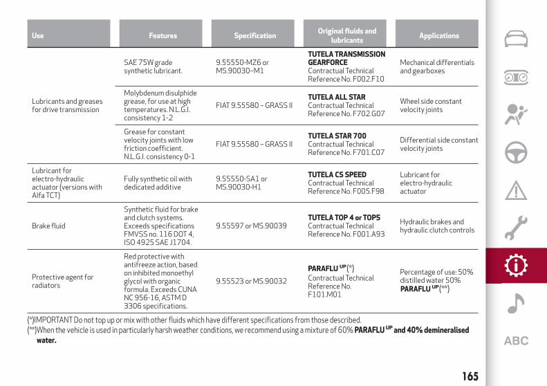
Use Features SpecificationOriginal fluids and
lubricantsApplications
Lubricants and greasesfor drive transmission
SAE 75W gradesynthetic lubricant.
9.55550-MZ6 orMS.90030–M1
TUTELATRANSMISSIONGEARFORCEContractual TechnicalReference No. F002.F10
Mechanical differentialsand gearboxes
Molybdenum disulphidegrease, for use at hightemperatures. N.L.G.I.consistency 1-2
FIAT 9.55580 – GRASS IITUTELA ALL STARContractual TechnicalReference No. F702.G07
Wheel side constantvelocity joints
Grease for constantvelocity joints with lowfriction coefficient.N.L.G.I. consistency 0-1
FIAT 9.55580 – GRASS IITUTELA STAR 700Contractual TechnicalReference No. F701.C07
Differential side constantvelocity joints
Lubricant forelectro-hydraulicactuator (versions withAlfa TCT)
Fully synthetic oil withdedicated additive
9.55550-SA1 orMS.90030-H1
TUTELA CS SPEEDContractual TechnicalReference No. F005.F98
Lubricant forelectro-hydraulicactuator
Brake fluid
Synthetic fluid for brakeand clutch systems.Exceeds specificationsFMVSS no. 116 DOT 4,ISO 4925 SAE J1704.
9.55597 or MS.90039TUTELATOP 4 or TOP5Contractual TechnicalReference No. F001.A93
Hydraulic brakes andhydraulic clutch controls
Protective agent forradiators
Red protective withantifreeze action, basedon inhibited monoethylglycol with organicformula. Exceeds CUNANC 956-16, ASTM D3306 specifications.
9.55523 or MS.90032
PARAFLU UP
Contractual TechnicalReference No.F101.M01
Percentage of use: 50%distilled water 50%
(*)IMPORTANT Do not top up or mix with other fluids which have different specifications from those described.(**)When the vehicle is used in particularly harsh weather conditions, we recommend using a mixture of 60% PARAFLU UP and 40%demineralised
water.
165
(*)
PARAFLU UP(**)

Use Features SpecificationOriginal fluids and
lubricantsApplications
Diesel fuel additiveAntifreeze additive fordiesel, with protectiveaction for diesel engines.
TUTELA DIESEL ARTContractual TechnicalReference No. F601.L06
To be mixed with diesel(25 cc per 10 litres)
Washer fluid forwindscreen/rearwindow/headlamps
Mixture of alcohol, waterand surfactants CUNANC 956-11
9.55522 or MS.90043
TUTELA PROFESSIONALSC 35Contractual TechnicalReference No. F201.D02
To be used diluted orundiluted in windscreenwasher/wiper systems
IMPORTANT
52) The use of productswith different specifications than those indicated above could cause damage to the engine that is not covered by thewarranty.
166
TE
CH
NIC
AL
SP
EC
IFIC
ATIO
NS

PERFORMANCE
Versions Maximum speed (km/h)Acceleration from 0-100 km/h
(sec)
1.4 Turbo petrol 120 HP 195 9.4
1.4 Turbo Multi Air 163 HPTCT(*) 218 7.8
1.4 Turbo Multi Air 150 HP 210 8.2
1.4 Turbo Multi Air 170 HPTCT 218 7.7
1.4 Turbo Petrol/LPG 120 HP 195 9.4
1750Turbo Petrol 240 HP (*) 244 6.0
1.6 JTD M 115 HP 192 10.5
1.6 JTD M 120 HP 195 10
2.0 JTD M 136 HP 205 9.2
2.0 JTDM 150 HP 210 8.8
2.0 JTD M 163 HPTCT 215 8.2
2.0 JTD M 175 HPTCT 219 7.8
(*) For versions/markets, where provided(**) For versions with manual transmission or TCT
167
(*)(**)
(**)
(*)

FUEL CONSUMPTIONThe fuel consumption figures given in the tables below are determined on the basis of the type-approval tests laid down by specificEuropean Directives.
The following procedures are used to measure the fuel consumption:urban cycle: cold starting followed by driving that simulates urban use of the car;extra-urban cycle: frequent accelerating in all gears, simulating extra-urban use of the car: speed varies between 0 and 120 km/h;combined fuel consumption: calculated with a weighting of approximately 37% of the urban cycle and 63% of the extra-urban
cycle.
IMPORTANT The type of route, traffic conditions, weather conditions, driving style, general condition of the car, trimlevel/equipment/accessories, use of the climate control system, car load, presence of roof racks and other situations that adverselyaffect the aerodynamics or wind resistance lead to different fuel consumption values than those measured.
FUEL CONSUMPTIONACCORDINGTOTHE CURRENTEUROPEANDIRECTIVE (litres/100 km)
Versions Urban Extra-urban Combined
1.4 Turbo Petrol 8.1 5.1 6.2
1.4 Turbo Petrol/LPG 120 HP 10.8(*) / 8.4(**) 6.7(*) / 5.1(**) 8.2(*) / 6.3(**)
1.4 Turbo MultiAir 150 HP 7.4 4.4 5.5
1.4 Turbo MultiAir 163 HPTCT(***) /170 HPTCT 6.3 4.1 4.9
1750Turbo Petrol 240 HP(***) 9.5 5.2 6.8
1.6 JTD M115 HP 4.9/4.7(*****) 3.3/3.2(*****) 3.9/3.8(*****)
1.6 JTD M 120 HP 4.9/4.7(*****) 3.3/3.2(*****) 3.9/3.8(*****)
2.0 JTD M136 HP 5.0 3.7 4.2
(*) Running on LPG(**) Running on petrol(***) For versions/markets, where provided(****) For versions with manual transmission or TCT(*****) ECO version
168
TE
CH
NIC
AL
SP
EC
IFIC
ATIO
NS
(***)(****)
(****)

Versions Urban Extra-urban Combined
2.0 JTDM150 HP 5.0/4.8(*****) 3.7/3.5(*****) 4.2/4.0(*****)
2.0 JTD M 163 HPTCT 5.1 3.8 4.3
2.0 JTD M 175 HPTCT 5.1 3.8 4.3
(*****) ECO version(***) For versions/markets, where provided
169
(***)

CO2 EMISSIONSThe CO
2emission levels given in the following tables refer to combined consumption.
Versions CO2 emissions according to the European Directive in force (g/km)
1.4 Turbo Petrol 144
1.4 Turbo Petrol/LPG 120 HP 133(*) / 147(**)
1.4 Turbo MultiAir 150 HP 127
1.4 Turbo MultiAir 163 HPTCT(***) 114
1.4 Turbo MultiAir 170 HPTCT 114
1750Turbo Petrol 240 HP(***) 157
1.6 JTD M115 HP 103/99(*****)
1.6 JTD M 120 HP 103/99(*****)
2.0 JTD M136 HP 110
2.0 JTDM150 HP 110/105(*****)
2.0 JTD M163 HPTCT 113
2.0 JTD M 175 HPTCT 113
(*) Running on LPG(**) Running on petrol(***) For versions/markets, where provided(****) For versions with manual transmission or TCT(*****) ECO version
170
TE
CH
NIC
AL
SP
EC
IFIC
ATIO
NS
(****)
(****)
(***)

PRESCRIPTIONS FORHANDLINGTHEVEHICLE ATTHE ENDOF ITS LIFE
(where present)
FCA has been committed for many years to safeguarding the environment through the constant improvement of its productionprocesses and manufacturing products that are increasingly "eco-compatible". To grant customers the best possible service in termsof respecting environmental laws and in response to European Directive 2000/53/EC governing vehicles at the end of their life, FCAis offering its customers the chance to hand over their vehicle at the end of its life without incurring any additional costs. TheEuropean Directive sets out that when the vehicle is handed over, the last keeper or owner should not incur any expenses as a resultof it having a zero or negative market value.
To hand your vehicle over at the end of its life without extra cost, contact one of our dealerships if you are purchasing another vehicleor an FCA-authorised collection and scrapping centre. These centres have been carefully chosen to offer high quality service for thecollection, treatment and recycling of vehicles at their end of life, respecting the surrounding environment.
You can find further information on these collection and scrapping centres either from an FCA dealership or by calling the number inthe Warranty Booklet or by consulting the websites of the various FCA brands.
171

172
This page is intentionally left blank

This chapter describes the main functions of the infotainmentsystems for the Uconnect™ 5" Radio LIVE, or Uconnect™ 6.5"
Radio Nav LIVE that can be fitted on the vehicle.
MULTIMEDIATIPS, CONTROLS AND GENERAL INFORMATION . . . . . . . . . .174Uconnect™ 5” Radio LIVE . . . . . . . . . . . . . . . . . . . . . . . . .175Uconnect™ 6.5” Radio Nav LIVE . . . . . . . . . . . . . . . . . . . . .187

TIPS, CONTROLSANDGENERALINFORMATION
TIPS
Road safety
Learn how to use the various systemfunctions before setting off.
Read the instructions for the systemcarefully before setting off. 146) 147)
Reception conditions
Reception conditions change constantlywhile driving. Reception may beinterfered with by the presence ofmountains, buildings or bridges,especially when you are far away fromthe broadcaster.
IMPORTANT The volume may beincreased when receiving trafficbulletins.
Care andmaintenance
53) 54)
Observe the following precautions toensure the system is fully operational:
never use alcohol, petrol orpetroleum-based solvents to clean thedisplay screen;
the display is sensitive to scratching,liquids and detergents. The displayshould not come into contact withpointed or rigid objects which coulddamage its surface. Do not press on thedisplay when cleaning it;
prevent any liquid from entering thesystem: this could damage it beyondrepair.
SAFETYSETTINGS
Look at the screen only and when it isnecessary and safe. If you need to look atthe screen for a long time, pull over to asafe place so as not to be distractedwhile driving.
Immediately stop using the system in theevent of a fault. Otherwise the systemmight be damaged. Contact an AlfaRomeo Dealership as soon as possible tohave the system repaired.
WARNING
146) Follow the safety rules here below:otherwise serious injuriesmay occur to theoccupants or the systemmay be damaged.147) If the volume is too loud this can bedangerous. Adjust the volume so that youcan still hear background noises (e.g. horns,ambulances, police vehicles, etc.).
IMPORTANT
53)Only clean the front panel and thedisplay lenswith a soft, clean, dry, anti-staticcloth. Cleaning and polishing productsmaydamage the surface. Never use alcohol,petrols and derivatives.
54)Do not use the display as a base forsupportswith suction pads or adhesives forexternal navigators or smartphones orsimilar devices
174
MU
LTIM
ED
IA

Uconnect™ 5” Radio LIVE
CONTROLSON FRONTPANEL
124 A0K0917C
175

FRONTPANEL CONTROL SUMMARYTABLE
Button Functions Mode
1 –
Switching on Short button press
Switching off Short button press
Volume adjustment Left/right rotation of knob
2 – Volume activation/deactivation (Mute/Pause) Short button press
3 – CD ejection Short button press
4 CD housing –
5 – Display on/off Short button press
6 – Exit the selection/return to previous screen Short button press
7 –BROWSE ENTERScrolling the list or tuning to a radio station Left/right rotation of knob
Confirmation of the option displayed Short button press
8 - APPSAccess to the additional functions: (for example, display
of Time, Compass, Outside temperature, Media RadioandUconnect™ LIVE services)
Short button press
9 – PHONE Access to the Phone mode Short button press
10 – SETTINGS Access to the main settings menu Short button press
11 –MEDIA Source selection: CD, USB/iPod, AUX,Bluetooth® Short button press
12 –RADIO Access to the Radio mode Short button press
176
MU
LTIM
ED
IA

STEERINGWHEEL CONTROLS
Description
The controls for the main system functions are present on the steering wheel fig. 125 to make control easier.
The activation of the function selected is controlled, in some cases, by how long the button is pressed (short or long press) asdescribed in the table below.
125 A0K0365C
177

STEERINGWHEEL CONTROL SUMMARYTABLE
Button Interaction
Acceptance of incoming call
Acceptance of the second incoming call and putting the active call on hold
Activation of voice recognition for Phone function
Interruption of the voice message in order to give a new voice command
Interruption of voice recognition
Rejection of incoming call
Ending of call in progress
Deactivate/reactivate the microphone during a phone conversation
Activation/deactivation of the Pause function for CD, USB/iPod,Bluetooth® sources
Activation/deactivation of radio Mute function
+/- Adjustment of the audio volume: hands-free, text message reader, voice announcements and music sources
Activation of voice recognition
Interruption of the voice message in order to give a new voice command
Interruption of voice recognition
Short press (Radio mode): selection of next/previous station
Long press (Radio mode): scan higher/lower frequencies until released
Short press (CD, USB/iPod,Bluetooth®mode): selection of previous/next track
Long press (CD, USB/iPod,Bluetooth®mode): fast forward/rewind until released
178
MU
LTIM
ED
IA

SWITCHINGTHE SYSTEMON/OFFThe system is switched on/off bypressing the (ON/OFF) button/knob.
Turn the button/knob clockwise toincrease the radio volume oranticlockwise to decrease it.
RADIO (TUNER)MODEPress the RADIO button on the frontpanel to activate radio mode.
Select the band by pressing thecorresponding button: “AM”, “FM” or“DAB”.
Selecting a frequency band
Briefly press the "AM/FM" button toswitch from AM to FM and vice versa.
If the DAB tuner is available, briefly pressthe "AM/FM", "AM/DAB", "FM/DAB"buttons to select the desired band.
Indications on display
After the desired radio station isselected, the following information isshown on the display:
At the top: the list of radio stationsstored (presets) is displayed; the stationcurrently playing is highlighted.
In themiddle: display of the name of thecurrent radio station and the buttons forselecting the previous or next radiostation.
At the bottom: radio station selection,
radio band, tuning, track information andaudio settings.
Searching for the previous/next radiostation
To search for the desired radio station,rotate the BROWSE ENTER button/knob,press the or buttons or usethe steering wheel controls .
When searching forwards, if the systemreaches the end of the band, it willautomatically stop on the station wherethe search has started from.
Previous/next radio station fast search
Hold down buttons on thedisplay: when the button is released, thefirst tunable radio station will bedisplayed.
Tuning the radio (AM/FM)
Press the "Tune" button on the displayand then enter the frequency of the radiostation using the keypad on the display.
In this mode, use buttons + and – tofine-tune the frequency.
To delete an incorrect number (and enterthe correct station number) press the
(Delete) button.
After entering the last digit of thestation, the screen is deactivated and thesystem tunes automatically to thestation selected (the number of the radiostation is displayed in the "Tune" textbox).
The screen disappears automaticallyafter 5 seconds or manually by pressingthe "OK" or “X” buttons.
Exit the "Direct Tune" screen
Press the "Exit" or "Radio" button on thedisplay to return to the main systemscreen.
DAB Radio
(for versions/markets, where provided)
Once DAB radio mode is selected, theinformation on the current station isdisplayed and the following functions.
Selection of the previous/next radiostation by:
turning the BROWSE ENTERbutton/knob;
briefly pressing thebuttons on the display;
Steering wheel control press .
Hold down the buttons tofast scroll the station list.
The "Browse" button is used to display:the list of all DAB stations;the list of stations filtered by "Genres";the list of stations filtered by
"Ensembles" (broadcast group).
Setting the presets
Presets are available in all system modesand are activated by touching one of thepreset buttons located in the upper areaof the display.
179
or
or
or

If you are tuned to a radio station thatyou wish to store, hold down the buttonon the display which corresponds to thedesired preset or until an acousticconfirmation signal is emitted.
The system can store up to 12 radiostations in each mode: 3 radio stationsare displayed in the upper area.
Press the "All" button on the display toshow all the radio stations stored in thefrequency band selected.
Audio
To access the "Audio" menu, press theSETTINGS button on the front panel,scroll through the menu, then select andpress the "Audio" option on the display.
The following adjustments can be carriedout using the "Audio" menu:
"Equalizer" (for versions/markets,where provided): to adjust the bass,medium and treble settings;
"Balance/Fader" (left/right andfront/rear audio balance adjustment);
"Volume/Speed" (excluding versionswith Hi-Fi system) speed-dependentautomatic volume adjustment;
"Loudness" (for versions/markets,where provided): improves audio qualityat low volumes;
"Auto-On Radio": provides the optionsof radio on, radio off or restore statuswhen the ignition key was last turned toSTOP.
"Radio Off Delay": keeps the radio onfor a preset time after the ignition key isturned to STOP.
MEDIAMODE
This chapter describes the interactionmodes for CD,Bluetooth®, AUX andUSB/iPod operation.Press the "Source" button to select thedesired audio source from thoseavailable.
Change track (next/previous)
Briefly press the button or presson the steering wheel or, alternatively,
turn the BROWSE ENTER button/knobclockwise to play the next track. Brieflypress the button or press on thesteering wheel or, alternatively, turn theBROWSE ENTER button/knob clockwiseto return to the beginning of the track orreturn to the beginning of the previoustrack of the track has been playing forless than 8 seconds.
Fast forward/rewind through tracks
Press and hold down the button tofast forward the selected track or keepthe button pressed to fast rewindthe track.
Track selection (Browse)
The selection options depend on thedevice connected or the CD typeinserted.
NOTEBluetooth® devices do not offerthe possibility of scrolling through tracksusing the above categories.NOTE This button might be disabled forsomeApple®devices.Press the "Browse" button to activatethis function on the source being played.
Turn the BROWSE ENTER button/knobto select the desired category and thenpress the button/knob to confirm theselection.
Press the "X" button to cancel thefunction.
Track information display
Press the "Info" button to display theinformation on the track being listened tofor devices that support the function.
Press the "X" button to exit the screen.
Shuffle
Press the ">" button then the "Shuffle"button to play the tracks on the CD,USB/iPod orBluetooth® in a randomorder.Press the "Shuffle" button again todeactivate the function.
Repeat
Press the ">" button then the "Repeat"button to activate the function.
Press the "Repeat" button again todeactivate the function.
180
MU
LTIM
ED
IA

CDPLAYERTo activate CD mode, insert an audio orMP3 CD in the relevant slot or press theMEDIA button on the front panel.
If the CD has already been inserted, pressthe "Source" button and then select "CD".
To load the CD, insert it gently into theslot to activate the motorised loadingsystem, which will position it correctly(the "CD" symbol on the display comeson).
Enter a CD when the system is on, the CDmode is automatically selected and thesystem starts playing the tracks.
Press the button (EJECT) on the frontpanel, with the system on, to eject the CD.
Important notes
The presence of dirt, scratches ordistortions on the CDs may causeskipping while it is playing and poorsound quality. Clean every CD thoroughlyremoving any fingerprints or dust using asoft cloth. Hold CDs by the outside edgeand clean them from the middleoutwards; Never use chemical products(e.g. antistatic, thinner or spray cans) forcleaning as they could damage thesurface of the CDs. After listening tothem, put the CDs back in their boxes toavoid damaging them; Do not expose CDsto direct sunlight, high temperatures orhumidity for long periods.
Bluetooth®SOURCE
Pairing aBluetooth® deviceactivate theBluetooth® function on
the device;press the MEDIA button on the front
panel;if the "Media" source is active, press
the "Source" button;select theBluetooth®Media source;press the "Add Device" button;look forUconnect™ on theBluetooth®
audio device.when requested by the audio device,
enter the PIN code shown on the systemdisplay or confirm on the device the PINdisplayed;
select “Yes” or “No” when asked if youwant to set theBluetooth® audio deviceas the favourite.
an audio device can also be paired bypressing the SETTINGS button on thefront panel and selecting "Phone/Bluetooth”.
USB/iPod SUPPORT148)
If a USB/iPod device is inserted with thesystem on, this starts playing the trackspresent on the device.
WARNING
148)When inserting a device (USB or iPod)in theUSBport, make sure that it does notobstruct the operation of the handbrakelever.
AUX source149)
When a device is inserted using the AUXoutput socket the system startsreproducing the AUX source connected,if it is already being played.
Adjust the volume using thebutton/knob on the front panel or
using the volume adjustment control onthe connected device.
For the "Audio source selection" function,see the "Media mode" chapter.
IMPORTANT: the functions of the deviceconnected to the AUX socket are directlymanaged by the device itself.
WARNING
149)When inserting a device in the AUXsocket, make sure that it does not obstructthe operation of the handbrake lever.
181
PHONEMODE
Phone mode activation
Press the PHONE button on the frontpanel to activate the Phone mode.
A message on the display confirmsconnection of the phone.
NOTE To consult the list of mobile phonesand supported functions, visit thewww.driveuconnect.eu website
Main functions
Use the buttons on the display to:dial the phone number (using the
graphic keypad on the display);display and call the contacts in the
mobile phone phonebook;display and call contacts from the
registers of previous calls;pair up to 10 phones/audio devices to
make access and connection easier andquicker;
transfer calls from the system to themobile phone and vice versa anddeactivate the microphone audio forprivate conversations.
To see the list of mobile phones andsupported functions, visit thewww.driveuconnect.eu website or callCustomer Service (the number may varydepending on the country: please refer tothe reference table in the paragraph“Customer Service number list” in theUconnect™ attachments).
Pairing a mobile phone
To pair the mobile phone, proceed asfollows:
activate theBluetooth® function onthe mobile phone;
press the PHONE button on the frontpanel;
if no phone is paired with the systemyet, the display shows a dedicatedscreen;
select "Yes" to start the pairingprocedure, then search for theUconnect™ device on the mobile phone;
when prompted by the mobile phone,use its keypad to enter the PIN codeshown on the system display or confirmon the mobile phone the PIN displayed;
from the "Phone" screen you canalways pair a mobile phone by pressingthe "Settings" button: press the "AddDevice" button and proceed as describedabove;
select "Yes" or “No” at the request topair the mobile phone as the preferreddevice;
NOTE After updating the phone software,for proper operation, it is recommendedto remove the phone from the list ofdevices linked to the radio, delete theprevious system pairing also from the listofBluetooth® devices on the phone andmake a new pairing.
Storing names/numbers in the mobilephone phonebook
Before pairing your mobile phone, makesure you have stored the names you wantto contact in the phonebook on yourmobile phone so that you can call themusing the car's hands-free system.
Transferring phone data (phonebookand recent calls)
If your mobile phone has a function forsending the phonebook viaBluetooth®technology.Answer "Yes" when asked to copy thephonebook to the system.
Answer "No" to carry out the operationlater on.
Making a phone call
The operations described below can onlybe accessed if supported by the mobilephone in use.
A call can be made by:selecting the icon (mobile phone
phonebook);selecting "Recent Calls";selecting the icon (Keypad);pressing the "Redial" button.
Handling an incoming call
The buttons on the display allow thefollowing phone call functions to bemanaged:
To answer a call: press the "Answer"button or the button on the steering
182
MU
LTIM
ED
IA

wheel controls;To end a call: press the "Ignore" button
or the button on the steering wheelcontrols;
Ignore;Put on hold/resume;Deactivate/activate the microphone;Transfer the call;Switch from one call to the other;Conference/merge two active calls.
Text message reader
To use this function the mobile phonemust support the SMS exchange functionthroughBluetooth®.If this function is not supported by thephone, the corresponding button isdeactivated (grey).
When a text message is received, thedisplay will show a screen where theoptions "Listen", "Call" or "Ignore" can beselected.
The list of SMS messages received fromthe mobile phone can be accessed bypressing the button.
NOTE Some mobile phones may not takethe SMS delivery confirmation settingsinto account when interfacing withUconnect™. If an SMS message is sent viaUconnect™, the user could face anadditional cost, without any warning, dueto the SMS delivery confirmation requestsent by the phone. For any problemsrelated to the above, contact your
telephone service provider.
“APPS”MODEPress the APPS button on the front panelto display the following operatingsettings:
External temperatureTrip ComputerClockBushUconnect™LIVE
Uconnect™ LIVE SERVICESPress the APPS button to access theUconnect™LIVE applications.
The services available depend on the carconfiguration and the market.
To use theUconnect™LIVE services, youneed to download theUconnect™LIVEapp from Google Play or Apple Store andregister using the app or onwww.DriveUconnect.eu.
First access to the vehicle
Once you have launched theUconnect™LIVEApp and entered yourdetails, you have to pair theBluetooth®with your smartphone and the radio, asdescribed in the "Pairing a mobile phone"chapter, to access theUconnect™LIVEservices in your vehicle.When pairing is complete, the connectedservices can be accessed by pressing theUconnect™LIVE icon on the radio.
Before you can use the connectedservices, you must first do theBluetooth® pairing, then complete theactivation procedure by following theinstructions that appear in theUconnect™LIVE app.
Settings of the Uconnect™ LIVEservices that can be managed throughthe radio
From the dedicated radio menu forUconnect™LIVE services you can accessthe "Settings" section using the l'icon
In this section you can check thesystem options and change them to suityour own preferences.
System updates
If an update for theUconnect™LIVEsystem is available while theUconnect™LIVE services are being used,the user will be informed with a messageon the radio screen.
Connected services that can beaccessed on the vehicle
The Efficient Drive and my:Carapplications were developed to improvethe customer's driving experience,therefore they are available in allmarkets where theUconnect™LIVEservices can be accessed.
If the navigation system is installed in theradio, accessing theUconnect™LIVEservices enables use of the "Live"services.
183

Efficient Drive
The Efficient Drive application allows youto display your driving behaviour in realtime, in order to help you reach a moreefficient driving style as far asconsumption and emissions areconcerned.
Driving style is evaluated by means offour indices which monitor the followingparameters: acceleration, deceleration,gearchange, speed
Display of the Efficient Drive
Press the Efficient Drive button tointeract with the function.
A screen will appear on the radio showing4 indices: Acceleration, Deceleration,Speed and Gear. These indices are greyuntil the system has enough data toevaluate the driving style. Once sufficientdata are available, the indices will have5 colours depending on the evaluation:dark green (very good), light green,yellow, orange and red (very bad).
In the event of extended inactivity, thedisplay will show the average of theindices until that moment (the "Averageindex"), then the indices will be colouredagain in real time as soon as the vehicle isrestarted.
my:Car
my:Car allows you to keep the "health" ofyour vehicle always under control.
my:Car can detect malfunction in realtime and inform the user about the expiryof the servicing interval. Press the"my:Car" button to interact with theapplication.
The display will show a screen with the"care:Index" section, which provides allthe detailed information about the statusof the vehicle. Press the "Activewarnings" button to show (if present) thedetails of the vehicle's faults whichcaused a warning light to switch on.
SETTINGSPress the SETTINGS button on the frontpanel to display the main Settings menu.
NOTE The menu items displayed varyaccording to the versions.
Display;Clock & Date;Safety/Assistance (for
versions/markets, where provided);Lights (for versions/markets where
provided);Doors and Door lock;Audio;Phone/Bluetooth;RadioRestore Default Settings.
DRIVINGMODE (DNA) INFORMATIONACTIVATION
This function can be used to selectwhether to show Alfa DNA messages("ON") or not ("OFF") on the display.
VOICE COMMANDS
Using voice commands
The button on the steering wheelactivates the “Phone” voice recognitionmode, there is a "beep" and the displayshows a suggestion screen inviting theuser to say a command.
If the button is pressed during asystem voice message, it activates the“Radio/Media” voice recognition modethat controls the radio and heUSB/iPod/CD and MP3 players.
Please follow the suggestions below tobe sure that the voice commands arealways recognised by the system:
speak at a normal volume;always wait for the "beep" (warning
sound) before speaking;if possible, try and keep the noise in
the passenger compartment to aminimum. It is also advisable to close thewindows and sunroof (forversions/markets, where provided).
for optimum operation, it is advisableto close the windows and the sun roof(for versions/markets, where provided)to avoid external interference;
184
MU
LTIM
ED
IA

WARNING Voice commands must alwaysbe given in safe driving conditions, incompliance with the laws in force in thecountry where you are driving and usingthe mobile phone correctly.
Multiple choice
In a few specific cases the system cannotunambiguously identify the given voicecommand and asks the user to choosebetween a maximum of four alternatives.
The system will propose a numbered listof the available alternatives, asking theuser to say the associated number.
List of voice commands
GLOBAL voice commands:HELPCANCELREPEATVOICE PROMPTS
PHONE voice commands:CALL <contact>DIAL <number>REDIALCALL BACKLAST CALLSOUTGOING CALLSMISSED CALLSINCOMING CALLSSHOW PHONEBOOKSEARCH <contact>SHOW MESSAGES
TEXTMESSAGE voice commands:SEND A TEXT MESSAGE TO <number>SEND TEXT MESSAGE TO <contact>
ON <mobile>SHOW MESSAGES
HANDS FREE CALLING voice commands:SEND TO NUMBER <number>SEND <contact>DISABLE HANDS FREEMICROPHONE MUTE ON/OFF
RADIO AM/FM/DAB voice commands:TUNE BY <frequency><band> /
<preset station>TUNE TO DAB CHANNEL <preset
station>
MEDIA voice commands:PLAY TRACK <track>PLAY ALBUM <album>PLAY ARTIST <artist>PLAY GENRE <genre>PLAY PLAYLIST <playlist>PLAY PODCAST <podcast>PLAY AUDIOBOOK <audiobook>PLAY TRACK NUMBER <track
number>SELECT SOURCE <source>BROWSE <album>
ANTITHEFTPROTECTIONThe system is equipped with an anti-theftprotection system based on theexchange of information with theelectronic control unit (Body Computer)on the vehicle.
This guarantees maximum safety andprevents the secret code from beingentered after the power supply has beendisconnected.
If the check has a positive outcome, thesystem will start to operate.
If the comparison codes are not the sameor if the electronic control unit (BodyComputer) is replaced, the system willask the user to enter the secret codeaccording to the procedure described inthe paragraph below.
Entering the secret code
When the system is switched on, if thecode is requested, the display will show"Please enter Anti-Theft Code" followedby the screen showing a keypad to enterthe secret code.
The secret code is made up of four digits,from 0 to 9: to insert the first number ofthe code press the corresponding key onthe display. Enter the other code digits inthe same way.
After entering the fourth digit, thesystem begins operating.
If an incorrect code is entered, thesystem displays "Incorrect Code" tonotify the user of the need to enter thecorrect code.
After the 3 available attempts to enterthe code, the system displays "IncorrectCode. Radio locked. Please wait
185
30 minutes": the waiting time isdisplayed. After the text has disappearedit is possible to start the code enteringprocedure again.
Vehicle radio passport
This document certifies ownership of thesystem. The vehicle radio passport showsthe system model, serial number andsecret code.
In the event that the radio passport islost, contact an Alfa Romeo Dealership,taking an ID document and the carownership documents.
WARNING Keep the vehicle radiopassport in a safe place so that you cangive the information to the relevantauthorities if the system is stolen.
186
MU
LTIM
ED
IA

Uconnect™ 6.5” Radio Nav LIVE
CONTROLSON FRONTPANEL
126 A0K0928C
187

Front panel control summary table
Button Functions Mode
1 –
Switching on Short button press
Switching off Short button press
Volume adjustment Left/right rotation of knob
2 – Volume activation/deactivation (Mute/Pause) Short button press
3 – Display on/off Short button press
4 – Accessing the Vehicle Settings menu Short button press
5 – Exit the selection/return to previous screen Short button press
6 – BROWSE ENTERScrolling the list or tuning to a radio station Left/right rotation of knob
Confirmation of the option displayed Short button press
7 - APPSAccess to the additional functions: display of Time,Compass, Outside temperature, Media Player and
UConnect™ LIVE services, where provided)Short button press
8 – PHONE Phone data display Short button press
9 – NAV Access to the Navigation menu Short button press
10 –MEDIA Source selection Short button press
11 – RADIO Access to the Radio mode Short button press
188
MU
LTIM
ED
IA
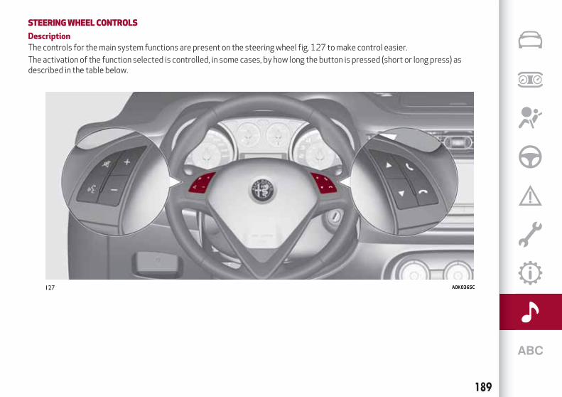
STEERINGWHEEL CONTROLS
Description
The controls for the main system functions are present on the steering wheel fig. 127 to make control easier.
The activation of the function selected is controlled, in some cases, by how long the button is pressed (short or long press) asdescribed in the table below.
127 A0K0365C
189

STEERINGWHEEL CONTROL SUMMARYTABLE
Button Interaction
Acceptance of incoming call
Acceptance of the second incoming call and putting the active call on hold
Activation of voice recognition for Phone function
Interruption of the voice message in order to give a new voice command
Interruption of voice recognition
Rejection of incoming call
Ending of call in progress
Deactivate/reactivate the microphone during a phone conversation
Activation/deactivation of the SD (for versions/markets, where provided), USB/iPod,Bluetooth® sourcePause
Activation/deactivation of radio Mute function
+/- Adjustment of the audio volume: hands-free, text message reader, voice announcements and music sources
Activation of voice recognition
Interruption of the voice message in order to give a new voice command
Interruption of voice recognition
Short press (Radio mode): selection of next/previous station
Long press (Radio mode): scan higher/lower frequencies until released
Short press (SD, for versions/markets, where provided, USB/iPod,Bluetooth®mode): selection ofprevious/next track
Long press (SD, for versions/markets, where provided, USB/iPod,Bluetooth®mode): fast forward/rewinduntil released
190
MU
LTIM
ED
IA

SWITCHINGTHE SYSTEMON/OFFThe system is switched on/off bypressing the (ON/OFF) button/knob.
Turn the button/knob clockwise toincrease the radio volume oranticlockwise to decrease it.
RADIO (TUNER)MODEPress the RADIO button on the frontpanel to activate radio mode.
Selecting a frequency band
The various tuning modes can beselected by touching the “AM”, “FM” and“DAB” (for versions/markets whereprovided) on the display.
Indications on display
After the desired radio station isselected, the following information isshown on the display:
At the top: display of the stored radiostation (preset) list. The station beinglistened to is highlighted.
In themiddle: display of the currentradio station’s name and the buttons forselecting the band.
At the bottom: radio station selection,tuning and audio settings.
Searching for the previous/next radiostation
To search for the desired radio station,rotate the BROWSE ENTER button/knob,
press the or buttons or usethe steering wheel controls .
Previous/next radio station fast search
Hold down buttons or on thedisplay: when the button is released, thefirst tunable radio station will bedisplayed.
Tuning the radio (AM/FM)
Press the “tune” button on the display andthen enter the frequency of the radiostation on the keyboard on the display.
In this mode, use buttons and tofine-tune the frequency.
To delete an incorrect number (and enterthe correct station number) press the
(Delete) button.
After the last digit of the station isentered, the screen is deactivated andthe system tunes to the selected stationautomatically.
The screen disappears automaticallyafter 5 seconds or manually by pressingthe "OK" or "X" (Delete) button.
Exit the "Direct Tune" screen
Press the “Exit” or “Radio” button on thedisplay to return to the system’s mainscreen.
DAB Radio
(for versions/markets, where provided)
Once DAB radio mode is selected, the
information on the current station isdisplayed and the following functions.
Within each list, the "ABC" button allowsthe user to skip to the desired letter inthe list.
The "Browse" button is used to display:the list of all DAB stations;the list of stations filtered by "Genres";the list of stations filtered by
"Ensembles" (broadcast group).
Within each list, the "ABC" button allowsthe user to skip to the desired letter inthe list.
Setting the presets
Presets are available in all system modesand are activated by touching one of thepreset buttons located in the upper areaof the display.
If you are tuned to a radio station thatyou wish to store, hold down the buttonon the display which corresponds to thedesired preset or until an acousticconfirmation signal is emitted.
The system can store up to 12 radiostations in each mode: 4 radio stationsare displayed in the upper area.
Press the "browse" button on the displayto show all the radio stations stored inthe selected frequency band.
Audio
To access the "Audio" menu, press the"audio" button on the display.
191

The following adjustments can be carriedout using the "Audio" menu:
"Balance/Fader" (left/right andfront/rear audio balance adjustment);
"Equalizer" (for versions/markets,where provided): to adjust the bass,medium and treble settings;
"Volume/Speed" (excluding versionswith Hi-Fi system) speed-dependentautomatic volume adjustment;
"Loudness" (for versions/markets,where provided): improves audio qualityat low volumes;
"Auto-On Radio": provides the optionsof radio on, radio off or restore statuswhen the ignition key was last turned toSTOP.
MEDIAMODE
This chapter describes the interactionmodes related to operation of the SDcard (for versions/markets, whereprovided) and theBluetooth®, AUX andUSB/iPod devices.Press the “select source” button to selectthe desired audio source from thoseavailable.
Change track (next/previous)
Briefly press the button or turn theBROWSE ENTER button/knob clockwiseto play the next track or briefly press the
button or turn the BROWSE ENTERbutton/knob anticlockwise to return tothe beginning of the selected track or to
the beginning of the previous track if thishas been played for less than 8 seconds.
Fast forward/rewind through tracks
Press and hold down the button tofast forward the selected track or keepthe button pressed to fast rewindthe track.
Track selection (Browse)
NOTEBluetooth® devices do not offerthe possibility of scrolling through tracksusing the above categories.NOTE This button might be disabled forsomeApple®devices.Press the "Browse" button to activatethis function on the source being played.
Turn the BROWSE ENTER button/knobto select the desired category and thenpress the button/knob to confirm theselection.
Press the "X" button to cancel thefunction.
Track information display
Press the "Info" button to display theinformation on the track being listened tofor devices that support the function.
Press the "X" button to exit the screen.
Shuffle
Press the ">" button then the "Shuffle"button to play the tracks on the SD card(for versions/markets, where provided),or on the USB/iPod orBluetooth®
devices in a random order.Press the "Shuffle" button again todeactivate the function.
Repeat
Press the ">" button then the "Repeat"button to activate the function.
Press the "Repeat" button again todeactivate the function.
Bluetooth®SOURCE
Pairing aBluetooth® deviceactivate theBluetooth® function on
the device;press the MEDIA button on the front
panel;if the “Media” source is active, press he
“select resource” buttonselect theBluetooth®Media source;press the "Add Device" button;look forUconnect™ on theBluetooth®
audio device.when requested by the audio device,
enter the PIN code shown on the systemdisplay or confirm on the device the PINdisplayed;
select “Yes” or “No” when asked if youwant to set theBluetooth® audio deviceas the favourite.
an audio device can also be paired bypressing the button on the front paneland selecting "Phone/Bluetooth”.
192
MU
LTIM
ED
IA

USB/iPod SUPPORT150)
If a USB/iPod device is inserted with thesystem on, this starts playing the trackspresent on the device.
WARNING
150)When inserting a device (USB or iPod)in theUSBport, make sure that it does notobstruct the operation of the handbrakelever.
SD Card SUPPORT(for versions/markets, where provided)
The system is equipped with an SD andSD-HC card reader able to read/managecards with SPI technology.
To activate SD mode, insert an SD Card inthe dedicated slot on the vehicle.
AUX source151)
When a device is inserted using the AUXoutput socket the system startsreproducing the AUX source connected,if it is already being played.
Adjust the volume using thebutton/knob on the front panel or
using the volume adjustment control onthe connected device.
IMPORTANT: the functions of the device
connected to the AUX socket are directlymanaged by the device itself.
WARNING
151)When inserting a device in the AUXsocket, make sure that it does not obstructthe operation of the handbrake lever.
PHONEMODE
Phone mode activation
Press the PHONE button on the frontpanel to activate the Phone mode.
A message on the display confirmsconnection of the phone.
NOTE To consult the list of mobile phonesand supported functions, visit thewww.driveuconnect.eu website
Main functions
Use the buttons on the display to:dial the phone number (using the
graphic keypad on the display);display and call the contacts in the
mobile phone phonebook;display and call contacts from the
registers of previous calls;pair up to 10 phones/audio devices to
make access and connection easier andquicker;
transfer calls from the system to themobile phone and vice versa anddeactivate the microphone audio forprivate conversations.
To consult the list of mobile phones andsupported functions, visit thewww.driveuconnect.eu website or callCustomer Service (the number may varydepending on the country: please refer tothe reference table in the "CustomerService number list" section herein).
Pairing a mobile phone
To pair the mobile phone, proceed asfollows:
activate theBluetooth® function onthe mobile phone;
press the PHONE button on the frontpanel;
if no phone is paired with the systemyet, the display shows a dedicatedscreen;
select "Yes" to start the pairingprocedure, then search for theUconnect™ device on the mobile phone;
when prompted by the mobile phone,use its keypad to enter the PIN codeshown on the system display or confirmon the mobile phone the PIN displayed;
from the "Phone" screen you canalways pair a mobile phone by pressingthe "Settings" button: press the "AddDevice" button and proceed as describedabove;
select "Yes" or “No” at the request topair the mobile phone as the preferreddevice;
NOTE After updating the phone software,
193

for proper operation, it is recommendedto remove the phone from the list ofdevices linked to the radio, delete theprevious system pairing also from the listof Bluetooth devices on the phone andmake a new pairing.
Transferring phone data (phonebookand recent calls)
If your mobile phone has a function forsending the phonebook viaBluetooth®technology.Answer "Yes" when asked to copy thephonebook to the system.
Answer "No" to carry out the operationlater on.
Making a phone call
The operations described below can onlybe accessed if supported by the mobilephone in use.
A call can be made by:selecting the icon (mobile phone
phonebook);selecting "Recent Calls";selecting the icon (Keypad);pressing the "Redial" button.
Handling an incoming call
The buttons on the display allow thefollowing phone call functions to bemanaged:
To answer a call: press the "Answer"button or the button on the steeringwheel controls;
To end a call: press the "Ignore" buttonor the button on the steering wheelcontrols;
Ignore;Put on hold/resume;Deactivate/activate the microphone;Transfer the call;Switch from one call to the other;Conference/merge two active calls.
Text message reader
To use this function the mobile phonemust support the SMS exchange functionthroughBluetooth™.
If this function is not supported by thephone, the corresponding button isdeactivated (grey).
When a text message is received, thedisplay will show a screen where theoptions "Listen", "Call" or "Ignore" can beselected.
The list of SMS messages received fromthe mobile phone can be accessed bypressing the button.
NOTE Some mobile phones may not takethe SMS delivery confirmation settingsinto account when interfacing withUconnect™. If an SMS message is sent viaUconnect™, the user could face anadditional cost, without any warning, dueto the SMS delivery confirmation requestsent by the phone. For any problemsrelated to the above, contact yourtelephone service provider.
Siri Eyes Free
Siri allows you to use your voice to sendtext message, manage media sources,phone calls and much more. You can keepyour eyes on the road and your hands onthe steering wheel, while using Siri toperform other useful operations.
Press the button on the steering wheel(long press) to activate Siri. When youhear a double beep you can begin tointeract with Siri.
NOTE the Siri enabled device must bepaired with theUconnect™ system usingthe pairing procedure (see the relatedparagraph).
Speak clearly with a normal rhythm andvolume.
Siri is available on the iPhone 4S andsubsequent versions.
NAVIGATIONMODE
Main navigation menu
IMPORTANT The volume of the navigatorcan only be adjusted while the voiceguidance instructions are beingreproduced by operating button/knob
(ON/OFF).
To activate the main navigation menu,press the NAV button on the front panel,then press one of the following buttonson the screen.
"Where to?": find or navigate to thedestination;
194
MU
LTIM
ED
IA

"View map": display the map;"Info": display all the navigation
information;"Emergency": search for Hospitals,
Police stations, etc.
The following graphic buttons are alsopresent:
“Settings”: choose the systemsettings;
"Stop": interrupt navigation;“Reroute”: possible diversions from
the set route;"Repeat": recalculate route to the last
direction selected.
Where to?
From the Main Navigation Menu, pressthe "Where To?" button then select one ofthe following options to reach thedestination:
“Address": find a destination byentering the street name and number;
“Recent”: recall a previous destination;"Point of interest": plan a journey to a
(POI) chosen from a list of locales andpublic places;
"Favourites": recall previously storedaddresses and destinations;
"Crossing": travel to a road junction;"Go Home": plan or confirm a journey
to your home address;"Trip": plan a new journey or recall one
which is already stored;
"City Centre": travel to the centre ofthe specified city;
"Closest Towns": travel to a nearbytown.
"Trips": store the route that you aretaking in order to recall it later on.
You can also select a destination byentering the geographical coordinates,selecting a point on the map or by its POI(Point of Interest) number.
ViewMap
Press the "View Map" button in the mainNavigation Menu to display the maprelative to the current position.
When the display shows the map, thefollowing options are available:
"Menu": return to the main NavigationMenu;
"+/–": map zoom;Arrival time/Time to destination
time/Distances": display one of thefollowing options: "Arrival time", "Time todestination", "Distances" (duringnavigation only);
“Turn list”: displays a list of thepossible diversions along the route (onlywhile navigating);
"Options": allows you to change themap view, change the navigator settings,repeat the last direction, view the list ofdirections and interrupt navigation.
Settings Menu
The following settings are available forthe Map:
"Map configuration": customization ofthe map display mode;
"Speed limit": activation/deactivationof the audible warning given onexceeding the speed limit and speed limitvalue setting;
"Guide": navigation customization;"DMS": change display of the GPS
signal;"TMC Station List": display the list of
radio stations that transmit TMC (TrafficMessage Channel) traffic information.
Information
Press the "Information" button in themain Navigation Menu to select from thefollowing information:
Traffic;Where am I?: display your current
position on the map;Trip Computer: summarises the main
information about the current route.
Emergency
Press the "Emergency" button to selectand navigate to the nearest hospital orpolice station.
195
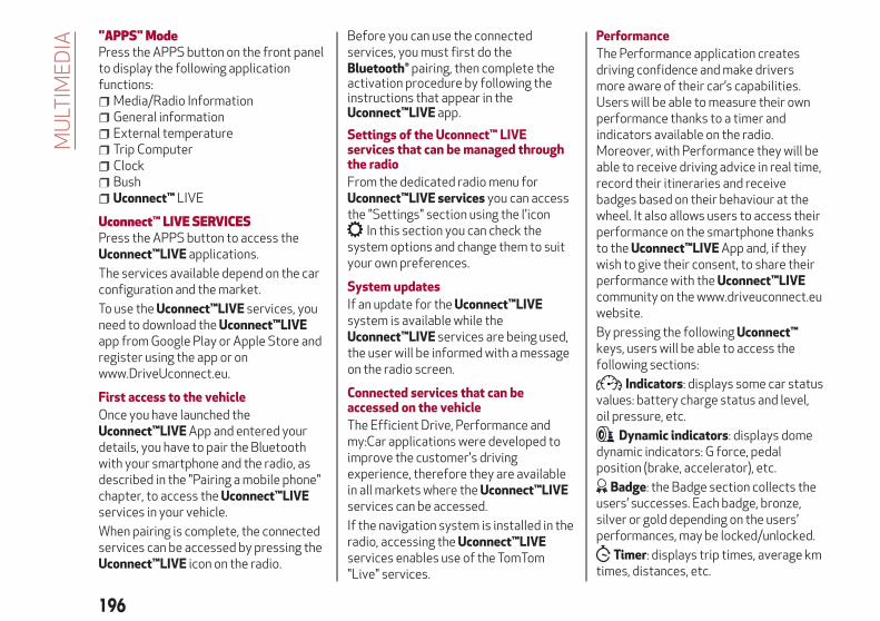
"APPS"ModePress the APPS button on the front panelto display the following applicationfunctions:
Media/Radio InformationGeneral informationExternal temperatureTrip ComputerClockBushUconnect™ LIVE
Uconnect™ LIVE SERVICESPress the APPS button to access theUconnect™LIVE applications.
The services available depend on the carconfiguration and the market.
To use theUconnect™LIVE services, youneed to download theUconnect™LIVEapp from Google Play or Apple Store andregister using the app or onwww.DriveUconnect.eu.
First access to the vehicle
Once you have launched theUconnect™LIVEApp and entered yourdetails, you have to pair the Bluetoothwith your smartphone and the radio, asdescribed in the "Pairing a mobile phone"chapter, to access theUconnect™LIVEservices in your vehicle.
When pairing is complete, the connectedservices can be accessed by pressing theUconnect™LIVE icon on the radio.
Before you can use the connectedservices, you must first do theBluetooth® pairing, then complete theactivation procedure by following theinstructions that appear in theUconnect™LIVE app.
Settings of the Uconnect™ LIVEservices that can be managed throughthe radio
From the dedicated radio menu forUconnect™LIVE services you can accessthe "Settings" section using the l'icon
In this section you can check thesystem options and change them to suityour own preferences.
System updates
If an update for theUconnect™LIVEsystem is available while theUconnect™LIVE services are being used,the user will be informed with a messageon the radio screen.
Connected services that can beaccessed on the vehicle
The Efficient Drive, Performance andmy:Car applications were developed toimprove the customer's drivingexperience, therefore they are availablein all markets where theUconnect™LIVEservices can be accessed.
If the navigation system is installed in theradio, accessing theUconnect™LIVEservices enables use of the TomTom"Live" services.
Performance
The Performance application createsdriving confidence and make driversmore aware of their car’s capabilities.Users will be able to measure their ownperformance thanks to a timer andindicators available on the radio.Moreover, with Performance they will beable to receive driving advice in real time,record their itineraries and receivebadges based on their behaviour at thewheel. It also allows users to access theirperformance on the smartphone thanksto theUconnect™LIVEApp and, if theywish to give their consent, to share theirperformance with theUconnect™LIVEcommunity on the www.driveuconnect.euwebsite.
By pressing the followingUconnect™keys, users will be able to access thefollowing sections:
Indicators: displays some car statusvalues: battery charge status and level,oil pressure, etc.
Dynamic indicators: displays domedynamic indicators: G force, pedalposition (brake, accelerator), etc.
Badge: the Badge section collects theusers’ successes. Each badge, bronze,silver or gold depending on the users’performances, may be locked/unlocked.
Timer: displays trip times, average kmtimes, distances, etc.
196
MU
LTIM
ED
IA

Routes: selects one of variousitineraries, and to start the drivingexperience, displays the itinerary mapand accesses all the performancesobtained.A B My itineraries: creates a customiseditinerary or selects an itinerary fromthose created previously and stores theGPS tracking from the starting point “ A “to the destination “ B “.
Settings: selects the measurementunits and performs backup.
Recording and transferring trip data
The trip data can be stored in the systemmemory and made available outside thecar thanks to theUconnect™LIVEApp.This allows users to view the collecteddata later, showing the overall trip dataanalysis. Further information is availableat www.DriveUconnect.eu.
For full access to the service’sfunctionality, users must allow their datato be recorded on-board the car. Thefollowing icon is the user’sgeo-location indicator. ThroughUconnect™LIVE, users can choose toenable detection of their location and toshare their data with the community.
Efficient Drive
The Efficient Drive application allows youto display your driving behaviour in realtime, in order to help you reach a more
efficient driving style as far asconsumption and emissions areconcerned.
Driving style is evaluated by means offour indices which monitor the followingparameters: acceleration, deceleration,gearchange, speed
Display of the Efficient Drive
Press the Efficient Drive button tointeract with the function.
A screen will appear on the radio showing4 indices: Acceleration, Deceleration,Speed and Gear. These indices are greyuntil the system has enough data toevaluate the driving style. Once sufficientdata are available, the indices will have5 colours depending on the evaluation:dark green (very good), light green,yellow, orange and red (very bad).
In the event of extended inactivity, thedisplay will show the average of theindices until that moment (the "Averageindex"), then the indices will be colouredagain in real time as soon as the vehicle isrestarted.
my:Car
my:Car allows you to keep the "health" ofyour vehicle always under control.
my:Car can detect malfunction in realtime and inform the user about the expiry
of the servicing interval. Press the"my:Car" button to interact with theapplication.
The display will show a screen with the"care:Index" section, which provides allthe detailed information about the statusof the vehicle. Press the "Activewarnings" button to show (if present) thedetails of the vehicle's faults whichcaused a warning light to switch on.
SETTINGSPress the button on the front panel todisplay the main "Settings" menu
NOTE The menu items displayed varyaccording to the versions.
Display;DNA messages;ClockSafety & Driving Assist.Lights;Doors and Door lock;Vehicle Shutdown Vehicle;Audio;Phone/Bluetooth;Radio Setup;System Information.Restore Default Settings;Clear personal data;
197

DRIVINGMODE (DNA) INFORMATIONACTIVATION
This function can be used to selectwhether to show Alfa DNA messages("ON") or not ("OFF") on the display.
VOICE COMMANDS
Using voice commands
The button on the steering wheelactivates the “Phone” voice recognitionmode, there is a "beep" and the displayshows a suggestion screen inviting theuser to say a command.
If the button is pressed during asystem voice message, it activates the“Radio/Media” voice recognition modethat controls the radio and heUSB/iPod/SD players (forversions/markets, where provided).
Please follow the suggestions below tobe sure that the voice commands arealways recognised by the system:
speak at a normal volume;always wait for the "beep" (warning
sound) before speaking;if possible, try and keep the noise in
the passenger compartment to aminimum. It is also advisable to close thewindows and sunroof (forversions/markets, where provided).
for optimum operation, it is advisableto close the windows and the sun roof(for versions/markets, where provided)to avoid external interference;
WARNING Voice commands must alwaysbe given in safe driving conditions, incompliance with the laws in force in thecountry where you are driving and usingthe mobile phone correctly.
Multiple choice
In a few specific cases the system cannotunambiguously identify the given voicecommand and asks the user to choosebetween a maximum of four alternatives.
The system will propose a numbered listof the available alternatives, asking theuser to say the associated number.
List of voice commands
GLOBAL voice commands:HELPCANCELREPEATVOICE PROMPTS
PHONE voice commands:CALL <contact>DIAL <number>REDIALCALL BACKLAST CALLSOUTGOING CALLSMISSED CALLSINCOMING CALLSSHOW PHONEBOOKSEARCH <contact>SHOW MESSAGES
TEXTMESSAGE voice commands:SEND A TEXT MESSAGE TO <number>SEND TEXT MESSAGE TO <contact>
ON <mobile>SHOW MESSAGES
HANDS FREE CALLING voice commands:SEND TO NUMBER <number>SEND <contact>TRANSFERSHOW MESSAGES
RADIO AM/FM/DAB voice commands:TUNE TO <frequency><band> /
<preset station>TUNE TO DAB CHANNEL <preset
station>
MEDIA voice commands:PLAY TRACK <track>PLAY ALBUM <album>PLAY ARTIST <artist>PLAY GENRE <genre>PLAY PLAYLIST <playlist>PLAY PODCAST <podcast>PLAY AUDIOBOOK <audiobook>PLAY TRACK NUMBER <track
number>SELECT SOURCE <source>BROWSE <album>
NAVIGATION voice commands:GO HOMESHOW MAPFIND ADDRESSCLEAR ROUTERECENT DESTINATIONS
198
MU
LTIM
ED
IA

REPEAT INSTRUCTION
ANTITHEFTPROTECTIONThe system is equipped with an anti-theftprotection system based on theexchange of information with theelectronic control unit (Body Computer)on the vehicle.
This guarantees maximum safety andprevents the secret code from beingentered after the power supply has beendisconnected.
If necessary contact an Alfa RomeoDealership.
199

Ask your mechanic for
It’s in the heart of your engine.
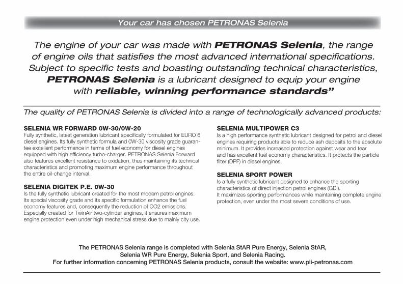
Your car has chosen PETRONAS Selenia
The quality of PETRONAS Selenia is divided into a range of technologically advanced products:
SELENIA WR FORWARD 0W-30/0W-20Fully synthetic, latest generation lubricant specifically formulated for EURO 6 diesel engines. Its fully synthetic formula and 0W-30 viscosity grade guaran-tee excellent performance in terms of fuel economy for diesel engines equipped with high efficiency turbo-charger. PETRONAS Selenia Forward also features excellent resistance to oxidation, thus maintaining its technical characteristics and promoting maximum engine performance throughout the entire oil-change interval.
SELENIA DIGITEK P.E. 0W-30Is the fully synthetic lubricant created for the most modern petrol engines. Its special viscosity grade and its specific formulation enhance the fuel economy features and, consequently the reduction of CO2 emissions. Especially created for TwinAir two-cylinder engines, it ensures maximum engine protection even under high mechanical stress due to mainly city use.
SELENIA MULTIPOWER C3Is a high performance synthetic lubricant designed for petrol and diesel engines requiring products able to reduce ash deposits to the absoluteminimum. It provides increased protection against wear and tear and has excellent fuel economy characteristics. It protects the particle filter (DPF) in diesel engines.
SELENIA SPORT POWERIs a fully synthetic lubricant designed to enhance the sporting characteristics of direct injection petrol engines (GDI). It maximizes sporting performances while maintaining complete engine protection, even under the most severe conditions of use.
The PETRONAS Selenia range is completed with Selenia StAR Pure Energy, Selenia StAR, Selenia WR Pure Energy, Selenia Sport, and Selenia Racing.
For further information concerning PETRONAS Selenia products, consult the website: www.pli-petronas.com
The engine of your car was made with PETRONAS Selenia, the range of engine oils that satisfies the most advanced international specifications. Subject to specific tests and boasting outstanding technical characteristics,
PETRONAS Selenia is a lubricant designed to equip your engine with reliable, winning performance standards”

Mopar Vehicle Protection offers a series of service contracts that are designed to give all our customers thepleasure of driving their vehicle without any hitch's and concerns.
Our product portfolio consists of a wide and flexible range of extended warranty and maintenance plansendorsed by FCA. Each with a series of different coverage tiers, in terms of durability and mileage, built to
accommodate you’re driving needs.Service contracts are made by experts that know every part of your vehicle, and commit themselves
to maintain it in tip top conditions. Our knowledge and passion is tailored around designing products that promises all our drivers “worry-free driving”.
Only with Mopar Vehicle Protection you are ensured that all service operations are performed by highly qualified and specialized technicians in authorized FCA repair facilities, using the right tools,
equipment and only original parts, all over Europe.Check which Service Contract plans are available on your market today and choose the
Service Contract that suits your driving habits best.Ask your local dealer for further information.
MAINTAIN YOUR VEHICLE IN TIP TOP CONDITIONS WITH

NOTES


INDEX"Electronic Q2" system ("E-Q2") . . . .61
"Follow Me Home" device . . . . . . . . .19
“Alfa DNA” system. . . . . . . . . . . . .31
“Smart Bag” system (multistagefront airbags) . . . . . . . . . . . . . .75
ABS system . . . . . . . . . . . . . . . .60
Active safety systems. . . . . . . . . . .60
AFS adaptive lights (AdaptiveFrontlight System) . . . . . . . . . . .19
Air cleaner . . . . . . . . . . . . . . . . .139
Alarm system . . . . . . . . . . . . . . . .11
Alfa Romeo Code system . . . . . . . . .10
ALFA TCT . . . . . . . . . . . . . . . . . .83
Key removal . . . . . . . . . . . . . .117
ASR (AntiSlip Regulation) system . . . .60
Automatic dual-zone climatecontrol system . . . . . . . . . . . . .24
AUX source . . . . . . . . . . . . .181 ,193
Battery . . . . . . . . . . . . . . . . . .140
advice for extending its life . . . . .140
replacement . . . . . . . . . . . . . .140
Battery (recharging) . . . . . . . . . . .138
Bluetooth®. . . . . . . . . . . . . .181 ,192
Bodyworkmaintenance . . . . . . . . . . . . . .142
Boot . . . . . . . . . . . . . . . . . . . . .30
Brakesbrake fluid level . . . . . . . . . . . .137
Carrying children safely . . . . . . . . .68
CBC (Cornering Brake Control)system . . . . . . . . . . . . . . . . . .61
Changing a wheel . . . . . . . . . . . . .110
Checking levels . . . . . . . . . . . . . .133
Cleaning and maintenancebodywork . . . . . . . . . . . . . . .142
car interior . . . . . . . . . . . . . . .143
front headlights . . . . . . . . . . . .143
leather parts . . . . . . . . . . . . . .144
leather seats . . . . . . . . . . . . . .143
plastic and coated parts . . . . . . .143
seats and fabric parts . . . . . . . .143
Climate control . . . . . . . . . . . . . . .22
CO2 emissions . . . . . . . . . . . . . .170
Control buttons. . . . . . . . . . . . . . .38
Control panel and on-boardinstruments . . . . . . . . . . . . . . .36
Reconfigurable multifunctiondisplay . . . . . . . . . . . . . . . . . .36
CONTROLSFront panel control summarytable . . . . . . . . . . . . . . . . . .188
Courtesy lightsFront ceiling light . . . . . . . . . . . .20
Cruise Control . . . . . . . . . . . . . . .89
Daytime running lights (DRL) . . . . . .17
Diesel filter . . . . . . . . . . . . . . . .139
Dimensions . . . . . . . . . . . . . . . .156
Dipped headlightsbulb replacement . . . . . . . . . . .100
Direction indicators . . . . . . . . . . . .19
“Lane change” function . . . . . . . .19
bulb replacement . . . . . . . .100 ,101
Display . . . . . . . . . . . . . . . . . . . .38
Doors. . . . . . . . . . . . . . . . . . . . .11
Child safety device . . . . . . . . . . .12
Door central locking/unlocking . . . .11
DST system (Dynamic SteeringTorque) . . . . . . . . . . . . . . . . . .60
Dusk sensor . . . . . . . . . . . . . . . . .17
EBD system . . . . . . . . . . . . . . . .60
Electric sunroof . . . . . . . . . . . . . .27
Electric windows . . . . . . . . . . . . . .26
Controls . . . . . . . . . . . . . . . . .26
Engine . . . . . . . . . . . . . . . . . . .148
engine coolant level . . . . . . . . .137
marking . . . . . . . . . . . . . . . . .147
Engine bonnet . . . . . . . . . . . . . . .29
Closing . . . . . . . . . . . . . . . . . .29
Opening . . . . . . . . . . . . . . . . .29
Engine compartmentwashing . . . . . . . . . . . . . . . . .143
Engine oilconsumption . . . . . . . . . . . . . .137
level check . . . . . . . . . . . . . . .137
ESC (Electronic Stability Control)system . . . . . . . . . . . . . . . . . .60
External courtesy lights. . . . . . . . . .19

External lights . . . . . . . . . . . . . . .17
Fitting "Universal" child restraint
system . . . . . . . . . . . . . . . . . .69
Fix&Go Automatic kit . . . . . . . . . .113
Flashing the headlights . . . . . . . . . .18
Fluids and lubricants . . . . . . . . . . .164
Front airbag driver's side . . . . . . . . .75
Front airbags . . . . . . . . . . . . . . . .75
Front fog lights . . . . . . . . . . . . . . .18
bulb replacement . . . . . . . . . . .101
Fuel consumption . . . . . . . . . . . .168
Fuel cut-off system . . . . . . . . . . .117
Fuel tank cap . . . . . . . . . . . . . . . .93
Fuses (replacement) . . . . . . . . . . .102
Gear Shift Indicator . . . . . . . . . . . .38
Handbrake . . . . . . . . . . . . . . . . .83
Hazard warning lights . . . . . . . . . . .96
HBA system . . . . . . . . . . . . . . . . .60
Head restraints . . . . . . . . . . . . . . .15
Front head restraints . . . . . . . . .15
Rear head restraints . . . . . . . . . .15
Headlights . . . . . . . . . . . . . . . . . .31
Adjusting the headlights abroad . . .31
Headlight alignment corrector . . . .18
Light beam direction . . . . . . . . . .31
Hill Holder system . . . . . . . . . . . . .61
Identification datachassis marking . . . . . . . . . . . .147
engine marking . . . . . . . . . . . .147
identification data plate . . . . . . .146
Ignition device . . . . . . . . . . . . . . . .9
Steering lock . . . . . . . . . . . . . . .9
Installing a Universal Isofix childrestraint system . . . . . . . . . . . .72
Interior lights . . . . . . . . . . . . . . . .20
Interiors (cleaning) . . . . . . . . . . . .143
Isofix child restraint system setup . . .72
iTPMS System (indirect TyrePressure Monitoring System) . . . .62
Jack. . . . . . . . . . . . . . . . . . . . .110
Jump starting . . . . . . . . . . . . . . .116
Lifting the vehicle . . . . . . . . . . . .142
Light bulbstypes of bulbs . . . . . . . . . . . . . .97
LPG version . . . . . . . . . . . . . . . . .32
Luggage compartmentBag hooks . . . . . . . . . . . . . . . .30
Closing the luggage compartment. . . . . . . . . . . . . . . . . . . . . . .30
Emergency luggage compartmentopening . . . . . . . . . . . . . . . . . .30
Extending the luggagecompartment . . . . . . . . . . . . . .30
Luggage compartmentinitialisation . . . . . . . . . . . . . . .30
Luggage retaining net . . . . . . . . .30
Opening the boot . . . . . . . . . . . .30
Main beam headlights . . . . . . . . . .18
bulb replacement . . . . . . . . . . .100
Manual climate control . . . . . . . . . .22
Menu items . . . . . . . . . . . . . . . . .40
MSR system . . . . . . . . . . . . . . . .60
Multimedia"APPS" Mode . . . . . . . . . .183 ,196
Anti-theft . . . . . . . . . . . .185 ,199
CD . . . . . . . . . . . . . . . . . . . .181
Controls on the front panel(Uconnect™ 5" Radio LIVE) . . . . .175
Controls on the front panel(Uconnect™ 6.5" Radio Nav LIVE) .187
Navigation mode . . . . . . . . . . .194
Phone mode . . . . . . . . . . .182 ,193
Power on/off . . . . . . . . . .179 ,191
SD Card support . . . . . . . . . . .193
Settings . . . . . . . . . . . . .184 ,197
Uconnect™ LIVE Services . . .183 ,196
Voice commands . . . . . . . .184 ,198
Number plate lights
bulb replacement . . . . . . . . . . .102
Parking lights. . . . . . . . . . . . . . . .17
Parking sensors . . . . . . . . . . . . . .90
Parking the vehicle . . . . . . . . . . . . .83
Handbrake . . . . . . . . . . . . . . . .83
Passenger side front airbag . . . . . . .75
Performance . . . . . . . . . . . . . . .167
Pollen filter . . . . . . . . . . . . . . . .139
Pre-Fill system (RAB - Ready AlertBrake). . . . . . . . . . . . . . . . . . .61
IND
EX

Pre-tensioners . . . . . . . . . . . . . . .66
Load limiters . . . . . . . . . . . . . .66
Radio . . . . . . . . . . . . . . . .179 ,191
Rain sensor . . . . . . . . . . . . . . . . .21
Rear fog lights . . . . . . . . . . . . . . .18
Rear fog lights/reversing lightsbulb replacement . . . . . . . . . . .101
Rear view mirrors . . . . . . . . . . . . .16
Door mirrors . . . . . . . . . . . . . . .16
Rear window washerrear window washer fluid level . . .137
Rear window wiper/washer . . . . . . .21
Reconfigurable multifunctiondisplay . . . . . . . . . . . . . . . . . .38
Refuelling . . . . . . . . . . . . . . . . .160
Refuelling capacity . . . . . . . . . . . .93
Refuelling the vehicle . . . . . . . . .92 ,93
Replacing a bulb . . . . . . . . . . . . . .96
exterior lights . . . . . . . . . . . . .100
General instructions . . . . . . . . . .96
Rims and tyres provided . . . . . . . .154
Safe Lock (device) . . . . . . . . . . . . .8
SBR system (Seat Belt Reminder). . . .65
Scheduled servicing . . . . . . . . . . .122
Scheduled Servicing Plan . . . . . . . .123
Screen wiper/washer . . . . . . . . . . .20
“Smart washing” function . . . . . . .21
Seat belts . . . . . . . . . . . . . . . . . .64
Use . . . . . . . . . . . . . . . . . . . .64
Seats . . . . . . . . . . . . . . . . . . . . .13
Front seats . . . . . . . . . . . . . . .13
Rear seats . . . . . . . . . . . . . . . .14
Servicing and maintenanceDemanding use of the car . . . . . .132
periodic checks . . . . . . . . . . . .132
Servicing proceduresHeadlight washer . . . . . . . . . . .140
Nozzles . . . . . . . . . . . . . . . . .139
Setup menu . . . . . . . . . . . . . . . . .39
Side airbags (Side bags - Windowbags) . . . . . . . . . . . . . . . . . . .79
Side bags (front side airbags) . . . . . .79
Side lights/brake lightsbulb replacement . . . . . . . . . . .101
Side lights/daytime running lights(DRL)bulb replacement . . . . . . . . . . .100
Side lights/dipped beamheadlights . . . . . . . . . . . . . . . .17
Start&Stop system . . . . . . . . . . . .87
Starting the engine . . . . . . . . .82 ,116
Bump starting . . . . . . . . . . . . .116
Jump starting . . . . . . . . . . . . .116
Steering lock . . . . . . . . . . . . . . . . .9
Steering wheel . . . . . . . . . . . . . . .15
Steering wheel controls . . . . .177 ,189
Technical data . . . . . . . . . . . . . .146
The keys . . . . . . . . . . . . . . . . . . . .8
Key with remote control . . . . . . . . .8
Mechanical key . . . . . . . . . . . . . .8
Third brake lightsbulb replacement . . . . . . . . . . .102
Towing the vehicle . . . . . . . . . . . .119
Attaching the tow ring . . . . . . . .119
Towing trailers . . . . . . . . . . . . . . .92
Installing a tow hook . . . . . . . . . .92
Trip Computer . . . . . . . . . . . . . . .41
TyresFix&Go Automatic (kit) . . . . . . .113
inflation pressures . . . . . . . . . .155
USB/iPod support . . . . . . . .181 ,193
Using the transmission . . . . . . . . . .86
Vehicle changes/alterations . . . . . . .4
Warning lights and messages . . . . . .42
Weights . . . . . . . . . . . . . . . . . .157
Wheels . . . . . . . . . . . . . . . . . . .154
Wheels and tyreschanging a wheel . . . . . . . . . . .110
tyre inflation pressure . . . . . . . .155
Window bags (side airbags for headprotection) . . . . . . . . . . . . . . . .79
Windows (cleaning) . . . . . . . . . . .142
Windscreen washerwindscreen washer fluid level . . .137
Windscreen/rear window wiper . . . . .20

FCA Italy S.p.A. - MOPAR - Technical Services - Service EngineeringLargo Senatore G. Agnelli, 3 - 10040 Volvera - Turin (Italy)
Print no. 604.38.862 - 09/2016 - 3 Edition

This Owner Handbook illustrates the operating instructions of the car.
Alfa Romeo provides a dedicated section available in electronic format for enthusiasts who want insights, curiosities and detailed information about the features and functions of the car.
ONLINE OWNER HANDBOOK
The symbol appears in the Owner Handbook next to topics for which updates are available.
Go to elum.alfaromeo.com where you will find all the details of the Owner Handbook.
Alternatively, to access this information, go to the Internet website at http://aftersales.fiat.com/elum/.
The eLUM website is free and conveniently allows you to browse the on-board documents of all other models of the Group, among many other things.
Have a nice read and happy motoring!
ALFA ROMEO GENUINE SPARE PARTS AND ACCESSORIES
PERFECT FOR YOUR VEHICLE, RIGHT DOWN TO THE SMALLEST DETAIL
The Alfa Romeo Genuine Spare Parts and Accessories follow the rigid component engineering and manufacturing specifi cations used in the assembly line to meet the technical specifi cations of your new Alfa Romeo and to enhance its style and performance. They undergo strict approval tests and quality controls to ensure they comply with safety and environmental standards.
All of the components on your new Alfa Romeo, from the smallest bulb to the most complex mechanical, electrical and electronic systems, are designed to work in harmony and guarantee you a comfortable and safe drive, in full respect for the environment. The Genuine Accessories fully enhance the style of your new vehicle.
Entrust the experience and quality of Alfa Romeo Dealerships to fi nd the full range of Alfa Romeo Genuine Spare Parts and Accessories.
Find your nearest Dealership on www.alfaromeo.com
retro cop alfa giulia EN.qxp_500 UM ITA 16/12/15 09:26 Pagina 1

OWNER HANDBOOK
ENGLISH
cop lum giulia GB.indd 1cop lum giulia GB.indd 1 11/12/15 10:5811/12/15 10:58