9300190901_v1_7750 sr-12 installation guide.pdf
TRANSCRIPT
Alcatel-LucentService Router 7 7 5 0 S R - 1 2 I n s t a l l a t i o n G u i d e
93-0019-09-01
93-0019-09-01
Alcatel-Lucent ProprietaryThis document contains proprietary information of Alcatel-Lucent and is not to be disclosedor used except in accordance with applicable agreements.Copyright 2014 © Alcatel-Lucent. All rights reserved.

This document is protected by copyright. Except as specifically permitted herein, no portion of the provided information can be reproduced in any form, or by any means, without prior written permission from Alcatel-Lucent.Alcatel, Lucent, Alcatel-Lucent and the Alcatel-Lucent logo are trademarks of Alcatel-Lucent. All other trademarks are the property of their respective owners.The information presented is subject to change without notice.Alcatel-Lucent assumes no responsibility for inaccuracies contained herein.
Copyright 2014 Alcatel-Lucent. All rights reserved.
TABLE OF CONTENTS
Preface . . . . . . . . . . . . . . . . . . . . . . . . . . . . . . . . . . . . . . . . . . . . . . . . . . . . . . . . . . . . . . . . . . . . . . . . . . . . . .11
7750 SR-12 OverviewChassis Features . . . . . . . . . . . . . . . . . . . . . . . . . . . . . . . . . . . . . . . . . . . . . . . . . . . . . . . . . . . . . . . . . . . 16
7750 SR-12 Modules . . . . . . . . . . . . . . . . . . . . . . . . . . . . . . . . . . . . . . . . . . . . . . . . . . . . . . . . . . . . . . 21SF/CPMs . . . . . . . . . . . . . . . . . . . . . . . . . . . . . . . . . . . . . . . . . . . . . . . . . . . . . . . . . . . . . . . . . . . . 21Input/Output Modules (IOMs) . . . . . . . . . . . . . . . . . . . . . . . . . . . . . . . . . . . . . . . . . . . . . . . . . . . . . 26Media Dependent Adapters (MDAs). . . . . . . . . . . . . . . . . . . . . . . . . . . . . . . . . . . . . . . . . . . . . . . . 26Integrated Media Modules (IMMs) . . . . . . . . . . . . . . . . . . . . . . . . . . . . . . . . . . . . . . . . . . . . . . . . . 27
Chassis Components. . . . . . . . . . . . . . . . . . . . . . . . . . . . . . . . . . . . . . . . . . . . . . . . . . . . . . . . . . . . . . 28Power Supplies. . . . . . . . . . . . . . . . . . . . . . . . . . . . . . . . . . . . . . . . . . . . . . . . . . . . . . . . . . . . . . . . 28Cooling System . . . . . . . . . . . . . . . . . . . . . . . . . . . . . . . . . . . . . . . . . . . . . . . . . . . . . . . . . . . . . . . 33Air Filter . . . . . . . . . . . . . . . . . . . . . . . . . . . . . . . . . . . . . . . . . . . . . . . . . . . . . . . . . . . . . . . . . . . . . 34Impedance Panels . . . . . . . . . . . . . . . . . . . . . . . . . . . . . . . . . . . . . . . . . . . . . . . . . . . . . . . . . . . . . 34Cable Management System . . . . . . . . . . . . . . . . . . . . . . . . . . . . . . . . . . . . . . . . . . . . . . . . . . . . . . 34
Component Operating Requirements . . . . . . . . . . . . . . . . . . . . . . . . . . . . . . . . . . . . . . . . . . . . . . . . . 357750 SR-12 System Installation Process . . . . . . . . . . . . . . . . . . . . . . . . . . . . . . . . . . . . . . . . . . . . . . . . . 36
Site PreparationWarnings and Notes . . . . . . . . . . . . . . . . . . . . . . . . . . . . . . . . . . . . . . . . . . . . . . . . . . . . . . . . . . . . . . . . . 38System Specifications. . . . . . . . . . . . . . . . . . . . . . . . . . . . . . . . . . . . . . . . . . . . . . . . . . . . . . . . . . . . . . . . 40
Chassis Specifications. . . . . . . . . . . . . . . . . . . . . . . . . . . . . . . . . . . . . . . . . . . . . . . . . . . . . . . . . . . . . 40Environmental Specifications. . . . . . . . . . . . . . . . . . . . . . . . . . . . . . . . . . . . . . . . . . . . . . . . . . . . . . . . 40Power Module Specifications. . . . . . . . . . . . . . . . . . . . . . . . . . . . . . . . . . . . . . . . . . . . . . . . . . . . . . . . 41PEM Electrical Characteristics. . . . . . . . . . . . . . . . . . . . . . . . . . . . . . . . . . . . . . . . . . . . . . . . . . . . . . . 42Impeller Fan Tray Specifications . . . . . . . . . . . . . . . . . . . . . . . . . . . . . . . . . . . . . . . . . . . . . . . . . . . . . 43MDA and MDA-XP Specifications . . . . . . . . . . . . . . . . . . . . . . . . . . . . . . . . . . . . . . . . . . . . . . . . . . . . 44Calculating Maximum Power Consumption . . . . . . . . . . . . . . . . . . . . . . . . . . . . . . . . . . . . . . . . . . . . . 45
EPC-Based Components . . . . . . . . . . . . . . . . . . . . . . . . . . . . . . . . . . . . . . . . . . . . . . . . . . . . . . . . 53Component Specifications . . . . . . . . . . . . . . . . . . . . . . . . . . . . . . . . . . . . . . . . . . . . . . . . . . . . . . . . . . 54The Equipment Rack . . . . . . . . . . . . . . . . . . . . . . . . . . . . . . . . . . . . . . . . . . . . . . . . . . . . . . . . . . . . . . 56
Rack Clearance Requirements. . . . . . . . . . . . . . . . . . . . . . . . . . . . . . . . . . . . . . . . . . . . . . . . . . . . 57Safety Considerations. . . . . . . . . . . . . . . . . . . . . . . . . . . . . . . . . . . . . . . . . . . . . . . . . . . . . . . . . . . . . . . . 58
Placement . . . . . . . . . . . . . . . . . . . . . . . . . . . . . . . . . . . . . . . . . . . . . . . . . . . . . . . . . . . . . . . . . . . . . . 58Grounding . . . . . . . . . . . . . . . . . . . . . . . . . . . . . . . . . . . . . . . . . . . . . . . . . . . . . . . . . . . . . . . . . . . . . . 58Cabling. . . . . . . . . . . . . . . . . . . . . . . . . . . . . . . . . . . . . . . . . . . . . . . . . . . . . . . . . . . . . . . . . . . . . . . . . 59Power. . . . . . . . . . . . . . . . . . . . . . . . . . . . . . . . . . . . . . . . . . . . . . . . . . . . . . . . . . . . . . . . . . . . . . . . . . 59Fans. . . . . . . . . . . . . . . . . . . . . . . . . . . . . . . . . . . . . . . . . . . . . . . . . . . . . . . . . . . . . . . . . . . . . . . . . . . 60Air Filter . . . . . . . . . . . . . . . . . . . . . . . . . . . . . . . . . . . . . . . . . . . . . . . . . . . . . . . . . . . . . . . . . . . . . . . . 60Storage . . . . . . . . . . . . . . . . . . . . . . . . . . . . . . . . . . . . . . . . . . . . . . . . . . . . . . . . . . . . . . . . . . . . . . . . 60
Safety Standards/Compliance Agency Certifications . . . . . . . . . . . . . . . . . . . . . . . . . . . . . . . . . . . . . . . . 61
Installing the 7750 SR-12Unpacking the Chassis . . . . . . . . . . . . . . . . . . . . . . . . . . . . . . . . . . . . . . . . . . . . . . . . . . . . . . . . . . . . . . . 64
Unpacking Precautions . . . . . . . . . . . . . . . . . . . . . . . . . . . . . . . . . . . . . . . . . . . . . . . . . . . . . . . . . . . . 64Rack Mounting the Chassis . . . . . . . . . . . . . . . . . . . . . . . . . . . . . . . . . . . . . . . . . . . . . . . . . . . . . . . . . . . 67
7750 SR-12 Installation Guide Page 3
Table of Contents
Installing the Cable Management System . . . . . . . . . . . . . . . . . . . . . . . . . . . . . . . . . . . . . . . . . . . . . . . . 70Making the Chassis Ground Connection . . . . . . . . . . . . . . . . . . . . . . . . . . . . . . . . . . . . . . . . . . . . . . . . . 73
Preparing the Ground Wire . . . . . . . . . . . . . . . . . . . . . . . . . . . . . . . . . . . . . . . . . . . . . . . . . . . . . . . . . 74Making the Ground Wire Connection. . . . . . . . . . . . . . . . . . . . . . . . . . . . . . . . . . . . . . . . . . . . . . . . . . 75
Connecting the Grounding Wires . . . . . . . . . . . . . . . . . . . . . . . . . . . . . . . . . . . . . . . . . . . . . . . . . . 75Connecting the Grounding Wires for DC-C Connection . . . . . . . . . . . . . . . . . . . . . . . . . . . . . . . . . 78
Installing Impeller Trays . . . . . . . . . . . . . . . . . . . . . . . . . . . . . . . . . . . . . . . . . . . . . . . . . . . . . . . . . . . . . . 79Warnings and Notes . . . . . . . . . . . . . . . . . . . . . . . . . . . . . . . . . . . . . . . . . . . . . . . . . . . . . . . . . . . . . . 79Installing an Impeller Tray . . . . . . . . . . . . . . . . . . . . . . . . . . . . . . . . . . . . . . . . . . . . . . . . . . . . . . . . . . 80
Installing a Standard Fan Tray . . . . . . . . . . . . . . . . . . . . . . . . . . . . . . . . . . . . . . . . . . . . . . . . . . . . 80Installing an Enhanced Fan Tray . . . . . . . . . . . . . . . . . . . . . . . . . . . . . . . . . . . . . . . . . . . . . . . . . . 82
Installing Power SuppliesGeneral Power Warnings and Notes . . . . . . . . . . . . . . . . . . . . . . . . . . . . . . . . . . . . . . . . . . . . . . . . . . . . 86Installing DC Power Entry Modules (PEMs) . . . . . . . . . . . . . . . . . . . . . . . . . . . . . . . . . . . . . . . . . . . . . . . 88
DC Power Warnings and Notes. . . . . . . . . . . . . . . . . . . . . . . . . . . . . . . . . . . . . . . . . . . . . . . . . . . . . . 88Installing a 175-Amp DC PEM-3 . . . . . . . . . . . . . . . . . . . . . . . . . . . . . . . . . . . . . . . . . . . . . . . . . . . . . 91Preparing Input Power Wiring for the 175-Amp PEM-3 . . . . . . . . . . . . . . . . . . . . . . . . . . . . . . . . . . . . 94
Preparing the Power Cable for the 175-Amp DC PEM-3 . . . . . . . . . . . . . . . . . . . . . . . . . . . . . . . 94Input Terminal Block Wiring for the 175-Amp DC PEM-3. . . . . . . . . . . . . . . . . . . . . . . . . . . . . . . . 97
Installing a 100-Amp DC PEM. . . . . . . . . . . . . . . . . . . . . . . . . . . . . . . . . . . . . . . . . . . . . . . . . . . . . . 100Preparing DC-Input Power Wiring for the 100-Amp DC PEM . . . . . . . . . . . . . . . . . . . . . . . . . . . . . . 102
Preparing the Power Cable for the 100-Amp DC PEM. . . . . . . . . . . . . . . . . . . . . . . . . . . . . . . . . 102Input Terminal Block Wiring for the 100-Amp DC PEM . . . . . . . . . . . . . . . . . . . . . . . . . . . . . . . . 104
Cabling Considerations . . . . . . . . . . . . . . . . . . . . . . . . . . . . . . . . . . . . . . . . . . . . . . . . . . . . . . . . . . . 107Using H-Taps to Connect Your Power Cables . . . . . . . . . . . . . . . . . . . . . . . . . . . . . . . . . . . . . . . 108Using a Power Distribution Unit (PDU) to Connect Your Power Cables . . . . . . . . . . . . . . . . . . . 109
AC-Input Power Guidelines. . . . . . . . . . . . . . . . . . . . . . . . . . . . . . . . . . . . . . . . . . . . . . . . . . . . . . . . . . . 111AC Power Warnings and Notes . . . . . . . . . . . . . . . . . . . . . . . . . . . . . . . . . . . . . . . . . . . . . . . . . . . . . 111Installing an AC Power Shelf . . . . . . . . . . . . . . . . . . . . . . . . . . . . . . . . . . . . . . . . . . . . . . . . . . . . . . . 113Installing the AC Power Rectifiers . . . . . . . . . . . . . . . . . . . . . . . . . . . . . . . . . . . . . . . . . . . . . . . . . . . 113Connecting The AC Power Shelf Cables to the DC PEMs . . . . . . . . . . . . . . . . . . . . . . . . . . . . . . . . 114
Monitoring AC Power . . . . . . . . . . . . . . . . . . . . . . . . . . . . . . . . . . . . . . . . . . . . . . . . . . . . . . . . . . . . . . . 118
Installing the SF/CPMInstalling SF/CPM Modules. . . . . . . . . . . . . . . . . . . . . . . . . . . . . . . . . . . . . . . . . . . . . . . . . . . . . . . . . . . 122
Warnings and Notes . . . . . . . . . . . . . . . . . . . . . . . . . . . . . . . . . . . . . . . . . . . . . . . . . . . . . . . . . . . . . 122Installing the SF/CPM . . . . . . . . . . . . . . . . . . . . . . . . . . . . . . . . . . . . . . . . . . . . . . . . . . . . . . . . . . . . 123
Initializing the System . . . . . . . . . . . . . . . . . . . . . . . . . . . . . . . . . . . . . . . . . . . . . . . . . . . . . . . . . . . . . . . 125Using the Compact Flash Slot #3 Locking Mechanism . . . . . . . . . . . . . . . . . . . . . . . . . . . . . . . . . . . 126
Initial System Startup . . . . . . . . . . . . . . . . . . . . . . . . . . . . . . . . . . . . . . . . . . . . . . . . . . . . . . . . . . . . . . . 127Troubleshooting . . . . . . . . . . . . . . . . . . . . . . . . . . . . . . . . . . . . . . . . . . . . . . . . . . . . . . . . . . . . . . 127
Establishing Router Connections . . . . . . . . . . . . . . . . . . . . . . . . . . . . . . . . . . . . . . . . . . . . . . . . . . . . . . 130Console Connection . . . . . . . . . . . . . . . . . . . . . . . . . . . . . . . . . . . . . . . . . . . . . . . . . . . . . . . . . . . . . 130Telnet Connection . . . . . . . . . . . . . . . . . . . . . . . . . . . . . . . . . . . . . . . . . . . . . . . . . . . . . . . . . . . . . . . 132
Ejecting Flash Cards . . . . . . . . . . . . . . . . . . . . . . . . . . . . . . . . . . . . . . . . . . . . . . . . . . . . . . . . . . 134
Page 4 7750 SR-12 Installation Guide
Table of Contents
Installing IOMs, MDAs, and IMMsConfiguring Chassis Slot, IOM, MDA, and IMM Parameters . . . . . . . . . . . . . . . . . . . . . . . . . . . . . . . . . .136
Configuring Chassis Slot and IOM Parameters. . . . . . . . . . . . . . . . . . . . . . . . . . . . . . . . . . . . . . . . . .136Configuring MDA Parameters . . . . . . . . . . . . . . . . . . . . . . . . . . . . . . . . . . . . . . . . . . . . . . . . . . . . . . .137
Example . . . . . . . . . . . . . . . . . . . . . . . . . . . . . . . . . . . . . . . . . . . . . . . . . . . . . . . . . . . . . . . . . . . . .137Configuring IMM Parameters . . . . . . . . . . . . . . . . . . . . . . . . . . . . . . . . . . . . . . . . . . . . . . . . . . . . . . .138
Installing IOMs and IMMs . . . . . . . . . . . . . . . . . . . . . . . . . . . . . . . . . . . . . . . . . . . . . . . . . . . . . . . . . . . . .139Warnings and Notes . . . . . . . . . . . . . . . . . . . . . . . . . . . . . . . . . . . . . . . . . . . . . . . . . . . . . . . . . . . . . .139Installing IOMs and IMMs . . . . . . . . . . . . . . . . . . . . . . . . . . . . . . . . . . . . . . . . . . . . . . . . . . . . . . . . . .140
Installing MDAs. . . . . . . . . . . . . . . . . . . . . . . . . . . . . . . . . . . . . . . . . . . . . . . . . . . . . . . . . . . . . . . . . . . . .142Warnings and Notes . . . . . . . . . . . . . . . . . . . . . . . . . . . . . . . . . . . . . . . . . . . . . . . . . . . . . . . . . . . . . .142Installing an MDA on an IOM . . . . . . . . . . . . . . . . . . . . . . . . . . . . . . . . . . . . . . . . . . . . . . . . . . . . . . .143Installing an MDA on a Chassis-Installed IOM . . . . . . . . . . . . . . . . . . . . . . . . . . . . . . . . . . . . . . . . . .145Removing Impedance Panels . . . . . . . . . . . . . . . . . . . . . . . . . . . . . . . . . . . . . . . . . . . . . . . . . . . . . . .147
Appendix A: LEDsDC PEM-3 LED and Warning Symbol . . . . . . . . . . . . . . . . . . . . . . . . . . . . . . . . . . . . . . . . . . . . . . . . . . .150AC Power Supply Module LEDs. . . . . . . . . . . . . . . . . . . . . . . . . . . . . . . . . . . . . . . . . . . . . . . . . . . . . . . .151SF/CPM LEDs . . . . . . . . . . . . . . . . . . . . . . . . . . . . . . . . . . . . . . . . . . . . . . . . . . . . . . . . . . . . . . . . . . . . .152IOM LED. . . . . . . . . . . . . . . . . . . . . . . . . . . . . . . . . . . . . . . . . . . . . . . . . . . . . . . . . . . . . . . . . . . . . . . . . .155MDA LEDs . . . . . . . . . . . . . . . . . . . . . . . . . . . . . . . . . . . . . . . . . . . . . . . . . . . . . . . . . . . . . . . . . . . . . . . .156
M1-10GB-HS-XFP-B LEDs . . . . . . . . . . . . . . . . . . . . . . . . . . . . . . . . . . . . . . . . . . . . . . . . . . . . . . . . .156
Appendix B: Field Replaceable UnitsAir Filter Tray . . . . . . . . . . . . . . . . . . . . . . . . . . . . . . . . . . . . . . . . . . . . . . . . . . . . . . . . . . . . . . . . . . . . . .160
Removing the Air Filter Tray . . . . . . . . . . . . . . . . . . . . . . . . . . . . . . . . . . . . . . . . . . . . . . . . . . . . . . . .161Replacing the Air Filter Tray . . . . . . . . . . . . . . . . . . . . . . . . . . . . . . . . . . . . . . . . . . . . . . . . . . . . . . . .163
SF/CPMs . . . . . . . . . . . . . . . . . . . . . . . . . . . . . . . . . . . . . . . . . . . . . . . . . . . . . . . . . . . . . . . . . . . . . . . . .164Warnings and Notes . . . . . . . . . . . . . . . . . . . . . . . . . . . . . . . . . . . . . . . . . . . . . . . . . . . . . . . . . . . . . .164Removing an SF/CPM. . . . . . . . . . . . . . . . . . . . . . . . . . . . . . . . . . . . . . . . . . . . . . . . . . . . . . . . . . . . .165Replacing an SF/CPM. . . . . . . . . . . . . . . . . . . . . . . . . . . . . . . . . . . . . . . . . . . . . . . . . . . . . . . . . . . . .166
IOMs and IMMs . . . . . . . . . . . . . . . . . . . . . . . . . . . . . . . . . . . . . . . . . . . . . . . . . . . . . . . . . . . . . . . . . . . .168Warnings and Notes . . . . . . . . . . . . . . . . . . . . . . . . . . . . . . . . . . . . . . . . . . . . . . . . . . . . . . . . . . . . . .168Shutting Down and Modifying Card Configuration . . . . . . . . . . . . . . . . . . . . . . . . . . . . . . . . . . . . . . .169Installing a Different IOM Type . . . . . . . . . . . . . . . . . . . . . . . . . . . . . . . . . . . . . . . . . . . . . . . . . . . . . .170Removing an IOM . . . . . . . . . . . . . . . . . . . . . . . . . . . . . . . . . . . . . . . . . . . . . . . . . . . . . . . . . . . . . . . .172Installing an Impedance Panel . . . . . . . . . . . . . . . . . . . . . . . . . . . . . . . . . . . . . . . . . . . . . . . . . . . . . .172Replacing an IOM or IMM . . . . . . . . . . . . . . . . . . . . . . . . . . . . . . . . . . . . . . . . . . . . . . . . . . . . . . . . . .173
MDAs . . . . . . . . . . . . . . . . . . . . . . . . . . . . . . . . . . . . . . . . . . . . . . . . . . . . . . . . . . . . . . . . . . . . . . . . . . . .174Warnings and Notes . . . . . . . . . . . . . . . . . . . . . . . . . . . . . . . . . . . . . . . . . . . . . . . . . . . . . . . . . . . . . .174Changing the MDA Configuration . . . . . . . . . . . . . . . . . . . . . . . . . . . . . . . . . . . . . . . . . . . . . . . . . . . .175Removing an MDA . . . . . . . . . . . . . . . . . . . . . . . . . . . . . . . . . . . . . . . . . . . . . . . . . . . . . . . . . . . . . . .177Replacing an MDA . . . . . . . . . . . . . . . . . . . . . . . . . . . . . . . . . . . . . . . . . . . . . . . . . . . . . . . . . . . . . . .178
Power Modules. . . . . . . . . . . . . . . . . . . . . . . . . . . . . . . . . . . . . . . . . . . . . . . . . . . . . . . . . . . . . . . . . . . . .179Warnings and Notes . . . . . . . . . . . . . . . . . . . . . . . . . . . . . . . . . . . . . . . . . . . . . . . . . . . . . . . . . . . . . .179Removing a DC PEM . . . . . . . . . . . . . . . . . . . . . . . . . . . . . . . . . . . . . . . . . . . . . . . . . . . . . . . . . . . . .181Replacing a DC PEM . . . . . . . . . . . . . . . . . . . . . . . . . . . . . . . . . . . . . . . . . . . . . . . . . . . . . . . . . . . . .184AC Power Shelves and Rectifiers . . . . . . . . . . . . . . . . . . . . . . . . . . . . . . . . . . . . . . . . . . . . . . . . . . . .187
7750 SR-12 Installation Guide Page 5

Table of Contents
Disconnecting AC Power Cables from an AC Power Shelf . . . . . . . . . . . . . . . . . . . . . . . . . . . . . 187Impeller Trays . . . . . . . . . . . . . . . . . . . . . . . . . . . . . . . . . . . . . . . . . . . . . . . . . . . . . . . . . . . . . . . . . . . . . 190
Warnings and Notes . . . . . . . . . . . . . . . . . . . . . . . . . . . . . . . . . . . . . . . . . . . . . . . . . . . . . . . . . . . . . 190Impeller Tray Failure . . . . . . . . . . . . . . . . . . . . . . . . . . . . . . . . . . . . . . . . . . . . . . . . . . . . . . . . . . . . . 191Removing an Impeller Tray . . . . . . . . . . . . . . . . . . . . . . . . . . . . . . . . . . . . . . . . . . . . . . . . . . . . . . . . 192
Removing a Standard Fan Tray . . . . . . . . . . . . . . . . . . . . . . . . . . . . . . . . . . . . . . . . . . . . . . . . . . 192Removing an Enhanced Fan Tray . . . . . . . . . . . . . . . . . . . . . . . . . . . . . . . . . . . . . . . . . . . . . . . . 194
Replacing the Impeller Tray. . . . . . . . . . . . . . . . . . . . . . . . . . . . . . . . . . . . . . . . . . . . . . . . . . . . . . . . 197Replacing the Standard Fan Tray. . . . . . . . . . . . . . . . . . . . . . . . . . . . . . . . . . . . . . . . . . . . . . . . . 197Replacing the Enhanced Fan Tray . . . . . . . . . . . . . . . . . . . . . . . . . . . . . . . . . . . . . . . . . . . . . . . . 198
Appendix C: Pinout AssignmentsSF/CPM Port Types . . . . . . . . . . . . . . . . . . . . . . . . . . . . . . . . . . . . . . . . . . . . . . . . . . . . . . . . . . . . . . . . 202Cable Pin Assignments. . . . . . . . . . . . . . . . . . . . . . . . . . . . . . . . . . . . . . . . . . . . . . . . . . . . . . . . . . . . . . 204
Index . . . . . . . . . . . . . . . . . . . . . . . . . . . . . . . . . . . . . . . . . . . . . . . . . . . . . . . . . . . . . . . . . . . . . . . . . . . . . . 209
Page 6 7750 SR-12 Installation Guide
LIST OF TABLES
PrefaceTable 1: Information Symbols . . . . . . . . . . . . . . . . . . . . . . . . . . . . . . . . . . . . . . . . . . . . . . . . . . . . . . . . . .13
7750 SR-12 OverviewTable 2: Chassis Front View Features . . . . . . . . . . . . . . . . . . . . . . . . . . . . . . . . . . . . . . . . . . . . . . . . . . .18Table 3: Chassis Rear View Features . . . . . . . . . . . . . . . . . . . . . . . . . . . . . . . . . . . . . . . . . . . . . . . . . . . .20Table 4: SF/CPM Field Descriptions . . . . . . . . . . . . . . . . . . . . . . . . . . . . . . . . . . . . . . . . . . . . . . . . . . . . .22Table 5: M1-10GB-HS-XFP-B Features . . . . . . . . . . . . . . . . . . . . . . . . . . . . . . . . . . . . . . . . . . . . . . . . . .26Table 6: DC Power Entry Module Features . . . . . . . . . . . . . . . . . . . . . . . . . . . . . . . . . . . . . . . . . . . . . . . .31Table 7: AC to DC Rectifier Features . . . . . . . . . . . . . . . . . . . . . . . . . . . . . . . . . . . . . . . . . . . . . . . . . . . .32Table 8: 7750 SR-12 Hardware Component Operating Requirements Summary . . . . . . . . . . . . . . . . . . .35
Site PreparationTable 9: Chassis Specifications . . . . . . . . . . . . . . . . . . . . . . . . . . . . . . . . . . . . . . . . . . . . . . . . . . . . . . . . .40Table 10: Environmental Specifications . . . . . . . . . . . . . . . . . . . . . . . . . . . . . . . . . . . . . . . . . . . . . . . . . . .40Table 11: Power Module Specifications . . . . . . . . . . . . . . . . . . . . . . . . . . . . . . . . . . . . . . . . . . . . . . . . . . .41Table 12: PEM Electrical Characteristics . . . . . . . . . . . . . . . . . . . . . . . . . . . . . . . . . . . . . . . . . . . . . . . . . .42Table 13: Fan Tray Specifications . . . . . . . . . . . . . . . . . . . . . . . . . . . . . . . . . . . . . . . . . . . . . . . . . . . . . . .43Table 14: MDA and MDA-XP Specifications . . . . . . . . . . . . . . . . . . . . . . . . . . . . . . . . . . . . . . . . . . . . . . . .44Table 15: Chassis Power Consumption . . . . . . . . . . . . . . . . . . . . . . . . . . . . . . . . . . . . . . . . . . . . . . . . . . .45Table 16: MDA Power Consumption . . . . . . . . . . . . . . . . . . . . . . . . . . . . . . . . . . . . . . . . . . . . . . . . . . . . . .46Table 17: Board Power Consumption . . . . . . . . . . . . . . . . . . . . . . . . . . . . . . . . . . . . . . . . . . . . . . . . . . . . .48Table 18: IMM Power Consumption . . . . . . . . . . . . . . . . . . . . . . . . . . . . . . . . . . . . . . . . . . . . . . . . . . . . . .48Table 19: Higher-Capacity IMM Power Consumption . . . . . . . . . . . . . . . . . . . . . . . . . . . . . . . . . . . . . . . . .49Table 20: Optics Power Consumption . . . . . . . . . . . . . . . . . . . . . . . . . . . . . . . . . . . . . . . . . . . . . . . . . . . . .50Table 21: Standard Impeller Tray Power Consumption . . . . . . . . . . . . . . . . . . . . . . . . . . . . . . . . . . . . . . . .51Table 22: Enhanced Impeller Tray Power Consumption . . . . . . . . . . . . . . . . . . . . . . . . . . . . . . . . . . . . . . .51Table 23: Sample Maximum Power Consumption Calculation . . . . . . . . . . . . . . . . . . . . . . . . . . . . . . . . . .52Table 24: SR-12 EPC/LTE Component Power Consumption . . . . . . . . . . . . . . . . . . . . . . . . . . . . . . . . . . .53Table 25: Component Specifications . . . . . . . . . . . . . . . . . . . . . . . . . . . . . . . . . . . . . . . . . . . . . . . . . . . . . .54Table 26: Storage Specifications . . . . . . . . . . . . . . . . . . . . . . . . . . . . . . . . . . . . . . . . . . . . . . . . . . . . . . . . .60Table 27: Safety Standards and Compliance Agency Certifications . . . . . . . . . . . . . . . . . . . . . . . . . . . . . .61
Installing the 7750 SR-12Table 28: Rack Mounting the 7750 SR-12 Chassis . . . . . . . . . . . . . . . . . . . . . . . . . . . . . . . . . . . . . . . . . . .68Table 29: Ground Wire Descriptions . . . . . . . . . . . . . . . . . . . . . . . . . . . . . . . . . . . . . . . . . . . . . . . . . . . . . .74Table 30: PEM-3 Ground Wire Descriptions . . . . . . . . . . . . . . . . . . . . . . . . . . . . . . . . . . . . . . . . . . . . . . . .77Table 31: Components supported by DC-C Grounding Scheme . . . . . . . . . . . . . . . . . . . . . . . . . . . . . . . .78Table 32: Standard Fan Tray Descriptions . . . . . . . . . . . . . . . . . . . . . . . . . . . . . . . . . . . . . . . . . . . . . . . . .80Table 33: Enhanced Fan Tray Descriptions . . . . . . . . . . . . . . . . . . . . . . . . . . . . . . . . . . . . . . . . . . . . . . . .82
Installing Power SuppliesTable 34: Installing a 175-Amp DC PEM-3 . . . . . . . . . . . . . . . . . . . . . . . . . . . . . . . . . . . . . . . . . . . . . . . . .91Table 35: DC Power Cable . . . . . . . . . . . . . . . . . . . . . . . . . . . . . . . . . . . . . . . . . . . . . . . . . . . . . . . . . . . . .96
7750 SR-12 Installation Guide Page 7
List of Tables
Table 36: 175-Amp DC PEM-3 Input Terminal Block Descriptions . . . . . . . . . . . . . . . . . . . . . . . . . . . . . . .99Table 37: Installing a 100-Amp DC PEM . . . . . . . . . . . . . . . . . . . . . . . . . . . . . . . . . . . . . . . . . . . . . . . . . .100Table 38: DC PEM Power Cable . . . . . . . . . . . . . . . . . . . . . . . . . . . . . . . . . . . . . . . . . . . . . . . . . . . . . . . .103Table 39: 100-Amp DC Input Terminal Block Descriptions . . . . . . . . . . . . . . . . . . . . . . . . . . . . . . . . . . . .106Table 40: AC Power Shelf to DC PEM Cabling Features . . . . . . . . . . . . . . . . . . . . . . . . . . . . . . . . . . . . .115Table 41: AC Status Cable Connections to the 175-Amp DC PEM-3 . . . . . . . . . . . . . . . . . . . . . . . . . . . .120
Installing the SF/CPMTable 42: Installing SF/CPM Features . . . . . . . . . . . . . . . . . . . . . . . . . . . . . . . . . . . . . . . . . . . . . . . . . . . .124Table 43: Console Configuration Parameter Values . . . . . . . . . . . . . . . . . . . . . . . . . . . . . . . . . . . . . . . . .130
Installing IOMs, MDAs, and IMMsTable 44: MDA Installation Features . . . . . . . . . . . . . . . . . . . . . . . . . . . . . . . . . . . . . . . . . . . . . . . . . . . . .144Table 45: MDA Features . . . . . . . . . . . . . . . . . . . . . . . . . . . . . . . . . . . . . . . . . . . . . . . . . . . . . . . . . . . . . .145
Appendix A: LEDsTable 46: DC PEM-3 LED and Warning Symbol . . . . . . . . . . . . . . . . . . . . . . . . . . . . . . . . . . . . . . . . . . . .150Table 47: 7750 SR-12 AC Power Supply LED Descriptions . . . . . . . . . . . . . . . . . . . . . . . . . . . . . . . . . . .151Table 48: SF/CPM Field Descriptions . . . . . . . . . . . . . . . . . . . . . . . . . . . . . . . . . . . . . . . . . . . . . . . . . . . .152Table 49: 7750 SR-12 IOM3-XP and IOM3-XP-B LED Descriptions . . . . . . . . . . . . . . . . . . . . . . . . . . . .155Table 50: M1-10GB-HS-XFP-B LED Behavior . . . . . . . . . . . . . . . . . . . . . . . . . . . . . . . . . . . . . . . . . . . . .156
Appendix B: Field Replaceable UnitsTable 51: Filter Tray Features . . . . . . . . . . . . . . . . . . . . . . . . . . . . . . . . . . . . . . . . . . . . . . . . . . . . . . . . . .161
Appendix C: Pinout AssignmentsTable 52: BITS Port - RJ-48C Female . . . . . . . . . . . . . . . . . . . . . . . . . . . . . . . . . . . . . . . . . . . . . . . . . . . .204Table 53: Console Port - DTE Mode - DB-9 Male . . . . . . . . . . . . . . . . . . . . . . . . . . . . . . . . . . . . . . . . . . .204Table 54: Console Port - DCE Mode - DB-9 Male . . . . . . . . . . . . . . . . . . . . . . . . . . . . . . . . . . . . . . . . . . .205Table 55: Alarm Port - DB-9 Female . . . . . . . . . . . . . . . . . . . . . . . . . . . . . . . . . . . . . . . . . . . . . . . . . . . . .205Table 56: 10/100 Management Ethernet Port - RJ-45 Female . . . . . . . . . . . . . . . . . . . . . . . . . . . . . . . . .206Table 57: AC Status Cable . . . . . . . . . . . . . . . . . . . . . . . . . . . . . . . . . . . . . . . . . . . . . . . . . . . . . . . . . . . .206
Page 8 7750 SR-12

LIST OF FIGURES
7750 SR-12 OverviewFigure 1: 7750 SR-12 Chassis Front View . . . . . . . . . . . . . . . . . . . . . . . . . . . . . . . . . . . . . . . . . . . . . . . . .17Figure 2: 7750 SR-12 Chassis Rear View . . . . . . . . . . . . . . . . . . . . . . . . . . . . . . . . . . . . . . . . . . . . . . . . .19Figure 3: SF/CPM Faceplate Example. . . . . . . . . . . . . . . . . . . . . . . . . . . . . . . . . . . . . . . . . . . . . . . . . . . .22Figure 4: M1-10GB-HS-XFP-B. . . . . . . . . . . . . . . . . . . . . . . . . . . . . . . . . . . . . . . . . . . . . . . . . . . . . . . . . .26Figure 5: 175-Amp DC PEM-3 . . . . . . . . . . . . . . . . . . . . . . . . . . . . . . . . . . . . . . . . . . . . . . . . . . . . . . . . . .29Figure 6: 100-Amp DC PEM. . . . . . . . . . . . . . . . . . . . . . . . . . . . . . . . . . . . . . . . . . . . . . . . . . . . . . . . . . . .30Figure 7: 7750 SR-12 AC to DC Rectifier (Example) . . . . . . . . . . . . . . . . . . . . . . . . . . . . . . . . . . . . . . . . .32
Site PreparationFigure 8: Chassis Clearance Requirements (Top View) . . . . . . . . . . . . . . . . . . . . . . . . . . . . . . . . . . . . . .57
Installing the 7750 SR-12Figure 9: Removing the Chassis from the Container . . . . . . . . . . . . . . . . . . . . . . . . . . . . . . . . . . . . . . . . .65Figure 10: Installing the Chassis into an Equipment Rack . . . . . . . . . . . . . . . . . . . . . . . . . . . . . . . . . . . . . .68Figure 11: Cable Management System . . . . . . . . . . . . . . . . . . . . . . . . . . . . . . . . . . . . . . . . . . . . . . . . . . . .71Figure 12: Cable Management Wiring Example. . . . . . . . . . . . . . . . . . . . . . . . . . . . . . . . . . . . . . . . . . . . . .72Figure 13: Preparing the Ground Wire . . . . . . . . . . . . . . . . . . . . . . . . . . . . . . . . . . . . . . . . . . . . . . . . . . . . .74Figure 14: Connecting the Grounding Lug on a Router . . . . . . . . . . . . . . . . . . . . . . . . . . . . . . . . . . . . . . . .76Figure 15: Installing Standard Impeller Trays. . . . . . . . . . . . . . . . . . . . . . . . . . . . . . . . . . . . . . . . . . . . . . . .80Figure 16: Installing Enhanced Impeller Trays . . . . . . . . . . . . . . . . . . . . . . . . . . . . . . . . . . . . . . . . . . . . . . .82
Installing Power SuppliesFigure 17: Installing a 175-Amp DC PEM-3 . . . . . . . . . . . . . . . . . . . . . . . . . . . . . . . . . . . . . . . . . . . . . . . . .91Figure 18: 175-Amp DC PEM-3 Terminal Block Stud Dimensions and Spacing . . . . . . . . . . . . . . . . . . . . .95Figure 19: DC Terminal Block Lug . . . . . . . . . . . . . . . . . . . . . . . . . . . . . . . . . . . . . . . . . . . . . . . . . . . . . . . .95Figure 20: Preparing the DC Cable . . . . . . . . . . . . . . . . . . . . . . . . . . . . . . . . . . . . . . . . . . . . . . . . . . . . . . .96Figure 21: Removing the 175-Amp DC PEM-3 Terminal Block Safety Cover . . . . . . . . . . . . . . . . . . . . . . .97Figure 22: Wiring the 175-Amp DC PEM-3 Input Power Terminal Block . . . . . . . . . . . . . . . . . . . . . . . . . . .97Figure 23: 175-Amp DC PEM-3 Input Power Terminal Block Wiring with Safety Cover . . . . . . . . . . . . . . .98Figure 24: Installed 175-Amp DC PEM-3 . . . . . . . . . . . . . . . . . . . . . . . . . . . . . . . . . . . . . . . . . . . . . . . . . . .99Figure 25: Installing a 100-Amp DC PEM . . . . . . . . . . . . . . . . . . . . . . . . . . . . . . . . . . . . . . . . . . . . . . . . .100Figure 26: 100-Amp DC PEM Terminal Block Stud Dimensions and Spacing. . . . . . . . . . . . . . . . . . . . . .102Figure 27: DC Terminal Block Lug . . . . . . . . . . . . . . . . . . . . . . . . . . . . . . . . . . . . . . . . . . . . . . . . . . . . . . .103Figure 28: Preparing the DC Cable . . . . . . . . . . . . . . . . . . . . . . . . . . . . . . . . . . . . . . . . . . . . . . . . . . . . . .103Figure 29: Removing the 100-Amp DC PEM Terminal Block Safety Cover . . . . . . . . . . . . . . . . . . . . . . . .104Figure 30: Wiring the 100-Amp DC PEM Input Power Terminal Block. . . . . . . . . . . . . . . . . . . . . . . . . . . .104Figure 31: 100-Amp DC PEM Input Power Terminal Block Wiring with Safety Cover . . . . . . . . . . . . . . . .105Figure 32: Installed 100-Amp DC PEM . . . . . . . . . . . . . . . . . . . . . . . . . . . . . . . . . . . . . . . . . . . . . . . . . . .106Figure 33: Using an H-Tap to Connect Your Power Cables. . . . . . . . . . . . . . . . . . . . . . . . . . . . . . . . . . . .108Figure 34: Using a PDU to Connect Your Power Cables . . . . . . . . . . . . . . . . . . . . . . . . . . . . . . . . . . . . . .109Figure 35: Connecting the Cables — 175-Amp DC PEM-3 Example. . . . . . . . . . . . . . . . . . . . . . . . . . . . .114Figure 36: Connecting the Cables — 100-Amp DC PEM Example . . . . . . . . . . . . . . . . . . . . . . . . . . . . . .115Figure 37: 175-Amp DC PEM-3 Terminal Block. . . . . . . . . . . . . . . . . . . . . . . . . . . . . . . . . . . . . . . . . . . . .116
7750 SR-12 Installation Guide Page 9
List of Figures
Figure 38: 100-Amp DC PEM Terminal Block . . . . . . . . . . . . . . . . . . . . . . . . . . . . . . . . . . . . . . . . . . . . . .116Figure 39: Status Cable Connections to 175-Amp DC PEM-3. . . . . . . . . . . . . . . . . . . . . . . . . . . . . . . . . .119Figure 40: Status Cable Connections to 100-Amp DC PEM . . . . . . . . . . . . . . . . . . . . . . . . . . . . . . . . . . .120
Installing the SF/CPMFigure 41: Installing the SF/CPM Module. . . . . . . . . . . . . . . . . . . . . . . . . . . . . . . . . . . . . . . . . . . . . . . . . .123Figure 42: Compact Flash Slot #3 on the SF/CPM Front Panel. . . . . . . . . . . . . . . . . . . . . . . . . . . . . . . . .126Figure 43: Files on the Compact Flash . . . . . . . . . . . . . . . . . . . . . . . . . . . . . . . . . . . . . . . . . . . . . . . . . . .129Figure 44: Console Port Connection . . . . . . . . . . . . . . . . . . . . . . . . . . . . . . . . . . . . . . . . . . . . . . . . . . . . .131Figure 45: Management Port Connection . . . . . . . . . . . . . . . . . . . . . . . . . . . . . . . . . . . . . . . . . . . . . . . . .132
Installing IOMs, MDAs, and IMMsFigure 46: Installing an IOM or IMM . . . . . . . . . . . . . . . . . . . . . . . . . . . . . . . . . . . . . . . . . . . . . . . . . . . . . .140Figure 47: Installing an MDA on an IOM . . . . . . . . . . . . . . . . . . . . . . . . . . . . . . . . . . . . . . . . . . . . . . . . . .143Figure 48: Installing an MDA on an IOM in the Chassis. . . . . . . . . . . . . . . . . . . . . . . . . . . . . . . . . . . . . . .145Figure 49: Removing Impedance Panels . . . . . . . . . . . . . . . . . . . . . . . . . . . . . . . . . . . . . . . . . . . . . . . . . .147
Appendix A: LEDsFigure 50: DC PEM LED . . . . . . . . . . . . . . . . . . . . . . . . . . . . . . . . . . . . . . . . . . . . . . . . . . . . . . . . . . . . . .150Figure 51: AC Power Supply LEDs . . . . . . . . . . . . . . . . . . . . . . . . . . . . . . . . . . . . . . . . . . . . . . . . . . . . . .151Figure 52: SF/CPM LEDs. . . . . . . . . . . . . . . . . . . . . . . . . . . . . . . . . . . . . . . . . . . . . . . . . . . . . . . . . . . . . .152Figure 53: IOM3-XP and IOM3-XP-B LED . . . . . . . . . . . . . . . . . . . . . . . . . . . . . . . . . . . . . . . . . . . . . . . . .155Figure 54: M1-10GB-HS-XFP-B LEDs . . . . . . . . . . . . . . . . . . . . . . . . . . . . . . . . . . . . . . . . . . . . . . . . . . . .156
Appendix B: Field Replaceable UnitsFigure 55: Removing the Air Filter Tray . . . . . . . . . . . . . . . . . . . . . . . . . . . . . . . . . . . . . . . . . . . . . . . . . . .161Figure 56: Replacing the Air Filter Tray . . . . . . . . . . . . . . . . . . . . . . . . . . . . . . . . . . . . . . . . . . . . . . . . . . .163Figure 57: Removing an SF/CPM Module . . . . . . . . . . . . . . . . . . . . . . . . . . . . . . . . . . . . . . . . . . . . . . . . .165Figure 58: Replacing the SF/CPM Module. . . . . . . . . . . . . . . . . . . . . . . . . . . . . . . . . . . . . . . . . . . . . . . . .166Figure 59: Replacing an IOM or IMM . . . . . . . . . . . . . . . . . . . . . . . . . . . . . . . . . . . . . . . . . . . . . . . . . . . . .173Figure 60: Removing an MDA . . . . . . . . . . . . . . . . . . . . . . . . . . . . . . . . . . . . . . . . . . . . . . . . . . . . . . . . . .177Figure 61: Replacing an MDA . . . . . . . . . . . . . . . . . . . . . . . . . . . . . . . . . . . . . . . . . . . . . . . . . . . . . . . . . .178Figure 62: Removing a 175-Amp DC PEM-3 . . . . . . . . . . . . . . . . . . . . . . . . . . . . . . . . . . . . . . . . . . . . . . .181Figure 63: Removing a 100-Amp DC PEM . . . . . . . . . . . . . . . . . . . . . . . . . . . . . . . . . . . . . . . . . . . . . . . .182Figure 64: Replacing a 175 AMP DC PEM-3 . . . . . . . . . . . . . . . . . . . . . . . . . . . . . . . . . . . . . . . . . . . . . . .184Figure 65: Replacing a 100-Amp DC PEM. . . . . . . . . . . . . . . . . . . . . . . . . . . . . . . . . . . . . . . . . . . . . . . . .185Figure 66: Disconnecting Power Cables from an AC Power Shelf (175-Amp DC PEM-3s). . . . . . . . . . . .188Figure 67: Disconnecting Power Cables from an AC Power Shelf (100-Amp DC PEMs) . . . . . . . . . . . . .189Figure 68: Removing a Standard Fan Tray . . . . . . . . . . . . . . . . . . . . . . . . . . . . . . . . . . . . . . . . . . . . . . . .192Figure 69: Removing an Enhanced Fan Tray . . . . . . . . . . . . . . . . . . . . . . . . . . . . . . . . . . . . . . . . . . . . . .194Figure 70: Enhanced Fan Tray Front Plate . . . . . . . . . . . . . . . . . . . . . . . . . . . . . . . . . . . . . . . . . . . . . . . .195Figure 71: Replacing the Standard Fan Tray . . . . . . . . . . . . . . . . . . . . . . . . . . . . . . . . . . . . . . . . . . . . . . .197Figure 72: Replacing the Enhanced Fan Tray . . . . . . . . . . . . . . . . . . . . . . . . . . . . . . . . . . . . . . . . . . . . . .198
Appendix C: Pinout AssignmentsFigure 73: Port Types. . . . . . . . . . . . . . . . . . . . . . . . . . . . . . . . . . . . . . . . . . . . . . . . . . . . . . . . . . . . . . . . .202
Page 10 7750 SR-12 Installation Guide
Preface
About This Manual
This guide provides site preparation recommendations, step-by-step procedures to rack mount the
Alcatel-Lucent 7750 SR-12® router, and instructions to install DC power entry modules (PEMs), Switch Fabric/Control Processor Modules (SF/CPMs), Input/Output Modules (IOMs), media dependent adapters (MDAs), and Integrated Media Modules (IMMs).
Each 7750 SR-12 router is shipped with two factory-installed DC power entry modules (PEMs), three impeller fan trays, and one filter tray. Components such as SF/CPMs, IOMs, MDAs, and IMMs are packaged and shipped separately.
AC power can be converted to DC power using external AC power rectifiers available from Alcatel-Lucent. Instructions on how to wire AC power shelves and AC power rectifiers to DC PEMs are provided. AC rectifiers and AC power shelves are available from Alcatel-Lucent and are packaged and shipped separately.
This guide includes instructions to remove and install field-replaceable parts. Each 7750 SR-12 router is shipped with impedance panels installed in component slots. Impedance panels are required in empty slots to ensure cooling, electromagnetic interference (EMI) containment during operation, and to prevent dust accumulation.
After you have completed the hardware installation process, refer to the following documents for details on the boot process, software configuration, and Command Line Interface (CLI) to configure system and network parameters:
The 7750 SR documentation set is composed of the following books:
• 7750 SR OS Basic System Configuration Guide
This guide describes basic system configurations and operations.
• 7750 SR OS System Management Guide
This guide describes system security and access configurations as well as event logging and accounting logs.
• 7750 SR OS Interface Configuration Guide
This guide describes card, Media Dependent Adapter (MDA), and port provisioning.
7750 SR-12 Installation Guide Page 11
Preface
• 7750 SR OS Router Configuration Guide
This guide describes logical IP routing interfaces and associated attributes such as an IP address, port, link aggregation group (LAG) as well as IP and MAC-based filtering, VRRP, and Cflowd.
• 7750 SR OS Routing Protocols Guide
This guide provides an overview of routing concepts and provides configuration examples for RIP, OSPF, IS-IS, multicast, BGP, and route policies.
• 7750 SR OS MPLS Guide
This guide describes how to configure Multiprotocol Label Switching (MPLS) and Label Distribution Protocol (LDP).
• 7750 SR OS Services Guide
This guide describes how to configure service parameters such as service distribution points (SDPs), customer information, and user services.
• 7750 SR OS OAM and Diagnostic Guide
This guide describes how to configure features such as service mirroring and Operations, Administration and Management (OAM) tools.
• 7750 SR OS Triple Play Guide
This guide describes Triple Play services and support provided by the 7750 SR and presents examples to configure and implement various protocols and services.
• 7750 SR OS Quality of Service Guide
This guide describes how to configure Quality of Service (QoS) policy management.
• OS Multi-Service ISA Guide
This guide describes services provided by integrated service adapters such as Application Assurance, IPSec, ad insertion (ADI) and Network Address Translation (NAT).
Page 12 7750 SR-12 Installation Guide
Preface
Warnings and Notes
Observe the warnings and notes to avoid injury or router damage during installation and maintenance. Follow the safety procedures and guidelines when working with and near electrical equipment. Warning statements and notes are provided in each chapter.
Audience
This guide is intended for network installers and system administrators who are responsible for installing, configuring, or maintaining networks. This guide assumes you are familiar with electronic and networking technologies.
Information Symbols
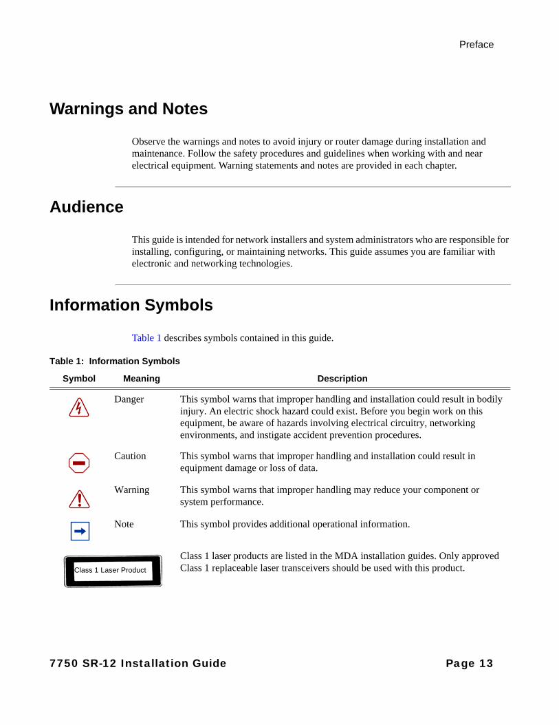
Table 1 describes symbols contained in this guide.
Table 1: Information Symbols
Symbol Meaning Description
Danger This symbol warns that improper handling and installation could result in bodily injury. An electric shock hazard could exist. Before you begin work on this equipment, be aware of hazards involving electrical circuitry, networking environments, and instigate accident prevention procedures.
Caution This symbol warns that improper handling and installation could result in equipment damage or loss of data.
Warning This symbol warns that improper handling may reduce your component or system performance.
Note This symbol provides additional operational information.
Class 1 laser products are listed in the MDA installation guides. Only approved Class 1 replaceable laser transceivers should be used with this product. Class 1 Laser Product
7750 SR-12 Installation Guide Page 13

Preface
Technical Support
If you purchased a service agreement for your 7750 SR-12 router and related products from a distributor or authorized reseller, contact the technical support staff for that distributor or reseller for assistance. If you purchased an Alcatel-Lucent service agreement, contact technical assistance at:
http://www.alcatel-lucent.com/wps/portal/support
Report documentation errors, omissions and comments to:
Include document name, version, part number and page(s) affected.
Page 14 7750 SR-12 Installation Guide
7750 SR-12 Overview
In This Chapter
This chapter introduces the Alcatel-Lucent 7750 SR-12 router and provides an overview of the following topics:
• Chassis Features on page 16
• 7750 SR-12 System Installation Process on page 36
7750 SR-12 Installation Guide Page 15
Chassis Features
Chassis Features
In the 7750 SR-12 chassis, the card slots are vertically oriented. IOM slots are numbered 1 through 10. You can install a maximum of two MDAs on each IOM. You can install MDAs in either MDA slot 1 (top slot) or MDA slot 2 (bottom slot).
You can install a maximum of two SF/CPMs in the center SF/CPM slots of your 7750 SR-12 chassis, designated as slots A and B. You must install at least one SF/CPM for the router to operate. The redundant SF/CPM operates in standby mode and takes over system operation if the primary SF/CPM fails.
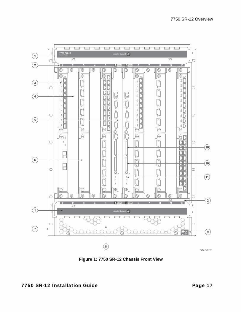
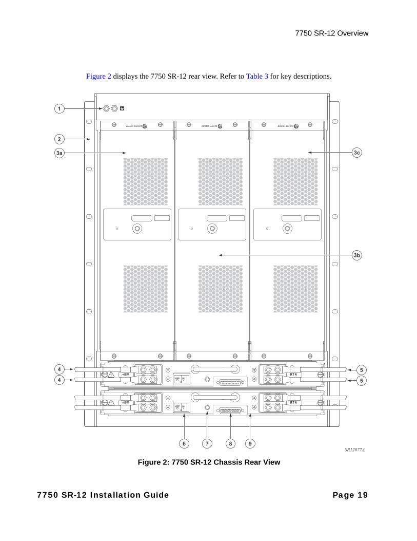
The 7750 SR-12 provides access to components from both the front and back sides. The filter tray, SF/CPMs, IOMs, MDAs, and IMMs are accessed from the front of the chassis. The power entry modules (PEMs) and cooling trays (impeller trays) are accessible from the chassis rear. Figure 1 and Figure 2 show the front and rear views, respectively.
DC PEMs are horizontally oriented and are accessed through the lower rear of the chassis. The top slot is number 1 and the bottom slot is number 2. You can connect DC PEMs directly to a DC power source (Figure 6). Alternatively, you can obtain power by using AC power rectifiers (Figure 7).
The mounting brackets for the chassis are factory installed to mount in a standard 19-inch wide rack. Refer to Table 2 for key descriptions of chassis features.
Page 16 7750 SR-12 Installation Guide
7750 SR-12 Overview
Figure 1: 7750 SR-12 Chassis Front View
3
1
2
8
4
5
1
6
7
11
10
10
2
9
SR12001C
7750 SR-12 Installation Guide Page 17
Chassis Features
Table 2: Chassis Front View Features
Key Description
1 Cable management system
2 Chassis slot numbers
3 MDA (installed)
4 Impedance panel
5 SF/CPM
6 MDA blank panel
7 Rack mounting brackets
8 Air vent
9 ESD plug
10 Compact flash slots
11 Compact flash slot 3 (cf3:)
Page 18 7750 SR-12 Installation Guide
7750 SR-12 Overview
Figure 2 displays the 7750 SR-12 rear view. Refer to Table 3 for key descriptions.
Figure 2: 7750 SR-12 Chassis Rear View
1
2
87 96
3a
4
4
3b
3c
5
5
SR12077A
7750 SR-12 Installation Guide Page 19
Chassis Features
Table 3: Chassis Rear View Features
Key Description
1 Grounding studs
2 Rack mounting brackets
3a Impeller (fan) tray #1
3b Impeller (fan) tray #2
3c Impeller (fan) tray #3
4 VDC studs for DC power cable
5 RTN studs for DC power cable
6 OFF/ON DC switch
7 PEM-3 LED
8 DB-25 connector (status)
9 DC PEM-3s. The top slot is referred to as PEM slot 1. The lower slot is referred to as PEM slot 2.
Page 20 7750 SR-12 Installation Guide
7750 SR-12 Overview
7750 SR-12 Modules
This section describes the 7750 SR-12 SF/CPM, IOMs, and MDAs.
• SF/CPMs on page 21
• Input/Output Modules (IOMs) on page 26
• Media Dependent Adapters (MDAs) on page 26
• Integrated Media Modules (IMMs) on page 27
SF/CPMs
The SF/CPM(s) control the routing and switching functions for the 7750 SR-12 system. The router operates with a minimum of one SF/CPM that you must install in either center slot A or B.
The SF/CPM connects directly to the backplane and carries traffic between line cards. The backplane provides high-speed access to the SF/CPMs, IOMs, and MDAs.
The switch fabric (SF) portion of the SF/CPM receives and directs traffic to the appropriate destinations according to the routing information.
Each SF/CPM module can accommodate up to three compact flash memory cards that can be used to copy and store system boot, software images, and configuration files and logs.
Note: There are three different versions of the SF/CPM module: SFM2, SFM3 and SFM4. SFM2 is referred to and labeled as SFM-400G for SR-12. But in fact it is capable of 500G switching capacity.Note: The SFM3 has improved processing capability with multi-core CPU and increased memory. The SR-12 uses the SFM3-12 with 500G switching capacity. Note: The SFM4 enables the SR systems to go to full duplex Terabit capacity (2 Terabit half duplex) to enable the platform to be fully populated with 100Gb/s linecards.
7750 SR-12 Installation Guide Page 21
Chassis Features
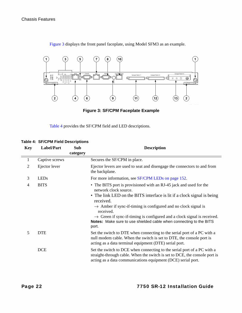
Figure 3 displays the front panel faceplate, using Model SFM3 as an example.
Figure 3: SF/CPM Faceplate Example
Table 4 provides the SF/CPM field and LED descriptions.
MDA0098
2 24
8 10
9 13
1 15 7
6 11 12
3
Table 4: SF/CPM Field Descriptions
Key Label/Part Subcategory
Description
1 Captive screws Secures the SF/CPM in place.
2 Ejector lever Ejector levers are used to seat and disengage the connectors to and from the backplane.
3 LEDs For more information, see SF/CPM LEDs on page 152.
4 BITS • The BITS port is provisioned with an RJ-45 jack and used for the network clock source.
• The link LED on the BITS interface is lit if a clock signal is being received. → Amber if sync-if-timing is configured and no clock signal is
received.→ Green if sync-if-timing is configured and a clock signal is received.
Notes: Make sure to use shielded cable when connecting to the BITS port.
5 DTE Set the switch to DTE when connecting to the serial port of a PC with a null modem cable. When the switch is set to DTE, the console port is acting as a data terminal equipment (DTE) serial port.
DCE Set the switch to DCE when connecting to the serial port of a PC with a straight-through cable. When the switch is set to DCE, the console port is acting as a data communications equipment (DCE) serial port.
Page 22 7750 SR-12 Installation Guide

7750 SR-12 Overview
6 Console The console port is provisioned with a DB-9 connector and used for initial system startup, system configuration, and monitoring. The console port, a Universal Asynchronous Receiver/Transmitter (UART) port, is used for system configuration and monitoring. Use an EIA/TIA-232 DCE console cable to connect a terminal to the console port.
7 AUX Reserved for future use.
8 Alarm The Alarm port is provisioned as a DB-9 serial port and is used to connect to external alarm devices that report conditions that trigger red or amber alarms.
9 ACO/LT The Audible Alarm Cutoff/Lamp Test (ACO/LT) button verifies the operability of LEDs. When you press this button, all LEDs on all chassis modules should temporarily illuminate and blink until the button is released. The ACO/LT button basically tests the functionality and operability of all LEDs on the chassis and components of the chassis. If any LEDs do not illuminate and blink, the LED might not be functioning properly.Exception: The following LEDs do not illuminate with a Lamp Test: the AUX LED on the CPM (Auxiliary is not supported, and the Laser ON/OFF and WAN LEDs on IMM/MDA).This button also turns off all external alarm relay control bits until the next new alarm condition.
10 Mgmt Link The Management port is a 10/100 Mb/s Ethernet port which is a channel to download images and manage the system. This port is provisioned with an RJ-45 connector. Use a CAT5 Ethernet cable to connect to the port.• Amber: 10 Mb/s• Green: 100 Mb/s• Unlit: Operationally down.Notes: Make sure to use shielded cable when connecting to the Management port.
Data • Green (blinking): RX/TX activity.• Amber (blinking): Error condition.
11 Compact Flash #1 (Slot) • Default filename: cf1:• See the Compact Flash LED description for the status of a compact
flash slot.• To eject a flash card, gently press the ejector button until the flash card
releases.
Table 4: SF/CPM Field Descriptions (Continued)
Key Label/Part Subcategory
Description
7750 SR-12 Installation Guide Page 23
Chassis Features
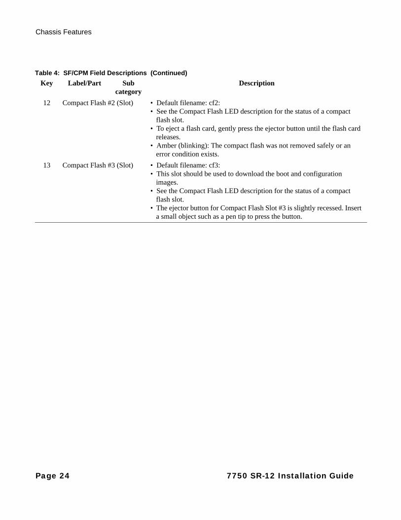
12 Compact Flash #2 (Slot) • Default filename: cf2:• See the Compact Flash LED description for the status of a compact
flash slot. • To eject a flash card, gently press the ejector button until the flash card
releases.• Amber (blinking): The compact flash was not removed safely or an
error condition exists.
13 Compact Flash #3 (Slot) • Default filename: cf3:• This slot should be used to download the boot and configuration
images.• See the Compact Flash LED description for the status of a compact
flash slot.• The ejector button for Compact Flash Slot #3 is slightly recessed. Insert
a small object such as a pen tip to press the button.
Table 4: SF/CPM Field Descriptions (Continued)
Key Label/Part Subcategory
Description
Page 24 7750 SR-12 Installation Guide
7750 SR-12 Overview
SYNCHRONIZATION IN REDUNDANT SYSTEMS
The 7750 SR-12 router is capable of a 1:1 control processor module (CPM) redundancy scheme. Redundancy methods facilitate system synchronization between the active and standby CPMs so they maintain identical operational parameters to prevent inconsistencies in the event of a CPM failure.
When automatic system synchronization is enabled for an entity, any save or delete file operation configured on the primary, secondary, or tertiary locations on the active CPM file system are mirrored in the standby CPM file system.
Although software configurations and images can be copied or downloaded from remote locations, synchronization can only occur locally between compact flash drives (cf1:, cf2:, and cf3:). Synchronization can occur either:
• Automatically — Automatic synchronization is disabled by default. To enable automatic synchronization, enter the config>redundancy>synchronize command with either the boot-env parameter or config parameter.
When you specify the boot-env parameter, the BOF, boot.ldr, config, and image files are automatically synchronized. When you specify the config parameter, only the config files are automatically synchronized.
Automatic synchronization also occurs whenever the BOF is modified and when you enter an admin>save command with no filename specified.
• Manually — To execute synchronization manually, enter the admin>redundancy>synchronize command with the boot-env parameter or the config parameter.
When you specify the boot-env parameter, the BOF, boot.ldr, config, and image files are synchronized. When you specify the config parameter, only the config files are synchronized.
For more information about redundancy and synchronization, refer to the Alcatel OS System Guide.
SYNCHRONIZING REDUNDANT BITS TIMING PORTS
In 7750 SR-12 systems with redundant SF/CPMs, a Y-cable can be connected to the Building Integrated Timing Supply (BITS) port on each CPM front panel.
7750 SR-12 Installation Guide Page 25
Chassis Features
Input/Output Modules (IOMs)
7750 SR-12 routers support a wide variety of interfaces, including Ethernet, SONET/SDH (channelized and concatenated), and ATM. Each IOM features a single-slot baseboard that can carry up to two hot-swappable MDAs with Small Form-factor Pluggable (SFP) optics, providing flexibility to mix-and-match interfaces per-slot as customer and network needs dictate.
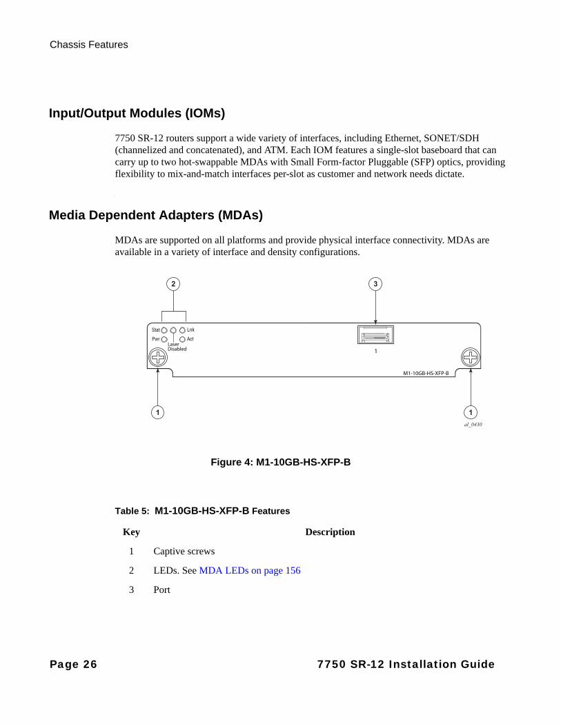
Media Dependent Adapters (MDAs)
MDAs are supported on all platforms and provide physical interface connectivity. MDAs are available in a variety of interface and density configurations.
Figure 4: M1-10GB-HS-XFP-B
al_0430
2 3
11
Table 5: M1-10GB-HS-XFP-B Features
Key Description
1 Captive screws
2 LEDs. See MDA LEDs on page 156
3 Port
Page 26 7750 SR-12 Installation Guide
7750 SR-12 Overview
Integrated Media Modules (IMMs)
The 7750 SR Integrated Media Modules (IMMs) provide high density and high throughput in a single Ethernet line card that combines a fully distributed forwarding and packet processing services engine with physical Ethernet ports. The 7750 SR IMM delivers comprehensive IEEE 802.3 compliance and supports a broad range of copper and pluggable optical interfaces, enabling you to use many fast Ethernet, gigabit Ethernet and 10 gigabit Ethernet applications. For more information, refer to the IMM Installation Guide.
7750 SR-12 Installation Guide Page 27

Chassis Features
Chassis Components
The 7750 SR-12 chassis components are described in the following sections:
• Power Supplies on page 28
→ DC Power Entry Modules on page 29
→ AC to DC Rectifiers on page 31
• Cooling System on page 33
• Air Filter on page 34
• Impedance Panels on page 34
Power Supplies
Two slots in the chassis are designated for hot swappable, load-sharing, DC power entry modules (PEMs). There are two DC PEM types: 100-Amp single-feed PEMs and 175-Amp dual-feed PEM-3s. For more information on PEMs, see Installing DC Power Entry Modules (PEMs) on page 88.
AC power can be converted to DC power using external AC to DC rectifiers available from Alcatel-Lucent. For more information on configuring your system to use AC power, see Installing an AC Power Shelf on page 113.
POWER REDUNDANCY
You must install at least one DC PEM or PEM-3 in the 7750 SR-12 chassis. You can install an additional PEM or PEM-3 for power redundancy.
If you need to convert AC power to usable DC power and you are using 100-Amp single-feed PEMs, you can install up to two rectifiers in the same AC power shelf that you connect to your PEM. If you need to convert AC power to usable DC power and you are using 175-Amp dual-feed PEM-3s, you install four rectifiers in the AC power shelf that you connect to your PEM-3. For redundant operation, you can install a second AC power shelf. Connect the second power shelf to the second PEM or PEM-3. This ensures that the second DC PEM has an independent redundant power source.
Note: DC PEM-3s are required if you have IOM3-XPs, IOM3-XP-Bs or IMMs installed in your system.
Page 28 7750 SR-12 Installation Guide

7750 SR-12 Overview
DC POWER ENTRY MODULES
You can install and remove DC PEMs from the rear of the 7750 SR-12 chassis power slots 1 and 2. One PEM can support the full system electrical current requirements if you are operating the 7750 SR-12 without power redundancy. You must install two PEMs for redundancy. These PEMs must be powered on at all times. There are two types of PEMs: the 175-Amp PEM-3 and the 100-Amp PEM. The PEM-3 is required for the 7750 SR-12 chassis when the router has one or more IOM3-XPs, IOM3-XP-Bs, or IMMs installed. Due to increased power requirements, a 175 AMP DC PEM-3 provides dual feeds.
Figure 5 displays the 175 AMP DC PEM-3. Figure 6 displays the 100-Amp DC PEM. Table 6 provides the component descriptions for both the PEM and PEM-3.
Always operate an energized chassis with the safety cover installed over the DC power terminal block to prevent contact with hazardous voltages and currents and to prevent accidental removal.
Power cables are not included. You must order or supply power cables compliant with your local safety codes. For information about preparing cables, refer to Preparing DC-Input Power Wiring for the 100-Amp DC PEM on page 102.
There are no field replaceable parts on a DC PEM. Replace the entire unit in the event of a failure.
Figure 5: 175-Amp DC PEM-3
2
1
1
3
5
SR12061A
2
4
7750 SR-12 Installation Guide Page 29
Chassis Features
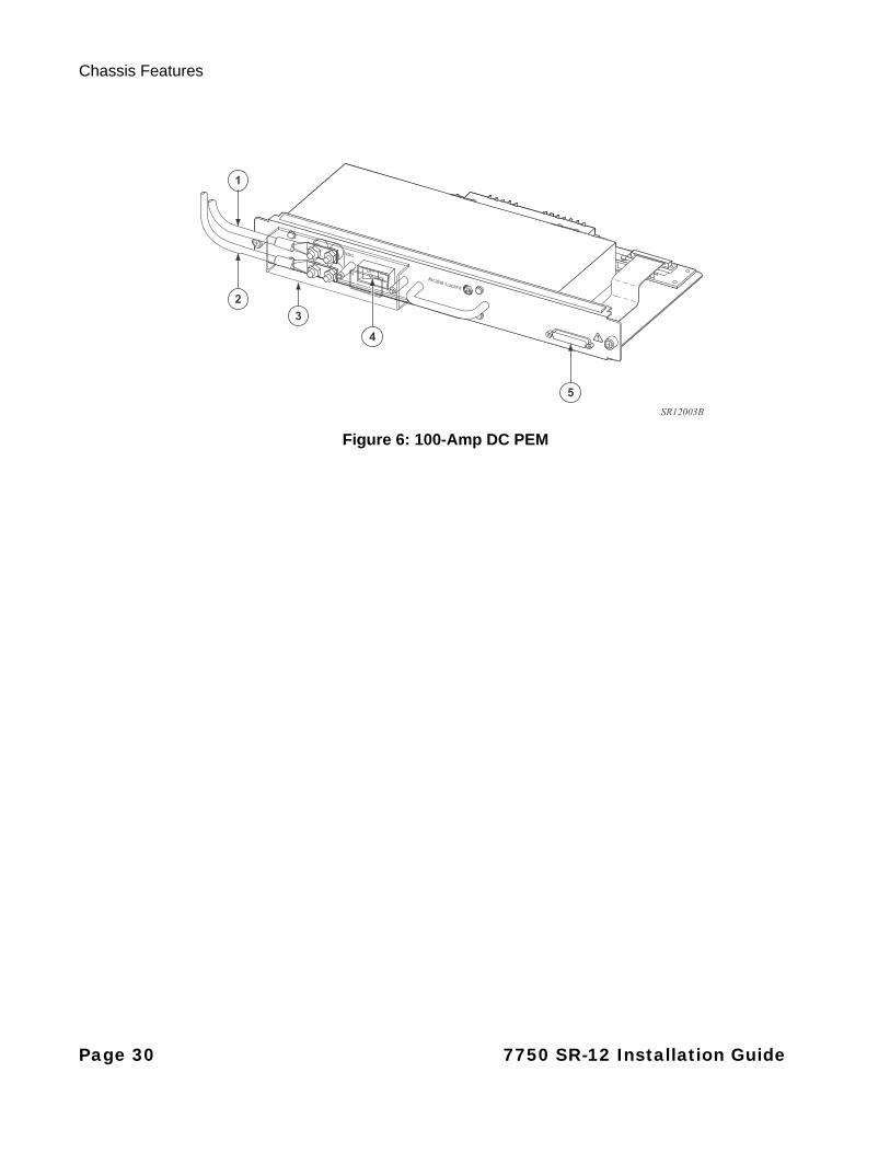
Figure 6: 100-Amp DC PEM
5
1
2
3
4
SR12003B
Page 30 7750 SR-12 Installation Guide
7750 SR-12 Overview
AC TO DC RECTIFIERS
AC to DC rectifiers change 200/240V AC power to -48 VDC power. See Figure 7 for an illustration of an AC to DC rectifier and Table 7 for descriptions of the callouts on the illustration.
Each power shelf can accommodate up to four 2500W AC to DC rectifiers that plug into a common power backplane in the AC-input power shelf. You must connect each AC power shelf to a separate PEM installed in the 7750 SR-12 chassis. For redundancy, you must install two PEMs, each connected to a separate AC to DC rectifier shelf. You must install four rectifiers in each shelf.
The AC to DC rectifiers in each power shelf provide automatic load-sharing. When a rectifier is removed, the remaining rectifiers adjust to fulfill the power requirements and maintain uninterrupted system power.
The rectifiers in the AC power shelf are hot-swappable. You can remove or replace a power module while the system is operating without affecting system operation. For maximum redundancy, connect each AC-input power module to a separate AC power source. The power source (outlet) should be located near the equipment rack and be easily accessible.
The power cord serves as a disconnect device for each rectifier. To remove power to an individual rectifier, the unit must be disconnected from the connectors.
Table 6: DC Power Entry Module Features
Key Description
1 Power cable (VDC)
2 Return cable (RTN)
3 Safety cover
4 I / O (on/off) switch (accessible without removing the safety cover)
5 DB-25 connector (provides status if you are using AC power)
Note: If you are using 100-Amp PEMs, your rectifier shelf will be split so that each PEM is connected to one half of the shelf. If you are using 175-Amp PEM-3s, each PEM-3 connects to a separate rectifier shelf.
7750 SR-12 Installation Guide Page 31
Chassis Features
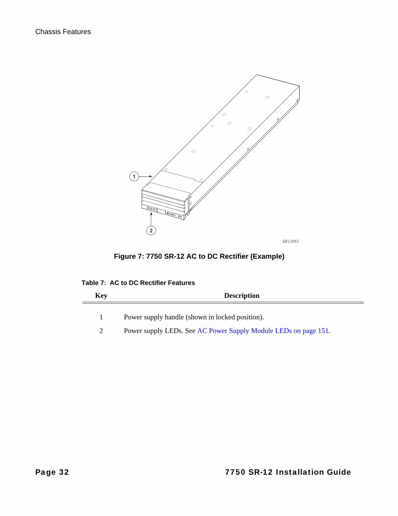
Figure 7: 7750 SR-12 AC to DC Rectifier (Example)
1
2
SR12065
Table 7: AC to DC Rectifier Features
Key Description
1 Power supply handle (shown in locked position).
2 Power supply LEDs. See AC Power Supply Module LEDs on page 151.
Page 32 7750 SR-12 Installation Guide
7750 SR-12 Overview
Cooling System
The 7750 SR-12 system is cooled by hot-swappable impeller (fan) trays. All three impeller trays must always be installed and fully operational while the 7750 SR-12 is powered up. The trays are accessed from the rear of the chassis and are interchangeable in any tray slot.
The impellers pull air through the system from front-filtered intake vents, across the IOMs and SF/CPMs, and exhausts the air through rear vents. The impellers spin at high speed during system initialization and then slow down to normal operating speed when system initialization is complete.
The 7750 SR-12 cooling system supports two types of impeller fan trays: the Standard Fan Tray and the Enhanced Fan Tray. The 7750 SR-12 Enhanced Fan Tray offers the following improved capabilities:
• Increased air flow rate from 350 to 1000 cubic feet per minute (CFM).
• Increased level of granularity for fan speed (up to 20 speed settings) when used in conjunction with an SFM3 and software release 8.0R4 and later.
• Improved acoustical performance (69.8 dBA at 350 CFM).
• Reduced power consumption.
The 7750 SR-12 cooling system consists of the following components:
• Either (3) Standard Fan Trays or (3) Enhanced Fan Trays, each with two impellers.
• One air filter.
There are three fan tray slots in the rear of the 7750 SR-12 chassis. The left slot is designated as fan tray #1, the middle slot is designated as fan tray #2, and the right slot is designated as fan tray #3.
Note: When the chassis uses the 100 Gbps IMM, Enhanced Fan Trays are required.
Note: There are three temperature sensors per IOM and SF/CPM and one temperature sensor per MDA. The highest temperature from any sensor is reported as the temperature for that slot. With either the Standard or Enhanced Fan Tray, if the CPM LED is lit amber (indicating a fan problem), use the show card 1 detail CLI command to monitor the current temperature and temperature threshold fields. Also, on an Enhanced Fan Tray, if the fan tray front panel LED is lit red, use the show card 1 detail CLI command to monitor the current temperature and temperature threshold fields. If the temperature rises quickly and remains above the temperature threshold, an alarm is generated. Repair or replace the unit immediately if a failure occurs.
7750 SR-12 Installation Guide Page 33
Chassis Features
The cooling system components work together to keep the internal components within the acceptable temperature range.
For the Standard Impeller Fan Tray, the status indicator LEDs are displayed on the active CPM front panel, labeled Fan Status. A green LED indicates normal operation. The LED is amber if there is an impeller failure or unlit if there is no power to a tray or a tray is not installed in the slot.
For the Enhanced Impeller Fan Tray, there are two sets of status indicators. One set is located on the active CPM front panel. A green LED indicates normal operation. The LED is amber if there is an impeller failure. It is blinking if a fan tray is not installed in the slot or if the fan temperature is too high.
The second set is located on the fan tray front panel. A green LED indicated normal operation. The LED is amber when it is safe to remove the enhanced fan tray from the chassis. The LED is red when the fan tray is starting up or to indicate a fault in the fan tray. If the LED is unlit there is no power to the fan tray.
The 7750 SR-12 chassis is shipped with three factory-installed impeller trays. You must replace the entire tray if an impeller fails.
Air Filter
The air filter prevents large particles, debris, and dust from entering and circulating through the system. Filters should be inspected monthly and replaced when indications of accumulated dust are present.The filter is factory installed and field replaceable.
Impedance Panels
Impedance panels are required in all empty card and component slots to prevent excess dust accumulation and to help control airflow and electromagnetic interference, and for safety reasons. Impedance panels include a blank board that enhances airflow and cooling. Impedance panels do not have board components or connector pins.
Cable Management System
The 7750 SR-12 chassis can accommodate two cable management trays. The trays are mounted on the front of the chassis, above and below the card slots. The cable management system manages fiber optic cables so they do not interfere with the insertion or removal of IOMs and MDAs and prevents sharp bends that can damage cable or degrade performance.
Page 34 7750 SR-12 Installation Guide
7750 SR-12 Overview
Component Operating Requirements
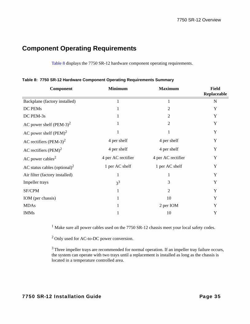
Table 8 displays the 7750 SR-12 hardware component operating requirements.
1 Make sure all power cables used on the 7750 SR-12 chassis meet your local safety codes.
2 Only used for AC-to-DC power conversion.
3 Three impeller trays are recommended for normal operation. If an impeller tray failure occurs, the system can operate with two trays until a replacement is installed as long as the chassis is located in a temperature controlled area.
Table 8: 7750 SR-12 Hardware Component Operating Requirements Summary
Component Minimum Maximum FieldReplaceable
Backplane (factory installed) 1 1 N
DC PEMs 1 2 Y
DC PEM-3s 1 2 Y
AC power shelf (PEM-3)2 1 2 Y
AC power shelf (PEM)2 1 1 Y
AC rectifiers (PEM-3)2 4 per shelf 4 per shelf Y
AC rectifiers (PEM)2 4 per shelf 4 per shelf Y
AC power cables2 4 per AC rectifier 4 per AC rectifier Y
AC status cables (optional)2 1 per AC shelf 1 per AC shelf Y
Air filter (factory installed) 1 1 Y
Impeller trays 33 3 Y
SF/CPM 1 2 Y
IOM (per chassis) 1 10 Y
MDAs 1 2 per IOM Y
IMMs 1 10 Y
7750 SR-12 Installation Guide Page 35
7750 SR-12 System Installation Process
7750 SR-12 System Installation Process
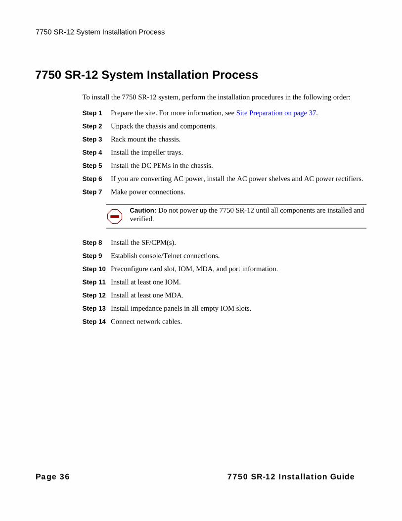
To install the 7750 SR-12 system, perform the installation procedures in the following order:
Step 1 Prepare the site. For more information, see Site Preparation on page 37.
Step 2 Unpack the chassis and components.
Step 3 Rack mount the chassis.
Step 4 Install the impeller trays.
Step 5 Install the DC PEMs in the chassis.
Step 6 If you are converting AC power, install the AC power shelves and AC power rectifiers.
Step 7 Make power connections.
Step 8 Install the SF/CPM(s).
Step 9 Establish console/Telnet connections.
Step 10 Preconfigure card slot, IOM, MDA, and port information.
Step 11 Install at least one IOM.
Step 12 Install at least one MDA.
Step 13 Install impedance panels in all empty IOM slots.
Step 14 Connect network cables.
Caution: Do not power up the 7750 SR-12 until all components are installed and verified.
Page 36 7750 SR-12 Installation Guide
Site Preparation
In This Chapter
This chapter provides information about preparing your site to install a 7750 SR-12 router.
This chapter provides an overview of the following topics:
• Warnings and Notes on page 38
• System Specifications on page 40
→ Chassis Specifications on page 40
→ Environmental Specifications on page 40
→ Power Module Specifications on page 41
→ PEM Electrical Characteristics on page 42
→ Impeller Fan Tray Specifications on page 43
→ MDA and MDA-XP Specifications on page 44
→ Calculating Maximum Power Consumption on page 45
→ Component Specifications on page 54
→ The Equipment Rack on page 56
• Safety Considerations on page 58
• Safety Standards/Compliance Agency Certifications on page 61
7750 SR-12 Installation Guide Page 37
Warnings and Notes
Warnings and Notes
Warning:
• Do not assume that power has been disconnected from a circuit. Be sure to disconnect power to the equipment rack and external cables before installing or removing the 7750 SR-12 router.
• Do not install equipment that appears to be damaged.
• Install this unit in a restricted area that is only accessible by authorized service personnel.
• Do not stack any other equipment on top of the router. The chassis is not designed to support weight on top of it.
Page 38 7750 SR-12 Installation Guide
Site Preparation
Notes:
• Prepare the equipment rack and site before installing the router. Plan the router placement near the power sources and network interface connections.
• Remove paint and other nonconductive coatings from surfaces between the mounting hardware and the rack. Clean surfaces with an anti-oxidant before you install your router in the rack. The path between the chassis and the rack must be of sufficiently low impedance to facilitate the operation of any circuit overcurrent protection and it must be capable of safely conducting any fault current likely to be imposed.
• The 7750 SR-12 chassis is suitable for connection to a CBN or IBN grounding system.
• The 7750 SR-12 is intended to be located in a Central Office.
• An empty 7750 SR-12 chassis weighs approximately 124 lbs. (56.37 kg).
• Use a hand cart or mechanical lift to lift or move the router.
• Always install the heaviest equipment on the bottom of the rack to keep the center of gravity of the equipment rack as low as possible.
• To provide necessary stability, ensure that the equipment rack is bolted to the floor. Ceiling brackets are useful to provide additional stability.
• The equipment rack must be properly grounded.
• Install components after the chassis is installed in the rack.
• Maintain a clearance of at least 20 inches (50.8 cm) at the front and back of the router to ensure adequate room for component installation and service.
• Maintain a clearance of at least three inches (7.6 cm) on each side to ensure adequate air intake and exhaust.
• Maintain adequate air flow to and from all equipment in the rack, ensuring that nothing impedes with intake or exhaust air flow.
• The 7750 SR-12 router includes factory-installed rack-mounting brackets to install in a 19-inch equipment rack.
• If you have one or more IMMs installed in your router, you must install impedance panels in any slots that do not contain an IOM or IMM.
• If you have one or more IMMs installed in your router, you must use PEM-3s.
• If you are installing the 12-Port 10GB-SFP+ (IMM12-10GB-SFP+) and/or the 1-Port 100GB-CFP (IMM1-100GB-CFP), you must install Enhanced Fan Trays in your router
7750 SR-12 Installation Guide Page 39

System Specifications
System Specifications
Chassis Specifications
Environmental Specifications
Table 9: Chassis Specifications
Parameter Description
Dimensions Without cable management unitWith cable management unit
24.5 in. H x 17.5 in. W x 25.4 in. D24.5 in. H x 17.5 in. W x 30.1 in. D
Chassis weight (empty) 124 lbs. (56.37 kg)
Chassis weight (loaded) 342.5 lbs. (155.4 kg) (approximately)
Mounting Mount in 19-inch equipment rack. Bracket ears are factory installed to front-mount the chassis in a 19-inch rack.
Note: The Enhanced Fan Tray is 2.7 in. deeper than the standard fan tray, while the Reduced-Depth Enhanced Fan Tray is 1.55 in. deeper than the standard fan tray. When upgrading systems installed in cabinets with rear doors, be aware of the added depth to ensure proper clearance.
Table 10: Environmental Specifications
Parameter Description
Operating:
Temperature 5 to 40°C (41 to 104°F)
Short term -5 to 55º C (23 to 131º F)
Maximum altitude 60 m (197 ft.) below sea level and 1800 m (6000 ft.) above sea level at 40°C and between 1800m (6000 ft) and 4000 m (13,000 ft.) above sea level, at 30°C.
Relative humidity 5 to 85% (non-condensing)
Short term 5 to 90% (non-condensing)
Page 40 7750 SR-12 Installation Guide
Site Preparation
Power Module Specifications
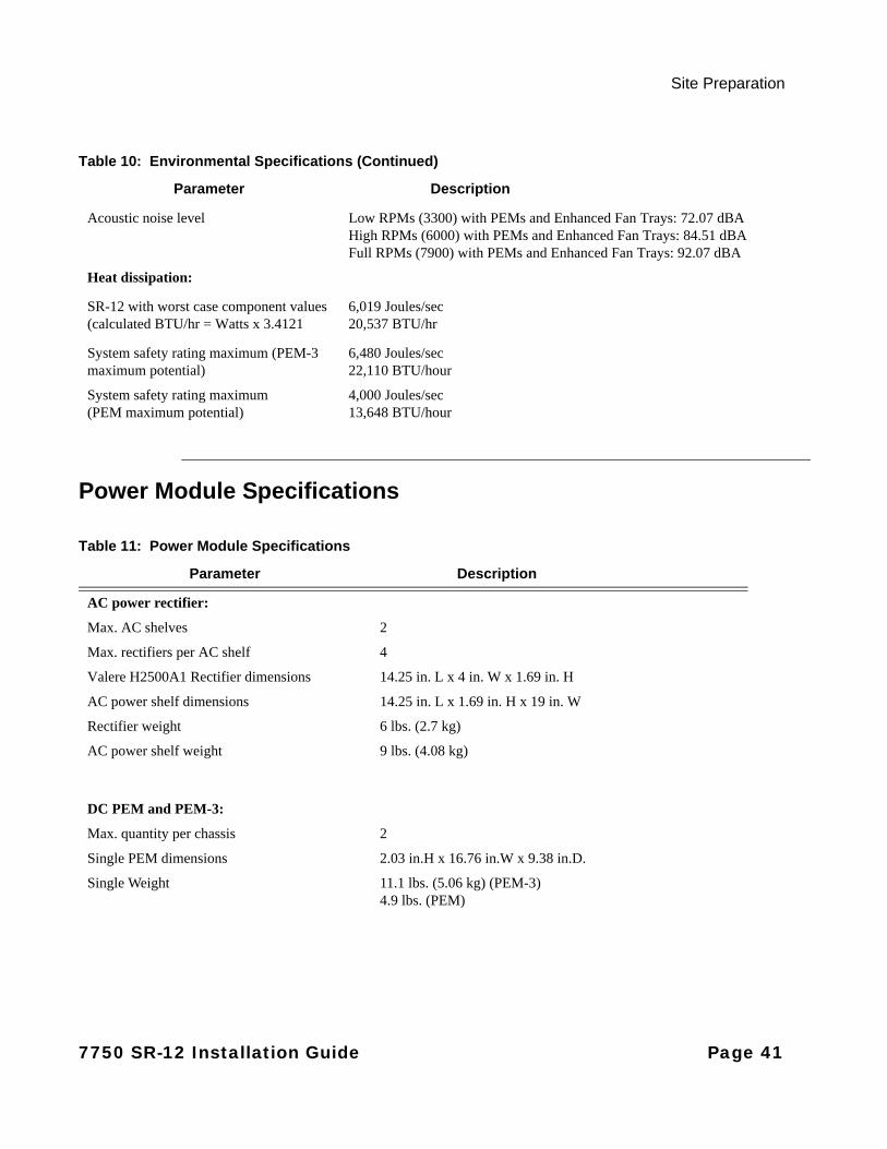
Acoustic noise level Low RPMs (3300) with PEMs and Enhanced Fan Trays: 72.07 dBA High RPMs (6000) with PEMs and Enhanced Fan Trays: 84.51 dBA Full RPMs (7900) with PEMs and Enhanced Fan Trays: 92.07 dBA
Heat dissipation:
SR-12 with worst case component values (calculated BTU/hr = Watts x 3.4121
6,019 Joules/sec20,537 BTU/hr
System safety rating maximum (PEM-3 maximum potential)
6,480 Joules/sec22,110 BTU/hour
System safety rating maximum (PEM maximum potential)
4,000 Joules/sec13,648 BTU/hour
Table 11: Power Module Specifications
Parameter Description
AC power rectifier:
Max. AC shelves 2
Max. rectifiers per AC shelf 4
Valere H2500A1 Rectifier dimensions 14.25 in. L x 4 in. W x 1.69 in. H
AC power shelf dimensions 14.25 in. L x 1.69 in. H x 19 in. W
Rectifier weight 6 lbs. (2.7 kg)
AC power shelf weight 9 lbs. (4.08 kg)
DC PEM and PEM-3:
Max. quantity per chassis 2
Single PEM dimensions 2.03 in.H x 16.76 in.W x 9.38 in.D.
Single Weight 11.1 lbs. (5.06 kg) (PEM-3)4.9 lbs. (PEM)
Table 10: Environmental Specifications (Continued)
Parameter Description
7750 SR-12 Installation Guide Page 41
System Specifications
PEM Electrical Characteristics
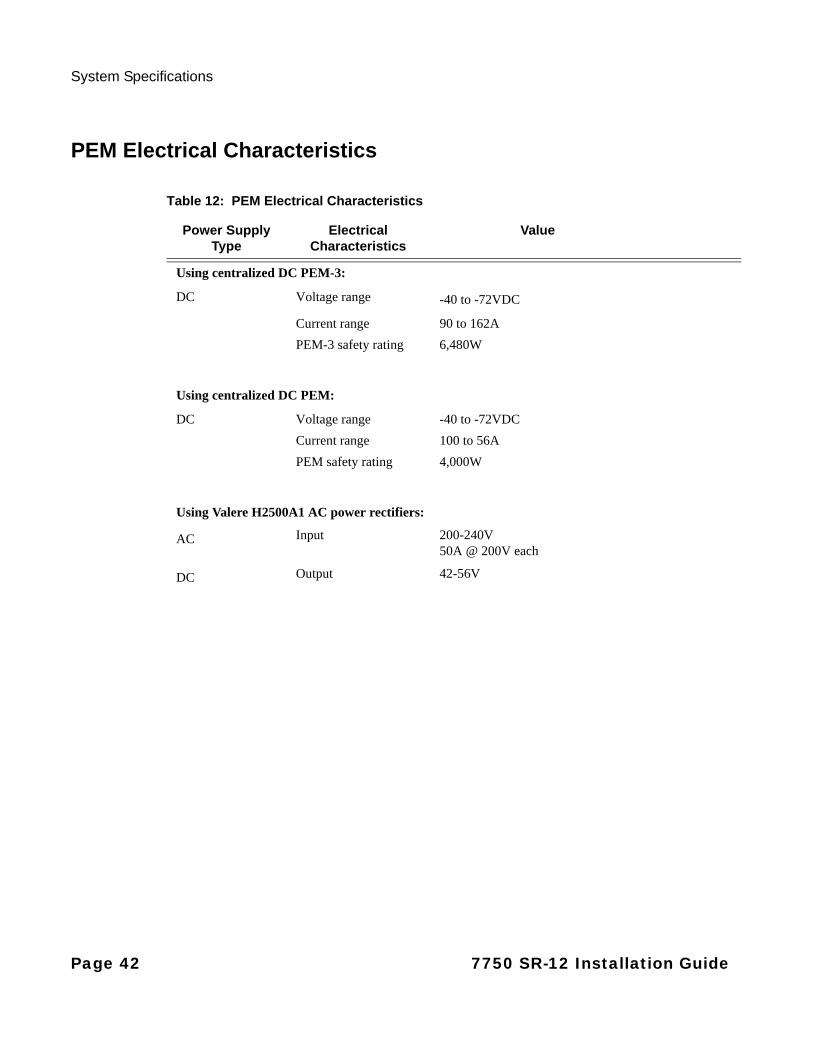
Table 12: PEM Electrical Characteristics
Power Supply Type
Electrical Characteristics
Value
Using centralized DC PEM-3:
DC Voltage range -40 to -72VDC
Current range 90 to 162A
PEM-3 safety rating 6,480W
Using centralized DC PEM:
DC Voltage range -40 to -72VDC
Current range 100 to 56A
PEM safety rating 4,000W
Using Valere H2500A1 AC power rectifiers:
AC Input 200-240V50A @ 200V each
DC Output 42-56V
Page 42 7750 SR-12 Installation Guide
Site Preparation
Impeller Fan Tray Specifications
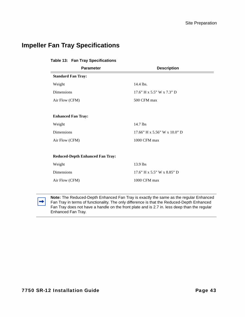
Table 13: Fan Tray Specifications
Parameter Description
Standard Fan Tray:
Weight 14.4 lbs.
Dimensions 17.6” H x 5.5” W x 7.3” D
Air Flow (CFM) 500 CFM max
Enhanced Fan Tray:
Weight 14.7 lbs
Dimensions 17.66” H x 5.56” W x 10.0” D
Air Flow (CFM) 1000 CFM max
Reduced-Depth Enhanced Fan Tray:
Weight 13.9 lbs
Dimensions 17.6” H x 5.5” W x 8.85” D
Air Flow (CFM) 1000 CFM max
Note: The Reduced-Depth Enhanced Fan Tray is exactly the same as the regular Enhanced Fan Tray in terms of functionality. The only difference is that the Reduced-Depth Enhanced Fan Tray does not have a handle on the front plate and is 2.7 in. less deep than the regular Enhanced Fan Tray.
7750 SR-12 Installation Guide Page 43

System Specifications
MDA and MDA-XP Specifications
Table 14: MDA and MDA-XP Specifications
Parameter Description
Dimensions 1.4 in. H x 7.5 in. W x 7 in. D
Weight Maximum of 2.5 lb.
Page 44 7750 SR-12 Installation Guide

Site Preparation
Calculating Maximum Power Consumption
The power consumption levels provided in Table 15 through 17 are provided for planning purposes only and do not represent actual power consumption. Your actual power consumption should always be lower than the figures shown in the tables.
The 7750 SR-12 routers have a voltage range of -40v to -72v. The lower your voltage the higher the current. This is an important factor for planning and calculating your maximum power consumption.
To calculate your maximum power consumption figure add up the wattage for each of the components installed in your system. This includes the chassis, IOMs, IMMs, SFMs, and MDAs in your system. Take the total wattage and divide by the lowest voltage threshold for your CO/POP. The result is your maximum current (amperage). See Table 23 for an example of the maximum power consumption of a system.
See Table 15 for chassis power consumption, Table 16 for MDA power consumption, and Table 17for board power consumption information.
Power consumption values are based on specific conditions, such as line rate of traffic and operating temperature of the modules. The following module conditions are used for power ratings:
• idle—Power consumption before the slot is configured or provisioned
• zero rate—0% line rate, at 25°C
• typical—50% line rate, at 25°C
• worst case—100% line rate, at 55°C
Table 15: Chassis Power Consumption
Component Chassis Configuration Watts
SR-12 Chassis (low RPMs) With PEMs and Standard Fan Trays 144 worst case
SR-12 Chassis (high RPMs) With PEMs and Standard Fan Trays 380 worst case
SR-12 Chassis (low RPMs) With PEMs and Enhanced Fan Trays 75 worst case
SR-12 Chassis (high RPMs) With PEMs and Enhanced Fan Trays 340 worst case
SR-12 Chassis (full RPMs) With PEMs and Enhanced Fan Trays 1185 worst case
SR-12 Chassis Without PEMs or Fan Trays 25 worst case
7750 SR-12 Installation Guide Page 45
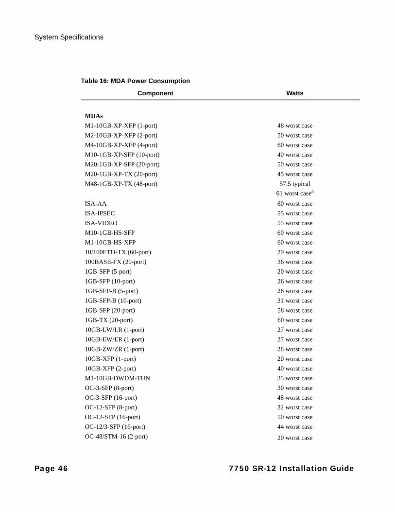
System Specifications
Table 16: MDA Power Consumption
Component Watts
MDAs
M1-10GB-XP-XFP (1-port) 48 worst case
M2-10GB-XP-XFP (2-port) 50 worst case
M4-10GB-XP-XFP (4-port) 60 worst case
M10-1GB-XP-SFP (10-port) 40 worst case
M20-1GB-XP-SFP (20-port) 50 worst case
M20-1GB-XP-TX (20-port) 45 worst case
M48-1GB-XP-TX (48-port) 57.5 typical
61 worst casea
ISA-AA 60 worst case
ISA-IPSEC 55 worst case
ISA-VIDEO 55 worst case
M10-1GB-HS-SFP 60 worst case
M1-10GB-HS-XFP 60 worst case
10/100ETH-TX (60-port) 29 worst case
100BASE-FX (20-port) 36 worst case
1GB-SFP (5-port) 20 worst case
1GB-SFP (10-port) 26 worst case
1GB-SFP-B (5-port) 26 worst case
1GB-SFP-B (10-port) 31 worst case
1GB-SFP (20-port) 58 worst case
1GB-TX (20-port) 60 worst case
10GB-LW/LR (1-port) 27 worst case
10GB-EW/ER (1-port) 27 worst case
10GB-ZW/ZR (1-port) 28 worst case
10GB-XFP (1-port) 20 worst case
10GB-XFP (2-port) 40 worst case
M1-10GB-DWDM-TUN 35 worst case
OC-3-SFP (8-port) 30 worst case
OC-3-SFP (16-port) 48 worst case
OC-12-SFP (8-port) 32 worst case
OC-12-SFP (16-port) 50 worst case
OC-12/3-SFP (16-port) 44 worst case
OC-48/STM-16 (2-port) 20 worst case
Page 46 7750 SR-12 Installation Guide
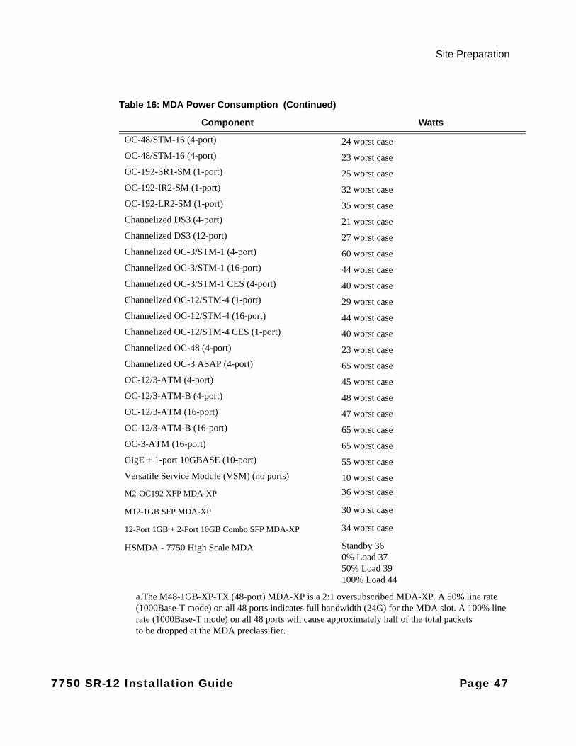
Site Preparation
OC-48/STM-16 (4-port) 24 worst case
OC-48/STM-16 (4-port) 23 worst case
OC-192-SR1-SM (1-port) 25 worst case
OC-192-IR2-SM (1-port) 32 worst case
OC-192-LR2-SM (1-port) 35 worst case
Channelized DS3 (4-port) 21 worst case
Channelized DS3 (12-port) 27 worst case
Channelized OC-3/STM-1 (4-port) 60 worst case
Channelized OC-3/STM-1 (16-port) 44 worst case
Channelized OC-3/STM-1 CES (4-port) 40 worst case
Channelized OC-12/STM-4 (1-port) 29 worst case
Channelized OC-12/STM-4 (16-port) 44 worst case
Channelized OC-12/STM-4 CES (1-port) 40 worst case
Channelized OC-48 (4-port) 23 worst case
Channelized OC-3 ASAP (4-port) 65 worst case
OC-12/3-ATM (4-port) 45 worst case
OC-12/3-ATM-B (4-port) 48 worst case
OC-12/3-ATM (16-port) 47 worst case
OC-12/3-ATM-B (16-port) 65 worst case
OC-3-ATM (16-port) 65 worst case
GigE + 1-port 10GBASE (10-port) 55 worst case
Versatile Service Module (VSM) (no ports) 10 worst case
M2-OC192 XFP MDA-XP 36 worst case
M12-1GB SFP MDA-XP 30 worst case
12-Port 1GB + 2-Port 10GB Combo SFP MDA-XP 34 worst case
HSMDA - 7750 High Scale MDA Standby 360% Load 3750% Load 39100% Load 44
a.The M48-1GB-XP-TX (48-port) MDA-XP is a 2:1 oversubscribed MDA-XP. A 50% line rate(1000Base-T mode) on all 48 ports indicates full bandwidth (24G) for the MDA slot. A 100% linerate (1000Base-T mode) on all 48 ports will cause approximately half of the total packetsto be dropped at the MDA preclassifier.
Table 16: MDA Power Consumption (Continued)
Component Watts
7750 SR-12 Installation Guide Page 47

System Specifications
The IMM power consumption values that follow are not in any way complete and comprehensive lists. New consumption values are added to this guide as they become available. Please check back to later releases of this guide for new power values and conditions.
The IMM power consumption values provided do not include any optic component power consumptions. The power ratings for optic components are listed in Table 20, “Optics Power Consumption,” on page 50.
Table 17: Board Power Consumption
Component Board Watts
IOM iom-20g 168 worst case
iom-20g-b 168 worst case
IOM2 iom2-20g 200 worst case
IOM3-XP iom3-xp 170 idle 200 zero rate230 typical275 worst case
IOM3-XP-B iom3-xp-ba
a.Requires implementation of Enhanced Fan Trays in the chassis
170 idle 200 zero rate230 typical275 worst case
IOM3-XP-C iom3-xp-ca 170 idle 200 zero rate230 typical275 worst case
SFM sfm-12 150 worst case
SFM2 sfm2-12 150 worst case
SFM3-12 sfm3-12 172 worst case
SFM4-12 sfm4-12 375 worst case
Table 18: IMM Power Consumption
Component Watts
IMMs:
48-Port 1GB SFP (IMM48-1GB-SFP) 375 worst case
48-Port 1GB SFP Multicorea
(IMM48-1GB-SFP-B)
100 idle256 zero rate345 typical375 worst case
Page 48 7750 SR-12 Installation Guide
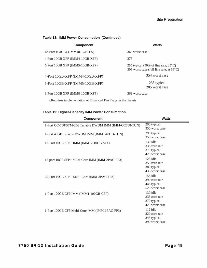
Site Preparation
48-Port 1GB TX (IMM48-1GB-TX) 365 worst case
4-Port 10GB XFP (IMM4-10GB-XFP) 375
5-Port 10GB XFP (IMM5-10GB-XFP) 255 typical (50% of line rate, 25°C)305 worst case (full line rate, at 55°C)
4-Port 10GB-XFP (IMM4-10GB-XFP) 354 worst case
5-Port 10GB-XFP (IMM5-10GB-XFP) 235 typical285 worst case
8-Port 10GB XFP (IMM8-10GB-XFP) 363 worst case
a.Requires implementation of Enhanced Fan Trays in the chassis
Table 19: Higher-Capacity IMM Power Consumption
Component Watts
1-Port OC-768/STM-256 Tunable DWDM IMM (IMM-OC768-TUN) 290 typical350 worst case
1-Port 40GE Tunable DWDM IMM (IMM1-40GB-TUN) 290 typical350 worst case
12-Port 10GE SFP+ IMM (IMM12-10GB-SF+) 130 idle335 zero rate370 typical425 worst case
12-port 10GE SFP+ Multi-Core IMM (IMM-2PAC-FP3) 125 idle 355 zero rate 380 typical 435 worst case
20-Port 10GE SFP+ Multi-Core (IMM-2PAC-FP3) 158 idle390 zero rate445 typical525 worst case
1-Port 100GE CFP IMM (IMM1-100GB-CFP) 130 idle335 zero rate370 typical425 worst case
1-Port 100GE CFP Multi-Core IMM (IMM-1PAC-FP3) 112 idle320 zero rate345 typical390 worst case
Table 18: IMM Power Consumption (Continued)
Component Watts
7750 SR-12 Installation Guide Page 49
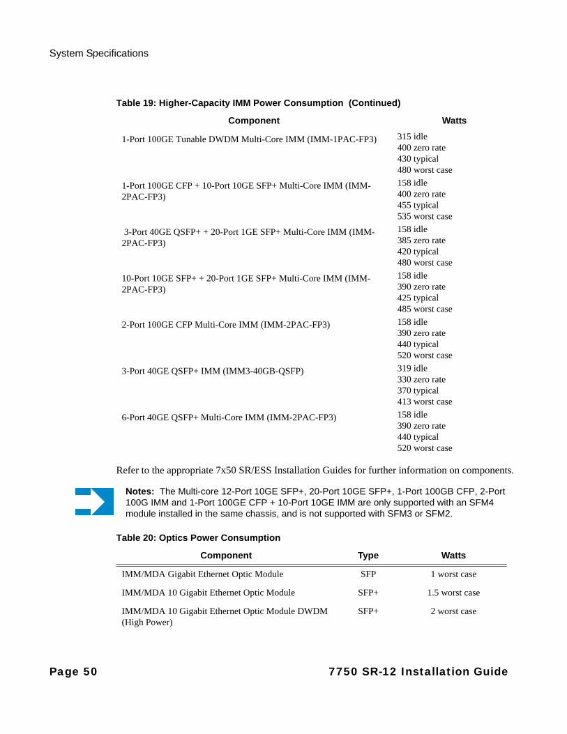
System Specifications
Refer to the appropriate 7x50 SR/ESS Installation Guides for further information on components.
1-Port 100GE Tunable DWDM Multi-Core IMM (IMM-1PAC-FP3) 315 idle400 zero rate430 typical480 worst case
1-Port 100GE CFP + 10-Port 10GE SFP+ Multi-Core IMM (IMM-2PAC-FP3)
158 idle400 zero rate455 typical535 worst case
3-Port 40GE QSFP+ + 20-Port 1GE SFP+ Multi-Core IMM (IMM-2PAC-FP3)
158 idle385 zero rate420 typical480 worst case
10-Port 10GE SFP+ + 20-Port 1GE SFP+ Multi-Core IMM (IMM-2PAC-FP3)
158 idle390 zero rate425 typical485 worst case
2-Port 100GE CFP Multi-Core IMM (IMM-2PAC-FP3) 158 idle390 zero rate440 typical520 worst case
3-Port 40GE QSFP+ IMM (IMM3-40GB-QSFP) 319 idle 330 zero rate 370 typical 413 worst case
6-Port 40GE QSFP+ Multi-Core IMM (IMM-2PAC-FP3) 158 idle 390 zero rate440 typical520 worst case
Table 19: Higher-Capacity IMM Power Consumption (Continued)
Component Watts
Notes: The Multi-core 12-Port 10GE SFP+, 20-Port 10GE SFP+, 1-Port 100GB CFP, 2-Port 100G IMM and 1-Port 100GE CFP + 10-Port 10GE IMM are only supported with an SFM4 module installed in the same chassis, and is not supported with SFM3 or SFM2.
Table 20: Optics Power Consumption
Component Type Watts
IMM/MDA Gigabit Ethernet Optic Module SFP 1 worst case
IMM/MDA 10 Gigabit Ethernet Optic Module SFP+ 1.5 worst case
IMM/MDA 10 Gigabit Ethernet Optic Module DWDM (High Power)
SFP+ 2 worst case
Page 50 7750 SR-12 Installation Guide

Site Preparation
IMM/MDA 10 Gigabit Ethernet Optic Module XFP 3.5 worst case
IMM/MDA 40 Gigabit Ethernet Optical Module QSFP+ 3.5 worst case
IMM/MDA 100 Gigabit Ethernet SR 10 Optic Module CFP 12 worst case
IMM/MDA 100 Gigabit Ethernet LR 10 Optic Module CFP 19 worst case
IMM/MDA 100 Gigabit Ethernet LR 4 Optic Module (High Power)
CFP 24 worst case
IMM/MDA 100 Gigabit Ethernet LR 4 Optic Module (Low Power)
CFP 20 worst case
IMM/MDA 100 Gigabit Ethernet ER 4 Optic Module (High Power)
CFP 26 worst case
Table 20: Optics Power Consumption
Component Type Watts
Notes: The 100 Gigabit Ethernet LR4 10KM CFP (Part number 3HE04821AB and 3HE04821BA) has a maximum operating temperature of 40°C and is not fully compliant to the maximum NEBS 3 short term operating temperature of 55°C.
Table 21: Standard Impeller Tray Power Consumption
Fan Speed Total Power Consumption for Three Trays (Watts)
Description
Low (350 CFM) 144 worst case Under normal conditions (-10°C to 36°C).
Full (500 CFM) 380 worst case When the temperature reaches 40°C or higher.
Table 22: Enhanced Impeller Tray Power Consumption
Fan Speed Total Power Consumption for Three Trays (Watts)
Description
Low (350 CFM) 75 worst case (25 for each tray) Under normal conditions (-10°C to 40°C).
High (730 CFM) 340 worst case (113 for each tray)
Full (1000 CFM) 1185 worst case (395 for each tray)
Full operating potential for high temperature conditions.
7750 SR-12 Installation Guide Page 51

System Specifications
Table 23: Sample Maximum Power Consumption Calculation
Component Quantity Watts
SR-12 Chassis (high RPMs, configured with PEMs and Enhanced Fan Trays)
1 1185 worst case
SF/CPM3-12 2 344 worst case
1-Port 100GB-CFP IMM 10 4250 worst case
100 Gigabit Ethernet CFP Optic Module
10 240 worst case
Total: 6019 worst case (with three Enhanced Fan Trays)
Page 52 7750 SR-12 Installation Guide

Site Preparation
EPC-Based Components
The SR-12 chassis is also used for EPC/LTE deployment. This deployment uses the SR-12 chassis components, as well as a subset of the 7750 SR cards, listed below:
Table 24: SR-12 EPC/LTE Component Power Consumption
Component Board Watts
ISM ISM-MG 410
ISM ISM-MG (Base) 275
ISM-B ISM-MG-B (Base) 170 idle200 zero rate230 typical275 worst caseNote: Requires implementation of Enhanced Fan Trays in the chassis
ISA ISA-MS 65
SFM3-12 sfm3-12 275
IMM imm5-10gb-xp-xfp 255 typical (50% of line rate, 25°C)305 worst case (full line rate, at 55°C)
IMM imm48-1gb-xp-sfp 375
MDA M48-1GB-XP-TX (48-port)
57.5 typical (25% of line rate, 25 C)61 worst case (50% line rate, at 55 C)
MDA M10-1GB-XP-SFP (10-port)
40
MDA M20-1GB-XP-SFP (20-port)
50
MDA M20-1GB-XP-TX (20-port)
45
MDA M1-10GB-XP-XFP (1-port)
48
MDA M2-10GB-XP-XFP (2-port)
50
MDA M4-10GB-XP-XFP (4-port)
60
7750 SR-12 Installation Guide Page 53
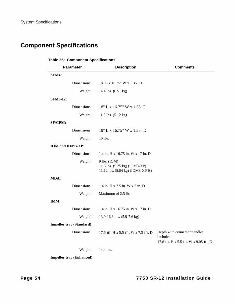
System Specifications
Component Specifications
Table 25: Component Specifications
Parameter Description Comments
SFM4:
Dimensions: 18" L x 16.75" W x 1.35" D
Weight: 14.4 lbs. (6.51 kg)
SFM3-12:
Dimensions: 18" L x 16.75" W x 1.35" D
Weight: 11.3 lbs. (5.12 kg)
SF/CPM:
Dimensions: 18" L x 16.75" W x 1.35" D
Weight: 10 lbs.
IOM and IOM3-XP:
Dimensions: 1.4 in. H x 16.75 in. W x 17 in. D
Weight: 9 lbs. (IOM)11.6 lbs. (5.25 kg) (IOM3-XP)11.12 lbs. (5.04 kg) (IOM3-XP-B)
MDA:
Dimensions: 1.4 in. H x 7.5 in. W x 7 in. D
Weight: Maximum of 2.5 lb.
IMM:
Dimensions: 1.4 in. H x 16.75 in. W x 17 in. D
Weight: 13.0-16.8 lbs. (5.9-7.6 kg)
Impeller tray (Standard):
Dimensions: 17.6 in. H x 5.5 in. W x 7.3 in. D Depth with connector/handles included:17.6 in. H x 5.5 in. W x 9.05 in. D
Weight: 14.4 lbs.
Impeller tray (Enhanced):
Page 54 7750 SR-12 Installation Guide
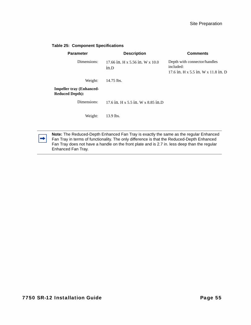
Site Preparation
Dimensions: 17.66 in. H x 5.56 in. W x 10.0
in.DDepth with connector/handles included:17.6 in. H x 5.5 in. W x 11.8 in. D
Weight: 14.75 lbs.
Impeller tray (Enhanced-Reduced Depth):
Dimensions: 17.6 in. H x 5.5 in. W x 8.85 in.D
Weight: 13.9 lbs.
Table 25: Component Specifications
Parameter Description Comments
Note: The Reduced-Depth Enhanced Fan Tray is exactly the same as the regular Enhanced Fan Tray in terms of functionality. The only difference is that the Reduced-Depth Enhanced Fan Tray does not have a handle on the front plate and is 2.7 in. less deep than the regular Enhanced Fan Tray.
7750 SR-12 Installation Guide Page 55

System Specifications
The Equipment Rack
The router must be installed in a rack. It cannot operate from a tabletop or floor. It can be front or middle mounted in many types of racks, including the following:
• Standard 19-inch (48.26 cm) equipment rack
• Standard telco rack (four-post)
Follow the equipment rack manufacturer’s instructions for proper rack installation.
The equipment rack rail mounting holes must align with the mounting holes on the chassis mounting brackets. The 7750 SR-12 mounting brackets are factory installed for a front mount in a 19-inch rack.
Required tools:
• #2 Phillips screwdriver
• Flathead screwdriver
• Anti-static bags, mats, and packaging
• ESD wrist strap
Page 56 7750 SR-12 Installation Guide

Site Preparation
Rack Clearance Requirements
Allow at least 3-inch clearance on the sides of the rack for proper airflow intake. Allow at least 20 inches in the front and rear of the rack for maintenance access. You will need this amount of space to remove and install SF/CPMs, IOMs, MDAs, and air filters in the front and to remove and install the cooling trays and DC PEMs in the rear.
Figure 8: Chassis Clearance Requirements (Top View)
FRONT
REAR
3” ALL SIDES
20” FRONTREQUIRED FOR MAINTENANCE
RECOMMENDED FOR AIR FLOWINTAKE
20” REARREQUIRED FOR MAINTENANCE
3” ALL SIDESRECOMMENDED FOR AIR FLOWINTAKE
3” ALL SIDESRECOMMENDED O AIR FLOWINTAKE
RECOMMENDED O AIR FLOW INTAKE
3” ALL SIDES
7750 SR-12 Installation Guide Page 57
Safety Considerations
Safety Considerations
Placement
Grounding
Warning:
• Install the 7750 SR-12 chassis in standard-sized equipment racks. The 7750 SR-12 is shipped with the 19-inch rack mounting brackets installed.
• Install the 7750 SR-12 chassis in a clean, dry, ventilated, and temperature-controlled rooms.• Verify that the rack is properly bolted and braced and grounded to a grounding electrode.• Install the chassis into the equipment rack before installing components.
Warning:
• The router and equipment rack must be properly grounded. • Chassis ground cables are not included. For an AC power shelf, use only power cords that have
a grounding (earthing) path. Main grounding (earthing) connection points are through the IEC60320 appliance inlets. Grounding (earthing) points on the sides of the equipment are for equipotential bonding only and are safety grounding (earthing) points for the equipment. Lack of proper grounding (earthing) of the equipment may result in a safety hazard and excessive electromagnetic emissions.
• The grounding of the 7750 SR-12 recommended in the installation manual and the parts provided in the accessories kit is based on CSA and NEBS guidelines. Alternate ground connections may also be applicable. Ultimately, the grounding of the 7750 SR-12 shall comply with all local codes and ordinances where the 7750 SR-12 is installed.
• The ground conductor must be #2 AWG minimum. If input cables are larger than #2 AWG, use an equivalent size ground cable. Example: If a single 2/0 cable size is used for input DC power, use the same 2/0 cable size for grounding. Or, if (2) #2 AWG cables are used on inputs, use a single 2/0 size ground cable.
• Electrostatic discharge (ESD) damage can occur if components are mishandled.• Always wear an ESD-preventive wrist or ankle strap in contact with bare skin. Always connect
the ESD strap (with banana plug) to the ESD connection socket (grounding jack) on the front of the chassis.
Page 58 7750 SR-12 Installation Guide
Site Preparation
Cabling
Power
Warning:
• To comply with the GR-1089-CORE, Issue 06, requirement R4-9 [31] standard for electromagnetic compatibility and safety, all intra-building ports are specified for use with shielded and grounded cables at both ends.
• The intra-building port(s) of the equipment or sub-assembly is suitable for connection to intra-building or unexposed wiring or cabling only. The intra-building port(s) of the equipment or sub-assembly must not be metallically connected to interfaces that connect to the Outside Plant (OSP) or its wiring or to equipment in an Isolated Bonding Network (IBN) unless the wiring passes through an SPCW as defined in GR-295. These interfaces are designed for use as intra-building interfaces only (Type 2 or Type 4 ports as described in GR-1089-CORE, Issue 6) and require isolation from the exposed OSP cabling. The addition of primary protectors is not sufficient protection in order to connect these interfaces metallically to OSP wiring. For equipment installed in an IBN, use Mesh-BN, Mesh-IBN, or Chain-IBN. Equipment rearrangements shall maintain the existing bonding topology.
• Bare conductors must be coated with an appropriate antioxidant compound before crimp connections are made. All unplated connectors, braided strap, and bus bars must be brought to a bright finish and then coated with an antioxidant before they are connected.
• The equipment under test (EUT) is specified for DC-I or DC-C power configurations. In the DC-C configuration, the ampacity of the conductor connecting the equipment frame to the BR conductor shall be equal to or greater than the ampacity of the associated BR conductor. The battery returns must remain isolated until they reach the main power bus.
Warning:
• Only service electrical personnel should perform wiring and cabling to the system.• All power to the equipment rack or cabinet should be disconnected before the installation.• The power cable(s) must be copper and meet your local electric code requirements.• The circuit breaker is not intended to be used as the chassis ON/OFF switch. Disconnect the
power from the power source to remove power.• The 7750 SR-12 router with DC power entry modules should be installed only in restricted
access areas (such as dedicated equipment rooms and electrical closets).
7750 SR-12 Installation Guide Page 59
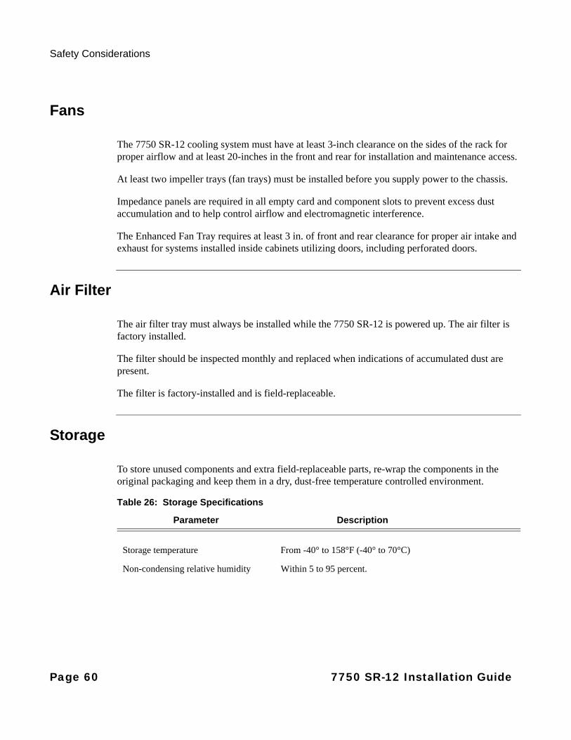
Safety Considerations
Fans
The 7750 SR-12 cooling system must have at least 3-inch clearance on the sides of the rack for proper airflow and at least 20-inches in the front and rear for installation and maintenance access.
At least two impeller trays (fan trays) must be installed before you supply power to the chassis.
Impedance panels are required in all empty card and component slots to prevent excess dust accumulation and to help control airflow and electromagnetic interference.
The Enhanced Fan Tray requires at least 3 in. of front and rear clearance for proper air intake and exhaust for systems installed inside cabinets utilizing doors, including perforated doors.
Air Filter
The air filter tray must always be installed while the 7750 SR-12 is powered up. The air filter is factory installed.
The filter should be inspected monthly and replaced when indications of accumulated dust are present.
The filter is factory-installed and is field-replaceable.
Storage
To store unused components and extra field-replaceable parts, re-wrap the components in the original packaging and keep them in a dry, dust-free temperature controlled environment.
Table 26: Storage Specifications
Parameter Description
Storage temperature From -40° to 158°F (-40° to 70°C)
Non-condensing relative humidity Within 5 to 95 percent.
Page 60 7750 SR-12 Installation Guide
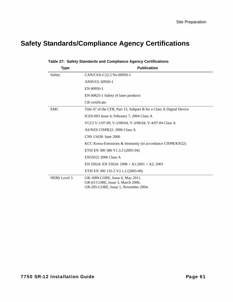
Site Preparation
Safety Standards/Compliance Agency Certifications
Table 27: Safety Standards and Compliance Agency Certifications
Type Publication
Safety CAN/CSA-C22.2 No 60950-1
ANSI/UL 60950-1
EN 60950-1
EN 60825-1 Safety of laser products
CB certificate
EMC Title 47 of the CFR, Part 15, Subpart B for a Class A Digital Device
ICES-003 Issue 4, February 7, 2004 Class A
VCCI V-1/07.09, V-2/08/04, V-3/08.04, V-4/07.04 Class A
AS/NZS CISPR22: 2006 Class A
CNS 13438: June 2006
KCC Korea-Emissions & Immunity (in accordance CISPR/KN22)
ETSI EN 300 386 V1.3.3 (2005-04)
EN55022 2006 Class A
EN 55024: EN 55024: 1998 + A1:2001 + A2: 2003
ETSI EN 300 132-2 V2.1.2 (2003-09)
NEBS Level 3 GR-1089-CORE, Issue 6, May 2011. GR-63-CORE, Issue 3, March 2006.GR-295-CORE, Issue 1, November 2004.
7750 SR-12 Installation Guide Page 61
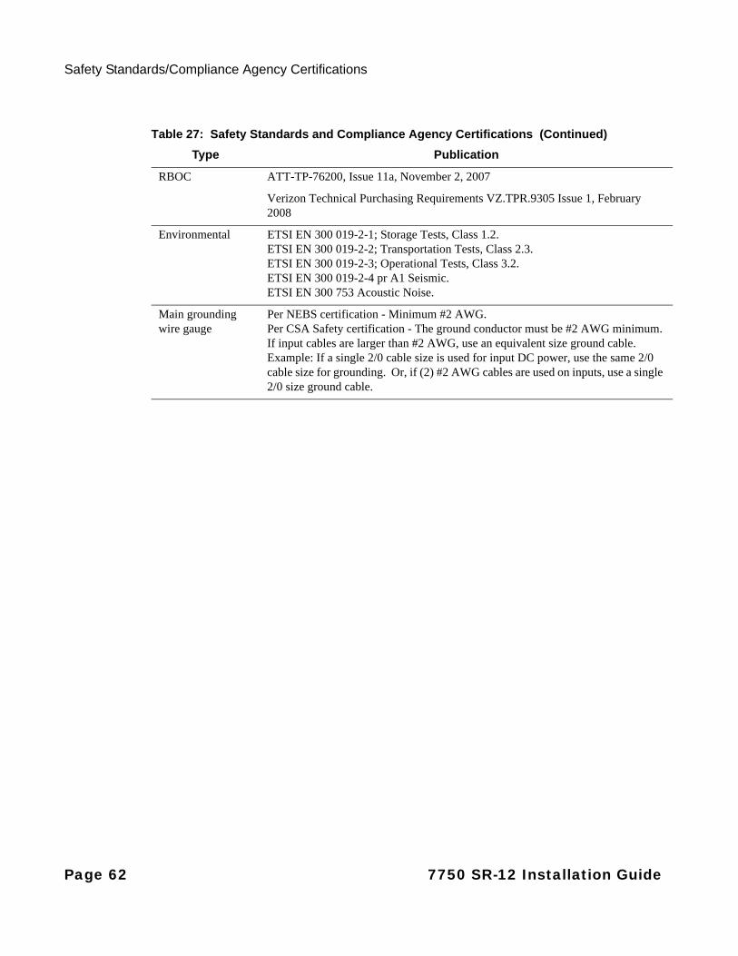
Safety Standards/Compliance Agency Certifications
RBOC ATT-TP-76200, Issue 11a, November 2, 2007
Verizon Technical Purchasing Requirements VZ.TPR.9305 Issue 1, February 2008
Environmental ETSI EN 300 019-2-1; Storage Tests, Class 1.2.ETSI EN 300 019-2-2; Transportation Tests, Class 2.3.ETSI EN 300 019-2-3; Operational Tests, Class 3.2.ETSI EN 300 019-2-4 pr A1 Seismic.ETSI EN 300 753 Acoustic Noise.
Main grounding wire gauge
Per NEBS certification - Minimum #2 AWG. Per CSA Safety certification - The ground conductor must be #2 AWG minimum. If input cables are larger than #2 AWG, use an equivalent size ground cable. Example: If a single 2/0 cable size is used for input DC power, use the same 2/0 cable size for grounding. Or, if (2) #2 AWG cables are used on inputs, use a single 2/0 size ground cable.
Table 27: Safety Standards and Compliance Agency Certifications (Continued)
Type Publication
Page 62 7750 SR-12 Installation Guide
Installing the 7750 SR-12
In This Chapter
This chapter provides information to rack mount a 7750 SR-12 chassis.
This chapter provides information on the following topics:
• Unpacking the Chassis on page 64
• Rack Mounting the Chassis on page 67
• Installing the Cable Management System on page 70
• Making the Chassis Ground Connection on page 73
• Installing Impeller Trays on page 79
7750 SR-12 Installation Guide Page 63
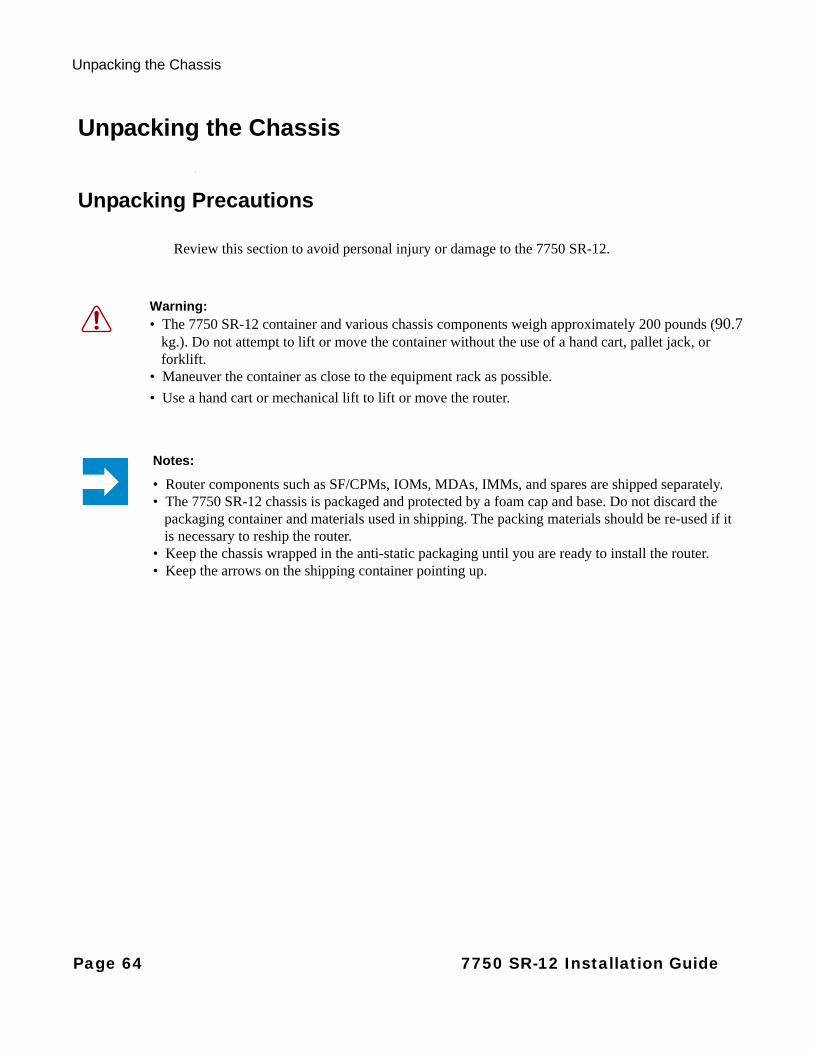
Unpacking the Chassis
Unpacking the Chassis
Unpacking Precautions
Review this section to avoid personal injury or damage to the 7750 SR-12.
Warning: • The 7750 SR-12 container and various chassis components weigh approximately 200 pounds (90.7
kg.). Do not attempt to lift or move the container without the use of a hand cart, pallet jack, or forklift.
• Maneuver the container as close to the equipment rack as possible.
• Use a hand cart or mechanical lift to lift or move the router.
Notes:
• Router components such as SF/CPMs, IOMs, MDAs, IMMs, and spares are shipped separately.• The 7750 SR-12 chassis is packaged and protected by a foam cap and base. Do not discard the
packaging container and materials used in shipping. The packing materials should be re-used if it is necessary to reship the router.
• Keep the chassis wrapped in the anti-static packaging until you are ready to install the router.• Keep the arrows on the shipping container pointing up.
Page 64 7750 SR-12 Installation Guide
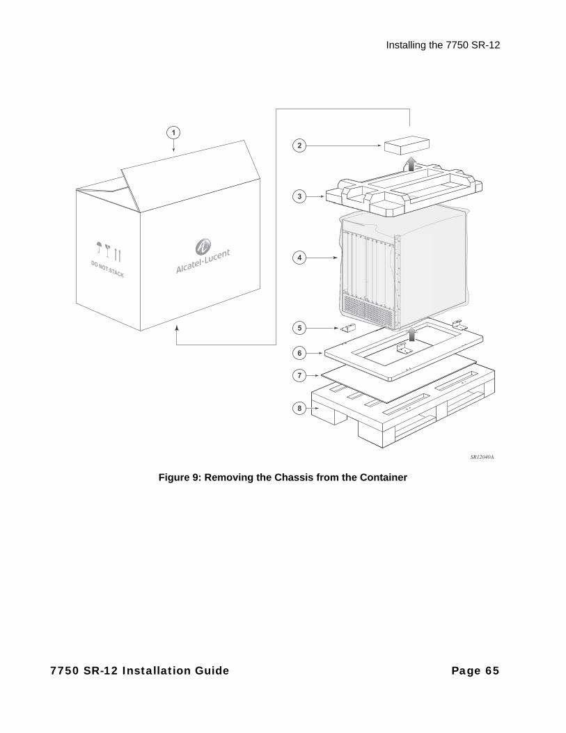
Installing the 7750 SR-12
Figure 9: Removing the Chassis from the Container
DO NOT STACK
4
SR12040A
3
6
7
8
5
2
1
7750 SR-12 Installation Guide Page 65
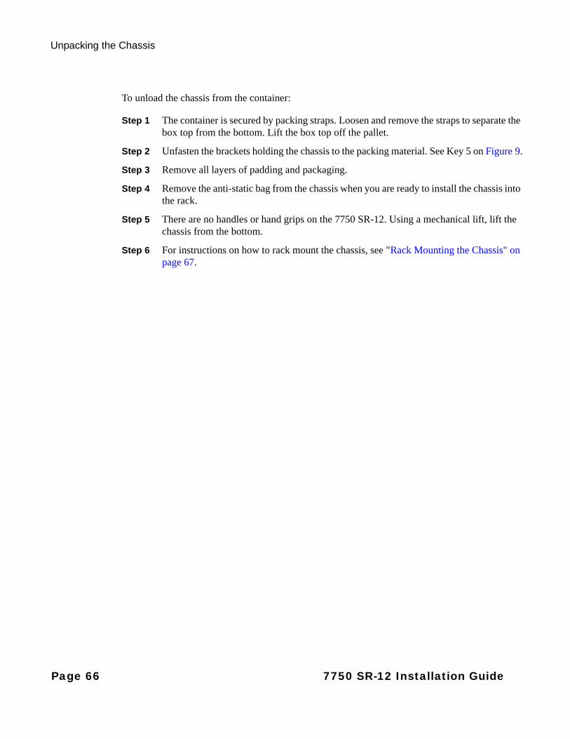
Unpacking the Chassis
To unload the chassis from the container:
Step 1 The container is secured by packing straps. Loosen and remove the straps to separate the box top from the bottom. Lift the box top off the pallet.
Step 2 Unfasten the brackets holding the chassis to the packing material. See Key 5 on Figure 9.
Step 3 Remove all layers of padding and packaging.
Step 4 Remove the anti-static bag from the chassis when you are ready to install the chassis into the rack.
Step 5 There are no handles or hand grips on the 7750 SR-12. Using a mechanical lift, lift the chassis from the bottom.
Step 6 For instructions on how to rack mount the chassis, see "Rack Mounting the Chassis" on page 67.
Page 66 7750 SR-12 Installation Guide

Installing the 7750 SR-12
Rack Mounting the Chassis
The 7750 SR-12 router is designed for front and middle-mount installation into a 19-inch rack. The rack mounting hardware (including rack bolts) is factory installed to front-mount the chassis in a 19-inch rack. The screws that are used to attach the rack-mount brackets may be re-used if moving the brackets to the front mounting position. These screws contain a thread-locking adhesive and can be re-used approximately 5 times, depending upon the condition of the adhesive. If the condition of the adhesive is in question, additional thread-locking adhesive can be applied, at the customers discretion.
Required tools:
• Use a screwdriver to loosen and tighten the mounting bracket bolts.
Before you begin, verify:
• The equipment rack is securely installed, anchored, and grounded. Refer to the rack manufacturer’s documentation for instructions.
• Any power to the rack is OFF.
Danger:
• Only trained and qualified personnel should install or replace this chassis and chassis components.
Caution:
• There are no handles or hand grips on the 7750 SR-12. Lift the router from underneath. Do not lift the router by the internal chassis frame.
• When rack mounting the 7750 SR-12 in an equipment rack, do not stack other 7750 SR-12 units or any other equipment directly on top (where the bottom unit is supporting other devices). Each unit must be secured into the rack with the appropriate mounting apparatus.
7750 SR-12 Installation Guide Page 67
Rack Mounting the Chassis
Figure 10: Installing the Chassis into an Equipment Rack
3
2
1
SR12005A
Table 28: Rack Mounting the 7750 SR-12 Chassis
Key Description
1 Equipment rack
2 Rack mounting screws
3 Rack mounting bracket
Page 68 7750 SR-12 Installation Guide
Installing the 7750 SR-12
To install the chassis into the rack:
Step 1 With at least two people, or, if necessary, using a hand cart, pallet jack, or forklift, position the chassis in front of the rack.
Step 2 With one person in front of the rack and one behind the rack, lift the 7750 SR-12 from the bottom and position it in the rack.
Step 3 (Optional) Slide the chassis on top of the shelf/bar.
Step 4 Align the mounting holes on each bracket to the rack rail. Insert a screw into each hole in the mounting bracket and tighten. Do not skip any holes.
7750 SR-12 Installation Guide Page 69

Installing the Cable Management System
Installing the Cable Management System
The 7750 SR-12 chassis can accommodate two cable management trays. The trays are mounted horizontally on the front of the chassis, above and below the chassis card slots (card cage).
The following instructions assume that the chassis rack mounting brackets remain in the front-mounting position, as they are shipped from the factory. The cable management trays are shipped with shims screwed into the brackets. Remove the shims if the 7750 SR-12 chassis is front-mounted.
The integral cable management tray mounting brackets align with mounting holes located on each side of the chassis, above and below the card cage (Figure 11 on page 71).
If the chassis rack mounting brackets are removed and relocated to accommodate a mid-mount chassis installation, then a shim must be placed between each cable management tray mounting brackets and the chassis wall. Shims fill the gaps between the chassis wall and the cable management tray brackets that would otherwise be occupied by the rack mounting bracket (which were removed and reinstalled at the mid-line).
Key 2 on Figure 11 illustrates the cable management system installation with the chassis front mounted in an equipment rack.
Key 3 on Figure 11 illustrates the cable management system installation with the shim when the chassis is mid-mounted in an equipment rack.
The cable pegs are accessed by flipping the upper access door upward and the lower access door downward.
Mount the chassis in the equipment rack before installing the cable management trays.
The cable tray manages the cables leading from slots 2 through 9 as well as from the SF/CPM slots A and B. Cables from IOM slots 1 and 10 are not managed by this tray design. To prevent fiber damage when module ejector levers are opened and closed, cables from IOM slots 1 and 10 should be routed directly toward the outside of the chassis and into the customer-provided routing trays (FIGURE 11).
Page 70 7750 SR-12 Installation Guide
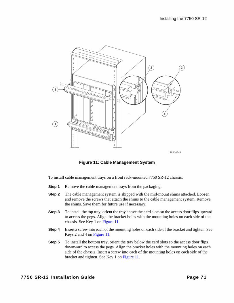
Installing the 7750 SR-12
Figure 11: Cable Management System
To install cable management trays on a front rack-mounted 7750 SR-12 chassis:
Step 1 Remove the cable management trays from the packaging.
Step 2 The cable management system is shipped with the mid-mount shims attached. Loosen and remove the screws that attach the shims to the cable management system. Remove the shims. Save them for future use if necessary.
Step 3 To install the top tray, orient the tray above the card slots so the access door flips upward to access the pegs. Align the bracket holes with the mounting holes on each side of the chassis. See Key 1 on Figure 11.
Step 4 Insert a screw into each of the mounting holes on each side of the bracket and tighten. See Keys 2 and 4 on Figure 11.
Step 5 To install the bottom tray, orient the tray below the card slots so the access door flips downward to access the pegs. Align the bracket holes with the mounting holes on each side of the chassis. Insert a screw into each of the mounting holes on each side of the bracket and tighten. See Key 1 on Figure 11.
SR12026B
1
1
2 3
4
7750 SR-12 Installation Guide Page 71
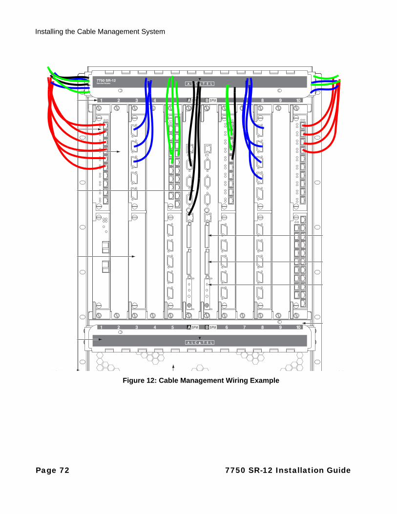
Installing the Cable Management System
Figure 12: Cable Management Wiring Example
3
1
2
4
5
1
6
7
11
10
10
2
Page 72 7750 SR-12 Installation Guide

Installing the 7750 SR-12
Making the Chassis Ground Connection
The 7750 SR-12 chassis must be grounded properly for all applications. Alcatel-Lucent support both CBN (common ground) and IBN (isolated ground) implementations for the chassis. Choose the size of the grounding cables according to the type of PEM used, the Agency/Country requirements of your location, and the lug sizing.
Grounding lugs are provided for the chassis ground connection. If the lugs are missing or misplaced, prepare your ground cable with a standard barrel, 2-hole lug with two 1/4-inch (.635 cm) diameter holes on a 5/8-inch (1.5875 cm) spacing. Grounding lug(s) are shipped with the chassis.
Grounding cables are not provided with the chassis. To make sure that the equipment is connected to earth ground, follow the instructions to prepare the ground wire. The length of the grounding wire depends on the location of the router and proximity to the proper grounding facilities.
Washers and screws for the grounding lugs are part of the following 7750 SR-12 Accessories Kits:
• 3HE00147BAAA (PEM1)
• 3HE00147CAAA (PEM3)
In the case of a PEM-3 upgrade, the washers and screws for the grounding lugs are part of the Accessory Kits:
• 3HE4606AAAA
• 3HE4608AAAA
Washers and screws can also be purchased as a Lug Kit: 3HE01882BAAAA.
Two grounding screws are located on the rear side of the chassis, on the top left-hand side.
Danger: Only trained and qualified personnel should install or replace this chassis and chassis components.
Note: When wiring any Alcatel-Lucent 7750 router, the ground connection must always be made first and disconnected last.
7750 SR-12 Installation Guide Page 73
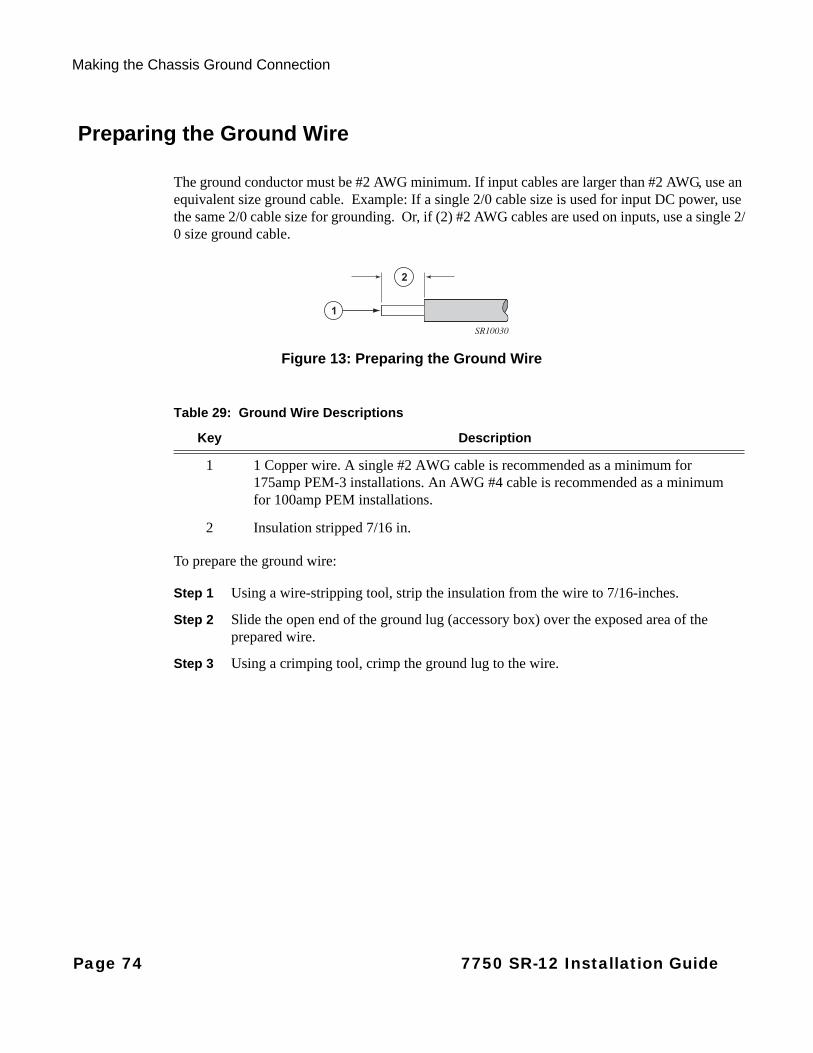
Making the Chassis Ground Connection
Preparing the Ground Wire
The ground conductor must be #2 AWG minimum. If input cables are larger than #2 AWG, use an equivalent size ground cable. Example: If a single 2/0 cable size is used for input DC power, use the same 2/0 cable size for grounding. Or, if (2) #2 AWG cables are used on inputs, use a single 2/0 size ground cable.
Figure 13: Preparing the Ground Wire
To prepare the ground wire:
Step 1 Using a wire-stripping tool, strip the insulation from the wire to 7/16-inches.
Step 2 Slide the open end of the ground lug (accessory box) over the exposed area of the prepared wire.
Step 3 Using a crimping tool, crimp the ground lug to the wire.
1
2
SR10030
Table 29: Ground Wire Descriptions
Key Description
1 1 Copper wire. A single #2 AWG cable is recommended as a minimum for 175amp PEM-3 installations. An AWG #4 cable is recommended as a minimum for 100amp PEM installations.
2 Insulation stripped 7/16 in.
Page 74 7750 SR-12 Installation Guide
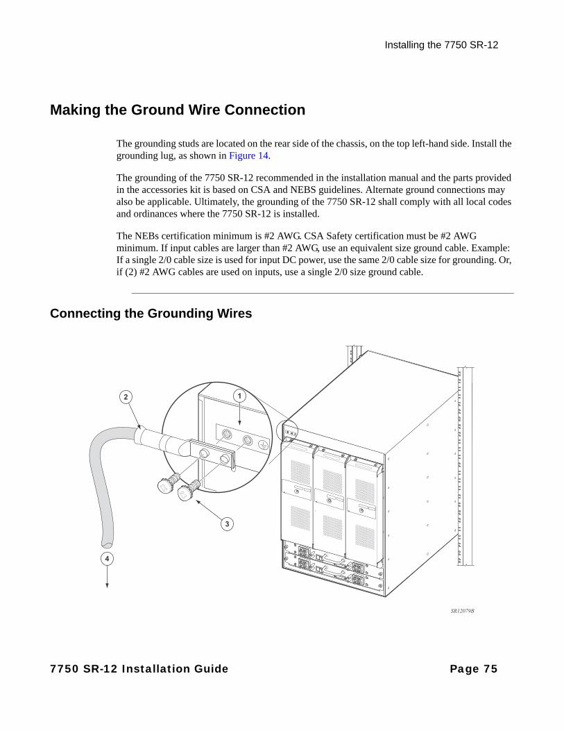
Installing the 7750 SR-12
Making the Ground Wire Connection
The grounding studs are located on the rear side of the chassis, on the top left-hand side. Install the grounding lug, as shown in Figure 14.
The grounding of the 7750 SR-12 recommended in the installation manual and the parts provided in the accessories kit is based on CSA and NEBS guidelines. Alternate ground connections may also be applicable. Ultimately, the grounding of the 7750 SR-12 shall comply with all local codes and ordinances where the 7750 SR-12 is installed.
The NEBs certification minimum is #2 AWG. CSA Safety certification must be #2 AWG minimum. If input cables are larger than #2 AWG, use an equivalent size ground cable. Example: If a single 2/0 cable size is used for input DC power, use the same 2/0 cable size for grounding. Or, if (2) #2 AWG cables are used on inputs, use a single 2/0 size ground cable.
Connecting the Grounding Wires
3
2
4
1
SR12079B
7750 SR-12 Installation Guide Page 75

Making the Chassis Ground Connection
Figure 14: Connecting the Grounding Lug on a Router
Page 76 7750 SR-12 Installation Guide
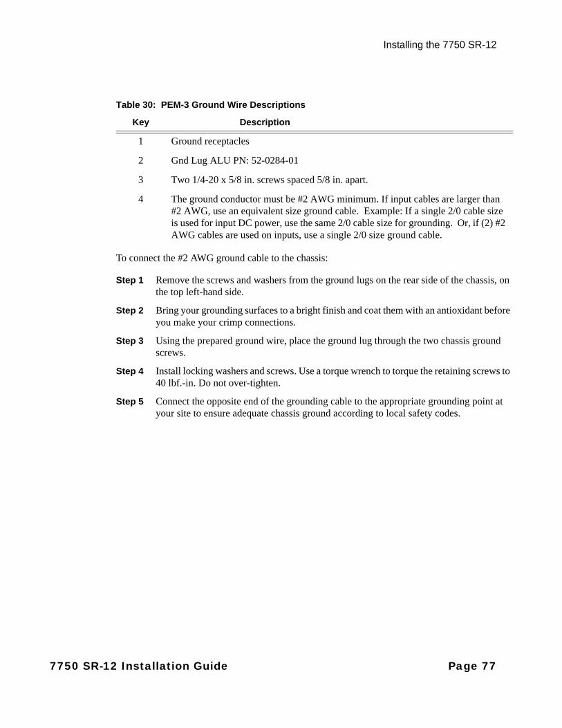
Installing the 7750 SR-12
To connect the #2 AWG ground cable to the chassis:
Step 1 Remove the screws and washers from the ground lugs on the rear side of the chassis, on the top left-hand side.
Step 2 Bring your grounding surfaces to a bright finish and coat them with an antioxidant before you make your crimp connections.
Step 3 Using the prepared ground wire, place the ground lug through the two chassis ground screws.
Step 4 Install locking washers and screws. Use a torque wrench to torque the retaining screws to 40 lbf.-in. Do not over-tighten.
Step 5 Connect the opposite end of the grounding cable to the appropriate grounding point at your site to ensure adequate chassis ground according to local safety codes.
Table 30: PEM-3 Ground Wire Descriptions
Key Description
1 Ground receptacles
2 Gnd Lug ALU PN: 52-0284-01
3 Two 1/4-20 x 5/8 in. screws spaced 5/8 in. apart.
4 The ground conductor must be #2 AWG minimum. If input cables are larger than #2 AWG, use an equivalent size ground cable. Example: If a single 2/0 cable size is used for input DC power, use the same 2/0 cable size for grounding. Or, if (2) #2 AWG cables are used on inputs, use a single 2/0 size ground cable.
7750 SR-12 Installation Guide Page 77
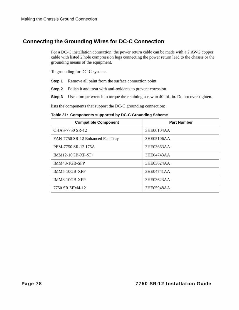
Making the Chassis Ground Connection
Connecting the Grounding Wires for DC-C Connection
For a DC-C installation connection, the power return cable can be made with a 2 AWG copper cable with listed 2 hole compression lugs connecting the power return lead to the chassis or the grounding means of the equipment.
To grounding for DC-C systems:
Step 1 Remove all paint from the surface connection point.
Step 2 Polish it and treat with anti-oxidants to prevent corrosion.
Step 3 Use a torque wrench to torque the retaining screw to 40 lbf.-in. Do not over-tighten.
lists the components that support the DC-C grounding connection:
Table 31: Components supported by DC-C Grounding Scheme
Compatible Component Part Number
CHAS-7750 SR-12 3HE00104AA
FAN-7750 SR-12 Enhanced Fan Tray 3HE05106AA
PEM-7750 SR-12 175A 3HE03663AA
IMM12-10GB-XP-SF+ 3HE04743AA
IMM48-1GB-SFP 3HE03624AA
IMM5-10GB-XFP 3HE04741AA
IMM8-10GB-XFP 3HE03623AA
7750 SR SFM4-12 3HE05948AA
Page 78 7750 SR-12 Installation Guide

Installing the 7750 SR-12
Installing Impeller Trays
Warnings and Notes
Warning:
• Immediately install the replacement fan tray upon removal of the old fan tray. If a longer maintenance time is required, power off the system.
• Do not mix Standard Fan Trays and Enhanced Fan Trays in the same chassis, except while performing a fan tray upgrade.
• Always keep your fingers away from rotating blades.
• Verify that the fan blades have stopped rotating before removing an impeller tray.
Caution:
• Do not mix Standard Fan Trays and Enhanced Fan Trays in the same chassis, except while performing a fan tray upgrade.
Notes:
• Three impeller trays are recommended for normal operation.
• There are three fan tray slots in the rear of the 7750 SR-12 chassis. The left slot is designated as fan tray #1, the middle slot is designated as fan tray #2, and the right slot is designated as fan tray #3.
• The trays are hot-swappable. The 7750 SR-12 chassis operates safely while you replace the fan tray for up to approximately 2 minutes at an ambient temperature of 95° F (35° C). If a longer maintenance time is required, power off the system to prevent overtemperature conditions.
• Immediately replace a tray as soon as an impeller failure is detected.
• In the event of a single impeller failure, the entire tray must be replaced.
• To remove and replace the trays you must have access to the rear of the chassis. You must have enough room, at least 20-inches, to pull the trays completely out of the slot.
• The Enhanced Fan Tray extends 3.990 inches max beyond the rear of the SR-12 and ESS-12 chassis. The Reduced-Depth Enhanced Fan Tray extends 2.0 inches max beyond the rear of the SR-12 and ESS-12 chassis.
7750 SR-12 Installation Guide Page 79
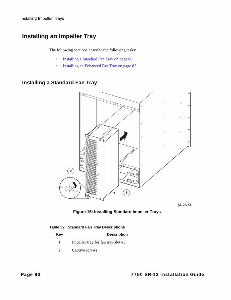
Installing Impeller Trays
Installing an Impeller Tray
The following sections describe the following tasks:
• Installing a Standard Fan Tray on page 80
• Installing an Enhanced Fan Tray on page 82
Installing a Standard Fan Tray
Figure 15: Installing Standard Impeller Trays
1
2
SR12025A
Table 32: Standard Fan Tray Descriptions
Key Description
1 Impeller tray for fan tray slot #3
2 Captive screws
Page 80 7750 SR-12 Installation Guide

Installing the 7750 SR-12
To install Standard Fan Trays:
Step 1 Remove the Standard Fan Trays from the protective packaging.
Step 2 Install the Standard Fan Tray in the right-most slot. Gripping the handle, orient the tray so the connector is on the top-right rear side. Slide the connector end into the slot until it is fully seated. Tighten the captive screws.
Step 3 Install the Standard Fan Tray in the middle slot.
Step 4 Install the Standard Fan Tray in the left-most slot.
7750 SR-12 Installation Guide Page 81

Installing Impeller Trays
Installing an Enhanced Fan Tray
Figure 16: Installing Enhanced Impeller Trays
1
2
SR12078A
Table 33: Enhanced Fan Tray Descriptions
Key Description
1 Impeller tray for fan tray slot #3
2 Captive screws
Page 82 7750 SR-12 Installation Guide
Installing the 7750 SR-12
To install Enhanced Fan Trays:
Step 1 Grip the Enhanced Fan Tray and slide the connector end into the slot until it is fully seated.
Step 2 Secure the tray into place by tightening the captive screws (Figure 16).
Step 3 Verify the Fan Status LED on the front panel of the active CPM. You can also verify by checking the Fan Status LED on the front plate of the Enhanced Fan Tray (green indicates normal operation).
Step 4 Install the Enhanced Fan Tray in the middle slot.
Step 5 Install the Enhanced Fan Tray in the left-most slot.
Notes: As part of the initialization and diagnostic startup, the Enhanced Fan Tray ramps to maximum fan speed for a brief period. Upon successful completion, the Enhanced Fan Tray slows down to the speed set by the SFM4, SFM3, SFM1/2s.
Note: The Reduced-Depth Enhanced Fan Tray is exactly the same as the regular Enhanced Fan Tray in terms of functionality. The only difference is that the Reduced-Depth Enhanced Fan Tray does not have a handle on the front plate and is 2.7 in. less deep than the regular Enhanced Fan Tray.
7750 SR-12 Installation Guide Page 83

Installing Impeller Trays
Page 84 7750 SR-12 Installation Guide
Installing Power Supplies
In This Chapter
This chapter provides information about installing DC power entry modules (PEMs) into the 7750 SR-12 router.
Instructions to wire external AC power shelves to DC PEMs are also provided.
This chapter provides information on the following topics:
• General Power Warnings and Notes on page 86
• Installing DC Power Entry Modules (PEMs) on page 88
• AC-Input Power Guidelines on page 111
• Monitoring AC Power on page 118
7750 SR-12 Installation Guide Page 85
General Power Warnings and Notes
General Power Warnings and Notes
Danger:
• Only qualified personnel should connect power cables.
• Before working on equipment that is connected to power, remove jewelry, (rings, necklaces, watches, etc.). When metal objects are in contact with power and ground, serious burns can occur or the object can be welded to the device.
• Turn off power at the power source before you install or remove power cords.
• You must use cables which meet local electrical code requirements.
• Make your ground connections first.
Warning: The SR/ESS-12 power subsystem is based on a diode-or’d design for redundancy purposes. For this reason, a small amount of voltage (relative to ground) of approximately 3-4 volts is measured/observed on the (-) return feed, even when the branch circuit and PEM Breaker are shut off (assuming the second PEM remains powered/on). If this is a concern during the upgrade process, follow the steps below:
Step 1 Shut the branch breaker/ fuse to the redundant PEM being replaced.
Step 2 Shut the breaker off on the PEM itself.
Step 3 Pull the PEM out of its slot. This ensures no remaining voltage on the return feed.
Step 4 Remove the return cable from the PEM that has been pulled out.
By removing the PEM prior to handling the return cable, no voltage remains on the line.
Warning:
• Do not install equipment that appears to be damaged.
• Impedance panels are required in all empty card and component slots to prevent excess dust accumulation and to help control airflow and electromagnetic interference. Impedance panels do not have board components or connector pins.
• Electrostatic discharge (ESD) damage can occur if components are mishandled. Always wear an ESD-preventive wrist or ankle strap and always connect an ESD strap to the grounding plug on the front of the chassis.
Page 86 7750 SR-12 Installation Guide
Installing Power Supplies
Notes:
• The 7750 SR-12 is shipped with two factory-installed DC PEMs. Installation instructions are provided in the chapter. Removal instructions are provided in "Appendix B: Field Replaceable Units" on page 159.
• For full redundancy, each power supply module should be attached to an independent power source with a dedicated circuit breaker.
• In the event of a power unit failure (DC PEM or AC rectifier or AC power shelf), the entire power unit must be replaced. There are no field serviceable parts inside the power modules.
7750 SR-12 Installation Guide Page 87

Installing DC Power Entry Modules (PEMs)
Installing DC Power Entry Modules (PEMs)
DC This section provides information and instructions to perform the following:
• "DC Power Warnings and Notes" on page 88
• "Installing a 175-Amp DC PEM-3" on page 91
• "Preparing Input Power Wiring for the 175-Amp PEM-3" on page 94
• "Installing a 100-Amp DC PEM" on page 100
• "Preparing DC-Input Power Wiring for the 100-Amp DC PEM" on page 102
DC Power Warnings and Notes
Special DC Wiring Notes
• The power wiring for the 100-Amp DC PEM and the 175-Amp DC PEM-3 for the SR-12/ESS-12 chassis are significantly different.
→ On the 100-Amp DC PEM, both -48VDC and RTN terminals are located on the left side, with -48VDC above the RTN.
→ On the 175-Amp PEM-3, the -48VDC and RTNs are separate and on opposite ends of the PEM. The -48VDC terminal block is located on the left side of the PEM and the RTN terminal block is on the right side.
• When you are upgrading from a 100-Amp DC PEM to a 175-Amp PEM-3, it is important to connect the RTN power lug to the right side terminal block. Connecting both the existing terminal lugs to the -48 VDC terminal block can result in arc welding (shorting) the terminal lugs to the block.
• The terminal lug spacing is the same on the 175-Amp PEM-3 and 100-Amp PEM. The terminal lugs for the PEM will fit on the terminal blocks for the PEM-3.
Page 88 7750 SR-12 Installation Guide

Installing Power Supplies
Notes:
• If the installer does not pay attention, the existing feeds can be physically connected (-48 VDC and -48VDC RTN) to the left side terminal block (-48 VDC) of the PEM-3 and short the -48VDC feed to the -48VDC RTN feed. The following warning label appears on the PEM-3. Remove the label after the installation.
• Follow the installation instructions Installing a 100-Amp DC PEM on page 100 and Installing a 175-Amp DC PEM-3 on page 91 making sure to follow all instructions on the labels and terminal blocks.
Danger:
• A suitable disconnect device must be provided in the DC branch, either a circuit breaker or switch that can be employed to disconnect power to the system during servicing.
• Before connecting or disconnecting ground or power wires to the chassis, ensure that power is removed from the DC circuit.
• On the PEM-3, the RTN and -48 VDC feeds are electrically joined. When power is applied to one feed, power is also present in the other feed.
• Confirm that the DC power source is OFF during installation. The power source should be a safety extra-low voltage (SELV) source.
• The 7750 SR-12 router with DC PEMs should be installed only in restricted access areas (such as dedicated equipment rooms and electrical closets) in accordance with Articles 110-26 and 110-27 of the most recent National Electrical Code ANSI/NFPA 70.
7750 SR-12 Installation Guide Page 89

Installing DC Power Entry Modules (PEMs)
Caution:
• Make sure you directly connect the 7750 SR-12 to the DC power supply system earthing electrode conductor or to a bonding jumper from an earthing terminal bar or bus to which the DC power supply system earthing electrode is connected.
• The DC power supply source must be located within the same premises as this equipment.
• There must be no switching or disconnecting devices in the earthed circuit conductor between the DC source and the point of connection of the earthing electrode conductor.
• The 7750 SR-12 PEM-3 has a breaker rating of 175 amps. If the current drawn by your system reaches or exceeds 175 amps, the breaker trips to protect the system.
Notes:
• The remote power source (circuit breaker panel, outlet, etc.) must be easily accessible.
• Cables are not provided. In the United States, use a minimum of #4 AWG, high strand count copper wire. If the 7750 router is located outside the USA, consult local and national electrical code for proper wire sizing.
• For the DC PEM terminal block, lugs are provided. If they are missing or misplaced, use a Panduit LCC F6-14A copper, standard barrel, 2-hole lug with two 1/4-inch (.635 cm) diameter holes on a 3/4-inch (1.905 cm) spacing (0.250-20 UNC).
• Two PEM slots are located at the bottom rear of the chassis (see "7450 ESS-12 Chassis Rear View" on page 19). The slots are not labeled but for documentation purposes the top slot is referred to as slot “1” and the bottom slot is referred to as slot “2”. For full redundancy two PEMs must be installed and each PEM must be attached to an independent power source with a dedicated circuit breaker.
• The 7750 SR-12 requires a minimum of one DC PEM to operate, but two are recommended for redundancy. When two PEMs are installed, they share the electrical load equally as long as both PEMs are operational. If one PEM fails, the remaining PEM provides the power the router requires for normal operation.
• For full redundancy, each power supply module should be attached to an independent power source with a dedicated circuit breaker.
• The 7750 SR-12 PEM-3 has a safety rating of 6450 watts. This rating indicates the potential output the PEM-3 can provide and the safety certification level.
Page 90 7750 SR-12 Installation Guide
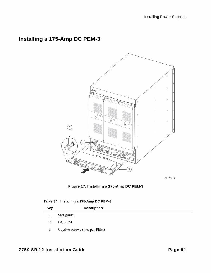
Installing Power Supplies
Installing a 175-Amp DC PEM-3
Figure 17: Installing a 175-Amp DC PEM-3
2
3
1
SR12081A
Table 34: Installing a 175-Amp DC PEM-3
Key Description
1 Slot guide
2 DC PEM
3 Captive screws (two per PEM)
7750 SR-12 Installation Guide Page 91
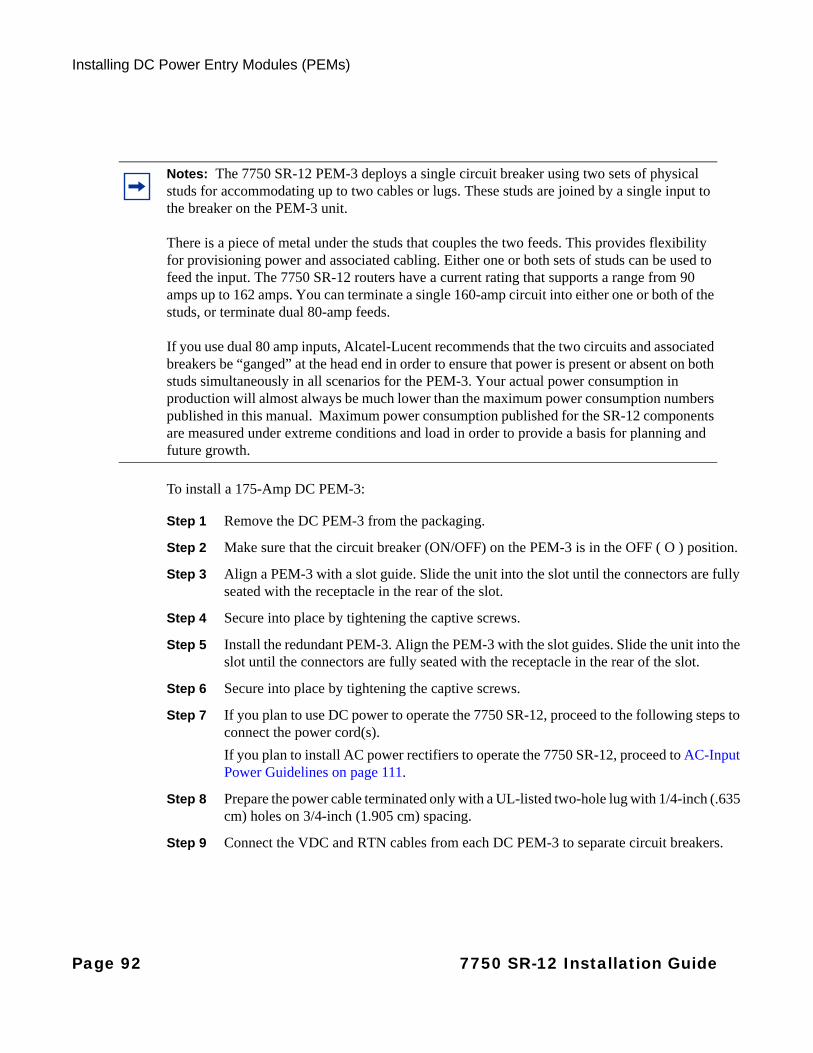
Installing DC Power Entry Modules (PEMs)
To install a 175-Amp DC PEM-3:
Step 1 Remove the DC PEM-3 from the packaging.
Step 2 Make sure that the circuit breaker (ON/OFF) on the PEM-3 is in the OFF ( O ) position.
Step 3 Align a PEM-3 with a slot guide. Slide the unit into the slot until the connectors are fully seated with the receptacle in the rear of the slot.
Step 4 Secure into place by tightening the captive screws.
Step 5 Install the redundant PEM-3. Align the PEM-3 with the slot guides. Slide the unit into the slot until the connectors are fully seated with the receptacle in the rear of the slot.
Step 6 Secure into place by tightening the captive screws.
Step 7 If you plan to use DC power to operate the 7750 SR-12, proceed to the following steps to connect the power cord(s).
If you plan to install AC power rectifiers to operate the 7750 SR-12, proceed to AC-Input Power Guidelines on page 111.
Step 8 Prepare the power cable terminated only with a UL-listed two-hole lug with 1/4-inch (.635 cm) holes on 3/4-inch (1.905 cm) spacing.
Step 9 Connect the VDC and RTN cables from each DC PEM-3 to separate circuit breakers.
Notes: The 7750 SR-12 PEM-3 deploys a single circuit breaker using two sets of physical studs for accommodating up to two cables or lugs. These studs are joined by a single input to the breaker on the PEM-3 unit.
There is a piece of metal under the studs that couples the two feeds. This provides flexibility for provisioning power and associated cabling. Either one or both sets of studs can be used to feed the input. The 7750 SR-12 routers have a current rating that supports a range from 90 amps up to 162 amps. You can terminate a single 160-amp circuit into either one or both of the studs, or terminate dual 80-amp feeds.
If you use dual 80 amp inputs, Alcatel-Lucent recommends that the two circuits and associated breakers be “ganged” at the head end in order to ensure that power is present or absent on both studs simultaneously in all scenarios for the PEM-3. Your actual power consumption in production will almost always be much lower than the maximum power consumption numbers published in this manual. Maximum power consumption published for the SR-12 components are measured under extreme conditions and load in order to provide a basis for planning and future growth.
Page 92 7750 SR-12 Installation Guide
Installing Power Supplies
The SR/ESS-12 power subsystem is a diode-or’d design for redundancy purposes. For this reason, the presence of a small amount of voltage (relative to ground) of approximately 3V to 4V will be measured/observed on the (-) return feed even when the branch circuit and PEM Breaker are shut off (assuming the second PEM remains powered/on). If a customer is concerned about this when upgrading, perform the following steps:
Step 1 Shut branch breaker/fuse to the redundant PEM being replaced.
Step 2 Shut the breaker off on the PEM itself.
Step 3 Pull the PEM out of its slot (this will ensure no remaining voltage on return feed).
Step 4 Remove return cable from the PEM that has been removed.
By removing the PEM prior to handling the return cable, you ensure that no voltage remains on the line.
7750 SR-12 Installation Guide Page 93

Installing DC Power Entry Modules (PEMs)
Preparing Input Power Wiring for the 175-Amp PEM-3
PREPARING THE POWER CABLE FOR THE 175-AMP DC PEM-3
Figure 18 displays the DC terminal block stud dimensions and spacing measurements. Connect the VCD and RTN studs on the DC terminal block with power cables terminated with 0.250-20 UNC lugs (Figure 19). Use two washers sized to accommodate the 1/4 in. studs and two 0.250-20 kepnuts.
The other non-terminated end of the power cables must be prepared according to your local safety codes. The length of the power cable depends on the location of the router and proximity to the power source.
Warning:
• Ensure that all power is OFF from the DC circuit. Locate the circuit breaker on the panel board that services the DC circuit. Switch the circuit breaker to the OFF position.
• When wiring the unit, the ground connection must always be made first and disconnected last.
• The proper wiring sequence is ground/negative to ground/negative and positive/return to positive/return.
• Consult your local and national electrical codes to calculate the appropriate cable sizing.
Page 94 7750 SR-12 Installation Guide
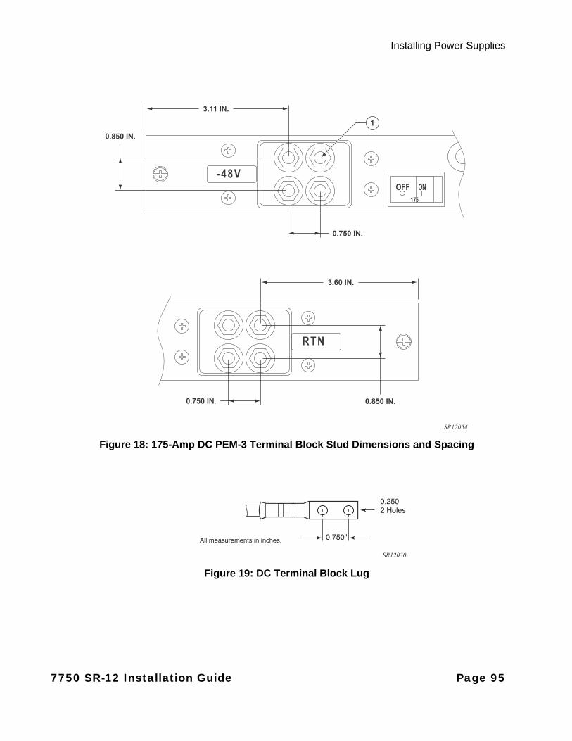
Installing Power Supplies
Figure 18: 175-Amp DC PEM-3 Terminal Block Stud Dimensions and Spacing
Figure 19: DC Terminal Block Lug
SR12054
3.11 IN.
0.850 IN.
3.60 IN.
0.750 IN.
0.850 IN.0.750 IN.
1
0.750"
0.2502 Holes
All measurements in inches.
SR12030
7750 SR-12 Installation Guide Page 95

Installing DC Power Entry Modules (PEMs)
Figure 20: Preparing the DC Cable
To prepare the cable (Figure 20):
Step 1 Using a wire-stripping tool, strip the insulation from the wire to 7/16-inches.
Step 2 Locate the lug in the accessory box. Slide the open end of the lug over the exposed area of the prepared wire.
Step 3 Using a crimping tool, crimp the lug to the wire.
1
2
SR10030
Table 35: DC Power Cable
Key Description
1 Copper wire
2 Insulation stripped 7/16-inch
Page 96 7750 SR-12 Installation Guide
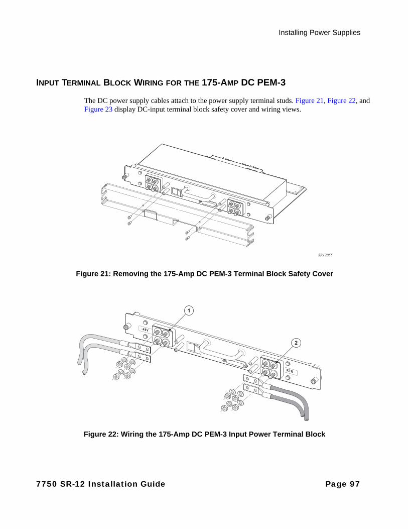
Installing Power Supplies
INPUT TERMINAL BLOCK WIRING FOR THE 175-AMP DC PEM-3
The DC power supply cables attach to the power supply terminal studs. Figure 21, Figure 22, and Figure 23 display DC-input terminal block safety cover and wiring views.
Figure 21: Removing the 175-Amp DC PEM-3 Terminal Block Safety Cover
Figure 22: Wiring the 175-Amp DC PEM-3 Input Power Terminal Block
SR12055
2
1
7750 SR-12 Installation Guide Page 97
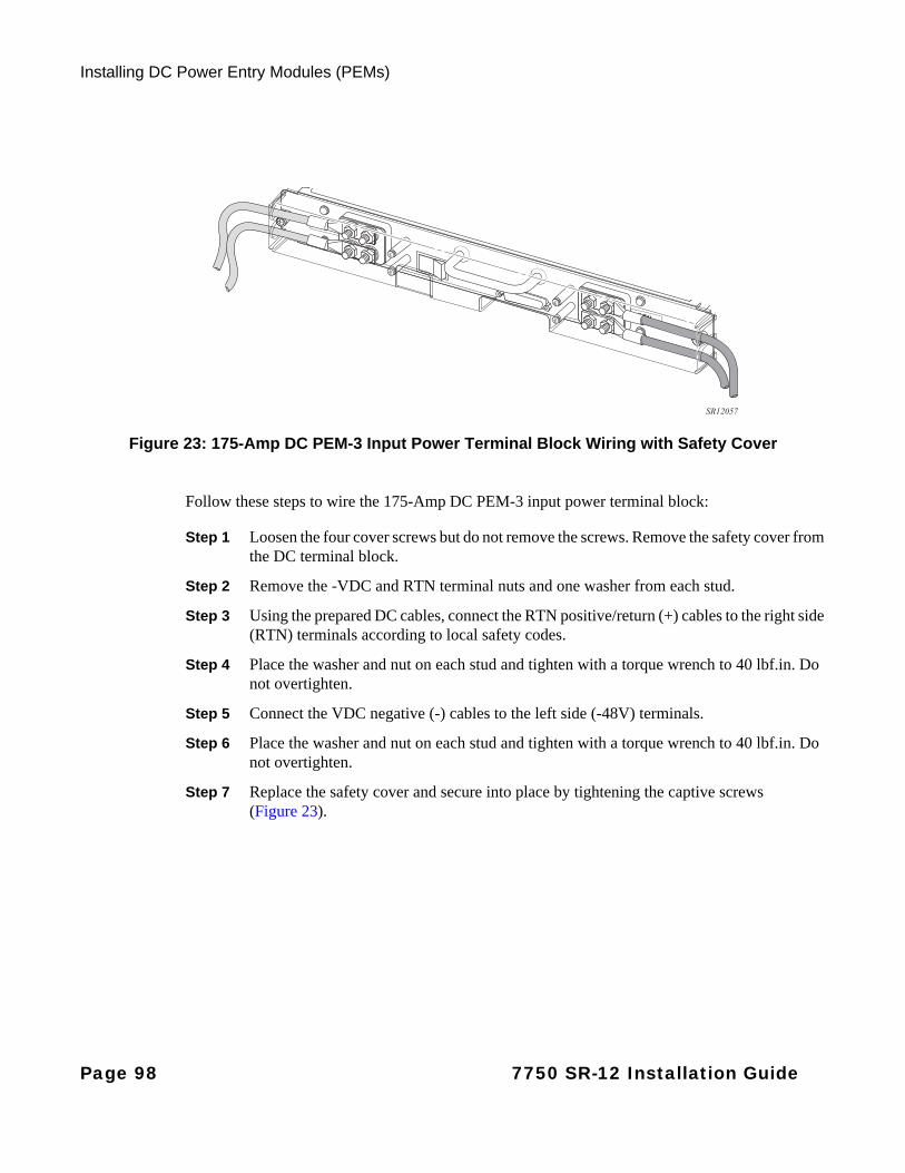
Installing DC Power Entry Modules (PEMs)
Figure 23: 175-Amp DC PEM-3 Input Power Terminal Block Wiring with Safety Cover
Follow these steps to wire the 175-Amp DC PEM-3 input power terminal block:
Step 1 Loosen the four cover screws but do not remove the screws. Remove the safety cover from the DC terminal block.
Step 2 Remove the -VDC and RTN terminal nuts and one washer from each stud.
Step 3 Using the prepared DC cables, connect the RTN positive/return (+) cables to the right side (RTN) terminals according to local safety codes.
Step 4 Place the washer and nut on each stud and tighten with a torque wrench to 40 lbf.in. Do not overtighten.
Step 5 Connect the VDC negative (-) cables to the left side (-48V) terminals.
Step 6 Place the washer and nut on each stud and tighten with a torque wrench to 40 lbf.in. Do not overtighten.
Step 7 Replace the safety cover and secure into place by tightening the captive screws (Figure 23).
SR12057
Page 98 7750 SR-12 Installation Guide
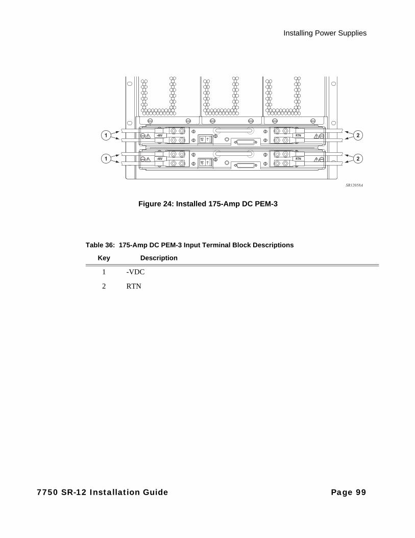
Installing Power Supplies
Figure 24: Installed 175-Amp DC PEM-3
SR12058A
1
1
2
2
Table 36: 175-Amp DC PEM-3 Input Terminal Block Descriptions
Key Description
1 -VDC
2 RTN
7750 SR-12 Installation Guide Page 99
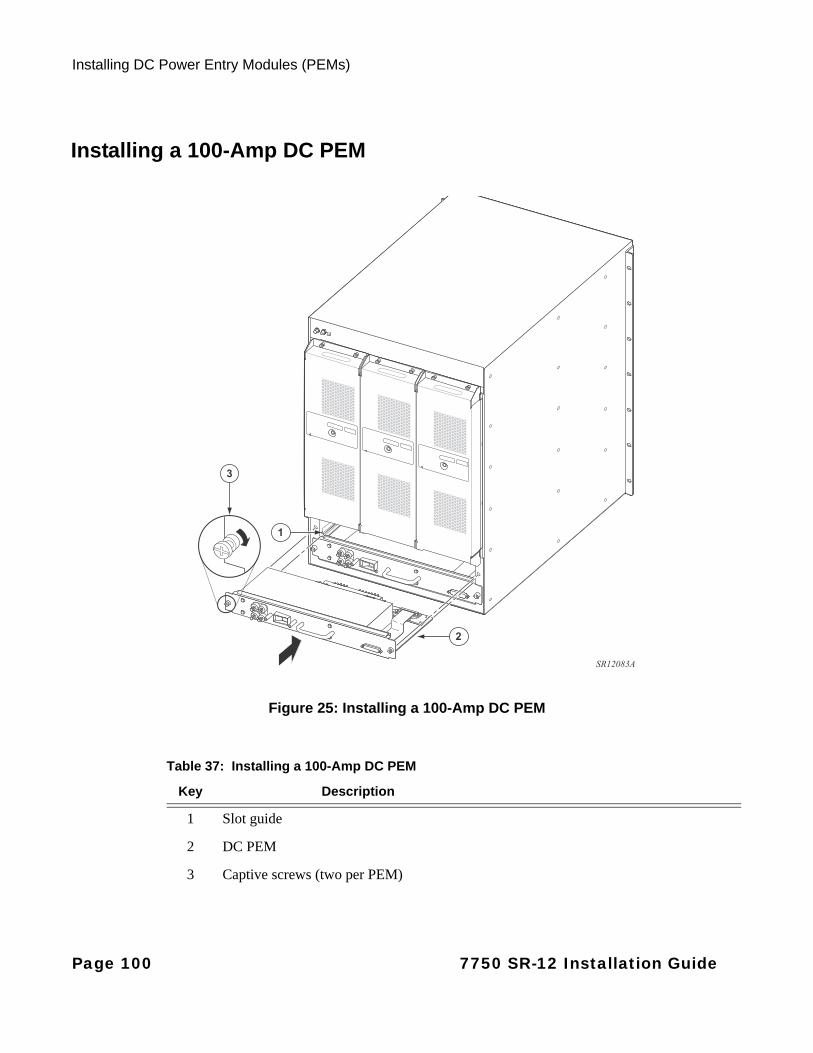
Installing DC Power Entry Modules (PEMs)
Installing a 100-Amp DC PEM
100-Amp DC Pem
Figure 25: Installing a 100-Amp DC PEM
2
3
1
SR12083A
Table 37: Installing a 100-Amp DC PEM
Key Description
1 Slot guide
2 DC PEM
3 Captive screws (two per PEM)
Page 100 7750 SR-12 Installation Guide
Installing Power Supplies
To install a 100-Amp DC PEM:
Step 1 Remove the 100-Amp DC PEM from the packaging.
Step 2 Make sure that the circuit breaker (ON/OFF) on the PEM is in the OFF ( O ) position.
Step 3 Align a 100-Amp DC PEM with a slot guide (either the left or right slot). Slide the unit into the slot until the connectors are fully seated with the receptacle in the rear of the slot.
Step 4 Secure into place by tightening the captive screws.
Step 5 Install a redundant 100-Amp DC PEM. Align the PEM with the slot guides. Slide the unit into the slot until the connectors are fully seated with the receptacle in the rear of the slot.
Step 6 Secure into place by tightening the captive screws.
Step 7 If you plan to use DC power to operate the 7750 SR-12, proceed to the following steps to connect the power cord(s).
If you plan to install AC power rectifiers to operate the 7750 SR-12, proceed to AC-Input Power Guidelines on page 111.
Step 8 Prepare the power cable terminated only with a UL-listed two-hole lug with 1/4-inch (.635 cm) holes on 3/4-inch (1.905 cm) spacing.
Step 9 Connect the VDC and RTN cables from each DC PEM to separate circuit breakers.
7750 SR-12 Installation Guide Page 101
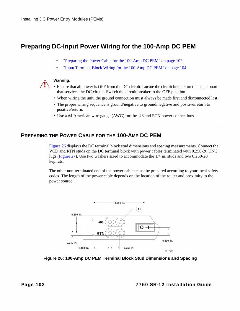
Installing DC Power Entry Modules (PEMs)
Preparing DC-Input Power Wiring for the 100-Amp DC PEM
• "Preparing the Power Cable for the 100-Amp DC PEM" on page 102
• "Input Terminal Block Wiring for the 100-Amp DC PEM" on page 104
PREPARING THE POWER CABLE FOR THE 100-AMP DC PEM
Figure 26 displays the DC terminal block stud dimensions and spacing measurements. Connect the VCD and RTN studs on the DC terminal block with power cables terminated with 0.250-20 UNC lugs (Figure 27). Use two washers sized to accommodate the 1/4 in. studs and two 0.250-20 kepnuts.
The other non-terminated end of the power cables must be prepared according to your local safety codes. The length of the power cable depends on the location of the router and proximity to the power source.
Figure 26: 100-Amp DC PEM Terminal Block Stud Dimensions and Spacing
Warning:
• Ensure that all power is OFF from the DC circuit. Locate the circuit breaker on the panel board that services the DC circuit. Switch the circuit breaker to the OFF position.
• When wiring the unit, the ground connection must always be made first and disconnected last.
• The proper wiring sequence is ground/negative to ground/negative and positive/return to positive/return.
• Use a #4 American wire gauge (AWG) for the -48 and RTN power connections.
SR12032
3.965 IN.
0.850 IN.
0.740 IN.0.600 IN.
1.300 IN. 0.750 IN.
1
Page 102 7750 SR-12 Installation Guide
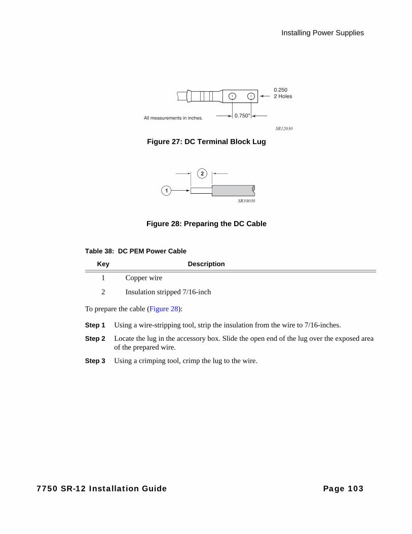
Installing Power Supplies
Figure 27: DC Terminal Block Lug
Figure 28: Preparing the DC Cable
To prepare the cable (Figure 28):
Step 1 Using a wire-stripping tool, strip the insulation from the wire to 7/16-inches.
Step 2 Locate the lug in the accessory box. Slide the open end of the lug over the exposed area of the prepared wire.
Step 3 Using a crimping tool, crimp the lug to the wire.
0.750"
0.2502 Holes
All measurements in inches.
SR12030
1
2
SR10030
Table 38: DC PEM Power Cable
Key Description
1 Copper wire
2 Insulation stripped 7/16-inch
7750 SR-12 Installation Guide Page 103

Installing DC Power Entry Modules (PEMs)
INPUT TERMINAL BLOCK WIRING FOR THE 100-AMP DC PEM
For the 100-Amp DC PEM, the power supply cables attach to the power supply terminal studs. Figure 29, Figure 30, and Figure 31 display DC-input terminal block safety cover and wiring views.
Figure 29: Removing the 100-Amp DC PEM Terminal Block Safety Cover
Figure 30: Wiring the 100-Amp DC PEM Input Power Terminal Block
SR12016
1
2
SR12017
Page 104 7750 SR-12 Installation Guide
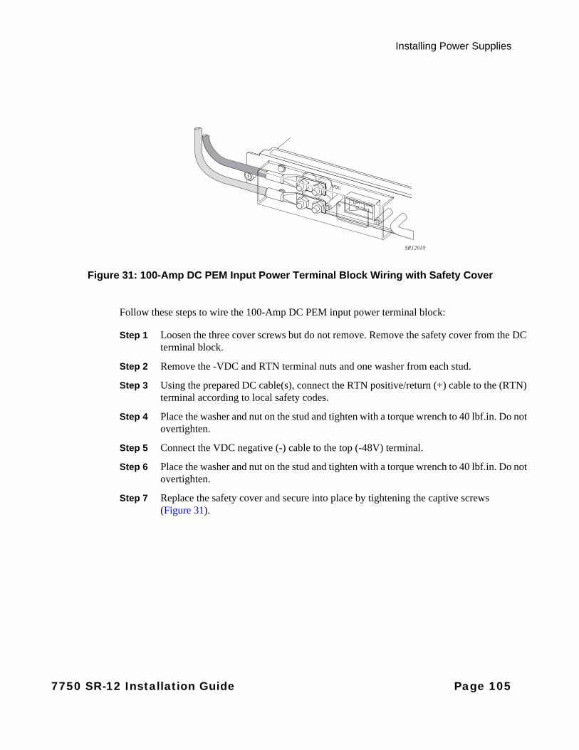
Installing Power Supplies
Figure 31: 100-Amp DC PEM Input Power Terminal Block Wiring with Safety Cover
Follow these steps to wire the 100-Amp DC PEM input power terminal block:
Step 1 Loosen the three cover screws but do not remove. Remove the safety cover from the DC terminal block.
Step 2 Remove the -VDC and RTN terminal nuts and one washer from each stud.
Step 3 Using the prepared DC cable(s), connect the RTN positive/return (+) cable to the (RTN) terminal according to local safety codes.
Step 4 Place the washer and nut on the stud and tighten with a torque wrench to 40 lbf.in. Do not overtighten.
Step 5 Connect the VDC negative (-) cable to the top (-48V) terminal.
Step 6 Place the washer and nut on the stud and tighten with a torque wrench to 40 lbf.in. Do not overtighten.
Step 7 Replace the safety cover and secure into place by tightening the captive screws (Figure 31).
SR12018
7750 SR-12 Installation Guide Page 105
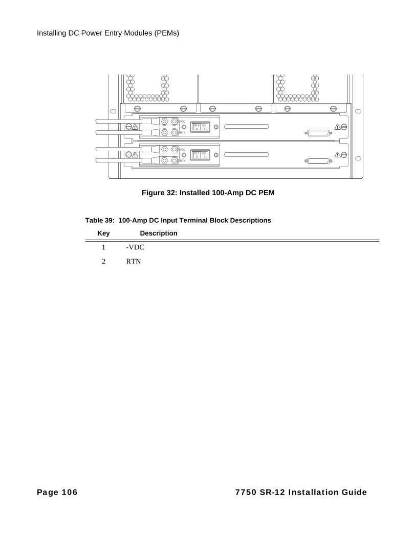
Installing DC Power Entry Modules (PEMs)
Figure 32: Installed 100-Amp DC PEM
VDC
RTN
VDC
RTN
OFFO
ONI
OFFO
ONI
Table 39: 100-Amp DC Input Terminal Block Descriptions
Key Description
1 -VDC
2 RTN
Page 106 7750 SR-12 Installation Guide

Installing Power Supplies
Cabling Considerations
The 7750 SR-12 PEM-3 deploys a single circuit breaker using two sets of physical studs for accommodating up to two cables and lugs. The VDC negative (-) stud pairs are mounted on a single metal plate and are electrically joined. The return (+) stud pairs are also mounted on a single metal plate and are electrically joined. This provides flexibility for provisioning power and associated cabling. Either one or both sets of studs can be used to feed the input.
The 7750 SR-12 routers have a current rating that supports a range from 90 amps up to 162 amps. Typically you will use 4/0 cable to connect your 7750 SR-12 to the branch circuit. Terminating 4/0 cable directly to the feeds on the PEM-3 is problematic due to the thickness and bend radius limitations of the cable. Therefore, Alcatel-Lucent recommends one of the following methods to configure your cables:
• Using H-Taps to Connect Your Power Cables on page 108
• Using a Power Distribution Unit (PDU) to Connect Your Power Cables on page 109
Each of the above methods enables you to use 4/0-gauge cable at the branch circuit and #2 AWG cables to connect to the PEMs.
Make sure to adhere to all local and national safety standards and the warnings described in General Power Warnings and Notes on page 86 when cabling your power system.
7750 SR-12 Installation Guide Page 107

Installing DC Power Entry Modules (PEMs)
USING H-TAPS TO CONNECT YOUR POWER CABLES
Figure 33: Using an H-Tap to Connect Your Power Cables
You can use H-taps to connect your power cables from the branch circuit to your 7750 SR-12 power system. See Figure 33 and follow these steps to connect your power cables using H-taps:
Step 1 At the branch circuit (key 1), connect your four 4/0 cables (key 2).
Step 2 Attach two H-taps (key 3) to each of the 4/0 cables.
Step 3 Connect one #2 AWG cable to each H-tap.
Step 4 Connect each pair of #2 AWG cables (key 4) to the feeds on the PEMs (key 5) as follows:
Connect one pair of #2 AWG cables to the two VDC negative (-) feeds on the top PEM and one pair of #2 AWG cables to the two VDC negative (-) feeds on the bottom PEM. Connect one pair of #2 AWG cables to the two return (+) feeds on the top PEM and one pair of #2 AWG cables to the two return feeds on the bottom PEM.
3
4
1
1
2
2 2
2
5
SR12084A
Page 108 7750 SR-12 Installation Guide
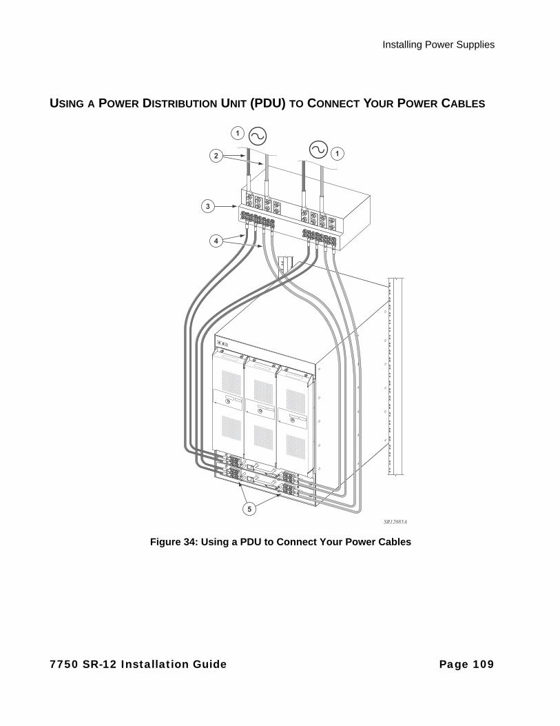
Installing Power Supplies
USING A POWER DISTRIBUTION UNIT (PDU) TO CONNECT YOUR POWER CABLES
Figure 34: Using a PDU to Connect Your Power Cables
4
1
12
3
5
SR12085A
7750 SR-12 Installation Guide Page 109
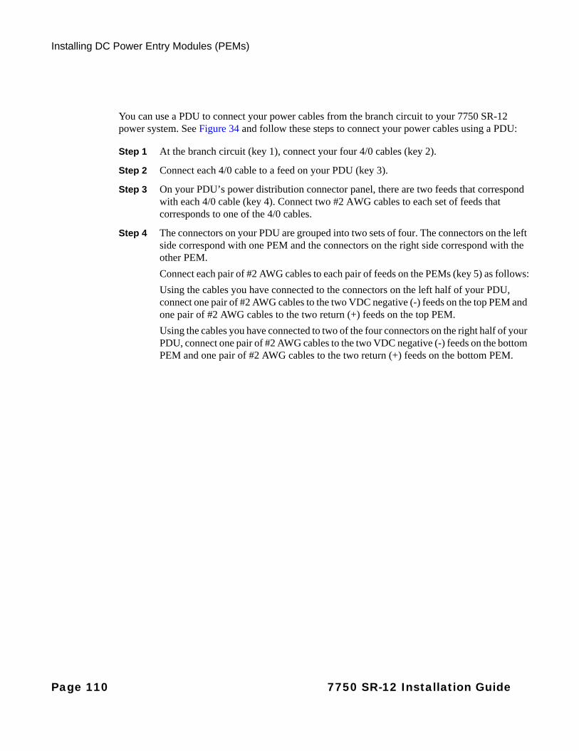
Installing DC Power Entry Modules (PEMs)
You can use a PDU to connect your power cables from the branch circuit to your 7750 SR-12 power system. See Figure 34 and follow these steps to connect your power cables using a PDU:
Step 1 At the branch circuit (key 1), connect your four 4/0 cables (key 2).
Step 2 Connect each 4/0 cable to a feed on your PDU (key 3).
Step 3 On your PDU’s power distribution connector panel, there are two feeds that correspond with each 4/0 cable (key 4). Connect two #2 AWG cables to each set of feeds that corresponds to one of the 4/0 cables.
Step 4 The connectors on your PDU are grouped into two sets of four. The connectors on the left side correspond with one PEM and the connectors on the right side correspond with the other PEM.
Connect each pair of #2 AWG cables to each pair of feeds on the PEMs (key 5) as follows:
Using the cables you have connected to the connectors on the left half of your PDU, connect one pair of #2 AWG cables to the two VDC negative (-) feeds on the top PEM and one pair of #2 AWG cables to the two return (+) feeds on the top PEM.
Using the cables you have connected to two of the four connectors on the right half of your PDU, connect one pair of #2 AWG cables to the two VDC negative (-) feeds on the bottom PEM and one pair of #2 AWG cables to the two return (+) feeds on the bottom PEM.
175-Amp DC PEM-3
Page 110 7750 SR-12 Installation Guide

Installing Power Supplies
AC-Input Power Guidelines
This section provides information and instructions to perform the following:
• AC Power Warnings and Notes on page 111
• Installing an AC Power Shelf on page 113
• Installing the AC Power Rectifiers on page 113
• Connecting The AC Power Shelf Cables to the DC PEMs on page 114
AC
AC Power Warnings and Notes
Caution:
• Follow the manufacturer’s instructions to install AC power shelves.
• The 7750 SR-12 must be directly connected to the DC power supply system earthing electrode conductor or to a bonding jumper from an earthing terminal bar or bus to which the DC power supply system earthing electrode is connected.
• The AC power source and rectifiers that supply DC power must be located within the same premises as this equipment.
• There must be no switching or disconnecting devices in the earthed circuit conductor between the DC source and the point of connection of the earthing electrode conductor.
Warning:
• Before connecting or disconnecting ground or power wires to the AC power shelf and rectifiers, make sure that power is removed from the AC circuit.
7750 SR-12 Installation Guide Page 111

AC-Input Power Guidelines
If you intend to use AC power rectifiers to convert AC power, observe the following guidelines:
• There are no AC power cord receptacles on the 7750 SR-12 chassis. AC power must be converted to usable DC input power by connecting an external rectifier to the terminal studs on the PEM(s).
• External AC rectifiers must be able to operate with a nominal utility system voltage of 150V to 240V, or operate with input voltages ranging from 200 to 240 VAC.
• The number of AC power shelves and rectifiers depend on your configuration of IOMs and MDAs, as the cumulative power requirements can vary.
• Make sure all your cables conform to local safety codes.
• Each AC power shelf is connected directly to a DC PEM. Status is supplied through a DB-25 connection from an AC power shelf to a DC PEM.
• You must connect a grounding cable to provide a ground connection from the power shelf to the equipment rack and the 7750 SR-12 router.
For a listing of the electrical specifications for the AC-input power supply, see "Power Module Specifications" on page 41.
Notes:
• The remote power source (circuit breaker panel, outlet, etc.) must be easily accessible.
• AC power shelves and rectifiers can be ordered from Alcatel-Lucent.
• Use the cables supplied with the rectifiers. The AC power cable is non-terminated on the wall AC power-source end of the cable and must be prepared according to your local safety codes (see Figure 35 on page 114). Plugs are not provided.
• If the 7750 SR-12 router is located in the United States and cables are misplaced or lost, at the minimum use #4 American wire gauge (AWG) for the -48 and RTN power connections. Consult your local and national electrical codes to calculate the appropriate cable sizing.
• Consult your power engineering personnel to calculate the required amperage of your power cable. The cable must be able to provide power for a fully loaded 7750 SR-12 system input per NEC and local safety codes.
• For full redundancy, each power supply module should be attached to an independent power source with a dedicated circuit breaker.
Page 112 7750 SR-12 Installation Guide

Installing Power Supplies
Installing an AC Power Shelf
The AC power shelf converts AC power from an external AC power source into DC power that is suitable for the 7750 SR-12 router. On systems using the PEM-3, a 1:1 power shelf to PEM-3 ratio exists with a maximum of two shelves and two PEMs per chassis. On systems using the PEM, a 1:2 power shelf to PEM ratio exists with one shelf and two PEMs per chassis.
If you install a power shelf that was not provided by Alcatel-Lucent, follow the manufacturer’s instructions to install AC power shelves. See Figure 35 on page 114 for an example of the installation.
AC input power, DC output power, and status are provided with cable connections from the rear of the power shelf. Individual power cables connect each AC power rectifier to the AC input power source. Each AC power shelf has DC-interconnect cables to provide DC output power (-48 DC) to the DC PEMs.
An internal fan in each rectifier circulates air from the front of the shelf, through the power module, and out through rear vents.
Installing the AC Power Rectifiers
NOTE: For normal operation, the 7750 SR-12 requires four rectifiers in an AC power shelf. Four rectifiers equally power share the load. If a rectifier fails or if power is removed to a unit, the other rectifiers power share the full load and maintain continuous system operation.
Caution: A single AC power rectifier weighs approximately 6 lbs. (2.7 kg). Use both hands when installing a rectifier.
Notes: Follow the manufacturer’s instructions to install AC power rectifiers.
7750 SR-12 Installation Guide Page 113
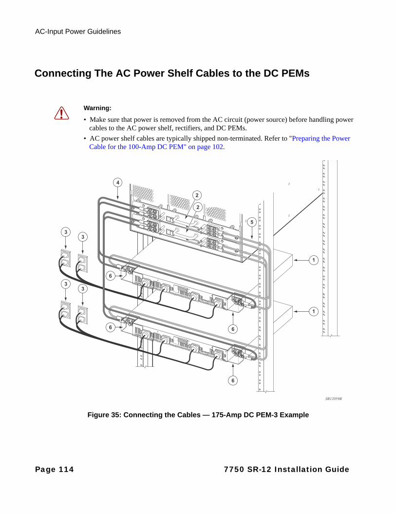
AC-Input Power Guidelines
Connecting The AC Power Shelf Cables to the DC PEMs
Figure 35: Connecting the Cables — 175-Amp DC PEM-3 Example
Warning:
• Make sure that power is removed from the AC circuit (power source) before handling power cables to the AC power shelf, rectifiers, and DC PEMs.
• AC power shelf cables are typically shipped non-terminated. Refer to "Preparing the Power Cable for the 100-Amp DC PEM" on page 102.
5
2
2
4
3
3
3
3
1
1
SR12059B
6
6
6
6
Page 114 7750 SR-12 Installation Guide
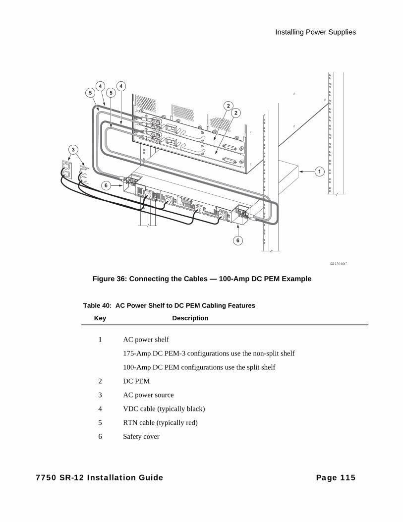
Installing Power Supplies
Figure 36: Connecting the Cables — 100-Amp DC PEM Example
45
45
22
3
1
6
SR12010C
6
Table 40: AC Power Shelf to DC PEM Cabling Features
Key Description
1 AC power shelf
175-Amp DC PEM-3 configurations use the non-split shelf
100-Amp DC PEM configurations use the split shelf
2 DC PEM
3 AC power source
4 VDC cable (typically black)
5 RTN cable (typically red)
6 Safety cover
7750 SR-12 Installation Guide Page 115

AC-Input Power Guidelines
Connect the power cables after the DC PEMs, AC power shelves and rectifiers are installed:
Step 1 Prepare the power cables. See Preparing the Power Cable for the 175-Amp DC PEM-3 on page 94 or Preparing the Power Cable for the 100-Amp DC PEM on page 102.
Step 2 Remove the safety cover from the DC terminal block.
Step 3 Loosen the -VDC and RTN terminal nuts (See Figure 37 for the PEM-3 and Figure 38 for the PEM).
Step 4 Using the prepared cable(s), connect the RTN positive/return (+) cable to the (RTN) terminal according to local safety codes.
Step 5 Replace the nuts and tighten with a torque wrench to 40 lbf.in.
Step 6 Connect the VDC cable to the top (-48V) terminal according to local safety codes.
Step 7 Replace the nuts and tighten with a torque wrench to 40 lbf.in.
Step 8 Replace the safety cover.
Figure 37: 175-Amp DC PEM-3 Terminal Block
Figure 38: 100-Amp DC PEM Terminal Block
21
21SR12060
VDC
RTN
OFFO
ONI
1
2
SR12019
Page 116 7750 SR-12 Installation Guide
Installing Power Supplies
Step 9 Plug the other end of the AC input power cables into the AC power source.
Step 10 Check the LEDs on each rectifier.
Step 11 Set the power switch on each DC PEM to the ON position ( | ).
Step 12 Proceed to the next section for instructions to install the SF/CPM(s). Perform the card slot, card type, MDA, and port preconfigurations prior to installing the IOMs and MDAs. See "Installing the SF/CPM" on page 121 for instructions.
7750 SR-12 Installation Guide Page 117
Monitoring AC Power
Monitoring AC Power
You can attach a power supply monitoring (Y-type) cable from the J10 and J11 connectors on the rear of the AC power shelf to a DB-25 connector on the DC PEM. The connection provides status such as AC power supply presence, fault reporting, and over-temperature conditions to the active CPM and lights the corresponding power supply LEDs on the CPM faceplate.
If you are using an unsplit shelf with four rectifiers, two cables will be required, one for each PEM. If you are using a split shelf with two rectifiers and one PEM, only one cable is required.
The following are the optically isolated open-collector signals:
• Fault — The unit has detected an internal fault.
• Overtemperature Warning (OTW) — The unit is overheating. Shutdown is imminent (8- second warning).
• Power Fail Warning — The output of the power unit will fail within five milliseconds.
See "Appendix C: Pinout Assignments" on page 201 for the status cable pin assignments.
Page 118 7750 SR-12 Installation Guide
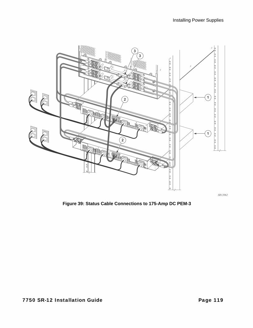
Installing Power Supplies
Figure 39: Status Cable Connections to 175-Amp DC PEM-3
2
33
2
1
1
SR12062
7750 SR-12 Installation Guide Page 119
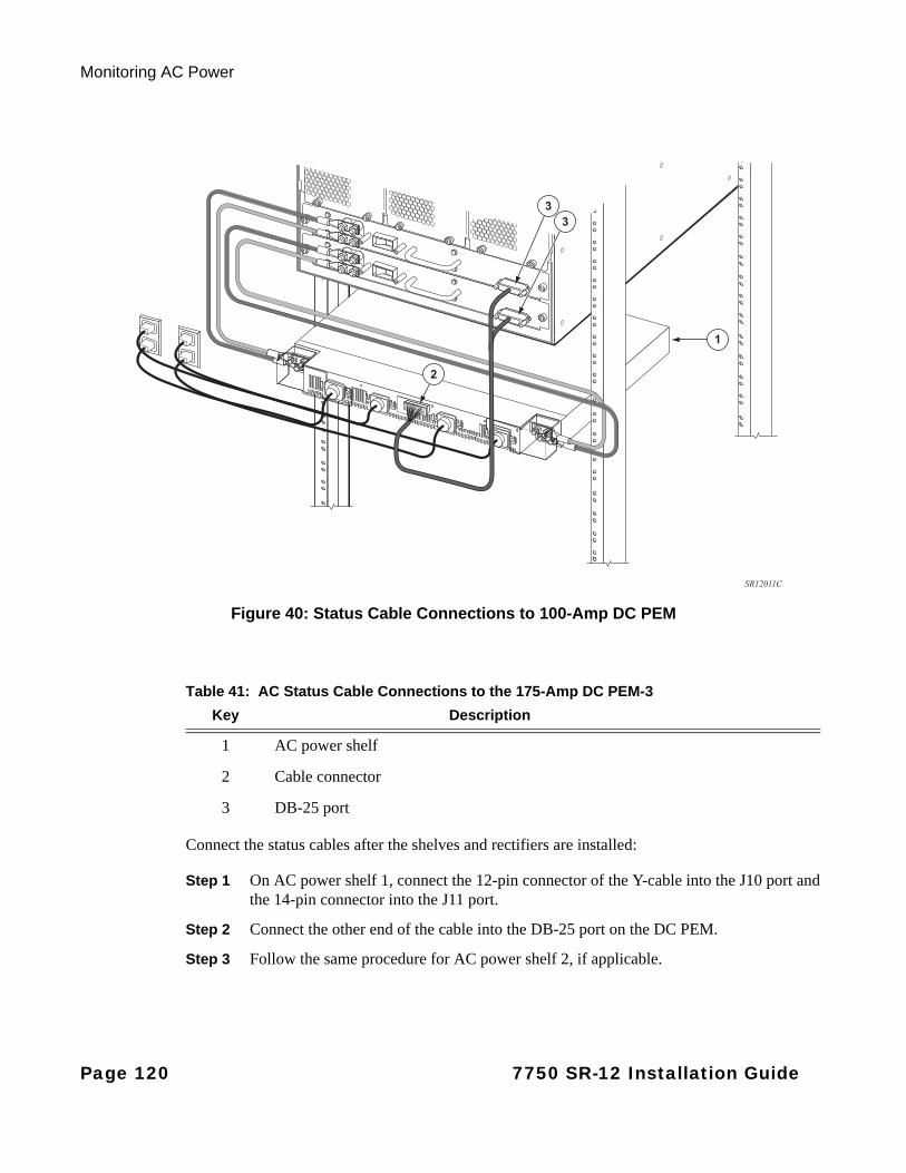
Monitoring AC Power
Figure 40: Status Cable Connections to 100-Amp DC PEM
Connect the status cables after the shelves and rectifiers are installed:
Step 1 On AC power shelf 1, connect the 12-pin connector of the Y-cable into the J10 port and the 14-pin connector into the J11 port.
Step 2 Connect the other end of the cable into the DB-25 port on the DC PEM.
Step 3 Follow the same procedure for AC power shelf 2, if applicable.
2
33
1
SR12011C
Table 41: AC Status Cable Connections to the 175-Amp DC PEM-3
Key Description
1 AC power shelf
2 Cable connector
3 DB-25 port
Page 120 7750 SR-12 Installation Guide
Installing the SF/CPM
In This Chapter
This chapter provides information about installing the SF/CPM, router connections, image, and preconfiguration information.
This chapter provides information on the following topics:
• Installing SF/CPM Modules on page 122
• Initializing the System on page 125
• Initial System Startup on page 127
• Establishing Router Connections on page 130
7750 SR-12 Installation Guide Page 121

Installing SF/CPM Modules
Installing SF/CPM Modules
Warnings and Notes
Warning:
• Electrostatic discharge (ESD) damage can occur if IOMs, SF/CPMs, or MDAs are mishandled. Always wear an ESD-preventive wrist or ankle strap and always connect an ESD strap to the grounding plug on the front of the chassis.
• Always place router components on an anti-static surface.
• Do not power up the 7750 SR-12 until all components are installed and verified.
• Impedance panels are required in all empty card and component slots to prevent excess dust accumulation and to help control airflow and electromagnetic interference. Faceplate blanks do not have board components or connector pins.
Notes:
General:• SF/CPM modules do not require preconfiguration. Factory default values enable the system to
boot successfully.
• The 7750 SR-12 router requires at least one SF/CPM.
• Install the SF/CPM before installing any IOMs.
• Do not force an IOM into a SF/CPM slot.
• Do not force a SF/CPM into an IOM slot.
7750 SR-12:• The SR-12 card slots are vertically oriented.
• In the SR-12, SF/CPMs must be installed in the center slots labeled A and B.
• IOMs are designed to fit in slots numbered from left to right, 1 through 10.
Page 122 7750 SR-12 Installation Guide
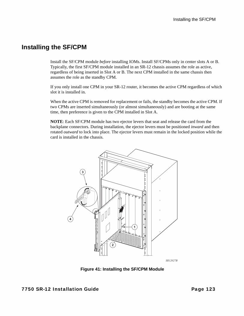
Installing the SF/CPM
Installing the SF/CPM
Install the SF/CPM module before installing IOMs. Install SF/CPMs only in center slots A or B. Typically, the first SF/CPM module installed in an SR-12 chassis assumes the role as active, regardless of being inserted in Slot A or B. The next CPM installed in the same chassis then assumes the role as the standby CPM.
If you only install one CPM in your SR-12 router, it becomes the active CPM regardless of which slot it is installed in.
When the active CPM is removed for replacement or fails, the standby becomes the active CPM. If two CPMs are inserted simultaneously (or almost simultaneously) and are booting at the same time, then preference is given to the CPM installed in Slot A.
NOTE: Each SF/CPM module has two ejector levers that seat and release the card from the backplane connectors. During installation, the ejector levers must be positioned inward and then rotated outward to lock into place. The ejector levers must remain in the locked position while the card is installed in the chassis.
Figure 41: Installing the SF/CPM Module
2
1
SR12027B
4
3
7750 SR-12 Installation Guide Page 123
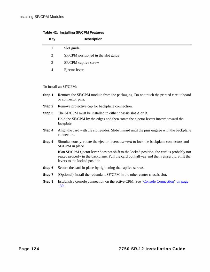
Installing SF/CPM Modules
To install an SF/CPM:
Step 1 Remove the SF/CPM module from the packaging. Do not touch the printed circuit board or connector pins.
Step 2 Remove protective cap for backplane connection.
Step 3 The SF/CPM must be installed in either chassis slot A or B.
Hold the SF/CPM by the edges and then rotate the ejector levers inward toward the faceplate.
Step 4 Align the card with the slot guides. Slide inward until the pins engage with the backplane connectors.
Step 5 Simultaneously, rotate the ejector levers outward to lock the backplane connectors and SF/CPM in place.
If an SF/CPM ejector lever does not shift to the locked position, the card is probably not seated properly in the backplane. Pull the card out halfway and then reinsert it. Shift the levers to the locked position.
Step 6 Secure the card in place by tightening the captive screws.
Step 7 (Optional) Install the redundant SF/CPM in the other center chassis slot.
Step 8 Establish a console connection on the active CPM. See "Console Connection" on page 130.
Table 42: Installing SF/CPM Features
Key Description
1 Slot guide
2 SF/CPM positioned in the slot guide
3 SF/CPM captive screw
4 Ejector lever
Page 124 7750 SR-12 Installation Guide
Installing the SF/CPM
Initializing the System
The primary copy of 7750 SR OS software is located on a compact flash card that must be installed in Compact Flash Slot #3 (cf3:) in the active CPM. The removable media shipped with each software license contains a copy of the 7750 SR OS software.
Notes:
• The SF/CPM modules contain three slots for removable compact flash cards. The drives are named Compact Flash Slot #1 (cf1:), Compact Flash Slot #2 (cf2:), and Compact Flash Slot #3 (cf3:). Configurations and executable images can be stored on flash cards or an FTP file location.
• The flash card containing the bootstrap and boot option files must be installed in Compact Flash Slot #3 (cf3:) on the SF/CPM.
• You must have a console connection. See "Console Connection" on page 130 on the active CPM.
7750 SR-12 Installation Guide Page 125
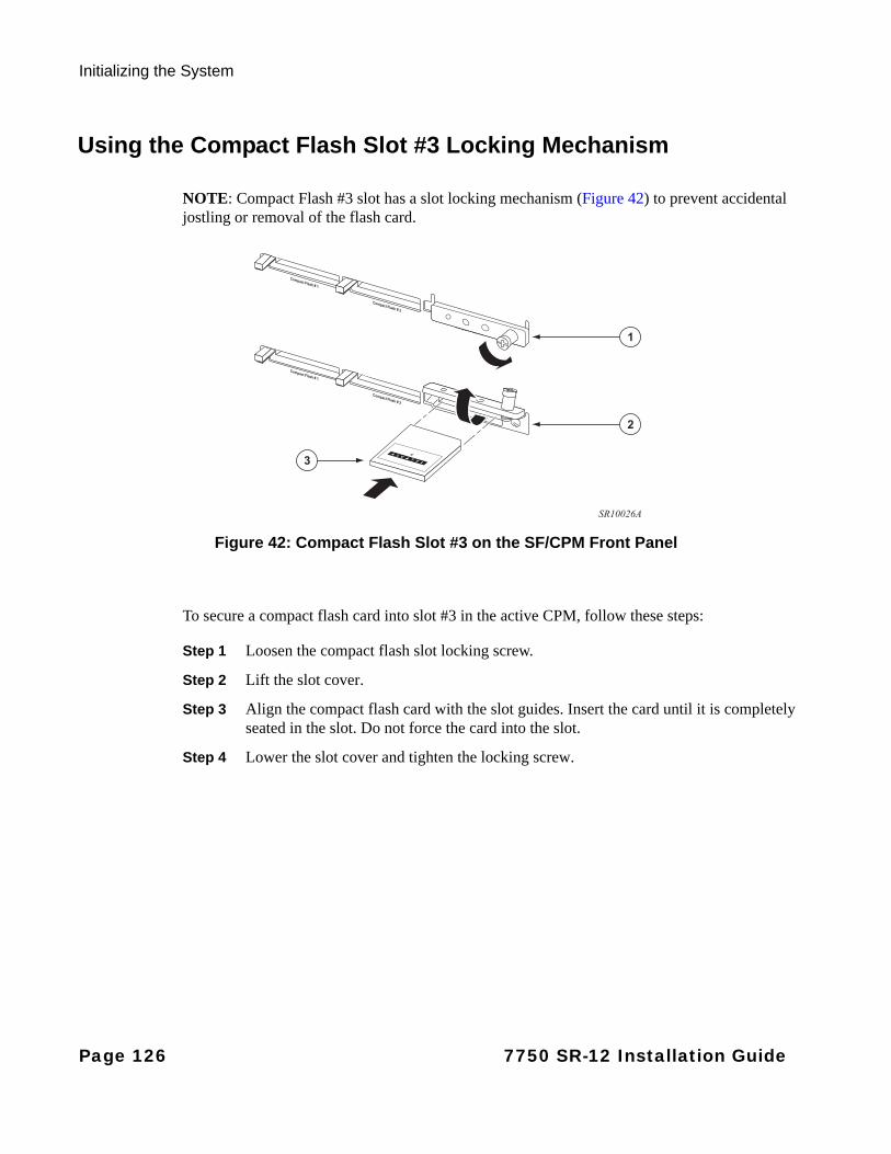
Initializing the System
Using the Compact Flash Slot #3 Locking Mechanism
NOTE: Compact Flash #3 slot has a slot locking mechanism (Figure 42) to prevent accidental jostling or removal of the flash card.
Figure 42: Compact Flash Slot #3 on the SF/CPM Front Panel
To secure a compact flash card into slot #3 in the active CPM, follow these steps:
Step 1 Loosen the compact flash slot locking screw.
Step 2 Lift the slot cover.
Step 3 Align the compact flash card with the slot guides. Insert the card until it is completely seated in the slot. Do not force the card into the slot.
Step 4 Lower the slot cover and tighten the locking screw.
3
1
2
SR10026A
Page 126 7750 SR-12 Installation Guide
Installing the SF/CPM
Initial System Startup
To initialize the system, follow these steps:
Step 1 When the compact flash card is installed in the cf3: slot, the Compact Flash 3 LED on the active CPM front panel should light green within approximately 30 seconds. If it does not light or if it turns off, see "Troubleshooting".
Step 2 Press the Reset button on the active CPM or power cycle the router to initiate the boot process.
Step 3 The system searches cf3: for the boot.ldr file (also known as the bootstrap file).
Step 4 Verify the operational status by checking the Power and Status LEDs on the active CPM faceplate. If the LEDs on the front panel blink continuously, refer to "Troubleshooting" on page 127.
Step 5 After verifying the LEDs, proceed with the IOM and MDA installation and configurations.
You can either preconfigure the IOMs, MDAs, and ports prior to installation or install the IOMs and MDAs first and then configure the parameters.
To preconfigure IOMs and MDAs, see "Configuring Chassis Slot and IOM Parameters" on page 136.
TROUBLESHOOTING
If the Compact Flash 3 LED does not light after 30 seconds, the compact flash card is probably faulty. If the system cannot load or cannot find the boot.ldr file on cf3:, the Compact Flash 3 LED will turn off and the system will check for a manual boot sequence interruption. A manual boot sequence interruption is performed by connecting a terminal to a console port and hitting any key when prompted by the display. Unless an unsuccessful system initialization is manually interrupted, the system will continuously reboot in an attempt to successfully find and load the boot.ldr file. Load a compact flash card with the appropriate boot.ldr file into the cf3: slot.
When the system finds the boot.ldr file, the system processes the initialization parameters from the BOF (boot option file). The BOF should be on the same drive as the boot loader file. If the BOF cannot be found or loaded, then the system prompts for a different image and configuration location.
When the image is successfully loaded, control is passed from the boot loader file to the image. The runtime image attempts to locate the configuration file as configured in the BOF. The configuration file include chassis, IOM, MDA, and port configurations, as well as system, routing, and service configurations.
7750 SR-12 Installation Guide Page 127

Initial System Startup
The following example displays the output when either no flash is present or the boot.ldr file cannot be found.
. . .
Alcatel 7750 SRBuild: X-0.0.x.x on Thu Apr 06 21:05:50 2006 by builderStarting CPU/Switch cardCOLD boot on processor #1CPU Control FPGA version is 0x17Testing mainboard FPGA chain...Validating SDRAM from 0x7ff00000 to 0x80000000Testing SDRAM from 0x02200000 to 0x7ff00000Testing Compact Flash 1... Slot EmptyTesting Compact Flash 2... Slot EmptyTesting Compact Flash 3... Slot EmptyPeripheral FPGA version is 0x13Board Serial Number is 'rus4-07'Chassis Serial Number is '0103010009'Searching for boot.ldr on local drives:No disk in cf3No disk in cf3No disk in cf3Error - file boot.ldr not found on any drivePlease insert CF containing boot.ldr. Rebooting in 5 seconds.
Rebooting...
AlcatelBuild: X-0.0.x.x on Thu Apr 06 21:05:50 2006 by builderStarting CPU/Switch card
It is important that cables connected to the console port on the 7xx0 SR/ESS/MG products are properly terminated so as to not negatively affect the functioning of the node. Terminal servers should be properly configured so that unwanted signals from the connected device do not launch.
Noisy lines can be interpreted by the node as key strokes and could interrupt the boot sequence resulting in an outage. After reboot, the CPM can go into a continuous reboot cycle if the boot process is interrupted by random characters received on the console port.
To prevent this from happening, terminate all console connections. If a terminal server is connected to the 7xx0 CPM/CFM then ensure that it is configured to not send unwanted characters to the CPM/CFM that could interrupt the boot cycle. This could be done by configuring a 'no exec' or equivalent CLI command on the terminal server.
Page 128 7750 SR-12 Installation Guide
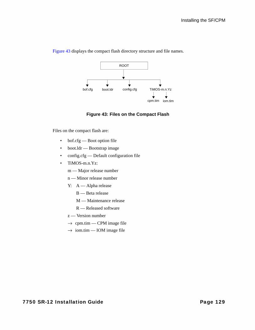
Installing the SF/CPM
Figure 43 displays the compact flash directory structure and file names.
Figure 43: Files on the Compact Flash
Files on the compact flash are:
• bof.cfg — Boot option file
• boot.ldr — Bootstrap image
• config.cfg — Default configuration file
• TiMOS-m.n.Yz:
m — Major release number
n — Minor release number
Y: A — Alpha release
B — Beta release
M — Maintenance release
R — Released software
z — Version number
→ cpm.tim — CPM image file
→ iom.tim — IOM image file
ROOT
bof.cfg boot.ldr config.cfg TiMOS-m.n.Yz
cpm.tim iom.tim
7750 SR-12 Installation Guide Page 129
Establishing Router Connections
Establishing Router Connections
Access your newly installed router two ways:
• Console Connection on page 130
• Telnet Connection on page 132
Console Connection
To establish a console connection, you will need the following:
• An ASCII terminal or a PC running terminal emulation software set to the parameters shown in the table below.
• A standard serial cable with a female DB-9 connector.
See Table 43 for the console configuration parameter values. See Figure 44 for the locationof the console connection.
For pinout information, refer to "Appendix C: Pinout Assignments" on page 201.
Table 43: Console Configuration Parameter Values
Parameter Value
Baud Rate 115,200
Data Bits 8
Parity None
Stop Bits 1
Flow Control None
Page 130 7750 SR-12 Installation Guide
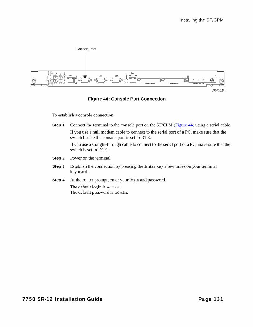
Installing the SF/CPM
Figure 44: Console Port Connection
To establish a console connection:
Step 1 Connect the terminal to the console port on the SF/CPM (Figure 44) using a serial cable.
If you use a null modem cable to connect to the serial port of a PC, make sure that the switch beside the console port is set to DTE.
If you use a straight-through cable to connect to the serial port of a PC, make sure that the switch is set to DCE.
Step 2 Power on the terminal.
Step 3 Establish the connection by pressing the Enter key a few times on your terminal keyboard.
Step 4 At the router prompt, enter your login and password.
The default login is admin.The default password is admin.
SR40028
Console Port
7750 SR-12 Installation Guide Page 131

Establishing Router Connections
Telnet Connection
Access the router after a successful initialization with a Telnet connection from a PC or workstation connected to the network after the management port (Figure 45) has been configured using the bof>address command (see below). Telnet access provides the same options for user and administrator access as those available through the console port.
To configure the 7750 SR-12 for Telnet access, you need to have a device with Telnet software located on the same network. The SR-12 must have a management IP address. The IP address is manually configured. Each 7750 SR router is limited to a total of 7 inbound/outbound Telnet or SSH sessions to guarantee that either inbound or outbound sessions will be available. For information about configuring router parameters, refer to the 7750 SR OS Router Configuration Guide. For pinout information, refer to Appendix C: Pinout Assignments on page 201.
MAC addresses are listed on a small label on the chassis, IOM, and MDA. The MAC address also displays in the show router arp command output.
Figure 45: Management Port Connection
CLI Syntax: bof cflash-idaddress ip-addr/mask [primary|secondary]
The SR-12 must have a management IP address. Configure the IP address manually.
SR40028
Mgmt Port
Page 132 7750 SR-12 Installation Guide
Installing the SF/CPM
RUNNING TELNET
Once the IP parameters are configured, the CLI command line can be accessed with a Telnet connection. To establish a Telnet connection, run a Telnet program and issue the Telnet command, followed by the IP address.
The following displays an example of a Telnet login:
C:\>telnet 192.168.1.111Login: adminPassword: ########
SR12#
7750 SR-12 Installation Guide Page 133
Establishing Router Connections
EJECTING FLASH CARDS
To eject the slot #3 flash card:
Step 1 You must enter the shutdown command before you remove a flash card.
Command Example
file shutdown cflash-id file shutdown cf3:
Step 2 Loosen the compact flash slot locking screw.
Step 3 Lift the slot cover.
Step 4 The ejector button for Compact Flash Slot #3 is slightly recessed. Insert a small object such as a pen tip to press the button. The card will partially pop out of the slot.
Step 5 Remove the card and place it in an anti-static bag.
You must install the flash card containing the boot and configuration files in Compact Flash Slot #3 (cf3:) on the SF/CPM card.
Step 6 Lower the slot cover and tighten the locking screw.
To eject the slot #1 or slot #2 flash cards:
Step 1 You must enter the shutdown command before you remove a flash card.
Command Example
file>shutdown cflash-id file shutdown cf1:
file>shutdown cflash-id file shutdown cf2:
Step 2 Press the ejector button on compact flash slot #1 or compact flash slot #2. The card will partially pop out of the slot.
Step 3 Remove the card and place it in an anti-static bag.
Page 134 7750 SR-12 Installation Guide
Installing IOMs, MDAs, and IMMs
In This Chapter
This chapter provides information about installing IOMs, MDAs, and IMMs and contains the following topics:
• Configuring Chassis Slot, IOM, MDA, and IMM Parameters on page 136
• Installing IOMs and IMMs on page 139
• Installing MDAs on page 142
7750 SR-12 Installation Guide Page 135
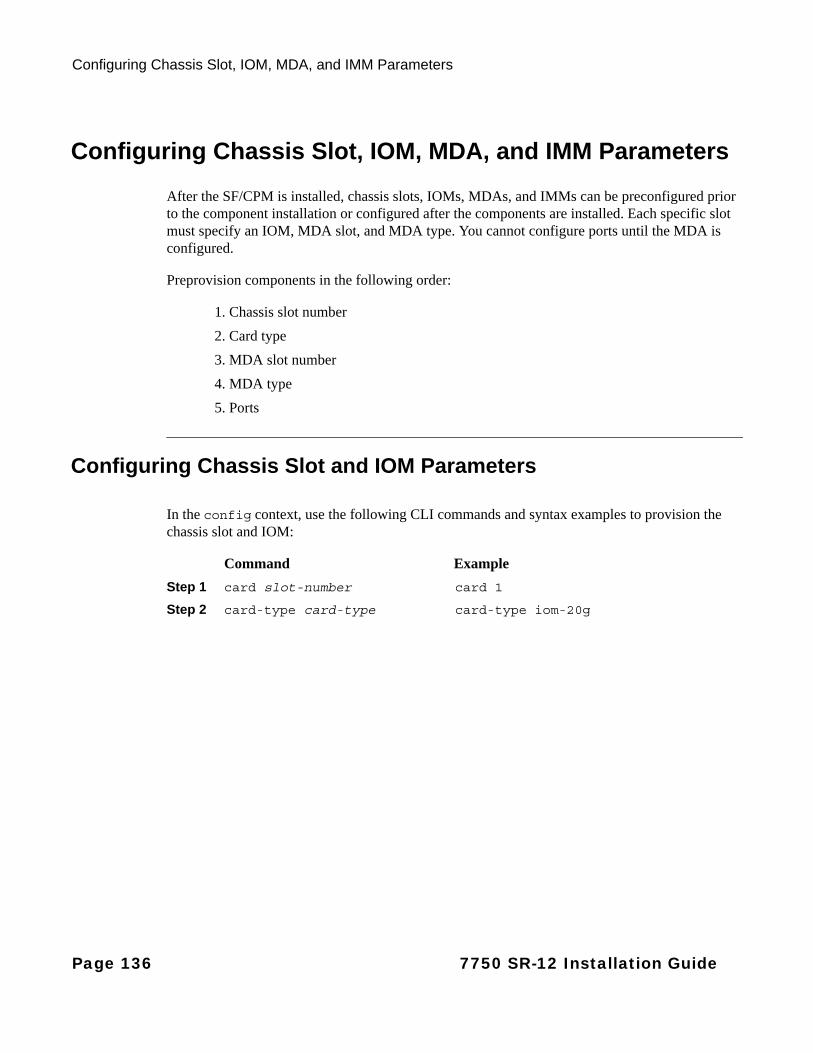
Configuring Chassis Slot, IOM, MDA, and IMM Parameters
Configuring Chassis Slot, IOM, MDA, and IMM Parameters
After the SF/CPM is installed, chassis slots, IOMs, MDAs, and IMMs can be preconfigured prior to the component installation or configured after the components are installed. Each specific slot must specify an IOM, MDA slot, and MDA type. You cannot configure ports until the MDA is configured.
Preprovision components in the following order:
1. Chassis slot number
2. Card type
3. MDA slot number
4. MDA type
5. Ports
Configuring Chassis Slot and IOM Parameters
In the config context, use the following CLI commands and syntax examples to provision the chassis slot and IOM:
Command Example
Step 1 card slot-number card 1
Step 2 card-type card-type card-type iom-20g
Page 136 7750 SR-12 Installation Guide
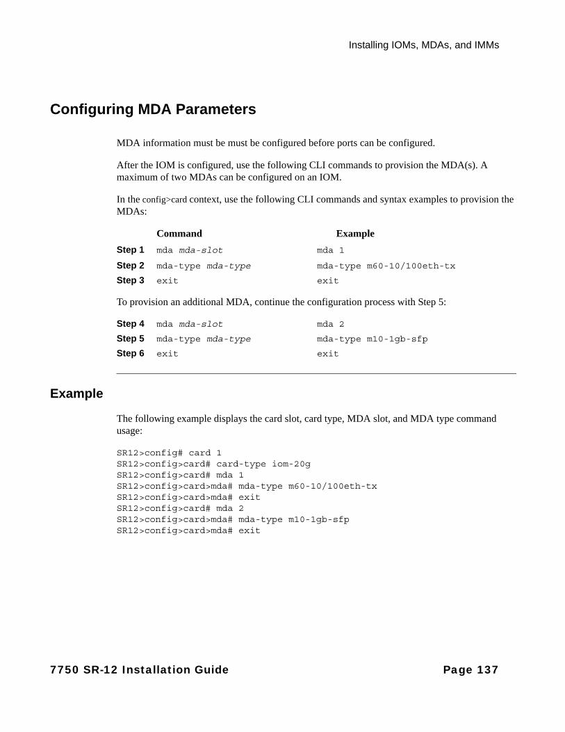
Installing IOMs, MDAs, and IMMs
Configuring MDA Parameters
MDA information must be must be configured before ports can be configured.
After the IOM is configured, use the following CLI commands to provision the MDA(s). A maximum of two MDAs can be configured on an IOM.
In the config>card context, use the following CLI commands and syntax examples to provision the MDAs:
Command Example
Step 1 mda mda-slot mda 1
Step 2 mda-type mda-type mda-type m60-10/100eth-tx
Step 3 exit exit
To provision an additional MDA, continue the configuration process with Step 5:
Step 4 mda mda-slot mda 2
Step 5 mda-type mda-type mda-type m10-1gb-sfp
Step 6 exit exit
Example
The following example displays the card slot, card type, MDA slot, and MDA type command usage:
SR12>config# card 1SR12>config>card# card-type iom-20gSR12>config>card# mda 1SR12>config>card>mda# mda-type m60-10/100eth-tx SR12>config>card>mda# exitSR12>config>card# mda 2SR12>config>card>mda# mda-type m10-1gb-sfp SR12>config>card>mda# exit
7750 SR-12 Installation Guide Page 137

Configuring Chassis Slot, IOM, MDA, and IMM Parameters
The following example displays the configuration:
SR12>config# info. . . ----------------------------------------------echo "Card Configuration "#------------------------------------------
card 1 card-type iom-20g mda 1 mda-type m60-10/100eth-tx exit mda 2 mda-type m10-1gb-sfp exit
exit----------------------------------------------SR12>config#
Configuring IMM Parameters
For information on configuring IMM parameters, refer to the 7750 SR-12 Integrated Media Modules manual.
Page 138 7750 SR-12 Installation Guide
Installing IOMs, MDAs, and IMMs
Installing IOMs and IMMs
Warnings and Notes
Warning:
• Electrostatic discharge (ESD) damage can occur if IOMs, IMMs, SF/CPMs, or MDAs are mishandled. Always wear an ESD-preventive wrist or ankle strap and always connect an ESD strap to the grounding plug on the front of the chassis.
• Always place router components on an anti-static surface.
• Impedance panels are required in all empty card and component slots to prevent excess dust accumulation and to help control airflow and electromagnetic interference. Faceplate blanks do not have board components or connector pins.
Notes:
General:• You can configure card, MDA, and port information before you perform component installation.
• Do not force an IOM or IMM into an SF/CPM slot.
• Do not force a SF/CPM into an IOM slot.
7750 SR-12:
• The 7750 SR-12 card slots are vertically oriented.
• IOMs and IMMs are designed to fit in slots 1 through 10.
7750 SR-12 Installation Guide Page 139
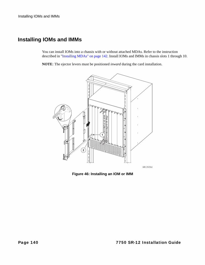
Installing IOMs and IMMs
Installing IOMs and IMMs
You can install IOMs into a chassis with or without attached MDAs. Refer to the instruction described in "Installing MDAs" on page 142. Install IOMs and IMMs in chassis slots 1 through 10.
NOTE: The ejector levers must be positioned inward during the card installation.
Figure 46: Installing an IOM or IMM
2
1
SR12020A
Page 140 7750 SR-12 Installation Guide

Installing IOMs, MDAs, and IMMs
To install an IOM or IMM, see Figure 46 and perform the following steps:
Step 1 Remove the IOM or IMM from the packaging. Do not touch the printed circuit board and connector pins.
Step 2 If the Impedance panel is covering the chassis slot, remove the panel by loosening the panel’s captive screws.
Step 3 Holding the IOM or IMM by the edges, rotate the ejector levers inward. The ejector levers must be in this position to release the locking mechanism.
Step 4 Align the IOM or IMM in the slot guide and slide the IOM inward until the connectors are seated with the backplane.
Step 5 Rotate the ejector levers outward to lock the IOM in place.
If an IOM or IMM lever does not shift to the locked position, the IOM or IMM is not properly seated. Rotate the levers inward and pull the IOM or IMM out halfway and then try to reinsert it. Try again to shift the levers outward to the locked position.
Step 6 Secure the IOM or IMM into place by tightening the captive screws.
7750 SR-12 Installation Guide Page 141
Installing MDAs
Installing MDAs
Warnings and Notes
Warning:
• Electrostatic discharge (ESD) damage can occur if SF/CPMs, IOMs, or MDAs are mishandled. Always wear an ESD-preventive wrist or ankle strap and always connect an ESD strap to the grounding plug on the front of the chassis.
• Invisible laser radiation can be emitted from the aperture ports of an MDA when no cable is connected. Avoid exposure and do not stare into open apertures.
• Always place components on an anti-static surface.
• Do not power up a 7750 SR-12 router until all components are installed and verified.
• Use only approved small form factor pluggables (SFPs) or XFPs (10-Gigabit small form factor pluggables) in MDA ports.
Notes:
General:• Ports cannot be provisioned if the MDA is not preprovisioned.
• Services cannot be provisioned if ports are not provisioned.
• You can install MDAs on an IOM in two ways:
→ Install MDAs on the IOM and then load the unit into the chassis slot. See Installing an MDA on an IOM on page 143.
→ Install MDAs after the IOM is loaded in the chassis slot. See Installing an MDA on a Chassis-Installed IOM on page 145.
• For configuration purposes, MDA slots are numbered 1 (top slot) and 2 (bottom slot).
Page 142 7750 SR-12 Installation Guide
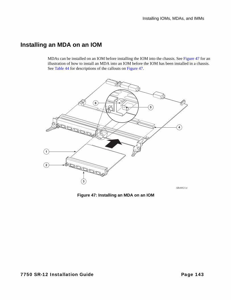
Installing IOMs, MDAs, and IMMs
Installing an MDA on an IOM
MDAs can be installed on an IOM before installing the IOM into the chassis. See Figure 47 for an illustration of how to install an MDA into an IOM before the IOM has been installed in a chassis. See Table 44 for descriptions of the callouts on Figure 47.
Figure 47: Installing an MDA on an IOM
2
1
3
4
SR40021A
5
6
7750 SR-12 Installation Guide Page 143
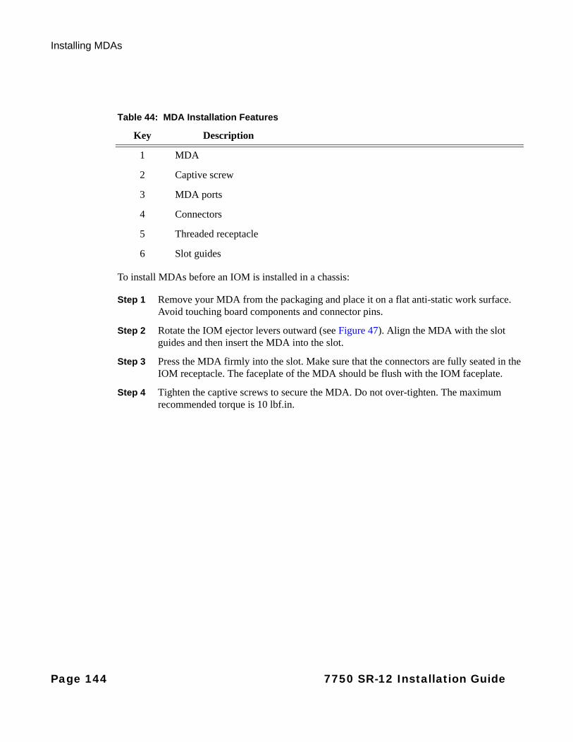
Installing MDAs
To install MDAs before an IOM is installed in a chassis:
Step 1 Remove your MDA from the packaging and place it on a flat anti-static work surface. Avoid touching board components and connector pins.
Step 2 Rotate the IOM ejector levers outward (see Figure 47). Align the MDA with the slot guides and then insert the MDA into the slot.
Step 3 Press the MDA firmly into the slot. Make sure that the connectors are fully seated in the IOM receptacle. The faceplate of the MDA should be flush with the IOM faceplate.
Step 4 Tighten the captive screws to secure the MDA. Do not over-tighten. The maximum recommended torque is 10 lbf.in.
Table 44: MDA Installation Features
Key Description
1 MDA
2 Captive screw
3 MDA ports
4 Connectors
5 Threaded receptacle
6 Slot guides
Page 144 7750 SR-12 Installation Guide
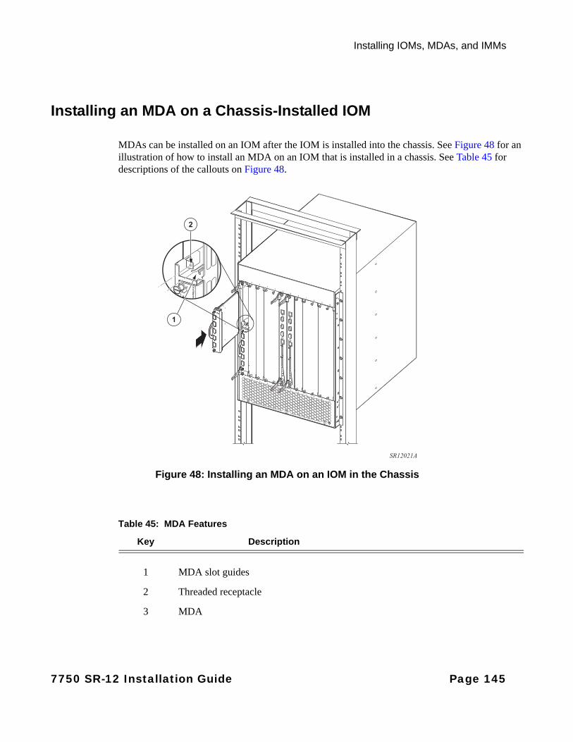
Installing IOMs, MDAs, and IMMs
Installing an MDA on a Chassis-Installed IOM
MDAs can be installed on an IOM after the IOM is installed into the chassis. See Figure 48 for an illustration of how to install an MDA on an IOM that is installed in a chassis. See Table 45 for descriptions of the callouts on Figure 48.
Figure 48: Installing an MDA on an IOM in the Chassis
1
2
SR12021A
Table 45: MDA Features
Key Description
1 MDA slot guides
2 Threaded receptacle
3 MDA
7750 SR-12 Installation Guide Page 145
Installing MDAs
To install an MDA on a chassis-installed IOM:
Step 1 Install the IOM first. See "Installing IOMs and IMMs" on page 139.
Step 2 Remove the MDA from the packaging. Avoid touching board components and connector pins.
Step 3 Insert the MDA into the slot. Align the MDA with the slot guides and press firmly into place. The front face should be flush with the IOM front face.
Step 4 Tighten the captive screws to secure the MDA. Do not over-tighten. The maximum recommended torque is 10 lbf.in.
Step 5 Check the Power LED on the MDA faceplate.
Step 6 Attach cables to the MDA ports.
Page 146 7750 SR-12 Installation Guide
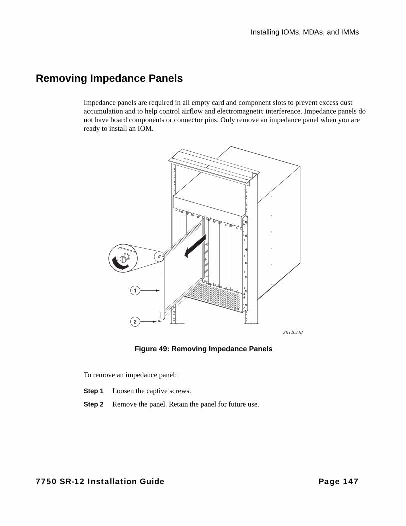
Installing IOMs, MDAs, and IMMs
Removing Impedance Panels
Impedance panels are required in all empty card and component slots to prevent excess dust accumulation and to help control airflow and electromagnetic interference. Impedance panels do not have board components or connector pins. Only remove an impedance panel when you are ready to install an IOM.
Figure 49: Removing Impedance Panels
To remove an impedance panel:
Step 1 Loosen the captive screws.
Step 2 Remove the panel. Retain the panel for future use.
2
1
SR12023B
7750 SR-12 Installation Guide Page 147
Installing MDAs
Page 148 7750 SR-12 Installation Guide
Appendix A: LEDs
In This Chapter
This section describes the 7750 SR-12 power supply, SF/CPM, IOM, and MDA LEDs. For information about IMM LEDs, see 7x50 SR/ESS IMM Installation Guide.
The following LED descriptions are included:
• DC PEM-3 LED and Warning Symbol on page 150
• AC Power Supply Module LEDs on page 151
• SF/CPM LEDs on page 152
• IOM LED on page 155
• MDA LEDs on page 156
7750 SR-12 Installation Guide Page 149
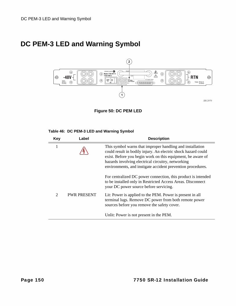
DC PEM-3 LED and Warning Symbol
DC PEM-3 LED and Warning Symbol
Figure 50: DC PEM LED
SR12070
2
1
Table 46: DC PEM-3 LED and Warning Symbol
Key Label Description
1 This symbol warns that improper handling and installation could result in bodily injury. An electric shock hazard could exist. Before you begin work on this equipment, be aware of hazards involving electrical circuitry, networking environments, and instigate accident prevention procedures.
For centralized DC power connection, this product is intended to be installed only in Restricted Access Areas. Disconnect your DC power source before servicing.
2 PWR PRESENT Lit: Power is applied to the PEM. Power is present in all terminal lugs. Remove DC power from both remote power sources before you remove the safety cover.
Unlit: Power is not present in the PEM.
Page 150 7750 SR-12 Installation Guide
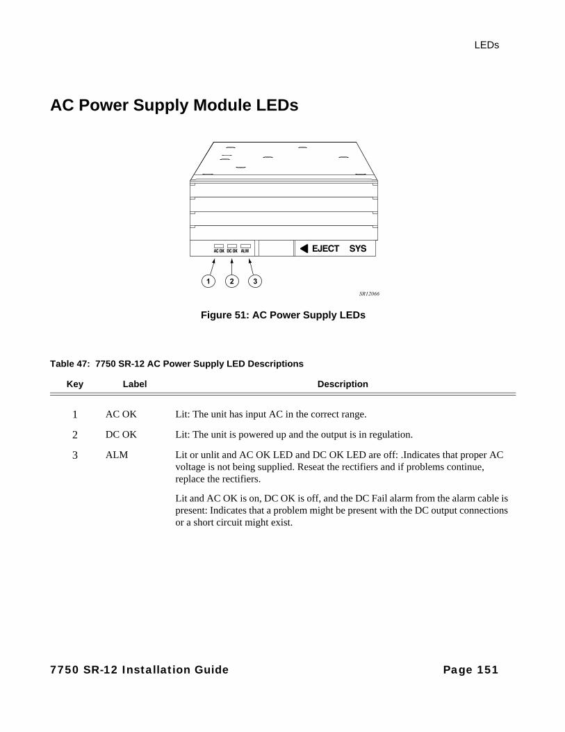
LEDs
AC Power Supply Module LEDs
Figure 51: AC Power Supply LEDs
Table 47: 7750 SR-12 AC Power Supply LED Descriptions
Key Label Description
1 AC OK Lit: The unit has input AC in the correct range.
2 DC OK Lit: The unit is powered up and the output is in regulation.
3 ALM Lit or unlit and AC OK LED and DC OK LED are off: .Indicates that proper AC voltage is not being supplied. Reseat the rectifiers and if problems continue, replace the rectifiers.
Lit and AC OK is on, DC OK is off, and the DC Fail alarm from the alarm cable is present: Indicates that a problem might be present with the DC output connections or a short circuit might exist.
SR12066
2 31
7750 SR-12 Installation Guide Page 151

SF/CPM LEDs
SF/CPM LEDs
Figure 52 displays the LEDs on the front panel. Table 48 describes the fields and LED states.
Figure 52: SF/CPM LEDs
Table 48: SF/CPM Field Descriptions
Key Label/Part Subcategory
Description
1 Reset A recessed button used to restart the SF/CPM. Insert a small object such as a pen tip to press the button.
2 Status • Green: Operationally up and administratively up.• Amber: Operationally down but administratively up.• Unlit: Not operational.
3 Power • Blue: Power on.• Unlit: Power off.
4 Timing The Timing LED indicates system status and quality.• Green: Locked (operational state)• Green (blinking): Clock is in (internal) holdover state• Amber (blinking): Clock is in free running state• Unlit: Clock is not initialized.
SR_ESS7R3_005
1 2 4 6 8 10
3 5 7 9
Page 152 7750 SR-12 Installation Guide

LEDs
5 M/S Ctl Master/Slave SF/CPM designation:• Green: Indicates that the SF/CPM is designated as the primary SF/CPM
in a redundant system.• Green (blinking): Indicates that the SF/CPM is operating as the
secondary SF/CPM in a redundant configuration.
Ref Master/Slave clocking reference designation:• Green: Indicates that the SF/CPM is designated as the primary clocking
reference in a redundant system.• Green (blinking): Indicates that the SF/CPM is operating as the
secondary clocking reference in a redundant system.• Unlit: Indicates that the clock is not initialized.Note: The clock is only required for SONET and/or 10GbE WAN operations.
6 Reference 1, 2 The Reference LEDs indicate the status and quality of the individual timing sources.• Green: Qualified and selected as clock reference input.• Green (blinking): Qualified but set as the standby clock reference.• Amber: The reference is enabled (no shutdown) but not qualified.• Unlit: Not in use, not configured.
3 Building integrated timing supply (BITS) network clocking: Derives network timing from the central office (CO) BITS.• Green: Qualified and selected as clock reference input.• Green (blinking): Qualified but set as the standby clock reference.• Amber: The reference is enabled (no shutdown) but not qualified.• Unlit: Not in use, not configured.
7 Power Supply 1,2,3,4 • Green: Indicates that a power entry module is installed and operational in the associated slot.
• Amber: Indicates an error condition with an installed power entry module in the associated slot.
• Unlit: Indicates that a power entry module is not installed or not recognized.
• In the SR-12 model, the power supply LEDs on the secondary SFM will light similarly to the primary SFM. A fault is indicated in one SFM if the primary power supply LED and the comparable LED differ. The SFM should be returned for repair. This might indicate a fault in the SFM fuse system.
Table 48: SF/CPM Field Descriptions (Continued)
Key Label/Part Subcategory
Description
7750 SR-12 Installation Guide Page 153
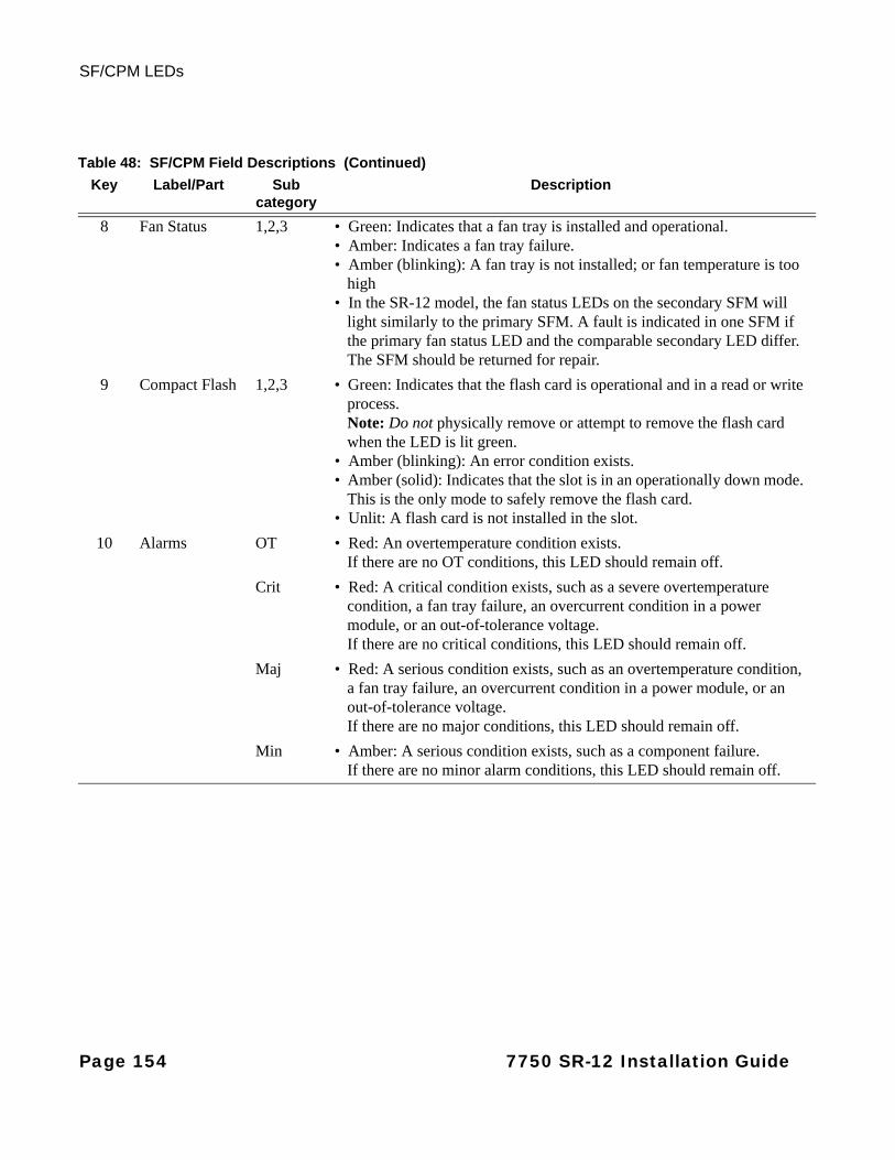
SF/CPM LEDs
8 Fan StatusFan Status LEDs
1,2,3 • Green: Indicates that a fan tray is installed and operational.• Amber: Indicates a fan tray failure.• Amber (blinking): A fan tray is not installed; or fan temperature is too
high• In the SR-12 model, the fan status LEDs on the secondary SFM will
light similarly to the primary SFM. A fault is indicated in one SFM if the primary fan status LED and the comparable secondary LED differ. The SFM should be returned for repair.
9 Compact Flash 1,2,3 • Green: Indicates that the flash card is operational and in a read or write process. Note: Do not physically remove or attempt to remove the flash card when the LED is lit green.
• Amber (blinking): An error condition exists. • Amber (solid): Indicates that the slot is in an operationally down mode.
This is the only mode to safely remove the flash card. • Unlit: A flash card is not installed in the slot.
10 Alarms OT • Red: An overtemperature condition exists. If there are no OT conditions, this LED should remain off.
Crit • Red: A critical condition exists, such as a severe overtemperature condition, a fan tray failure, an overcurrent condition in a power module, or an out-of-tolerance voltage. If there are no critical conditions, this LED should remain off.
Maj • Red: A serious condition exists, such as an overtemperature condition, a fan tray failure, an overcurrent condition in a power module, or an out-of-tolerance voltage. If there are no major conditions, this LED should remain off.
Min • Amber: A serious condition exists, such as a component failure. If there are no minor alarm conditions, this LED should remain off.
Table 48: SF/CPM Field Descriptions (Continued)
Key Label/Part Subcategory
Description
Page 154 7750 SR-12 Installation Guide
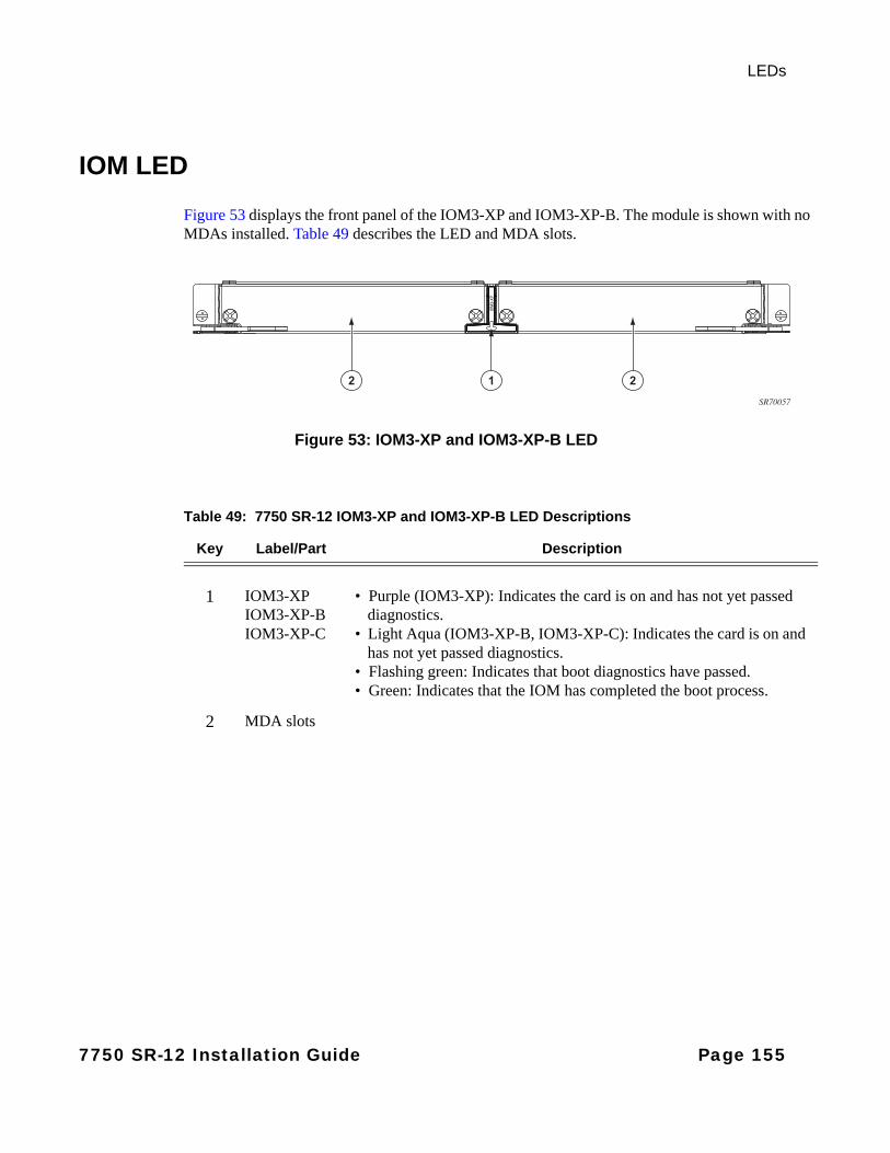
LEDs
IOM LED
Figure 53 displays the front panel of the IOM3-XP and IOM3-XP-B. The module is shown with no MDAs installed. Table 49 describes the LED and MDA slots.
Figure 53: IOM3-XP and IOM3-XP-B LED
12 2
SR70057
Table 49: 7750 SR-12 IOM3-XP and IOM3-XP-B LED Descriptions
Key Label/Part Description
1 IOM3-XP IOM3-XP-BIOM3-XP-C
• Purple (IOM3-XP): Indicates the card is on and has not yet passed diagnostics.
• Light Aqua (IOM3-XP-B, IOM3-XP-C): Indicates the card is on and has not yet passed diagnostics.
• Flashing green: Indicates that boot diagnostics have passed.• Green: Indicates that the IOM has completed the boot process.
2 MDA slots
7750 SR-12 Installation Guide Page 155
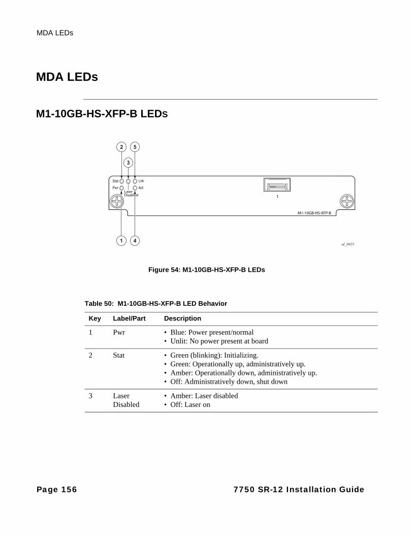
MDA LEDs
MDA LEDs
M1-10GB-HS-XFP-B LEDS
Figure 54: M1-10GB-HS-XFP-B LEDs
al_0431
2 5
3
1 4
Table 50: M1-10GB-HS-XFP-B LED Behavior
Key Label/Part Description
1 Pwr • Blue: Power present/normal• Unlit: No power present at board
2 Stat • Green (blinking): Initializing.• Green: Operationally up, administratively up.• Amber: Operationally down, administratively up.• Off: Administratively down, shut down
3 LaserDisabled
• Amber: Laser disabled• Off: Laser on
Page 156 7750 SR-12 Installation Guide
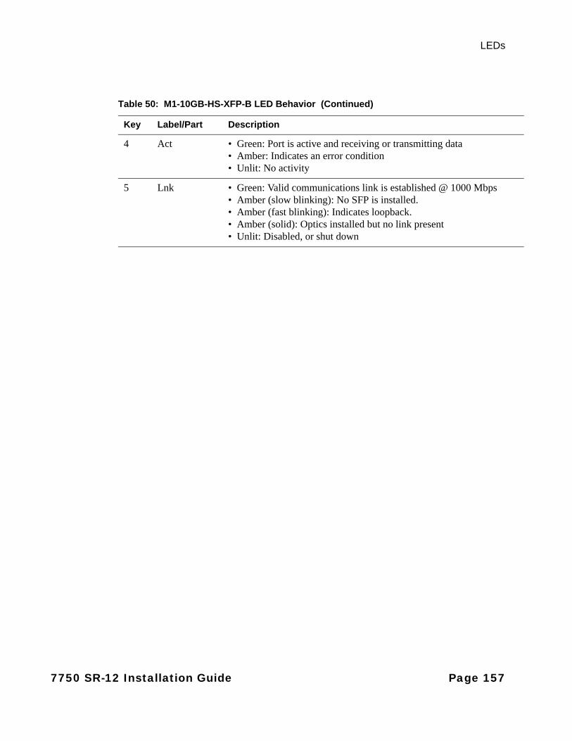
LEDs
4 Act • Green: Port is active and receiving or transmitting data• Amber: Indicates an error condition• Unlit: No activity
5 Lnk • Green: Valid communications link is established @ 1000 Mbps• Amber (slow blinking): No SFP is installed.• Amber (fast blinking): Indicates loopback.• Amber (solid): Optics installed but no link present• Unlit: Disabled, or shut down
Table 50: M1-10GB-HS-XFP-B LED Behavior (Continued)
Key Label/Part Description
7750 SR-12 Installation Guide Page 157

MDA LEDs
Page 158 7750 SR-12 Installation Guide
Appendix B: Field ReplaceableUnits
In This Chapter
This chapter provides information about field replaceable units (FRUs) in the 7750 SR-12 chassis.
Topics in this chapter include:
• Air Filter Tray on page 160
• SF/CPMs on page 164
• IOMs and IMMs on page 168
• MDAs on page 174
• Power Modules on page 179
• Impeller Trays on page 190
7750 SR-12 Installation Guide Page 159

Air Filter Tray
Air Filter Tray
Notes:
• Alcatel-Lucent recommends inspecting the air filter(s) on a monthly basis. If dirt and dust accumulation are found, Alcatel-Lucent recommends replacing the air filter as the most optimal course of corrective action. If desired, customers may also clean the air filter for reuse. If cleaning the filter of a system in-service, use a spare filter as the initial replacement. Do not run the system for extended periods of time without a filter installed. The filter is made of a foam material and “dry cleaning” by use of a vacuum is recommended. After cleaning, inspect the filter to insure the filter has not been damaged prior to re-use.
Notes:
• The air filter tray is accessible from the front of the chassis.
Page 160 7750 SR-12 Installation Guide

Field Replaceable Units
Removing the Air Filter Tray
Figure 55: Removing the Air Filter Tray
2
1SR12009A
Table 51: Filter Tray Features
Key Description
1 Captive screws
2 Filter vent faceplate
7750 SR-12 Installation Guide Page 161
Air Filter Tray
To remove the air filter:
Step 1 Unpack the replacement fan tray from the protective packaging and place on an anti-static surface.
Step 2 In the lower front of the chassis, below the lower cable management tray, use a flathead screwdriver to loosen the captive screws on the filter vent faceplate (Figure 55).
Step 3 Remove the filter vent faceplate.
Step 4 Release the filter tray from the internal brackets and pull the tray out of the chassis.
Page 162 7750 SR-12 Installation Guide
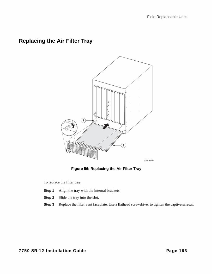
Field Replaceable Units
Replacing the Air Filter Tray
Figure 56: Replacing the Air Filter Tray
To replace the filter tray:
Step 1 Align the tray with the internal brackets.
Step 2 Slide the tray into the slot.
Step 3 Replace the filter vent faceplate. Use a flathead screwdriver to tighten the captive screws.
2
1
SR12008A
7750 SR-12 Installation Guide Page 163
SF/CPMs
SF/CPMs
Warnings and Notes
Warning:
• Do not remove an SF/CPM if a compact flash LED is lit green. If green, a read/write action is in progress.
• Electrostatic discharge (ESD) damage can occur if IOMs, SF/CPMs, or MDAs are mishandled. Always wear an ESD-preventive wrist or ankle strap connected to the grounding plug on the front of the chassis. Always place router components on an anti-static surface.
• Impedance panels are required in all empty card and component slots to prevent excess dust accumulation and to help control airflow and electromagnetic interference.
Notes:
General:• When replacing SF/CPM modules, configuration modifications are not required.
• All 7750 routers require at least one SF/CPM.
• Do not force an IOM into an SF/CPM slot.
• Do not force an SF/CPM into an IOM slot.
• When you remove an SF/CPM, always use the ejector levers to make sure that the connector pins disconnect from the backplane.
• Removing an SF/CPM module in a non-redundant system causes the system to shut down. If you are not immediately installing a replacement SF/CPM module, replace the empty slot with a blank panel and power off the system until the SF/CPM module is replaced
7750 SR-12:• Accommodates two SF/CPMs, one active and one standby.
• The SF/CPMs must be installed in center slots A or B.
Page 164 7750 SR-12 Installation Guide

Field Replaceable Units
Removing an SF/CPM
Figure 57: Removing an SF/CPM Module
To remove an SF/CPM:
Step 1 If applicable, eject all compact flash cards from their slots. The compact flash LEDs displayed on the SF/CPM must be either unlit or blinking amber before ejecting the flash card.
Step 2 Disconnect the cable connections to the SF/CPM.
Step 3 Loosen the SF/CPM captive screws.
Step 4 Simultaneously, rotate the ejector levers inward to unlock the panel.
Step 5 Pull the card out of the slot. Place on an anti-static surface or in an anti-static bag.
2
1
SR12028A
7750 SR-12 Installation Guide Page 165

SF/CPMs
Replacing an SF/CPM
NOTE: Each SF/CPM module has two ejector levers which seat and release the card from the backplane connectors. During installation, the ejector levers must be positioned inward and then rotated outward to lock into place. The ejector levers must remain in the locked position while the card is installed in the chassis.
Figure 58: Replacing the SF/CPM Module
2
1
SR12027A
Page 166 7750 SR-12 Installation Guide

Field Replaceable Units
To install an SF/CPM:
Step 1 Remove the SF/CPM module from the packaging. Do not touch the printed circuit board or connector pins.
Step 2 The SF/CPM must be installed in the center chassis slots labeled A or B.
Holding the SF/CPM by the edges, align the card with center slot guide A or B. Slide the card inward until the connectors are seated in the back and the faceplate is flush with the front of the chassis.
Step 3 Simultaneously, rotate the ejector levers outward to lock the backplane connectors and SF/CPM in place.
If an SF/CPM ejector lever does not shift to the locked position, the card is probably not seated properly in the backplane. Pull the card out halfway and then reinsert it. Shift the levers to the locked position.
Step 4 Secure the card in place by tightening the captive screws. The ejector levers must remain in the locked position while the card is installed in the chassis.
Step 5 Reinsert compact flash cards into the appropriate CF slots.
7750 SR-12 Installation Guide Page 167
IOMs and IMMs
IOMs and IMMs
Warnings and Notes
Warning:
• Electrostatic discharge (ESD) damage can occur if IOMs, IMMs, SF/CPMs, or MDAs are mishandled. Always wear an ESD-preventive wrist or ankle strap connected to the grounding plug on the front of the chassis. Always place router components on an anti-static surface.
• Blank panels and faceplates are required in all empty card and component slots to prevent excess dust accumulation and to help control airflow and electromagnetic interference.
Notes:
General:• When replacing IOMs, IMMs, MDAs, the card, and port configurations must be shut down.
• All 7750 routers require at least one IOM and one MDA.
• When you remove an IOM or IMM, always use the ejector levers to make sure that the connector pins disconnect from the backplane.
• Removing an IOM or IMM will not cause the system to shut down. If you are not immediately installing a replacement IOM or IMM, replace the empty slot with a blank panel.
• If you are using IOM3-XP or IOM3-XP-Bs in your system, you must use impedance panels in all empty slots.
7750 SR-12:
• Accommodates a maximum of ten IOMs or IMMs.
Page 168 7750 SR-12 Installation Guide
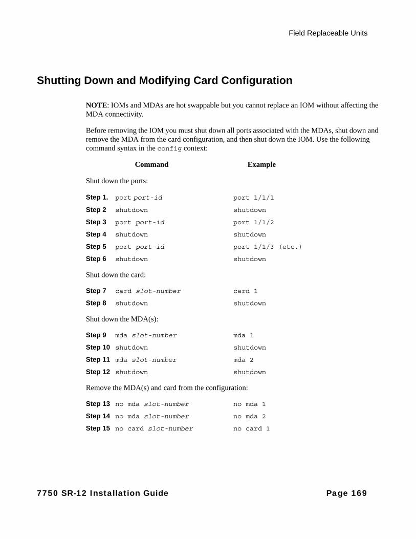
Field Replaceable Units
Shutting Down and Modifying Card Configuration
NOTE: IOMs and MDAs are hot swappable but you cannot replace an IOM without affecting the MDA connectivity.
Before removing the IOM you must shut down all ports associated with the MDAs, shut down and remove the MDA from the card configuration, and then shut down the IOM. Use the following command syntax in the config context:
Command Example
Shut down the ports:
Step 1. port port-id port 1/1/1
Step 2 shutdown shutdown
Step 3 port port-id port 1/1/2
Step 4 shutdown shutdown
Step 5 port port-id port 1/1/3 (etc.)
Step 6 shutdown shutdown
Shut down the card:
Step 7 card slot-number card 1
Step 8 shutdown shutdown
Shut down the MDA(s):
Step 9 mda slot-number mda 1
Step 10 shutdown shutdown
Step 11 mda slot-number mda 2
Step 12 shutdown shutdown
Remove the MDA(s) and card from the configuration:
Step 13 no mda slot-number no mda 1
Step 14 no mda slot-number no mda 2
Step 15 no card slot-number no card 1
7750 SR-12 Installation Guide Page 169
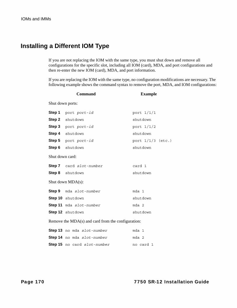
IOMs and IMMs
Installing a Different IOM Type
If you are not replacing the IOM with the same type, you must shut down and remove all configurations for the specific slot, including all IOM (card), MDA, and port configurations and then re-enter the new IOM (card), MDA, and port information.
If you are replacing the IOM with the same type, no configuration modifications are necessary. The following example shows the command syntax to remove the port, MDA, and IOM configurations:
Command Example
Shut down ports:
Step 1 port port-id port 1/1/1
Step 2 shutdown shutdown
Step 3 port port-id port 1/1/2
Step 4 shutdown shutdown
Step 5 port port-id port 1/1/3 (etc.)
Step 6 shutdown shutdown
Shut down card:
Step 7 card slot-number card 1
Step 8 shutdown shutdown
Shut down MDA(s):
Step 9 mda slot-number mda 1
Step 10 shutdown shutdown
Step 11 mda slot-number mda 2
Step 12 shutdown shutdown
Remove the MDA(s) and card from the configuration:
Step 13 no mda slot-number mda 1
Step 14 no mda slot-number mda 2
Step 15 no card slot-number no card 1
Page 170 7750 SR-12 Installation Guide

Field Replaceable Units
Use the following command syntax to reconfigure the card, MDA, and port configurations:
Command Example
Configure slot and card type:
Step 1 card slot-number card 1
Step 2 card-type card-type card-type iom-20g
Step 3 no shutdown no shutdown
Configure MDA slot and type:
Step 4 mda slot-number mda 1
Step 5 mda mda-type mda-type m1-10gb-lw/r-sm
Step 6 no shutdown no shutdown
Step 7 mda slot-number mda 2
Step 8 mda mda-type mda-type m60-10/100eth-tx
Step 9 no shutdown no shutdown
Configure port:
Step 10 port port-id port 1/1/1
Step 11 no shutdown no shutdown
Continue port configurations as required.
7750 SR-12 Installation Guide Page 171
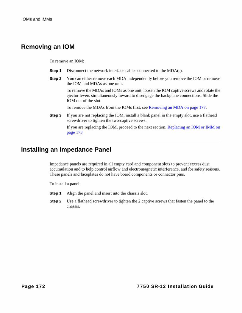
IOMs and IMMs
Removing an IOM
To remove an IOM:
Step 1 Disconnect the network interface cables connected to the MDA(s).
Step 2 You can either remove each MDA independently before you remove the IOM or remove the IOM and MDAs as one unit.
To remove the MDAs and IOMs as one unit, loosen the IOM captive screws and rotate the ejector levers simultaneously inward to disengage the backplane connections. Slide the IOM out of the slot.
To remove the MDAs from the IOMs first, see Removing an MDA on page 177.
Step 3 If you are not replacing the IOM, install a blank panel in the empty slot, use a flathead screwdriver to tighten the two captive screws.
If you are replacing the IOM, proceed to the next section, Replacing an IOM or IMM on page 173.
Installing an Impedance Panel
Impedance panels are required in all empty card and component slots to prevent excess dust accumulation and to help control airflow and electromagnetic interference, and for safety reasons. These panels and faceplates do not have board components or connector pins.
To install a panel:
Step 1 Align the panel and insert into the chassis slot.
Step 2 Use a flathead screwdriver to tighten the 2 captive screws that fasten the panel to the chassis.
Page 172 7750 SR-12 Installation Guide
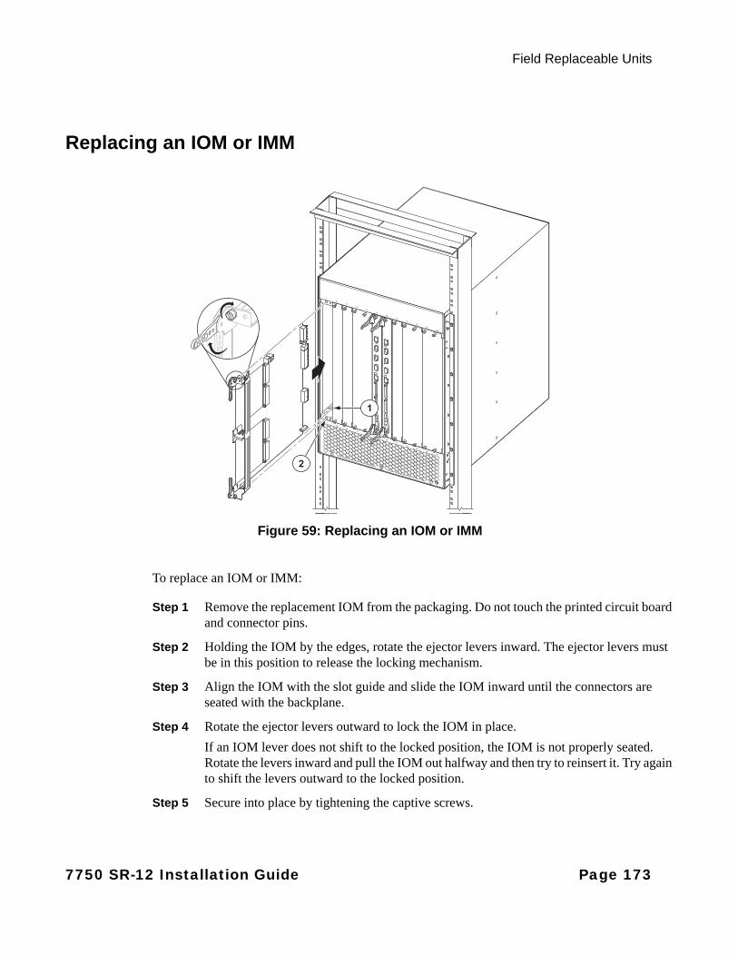
Field Replaceable Units
Replacing an IOM or IMM
Figure 59: Replacing an IOM or IMM
To replace an IOM or IMM:
Step 1 Remove the replacement IOM from the packaging. Do not touch the printed circuit board and connector pins.
Step 2 Holding the IOM by the edges, rotate the ejector levers inward. The ejector levers must be in this position to release the locking mechanism.
Step 3 Align the IOM with the slot guide and slide the IOM inward until the connectors are seated with the backplane.
Step 4 Rotate the ejector levers outward to lock the IOM in place.
If an IOM lever does not shift to the locked position, the IOM is not properly seated. Rotate the levers inward and pull the IOM out halfway and then try to reinsert it. Try again to shift the levers outward to the locked position.
Step 5 Secure into place by tightening the captive screws.
2
1
7750 SR-12 Installation Guide Page 173

MDAs
MDAs
Warnings and Notes
Danger:
• Only trained and qualified personnel should install or replace this equipment.
Warning:
• Electrostatic discharge (ESD) damage can occur if SF/CPMs, IOMs, or MDAs are mishandled. Always wear an ESD-preventive wrist or ankle strap and always connect an ESD strap to the grounding plug on the front of the chassis.
• Invisible laser radiation can be emitted from the aperture ports of an MDA when no cable is connected. Avoid exposure and do not stare into open apertures.
• Always place components on an anti-static surface.
• Do not power up a 7750 SR-12 router until all components are installed and verified.
• Use only approved small form factor pluggable fiber optic devices in MDA ports.
Notes:
General:• Ports cannot be provisioned if the MDA is not preprovisioned.
• Services cannot be provisioned if ports are not provisioned.
• MDAs can be attached to an IOM two ways:
→ Attach MDAs to the IOM and then load the unit into the chassis slot.
→ Install MDAs after the IOM is loaded in the chassis slot.
• For configuration purposes, MDA slots are number 1 (the left MDA slot) and 2 (the right MDA slot).
Page 174 7750 SR-12 Installation Guide
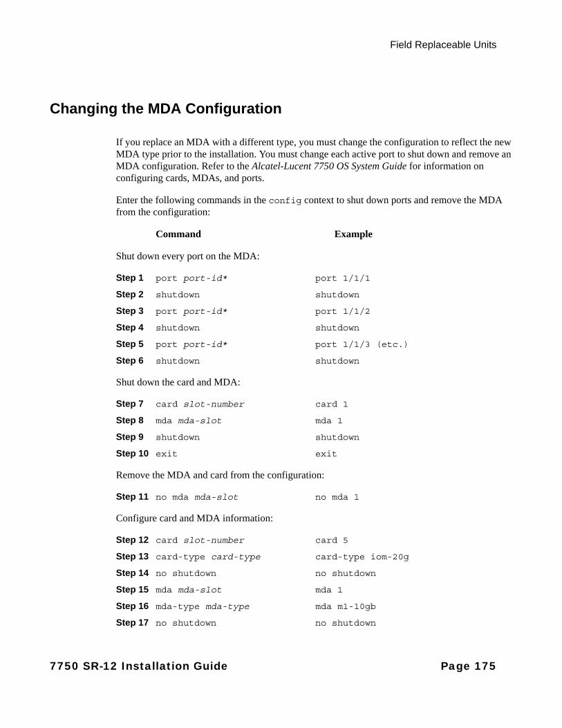
Field Replaceable Units
Changing the MDA Configuration
If you replace an MDA with a different type, you must change the configuration to reflect the new MDA type prior to the installation. You must change each active port to shut down and remove an MDA configuration. Refer to the Alcatel-Lucent 7750 OS System Guide for information on configuring cards, MDAs, and ports.
Enter the following commands in the config context to shut down ports and remove the MDA from the configuration:
Command Example
Shut down every port on the MDA:
Step 1 port port-id* port 1/1/1
Step 2 shutdown shutdown
Step 3 port port-id* port 1/1/2
Step 4 shutdown shutdown
Step 5 port port-id* port 1/1/3 (etc.)
Step 6 shutdown shutdown
Shut down the card and MDA:
Step 7 card slot-number card 1
Step 8 mda mda-slot mda 1
Step 9 shutdown shutdown
Step 10 exit exit
Remove the MDA and card from the configuration:
Step 11 no mda mda-slot no mda 1
Configure card and MDA information:
Step 12 card slot-number card 5
Step 13 card-type card-type card-type iom-20g
Step 14 no shutdown no shutdown
Step 15 mda mda-slot mda 1
Step 16 mda-type mda-type mda m1-10gb
Step 17 no shutdown no shutdown
7750 SR-12 Installation Guide Page 175

MDAs
Step 18 exit exit
Page 176 7750 SR-12 Installation Guide
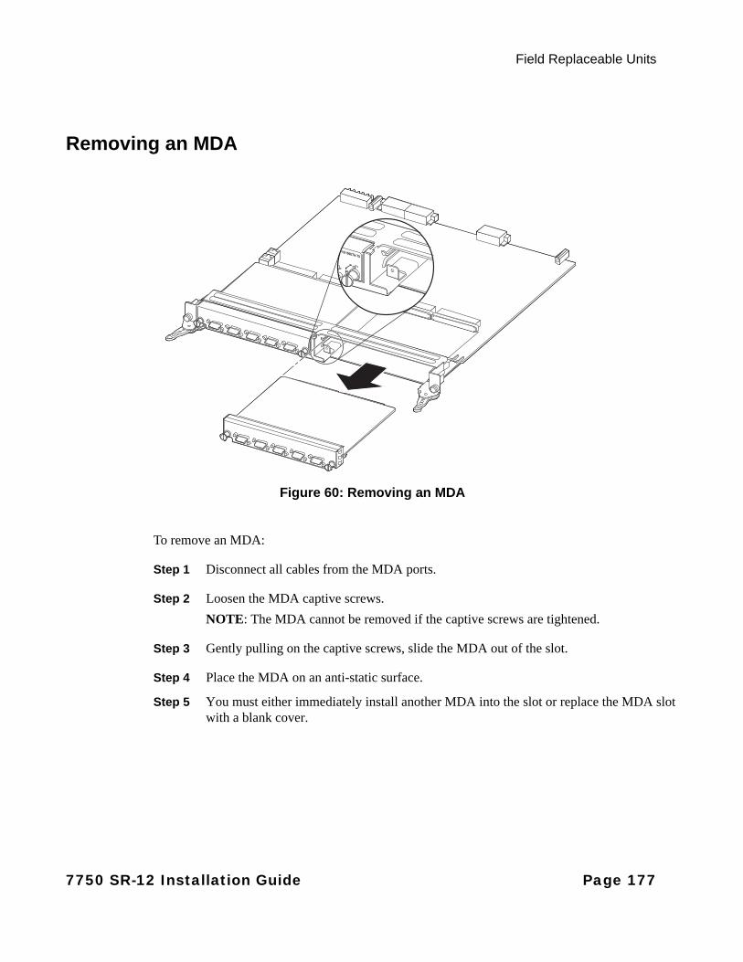
Field Replaceable Units
Removing an MDA
Figure 60: Removing an MDA
To remove an MDA:
Step 1 Disconnect all cables from the MDA ports.
Step 2 Loosen the MDA captive screws.
NOTE: The MDA cannot be removed if the captive screws are tightened.
Step 3 Gently pulling on the captive screws, slide the MDA out of the slot.
Step 4 Place the MDA on an anti-static surface.
Step 5 You must either immediately install another MDA into the slot or replace the MDA slot with a blank cover.
7750 SR-12 Installation Guide Page 177
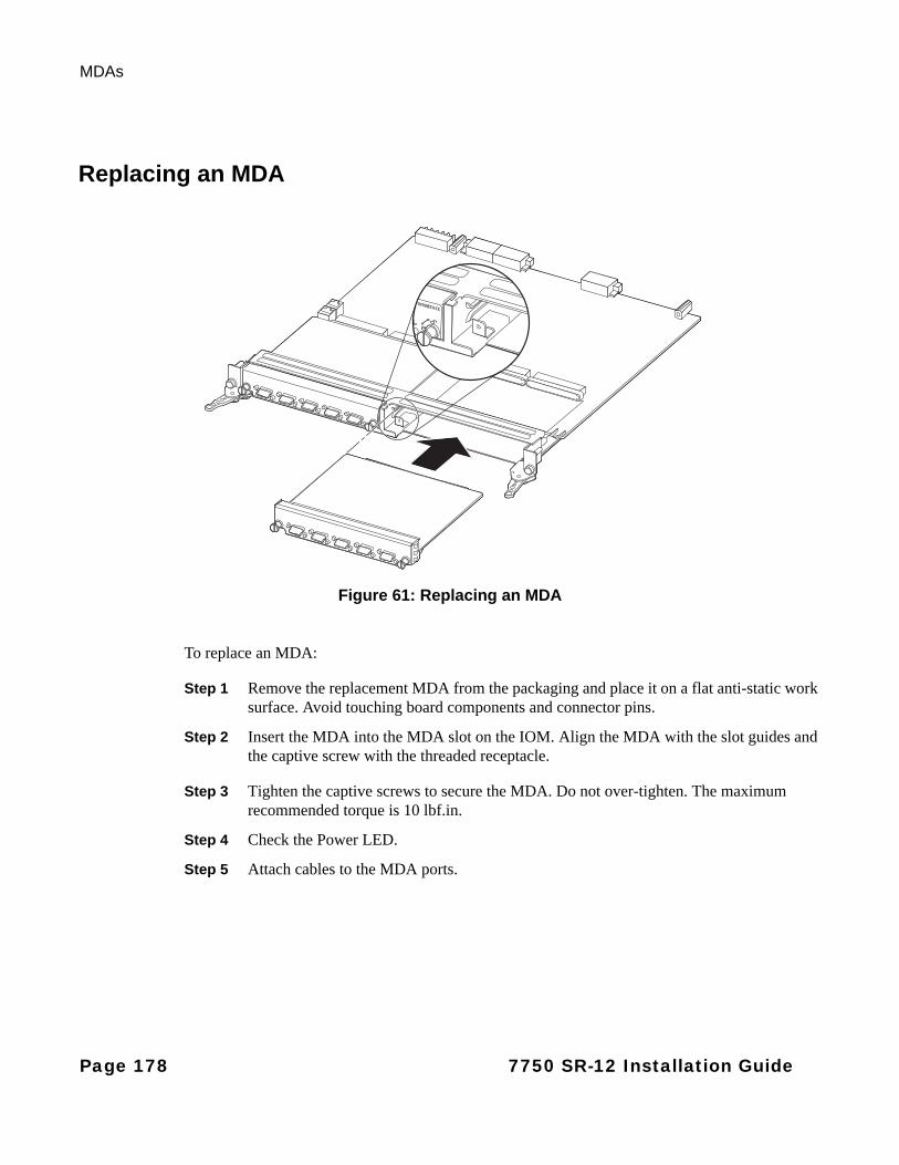
MDAs
Replacing an MDA
Figure 61: Replacing an MDA
To replace an MDA:
Step 1 Remove the replacement MDA from the packaging and place it on a flat anti-static work surface. Avoid touching board components and connector pins.
Step 2 Insert the MDA into the MDA slot on the IOM. Align the MDA with the slot guides and the captive screw with the threaded receptacle.
Step 3 Tighten the captive screws to secure the MDA. Do not over-tighten. The maximum recommended torque is 10 lbf.in.
Step 4 Check the Power LED.
Step 5 Attach cables to the MDA ports.
Page 178 7750 SR-12 Installation Guide
Field Replaceable Units
Power Modules
This section covers:
• Removing a DC PEM on page 181
• Replacing a DC PEM on page 184
• AC Power Shelves and Rectifiers on page 187
• Disconnecting AC Power Cables from an AC Power Shelf on page 187
Warnings and Notes
Danger:
• Only trained and qualified personnel should install or replace this equipment and connect the power cables.
• Even though the power supply modules are hot swappable, for extra safety, you can turn off power at the power source and disconnect and unplug the power cables before you remove and replace a power supply module.
• You must use power cables which meet local electrical code requirements.
• If the PEM-3 LED is lit, DC power is present. Do not touch. Turn off the remote power from both power sources to the PEM before you remove the safety cover.
Warning:
• Do not install equipment that appears to be damaged.
• Impedance panels are required in all empty component slots to prevent excess dust accumulation and to help control airflow and electromagnetic interference. Impedance panels do not have board components or connector pins.
• The 7750 SR-12 router with DC PEMs should be installed only in restricted access areas (such as dedicated equipment rooms and electrical closets) in accordance with Articles 110-26 and 110-27 of the most recent National Electrical Code ANSI/NFPA 70.
• Electrostatic discharge (ESD) damage can occur if components are mishandled. Always wear an ESD-preventive wrist or ankle strap and always connect an ESD strap to the grounding plug on the front of the chassis.
7750 SR-12 Installation Guide Page 179

Power Modules
Warning: The SR/ESS-12 power subsystem is based on a diode-or’d design for redundancy purposes. For this reason, a small amount of voltage (relative to ground) of approximately 3-4 volts is measured/observed on the (-) return feed, even when the branch circuit and PEM Breaker are shut off (assuming the second PEM remains powered/on). If this is a concern during the upgrade process, follow the steps below:
Step 1 Shut the branch breaker/ fuse to the redundant PEM being replaced.
Step 2 Shut the breaker off on the PEM itself.
Step 3 Pull the PEM out of its slot. This ensures no remaining voltage on the return feed.
Step 4 Remove the return cable from the PEM that has been pulled out.
By removing the PEM prior to handling the return cable, no voltage remains on the line.
Notes:
• The 7750 SR-12 requires a minimum of one DC PEM to operate, but two are recommended for redundancy.
• For full redundancy, each power supply module should be attached to an independent power source with a dedicated circuit breaker.
• AC power rectifiers can convert AC power from an external AC power source into DC power that is suitable for the SR-12 router. AC power shelves and rectifiers are available from Alcatel-Lucent. If AC power is used, at least one AC power shelf with two rectifiers must be used.
• In the event of a PEM, AC power rectifier, or AC power shelf failure, the entire individual unit must be replaced. There are no field serviceable parts inside the components.
Page 180 7750 SR-12 Installation Guide
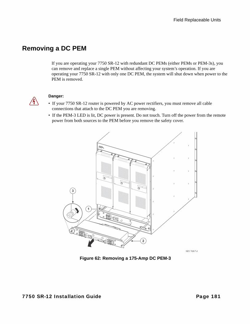
Field Replaceable Units
Removing a DC PEM
If you are operating your 7750 SR-12 with redundant DC PEMs (either PEMs or PEM-3s), you can remove and replace a single PEM without affecting your system’s operation. If you are operating your 7750 SR-12 with only one DC PEM, the system will shut down when power to the PEM is removed.
3
Figure 62: Removing a 175-Amp DC PEM-3
Danger:
• If your 7750 SR-12 router is powered by AC power rectifiers, you must remove all cable connections that attach to the DC PEM you are removing.
• If the PEM-3 LED is lit, DC power is present. Do not touch. Turn off the power from the remote power from both sources to the PEM before you remove the safety cover.
2
3
1
SR12082A
7750 SR-12 Installation Guide Page 181
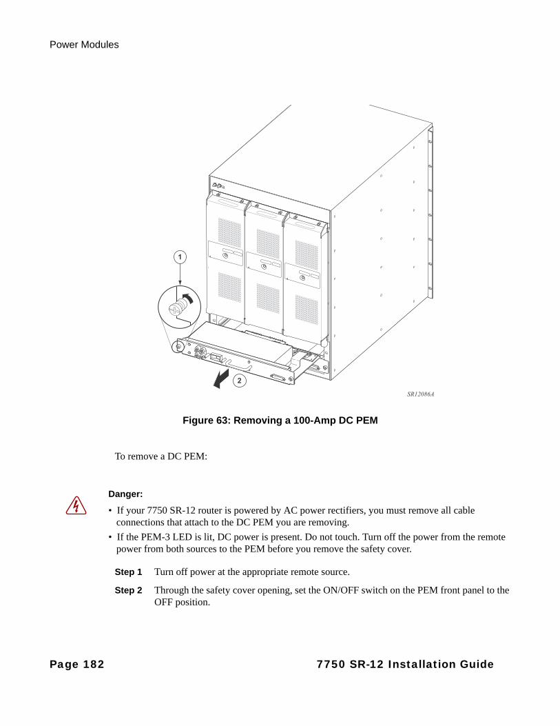
Power Modules
100-Amp DC PEM
Figure 63: Removing a 100-Amp DC PEM
To remove a DC PEM:
Step 1 Turn off power at the appropriate remote source.
Step 2 Through the safety cover opening, set the ON/OFF switch on the PEM front panel to the OFF position.
2
1
SR12086A
Danger:
• If your 7750 SR-12 router is powered by AC power rectifiers, you must remove all cable connections that attach to the DC PEM you are removing.
• If the PEM-3 LED is lit, DC power is present. Do not touch. Turn off the power from the remote power from both sources to the PEM before you remove the safety cover.
Page 182 7750 SR-12 Installation Guide
Field Replaceable Units
Step 3 Verify that the appropriate Power Supply LED on the SF/CPM is amber.
Step 4 Loosen the captive screws and remove the safety cover.
Step 5 Disconnect the VDC and RTN cables.
Step 6 Loosen the captive screws and slide the DC PEM out of the slot (Figure 63).
Step 7 If you do not replace the PEM immediately, install a blank panel to prevent excess dust accumulation and to help control airflow and electromagnetic interference.
7750 SR-12 Installation Guide Page 183
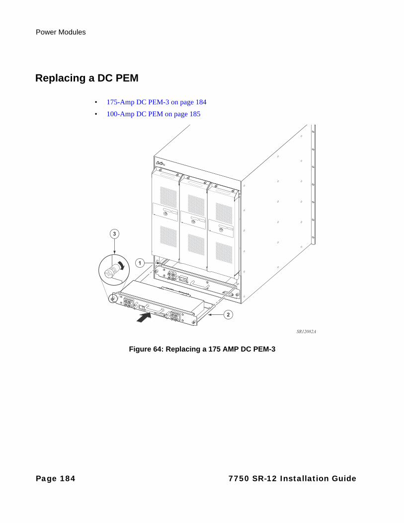
Power Modules
Replacing a DC PEM
• 175-Amp DC PEM-3 on page 184
• 100-Amp DC PEM on page 185175-Amp DC PEM-3
Figure 64: Replacing a 175 AMP DC PEM-3
2
3
1
SR12082A
Page 184 7750 SR-12 Installation Guide

Field Replaceable Units
100-Amp DC PEM
Figure 65: Replacing a 100-Amp DC PEM
To replace a DC PEM:
Step 1 Remove the replacement DC PEM from the packaging.
Step 2 Make sure that the circuit breaker (ON/OFF) on the PEM is in the OFF ( O ) position.
Step 3 Align the PEM with the appropriate power slot. Slide the unit into the slot until the connectors are seated with the receptacle in the rear of the slot.
Step 4 Secure into place by tightening the captive screws.
Step 5 Reconnect the VDC and RTN cables that are terminated with a UL-listed 2-hole lug with 1/4-inch (.635 cm) diameter holes on 3/4-inch (1.905 cm) spacing.
2
3
1
SR12083A
7750 SR-12 Installation Guide Page 185
Power Modules
Step 6 Make sure that the VDC and RTN cables from each power supply is connected to separate circuit breakers.
Step 7 Replace the safety cover and secure into place by tightening the captive screws.
Step 8 Through the safety cover opening, set the ON/OFF switch on the PEM front panel to the ON position.
Step 9 Turn on the power at the appropriate remote source.
The SR/ESS-12 power subsystem is a diode-or’d design for redundancy purposes. For this reason, the presence of a small amount of voltage (relative to ground) of approximately 3V to 4V will be measured/observed on the (-) return feed even when the branch circuit and PEM Breaker are shut off (assuming the second PEM remains powered/on). If a customer is concerned about this when upgrading, perform the following steps:
Step 1 Shut branch breaker/fuse to the redundant PEM being replaced.
Step 2 Shut the breaker off on the PEM itself.
Step 3 Pull the PEM out of its slot (this will ensure no remaining voltage on return feed).
Step 4 Remove return cable from the PEM that has been removed.
By removing the PEM prior to handling the return cable, you ensure that no voltage remains on the line.
Page 186 7750 SR-12 Installation Guide
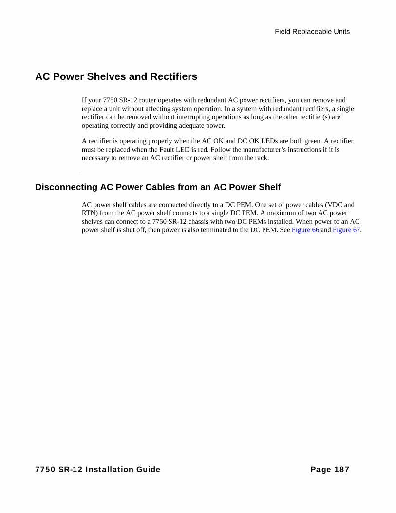
Field Replaceable Units
AC Power Shelves and Rectifiers
If your 7750 SR-12 router operates with redundant AC power rectifiers, you can remove and replace a unit without affecting system operation. In a system with redundant rectifiers, a single rectifier can be removed without interrupting operations as long as the other rectifier(s) are operating correctly and providing adequate power.
A rectifier is operating properly when the AC OK and DC OK LEDs are both green. A rectifier must be replaced when the Fault LED is red. Follow the manufacturer’s instructions if it is necessary to remove an AC rectifier or power shelf from the rack.
Disconnecting AC Power Cables from an AC Power Shelf
AC power shelf cables are connected directly to a DC PEM. One set of power cables (VDC and RTN) from the AC power shelf connects to a single DC PEM. A maximum of two AC power shelves can connect to a 7750 SR-12 chassis with two DC PEMs installed. When power to an AC power shelf is shut off, then power is also terminated to the DC PEM. See Figure 66 and Figure 67.
7750 SR-12 Installation Guide Page 187
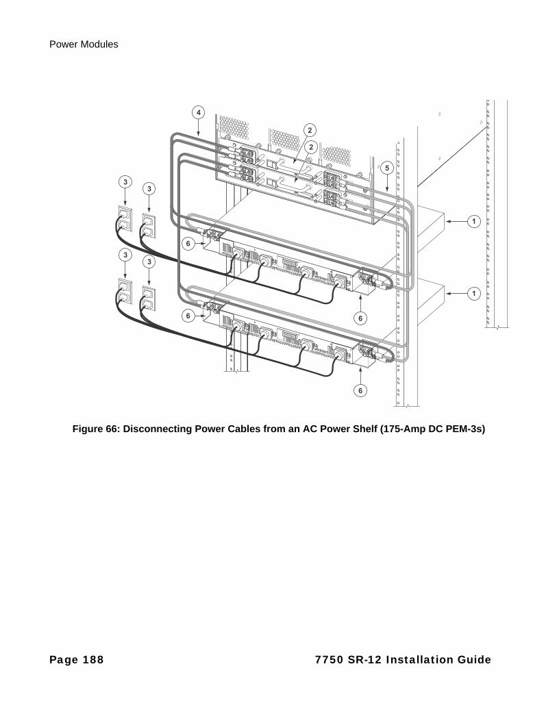
Power Modules
Figure 66: Disconnecting Power Cables from an AC Power Shelf (175-Amp DC PEM-3s)
5
2
2
4
3
3
3
3
1
1
6
6
6
6
Page 188 7750 SR-12 Installation Guide
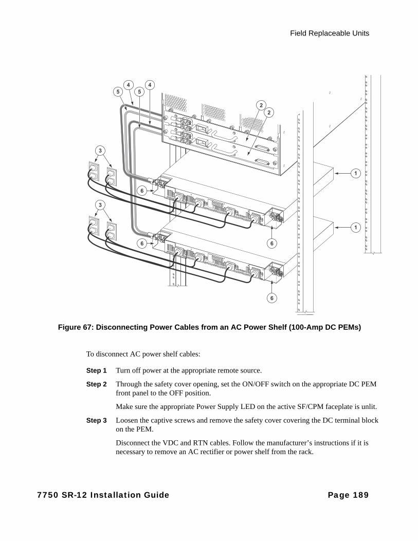
Field Replaceable Units
Figure 67: Disconnecting Power Cables from an AC Power Shelf (100-Amp DC PEMs)
To disconnect AC power shelf cables:
Step 1 Turn off power at the appropriate remote source.
Step 2 Through the safety cover opening, set the ON/OFF switch on the appropriate DC PEM front panel to the OFF position.
Make sure the appropriate Power Supply LED on the active SF/CPM faceplate is unlit.
Step 3 Loosen the captive screws and remove the safety cover covering the DC terminal block on the PEM.
Disconnect the VDC and RTN cables. Follow the manufacturer’s instructions if it is necessary to remove an AC rectifier or power shelf from the rack.
45
45
22
3
3
1
1
6
6
6
6
7750 SR-12 Installation Guide Page 189
Impeller Trays
Impeller Trays
Warnings and Notes
Warning:
• Always keep your fingers away from rotating blades.
• Verify that the fan blades have stopped rotating before removing the impeller trays.
Notes:
• There are three fan tray slots in the rear of the 7750 SR-12 chassis. The left slot is designated as fan tray #1, the middle slot is designated as fan tray #2, and the right slot is designated as fan tray #3.
• Impeller trays are hot-swappable. The 7750 SR-12 chassis will operate safely while you remove and replace the trays for up to approximately 2 minutes at an ambient temperature of 104° F (35° C).
• Immediately replace the tray as soon as a failure is detected.
• In the event of a single impeller failure, the entire tray must be replaced.
• To remove and replace impeller trays you must have access to the rear of the chassis. You must have enough room, at least 20-inches, to pull the tray completely out of the slot.
Notes:
• The air filter is accessible from the rear of the chassis. Use a flathead screwdriver to loosen the captive screws.
Notes:
• Alcatel-Lucent recommends inspecting the air filter(s) on a monthly basis. If dirt and dust accumulation are found, Alcatel-Lucent recommends replacing the air filter as the most optimal course of corrective action. If desired, customers may also clean the air filter for reuse. If cleaning the filter of a system in-service, use a spare filter as the initial replacement. Do not run the system for extended periods of time without a filter installed. The filter is made of a foam material and “dry cleaning” by use of a vacuum is recommended. After cleaning, inspect the filter to insure the filter has not been damaged prior to re-use.
Page 190 7750 SR-12 Installation Guide

Field Replaceable Units
Impeller Tray Failure
The following sections describe how the 7750 SR-12 chassis responds to an impeller fan tray failure.
STANDARD FAN TRAY FAILURE
If a single impeller within the Standard Fan tray fails, the remaining impeller speeds up to compensate for the lost impeller. The maximum air flow decreases from 500 CFM to 410 CFM.
ENHANCED FAN TRAY FAILURE
If a single impeller within an Enhanced Fan Tray fails, the remaining impeller speeds up to compensate for the lost impeller. The maximum air flow decreases from 1000 CFM to 850 CFM.
If a single tray fails, either under the fixed-control or SFM control, the remaining fan trays speed up to compensate for the failed fan tray.
7750 SR-12 Installation Guide Page 191
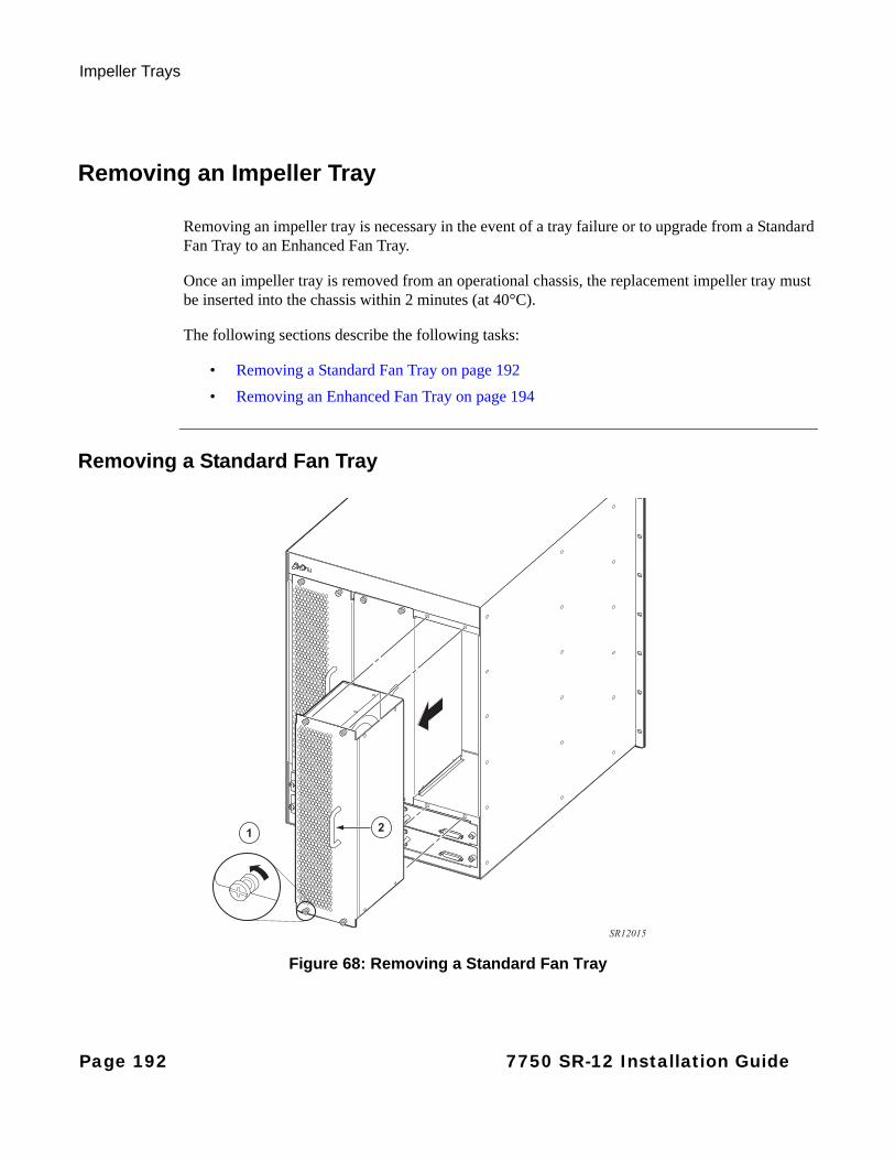
Impeller Trays
Removing an Impeller Tray
Removing an impeller tray is necessary in the event of a tray failure or to upgrade from a Standard Fan Tray to an Enhanced Fan Tray.
Once an impeller tray is removed from an operational chassis, the replacement impeller tray must be inserted into the chassis within 2 minutes (at 40°C).
The following sections describe the following tasks:
• Removing a Standard Fan Tray on page 192
• Removing an Enhanced Fan Tray on page 194
Removing a Standard Fan Tray
Figure 68: Removing a Standard Fan Tray
21
SR12015
Page 192 7750 SR-12 Installation Guide

Field Replaceable Units
To remove a Standard Fan Tray:
Step 1 Unpack the replacement Fan Tray from the protective packaging. Place the replacement impeller tray on an anti-static surface.
Step 2 Loosen the captive screws on the Standard Fan Tray faceplate (Figure 68).
Step 3 Grip the handle and pull the tray half way out of the chassis.
Step 4 Wait until the fans stop spinning (about 20 seconds) before removing the tray. Remove the tray completely out of the slot.
Caution: • DO NOT put your fingers or any tool in an impeller tray if the fans are still spinning.
7750 SR-12 Installation Guide Page 193
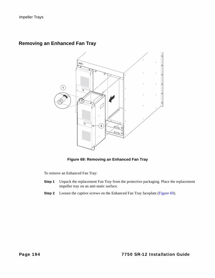
Impeller Trays
Removing an Enhanced Fan Tray
Figure 69: Removing an Enhanced Fan Tray
To remove an Enhanced Fan Tray:
Step 1 Unpack the replacement Fan Tray from the protective packaging. Place the replacement impeller tray on an anti-static surface.
Step 2 Loosen the captive screws on the Enhanced Fan Tray faceplate (Figure 69).
2
1
Page 194 7750 SR-12 Installation Guide
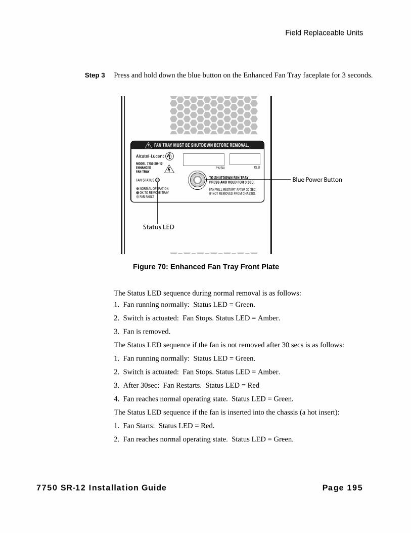
Field Replaceable Units
Step 3 Press and hold down the blue button on the Enhanced Fan Tray faceplate for 3 seconds.
Figure 70: Enhanced Fan Tray Front Plate
The Status LED sequence during normal removal is as follows:
1. Fan running normally: Status LED = Green.
2. Switch is actuated: Fan Stops. Status LED = Amber.
3. Fan is removed.
The Status LED sequence if the fan is not removed after 30 secs is as follows:
1. Fan running normally: Status LED = Green.
2. Switch is actuated: Fan Stops. Status LED = Amber.
3. After 30sec: Fan Restarts. Status LED = Red
4. Fan reaches normal operating state. Status LED = Green.
The Status LED sequence if the fan is inserted into the chassis (a hot insert):
1. Fan Starts: Status LED = Red.
2. Fan reaches normal operating state. Status LED = Green.
Status LED
Blue Power Button
7750 SR-12 Installation Guide Page 195
Impeller Trays
Step 4 Wait for the fans to stop and the fan status LED to turn amber.
Step 5 Grip the fan tray shelf handles located on the top and bottom of the front plate and pull the tray half way out of the chassis.
Step 6 Remove the tray completely out of the slot.
Notes:
• If you do not remove the fan tray within 30 seconds, the fan tray will automatically restart and resume operation.
• As part of the initialization and diagnostic startup, the Enhanced Fan Tray ramps to maximum fan speed for a brief period. Upon successful completion, the Enhanced Fan Tray slows down to the speed set by the SFM3 or thermistor for SFM1/2s.
Note: The Reduced-Depth Enhanced Fan Tray is exactly the same as the regular Enhanced Fan Tray in terms of functionality. The only difference is that the Reduced-Depth Enhanced Fan Tray does not have a handle on the front plate and is 2.7 in. less deep than the regular Enhanced Fan Tray.
Caution: • If you do not shutdown by pressing the blue button before removing the fan tray, the
impellers will still be spinning when the unit is removed. The moving impellors would present an injury risk if the operator inserted a body part inside the assembly when the impellers are turning.
• DO NOT put your fingers or any tool in an impeller tray if the fans are still spinning.
Page 196 7750 SR-12 Installation Guide
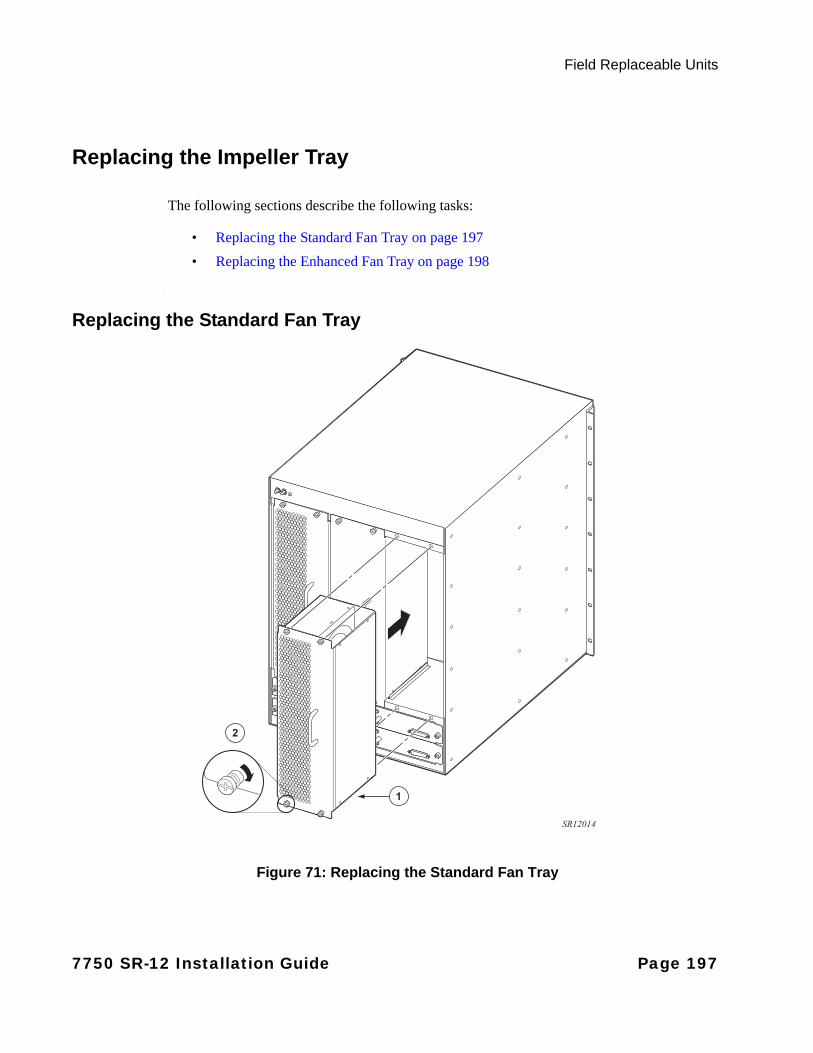
Field Replaceable Units
Replacing the Impeller Tray
The following sections describe the following tasks:
• Replacing the Standard Fan Tray on page 197
• Replacing the Enhanced Fan Tray on page 198
Replacing the Standard Fan Tray
Figure 71: Replacing the Standard Fan Tray
1
2
SR12014
7750 SR-12 Installation Guide Page 197
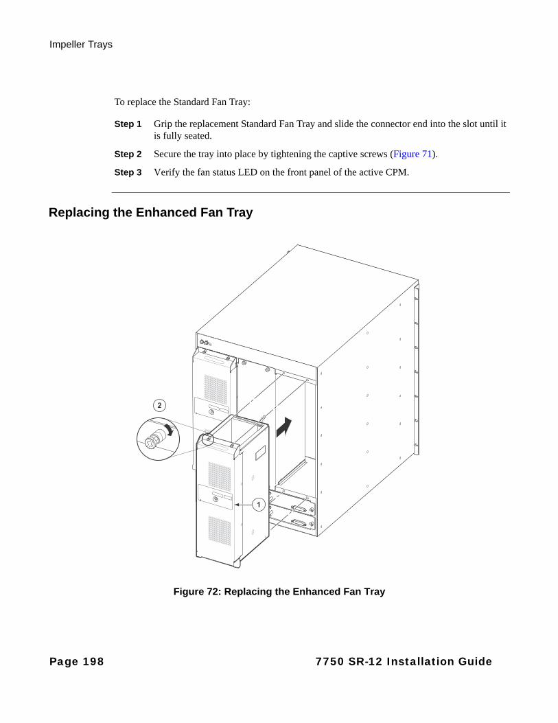
Impeller Trays
To replace the Standard Fan Tray:
Step 1 Grip the replacement Standard Fan Tray and slide the connector end into the slot until it is fully seated.
Step 2 Secure the tray into place by tightening the captive screws (Figure 71).
Step 3 Verify the fan status LED on the front panel of the active CPM.
Replacing the Enhanced Fan Tray
Figure 72: Replacing the Enhanced Fan Tray
1
2
Page 198 7750 SR-12 Installation Guide
Field Replaceable Units
To replace the Enhanced Fan Tray:
Step 1 Grip the replacement Enhanced Fan Tray and slide the connector end into the slot until it is fully seated.
Step 2 Secure the tray into place by tightening the captive screws (Figure 72).
Step 3 Verify the fan status LED on the front panel of the active CPM.
7750 SR-12 Installation Guide Page 199
Impeller Trays
Page 200 7750 SR-12 Installation Guide
Appendix C: Pinout Assignments
In This Chapter
This chapter provides information about standard cable pin assignments.
Topics in this chapter include:
• SF/CPM Port Types on page 202
• Cable Pin Assignments on page 204
→ BITS Port - RJ-48C Female on page 204
→ Console Port - DTE Mode - DB-9 Male on page 204
→ Console Port - DCE Mode - DB-9 Male on page 205
→ Alarm Port - DB-9 Female on page 205
→ 10/100 Management Ethernet Port - RJ-45 Female on page 206
→ AC Status Cable on page 206
7750 SR-12 Installation Guide Page 201
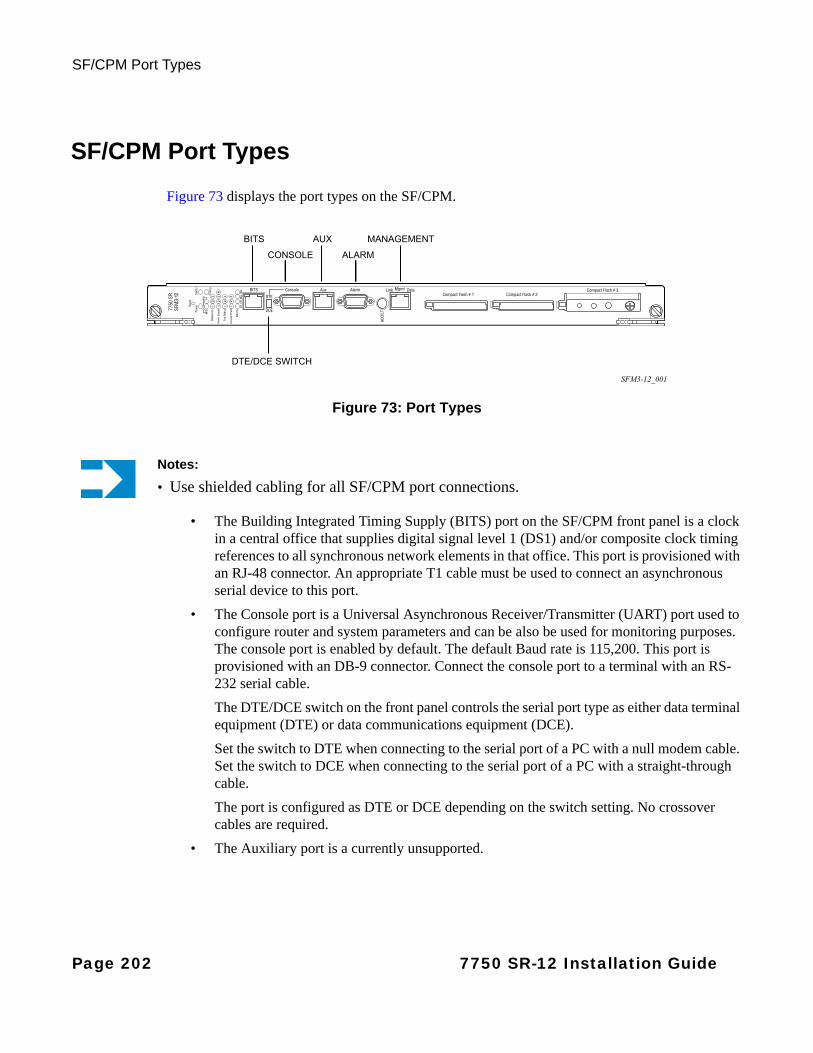
SF/CPM Port Types
SF/CPM Port Types
Figure 73 displays the port types on the SF/CPM.
Figure 73: Port Types
• The Building Integrated Timing Supply (BITS) port on the SF/CPM front panel is a clock in a central office that supplies digital signal level 1 (DS1) and/or composite clock timing references to all synchronous network elements in that office. This port is provisioned with an RJ-48 connector. An appropriate T1 cable must be used to connect an asynchronous serial device to this port.
• The Console port is a Universal Asynchronous Receiver/Transmitter (UART) port used to configure router and system parameters and can be also be used for monitoring purposes. The console port is enabled by default. The default Baud rate is 115,200. This port is provisioned with an DB-9 connector. Connect the console port to a terminal with an RS-232 serial cable.
The DTE/DCE switch on the front panel controls the serial port type as either data terminal equipment (DTE) or data communications equipment (DCE).
Set the switch to DTE when connecting to the serial port of a PC with a null modem cable. Set the switch to DCE when connecting to the serial port of a PC with a straight-through cable.
The port is configured as DTE or DCE depending on the switch setting. No crossover cables are required.
• The Auxiliary port is a currently unsupported.
Notes:
• Use shielded cabling for all SF/CPM port connections.
SFM3-12_001
BITS
CONSOLE
AUX
ALARM
MANAGEMENT
DTE/DCE SWITCH
Page 202 7750 SR-12 Installation Guide

Pinout Assignments
• The Alarm port is provisioned as a DB-9 serial port and is used to connect to external alarm devices that report conditions that trigger red or amber alarms. You must provide an appropriate cable configured according to the your alarm panel.
• The Management port is a 10/100 Ethernet port which is a channel to download images and manage the system. This port is provisioned with an RJ-45 jack on the front panel. You must provide a CAT5 Ethernet cable to connect to the port.
7750 SR-12 Installation Guide Page 203

Cable Pin Assignments
Cable Pin Assignments
Table 52 specifies the RJ-48 timing BITS (Building Integrated Timing Supply) clock connector pinouts.
Table 53 displays the DB-9 DTE mode Console port pin assignments. Use these pin assignments when the DTE/DCE switch on the SF/CPM front panel is set to DTE.
Table 52: BITS Port - RJ-48C Female
Pin Signal Direction Description
1 RXRING Input Receive Ring Signal
2 RXTIP Input Receive Tip Signal
3 NC - Not connected
4 TXRING Output Transmit Ring Signal
5 TXTIP Output Transmit Tip Signal
6 NC - Not connected
7 NC - Not connected
8 NC - Not connected
Table 53: Console Port - DTE Mode - DB-9 Male
Pin Signal Direction Description
1 DCD Input Data carrier detect
2 RXD Input Receive data
3 TXD Output Transmit data
4 DTR Output Data terminal ready
5 GND Signal ground Signal ground
6 DSR Input Data set ready
7 RTS Output Request to send
8 CTS Input Clear to send
9 RI Input Ring indicator
Page 204 7750 SR-12 Installation Guide
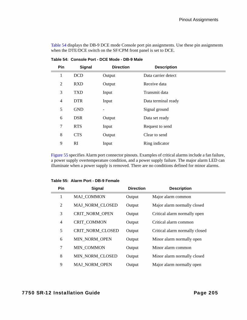
Pinout Assignments
Table 54 displays the DB-9 DCE mode Console port pin assignments. Use these pin assignments when the DTE/DCE switch on the SF/CPM front panel is set to DCE.
Figure 55 specifies Alarm port connector pinouts. Examples of critical alarms include a fan failure, a power supply overtemperature condition, and a power supply failure. The major alarm LED can illuminate when a power supply is removed. There are no conditions defined for minor alarms.
Table 54: Console Port - DCE Mode - DB-9 Male
Pin Signal Direction Description
1 DCD Output Data carrier detect
2 RXD Output Receive data
3 TXD Input Transmit data
4 DTR Input Data terminal ready
5 GND - Signal ground
6 DSR Output Data set ready
7 RTS Input Request to send
8 CTS Output Clear to send
9 RI Input Ring indicator
Table 55: Alarm Port - DB-9 Female
Pin Signal Direction Description
1 MAJ_COMMON Output Major alarm common
2 MAJ_NORM_CLOSED Output Major alarm normally closed
3 CRIT_NORM_OPEN Output Critical alarm normally open
4 CRIT_COMMON Output Critical alarm common
5 CRIT_NORM_CLOSED Output Critical alarm normally closed
6 MIN_NORM_OPEN Output Minor alarm normally open
7 MIN_COMMON Output Minor alarm common
8 MIN_NORM_CLOSED Output Minor alarm normally closed
9 MAJ_NORM_OPEN Output Major alarm normally open
7750 SR-12 Installation Guide Page 205
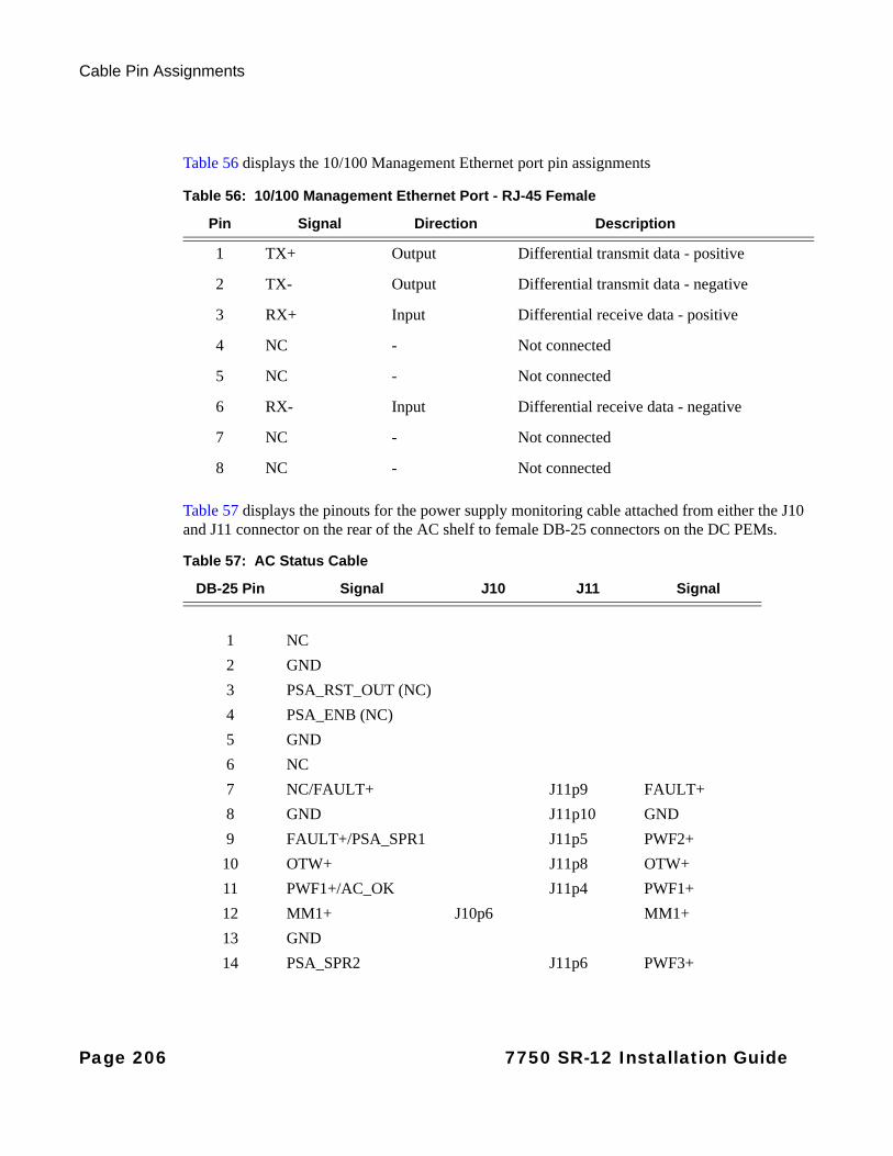
Cable Pin Assignments
Table 56 displays the 10/100 Management Ethernet port pin assignments
Table 57 displays the pinouts for the power supply monitoring cable attached from either the J10 and J11 connector on the rear of the AC shelf to female DB-25 connectors on the DC PEMs.
Table 56: 10/100 Management Ethernet Port - RJ-45 Female
Pin Signal Direction Description
1 TX+ Output Differential transmit data - positive
2 TX- Output Differential transmit data - negative
3 RX+ Input Differential receive data - positive
4 NC - Not connected
5 NC - Not connected
6 RX- Input Differential receive data - negative
7 NC - Not connected
8 NC - Not connected
Table 57: AC Status Cable
DB-25 Pin Signal J10 J11 Signal
1 NC
2 GND
3 PSA_RST_OUT (NC)
4 PSA_ENB (NC)
5 GND
6 NC
7 NC/FAULT+ J11p9 FAULT+
8 GND J11p10 GND
9 FAULT+/PSA_SPR1 J11p5 PWF2+
10 OTW+ J11p8 OTW+
11 PWF1+/AC_OK J11p4 PWF1+
12 MM1+ J10p6 MM1+
13 GND
14 PSA_SPR2 J11p6 PWF3+
Page 206 7750 SR-12 Installation Guide
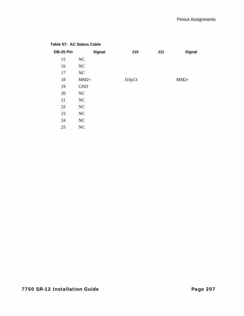
Pinout Assignments
15 NC
16 NC
17 NC
18 MM2+ J10p13 MM2+
19 GND
20 NC
21 NC
22 NC
23 NC
24 NC
25 NC
Table 57: AC Status Cable
DB-25 Pin Signal J10 J11 Signal
7750 SR-12 Installation Guide Page 207

Cable Pin Assignments
Page 208 7750 SR-12 Installation Guide
INDEX
AAC power
AC power rectifiers 113connecting cables to 100 Amp DC PEM 115connecting cables to 175 Amp DC PEM-3 114status 118
air filtersremoving 161, 162replacing 163
air flowdescription 60
Ccable
ground wire 74preparing DC cable 94
cable management systemdescription 34installing 70
cablingdescription 59
compact flash 126
configuringIOM 136MDA 137
connectionsconsole 130Telnet 132
DDC power
input terminal block wiring 97, 104lug specs 94, 102safety cover 97, 104wiring 102
Eempty slots 34
impedence panels 172
equipment rackdescription 56
FField Replaceable Unit (FRU)
disconnecting power cablesprocedures 189
removingPEMs
procedures 182, 185
Ggrounding 73, 75
description 58ground connection 73, 75preparing the ground wire 74procedure 73
IIMMs
description 27installing 139modifying configuration 169
impedance panelsdescription 34installing 172removing 147
impeller traysenhanced
removing 194installing 79removing and replacing 190replacing 197standard
removing 192
initializing the systemcompact flash 125procedure 127
IOMsconfiguring 136
7750 SR-12 Installation Guide Page 209
Index
description 26installing 139, 141modifying configuration 169removing 172replacing 173shutting down 169
IOMs and IMMsreplacing 173
LLEDs
AC power supply module 151M1-10GB-HS-XFP-B 156SF/CPM 22, 152status
compact flash 154fans 154power supply 153
MMDAs
changing configuration 175configuring 137installing 142removing 177replacing 178
Ppin assignments
alarm port 205BITS port 204console port (DCE) 205console port (DTE) 204management port 206status cable 206
power consumptioncalculation 45
power entry modulesSee power supply modules
power requirements 45, 48, 49
power supply modulesAC
disconnecting cables 187
disconnecting power cables (100 AMP DCPEM) 189
disconnecting power cables (175 AMP DCPEM-3) 188
installing 111LEDs 151monitoring 118
DCground connection 73ground wire 74terminal block wiring (100-Amp DC
PEMs) 104terminal block wiring (175-Amp DC PEM-
3) 97installing 88overview 28redundancy 28removing 179removing and replacing 179
Rrack
clearance 57clearance requirements 57mounting 67required tools for installation 56
Ssafety considerations
fans 60filters 60power 59
SF/CPMsinstalling 122removing 165replacing 166, 167
specificationschassis 40components 54electrical 42environmental 40MDA and MDA-XP 44power modules 41, 43
Page 210 7750 SR-12 Installation Guide
Index
statuscable connections 118
storing components 60
system specifications 40chassis 40
environmental 40power 41
Uunpacking 64
7750 SR-12 Installation Guide Page 211
Index
Page 212 7750 SR-12 Installation Guide