92783sl.pdf reelmaster 216/216-d (rev b) 1996
DESCRIPTION
92783sl.pdf Reelmaster 216/216-D (Rev B) 1996 サービスマニュアルTRANSCRIPT

Service Manual
Reelmas ter ® 216/216-D
Preface
This publication provides the service technician withinformation for troubleshooting, testing, and repair ofmajor systems and components on the Reelmaster 216and Reelmaster 216-D
REFER TO THE REELMASTER 216 OR 216-DOPERATOR’S MANUAL FOR OPERATING, MAIN-TENANCE AND ADJUSTMENT INSTRUCTIONS.Space is provided at the end of Chapter 2 in this publi-cation to insert the Operator’s Manuals and PartsCatalogs for your machine. Replacement Operator’sManuals are available by sending complete Model andSerial Number of traction unit and cutting unit to:
The Toro Company8111 Lyndale Avenue SouthMinneapolis, MN 55420
The Toro Company reserves the right to change productspecifications or this publication without notice.
This safety symb ol means DANGER, WARN-ING, or CAUT ION, PERSONAL SAFETY IN-STRUCTION. When you see this sy mbo l,carefully read the instructi ons that follow.Failure to obey the instructi ons may resu lt inpers onal i njur y.
NOTE: A NOTE will give general information about thecorrect operation, maintenance, service, testing orrepair of the machine.
IMPORTANT: The IMPORTANT not ice will give im-portant in structions which must be fo llowed topreve nt damage to systems or compo nents on themach ine.
© The Toro Company - 1991, 1994, 1996
Part No. 92783SL, Rev. B
Reelmaster 216-DReelmaster 216

This page is blank.

Table Of Contents
Chapter 1 - Safety
Safety Instructions . . . . . . . . . . . . . . . . . . . . . . . . 1 - 1
Chapter 2 - Product Records and Manuals
Product Records. . . . . . . . . . . . . . . . . . . . . . . . . . 2 - 1Equivalents and Conversions . . . . . . . . . . . . . . . . 2 - 2Torque Specifications . . . . . . . . . . . . . . . . . . . . . . 2 - 3Maintenance Interval Charts. . . . . . . . . . . . . . . . . 2 - 4Equipment Operational and Service Historical Report Record
Chapter 3 - Kohler Gas Engine
Specifications . . . . . . . . . . . . . . . . . . . . . . . . . . . . 3 - 1Adjustments . . . . . . . . . . . . . . . . . . . . . . . . . . . . . 3 - 2KOHLER MAGNUM ENGINE SERVICE MANUAL
Chapter 4 - Perkins Diesel Engine
Specifications . . . . . . . . . . . . . . . . . . . . . . . . . . . . 4 - 1General Information . . . . . . . . . . . . . . . . . . . . . . . 4 - 2Adjustments . . . . . . . . . . . . . . . . . . . . . . . . . . . . . 4 - 3PERKINS 100 SERIES WORKSHOP MANUAL
Chapter 5 - Hydraulic System
Specifications . . . . . . . . . . . . . . . . . . . . . . . . . . . . 5 - 2General Information . . . . . . . . . . . . . . . . . . . . . . . 5 - 3Hydraulic Schematics . . . . . . . . . . . . . . . . . . . . . . 5 - 6Special Tools. . . . . . . . . . . . . . . . . . . . . . . . . . . . 5 - 10Troubleshooting . . . . . . . . . . . . . . . . . . . . . . . . . 5 - 13
Testing . . . . . . . . . . . . . . . . . . . . . . . . . . . . . . . . 5 - 17Adjustments . . . . . . . . . . . . . . . . . . . . . . . . . . . . 5 - 24Repairs . . . . . . . . . . . . . . . . . . . . . . . . . . . . . . . . 5 - 29
Chapter 6 - Electrical System
Wiring Schematics . . . . . . . . . . . . . . . . . . . . . . . . 6 - 2Special Tools. . . . . . . . . . . . . . . . . . . . . . . . . . . . . 6 - 6Troubleshooting (Reelmaster 216) . . . . . . . . . . . . . . . 6 - 8Troubleshooting (Reelmaster 216-D) . . . . . . . . . . . . 6 - 14Testing . . . . . . . . . . . . . . . . . . . . . . . . . . . . . . . . 6 - 20Repairs . . . . . . . . . . . . . . . . . . . . . . . . . . . . . . . . 6 - 31
Chapter 7 - Wheels, Brakes and Steering
Specifications . . . . . . . . . . . . . . . . . . . . . . . . . . . . 7 - 2Adjustments . . . . . . . . . . . . . . . . . . . . . . . . . . . . . 7 - 3Repairs . . . . . . . . . . . . . . . . . . . . . . . . . . . . . . . . . 7 - 6
Chapter 8 - Cutting Unit Drive System
Adjustments . . . . . . . . . . . . . . . . . . . . . . . . . . . . . 8 - 2Repairs . . . . . . . . . . . . . . . . . . . . . . . . . . . . . . . . . 8 - 4
Chapter 9 - Cutting Units
Specifications . . . . . . . . . . . . . . . . . . . . . . . . . . . . 9 - 2Special Tools. . . . . . . . . . . . . . . . . . . . . . . . . . . . . 9 - 3Troubleshooting . . . . . . . . . . . . . . . . . . . . . . . . . . 9 - 4Set-up and Adjustments . . . . . . . . . . . . . . . . . . . . 9 - 6Service and Repairs . . . . . . . . . . . . . . . . . . . . . . 9 - 12
Reelmaster® 216/216-D

This page is blank.

Chapter 1
Safety
Table of Contents
SAFETY INSTRUCTIONS . . . . . . . . . . . . . . . . . . . . 1Before Operating. . . . . . . . . . . . . . . . . . . . . . . . . 1While Operating. . . . . . . . . . . . . . . . . . . . . . . . . . 2
While Doing Maintenance, Troubleshooting,Testing, Adjustments or Repairs . . . . . . . . . . . . . 3
Safety Instructions
The Reelmaster 216/216-D has been tested and veri-fied for compliance with the B71.4-1984 specificationsof the American National Standards Institute (ANSI) forriding mowers when equipped with rear ballast (seeOperator’s Manual). Although hazard control and acci-dent prevention are partially dependent upon the designand configuration of the machine, these factors are alsodependent upon the awareness, concern, and propertraining of the personnel involved in the operation, trans-port maintenance, and storage of the machine. Im-proper use or maintenance of the machine can result ininjury or death.
Obey the following safety instructions. Readand understand these instructions before op-erating the Reelmaster 216/216-D or doingmaintenance, troubleshooting, testing, ad-justments or repairs. Failure to comply withthe safety instructions may result in personalinjury.
Before Operating
1. Read and understand the Operator’s Manual beforestarting, operating, maintaining or repairing the ma-chine. Become familiar with the controls and know howto stop the machine and engine quickly. ReplacementOperator’s Manuals are available by sending completeModel and Serial Number of traction unit and cuttingunits to:
The Toro Company8111 Lyndale Avenue SouthMinneapolis, MN 55420
Use the Model and Serial Number when referring to yourmachine. If you have questions about this Service Infor-mation, please contact:
The Toro CompanyCommercial Service Department8111 Lyndale Avenue SouthMinneapolis, MN 55420
2. Never allow children to operate the machine or adultsto operate it without proper instruction. Only trainedoperators who have read this manual should operatethis machine.
3. Become familiar with the controls and know how tostop the machine and engine quickly.
4. Never operate the machine while under the influenceof drugs or alcohol.
5. Keep all shields, safety devices and decals in place.If a shield, safety device or decal is defective or dam-aged, repair or replace it before operating the machine.
6. Always wear substantial shoes. Do not operate ma-chine wearing sandals, tennis shoes, sneakers or whenbarefoot. Do not wear loose fitting clothing that could getcaught in moving parts and possibly cause personalinjury. Wearing safety glasses, safety shoes, long pantsand a helmet is advisable and required by some localordinances and insurance regulations.
CAUTION
Reelmaster® 216/216-D Page 1 - 1 Safety Instructions

7. Make sure interlock switches are adjusted correctlyso engine cannot be started unless traction pedal is inNEUTRAL and cutting units are DISENGAGED.
8. Remove all debris or other objects that might bepicked up and thrown by the reels or fast moving com-ponents from other attached implements. Keep all by-standers away from operating area.
9. Since gasoline and diesel fuel is flammable, handleit carefully:
A. Use an approved fuel container.B. Do not remove fuel tank cap while engine is hotor running.C. Do not smoke while handling fuel.D. Fill fuel tank outdoors and only to within an inch(25 mm) from the top of the tank, not the filler neck.Do not overfill.E. Wipe up any spilled fuel.
While Operating
10. Sit on the seat when starting and operating themachine.
11. Before starting the engine:
A. Engage the parking brake.B. Make sure traction pedal is in NEUTRAL andcutting units are DISENGAGED.C. After engine is started, release parking brake andkeep foot off traction pedal. Machine must not move.If movement is evident, the neutral return mecha-nism is adjusted incorrectly; therefore, shut engineoff and adjust until machine does not move whentraction pedal is released.
12. Seating capacity is one person. Never carry passen-gers.
13. Do not run engine in a confined area without ade-quate ventilation. Exhaust fumes are hazardous andcould possibly be deadly.
14. Check interlock switches daily for proper operation.If a switch fails, replace it before operating the machine.Replace all four interlock switches in wiring systemevery two years, regardless if they are working properlyor not..
15. Using the machine demands attention. To preventloss of control:
A. Operate only in daylight, or when there is goodartificial light.B. Drive slowly.C. Watch for holes or other hidden hazards.D. Look behind machine before backing up.E. Do not drive close to a sand trap, ditch, creek orother hazard.F. Reduce speed when making sharp turns andturning on a hillside.G. Avoid sudden stops and starts.
16. Keep hands, feet and clothing away from movingparts and reel discharge area. If so equipped, grassbaskets must be in place during operation of reels formaximum safety.
17. Traverse slopes carefully. Do not start or stop sud-denly when traveling uphill or downhill.
18. Operator must be skilled and trained in how to driveon hillsides. Failure to use caution on slopes or hills maycause loss of control and vehicle to tip or roll, possiblyresulting in personal injury or death.
19. If engine stalls or wheels loose traction and cannotmake it to the top of a slope, do not turn machine around.Always back slowly straight down the slope.
20. Raise cutting units before driving from one work areato another.
21. DON’T TAKE AN INJURY RISK! When a person orpet appears unexpectedly in or near the mowing area,STOP MOWING. Careless operation, combined withterrain angles, ricochets, or improperly positionedguards can lead to thrown object injuries. Do not resumemowing until area is cleared.
22. Do not touch engine, muffler or exhaust pipe whileengine is running or soon after it is stopped. These areascould be hot enough to cause burns.
23. If cutting unit strikes a solid object or vibrates abnor-mally, stop immediately, turn engine off, set parkingbrake and wait for all motion to stop. Inspect for damage.If reel or bedknife is damaged, repair or replace it beforeoperating.
24. Before getting off of the seat:
A. Move traction pedal to neutral.B. Set parking brake.C. Disengage cutting units and wait for reels to stop.D. Stop engine and remove key from switch.
Safety Instructions Page 1 - 2 Reelmaster® 216/216-D

While Doing Maintenance, Troubleshooting, Testing, Adjustments or Repairs
25. Before servicing or making any adjustments, stopengine and remove key from switch.
26. Make sure machine is in safe operating condition bykeeping all nuts, bolts and screws tight.
27. Make sure all hydraulic line connections are tight,and all hydraulic hoses and lines are in good conditionbefore applying pressure to the system.
28. Keep body and hands away from pin hole leaks ornozzles that eject high pressure hydraulic fluid. Usecardboard or paper to find hydraulic leaks. Hydraulicfluid escaping under pressure can penetrate skin andcause injury. Fluid accidentally injected into the skinmust be surgically removed within a few hours by adoctor familiar with this form of injury or gangrene mayresult.
29. Before disconnecting or performing any work on thehydraulic system, all pressure in system must be re-lieved by lowering cutting units to the ground and stop-ping the engine.
30. To reduce potential fire hazard, keep engine areafree of excessive grease, grass, leaves and dirt.
31. If engine must be running to perform maintenanceor an adjustment, keep hands, feet, clothing and otherparts of the body away from cutting units and othermoving parts. Keep all bystanders away.
32. Do not overspeed engine by changing governorsetting. To assure safety and accuracy, have an Author-ized Toro Distributor check maximum engine speed.
33. Shut engine off before checking or adding oil toengine crankcase.
34. Disconnect battery before checking or adding oil tothe crankcase.
35. At the time of manufacture, the machine conformedto the safety standards for riding mowers. To assureoptimum performance and continued safety certificationof the machine, use genuine Toro replacement parts andaccessories. Replacement parts and accessories madeby other manufacturers may result in non-conformancewith the safety standards, and the warranty may bevoided.
Reelmaster® 216/216-D Page 1 - 3 Safety Instructions

Safety Instructions Page 1 - 4 Reelmaster® 216/216-D
Chapter 2
Product Records and Manuals
Table of Contents
PRODUCT RECORD FORM . . . . . . . . . . . . . . . . . . 1EQUIVALENTS AND CONVERSIONS . . . . . . . . . . 2
Decimal and Millimeter Equivalents . . . . . . . . . . 2U.S. to Metric Conversions . . . . . . . . . . . . . . . . . 2
TORQUE SPECIFICATIONS . . . . . . . . . . . . . . . . . . 3Capscrew Markings and Torque Values - U.S. . . 3Capscrew Markings and Torque Values - Metric . 3
MAINTENANCE CHARTS . . . . . . . . . . . . . . . . . . . . 4Reelmaster 216 . . . . . . . . . . . . . . . . . . . . . . . . . . 4Reelmaster 216-D . . . . . . . . . . . . . . . . . . . . . . . . 5
Product Records
Record information about your Reelmaster 216/216-Don the SERVICE HISTORY REPORT form. Use thisinformation when referring to your machine.
Insert the Operator’s Manuals and Parts Catalogs foryour Reelmaster 216/216-D at the end of this section.
Rev. BReelmaster® 216/216-D Page 2 - 1 Product Records

Equivalents and Conversions
Decimal and Millimeter Equivalents
U.S to Metric Conversions
Rev. A
___________________________________________________________________________________________________
Fractions Decimals mm Fractions Decimals mm___________________________________________________________________________________________________
1/64 0.015625 — 0.397 33/64 0.515625 — 13.0971/32 ––––– 0.03125 — 0.794 17/32 –––– 0.53125 — 13.494
3/64 0.046875 — 1.191 35/64 0.546875 — 13.8911/16 –––––––––––– 0.0625 — 1.588 9/16 –––––––––––– 0.5625 — 14.288
5/64 0.078125 — 1.984 37/64 0.578125 — 14.6843/32 ––––– 0.9375 — 2.381 19/32 –––– 0.59375 — 15.081
7/64 0.109275 — 2.778 39/64 0.609375 — 15.4781/8––––––––––––– 0.1250 — 3.175 5/8 ––––––––––––– 0.6250 — 15.875
9/64 0.140625 — 3.572 41/64 0.640625 — 16.2725/32 ––––– 0.15625 — 3.969 21/32 –––– 0.65625 — 16.669
11/64 0.171875 — 4.366 43/64 0.671875 — 17.0663/16 –––––––––––– 0.1875 — 4.762 11/16 ––––––––––– 0.6875 — 17.462
13/64 0.203125 — 5.159 45/64 0.703125 — 17.8597/32 ––––– 0.21875 — 5.556 23/32 –––– 0.71875 — 18.256
15/64 0.234375 — 5.953 47/64 0.734375 — 18.6531/4––––––––––––– 0.2500 — 6.350 3/4 ––––––––––––– 0.7500 — 19.050
17/64 0.265625 — 6.747 49/64 0.765625 — 19.4479/32 ––––– 0.28125 — 7.144 25/32 –––– 0.78125 — 19.844
19/64 0.296875 — 7.541 51/64 0.796875 — 20.2415/16 –––––––––––– 0.3125 — 7.938 13/16 ––––––––––– 0.8125 — 20.638
21/64 0.328125 — 8.334 53/64 0.828125 — 21.03411/32 –––– 0.34375 — 8.731 27/32 –––– 0.84375 — 21.431
23/64 0.359375 — 9.128 55/64 0.859375 — 21.8283/8––––––––––––– 0.3750 — 9.525 7/8 ––––––––––––– 0.8750 — 22.225
25/64 0.390625 — 9.922 57/64 0.890625 — 22.62213/32 –––– 0.40625 — 10.319 29/32 –––– 0.90625 — 23.019
27/64 0.421875 — 10.716 59/64 0.921875 — 23.4167/16 –––––––––––– 0.4375 — 11.112 15/16 ––––––––––– 0.9375 — 23.812
29/64 0.453125 — 11.509 61/64 0.953125 — 24.20915/32 –––– 0.46875 — 11.906 31/32 –––– 0.96875 — 24.606
31/64 0.484375 — 12.303 63/64 0.984375 — 25.0031/2––––––––––––– 0.5000 — 12.700 1 –––––––––––––– 1.000 — 25.400
1 mm = 0.03937 in. 0.001 in. = 0.0254 mm___________________________________________________________________________________________________
___________________________________________________________________________________________________
To Convert Into Multiply By___________________________________________________________________________________________________
Linear Miles Kilometers 1.609Measurement Yards Meters 0.9144
Feet Meters 0.3048Feet Centimeters 30.48Inches Meters 0.0254Inches Centimeters 2.54Inches Millimeters 25.4
___________________________________________________________________________________________________
Area Square Miles Square Kilometers 2.59Square Feet Square Meters 0.0929Square Inches Square Centimeters 6.452Acre Hectare 0.4047
___________________________________________________________________________________________________
Volume Cubic Yards Cubic Meters 0.7646Cubic Feet Cubic Meters 0.02832Cubic Inches Cubic Centimeters 16.39
___________________________________________________________________________________________________
Weight Tons (Short) Metric Tons 0.9078Pounds Kilograms 0.4536Ounces (Avdp.) Grams 28.3495
___________________________________________________________________________________________________
Pressure Pounds/Sq. In. Kilopascal 6.895___________________________________________________________________________________________________
Work Foot-pounds Newton-Meters 1.356Foot-pounds Kilogram-Meters 0.1383Inch-pounds Kilogram-Centimeters 1.152144
___________________________________________________________________________________________________
Liquid Volume Quarts Liters 0.9463Gallons Liters 3.785
___________________________________________________________________________________________________
Liquid Flow Gallons/Minute Liters/Minute 3.785___________________________________________________________________________________________________
Temperature Fahrenheit Celsius 1. Subract 32o
2. Multiply by 5/9___________________________________________________________________________________________________
Equivalents and Conversions Page 2 - 2 Reelmaster® 216/216-D

Torque Specifications
Use these torque values when specific torque valuesare not given. DO NOT use these values in place ofspecified values.
The torque values listed below are for lubricatedthreads. Plated threads are considered to be lubricated.
Capscrew Markings and Torque Values - U.S. Customary
Capscrew Markings and Torque Values – Metric
SAE Grade Number 5 8________________________________________________________________________________________________________________________________________________________
Capscrew Head Markings
________________________________________________________________________________________________________________________________________________________
Capscrew Torque - Grade 5 Capscrew Torque - Grade 8Capscrew Body Size Cast Iron Aluminum Cast Iron Aluminum
ft-lb Nm ft-lb Nm ft-lb Nm ft-lb Nm________________________________________________________________________________________________________________________________________________________
1/4-20 7 9 6 8 11 15 9 12-28 9 12 7 9 13 18 10 14
________________________________________________________________________________________________________________________________________________________
5/16-18 15 20 12 16 22 30 18 24-24 17 23 14 19 24 33 19 25
________________________________________________________________________________________________________________________________________________________
3/8-16 30 40 20 25 40 55 30 40-24 30 40 25 35 45 60 35 45
________________________________________________________________________________________________________________________________________________________
7/16-14 45 60 35 45 65 90 50 65-20 50 65 40 55 70 95 55 75
________________________________________________________________________________________________________________________________________________________
1/2-13 70 95 55 75 95 130 75 100-20 75 100 60 80 110 150 90 120
________________________________________________________________________________________________________________________________________________________
9/16-12 100 135 80 110 140 190 110 150-18 110 150 85 115 155 210 125 170
________________________________________________________________________________________________________________________________________________________
5/8-11 135 180 110 150 190 255 150 205-18 155 210 120 160 215 290 170 230
________________________________________________________________________________________________________________________________________________________
3/4-10 240 325 190 255 340 460 270 365-16 270 365 210 285 380 515 300 410
________________________________________________________________________________________________________________________________________________________
7/8-9 360 490 280 380 550 745 440 600-14 390 530 310 420 610 825 490 660
________________________________________________________________________________________________________________________________________________________
1-8 530 720 420 570 820 1100 660 890-14 590 800 480 650 890 1200 710 960
Commercial Steel Class 8.8 10.9 12.9________________________________________________________________________________________________________________________________________________________
Capscrew Head Markings
________________________________________________________________________________________________________________________________________________________
Thread Capscrew Torque - Class 8.8 Capscrew Torque - Class 10.9 Capscrew Torque - Class 12.9Diameter Cast Iron Aluminum Cast Iron Aluminum Cast Iron Aluminum
mm ft-lb Nm ft-lb Nm ft-lb Nm ft-lb Nm ft-lb Nm ft-lb Nm________________________________________________________________________________________________________________________________________________________
6 5 9 4 7 9 14 7 11 9 14 7 11________________________________________________________________________________________________________________________________________________________
7 9 14 7 11 14 18 11 14 18 23 14 18________________________________________________________________________________________________________________________________________________________
8 18 25 14 18 23 32 18 25 27 36 21 28________________________________________________________________________________________________________________________________________________________
10 30 40 25 30 45 60 35 45 50 70 40 55________________________________________________________________________________________________________________________________________________________
12 55 70 40 55 75 105 60 80 95 125 75 100________________________________________________________________________________________________________________________________________________________
14 85 115 65 90 120 160 95 125 145 195 110 150________________________________________________________________________________________________________________________________________________________
16 130 180 100 140 175 240 135 190 210 290 165 220________________________________________________________________________________________________________________________________________________________
18 170 230 135 180 240 320 185 250 290 400 230 310
Reelmaster® 216/216-D Page 2 - 3 Torque Specifications

Rev. BTorque Specifications Page 2 - 4 Reelmaster® 216/216-D

EQUIPMENT OPERATION AND SERVICE HISTORY REPORTfor
REELMASTER® 216
TORO Model and Serial Number:__________-__________
Engine Numbers: ____________________
Transmission Numbers: ____________________
Date Purchased: ____________________ Warranty Expires __________
Purchased From: ____________________
____________________
____________________
Contacts: Parts ____________________ Phone__________________
Service ____________________ Phone__________________
Sales ____________________ Phone__________________
See your TORO Distributor/Dealer for other Publications, Manuals, and Videos from The TORO Company.

REELMASTER® 216 Maintenance Schedule
Minimum Recommended Maintenance Intervals: Maintenance Procedure Maintenance Interval & Service
Every400hrs
Every200hrs
Every100hrs
Every50hrs
Check Battery Fluid/Connections Every25hrs
A LevelService
Lubricate Grease Fittings
Service Air Filter Pre-Cleaner
† Change Engine Oil
† Check Traction Belt Tension B LevelServiceService Air Filter Paper Element
Service Spark Plug C LevelService† Torque Wheel Lug Nuts
† Replace Hydraulic Filter
Adjust Electric Clutch D LevelServiceInspect Traction Linkage Movement
Change Hydraulic Fluid
Decarbon Combustion Chamber
Adjust Valves and Torque Head Bolts E LevelService‡ Check Engine RPM (idle and full throttle)
† Initial break in at 5 hours
‡ Initial break in at 50 hours
Replace Moving HosesAnnual Recommendations:
Items listed are recommended every 1000hours or 2 years whichever occurs first.
Replace Safety Switches
Fuel Tank - Drain/Flush
Replace Fuel Filter
Hydraulic Tank - Drain/Flush
(See Operator's and Service Manual for specifications and procedures)

REELMASTER® 216 Daily Maintenance Check List
Unit Designation: __________Daily Maintenance: (duplicate this page for routine use) TORO ID#:_______-_______
Daily Maintenance Check For Week Of_____________
Maintenance Check ItemMON
_______HRS
TUES_______HRS
WED_______HRS
THURS_______HRS
FRI_______HRS
SAT_______HRS
SUN_______HRS
Safety Interlock Operation
Brake Operation
Engine Oil Level
Air Filter Pre-Cleaner
Clean Engine Cooling Fins
Unusual Engine Noises
Unusual Operating Noises
Hydraulic System Oil Level
Hydraulic Hoses for Damage
Fluid Leaks
Fuel Level
Tire Pressure
Instrument Operation
Reel-to-Bedknife Adjustment
Height-of-Cut Adjustment
Cutting Unit Belt Adjustment
Lubricate All Grease Fittings1
Touch-up damaged paint1 = Immediately after every washing, regardless of the interval listed.
Notation for areas of concern: Inspection performed by:________________Item Date Information
1234567
(See Operator's and Service Manual for specifications and procedures)

REELMASTER® 216 Supervisor Maintenance Work Order Date:______________
(duplicate this page for routine use) Unit Designation: TORO I.D. #: Remarks:
____________-____________Hours: Service to perform (circle):
A B C D E OtherTechnician:
A -Service (every 25 hours) B -Service (every 50 hours) C -Service (every 100 hours)
Check Battery Fluid/Connections Check Traction Belt Tension Service Spark Plug
Lubricate Grease Fittings Service Air Filter Paper Element Torque Wheel Lug Nuts
Service Air Filter Pre-Cleaner A-Service required A and B Service required
Change Engine Oil _______________________________ _______________________________
______________________________ _______________________________ _______________________________
______________________________ _______________________________ _______________________________
______________________________ _______________________________ _______________________________
______________________________ _______________________________ _______________________________
______________________________ _______________________________ _______________________________
D -Service (every 200 hours) E - Service (every 400 hours) Other - Annual Service and Specials
Replace Hydraulic Filter Change Hydraulic Fluid Replace Moving Hoses
Adjust Electric Clutch Decarbon Combustion Chamber Replace Safety Switches
Inspect Traction Linkage Movement Adjust Valves and Torque Head Bolts Fuel Tank - Drain/Flush
A, B, and C Service required Check Engine RPM (idle & full throttle) Replace Fuel Filter
______________________________ A, B, C, and D Service required Hydraulic Tank - Drain/Flush
______________________________ _______________________________ _______________________________
______________________________ _______________________________ _______________________________
______________________________ _______________________________ _______________________________
______________________________ _______________________________ _______________________________
(See Operator's and Service Manual for specifications and procedures) Form No. 95-845-SL

EQUIPMENT OPERATION AND SERVICE HISTORY REPORTfor
REELMASTER® 216-D
TORO Model and Serial Number:__________-__________
Engine Numbers: ____________________
Transmission Numbers: ____________________
Date Purchased: ____________________ Warranty Expires__________
Purchased From: ____________________
____________________
____________________
Contacts: Parts ____________________ Phone__________________
Service ____________________ Phone__________________
Sales ____________________ Phone__________________
See your TORO Distributor/Dealer for other Publications, Manuals, and Videos from The TORO Company.

REELMASTER® 216-D Maintenance Schedule
Minimum Recommended Maintenance Intervals: Maintenance Procedure Maintenance Interval & Service
Every400hrs
Every200hrs
Every100hrs
Inspect Air Filter, Dust Cup, and Baffle Every50hrsLubricate All Grease Fittings
† Change Engine Oil A LevelService† Check Fan and Alternator Belt Tension
† Change Engine Oil Filter B LevelService† Check Traction Belt Tension
Service Air Filter
Replace Fuel Filter/Water Separator
† Replace Hydraulic Filter C LevelService† Torque Wheel Lug Nuts
Replace Hydraulic Fluid
Check Battery Level/Connections
Inspect Traction Linkage Movement
‡ Torque Head Bolts and Adjust Valves D LevelService‡ Check Engine RPM (idle and full throttle)
† Initial break in at 10 hours
‡ Initial break in at 50 hours
Replace Moving HosesAnnual Recommendations:
Items listed are recommended every1000 hours or 2 years whichever occurs
first.
Replace Safety Switches
Cooling System - Flush / Replace Fluid
Replace Thermostat
Fuel Tank - Drain/Flush
Hydraulic Tank - Drain/Flush
(See Operator's and Service Manual for specifications and procedures)
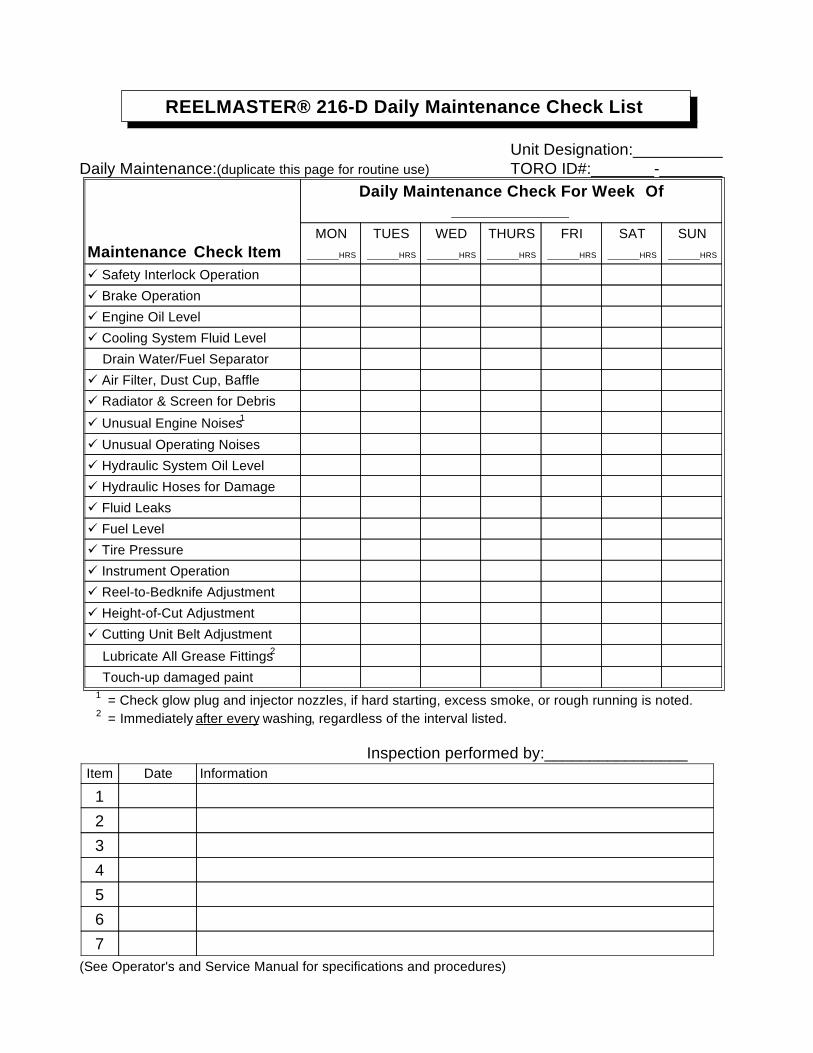
REELMASTER® 216-D Daily Maintenance Check List
Unit Designation:__________Daily Maintenance:(duplicate this page for routine use) TORO ID#:_______-_______
Daily Maintenance Check For Week Of_____________
Maintenance Check ItemMON
_______HRS
TUES_______HRS
WED_______HRS
THURS_______HRS
FRI_______HRS
SAT_______HRS
SUN_______HRS
Safety Interlock Operation
Brake Operation
Engine Oil Level
Cooling System Fluid Level
Drain Water/Fuel Separator
Air Filter, Dust Cup, Baffle
Radiator & Screen for Debris
Unusual Engine Noises1
Unusual Operating Noises
Hydraulic System Oil Level
Hydraulic Hoses for Damage
Fluid Leaks
Fuel Level
Tire Pressure
Instrument Operation
Reel-to-Bedknife Adjustment
Height-of-Cut Adjustment
Cutting Unit Belt Adjustment
Lubricate All Grease Fittings2
Touch-up damaged paint1 = Check glow plug and injector nozzles, if hard starting, excess smoke, or rough running is noted.2 = Immediately after every washing, regardless of the interval listed.
Inspection performed by:________________Item Date Information
1234567
(See Operator's and Service Manual for specifications and procedures)

REELMASTER® 216-D Supervisor Maintenance Work Order Date:______________
(duplicate this page for routine use) Unit Designation: TORO I.D. #: Remarks:
____________-____________Hours: Service to perform (circle):
A B C D OtherTechnician:
A -Service (every 50 hours) B -Service (every 100 hours) C -Service (every 200 hours)
Inspect Air Filter, Dust Cup, and Baffle Change Engine Oil Filter Service Air Filter
Lubricate All Grease Fittings Check Traction Belt Tension Replace Fuel Filter/Water Separator
Change Engine Oil A-Service required Replace Hydraulic Filter
Check Fan and Alternator Belt Tension ______________________________ Torque Wheel Lug Nuts
______________________________ ______________________________ A and B Service required
________________________________ ______________________________ _______________________________
________________________________ ______________________________ _______________________________
________________________________ ______________________________ _______________________________
________________________________ ______________________________ _______________________________
D -Service (every 400 hours) Other - Annual Service and Specials Additional Service ItemsReplace Hydraulic Fluid Replace Moving Hoses _______________________________
Check Battery Level/Connections Replace Safety Switches _______________________________
Inspect Traction Linkage Movement Cooling System - Flush/Replace Fluid _______________________________
Torque Head Bolts and Adjust Valves Replace Thermostat _______________________________
Check Engine RPM (Idle & Full Throttle) Fuel Tank - Drain/Flush _______________________________
A, B, and C Service required Hydraulic Tank - Drain/Flush _______________________________
_______________________________ ______________________________ _______________________________
________________________________ ______________________________ _______________________________
________________________________ ______________________________ _______________________________
(See Operator's and Service Manual for specifications and procedures) Form No. 95-846-SL

Chapter 3
Kohler Engine
Table of Contents
SPECIFICATIONS . . . . . . . . . . . . . . . . . . . . . . . . . . 1ADJUSTMENTS. . . . . . . . . . . . . . . . . . . . . . . . . . . . 2
Carburetor Adjustments. . . . . . . . . . . . . . . . . . . . 2KOHLER MAGNUM ENGINE SERVICE MANUAL
Specifications
Item Specification___________________________________________________________________________________________
Make/Designation Kohler M16SAir cooled, single cylinder, gasoline, horizontal shaft
________________________________________________________________________________________________________________________________________________________
Weight (approximate) 129 lb.________________________________________________________________________________________________________________________________________________________
Crankcase Oil Capacity 5.25 pints________________________________________________________________________________________________________________________________________________________
Oil API Classification SF or SG
Above +32° F (0° C) SAE 30W recommendedor SAE 10W-30 or 10W-40 as a substitute
Below +32° F (0° C) SAE 5W-20 or 5W-30 recommendedor SAE 10W-30 or 10W-40 as a substitute
________________________________________________________________________________________________________________________________________________________
Fuel Unleaded Regular Gasoline________________________________________________________________________________________________________________________________________________________
High RPM Setting (no load) 3600 ± 100 RPM ________________________________________________________________________________________________________________________________________________________
Low RPM Setting (no load) 1200 ± 100 RPM
Reelmaster® 216/216-D Page 3 - 1 Specifications

Adjustments
Carburetor Adjustments
Lack of power accompanied by black sooty exhaustsmoke is usually caused by a rich carburetor setting.Since a dirty air cleaner element causes the sameconditions, check it before adjusting carburetor.
High RPM Setting 3600 ± 100Low RPM Setting 1200 ± 100
IMPORTANT: Check to make sure the choke is op-erating correctly before the carburetor is adjusted.
1. Main fuel screw – Close screw by gently rotating itclockwise.
IMPORTANT: Do not close the screw too tight be-cause the screw will likely be damaged.
2. Rotate – open – the main fuel screw 3-1/2 turnscounterclockwise.
3. Idle fuel adjusting screw – Close screw by gentlyrotating it clockwise. Open screw by rotating it 2-1/2turns counterclockwise.
Engine must be running so final adjustmentof the carburetor can be performed. To guardagainst possible personal injury, keep hands,feet, face and other parts of the body awayfrom the muffler, other hot parts of the engine,and other moving or rotating parts of theengine. Assure reel switch is in DISENGAGEposition and cutting units are on the shopfloor. Also engage parking brake.
IMPORTANT: Do not close the screw too tightlybecause the screw will likely be damaged.
Note: These settings are approximate - however, thesettings will allow engine to be starter so carburetor canbe fine tuned – steps 4 - 7.
4. Start engine and let it run for 5 to 10 minutes at halfthrottle to warm up. Engine must be warm before mak-ing final adjustments.
5. Move throttle to TRANSPORT position. Turn mainfuel screw in until speed decreases and note position ofscrew. Now turn screw out – the engine speed may firstincrease, then it will decrease as screw is turned. Notethe position of screw when engine speed starts todecrease. Set the screw at the midpoint of the twopositions noted.
6. To adjust idle fuel adjusting screw, follow same pro-cedure as for main fuel but more throttle to IDLE after 5to 10 minute warm up and make adjustment.
7. Idle Speed Setting – Run engine at half-throttle for 5to 10 minutes to warm up. Move throttle to IDLE and setengine speed to 1200 RPM by turning the idle speedadjusting screw clockwise or counterclockwise.
Figure 2
1. Main fuel screw2. Idle fuel adjusting screw3. Idle speed screw
CAUTION
Adjustments Page 3 - 2 Reelmaster® 216/216-D
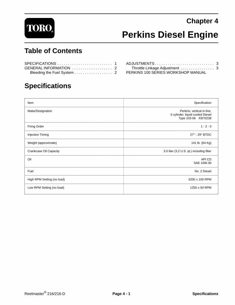
Chapter 4
Perkins Diesel Engine
Table of Contents
SPECIFICATIONS . . . . . . . . . . . . . . . . . . . . . . . . . . 1GENERAL INFORMATION . . . . . . . . . . . . . . . . . . . 2
Bleeding the Fuel System . . . . . . . . . . . . . . . . . . 2
ADJUSTMENTS . . . . . . . . . . . . . . . . . . . . . . . . . . . . 3Throttle Linkage Adjustment . . . . . . . . . . . . . . . . 3
PERKINS 100 SERIES WORKSHOP MANUAL
Specifications
Item Specification________________________________________________________________________________________________________________________________________________________
Make/Designation Perkins, vertical in-line,3 cylinder, liquid cooled Diesel
Type 103-06 KB70238________________________________________________________________________________________________________________________________________________________
Firing Order 1 - 2 - 3________________________________________________________________________________________________________________________________________________________
Injection Timing 27° - 29° BTDC________________________________________________________________________________________________________________________________________________________
Weight (approximate) 141 lb. (64 Kg)________________________________________________________________________________________________________________________________________________________
Crankcase Oil Capacity 3.0 liter (3.2 U.S. qt.) including filter________________________________________________________________________________________________________________________________________________________
Oil API CDSAE 10W-30
________________________________________________________________________________________________________________________________________________________
Fuel No. 2 Diesel________________________________________________________________________________________________________________________________________________________
High RPM Setting (no load) 3200 ± 100 RPM________________________________________________________________________________________________________________________________________________________
Low RPM Setting (no load) 1250 ± 50 RPM
Reelmaster® 216/216-D Page 4 - 1 Specifications

General Information
Bleeding The Fuel System (Fig. 1, 2)
Because diesel fuel is flammable, use cautionwhen storing or handling it. Do not smokewhile filling the fuel tank. Do not fill fuel tankwhile engine is running, hot or when machineis in an enclosed area. Always fill fuel tankoutside and wipe up any spilled diesel fuelbefore starting the engine. Store fuel in aclean, safety-approved container and keepcap in place. Use diesel fuel for the engineonly; not for any other purpose.
1. Park machine on a level surface. Make sure fuel tankis at least half full.
2. Unlatch and raise hood.
2. Open fuel shut-off valve under fuel tank and on fuelfilter.
3. Open two (2) bleed screws, on side of fuel filtermounting head, allowing bowl to re-fill with fuel. Closebleed screws when bowl is filled.
4. On left side of engine (below alternator) locate trans-fer pump inlet screw. Note angle of fitting on transferpump inlet and loosen screw (left screw only).
5. When a steady stream of fuel flows out of transferpump screw, tighten screw, retaining angle of fittingbefore loosening.
6. Loosen injection pump inlet screw on right side ofengine.
7. Pump priming lever until a steady stream of fuel flowsout of injector pump inlet screw, then tighten screw.
Figure 1
1. Fuel shut-off (behind engine)2. Bleed screws (2)3. Bowl
Figure 2
1. Transfer pump screw2. Injection pump inlet screw location3. Injection pump inlet screw4. Priming lever5. Note fitting angle
CAUTION
12
1
3
2
45
3
General Information Page 4 - 2 Reelmaster® 216/216-D

Adjustments
Throttle Linkage Adjustment
1. Adjust low engine speed to 1250 ± 50 RPM at engine.
2. With the engine off, adjust throttle stop on back sideof control panel so throttle lever on engine goes againstlow speed adjustment screw at the same time throttlelever on control panel bottoms out.
3. Adjust high engine speed to 3200 ± 100 RPM atengine.
4. With engine off, move throttle control lever on controlpanel up to high speed position. Loosen capscrew andnut securing throttle cable clamp near engine. Pull cabletoward frame until throttle lever on engine is up againsthigh speed adjustment screw. Tighten capscrew and nutsecuring throttle cable clamp.
5. Check to make sure throttle lever on engine goesagainst high speed adjustment screw when throttle oncontrol panel is moved up to high speed position. Whenthrottle lever on control panel is moved down to lowspeed position, throttle lever on engine should goagainst low speed adjustment screw at the same timethrottle lever on control panel bottoms out.
Reelmaster® 216/216-D Page 4 - 3 Adjustments

Adjustments Page 4 - 4 Reelmaster® 216/216-D
Chapter 5
Hydraulic System
Table of Contents
SPECIFICATIONS . . . . . . . . . . . . . . . . . . . . . . . . . . 2GENERAL INFORMATION . . . . . . . . . . . . . . . . . . . 3
Hydraulic Hose and Fitting Information . . . . . . . . 3Towing . . . . . . . . . . . . . . . . . . . . . . . . . . . . . . . . . 5
HYDRAULIC SCHEMATICS . . . . . . . . . . . . . . . . . . 6Reelmaster 216. . . . . . . . . . . . . . . . . . . . . . . . . . 6Reelmaster 216 3WD . . . . . . . . . . . . . . . . . . . . . 7Reelmaster 216-D . . . . . . . . . . . . . . . . . . . . . . . . 8Reelmaster 216-D 3WD . . . . . . . . . . . . . . . . . . . 9
SPECIAL TOOLS . . . . . . . . . . . . . . . . . . . . . . . . . . 10Hydraulic Pressure Test Kit . . . . . . . . . . . . . . . . 10Hydraulic Tester. . . . . . . . . . . . . . . . . . . . . . . . . . 11Hydraulic Oil Reservoir Plug . . . . . . . . . . . . . . . 12
TROUBLESHOOTING . . . . . . . . . . . . . . . . . . . . . . 13System Operates Hot . . . . . . . . . . . . . . . . . . . . 14Loss of Power or Unit Will Not Operate in Either Direction . . . . 15Cutting Units Do Not Lift or Lift Slowly . . . . . . . 16
TESTING . . . . . . . . . . . . . . . . . . . . . . . . . . . . . . . . 17Test Hook-up No. 1: Charge Pump Flow and Implement Relief Pressure . . . . . . . . . . . . . . 18Test Hook-up No. 2: Traction Pump Flow, Traction Motor Mechanical Drag Tracton Motor Efficiency . . . . . . . . . . . . . . . . 19Test Hook-up No. 3: Charge Pressure and Implement Relief Pressure . . . . . . . . . . . 21Test Hook-up No. 4: Traction Pressure . . . . . . . 22Test Hook-up No. 5: Traction Pressure (Reelmaster 216-D only) . . . . . . . . . . . . . . . . . . . . 23
ADJUSTMENTS . . . . . . . . . . . . . . . . . . . . . . . . . . . 24Transmission Neutral Adjustment (Reelmaster 216). . . . . . . . . . . . . . . . . . . . . . . . . 24Transmission Neutral Adjustment (Reelmaster 216-D) . . . . . . . . . . . . . . . . . . . . . . . 25Traction Pedal Adjustment (Reelmaster 216). . . . . . . . . . . . . . . . . . . . . . . . . 26Traction Pedal Adjustment (Reelmaster 216-D) . . . . . . . . . . . . . . . . . . . . . . . 27Pump Belt Adjustment . . . . . . . . . . . . . . . . . . . . 28
REPAIRS . . . . . . . . . . . . . . . . . . . . . . . . . . . . . . . . 29Removing Hydraulic System Components . . . . 29Charge Pump . . . . . . . . . . . . . . . . . . . . . . . . . . 30Pump Shaft and Trunnion Seal Replacement . . 31Pump Check Valves . . . . . . . . . . . . . . . . . . . . . 31Pump Relief Valves . . . . . . . . . . . . . . . . . . . . . . 32Pump Disassembly . . . . . . . . . . . . . . . . . . . . . . 33Assembly of Pump. . . . . . . . . . . . . . . . . . . . . . . 36Wheel Motor . . . . . . . . . . . . . . . . . . . . . . . . . . . 40Lift Control Valve . . . . . . . . . . . . . . . . . . . . . . . . 42Lift Cylinder . . . . . . . . . . . . . . . . . . . . . . . . . . . . 433WD Selector Valve. . . . . . . . . . . . . . . . . . . . . . 45
Rev. AReelmaster® 216/216-D Page 5 - 1 Table of Contents

Specifications
Item Description__________________________________________________________________________________________Pump (Fig. 1) Sauer-Sundstrand, variable axial piston pump Charge pressure 70 - 150 PSI Implement relief pressure 700 - 800 PSI
________________________________________________________________________________________________________________________________________________________
Wheel Motors Nichols-Gray, orbit rotor type________________________________________________________________________________________________________________________________________________________
Lift Control Valve Spool type directional control valve________________________________________________________________________________________________________________________________________________________
Hydraulic Filter Spin-on cartridge type, 25 micron________________________________________________________________________________________________________________________________________________________
Hydraulic Oil * Mobil DTE 26 or equivalent________________________________________________________________________________________________________________________________________________________
Reservoir Reelmaster 216 (Fig. 2) Approximately 3.5 gal. U.S. Reelmaster 216-D (Fig. 3) Approximately 3.3 gal. U.S.
* Equivalent Hydraulic Oils(interchangeable):
Shell Tellus 68Amoco Rykon Oil 68
Conoco Super Hydraulic Oil 68Exxon Nuto H 68
Kendall Kenoil R & O AW 68Pennzoil Penreco 68Phillips Magnus A 68
Standard Energol HLP 68Sun Sunvis 831 WRUnion Unax AW 68
Chevron AW Hydraulic Oil 68
Figure 3(Reelmaster 216-D)
1. Sight gauge 2. Hydraulic reservoir cap
1
2
Figure 2(Reelmaster 216)
1. Dipstick filler cap
Figure 1
GAUGE PORTCHARGE PRESSURE
IMPLEMENTPORTS (2)
CONTROL SHAFT
PORT A, PORT BAND DRAIN PORT
GAUGE PORTSYSTEM PRESSURE
MOUNTNG FLANGE
INLET PORT
INPUT SHAFT
Specifications Page 5 - 2 Reelmaster® 216/216-D

General Information
Hydraulic Hoses
Hydraulic hoses are subject to extreme conditions suchas, pressure differentials during operation and exposureto weather, sun, chemicals, very warm storage condi-tions or mishandling during operation or maintenance.These conditions can cause damage or premature de-terioration. Inspect the hoses frequently for signs ofdeterioration or damage.
When replacing a hydraulic hose, be sure that the hoseis straight (not twisted) before tightening the fittings. Thiscan be done by observing the imprint on the hose. Usetwo wrenches; one to hold the hose straight and one totighten the hose swivel nut onto the fitting.
Before disconnecting or performing any workon the hydraulic system, all pressure in thesystem must be relieved by lowering the cut-ting units, stopping the engine and openingthe bypass valve.
Keep body and hands away from pin holeleaks or nozzles that eject hydraulic fluid un-der high pressure. Use paper or cardboard,not hands, to search for leaks. Hydraulic fluidescaping under pressure can have sufficientforce to penetrate the skin and do seriousdamage. If fluid is injected into the skin, itmust be surgically removed within a fewhours by a doctor familiar with this type ofinjury or gangrene may result.
Hydraulic Fitting Installation
O-Ring Face Seal (Fig. 4, 5)
1. Make sure both threads and sealing surfaces are freeof burrs, nicks, scratches, or any foreign material.
2. Make sure the O-ring is installed and properly seatedin the groove. It is recommended that the O-ring bereplaced any time the connection is opened.
3. Lubricate the O-ring with a light coating of oil.
4. Put the tube and nut squarely into position on the faceseal end of the fitting and tighten the nut until finger tight.
5. Mark the nut and fitting body. Hold the body with awrench. Use another wrench to tighten the nut to thecorrect flats from finger tight (F.F.F.T.). The markings onthe nut and fitting body will verify that the connection hasbeen tightened.
Size F.F.F.T.
4 (1/4 in. nominal hose or tubing) .75 ± .256 (3/8 in.) .75 ± .258 (1/2 in.) .75 ± .2510 (5/8 in.) 1.00 ± .2512 (3/4 in.) .75 ± .2516 (1 in.) .75 ± .25
Figure 4
Figure 5
Nut Body
Sleeve
Seal
Mark Nutand Body
FinalPosition
Extend Line
InitialPosition
Finger Tight After Proper Tightening
CAUTION
Reelmaster® 216/216-D Page 5 - 3 General Information

SAE Straight ThreadO-Ring Port - Non-adjustable (Fig. 6)
1. Make sure both threads and sealing surfaces are freeof burrs, nicks, scratches, or any foreign material.
2. Always replace the O-ring seal when this type of fittingshows signs of leakage.
3. Lubricate the O-ring with a light coating of oil.
4. Install the fitting into the port and tighten it down fulllength until finger tight.
5. Tighten the fitting to the correct flats from finger tight(F.F.F.T.).
Size F.F.F.T.
4 (1/4 in. nominal hose or tubing) 1.00 ± .256 (3/8 in.) 1.50 ± .258 (1/2 in.) 1.50 ± .2510 (5/8 in.) 1.50 ± .2512 (3/4 in.) 1.50 ± .2516 (1 in.) 1.50 ± .25
Figure 6
SAE Straight ThreadO-Ring Port - Adjustable (Fig. 7, 8)
1. Make sure both threads and sealing surfaces are freeof burrs, nicks, scratches, or any foreign material.
2. Always replace the O-ring seal when this type of fittingshows signs of leakage.
3. Lubricate the O-ring with a light coating of oil.
4. Turn back the jam nut as far as possible. Make surethe back up washer is not loose and is pushed up as faras possible (Step 1).
5. Install the fitting into the port and tighten finger tightuntil the washer contacts the face of the port (Step 2).
6. To put the fitting in the desired position, unscrew it bythe required amount, but no more than one full turn(Step 3).
7. Hold the fitting in the desired position with a wrenchand turn the jam nut with another wrench to the correctflats from finger tight (F.F.F.T.) (Step 4)
Size F.F.F.T.
4 (1/4 in. nominal hose or tubing) 1.00 ± .256 (3/8 in.) 1.50 ± .258 (1/2 in.) 1.50 ± .2510 (5/8 in.) 1.50 ± .2512 (3/4 in.) 1.50 ± .2516 (1 in.) 1.50 ± .25
Figure 7
Figure 8
O-Ring
Lock Nut
Back-Up Washer
O-Ring
Step 1
Step 2
Step 3
Step 4
General Information Page 5 - 4 Reelmaster® 216/216-D

Towing (Fig. 9)
In case of an emergency, the Reelmaster 216/216-Dcan be towed for a short distance. However, Toro doesnot recommend this as a standard procedure.
IMPORTANT: Do not tow the machine faster than2 to 3 MPH because drive system may be damaged.If machine must be towed a longer distance, trans-port it on a truck or trailer.
1. To tow machine rotate by-pass valve on pump coun-terclockwise until it is fully open.
2. Before starting engine, close by-pass valve securelyby rotating it clockwise. Do not exceed 5 to 8 ft-lb oftorque. Do not start engine while valve is open. Figure 9
(Reelmaster 216-D shown)
1. By-pass valve
1
Reelmaster® 216/216-D Page 5 - 5 General Information

Hydraulic Schematic (Reelmaster 216)
FR
ON
T
WHEEL MOTOR(LEFT)
CONTROL VALVE
LIFT CYLINDER
B -
UP
PE
R
A -
LO
WE
R
FO
RW
AR
D
OU
T
RE
VE
RS
E
VARIABLEDISPLACEMENT
PUMP
WHEEL MOTOR(RIGHT)
BY-PASS VALVE
IMPLEMENTRELIEFVALVE
CHARGEPUMP
PILOT OPERATEDVALVE
CHARGE CHECKVALVE
COOLER
CHARGERELIEFVALVE
PUMP
RESERVOIR
FILTER
CHARGE CHECKVALVE
IN
RE
AR
7
BO
TT
OM
B
TO
P
A
58
41
23
AB
6
Hydraulic Schematic (Reelmaster 216) Page 5 - 6 Reelmaster® 216/216-D

Hydraulic Schematic (Reelmaster 216 3WD)
P.C. FLOW CONTROL1.75 GPM
LIFT CYLINDER
FORWARD
REVERSE
DISPLACEMENTPUMP
BY-PASS VALVE
IMPLEMENTRELIEFVALVE
VARIABLE
COOLER
CHARGERELIEFVALVE
PUMP
CONTROL VALVE
CHARGE CHECKVALVE
CHARGE CHECKVALVE
RESERVOIR
FILTER
CHARGEPUMP
SELECTOR(3WD)
WHEEL MOTOR(REAR)
FR
ON
T
B -
UP
PE
R
A -
LO
WE
R
PILOT OPERATEDVALVE
RE
AR
TO
P
FO
RW
AR
D
RE
VE
RS
E
WHEEL MOTOR(LEFT)
WHEEL MOTOR(RIGHT)
OU
T
IN
7
BO
TT
OM
B
TO
P
A
58
41
23
AB
6
Reelmaster® 216/216-D Page 5 - 7 Hydraulic Schematic (Reelmaster 216 3WD)

Hydraulic Schematic (Reelmaster 216-D)
WHEEL MOTOR(LEFT)
VALVETOP
LIFT CYLINDER
B - UPPER A - LOWER
FORWARDREVERSE
DISPLACEMENTPUMP
WHEEL MOTOR(RIGHT)
BY-PASS VALVE
IMPLEMENTRELIEFVALVE
VARIABLE
COOLER
CHARGERELIEFVALVE
PUMP
CONTROL VALVE
IN
CHARGE CHECKVALVE
CHARGE CHECKVALVE
BOTTOM FRONT
VALVEBOTTOM
TOP FRONT
RESERVOIR
FILTER
BOTTOM - B
OUT
7
CHARGEPUMP
A - TOP
5
8
4
1
3
2
A
B
6
Hydraulic Schematic (Reelmaster 216-D) Page 5 - 8 Reelmaster® 216/216-D
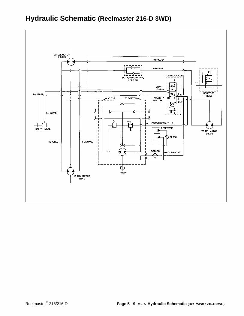
Hydraulic Schematic (Reelmaster 216-D 3WD)
Rev. AReelmaster® 216/216-D Page 5 - 9 Hydraulic Schematic (Reelmaster 216-D 3WD)
Special Tools
NOTE: Order special tools from the TORO SPECIALTOOLS AND APPLICATIONS GUIDE (COMMERCIALPRODUCTS). Some tools may be listed in theReelmaster 216 or Reelmaster 216-D Parts Catalog.Some tools may also be available from a local supplier.
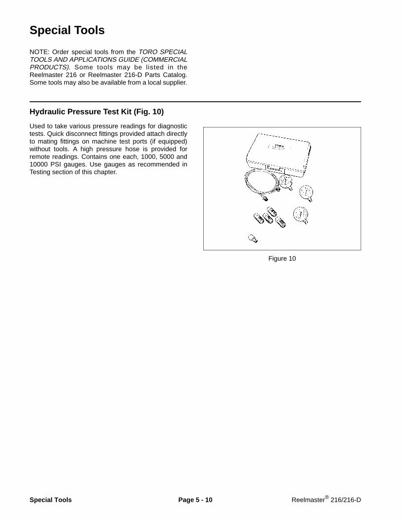
Hydraulic Pressure Test Kit (Fig. 10)
Used to take various pressure readings for diagnostictests. Quick disconnect fittings provided attach directlyto mating fittings on machine test ports (if equipped)without tools. A high pressure hose is provided forremote readings. Contains one each, 1000, 5000 and10000 PSI gauges. Use gauges as recommended inTesting section of this chapter.
Figure 10
Special Tools Page 5 - 10 Reelmaster® 216/216-D

Hydraulic Tester - With Pressure and Flow Capabilities (Fig. 11)
Figure 11
You must have o-ring face seal (ORFS) adapter fittingsfor this tester to use it on the Reelmaster 216/216-D.
1. INLET HOSE: Hose connected from the systemcircuit to the inlet side of the hydraulic tester.
2. LOAD VALVE: If required, upon turning the valve torestrict flow, a simulated working load is created in thecircuit.
3. LOW PRESSURE GAUGE: Low range gauge toprovide accurate reading at low pressure, 0 - 1000 PSI.
This gauge has a protector valve which cuts outwhen pressure is about to exceed the normal rangefor the gauge. The cutout pressure is adjustable.
4. HIGH PRESSURE GAUGE: High range gauge toaccommodate pressure beyond the capacity of the lowpressure gauge, 0 - 5000 PSI.
5. FLOW METER: This meter measures actual oil flowin the operation circuit, with a gauge rated at 15 GPM.
6. OUTLET HOSE: Hose from the outlet side of thehydraulic tester to be connected to the hydraulic systemcircuit.
Load Valve
OutletHose
Flow Meter
High PressureGauge
Inlet Hose
GaugeProtector Valve
Low PressureGauge
Reelmaster® 216/216-D Page 5 - 11 Special Tools

Hydraulic Oil Reservoir Plug (Fig. 13)
Used to temporarily plug the outlet of the hydraulic tankto retain most of the fluid when the hydraulic filter isremoved.
Figure 13
Rev. ASpecial Tools Page 5 - 12 Reelmaster® 216/216-D

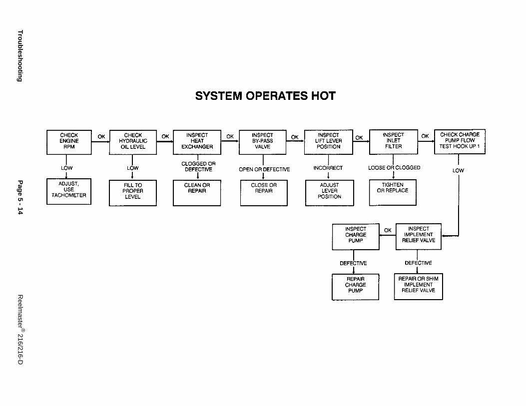
Troubleshooting
The cause of an improperly functioning hydraulic sys-tem is best diagnosed with the use of proper testingequipment and a thorough understanding of the com-plete hydraulic system.
A hydraulic system with an excessive increase in heator noise is a potential failure. Should either of theseconditions be noticed, immediately stop the machine,turn off the engine, locate the cause of the trouble, andcorrect it before allowing the machine to be used again.Continued use of an improperly functioning hydraulicsystem could lead to extensive internal componentdamage.
The charts that follow contain detailed information toassist in troubleshooting. There may possibly be morethan one cause for a machine malfunction. All causesshould be checked in the order in which they are listedon the charts.
Refer to the Testing section of this Chapter for precau-tions and specific test procedures.
Reelmaster® 216/216-D Page 5 - 13 Troubleshooting
Troubleshooting
Page 5 - 14
Reelm
aster ® 216/216-D

NOTE: Before checking for problems in hydrau-lic system, make sure brakes are released.Check for debris in brakes.
Reelm
aster ® 216/216-D
Page 5 - 15
Troubleshooting

Troubleshooting
Page 5 - 16
Reelm
aster ® 216/216-D

Testing
The most effective method for isolating problems in thehydraulic system is by using hydraulic test equipmentsuch as pressure gauges and flow meters in the circuitsduring various operational checks. (See the SpecialTools section in this Chapter.)
Failure to use gauges with the recommendedpressure (psi) rating as listed in the test pro-cedures could result in damage to the gaugeand possible personal injury from leakinghot oil.
Before Performing Hydraulic Tests
All obvious areas such as oil supply, filter, bindinglinkage, loose fasteners, or improper adjustments mustbe checked before assuming that a hydraulic compo-nent is the source of the problem being experienced.
Before disconnecting or performing any workon the hydraulic system, all pressure in thesystem must be relieved by stopping the en-gine and lowering the cutting units.
Keep body and hands away from pin holeleaks or nozzles that eject hydraulic fluid un-der high pressure. Use paper or cardboard,not hands, to search for leaks. Hydraulic fluidescaping under pressure can have sufficientforce to penetrate skin and do serious dam-age. If fluid is injected into the skin, it must besurgically removed within a few hours by adoctor familiar with this type of injury or gan-grene may result.
1. Thoroughly clean the machine before disconnectingor disassembling any hydraulic components. Alwayskeep in mind the need for cleanliness when working onhydraulic equipment.
2. Put caps or plugs on any hydraulic lines left open orexposed during testing or removal of components.
3. The engine must be in good operating condition. Usea tachometer to check engine RPM before doing hy-draulic tests. Engine speed can affect the accuracy ofthe tester readings.
4. To prevent damage to tester or components, the inletand the outlet hoses must be properly connected, andnot reversed (tester with pressure and flow capabilities).
5. To minimize the possibility of damaging components,completely open the load valve by turning it counter-clockwise (tester with pressure and flow capabilities).
6. Install fittings finger tight, far enough to insure thatthey are not cross-threaded, before tightening with awrench.
7. Position the tester hoses so that rotating machineparts will not make contact with them and result in hoseor tester damage.
8. Check the oil level in the reservoir.
9. Check the control linkage for improper adjustment,binding or broken parts.
10. All hydraulic tests should be made with the hydraulicoil at normal operating temperature.
CAUTION
WARNING
Reelmaster® 216/216-D Page 5 - 17 Testing

TEST HOOK-UP NO. 1: Charge Pump Flow and Implement Relief Pressure (Fig. 14, 15, 16)(Using Tester With Pressure and Flow Capabilities)
Tester Connection
Connect tester in series between implement pressureport of hydrostatic pump and pressure inlet port of liftvalve (Flow Control Open).
Reelmaster 216: Install tester between hose andfitting at front of valve.
Reelmaster 216-D: Install tester between hose andfitting at bottom front of pump.
TEST A: Charge Pump Flow andImplement Relief Pressure
1. Operate engine at full speed:
Reelmaster 216: 3600 ± 100 RPMReelmaster 216-D: 3200 ± 100 RPM
2. Make sure hydraulic oil is at operating temperature.
3. Traction pedal and lift valve in neutral. Parking brakeengaged.
4. While watching flow and pressure gauges, slowlyclose flow control valve until flow gauge reads 1 GPM.
TESTER READINGS: GPM Flow — Not less than 1GPM at Minimum 500 PSI.
Implement relief pressure should not exceed800 PSI.
Figure 14Reelmaster 216 valve connections
Figure 15Reelmaster 216-D pump connections
Figure 16(Reelmaster 216 2WD shown)
CAUTION
Testing Page 5 - 18 Reelmaster® 216/216-D
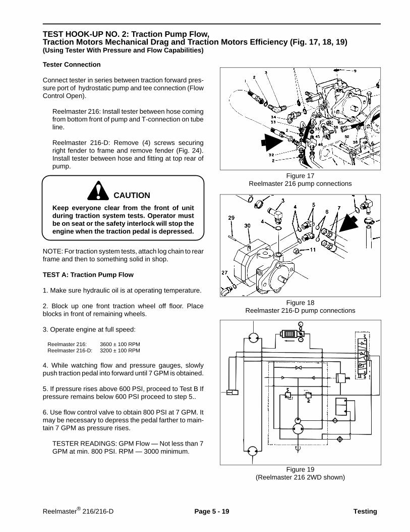
TEST HOOK-UP NO. 2: Traction Pump Flow,Traction Motors Mechanical Drag and Traction Motors Efficiency (Fig. 17, 18, 19)(Using Tester With Pressure and Flow Capabilities)
Tester Connection
Connect tester in series between traction forward pres-sure port of hydrostatic pump and tee connection (FlowControl Open).
Reelmaster 216: Install tester between hose comingfrom bottom front of pump and T-connection on tubeline.
Reelmaster 216-D: Remove (4) screws securingright fender to frame and remove fender (Fig. 24).Install tester between hose and fitting at top rear ofpump.
Keep everyone clear from the front of unitduring traction system tests. Operator mustbe on seat or the safety interlock will stop theengine when the traction pedal is depressed.
NOTE: For traction system tests, attach log chain to rearframe and then to something solid in shop.
TEST A: Traction Pump Flow
1. Make sure hydraulic oil is at operating temperature.
2. Block up one front traction wheel off floor. Placeblocks in front of remaining wheels.
3. Operate engine at full speed:
Reelmaster 216: 3600 ± 100 RPMReelmaster 216-D: 3200 ± 100 RPM
4. While watching flow and pressure gauges, slowlypush traction pedal into forward until 7 GPM is obtained.
5. If pressure rises above 600 PSI, proceed to Test B Ifpressure remains below 600 PSI proceed to step 5..
6. Use flow control valve to obtain 800 PSI at 7 GPM. Itmay be necessary to depress the pedal farther to main-tain 7 GPM as pressure rises.
TESTER READINGS: GPM Flow — Not less than 7GPM at min. 800 PSI. RPM — 3000 minimum.
Figure 17Reelmaster 216 pump connections
Figure 18Reelmaster 216-D pump connections
Figure 19(Reelmaster 216 2WD shown)
CAUTION
Reelmaster® 216/216-D Page 5 - 19 Testing

TEST B: Traction Motors Mechanical Drag
1. Make sure hydraulic oil is at operating temperature.
2. Block up one traction wheel off floor.
3. Place blocks in front of two remaining wheels.
4. Operate engine at full speed:
Reelmaster 216: 3600 ± 100 RPMReelmaster 216-D: 3200 ± 100 RPM
5. While watching flow and pressure gauges, slowypush traction pedal into forward, until 5 GPM is ob-tained.
TESTER READINGS: At 5 GPM, pressure not toexceed 400 PSI.
If pressure rises above 400 PSI, check:
A. For restriction in lines to or from rear motor.
B. For internal motor drag. If internal drag, removemotor and repair as necessary.
6. Repeat steps 1 - 5 for other wheel(s).
TEST C: Traction Motors Efficiency
1. Make sure hydraulic oil is at operating temperature.
2. All wheels on floor.
3. Block front of all wheels.
4. Operate engine at full speed:
Reelmaster 216: 3600 ± 100 RPMReelmaster 216-D: 3200 ± 100 RPM
5. While watching pressure gauges, slowly push tractionpedal into forward until 1000 PSI is obtained, read flowgauge.
TESTER READINGS: GPM Flow — Not more than2 GPM at 1000 PSI.
If flow reading is higher than 2 GPM, tester must beconnected in series between pressure line and individ-ual wheel motor to isolate defective motor. Repeat steps1 - 5 in above test for each motor.
Testing Page 5 - 20 Reelmaster® 216/216-D

Test Hook-up No. 3: Charge Pressure and Implement Relief Pressure (Fig. 20)
Gauge Connection
Connect a 1000 PSI hydraulic pressure gauge to chargepressure gauge port.
TEST A: Charge Pressure
1. Make sure hydraulic oil is at operating temperature.
2. Operate engine at full speed:
Reelmaster 216: 3600 ± 100 RPMReelmaster 216-D: 3200 ± 100 RPM
3. Traction pedal and lift valve in neutral. Parking brakeengaged.
TESTER READINGS: 70 – 150 PSI.
TEST B: Implement Relief Pressure
1. Make sure hydraulic oil is at operating temperature.
2. Operate engine at full speed:
Reelmaster 216: 3600 ± 100 RPMReelmaster 216-D: 3200 ± 100 RPM
3. Traction pedal in neutral and parking brake engaged.
4. Pull lift valve lever to raise cutting units and hold leverso systems goes over relief.
TESTER READINGS: 700 – 800 PSI.
Implement relief pressure should not exceed800 PSI.
NOTE: If pressure is within specification but the cuttingunits do not lift or lift slowly, check for mechanicalbinding, or internal leakage of lift cylinder.
Figure 20
1. 1000 PSI hydraulic pressure gauge
1
CAUTION
Reelmaster® 216/216-D Page 5 - 21 Testing

Test Hook-up No. 4: Traction Pressure (Fig. 21)
Gauge Connection
Connect a 10,000 PSI hydraulic pressure gauge toforward traction pressure gauge port.
TEST A: Traction Pressure
1. Make sure pump drive belt is properly adjusted andin good condition.
2. Make sure hydraulic oil is at operating temperature.
3. Operate engine at full speed:
Reelmaster 216: 3600 ± 100 RPMReelmaster 216-D: 3200 ± 100 RPM
4. Attach a heavy chain to rear frame of machine andthen to something solid in shop. Engage parking brake.
Keep everyone clear from the front of unitduring traction system tests. Operator mustbe on seat or the safety interlock will stop theengine when the traction pedal is depressed.
5. While watching pressure gauges, slowly push tractionpedal into forward until maximum pressure is obtained.
GAUGE READING: 4000 – 4500 PSI.
Figure 21
1. 10,000 PSI hydraulic pressure gauge
Rev. A
1
CAUTION
Testing Page 5 - 22 Reelmaster® 216/216-D

Test Hook-up No. 5: Traction Pressure (Reelmaster 216-D only) (Fig. 22)
Gauge Connection
Connect a 10,000 PSI hydraulic pressure gauge withextension hose to forward traction pressure quick dis-connect fitting on hydraulic tube line.
TEST A: Traction Pressure
1. Make sure pump drive belt is properly adjusted andin good condition.
2. Make sure hydraulic oil is at operating temperature.
3. Operate engine at full speed:
Reelmaster 216: 3600 ± 100 RPMReelmaster 216-D: 3200 ± 100 RPM
4. Attach a heavy chain to rear frame of machine andthen to something solid in shop. Engage parking brake.
Keep everyone clear from the front of unitduring traction system tests. Operator mustbe on seat or the safety interlock will stop theengine when the traction pedal is depressed.
5. While watching pressure gauges, slowly push tractionpedal into forward until maximum pressure is obtained.
GAUGE READING: 4000 – 4500 PSI.
Figure 22
1. Forward traction test port2. Reverse traction test port
Rev. A
1
2
CAUTION
Reelmaster® 216/216-D Page 5 - 23 Testing

Adjustments
Adjusting Transmission For Neutral (Reelmaster 216) (Fig. 23)
If the machine “creeps” when the traction control pedalis in the neutral position, the spring leaf assembly mustbe adjusted.
1. Block up under the frame so one of the front wheelsis off the floor. Place selector control in two wheel driveposition.
2. Start engine, move throttle to SLOW and check frontwheel that is off shop floor; it must not be rotating. Ifwheel is rotating forward, loosen capscrews and lightlytap bottom of pump plate counterclockwise (as viewedwhile facing pump plate). Lightly tap pump plate clock-wise if wheel is rotating backward. When wheel stopsrotating, tighten capscrews holding pump plate againstside of pump. Verify the adjustment with throttle inSLOW and FAST position.
3. Should the wheel continue to rotate,check for thefollowing:
A. Ball bearing is loose or worn out.
B. Plunger on interlock switch is sticking.
C. loose or missing fasteners.
D. Worn missing fasteners.
E. Pump lever loose on control shaft. (Correct byapplying Loctite 271 or 601 to shaft).
F. Weak or damaged leaf springs. Replace.
G. Internal pump component malfunction.
Figure 23
1. Pump plate2. Capscrews3. Leaf springs
Adjustments Page 5 - 24 Reelmaster® 216/216-D

Adjusting Transmission For Neutral (Reelmaster 216-D) (Fig. 24, 25)
If the machine “creeps” when the traction control pedalis in the neutral position, the spring leaf assembly mustbe adjusted.
1. Block up under the frame so one of the front wheelsis off the floor. Place selector control in two wheel driveposition.
2. To expose spring leaf assembly, remove (4) screwssecuring right fender to frame and remove fender.
3. Start engine, move throttle to SLOW and check frontwheel that is off shop floor; it must not be rotating. Ifwheel is rotating forward, loosen capscrews and lightlytap bottom of pump plate counterclockwise (as viewedwhile facing pump plate). Lightly tap pump plate clock-wise if wheel is rotating backward. When wheel stopsrotating, tighten capscrews holding pump plate againstside of pump. Verify the adjustment with throttle inSLOW and FAST position.
4. Should the wheel continue to rotate, check for thefollowing:
A. Ball bearing is loose or worn out.
B. Plunger on interlock switch is sticking.
C. Loose or missing fasteners.
D. Worn fasteners.
E. Pump lever loose on control shaft. (Correct byapplying Loctite 271 or 601 to shaft).
F. Weak or damaged leaf springs. Replace.
G. Internal pump component malfunction.
Figure 24
1. Right fender2. Fender mounting screws
Figure 25(View from bottom)
1. Pump plate2. Capscrews3. Leaf springs
2
1
Reelmaster® 216/216-D Page 5 - 25 Adjustments

Adjusting Tracton Pedal (Reelmaster 216) (Fig. 26, 27)
If traction pedal contacts footrest when pushed fullyforward or you cannot get maximum forward tractionspeed, an adjustment to the traction pedal linkage isrequired. There should be 3/8 inch clearance betweenpedal shaft and footrest when pedal is pushed fullyforward.
1. Remove (3) self-tapping screws securing supportscreen to hydraulic support panel. Remove screen.
2. Loosen jam nuts on each end of traction rod.
3. Rotate rod to get a dimension of 3/8 inch betweentraction pedal shaft and R.H. footrest when pedal ispushed fully forward.
4. Re-tighten jam nuts securing traction rod and reinstallsupport screen.
5. The stop for reverse travel (under pedal) may beadjusted for slower travel. Speeds in excess of 3 M.P.H.are not recommended.
Figure 26
1. Support screen
Figure 27
1. Traction rod
Adjustments Page 5 - 26 Reelmaster® 216/216-D

Adjusting Traction Pedal (Reelmaster 216-D) (Fig. 28, 29)
If traction pedal contacts footrest when pushed fullyforward or you cannot get maximum forward tractionspeed, an adjustment to the traction pedal linkage isrequired. There should be 1/16 inch between pedal stopcam and R.H. footrest when pedal is pushed fullyforward.
1. To expose traction rod, remove (4) screws securingright fender (Fig. 58) to frame and remove fender.
2. Loosen jam nuts on each end of traction rod.
3. Rotate rod until required to get a dimension of1/16 inch between pedal stop cam and R.H. footrestwhen pedal is pushed fully forward.
4. Re-tighten jam nuts securing traction rod adjustment.
5. The stop for reverse travel (under pedal) may beadjusted for slower travel. Speeds in excess of 3 MPHare not recommended.
Figure 28
1. Right fender2. Fender mounting screws
Figure 29
1. Traction rod
1
2
1
Reelmaster® 216/216-D Page 5 - 27 Adjustments

Pump Belt Adjustment (Fig. 30)
Make sure belts are properly tensioned to assure properoperation ot the machine and unnecessary wear. Checkbelt midway in span of belt. Check tension again on newbelts after 8 hours of operation.
Tighten nut on adjustment rod until desired belt tensionis attained. Belt should be tightened to 140 lbs. oftension.
NOTE: Tighten belt to eliminate slippage (squeelingunder load) but do not overtighten.
Figure 30
1. Nut2. Adjustment rod
Adjustments Page 5 - 28 Reelmaster® 216/216-D

Repairs
Removing Hydraulic System Components
1. Thoroughly clean the machine before disconnecting,removing or disassembling any hydraulic components.Always keep in mind the need for cleanliness whenworking on hydraulic equipment.
2. Put caps or plugs on any hydraulic lines or fittings leftopen or exposed.
3. Put labels on disconnected hydraulic lines and hosesfor proper installation after repairs are completed.
After Repair or Replacement of Components
1. Check oil level in hydraulic reservoir and add correctoil if necessary. Drain and refill hydraulic system reser-voir and change oil filter if component failure was severeor system is contaminated.
2. After repairs, check control linkage for proper adjust-ment, binding or broken parts.
3. If a pump was disconnected or removed, primesystem before operating. Disconnect fuel stop solenoidelectrical connector on diesel engine or disconnect ig-nition wires on gasoline engine. Turn ignition switch toengage starter for five (5) seconds to prime pump.Repeat cranking procedure again. Connect injectionpump fuel stop solenoid electrical connector on dieselengine or connect ignition wires on gasoline engine.Start engine and run at idle speed for a minimum of two(2) minutes.
4. After disconnecting or replacing any hydraulic com-ponents, operate machine functions slowly until air isout of system.
5. Check for hydraulic oil leaks. Shut off engine andcorrect leaks if necessary. Check oil level in hydraulicreservoir and add correct oil if necessary.
Reelmaster® 216/216-D Page 5 - 29 Repairs

Charge Pump (Fig. 31)
1. Note orientation of charge pump housing to adjacenthousing. Scribe a line or make punch marks to assureproper re-installation.
2. Clean the shaft extension to remove all sharp edges,burrs and abrasive residue to prevent shaft seal dam-age.
3. Remove hex head screws (Item 24) and slide thehousing assembly (Item 21, 22, & 23) over shaft holdingthe charge pump (gerotor) cartridge and remove drivepin (Item 26 ).
4. Remove the shaft seal (Item 23) and bearing(Item 22) from housing only if replacement is necessary.
5. Examine the wear surfaces of pump cartridge forexcessive scratching or heavy wear patterns. Replaceboth parts of this cartridge, if necessary. Do not replaceor interchange individual parts within the cartridge. Thedrive pin should always be replaced.
6. Visually inspect bearing (Item 22), O-ring (Item 27),and shaft seal (Item 23) and replace as required.
7. Coat both sides of pump cartridge (Item 25) andhousing face with hydraulic oil. Install drive pin (Item 26)into hole in shaft, then slide pump cartridge (Item 25)into place.
8. Wrap the shaft extension with plastic and then coatwith hydraulic oil to prevent damage to shaft seal.
9. Place O-ring into housing assembly (Item 21, 22, &23), then slide assembly into position over shaft. Lineup location marks, then insert torque screws (Item 24).
Figure 31
26
2725
21
2223
24
Repairs Page 5 - 30 Reelmaster® 216/216-D
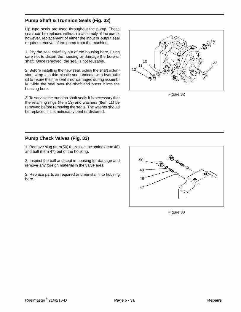
Pump Shaft & Trunnion Seals (Fig. 32)
Lip type seals are used throughout the pump. Theseseals can be replaced without disassembly of the pump;however, replacement of either the input or output sealrequires removal of the pump from the machine.
1. Pry the seal carefully out of the housing bore, usingcare not to distort the housing or damage the bore orshaft. Once removed, the seal is not reusable.
2. Before installing the new seal, polish the shaft exten-sion, wrap it in thin plastic and lubricate with hydraulicoil to insure that the seal is not damaged during assemb-ly. Slide the seal over the shaft and press it into thehousing bore.
3. To service the trunnion shaft seals it is necessary thatthe retaining rings (Item 13) and washers (Item 11) beremoved before removing the seals. The washer shouldbe replaced if it is noticeably bent or distorted.
Figure 32
Pump Check Valves (Fig. 33)
1. Remove plug (Item 50) then slide the spring (Item 48)and ball (Item 47) out of the housing.
2. Inspect the ball and seat in housing for damage andremove any foreign material in the valve area.
3. Replace parts as required and reinstall into housingbore.
Figure 33
47
48
49
50
2310
1311
Reelmaster® 216/216-D Page 5 - 31 Repairs

Pump Relief Valves (Fig. 34)
1. Remove plug ,then slide the spring and poppet out ofthe housing.
IMPORTANT: Do not interchange parts betweencharge and implement relief valves. Do not altershims unless adjusting pressure setting of valve.
2. Inspect the poppet and seat in housing for damageand remove any foreign material in the valve area.
3. Replace parts as required and reinstall into housingbore.
Figure 34
Implement relief
Charge relief
14
1551
1718
Repairs Page 5 - 32 Reelmaster® 216/216-D

Pump Disassembly (Fig. 35, 36, 37, 38)
The following procedures are for major repair of thevariable displacement pump. These instructions beginwith the removal of the end cap. Remove the chargepump, seals, check valves and relief valves beforedoing major disassembly (See procedures on previouspages of this section).
Figure 35
Figure 36
1. When cap screws (Item 46) are loosened, internalspring loading will cause end cap (Item 45) to separateslightly. Loosen screws evenly to prevent distortion ofparts. If separation does not occur as screws are loos-ened, tap end cap with soft hammer until parts separate.
IMPORTANT: Most parts have critical, high toler-ance surfaces. Use caution to prevent damage tothese surfaces during assembly. Protect exposedsurfaces, opens and ports from damage and foreignmaterial.
2. Remove end cap (Item 45), however, make sure valveplate (Item 40) does not fall and become damaged. Ifvalve plate tends to lift off with end cap, hold it in placeon end cap and remove both parts together. If valveplate remains on cylinder block, remove it at this time.
3. The end cap is an assembly consisting of a needlebearing which is a press fit in the end cap and the valveplate locating pin (Item 41). Inspect bearing (Item 42)and remove if replacement is required.
44
41
8
40
42
43
46
45
Reelmaster® 216/216-D Page 5 - 33 Repairs

Figure 37
4. Lift out the cylinder block assembly (Item 5). Thepistons may come out of the cylinder block. There is nospecial orientation of piston to bore that needs to bemaintained. Do not attempt to disassemble the springand other parts from the center bore of the cylinderblock. The entire cylinder block assembly (Item 5)should be replaced if any of its components are dam-aged.
5. Visually inspect wear surfaces of valve plate, cylinderblock and slippers for damage. Check to be sure pistonsare free in bores.
6. Remove thrust plate (Item 39) from counterbore inface of swashplate (Item 37). Visually inspect both sidesfor damage and flatness.
8
39
5
Repairs Page 5 - 34 Reelmaster® 216/216-D

Figure 38
7. Place the pump housing (Item 8) with the large cavityup. Use care not to scratch the port face surface.
8. Using a 3/16 in. diameter drift punch, drive spring pin(Item 38) out of trunnion and control shafts(Item 12 & 28). The pump housing is provided with acast recess so that the pins can be driven free oftrunnion and control shafts.
9. Drive each trunnion shaft out of swashplate boretoward outside of housing. Once clear of swashplate
bore, the shaft can be removed easily. The swashplate(Item 37) is then removed from the pump housing.
10. Inspect the needle bearings (Item 9). If replacementis required press out the old bearings.
11. Remove retaining ring (Item 36) from housing, thenpress out shaft and bearing assembly (Item 6, 34 & 35).The bearing (Item 35) can be removed from shaft, ifnecessary, after removing retaining ring (Item 34).
37
634
36
38
12
8
35
28
9
Reelmaster® 216/216-D Page 5 - 35 Repairs

Assembly of Pump (Fig. 39, 40, 41, 42)
Figure 39
1. Before assembling, wash parts in solvent. Dry partswith compressed air. Do not wipe them dry with a clothor paper as lint and dirt may remain. Apply a light coatingof hydraulic oil to parts before assembling.
IMPORTANT: Most parts have critical, high toler-ance surfaces. Use caution to prevent damage tothese surfaces during assembly. Protect exposedsurfaces, opens and ports from damage and foreignmaterial.
2. Assemble shaft (Item 6), bearing (Item 35) and retain-ing ring (Item 34) then press into housing (Item 8). Installretaining ring (Item 36) in groove in housing.
3. Place housing (Item 8) with large cavity up. Use carenot to scratch the port face surface.
4. Press needle bearings (Item 9) into each side ofhousing until flush to 1/64 inch below counterbore for lipseals.
5. Place swashplate (Item 37) into housing with coun-terbore for thrust plate up. Install control shaft (Item 28)and trunnion shaft (Item 12) being certain control shaftis on proper side. Align holes in swashplate and shafts.
37
634
36
38
12
8
35
28
9
Repairs Page 5 - 36 Reelmaster® 216/216-D

Figure 40
6. Install new pins through swashplate and shaft. Usetwo (2) pins in control shaft (Item 28), installing first pinuntil second pin can be started, then driving in both pinstogether until the last pin is 1/4 inch below swashplate.
7. Install one (1) pin in trunnion shaft (Item 12), drivingit in until it is 1/4 inch below swashplate.
8. The swashplate should swing freely in the pumphousing to 150° each side of center.
Reelmaster® 216/216-D Page 5 - 37 Repairs

Figure 41
9. Lubricate thrust plate (Item 39) with clean hydraulicoil and insert in counterbore of swashplate.
10. Assemble cylinder block parts if necessary andlubricate with clean hydraulic oil. There is no specialorientation of piston to bore that needs to be maintained.
11. Place the housing assembly in a horizontal position.
12. Slide cylinder block assembly (Item 5) over shaft andengage spline. Be certain that pistons and thrust plateremain in place. When properly installed a slight springtension can be felt when pushing on cylinder block.
13. Lubricate exposed face of cylinder block with cleanhydraulic oil.
8
39
5
Repairs Page 5 - 38 Reelmaster® 216/216-D

Figure 42
14. Properly orient the end cap (Item 45) and housing(Item 8). Align the O-rings (Item 44) with the matingholes in the housing.
15. Press bearing (Item 42) into end cap leaving 3/32 to1/8 inch protruding beyond face. The valve plate(Item 40) pilots on this bearing.
16. Insert locating pin (Item 41) into end cap. Lubricatethe slotted side of the pump valve plate (Item 40) andslip it over the pin and protruding bearing.
17. Place the gasket (Item 42) on housing (Item 8) theninstall end cap and valve plate. Hold the valve plate soit does not drop off during assembly.
18. Install four (4) screws (Item 46) and tighten alter-nately until the end cap and housing are pulled com-pletely together. Torque to 27-37 ft. lbs. Check for properinternal assembly by slowly rotating pump and controlshafts while tightening these screws.
19. The remaining components (charge pump, chargerelief valve, seals, etc.) can now be assembled de-scribed on previous pages.
44
41
8
40
42
43
46
45
Reelmaster® 216/216-D Page 5 - 39 Repairs

Wheel Motor (Fig. 43)
Figure 43
1. Screw 9. Body & bearing assembly 16. Retainer pin2. Cover & bearing ass’y 10. Shaft 17. Lip seal3. Plug 11. Key 19. Thrust washer4. Seal 12. O-ring 20. Thrust bearing5. IGR assembly 13. Nut 21. Snap ring6. Check ball 14. Snap ring7. Valve plate 15. Dust seal
Disassembly of Shaft and Front Seal Assembly
1. Put the motor on a clean, flat surface with the shaftfacing up. Clean the front end of the motor to avoidcontaminating the internal parts during the procedure.
2. Remove key (Item 11) from the shaft.
3. Remove the snap ring (Item 14) using a snap ringpliers.
4. Pull the shaft (Item 10) out vertically.
IMPORTANT: When pulling shaft vertically, do notrotate the shaft or move the motor as this may alterinternal timing.
5. With the seal retainer assembly and shaft assemblyremoved, remove all the parts from the shaft and inspectthe various parts of the seal assembly (Item 15, 16, 17),shaft (Item 10) and thrust bearing assembly (Item 19,20, 21). Replace any worn or damaged parts. Alwaysreplace the seal retainer assembly (Item 15, 16, 17). The
shaft should have smooth polished surfaces in thebearing and seal areas. If the shaft is lightly scratchedin these areas, polish with fine emery paper in a circum-ferential direction. However, if the shaft has any pittingor deep scratches, the entire motor should be disassem-bled for inspection.
Assembly of Shaft and Front Seal Assembly
1. Assemble the thrust washers (Item 19) and thrustbearing (Item 20) on the shaft using the snap ring (Item21). The snap ring sharp edges MUST face away fromthe thrust washers with the thrust bearing (Item 20)between the washers.
2. Slowly lower the spline end of the shaft (Item 10)assembly into the motor body using caution not to rotatethe internal parts once the shaft spline starts to engage.
3. Put the lightly oiled o-ring (Item 12) into the groove inthe body bore.
Repairs Page 5 - 40 Reelmaster® 216/216-D

4. Gently slide the oiled seal retainer assembly (Item 15,16, 17) over the shaft, chamfered side first, and pressinto the body bore. When fully in place, the body snapring groove will be visible.
5. Install the snap ring (Item 14) into its body groove withthe snap ring’s sharp edges facing outward and theretainer pin between the snap ring lugs, Be sure thesnap ring is completely seated in the groove.
Disassembly of Cover Section of Motor
IMPORTANT: Before DISASSEMBLING the motor,plug open ports and clean all dirt from the outsideof the motor.
1. Remove the key (Item 11) from the shaft.
2. Mount the motor in a vice or other holding device withthe shaft facing down.
3. Remove the eight bolts (Item 1).
4. Remove the cover/bearing assembly (Item 2) and thesquare ring seal (Item 4).
5. Remove the IGR set components (Item 5) startingwith the outer locating ring, rollers, outer rolls, inner rotorand valve plate (Item 7). If any of these components aredamaged, the entire IGR assembly must be replaced.
6. Remove the two check balls (Item 6).
NOTE: The check balls may fall into the body taperedholes or into the body valve ports during disassembly.Be sure that the check balls are removed.
Disassembly of Shaft Section of Motor
(See Disassembly of Shaft and Front Seal Assemblyunder Main Shaft Seal and/or Shaft Replacement.)
Assembly of Complete Motor
IMPORTANT: Before ASSEMBLING the motor,lightly oil all seals, rollers and threaded bolt ends.
1. Before assembly, all parts must be clean free of nicksand burrs. Wash parts in solvent. Dry parts with com-pressed air. Do not wipe them dry with a cloth or paperas lint and dirt may remain.
2. Mount the body with the pilot and bearing facing upin a vise or other holding mechanism.
3. Insert the shaft (Figure 37, Item 10) and install sealsand thrust bearings. (See Assembly of Shaft and FrontSeal Assembly under Main Shaft Seal and/or ShaftReplacement.)
4. Mount the body with the pilot and bearing facing downin a vise or other holding fixture.
5. Put the rotary valve (Item 7) on the shaft spline with“T” shaped slots on first.
6. Next put the IGR inner member on the shaft splinewith the semi-circular roll pockets between the rotaryvalve ports. NOTE: This step “times” the motor forrotation.
7. Put the contour member of the IGR over the inner andinsert seven rolls into the inner pockets (large diameterrolls).
8. Lightly oil the square ring seal (Item 4) and put in thebody groove.
9. Put the check balls (Item 6) over the two 1/8" inchdiameter holes in the body. Be sure the check balls donot fall into the body tapped holes.
10. Put the locating ring section (4.5 inch diameter) ofthe IGR (Item 5) onto the body with the check ball holesfacing downward over the balls. Align the eight boltholes in the locating ring with the eight holes in the body.The holes align in only one position.
NOTE: Be sure not to dislodge the body square ring sealwhile moving the locating ring.
11. Install the eight locating ring rollers (small diameterrolls) into their pockets and oil lightly.
12. Put the other lightly oiled square ring seal (Item 4)into the groove in the cover and put the cover over theshaft end and align the bolt holes.
13. Install the eight bolts with the lightly oiled threadends into the bolt holes and tighten diagonally to 30 ft-lb.The motor is now ready for installation.
NOTE: The shaft may not turn freely after assembly. Ashort running period may be required.
When installing the wheel hub onto the motor shaft,tighten the castle nut (Item 13) to 80-90 ft-lb, thencontinue tightening until the cotter pin slot lines up thehole in the shaft.
Rev. AReelmaster® 216/216-D Page 5 - 41 Repairs

Lift Control Valve (Fig. 44)
1. After removing control valve from machine, washvalve in solvent and dry it thoroughly.
2. Carefully mount control valve into a vise so thatcontrol valve mounting pads are against jaws of vise.The control valve spool snap ring (Item 14) should befacing up.
3. Remove plug (Item 1) from side of valve body. Insidethe valve body, under the plug, there is a spring (Item 3),ball (Item 4), and cam pin (Item 6); remove these parts.
4. Repeat step 3 for the other plug.
5. Remove snap ring (Item 14) located in bottom of valvebody. This snap ring retains spool centering springassembly. Remove spool snap ring (Item 13), springretainer (Item 10), spacer (Item 12), and spring(Item 11).
6. Carefully push and twist control valve spool to removeit from valve body. Set spool assembly aside.
7. Use a hooked scribe or thin screwdriver to removeO-rings (Item 9) from inside bore of valve body (becareful not to scratch valve bore finish).
8. Inspect all components of control valve assembly forwear, paying special attention to valve spool. Signs ofwear on one side of spool may indicate a bent spool.Inspect spool for flatness, and replace it if necessary.
9. Wash parts in solvent. Dry parts with compressed air.Do not wipe them dry with a cloth or paper as lint anddirt may remain.
10. Prior to reassembly, coat all O-rings with oil. Installspool into valve body before inserting cam pin (Item 6),ball (Item 4), spring (Item 3), and hex plug (Item 1).
11. Complete reassembly by reversing these proce-dures and installing new O-rings and seals.
Figure 44
Repairs Page 5 - 42 Reelmaster® 216/216-D

Lift Cylinder (Fig. 45, 46, 47)
Figure 45
1. After removing cylinder, pump oil out of cylinder intoa drain pan by SLOWLY moving cylinder’s piston in andout of cylinder bore.
2. Plug ports and clean the outside of cylinder.
IMPORTANT: To prevent damage when clampingcylinder barrel in a vise, clamp only on pivot end.
3. Mount cylinder in a vise so shaft end of cylinder istilted up slightly. Do not close vise so firmly that thebarrel could become distorted.
4. Use a spanner wrench to rotate head (Item 3) andremove retaining ring (Item 12). Figure 46
Removing retaining ring
Retaining ring
Spanner wrench
12
3
4
5
6
7
8
9
10
11
12
13
Reelmaster® 216/216-D Page 5 - 43 Repairs

5. Grasp end of shaft (Item 4) and use a twisting andpulling motion to carefully extract piston (Item 8), shaft(Item 4), and head (Item 3) from barrel (Item 6).
IMPORTANT: Do not clamp vise jaws against shaftsurface. Protect shaft surface before mounting invise.
6. Securely mount shaft (Item 4) in a vise, clamping viseon flats of shaft. Remove lock nut (Item 5) from thepiston end of shaft. Remove the piston. Slide head(Item 3) off of shaft.
7. Remove and discard all seals and back-up rings(Items 1–2, 7, 9–11, 13).
8. Wash parts in solvent. Dry parts with compressed air.Do not wipe them dry with a cloth or paper as lint anddirt may remain.
9. Inspect internal surface of barrel (Item 6) for damage(deep scratches, out-of-round, etc.). Inspect head(Item 3), shaft (Item 4) and piston (Item 8) for evidenceof excessive scoring, pitting, or wear. Replace anydefective parts.
10. Use new seals (Items 1–2, 7, 9–11, 13) whenreassembling. Put a light coating of hydraulic oil on allnew seals and back-up washers. Install the new sealsand back-up washers. Install head (Item 3) onto shaft(Item 4). Install piston (Item 8) onto shaft and tightenlock nut (Item 5).
11. Put a light coating of hydraulic oil on all cylinder partsto ease assembly. Slide shaft assembly and head intobarrel being careful not to damage seals.
12. Install retaining ring (Item 12) to secure assembly inbarrel. Align key slot in head with access groove inbarrel. Rotate heat clockwise as far as the retaining ringwill allow. The offset end of the retaining ring will beagainst the left side of the barrel groove as shown(Fig. 47).
Figure 47
Installing retaining ring
Rev. A
Retaining ring(Offset end against leftside of barrel grooveafter installing)
Spanner wrench
Repairs Page 5 - 44 Reelmaster® 216/216-D

3WD Selector Valve (Fig. 48)
Figure 48
1. After removing selector valve from machine, washvalve in solvent and dry it thoroughly.
2. Carefully mount valve assembly into a vise so thatcontrol valve mounting pads are against jaws of vise.
3. Remove retaining ring (Item 3) from end of spool.
4. Use knob (Item 9) to carefully pull and twist valvespool out of the valve body.
5. Remove roll pin (Item 5). Be careful not to scratch ordamage spool.
6. Remove plug (Item 1) from end of spool (be carefullnot ot drop ball (Item 4) which can fall out after plug isremoved. Hold the spool with one hand and allow checkball fall into your other hand..
7. Use a hooked scribe or thin screwdriver to removeback-up washers (Item 6) and O-rings (Item 7) frominside bore of valve body (be careful not to scratch valvebore finish).
8. Inspect all components of control valve assembly forwear, paying special attention to valve spool. Signs ofwear on one side of spool may indicate a bent spool.Inspect spool for flatness, and replace it if necessary.
9. Wash parts in solvent. Dry parts with compressed air.Do not wipe them dry with a cloth or paper as lint anddirt may remain.
10. Use new seals (Items 2, 6, 7). Before assembling,coat all O-rings and back-up rings with hydraulic oil.Install new seals (Items 2, 6, 7).
11. Install check ball (Item 4) and roll pin (Item 5). Installplug (Item 1) with new O-ring (Item 2).
12. Coat spool with hydraulic oil and install into valvebody, being careful not to damage the seals.
13. Install snap ring (Item 3).
Rev. AReelmaster® 216/216-D Page 5 - 45 Repairs

Repairs Page 5 - 46 Reelmaster® 216/216-D

Chapter 6
Electrical System
Table of Contents
WIRING SCHEMATICS . . . . . . . . . . . . . . . . . . . . . . 2Reelmaster 216 (S/N 99999 & Below) . . . . . . . . . . . . 2Reelmaster 216 (S/N 10001 – 19999) . . . . . . . . . . . . 3Reelmaster 216 (S/N 20001 & Up) . . . . . . . . . . . . . . 4Reelmaster 216-D . . . . . . . . . . . . . . . . . . . . . . . . 5
SPECIAL TOOLS . . . . . . . . . . . . . . . . . . . . . . . . . . . 6TROUBLESHOOTING (Reelmaster 216) . . . . . . . . . . . 8
Starting Problems . . . . . . . . . . . . . . . . . . . . . . . . 8General Run and Transport Problems. . . . . . . . . 11Cutting Operation Problems . . . . . . . . . . . . . . . 12Verify Interlock Operation . . . . . . . . . . . . . . . . . 13
TROUBLESHOOTING (Reelmaster 216-D) . . . . . . . . . 14Starting Problems . . . . . . . . . . . . . . . . . . . . . . . 14General Run and Transport Problems. . . . . . . . 17Cutting Operation Problems . . . . . . . . . . . . . . . 18Verify Interlock Operation . . . . . . . . . . . . . . . . . 19
TESTING . . . . . . . . . . . . . . . . . . . . . . . . . . . . . . . . 20Ignition Key Switch . . . . . . . . . . . . . . . . . . . . . . 20Seat Switch . . . . . . . . . . . . . . . . . . . . . . . . . . . . 21Traction (Neutral) Switch. . . . . . . . . . . . . . . . . . 22Cutting Unit Interlock Switch . . . . . . . . . . . . . . . 22Cutting Unit Clutch (Reel Drive) Switch . . . . . . 23
Start and High Temp. Relays (Reelmaster 216-D only) . . . . . . . . . . . . . . . . . . . . 24Glow Plugs (Reelmaster 216-D only) . . . . . . . . . . . . 25Battery . . . . . . . . . . . . . . . . . . . . . . . . . . . . . . . . 25Injection Pump (ETR) Solenoid (Reelmaster 216-D only) . . . . . . . . . . . . . . . . . . . . 26Indicator Lights and Gauges . . . . . . . . . . . . . . . 27High Temperature Shut-Down Switch (Reelmaster 216-D only) . . . . . . . . . . . . . . . . . . . . 28Temperature Gauge Sender (Reelmaster 216-D only) . . . . . . . . . . . . . . . . . . . . 28Engine Oil Pressure Switch (Reelmaster 216-D only) . . . . . . . . . . . . . . . . . . . . 29Starter Solenoid (Reelmaster 216 only). . . . . . . . . . . . . . . . . . . . . . 30Cutting Unit Clutch. . . . . . . . . . . . . . . . . . . . . . . 30Interlock Module (Reelmaster 216 only). . . . . . . . . . . . . . . . . . . . . . 30
REPAIRS . . . . . . . . . . . . . . . . . . . . . . . . . . . . . . . . 31Battery Service . . . . . . . . . . . . . . . . . . . . . . . . . 31Fuses. . . . . . . . . . . . . . . . . . . . . . . . . . . . . . . . . 32Traction (Neutral) Switch Replacement. . . . . . . 33Cutting Unit Interlock Switch Replacement . . . . 34
Reelmaster® 216/216-D Page 6 - 1 Table of Contents
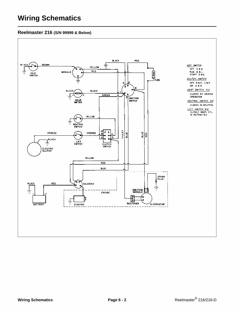
Wiring Schematics
Reelmaster 216 (S/N 99999 & Below)
Wiring Schematics Page 6 - 2 Reelmaster® 216/216-D

Reelmaster 216 (S/N 10001 – 19999)
Reelmaster® 216/216-D Page 6 - 3 Wiring Schematics

Reelmaster 216 (S/N 20001 & Up)
Wiring Schematics Page 6 - 4 Reelmaster® 216/216-D
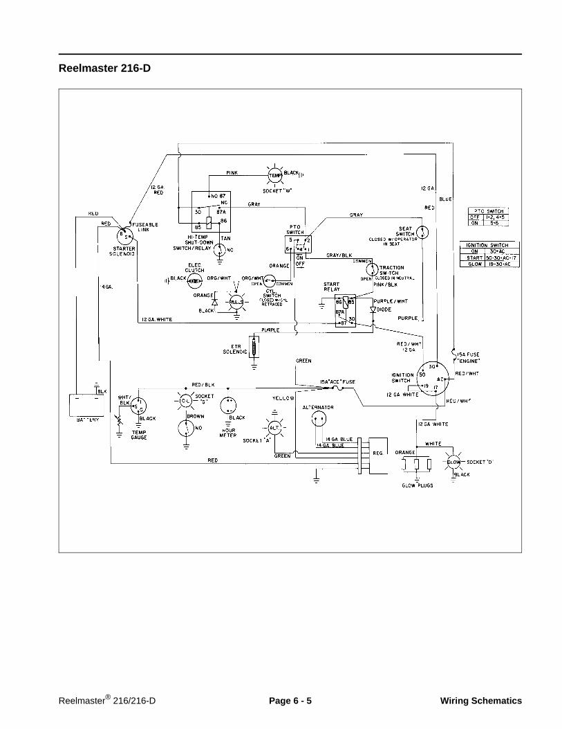
Reelmaster 216-D
Reelmaster® 216/216-D Page 6 - 5 Wiring Schematics

Special Tools
NOTE: Order special tools from the TORO SPECIALTOOLS AND APPLICATIONS GUIDE (COMMERCIALPRODUCTS). Some tools may be available from a localsupplier.
Continuity Tester
Battery powered test lamp which is helpful in testing forcontinuity of circuits and electrical components whenthe current is off.
Figure 1
Volt - Ohm - Amp Meter
The meter can test electrical components and circuitsfor current, resistance, or voltage draw.
Figure 2
Special Tools Page 6 - 6 Reelmaster® 216/216-D

Skin-Over Grease
Special non-conductive grease which forms a light pro-tective skin to help waterproof electrical switches andcontacts.
Figure 3
Reelmaster® 216/216-D Page 6 - 7 Special Tools

Troubleshooting (Reelmaster 216)
Remove all jewelry, especially rings andwatches, before doing any electrical trou-bleshooting or testing. Disconnect the bat-tery cables unless the test requires batteryvoltage.
For effective troubleshooting and repairs, you MUSThave a good understanding of the electrical circuits andcomponents used on this machine. (See ElectricalSchematics and Diagrams section of this chapter.)
Study the operating characteristics preceding the elec-trical failure to help identify the area of difficulty. Try toisolate the failure to a specific functional system; thencheck that area, repairing one component at a time.Attempting to repair more than one system at one timewill lead to confusion.
Possible Causes and Corrections in the troubleshootingcharts should be checked in the order in which they arelisted.
If the machine being repaired has any interlock switchesby-passed, they must be reconnected for proper trou-bleshooting and safety.
Engine Starting Problems
Condition Possible Cause Correction
________________________________________________________________________________________________________________________________________________________
Starter solenoid clicks, but en-gine will not crank. (If solenoidclicks, problem is not in interlocksystem.)
Low battery charge
Loose or corroded battery cables.Loose or corroded ground.
Faulty wiring at starter.
Loose starter mounting bolts.
Faulty starter.
Faulty starter solenoid.
Engine seized.
Charge battery. Replace battery ifit will not hold a charge.
Clean and tighten, or repair asnecessary.
Repair wiring.
Clean mounting surface andtighten bolts.
Repair or replace starter.
Replace starter solenoid.
Repair engine.
CAUTION
Troubleshooting (Reelmaster 216) Page 6 - 8 Reelmaster® 216/216-D

Starting Problems (continued)
Condition Possible Cause Correction
________________________________________________________________________________________________________________________________________________________
Nothing happens when start at-tempt is made.
Battery is dead.
Loose or corroded battery cables.Loose or corroded ground.
Fuse open.
Traction neutral switch out of ad-justment or faulty.
Traction neutral switch wiringloose, corroded or damaged.
Cutting unit clutch switch engagedor faulty.
Cutting unit clutch switch wiringloose, corroded or damaged.
Ignition switch faulty.
Ignition switch wiring loose, cor-roded or damaged.
Starter solenoid faulty.
Starter solenoid wires loose, cor-roded or damaged.
Charge battery. Replace battery ifit will not hold a charge.
Clean and tighten or repair asnecessary.
Check fuse and replace if fuse isopen. If fuse burns out often, findand correct cause.
Test switch and replace if faulty.Make sure wires are connectedto “COMMON” and “NORMALLYOPEN” (N.O.) terminals.
Repair wiring.
Make sure switch is OFF. Testswitch and replace if faulty.
Repair wiring.
Test ignition switch. Replace iffaulty.
Repair wiring.
Test starter solenoid. Replace iffaulty.
Clean and tighten or repair asnecessary.
Reelmaster® 216/216-D Page 6 - 9 Troubleshooting (Reelmaster 216)

Starting Problems (continued)
Condition Possible Cause Correction
________________________________________________________________________________________________________________________________________________________
Engine cranks, but does not start. Engine wiring connector or wiresloose, corroded or damaged.
Engine, engine ignition, or fuel sys-tem problem.
Interlock module faulty.
Repair wiring.
See Troubleshooting section ofKohler Magnum Engine ServiceManual.
Replace interlock module.
________________________________________________________________________________________________________________________________________________________
Engine cranks (but should not)with traction pedal out of neutral.
Traction neutral switch out of ad-justment or faulty.
Test switch and replace if faulty.Make sure wires are connectedto “COMMON” and “NORMALLYOPEN” (N.O.) terminals.
________________________________________________________________________________________________________________________________________________________
Engine cranks (but should not)with cutting unit clutch switch ON.
Cutting unit clutch switch faulty. Replace switch.
Troubleshooting (Reelmaster 216) Page 6 - 10 Reelmaster® 216/216-D

General Run and Transport Problems
Condition Possible Cause Correction
________________________________________________________________________________________________________________________________________________________
Engine continues to run (butshould not) when traction pedal isdepressed with no operator onseat.
Seat switch plunger depressedwith no operator on seat.
Seat switch faulty or out of adjust-ment.
Traction neutral switch faulty or outof adjustment.
Interlock module faulty.
Check for seat support springthat is broken, missing or stuck indown position.
Check for binding seat pivothinge.
Check for waterlogged seat.
Test seat switch. Adjust or re-place if faulty.
Test switch, Adjust or replace iffautly. Check for correct terminalconnections.
Replace interlock module.
________________________________________________________________________________________________________________________________________________________
Engine kills when traction pedalis depressed or cutting unit clutchswitch is turned ON.
Operator sitting too far forward onseat (seat switch not depressed).
Seat hinge, support pin or springbinding, preventing seat switchfrom closing.
Seat switch is faulty or out of ad-justment.
Seat switch wiring loose, corrodedor damaged.
Interlock module wiring loose, cor-roded or damaged.
Interlock module faulty.
Instruct operator.
Repair seat pivot and support.
Test seat switch. Adjust or re-place if faulty.
Repair wiring.
Repair wiring.
Replace interlock module.
________________________________________________________________________________________________________________________________________________________
Battery does not charge. Loose, corroded or broken wire(s).
Faulty alternator.
Dead battery.
Repair wiring.
Test alternator and replace iffaulty.
Charge battery. Replace battery ifit will not hold a charge.
________________________________________________________________________________________________________________________________________________________
Battery continuously charges athigh rate.
Regulator / rectifier faulty. Replace regulator / rectifier.
Reelmaster® 216/216-D Page 6 - 11 Troubleshooting (Reelmaster 216)

Cutting Unit Operation Problems
Condition Possible Cause Correction
________________________________________________________________________________________________________________________________________________________
Engine continues to run (butshould not) when cutting unitclutch switch is ON with no opera-tor on the seat.
Seat switch plunger depressedwith no operator on seat.
Seat switch faulty or out of adjust-ment.
Interlock module faulty.
Check for seat support springthat is broken, missing or stuck indown position.
Check for binding seat pivothinge.
Check for waterlogged seat.
Test seat switch. Adjust or re-place if faulty.
Interlock module faulty.
________________________________________________________________________________________________________________________________________________________
Cutting units run (but should not)when raised, but shut off with cut-ting unit engage switch.
Cutting unit interlock switch faulty. Test switch and replace if faulty.Make sure wires are connectedto “COMMON” and “NORMALLYOPEN” (N.O.) terminals.
________________________________________________________________________________________________________________________________________________________
Cutting units shut off whenraised, but do not shut off withcutting unit engage switch.
Cutting unit engage switch faulty. Test switch. Replace if faulty.
________________________________________________________________________________________________________________________________________________________
Cutting units do not engage. Fuse open. (NOTE: Hourmeter willalso fail to operate.)
Cutting unit clutch switch faulty.
Cutting unit clutch switch wiringloose, corroded or damaged.
Cutting unit interlock switch faulty.
Cutting unit interlock switch wiringfaulty.
Clutch faulty or out of adjustment.
Clutch wiring faulty.
Check fuse and replace if fuse isopen. If fuse burns out often, findand correct cause.
Test switch. Replace if faulty..
Repair wiring.
Test switch. Replace if faulty.Make sure wires are connectedto “COMMON” and “NORMALLYOPEN” (N.O.) terminals.
Repair wiring.
Test clutch. Make sure clutch airgap is properly adjusted..
Repair wiring.
Troubleshooting (Reelmaster 216) Page 6 - 12 Reelmaster® 216/216-D

Verify Interlock System Operation
The purpose of the interlock system is to prevent theengine from cranking or starting unless the tractionpedal is in NEUTRAL and the cutting unit engagementswitch is DISENGAGED. In addition, the engine will stopwhen the cutting unit engagement switch is engaged ortraction pedal is depressed with the operator off theseat.
The interlock switches are for the operator’sprotection, so do not disconnect them. Checkoperation of the switches daily to assure in-terlock system is operating. If a switch isdefective, replace it before operating. Regard-less if switches are operating properly or not,replace them every two years to assure maxi-mum safety. do not rely entirely on safetyswitches - use common sense!
To check interlock system operation:
1. Move machine to a wide open area free of debris andbystanders. Raise cutting units and stop engine. En-gage parking brake.
2. Sit on seat. Move Reel Drive switch to ENGAGEposition. Try to start engine. If engine cranks, there maybe a malfunction in interlock system. Repair immedi-ately. If engine does not crank, proceed to step 3.
3. Sit on seat. Depress traction pedal in forward andreverse directions while trying to start engine. If enginecranks while pedal is in forward or reverse position,there may be a malfunction in interlock system. Repairimmediately. If engine does not crank, proceed tostep 4.
4. With cutting units in raised position, sit on seat andstart engine. Move Reel Drive switch to ENGAGE posi-tion. Lower cutting units to ground. Cutting unit reelsshould start turning when cutting units are lowered.Raise cutting units and verify that they stop. If they donot stop, there may be a malfunction in interlock system.Repair immediately. If cutting units stop, proceed tostep 5.
5. While sitting on seat with cutting units in raisedposition and engine running, move Reel Drive switch toENGAGE position. Hold on to steering wheel and raiseup off of seat. Engine should stop. If engine does notstop, there is a malfunction in interlock system. Repairimmediately. If engine stops, seat switch is operatingcorrectly.
CAUTION
Reelmaster® 216/216-D Page 6 - 13 Troubleshooting (Reelmaster 216)

Troubleshooting (Reelmaster 216-D)
Remove all jewelry, especially rings andwatches, before doing any electrical trou-bleshooting or testing. Disconnect the bat-tery cables unless the test requires batteryvoltage.
For effective troubleshooting and repairs, you MUSThave a good understanding of the electrical circuits andcomponents used on this machine. (See ElectricalSchematics and Diagrams section of this chapter.)
Study the operating characteristics preceding the elec-trical failure to help identify the area of difficulty. Try toisolate the failure to a specific functional system; thencheck that area, repairing one component at a time.Attempting to repair more than one system at one timewill lead to confusion.
Possible Causes and Corrections in the troubleshootingcharts should be checked in the order in which they arelisted.
If the machine being repaired has any interlock switchesby-passed, they must be reconnected for proper trou-bleshooting and safety.
Starting Problems
Condition Possible Cause Correction
________________________________________________________________________________________________________________________________________________________
Starter solenoid clicks, but starterwill not crank. (If solenoid clicks,problem is not in interlock sys-tem.)
Low battery charge
Loose or corroded battery cables.Loose or corroded ground.
Faulty wiring at starter.
Loose starter mounting bolts.
Faulty starter.
Faulty starter solenoid.
Charge battery. Replace battery ifit will not hold a charge.
Clean and tighten, or repair asnecessary.
Repair wiring.
Clean mounting surface andtighten bolts.
Repair or replace starter.
Replace starter solenoid.
CAUTION
Troubleshooting (Reelmaster 216-D) Page 6 - 14 Reelmaster® 216/216-D

Starting Problems (continued)
Condition Possible Cause Correction
________________________________________________________________________________________________________________________________________________________
Nothing happens when start at-tempt is made.
Battery is dead.
Loose or corroded battery cables.Loose or corroded ground.
“Engine” fuse open.
Fusible link open.
Temp. switch or relay faulty.
Temp relay wiring loose, corrodedor damaged.
Traction neutral switch out of ad-justment or faulty.
Traction neutral switch wiringloose, corroded or damaged.
Cutting unit clutch switch engagedor faulty.
Cutting unit clutch switch wiringloose, corroded or damaged.
Ignition switch faulty.
Ignition switch wiring loose, cor-roded or damaged.
Start relay faulty.
Start relay wires loose, corroded ordamaged.
Starter solenoid wiring loose, cor-roded or damaged.
Starter solenoid faulty.
Charge battery. Replace battery ifit will not hold a charge.
Clean and tighten or repair asnecessary.
Check fuse and replace if fuse isopen. If fuse burns out often, findand correct cause.
Replace fusible link.
Test temp. switch and relay. Re-place if faulty.
Repair wiring.
Test switch and replace if faulty.Make sure wires are connectedto “COMMON” and “NORMALLYOPEN” (N.O.) terminals.
Repair wiring.
Make sure switch is OFF. Testswitch and replace if faulty.
Repair wiring.
Test ignition switch. Replace iffaulty.
Repair wiring.
Test start relay. Replace if faulty.
Repair wiring.
Repair wiring.
Replace starter.
Reelmaster® 216/216-D Page 6 - 15 Troubleshooting (Reelmaster 216-D)

Starting Problems (continued)
Condition Possible Cause Correction
________________________________________________________________________________________________________________________________________________________
Engine cranks, but does not start(if engine cranks, cause of prob-lem is not in interlock system).
Injection pump ETR solenoid wir-ing loose, corroded or damaged.
Injection pump ETR solenoid faulty.
Glow glow plug wiring loose, cor-roded or damaged.
Glow plugs faulty.
Engine or fuel system problem.
Repair wiring.
Test solenoid. Replace if faulty.
Repair wiring.
Test glow plugs and replace iffaulty.
See Troubleshooting section ofPerkins Engine Workshop Man-ual.
________________________________________________________________________________________________________________________________________________________
Engine cranks (but should not)with traction pedal out of neutral.
Traction neutral switch out of ad-justment or faulty.
Diode faulty (engine will also crankwith cutting unit clutch switch ONin this situation).
Test switch and replace if faulty.Make sure wires are connectedto “COMMON” and “NORMALLYOPEN” (N.O.) terminals.
Replace diode.
________________________________________________________________________________________________________________________________________________________
Engine cranks (but should not)with cutting unit clutch switch ON.
Cutting unit clutch switch faulty.
Diode faulty (engine will also crankwith traction pedal out of neutral inthis situation).
Replace cutting unit clutch switch.
Replace diode.
Troubleshooting (Reelmaster 216-D) Page 6 - 16 Reelmaster® 216/216-D

General Run and Transport Problems
Condition Possible Cause Correction
________________________________________________________________________________________________________________________________________________________
Engine continues to run (butshould not) when traction pedal isdepressed with no operator onseat.
Seat switch plunger depressedwith no operator on seat.
Seat switch faulty or out of adjust-ment.
Check for seat support springthat is broken, missing or stuck indown position.
Check for binding seat pivothinge.
Check for waterlogged seat.
Test seat switch. Adjust or re-place if faulty.
________________________________________________________________________________________________________________________________________________________
Engine kills when traction pedalis depressed or cutting unit clutchswitch is turned ON.
Operator sitting too far forward onseat (seat switch not depressed).
Seat hinge, support pin or springbinding, preventing seat switchfrom closing.
Seat switch is faulty or out of ad-justment.
Seat switch wiring loose, corrodedor damaged.
Instruct operator.
Repair seat pivot and support.
Test seat switch. Adjust or re-place if faulty.
Repair wiring.
________________________________________________________________________________________________________________________________________________________
Battery does not charge. Loose, corroded or damagedwire(s).
Faulty alternator.
Dead battery.
Repair wiring.
Check alternator belt tension.Test alternator and replace iffaulty.
Charge battery. Replace battery ifit will not hold a charge.
Reelmaster® 216/216-D Page 6 - 17 Troubleshooting (Reelmaster 216-D)

Cutting Unit Operation Problems
Condition Possible Cause Correction
________________________________________________________________________________________________________________________________________________________
Engine continues to run (butshould not) when cutting unitclutch switch is ON with no opera-tor on the seat.
Seat switch plunger depressedwith no operator on seat.
Seat switch faulty or out of adjust-ment.
Check for seat support springthat is broken, missing or stuck indown position.
Check for binding seat pivothinge.
Check for waterlogged seat.
Test seat switch. Adjust or re-place if faulty.
________________________________________________________________________________________________________________________________________________________
Cutting units run (but should not)when raised, but shut off with cut-ting unit clutch switch.
Cutting unit interlock switch faulty. Test switch and replace if faulty.Make sure wires are connectedto “COMMON” and “NORMALLYOPEN” (N.O.) terminals.
________________________________________________________________________________________________________________________________________________________
Cutting units shut off whenraised, but do not shut off withcutting unit clutch switch.
Cutting unit clutch switch faulty. Test switch. Replace if faulty.
________________________________________________________________________________________________________________________________________________________
Cutting units do not engage. “ACC” fuse open. (NOTE: Hourme-ter and temp. gauge will also fail tooperate.)
Cutting unit clutch switch faulty.
Cutting unit clutch switch wiringloose, corroded or damaged.
Cutting unit interlock switch faulty.
Cutting unit interlock switch wiringloose, corroded or damaged.
Clutch faulty or out of adjustment.
Clutch wiring loose, corroded ordamaged.
Check fuse and replace if fuse isopen. If fuse burns out often, findand correct cause.
Test switch. Replace if faulty..
Repair wiring.
Test switch and replace if faulty.Make sure wires are connectedto “COMMON” and “NORMALLYOPEN” (N.O.) terminals.
Repair wiring.
Test clutch. Make sure clutch airgap is properly adjusted..
Repair wiring.
Troubleshooting (Reelmaster 216-D) Page 6 - 18 Reelmaster® 216/216-D

Verify Interlock System Operation
The purpose of the interlock system is to prevent theengine from cranking or starting unless the tractionpedal is in NEUTRAL and the cutting unit engagementswitch is DISENGAGED. In addition, the engine will stopwhen the cutting unit engagement switch is engaged ortraction pedal is depressed with the operator off theseat.
The interlock switches are for the operator’sprotection, so do not disconnect them. Checkoperation of the switches daily to assure in-terlock system is operating. If a switch isdefective, replace it before operating. Regard-less if switches are operating properly or not,replace them every two years to assure maxi-mum safety. do not rely entirely on safetyswitches - use common sense!
To check interlock system operation:
1. Move machine to a wide open area free of debris andbystanders. Raise cutting units and stop engine. En-gage parking brake.
2. Sit on seat. Move Reel Drive switch to ENGAGEposition. Try to start engine. If engine cranks, there maybe a malfunction in interlock system. Repair immedi-ately. If engine does not crank, proceed to step 3.
3. Sit on seat. Depress traction pedal in forward andreverse directions while trying to start engine. If enginecranks while pedal is in forward or reverse position,there may be a malfunction in interlock system. Repairimmediately. If engine does not crank, proceed tostep 4.
4. With cutting units in raised position, sit on seat andstart engine. Move Reel Drive switch to ENGAGE posi-tion. Lower cutting units to ground. Cutting unit reelsshould start turning when cutting units are lowered.Raise cutting units and verify that they stop. If they donot stop, there may be a malfunction in interlock system.Repair immediately. If cutting units stop, proceed tostep 5.
5. While sitting on seat with cutting units in raisedposition and engine running, move Reel Drive switch toENGAGE position. Hold on to steering wheel and raiseup off of seat. Engine should stop. If engine does notstop, there is a malfunction in interlock system. Repairimmediately. If engine stops, seat switch is operatingcorrectly.
CAUTION
Reelmaster® 216/216-D Page 6 - 19 Troubleshooting (Reelmaster 216-D)

Testing
This section will define components, and the tests thatcan be performed on those components, when thoseparts are disconnected from the electrical system.
For accurate resistance and/or continuity checks, elec-trically disconnect the component being tested from thecircuit (e.g. unplug the seat switch connector beforedoing a continuity check).
NOTE: Electrical troubleshooting of any 12 Volt powerconnection can also be performed through voltage droptests without disconnection of the component.
When testing electrical components for con-tinuity with a volt-ohm meter or continuitytester, make sure that power to the circuit hasbeen disconnected.
Ignition Key Switch
The circuitry of the ignition switch is shown in the charts.With the use of a continuity tester, the switch functionsmay be tested to determine whether all circuits are beingcompleted while the key is moved to each position.
Figure 4(Reelmaster 216)
POSITION CONTINUITY AMONG TERMINALS
1. OFF NONE
2. ON 30 + AC
3. START 50 +30 + AC +17
4. GLOW 19 + 30 + AC
Figure 5(Reelmaster 216-D)
POSITION CONTINUITYAMONGTERMINALS
CIRCUITSMADE
1. OFF
2. RUN
3. START
G + MGROUND
&MAGNETO
B + L
B + S
BATTERY&
LIGHTS
BATTERY&
START
CAUTION
Testing Page 6 - 20 Reelmaster® 216/216-D

Seat Switch (Fig. 6, 7)
The seat switch is a normally open (N.O.) switch thatcloses when the operator is on the seat. If the cuttingunit clutch (reel drive) switch or traction switch is openand the operator raises off the seat, the engine will stop.
1. Raise the seat to get access to the seat switch wiringconnector.
2. Disconnect the seat switch wiring connector andinstall a continuity tester or ohm meter between the twoleads of the seat switch.
3. Lower the seat. The continuity tester should show nocontinuity.
NOTE: Make sure the compression spring and pin holdsthe seat up off the seat switch when there is no operatoron the seat.
4. Have the operator sit on the seat, slowly depressingthe seat switch. The continuity tester should show con-tinuity as the seat approaches the bottom of its travel.
Figure 6(Reelmaster 216)
1. Seat switch (Item 32)
Figure 7(Reelmaster 216-D)
1. Seat switch (Item 25)
1
1
Reelmaster® 216/216-D Page 6 - 21 Testing

Traction (Neutral) Switch (Fig. 8)
The traction switch is normally open and closes whentraction pedal is in neutral.
IMPORTANT: The traction switch has three (3) ter-minals. Make sure the wires are connected to the“COMMON” and “N.O.” terminals.
Test switch by disconnecting wires from switch termi-nals and connecting a continuity tester across COM-MON and N.O. terminals. With engine off, slowly pushtraction pedal in forward and reverse direction whilewatching continuity tester. There should be indicationsthat traction switch is opening and closing. Allow tractionpedal to return to neutral. There should be continuityacross the terminals. (See Replacing Traction Switch inRepairs section of this chapter for replacement andadjustment procedures.)
NOTE: Apply “Loctite 271” or equivalent to threads ofswitch screws before installing.
Figure 8
1. Traction (neutral) switch
Cutting Unit Interlock Switch (Fig. 9, 10)
The cutting unit interlock switch is normally open andcloses with the lift cylinder is retracted (cutting unitslowered).
IMPORTANT: The traction switch has three (3) ter-minals. Make sure the wires are connected to the“COMMON” and “N.O.” terminals.
Test the switch by disconnecting the wires from theswitch terminals and connecting a continuity testeracross the COMMON and N.O. terminals. With thecutting units lowered and lift cylinder fully retracted,there should be continuity across the terminals. With thecutting units raised and lift cylinder extended thereshould be no continuity across the terminals. (See Re-placing the Cutting Unit Interlock Switch in the Repairssection of this chapter for replacement procedures).
NOTE: Apply “Loctite 271” or equivalent to threads ofswitch screws before installing.
Figure 9(Reelmaster 216)
1. Cutting unit interlock switch (Item 47)
Figure 10(Reelmaster 216-D)
1. Cutting unit interlock switch (Item 4)
1
1
1
Testing Page 6 - 22 Reelmaster® 216/216-D

Cutting Unit Clutch (Reel Drive) Switch (Fig. 11, 12)
Reelmaster 216 (S/N 19999 and below)
To test switch independent of wiring harness, discon-nect wire harness connector(s) from switch terminals.When the switch is ON (Engage), there should becontinuity between terminals A – B only. When theswitch is OFF (Disengage), terminals C – D and B – Eshould show continuity.
Reelmaster 216 (S/N 20001 and up)Reelmaster 216-D
To test switch independent of wiring harness, discon-nect wire connector(s) from switch terminals. When theswitch is ON (Engage), there should be continuity be-tween terminals 5 – 6 only. When the switch is OFF(Disengage), terminals 1 – 2 and 4 – 5 should showcontinuity.
Figure 11(Reelmaster 216)
1. Cutting unit clutch (Reel) switch (Item 20)
Figure 12(Reelmaster 216-D)
1. Cutting unit clutch (Reel) switch (Item 24)
1
1
Reelmaster® 216/216-D Page 6 - 23 Testing

Start and High Temp. Relays (Reelmaster 216-D only) (Fig. 13, 14, 15)
To test the relay, disconnect the relay wire connectorand install a continuity tester between the relay termi-nals (terminals 30 and 87). The relay should make andbreak continuity at terminals 30 and 87 as 12 V.D.C. isconnected and disconnected to terminal 85 with termi-nal 86 connected to ground.
Figure 13
1. Start relay (Item 39)
Figure 14
1. High temp. relay (Item 34)
Figure 15
1
1
Testing Page 6 - 24 Reelmaster® 216/216-D

Glow Plugs (Reelmaster 216-D only)
Check for continuity between plug terminal and body. Ifthere is no continuity, heat wire in glow plug is broken.
Measure resistance between plug terminal and ground.Resistance should be 1.6 ± 0.16 OHM. Resistance of 0indicates a short circuit.
Battery (Fig. 17, 18)
Use a hydrometer to test the battery. Charge the batteryif necessary (see Battery Service).
Electrolyte specific gravity
Fully charged: 1.250 - 1.280Discharged: less than 1.240
Figure 17(Reelmaster 216)
1. Battery
Figure 18(Reelmaster 216-D)
1. Battery
1
Reelmaster® 216/216-D Page 6 - 25 Testing

Injection Pump (ETR) Solenoid (Reelmaster 216-D only) (Fig. 19)
The Reelmaster® 216-D has an energize-to-run (ETR)fuel stop solenoid mounted on the engine block next tothe fuel injection pump with a purple wire attached. Thesolenoid will stop injector pump fuel delivery with anyelectrical failure in the RUN circuit.
1. Disconnect the wire from the solenoid.
2. Remove the solenoid from the injector pump.
3. Connect a 12 volt battery so that a wire from positive(+) battery terminal is connected to switch terminal.Touch a wire from the negative (–) battery terminal tosolenoid body. The plunger should retract.
NOTE: You can also test operation without removing thesolenoid from the injector pump. Listen for an audible“click” as the solenoid extends and retracts while doingstep 3 of the above procedure. This will not show if thesolenoid is fully extending and retracting.
Figure 19
1. Fuel stop solenoid
1
Testing Page 6 - 26 Reelmaster® 216/216-D
Gauges and Indicator Lights
Oil Pressure Light (Reelmaster 216-D only)
Oil pressure lamp should come on when the ignition keyswitch is in the RUN position with the engine not runningor if the oil pressure switch closes during operation - oilpressure below 7 psi (0.5 kg/cm2).
Test the lamp by disconnecting the wire from oil pres-sure switch and grounding it against the engine. Thelight should come on when the wire is grounded with theignition switch in the ON position.
Amp Light (Reelmaster 216-D only)
The amp light should come on when the ignition keyswitch is in the RUN position with the engine not runningor if the charging circuit is not operating properly duringoperation.
Test the lamp by disconnecting the wires and applying12 V.D.C. between the lamp wiring terminals.
Glow Light (Reelmaster 216-D only)
The glow light should come on for 5 to 12 seconds afterthe ignition key switch is turned ON.
Test the lamp by disconnecting the wires and applying12 V.D.C. between the lamp wiring terminals.
Temperature Light (Reelmaster 216-D only)
The temperature light should come on only if the hightemperature shut-down switch and relay has stoppedthe engine - coolant temperature above 221o F (105oC).
Test the lamp and relay by disconnecting the wire fromhigh temperature shut-down switch and grounding itagainst the engine. The light should come on when thewire is grounded with the ignition switch in the ONposition.
Reels Turning light
The reels turning light should come on when the cuttingunit drive switch is engaged and the cutting units arelowered.
Test the lamp by disconnecting the wires and applying12 V.D.C. between the lamp wiring terminals.
Hourmeter
Test the hourmeter by connecting a 12 volt battery sothe positive (+) battery terminal is connected to thepositive terminal on the hourmeter. Connect the nega-tive (–) battery terminal to the negative (–) terminal onthe alternator. The hourmeter should operate as12 V.D.C. is applied between the terminals.
Engine Coolant Temperature Gauge(Reelmaster 216-D only)
To test a gauge, use a commercial gauge tester. If acommercial gauge tester is not available, substitute anew gauge or test the sending unit.
Reelmaster® 216/216-D Page 6 - 27 Testing

High Temperature Shut-Down Switch (Fig. 20, 21) (Reelmaster 216-D only)
Switch is located on cylinder head facing front of ma-chine with tan wire attached.
1. Lower the coolant level in the engine and remove thehigh temperature shut-down switch.
2. Put the switch in a container of oil with a thermometerand heat the oil.
3. The switch is normally open (N.O.) and should closeat 213 - 228o F (101 - 109o C).
Handle hot oil with special care to preventpersonal injury or fire.
Figure 20
1. High temp. shut-down switch 3. Oil press. switch 2. Temp. gauge sender
Figure 21
Temperature Gauge Sender (Reelmaster 216-D only) (Fig. 20, 22)
Switch is located on top of cylinder head withwhite/black wire attached.
1. Lower the coolant level in the engine and remove thetemperature gauge sender.
2. Put the switch in a container of oil with a thermometerand heat the oil.
3. With an Ohm meter connected as shown, the follow-ing resistance readings should be indicated.
180 ± 22 OHM at 130o F (54o C)71 ± 8 OHM at 180o F (82o C)
Handle hot oil with special care to preventpersonal injury or fire.
Figure 22
CAUTION
CAUTION
2
3
1
Testing Page 6 - 28 Reelmaster® 216/216-D

Engine Oil Pressure Switch (Reelmaster 216-D only) (Fig. 20)
Switch is located on cylinder head facing rear of ma-chine with brown wire attached.
The switch is normally closed (NC) and opens withpressure.
Oil pressure switch operating range:2.8 - 5.7 psi (0.2 - 0.4 kg/cm2).
1. Turn ignition key switch ON. Oil pressure lamp shouldbe on.
If lamp is not on:
1. Disconnect wire from switch and touch wire to a goodground, such as the engine block.
2. If lamp comes on, replace switch.
3. If lamp does not come on check wiring between lampand switch for continuity.
If lamp is on with engine running:
1. Shut off engine immediately.
2. Check switch by disconnecting wire with ignitionswitch in ON position. Light should go out.
3. If light is still on, check for short circuit in wiring.
4. Install test gauge in engine oil pressure switch port.Start engine and check for 30 psi minimum at 1500 rpm.If engine pressure is good, replace switch. If enginepressure is low, DO NOT operate the engine.
Reelmaster® 216/216-D Page 6 - 29 Testing

Starter Solenoid (Reelmaster 216 only) (Fig. 24)
To test the starter solenoid, disconnect the wires fromthe solenoid terminals and install a continuity testerbetween the large diameter terminals. The large diame-ter terminals should show continuity when a 12 V.D.C.battery is connected to the small diameter terminals.
Figure 24
1. Starter solenoid (Item 12)
Cutting Unit Clutch
To test the clutch, disconnect the wire connector andconnect a continuity tester or ohm meter across theterminals on the clutch wire connector. There should becontinuity across the terminals of the clutch connector.Resistance measured through the clutch coil should beapproximately 3 ohms.
The clutch can also be tested by connecting a 12 VDCbattery across the clutch connector terminals. Theclutch should engage as 12 VDC is connected to theclutch connector terminals.
Interlock Module (Reelmaster 216 only) (Fig. 27)
The interlock module senses the condition of the seatswitch, traction (neutral) switch, and cutting unit clutch(reel engage) switch (Fig. 12). The seat switch mustremain CLOSED while the traction switch or cutting unitclutch switch is OPEN or the engine will not run.
The “closed to operate” requirement of the interlockmodule makes sure that the engine will not run if switchleads are broken or become disconnected.
Because of the solid-state circuitry built into the interlockmodule, there is no direct method to test it directly. Themodule may be damaged if an attempt is made to testit with an electrical test device such as a volt-ohm meter.
Figure 27
1. Interlock module (Item 16)
1
1
Testing Page 6 - 30 Reelmaster® 216/216-D

Repairs
IMPORTANT: Before welding on the machine, dis-connect both battery cables from the battery anddisconnect the terminal connector from the alter-nator to prevent damage to the electrical system.
Battery Service (Fig. 28)
IMPORTANT: To prevent damage to electrical com-ponents, do not operate the engine with the batterycables disconnected.
Keep the terminals and entire battery case clean. Toclean the battery, wash the entire case with a solutionof baking soda and water. Rinse with clear water. Do notget the soda solution into the battery because damageto the battery will result. Coat the battery posts and cableconnectors with skin-over grease, or petroleum jelly toprevent corrosion.
Check for loose battery hold-downs. A loose battery maycrack or cause the container to wear and leak acid.
Check the electrolyte solution to make sure the level isabove the plates. If the level is low (but above the platesinside the battery), add water so the level is to thebottom of the cap tubes. If the level is below the plates,add water only until the plates are covered and thencharge the battery. After charging, fill the battery to theproper level.
Electrolyte Specific Gravity
Fully charged: 1.250 - 1.280Discharged: less than 1.240
Do not charge a frozen battery because it canexplode and cause injury. Let the batterywarm to 60 o F (16o C) before connecting to acharger.
Charge the battery in a well-ventilated placeso that gases produced while charging candissipate. Since the gases are explosive, keepopen flame and electrical spark away from thebattery; do not smoke. Nausea may result ifthe gases are inhaled. Unplug the chargerfrom the electrical outlet before connecting ordisconnecting the charger leads from the bat-tery posts.
Reelmaster 216Battery Specifications
BCI Group U1 Battery200 Amp Cranking Performance at 0o F (17 o C)32 min. Reserve Capacity at 80o F (27 o C)
Reelmaster 216-DBattery Specifications
BCI Group 26 SMF-5 Battery530 Amp Cranking Performance at 0o F (–17 o C)85 min. Reserve Capacity at 80o F (27 o C)
Figure 28
CAUTION
Reelmaster® 216/216-D Page 6 - 31 Repairs

Fuses
Reelmaster 216 (Fig. 29)
The starter circuit is protected by a 30A fuse located onthe dash panel.
Reelmaster 216 (Fig. 30)
The electrical system is protected by a 15A “ACC” fuselocated on the dash panel, a 15A “ENGINE” fuse in thewiring harness near the ignition switch and a fusible linkin the wiring harness near the starter solenoid.
Figure 29(Reelmaster 216)
1. Fuse holder
Figure 30(Reelmaster 216-D)
1. Accessory fuse2. Engine fuse
1
1
2
Repairs Page 6 - 32 Reelmaster® 216/216-D

Traction (Neutral) Switch Replacement (Fig. 31)
1. Remove the two wires that are connected to thetraction switch.
2. Have a helper push the traction pedal down into eitherthe FORWARD or REVERSE position; this will take theswitch arm tension off of the switch. Loosen two (2)screws and remove the switch.
3. Install new switch. DO NOT over-tighten screws asthe switch case could break.
NOTE: Apply “Loctite 271” or equivalent to threads ofswitch screws before installing.
NOTE: Have a helper hold the traction pedal down whileinstalling the switch.
4. Reconnect the two wires to the new switch. Make surethat one wire is connected to the “COMMON” terminal,and one wire is connected to the “NORMALLY OPEN”(N.O.) terminal.
IMPORTANT: The traction switch has three (3) ter-minals. If the two (2) wires are not connected to the“COMMON” and “NORMALLY OPEN” (N.O.) termi-nals, the engine will be unable to start and the safetyinterlock circuit will not function properly.
If the wires are not correctly installed to theswitch, the engine could start with the trac-tion pedal in forward or reverse.
5. Coat the switch terminals and wires with skin-overgrease.
6. Check traction control neutral adjustment. (See Trac-tion Control Neutral Adjustment in the Adjustments sec-tion of Chapter 4 - HYDRAULIC SYSTEM.
Figure 31
1. Traction (neutral) switch
CAUTION
1
Reelmaster® 216/216-D Page 6 - 33 Repairs
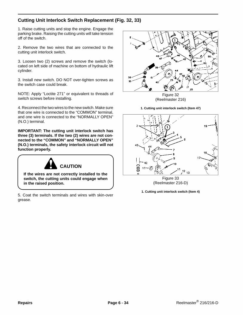
Cutting Unit Interlock Switch Replacement (Fig. 32, 33)
1. Raise cutting units and stop the engine. Engage theparking brake. Raising the cutting units will take tensionoff of the switch.
2. Remove the two wires that are connected to thecutting unit interlock switch.
3. Loosen two (2) screws and remove the switch (lo-cated on left side of machine on bottom of hydraulic liftcylinder.
3. Install new switch. DO NOT over-tighten screws asthe switch case could break.
NOTE: Apply “Loctite 271” or equivalent to threads ofswitch screws before installing.
4. Reconnect the two wires to the new switch. Make surethat one wire is connected to the “COMMON” terminal,and one wire is connected to the “NORMALLY OPEN”(N.O.) terminal.
IMPORTANT: The cutting unit interlock switch hasthree (3) terminals. If the two (2) wires are not con-nected to the “COMMON” and “NORMALLY OPEN”(N.O.) terminals, the safety interlock circuit will notfunction properly.
If the wires are not correctly installed to theswitch, the cutting units could engage whenin the raised position.
5. Coat the switch terminals and wires with skin-overgrease.
Figure 32(Reelmaster 216)
1. Cutting unit interlock switch (Item 47)
Figure 33(Reelmaster 216-D)
1. Cutting unit interlock switch (Item 4)
CAUTION
1
1
Repairs Page 6 - 34 Reelmaster® 216/216-D
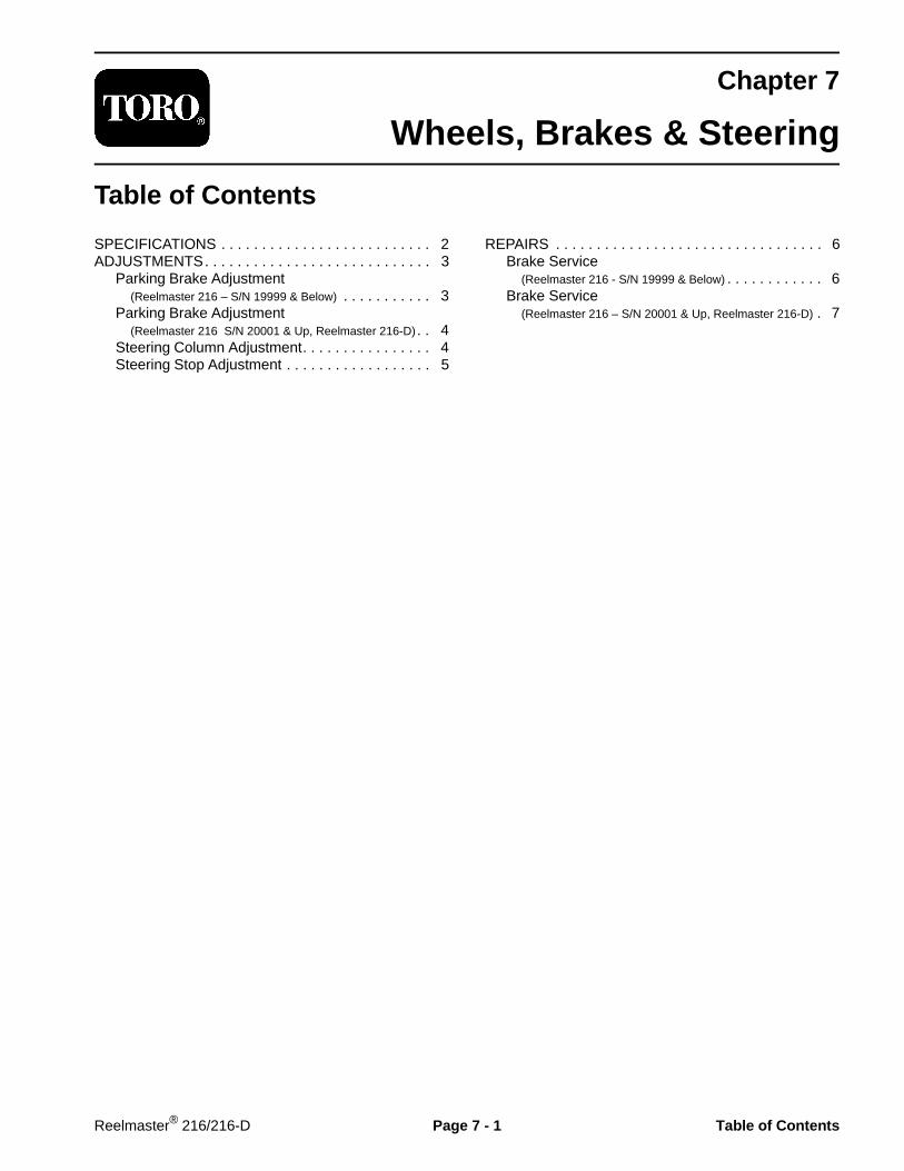
Chapter 7
Wheels, Brakes & Steering
Table of Contents
SPECIFICATIONS . . . . . . . . . . . . . . . . . . . . . . . . . . 2ADJUSTMENTS. . . . . . . . . . . . . . . . . . . . . . . . . . . . 3
Parking Brake Adjustment (Reelmaster 216 – S/N 19999 & Below) . . . . . . . . . . . 3Parking Brake Adjustment (Reelmaster 216 S/N 20001 & Up, Reelmaster 216-D). . 4Steering Column Adjustment. . . . . . . . . . . . . . . . 4Steering Stop Adjustment . . . . . . . . . . . . . . . . . . 5
REPAIRS . . . . . . . . . . . . . . . . . . . . . . . . . . . . . . . . . 6Brake Service (Reelmaster 216 - S/N 19999 & Below) . . . . . . . . . . . . 6Brake Service (Reelmaster 216 – S/N 20001 & Up, Reelmaster 216-D) . 7
Reelmaster® 216/216-D Page 7 - 1 Table of Contents

Specifications
Item Specification__________________________________________________________________________________________
Tire pressure 12 - 16 PSI________________________________________________________________________________________________________________________________________________________
Wheel lug nut torque 45 - 65 ft-lb________________________________________________________________________________________________________________________________________________________
Wheel motor spindle nut torque 250 - 400 ft-lb
Specifications Page 7 - 2 Reelmaster® 216/216-D

Adjustments
Hand Brake Adjustment (Fig. 1)(Reelmaster 216 - S/N 19999 & Below)
Figure 1
1. Jack up front of machine and support under framewith jack stands. Remove both front wheels.
2. Make sure there are four (4) return springs on eachreturn spring bracket.
NOTE: The upper two (2) springs (Item 17) are strongerthan the lower springs (Item 21).
3. Check operation of brake lever and linkage to makesure it moves freely without binding.
4. A properly adjusted brake will have the followingclearances:
A. With handle fully released, left brake shoe shouldrest solidly against upper and lower brake spacersin an approximately centered position.
B. There should be approximately 1/32 in. clearancebetween L.H. brake arm and lug nut (Item 27).
C. Spring (Item 11) should be compressed with thenut to a length of 3/4 in.
D. Right brake shoe should have approximately1/16 in. clearance from upper and lower brake spac-ers in an approximately centered position. Use thefollowing procedure to adjust:
1) Loosen two (2) capscrews (Item 12) on leftbrake arm which hold slide plates (Item 15, 16).2) Put shims between right brake shoe and upperand lower brake spacers.3) While holding left brake shoe against brakespacers, tap slide plates down against roll pin andsecure slide plates in this position.4) Remove shims from behind right brake shoe.
5. Clean any rust or debris from inside of wheel rims.Install wheels and tighten wheel nuts evenly in a cross-ing pattern to a torque of 45 to 65 ft-lb.
6. After any brake adjustment, operate vehicle at lowspeed (one MPH or less) and check that brakes engageequally on both wheels. Adjust again as necessary.
Brake spacers
Reelmaster® 216/216-D Page 7 - 3 Adjustments
Hand Brake Adjustment (Fig. 2)(Reelmaster 216, S/N 20001 & Up, Reelmaster 216-D)
1. Jack up front of machine and support under framewith jack stands. Remove both front wheels.
2. Make sure brake is in OFF position.
3. Loosen jam nut on clevis. Remove cotter pin securingof clevis to lower brake lever. Rotate clevis, one turn ata time, to decrease distance between upper and lowerbrake levers.
4. Install clevis to lower brake lever and tighten jam nut.Repeat procedure on opposite side of machine.
5. Check brake adjustment and adjust again ifnecessary.
6. Install wheels and tighten wheel nuts evenly in acrossing pattern to a torque of 45 to 65 ft-lb.
7. After any brake adjustment, operate vehicle at lowspeed (one MPH or less) and check that brakes engageequally on both wheels. Adjust again as necessary.
Figure 2
1. Lower brake lever2. Clevis
Steering Column Adjustment (Fig. 3)
1. Unlatch and raise hood.
2. Remove capscrew securing steering column to framebracket.
3. Adjust steering column to desired operating positionand install capscrew. Do not use top set of mountingholes in frame bracket.
Figure 3
1. Steering column2. Frame bracket
21
Adjustments Page 7 - 4 Reelmaster® 216/216-D

Steering Stop Adjustment (Fig. 4)
To increase or decrease turning radius of machine whensteering wheel is turned fully left or right, adjust steeringstop screws.
1. Loosen locknuts securing stop screws to tabs onsteering sector.
2. Thread stop screws in or out until desired turningradius is attained.
3. Check adjustment and tighten locknuts.
Figure 4
1. Stop screws2. Steering sector
Reelmaster® 216/216-D Page 7 - 5 Adjustments

Repairs
Brake Service (Fig. 5)(Reelmaster 216 — S/N 19999 & below)
Figure 5
1. Park machine on a level surface. Jack up front ofmachine and support under frame with jack stands.Remove both front wheels.
2. Remove extension springs (Item 17, 21).
3. Remove cotter pin (Item 22). Remove spacer(Item 23), bushing (Item 24) and brake shoe (Item 25)from brake arm.
4. Remove capscrews and lockwashers to remove re-turn spring bracket (Item 20) from brake shoe.
5. Replace parts that are worn or damaged.
6. After installing brake shoes, install extension springs.NOTE: Stronger springs (Item 17) go on top.
7. Do steps 2 - 6 under Hand (Parking) Brake Adjust-ment (Reelmaster 216 - S/N 19999 & Below) in the Adjustmentssection of this chapter.
Repairs Page 7 - 6 Reelmaster® 216/216-D

Brake Service (Fig. 6)(Reelmaster 216 — S/N 20001 & Up, Reelmaster 216-D)
Figure 6
1. Park machine on a level surface. Lift front wheel offthe ground using a jack. Block front and rear of otherwheels.
2. Remove wheel nuts (Item 22) and remove wheel.Remove spindle nut (Item 23) from wheel hub.
3. Mount a wheel puller to wheel mount studs andremove wheel hub (Item 19) and brake drum (Item 18).Remove key (Item 10) from wheel motor shaft.
IMPORTANT: To prevent damage to wheel motor,DO NOT hit wheel hub with a hammer during re-moval or installation.
4. Remove brake shoe springs (Item 17) and brakeshoes (Item 16).
5. Replace worn or damaged parts.
6. After installing brake shoes, install brake shoe springs(Item 17) into holes on each brake shoe plate from theoutside. Springs should be installed in opposite direc-tion of each other.
7. Mount key (Item 10) in wheel motor shaft so top ofkey is in line with taper in shaft, then install wheel huband brake drum.
8. Install spindle nut (item 23) and tighten to a torque of250 - 400 ft-lb.
9. Install wheel and secure with wheel nuts. Tightenwheel nuts evenly in a crossing pattern to a torque of45 to 65 ft-lb.
10. Adjust and check brakes.
Reelmaster® 216/216-D Page 7 - 7 Repairs

Repairs Page 7 - 8 Reelmaster® 216/216-D

Chapter 8
Cutting Unit Drive System
Table of Contents
ADJUSTMENTS. . . . . . . . . . . . . . . . . . . . . . . . . . . . 2Cutting Unit Drive Belt Adjustment . . . . . . . . . . . 2Clutch Adjustment (Reelmaster 216) . . . . . . . . . . . . 3Jackshaft Belt Adjustment (Reelmaster 216) . . . . . . 3Jackshaft Belt Adjustment (Reelmaster 216-D). . . . . 3
REPAIRS . . . . . . . . . . . . . . . . . . . . . . . . . . . . . . . . . 4Clutch Removal and Installation (Reelmaster 216) . 4
Jackshaft and Bearing Service (Reelmaster 216). . . 5Jackshaft, Bearing and Clutch Service (Reelmaster 216) . . . . . . . . . . . . . 6Clutch Service (Reelmaster 216) . . . . . . . . . . . . . . . 8Clutch Service (Reelmaster 216-D) . . . . . . . . . . . . . . 9
Reelmaster® 216/216-D Page 8 - 1 Table of Contents

Adjustments
Cutting Unit Belt Adjustment
Cutting unit drive belts should have a maximum deflec-tion of 1/2 in. with 10 lb. load applied to middle of beltspan.
NOTE: When new belts have been installed, checktension again after the first 8 hours of operation.
Old Style Belt Tensioner Assembly (Fig. 3)
Loosen jam nut on front end of belt tension rod. Rotaterod to lengthen or shorten rod to desired length. Tightenjam nut.
To release belt tension to cutting units:
A. Remove hair pin cotter and pivot belt tension rodhandle outward (away from cutting unit).
B. Turn handle 1/2 turn (180°) so the angle cut(beveled edges) of tension rods are parallel. Belttension is now released.
C. To tighten the belt, turn belt tension rod handle1/2 turn (180°) back to its previous position andinstall hair pin cotter. Angle cuts (beveled edges)must be oriented toward cutting unit and ends mustmake contact when belt is tensioned.
NOTE: For smooth operation, occasionally clean slidingpin at center of tension rod and coat with anti-seizecompound.
NOTE: Old style belt tension rods can be replaced withthe new style assemblies.
New Style Belt Tensioner Assembly (Fig. 4)
Loosen jam nut on front end of belt tension rod. Rotaterod to lengthen or shorten rod to desired length. Tightenjam nut.
To release belt tension to cutting units push retainingcup rearward and pivot yoke downward.
Figure 3(Old Style Belt Tensioner)
1. Belt tension rod handle 3. Jam nut2. Belt tension rod 4. Angle cut
Figure 4(New Style Belt Tensioner)
1. Belt tension rod cup retainer2. Belt tension rod3. Jam nut
Adjustments Page 8 - 2 Reelmaster® 216/216-D

Clutch Adjustment (Reelmaster 216 ) (Fig. 7)
1. Check adjustment by inserting a feeler gauge throughslots next to flange studs on clutch (Item 21).
2. Correct disengaged clearance between clutch platesis 0.006 to 0.012 in. It will be necessary to check thisclearance at each of the three slots to make sure theplates are parallel to each other and equal at all threelocations.
3. Adjust by tightening or loosening locknuts on flangestuds.
Jackshaft Belt Adjustment (Reelmaster 216) (Fig. 5)
NOTE: When a new belt has been installed, checktension again after the first 8 hours of operation.
1. Make sure the idler bracket (Item 11) and belt ten-sioner (Item 6) are free to move.
2. Adjust nut (Item 7) on belt tensioner to compressspring (Item 9) to a length of 3/4 in.
Figure 5
Jackshaft Belt Adjustment (Reelmaster 216-D) (Fig. 6)
NOTE: When a new belt has been installed, checktension again after the first 8 hours of operation.
1. Make sure the idler bracket and belt tension yoke arefree to move.
2. Adjust capscrew to compress spring to a length of3/4 in.
Figure 6
1. Capscrew 2. Spring
1
2
Reelmaster® 216/216-D Page 8 - 3 Adjustments

Repairs
Clutch Replacement (Reelmaster 216) (Fig. 7)
Removing Clutch
1. Loosen tension on jackshaft drive belt (Item 25) andslip belt off of clutch pulley.
2. Disconnect clutch electrical connector.
3. Remove capscrew (Item 24) and washers.
4. Remove clutch (Item 21) from engine shaft.
NOTE: Anti-seize compound is applied to engine shaftat factory. After a period of time anti-seize compoundcan dry up causing clutch to rust to shaft. If this happenstry the following:
1. Apply penetrating oil to loosen the shaft to rotorconnection. Apply penetrating oil to field rotor side ofclutch (side facing engine) and also apply through holein bearing carrier directly to shaft. Be careful not to getexcess lubricant on clutch, especially the armature androtor.
2. Hit bearing collar (on pulley side) a few times toloosen connection between rotor and shaft. Apply morepenetrating oil.
3. Attempt to pull clutch off of shaft by hand. If clutchdoes not come off, use a three-jaw puller. Try have pullerjaws connect as close to bearing as possible. If clutchdoes not come off, apply more penetrating oil, then hitcenter screw on puller a number of times. At this pointsome movement may occur. Apply more penetrating oiland continue trying to pull clutch off shaft.
Installing Clutch
1. Make sure clutch stop (Item 19) is installed in engineblock. Clutch stop should extend 0.75 ± 0.03 inch.Tighten nut (Item 20) to 38 - 32 ft-lb.
2. Install clutch spacer (Item 18) onto engine shaft withCHAMFER TOWARD ENGINE.
3. Install key (Item 36) in shaft keyway. Apply anti-seizecompound to engine shaft and key.
4. Make sure keyways in clutch and pulley are alignedand install clutch onto engine shaft. Make sure clutchstop (Item 19) engages in slot provided in clutch.
5. Secure clutch to engine shaft with capscrew andwashers. Tighten capscrew to a torque of 85 - 90 ft-lb.
6. Check to make sure clutch stop (Item 19) does notcontact any rotating clutch components.
7. Install and adjust jackshaft drive belt.
Figure 7
Rev. A
anti-seizecompound
Repairs Page 8 - 4 Reelmaster® 216/216-D

Jackshaft and Bearing Service ( Reelmaster 216) (Fig. 8)
Figure 8
1. Remove tension from cutting unit drive belts andjackshaft drive belt.
2. With cutting unit belts off pulleys, remove capscrews(Item 19) and locknuts (Item 12) securing bearingmounts (Item 27) to the frame.
3. Slip jackshaft drive belt off electric clutch pulley, lowerjackshaft assembly and slide it from under the machine.
4. Loosen pulley set screws (Item 21). Remove pulleys(Item 22), keys (Item 16), bearing assemblies (Item 25)and locking collars (Item 23) from shaft (Item 20).Toremove eccentric locking collars, loosen setscrew(Item 24) and turn collar in opposite direction from shaftrotation..
5. Inspect bearings (Item 29) and replace if necessary.If replacing bearing, remove bearing assembly (Item 25)from bearing mount (Item 27). Install bearing flanges sogrease zerks are accessible from front of machine onright side and from rear on left side.
NOTE: Old style flangette bearings can be replaced withthe cast housing type bearings used on newer ma-chines.
6. Apply anti-seize compound to keys, then assembleparts to jackshaft. Do not tighten locking collars(Item 23).Do not tighten pulley setscrews.
7. Put belts around pulleys and mount jackshaft assem-bly to frame. Bearing assemblies (Item 25) should bemounted to bearing mounts (Item 27) with nuts (Item 15)snug, but not tightened.
8. Rotate shaft so self-aligning bearings can find theproper alignment position. Tighten bearing mountingnuts. Set eccentric lock collars against bearings byturning lock collars in direction of shaft rotation, thentighten the set screws.
9. Align jackshaft driven pulley so its lead-in side is inline with the clutch pulley within 0.30 in., then tighten setscrew. Align cutting unit pulleys and tighten pulley setscrews.
10. Slip jackshaft drive belt onto electric clutch pulley.Install cutting unit drive belts to cutting unit pulley. Adjusttension of jackshaft drive belt and cutting unit drive belts.
11. Operate machine and observe pulleys and belts inoperation to check for proper alignment. Make surejackshaft drive belt has no tendency to jump grooveswhen engine is run at full speed. Stop engine andre-adjust pulley alignment if necessary.
Reelmaster® 216/216-D Page 8 - 5 Repairs

Jackshaft, Bearing and Clutch Service (Reelmaster 216-D ) (Fig. 9)
Figure 9
1. Remove tension from cutting unit drive belts andjackshaft drive belt.
2. Remove nut (Item 14) and screw (Item 29) securingclutch to clutch retainer.
3. With cutting unit belts off of pulleys, remove cap-screws (Item 5) and locknuts (Item 28) securing bearingsupports (Item 6) to frame. Slip jackshaft drive belt(Item 37) off of clutch pulley (Item 36), lower jackshaftassembly and slide it out from under the machine.
4. Loosen pulley set screws (Item 3). Remove pulleys(Item 4), keys (Item 1), bearing assemblies (Item 7) andlocking collars (Item 9) from shaft (Item 2).To removeeccentric locking collars, loosen setscrew (Item 10) andturn locking collar in opposite direction of shaft rotation.
5. Loosen nut (Item 12). Loosen screws (Item 34).Remove collars (Item 11), sleeve with nut, (Item 40),spacers (Item 35) and clutch/pulley assembly(Item 39, 36)
6. Inspect bearings (Item 8) and replace if necessary. Ifreplacing bearing, remove bearing assembly (Item 7)from bearing support (Item 6). Install bearing flanges sogrease zerks are accessible from front of machine onright side and from rear on left side.
7. Thoroughly clean jackshaft with solvent - degreaserbefore assembling. Apply anti-seize compound to keys,then assemble parts to jackshaft. Do not tighten collars(Item 11) or locking collars (Item 9).Do not tighten pulleysetscrews.
8. Put belts around pulleys and mount jackshaft assem-bly to frame. Bearing assemblies (Item 7) should bemounted to bearing supports (Item 6) with capscrews(Item 31) snug, but not tightened.
9. Rotate shaft so self-aligning bearings can find theproper alignment position. Tighten bearing mountingcapscrews. Set eccentric lock collars against bearingsby turning lock collars in direction of shaft rotation, thentighten the set screws.
Repairs Page 8 - 6 Reelmaster® 216/216-D

10. Align clutch pulley with engine pulley so a straightedge laid across engine pulley face will not have morethan a 0.30 in. gap with flanges on clutch pulley, thentighten collars (Item 11) to secure clutch and pulley inposition. Tighten nut (Item 12) against collar (Item 11)to a torque of 60 - 70 ft-lb.
11. Install screw (Item 29) and nut (Item 14) to secureclutch to clutch retainer.
12. Align cutting unit pulleys and tighten setscrews.
13. Slip jackshaft drive belt onto engine pulley. Installcutting unit drive belts to cutting unit pulleys. Adjusttension of jackshaft drive belt and cutting unit drive belts.
14. Operate machine and observe pulleys and belts inoperation to check for proper alignment. Make surejackshaft drive belt has no tendency to jump grooveswhen engine is run at full speed. Stop engine andre-adjust pulley alignment if necessary.
Figure 10
Tighten nut against collar to 60 - 70 ft-lb
Clutch pulley
Clutch
Reelmaster® 216/216-D Page 8 - 7 Repairs
Clutch Service (Reelmaster 216) (Fig. 11)
The clutch has a rotor that is driven by the enginecrankshaft. When the reel engagement circuit is ener-gized, and electromagnet pulls the armature into con-tact with the rotor to drive the pulley.
Failure to get clutch engagement would likely be causedby a clutch air gap that is too large (see Clutch Adjust-ment), a circuit fault in the clutch electromagnet, or otherelectrical problem (see Troubleshooting section ofChapter 6 - Electrical System).
It is recommended that the clutch be serviced in sub-as-semblies, however, individual parts of the clutch can bereplaced.
1. Remove three (3) locknuts (Item 9) and springs(Item 10).
2. Separate the clutch into two halves: field coil, rotor &bearing assembly (Items 1 - 4) and armature & pulleyassembly (Items 5 - 8, 3).
3. To replace pulley bearings (Item 8):
A. Remove retaining ring (Item 3).
B. Put armature and pulley assembly, pulley sidedown, in an arbor press. Press on bearing collar(Item 7) to remove bearings and collar. If bearingsare removed, they MUST be replaced.
C. Press collar out of bearings.
D. Make sure both inside and outside race of onebearing is on a flat surface and press collar intobearing. Press collar and bearing into other bearing.
E. Put armature and pulley assembly in arbor press,pulley side up. Put spacers in three (3) locationsbetween pulley and armature plate to prevent dam-age to springs. Three (3) stacks of flat washers canbe used for spacers. Make sure extended part ofcollar is facing down and press on outer bearing raceto install bearing and collar.
F. Install retaining ring.
4. Assemble clutch halves, install on engine shaft andadjust air gap. (See Clutch Adjustment and Clutch Re-placement (Reelmaster 216)).
Figure 11
Repairs Page 8 - 8 Reelmaster® 216/216-D

Clutch Service (Reelmaster 216-D) (Fig. 12)
The clutch has a rotor and pulley that is driven from theengine crankshaft by a belt . When the reel engagementcircuit is energized, an electromagnet pulls the armatureinto contact with the rotor to drive the jackshaft.
Failure to get clutch engagement would likely be causedby a clutch air gap that is too large, a circuit fault in theclutch electromagnet, or other electrical problem (seeTroubleshooting section of Chapter 6 - Electrical Sys-tem).
NOTE: The air gap is not adjustable on this clutch.
The clutch must be serviced in sub-assemblies. Individ-ual parts of the clutch can be replaced. See Jackshaft,Bearing and Clutch Service (Reelmaster 216-D) formore information.
Figure 12
1. Field & rotor assembly2. Armature assembly
Reelmaster® 216/216-D Page 8 - 9 Repairs

Repairs Page 8 - 10 Reelmaster® 216/216-D

Chapter 9
Cutting Units
Table of Contents
SPECIFICATIONS . . . . . . . . . . . . . . . . . . . . . . . . . . 2SPECIAL TOOLS . . . . . . . . . . . . . . . . . . . . . . . . . . . 3TROUBLESHOOTING . . . . . . . . . . . . . . . . . . . . . . . 4SET UP AND ADJUSTMENTS. . . . . . . . . . . . . . . . . 6
Adjustment Summary and Checklist . . . . . . . . . . 6Cutting Unit Characteristics. . . . . . . . . . . . . . . . . 7Bedknife to Reel Contact . . . . . . . . . . . . . . . . . . 7Height of Cut Adjustment and Leveling Rear Roller (Floating Cutting Units) . . . . . . . . . . . . . . . . . . . . . . 8Height of Cut Adjustment and Leveling Rear Roller (Fixed Cutting Units) . . . . . . . . . . . . . . . . . . . . . . . 9Parallel Bedknife to Reel . . . . . . . . . . . . . . . . . . 10Verifying Height of Cut Adjustmentand Leveling Front Roller (Floating Cutting Units) . . . . . . . . . . . . . . . . . . . . . . 11Pulley Cleaner Adjustment . . . . . . . . . . . . . . . . . 11Counterbalance Spring Adjustment. . . . . . . . . . . 11
SERVICE AND REPAIRS. . . . . . . . . . . . . . . . . . . . 12Front Roller Installation (Floating Cutting Units) . . . . . . . . . . . . . . . . . . . . . 12Installing Cutting Units (Floating Cutting Units) . . . . . . . . . . . . . . . . . . . . . 13Installing Cutting Units (Fixed Cutting Units). . . . . . . . . . . . . . . . . . . . . . . 13Drive Belt and Belt Tensioner Installation (Floating Cutting Units) . . . . . . . . . . . . . . . . . . . . . 14Drive Belt and Belt Tensioner Installation (Fixed Cutting Units). . . . . . . . . . . . . . . . . . . . . . . 14Counterbalance Spring Installation . . . . . . . . . . 15Cutting Unit Overhaul . . . . . . . . . . . . . . . . . . . . 16Backlapping Cutting Units . . . . . . . . . . . . . . . . . 18
Reelmaster® 216/216-D Page 9 - 1 Table of Contents
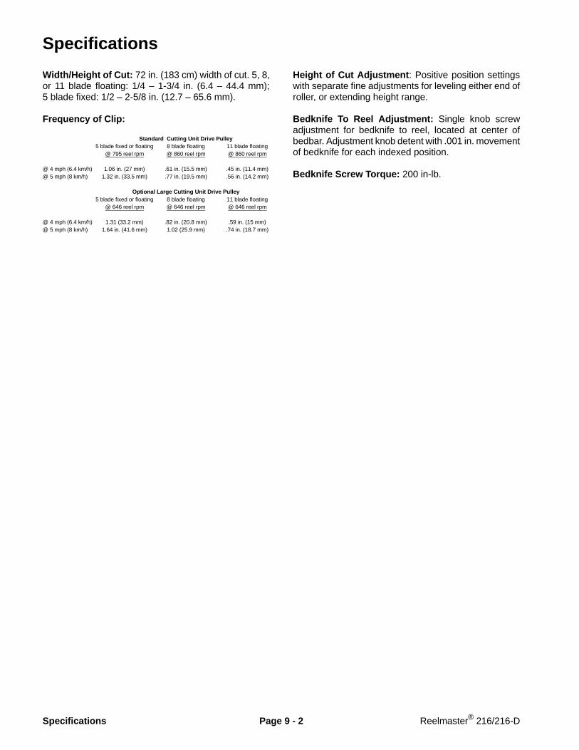
Specifications
Width/Height of Cut: 72 in. (183 cm) width of cut. 5, 8,or 11 blade floating: 1/4 – 1-3/4 in. (6.4 – 44.4 mm);5 blade fixed: 1/2 – 2-5/8 in. (12.7 – 65.6 mm).
Frequency of Clip:
Standard Cutting Unit Drive Pulley5 blade fixed or floating 8 blade floating 11 blade floating
@ 795 reel rpm @ 860 reel rpm @ 860 reel rpm
@ 4 mph (6.4 km/h) 1.06 in. (27 mm) .61 in. (15.5 mm) .45 in. (11.4 mm)@ 5 mph (8 km/h) 1.32 in. (33.5 mm) .77 in. (19.5 mm) .56 in. (14.2 mm)
Optional Large Cutting Unit Drive Pulley5 blade fixed or floating 8 blade floating 11 blade floating
@ 646 reel rpm @ 646 reel rpm @ 646 reel rpm
@ 4 mph (6.4 km/h) 1.31 (33.2 mm) .82 in. (20.8 mm) .59 in. (15 mm)@ 5 mph (8 km/h) 1.64 in. (41.6 mm) 1.02 (25.9 mm) .74 in. (18.7 mm)
Height of Cut Adjustment : Positive position settingswith separate fine adjustments for leveling either end ofroller, or extending height range.
Bedknife To Reel Adjustment: Single knob screwadjustment for bedknife to reel, located at center ofbedbar. Adjustment knob detent with .001 in. movementof bedknife for each indexed position.
Bedknife Screw Torque: 200 in-lb.
Specifications Page 9 - 2 Reelmaster® 216/216-D

Special Tools
NOTE: Order special tools from the TORO SPECIALTOOLS AND APPLICATIONS GUIDE (COMMERCIALPRODUCTS). Some tools may be listed in the Reel-master 216 or Reelmaster 216-D Parts Catalog. Sometools may also be available from a local supplier.
Handle Assembly (Fig. 1)
For applying lapping compound to cutting units whilekeeping hands a safe distance from the rotating reelassembly.
Figure 1
Bedknife Screw Tool (Fig. 2)
Fits Toro bedknife attaching screws. Use with torquewrench to secure bedknife to bedbar. With clean bedbarthreads and new screws, tighten to a torque of 200 in-lb.
NOTE: Remove all rust, scale and corrosion from bed-bar surface before installing bedknife.
DO NOT use an air impact wrench with this tool.
Figure 2
Reelmaster® 216/216-D Page 9 - 3 Special Tools

Troubleshooting
There are a number of factors that can contribute tounsatisfactory quality of cut, some of which may be turfconditions. Turf conditions such as excessive thatch,“sponginess” or attempting to cut off too much grass
height may not always be overcome by adjusting themachine. It is important to remember that the lower theheight of cut, the more critical these factors are.
Factors Affecting Quality of Cut
Factor Possible Problem/Correction__________________________________________________________________________________________
1. Engine maximum governed speed. Check maximum governed engine speed. Adjust tospecification if necessary — affects reel speed.
________________________________________________________________________________________________________________________________________________________
2. Reel speed and ground speed. Select proper reel pulley size and use proper groundspeed to get optimum clip frequency for selectedheight of cut.
See Troubleshooting in Chapter 5 - Hydraulic System.________________________________________________________________________________________________________________________________________________________
3. Tire pressure. Check tire pressure and adjust if necessary. Must beequal in both front tires.
________________________________________________________________________________________________________________________________________________________
4. Reel bearing condition and alignment. Replace bearings if worn or damaged.________________________________________________________________________________________________________________________________________________________
5. Reel and bedknife sharpness. Reel and/or bedknife that has rounded edgeCANNOT be corrected by tightening bedknife to reelcontact. Grind reel to remove taper (cone shape)and/or rifling (grooved or ribbed appearance). Grindbedknife to sharpen and/or remove rifling. (Most com-mon cause of rifling is bedknife to reel contact that istoo tight.)NOTE: New bedknife must be ground after installingon bedbar to match bedknife to bedbar.
________________________________________________________________________________________________________________________________________________________
6. Bedknife parallel to reel. Check and adjust as necessary.________________________________________________________________________________________________________________________________________________________
7. Bedknife to reel contact. Check before operating with cutting unit on ground.Remove belt tension and rotate reel by hand. TURNADJUSTING KNOB ONE (1) CLICK AT A TIME UNTILFIRST CONTACT BETWEEN REEL AND BEDKNIFE ISFELT OR HEARD, THEN TIGHTEN ONE (1) MORECLICK TO GET LIGHT CONTACT. No contact dullscutting edges. Excessive contact increases wear.
Troubleshooting Page 9 - 4 Reelmaster® 216/216-D

Factor Possible Problem/Correction___________________________________________________________________________________________
8. Height of cut. All cutting units set at same height of cut. Bench setheight of cut and actual (effective) height of cut aredifferent. Effective height of cut depends on cuttingunit weight, counterbalance spring adjustment, cut-ting unit accessories and turf conditions.
________________________________________________________________________________________________________________________________________________________
9. Rear roller parallel to reel. Check and adjust as necessary.________________________________________________________________________________________________________________________________________________________
10. Front roller adjustment. Check and adjust as necessary.________________________________________________________________________________________________________________________________________________________
11. Roller scraper and comb adjustment. Set scraper for 1/32 in. clearance from roller. Setcomb the same on all cutting units for height of cutand turf conditions. Must be same height at bothends of comb.
________________________________________________________________________________________________________________________________________________________
12. Stability and position of bedbar. Check bedbar bushings and nylon flange bushingsfor wear or damage and replace if necessary.
Check adjustment knob to make sure detent holdsadjustment. Repair if necessary.
Check to make sure adjustment knob/pivot assemblyis centered in bedbar arm yoke so that an equal gapexists on each side of pivot housing before pivotscrews are installed. Make sure bedknife adjustmentknob/pivot assembly is held firmly in place betweenbedbar arm yoke.Tighten pivot set screws ifnecessary.
________________________________________________________________________________________________________________________________________________________
13. Number of reel blades/reel speed. Use cutting unit model with correct number of bladesand proper pulley size for clip frequency and opti-mum height of cut range.
________________________________________________________________________________________________________________________________________________________
14. Cutting unit alignment. Check alignment on all cutting units. Adjust or repairas necessary. Check lift arms for damage, binding orbushing wear. Repair if necessary.
________________________________________________________________________________________________________________________________________________________
15. Roller condition All rollers must rotate freely. Grease when needed orrepair bearings if necessary.
Reelmaster® 216/216-D Page 9 - 5 Troubleshooting

Set Up and Adjustments
Adjustment Summary and Check List
DETAILED ADJUSTMENT INSTRUCTIONS FOLLOWTHIS SUMMARY AND CHECK LIST. Study this informa-tion and refer to it often to get maximum life and per-formance from the cutting units.
Daily Performance Checks
NOTE: It is not necessary to remove the cutting unitsfrom the traction unit to perform these daily checks. It isrecommended that mowers be washed after each use.Always remove key from ignition switch when workingon the machine.
1. Purge all water and debris from all of the bearings bygreasing them. Use No. 2 multi-purpose lithium basegrease.
2. Visually check for sharp reel and bedknife.
• Remove burrs, nicks, and rounded edges.
3. Lower cutting units to ground (setting on rollers) andremove belt tension. Rotate the reel by hand. TURNADJUSTING KNOB ONE (1) CLICK AT A TIME UNTILFIRST CONTACT BETWEEN REEL AND BEDKNIFE ISFELT AND HEARD THEN TIGHTEN ONE (1) MORECLICK TO GET LIGHT CONTACT *.
• No contact will dull the cutting edges.• Excessive contact accelerates wear; quality of cut may be adversely affected.
* It is best to make the reel to bedknife adjustment in the morning, immediately before each day of mowing.
Weekly Checks
1. Check reel bearing condition — rotate reel by handwith no bedknife to reel contact.
2. Make sure bedknife adjustment knob/pivot assemblyis held FIRMLY in place between bedbar yoke.
3. Using a gauge bar, verify correct height of cut setting.
Monthly Adjustments
NOTE: Remove cutting unit from traction unit.
1. Visually check for sharp reel and bedknife. Backlapor grind reel and bedknife if necessary.
2. Set height of cut adjustment and level rear roller.
3. Adjust bedknife parallel to reel.
5. Floating cutting units only – use gauge bar to verifyheight of cut adjustment and adjust front roller.
6. Adjust roller scraper (if equipped) to 1/32 in. fromroller.
Check to make sure both front and rear rollers con-tact the ground for their entire length and that thebedknife cutting edge is parallel with the ground. Doadjustments again if necessary.
7. Set comb (if equipped) for desired action on turf.
8. After installing cutting units on machine, lower cuttingunits to ground and adjust reel to bedknife contact (seeStep 3 under Daily Performance Checks).
Special Notes
1. Replace the bedbar bushings and nylon flange bush-ings every two years.
2. A “rifled” reel and/or bedknife must be corrected bygrinding.
3. After extended running, a ridge will eventually de-velop at both ends of the bedknife. These ridges mustbe ground off or filed flush with cutting edge of bedknifeto assure smooth operation.
4. Adjust large jam nut on reel shaft to get 0.060 in.clearance from reel blades to end of bedbar whencapscrew on end of reel shaft is tightened. Tightencapscrew on end of reel shaft to 35 ft-lb.
5. To get proper bearing alignment, leave nuts on bear-ing flanges loose and adjust reel parallel to bedknife.Rotate reel by hand and tap end of reel shaft with a softface hammer so self-aligning reel bearings can find theproper alignment position. Tighten nuts to clamp andretain bearings.
*
Set Up and Adjustments Page 9 - 6 Reelmaster® 216/216-D

Cutting Unit Characteristics
The single knob bedknife-to-reel adjustment systemincorporated in this cutting unit simplifies the adjustmentprocedure needed to deliver optimum mowing perform-ance. The precise adjustment possible with the singleknob/bedbar design gives the necessary control to pro-vide a continual self-sharpening action — thus maintain-
ing sharp cutting edges, assuring good quality-of-cut,and greatly reducing the need for routine backlapping.
In addition, the rear roller positioning system permitsoptimum bedknife attitude and location for varyingheight-of-cuts and turf conditions.
Bedknife to Reel Contact (Fig. 3)
Prior to each day’s mowing, or as required, each cuttingunit must be checked to verify proper bedknife-to-reelcontact. This must be performed even though quality ofcut is acceptable.
1. Shut off engine and lower cutting units onto a hardsurface.
2. Release belt tension to cutting units.
3. Slowly rotate reel in reverse direction listening forreel-to-bedknife contact. If no contact is evident, turnbedknife adjusting knob clockwise, one click at a time,until light contact is felt and heard.
4. If excessive contact is felt, turn bedknife adjustingknob counterclockwise, one click at a time until nocontact is evident. Then turn bedknife adjusting knobone click at a time clockwise, until light contact is feltand heard.
IMPORTANT: Light contact is preferred at all times.If light contact is not maintained, bedknife / reeledges will not sufficiently self-sharpen and dullcutting edges will result after a period of operation.If excessive contact is maintained, bedknife / reelwear will be accelerated, uneven wear can result,and quality of cut may be adversely affected.
NOTE: As the reel blades continue to run against thebedknife a slight burr will appear on the front cuttingedge surface the full length of the bedknife. If a file isoccasionally run across the front edge to remove thisburr, improved cutting can be obtained.
After extended running, a ridge will eventually developat both ends of the bedknife. These ridges must beground off or filed flush with cutting edge of bedknife toassure smooth operation.
Figure 3
1. Bedknife adjusting knob
Reelmaster® 216/216-D Page 9 - 7 Set Up and Adjustments

Height of Cut Adjustment and Leveling Rear Roller (Fig. 4)(Floating Cutting Units)
1. Position cutting unit on a flat level table or board.
2. Slightly loosen (crack) nut securing each rollerbracket to angle bracket.
3. Adjust support capscrew to achieve 1-1/16 in. dimen-sion between Height-of-Cut support and front rollerbracket (2 places).
4. Adjust support capscrew to achieve 5/8 ± 1/16 in.dimension between Height-of-Cut support and rearroller bracket (2 places).
5. Remove hair pin cotters securing rear Height-ofCutpins and reinstall in the 1/2 in. setting as indicated onHeight-of-Cut plate.
6. Remove hair pin cotters securing front Height-ofCutpins and reinstall in the 1/4 in. setting as indicated onHeight-of-Cut plate to allow clearance between rollerand table.
7. Position a 1/2 in. or thicker bar under the reel bladesand against the front face of the bedknife. Make surebar covers the full length of reel blades.
8. Verify if rear roller is level, by inserting a piece of paperunder each end of roller.
9. Level roller by adjusting appropriate support cap-screw on rear roller supports until roller is parallel andentire length of roller contacts table.
10. When roller is level, adjust both rollers to desiredposition with Height-of-Cut pins. Tighten nuts securingroller brackets.
Figure 4
1. Roller bracket 4. Support capscrew2. Angle bracket 5. Locknuts3. Height of cut pin
Set Up and Adjustments Page 9 - 8 Reelmaster® 216/216-D

Height of Cut Adjustment and Leveling Rear Roller (Fig. 5)(Fixed Cutting Units)
1. Position cutting unit on flat level surface or board.
2. Slightly loosen (crack) nuts securing roller bracketsto angle brackets.
3. Adjust support capscrews to achieve 5/8 ± 1/16 in.dimension between Height-of-Cut support and rollerbracket (2 places).
4. Remove hairpin cotters securing Height-of-Cut pinsand reinstall in hole at desired setting as indicated onHeight-of-Cut plate.
5. Use a gage block with a height equal to the desiredheight-of-cut and position it against the front edge of thebedknife at one end. Turn the support capscrew toadjust the height of the bedknife equal to the gage block.
6. Repeat the procedure at the other end, then recheckthe original end.
7. Tighten nuts securing roller brackets.
8. After initial set-up, height-of-cut may be changed byrepositioning Height-of-Cut pins to desired setting.
Figure 5
1. Roller bracket2. Angle bracket3. Height of cut pin4. Support capscrew
Reelmaster® 216/216-D Page 9 - 9 Set Up and Adjustments

Parallel Bedknife to Reel (Fig. 6, 7, 8)(Floating or Fixed Cutting Units)
1. Make sure reel contact is removed by turning bed-knife adjustment knob counterclockwise. Tip cutting unitto gain access to reel and bedknife.
2. On either end of reel, insert a long strip of drynewspaper between reel and bedknife. While slowlyrotating reel into bedknife, turn bedknife adjusting knobclockwise, one click at a time until paper is pinchedlightly, which results in a slight drag when paper ispulled.
3. Check for light contact at other end of reel usingpaper. If light contact is not evident, proceed to nextstep.
4. Loosen (2) carriage bolts on bedbar adjuster.
5. Adjust nuts to move bedbar adjuster up or down untilpaper is pinched along entire bedknife surface, whenbedknife adjustment knob is adjusted to no more thantwo clicks beyond first contact of reel bedknife.
6. Tighten nuts and carriage bolts and verify adjustment.
Figure 6
1. Bedknife adjusting knob
Figure 7
Figure 8
1. Bedbar adjuster2. Carriage bolts3. Adjustment nuts
Set Up and Adjustments Page 9 - 10 Reelmaster® 216/216-D

Verifying Height of Cut Adjustment and Leveling Front Roller (Fig. 9)(Floating Cutting Units)
1. On gauge bar, set head of screw to desired Height-of-Cut. This measurement is from bar face to undersideof screw head. Gauge bar (Toro Part No. 13-8199) maybe obtained from your local Toro Distributor.
2. Slightly loosen (crack) nut securing each front rollerbracket to angle bracket.
3. Place the bar across the front and rear rollers andadjust the front roller support screws until the undersideof screw head engages the bedknife cutting edge. Dothis on both ends of reel.
4. Tighten nuts securing roller brackets.Figure 9
1. Gauge bar2. Front roller support screw
Pulley Cleaner Adjustment (Fig. 10)
1. Adjust cleaner bracket so it is centered in groove ofpulley and tighten carriage bolt and locknut.
2. Adjust cleaner bracket so there is approximately.030 – .060 in. clearance between bracket and pulley,then tighten capscrew and locknut.
Figure 10
1. Cleaner bracket
Counterbalance Spring Adjustment
See Counterbalance Spring Installation in Repairs sec-tion of this chapter.
Reelmaster® 216/216-D Page 9 - 11 Set Up and Adjustments
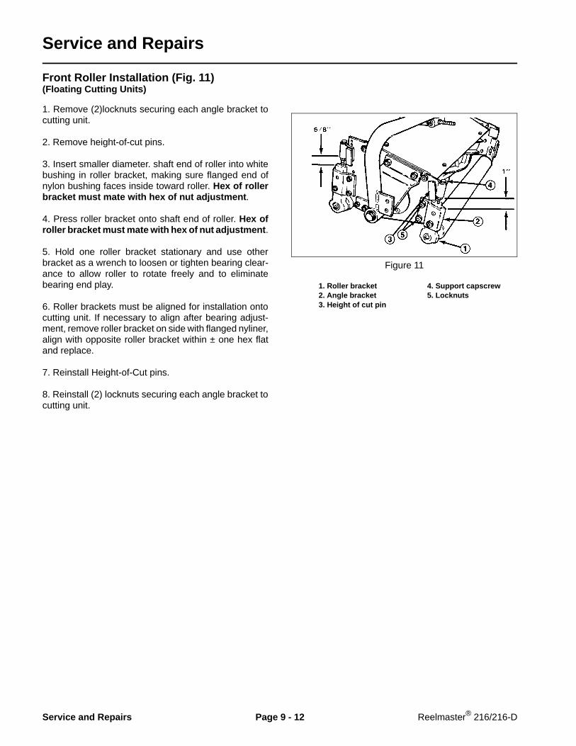
Service and Repairs
Front Roller Installation (Fig. 11)(Floating Cutting Units)
1. Remove (2)locknuts securing each angle bracket tocutting unit.
2. Remove height-of-cut pins.
3. Insert smaller diameter. shaft end of roller into whitebushing in roller bracket, making sure flanged end ofnylon bushing faces inside toward roller. Hex of rollerbracket must mate with hex of nut adjustment .
4. Press roller bracket onto shaft end of roller. Hex ofroller bracket must mate with hex of nut adjustment .
5. Hold one roller bracket stationary and use otherbracket as a wrench to loosen or tighten bearing clear-ance to allow roller to rotate freely and to eliminatebearing end play.
6. Roller brackets must be aligned for installation ontocutting unit. If necessary to align after bearing adjust-ment, remove roller bracket on side with flanged nyliner,align with opposite roller bracket within ± one hex flatand replace.
7. Reinstall Height-of-Cut pins.
8. Reinstall (2) locknuts securing each angle bracket tocutting unit.
Figure 11
1. Roller bracket 4. Support capscrew2. Angle bracket 5. Locknuts3. Height of cut pin
Service and Repairs Page 9 - 12 Reelmaster® 216/216-D

Installing Cutting Units (Fig. 12)(Floating Cutting Units)
1. Slide a thrust washer onto lift arm pivot rod.
2. Slide cutting unit carrier frame onto pivot rod andsecure with a flat washer, lockwasher and capscrew.
Figure 12
1. Thrust washer2. Carrier frame3. Flat washer, lockwasher, capscrew
Installing Cutting Units (Fig. 13)(Fixed Cutting Units)
1. Slide a thrust washer onto lift arm pivot rod.
2. Slide cutting unit support onto pivot rod and securewith a flat washer, lockwasher, and capscrew.
3. Front cutting units should be parallel to front wheels.To adjust, loosen capscrews securing supports to cut-ting units, adjust cutting units until parallel, then, re-tighten screws.
Figure 13
1. Thrust washer2. Cutting unit support3. Flat washer, lockwasher, capscrew
Reelmaster® 216/216-D Page 9 - 13 Service and Repairs

Drive Belt and Belt Tensioner Installation (Fig. 14)(Floating Cutting Units)
1. Route V-belts around jackshaft pulleys and reelpulleys.
2. On pulley end of front cutting units and both ends ofrear cutting unit, remove nut from bolt securing carrierframe to tensioner bracket.
3. Install a spacer,belt tension rod and washer ontocapscrew.
NOTE: Belt tension rods to be in locked position wheninstalling. Loosen jam nut and rotate rod to adjust rodlength for installation.
4. Reinstall nut previously removed. Figure 14
1. Cutting unit drive belt 4. Tensioner bracket 2. Carrier frame 5. Belt tensioner 3. Shoulder bolt, (2) flatwashers, nut
Drive Belt and Belt Tensioner Installation (Fig. 15)(Fixed Cutting Units)
1. Route V-belts around jackshaft pulleys and reelpulleys.
2. On pulley end of front cutting units and both ends ofrear cutting unit, install a washer, spacer, belt tensionrod and spacer on capscrew.
NOTE: Belt tension rods to be in locked position wheninstalling. Loosen jam nut and rotate rod to adjust rodlength for installation.
3. Secure with nut.
Figure 15
1. Tensioner bracket2. Belt tensioner3. Capscrew, (2) flat washers, nut
Service and Repairs Page 9 - 14 Reelmaster® 216/216-D

Counterbalance Spring Installation (Figs. 16, 17, 18)
1. Remove capscrew securing counterbalance arm toframe.
2. Remove hairpin cotter and clevis pin next to arm.
3. Pivot front arms outward and rear arm inward.
4. Hook one end of spring into second hole (frombottom) on cutting unit lift tab.
Note: On rear counterbalance spring install vinyl coverover spring before installing.
5. On front cutting units secure other end of spring toappropriate hole (see chart below) on counterbalancearm with clevis, clevis pin and hairpin cotter.
6. On rear cutting unit secure other end of spring toappropriate hole in counterbalance arm with (2) chainlinks, (5, 8 & 11 Blade Floating Cutting units) or (3) chainlinks (5 Blade Fixed Cutting units), clevis, clevis pin andhairpin cotter.
A. Bottom hole — for 5 blade reel applicationB. Middle hole — for 8 blade reels without basketsC. Top hole — for 8 blade reels using baskets
IMPORTANT: These are recommended settings. Re-adjust spring positions to attain optimum perform-ance. By rais ing spr ing locat ions oncounterbalance arms, cutting unit weight on groundis reduced and traction is increased.
7. To tension the counterbalance springs proceed asfollows:
A. Insert a 3/4 in. socket with long extension bar ontocounterbalance arm pivot hex.
B. Pivot arms back until clevis pin and hairpin cottercan be reinstalled in frame.
C. Reinstall capscrew to lock arms in position.
Use caution when tensioning springs as theyare under heavy load.
Figure 16
1. Counterbalance arm 3. Capscrew, (2 ) flatwashers, 2. Capscrew securing 3. spacer, nut 2. counterbalance arm 4. Counterbalance arm pivot hex
Figure 17
1. Cutting unit lift tab
Figure 18
1. Rear counterbalance spring2. Chain links3. Vinyl cover
CAUTION
Reelmaster® 216/216-D Page 9 - 15 Service and Repairs

Cutting Unit Overhaul (Fig. 19, 20)
Figure 19(8 blade floating cutting unit shown)
It is recommended that the following new parts beinstalled when overhauling a cutting unit. These partsare available in an overhaul kit (Fig. 19):
Rubber bushings (Item 8)Nylon flanged bushings (Item 9)Thrust bearings (Item 18)Seals (Item 20)Bearings (Item 30)Bushing assemblies (Item 38)Flanged bushings (Item 39)Special screws (Item 44)
When assembling cutting unit, apply anti-seize com-pound in the following locations (Fig. 19):
Pivot pins on both ends of bedbar (Item 46).Tapered end of setscrew (Item 49).Stud on bedbar housing (Item 43).Both ends of reel shaft (Item 54).Handle threads (Item 19).Threaded hole in S.P.A. pin (Item 22).To bores before installing bushings (Item 8, 38)Bore of reel bearings (Item 30).
Use Loctite on capscrew (Item 34) that retains pulleyand spacer.
Anti-seizecompound
Loctite
Torque to35 ft-lb
Anti-seizecompound
Anti-seizecompound
Anti-seizecompoundboth ends
Torque to200 in-lb
Anti-seizecompound
Service and Repairs Page 9 - 16 Reelmaster® 216/216-D

When assembling reel (Fig. 19):
Tighten large jam nut (Item 56) on reel shaft againstwasher (Item 57) and bearing (Item 30) so that whencapscrew (Item 34) on end of reel shaft is tightened,there will be a 0.060 in. gap between end of bedbar andreel blades. Tighten capscrew (Item 34) on end of reelshaft to 35 ft-lb.
To get proper bearing alignment, leave nuts (Item 41)on bearing flanges (Item 29, 31) loose and adjust reelparallel to bedknife. Rotate reel by hand and tap eachbearing with a soft-faced hammer so it will self-align inflanges. Tighten nuts to clamp and retain bearings.
When assembling S.P.A. handle (Fig. 19):
Tighten locknut (Item 10) so compression spring(Item 11) is 0.86 in. long.
Pivot (Item 13) must be centered in bedbar arm yoke soa gap exists on both sides of yoke. S.P.A. pin (Item 22)can be moved left or right so handle assembly is straightwith no side load. Tighten hex socket set screws(Item 49) until firmly seated (slight pre-load) in taperedseats, then tighten jam nuts.
Position spring arm (Item 17) and fasten so good solidclicking sound is achieved when turning handle.
Figure 20(Floating cutting unit shown)
When assembling rollers (Fig. 20):
Apply anti-seize compound in the following locations:
Threaded holes on top of brackets (Items 15, 23).To bores before installing bushings (Item 17).
Assemble roller bracket (Item 15), bushing (Item 17)and flanged bushing (Item 16) onto smaller diametershaft end of roller, making sure flanged part of bushingfaces inside towards roller. Press other roller bracketonto opposite shaft end of roller. Hex of roller bracketsmust mate with hex of adjustment nut (Item 19) on roller.
Hold one roller bracket stationary and use oppositeroller bracket as a wrench to loosen or tighten adjust-ment nut (Item 19). Maximum roller rolling torque is5 in-lb after adjustment and installation.
Roller brackets must be aligned for installation ontocutting unit. If necessary to align after bearing adjust-ment, remove roller bracket on side with flanged bush-ing, align with opposite roller bracket within ± one hexflat and replace.
Anti-seizecompound
Anti-seizecompound
Reelmaster® 216/216-D Page 9 - 17 Service and Repairs

Backlapping
The cutting units may be backlapped in position on themachine by releasing tensioning to the drive belts andremoving the capscrew securing the left end of thecarrier frame to the cutting unit. Otherwise, removecutting units completely before backlapping.
Connect a lapping machine to the capscrew on the leftend of reel shaft with an extension coupler and a 9/16 in.socket. Backlap according to procedures in the ToroSharpening Reel and Rotary Mowers Manual Form No.80-300-SL.
Be careful when lapping the reel becausecontact with the reel or other moving partscan result in personal injury.
Under no circumstances use a short handledpaint brush. 29-9100 Handle assembly com-plete or individual parts are available fromyour local Authorized TORO Distributor.
DANGER
CAUTION
Service and Repairs Page 9 - 18 Reelmaster® 216/216-D

This page is blank.

Commercial Products
© The Toro Company