905 656 2 - bauer.de
TRANSCRIPT

Methods
CSMCutter Soil Mixing

Mixing of self-hardening slurries with native soils by using a modified trench cutter technique is an innovative and effective method for constructing cut-off walls, earth retaining walls, foundation elements as well as soil improvement. CSM is used mainly for stabilizing soft or loose soils (non cohesive and cohesive). The equipment used, derived from Bauer’s cutter technology. The applicability of the method is thus extended to much harder strata when compared to other methods of soil mixing.
Main advantages of the method are:
– High productivity – The in-situ soil is used as construction material – Very little generation of spoil (important factor in
contaminated areas) – No vibrations induced during construction – Extended depths (up to 80 m) can be reached –
when using rope-suspended units
2 CSM | © BAUER Maschinen GmbH 7/2021
CSM-Process

Preparation: Excavation of a guide trench for collecting
surplus slurry
Step 1:
Positioning of the cutter head in wall axis. For Kelly-guided systems a guide wall is not required. It is, however, recom-mended for free-hanging systems.
Step 2:
The mixing tool is driven into the ground. At the same time self-hardening slurry or bentonite slurry is added. The soil matrix is broken up by the cutting wheels and liquified by adding slurry. The rotating wheels and cutting teeth push the soil particles through vertically mounted shear plates that have the effect of a compulsory mixer.
Step 3:
After reaching the final depth the mixing tool is extracted while self-hardening slurry is added.
Step 4:
Reinforcing elements required for structural purpose can be inserted into the mixed wall. Therefore, steel beams (mostly H-beams) can be installed into the not yet harde-ned fresh mixed panels. The distance of the beams and beam cross sections are designed on the basis of the applied loads.
3CSM | © BAUER Maschinen GmbH 7/2021
Construction sequence

4 CSM | © BAUER Maschinen GmbH 7/2021
Construction Sequence
One-phase system
Advantages of the one-phase system:
– No auxiliary desanding circuit required – Higher speed of extraction – Preferred application in easy and uniform soils, depth range < 20 m
A continuous wall is formed in a series of overlapping primary and secondary panels. Overcutting into fresh adjacent panels is called „fresh-in-fresh method“.
The cutter technique also allows the “hard-in-hard method”, whereby secondary panels are cut into the already hardened primary panels.
The cutting and mixing procedure can be executed in two ways - in the one-phase or the two-phase system.
During the penetration (downstroke) phase, cutting, mixing, liquifying and homogenising is performed while pumping the binder slurry and compressed air into the soil. As a rule of thumb about 70 % of the total slurry volume is pumped during this phase. The backflow of soil and binder slurry is collected in the pre-excavated trench or stored in a settling pond to be removed off site later.
In the upstroke phase the remaining volume of binder slurry is blended into the soil. The speed of extraction can be higher as the majority of the binder slurry has already been mixed with the soil in the downstroke phase.
P1 S1 P2
2.400 / 2.800 mm
550
– 1.
200
mm
2.400 / 2.800 mm
variable
2.400 / 2.800 mm
Compressor
CSM rigDeliverypump
Trench
Panel
Backhoe
Cementsilo
Bentonitesilo
Agitatorcement
Mixer

5CSM | © BAUER Maschinen GmbH 7/2021
Two-phase system
The soil is liquified and homogenised in the downstroke phase by pumping bentonite slurry or water (in case of clay) into the soil. The backflow of soil and bentonite resp. water can be pumped to a desanding plant where the sand is separated from the slurry which is then pumped back to the rig.
When the backflow becomes too heavy for pumping, it can be removed by a backhoe from the trench onto a mobile coarse screen where primary separation occurs. Using a hose pump the fluid fraction is then pumped to the desanding plant unit for further treatment.
After reaching the final depth, the flow of bentonite resp. water is stopped and replaced by binder. On the upstroke mo-vement cement slurry is mixed thoroughly with the fluidified soil. The speed of extraction and flow of binder are adjusted to ensure that the total calculated quantity of binder is blended with the soil.
Advantages of the two-phase system:
– No risk of getting stuck when working at extended depths or when the working process is interrupted, due to hardening bentonite slurry above the mixing tool
– Wear and tear on the cutting wheels is reduced by using binders
– Preferred application in difficult soil conditions and for extended depth
Hosepump
Soil
Desander
Deliverypump
Agitatorcement
Agitatorbentonite
Mixer
Compressor
Trench
Panel
CSM rig Cementsilo
Bentonitesilo
Hosepump
Soil
Deliverypump
CompressorMobilesieve unit
TrenchBackhoe
Panel
CSM rig
Soil
Desander
Agitatorcement
Agitatorbentonite
Mixer
Cementsilo
Bentonitesilo

6 CSM | © BAUER Maschinen GmbH 7/2021
Productivity Factors
Slurry specifications
The average productivity is highly influenced by the following site parameters
Favourable Unfavourable
Soil structure uniform soil structure layered soil structure
Soil type loose to medium dense sandy silt
dense to very dense soil, cobbles and boulders embedded in soil, stiff or hard soil, cohesive
or organic soil (reduction of the final strength)
Site geometry long, straight wall sections irregular wall layout
Wall depth > 10 mwall depth < 10 m (influence of non-productive
periods such as moving, setting-up)
Main components:
– Cement (OPC or blast furnace cement CEM III/B 32.5) – Water – Bentonite (optional)
Optional additives:
PlasticizerRetarder
Mix design
The mix design should always be determined by suitability tests prior to the start of construction. The following tables give values for an initial design of the mix proportions. They should be used for reference only.
Bentonite suspension
(for fluidifying the soil in the two-phase system) – Approx. 20 – 40 kg bentonite/m3 slurry – 400 l slurry/m3 soil (minimum quantity for fluidifying the soil)
Binder slurry (typical mix design)
Cut-off wall Retaining wall
Cement kg/m3 slurry 250 – 450 750 – 1,200Bentonit kg/m3 slurry 15 – 30 0 – 30w/c ratio 2.0 – 4.0 0.5 – 1.5
The soil conditions:
Particle size distribution, grain size, fines content, organic content, density, SPT values, porosity, groundwater level, chemical contaminations are the main influencing factors in regards to applicability of the system and characteristics of the final product.
Wall characteristics
Cut-off wall Retaining wall
Compressive strength qu 0.5 – 2 5 – 15 MPaPermeability Approx. 1 x 10⁻⁸ m/secCement 100 – 200 200 – 500 kg/m³

Site Examples
Wall construction in limited site conditions
Retaining wall and underpinning for a heritage building CSM wall for start shaft microtunneling
Corner formation retaining wall
7CSM | © BAUER Maschinen GmbH 7/2021

8 CSM | © BAUER Maschinen GmbH 7/2021
CSM-Rigs

BCM Units
9CSM | © BAUER Maschinen GmbH 7/2021
2400
B
B 600
2800
B
B 600
BCM 5 BCM 10
Torque 0 - 50 kNm 0 - 100 kNm
Rotating speed 0 - 40 rpm 0 - 30 rpm
Height 2.35 m 2.8 m
Panel length 2.4 m 2.8 m
Panel width 550 - 1,000 mm 640 -1,200 mm
Weight (with wheels) 5,200 kg 8,200 kg
BCM Cutting and mixing head
Types of wheels
The wheels are designed to cut and loosen the soil matrix and then to mix it with the slurry. The soil type dictates whether more emphasis needs to be put on the wheels’ cutting or mixing capability. The use of symmetrical tooth holders in conjunction with the application of DC teeth allows trouble-free breaking up and mixing of the soil in both rotational directions. A cutter wheel mixing set does consists of four identical mixing wheels.
Four tooth holders in one row of teeth
– Loose to dense non-cohesive soil– Gravelly soil with stones, cohesive soil– Good mixing capacity (due to four tooth holders)
Three tooth holders in one row of teeth
– Dense non-cohesive soil, gravelly soil with stones– Hard cohesive soil – Good cutting capacity (due to three tooth holders)
10 CSM | © BAUER Maschinen GmbH 7/2021
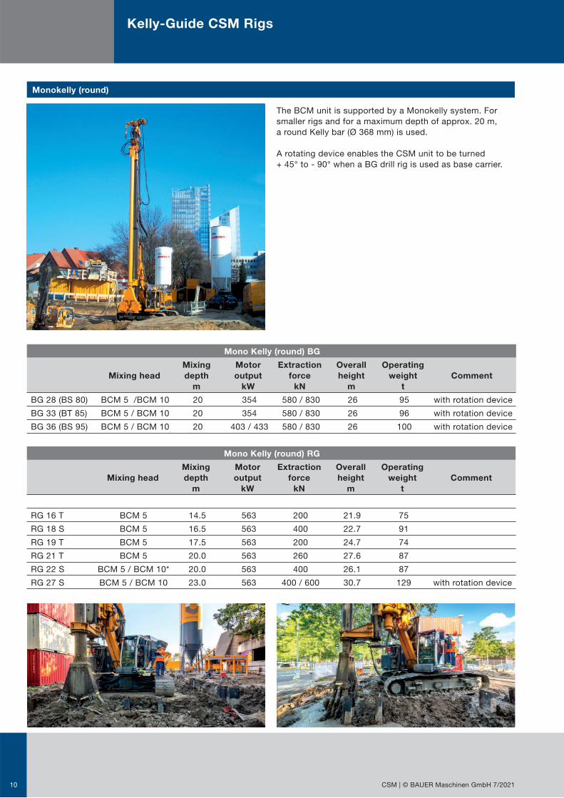
The BCM unit is supported by a Monokelly system. For smaller rigs and for a maximum depth of approx. 20 m, a round Kelly bar (Ø 368 mm) is used.
A rotating device enables the CSM unit to be turned + 45° to - 90° when a BG drill rig is used as base carrier.
Monokelly (round)
Kelly-Guide CSM Rigs
Mono Kelly (round) BG
Mixing head
Mixing
depth
m
Motor
output
kW
Extraction
force
kN
Overall
height
m
Operating
weight
t
Comment
BG 28 (BS 80) BCM 5 /BCM 10 20 354 580 / 830 26 95 with rotation device
BG 33 (BT 85) BCM 5 / BCM 10 20 354 580 / 830 26 96 with rotation device
BG 36 (BS 95) BCM 5 / BCM 10 20 403 / 433 580 / 830 26 100 with rotation device
Mono Kelly (round) RG
Mixing head
Mixing
depth
m
Motor
output
kW
Extraction
force
kN
Overall
height
m
Operating
weight
t
Comment
RG 16 T BCM 5 14.5 563 200 21.9 75
RG 18 S BCM 5 16.5 563 400 22.7 91
RG 19 T BCM 5 17.5 563 200 24.7 74
RG 21 T BCM 5 20.0 563 260 27.6 87
RG 22 S BCM 5 / BCM 10* 20.0 563 400 26.1 87
RG 27 S BCM 5 / BCM 10 23.0 563 400 / 600 30.7 129 with rotation device

11CSM | © BAUER Maschinen GmbH 7/2021
For greater mixing depths, the BCM unit is held and guided by a Mono Kelly with rectangular cross-section (600 x 340 mm). On demand the rectangular Kelly can be extended above the height of the rig mast. The full string length is made of sectional pipes. The connectors are covered with protection shields to ensure a flush surface. Optionally steering plates at the lower end of the Kelly bar can be used.
Mono Kelly (rectangular)
Interlocking system without rotation device
Mixing head
Mixing
depth
m
Motor
output
kW
Extraction
force
kN
Overall
height
m
Operating
weight
t
Comment
BG 28 (BS 80) BCM 5 / BCM 10 35 354 580 / 830 40.8 125
BG 33 (BT 85) BCM 5 / BCM 10 35 354 580 / 830 40.8 126
BG 36 (BS 95) BCM 5 / BCM 10 36 403 / 433 580 / 830 42.8 130
BG 45 (BS 95) BCM 5 / BCM 10 43 433 580 / 820 48.9 174
BG 55 (BS 115) BCM 5 / BCM 10 43 563 460 / 910 48.9 200 on request
RG 27 S BCM 5 / BCM 10 30.5 563 400 / 600 36.5 135
Interlocking system with rotation device
Mixing head
Mixing
depth
m
Motor
output
kW
Extraction
force
kN
Overall
height
m
Operating
weight
t
Comment
BG 28 (BS 80) BCM 5 / BCM 10 35 354 580 / 830 40.8 125
BG 33 (BT 85) BCM 5 / BCM 10 35 354 580 / 830 40.8 126
BG 36 (BS 95) BCM 5 / BCM 10 36 403 / 433 580 / 830 42.8 130
BG 45 (BS 95) BCM 5 / BCM 10 43 433 580 / 820 48.9 174
BG 55 (BS 115) BCM 5 / BCM 10 43 563 460 / 910 48.9 200 on request
BG 72 (BT 180) BCM 5 / BCM 10 53 709 860 60.5 300 on request

12 CSM | © BAUER Maschinen GmbH 7/2021
Rope-Suspended CSM Rigs
2 x BCM 5
Mixing unit (4 gearboxes)
1 x BCM 10
Mixing unit (4 gearboxes)
Quattro Cutter Standard
on MT 75
Tandem Cutter Standard
on MC 64
Quattro Side Cutter
on MT 75
Quattro Side Cutter
on MT 75
Rope-suspended CSM rigs can reach big mixing depths with minimized rig dimensions. The machine concept can be offered in four variants . The basic components are: Base carrier, hose handling system, boom, mixing unit
Quattro Cutter
Tandem Cutter
Quattro Cutter Tandem Cutter
Standard Side Cutter Standard Side Cutter
Hose handling system and boom not turnable turnable not turnable turnable
Overall height (m) 6.6 – 8.1 8.6 6.6 – 8.1 8.6
Working width (m)* 8.0 min. 4.5 8,0 min. 4.5
Max. mixing depth (m) 60 60 80 ** 60
Installed power (kW) 2 x 205 2 x 205 2 x 205 2 x 205
* Width perpendicular to panel axis**80 m on MC 64 base carrier, 60 m on MT 75 base carrier

Mobile sieve unit and hose pumpSlurry Mixing System BAUER MAT CMS-45
13CSM | © BAUER Maschinen GmbH 7/2021
Additional Equipment
Recommended additional equipment for ensuring an efficient working sequence
For one-phase and two-phase system:
– Slurry mixing plant / min. capacity 20 m³/h – Feed pump frequency controlled slurry pump with remote control, capacity depends on volume of panel and speed of
mixing. (typically: 200 – 600 l/min, 12 – 15 bar) – Agitator tank approx. 3 – 5 m3 (as buffer for cement slurry) – Silos for cement and bentonite with screw conveyors – Hydraulic backhoe for excavation of guide trench, maintenance of working platform, handling of backflow – Hoses for conveying cement or bentonite slurry from the agitator to the rig. Typically 1,5” or 2” rubber hose (length to
suit site requirements) – Air compressor – recommended 7 – 14 bar / 7 – 10 m3/min (for air-assisted mixing) – Service crane with vibrator – optional
for inserting universal beam of retaining walls (crane size depends on dimensions of beams)
Additionally for two-phase system:
– Agitator tank as buffer for bentonite slurry – Feed pump – optional pumping of reflux slurry from trench to desanding plant – Desanding plant – optional e. g. BAUER BE 250 – Mobile sieve unit – optional for pre-screening not pumpable, dense reflux slurry

14 CSM | © BAUER Maschinen GmbH 7/2021
Parameters are displayed on the monitor of the rig opera-tor. All CSM rigs are equipped with an electronic control system (B-Tronic).
The B-Tronic system monitors, controls and records production parameters, such as e. g.
– Depth – Quantity and pressure of slurry – Pressure in trench at mixing head height – Inclination (in 2 directions) – Speed of mixing wheels – General rig parameters
All data registered during production can be created and printed for each individual panel in the form of a quality record.
Quality Control
Control of production parameters
Documentation

Obtaining fresh samples using a special sampling tool
Horizontal core sampling with a hand-held drill
Cut-open inner plastic tube with hardened cover Drilling „vertical“ core holes
15CSM | © BAUER Maschinen GmbH 7/2021
In-situ sampling of soil mix material
Quality control of the completed soil mix elements is carri-ed out on samples obtained either before or after the soil/binder slurry mixture has hardened.
Samples of the fresh soil mix material prior to hardening can be obtained by using a special sampling tool.
Insitu samples of hardened soil mix material can be ob-tained by: – Taking “horizontal” core samples with hand-held drills – Drilling “vertical” core holes with drilling rigs used for
exploratory boreholes – Insertion of double-walled plastic tubes into the fresh
soil/slurry mix elements and. after hardening. extraction of the inner tube together with the embedded hardened core

905.656.2 7/2021
Methods
24/724/7
Global Network Service
Equipment Training
International Service Hotline+800 1000 1200* (freecall)+49 8252 [email protected]
* Where available
BAUER Maschinen GmbH BAUER-Strasse 1 86529 Schrobenhausen Germany Tel.: +49 8252 97-0 [email protected] www.bauer.de
Konstruktionsentwicklungen und Prozessverbesserungen können Aktualisierungen und Änderungen von Spezifikation und Materialien ohne vorherige Ankündigung oder Haftung erforderlich machen.Die Abbildungen enthalten möglicherweise optionale Ausstattung und zeigen nicht alle möglichen Konfigurationen. Diese Angaben und die technischen Daten haben ausschließlich Informationscharakter. Irrtum und Druckfehler vorbehalten.
Design developments and process improvements may require the specification and materials to be updated and changed without prior notice or liability. Illustrations may include optional equipment and not show all possible configurations.These and the technical data are provided as indicative information only, with any errors and misprints reserved.