87r-4p compressed air system · 2 6190900 (rev b) 87r-4p compressor system user guide 2017 n-air we...
TRANSCRIPT
Part No. 6190900 (Rev B)
® Registered Trademark/™ Trademark of JUN-AIR Inc. ©Copyright 2017 JUN-AIR Manufacturing Inc. All Rights Reserved.
WWW.JUN-AIR.COMISO 9001 CERTIFIED
87R-4P Compressed Air System
Operation & Maintenance Manual

2
6190900 (Rev B) 87R-4P Compressor System User Guide
© 2017, JUN-AIRWe reserve the right to make any alterations which may be due to any technical improvements
Printed in the USA
Section Page NumberDeclaration of Conformity 3
Table of Symbols 4System Features 5Installation and Operation 7Maintenance 11Troubleshooting 21Warranty Policy 22
WARNINGPLEASE READ THIS MANUAL COMPLETELY BEFORE INSTALLING AND USING
THIS PRODUCT. SAVE THIS MANUAL FOR FUTURE REFERENCE AND
KEEP IN THE VICINITY OF THE PRODUCT.
Dear Customer:
Congratulations on the purchase of your new JUN-AIR Industrial Compressed Air System.
This system’s intended purpose is for industrial and laboratory compression applications. It is to be used in accordance with UL1450/CSA 22.2 standards, along with all applicable codes. The system utilizes an oil-less rocking piston compressor that produces clean, dry, oil-free pressurized air flow when connected to an indus-trial or laboratory device. The tank ensures that a constant supply of air is available to the device.
A pressure regulator and safety relief valve are also included to ensure safe operation of the system. This manual provides installation, operation and preventative maintenance guidelines that should be followed to ensure correct/reliable performance of this system.
Please carry out all maintenance according to relevant instructions.
3© 2017, JUN-AIRWe reserve the right to make any alterations which may be due to any technical improvementsPrinted in the USA
87R-4P Compressor System User Guide 6190900 (Rev B)
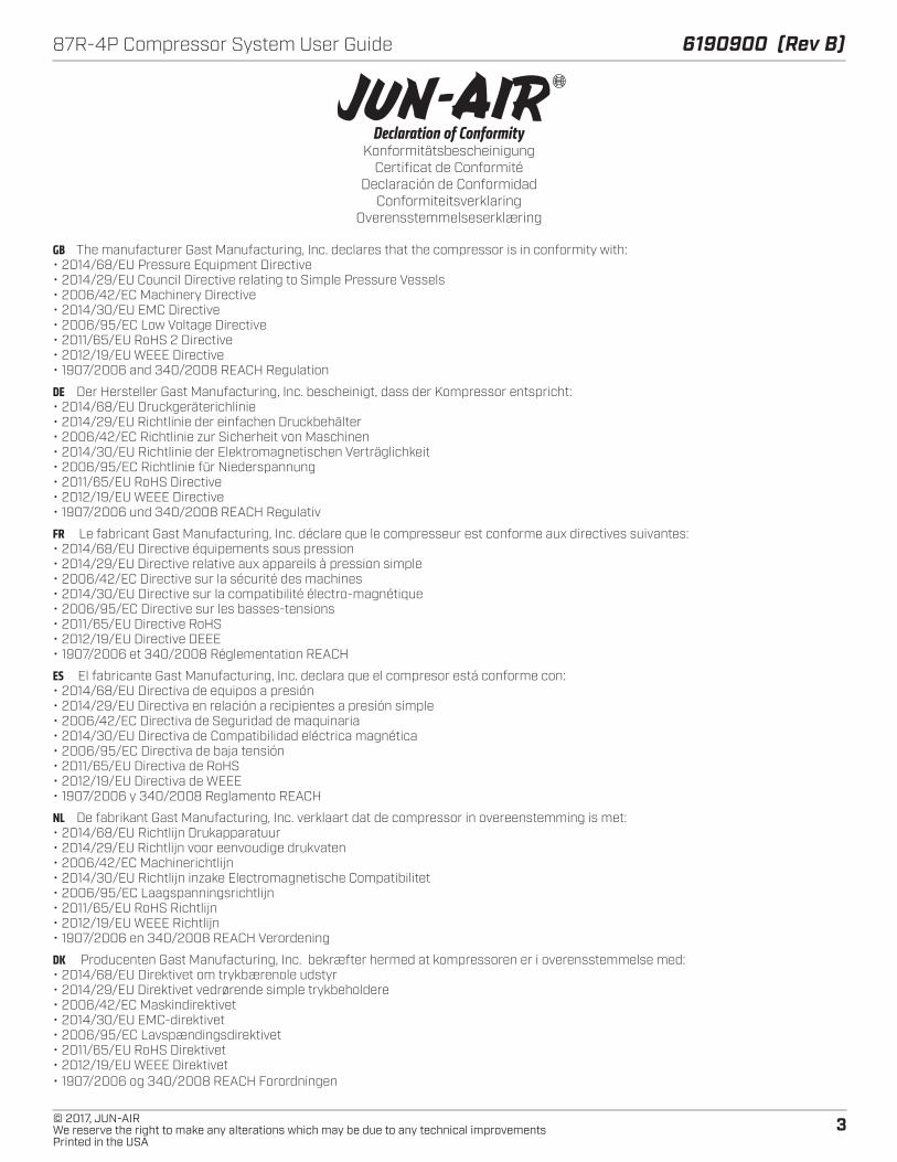
Declaration of ConformityKonformitätsbescheinigung
Certificat de ConformitéDeclaración de Conformidad
ConformiteitsverklaringOverensstemmelseserklæring
GB The manufacturer Gast Manufacturing, Inc. declares that the compressor is in conformity with:• 2014/68/EU Pressure Equipment Directive• 2014/29/EU Council Directive relating to Simple Pressure Vessels• 2006/42/EC Machinery Directive• 2014/30/EU EMC Directive• 2006/95/EC Low Voltage Directive• 2011/65/EU RoHS 2 Directive• 2012/19/EU WEEE Directive• 1907/2006 and 340/2008 REACH Regulation
DE Der Hersteller Gast Manufacturing, Inc. bescheinigt, dass der Kompressor entspricht:• 2014/68/EU Druckgeräterichlinie• 2014/29/EU Richtlinie der einfachen Druckbehälter• 2006/42/EC Richtlinie zur Sicherheit von Maschinen• 2014/30/EU Richtlinie der Elektromagnetischen Verträglichkeit• 2006/95/EC Richtlinie für Niederspannung• 2011/65/EU RoHS Directive• 2012/19/EU WEEE Directive• 1907/2006 und 340/2008 REACH Regulativ
FR Le fabricant Gast Manufacturing, Inc. déclare que le compresseur est conforme aux directives suivantes:• 2014/68/EU Directive équipements sous pression• 2014/29/EU Directive relative aux appareils à pression simple• 2006/42/EC Directive sur la sécurité des machines• 2014/30/EU Directive sur la compatibilité électro-magnétique• 2006/95/EC Directive sur les basses-tensions• 2011/65/EU Directive RoHS• 2012/19/EU Directive DEEE • 1907/2006 et 340/2008 Réglementation REACH
ES El fabricante Gast Manufacturing, Inc. declara que el compresor está conforme con:• 2014/68/EU Directiva de equipos a presión• 2014/29/EU Directiva en relación a recipientes a presión simple• 2006/42/EC Directiva de Seguridad de maquinaria• 2014/30/EU Directiva de Compatibilidad eléctrica magnética• 2006/95/EC Directiva de baja tensión• 2011/65/EU Directiva de RoHS• 2012/19/EU Directiva de WEEE• 1907/2006 y 340/2008 Reglamento REACH
NL De fabrikant Gast Manufacturing, Inc. verklaart dat de compressor in overeenstemming is met:• 2014/68/EU Richtlijn Drukapparatuur• 2014/29/EU Richtlijn voor eenvoudige drukvaten• 2006/42/EC Machinerichtlijn• 2014/30/EU Richtlijn inzake Electromagnetische Compatibilitet• 2006/95/EC Laagspanningsrichtlijn• 2011/65/EU RoHS Richtlijn• 2012/19/EU WEEE Richtlijn• 1907/2006 en 340/2008 REACH Verordening
DK Producenten Gast Manufacturing, Inc. bekræfter hermed at kompressoren er i overensstemmelse med:• 2014/68/EU Direktivet om trykbærenole udstyr• 2014/29/EU Direktivet vedrørende simple trykbeholdere• 2006/42/EC Maskindirektivet• 2014/30/EU EMC-direktivet• 2006/95/EC Lavspændingsdirektivet• 2011/65/EU RoHS Direktivet• 2012/19/EU WEEE Direktivet• 1907/2006 og 340/2008 REACH Forordningen

4
6190900 (Rev B) 87R-4P Compressor System User Guide
© 2017, JUN-AIRWe reserve the right to make any alterations which may be due to any technical improvements
Printed in the USA
TABLE OF SYMBOLS
95 Indicates the acceptable maximumrelative humidity for shipping.
DANGER: Indicates an imminently hazardoussituation which will result in serious or fatalinjury if not avoided. This symbol is used onlyin the most extreme conditions.
WARNING: Indicates a potentially hazardoussituation which could result in serious injuryif not avoided.
Electrical Shock Hazard.Risk of electric shock present. Make sure poweris disconnected before attempting this procedure.
Equipment Alert: Indicates a potentiallyhazardous situation that could result inequipment damage if not avoided.
CAUTION: Indicates a potentially hazardoussituation which may result in minor ormoderate injury if not avoided. It may also beused to alert against unsafe practices.
WARNING: To Avoid Serious Burns.Do not touch surface during operation.
ON OFFIO
Indicates the ON and OFF positionfor the equipment power switch.
Indicates package should be handled withthese symbols pointing up.
FRAGILE: Handle package with care.
Indicates this package must be kept dry.
-28 °C-18 °F
+65 °C+149 °F
Indicates the acceptable shippingtemperature range.372MM HG
.49 ATM
Indicates the acceptable lowest barometricpressure conditions in which this unitcan be shipped.
INDUSTRIAL ELECTRICAL EQUIPMENTWith respect to electrical shock, fire, mechanical,and other specified hazards only in accordancewith UL1450.
Symbol Description
A/C power
Air outlet port
Fuse location
Ground
Hour meter
Over-temp indicator light
Power on indicator light
Pressure gauge
Pressure regulator valve

5© 2017, JUN-AIRWe reserve the right to make any alterations which may be due to any technical improvementsPrinted in the USA
87R-4P Compressor System User Guide 6190900 (Rev B)
SYSTEM FEATURES
Cover
Tank
Compressor
IEC plug& fuse
Power supplyswitch
Airoutlet
Outputpressureregulator
Powerindicatorlight
Over-tempindicator
Hourmeter
Pressureswitch
5 µmautodrain
filter
Systemintake
filter
Drainsolenoid
Dumpsolenoid
Compressorintakefilter
Thermostat
Terminalblock
Heatexchange
6
6190900 (Rev B) 87R-4P Compressor System User Guide
© 2017, JUN-AIRWe reserve the right to make any alterations which may be due to any technical improvements
Printed in the USA
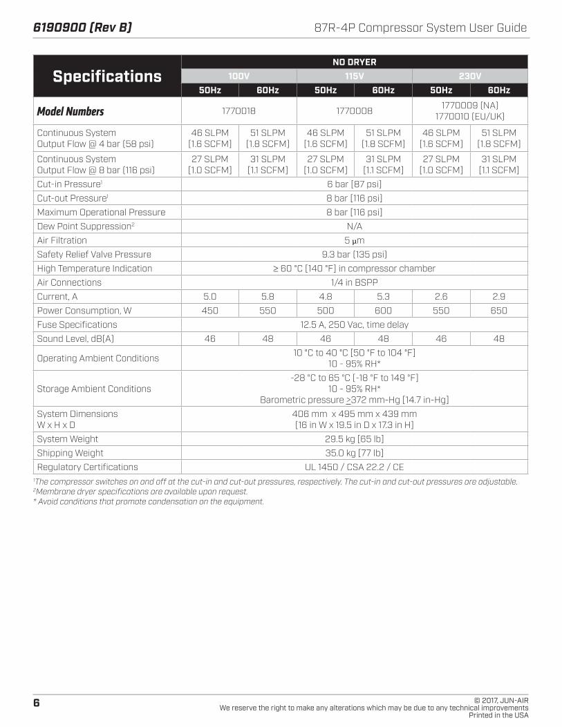
SpecificationsNO DRYER
100V 115V 230V50Hz 60Hz 50Hz 60Hz 50Hz 60Hz
Model Numbers 1770018 1770008 1770009 (NA)1770010 (EU/UK)
Continuous SystemOutput Flow @ 4 bar (58 psi)
46 SLPM [1.6 SCFM]
51 SLPM [1.8 SCFM]
46 SLPM [1.6 SCFM]
51 SLPM [1.8 SCFM]
46 SLPM [1.6 SCFM]
51 SLPM [1.8 SCFM]
Continuous SystemOutput Flow @ 8 bar (116 psi)
27 SLPM [1.0 SCFM]
31 SLPM [1.1 SCFM]
27 SLPM [1.0 SCFM]
31 SLPM [1.1 SCFM]
27 SLPM [1.0 SCFM]
31 SLPM [1.1 SCFM]
Cut-in Pressure1 6 bar [87 psi]
Cut-out Pressure1 8 bar [116 psi]
Maximum Operational Pressure 8 bar [116 psi]
Dew Point Suppression2 N/A
Air Filtration 5 µm
Safety Relief Valve Pressure 9.3 bar (135 psi)
High Temperature Indication ≥ 60 °C [140 °F] in compressor chamber
Air Connections 1/4 in BSPP
Current, A 5.0 5.8 4.8 5.3 2.6 2.9
Power Consumption, W 450 550 500 600 550 650
Fuse Specifications 12.5 A, 250 Vac, time delay
Sound Level, dB(A) 46 48 46 48 46 48
Operating Ambient Conditions 10 °C to 40 °C [50 °F to 104 °F] 10 - 95% RH*
Storage Ambient Conditions-28 °C to 65 °C [-18 °F to 149 °F]
10 - 95% RH*Barometric pressure >372 mm-Hg [14.7 in-Hg]
System Dimensions W x H x D
406 mm x 495 mm x 439 mm [16 in W x 19.5 in D x 17.3 in H]
System Weight 29.5 kg [65 lb]
Shipping Weight 35.0 kg [77 lb]
Regulatory Certifications UL 1450 / CSA 22.2 / CE1The compressor switches on and off at the cut-in and cut-out pressures, respectively. The cut-in and cut-out pressures are adjustable.2Membrane dryer specifications are available upon request.* Avoid conditions that promote condensation on the equipment.

7© 2017, JUN-AIRWe reserve the right to make any alterations which may be due to any technical improvementsPrinted in the USA
87R-4P Compressor System User Guide 6190900 (Rev B)
INSTALLATION AND OPERATION
Intended UseTo provide compressed air for use with industrial or labora-tory devices as a primary or back-up air source.
JUN-AIR compressor systems meet or exceed the most current and highest safety standards, which are:
• UL1450, 4th edition
• CSA C22.2 68
• ISO 9001:2008
• Ingress protection: IP50
• 2006 / 42 / EC Directive
• RoHS compliant
To ensure the safety potential of this equipment is achieved, please:
Make sure your equipment is installed according to the instructions provided in this manual and make sure the installation checklist is completed prior to starting the equipment.
DANGERThe equipment is not suitable for use in the presence of a flammable anesthetic mixture or with oxygen or nitrous oxide. DO NOT OPERATE THE EQUIPMENT IF THESE CONDITIONS EXIST.
Transportation and Storage Conditions• Temperature: -28 °C (-18 °F) to 65 °C (149 °F)
• Relative humidity: 10% to 95%
• Minimum barometric pressure: 372 mm•Hg (14.7 in•Hg)
• Keep the system dry at all times.
• Do not stack units during shipment, installation, or us-age.
Equipment Alert: Refer servicing to an authorized service representative.
Unpacking1. Cut the banding strap from the carton and remove the
lid and cardboard inserts.
2. Visually inspect the entire system for shipping damage and verify that the following accessories have been included: two (2) locking casters, two (2) non-locking casters, four (4) vibration-isolation feet, four (4) studs, four (4) washers, and one (1) power cable.
a. If the contents were damaged during shipping, contact the freight carrier to file a claim.
b. If parts are missing, contact the supplier.
3. Use caution when removing the system from the remaining packaging. Retain the packaging material for future use, if necessary.
4. Install the casters or rubber mounting feet.
Before You Install...
Equipment Alert: Compressors are oil-less andrequire NO lubrication.
Equipment Alert: The system must be installed in a temperature-controlled and/or ventilated room to ensure operational ambient temperature of 50 °F to 104 °F [10 °C to 40 °C]. A 12-inch clearance is required on each side and top of unit to allow air flow. Failure to do so could cause premature loss of system performance and void warranty.
Personal Safety
DANGERRisk of fire or explosion when using flammable substances. Do not operate the system in an area containing combustible gases or anesthetic mixtures.
CAUTIONNever leave children unattended near the system when in use.
WARNINGProperty damage and/or personal injury may result if directions are not followed or if the manufacturer’s replacement parts/accessories are not used.
WARNINGOnly connect equipment suitable for the listed maximum pressure of the system.

8
6190900 (Rev B) 87R-4P Compressor System User Guide
© 2017, JUN-AIRWe reserve the right to make any alterations which may be due to any technical improvements
Printed in the USA
WARNINGDO NOT install the system on a surface with an incline that exceeds 10°.
WARNINGIf unit is operating at a high altitude, adjustments to the duty cycle (on time) or operating pressure may be required. Consult a service technician prior to making any adjustments.
WARNINGA leaking pressure relief valve may indicate a need for adjustment or repair. Consult a service technician prior to making any adjustments.
Protection Against Electrical ShockProvide proper grounding per NFPA 70 (NEC 2008). Do not create a current path from the equipment to ground through your body.
Electrical Safety • Verify that the voltage and frequency specified on the
system are the same as that of the supply power.
• Never operate unit outside the specified voltage range (see “SITE REQUIREMENTS” for range).
• See “SPECIFICATIONS” for more electrical information.
• Indicator light on the system cover displays when sys-tem power is supplied and power switch is on.
Electromagnetic Interference (EMI):The JUN-AIR system is designed to avoid electromagnetic emissions interference with surrounding electrical equipment. Due to the vast assortment of electrical equipment available, it is possible that some interference may be experienced by the end customer. If interference is experienced, the device that is creating interference should be removed from the room where the compressor system is located. If the interference persists, then it may be necessary to confirm that both devices are connected to isolated (separated) circuits per “ELECTRICAL CONNECTIONS” in this manual. If the problem still occurs, then the two devices should be moved as far apart as possible. Finally, if the problem cannot be eliminated, contact JUN-AIR.
CAUTIONRoutinely inspect any and all power cords for cuts and abrasions. Discontinue use and have an authorized service representative replace cord if damaged.
WARNINGUse of an extension cord is not advisable. An undersized extension cord will cause a drop in line voltage and loss of power. Overheating may result. Death or fire from electrical shock could occur.
WARNING
Electric shock could occur as a result of improper grounding. This product must be grounded according to NEC regulations and all local codes
WARNINGAlways switch system off and remove power when servicing or removing the electrical cover. Lock out power at the breaker prior to servicing.
CAUTIONDo not plug into an ungrounded outlet or adapter. Reliable earth ground can only be achieved when system is connected to a grounded receptacle.
WARNING: To Avoid Serious Burns,do not touch surface during operation and allow it to cool prior to servicing.
�WARNING
Electrical Shock Hazard
The grounding wire is indicated by green insulation or green insulation with yellow stripes.
Install this product in a dry location.
Install this product where it will be weather protected.
This product must be properly grounded. Electricallyground this product per local codes.
Check the condition of the power supply wiring.
Do not permanently connect this product to wiring that is not in good condition or is inadequate for the requirements of this product.
Follow all local applied codes prior to installation.
Failure to follow these instructions can resultin death, fire, or electrical shock.
9© 2017, JUN-AIRWe reserve the right to make any alterations which may be due to any technical improvementsPrinted in the USA
87R-4P Compressor System User Guide 6190900 (Rev B)
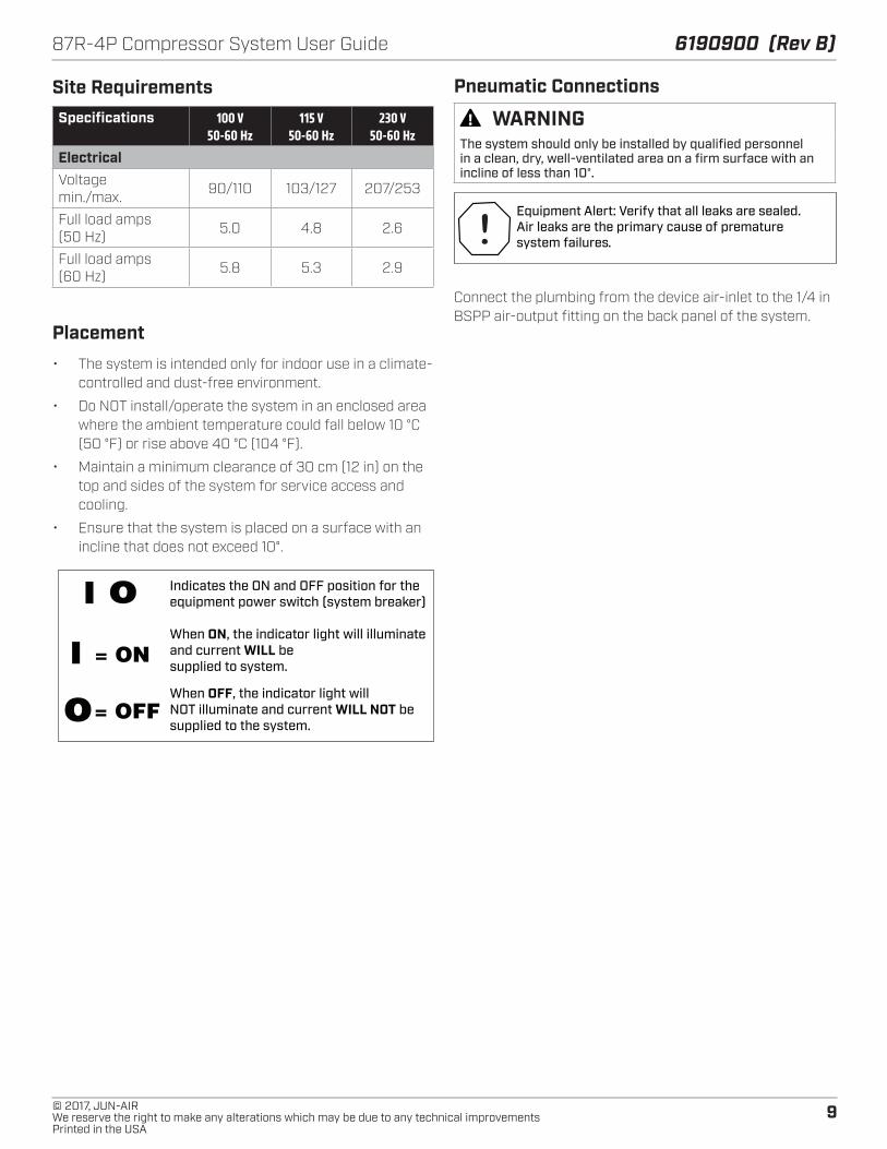
Site Requirements Specifications 100 V
50-60 Hz115 V
50-60 Hz230 V
50-60 HzElectricalVoltage min./max. 90/110 103/127 207/253
Full load amps (50 Hz) 5.0 4.8 2.6
Full load amps (60 Hz) 5.8 5.3 2.9
Placement• The system is intended only for indoor use in a climate-
controlled and dust-free environment.
• Do NOT install/operate the system in an enclosed area where the ambient temperature could fall below 10 °C (50 °F) or rise above 40 °C (104 °F).
• Maintain a minimum clearance of 30 cm (12 in) on the top and sides of the system for service access and cooling.
• Ensure that the system is placed on a surface with an incline that does not exceed 10°.
Indicates the ON and OFF position for the equipment power switch (system breaker)
When ON, the indicator light will illuminate and current WILL be supplied to system.
When OFF, the indicator light will NOT illuminate and current WILL NOT be supplied to the system.
I
o= ON
= OFF
I o
Pneumatic Connections
WARNINGThe system should only be installed by qualified personnel in a clean, dry, well-ventilated area on a firm surface with an incline of less than 10°.
Equipment Alert: Verify that all leaks are sealed. Air leaks are the primary cause of prematuresystem failures.
Connect the plumbing from the device air-inlet to the 1/4 in BSPP air-output fitting on the back panel of the system.
10
6190900 (Rev B) 87R-4P Compressor System User Guide
© 2017, JUN-AIRWe reserve the right to make any alterations which may be due to any technical improvements
Printed in the USA
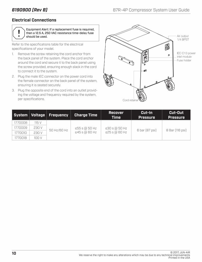
Electrical Connections
Equipment Alert: If a replacement fuse is required, then a 12.5 A, 250 VAC resistance time-delay fuse should be used.
Refer to the specifications table for the electrical specifications of your model.
1. Remove the screw retaining the cord anchor from the back panel of the system. Place the cord anchor around the cord and secure it to the back panel using the screw provided, ensuring enough slack in the cord to connect it to the system.
2. Plug the male IEC connector on the power cord into the female connector on the back panel of the system, ensuring it is seated securely.
3. Plug the opposite end of the cord into an outlet provid-ing the voltage and frequency required by the system, per specifications. Cord retainer
Air output1/4 BPST
Fuse holder
IEC C13 powerinlet module
System Voltage Frequency Charge Time Recover Time
Cut-In Pressure
Cut-OutPressure
1770008 115 V
50 Hz/60 Hz ≤55 s @ 50 Hz ≤45 s @ 60 Hz
≤30 s @ 50 Hz ≤25 s @ 60 Hz 6 bar (87 psi) 8 Bar (116 psi)
1770009 230 V
1770010 230 V
1770018 100 V

11© 2017, JUN-AIRWe reserve the right to make any alterations which may be due to any technical improvementsPrinted in the USA
87R-4P Compressor System User Guide 6190900 (Rev B)
System Checks and Tests
WARNINGAlways switch the system off and disconnect power when removing the system cover.
1. Switch the system power on and verify that the com-pressor runs and the storage tank begins to pressurize.
2. Check the incoming line voltage to verify that it remains within the range specified in the Site Requirements table while the system is running. If the voltage does not remain within the specified range, contact JUN-AIR.
NOTES:
• The safety relief valve is set to 9.3 bar (135 psi).
• The pressure switch is set to cut in at 6 bar (87 psi) and cut out at 8 bar (116 psi). See the specifications table for details.
• Monitor the line-pressure gauge when testing for leaks.
• The tank pressure can be measured using the line pressure gauge by closing the system outlet and ad-justing the regulator knob clockwise until it no longer turns.
• If the tank pressure drops more than 0.5 bar (7.5 psi) in three minutes, air leaks are present. Locate and repair the leak(s).
• Soapy water can be used to check for pressure leaks.
Operation1. When the system is completely installed and ready for
operation, it can be switched on using the power switch on the back panel. A light on the front panel will turn on to indicate that power is supplied to the system and it is operational.
2. The system will provide clean, dry air and has preset cut-in and cut-out pressures of approximately 6 bar (87 psi) and 8 bar (116 psi), respectively. Check the in-ternal tank gauge reading to verify the pressure-switch settings. Contact your authorized dealer before adjust-ing the cut-in/cut-out pressures to values outside the preset range.
3. The pressure of the output air can be adjusted using the regulator knob.
4. When the system is not in use, it should be turned off using the power switch on the back panel. The indicator light on the system cover will turn off when the system is powered down.
WARNINGDischarge pressure in the tank prior to transporting the system or removing connections.
MAINTENANCEPerforming regularly scheduled maintenance will ensure your system provides you with years of superior service.To extend your system’s life, please do the following:
• Keep the system and surrounding area clean and free of debris.
• Maintain the recommended ambient temperature; high temperatures will shorten the life of the system.
• Verify that all leaks are sealed.
Equipment Alert: Indicates a potentiallyhazardous situation that could result inequipment damage if not avoided.
�WARNING
Electrical Shock Hazard
Disconnect electrical power supply cord before performing maintenance on this product
If product is hard wired into system, disconnect electrical power at the circuit breaker or fuse box before performing maintenance on this product.
Failure to follow these instructions can result in death, fire, or electrical shock.
WARNINGInjury Hazard
Product surfaces become very hot during operation,allow product surfaces to cool before handling.
Air stream from product may contain solid or liquidmaterial that can result in eye or skin damage, wear proper eye protection.
Clean this product in a well ventilated area.
Failure to follow these instructions can result in death, fire, or electrical shock.
WARNING: Always disconnect power beforeservicing. Surface(s) can be extremely hot depending on system usage. Do not touch hot parts during or immediately after operation.

12
6190900 (Rev B) 87R-4P Compressor System User Guide
© 2017, JUN-AIRWe reserve the right to make any alterations which may be due to any technical improvements
Printed in the USA
Cleaning or Replacing the System-Intake Filter Element1. Turn the system off and disconnect it from electrical
power.
2. Remove the intake filter element from the system cover and inspect for damage.
3. If cleaning the filter, use warm, soapy water and ensure that it is dry before reinstalling. If replacing the filter, discard the used element.
4. Install the new or cleaned filter element into the system cover, ensuring that it is fully seated the cover.
5. Reconnect electrical power to the system.
NOTE: Filter kits are available for the system (see PARTS AND ACCESSORIES).
Replacing the Autodrain-Filter Element1. Turn the system off and disconnect it from electrical
power.
2. Bleed all of the air from the system.
3. Remove the handle bolts (4) and loosen the cover screws (4) to tilt the cover forward.
4. Rotate the filter bowl and drop it down slightly to re-move it, using caution to avoid damaging or kinking the drain tube.
5. Remove the filter element by turning it completely out, using caution to avoid damaging the plastic element holder. Discard the used filter.
6. Install a new 5 µm filter element after verifying that it is the correct part.
7. Position the filter bowl by pushing up slightly and rotat-ing it into place. Verify that the drain tube is not kinked or damaged.
8. Ensure that the drain tube passes through the base plate and into the evaporator tray.
9. Replace the cover and reinstall the handle bolts and cover screws.
10. Reconnect the electrical power to the system.
Replacing the Evaporator-Tray Element1. Turn the system off and disconnect it from electrical
power.
2. Remove the handle bolts (4) and loosen the cover screws (4) to tip the cover forward.
3. Locate the evaporator tray and remove the foam.
4. Discard the used foam, clean the tray, and install new foam.
5. Replace the cover and reinstall the handle bolts and cover screws.
6. Reconnect the system to electrical power.
Replacing the Compressor-Intake Filter Element1. Turn the system off and disconnect it from electrical
power.
2. Remove the handle bolts (4) and loosen the cover screws (4) to tip the cover forward.
3. Remove the intake filter cap by depressing and rotating it while holding the base of the filter.
4. Remove and discard the used intake filter element.
5. Install a replacement filter element and reinstall the filter cap.
6. Replace the cover and reinstall the handle bolts and cover screws.
7. Reconnect the system to electrical power.
WARNINGDisposal of system components, deemed non-usable by the authorized dealer and the end user, should be done in accordance with all local codes. Contact your local waste management authorities to determine proper disposal methods.
WARNINGDo not exceed the OSHA requirements of 2 bar [29 psig] air for cleaning purposes.

13© 2017, JUN-AIRWe reserve the right to make any alterations which may be due to any technical improvementsPrinted in the USA
87R-4P Compressor System User Guide 6190900 (Rev B)
Pressure-Switch Adjustment
WARNINGExceeding the maximum pressure may result in a reduced system life. Contact Gast Manufacturing for information regarding operation at higher pressure.
Equipment Alert: The factory set cut-in and cut-out pressures are approximately 6 bar (87 psi) and 8 bar (116 psi), respectively.
Equipment Alert: The system should operate at 50% duty cycle or less.
1. Turn the system off and disconnect it from electrical power.
2. Remove the handle bolts (4) and loosen the cover screws (4) to tip the cover forward.
3. Remove the screw retaining the pressure-switch cover and remove the cover.
4. To increase the cut-in pressure, use a 7 mm wrench or socket to turn each of the two nuts on the large springs (A) clockwise; both springs should be adjusted equally. Each half-turn raises the cut-out pressure approxi-mately 0.25 bar (3.5 psi). The cut-in pressure can be reduced by turning the springs in the opposite direc-tion.
5. Set the cut-out pressure by adjusting the pressure dif-ferential (the difference between the cut-in and cut-out pressures). To increase the pressure differential turn the nut on the small spring (B) clockwise. Decrease the pressure differential by turning the nut counter-clock-wise. Ensure that the cut-out pressure does not exceed the maximum rated pressure of the system.
6. Replace and secure the pressure-switch cover to pro-tect against electric shock.
7. Reconnect the system power and charge the tank and verify that the compressor switches off at the desired cut-out pressure. Should the pressure reach 9.3 bar (135 psi) ±3%, the safety relief valve will open and purge the tank.
8. Drain air from the system through the regulator to verify that the compressor switches on at the desired cut-in pressure.
9. Disconnect power and repeat steps 3-8, if necessary.
10. Replace the cover and reinstall the handle bolts and cover screws.
11. Reconnect the system to electrical power.
Pressure Switch ’1’ on or ’O’ off
Adjustment of Pressure Switch Section

14
6190900 (Rev B) 87R-4P Compressor System User Guide
© 2017, JUN-AIRWe reserve the right to make any alterations which may be due to any technical improvements
Printed in the USA
Testing the System for LeaksIt is recommended that leak testing be performed after any maintenance or service.
1. Close the valve to the facility plumbing.
2. Run the system until it reaches the maximum operating pressure—approximately 8 bar (116 psi).
3. Turn the system off.
4. Let the system rest for five minutes.
5. If the pressure drops more than 0.5 bar (7.5 psi) within five minutes, then leaks must be repaired.
6. Use soapy water to locate leaks and repair them as necessary.
7. Open the valve to the facility plumbing.
15© 2017, JUN-AIRWe reserve the right to make any alterations which may be due to any technical improvementsPrinted in the USA
87R-4P Compressor System User Guide 6190900 (Rev B)
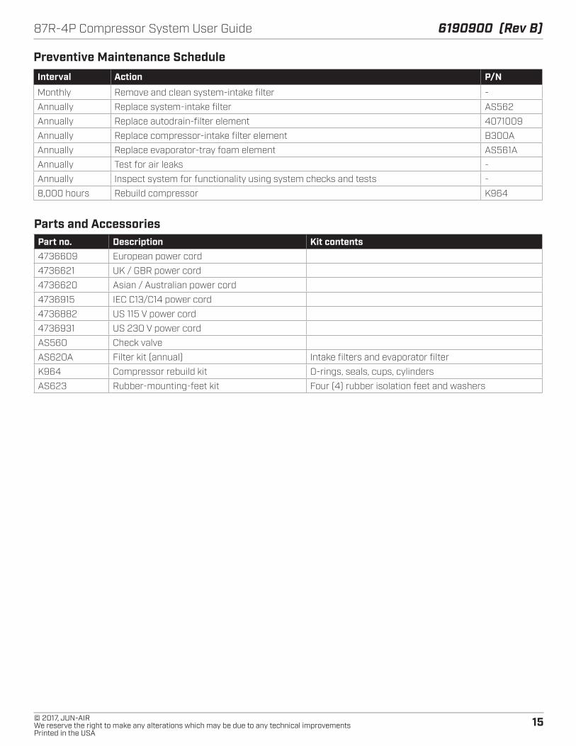
Parts and AccessoriesPart no. Description Kit contents4736609 European power cord
4736621 UK / GBR power cord
4736620 Asian / Australian power cord
4736915 IEC C13/C14 power cord
4736882 US 115 V power cord
4736931 US 230 V power cord
AS560 Check valve
AS620A Filter kit (annual) Intake filters and evaporator filter
K964 Compressor rebuild kit O-rings, seals, cups, cylinders
AS623 Rubber-mounting-feet kit Four (4) rubber isolation feet and washers
Preventive Maintenance ScheduleInterval Action P/N
Monthly Remove and clean system-intake filter -
Annually Replace system-intake filter AS562
Annually Replace autodrain-filter element 4071009
Annually Replace compressor-intake filter element B300A
Annually Replace evaporator-tray foam element AS561A
Annually Test for air leaks -
Annually Inspect system for functionality using system checks and tests -
8,000 hours Rebuild compressor K964

16
6190900 (Rev B) 87R-4P Compressor System User Guide
© 2017, JUN-AIRWe reserve the right to make any alterations which may be due to any technical improvements
Printed in the USA
Mod
el: 1
7700
08

17© 2017, JUN-AIRWe reserve the right to make any alterations which may be due to any technical improvementsPrinted in the USA
87R-4P Compressor System User Guide 6190900 (Rev B) M
odel
s: 1
7700
09 &
17
7001
0

18
6190900 (Rev B) 87R-4P Compressor System User Guide
© 2017, JUN-AIRWe reserve the right to make any alterations which may be due to any technical improvements
Printed in the USA
Mod
el: 1
7700
18
19© 2017, JUN-AIRWe reserve the right to make any alterations which may be due to any technical improvementsPrinted in the USA
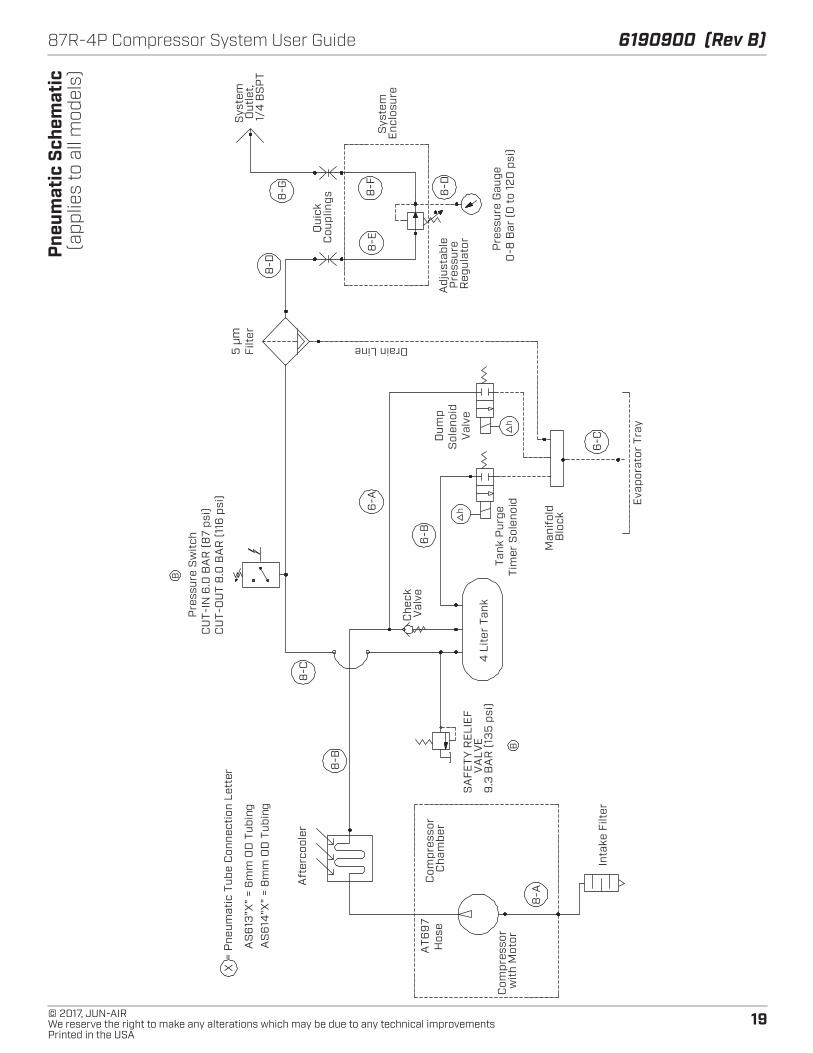
87R-4P Compressor System User Guide 6190900 (Rev B) Pn
eum
atic
Sch
emat
ic(a
pplie
s to
all
mod
els)
Com
pres
sor
wit
h M
otor
Inta
ke F
ilter
Aft
erco
oler
5 µ
mFi
lter
Pre
ssur
e G
auge
0-8
Bar
(0
to
120
psi
)
4 L
iter
Tan
kS
AFE
TY R
ELI
EF
VA
LVE
9.3
BA
R (
135
psi
)
Pre
ssur
e S
wit
chC
UT-
IN 6
.0 B
AR
(8
7 ps
i)C
UT-
OU
T 8
.0 B
AR
(11
6 p
si)
Sys
tem
O
utle
t,
1/4
BS
PT
Drain Line
Adj
usta
ble
Pre
ssur
e R
egul
ator
Dum
pS
olen
oid
Val
ve
Com
pres
sor
Cha
mbe
r
X=
Pne
umat
ic T
ube
Con
nect
ion
Lett
er
Che
ck
Val
ve
AS
613
"X"
= 6
mm
OD
Tub
ing
AS
614
"X"
= 8
mm
OD
Tub
ing
AT6
97
Hos
e
Eva
pora
tor
Tray
Man
ifol
d
Blo
ck
8-B
Tank
Pur
geTi
mer
Sol
enoi
d
Sys
tem
E
nclo
sure
Qui
ck
Cou
plin
gs
6-A
8-A
8-C
8-D
8-G
8-E
8-F
6-B
6-C
6-D
B
h
h
B
20
6190900 (Rev B) 87R-4P Compressor System User Guide
© 2017, JUN-AIRWe reserve the right to make any alterations which may be due to any technical improvements
Printed in the USA
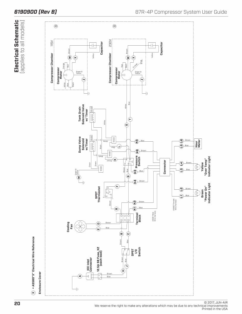
Elec
tric
al S
chem
atic
(app
lies
to a
ll m
odel
s)
Bla
ck
Blu
e
Mot
orC
ompr
esso
r
Com
pres
sor
Cha
mbe
r
X=
AS
580
"X"
Elec
tric
al W
ire
Ref
eren
ce
Con
nect
orIE
C In
let
Met
erH
our
Whi
te
Indi
cato
r Li
ght
"Pow
er O
n"
Gre
en
Sw
itch
I/O
B
lock
Term
inal
Fan
Coo
ling
(eac
h le
ad)
12.5
A S
B F
use,
X2
Ther
mos
tat
SP
DT
Sw
itch
Pre
ssur
e D
PS
T
Indi
cato
r Li
ght
"Ove
r Te
mp"
Ye
llow
w/T
imer
Cap
acit
or
A
K2
K1
HJ
ED
CB
BF
K3
K4
K5
K6
ST
Z
XWG
Brown
Bro
wn
Bro
wn
Blu
e
Blue
Brown
Blu
e
Whi
te
Sol
enoi
d
Yellow
Bro
wn
Yello
wBrown
Blue
Green &
Yello
w
Blu
e
Bro
wn
Blu
e
Bro
wn
Blue
Brown
Blue
Brown
Encl
osur
e C
over
Con
nect
or
L2L1
L4L3
L6L5
Brown
Blue
Blue
Brown
Blue
Brown
Gre
en &
Dum
p V
alve
w/
Tim
er
M
WA
GOG
reen
Gre
en
WA
GO
WA
GO
K
Bla
ck
Black
L
Brown
Blue
Sol
enoi
d V
alve
Wir
e ha
rnes
sA
S58
1 Mal
e
Wir
e ha
rnes
s
Whi
te
WhiteBlue
AS
582
Fem
ale
Mot
or
Com
pres
sor
Cha
mbe
r Cap
acit
or
Z
XW
Com
pres
sor
Yellow
Bro
wn
Yello
w
Red
Ora
nge
Bla
ck
Red
Tank
Dra
in
Green &
Orange
115V
230
V
Ins.
B B
30:0
030
:00
12
3
21© 2017, JUN-AIRWe reserve the right to make any alterations which may be due to any technical improvementsPrinted in the USA
87R-4P Compressor System User Guide 6190900 (Rev B)
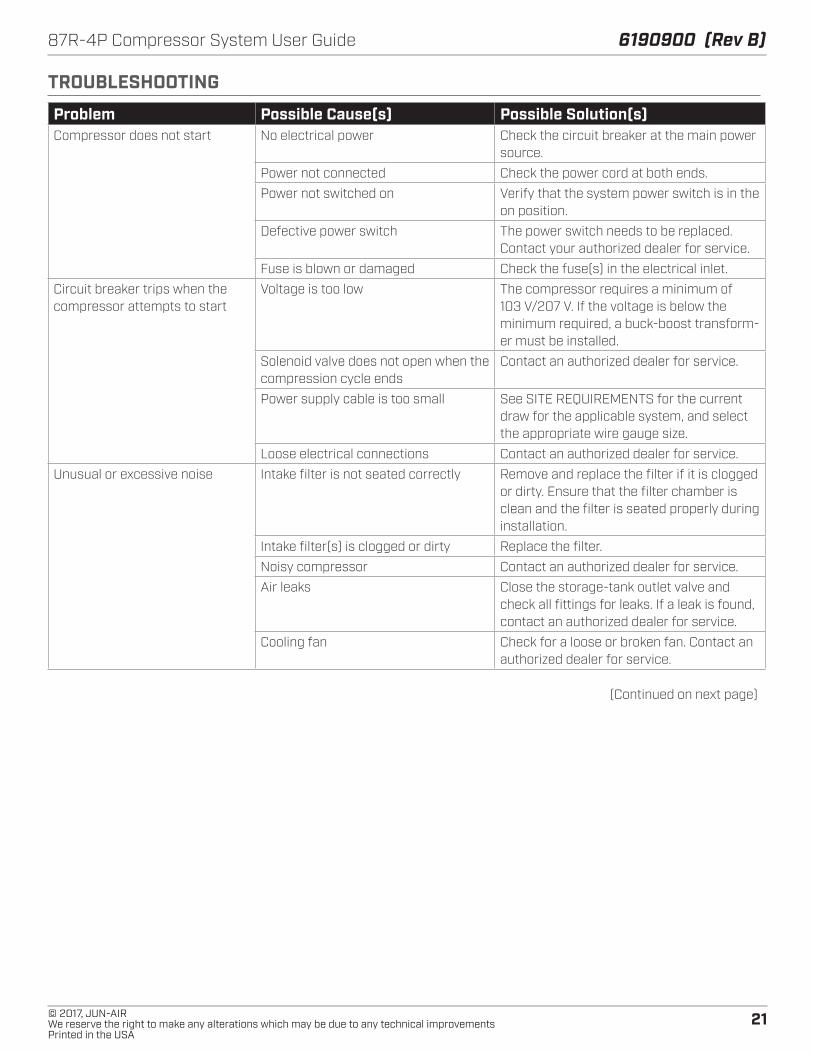
TROUBLESHOOTING
Problem Possible Cause(s) Possible Solution(s)Compressor does not start No electrical power Check the circuit breaker at the main power
source.
Power not connected Check the power cord at both ends.
Power not switched on Verify that the system power switch is in the on position.
Defective power switch The power switch needs to be replaced. Contact your authorized dealer for service.
Fuse is blown or damaged Check the fuse(s) in the electrical inlet.
Circuit breaker trips when the compressor attempts to start
Voltage is too low The compressor requires a minimum of 103 V/207 V. If the voltage is below the minimum required, a buck-boost transform-er must be installed.
Solenoid valve does not open when the compression cycle ends
Contact an authorized dealer for service.
Power supply cable is too small See SITE REQUIREMENTS for the current draw for the applicable system, and select the appropriate wire gauge size.
Loose electrical connections Contact an authorized dealer for service.
Unusual or excessive noise Intake filter is not seated correctly Remove and replace the filter if it is clogged or dirty. Ensure that the filter chamber is clean and the filter is seated properly during installation.
Intake filter(s) is clogged or dirty Replace the filter.
Noisy compressor Contact an authorized dealer for service.
Air leaks Close the storage-tank outlet valve and check all fittings for leaks. If a leak is found, contact an authorized dealer for service.
Cooling fan Check for a loose or broken fan. Contact an authorized dealer for service.
(Continued on next page)
22
6190900 (Rev B) 87R-4P Compressor System User Guide
© 2017, JUN-AIRWe reserve the right to make any alterations which may be due to any technical improvements
Printed in the USA
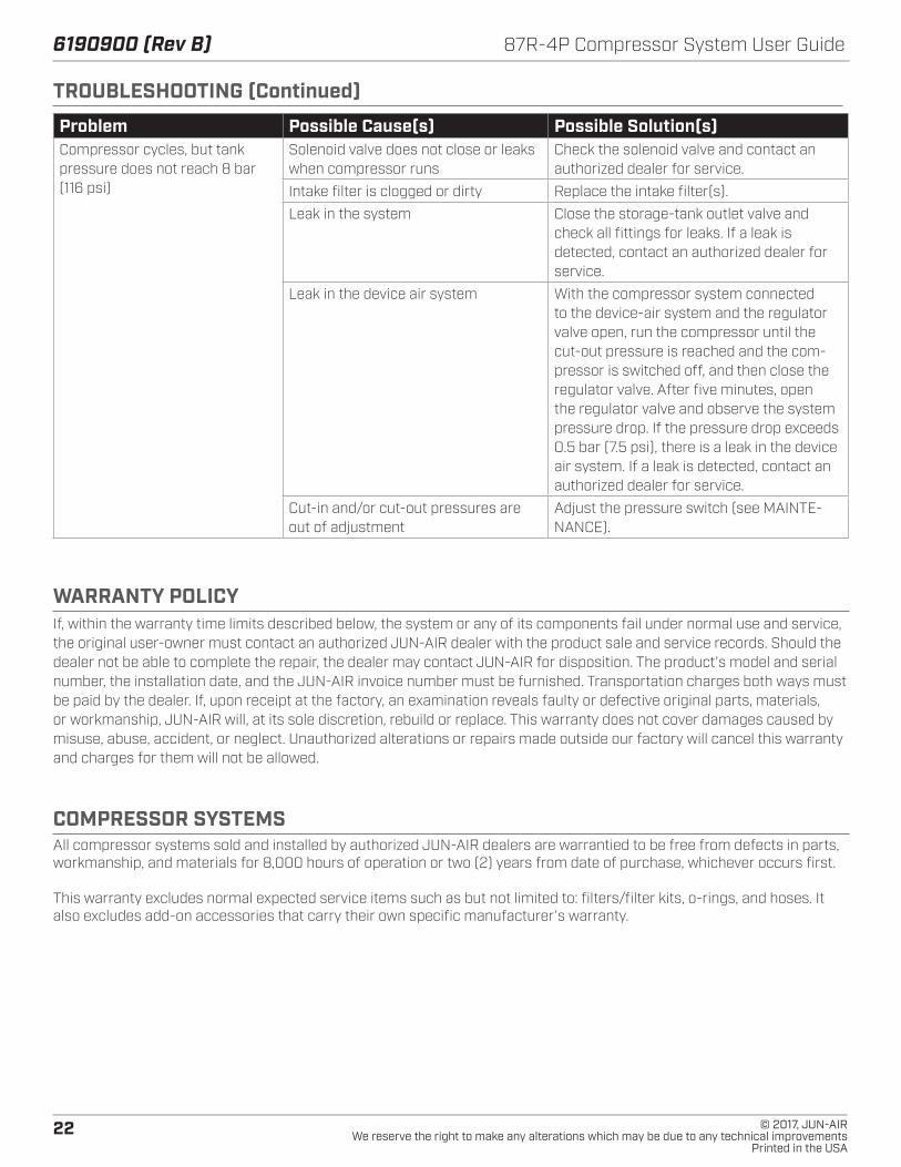
WARRANTY POLICYIf, within the warranty time limits described below, the system or any of its components fail under normal use and service, the original user-owner must contact an authorized JUN-AIR dealer with the product sale and service records. Should the dealer not be able to complete the repair, the dealer may contact JUN-AIR for disposition. The product’s model and serial number, the installation date, and the JUN-AIR invoice number must be furnished. Transportation charges both ways must be paid by the dealer. If, upon receipt at the factory, an examination reveals faulty or defective original parts, materials, or workmanship, JUN-AIR will, at its sole discretion, rebuild or replace. This warranty does not cover damages caused by misuse, abuse, accident, or neglect. Unauthorized alterations or repairs made outside our factory will cancel this warranty and charges for them will not be allowed.
COMPRESSOR SYSTEMSAll compressor systems sold and installed by authorized JUN-AIR dealers are warrantied to be free from defects in parts, workmanship, and materials for 8,000 hours of operation or two (2) years from date of purchase, whichever occurs first.
This warranty excludes normal expected service items such as but not limited to: filters/filter kits, o-rings, and hoses. It also excludes add-on accessories that carry their own specific manufacturer’s warranty.
TROUBLESHOOTING (Continued)
Problem Possible Cause(s) Possible Solution(s)Compressor cycles, but tank pressure does not reach 8 bar (116 psi)
Solenoid valve does not close or leaks when compressor runs
Check the solenoid valve and contact an authorized dealer for service.
Intake filter is clogged or dirty Replace the intake filter(s).
Leak in the system Close the storage-tank outlet valve and check all fittings for leaks. If a leak is detected, contact an authorized dealer for service.
Leak in the device air system With the compressor system connected to the device-air system and the regulator valve open, run the compressor until the cut-out pressure is reached and the com-pressor is switched off, and then close the regulator valve. After five minutes, open the regulator valve and observe the system pressure drop. If the pressure drop exceeds 0.5 bar (7.5 psi), there is a leak in the device air system. If a leak is detected, contact an authorized dealer for service.
Cut-in and/or cut-out pressures are out of adjustment
Adjust the pressure switch (see MAINTE-NANCE).
23© 2017, JUN-AIRWe reserve the right to make any alterations which may be due to any technical improvementsPrinted in the USA
87R-4P Compressor System User Guide 6190900 (Rev B)
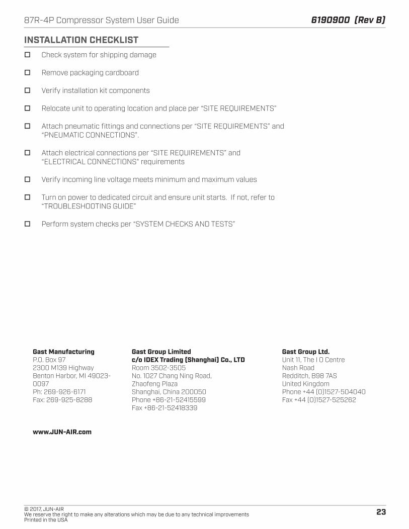
INSTALLATION CHECKLIST o Check system for shipping damage
o Remove packaging cardboard
o Verify installation kit components
o Relocate unit to operating location and place per “SITE REQUIREMENTS”
o Attach pneumatic fittings and connections per “SITE REQUIREMENTS” and “PNEUMATIC CONNECTIONS”.
o Attach electrical connections per “SITE REQUIREMENTS” and “ELECTRICAL CONNECTIONS" requirements
o Verify incoming line voltage meets minimum and maximum values
o Turn on power to dedicated circuit and ensure unit starts. If not, refer to “TROUBLESHOOTING GUIDE”
o Perform system checks per “SYSTEM CHECKS AND TESTS”
Gast ManufacturingP.O. Box 972300 M139 HighwayBenton Harbor, MI 49023-0097Ph: 269-926-6171Fax: 269-925-8288
www.JUN-AIR.com
Gast Group Limitedc/o IDEX Trading (Shanghai) Co., LTDRoom 3502-3505No. 1027 Chang Ning Road, Zhaofeng PlazaShanghai, China 200050Phone +86-21-52415599Fax +86-21-52418339
Gast Group Ltd.Unit 11, The I O CentreNash RoadRedditch, B98 7ASUnited KingdomPhone +44 (0)1527-504040Fax +44 (0)1527-525262