854 quad bender - : the one & only cable
TRANSCRIPT
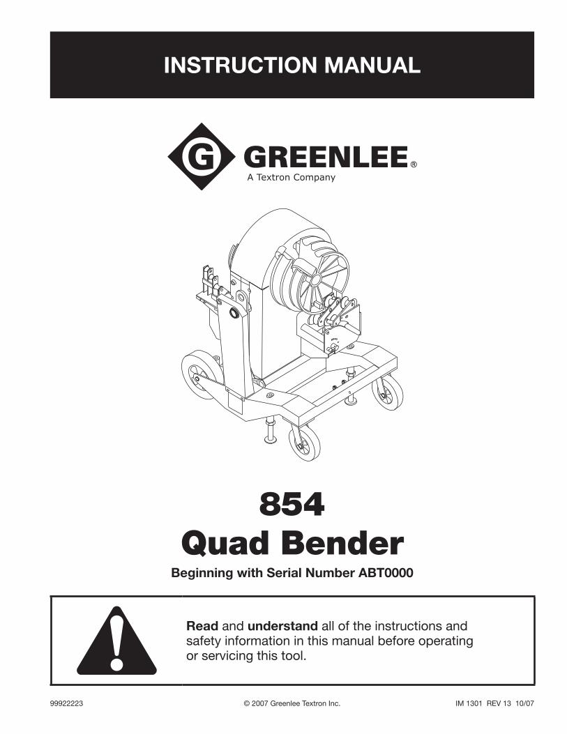
INSTRUCTION MANUAL
854 Quad Bender
Read and understand all of the instructions and safety information in this manual before operating or servicing this tool.
99922223 © 2007 Greenlee Textron Inc. IM 1301 REV 13 10/07
Beginning with Serial Number ABT0000

854 Quad Bender
Greenlee / A Textron Company 4455 Boeing Dr. • Rockford, IL 61109-2988 USA • 815-397-70702
KEEP THIS MANUAL
Table of Contents
Description .................................................................... 2
Safety ............................................................................ 2
Purpose ......................................................................... 2
Important Safety Information .....................................3–4
Grounding Instructions .................................................. 5
Identification .................................................................. 6
Specifications ................................................................ 6
Transportation and Setup .............................................. 7
Operation ....................................................................8–9
Illustrated Bending Glossary ....................................... 10
Bending Instructions ..............................................11–12
Special Bending Information ..................................13–20
Maintenance ...........................................................21–23
Troubleshooting ......................................................24–25
Exploded Views, Parts Lists, Schematics and Wiring Diagrams ..........................26–49
Description
The Greenlee 854 Quad Bender is an electric-powered conduit and pipe bender, intended to make up to 90° bends in 1/2" to 2" conduit and pipe. It is capable of bending the following:
EMT
IMC
Rigid Aluminum
Rigid Steel
40 Mil PVC-Coated Rigid Steel (requires PVC Shoe Group 01700, purchased separately)
Schedule 40 Pipe
Note: This equipment has been tested and found to comply with the limits for a Class A digital device, pursuant to Part 15 of the Federal Communications Commission rules. These limits are designed to provide reasonable protection against harmful interference when the equip-ment is operated in a commercial environment. This equipment generates, uses, and can radiate radio fre-quency energy and, if not installed and used in accordance with the instruction manual, may cause harmful interference to radio communications. Operation of this equipment in a residential area is likely to cause harmful interference, in which case the user will be required to correct the interfer-ence at his own expense.
Do not make any modifications to this device. Unauthorized changes or modifications will void the user’s authority to operate this device under United States federal law.
•
•
•
•
•
•
Safety
Safety is essential in the use and maintenance of Greenlee tools and equipment. This instruction manual and any markings on the tool provide information for avoiding hazards and unsafe practices related to the use of this tool. Observe all of the safety information provided.
Purpose of this Manual
This manual is intended to familiarize personnel with the safe operation and maintenance procedures for the following tool:
854 (03106) Serial Number ABT0000
Keep this manual available to all personnel.
Replacement manuals are available upon request at no charge at www.greenlee.com.
All specifications are nominal and may change as design improvements occur. Greenlee Textron Inc. shall not be liable for damages resulting from misapplication or misuse of its products.
Loctite is a registered trademark of Loctite Corporation.
854 Quad Bender
Greenlee / A Textron Company 4455 Boeing Dr. • Rockford, IL 61109-2988 USA • 815-397-70703
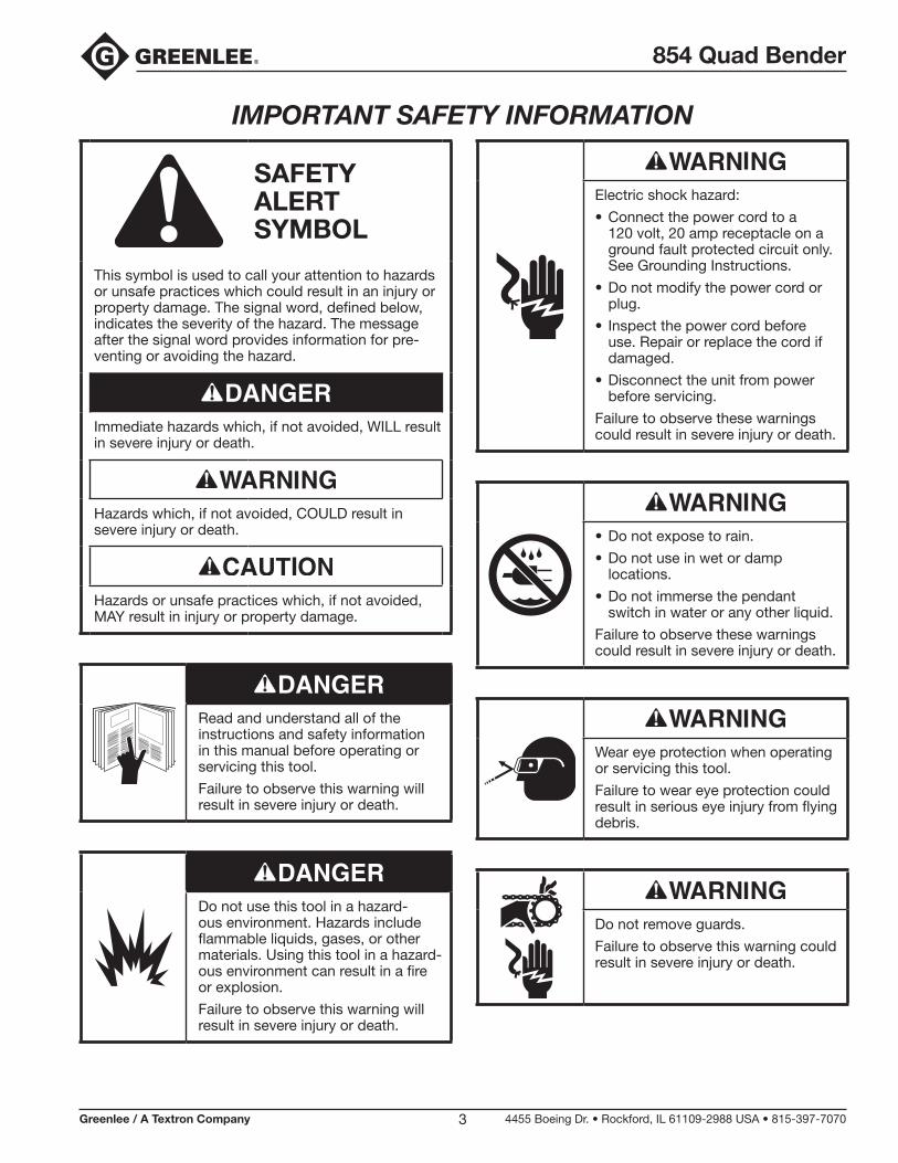
IMPORTANT SAFETY INFORMATION
SAFETY ALERT SYMBOL
This symbol is used to call your attention to hazards or unsafe practices which could result in an injury or property damage. The signal word, defined below, indicates the severity of the hazard. The message after the signal word provides information for pre-venting or avoiding the hazard.
Immediate hazards which, if not avoided, WILL result in severe injury or death.
Hazards which, if not avoided, COULD result in severe injury or death.
Hazards or unsafe practices which, if not avoided, MAY result in injury or property damage.
Read and understand all of the instructions and safety information in this manual before operating or servicing this tool.
Failure to observe this warning will result in severe injury or death.
Do not use this tool in a hazard-ous environment. Hazards include flammable liquids, gases, or other materials. Using this tool in a hazard-ous environment can result in a fire or explosion.
Failure to observe this warning will result in severe injury or death.
Electric shock hazard:
Connect the power cord to a 120 volt, 20 amp receptacle on a ground fault protected circuit only. See Grounding Instructions.
Do not modify the power cord or plug.
Inspect the power cord before use. Repair or replace the cord if damaged.
Disconnect the unit from power before servicing.
Failure to observe these warnings could result in severe injury or death.
•
•
•
•
Do not expose to rain.
Do not use in wet or damp locations.
Do not immerse the pendant switch in water or any other liquid.
Failure to observe these warnings could result in severe injury or death.
•
•
•
Wear eye protection when operating or servicing this tool.
Failure to wear eye protection could result in serious eye injury from flying debris.
Do not remove guards.
Failure to observe this warning could result in severe injury or death.
854 Quad Bender
Greenlee / A Textron Company 4455 Boeing Dr. • Rockford, IL 61109-2988 USA • 815-397-70704
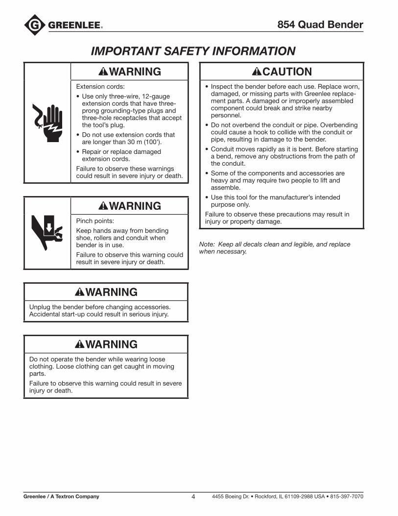
Extension cords:
Use only three-wire, 12-gauge extension cords that have three-prong grounding-type plugs and three-hole receptacles that accept the tool’s plug.
Do not use extension cords that are longer than 30 m (100').
Repair or replace damaged extension cords.
Failure to observe these warnings could result in severe injury or death.
•
•
•
Pinch points:
Keep hands away from bending shoe, rollers and conduit when bender is in use.
Failure to observe this warning could result in severe injury or death.
Unplug the bender before changing accessories. Accidental start-up could result in serious injury.
Do not operate the bender while wearing loose clothing. Loose clothing can get caught in moving parts.
Failure to observe this warning could result in severe injury or death.
IMPORTANT SAFETY INFORMATION
Inspect the bender before each use. Replace worn, damaged, or missing parts with Greenlee replace-ment parts. A damaged or improperly assembled component could break and strike nearby personnel.
Do not overbend the conduit or pipe. Overbending could cause a hook to collide with the conduit or pipe, resulting in damage to the bender.
Conduit moves rapidly as it is bent. Before starting a bend, remove any obstructions from the path of the conduit.
Some of the components and accessories are heavy and may require two people to lift and assemble.
Use this tool for the manufacturer’s intended purpose only.
Failure to observe these precautions may result in injury or property damage.
•
•
•
•
•
Note: Keep all decals clean and legible, and replace when necessary.
854 Quad Bender
Greenlee / A Textron Company 4455 Boeing Dr. • Rockford, IL 61109-2988 USA • 815-397-70705
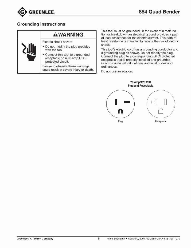
Grounding Instructions
Electric shock hazard:
Do not modify the plug provided with the tool.
Connect this tool to a grounded receptacle on a 20 amp GFCI- protected circuit.
Failure to observe these warnings could result in severe injury or death.
•
•
This tool must be grounded. In the event of a malfunc-tion or breakdown, an electrical ground provides a path of least resistance for the electric current. This path of least resistance is intended to reduce the risk of electric shock.
This tool’s electric cord has a grounding conductor and a grounding plug as shown. Do not modify the plug. Connect the plug to a corresponding GFCI protected receptacle that is properly installed and grounded in accordance with all national and local codes and ordinances.
Do not use an adapter.
20 Amp/120 Volt Plug and Receptacle
ReceptaclePlug
854 Quad Bender
Greenlee / A Textron Company 4455 Boeing Dr. • Rockford, IL 61109-2988 USA • 815-397-70706
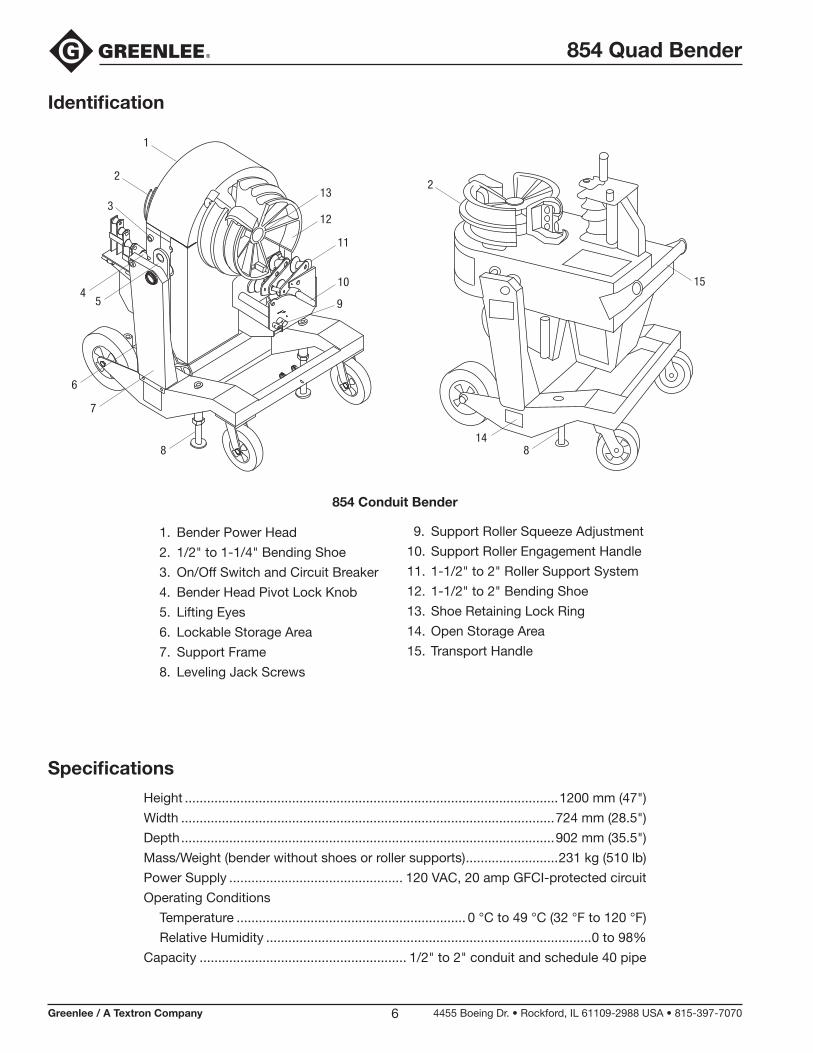
Identification
Specifications
Height .....................................................................................................1200 mm (47")
Width .....................................................................................................724 mm (28.5")
Depth .....................................................................................................902 mm (35.5")
Mass/Weight (bender without shoes or roller supports) .........................231 kg (510 lb)
Power Supply ............................................... 120 VAC, 20 amp GFCI-protected circuit
Operating Conditions
Temperature .............................................................. 0 °C to 49 °C (32 °F to 120 °F)
Relative Humidity ........................................................................................0 to 98%
Capacity ........................................................ 1/2" to 2" conduit and schedule 40 pipe
854 Conduit Bender
1. Bender Power Head
2. 1/2" to 1-1/4" Bending Shoe
3. On/Off Switch and Circuit Breaker
4. Bender Head Pivot Lock Knob
5. Lifting Eyes
6. Lockable Storage Area
7. Support Frame
8. Leveling Jack Screws
9. Support Roller Squeeze Adjustment
10. Support Roller Engagement Handle
11. 1-1/2" to 2" Roller Support System
12. 1-1/2" to 2" Bending Shoe
13. Shoe Retaining Lock Ring
14. Open Storage Area
15. Transport Handle
13
12
11
10
9
2
3
1
54
7
6
8 8
2
14
15

854 Quad Bender
Greenlee / A Textron Company 4455 Boeing Dr. • Rockford, IL 61109-2988 USA • 815-397-70707
Pivoting the Bender Head
The bender head has two bending positions — vertical and horizontal. To change the bender head position:
1. Pull out the bender head pivot lock knob. It may be necessary to twist the knob clockwise until the pin clears the frame.
2. Pivot the bending head to the desired bending position.
3. Push the bender head pivot lock knob back into position so that the pin is fully engaged in the hole.
4. Twist the pivot lock knob counterclockwise until you feel some resistance. Do not tighten it.
Lowering the Jack Screws
The bender is equipped with four jack screws. To park the bender at the jobsite, use the 5/16" T-handle Allen wrench, which is shipped in the lockable storage area, to lower two of the jack screws. If desired, lower all four jack screws to level the bender.
Transportation and SetupHoisting the Bender
To hoist the bender, use either slings (nylon or polyester) or chains with hooks. Each side of the sling or chain must be at least 915 mm (36") long to prevent contact with the bender. All lifting components must be rated for 231 kg (510 lb).
1. Pivot the bending head to the horizontal position with the 1-1/2" to 2" shoe upward (see Pivoting the Bender Head in this section of the manual).
2. Rotate the lifting eyes so they are accessible.
3. Loop the slings through, or attach the hooks to, the lifting eyes.
4. Hoist the bender.
854 Quad Bender
Greenlee / A Textron Company 4455 Boeing Dr. • Rockford, IL 61109-2988 USA • 815-397-70708
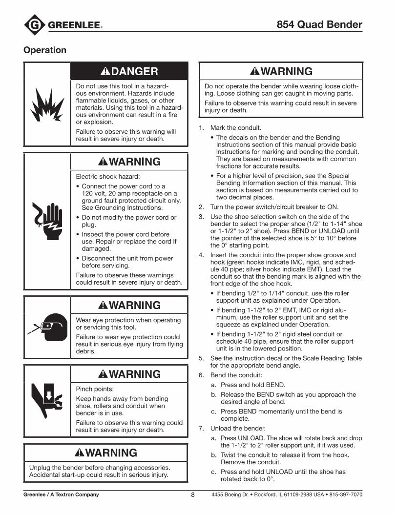
Operation
Do not use this tool in a hazard-ous environment. Hazards include flammable liquids, gases, or other materials. Using this tool in a hazard-ous environment can result in a fire or explosion.
Failure to observe this warning will result in severe injury or death.
Electric shock hazard:
Connect the power cord to a 120 volt, 20 amp receptacle on a ground fault protected circuit only. See Grounding Instructions.
Do not modify the power cord or plug.
Inspect the power cord before use. Repair or replace the cord if damaged.
Disconnect the unit from power before servicing.
Failure to observe these warnings could result in severe injury or death.
•
•
•
•
Wear eye protection when operating or servicing this tool.
Failure to wear eye protection could result in serious eye injury from flying debris.
Pinch points:
Keep hands away from bending shoe, rollers and conduit when bender is in use.
Failure to observe this warning could result in severe injury or death.
Unplug the bender before changing accessories. Accidental start-up could result in serious injury.
Do not operate the bender while wearing loose cloth-ing. Loose clothing can get caught in moving parts.
Failure to observe this warning could result in severe injury or death.
1. Mark the conduit.
The decals on the bender and the Bending Instructions section of this manual provide basic instructions for marking and bending the conduit. They are based on measurements with common fractions for accurate results.
For a higher level of precision, see the Special Bending Information section of this manual. This section is based on measurements carried out to two decimal places.
2. Turn the power switch/circuit breaker to ON.
3. Use the shoe selection switch on the side of the bender to select the proper shoe (1/2" to 1-14" shoe or 1-1/2" to 2" shoe). Press BEND or UNLOAD until the pointer of the selected shoe is 5° to 10° before the 0° starting point.
4. Insert the conduit into the proper shoe groove and hook (green hooks indicate IMC, rigid, and sched-ule 40 pipe; silver hooks indicate EMT). Load the conduit so that the bending mark is aligned with the front edge of the shoe hook.
If bending 1/2" to 1/14" conduit, use the roller support unit as explained under Operation.
If bending 1-1/2" to 2" EMT, IMC or rigid alu-minum, use the roller support unit and set the squeeze as explained under Operation.
If bending 1-1/2" to 2" rigid steel conduit or schedule 40 pipe, ensure that the roller support unit is in the lowered position.
5. See the instruction decal or the Scale Reading Table for the appropriate bend angle.
6. Bend the conduit:
a. Press and hold BEND.
b. Release the BEND switch as you approach the desired angle of bend.
c. Press BEND momentarily until the bend is complete.
7. Unload the bender.
a. Press UNLOAD. The shoe will rotate back and drop the 1-1/2" to 2" roller support unit, if it was used.
b. Twist the conduit to release it from the hook. Remove the conduit.
c. Press and hold UNLOAD until the shoe has rotated back to 0°.
•
•
•
•
•

854 Quad Bender
Greenlee / A Textron Company 4455 Boeing Dr. • Rockford, IL 61109-2988 USA • 815-397-70709
Operation (cont’d)
USING ROLLER SUPPORT UNITS
Use the roller support units to squeeze the conduit as it is bent.
Using the 1/2" to 1-1/4" Roller Support Unit
Pivot this roller support upward and into place when bending all types of 1/2" to 1-1/4" conduit. Pivot the roller support down for easier loading and unloading.
Using the 1-1/2" to 2" Roller Support Unit
Engage this roller support when bending 1-1/2" to 2" EMT, IMC, and rigid aluminum conduit:
1. Load the conduit.
2. While momentarily pressing BEND, move the roller engagement handle up and to the left. The rollers will move up and squeeze the conduit against the shoe. Apply enough force so that the roller support unit contacts the stops before the conduit starts to bend.
Note: If it is difficult to engage the rollers completely, the squeeze is probably set too high. See Adjusting the Squeeze in this section of the manual.
ADJUSTING THE SQUEEZE
When bending 1-1/2" to 2" EMT, IMC, and rigid alumi-num conduit, the roller support must be engaged so that the roller supports the conduit; the pressure against the conduit is the “squeeze”. Setting the squeeze adjust-ment arm to the vertical position (middle hole) provides the necessary amount of squeeze for most 1-1/2" to 2" EMT and IMC conduit.
Due to variations in conduit, the standard adjustment may provide too much or too little squeeze.
If the conduit is difficult to load or develops excessive side marking when bent, the squeeze is set too high.
If the conduit becomes excessively oval or wrinkled, the squeeze is set too low.
To change the amount of squeeze:
1. Loosen the adjustment arm screw.
2. Rotate the adjustment arm one position counter-clockwise to INCREASE the squeeze or one posi-tion clockwise to DECREASE the squeeze.
Note: Decrease the squeeze by three settings when bending rigid aluminum conduit.
3. Align the adjustment arm with one of the holes and tighten the screw.
Changing the squeeze may affect the bending accuracy. If the pointers are inaccurate after changing the squeeze, see Pointer Accuracy under Maintenance.
•
•

854 Quad Bender
Greenlee / A Textron Company 4455 Boeing Dr. • Rockford, IL 61109-2988 USA • 815-397-707010
back-to-back bend — any U-shaped bend formed by two parallel 90° bends with a straight section of conduit or pipe between the bends.
center-to-center distance — the distance between the suc-cessive bends that make up an offset or a three-bend saddle.
developed length — the actual length of pipe that will be bent; see distance “d” in the illustration at left.
gain — the difference between the straight-line distance (a + a) and the shorter radial distance, (d) where:
θ = angle of bend
r = the centerline bending radius of the bending shoe
kick — single bend of less than 90°
leg length — the distance from the end of a straight section of conduit or pipe to the bend; measured from the end to the outside edge of the conduit or pipe.
offset bend — two opposite bends with the same degree of bend; used to avoid an obstruction.
offset height — the distance between the two legs of an offset bend, measured perpendicular to the two legs; also called amount of offset and depth of offset.
rise — the distance from the end of a straight section of conduit or pipe to the bend; measured from the end to the center line of the conduit or pipe. Also called stub or stub-up.
saddle — a three-bend or four-bend combination; used to avoid an obstruction.
shrink — the amount of conduit “lost” when laying out an offset bend working toward an obstruction; see the explanation under Offset Bending in this manual.
springback — the amount, measured in degrees, that a conduit or pipe tends to straighten after being bent.
Illustrated Bending Glossary
a
a
d
r
Offset Height

854 Quad Bender
Greenlee / A Textron Company 4455 Boeing Dr. • Rockford, IL 61109-2988 USA • 815-397-707011
Bending InstructionsSingle Bends (Stubs and Kicks)1. Measure the length of the required stub.2. See the Minimum Stub on the Deduct Table. The
required stub must be equal to or longer than the Minimum Stub.
3. Measure and mark the stub length on the conduit. This is the Stub Length Mark. Subtract the Deduct from this mark and make a new mark. This is Bending Mark 1.
4. Align Bending Mark 1 with the front edge of the hook and bend the conduit.
Note: When the operator presses UNLOAD, the conduit may spring back a few degrees. Compensate by over-bending as shown in the Scale Reading Table.
STUB LENGTHSTUB
LENGTHMARK
BENDINGMARK 1
DEDUCT
STUBLENGTHMARK
BENDINGMARK 1S
TUB
LEN
GTH
Deduct Table
Conduit Size
EMT IMC/Rigid
Deduct Miminum Stub
Deduct Minimum Stub
1/2" 7-1/2 9-1/2 7-1/2 9-1/2
3/4" 9 11 9 11
1" 11 13 11 13
1-1/4" 13-5/8 15-5/8 13-5/8 15-5/8
1-1/2" 14-7/8 16-7/8 14-7/8 16-7/8
2" 16-3/8 18-3/8 16-1/8 18-1/8
Conduit Size Conduit Type Start (0°) 15° 22-1/2° 30° 45° 60° 90°
EMT 1 16-1/2 24 31-1/2 46-1/2 61-1/2 91-1/2
IMC 2-1/2 17-1/2 25-1/2 33 48 63-1/2 93-1/2
1/2" RIG 1 16-1/2 24 31-1/2 46-1/2 61-1/2 91-1/2
AL 1 16 23-1/2 31 46-1/2 61-1/2 91-1/2
PVC 1-1/2 16-1/2 24 31-1/2 46-1/2 61-1/2 91-1/2
EMT 1 16 24 31-1/2 46-1/2 62 92-1/2
IMC 1 16-1/2 24 31-1/2 47 62 92-1/2
3/4" RIG 1/2 15-1/2 23 30-1/2 45-1/2 60-1/2 90-1/2
AL 1/2 15-1/2 23-1/2 31 46 61-1/2 92
PVC 0 15 22-1/2 30 45 60 90
EMT 0 15 22-1/2 30 45-1/2 60-1/2 90-1/2
IMC 2 17 24-1/2 32 47 62 92-1/2
1" RIG 1 16 23-1/2 31 46 61 91
AL 1/2 15-1/2 23-1/2 31 46 61-1/2 91-1/2
PVC 1/2 15-1/2 23 30-1/2 45-1/2 60-1/2 90-1/2
EMT 1 16 23-1/2 31-1/2 46-1/2 61-1/2 92
IMC 2 17-1/2 25 32-1/2 47-1/2 62-1/2 92-1/2
1-1/4" RIG 1 16 23-1/2 31 46 60-1/2 90-1/2
AL 1-1/2 16-1/2 24 31-1/2 46-1/2 61-1/2 91-1/2
PVC 1/2 15-1/2 23 30-1/2 45-1/2 60-1/2 90-1/2
EMT 1 16 24 31-1/2 46-1/2 61-1/2 92
IMC 2 17 25 32-1/2 47-1/2 63 93-1/2
1-1/2" RIG 0 15 22-1/2 30 45 60 90-1/2
AL 1 16 23-1/2 31 46 61-1/2 91-1/2
PVC 1/2 16 23-1/2 31 46 61 91
EMT 1/2 15 22-1/2 30 45 59-1/2 89
IMC 3-1/2 18-1/2 26 33-1/2 48-1/2 63-1/2 94
2" RIG 1 16 23-1/2 31 45-1/2 60-1/2 90-1/2
AL 2 17 24-1/2 32 47 61-1/2 91-1/2
PVC 2 17 24-1/2 31-1/2 46-1/2 61-1/2 91-1/2
Scale Reading Table
854 Quad Bender
Greenlee / A Textron Company 4455 Boeing Dr. • Rockford, IL 61109-2988 USA • 815-397-707012
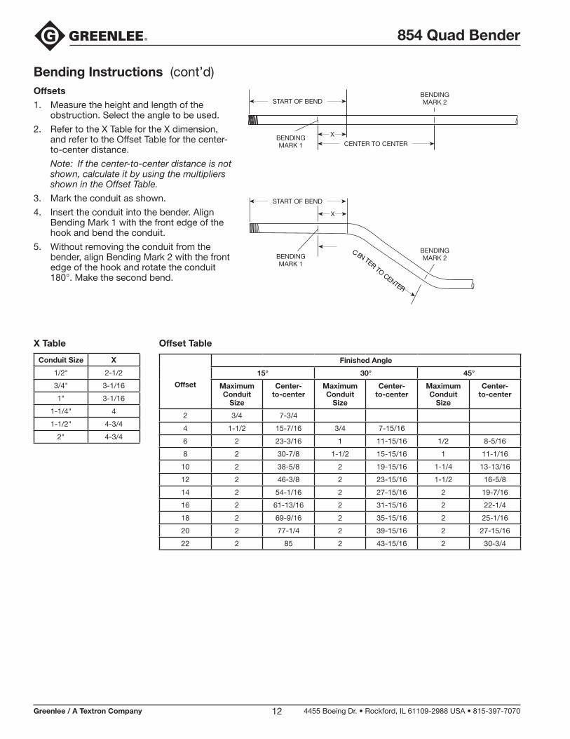
Bending Instructions (cont’d)Offsets
1. Measure the height and length of the obstruction. Select the angle to be used.
2. Refer to the X Table for the X dimension, and refer to the Offset Table for the center-to-center distance.
Note: If the center-to-center distance is not shown, calculate it by using the multipliers shown in the Offset Table.
3. Mark the conduit as shown.
4. Insert the conduit into the bender. Align Bending Mark 1 with the front edge of the hook and bend the conduit.
5. Without removing the conduit from the bender, align Bending Mark 2 with the front edge of the hook and rotate the conduit 180°. Make the second bend.
CENTERTO
CENTER
BENDINGMARK 1
BENDINGMARK 1
BENDINGMARK 2
BENDINGMARK 2
START OF BEND
START OF BEND
CENTER TO CENTERX
X
Conduit Size X
1/2" 2-1/2
3/4" 3-1/16
1" 3-1/16
1-1/4" 4
1-1/2" 4-3/4
2" 4-3/4
Offset
Finished Angle
15° 30° 45°
Maximum Conduit
Size
Center- to-center
Maximum Conduit
Size
Center- to-center
Maximum Conduit
Size
Center- to-center
2 3/4 7-3/4
4 1-1/2 15-7/16 3/4 7-15/16
6 2 23-3/16 1 11-15/16 1/2 8-5/16
8 2 30-7/8 1-1/2 15-15/16 1 11-1/16
10 2 38-5/8 2 19-15/16 1-1/4 13-13/16
12 2 46-3/8 2 23-15/16 1-1/2 16-5/8
14 2 54-1/16 2 27-15/16 2 19-7/16
16 2 61-13/16 2 31-15/16 2 22-1/4
18 2 69-9/16 2 35-15/16 2 25-1/16
20 2 77-1/4 2 39-15/16 2 27-15/16
22 2 85 2 43-15/16 2 30-3/4
X Table Offset Table
854 Quad Bender
Greenlee / A Textron Company 4455 Boeing Dr. • Rockford, IL 61109-2988 USA • 815-397-707013
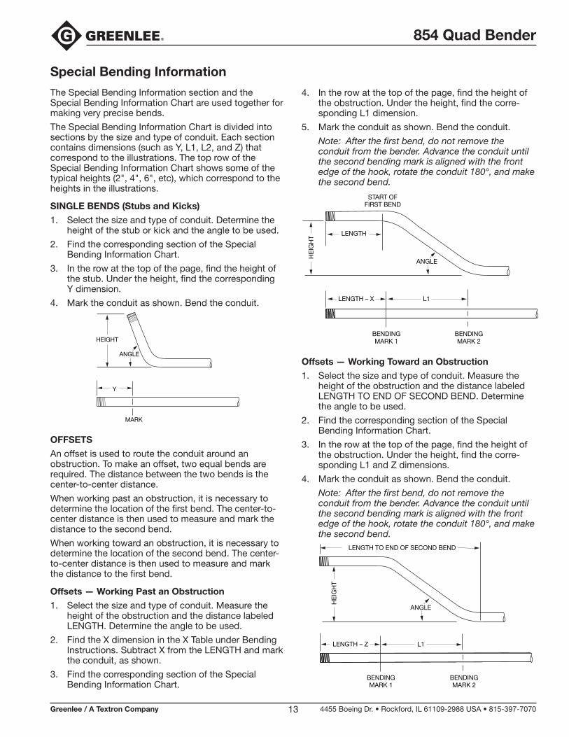
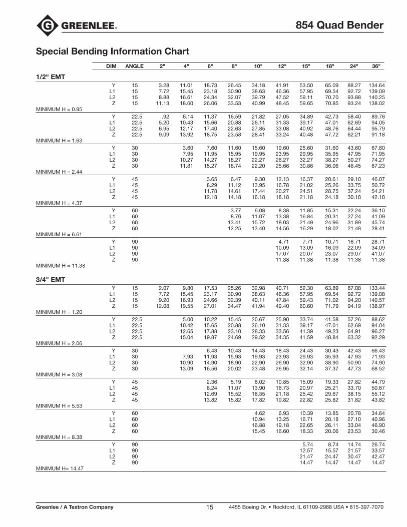
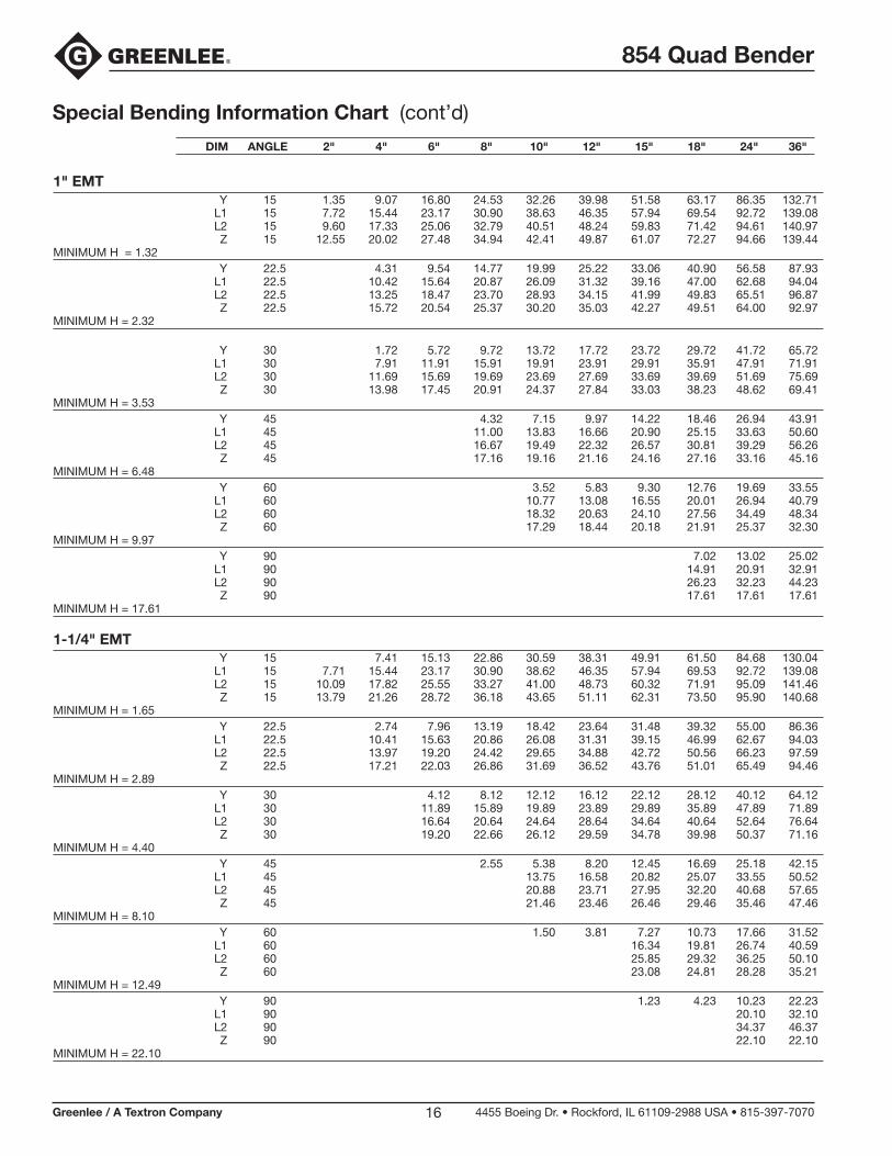
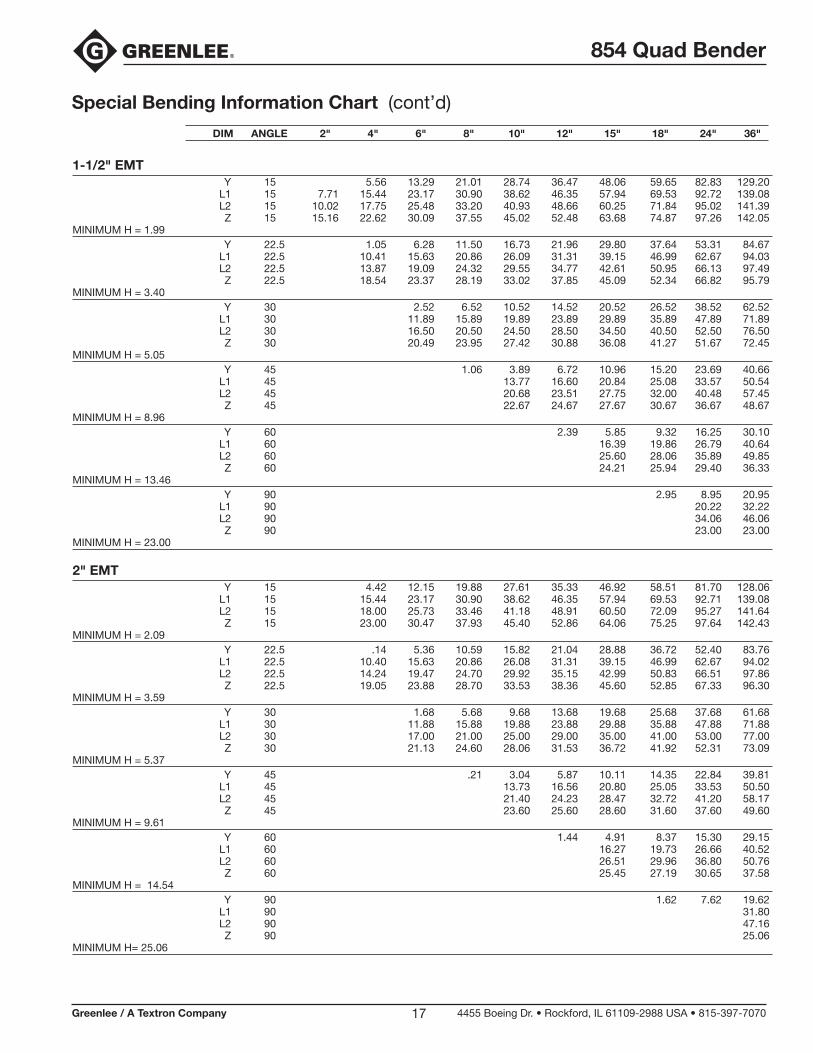
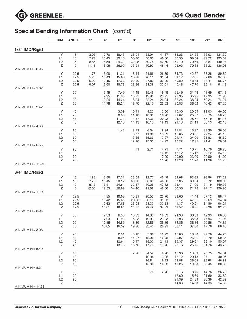
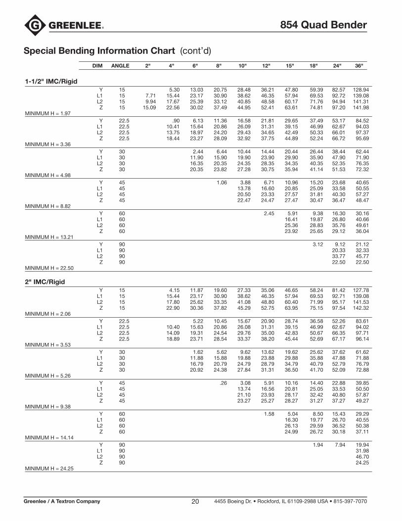
Special Bending Information
The Special Bending Information section and the Special Bending Information Chart are used together for making very precise bends.
The Special Bending Information Chart is divided into sections by the size and type of conduit. Each section contains dimensions (such as Y, L1, L2, and Z) that correspond to the illustrations. The top row of the Special Bending Information Chart shows some of the typical heights (2", 4", 6", etc), which correspond to the heights in the illustrations.
SINGLE BENDS (Stubs and Kicks)
1. Select the size and type of conduit. Determine the height of the stub or kick and the angle to be used.
2. Find the corresponding section of the Special Bending Information Chart.
3. In the row at the top of the page, find the height of the stub. Under the height, find the corresponding Y dimension.
4. Mark the conduit as shown. Bend the conduit.
Y
HEIGHT
MARK
ANGLE
OFFSETS
An offset is used to route the conduit around an obstruction. To make an offset, two equal bends are required. The distance between the two bends is the center-to-center distance.
When working past an obstruction, it is necessary to determine the location of the first bend. The center-to-center distance is then used to measure and mark the distance to the second bend.
When working toward an obstruction, it is necessary to determine the location of the second bend. The center-to-center distance is then used to measure and mark the distance to the first bend.
Offsets — Working Past an Obstruction
1. Select the size and type of conduit. Measure the height of the obstruction and the distance labeled LENGTH. Determine the angle to be used.
2. Find the X dimension in the X Table under Bending Instructions. Subtract X from the LENGTH and mark the conduit, as shown.
3. Find the corresponding section of the Special Bending Information Chart.
4. In the row at the top of the page, find the height of the obstruction. Under the height, find the corre-sponding L1 dimension.
5. Mark the conduit as shown. Bend the conduit.
Note: After the first bend, do not remove the conduit from the bender. Advance the conduit until the second bending mark is aligned with the front edge of the hook, rotate the conduit 180°, and make the second bend.
START OFFIRST BEND
LENGTH
ANGLE
HE
IGH
T
BENDINGMARK 1
BENDINGMARK 2
LENGTH – X L1
Offsets — Working Toward an Obstruction
1. Select the size and type of conduit. Measure the height of the obstruction and the distance labeled LENGTH TO END OF SECOND BEND. Determine the angle to be used.
2. Find the corresponding section of the Special Bending Information Chart.
3. In the row at the top of the page, find the height of the obstruction. Under the height, find the corre-sponding L1 and Z dimensions.
4. Mark the conduit as shown. Bend the conduit.
Note: After the first bend, do not remove the conduit from the bender. Advance the conduit until the second bending mark is aligned with the front edge of the hook, rotate the conduit 180°, and make the second bend.
BENDINGMARK 1
BENDINGMARK 2
HE
IGH
T
LENGTH TO END OF SECOND BEND
ANGLE
LENGTH – Z L1

854 Quad Bender
Greenlee / A Textron Company 4455 Boeing Dr. • Rockford, IL 61109-2988 USA • 815-397-707014
Special Bending Information (cont’d)
THREE-BEND SADDLE
A three-bend saddle is used to route the conduit around an obstruction. To make a three-bend saddle, three bends are required; the first and third bends are an equal number of degrees; the second bend is twice that number of degrees.
1. Select the size and type of conduit. Measure the height of the obstruction and the distance labeled LENGTH TO CENTER. Determine the angle to be used.
Note: The “angle to be used” is the first and third angle of the saddle (not the second), as illustrated. Refer to this angle when looking up the correspond-ing information in the Special Bending Information Chart.
2. Find the corresponding section of the Special Bending Information Chart.
3. In the row at the top of the page, find the height of the obstruction. Under the height, find the corre-sponding L1, L2 and Z dimensions.
4. Mark the conduit as shown. Bend the conduit.
Note: After the first bend, do not remove the conduit from the bender. Advance the conduit until the second bending mark is aligned with the front edge of the hook, rotate the conduit 180°, and make the second bend. Then advance the conduit to the third bending mark, rotate the conduit 180° again, and make the third bend.
BENDINGMARK 1
BENDINGMARK 3
BENDINGMARK 2
LENGTH – Z L1 L2
LENGTH TO CENTER
ANGLEHEIGHT
FOUR-BEND SADDLE
1. Select the size and type of conduit. Measure the distances labeled LENGTH, STRAIGHT SECTION, and HEIGHT. Determine the angle to be used.
2. Find the corresponding section of the Special Bending Information Chart.
3. In the row at the top of the page, find the height of the obstruction. Under the height, find the corre-sponding L1, L2 and Z dimensions.
4. Mark the conduit as shown. Bend the conduit.
BENDINGMARK 1
BENDINGMARK 3
BENDINGMARK 4
BENDINGMARK 2
LENGTH – Z L1 L1
ANGLEHEIGHT
LENGTHSTRAIGHTSECTION
L2 + STRAIGHT SECTION
U-BENDS
1. Select the size and type of conduit. Measure and mark the distances labeled HEIGHT and LENGTH.
2. Find the corresponding section of the Special Bending Information Chart.
3. In the row at the top of the page, find the height of the illustration. Under the height, find the corre-sponding L1 and Y dimensions.
4. Mark the conduit as shown. Bend the conduit.
BENDINGMARK 1
BENDINGMARK 2
Y L1
HEIGHT
LENGTH
854 Quad Bender
Greenlee / A Textron Company 4455 Boeing Dr. • Rockford, IL 61109-2988 USA • 815-397-707015
Special Bending Information Chart DIM ANGLE 2" 4" 6" 8" 10" 12" 15" 18" 24" 36"
1/2" EMT Y 15 3.28 11.01 18.73 26.45 34.18 41.91 53.50 65.09 88.27 134.64 L1 15 7.72 15.45 23.18 30.90 38.63 46.36 57.95 69.54 92.72 139.09 L2 15 8.88 16.61 24.34 32.07 39.79 47.52 59.11 70.70 93.88 140.25 Z 15 11.13 18.60 26.06 33.53 40.99 48.45 59.65 70.85 93.24 138.02MINIMUM H = 0.95 Y 22.5 .92 6.14 11.37 16.59 21.82 27.05 34.89 42.73 58.40 89.76 L1 22.5 5.20 10.43 15.66 20.88 26.11 31.33 39.17 47.01 62.69 94.05 L2 22.5 6.95 12.17 17.40 22.63 27.85 33.08 40.92 48.76 64.44 95.79 Z 22.5 9.09 13.92 18.75 23.58 28.41 33.24 40.48 47.72 62.21 91.18MINIMUM H = 1.63 Y 30 3.60 7.60 11.60 15.60 19.60 25.60 31.60 43.60 67.60 L1 30 7.95 11.95 15.95 19.95 23.95 29.95 35.95 47.95 71.95 L2 30 10.27 14.27 18.27 22.27 26.27 32.27 38.27 50.27 74.27 Z 30 11.81 15.27 18.74 22.20 25.66 30.86 36.06 46.45 67.23MINIMUM H = 2.44 Y 45 3.65 6.47 9.30 12.13 16.37 20.61 29.10 46.07 L1 45 8.29 11.12 13.95 16.78 21.02 25.26 33.75 50.72 L2 45 11.78 14.61 17.44 20.27 24.51 28.75 37.24 54.21 Z 45 12.18 14.18 16.18 18.18 21.18 24.18 30.18 42.18MINIMUM H = 4.37 Y 60 3.77 6.08 8.38 11.85 15.31 22.24 36.10 L1 60 8.76 11.07 13.38 16.84 20.31 27.24 41.09 L2 60 13.41 15.72 18.03 21.49 24.96 31.89 45.74 Z 60 12.25 13.40 14.56 16.29 18.02 21.48 28.41MINIMUM H = 6.61 Y 90 4.71 7.71 10.71 16.71 28.71 L1 90 10.09 13.09 16.09 22.09 34.09 L2 90 17.07 20.07 23.07 29.07 41.07 Z 90 11.38 11.38 11.38 11.38 11.38MINIMUM H = 11.38
3/4" EMT Y 15 2.07 9.80 17.53 25.26 32.98 40.71 52.30 63.89 87.08 133.44 L1 15 7.72 15.45 23.17 30.90 38.63 46.36 57.95 69.54 92.72 139.08 L2 15 9.20 16.93 24.66 32.39 40.11 47.84 59.43 71.02 94.20 140.57 Z 15 12.08 19.55 27.01 34.47 41.94 49.40 60.60 71.79 94.19 138.97MINIMUM H = 1.20 Y 22.5 5.00 10.22 15.45 20.67 25.90 33.74 41.58 57.26 88.62 L1 22.5 10.42 15.65 20.88 26.10 31.33 39.17 47.01 62.69 94.04 L2 22.5 12.65 17.88 23.10 28.33 33.56 41.39 49.23 64.91 96.27 Z 22.5 15.04 19.87 24.69 29.52 34.35 41.59 48.84 63.32 92.29MINIMUM H = 2.06 Y 30 6.43 10.43 14.43 18.43 24.43 30.43 42.43 66.43 L1 30 7.93 11.93 15.93 19.93 23.93 29.93 35.93 47.93 71.93 L2 30 10.90 14.90 18.90 22.90 26.90 32.90 38.90 50.90 74.90 Z 30 13.09 16.56 20.02 23.48 26.95 32.14 37.37 47.73 68.52MINIMUM H = 3.08 Y 45 2.36 5.19 8.02 10.85 15.09 19.33 27.82 44.79 L1 45 8.24 11.07 13.90 16.73 20.97 25.21 33.70 50.67 L2 45 12.69 15.52 18.35 21.18 25.42 29.67 38.15 55.12 Z 45 13.82 15.82 17.82 19.82 22.82 25.82 31.82 43.82MINIMUM H = 5.53 Y 60 4.62 6.93 10.39 13.85 20.78 34.64 L1 60 10.94 13.25 16.71 20.18 27.10 40.96 L2 60 16.88 19.18 22.65 26.11 33.04 46.90 Z 60 15.45 16.60 18.33 20.06 23.53 30.46MINIMUM H = 8.38 Y 90 5.74 8.74 14.74 26.74 L1 90 12.57 15.57 21.57 33.57 L2 90 21.47 24.47 30.47 42.47 Z 90 14.47 14.47 14.47 14.47MINIMUM H= 14.47
854 Quad Bender
Greenlee / A Textron Company 4455 Boeing Dr. • Rockford, IL 61109-2988 USA • 815-397-707016
Special Bending Information Chart (cont’d)
1" EMT Y 15 1.35 9.07 16.80 24.53 32.26 39.98 51.58 63.17 86.35 132.71 L1 15 7.72 15.44 23.17 30.90 38.63 46.35 57.94 69.54 92.72 139.08 L2 15 9.60 17.33 25.06 32.79 40.51 48.24 59.83 71.42 94.61 140.97 Z 15 12.55 20.02 27.48 34.94 42.41 49.87 61.07 72.27 94.66 139.44MINIMUM H = 1.32 Y 22.5 4.31 9.54 14.77 19.99 25.22 33.06 40.90 56.58 87.93 L1 22.5 10.42 15.64 20.87 26.09 31.32 39.16 47.00 62.68 94.04 L2 22.5 13.25 18.47 23.70 28.93 34.15 41.99 49.83 65.51 96.87 Z 22.5 15.72 20.54 25.37 30.20 35.03 42.27 49.51 64.00 92.97MINIMUM H = 2.32 Y 30 1.72 5.72 9.72 13.72 17.72 23.72 29.72 41.72 65.72 L1 30 7.91 11.91 15.91 19.91 23.91 29.91 35.91 47.91 71.91 L2 30 11.69 15.69 19.69 23.69 27.69 33.69 39.69 51.69 75.69 Z 30 13.98 17.45 20.91 24.37 27.84 33.03 38.23 48.62 69.41MINIMUM H = 3.53 Y 45 4.32 7.15 9.97 14.22 18.46 26.94 43.91 L1 45 11.00 13.83 16.66 20.90 25.15 33.63 50.60 L2 45 16.67 19.49 22.32 26.57 30.81 39.29 56.26 Z 45 17.16 19.16 21.16 24.16 27.16 33.16 45.16MINIMUM H = 6.48 Y 60 3.52 5.83 9.30 12.76 19.69 33.55 L1 60 10.77 13.08 16.55 20.01 26.94 40.79 L2 60 18.32 20.63 24.10 27.56 34.49 48.34 Z 60 17.29 18.44 20.18 21.91 25.37 32.30MINIMUM H = 9.97 Y 90 7.02 13.02 25.02 L1 90 14.91 20.91 32.91 L2 90 26.23 32.23 44.23 Z 90 17.61 17.61 17.61MINIMUM H = 17.61
1-1/4" EMT Y 15 7.41 15.13 22.86 30.59 38.31 49.91 61.50 84.68 130.04 L1 15 7.71 15.44 23.17 30.90 38.62 46.35 57.94 69.53 92.72 139.08 L2 15 10.09 17.82 25.55 33.27 41.00 48.73 60.32 71.91 95.09 141.46 Z 15 13.79 21.26 28.72 36.18 43.65 51.11 62.31 73.50 95.90 140.68MINIMUM H = 1.65 Y 22.5 2.74 7.96 13.19 18.42 23.64 31.48 39.32 55.00 86.36 L1 22.5 10.41 15.63 20.86 26.08 31.31 39.15 46.99 62.67 94.03 L2 22.5 13.97 19.20 24.42 29.65 34.88 42.72 50.56 66.23 97.59 Z 22.5 17.21 22.03 26.86 31.69 36.52 43.76 51.01 65.49 94.46MINIMUM H = 2.89 Y 30 4.12 8.12 12.12 16.12 22.12 28.12 40.12 64.12 L1 30 11.89 15.89 19.89 23.89 29.89 35.89 47.89 71.89 L2 30 16.64 20.64 24.64 28.64 34.64 40.64 52.64 76.64 Z 30 19.20 22.66 26.12 29.59 34.78 39.98 50.37 71.16MINIMUM H = 4.40 Y 45 2.55 5.38 8.20 12.45 16.69 25.18 42.15 L1 45 13.75 16.58 20.82 25.07 33.55 50.52 L2 45 20.88 23.71 27.95 32.20 40.68 57.65 Z 45 21.46 23.46 26.46 29.46 35.46 47.46MINIMUM H = 8.10 Y 60 1.50 3.81 7.27 10.73 17.66 31.52 L1 60 16.34 19.81 26.74 40.59 L2 60 25.85 29.32 36.25 50.10 Z 60 23.08 24.81 28.28 35.21MINIMUM H = 12.49 Y 90 1.23 4.23 10.23 22.23 L1 90 20.10 32.10 L2 90 34.37 46.37 Z 90 22.10 22.10MINIMUM H = 22.10
DIM ANGLE 2" 4" 6" 8" 10" 12" 15" 18" 24" 36"
854 Quad Bender
Greenlee / A Textron Company 4455 Boeing Dr. • Rockford, IL 61109-2988 USA • 815-397-707017
Special Bending Information Chart (cont’d)
1-1/2" EMT Y 15 5.56 13.29 21.01 28.74 36.47 48.06 59.65 82.83 129.20 L1 15 7.71 15.44 23.17 30.90 38.62 46.35 57.94 69.53 92.72 139.08 L2 15 10.02 17.75 25.48 33.20 40.93 48.66 60.25 71.84 95.02 141.39 Z 15 15.16 22.62 30.09 37.55 45.02 52.48 63.68 74.87 97.26 142.05MINIMUM H = 1.99 Y 22.5 1.05 6.28 11.50 16.73 21.96 29.80 37.64 53.31 84.67 L1 22.5 10.41 15.63 20.86 26.09 31.31 39.15 46.99 62.67 94.03 L2 22.5 13.87 19.09 24.32 29.55 34.77 42.61 50.95 66.13 97.49 Z 22.5 18.54 23.37 28.19 33.02 37.85 45.09 52.34 66.82 95.79MINIMUM H = 3.40 Y 30 2.52 6.52 10.52 14.52 20.52 26.52 38.52 62.52 L1 30 11.89 15.89 19.89 23.89 29.89 35.89 47.89 71.89 L2 30 16.50 20.50 24.50 28.50 34.50 40.50 52.50 76.50 Z 30 20.49 23.95 27.42 30.88 36.08 41.27 51.67 72.45MINIMUM H = 5.05 Y 45 1.06 3.89 6.72 10.96 15.20 23.69 40.66 L1 45 13.77 16.60 20.84 25.08 33.57 50.54 L2 45 20.68 23.51 27.75 32.00 40.48 57.45 Z 45 22.67 24.67 27.67 30.67 36.67 48.67MINIMUM H = 8.96 Y 60 2.39 5.85 9.32 16.25 30.10 L1 60 16.39 19.86 26.79 40.64 L2 60 25.60 28.06 35.89 49.85 Z 60 24.21 25.94 29.40 36.33MINIMUM H = 13.46 Y 90 2.95 8.95 20.95 L1 90 20.22 32.22 L2 90 34.06 46.06 Z 90 23.00 23.00MINIMUM H = 23.00
2" EMT Y 15 4.42 12.15 19.88 27.61 35.33 46.92 58.51 81.70 128.06 L1 15 15.44 23.17 30.90 38.62 46.35 57.94 69.53 92.71 139.08 L2 15 18.00 25.73 33.46 41.18 48.91 60.50 72.09 95.27 141.64 Z 15 23.00 30.47 37.93 45.40 52.86 64.06 75.25 97.64 142.43MINIMUM H = 2.09 Y 22.5 .14 5.36 10.59 15.82 21.04 28.88 36.72 52.40 83.76 L1 22.5 10.40 15.63 20.86 26.08 31.31 39.15 46.99 62.67 94.02 L2 22.5 14.24 19.47 24.70 29.92 35.15 42.99 50.83 66.51 97.86 Z 22.5 19.05 23.88 28.70 33.53 38.36 45.60 52.85 67.33 96.30MINIMUM H = 3.59 Y 30 1.68 5.68 9.68 13.68 19.68 25.68 37.68 61.68 L1 30 11.88 15.88 19.88 23.88 29.88 35.88 47.88 71.88 L2 30 17.00 21.00 25.00 29.00 35.00 41.00 53.00 77.00 Z 30 21.13 24.60 28.06 31.53 36.72 41.92 52.31 73.09MINIMUM H = 5.37 Y 45 .21 3.04 5.87 10.11 14.35 22.84 39.81 L1 45 13.73 16.56 20.80 25.05 33.53 50.50 L2 45 21.40 24.23 28.47 32.72 41.20 58.17 Z 45 23.60 25.60 28.60 31.60 37.60 49.60MINIMUM H = 9.61 Y 60 1.44 4.91 8.37 15.30 29.15 L1 60 16.27 19.73 26.66 40.52 L2 60 26.51 29.96 36.80 50.76 Z 60 25.45 27.19 30.65 37.58MINIMUM H = 14.54 Y 90 1.62 7.62 19.62 L1 90 31.80 L2 90 47.16 Z 90 25.06MINIMUM H= 25.06
DIM ANGLE 2" 4" 6" 8" 10" 12" 15" 18" 24" 36"
854 Quad Bender
Greenlee / A Textron Company 4455 Boeing Dr. • Rockford, IL 61109-2988 USA • 815-397-707018
Special Bending Information Chart (cont’d)
1/2" IMC/Rigid Y 15 3.03 10.76 18.48 26.21 33.94 41.67 53.26 64.85 88.03 134.39 L1 15 7.72 15.45 23.18 30.90 38.63 46.36 57.95 69.54 92.72 139.09 L2 15 8.87 16.59 24.32 32.05 39.78 47.50 59.10 70.69 93.87 140.23 Z 15 11.12 18.58 26.05 33.51 40.97 48.44 59.63 70.83 93.22 138.01MINIMUM H = 0.95 Y 22.5 .77 5.98 11.21 16.44 21.66 26.89 34.73 42.57 58.25 89.60 L1 22.5 5.20 10.43 15.66 20.88 26.11 31.34 39.17 47.01 62.69 94.05 L2 22.5 6.92 12.15 17.38 22.60 27.83 33.06 40.89 48.73 64.41 95.77 Z 22.5 9.07 13.90 18.73 23.56 28.38 33.21 40.46 47.70 62.18 91.15MINIMUM H = 1.62 Y 30 3.49 7.49 11.49 15.49 19.49 25.49 31.49 43.49 67.49 L1 30 7.95 11.95 15.95 19.95 23.95 29.95 35.95 47.95 71.95 L2 30 10.24 14.24 18.24 22.24 26.24 32.24 38.24 50.24 74.24 Z 30 11.78 15.24 18.70 22.17 25.63 30.83 36.02 46.42 67.20MINIMUM H = 2.42 Y 45 3.59 6.41 9.23 12.06 16.30 20.55 29.03 46.00 L1 45 8.30 11.13 13.95 16.78 21.02 25.27 33.75 50.72 L2 45 11.74 14.57 17.39 20.22 24.46 28.71 37.19 54.16 Z 45 12.13 14.13 16.13 18.13 21.13 24.13 30.13 42.13MINIMUM H = 4.33 Y 60 1.42 3.73 6.04 8.34 11.81 15.27 22.20 36.06 L1 60 8.77 11.08 13.39 16.85 20.31 27.24 41.10 L2 60 13.35 15.66 17.97 21.44 24.90 31.83 45.69 Z 60 12.18 13.33 14.49 16.22 17.95 21.41 28.34MINIMUM H = 6.55 Y 90 .71 2.71 4.71 7.71 10.71 16.70 28.70 L1 90 10.12 13.12 16.12 22.12 34.12 L2 90 17.00 20.00 23.00 29.00 41.00 Z 90 11.26 11.26 11.26 11.26 11.26MINIMUM H = 11.26
3/4" IMC/Rigid Y 15 1.86 9.58 17.31 25.04 32.77 40.49 52.08 63.68 86.86 133.22 L1 15 7.72 15.45 23.17 30.90 38.63 46.36 57.95 69.54 92.72 139.08 L2 15 9.19 16.91 24.64 32.37 40.09 47.82 59.41 71.00 94.19 140.55 Z 15 12.06 19.53 26.89 34.46 41.92 49.38 60.58 71.78 94.17 138.95MINIMUM H = 1.19 Y 22.5 4.85 10.08 15.31 20.53 25.76 33.60 41.44 57.12 88.47 L1 22.5 10.42 15.65 20.88 26.10 31.33 39.17 47.01 62.69 94.04 L2 22.5 12.62 17.85 23.08 28.30 33.53 41.37 49.21 64.89 96.24 Z 22.5 15.01 19.84 24.67 29.49 34.32 41.57 48.81 63.29 92.26MINIMUM H = 2.05 Y 30 2.33 6.33 10.33 14.33 18.33 24.33 30.33 42.33 66.33 L1 30 7.93 11.93 15.93 19.93 23.93 29.93 35.93 47.93 71.93 L2 30 10.86 14.86 18.86 22.86 26.86 32.86 38.86 50.86 74.86 Z 30 13.05 16.52 19.98 23.45 26.91 32.11 37.30 47.70 68.48MINIMUM H = 3.06 Y 45 2.31 5.13 7.96 10.79 15.03 19.28 27.76 44.73 L1 45 8.24 11.07 13.90 16.73 20.97 25.21 33.70 50.67 L2 45 12.64 15.47 18.30 21.13 25.37 29.61 38.10 55.07 Z 45 13.76 15.76 17.76 19.76 22.76 25.76 31.76 43.76MINIMUM H = 5.49 Y 60 2.28 4.59 6.90 10.36 13.83 20.75 34.61 L1 60 10.94 13.25 16.72 20.18 27.11 40.97 L2 60 16.81 19.12 22.58 26.05 32.98 46.83 Z 60 15.36 16.52 18.25 19.88 23.45 30.38MINIMUM H = 8.31 Y 90 .76 2.76 5.76 8.76 14.76 26.76 L1 90 12.60 15.60 21.60 33.60 L2 90 21.39 24.39 30.39 42.39 Z 90 14.33 14.33 14.33 14.33MINIMUM H = 14.33
DIM ANGLE 2" 4" 6" 8" 10" 12" 15" 18" 24" 36"

854 Quad Bender
Greenlee / A Textron Company 4455 Boeing Dr. • Rockford, IL 61109-2988 USA • 815-397-707019
Special Bending Information Chart (cont’d)
1" IMC/Rigid Y 15 1.08 8.81 16.52 24.25 31.97 39.70 51.29 62.88 86.07 132.43 L1 15 7.72 15.44 23.17 30.90 38.63 46.35 57.94 69.54 92.72 139.08 L2 15 9.59 17.32 25.04 32.77 40.50 48.23 59.82 71.41 94.59 140.95 Z 15 12.53 20.00 27.46 34.93 42.39 49.86 61.05 72.25 94.64 139.43MINIMUM H = 1.31 Y 22.5 4.13 9.35 14.58 19.81 25.03 32.87 40.71 56.39 87.75 L1 22.5 10.42 15.64 20.87 26.09 31.32 39.16 47.00 62.68 94.04 L2 22.5 13.22 18.45 23.68 28.90 34.13 41.97 49.81 65.49 96.84 Z 22.5 15.69 20.52 25.35 30.18 35.01 42.25 49.49 63.98 92.95 MINIMUM H = 2.31 Y 30 1.58 5.58 9.58 13.58 17.58 23.58 29.58 41.58 65.58 L1 30 7.91 11.91 15.91 19.91 23.91 29.91 35.91 47.91 71.91 L2 30 11.66 15.66 19.66 23.66 27.66 33.66 39.66 51.66 75.66 Z 30 13.95 17.41 20.88 24.34 27.81 33.00 38.20 48.59 69.38MINIMUM H = 3.51 Y 45 1.42 4.24 7.06 9.89 14.14 18.38 26.86 43.83 L1 45 11.01 13.83 16.66 20.91 25.15 33.63 50.60 L2 45 16.62 19.45 22.28 26.52 30.76 39.25 56.22 Z 45 17.11 19.11 21.11 24.11 27.11 33.11 45.11MINIMUM H = 6.44 Y 60 1.17 3.48 5.79 9.25 12.71 19.64 33.49 L1 60 10.78 13.09 16.55 20.02 26.94 40.80 L2 60 18.27 20.58 24.04 27.50 34.43 48.29 Z 60 17.22 18.37 20.11 21.84 25.30 32.23MINIMUM H = 9.91 Y 90 1.01 4.01 7.01 13.01 25.01 L1 90 14.93 20.93 32.93 L2 90 26.16 32.16 44.16 Z 90 17.49 17.49 17.49MINIMUM H = 17.49
1-1/4" IMC/Rigid Y 15 7.15 14.87 22.60 30.33 38.06 49.65 61.24 84.42 130.78 L1 15 7.71 15.44 23.17 30.90 38.62 46.35 57.94 69.53 92.72 139.08 L2 15 10.07 17.80 25.53 33.25 40.98 48.71 60.30 71.89 95.07 141.44 Z 15 13.77 21.24 28.70 36.17 43.63 51.09 62.29 73.49 95.88 140.66MINIMUM H = 1.63 Y 22.5 2.57 7.80 13.02 18.25 23.47 31.31 39.15 54.83 86.19 L1 22.5 10.41 15.63 20.86 26.09 31.31 39.15 46.99 62.67 94.03 L2 22.5 13.94 19.17 24.40 29.62 34.85 42.69 50.53 66.21 97.56 Z 22.5 17.18 22.01 26.84 31.66 36.49 43.73 50.98 65.46 94.43MINIMUM H = 2.88 Y 30 4.00 8.00 12.00 16.00 22.00 28.00 40.00 64.00 L1 30 11.89 15.89 19.89 23.89 29.89 35.89 47.89 71.89 L2 30 16.61 20.61 24.61 28.61 34.61 40.61 52.61 76.61 Z 30 19.16 22.62 26.09 29.55 34.75 39.94 50.33 71.12MINIMUM H = 4.38 Y 45 2.48 5.31 8.14 12.38 16.62 25.11 42.08 L1 45 13.75 16.58 20.83 25.07 33.55 50.52 L2 45 20.83 23.66 27.90 32.14 40.63 57.60 Z 45 21.40 23.40 26.40 29.40 35.40 47.40MINIMUM H = 8.06 Y 60 1.46 3.77 7.23 10.69 17.62 31.48 L1 60 16.35 19.82 26.74 40.60 L2 60 25.79 29.25 36.18 50.04 Z 60 23.00 24.73 28.20 35.13MINIMUM H = 12.42 Y 90 1.23 4.23 10.23 22.23 L1 90 20.13 32.13 L2 90 34.29 46.29 Z 90 21.96 21.96MINIMUM H = 21.96
DIM ANGLE 2" 4" 6" 8" 10" 12" 15" 18" 24" 36"
854 Quad Bender
Greenlee / A Textron Company 4455 Boeing Dr. • Rockford, IL 61109-2988 USA • 815-397-707020
Special Bending Information Chart (cont’d)
1-1/2" IMC/Rigid Y 15 5.30 13.03 20.75 28.48 36.21 47.80 59.39 82.57 128.94 L1 15 7.71 15.44 23.17 30.90 38.62 46.35 57.94 69.53 92.72 139.08 L2 15 9.94 17.67 25.39 33.12 40.85 48.58 60.17 71.76 94.94 141.31 Z 15 15.09 22.56 30.02 37.49 44.95 52.41 63.61 74.81 97.20 141.98MINIMUM H = 1.97 Y 22.5 .90 6.13 11.36 16.58 21.81 29.65 37.49 53.17 84.52 L1 22.5 10.41 15.64 20.86 26.09 31.31 39.15 46.99 62.67 94.03 L2 22.5 13.75 18.97 24.20 29.43 34.65 42.49 50.33 66.01 97.37 Z 22.5 18.44 23.27 28.09 32.92 37.75 44.89 52.24 66.72 95.69MINIMUM H = 3.36 Y 30 2.44 6.44 10.44 14.44 20.44 26.44 38.44 62.44 L1 30 11.90 15.90 19.90 23.90 29.90 35.90 47.90 71.90 L2 30 16.35 20.35 24.35 28.35 34.35 40.35 52.35 76.35 Z 30 20.35 23.82 27.28 30.75 35.94 41.14 51.53 72.32MINIMUM H = 4.98 Y 45 1.06 3.88 6.71 10.96 15.20 23.68 40.65 L1 45 13.78 16.60 20.85 25.09 33.58 50.55 L2 45 20.50 23.33 27.57 31.81 40.30 57.27 Z 45 22.47 24.47 27.47 30.47 36.47 48.47MINIMUM H = 8.82 Y 60 2.45 5.91 9.38 16.30 30.16 L1 60 16.41 19.87 26.80 40.66 L2 60 25.36 28.83 35.76 49.61 Z 60 23.92 25.65 29.12 36.04MINIMUM H = 13.21 Y 90 3.12 9.12 21.12 L1 90 20.33 32.33 L2 90 33.77 45.77 Z 90 22.50 22.50MINIMUM H = 22.50
2" IMC/Rigid Y 15 4.15 11.87 19.60 27.33 35.06 46.65 58.24 81.42 127.78 L1 15 15.44 23.17 30.90 38.62 46.35 57.94 69.53 92.71 139.08 L2 15 17.80 25.62 33.35 41.08 48.80 60.40 71.99 95.17 141.53 Z 15 22.90 30.36 37.82 45.29 52.75 63.95 75.15 97.54 142.32MINIMUM H = 2.06 Y 22.5 5.22 10.45 15.67 20.90 28.74 36.58 52.26 83.61 L1 22.5 10.40 15.63 20.86 26.08 31.31 39.15 46.99 62.67 94.02 L2 22.5 14.09 19.31 24.54 29.76 35.00 42.83 50.67 66.35 97.71 Z 22.5 18.89 23.71 28.54 33.37 38.20 45.44 52.69 67.17 96.14MINIMUM H = 3.53 Y 30 1.62 5.62 9.62 13.62 19.62 25.62 37.62 61.62 L1 30 11.88 15.88 19.88 23.88 29.88 35.88 47.88 71.88 L2 30 16.79 20.79 24.79 28.79 34.79 40.79 52.79 76.79 Z 30 20.92 24.38 27.84 31.31 36.50 41.70 52.09 72.88 MINIMUM H = 5.26 Y 45 .26 3.08 5.91 10.16 14.40 22.88 39.85 L1 45 13.74 16.56 20.81 25.05 33.53 50.50 L2 45 21.10 23.93 28.17 32.42 40.80 57.87 Z 45 23.27 25.27 28.27 31.27 37.27 49.27MINIMUM H = 9.38 Y 60 1.58 5.04 8.50 15.43 29.29 L1 60 16.30 19.77 26.70 40.55 L2 60 26.13 29.59 36.52 50.38 Z 60 24.99 26.72 30.18 37.11MINIMUM H = 14.14 Y 90 1.94 7.94 19.94 L1 90 31.98 L2 90 46.70 Z 90 24.25MINIMUM H = 24.25
DIM ANGLE 2" 4" 6" 8" 10" 12" 15" 18" 24" 36"
854 Quad Bender
Greenlee / A Textron Company 4455 Boeing Dr. • Rockford, IL 61109-2988 USA • 815-397-707021
Maintenance
Electric shock hazard:
Disconnect the unit from power before servicing.
Failure to observe this warning could result in severe injury or death.
Wear eye protection when operating or servicing this tool.
Failure to wear eye protection could result in serious eye injury from flying debris.
Schedule
Component Maintenance Activity Maintenance Interval
Chain Lubrication and Tension Adjustment
Every 6 months*
Roller Supports Cleaning and Lubrication
Every 6 months*
Commutator Brushes Replacement
When drive unit performance
diminishes noticeably
* More often if the bender is used in dusty or corrosive environments
Chain Lubrication and Tension Adjustment
1. Disconnect the bender from the power source.
2. See the 1-1/2" to 2" Side Exploded View. Remove the 1-1/2" to 2" shoe (see Changing Shoes in this section of the manual).
3. See the Main Exploded View. Remove the screws (23) and front chain guard assembly (4).
4. Spray a motorcycle chain lubricant on the inside of the chain between the sprockets while pressing UNLOAD. Lubricate the entire length of the chain.
5. Check the amount of slack halfway between the sprockets. If the chain slack is :
More than 25 mm (1"), proceed to step 6.
Less than 25 mm (1"), proceed to step 10.
6. Remove 11 screws (23) and motor guard (5).
7. Loosen the two motor mounting screws (25) on the front, and the two on the back, and the nut (22).
8. Torque the eccentric locator (21) to 81 Nm (60 ft-lb). Maintain this amount of torque while tightening the nut (22) and two front screws (25).
9. Tighten the two rear screws (25).
10. Assemble in reverse order.
1/2" to 1-1/4" Roller Support
1. Disconnect the bender from the power source.
2. Remove support pivot pin (19). Remove roller support (7).
3. Spray a motorcycle chain lubricant through the 3 mm (1/8") diameter hole in each roller. Rotate each roller to distribute the lubricant.
4. Spray the pivot pin.
5. Wipe away any excess lubricant.
6. Replace the roller support and pivot pin.
•
•
854 Quad Bender
Greenlee / A Textron Company 4455 Boeing Dr. • Rockford, IL 61109-2988 USA • 815-397-707022
Maintenance (cont’d)1-1/2" to 2" Roller Support
1. Disconnect the bender from the power source.
2. Remove the 1-1/2" to 2" shoe (see Changing Shoes in this section of the manual).
3. See the 1-1/2" to 2" Roller Support Unit Exploded View. Use a pair of needlenose pliers to disconnect the springs (104) from the holes in the side of the bender frame beneath the roller support unit.
4. See the Main Exploded View. Remove the squeeze adjustment arm screw (97) and arm (74).
5. Remove the three button head cap screws (96) and adapter sleeve (92).
6. Place one hand under the support arms (71) to support the weight of the roller support unit. Remove the eccentric shaft (91).
Note: You may need to rotate the eccentric shaft to remove it.
Pinch points:
Use both hands to hold the two lead and two tail rollers to prevent the rollers from pivoting.
Failure to observe this precaution could result in injury or property damage.
7. Lift the roller support subassembly to the left and upward.
8. On the 1-1/2" roller group:
Loosen the sleeve set screw (98) and remove the 1-1/2" pivot roller shaft (86) with grip (90). Remove the sleeve (87).
Remove two hex head screws (93). Remove the outer roller plate (75).
Remove the tail roller (84).
Remove all components of the split roller assembly.
9. On the 2" roller group:
Loosen the sleeve set screw (98) and press out the 2" pivot shaft (88). Remove the sleeve (89).
Remove the hex head screw (93). Remove one retaining ring (95) from the tail roller shaft (83). Remove outer roller plate (76).
Remove the tail roller (82) and center roller (85).
Remove all components of the split roller assembly.
•
•
•
•
•
•
•
•
10. Clean off all of the grease and dirt.
11. Inspect each item. Replace any worn, damaged, or missing items.
12. Lubricate all working surfaces with a high-quality grease.
13. Replace all components in reverse order, noting the following:
On both roller groups: To ease the assembly of the split roller subassemblies, begin by slipping the O-rings onto the side plates. Assemble the split roller subassemblies as shown, then slip the O-rings into their correct positions.
On the 2" roller group only: After replacing any split roller components, add or remove shim washers (99, 119, or 150) as needed.
On the 1-1/2" roller group: Install the two bel-leville washers (100) so that the inside diameters contact each other.
Use Loctite® 271 on the two hex head screws (93). Torque to 55 to 61 Nm (40 to 45 ft-lb).
14. Position the roller support arms (71) as shown. Assemble the roller groups to the support arms.
15. Reinstall the roller support unit to the bender. Keep one hand under the support arms so they do not drop completely below the set screw (107).
16. Insert the eccentric shaft (91).
Note: You may need to rotate the eccentric shaft to get it to seat completely.
17. Install the adapter sleeve (92) and three button head cap screws (96).
18. Install the adjustment arm (74) and adjustment arm screw (97).
19. Attach the springs (104) to the holes in the side of the bender frame beneath the roller support unit.
20. Put the bender in the horizontal bending position. Adjust the set screw (107), if necessary, so that the support arms (71) are centered between the front and back plates. Engage and disengage the roller support unit to be sure that it moves freely.
•
•
•
•
854 Quad Bender
Greenlee / A Textron Company 4455 Boeing Dr. • Rockford, IL 61109-2988 USA • 815-397-707023
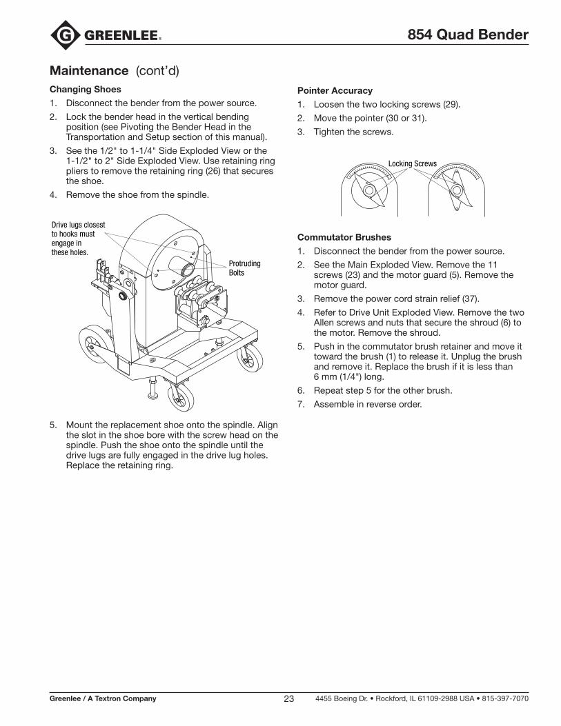
Maintenance (cont’d)Changing Shoes
1. Disconnect the bender from the power source.
2. Lock the bender head in the vertical bending position (see Pivoting the Bender Head in the Transportation and Setup section of this manual).
3. See the 1/2" to 1-1/4" Side Exploded View or the 1-1/2" to 2" Side Exploded View. Use retaining ring pliers to remove the retaining ring (26) that secures the shoe.
4. Remove the shoe from the spindle.
Drive lugs closest to hooks must engage in these holes.
ProtrudingBolts
5. Mount the replacement shoe onto the spindle. Align the slot in the shoe bore with the screw head on the spindle. Push the shoe onto the spindle until the drive lugs are fully engaged in the drive lug holes. Replace the retaining ring.
Pointer Accuracy
1. Loosen the two locking screws (29).
2. Move the pointer (30 or 31).
3. Tighten the screws.
Locking Screws
Commutator Brushes
1. Disconnect the bender from the power source.
2. See the Main Exploded View. Remove the 11 screws (23) and the motor guard (5). Remove the motor guard.
3. Remove the power cord strain relief (37).
4. Refer to Drive Unit Exploded View. Remove the two Allen screws and nuts that secure the shroud (6) to the motor. Remove the shroud.
5. Push in the commutator brush retainer and move it toward the brush (1) to release it. Unplug the brush and remove it. Replace the brush if it is less than 6 mm (1/4") long.
6. Repeat step 5 for the other brush.
7. Assemble in reverse order.
854 Quad Bender
Greenlee / A Textron Company 4455 Boeing Dr. • Rockford, IL 61109-2988 USA • 815-397-707024
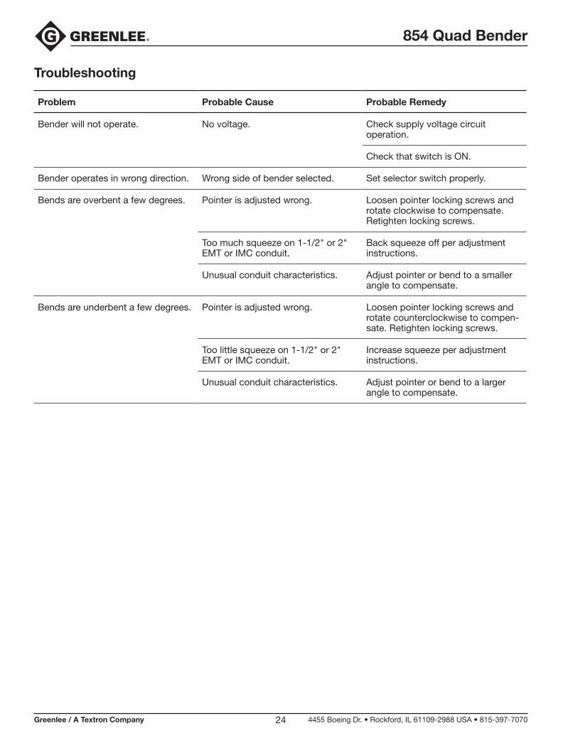
Troubleshooting
Problem Probable Cause Probable Remedy
Bender will not operate. No voltage. Check supply voltage circuit operation.
Check that switch is ON.
Bender operates in wrong direction. Wrong side of bender selected. Set selector switch properly.
Bends are overbent a few degrees. Pointer is adjusted wrong. Loosen pointer locking screws and rotate clockwise to compensate. Retighten locking screws.
Too much squeeze on 1-1/2" or 2" EMT or IMC conduit.
Back squeeze off per adjustment instructions.
Unusual conduit characteristics. Adjust pointer or bend to a smaller angle to compensate.
Bends are underbent a few degrees. Pointer is adjusted wrong. Loosen pointer locking screws and rotate counterclockwise to compen-sate. Retighten locking screws.
Too little squeeze on 1-1/2" or 2" EMT or IMC conduit.
Increase squeeze per adjustment instructions.
Unusual conduit characteristics. Adjust pointer or bend to a larger angle to compensate.

854 Quad Bender
Greenlee / A Textron Company 4455 Boeing Dr. • Rockford, IL 61109-2988 USA • 815-397-707025
Troubleshooting (cont’d)
The following flow charts show the suggested trouble-shooting procedures for some bender problems. They by no means encompass all possible problems or solutions.
Electric shock hazard:
Contact with live circuits can result in severe injury or death.
Some troubleshooting steps require power to the bender. This type of troubleshooting step should only be performed at authorized Greenlee service centers by personnel who are familiar with safe troubleshooting procedures.
Failure to observe these warnings could result in severe injury or death.
•
•
YES
YES
NO
YES
YES
YES
Won’t bend
YES
YES
NO
YES
NO
NO
NO
NO
YES
Trips circuit breaker
Won’t stop
Bender only runs in one direction
YES
NOIs 115 VAC measured at PGU board input?
Plugged into dead cir-cuit, bad power cord, or switch is bad or off.
NO Replace transformer unit.Does the green LED on the I/O board light?
YES Replace PGU.Are metal oxide varistors (MOVs) on PGU board damaged or discolored?
NODoes the green LED on the PGU light? Replace PGU.
NO Unplug pendant or I/O and check switch for continuity. If ok, replace I/O.
Does amber or red LED on I/O light when BEND or UNLOAD is pressed?
NODoes relay on I/O operate when BEND or UNLOAD is pressed?
Replace I/O.
Replace PGU.
YESOn 854 move pendant plug to I/O board. Does bender run bothdirections?
Replace direction switch assembly.
NO Check and replace pendant switch.
Does amber or red LED light when switch is pressed?
NOReplace PGU.
When amber or red LED is on, is 12 VDC measured at large relay coil on PGU (where relay wire unit connects)?
Replace 918 6645.6 relay.
YESUse 115 VAC.Is the supply line voltage low?
YES Replace pendant switch.
Does bender stop when the pendant is unplugged?
Replace PGU.
Are the proper support rollers and shoe groove being used for the type and size of conduit be-ing bent?
NO Follow directions in instruction manual.
Is the current on the 115 VAC line exceeding 20 amps?
NO Replace circuit breaker.
Is the DC current to the motor exceeding 17 amps?
YES Replace motor.
When BEND is pressed, is the voltage sent to the motor 20 to 50 volts over the AC line voltage?
NO Replace bridge rectifier (918 5997.2).
Are connectors corroded?YES
Clean.
Replace PGU.
854 Quad Bender
Greenlee / A Textron Company 4455 Boeing Dr. • Rockford, IL 61109-2988 USA • 815-397-707026
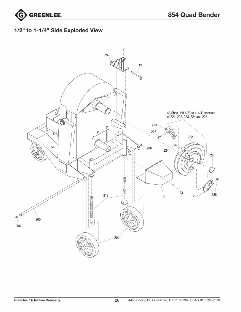
1/2" to 1-1/4" Side Exploded View
24
7
19
204
205
206
206
213 5
26
23
43 Shoe Unit 1/2" to 1-1/4" consistsof 221, 222, 223, 224 and 225
223
225
224
222
225221

854 Quad Bender
Greenlee / A Textron Company 4455 Boeing Dr. • Rockford, IL 61109-2988 USA • 815-397-707027
1-1/2" to 2" Side Exploded View
3
207
215
207
215
213
74 96
91
92
26
224
226
226
227
228
229
44 Shoe Unit 1-1/2" to 2" consistsof 224, 226, 227, 228 and 229
232
The Roller Support Unitexploded view is onthe following page.
97
854 Quad Bender
Greenlee / A Textron Company 4455 Boeing Dr. • Rockford, IL 61109-2988 USA • 815-397-707028
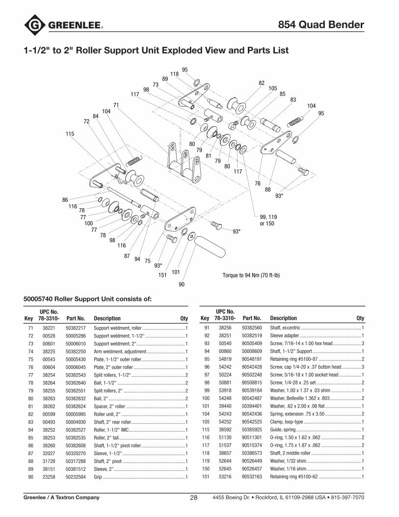
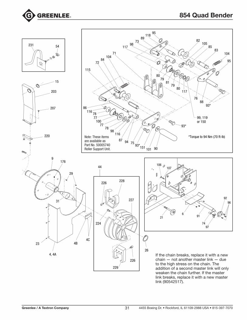
1-1/2" to 2" Roller Support Unit Exploded View and Parts List
71 38221 50382217 Supportweldment,roller..................................1
72 00528 50005286 Supportweldment,1-1/2"................................1
73 00601 50006010 Supportweldment,2".......................................1
74 38225 50382250 Armweldment,adjustment...............................1
75 00543 50005430 Plate,1-1/2"outerroller...................................1
76 00604 50006045 Plate,2"outerroller.........................................1
77 38254 50382543 Splitrollers,1-1/2"...........................................2
78 38264 50382640 Ball,1-1/2"......................................................2
79 38255 50382551 Splitrollers,2".................................................2
80 38263 50382632 Ball,2".............................................................2
81 38262 50382624 Spacer,2"roller...............................................1
82 00599 50005995 Rollerunit,2"...................................................1
83 00493 50004930 Shaft,2"rearroller...........................................1
84 38252 50382527 Roller,1-1/2"IMC.............................................1
85 38253 50382535 Roller,2"tail.....................................................1
86 38260 50382608 Shaft,1-1/2"pivotroller...................................1
87 32027 50320270 Sleeve,1-1/2"..................................................1
88 31728 50317288 Shaft,2"pivot..................................................1
89 38151 50381512 Sleeve,2".........................................................1
90 23258 50232584 Grip..................................................................1
UPCNo.Key 78-3310- PartNo. Description Qty
91 38256 50382560 Shaft,eccentric................................................1
92 38251 50382519 Sleeveadapter.................................................1
93 50540 90505409 Screw,7/16-14x1.00hexhead.......................3
94 00860 50008609 Shaft,1-1/2"Support.......................................1
95 54819 90548191 Retainingring#5100-87..................................2
96 54242 90542428 Screw,cap1/4-20x.37buttonhead................3
97 50224 90502248 Screw,5/16-18x1.00sockethead..................1
98 50881 90508815 Screw,1/4-28x.25set....................................2
99 53918 90539184 Washer,1.00x1.37x.03shim........................1
100 54248 90542487 Washer,Belleville1.362x.803.........................2
101 39440 50394401 Washer,.62x2.00x.06flat.............................1
104 54243 90542436 Spring,extension.75x3.50.............................2
105 54252 90542525 Clamp,loop-type..............................................1
115 38592 50385925 Guide,spring....................................................1
116 51130 90511301 O-ring,1.50x1.62x.062................................2
117 51537 90515374 O-ring,1.75x1.87x.062................................2
118 38657 50386573 Shaft,2middleroller........................................1
119 52644 90526449 Washer,1/32shim............................................1
150 52645 90526457 Washer,1/16shim............................................1
151 53216 90532163 Retainingring#5100-62..................................1
95118
8973
98117
71104
8472
115
86116
7877
10077
7898
116
87 94 7593*
151 101
90
93*
99, 119or 150
Torque to 94 Nm (70 ft-lb)
93*88
76
117
95104
8385
10582
8079
8179
80
50005740 Roller Support Unit consists of:
UPCNo.Key 78-3310- PartNo. Description Qty
854 Quad Bender
Greenlee / A Textron Company 4455 Boeing Dr. • Rockford, IL 61109-2988 USA • 815-397-707029
22
23
10
253
4
24 6
5
2
1
20
21
16
15
13
14
17
1918
12
8
1
2
9
23
8
11
8A
22
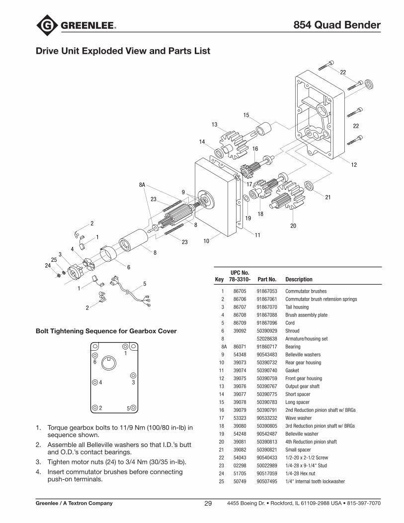
Drive Unit Exploded View and Parts List
1. Torque gearbox bolts to 11/9 Nm (100/80 in-lb) in sequence shown.
2. Assemble all Belleville washers so that I.D.’s butt and O.D.’s contact bearings.
3. Tighten motor nuts (24) to 3/4 Nm (30/35 in-lb).
4. Insert commutator brushes before connecting push-on terminals.
Bolt Tightening Sequence for Gearbox Cover
6
4 3
1
2 5
UPCNo.Key 78-3310- PartNo. Description
1 86705 91867053 Commutatorbrushes
2 86706 91867061 Commutatorbrushretensionsprings
3 86707 91867070 Tailhousing
4 86708 91867088 Brushassemblyplate
5 86709 91867096 Cord
6 39092 50390929 Shroud
8 52028638 Armature/housingset
8A 86071 91860717 Bearing
9 54348 90543483 Bellevillewashers
10 39073 50390732 Reargearhousing
11 39074 50390740 Gasket
12 39075 50390759 Frontgearhousing
13 39076 50390767 Outputgearshaft
14 39077 50390775 Shortspacer
15 39078 50390783 Longspacer
16 39079 50390791 2ndReductionpinionshaftw/BRGs
17 53323 90533232 Wavewasher
18 39080 50390805 3rdReductionpinionshaftw/BRGs
19 54248 90542487 Bellevillewasher
20 39081 50390813 4thReductionpinionshaft
21 39082 50390821 Smallspacer
22 54043 90540433 1/2-20x2-1/2Screw
23 02298 50022989 1/4-28x9-1/4"Stud
24 51705 90517059 1/4-28Hexnut
25 50749 90507495 1/4"Internaltoothlockwasher
854 Quad Bender
Greenlee / A Textron Company 4455 Boeing Dr. • Rockford, IL 61109-2988 USA • 815-397-707030
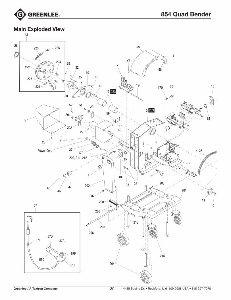
Main Exploded View
3
58
58
4, 4A
5
7
19
205
206
206
213
204
215
13
17
12
11
1610
27
23
2932
26
9176
29
31
8
201
6
2024746
45
207
207
203
1518
1815
2
15
15
2533
21
209, 211, 212
51
50
225223
222
225
221
224
224
228226
227
226
229
4C4B
2220A
14, 28
220
220
60
170 36
59
2052
208
43
44
57
57E57D
57A
57F
57B
57C
23
23
54231
Power Cord 37170
30233
233
26
854 Quad Bender
Greenlee / A Textron Company 4455 Boeing Dr. • Rockford, IL 61109-2988 USA • 815-397-707031
3
58
58
4, 4A
5
7
19
205
206
206
213
204
215
13
17
12
11
1610
27
23
2932
26
9176
29
31
8
201
6
2024746
45
207
207
203
1518
1815
2
15
15
2533
21
209, 211, 212
51
50
225223
222
225
221
224
224
228226
227
226
229
4C4B
2220A
14, 28
220
220
60
170 36
59
2052
208
43
44
57
57E57D
57A
57F
57B
57C
23
23
54231
Power Cord 37170
30233
233
2695
11889
7398
117
71104
8472
115
86116
7877
10077
7898
116
87 94 7593*
151 101 90
93*
99, 119or 150
*Torque to 94 Nm (70 ft-lb)
93*88
76
117
95
10483
85105
82
8079
8179
80
Note: These items are available asPart No. 50005740Roller Support Unit.
106107
9692
9121
7497
6
If the chain breaks, replace it with a new chain — not another master link — due to the high stress on the chain. The addition of a second master link will only weaken the chain further. If the master link breaks, replace it with a new master link (90542517).

854 Quad Bender
Greenlee / A Textron Company 4455 Boeing Dr. • Rockford, IL 61109-2988 USA • 815-397-707032
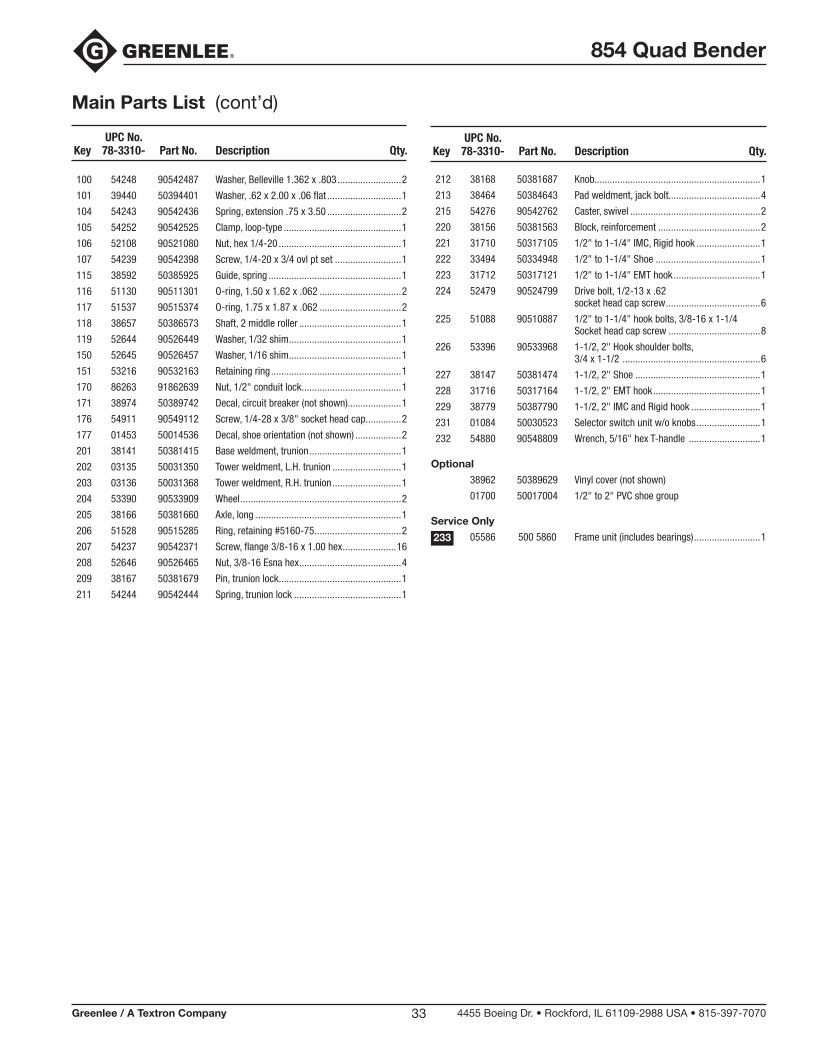
UPCNo.Key 78-3310- PartNo. Description Qty.
UPCNo.Key 78-3310- PartNo. Description Qty.
Main Parts List
2 01622 50016229 Frameweldment..............................................1
3 38217 50382179 Guardweldment,topchain...............................1
4 38983 50389831 Guardassembly,frontchain.............................1
4A 38236 50382365 Guard,front......................................................1
4B 38244 50382446 Retainer...........................................................1
4C 50160 90501608 Rivet,3/16"pop...............................................2
5 38232 50382322 Guardweldment,motor....................................1
6 01607 50016075 Guard,bottom..................................................1
7 38199 50381997 Supportweldment,1/2"to1-1/4"RLR.............1
8 38250 50382500 Driveunit..........................................................1
9 01702 50017020 Spindleweldment,main...................................1
10 38193 50381938 Plateweldment,drive.......................................1
11 54253 90542533 Sprocket,#6014T............................................1
12 38267 50382675 Key,drivesprocket...........................................1
13 54255 90542550 Bearing,sleeve#48DU40.................................2
14 54250 90542509 Chain,#6092P.................................................1
15 54462 90544625 Ring,retainingTruarc#5100-200.....................4
16 38265 50382659 Washer,mainspindle........................................2
17 38268 50382683 Key,shoedrive.................................................1
18 38457 50384570 Plate,hoist.......................................................2
19 55204 90552040 Pin,1/2"to1-1/4"supportpivot.......................1
20 38257 50382578 Spacer,motormount........................................1
20A 39488 50394886 Spacer,thinmotormount.................................1
21 38228 50382284 Locatoreeldment,rccentric..............................1
22 54265 90542568 Nut,1/2-13lock...............................................1
23 51655 90516559 Screw,#10-16x.50hexhead........................31
25 53903 90539036 Screw,cap1/2-13x1.00.................................4
26 52501 90525019 Ring,retainingTruarc#5100-287.....................2
27 54345 90543459 Screw,set1/2-20x.75socket.........................1
28 54251 90542517 Link,connecting#60chain...............................1
29 52871 90528719 Screw,1/4-20x.75socket...............................4
30 03095 50030957 Pointer,1/2"to1-1/4"......................................1
31 03099 50030990 Pointer,1-1/2"to2".........................................1
32 03104 50031040 Spacer,pointer.................................................2
33 52597 90525973 Washer,flat.56x1.37x.109...........................4
36 86767 91867673 Strainrelief,pendant.......................................1
37 54124 90541243 Strainrelief.......................................................1
43 38780 50387804 Shoeunit,1/2"to1-1/4"..................................1
44 38148 50381482 Shoeunit,1-1/2"to2".....................................1
45 52203 90522036 Screw,machine#6-32x.25.............................2
46 29708 50297082 Guard,breakerswitch......................................1
47 86385 91863856 Breaker,circuit20amp....................................1
50 54927 90549279 Screw,cap#8-32x1.37socket.......................4
51 86841 91868416 Brake,motor....................................................1
52 38807 50388070 Key,brake........................................................1
54 54151 90541510 Knob,plasticw/setscrew................................1
57 39839 50398393 Switch,pendant...............................................1
57A 86449 91864496 Switch,centeroff.............................................1
57B 31902 50319027 Handle,righthalf..............................................1
57C 53441 90534417 Screw,#6-20x.625panhead,self-tapping.....3
57D 31901 50319019 Handle,lefthalf................................................1
57E 39837 50398377 Cord.................................................................1
57F 35487 50354876 Decal,faceplate...............................................1
58 03129 50031295 Decal,angle.....................................................2
59 51751 90517512 Screw,drive.....................................................4
60 03101 50031015 Nameplate........................................................1
61 38892 50388924 Decal,warning(notshown)..............................1
62 38893 50388932 Decal,liftingeye(notshown)............................1
65 03105 50031058 Decal,selectswitchsize(notshown)................1
67 38898 50388983 Decal,benderpivotlock(notshown)................1
68 38899 50388991 Decal,rolleradjustment(notshown).................1
69 02263 50022636 Decal,rollerengagement(notshown)...............1
70 03100 50031007 Decal,operation(notshown)............................3
71 38221 50382217 Supportweldment,roller..................................1
72 00528 50005286 Supportweldment,1-1/2"................................1
73 00601 50006010 Supportweldment,2".......................................1
74 38225 50382250 Armweldment,adjustment...............................1
75 00543 50005430 Plate,1-1/2"outerroller...................................1
76 00604 50006045 Plate,2"outerroller.........................................1
77 38254 50382543 Rol,1-1/2".......................................................2
78 38264 50382640 Ball,1-1/2"......................................................2
79 38255 50382551 Rol,2"..............................................................2
80 38263 50382632 Ball,2".............................................................2
81 38262 50382624 Spacer,2"roller...............................................1
82 00599 50005995 Rollerunit,2"...................................................1
83 00493 50004930 Shaft,2"rearroller...........................................1
84 38252 50382527 Roller,1-1/2"IMC.............................................1
85 38253 50382535 Roller,2"tail.....................................................2
86 38260 50382608 Shaft,1-1/2"pivotroller...................................1
87 32027 50320270 Sleeve,1-1/2"..................................................1
88 31728 50317288 Shaft,2"pivot..................................................1
89 38151 50381512 Sleeve,2".........................................................1
90 23258 50232584 Grip..................................................................1
91 38256 50382560 Shaft,eccentric................................................1
92 38251 50382519 Sleeve,adapter.................................................1
93 50540 90505409 Screw,7/16-14x1.00hexhead.......................3
94 00860 50008609 Shaft,1-1/2"support.......................................1
95 54819 90548191 Retainingring#5100-100................................2
96 54242 90542428 Screw,cap1/4-20x.37buttonhead................3
97 50224 90502248 Screw,5/16-18x1.00sockethead..................1
98 50881 90508815 Screw,1/4-28x.25set....................................2
99 53018 90539184 Washer,1.00x1.37x.03shim........................1
854 Quad Bender
Greenlee / A Textron Company 4455 Boeing Dr. • Rockford, IL 61109-2988 USA • 815-397-707033
UPCNo.Key 78-3310- PartNo. Description Qty.
Main Parts List (cont’d)
100 54248 90542487 Washer,Belleville1.362x.803.........................2
101 39440 50394401 Washer,.62x2.00x.06flat.............................1
104 54243 90542436 Spring,extension.75x3.50.............................2
105 54252 90542525 Clamp,loop-type..............................................1
106 52108 90521080 Nut,hex1/4-20................................................1
107 54239 90542398 Screw,1/4-20x3/4ovlptset..........................1
115 38592 50385925 Guide,spring....................................................1
116 51130 90511301 O-ring,1.50x1.62x.062................................2
117 51537 90515374 O-ring,1.75x1.87x.062................................2
118 38657 50386573 Shaft,2middleroller........................................1
119 52644 90526449 Washer,1/32shim............................................1
150 52645 90526457 Washer,1/16shim............................................1
151 53216 90532163 Retainingring...................................................1
170 86263 91862639 Nut,1/2"conduitlock.......................................1
171 38974 50389742 Decal,circuitbreaker(notshown).....................1
176 54911 90549112 Screw,1/4-28x3/8"socketheadcap..............2
177 01453 50014536 Decal,shoeorientation(notshown)..................2
201 38141 50381415 Baseweldment,trunion....................................1
202 03135 50031350 Towerweldment,L.H.trunion...........................1
203 03136 50031368 Towerweldment,R.H.trunion...........................1
204 53390 90533909 Wheel...............................................................2
205 38166 50381660 Axle,long.........................................................1
206 51528 90515285 Ring,retaining#5160-75..................................2
207 54237 90542371 Screw,flange3/8-16x1.00hex.....................16
208 52646 90526465 Nut,3/8-16Esnahex........................................4
209 38167 50381679 Pin,trunionlock................................................1
211 54244 90542444 Spring,trunionlock..........................................1
UPCNo.Key 78-3310- PartNo. Description Qty.
212 38168 50381687 Knob.................................................................1
213 38464 50384643 Padweldment,jackbolt....................................4
215 54276 90542762 Caster,swivel...................................................2
220 38156 50381563 Block,reinforcement........................................2
221 31710 50317105 1/2"to1-1/4"IMC,Rigidhook.........................1
222 33494 50334948 1/2"to1-1/4"Shoe.........................................1
223 31712 50317121 1/2"to1-1/4"EMThook..................................1
224 52479 90524799 Drivebolt,1/2-13x.62 socketheadcapscrew.....................................6
225 51088 90510887 1/2"to1-1/4"hookbolts,3/8-16x1-1/4 Socketheadcapscrew....................................8
226 53396 90533968 1-1/2,2"Hookshoulderbolts, 3/4x1-1/2......................................................6
227 38147 50381474 1-1/2,2"Shoe.................................................1
228 31716 50317164 1-1/2,2"EMThook..........................................1
229 38779 50387790 1-1/2,2"IMCandRigidhook...........................1
231 01084 50030523 Selectorswitchunitw/oknobs.........................1
232 54880 90548809 Wrench,5/16"hexT-handle............................1
Optional
38962 50389629 Vinylcover(notshown)
01700 50017004 1/2"to2"PVCshoegroup
Service Only
05586 5005860 Frameunit(includesbearings)..........................1233
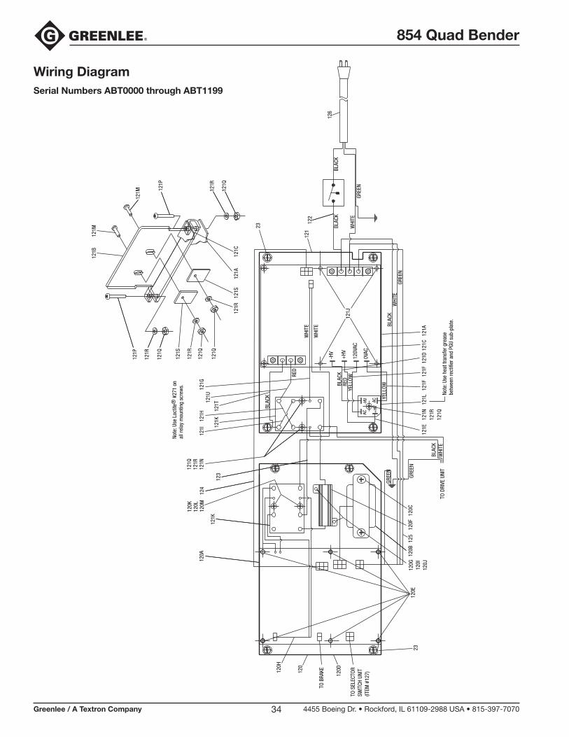
854 Quad Bender
Greenlee / A Textron Company 4455 Boeing Dr. • Rockford, IL 61109-2988 USA • 815-397-707034
Wiring DiagramSerial Numbers ABT0000 through ABT1199
121K
121U
120K
120L
120M
120G
120I
120J
120F
125
120H
TO S
ELEC
TOR
SWIT
CH U
NIT
(ITEM
#12
7)
TO B
RAKE
120C
120E
120D
23
BLAC
KRE
D
WHI
TE
BLAC
K
WHI
TE
121T
123
+HV
-HV AC
AC0V
AC
120V
AC
-HV
+HV
GREE
N
BLAC
K
121F
TO D
RIVE
UNI
T
BLAC
K
GREE
NW
HITE
Note
: Use
hea
t tra
nsfe
r gre
ase
betw
een
rect
ifier
and
PGU
sub
-pla
te.
121L
121K
121D
121E
121F
121H
121I
GREE
NW
HITE
BLAC
KYE
LLOWYE
LLOW
RED
Note
: Use
Loc
tite®
#27
1 on
all r
elay
mou
ntin
g sc
rew
s.
126
122
120A
120
120B
124
121C
WHI
TEBL
ACK
121P
121M
121M
121Q
121R
121P
121R
121Q
121Q
121Q
121R
121S
121R
121S
121J
121B
121A
121N
121R
121Q
121G
121Q
121R
121N
121C
121A
23
121
GREE
N
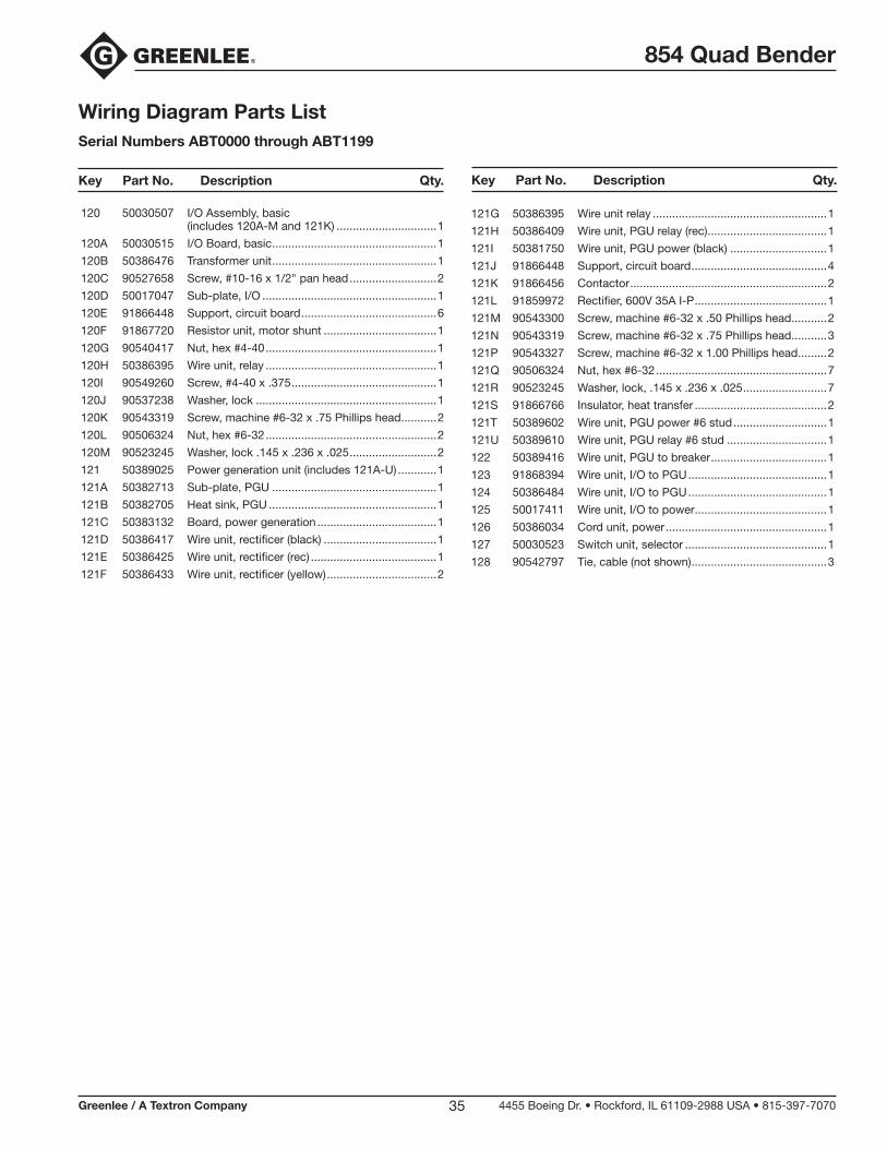
854 Quad Bender
Greenlee / A Textron Company 4455 Boeing Dr. • Rockford, IL 61109-2988 USA • 815-397-707035
Wiring Diagram Parts ListSerial Numbers ABT0000 through ABT1199
120 50030507 I/O Assembly, basic (includes 120A-M and 121K) ...............................1
120A 50030515 I/O Board, basic ...................................................1
120B 50386476 Transformer unit ...................................................1
120C 90527658 Screw, #10-16 x 1/2" pan head ...........................2
120D 50017047 Sub-plate, I/O ......................................................1
120E 91866448 Support, circuit board ..........................................6
120F 91867720 Resistor unit, motor shunt ...................................1
120G 90540417 Nut, hex #4-40 .....................................................1
120H 50386395 Wire unit, relay .....................................................1
120I 90549260 Screw, #4-40 x .375 .............................................1
120J 90537238 Washer, lock ........................................................1
120K 90543319 Screw, machine #6-32 x .75 Phillips head ...........2
120L 90506324 Nut, hex #6-32 .....................................................2
120M 90523245 Washer, lock .145 x .236 x .025 ...........................2
121 50389025 Power generation unit (includes 121A-U) ............1
121A 50382713 Sub-plate, PGU ...................................................1
121B 50382705 Heat sink, PGU ....................................................1
121C 50383132 Board, power generation .....................................1
121D 50386417 Wire unit, rectificer (black) ...................................1
121E 50386425 Wire unit, rectificer (rec) .......................................1
121F 50386433 Wire unit, rectificer (yellow) ..................................2
121G 50386395 Wire unit relay ......................................................1
121H 50386409 Wire unit, PGU relay (rec) .....................................1
121I 50381750 Wire unit, PGU power (black) ..............................1
121J 91866448 Support, circuit board ..........................................4
121K 91866456 Contactor .............................................................2
121L 91859972 Rectifier, 600V 35A I-P .........................................1
121M 90543300 Screw, machine #6-32 x .50 Phillips head ...........2
121N 90543319 Screw, machine #6-32 x .75 Phillips head ...........3
121P 90543327 Screw, machine #6-32 x 1.00 Phillips head .........2
121Q 90506324 Nut, hex #6-32 .....................................................7
121R 90523245 Washer, lock, .145 x .236 x .025 ..........................7
121S 91866766 Insulator, heat transfer .........................................2
121T 50389602 Wire unit, PGU power #6 stud .............................1
121U 50389610 Wire unit, PGU relay #6 stud ...............................1
122 50389416 Wire unit, PGU to breaker ....................................1
123 91868394 Wire unit, I/O to PGU ...........................................1
124 50386484 Wire unit, I/O to PGU ...........................................1
125 50017411 Wire unit, I/O to power .........................................1
126 50386034 Cord unit, power ..................................................1
127 50030523 Switch unit, selector ............................................1
128 90542797 Tie, cable (not shown) ..........................................3
Key Part No. Description Qty. Key Part No. Description Qty.
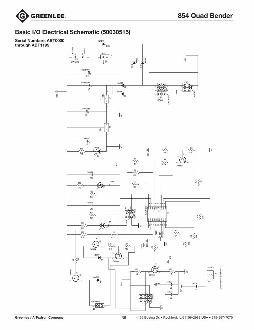
854 Quad Bender
Greenlee / A Textron Company 4455 Boeing Dr. • Rockford, IL 61109-2988 USA • 815-397-707036
Basic I/O Electrical Schematic (50030515)Serial Numbers ABT0000 through ABT1199
E
B
M
+-
GND
1K
R11
R9
1K
R10
1K
GND
Jumper W
ire Across Pins 2 & 3
123
JP1
Black
White
Red
UNLOAD
BEND
TO DIR SWITCH
X1
4.0Mhz
+5V
+5V
4 312
J3
10RB4
11RB5
12RB6
13RB7
14VDD
15OSC2
16OSC1
17RA0
18RA1
9RB3
8RB2
7RB1
6RB0
5VSS
4R
LC
3RTCC
2RA3
1RA2
PIC16C620
U2
DIR A
TO RELAY COIL
CE
GND
C
2N3906
2 1
J4
D7
RedAm
ber
DIR B
R191K
B
Q5
2N3904
R16
220
R18
22K
CE
B
Q4
2N3904
D6
1N4007
R14
3.3K
Q3
1N4007
R13
1K
R17
220
C11
.1u/50V
10k
R20
R21
10k
C10
.1u/50V
D5D4
TO PGU
GND
GND.1u/50V
C8
.1u/50V
C9
+12V
63
52
41
J2
R12
1.8K GND
+12V R7
10K
R8
220
CE
B
Q2
2N3904
R4
220
GND
C E
B
Q1
2N3906
R6
2.2M
R2
470K
R5
2.2M
R1
4.7K
+5VGreen
POWER
GND
C3
100uF/16V
1VI
2
G3
VO5V
U4C2
22uF/16V
D3
220
R15
+5V
TRANSFORMER
120 VAC IN
1 4
2 5
3 6
J102
MFJ6M
431
2
J101
GND
D2
1N5400
D1
1N5400
+12V
D102
1N5400
D101
1N5400
ELEC.
BRAKE
RELAY NO
RELAY COM White
Red
C101
4700uF/25V
1 C2 C
BRAKE SW.JP101
C4
4700uF/25V
1VI
2
G3
VO
12V U3
D103
1N5400
12
J103
C5
.1u/50V
+5V
R3
2.2K
R24
10KR23
10KR22
10K
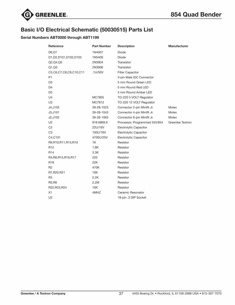
854 Quad Bender
Greenlee / A Textron Company 4455 Boeing Dr. • Rockford, IL 61109-2988 USA • 815-397-707037
Basic I/O Electrical Schematic (50030515) Parts ListSerial Numbers ABT0000 through ABT1199
Reference Part Number Description Manufacturer
D6,D7 1N4007 Diode
D1,D2,D101,D102,D103 1N5400 Diode
Q2,Q4,Q5 2N3904 Transistor
Q1,Q3 2N3906 Transistor
C5,C6,C7,C8,C9,C10,C11 .1U/50V Filter Capacitor
P1 3-pin Male IDC Connector
D3 5 mm Round Green LED
D4 5 mm Round Red LED
D5 5 mm Round Amber LED
U4 MC7805 TO-220 5 VOLT Regulator
U3 MC7812 TO-220 12 VOLT Regulator
J4,J103 39-28-1023 Connector 2-pin Minifit Jr. Molex
J3,J101 39-28-1043 Connector 4-pin Minifit Jr. Molex
J2,J102 39-28-1063 Connector 6-pin Minifit Jr. Molex
U2 918 6869.6 Processor, Programmed 555/854 Greenlee Textron
C2 22U/16V Electrolytic Capacitor
C3 100U/16V Electrolytic Capacitor
C4,C101 4700U/25V Electrolytic Capacitor
R9,R10,R11,R13,R19 1K Resistor
R12 1.8K Resistor
R14 3.3K Resistor
R4,R8,R15,R16,R17 220 Resistor
R18 22K Resistor
R2 470K Resistor
R7,R20,R21 10K Resistor
R3 2.2K Resistor
R5,R6 2.2M Resistor
R22,R23,R24 10K Resistor
X1 4MHZ Ceramic Resonator
U2 18-pin .3 DIP Socket
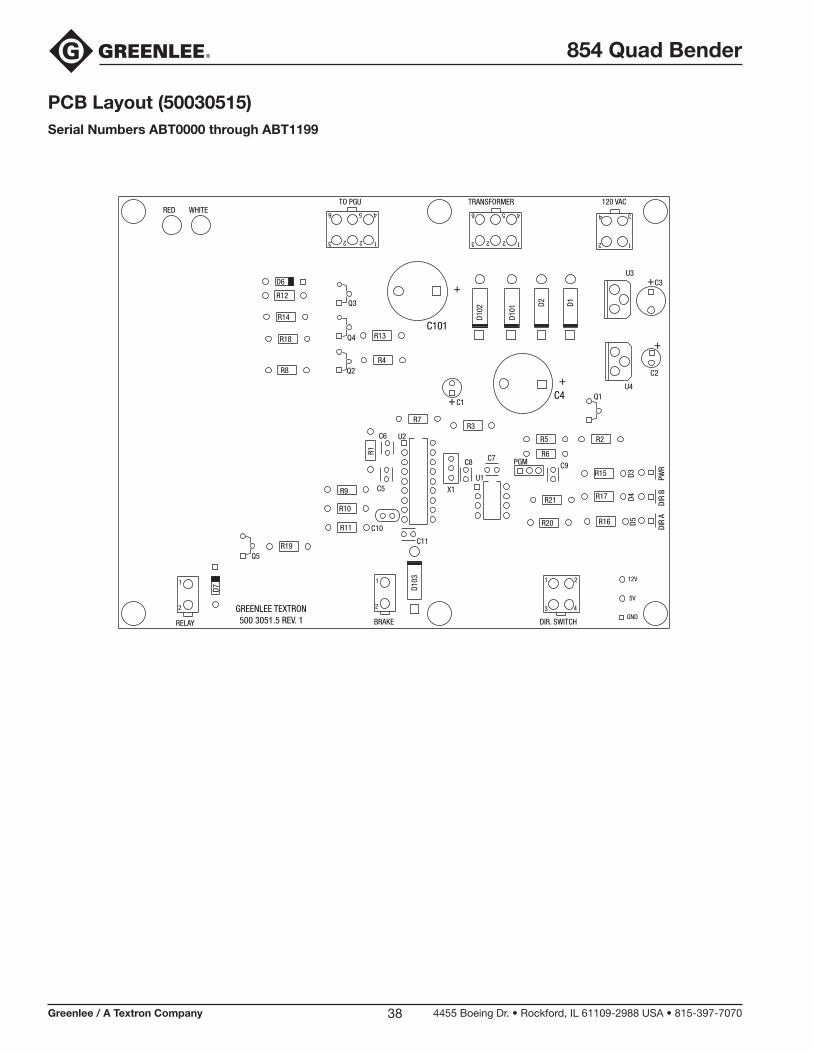
854 Quad Bender
Greenlee / A Textron Company 4455 Boeing Dr. • Rockford, IL 61109-2988 USA • 815-397-707038
PCB Layout (50030515)Serial Numbers ABT0000 through ABT1199
X1
DIR
BDI
R A
PWR
D5D4
D3
WHITERED
R13
R4R8 Q2
R7
R2
R6
R3
C1
R5
Q1
R18
R11
R9
R10
D6
Q3R12
R14
R19Q5
Q4
C5
C6
C7
U1
U2
C3
C2
U4
U3
C4
+
C101
+
D1
D102
D103
2
1 1 2
3 4
123
456
2 123
456
2 12
34
BRAKE
D101
D2
R15
R17
R16
R21
R20
2
1
GREENLEE TEXTRON
TO PGU
RELAY DIR. SWITCH
TRANSFORMER
PGM
500 3051.5 REV. 1
120 VAC
C10
C8 C9
R1
C11
GND
12V
5V
D7
+
+
+
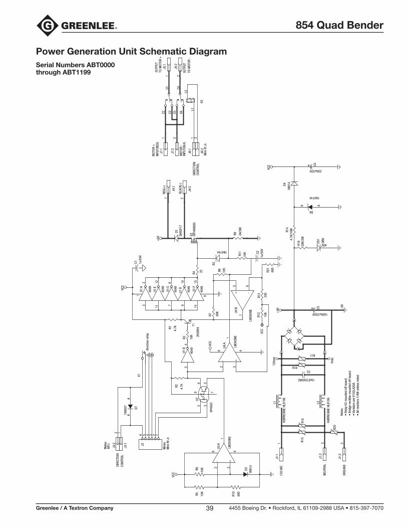
854 Quad Bender
Greenlee / A Textron Company 4455 Boeing Dr. • Rockford, IL 61109-2988 USA • 815-397-707039
Power Generation Unit Schematic DiagramSerial Numbers ABT0000 through ABT1199
J3:2
2
J3:1
1
U1:E
4049
1112
U1:B
4049
54
J5:1
1
J5:2
2
J7:2
2
J7:1
1
J4:1
1
J4:2
2
HP45
02
U22 3
786 5
J25 4 3 2 16
VCC
330u/25V
C4
1N91
4D4
4.7K
/10WR1
4
20K/
2WR1
9 GRN
DS1
L1
L2
C1C2 C3 C6C5
C4
U1:C
4049
76
U1:D
4049
910
VCC
U4:A
LM39
3NE1
8 4
+3
-2
R13
330
C1 1u/5
0V
R12
10K
R8 10K
R4 22
R7 68K
R3 10K
T12N
3904R1
4.7K
R2
4.7K
U1:F
4049
1415
U1:A
4049
32
VCC
+HV
VCC
120v
ac
U4:B
LM39
3NE
7
+5
-6
L1
HURR
ICAN
E HL
8196
R20
0vac
L2
HURR
ICAN
E HL
8196
R15
R16
R17
R18C3
10uF/250VAC
C5
1000u/250V
D31N
914
R10
680
R6
10K
R5 10K
VCC
LM39
3NE
U3:A
-2
+3
48
1
J6:1
1
J6:2
2
C21u
/50V
R11
10K
D2
1N4744
+HV
SKR2
F17
D1
Q2 IXFH
40N3
0
.04/
5W
R9
1N4744
D6AK
J1:1
1
J1:2
2
J1:3
3
D7
1N40
07K
A
dire
ctio
n re
lay
K1
81
INPU
T(BL
K)
INPU
T(RE
D)M
OTOR
+
OUTP
UT
OUTP
UT
TO M
OTOR
-
BLAC
K(-)
RED(
+)
MFJ
Mol
ex
MOT
OR -
-HV
CONT
ROL
DIRE
CTIO
N
GROU
ND
NEUT
RAL
120
VAC
K2
DIRE
CTIO
NCO
NTRO
L
Min
i-fit J
r.
Min
i-fit J
r.M
olex
TO M
OTOR
+
R21
680
Note
s:•
Rela
y K2
mou
nted
off-
boar
d.•
Brid
ge re
ctifi
er m
ount
ed o
ff-bo
ard.
• Va
risto
rs a
re V
150L
A20A
.•
All r
esis
tors
1/4
W u
nles
s no
ted.
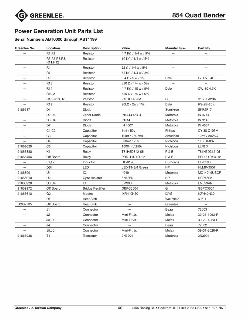
854 Quad Bender
Greenlee / A Textron Company 4455 Boeing Dr. • Rockford, IL 61109-2988 USA • 815-397-707040
Power Generation Unit Parts ListSerial Numbers ABT0000 through ABT1199
Greenlee No. Location Description Value Manufacturer Part No.
— R1,R2 Resistor 4.7 KΩ / 1/4 w / 5% — —
— R3,R5,R6,R8, Resistor 10 KΩ / 1/4 w / 5% — — R11,R12
— R4 Resistor 22 Ω / 1/4 w / 5% — —
— R7 Resistor 68 KΩ / 1/4 w / 5% — —
— R9 Resistor .04 Ω / 5 w / 1% Dale LVR-5 .04Ω
— R13 Resistor 330 Ω / 1/4 w / 5% — —
— R14 Resistor 4.7 KΩ / 10 w / 5% Dale CW-10 4.7K
— R10,21 Resistor 680 Ω / 1/4 w / 5% — —
— R15–R18,R20 Varistor V15 0 LA 20A GE V150 LA20A
— R19 Resistor 20kΩ / 2w / 1% Dale RS-2B-20K
91866871 D1 Diode — Semikron SKR2F17
— D2,D6 Zener Diode IN4744-DO-41 Motorola IN 4744
— D3,D4 Diode IN914 Motorola IN 914
— D7 Diode IN 4007 Motorola IN 4007
— C1,C2 Capacitor 1mf / 50v Philips CY-30 C105M
— C3 Capacitor 10mf / 250 VAC American 10mf / 20VAC
— C4 Capacitor 330mf / 25v Nichicon 1E331MPA
91868629 C5 Capacitor 1000mf / 250v Nichicon LLR2D
91866880 K1 Relay T81H5D312-05 P & B T81H5D312-05
91866456 Off Board Relay PRD-11DYO-12 P & B PRD-11DYU-12
— L1,L2 Inductor HL-8196 Hurricane HL-8196
— DSI LED LED T1-3/4 Green HP HLMP-3507
91866901 U1 IC 4049 Motorola MC14049UBCP
91866910 U2 Opto-Isolator 6N136N HP HCP4502
91866928 U3,U4 IC LM393 Motorola LM393AN
91859972 Off Board Bridge Rectifier GBPC3504 GI GBPC3504
91868610 Q2 Mosfet IXFH40N30 IXYS IXFH40N30
— D1 Heat Sink — Wakefield 695-1
50382705 Off Board Heat Sink — Greenlee —
— J1 Connector — Beau 72503
— J2 Connector Mini-Fit Jr. Molex 39-28-1063-P
— J3,J7 Connector Mini-Fit Jr. Molex 39-28-1023-P
— J4 Connector — Beau 72502
— J5,J6 Connector Mini-Fit Jr. Molex 39-01-2020-P
91866936 T1 Transistor 2N3904 Motorola 2N3904
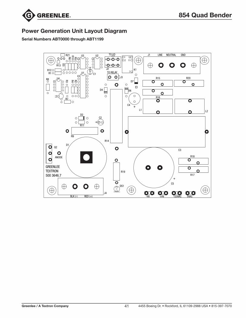
854 Quad Bender
Greenlee / A Textron Company 4455 Boeing Dr. • Rockford, IL 61109-2988 USA • 815-397-707041
Power Generation Unit Layout DiagramSerial Numbers ABT0000 through ABT1199
D2
+R11
R9
D1Q2
ANODE
R14
C3
L2
R18
R17+
C5
C2
-HV +HV 120VAC 0VAC
R19
DS1
J4BLK (-)
GREENLEETEXTRON500 3646.7
RED (+)
U3 U2 TO I/O
J2TO RELAY
J3
K1
R15
J1 LINE NEUTRAL GND
R20
R16
L1+C4
D7
D6
12
7
1211
U1
R13
U4R8
R7
R12R1
R5R2R4R3
T1
R10R6
D3
C1
+
D4
1
1 2 3
6 5 4
R21
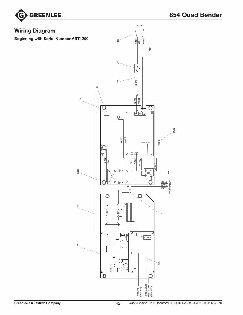
854 Quad Bender
Greenlee / A Textron Company 4455 Boeing Dr. • Rockford, IL 61109-2988 USA • 815-397-707042
Wiring DiagramBeginning with Serial Number ABT1200
23
4712
612
2
123
121
120A
120B
120
120C
120D
BLAC
K
GREE
NJP
1
CN1
CN2
YELL
OW
YELL
OW
YELLOW
AC
AC-HV
+HV
WHI
TE
WHI
TE
RED
BLAC
K
YELLOW
FROM RECTIFIER
RED BLACK
BLAC
K
TO R
ELAY
TO I/O
RED
BLAC
K
WHI
TE
BLAC
KBL
ACK
WHI
TE
GREE
N
TO D
RIVE
UNI
T
BLACKWHITE
GREEN
TO B
RAKE
(ITEM
#51
)
TO S
ELEC
TOR
SWIT
CH U
NIT
(ITEM
#12
7)
RED

854 Quad Bender
Greenlee / A Textron Company 4455 Boeing Dr. • Rockford, IL 61109-2988 USA • 815-397-707043
Wiring Diagram Parts ListBeginning with Serial Number ABT1200
120 50060180 854 I/O Control Assembly....................................1
120A 50060376 Wire Unit, Power — DC .......................................1
120B 50060368 Wire Unit, Power — AC .......................................1
120C 50386484 Wire Unit, I/O — PGU ..........................................1
120D 50060406 Wire Unit, Ground ................................................1
121 50054678 PGU2 Assembly...................................................1
122 50389416 Wire Unit, PGU to Breaker ...................................1
123 91868394 Wire Unit, I/O to PGU ..........................................1
126 50386034 Cord Unit, Power .................................................1
127 50030523 Switch, PCB Direction .........................................1
128 90542797 Tie, Cable (not shown) .........................................3
Key Part No. Description Qty.

854 Quad Bender
Greenlee / A Textron Company 4455 Boeing Dr. • Rockford, IL 61109-2988 USA • 815-397-707044
I/O Electrical Schematic (50060180)Beginning with Serial Number ABT1200
Note
: Al
l res
isto
rs 5
% 1
/4W
unl
ess
note
d.
+5V
+12
V
+12
V
+5V
+12
V
+5V
+12
V+
12V
+5V
+5V
RUN/
BRAK
E
_RUN
/BRA
KE_
_DIR
ECTI
ON_
_PW
M_
DIR
BDI
R A
PWM
DIRE
CTIO
N
MEC
H BR
AKE
UNUS
ED2
UNUS
ED1
65
43
21 TO
PGU
Mol
ex 3
9-28
-106
3
JP5
54321
DC P
OWER
INM
olex
26-
60-4
050
JP1
18RA
1/AN
1
17RA
0/AN
0
16OS
C1/C
LKIN
15OS
C2/C
LKOU
T
13RB
7
12RB
6
11RB
5
10RB
4
9RB
3
8RB
2
7RB
1
6RB
0/IN
T
4M
CLR
3RA
4/TO
CKI
2RA
3/AN
3
1RA
2/AN
2/VR
EF
PIC1
6C62
0
U1
10K
R23
10K
R22
UF10
01DI
D1
UF-1
001-
DID5
UF-1
001-
DID4
1N41
48D3
PN22
22A
Q4PN
2222
AQ3
PN22
22A
Q2
POW
ERGR
EEN
LED
D2
DIR
BAM
BER
LED
D7
DIR
ARE
D LE
DD6
10K
R18
.1uF
/50V
C1
330
R6
21
RELA
Y CO
ILM
olex
39-
28-1
023
JP3
21
MEC
HANI
CAL
BRAK
EM
olex
39-
28-1
023
JP2
470
R5
TIP1
22Q1
150
R10
43
21
PEND
ANT
Mol
ex 3
9-28
-104
3
JP4
.1uF
/50V
C4
330
R21
.1uF
/50V
C3
330
R20
10K
R17
10K
R16
10K
R15
31
2
4.0
MHz
X1
10K
R7
10K
R410
KR3
10K
R210
KR1
470
R14
1KR19
470
R13
150
R12
470
R11
4.7u
F/50
VC2
1KR9
10K
R8
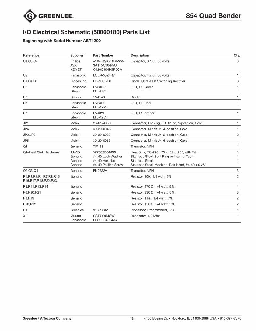
854 Quad Bender
Greenlee / A Textron Company 4455 Boeing Dr. • Rockford, IL 61109-2988 USA • 815-397-707045
I/O Electrical Schematic (50060180) Parts ListBeginning with Serial Number ABT1200
Reference Supplier Part Number Description Qty.
C1,C3,C4 Philips A104K29X7RFVVWN Capacitor, 0.1 uF, 50 volts 3 AVX SA115C104KAA KEMET C420C104K5R5CA
C2 Panasonic ECE-A50Z4R7 Capacitor, 4.7 uF, 50 volts 1
D1,D4,D5 Diodes Inc. UF-1001-DI Diode, Ultra-Fast Switching Rectifier 3
D2 Panasonic LN38GP LED, T1, Green 1 Liteon LTL-4231
D3 Generic 1N4148 Diode 1
D6 Panasonic LN28RP LED, T1, Red 1 Liteon LTL-4221
D7 Panasonic LN48YP LED, T1, Amber 1 Liteon LTL-4251
JP1 Molex 26-61-4050 Connector, Locking, 0.156" cc, 5-position, Gold 1
JP4 Molex 39-29-0043 Connector, Minifit Jr., 4-position, Gold 1
JP2,JP3 Molex 39-29-0023 Connector, Minifit Jr., 2-position, Gold 2
JP5 Molex 39-29-0063 Connector, Minifit Jr., 6-position, Gold 1
Q1 Generic TIP122 Transistor, NPN 1
Q1–Heat Sink Hardware AAVID 577002B04000 Heat Sink, TO-220, .75 x .52 x .25", with Tab 1 Generic #4-40 Lock Washer Stainless Steel, Split Ring or Internal Tooth 1 Generic #4-40 Hex Nut Stainless Steel 1 Generic #4-40 Phillips Screw Stainless Steel, Machine, Pan Head, #4-40 x 0.25" 1
Q2,Q3,Q4 Generic PN2222A Transistor, NPN 3
R1,R2,R3,R4,R7,R8,R15, Generic Resistor, 10K, 1/4 watt, 5% 12 R16,R17,R18,R22,R23
R5,R11,R13,R14 Generic Resistor, 470 Ω, 1/4 watt, 5% 4
R6,R20,R21 Generic Resistor, 330 Ω, 1/4 watt, 5% 3
R9,R19 Generic Resistor, 1 kΩ, 1/4 watt, 5% 2
R10,R12 Generic Resistor, 150 Ω, 1/4 watt, 5% 2
U1 Greenlee 91869382 Processor, Programmed, 854 1
X1 Murata CST4.00MGW Resonator, 4.0 Mhz 1 Panasonic EFO-GC4004A4

854 Quad Bender
Greenlee / A Textron Company 4455 Boeing Dr. • Rockford, IL 61109-2988 USA • 815-397-707046
PCB Layout (50060180)Beginning with Serial Number ABT1200
Q1
JP1
R22
RELAYBRAKE
TO PGU
POWER
JP41
2
34
JP5
12
3
45
6
R15
R1
D4
R21
C4
R18
D7
DIR A
JP3
1 2
Q3
R13
R8
R9
C2+
D3
R5
DIR B
JP2
1
2
R6
C1
D2
X1
D1
R20
C3
D6
R17
D5
R11
R12
R19
R14
R10
Q2
Q4
R23
U1
SELE
CTOR
R3
R4
R7
GREENLEE TEXTRON ©2000
R2
R16
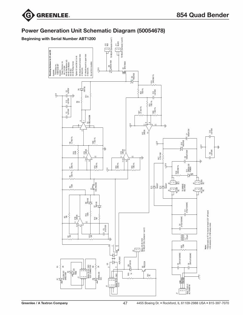
854 Quad Bender
Greenlee / A Textron Company 4455 Boeing Dr. • Rockford, IL 61109-2988 USA • 815-397-707047
Power Generation Unit Schematic Diagram (50054678)Beginning with Serial Number ABT1200
Do n
ot tr
im in
sula
tor.
in h
eat s
ink.
Q1 s
houl
d m
ount
to u
pper
hol
e
in h
eat s
ink.
D8 s
houl
d m
ount
to lo
wer
hol
e
Tigh
ten
Q1 a
nd D
8 to
5 in
-lb
#4-4
0 Ph
illip
s Sc
rew
#4-4
0 Nu
t#4
-40
Lock
Was
her:
#4-4
0 Fl
at W
ashe
r (x2
)
KA-1
18-0
94
Pow
er D
evic
es, I
ncIn
sula
tor:
TH
M70
23B-
MT
Th
erm
allo
y In
c.He
atsi
nk:
Mou
ntin
g Ha
rdw
are
for Q
1 an
d D8
7
54
81
62
MIC
4422
BNU2
100K
R10
-+
123
167
LM33
9U1
A
10K/
1%R1
6
20K/
1%R7
4.75
K/1%
R6 1.5K
/1%
R26
+15
V 20K/
1%R2
4
10K/
1%R2
5
-+
123
131011
LM33
9U1
D
+17
0 V
1N52
45B
D3
21
TO R
ELAY
(Con
tact
s 5
and
8)
BLAC
KJ1
1
21
TO R
ELAY
(Con
tact
s 6
and
7)
RED
J10
DSEI
30-0
6AD8
IXFK
73N3
0Q1
C10
+15
V
.1uF
/50V
.1uF
/50V
C9
VCC
GREE
N LE
D
D4DIRE
CTIO
NYE
LLOW
LED
D1
PWM
RED
LED
D2
2KR82KR1
65
43
21 TEST
CON
NECT
ORM
olex
39-
28-1
063
J1
EVQ-
PAC0
9K
S1
-+
123
245
LM33
9U1
B
100K
R13
1N41
48D6
1MR12
1N41
48D7
1MR14
.01u
F/50
VC3
150K
R41MR2
1MR3
12K/
1%R5
+15
V
27.4
K/1%
R27
1.5K
/1%
R28
.1uF
/50V
C12
10K/
1%R2
3-+ 123
1489
LM33
9U1
C10
0/1%
R22
.040
/5W
/1%
R15
2 35678
2 1
TO R
ELAY
COI
L (C
onta
cts
1 an
d 2)
Mol
ex 3
9-28
-102
3
J4
UF10
01DI
D9
HCPL
4502
U3
65
43
21
TO I/
OM
olex
39-
28-1
063
J2
PN22
22A
Q2
1KR19
1KR21
+15
V
.1uF
/50V
C13
.1uF
/50V
C11u
F/63
VC2 1N
4148
D522R9
22R11
RECT
IFIE
RTO
BRI
DGE
+17
0 V
+15
V1N
4007
D13
1N40
07
D14
21
ACYE
LLOW
J8
4.7K
/10W
R17
21
DC-
BLAC
K
J9
21
DC+
RED
J6
21
ACYE
LLOW
J5
POW
ERGR
EEN
LED
D11
1N52
45B
D10
20K/
2W/1
%R1
8
680u
F/25
VC7
1000
uF/2
50V
C6
.010
uF/5
00VA
CC4
.010
uF/5
00VA
CC1
1GR
OUND
NEUT
RAL
LINE
.004
7uF/
500V
ACC5 .0
047u
F/50
0VAC
C847
0uH
L11.
5MR2
03 2 1
AC P
OWER
INBe
au 7
2503
-C
J7
Note
s:•
Bend
lead
s on
R17
to m
ount
at l
east
0.2
5" o
ff-bo
ard.
•Al
l res
isto
rs 5
% 1
/4W
unl
ess
note
d.
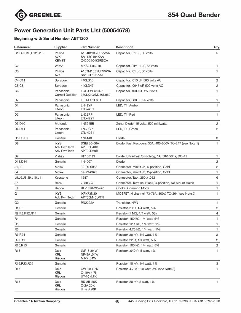
854 Quad Bender
Greenlee / A Textron Company 4455 Boeing Dr. • Rockford, IL 61109-2988 USA • 815-397-707048
Power Generation Unit Parts List (50054678)Beginning with Serial Number ABT1200
C1,C9,C10,C12,C13 Philips A104K29X7RFVVWN Capacitor, 0.1 uF, 50 volts 5 AVX SA115C104KAA KEMET C420C104K5R5CA
C2 WIMA MKS21.06310 Capacitor, Film, 1 uF, 63 volts 1
C3 Philips A103M15Z5UFVVWA Capacitor, .01 uF, 50 volts 1 AVX SA105E103ZAA
C4,C11 Sprague 440LS10 Capacitor, .010 uF, 500 volts AC 2
C5,C8 Sprague 440LD47 Capacitor, .0047 uF, 500 volts AC 2
C6 Panasonic ECE-S2EU102Z Capacitor, 1000 uF, 250 volts 1 Cornell Dubilier 380LX102M250K052
C7 Panasonic EEU-FC1E681 Capacitor, 680 uF, 25 volts 1
D1 Panasonic LN48YP LED, T1, Amber 1 Liteon LTL-4251
D2 Panasonic LN28RP LED, T1, Red 1 Liteon LTL-4221
D3,D10 Motorola 1N5245B Zener Diode, 15 volts, 500 milliwatts 2
D4,D11 Panasonic LN38GP LED, T1, Green 2 Liteon LTL-4231
D5,D6,D7 Generic 1N4148 Diode 3
D8 IXYS DSEI 30-06A Diode, Fast Recovery, 30A, 400-600V, TO-247 (see Note 1) 1 Adv Pwr Tech APT30D40B Adv Pwr Tech APT30D60B
D9 Vishay UF1001DI Diode, Ultra-Fast Switching, 1A, 50V, 50ns, DO-41 1
D13,D14 Generic 1N4007 Diode 2
J1,J2 Molex 39-29-0063 Connector, Minifit Jr., 6-position, Gold 2
J4 Molex 39-29-0023 Connector, Minifit Jr., 2-position, Gold 1
J5,J6,J8,J9,J10,J11 Keystone 1287 Connector, Tab, .250 x .032 6
J7 Beau 72503-C Connector, Terminal Block, 3-position, No Mount Holes 1
L1 Renco RL-1328-22-470 Choke, Common Mode 1
Q1 IXYS IXFK73N30 MOSFET, N channel, 73-76A, 300V, TO-264 (see Note 2) 1 Adv Pwr Tech APT30M40LVFR
Q2 Generic PN2222A Transistor, NPN 1
R1,R8 Generic Resistor, 2 kΩ, 1/4 watt, 5% 2
R2,R3,R12,R14 Generic Resistor, 1 MΩ, 1/4 watt, 5% 4
R4 Generic Resistor, 150 kΩ, 1/4 watt, 5% 1
R5 Generic Resistor, 12.1 kΩ, 1/4 watt, 1% 1
R6 Generic Resistor, 4.75 kΩ, 1/4 watt, 1% 1
R7,R24 Generic Resistor, 20 kΩ, 1/4 watt, 1% 2
R9,R11 Generic Resistor, 22 Ω, 1/4 watt, 5% 2
R10,R13 Generic Resistor, 100 kΩ, 1/4 watt, 5% 2
R15 Dale LVR-5 .04W Resistor, .040 Ω, 5 watt, 1% 1 KRL NP-5A .04W Riedon MT-5 .04W
R16,R23,R25 Generic Resistor, 10 kΩ, 1/4 watt, 1% 3
R17 Dale CW-10 4.7K Resistor, 4.7 kΩ, 10 watt, 5% (see Note 3) 1 KRL C-10A 4.7K Riedon UT-10 4.7K
R18 Dale RS-2B-20K Resistor, 20 kΩ, 2 watt, 1% 1 KRL C-2A 20K Riedon UT-2B 20K
Reference Supplier Part Number Description Qty.
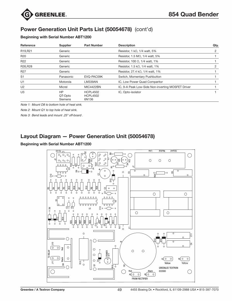
854 Quad Bender
Greenlee / A Textron Company 4455 Boeing Dr. • Rockford, IL 61109-2988 USA • 815-397-707049
Layout Diagram — Power Generation Unit (50054678)Beginning with Serial Number ABT1200
Power Generation Unit Parts List (50054678) (cont’d)Beginning with Serial Number ABT1200
Reference Supplier Part Number Description Qty.
R19,R21 Generic Resistor, 1 kΩ, 1/4 watt, 5% 2
R20 Generic Resistor, 1.5 MΩ, 1/4 watt, 5% 1
R22 Generic Resistor, 100 Ω, 1/4 watt, 1% 1
R26,R28 Generic Resistor, 1.5 kΩ, 1/4 watt, 1% 2
R27 Generic Resistor, 27.4 kΩ, 1/4 watt, 1% 1
S1 Panasonic EVQ-PAC09K Switch, Momentary Pushbutton 1
U1 Motorola LM339AN IC, Low Power Quad Comparitor 1
U2 Micrel MIC4422BN IC, 9-A Peak Low-Side Non-inverting MOSFET Driver 1
U3 HP HCPL4502 IC, Opto-isolator 1 QT-Opto HCPL4502 Siemens 6N136
Note 1: Mount D8 to bottom hole of heat sink.
Note 2: Mount Q1 to top hole of heat sink.
Note 3: Bend leads and mount .25" off-board .R1
8
L1
J7
Q1
+
C6D8
C13
C12
C10
C3
C1
C9
C2
U1
J6
YellowYellow
Red Black
TEST
DIR
PWM
VCC
GREENLEE TEXTRON
POW
ER
R17
65
4
32
1
D2
R8R1
D1
J8J5
J9
D4
R15
D11
D13
Red
Blac
kTO R
ELAY
FROM RECTIFIER
©2000
TO I/O GroundNeutralLine
R28
R12
R4
R22
R2
R27
R3
6 5 4
3 2 1
J2
C4
21
J4
R7
D3
R16
R6R2
3
R10
Q2
U3
R13
R14
D6D7
U2
R26
D5
R9 R11
R5
R24
R25
R19
R21
C5 C8
R20
C11
+
C7
S1
D9
D10
J10
J11
D14