8500 culebra road, san antonio, rexas 78206 studies of ... · southwest research institute 8500...
TRANSCRIPT

SOUTHWEST RESEARCH INSTITUTE8500 Culebra Road, San Antonio, rexas 78206
STUDIES OF INTERNAL DISPLACEMENTS INSOLID PROPELLANT GRAINS
(Elastomeric Strain Transducer)
*. J. D. MichieL. U. Rastrelli
R. C. DeHart
Project 03-1043Contract Nr. Nonr-3363(00)(FBM)
Nr. 064-451/1-31-64
Prepared for
Structural Me-hanics BranchOffice of Naval Research
Washington 25, D.C.
- D20 March 1965 SEP • 1912
ALPPFROVED-
NATIONAL TECHNICAL " "INFOPMATION SERVICE Roberm C. De.Har- Direc:or
I I DeparIlir rdt -," 1;rti :rzir .•r ca r"
Thadocument hcze b.. ppm4
:wPublic te~w (m"d mwdarbui2Ls21rmb

FOREWORD
The work described in this report was performed under Contract
Nr. Nonr-3363(00)(FBM) Nr. 064-451/1-31-64 for the Office of Naval
Research, Structural Mechanics Branch. The program's overall objec-
tive is to develop procedures for measuring internal strains in solid pro-
pellant grains. The information presented describes an elastomeric
strain transducer development for utilization on high elongation materials.
The authors gratefully acknowledge the contribution of Mr. E.
Anderson and Mr. R. Guerra for their as sstance in the design, fabrica-
tion and testing of the prototype gages.
I,

ABSTRACT
"The transducer discussed in this report is a device that measures
strain (up to 50 per cent) on viscoelastic materials such as the binder
used in solid-propellant motors. The transducer is designed for surface
mounting although the basic gage concept is also applicable to a device
which can be embedded within a material. The active element is a mer-
cury base fluid column of 6-mil diameter and 0. 5-inch lengths. Complete
Ainformation is presented regarding the transducer construction, calibra-
tion and evaluation testing.
IJ

TABLE OF CONTENTS
LIST OF ILLUSTRATIONS
I. INTRODUCTION 1
II. GAGE DESIGN AND FABRICATION 6
III. READOUT INSTRUMENTATION 11
IV. CALIBRATION PROCEDURE 14
V. PRELIMINARY EVALUATIONS 19
,, ji-

LIST OF ILLUSTRATIONS
FigurePage
1 CONCEPTUAL ELASTOMERIC STRAIN GAGEPROTOTYPES 3
2 GAGE RESISTANCE VERSUS STRAIN FOR UN-AXIAL ELASTOMERIC TRANSDUCER IN TENSION 4
3 GAGE RESISTANCE VERSUS MODULE DEFLEC-TION FOR TRIAXIAL TRANSDUCER 5
4 ELASTOMERIC STRAIN GAGE "A", DESIGNDRAWING 7
5 ELASTOMERIC GAGE MOLD PRIOR TO CASTING 8
6 TRANSDUCER ASSEMBLING MOLD FIXTURE 10
7 KELVIN BRIDGE CIRCUIT DIAGRAM 12
8 KELVIN BRIDGE 13
9 ELASTOMEP.IC GAGE CALIBRATION EXTENSIO.-METER 15
10 TYPICAL RESISTANCE VERSUS GAGE ELONGA-TION PLOT 16
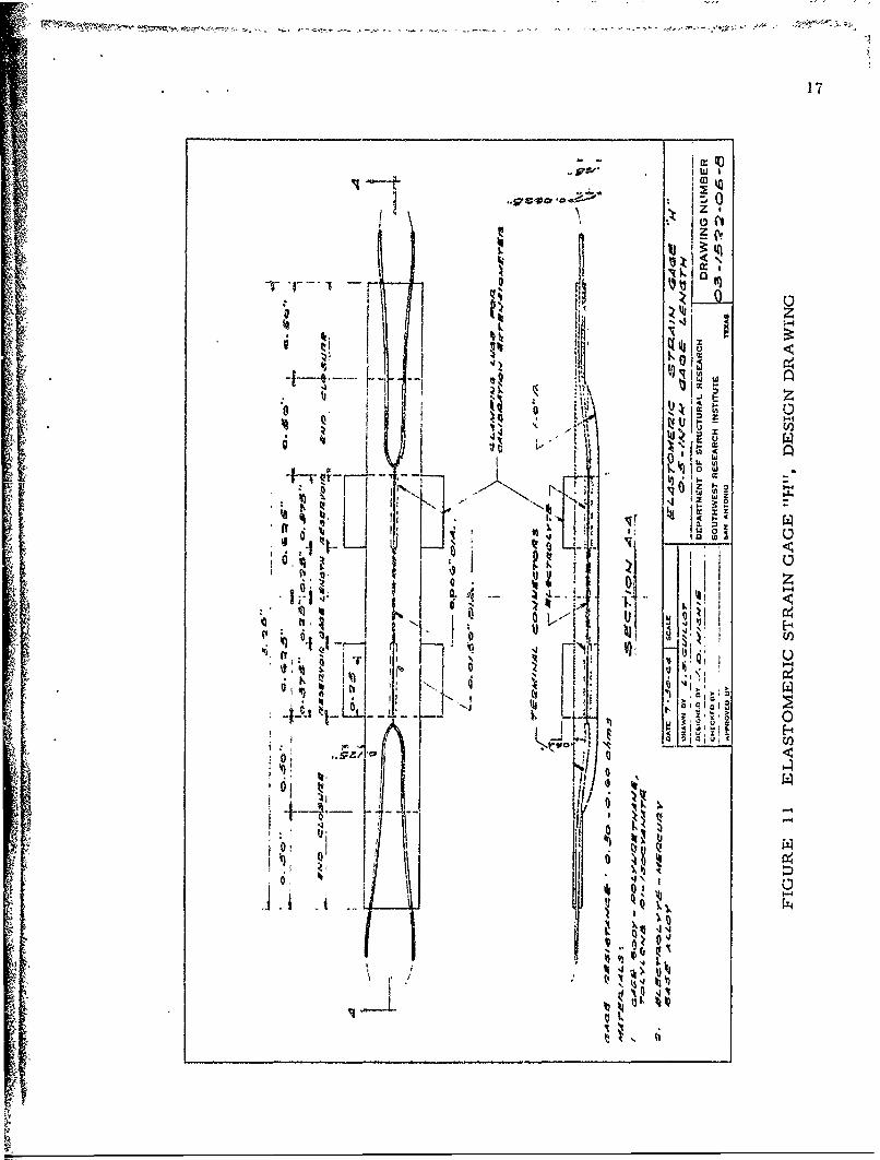
11 ELASTOMERIC STRAIN GAGE "H". DESIGNDRA WING 17
12 STRAIN TRANSDUCER PROTOTYPES: ORIGINAL(UPPER) AND MODIFIED(LOWER) DESIGN 18
13 FREQUENCY DISTRIBUTION OF GAGE RESIS-TANCE (0.5 INCH GAGE LENGTH). 21
14 FREQUENCY DISTRIBUTION OF SLOPES FORRESISTANCE VERSUS GAGE ELONGATION CURVES 22
15 TYPICAL PLOT OF GAGE RESISTANCE VERSUSTEMPERATURE (FOUR CYCLES) 25
16 TYPICAL PLOT OF GAGE RESISTANCE VERSUSPNEUMATIC PRESSURE (TWO CYCLES) 26
IL

1. INTRODUCTiON
In recent years the need for a device that could measure high
elongation strains present in viscoelastic materials (such as solid pro-
pellant grains) has become apparent. Conventional methods for measur-
ing surface strains on elastic, metallic materials have proved ineffective
when applied to the high elongations prevalent in viscoelastic bodies Thls
can be attributed to two basic limitations: (1) the present strain measuring
devices (such as wire or foil electrical resistant gages) have a low useful
strain range (less than ten per cent); and (2) the reinforcing effect of a
relatively rigid metallic gage mounted on the flex.ble viscoelastic member
distorts the strain field under investigation. For these reasons it became
evident that new techniques or innovations were required to satisfactorily
retrieve structural and mechanical response intelligence from members
in the rapidly expanding field of viscoelasticity.
Several new strain measo.ring concepts which indicated the poten-
tial for measuring strains of large magnitude were formulated. After a
brief analytical evaluation, the most promising concept was selected for
further study. In order to demonstrate the concept's validity, a concep-
tual prototype gage was designed and fabricated. This initial config-
uration consisted of a small inside diameter. thick-wall elastomeric
tube filled with an electrical conducting fluid As expected the elec-
trical resistance of '.he conducting fluid column changed as the elasto-
meric tube was axi Mly deformed. tHls change in gage res:stance was
- ,

2
determined to be proportional (and nearly linear) to extensional deforma-
tions. Also, the prototype exhibited clearly discernible and measurable
phenomenon for elongations up to forty percent.
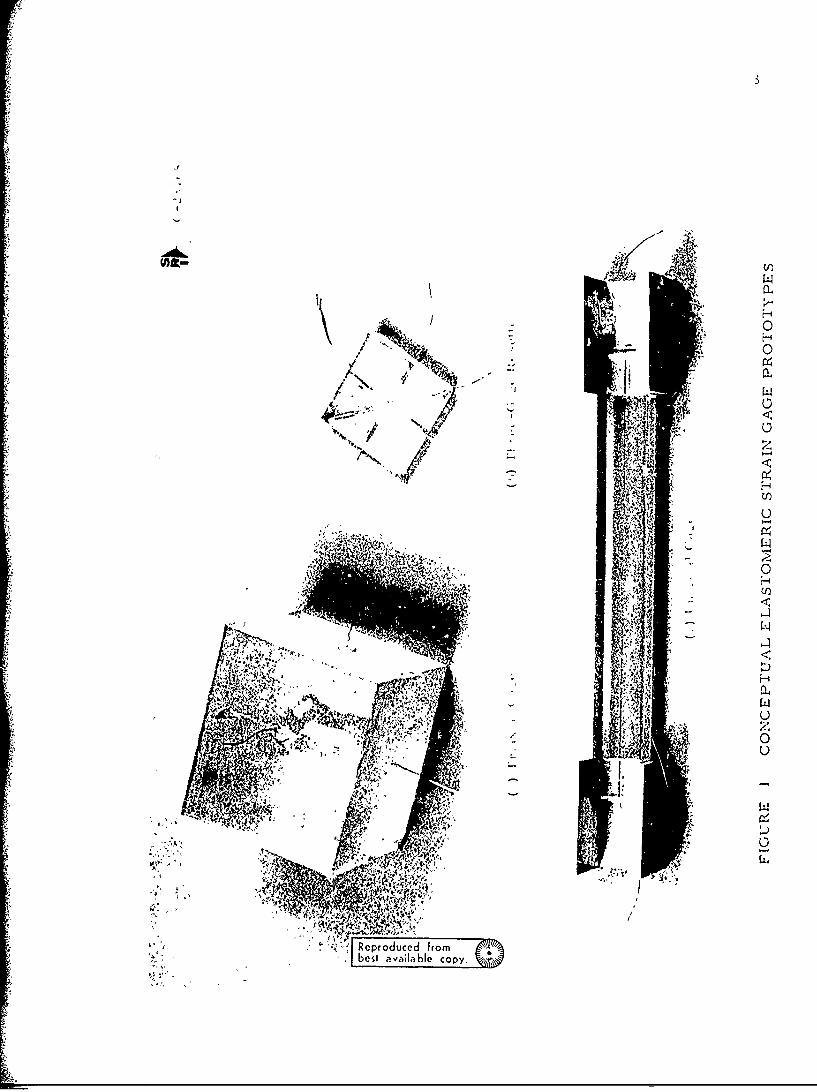
Three exploratory models are pictured in Figure 1; the triaxial
module (a) consists of three orthogonal gages, the rosette (b) consists of
three coplaner (non-intersecting) gages and the uniaxial module (c) con-
sists of the single active column (the aluminum channel at the ends of the
uniaxial gage were bonded to the module to facilitate gripping during testing).
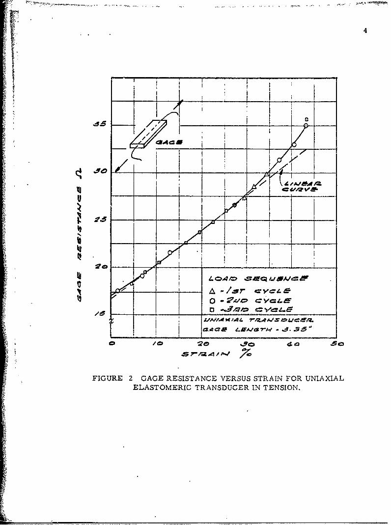
Typical results of module testing are indicated in Figures 2 and 3. In Fig-
ure L, the linear relationship between strain and resistance change is de-
picted for the uniaxial module in tension. In Figure 3, a ,Limilar relation-
ship is shown for the triaxial module (Figure la) in compression; gages
2 and 3 reflect the Poisson effect,
Due to these promising indications, further effort was devoted to
exploring the concept's potential and developing a practical high elongation
strain transducer. A general review of the progress which has been made
is presented in the following discussion.
-1
Efl~-U)
V.,.
" MN";
best av ia l Copy
4
I I I
V i
• : i
ELS I TRASUE IN TENION.
• • '
~FIGURE 2 GAGE RESISTANCE VERSUS STRAIN FOR UNIAXiALS~ELASTOMERIC TRANSDUCER IN TENSION.
,A,
.j.

5
a , '1i
04 ca "40 12C
IIUR 3 I)'EITNE ESSLIDL DEFLECTION
FO IA- TRANSDUCER.
i• - j ]: i! -
I "I . ", : i ! " ,I I I C 77 ! / /'.' C , iFIC.RE CA '. r~ISAC VERSU • / + JL"DEFLECT"ON
,(FOR , RIA)A TRANSDUCER.
I /
6
I. GAGE DESIGN AND FABRICATION
A gage configuration (shown in Figure 4) was selected early in the
program to serve as a standard of comparison for the evaluation testing.
Although the elastomeric strain transdUcer concept is applicable to both a
surface mounted and an embedded gage, in the initial development studies
the surface mounted configuration was chosen because of (a) its more sturdy
construction, (b) the ease with which the gages could be attached and re-
moved fror- -nst articles used in the intermittant elongation-calibration
procedY.-oe;s and (c) its accessbility which greatly facilitates vi..,ial and
mecnaaical evaluation. A nominal gage length of 0. 5 inch" was used for
the initial prototype.
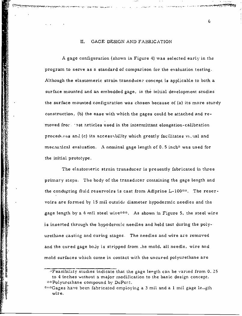
The elastomeric strain transducer is presently fabricated in three
primary steps. The body of the transduicer containing the gage length and
the condupting fluid reservoirs is cast from Adiprine L-100;:':. The reser-
voirs are formed by 15 mil outsidi: diameter hypodermic needles and the
gage length by a 6 mil steel wire***. As shown in Figure 5, the steel wire
is inserted through the hypodermic needles and held taut during the poly-
urethane casting and curing stages. The needles and wire are removed
and the cured gage body is stripped from he mold, all needle, wire and
mold surfaces which come in contact with the uncured polyurethane are
-'Feasibility studies indicate that the gage length can be varied from 0. 25
to 4 inches without a major modification to the basic design concept.""Polyurcthane compound by DuPort.
*:::Gages have been fabricated employing a 3 mil and a 1 mil gage le,,gthwire.

J w'.
I. 0
0 It
zF 0
'1,
hi..) A ~~ifg~I
I I 4

8
'�, �-
4. U
�I11ri�1
UiU,'UV
n 0
HU 0
VB'I
U
I
// Wi 0U
U
', Qg
14J'J�:m kk4 ii
/1�
/
�.1 '.1

9
coated with a teflon mold releasing agent prior to the casting operation. A
mercury base alloy is injected into the reservoirs and gage length cavity
with the necessary precautions to prevent entrapping of air or foreign parti-
cles. A two-wire terminal is inserted a precise distance into each reservoir
to establish a low resistant wire-to-conductive fluid contact and to insure a
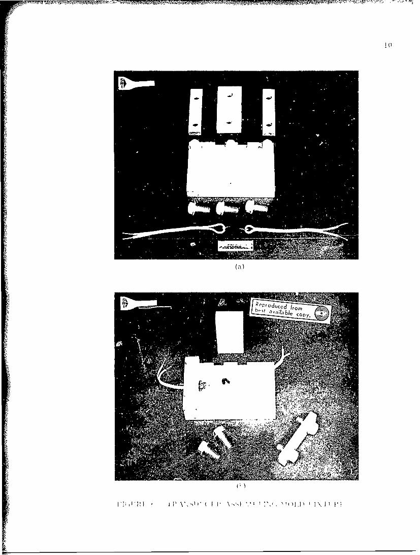
consistent, nominal electrical resistance across the gage length. The gage
body-lead wires composite is clamped into a mold fixture (Figure 6a) which
restrains any relative motion within the composite. A second casting of
polyurethane provides the seal for the conductive fluid and anchors the leads
to the gage body (Figure 6b). The completed gage is a sturdy device capa-
ble of sustaining normal laboratory handling without damage.
I¢
, ~ - --, -i-- - r
ocony.
Fir

III. READOUT INSTRUMENTATION
An important aspect of the elastomeric transducer concept is the
readout equipment and circuitry requi.:ed to detect and measure resistance
change in the gage. The strain transducer's relative low resistance (0 40
ohms for the 0. 5 inch gage length) is particularly applicable to a Kelvin
bridge circuit (see Figure 7).
"The principal feature of the Kelvin bridge is the cancellation of
lead wire resistance from the gage circuit by a balancing procedure Since
the nominal gage resistance is quite low, any error introduced into the mea-
suring circuit by resistance change in the lead wires would be critical.
A Kelvin bridge (Figure 8) was specially designed to accommodate
strain gages resistance measurement in the range of 0 to 20 ohms, the
bridge has proved to be stable and have a repeatable accuracy of 1/4 per-
cent for a I ohm reading. It is due to the peculiar Kelvin bridge circuit
requirement that the elastomeric strain transducer configuration has the
2-two wire connection detail. Nevertheless, the gage configuration is
applicable (without modification) to the less preferred Wheatstone bridge
circuit.

12
114 P404 04
00
0'
LnU
F, QHzS
P-4
10Z
Im

13
9',
0 ..
0
z~ U.
uV
00
I'.D
COPY4
IV. CALIBRATION PROCEDUR.E
The establishment of the elongation-resistance change relationship
for each prototype gage is performed with the aid of a micrometer dial
extenslomreter (Figure 9) The gages are positioned in the device, secured
by bar clamps and then elongated in precise incremental distances At
each increment, the electrical resistance across the strain transducer is
noted. With these data a calibration curve (Figure 10) is plotted which
indicates the elongation-resistance change characteristic of the particular
gage tested.
Newly manufactured gages are immediately calibrated as a first
proof test After each strain transducer evaluation (such as hydrostatic
and elevated temperature tests) the gage is chc,.ked in the extensiometer
to determine if any basic changes have occurred in the gage characteristics.
In positioning a gage in the extensiometer. it was determined the
clamping affected the electrical resistance To eliminate this factor the
gage's configuration was modified to include fouir lugs and is shown in
Figure 11. The normal force of the extensiometer clamping action bears
on the lugs. the ,age is e'ongated by shear force between the lugs and the
strain transducer body. Subsequent tests performed on the modified gage
indicated that the adverse effect of the extensiomter clamping action iad
'.,cn climinated The orriginil and mocldified strait ransducer protot~pes
rt'e shomn in I,• i gtre 12. The lugs (on the mn t'fi ed adgc) I, n be ea zflv re-I moved after - .;,ae ,s Mibraued if •t1edt )at -, , rt.,:t' ,n ohslru'tion

15
I C,'co
F
e
r r�j
1:7, N
Thg��&5
H01-4
5
AThOLNAS
N
0
Cl)N
l'I�Li
H
tt�-.
Nz1-40
H
4.
U
E 6 NUU
1 U'-4N
6 HCl)
I-i
IC' Na'
N
L bes' a�a'� bic copY�
.4
�cPr 0duCcd
�rom

THISPAGE
isMISSING
IN
ORIGINALDOu U IYUU N 1I
17
SI 1W I
A JO
;--- .---
11, i,, t .,
: • . ! • • , i •ii~0
oI *,,'U!
•i 0
_Q ._ • l
.-..- ,-IO
tI- •.z

18
00
N0
~z C
0
-*4
4-Pz
10 el4

1M
V. PRELIMINARY EVA"iJUATIONS
In order to establish the elastomeric strain transducer's perfor-
mance capability, a series of evaluation tests were devised and the proto-
type gages appraised according to their response
Nominal Resistance The nominal (non-strained) electrical resis-
tance within the first prototype gage group (the gages wre manufactured
in groups of six) was found to vary from 0. 30 to 1 10 ohms. The desir-
ability of fabricating gages with uniform mechanical properties was deemed
of utmost importance as a standard gage would provide L higher degree of
confidence and would greatly simplify the readout equipment and circuitry
The initial gage group was examined radiograpr'ically The exam-
ination clearly indicated the nominal resistance variatiuns could be attri-
buted to two basic factors: (1) the lead wire penetratioi distance differed
from gage to gage and (2) the gage capillary contained a~r bubbles within
the mercury base alloy which were detectable only by rad&.graphic exam-
ination. As mercury is more resistive than copp.ar by a .'actor of 55 it
is readil' seen that a small error in the distance betwe,.r th'- copper wire
leads (across the gage length) would effect a large nominal I :tr~cal re-
sistance change Likewise, the presence of foreign tdielc•...r c) particles
and air bubbles severely reduc" the eff.ýctive cross-sectional area of th,-
capillary and. thus. alters tie strain transducer s nown(n±l r':sistance
-, ...
20
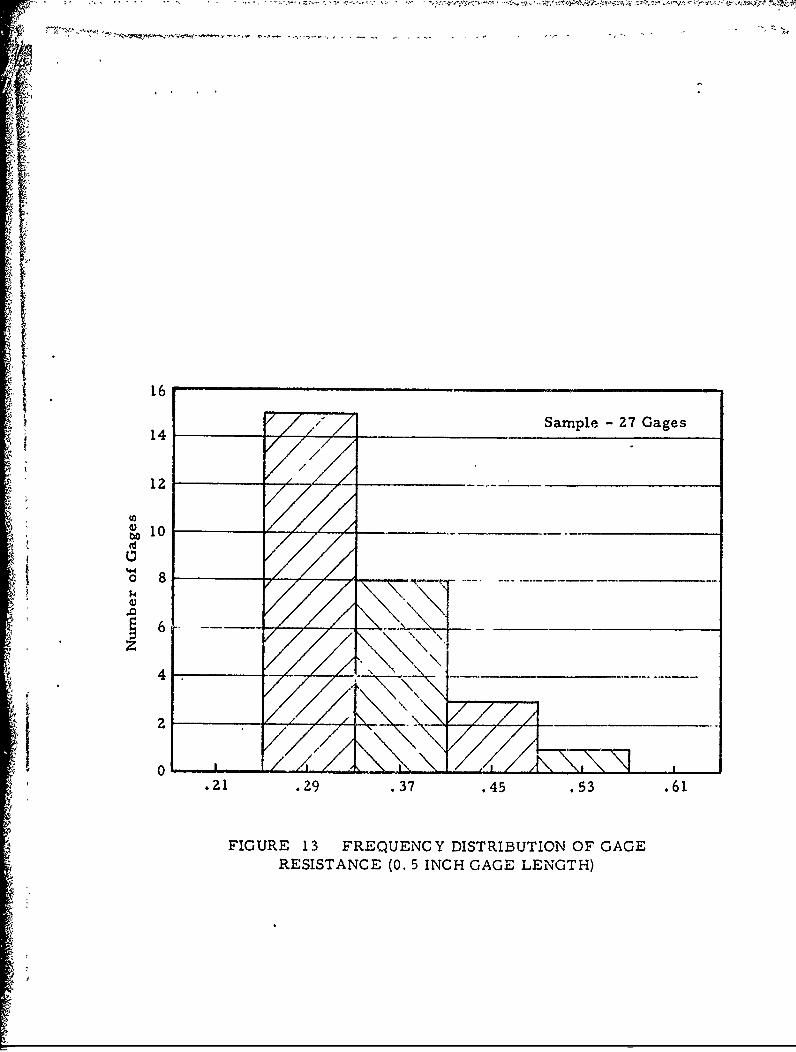
Both of these deficiencies have been corrected by improved fabri-
cation techniques. As illustrated in Figz-re 13, the nominal resistance
range of 27 gages is 0. 32 ohm (0. 57-0 25); however, 85 percent of the
gages are within a 0. 16 ohm range. Additional refinements in the design
and fabrication of the strain transdu(.er will yield a more uniform gage.
Eklngation. Upon the corrjletion of fabrication, each gage is
clamped in the extensiometer and elongated This procedure has two
purposes: (1) to serve as a proof test to insure the gages function over
the expected strain range, and (2) to establish the relationship of resis-
tance change versus gage elongation.
All new gages have shown a need for several "shakedown" elonga-
tion cycles before the elongation-resistance change has stabilized and a
repeatable curve is determined. These-cycles are performed in rapid
succession with the gage never remaining in the extended configuration
in excess of one minute to minimize the plastic deformation of the gage
body. However. the polyurethane gage body exhibits a near total creep
recovery when deformed for long time intervals and then released A
typical elongation-resistance change curve is si-own in Figure 10. The
relationship is nearly linear over the 50 per cent strain range with a
slight divergence from a constant slop(- within the initial 5 per cent strain
and the 45 to 50 per cent strain segments The slopes of 14 transducers
calibration cuives are compared in the frequency distribution graph
(Figure 14); the values vary from 0 70 to., 1 10 ohms per incl" of eloniuation
16i 14 Sample- 27 Gages
tolo
144 _ _
o 8
.21 .29 .37 .45 .53 .61
FIGURE 13 FREQUENCY DISTRIBUTION OF GAGERESISTANCE (0. 5 INCH GAGE LENGTH)

22
Sample -14 gages
43
. 6o .70 .-80 .g0 1.00 1. 10 1.20
Slope of Curves :ohms per inch of ,alongation)
FIGURE 14 FREQUENCY DISTRIBUTION OF SLOPES FORRESISTANCE VERSUS GAGE ELONGATION C URVES.

23
There appears to be no relationship between nominal resistance and the
gages' calibration curve slopes.
In the calibration procedure, a gage is strained to a certain level
I, of elongation; this is maintained constant until the next incremental de-
formation is applied. Being a viscoelastic material, the gage undergoes
a stress-relaxing process at each stage of loading. Nevertheless, the
resistance readings taken at several time intervals at each stage of
elongation are consistent and, therefore, there is apparently no change
in the gage length capillary geometry during stress relaxation. Converse-
ly, upon release of the elongated gage, the strain transducer does not
immediately return to ics initial (no-load) configuration because of resid-
ual stresses As the gage length capillary is responsive to most all body
strains, it is not surprising that a variation of gage resistance exists
while the body creeps to its initial geometrical configuration.
In an actual gage application, where the elastomeric strain trans-
d ducer is bonded t. a specimen's surface, a most important characteristic
is its suppleness in relation to th,. specimen; that is. the gage's body should
be a negligible reinforcing element when applied to the specimen's surface
thereby allowing the surface to displace in an unhindered fashion Accord-
ingly, the gage will " e forced to defot.- with the specimen surface on which
it is mounted; this type of deformation is neari! independent of the gage's
internal stresses. Co.,_equently, the phase uf the extensiometer calibra-
tion tests in which the gage is permitted to rettirn to its initial (no-loadi
i:
r': 24
42configaration has no counterpart in an actual gage application.
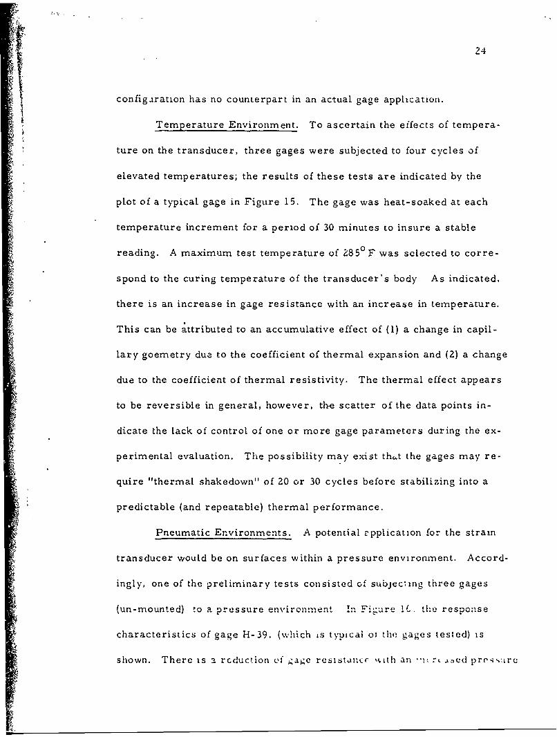
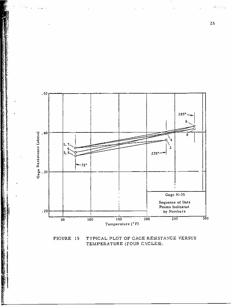
Temperature Environment. To ascertain the effects of tempera-
ture on the transducer, three gages were subjected to four cycles of
elevated temperatures; the results of these tests are indicated by the
plot of a typical gage in Figure 15. The gage was heat-soaked at each
temperature increment for a period of 30 minutes to insure a stable
reading. A maximum test temperature of 285 F was selected to corre-
spond to the curing temperature of the transducer's body As indicated.
there is an increase in gage resistance with an increase in temperature.
This can be attributed to an accumulative effect of (1) a change in capil-
lary goemetry due to the coefficient of thermal expansion and (2) a change
due to the coefficient of thermal resistivity. The thermal effect appears
to be reversible in general, however, the scatter of the data points in-
dicate the lack of control of one or more gage parameters during the ex-
perimental evaluation. The possibility may exist thct the gages may re-
quire "thermal shakedown" of 20 cr 30 cycles before stabilizing into a
predictable (and repeatable) thermal performance.
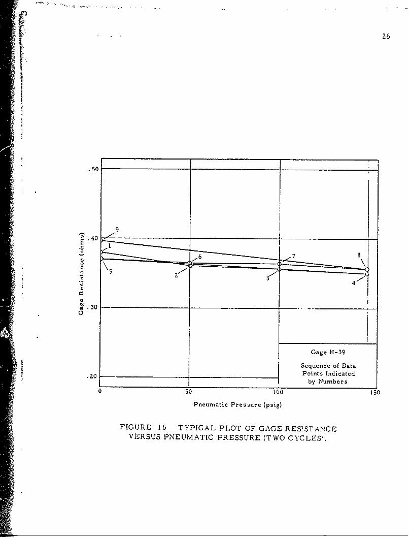
Pneumatic Environments. A potential -pplication for the strain
transducer would be on surfaces within a pressure environment. Accord-
ingly, one of the preliminary tests consisted of subjecting three gages
(un-mounted) to a pressure environment in Fi-gure 1C .the, response
characteristics of gage H-39. (which Ls typical oi the gages tested) is
shown. There is a rcduction of gage resistUcr %,.ith an ,i,,r:,( ted pref-•,irc
2 25
1 ~.50
44)
.300
30
IGage H-35
Sequence of DataPoints Indicated
.20 by Numbers
50 100 150 200 250 300Temperature C F)
FIGURE 15 TYPICAL PLOT OF GAGE RESISTANCE VERSUS
TEMPERATURE (FOUR CYCLES).
A,26
-* .50
U9
to.30
Gage H-39
Sequence of Data
-.0 _O ,Points Indicated
__by Numbers0 50 t00 150
Pneumatic Pressure (psig)
FIGURE 16 TYPICAL PLOT OF GAGE RESISTANCEVERSUS PNEUMATIC PRESSURE (TWO CYCLES%.

27
environment. As with the thermal evaluatiu., the pn.-,eT-atc environment
tests are not conclusive. It was determined that pressurization duration
was a critical factor as the gage body relaxed under the applied loading.
Readings were taken at each load increment until the gage resistance
stabilized. The data points shown in Figure 16 are terminal values gen-
erally measured after the pressure increment had been applied for a period
of ten minutes.
3i
t
K28
VI. F•UTURE WORK
The preliminary evaluation of the elastomeric strain transducers
has demonstrated the concept's feasibility and has indicated possible scope
of application. The gage was observed for performance characteristics
under environmental pakameters of temperature and pressure. Certain
fabrication techniques were examined in relations to the gage performance
and improved procedures incorporated where possible. However, several
aspects of the strain transducer design require further study and improve.
ment.
VGage Resistance. The nominal gage resistance (less than 1 ohm
for 0. 5 inch base length gage) is low in comparison to conventional elec-
trical resistant gages. In addition to requiring special readout equipment
and circuitry, the low resistance also adversely affects the strain trans-
ducer sensitivity. For transducer applications involving retrieval of
intelligence through a slip-ring circuit, the strain prototype's signal would
Sbe obscured in the background noise.
Two readily apparent and immediate approaches to increase the
gage resistance would be to (1) reduce the capillary cross-sectional area
and/or (2) to utilize a conducting fluid with a greater electrical resistanceBoth I and 3 mil diameter capillaries" hay, bee: explored -nd appear to
"!"The prototype transducer "A" and "H" ccn: - , . [l da,'-eter c•pi'.Li :c ..

29
be feasible from a fabrication stau.dpoint. Preliminary gage designs em-
ploying the 3 mil diameter capillary indicated a nonlinear relationship be-
tween elongation and resistance change; the 1 mil gage was erratic in per-
formance. Nevertheless, a greater nominal resistance was achieved in
both cases.
The selection of the conducting fluid is limited to those materials
which are compatible with the polyurethane gage body. Water and oil base
fluids react with polyurethane causing swelling in and around the capillary.
The presently used mercury base fluid is an inert compound and provides
a stable gage with a shelf life of several months. Although polyurethane
exhibits desirable elastic and creep recovery properties, there are other
material candidates which may suffice in these areas and be receptive to-• Ia broader range of conductive fluids. These candidates are being inves-
tigated.
Gage Rigidity. For elastomeric strain transducers, an important
characteristic is gage rigidity. Special care is required in matching
-f boundary conditions between the gage body and the surrounding medium.
especially for the embedded gage. The surface mounted gage rigidity re-
quirement is different from the embedded gage, in order to minimize a
local stress field distortion caused by -the reinforcing effect of the gage,
the gage body (and bond cement) must have a maximum flexibility. The
flexibility is a function of both gage dimensions (cross-sectional area of
gage body) and the body material modulus. The initial proJotype gage

'4 .30
* (Figures 4 and 1") represent a relatively rigid device which will be modi-
fied to a more supple instrument. The modification will take the form o.f
a reduced cross-sectional area for the gage body and the utilization of
gage materials with lower moduli. The effectiveness of these modifica-
tions will be determined as a function of force required to elongate (or
compress) a gage body through a specified displacement.
"* Temperature and Pressure Influence. The preliminary evalua-
tions indicate that both temperature and pressure excursions effect a
resistance change in the gages. The initial data was inconclusive as to
exact empirical relationships, however, certain trends were noted. It
is important that the study of these environmental parameters be con-
tinued in order that methods of controls may be developed. It is expected
that calibration procedures (similar to those in use with conventional foil
* gages) will be feasible.
Range of Ap.lication. One of the basic attributes of the elasto-
meric gage concept is its application for high elongation strains (up to
50 per cent). The confidence limits of the initial prototypes is t 2 per
cent strain which immediately restrict its scope of application to strain
ranges of 10 per cent or more. A refinement in this sensitivity is be-
lieved obtainable by increasing the gage resistance and improving the
fabrication techniques.
Other Parameters. The influence of several other parameters
on gage performance is presently unktnown. 1he inure nt1,rrt.nt of

1'' .. , , f31
these are (a) the effects of acceleration, (b) the limitation to frequency
response and (c) the stability of a transducer during tests of extended
duration and during a period of prolonged shelf life.
:1/
-
b
A