809 ' # '7& *#8 & 1 - intechcdn.intechopen.com/pdfs-wm/13395.pdf ·...
TRANSCRIPT

3,350+OPEN ACCESS BOOKS
108,000+INTERNATIONAL
AUTHORS AND EDITORS115+ MILLION
DOWNLOADS
BOOKSDELIVERED TO
151 COUNTRIES
AUTHORS AMONG
TOP 1%MOST CITED SCIENTIST
12.2%AUTHORS AND EDITORS
FROM TOP 500 UNIVERSITIES
Selection of our books indexed in theBook Citation Index in Web of Science™
Core Collection (BKCI)
Chapter from the book Aluminium Alloys , Theory and ApplicationsDownloaded from: http://www.intechopen.com/books/aluminium-alloys-theory-and-applications
PUBLISHED BY
World's largest Science,Technology & Medicine
Open Access book publisher
Interested in publishing with IntechOpen?Contact us at [email protected]

5
Non-Destructive Testing Techniques for Detecting Imperfections in
Friction Stir Welds of Aluminium Alloys
Pedro Vilaça1,2 and Telmo G. Santos3 1IDMEC, Instituto de Engenharia Mecânica, Av. Rovisco Pais, 1, 1049-001 Lisboa
2IST-UTL, Instituto Superior Técnico, Av. Rovisco Pais, 1049-001 Lisboa 3UNIDEMI, DEMI, Faculdade de Ciências e Tecnologia, UNL, 2829-516 Caparica
Portugal
1. Introduction
The invention of Friction Stir Welding (FSW) (Thomas, 2009) has contributed for a significant push forward in the weldability criteria for many engineering materials and the concept of how they can be mechanically processed in solid state. From the many materials processed by FSW the most remarkable results were obtained for the aluminium and all its alloys including wrought and cast original conditions. The main technological procedures and parameters are presented and most relevant tool features and architecture are established (Vilaça, 2003). Some industrial applications of FSWelds of aluminium alloys are also summarized. The quality of FSWelds of aluminium and its alloys is easy to reproduce and usually excellent, exceeding for some particular conditions the performance of base materials. Nevertheless, some imperfections can occur. The geometry, location, and microstructural nature of these imperfections will be established and classified for butt and overlap joints, which are the basic geometries enabling the production of all the remaining joint configurations, by combination of the previous. These imperfections bear no resemblance to the imperfections typically found in aluminium fusion welds. Consequently, it is difficult or even impossible, to identify all the FSWelds imperfections with commercially available conventional and advanced non-destructive testing (NDT) techniques. A paradigmatic example is the micro defects located at the root of conventional FSWeld joints with less than 100-50 µm. This state-of-the-art has been revealed as one important drawback preventing a wider transition of FSW to industrial applications, mainly focusing those where the quality standards are highly demanding and pursue the total quality assurance paradigm. The review of physical fundaments and some technological features of the different NDT concepts is included supporting the presentation of the following content of the present chapter (Santos, 2009). The assessment of the applicability of the conventional and advanced available NDT techniques to the most relevant FSW imperfections is established. The lack of assertiveness of the available NDT techniques in detecting the FSW joint imperfections are identified emphasizing the importance of the most recent new advances in the NDT technological
www.intechopen.com

Aluminium Alloys, Theory and Applications
94
field, regarding the support of the industrial production of FSWelds involving aluminium and aluminium alloys. To solve this lack of technological capacity in detecting non-destructively some imperfections in FSWelds, which may significantly affect the performance of the weld joints, many research and technological development projects are being undertaken and some of the most relevant results are presented in this chapter. The presentation of these new developments starts with the presentation of a system with acronym: QNDT_FSW, which consist of an integrated, on-line, NDT inspection system for FS welds, which employs a data fusion algorithm with fuzzy logic and fuzzy inference functions. It works by analyzing complementary and redundant data acquired from several NDT techniques (ultrasonic, Time of Flight Diffraction (ToFD), and eddy currents) to generate a synergistic effect that is used by the software to improve the confidence of detecting imperfections. The next NDT development presented is a innovative system consisting of a new patented eddy current (EC) probes; electronic generation, conditioning and signal acquisition; automated mechanized scanning and dedicated NDT software. The new EC probe allows a 3D induced current in the material, and an easy interpretation of the signal based, not on the absolute value, but on a comprehensible perturbation of the signal. The results from an analytical simulation fully agree with the experiments.The experimental results clearly show that this system is able to detect imperfections around 50 µm, which contribute to increase the reliability on NDT of micro imperfections.
2. FSW process fundaments
2.1 General features Friction stir welding (FSW) is a process for joining workpieces in the solid-phase, using an intermediate non-consumable tool, with a somewhat complex shoulder and probe profile, made of material that is harder than the workpiece material being welded. FSW can be regarded as an autogenous keyhole joining technique without the creation of liquid metal (Thomas et al., 1991). The rotating tool, is plunged into the weld joint and forced to traverse along the joint line, heating the abutting components by interfacial and internal friction, thus producing a weld joint by extruding, forging and stirring the materials from the workpieces in the vicinity of the tool. The basic principles of the process and some nomenclature are represented in Figure 1. This machine tool based process is recurrently considered the most important recent development in the welding technology, saving costs and weight for a steadily expanding range of applications of Lightweight Metallic Structures. As evidence of the disruptive character of the FSW process, world-wide research and development centers have chosen this issue has as a primary priority and the many significant advantages of FSW have rapidly been transferred to industry. Initially to the most demanding quality standards industrial applications and more recently spread to a wide range of structural and non-structural components.
2.2 Parameters One important advantage of FSW is the Total Quality Assurance of results once all the process parameters are correctly established and monitored during the processing. The process parameters are easy to assess because FSW is mostly a mechanical welding process
www.intechopen.com

Non-Destructive Testing Techniques for Detecting Imperfections in Friction Stir Welds of Aluminium Alloys
95
Fig. 1. Representation of some of the main parameters and nomenclature of FSW joints
where the results do not depend on difficult to control conditions, such as, environmental conditions or operator skills. For achieving the Total Quality Assurance conditions, one important requirement is a strong, stiff machine and clamping system, able to react and apply the necessary load onto the workpiece via the tool, allowing to create and maintain the correct conditions. In order to optimize the performance of the resultant FSW joint, and considering that the FSW results can be sensitive to variations of some welding parameters, it is important to identify and understand possible interactions between the welding parameters. The main FSW process parameters are the following: 1. FSW tool geometry; 2. Travel speed, v [mm/min];
3. Rotation speed, Ω [rpm]; 4. Rotation direction [CW or CCW]; 5. Tool rotational axis eccentricity [mm]; 6. Vertical downward forging force, Fz [N]; 7. Plunge distance of probe bottom to anvil [mm]; 8. Plunge speed, [mm/s]; 9. Dwell time, [s];
10. Tilt angle, α [º];
11. Concordance angle, θ [º];
www.intechopen.com
Aluminium Alloys, Theory and Applications
96
12. Start position, (x,y) [mm]; 13. End position, (x,y) [mm]; 14. FSW control mode during weld [Force/Position]; 15. Initial temperature/interpass temperature of welded components.
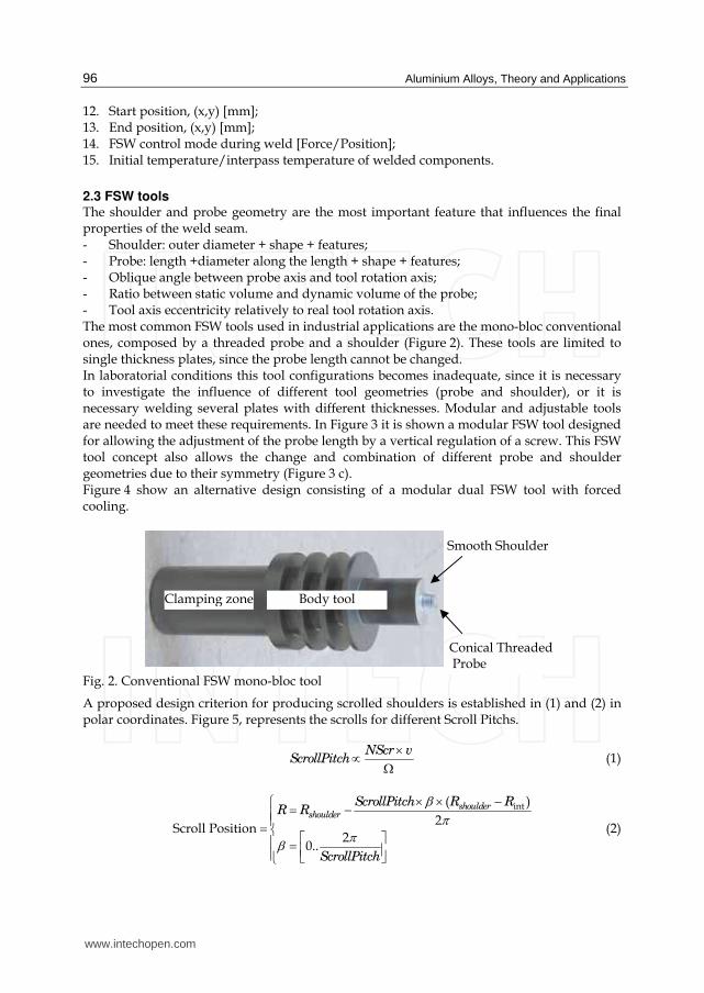
2.3 FSW tools The shoulder and probe geometry are the most important feature that influences the final properties of the weld seam. - Shoulder: outer diameter + shape + features; - Probe: length +diameter along the length + shape + features; - Oblique angle between probe axis and tool rotation axis; - Ratio between static volume and dynamic volume of the probe; - Tool axis eccentricity relatively to real tool rotation axis. The most common FSW tools used in industrial applications are the mono-bloc conventional ones, composed by a threaded probe and a shoulder (Figure 2). These tools are limited to single thickness plates, since the probe length cannot be changed. In laboratorial conditions this tool configurations becomes inadequate, since it is necessary to investigate the influence of different tool geometries (probe and shoulder), or it is necessary welding several plates with different thicknesses. Modular and adjustable tools are needed to meet these requirements. In Figure 3 it is shown a modular FSW tool designed for allowing the adjustment of the probe length by a vertical regulation of a screw. This FSW tool concept also allows the change and combination of different probe and shoulder geometries due to their symmetry (Figure 3 c). Figure 4 show an alternative design consisting of a modular dual FSW tool with forced cooling.
Fig. 2. Conventional FSW mono-bloc tool
A proposed design criterion for producing scrolled shoulders is established in (1) and (2) in polar coordinates. Figure 5, represents the scrolls for different Scroll Pitchs.
NScr v
ScrollPitch×∝ Ω (1)
int( )
2Scroll Position
20..
shouldershoulder
ScrollPitch R RR R
ScrollPitch
βππβ
× × −⎧ = −⎪⎪= ⎨ ⎡ ⎤⎪ = ⎢ ⎥⎪ ⎣ ⎦⎩ (2)
Clamping zone Body tool
Smooth Shoulder
Conical Threaded Probe
www.intechopen.com

Non-Destructive Testing Techniques for Detecting Imperfections in Friction Stir Welds of Aluminium Alloys
97
Where: NScr – Number (integer) of scrolls (this value is set to a maximum of NScr=4); Rshoulder – Exterior radius of the shoulder [mm]; Rint – Interior radius of the shoulder [mm]; β – Angle starting with the scroll on the exterior diameter of the shoulder and ending where the scroll ends at the interior radius of the shoulder [rad].
(a) (b)
(c)
Fig. 3. Modular dual FSW tool. a) 3D view of assembly, b) Cutaway view in two perpendicular planes, c) Detail of geometric duality of the dual basis and probe dual. Nomenclature: main body (1), dual shoulder (2), dual-probe (3), vertical adjustment screw (4), bolts of the dual basis (5), dual screw probe (6).
www.intechopen.com

Aluminium Alloys, Theory and Applications
98
(a) (b)
(c)
Fig. 4. Modular dual FSW tool with forced cooling. a) 3D view of assembly, b) Viewed in longitudinal section, c) Viewed in cross section showing in detail the mechanism for adjusting the length of the probe. Nomenclature: tool body (1), built-in base (2), adjustable threaded probe with 1 mm pitch (3) screws to fix the base (4), threaded bolt fastening probe (5).
0.5ScrollPitch= 1ScrollPitch= 2ScrollPitch=
Fig. 5. Graphical representation of planar shoulders with 2 scrolls (spiral striates) for different ScrollPitch = {0.5; 1; 2}. Constant Values: Number of scrolls (striates)=2; Rext=20
mm; Rint=5 mm; Ω=800 rpm.
www.intechopen.com

Non-Destructive Testing Techniques for Detecting Imperfections in Friction Stir Welds of Aluminium Alloys
99
2.4 Typical metallurgical features During the FSW process, the material undergoes intense plastic deformation at elevated temperature, resulting in generation of fine and equiaxed recrystallized grains. This fine microstructure produces good mechanical properties in friction stir welds (Moreira et al., 2009). Better quality joints are associated with more intense tridimensional material flow pattern. The typical metallurgical structures present in the processed zone of FS welds are established and classified in Figure 6. Beside the TMAZ central zone, there is the Heat affected Zone (HAZ) and the unaffected parent material or Base Material (BM)
Fig. 6. Generic identification of micrograph locations
The composition of the recrystallised zone of the TMAZ (the nugget) is unchanged from that of the parent material and there is no measurable segregation of alloying elements but grain size varies across the flow contours. Joining does not involve any use of a filler metal and therefore any lightweight metal and alloy can be joined without concern for the compatibility of the composition, which would be an issue in fusion welding. When desirable, dissimilar lightweight metal alloys and metal matrix composites can be joined with equal ease. The principal advantages of FSW, being a solid phase process, are low distortion, absence of melt-related imperfections and high joint strength, even in those alloys that are considered non-weldable by conventional fusion techniques. Furthermore, FSW joints are characterised by the absence of filler induced problems/imperfections. In addition, the hydrogen contents of FSW joints tend to be low, which is important in welding alloys susceptible to hydrogen damage.
3. Production and characterization of FSW samples with and without defects
3.1 Base material, FSW tools and equipment The materials under study were AA2024-T4 and AA5083-H111 alloys, with 3.8 and 7.0 mm thickness respectively, having the chemical composition presented in Table 1. In Figure 7 it is shown the macrographs of AA2024-T4 in three different views: perpendicular and parallel to the rolling direction, and at surface of the plates. A conventional milling machine (Figure 8a) and an ESAB LEGIOTM FSW 3UL (Figure 8b) were used to produce FSW in AA5083-H111 and in AA2024-T4, respectively. Several FSW tools geometry was tested to produce different welded conditions with and without defects. Table 3 describes the characteristics of three different FSW shoulders, and Table 4 describes the eight FSW tools tested. These tools are illustrated in Figure 9.
www.intechopen.com

Aluminium Alloys, Theory and Applications
100
Material Al Cr Cu Fe Mg Mn Si Ti Zn
AA5083-H111 94.5 0.08 0.03 0.33 4.39 0.51 0.12 0.02 0.01
AA2024-T4 93.5 max. 0.1
3.8 – 4.9max. 0.5
1.2 – 1.8 0.3 – 0.9max. 0.5
max. 0.15
max. 0.25
Table 2. Chemical composition of base materials as % of weight
(a) (b) (c)
Fig. 7. Macrographs of AA2024-T4 perpendicular (a) and parallel (b) to the rolling direction, and in surface of the plates (c).
(a) (b)
Fig. 8. FSW equipments used to produce FSW samples. a) Conventional milling machine and the ESAB LEGIOTM FSW 3UL.
Base Øexterior [mm] Øinterior [mm] Tipo
A 15 5 Non-scrolled concave
B 19 8 Planar with spiral scrolls.and p = 2
C 18 6 Planar with spiral scrolls.and p = 0.5
Table 3. Characteristics of the FSW shoulders
www.intechopen.com

Non-Destructive Testing Techniques for Detecting Imperfections in Friction Stir Welds of Aluminium Alloys
101
Tool Base Probe
# 1 A cylindrical M5 with 3 flat sided
# 2 B conical threaded M8 with 3 helicoidal longitudinal channels (Øbase = 8 mm, Øtop = 5 mm)
# 3 B stepped smooth surface (Øbase = 8 mm, Øtop = 6 mm)
# 4 B conical smooth surface (Øbase = 8 mm, Øtop = 5 mm)
# 5 B cylindrical smooth surface, with 4 helicoidally groves at the tip (Øbase = 8 mm, Øtop = 6 mm)
# 6 A inverted conical smooth surface (Ø middle = 4 mm, Øtop = 5 mm)
# 7 A conical smooth surface, with 1 helicoidally groves at the tip (Øbase = 8 mm, Øtop = 4 mm)
# 8 C conical threaded with 3 flat sided (Øbase = 6 mm, Øtop = 5 mm)
Table 4. Characteristics of the FSW tools (shoulders + probes)
Tool # 1 Tool # 2 Tool # 3 Tool # 4
Tool # 5 Tool # 6 Tool # 7 Tool # 8
Fig. 9. FSW tools used to produce defect and non defect condition on AA2024-T4 and AA5083-H111
3.2 Production and characterization of FSW samples To test and validate the NDT developed systems, some friction stir welds were produced using the above mentioned aluminium alloys AA2024-T4 and AA5083-H111. FSW with high defects conditions were initially produced on AA5083-H111, as it shows by transverse macrograph in Figure 10. The non defect condition (Figure 10 a) correspond to a bead on plate weld, and was produced using the FSW tool #1. The high void defect condition (Figure 10 b) also corresponds to a bead on plate weld produced with the FSW
www.intechopen.com

Aluminium Alloys, Theory and Applications
102
tool #1. The high void and root defect condition (Figure 10 c) was produced using the FSW tool #6. The propose of this welded conditions was to evaluate the applicability of different existent NDT techniques on FSW. This issue will be addressed in section § 4. In addition, this welded conditions was used to calibrate the Quantitative Non Destructive Testing System for FSW (QNDT_FSW) described in § 5.1, in order to compare and classify others FSW with these standard defect conditions.
(a) (b) (c)
Fig. 10. FSW produced on AA5083-H111. a) Non defect condition (bead on plate), b) High void defect condition, c) High void and root defect condition
The AA2024-T4 alloy was used to produce three different root defect conditions: Type 0, Type I and Type II (Figure 11). Defect Type 0 is characterized by some residual particles alignment in an intermittent path along ~ 150 μm. This condition is considered a non defective weld. Defect Type I is characterized by a weak or intermittent welding since the materials are in close contact, under severe plastic deformation, but with no chemical or mechanical bond along ~ 50 μm. Defect Type II is characterized by ~ 200 μm non welded zone, followed by particles alignment in an intermittent path. The three different conditions present a consecutive increase of the defect intensity, suitable for a reliability analysis of a NDT system.
Fig. 11. Transversal macrographs of three different FSW root defects conditions on AA2024-T4 using tool # 2. Defect Type 0: particles alignment, Defect Type I: ≈ 60 μm, Defect Type II: ≈ 200 μm
Other different defects morphology was produced in AA2024-T4 alloy, exploring other FSW
tools, in order to correlate the tools geometry and the weld quality of the joints. Figure 12
presents four transversal macrographs of different weld defects conditions produced with
different FSW tools. Defect Type III (Figure 12 a) is an internal imperfection type void.
Figures 12 a), b) and c) presents a mixed defect weld condition consisting of a root and void
defects. These analyses allow concluding that the geometry of the FSW tool #2 produces the
best quality welded joints.
www.intechopen.com

Non-Destructive Testing Techniques for Detecting Imperfections in Friction Stir Welds of Aluminium Alloys
103
(a) (b)
(c) (d)
Fig. 12. Macrographs of four different FSW void and root defects conditions on AA2024-T4 a) FSW with defect Type III using tool # 2), b) FSW with defect Type M using tool # 4), c) FSW with defect Type M using tool # 6), d) FSW with defect Type M using tool # 7).
3.3 Effects of defects Fatigue tests were performed on AA2024-T4 in order to evaluate the effects of defects on mechanical behavior of the welded joints. The propose was to identify witch defect condition (Type 0, Type I, Type II and Type III) presents a significantly decrease of fatigue life comparing to the base material. The fatigue tests are performed on an Instron 8874, with a load cell of 25kN. Stress ratio R is 0.1. The S-N curve results obtained are presented in Figure 13 (Santos et al., 2009). This result leads to conclude about the good mechanical efficiency of the FSW joints with Defect Type 0. In fact, these joints present a mechanical behaviour similar to the base material. Concerning to the other three defect types, all presents a significantly loss of mechanical resistance. Among these different defects, the root defects (Type II) are definitely the ones that show higher loss of mechanical properties under fatigue loading. Those imperfections are thereby the NDT targets defects of FSW. Furthermore, the other type of imperfections (e.g. thickness reduction and flash formation) may be inherent to the process itself and are impossible to be avoided or may be evaluated without need of NDT.
4. Evaluation of the applicability of conventional NDT techniques to FSW
In order to evaluate the applicability of conventional NDT techniques to FSW some experimental tests were performed on above described defects conditions on AA2024 – T4
www.intechopen.com

Aluminium Alloys, Theory and Applications
104
Fig. 13. Fatigue curves for base material and 4 different defect type conditions
and AA5083-H111. The propose is to conclude about the capability of conventional NDT techniques to detect the FSW defects with the morphologies described in section § 3.2.
4.1 Conventional X-ray The specimens were analyzed using conventional X-Rays, in Scan-Ray® equipment, DOA
300/AC-103 model, rightly calibrated and certificated. AGFA® D4 X-Ray film, an extra fine
grain film with very high contrast, and with density value of 2 was used for these trials.
The X-ray parameters were: Intensity: 5mA; Energy: 70 kV; Exposure time: 150 sec; Distance
between the source and the film: 800 mm.
The friction stir welds were oriented with the root to the X-ray film in order to avoid image
distortion in the cases that the defect at the root was detected. The quality image control and
the acquirement of the sensitivity values were done with a pattern behind the sample, in
accordance of the standard DIN 54109 and recommended by the International Institute of
Welding.
In Figure 14 it is present the X-ray image of specimens produced on AA5083-H111 with high
defects type voids and roots similar to the ones presented in Figure 10 a and Figure 10 b). It
is possible to observe that booth root and internal defects are visible, since they are very big.
However, X-ray NDT technique cannot detect FSW micro root defects whit the morphology
described in Figure 11. In Figure 15 and Figure 16 it is presented X-ray image of specimens
produced on AA2024-T44 with root defect Type II and void defect Type III, respectively.
The acquired image (Figure 15) show that even the biggest root defect (Type II) was not
detected. Only defect Type III (void defect) was detected, as it shows in Figure 15.
www.intechopen.com

Non-Destructive Testing Techniques for Detecting Imperfections in Friction Stir Welds of Aluminium Alloys
105
Fig. 14. X-ray image of specimens produced on AA5083-H111 with high voids and roots defects
Fig. 15. X-ray image of specimens produced on AA2024-T4 with roots defects Type II
Fig. 16. X-ray image of specimens produced on AA2024-T4 with void defects Type III
4.2 Conventional creping ultra-sound Creeping ultrasonic inspection was performed with a 4 MHz probe, on both retreating and advancing sides of the weld, where the insonification direction was always perpendicular to the welding direction (Figure 17). Gathering data from both sides of the weld created a redundancy of data, which was analyzed by the data fusion algorithm of the QNDT_FSW described in § 5.1. Creeping inspection was also complemented with data that came from
www.intechopen.com

Aluminium Alloys, Theory and Applications
106
attenuation measurements. The measurement of the attenuation is performed with an ultrasonic probe working in receiving mode, located at the opposite side of the weld bead in the same insonification plane of the creeping probe. Therefore, in the case of defect, a creeping signal change occurs, increasing at the same time the attenuation. These two simultaneous conditions allowed the QNDT_FSW system to distinguish between signal disturbance and real imperfections. The results of the NDT creeping ultra-sound on AA5083-H111 presented in Figure 18 show that the high root defects was detected by a signal change, underline by the red boxes. However, once again, the micro root defects presented in AA2024-T4 was not detected.
a) b)
Fig. 17. Inspection of FSW with conventional creping ultra-sound. a) Creeping and attenuation probes displacement, b) Schematic representation of the ultra-sound waves in the material AA6083-H111.
a) b) c)
Fig. 18. Results of the NDT creeping ultra-sound on AA5083-H111. a) Non defect condition (bead on plate) of Figure 10 a, b) Moderate FSW root defect condition, c) High void and root defect condition of Figure 10 c.
4.3 Time of Flight Diffraction (ToFD) Time of Flight Diffraction (ToFD) NDT technique was performed with a 15 MHz probes on the same samples described in above section § 4.2. Figure 19 shows the used arrangement of the probes and the motion device. Once again, the results presented in Figure 20 shown that ToFD technique was able to identify high root and void defects in AA5083-H11 samples, by a evident signal change underline by the red boxes. Nevertheless, the micro root defects presented in AA2024-T4 was not detected.
www.intechopen.com

Non-Destructive Testing Techniques for Detecting Imperfections in Friction Stir Welds of Aluminium Alloys
107
a) b)
Fig. 19. ToFD ultra-sound NDT testing of AA5083-H111. a) 15 MHz ToFd probes used, b) Arrangement of the probes and motion device.
a) b) c)
Fig. 20. Results of the NDT ToFD ultra-sound on AA5083-H111. a) Non defect condition (bead on plate) of Figure 10 a, b) Moderate FSW root defect condition, c) High void and root defect condition of Figure 10 c.
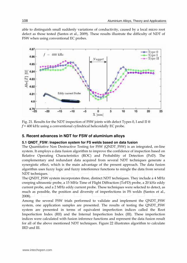
4.3 Conventional Eddy Current (EC) The three FSW defect conditions Type 0, Type I and Type II in AA2024-T4, described in
Figure 11 (section § 3.2) were inspected by NDT eddy current (EC) technique using a
conventional cylindrical helicoidally EC probe.
The signal was acquired from the root side, along a sweep on the transversal direction to the
weld joint. The starting point of the tests was set to 25 mm in the retreating side of the weld
bead, and 50 mm long segments were characterized in direction to the advancing side, with
250 μm space within each acquisition. In all the acquisitions the real and imaginary part of
electrical impedance was measured @ f = 400 kHz.
In Figure 21 it is presented the obtained results S(x) = Abs{Z}. It can be seen that the three
curves concerning to the previously defects conditions present a very similar trend between
them.
It means that the conventional probes have very low sensitivity to root defects. The reason is
that the impedance changes are mainly due to the presence of the FSW weld bead, instead
the presence of a defect. In fact the FSW process causes microstructural modifications
(Nascimento et al., 2009) material conductivity changes in the bead zone, even without any
imperfections. Therefore there is no distinctive signal feature that can allow to distinct
between each defect condition. Indeed, the absolute conventional probe can only reproduce
the global spreaded increase of conductivity field due to the FSW bead. Such probes are not
www.intechopen.com
Aluminium Alloys, Theory and Applications
108
able to distinguish small suddenly variations of conductivity, caused by a local micro root
defect as those tested (Santos et al., 2009). These results illustrate the difficulty of NDT of
FSW when using conventional EC probes.
Fig. 21. Results for the NDT inspection of FSW joints with defect Types 0, I and II @ f = 400 kHz using a conventional cylindrical helicoidally EC probe.
5. Recent advances in NDT for FSW of aluminium alloys
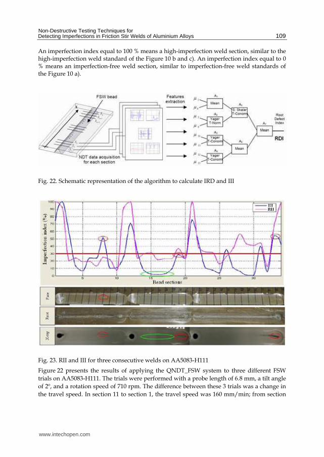
5.1 QNDT_FSW: Inspection system for FS welds based on data fusion The Quantitative Non Destructive Testing for FSW (QNDT_FSW) is an integrated, on-line
system. It employs a data fusion algorithm to improve the confidence of inspection based on
Relative Operating Characteristics (ROC) and Probability of Detection (PoD). The
complementary and redundant data acquired from several NDT techniques generate a
synergistic effect, which is the main advantage of the present approach. The data fusion
algorithm uses fuzzy logic and fuzzy interference functions to mingle the data from several
NDT techniques.
The QNDT_FSW system incorporates three, distinct NDT techniques. They include a 4 MHz
creeping ultrasonic probe, a 15 MHz Time of Flight Diffraction (ToFD) probe, a 20 kHz eddy
current probe, and a 2 MHz eddy current probe. These techniques were selected to detect, as
much as possible, the position and diversity of imperfections in FS welds (Santos et al.,
2008).
Among the several FSW trials performed to validate and implement the QNDT_FSW
system, one application samples are presented. The results of testing the QNDT_FSW
system are presented in terms of equivalent imperfection indices called the Root
Imperfection Index (RII) and the Internal Imperfection Index (III). These imperfection
indices were calculated with fusion inference functions and represent the data fusion result
for all of the above mentioned NDT techniques. Figure 22 illustrates algorithm to calculate
IRD and III.
www.intechopen.com
Non-Destructive Testing Techniques for Detecting Imperfections in Friction Stir Welds of Aluminium Alloys
109
An imperfection index equal to 100 % means a high-imperfection weld section, similar to the high-imperfection weld standard of the Figure 10 b and c). An imperfection index equal to 0 % means an imperfection-free weld section, similar to imperfection-free weld standards of the Figure 10 a).
Fig. 22. Schematic representation of the algorithm to calculate IRD and III
Fig. 23. RII and III for three consecutive welds on AA5083-H111
Figure 22 presents the results of applying the QNDT_FSW system to three different FSW
trials on AA5083-H111. The trials were performed with a probe length of 6.8 mm, a tilt angle
of 2º, and a rotation speed of 710 rpm. The difference between these 3 trials was a change in
the travel speed. In section 11 to section 1, the travel speed was 160 mm/min; from section
www.intechopen.com
Aluminium Alloys, Theory and Applications
110
21 to section 12, the travel speed was 224 mm/min; and from section 34 to section 22, the
travel speed was 320 mm/min. Based on a comparison (Figure 23) of the RII and III results
with the macroscopic, visual, and radiographic test results, the following conclusions were
made:
- The exit holes located at sections 1, 12 and 22 were detected by both imperfection
indices;
- In section 8, the III revealed a cavity, which was corroborated by radiographic testing
and visual inspection as the cavity breaks the surface of the workpiece. Moreover, the
RII was not affected, which confirmed the independence of both imperfection indices;
- Sections 14 to 18 present a very low III, which was corroborated by radiographic
testing. RII was able to detect small, root imperfections, as confirmed by metallographic
cross-sections of the weld. Emphasis should be given to the fact that in these sections,
radiographic testing cannot detect a root imperfection;
- For the 3 FSW trials, the RII increased as the travel speed increased. This behaviour was
expected because the probe length was 0.2 mm shorter than the plate thickness. This
created a small root imperfection that increased with increased in size as the travel
speed increased.
The proposed equivalent defect indices for evaluating the significance of root (RII) and
internal (III) imperfections show that the results accurately predicted the quality of the weld.
In fact, combining the data from several NDT processes is an improvement, when compared
to interpreting the individual results of each NDT process, due to the synergistic effect of the
data fusion algorithm.
5.2 Eddy current IOnic probe In order to improve the reliability in FSW non-destructive inspection a new NDT EC system
with a special designed probe was developed and tested in AA2024-T4 FSW defects
conditions. The EC probe allows a 3D induced eddy currents in the material; deeper
penetration; independence of the deviation between the probe and the material surface; and
easy interpretation of the output signal based on a comprehensible qualitative change.
The so called IOnic (Rosado et al., 2010) probe is constituted by one excitation filament, in
the middle of two sensitive planar coils, in a symmetric configuration (Figure 24). Due to
this layout the operation of the IOnic probe is based on an integration effect along each
sensitive coil, and simultaneous, on a differential effect between the two coils. The probe
was manufactured on 1.6 mm dual layer FR4 PCB subtract with an external diameter of
11 mm. The two sensitive coils are formed by tracks of 100 μm width separated by same
dimension gaps.
The IOnic probe has some other advantages when compared to the conventional eddy
currents probes: i) precision differential based operation resulting on high sensibility and
superior lift-off immunity; ii) improved contact with test material by being planar, leading
to deeper eddy currents penetration in test material; iii) the straight eddy currents induced
in the material near the driver trace can be taken as advantage to evaluate materials where
the flaws tend to follow a specific orientation; iv) allow the inspection of the material
borders as long as the symmetry axis remains perpendicular to it; v) can be implemented in
flexible substrates easily adaptable to non-planar and complex geometry surfaces.
www.intechopen.com

Non-Destructive Testing Techniques for Detecting Imperfections in Friction Stir Welds of Aluminium Alloys
111
The eddy current NDT System for FSW includes further dedicated components, namely: i)
electronic devices for signal generation, conditioning and conversion, ii) automated
mechanized scanning, and iv) dedicated software, shown in Figure 25.
The IOnic Probe was applied on AA2024-T4 defects condition Type 0, Type I and Type III described before in Figure 10. The data S(x) = Im{Ūout/Ī} was acquired from the root side, along a sweep on the transversal direction to the weld joint, with the excitation filament of the probe parallel to weld joint. The inspection was perform @ f = 50 kHz, f = 100 kHz and f = 250 kHz. The imaginary part of the three types of defects at these frequencies is shown in Figure 26.
Fig. 24. The IOnic Probe prototype.
Fig. 25. NDT system overview: laboratory apparatus for inspecting FS welds: the mechanical support system device and the computational data acquisition device.
www.intechopen.com

Aluminium Alloys, Theory and Applications
112
As FSW process causes material conductivity changes, even without imperfections, the weld bead is responsible for the large curve on the imaginary part. The presence of imperfections creates a small perturbation observed on the middle of the joint, highlighted in red. This small perturbation observed at the middle of the joint concerns to the suddenly decrease of conductivity due to the local root defect of each defect condition. Notice that there is a very good proportionality between the defect dimension and the observed perturbation on the imaginary part Im{Ūout/Ī}. These results show that IOnic probe is able to identify the three different types of defect conditions produced in AA2024-T4 aluminum alloy.
Fig. 26. Results of IOnic Probe for the FSW joints with defect types 0, I and II @ f = 50 kHz, f = 100 kHz and f = 250 kHz.
6. Conclusion
From the present work the following conclusions can be drawn:
Micro root defects in friction stir welds as the lack of penetration or kissing bond are defects
endorsed by failures in the process parameters that can occur in industrial applications.
These defects weaken the structural fatigue strength that in critical structural are not
tolerated. In this way, effective and reliable nondestructive techniques are required for the
detection of these flaws.
The geometry, location and microstructural nature of the FSW defects, which bore no
resemblance with defects typical of fusion welding of aluminium alloys, lead to very
difficulties in identification when using the common NDT techniques.
www.intechopen.com

Non-Destructive Testing Techniques for Detecting Imperfections in Friction Stir Welds of Aluminium Alloys
113
Conventional NDT techniques such as creeping ultrasound, ToFD, X-ray or axis-symmetry eddy current probes are not able to detect the typical FSW micro root defects with depth below 200 μm. A NDT integrated data fusion system for FSW named QNDT_FSW was presented.
Equivalent defective indexes are proposed for evaluating the relevance of the root (RDI) and
internal (IDI) defects. The data fusion algorithm for NDT of FSW, based on fuzzy logic and
fuzzy inference functions disclosed a general powerful data fusion NDT approach.
Combining the data from several NDT processes is an improvement, when compared to
interpreting the individual results of each NDT process, due to the synergistic effect of the
data fusion algorithm.
The experiments shown that the IOnic Probe is able to identify different levels of FSW micro root defects by a qualitative perturbation of the output signal. It was also shown that exist a good proportionality between the defects size and this signal perturbation.
7. Acknowledgements
The authors would like to acknowledge Fundação para Ciência e Tecnologia (FCT) for its financial support via project POCTI/EME/60990/2004
8. References
Moreira, P. M. G. P., T. Santos, S. M. O. Tavares, V. Richter – Trummer, P. Vilaça, P. M. S. T.
de Castro, (2009), Mechanical and metallurgical characterization of friction stir
welding joints of AA6061 – T6 with AA6082 – T6, Materials and Design
(ISSN: 0261-3069); Vol. 30, Issue 1, pp.180 – 187;
Nascimento, F., T. Santos, P. Vilaça, R.M. Miranda, L. Quintino, (2009), Microstructural
modification and ductility enhancement of surfaces modified by FSP in aluminium
alloys. International Journal of Materials Science and Engineering: A (Structural
Materials: Properties, Microstructure and Processing). Vol. 506, N.º 1 – 2, pp. 16 –
22,. DOI:10.1016/j.msea.2009.01.008.
Rosado, Luís, Telmo G. Santos, Moisés Piedade, Pedro Ramos, Pedro Vilaça, (2010)
Advanced technique for non-destructive testing of friction stir welding of metals,
Measurement (ISSN: 0263-2241); doi:10.1016/j.physletb.2003.10.071
Santos, T., P. Vilaça, L. Quintino, (2008), Developments in NDT for Detecting Imperfections
in Friction Stir Welds in Aluminium Alloys. Welding in the World (ISSN 0043 –
2288), Journal of the International Institute of Welding (IIW), Vol. 52, N.º 9 – 10,
pp.30 – 37;
Santos, Telmo, Pedro Vilaça, Luísa Quintino, (2009), Computational Tools For Modeling
FSW and An Improved Tool for NDT, Welding in the World (ISSN: 0043 – 2288),
Journal of the International Institute of Welding (IIW), (IIW-1978-08 (ex-doc. III-
1507r1-08), Vol. 53, N.º 5/6;
Thomas W M, Nicholas E D, Needham J C, Murch M G, Temple-Smith P, and Dawes C J
(1991) Improvements relating to friction stir welding. US Patent No. 5,460,317.
Thomas Wayne M. (2009). PhD thesis: An Investigation and Study into Friction stir Welding of
Ferrous-Based Material, University of Bolton.
www.intechopen.com

Aluminium Alloys, Theory and Applications
114
Vilaça, P, (2003). PhD thesis: Fundamentos do Processo de Soldadura por Fricção Linear -
Análise Experimental e Modelação Analítica, Instituto Superior Técnico, Technical
University of Lisbon.
www.intechopen.com

Aluminium Alloys, Theory and ApplicationsEdited by Prof. Tibor Kvackaj
ISBN 978-953-307-244-9Hard cover, 400 pagesPublisher InTechPublished online 04, February, 2011Published in print edition February, 2011
InTech EuropeUniversity Campus STeP Ri Slavka Krautzeka 83/A 51000 Rijeka, Croatia Phone: +385 (51) 770 447 Fax: +385 (51) 686 166www.intechopen.com
InTech ChinaUnit 405, Office Block, Hotel Equatorial Shanghai No.65, Yan An Road (West), Shanghai, 200040, China
Phone: +86-21-62489820 Fax: +86-21-62489821
The present book enhances in detail the scope and objective of various developmental activities of thealuminium alloys. A lot of research on aluminium alloys has been performed. Currently, the research effortsare connected to the relatively new methods and processes. We hope that people new to the aluminium alloysinvestigation will find this book to be of assistance for the industry and university fields enabling them to keepup-to-date with the latest developments in aluminium alloys research.
How to referenceIn order to correctly reference this scholarly work, feel free to copy and paste the following:
Pedro Vilaça and Telmo G. Santos (2011). Non-Destructive Testing Techniques for Detecting Imperfections inFriction Stir Welds of Aluminium Alloys, Aluminium Alloys, Theory and Applications, Prof. Tibor Kvackaj (Ed.),ISBN: 978-953-307-244-9, InTech, Available from: http://www.intechopen.com/books/aluminium-alloys-theory-and-applications/non-destructive-testing-techniques-for-detecting-imperfections-in-friction-stir-welds-of-aluminium-a