8051 lab manual new
TRANSCRIPT

+User ManualFor
UTS-MC-KIT-M7.1.1
by
G. KumarSr Design Engineer
M.Siva PrasadApplication Engineer
UniString Tech SolutionsHyderabad
Release Date : 20th July 2010Version : 2.1Document No : UTS-MC-KIT-M7.1.1-Man-01
www.unistring.com

NOTE
(1) Please ensure that the C drive has enough disk space, preferably more than 1 GB so that PSoC related software work properly.
(2) In addition to this user manual you can refer to the data sheet and programmer’s guide of PSoC Designer tools which are present in CD.
(3) Contact [email protected] for any help pertaining to the experiments given in this book.
(4) UTS maintain transparency in giving the original documentation/details offered by the OEM of the board. The original design of the boards and chips are covered under the copyrights of respective manufacturers. UTS claims rights only on the additional IP (experiments and code) offered along with the board under the acts of copyright.
(5) Disclaimer: UTS does not take any responsibility to any kind of consequences re-lated to damage or loss of design/product/project, which are directly or indirectly im-plied by the experiments in this book let.
www.unistring.com

CONTENTS
CYCLE 1: 8051 Microcontrollers
1. Serial Data Transmission using 8051 microcontroller in different modes.
a. Serial data transmission and reception using polling mode
b. Serial data transmission and reception using interrupt mode
c. Implementing the modes of serial port using SM bits for achieving baud rates using Timers
2. Look up tables for 8051.
a. Implementing the SIN look up table for 8051
3. Timing subroutines for 8051- Real time times and Applications.
a. Implementing the real time interrupt generation using timers
b. Program delay measurement using timers on 8051
4. Keyboard interface to 8051.
a. 4x4 Keyboard interface using serial protocol
5. ADC, DAC interface to 8051.
a. Interfacing ADC and collecting the sampled data in real time
b. Generating the SIN wave using DAC and SIN look up tables.
6. LCD interface to 8051.
www.unistring.com

a. LCD interfacing to 8051 microcontroller
www.unistring.com

Overview
UTS-MC-KIT-M7.1 is next version of the UTS-MC-KIT-M5 with placement
modification in chips and functionally it same as M5 board. UTS-MC-KIT-M7.1 is
high end efficient and versatile controller module built with Phillips Microcontroller
P89V51RD2. This controller module can be used for wide range of applications right
from simple traffic light controller to lift controller, data logger’s applications and
many.
The UTS-MC-KIT-M7.1 has got P89V51RD2 microcontroller which has got
64Kilo Bytes of on chip Flash memory and 1 Kilo Bytes of RAM. The kit is has got
on board 11.0592MHz crystal for generating the on chip clock of 11.0592MHz.
A Key feature of the board is it has got so many interfaces with different on
board peripherals and has got expansion capability to add any further sensor and
peripherals in future. This prototype board is very easy to use for 8051 architecture.
This board is interfaced LED, 7 SEG DISPLAY, and dipswitch, pushbutton. This
Board is also having serial communication with pc through hyper terminal. The LCD
display can connect easily through connectors. No soldering work /No lose contact/
just insert burg stick connecter.
The most important feature of this board is it has got in system Programmable
feature, where this feature allows programming the microcontroller from PC through
the serial port link. So this avoids the extra requirement of the programmer device for
programming the microcontroller and development cycle also improves as it does not
require to pull out the microcontroller chip for programming for every programming
iteration.
The board has got on chip peripherals like on board 32 KB bytes of RAM,
Eight Light Emitting Diodes, four Push Buttons, Four Seven Segment Displays, 16X2
Liquid Crystal Character Display(LCD), Analog to Digital Converter, steeper motor
interface, Real time clock, RS-232 serial interface.
www.unistring.com

Requirements
The UTS-MC-KIT-M7.1 kit requires 12V power adaptor, serial cable for connecting
to PC. And few connecting cables. In the PC you should install the Kiel evaluation
Software.
Software is required for writing the application in C/Assembly language, compiling
and finally for generation of the hex file for downloading into the microcontroller.
Make sure you have satisfied the below hardware and software requirements:-
Hardware Rquirements :
1. UTS-MC-KIT-M7.1
2. A serial cable , 9 pin cable wired one to one from female connector to male
connector
3. PC with serial port
4. 5V adaptor
5. Multimeter
6. DAC R-2R Ladder network.
7. Connecting Wires.
Software Rquirements :
1. UTS EDS or Keil evaluation software2. Flash Magic tool.
Connecting UTS-MC-KIT-M7.1
1. Connect supplied serial port cable to external serial port jack(RS-232 jack) on
the PC back side
www.unistring.com

2. Connect the power supply adaptor to power supply adaptor socket (CN3
connector) on the board.
3. The serial port allows you to download the hex files into the microcontroller
thorough the flash magic tool from the PC.
4. Press the RESET switch and Click Start button in Flash Magic tool. After 1
sec a pop window getting as show in below picture. Then release the RESET
Button.
5.
6. After downloading the hex file press the RESET Switch. Then downloaded
application will be running.
www.unistring.com

Jumper, Connectors & Switch Settings on the Board
BLOCK DIAGRAM
www.unistring.com

P
8
9
V5
1
R
D
2
L
C
D
A
D
C0
804
Stepper motor driver
MemoryRTCBattery
Serial Port
Connector
MAX232
7
S
E
G
M
E
N
T
D
I
S
P
L
A
y
7 SEG INPUT
A B C D E F G Dec
CN2CN1
7 SEG control
POWER JACK
POWER SECTION
P1P3
P2P0
RESET
SWITCH
CN4
L
E
D
P
O
R
T
CN6
4X4 MATRIX
KEYBOARD
12V
GND
5V
PUSH BOTTON SWITCH
CN9
CN10
CN13
ADC INPUT
CN1 and CN2 Connectors
a. The Seven segment display in common cathode configuration.
www.unistring.com
CN1
CN2
b. The CN1 are & input segment lines CN2 is the control lines.
POT setting on the boards
1. LCD CONTRAST.
a. LCD intensity Adjust POT. Location near to LCD. Adjust the POT till
Text/Squares appear on the display
2. ADC POT
a. Location near to the ADC chip
b. Adjusts the reference voltage to Analog to Digital Converter (ADC).
Adjust the POT R10 and observe the voltage at Pin 9 of U9 IC, i.e.
ADC0804. The reference value can be varied from 0 to 2.5Volts by
varying the POT.
Component Description
Microcontroller
The P89V51RD2 device contains a non-volatile 64KB Flash program
www.unistring.com
memory. In-System Programming (ISP) allows the user to download new code while
the microcontroller sits in the application. A default serial loader (boot loader)
program in ROM allows serial In-System programming of the Flash memory via the
UART without the need for a loader in the Flash code.
This device executes one machine cycle in 6 clock cycles, hence providing
twice the speed of a conventional 80C51. An OTP configuration bit lets the user select
conventional 12 clock timing if desired.
This device is a Single-Chip 8-Bit Micro controller manufactured in advanced
CMOS process and is a derivative of the 80C51 micro controller family. The
instruction set is 100% compatible with the 80C51 instruction set.
The device also has four 8-bit I/O ports, three 16-bit timer/event counters, a
multi-source, and four-priority-level, nested interrupt structure, an enhanced UART
and on-chip oscillator and timing circuits.
The added features of the P89V51RD2 makes it a powerful micro controller
for applications that require pulse width modulation, high-speed I/O and up/down
counting capabilities such as motor control.
Features:
80C51 Central Processing Unit
On-chip Flash Program Memory with In-System Programming (ISP)
Boot ROM contains low level Flash programming routines for downloading
via the UART
Can be programmed by the end-user application (IAP)
Six clocks per machine cycle operation (standard)
12 clocks per machine cycle operation (optional)
Speed up to 20 MHz with 6 clock cycles per machine cycle (40 MHz
equivalent performance); up to 33 MHz with 12 clocks per machine cycle
Fully static operation
RAM expandable externally to 64 k bytes
Four interrupt priority levels
Seven interrupt sources
Four 8-bit I/O ports
Full-duplex enhanced UART
www.unistring.com
Framing error detection
Automatic address recognition
Power control modes
Clock can be stopped and resumed
Idle mode
Power down mode
Programmable clock out
Second DPTR register
Asynchronous port reset
Low EMI (inhibit ALE)
Programmable Counter Array (PCA)
PWM
Capture/compare
RAM:
The CY62256 is a high-performance CMOS static RAM organized as 32K words by
8 bits. Easy memory expansion is provided by an active LOW chip enable (CE) and
active LOW output enable (OE) and three-state drivers. This device has an
automatic power-down feature, reducing the power consumption by 99.9% when
deselected. An active LOW write enable signal (WE) controls the writing/reading
operation of the memory. When CE and WE inputs are both LOW, data on the eight
data input/output pins(I/O0 through I/O7) is written into the memory location
addressed by the address present on the address pins (A0 through A14). Reading the
device is accomplished by selecting the device and enabling the outputs, CE and OE
active LOW, while WE remain inactive or HIGH. Under these conditions, the
contents of the location addressed by the information on address pins are present on
the eight data input/output pins. The input/output pins remain in a high-impedance
state unless the chip is selected, outputs are enabled, and write enable.
Features
• Temperature Ranges
—Commercial: 0°C to 70°C
www.unistring.com

• High speed: Access time 70 ns
• Voltage range: 4.5V–5.5V operation
• Low active power (70 ns, LL version, Com’l and Ind’l)
—275 mW (max.)
• Low standby power (70 ns, LL version, Com’l and Ind’l)
—28 μW (max.)
• Easy memory expansion with CE and OE features
• TTL-compatible inputs and outputs
• Automatic power-down when deselected
• CMOS for optimum speed/power
• Package : 600-mil 28-lead PDIP packages
RS-232 Interface
Standard serial interfacing of microcontroller (TTL) with PC or any RS-232 standard
device, requires TTL to RS-232 level converter. A MAX232 is used for this purpose.
It provides 2-channel RS-232 port and requires external 10uf capacitor.
The driver requires a single supply of +5v.
MAX232 includes a charge pump. which generates +10v and -10v from a
single 5v supply.
www.unistring.com

The Seven-Segment LED
One common requirement for many different digital devices is a visual
numeric display. Individual LEDs can of course display the binary states of a set
of latches or flip-flops. However, we're far more used to thinking and dealing with
decimal numbers. To this end, we want a display of some kind that can clearly
represent decimal numbers without any requirement of translating binary to
decimal or any other format.
This requires just seven LEDs (plus an eighth one for the decimal
point, if that is needed). A common technique is to use a shaped piece of
translucent plastic to operate as a specialized optical fiber, to distribute the light
from the LED evenly over a fixed bar shape. The seven bars are laid out as a
squared-off figure "8". The result is known as a seven-segment LED.
We've all seen seven-segment displays in a wide range of
applications. Clocks, watches, digital instruments, and many household appliances
already have such displays.
The illustration to the right shows the basic layout of the segments in a
www.unistring.com
seven-segment display. The segments themselves are identified with lower-case
letters "a" through "g," with segment "a" at the top and then counting clockwise.
Segment "g" is the center bar.
Most seven-segment digits also include a decimal point ("dp"), and
some also include an extra triangle to turn the decimal point into a comma. This
improves readability of large numbers on a calculator, for example. The decimal
point is shown here on the right, but some display units put it on the left, or have a
decimal point on each side.
Led displays are
power-hungry(10ma per led)
pin-hungry(8-pins per 7-segment display)
7-SEG displays are available in two types.
1.common anode
2.common cathode
www.unistring.com

The UTS-MC-KIT-M7.1 comes with common anode type. There are two seven
segment displays are connected to 8255_2 port B & C. The hex code for displaying
the corresponding values is given in below table. The corresponding hexadecimal
values has to be written on the corresponding ports of the 8255 for displaying on the
seven segment display.
Values to Be displayed on
Seven Segment Display
Value to be sent to
Seven segment display
(In Hexdecimal)
0 0x40
1 0x79
2 0x24
3 0x30
4 0x19
5 0x12
6 0x02
7 0x78
8 0x00
9 0x18
A 0x08
B 0x03
C 0x46
D 0x21
E 0x06
F 0x0E
Table : Seven Segment Decoding Values
www.unistring.com

LCD INTERFACE
LCD in 4 Bit Mode:
Till now whatever we discussed in the previous part of this LCD tutorial, we were
dealing with 8-bit mode. Now we are going to learn how to use LCD in 4-bit mode.
There are many reasons why sometime we prefer to use LCD in 4-bit mode instead of
8-bit. One basic reason is lesser number of pins are needed to interface LCD.
In 4-bit mode the data is sent in nibbles, first we send the higher nibble and then the
lower nibble. To enable the 4-bit mode of LCD, we need to follow special sequence
of initialization that tells the LCD controller that user has selected 4-bit mode of
operation. We call this special sequence as resetting the LCD. Following is the reset
sequence of LCD.
Wait for abour 20mS
Send the first init value (0x03)
Wait for about 10mS
Send second init value (0x03)
Wait for about 1mS
Send third init value (0x03)
Wait for 1mS
Select bus width (0x03 - for 8-bit and 0x20 for 4-bit)
Wait for 1mS
The busy flag will only be valid after the above reset sequence. Usually we do not use
busy flag in 4-bit mode as we have to write code for reading two nibbles from the
LCD. Instead we simply put a certain ammount of delay usually 300 to 600uS. This
delay might vary depending on the LCD you are using, as you might have a different
crystal frequency on which LCD controller is running. So it actually depends on the
LCD module you are using. So if you feel any problem running the LCD, simply try
to increase the delay. This usually works. For me about 400uS works perfect.
www.unistring.com

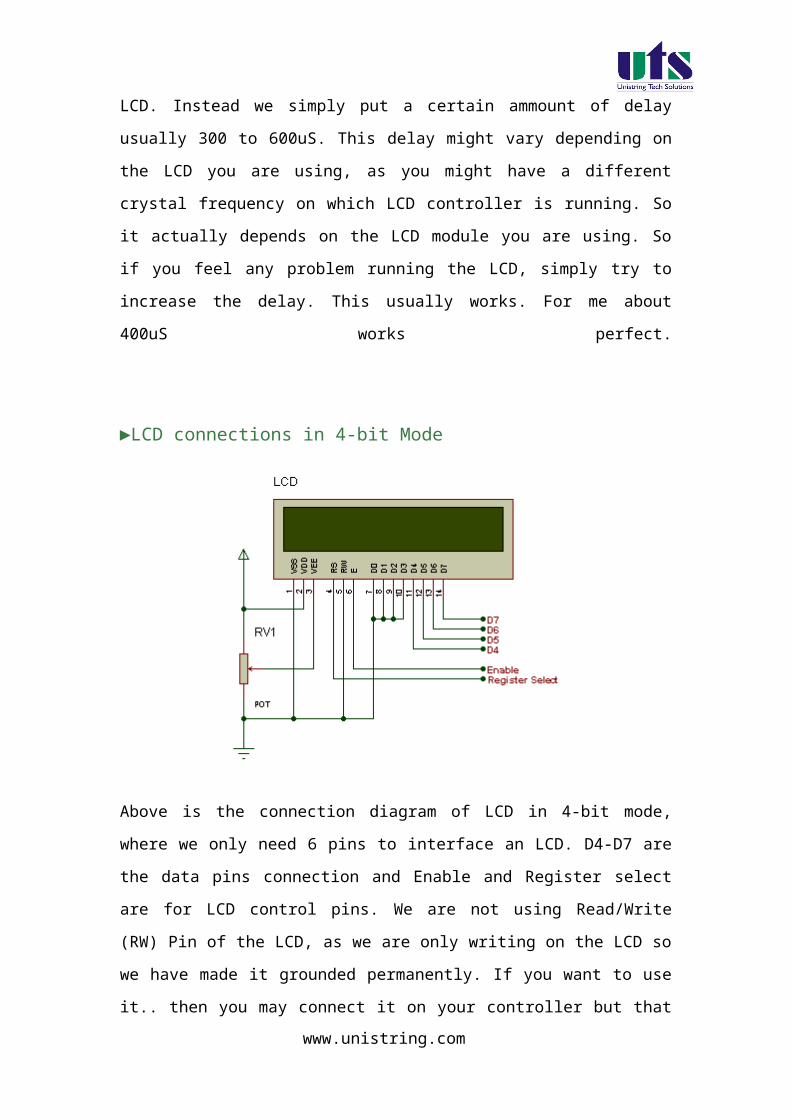
►LCD connections in 4-bit Mode
Above is the connection diagram of LCD in 4-bit mode, where we only need 6 pins to
interface an LCD. D4-D7 are the data pins connection and Enable and Register select
are for LCD control pins. We are not using Read/Write (RW) Pin of the LCD, as we
are only writing on the LCD so we have made it grounded permanently. If you want
to use it.. then you may connect it on your controller but that will only increase
another pin and does not make any big difference. Potentiometer RV1 is used to
control the LCD contrast. The unwanted data pins of LCD i.e. D0-D3 are connected
to ground.
►Sending data/command in 4-bit Mode
We will now look into the common steps to send data/command to LCD when
working in 4-bit mode. As i already explained in 4-bit mode data is sent nibble by
nibble, first we send higher nibble and then lower nibble. This means in both
command and data sending function we need to saperate the higher 4-bits and lower
4-bits.
www.unistring.com

The common steps are:
Mask lower 4-bits
Send to the LCD port
Send enable signal
Mask higher 4-bits
Send to LCD port
Send enable signal
We are done with the theory part now, In the next section we will take a look at the
programming microcontroller to control LCD in 4-bit mode.
Analog To Digital Convertor (ADC)
The ADC0804 is CMOS 8-Bit, successive approximation A/D converters
which use a modified potentiometric ladder and are designed to operate with the
processors/microcontrollers control bus via three-state outputs. These converters
appear to the processor as memory locations or I/O ports, and hence no interfacing
logic is required. The differential analog voltage input has good common- mode-
rejection and permits offsetting the analog zero-input voltage value. In addition, the
voltage reference input can be adjusted to allow encoding any smaller analog voltage
span to the full 8 bits of resolution.
Features:
• Compatible with 8051 µc derivatives-no interfacing logic needed - access time - 135 ns
• Easy interface to all microprocessors, or operates "stand alone"
• Differential analog voltage inputs Conversion Time <100µs
• Logic inputs and outputs meet both MOS and TTL voltage level specifications
www.unistring.com

• Works with 2.5V (LM336) voltage reference
• On-chip clock generator
• 0V to 5V analog input voltage range with single 5V supply
• No zero adjust required
• 0.3[Prime] standard width 20-pin DIP package
• 20-pin molded chip carrier or small outline package
• Operates ratiometrically or with 5 VDC, 2.5 VDC, or analog span adjusted voltage reference
PIN DIAGRAM:
Pin Number Description
1 CS - Chip Select (Active Low)
2 RD - Read (Active Low)
3 WR - Write (Active Low)
4 CLK IN - Clock IN
5 INTR - Interrupt (Active Low)
6 Vin+ - Analog Voltage Input
7 Vin- - Analog Voltage Input
www.unistring.com

8 AGND - Analog Ground
9 Vref/2 - Voltage Reference / 2
10 DGND - Digital Ground
11 DB7 - Data Bit 7 (MSB)
12 DB6 - Data Bit 6
13 DB5 - Data Bit 5
14 DB4 - Data Bit 4
15 DB3 - Data Bit 3
16 DB2 - Data Bit 2
17 DB1 - Data Bit 1
18 DB0 - Data Bit 0 (LSB)
19 CLKR - Clock Reset
20 Vcc - Positive Supply or Vref
Temperature Sensor Interfacing to Microcontroller using ADC804:
The ADC804 has 8-bit resolution with a maximum of 256 steps and the LM35 temperature sensor provides 10mV for every degree of temperature change.
We shall do Calibration such that for temperature range of 0 to 100 C, Voltage in at input of ADC will be 0 to 2.56 v.
we need to set Vref/2 = 1.28V
so step size will be 2560mv/256 = 10mv also for every degree change in
temp. LM35 output changesby10mv ,so every degree change in temp. will produce 1
unit change in digital out of ADC
Thus resolution of our system will be 1deg C , which is Smallest temp. that we can measure with this system. If resolution to be with 0.5deg C the Vref value to be adjusted to 0.64V.
The Vref voltage can be adjusted varying the POT R10.
R10 POT
a. Location near to the ADC chip
www.unistring.com
b. Adjusts the reference voltage to Analog to Digital Convertor (ADC).
Adjust the POT R10 and observe the voltage at Pin 9 (i.e Vref Pin of
the ADC) of U9 IC, i.e ADC0804. The reference value can be varied
from 0 to 2.5Volts by varying the POT.
Sending parallel data as either four or eight bits are the two primary modes of
operation. While there are secondary considerations and modes, deciding how to send
the data to the LCD is most critical decision to be made for an LCD interface
application. Eight bit mode is best used when speed is required in an application and
at least ten I/O pins are available. Four bit mode requires a minimum of six bits. To
wire a microcontroller to an LCD in four bit mode, just the top four bits (DB4-7) are
written to.
The "R/S" bit is used to select whether data or an instruction is being
transferred between the microcontroller and the LCD. If the Bit is set, then the byte at
the current LCD "Cursor" Position can be read or written. When the Bit is reset, either
an instruction is being sent to the LCD or the execution status of the last instruction is
read back (whether or not it has completed).
The different instructions available for use LCD are shown in below:
1. Clear display
2. Return home
4. Decrement cursor
www.unistring.com

6. Increment cursor
5. Shift display right
6. Increment cursor.
7. Shift display left
8. Display off,Cursor off
A. Display off,Cursor on
C. Display on,Cursor off
E. Display on Cursor blinking on
F. Display on Cursor blinking off
10. Shift cursor position to left
14. Shift cursor position to right
18. Shift the entire display to the left
1C. Shift the entire display to the right
80. Force cursor to beginning of 1st line
C0. Force cursor to beginning of 2nd line
38. 2 lines and 5x7 matrix
For further in detail description of the registers can go through the Data
sheet of 16X2 character LCD display.
Before you can send commands or data to the LCD module, the Module must be
initialized
LEDS
There are eight LEDs on the board from L0 to L7 for displaying eight bit information.
L0 is LSB and L7 is MSB. These eight LEDs are connected to CN4. so by connecting
any of the PORT to this CN4 and can write on to LEDs. The LEDS are connected in
common cathode fashion. So the data written on Port will be displayed with LEDs
indication directly.
PUSH Buttons
www.unistring.com

There are Four pushbuttons are available in the Kit named as SW1 to PSB4. These
push buttons are connected to CN9 on the Board.
www.unistring.com

Experimental Procedure For LAB
www.unistring.com
1. Serial Data Transmission using 8051 microcontroller in different modes.
Aim: Write a program for serial communication using RS232 interface and communicate with PC using polling mode.
Introduction:
In this experiment a program is written in C language to read data from PC
and the same data is echoed back to the computer through RS232 interface
available on the board.
The program flow chart Write a program for serial communication using polling method. Compile the program and generate Hex file. The generated hex file will be downloaded in to the MC and
verify the result.
KIEL software is used for compilation of C files and the hex file can be generated. Experimental procedure:
Step1:
Open the Kiel ide and you can see a menu as shown in the figure.
www.unistring.com
Step 2:
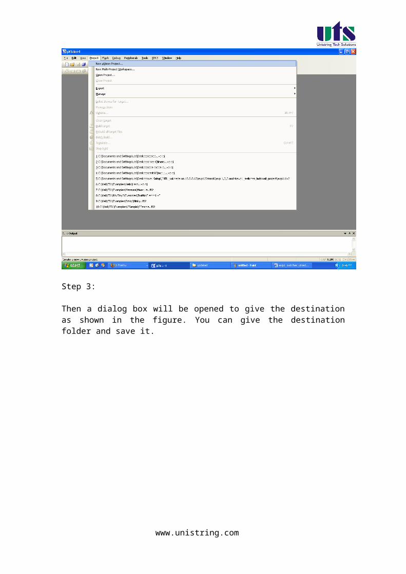
To create a new project just click the project menu and click new micro vision project , as shown in below figure.
www.unistring.com

Step 3:
Then a dialog box will be opened to give the destination as shown in the figure. You can give the destination folder and save it.
www.unistring.com

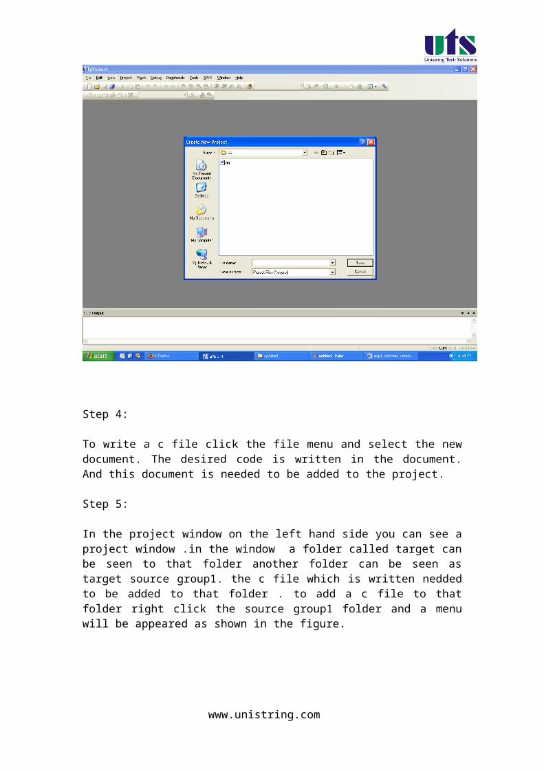
Step 4:
To write a c file click the file menu and select the new document. The desired code is written in the document. And this document is needed to be added to the project.
Step 5:
In the project window on the left hand side you can see a project window .in the window a folder called target can be seen to that folder another folder can be seen as target source group1. the c file which is written needed to be added to that folder . to add a c file to that folder right click the source group1 folder and a menu will be appeared as shown in the figure.
www.unistring.com

From that menu you can see add files to source group option. If you click that option the c file will be added to the project.
Step 6:
Before building the project some settings are to made, from the main menu click the flash, you can see the option as configure flash tools . You click that option you can find a menu as shown in the figure.
www.unistring.com

From that menu click output and select an option called create hex file. And in the target menu give the oscillator frequency as 11.0592.
Step 7:
Now all the hard work we have done to build the project and to create the hex file From the main menu select the project and in that an option called build target can be seen , just click that . if all the coding is correct and the syntaxes are correct an hex file will be generated.
Down loading the hex file to the target:
Open the Flash Magic tool for downloading into the Microcontroller Board. Click on Device menu select option you will be popped up with a window named choose device. Under choose device options select 8051 and click on Ok button to open flash magic tool to download the hex file in to the MC and is as shown below.
www.unistring.com

(1) Flash Magic Opens as shown in the figure
Change setting for Flash Magic as shown in the above figureCOM Port Choose the Appropriate COM Port of the computer. Generally it is COM1Baud Rate 9600Device 89V51RD2Interface None(ISP)Oscillator Freq (MHZ) 11.0592Tick Erase All Flash+Security+ClksTick Verify after Programming
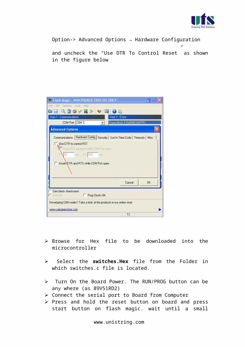
Now Goto
Option-> Advanced Options → Hardware Configuration and uncheck the “Use DTR To Control Reset” as shown in the figure below
www.unistring.com

Browse for Hex file to be downloaded into the microcontroller
Select the SERIAL. Hex file from the Folder in which SERIAL.c file is located.
Turn On the Board Power. The RUN/PROG button can be any where (as 89V51RD2)
Connect the serial port to Board from Computer Press and hold the reset button on board and press start
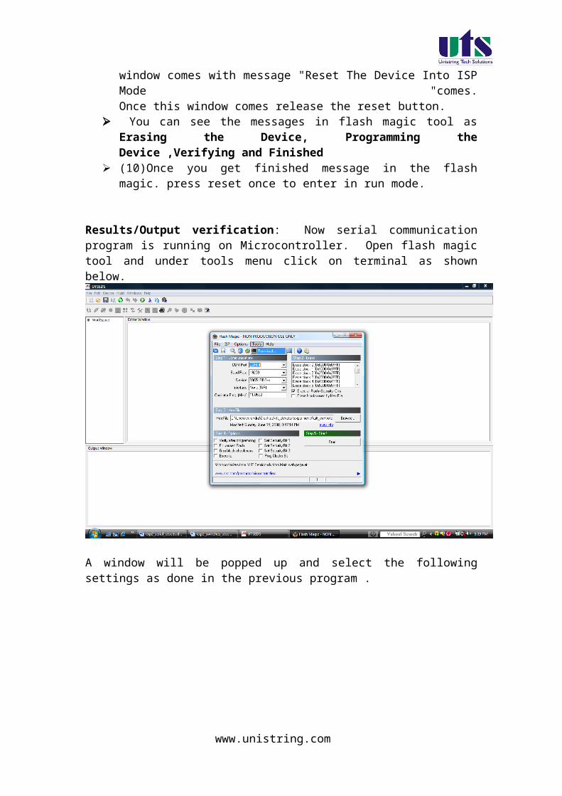
button on flash magic. wait until a small window comes with message "Reset The Device Into ISP Mode "comes.Once this window comes release the reset button.
You can see the messages in flash magic tool as Erasing the Device, Programming the Device ,Verifying and Finished
(10)Once you get finished message in the flash magic. press reset once to enter in run mode.
www.unistring.com

Results/Output verification: Now serial communication program is running on Microcontroller. Open flash magic tool and under tools menu click on terminal as shown below.
A window will be popped up and select the following settings as done in the previous program .
You can observe a black window appearing having two parts. One is output and another one is input to communicate to the serial port. Press reset button and you can see a message saying “press any
www.unistring.com

key” under output pane. Now what ever the message you type at input pane, the same message will be displayed on the output pane.
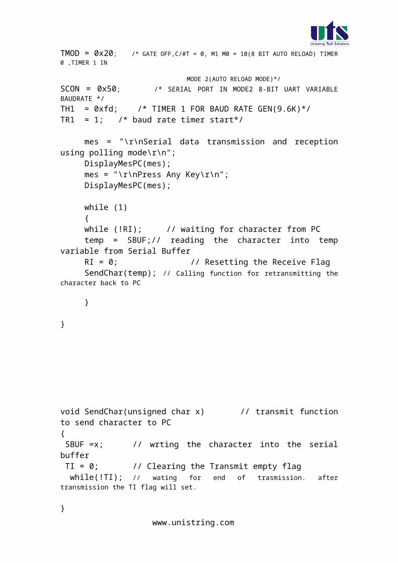
C SOURCE CODE
www.unistring.com

// This program reads the character from serial port and retransmits the same back to PC
#include <reg51.h> /* define 8051 registers */void SendChar(unsigned char x);void DisplayMesPC(unsigned char *);
unsigned char *mes;
void main (void) { /* main program */ unsigned char temp;
TMOD = 0x20; /* GATE OFF,C/#T = 0, M1 M0 = 10(8 BIT AUTO RELOAD) TIMER 0 ,TIMER 1 IN
MODE 2(AUTO RELOAD MODE)*/
SCON = 0x50; /* SERIAL PORT IN MODE2 8-BIT UART VARIABLE BAUDRATE */TH1 = 0xfd; /* TIMER 1 FOR BAUD RATE GEN(9.6K)*/TR1 = 1; /* baud rate timer start*/
mes = "\r\nSerial data transmission and reception using polling mode\r\n";
DisplayMesPC(mes);mes = "\r\nPress Any Key\r\n";DisplayMesPC(mes);
while (1) { while (!RI); // waiting for character from PC temp = SBUF;// reading the character into temp variable from
Serial BufferRI = 0; // Resetting the Receive FlagSendChar(temp); // Calling function for retransmitting the character
back to PC
}
}
void SendChar(unsigned char x) // transmit function to send character to PC{
www.unistring.com

SBUF =x; // wrting the character into the serial buffer TI = 0; // Clearing the Transmit empty flag while(!TI); // wating for end of trasmission. after transmission the TI flag will set. }
void DisplayMesPC(unsigned char *mes){int counter;for (counter=0;mes[counter]!='\0';counter++) { SendChar(mes[counter]); }}
HARWARE CONFIGURATION
To test the board
Power supply cable should be connected to the M7 Board and serial cable must be connected to the computer. Now go to the start menu and in that go to the all programs menu . in that go to the accessories , there in the sub menu you will find a menu called communications. In the communications menu select the hyper terminal.
After doing so the following window will be appeared. Enter any connection name in block.
www.unistring.com

Select COM1 and then click ok
www.unistring.com

In that select the new connection and set the options as
Restore Defaults.
This will keep the default baud rate as 9600,1 start bit,1 stop bit and hardware as none.
www.unistring.com

To check the output now, if any key is pressed from the keyboard that will be displayed on the hyper terminal.
Basic Theory of 8051 Serial commutations
UART (Universal Asynchronous Receiver and Transmitter)
One of the microcontroller features making it so powerful is an integrated
UART, better known as a serial port. It is a full-duplex port, thus being able to
transmit and receive data simultaneously and at different baud rates. Without
it, serial data send and receive would be an enormously complicated part of
the program in which the pin state is constantly changed and checked at
regular intervals. When using UART, all the programmer has to do is to simply
select serial port mode and baud rate. When it's done, serial data transmit is
nothing but writing to the SBUF register, while data receive represents
reading the same register. The microcontroller takes care of not making any
error during data transmission.
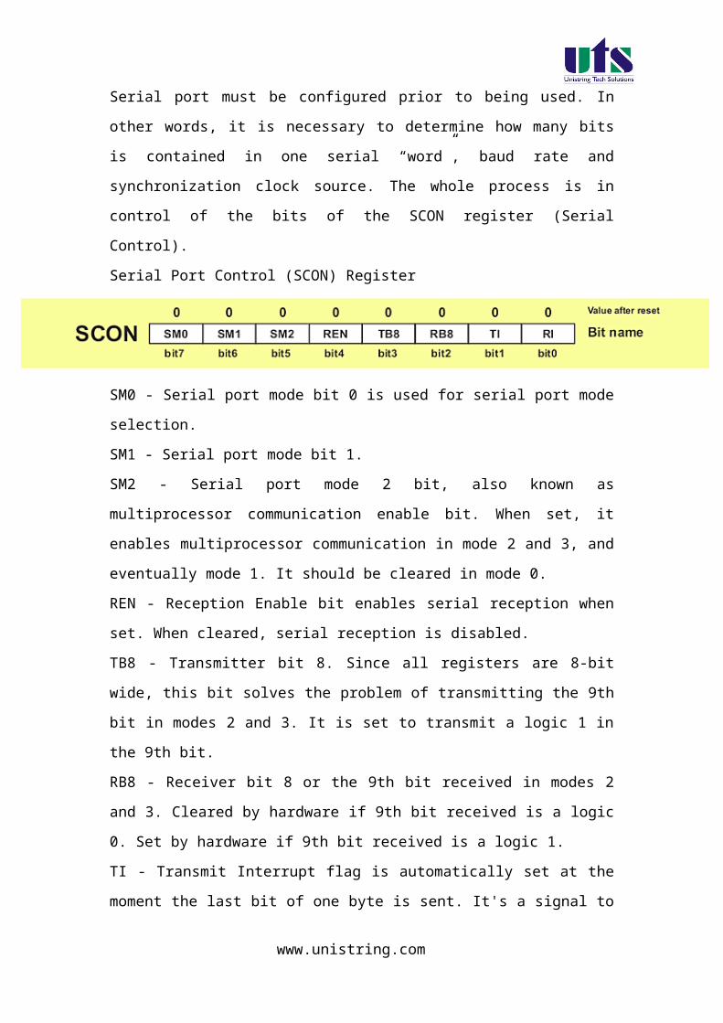
Serial port must be configured prior to being used. In other words, it is
necessary to determine how many bits is contained in one serial “word”, baud
rate and synchronization clock source. The whole process is in control of the
bits of the SCON register (Serial Control).
Serial Port Control (SCON) Register
SM0 - Serial port mode bit 0 is used for serial port mode selection.
www.unistring.com

SM1 - Serial port mode bit 1.
SM2 - Serial port mode 2 bit, also known as multiprocessor communication
enable bit. When set, it enables multiprocessor communication in mode 2 and
3, and eventually mode 1. It should be cleared in mode 0.
REN - Reception Enable bit enables serial reception when set. When cleared,
serial reception is disabled.
TB8 - Transmitter bit 8. Since all registers are 8-bit wide, this bit solves the
problem of transmitting the 9th bit in modes 2 and 3. It is set to transmit a
logic 1 in the 9th bit.
RB8 - Receiver bit 8 or the 9th bit received in modes 2 and 3. Cleared by
hardware if 9th bit received is a logic 0. Set by hardware if 9th bit received is a
logic 1.
TI - Transmit Interrupt flag is automatically set at the moment the last bit of
one byte is sent. It's a signal to the processor that the line is available for a
new byte transmit. It must be cleared from within the software.
RI - Receive Interrupt flag is automatically set upon one byte receive. It
signals that byte is received and should be read quickly prior to being
replaced by a new data. This bit is also cleared from within the software.
As seen, serial port mode is selected by combining the SM0 and SM2 bits:
SM0 SM1 Mode Description Baud Rate
0 0 08-bit Shift
Register1/12 the quartz frequency
0 1 1 8-bit UART Determined by the timer 1
1 0 2 9-bit UART1/32 the quartz frequency (1/64 the quartz
frequency)
1 1 3 9-bit UART Determined by the timer 1
www.unistring.com
In mode 0, serial data are transmitted and received through the RXD pin,
while the TXD pin output clocks. The bout rate is fixed at 1/12 the oscillator
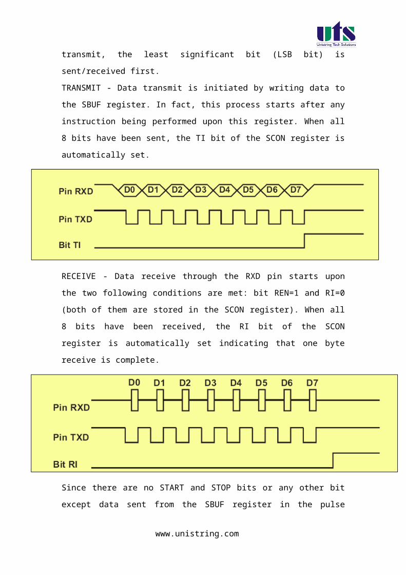
frequency. On transmit, the least significant bit (LSB bit) is sent/received first.
TRANSMIT - Data transmit is initiated by writing data to the SBUF register. In
fact, this process starts after any instruction being performed upon this
register. When all 8 bits have been sent, the TI bit of the SCON register is
automatically set.
RECEIVE - Data receive through the RXD pin starts upon the two following
conditions are met: bit REN=1 and RI=0 (both of them are stored in the SCON
register). When all 8 bits have been received, the RI bit of the SCON register
is automatically set indicating that one byte receive is complete.
www.unistring.com
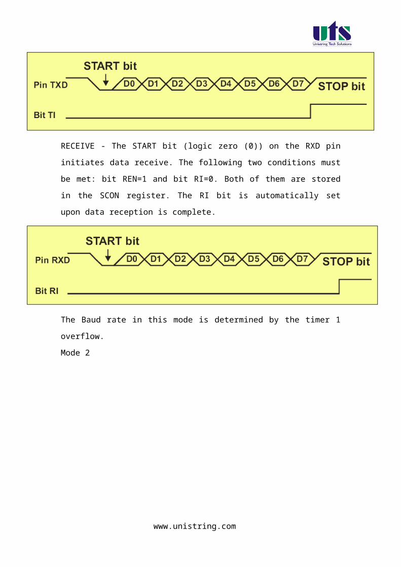
Since there are no START and STOP bits or any other bit except data sent
from the SBUF register in the pulse sequence, this mode is mainly used when
the distance between devices is short, noise is minimized and operating
speed is of importance. A typical example is I/O port expansion by adding a
cheap IC (shift registers 74HC595, 74HC597 and similar).
Mode 1
In mode 1, 10 bits are transmitted through the TXD pin or received through
the RXD pin in the following manner: a START bit (always 0), 8 data bits (LSB
first) and a STOP bit (always 1). The START bit is only used to initiate data
receive, while the STOP bit is automatically written to the RB8 bit of the
SCON register.
www.unistring.com

TRANSMIT - Data transmit is initiated by writing data to the SBUF register.
End of data transmission is indicated by setting the TI bit of the SCON
register.
RECEIVE - The START bit (logic zero (0)) on the RXD pin initiates data
receive. The following two conditions must be met: bit REN=1 and bit RI=0.
Both of them are stored in the SCON register. The RI bit is automatically set
upon data reception is complete.
The Baud rate in this mode is determined by the timer 1 overflow.
Mode 2
www.unistring.com

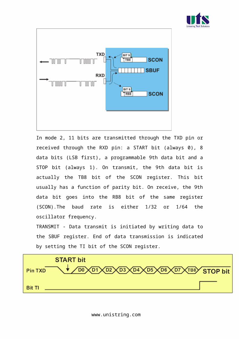
In mode 2, 11 bits are transmitted through the TXD pin or received through
the RXD pin: a START bit (always 0), 8 data bits (LSB first), a programmable
9th data bit and a STOP bit (always 1). On transmit, the 9th data bit is actually
the TB8 bit of the SCON register. This bit usually has a function of parity bit.
On receive, the 9th data bit goes into the RB8 bit of the same register
(SCON).The baud rate is either 1/32 or 1/64 the oscillator frequency.
TRANSMIT - Data transmit is initiated by writing data to the SBUF register.
End of data transmission is indicated by setting the TI bit of the SCON
register.
RECEIVE - The START bit (logic zero (0)) on the RXD pin initiates data
receive. The following two conditions must be met: bit REN=1 and bit RI=0.
Both of them are stored in the SCON register. The RI bit is automatically set
upon data reception is complete.
www.unistring.com

Mode 3
Mode 3 is the same as Mode 2 in all respects except the baud rate. The baud
rate in Mode 3 is variable.
The parity bit is the P bit of the PSW register. The simplest way to check
correctness of the received byte is to add a parity bit to it. Simply, before
initiating data transmit, the byte to transmit is stored in the accumulator and
the P bit goes into the TB8 bit in order to be “a part of the message”. The
procedure is opposite on receive, received byte is stored in the accumulator
and the P bit is compared with the RB8 bit. If they are the same- everything is
OK!
www.unistring.com

Baud Rate
Baud Rate is a number of sent/received bits per second. In case the UART is
used, baud rate depends on: selected mode, oscillator frequency and in some
cases on the state of the SMOD bit of the SCON register. All the necessary
formulas are specified in the table:
Baud Rate BitSMOD
Mode 0 Fosc. / 12
Mode 11 Fosc.
16 12 (256-TH1)BitSMOD
Mode 2Fosc. / 32
Fosc. / 64
1
0
Mode 31 Fosc.
16 12 (256-TH1)
www.unistring.com
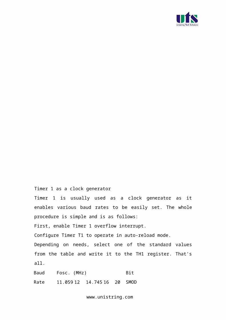
Timer 1 as a clock generator
Timer 1 is usually used as a clock generator as it enables various baud rates
to be easily set. The whole procedure is simple and is as follows:
First, enable Timer 1 overflow interrupt.
Configure Timer T1 to operate in auto-reload mode.
Depending on needs, select one of the standard values from the table and
write it to the TH1 register. That's all.
Baud RateFosc. (MHz)
Bit SMOD11.0592 12 14.7456 16 20
150 40 h 30 h 00 h 0
300 A0 h 98 h 80 h 75 h 52 h 0
600 D0 h CC h C0 h BB h A9 h 0
1200 E8 h E6 h E0 h DE h D5 h 0
2400 F4 h F3 h F0 h EF h EA h 0
4800 F3 h EF h EF h 1
4800 FA h F8 h F5 h 0
9600 FD h FC h 0
9600 F5 h 1
19200 FD h FC h 1
38400 FE h 1
76800 FF h 1
Multiprocessor Communication
www.unistring.com

As you may know, additional 9th data bit is a part of message in mode 2 and
3. It can be used for checking data via parity bit. Another useful application of
this bit is in communication between two or more microcontrollers, i.e.
multiprocessor communication. This feature is enabled by setting the SM2 bit
of the SCON register. As a result, after receiving the STOP bit, indicating end
of the message, the serial port interrupt will be generated only if the bit RB8 =
1 (the 9th bit).
This is how it looks like in practice:
Suppose there are several microcontrollers sharing the same interface. Each
of them has its own address. An address byte differs from a data byte
because it has the 9th bit set (1), while this bit is cleared (0) in a data byte.
When the microcontroller A (master) wants to transmit a block of data to one
of several slaves, it first sends out an address byte which identifies the target
slave. An address byte will generate an interrupt in all slaves so that they can
examine the received byte and check whether it matches their address.
Of course, only one of them will match the address and immediately clear the
SM2 bit of the SCON register and prepare to receive the data byte to come.
Other slaves not being addressed leave their SM2 bit set ignoring the coming
data bytes.
www.unistring.com
www.unistring.com

Experiment – 1b
Write a program for serial communication using Interrupt
Aim: Write a program for serial communication using RS232 interface and communicate with PC using interrupt mode.
Introduction:
In this experiment a program is written in C language to read data
from PC and the same data is echoed back to the computer through
RS232 interface available on the board.
The program flow chart Write a program for serial communication using
interrupt method. Compile the program and generate Hex file. The generated hex file will be downloaded in to the MC
and verify the result.
KIEL software is used for compilation of C files and the hex file can be generated. Experimental procedure:
Step1:
Open the kiel ide and you can see a menu as shoen in the figure.
www.unistring.com
Step 2:
To create a new project just click the project menu and click new microvision project , as shown in below figure.
www.unistring.com
Step 3:
Then a dialog box will be opened to give the destination as shown in the figure. You can give the destination folder and save it.
www.unistring.com

Step 4:
To write a c file click the file menu and select the new document. The desired code is written in the document. And this document is needed to be added to the project.
Step 5:
In the project window on the left hand side you can see a project window .in the window a folder called target can be seen to that folder another folder can be seen as target source group1. the c file which is written nedded to be added to that folder . to add a c file to that folder right click the source group1 folder and a menu will be appeared as shown in the figure.
www.unistring.com

From that menu you can see add files to source group option. If you click that option the c file will be added to the project.
Step 6:
Before bulding the project some settings are to made, from the main menu click the flash, you can see the option as configure flash tools . you click that option you can find a menu as shown in the figure.
www.unistring.com
From that menu click output and select an option called create hex file. And in the target menu give the oscillator frequency as 11.0592.
Step 7:
Now all the hard work we have done to build the project and to create the hex file From the main menu select the project and in that an option called build target can be seen , just click that . if all the coding is correct and the syntaxes are correct an hex file will be generated.
Down loading the hex file to the target:
Open the Flash Magic tool for downloading into the Microcontroller Board. Click on Device menu select option you will be popped up with a window named choose device. Under choose device options select 8051 and click on Ok button to open flash magic tool to download the hex file in to the MC and is as shown below.
www.unistring.com
(2) Flash Magic Opens as shown in the figure
Change setting for Flash Magic as shown in the above figureCOM Port Choose the Appropriate COM Port of the computer. Generally it is COM1Baud Rate 9600Device 89V51RD2Interface None(ISP)Oscillator Freq (MHZ) 11.0592Tick Erase All Flash+Security+ClksTick Verify after Programming
Now Goto
Option-> Advanced Options → Hardware Configuration and uncheck the “Use DTR To Control Reset” as shown in the figure below
www.unistring.com

Browse for Hex file to be downloaded into the microcontroller
Select the switches.Hex file from the Folder in which switches.c file is located.
Turn On the Board Power. The RUN/PROG button can be any where (as 89V51RD2)
Connect the serial port to Board from Computer Press and hold the reset button on board and press start
button on flash magic. wait until a small window comes with message "Reset The Device Into ISP Mode "comes.Once this window comes release the reset button.
You can see the messages in flash magic tool as Erasing the Device, Programming the Device ,Verifying and Finished
(10)Once you get finished message in the flash magic. press reset once to enter in run mode.
Results/Output verification: Now serial communication program is running on Microcontroller. Open flash magic tool and under tools menu click on terminal as shown below.
www.unistring.com

A window will be popped up and select the following settings as done in the previous program .
You can observe a black window appearing having two parts. One is output and another one is input to communicate to the serial port. Press reset button and you can see a message saying “press any key” under output pane. Now what ever the message you type at input pane, the same message will be displayed on the output pane.
www.unistring.com

C SOURCE CODE // This program reads the character from serial port and retransmits the same back to PC
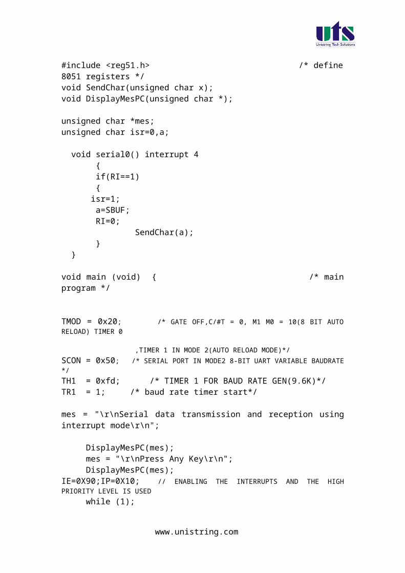
#include <reg51.h> /* define 8051 registers */void SendChar(unsigned char x);void DisplayMesPC(unsigned char *);
unsigned char *mes;unsigned char isr=0,a;
void serial0() interrupt 4 { if(RI==1) { isr=1; a=SBUF; RI=0; SendChar(a); }
}
void main (void) { /* main program */
TMOD = 0x20; /* GATE OFF,C/#T = 0, M1 M0 = 10(8 BIT AUTO RELOAD) TIMER 0
,TIMER 1 IN MODE 2(AUTO RELOAD MODE)*/SCON = 0x50; /* SERIAL PORT IN MODE2 8-BIT UART VARIABLE BAUDRATE */TH1 = 0xfd; /* TIMER 1 FOR BAUD RATE GEN(9.6K)*/TR1 = 1; /* baud rate timer start*/
mes = "\r\nSerial data transmission and reception using interrupt mode\r\n";
www.unistring.com

DisplayMesPC(mes);mes = "\r\nPress Any Key\r\n";DisplayMesPC(mes);
IE=0X90;IP=0X10; // ENABLING THE INTERRUPTS AND THE HIGH PRIORITY LEVEL IS USED
while (1);
}
void SendChar(unsigned char x) // transmit function to send character to PC{ SBUF =x; // wrting the character into the serial buffer TI = 0; // Clearing the Transmit empty flag while(!TI); // wating for end of trasmission. after transmission the TI flag will set. }
void DisplayMesPC(unsigned char *mes){int counter;for (counter=0;mes[counter]!='\0';counter++) { SendChar(mes[counter]); }}
HARWARE CONFIGURATION
To test the board
Power supply cable should be connected to the M7 Board and serial cable must be connected to the computer. Now go to the start menu and in that go to the all programs menu . in that go to the accessories , there in the sub menu you will find a menu called communications. In the communications menu select the hyper terminal.
After doing so the following window will be appeared. Enter any connection name in block.
www.unistring.com

Select COM1 and then click ok
www.unistring.com

In that select the new connection and set the options as restore to defaults.This will keep the default baud rate as 9600,1 start bit,1 stop bit and hardware as none.
www.unistring.com

To check the output now, if any key is pressed from the keyboard that will be displayed on the hyper terminal.
Exercise: 1. Write a program for serial communication to PC and when a character is sent to Microcontroller, it has to send the same character two times. 2. Write a program for serial communication to PC and when a character is sent to Microcontroller, the same character must be sent back to PC but with case change (i.e. if a lower case character is sent to microcontroller, upper case character must be sent to PC and vice versa).
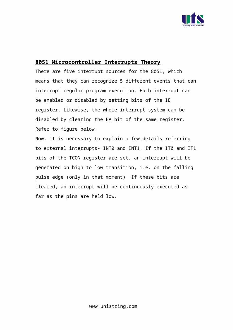
8051 Microcontroller Interrupts Theory
There are five interrupt sources for the 8051, which means that they can
recognize 5 different events that can interrupt regular program execution.
Each interrupt can be enabled or disabled by setting bits of the IE register.
www.unistring.com

Likewise, the whole interrupt system can be disabled by clearing the EA bit of
the same register. Refer to figure below.
Now, it is necessary to explain a few details referring to external interrupts-
INT0 and INT1. If the IT0 and IT1 bits of the TCON register are set, an
interrupt will be generated on high to low transition, i.e. on the falling pulse
edge (only in that moment). If these bits are cleared, an interrupt will be
continuously executed as far as the pins are held low.
IE Register (Interrupt Enable)
EA - global interrupt enable/disable:
0 - disables all interrupt requests.
1 - enables all individual interrupt requests.
www.unistring.com

ES - enables or disables serial interrupt:
0 - UART system cannot generate an interrupt.
1 - UART system enables an interrupt.
ET1 - bit enables or disables Timer 1 interrupt:
0 - Timer 1 cannot generate an interrupt.
1 - Timer 1 enables an interrupt.
EX1 - bit enables or disables external 1 interrupt:
0 - change of the pin INT0 logic state cannot generate an interrupt.
1 - enables an external interrupt on the pin INT0 state change.
ET0 - bit enables or disables timer 0 interrupt:
0 - Timer 0 cannot generate an interrupt.
1 - enables timer 0 interrupt.
EX0 - bit enables or disables external 0 interrupt:
0 - change of the INT1 pin logic state cannot generate an interrupt.
1 - enables an external interrupt on the pin INT1 state change.
Interrupt Priorities
It is not possible to foreseen when an interrupt request will arrive. If several
interrupts are enabled, it may happen that while one of them is in progress,
another one is requested. In order that the microcontroller knows whether to
continue operation or meet a new interrupt request, there is a priority list
instructing it what to do.
The priority list offers 3 levels of interrupt priority:
Reset! The apsolute master. When a reset request arrives, everything is
stopped and the microcontroller restarts.
Interrupt priority 1 can be disabled by Reset only.
Interrupt priority 0 can be disabled by both Reset and interrupt priority 1.
The IP Register (Interrupt Priority Register) specifies which one of existing
interrupt sources have higher and which one has lower priority. Interrupt
priority is usually specified at the beginning of the program. According to that,
there are several possibilities:
If an interrupt of higher priority arrives while an interrupt is in progress, it will
be immediately stopped and the higher priority interrupt will be executed first.
www.unistring.com
If two interrupt requests, at different priority levels, arrive at the same time
then the higher priority interrupt is serviced first.
If the both interrupt requests, at the same priority level, occur one after
another, the one which came later has to wait until routine being in progress
ends.
If two interrupt requests of equal priority arrive at the same time then the
interrupt to be serviced is selected according to the following priority list:
External interrupt INT0
Timer 0 interrupt
External Interrupt INT1
Timer 1 interrupt
Serial Communication Interrupt
IP Register (Interrupt Priority)
The IP register bits specify the priority level of each interrupt (high or low
priority).
www.unistring.com

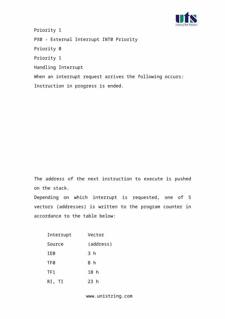
PS - Serial Port Interrupt priority bit
Priority 0
Priority 1
PT1 - Timer 1 interrupt priority
Priority 0
Priority 1
PX1 - External Interrupt INT1 priority
Priority 0
Priority 1
PT0 - Timer 0 Interrupt Priority
Priority 0
Priority 1
PX0 - External Interrupt INT0 Priority
Priority 0
Priority 1
Handling Interrupt
When an interrupt request arrives the following occurs:
Instruction in progress is ended.
The address of the next instruction to execute is pushed on the stack.
Depending on which interrupt is requested, one of 5 vectors (addresses) is
written to the program counter in accordance to the table below:
Interrupt Source Vector (address)
IE0 3 h
www.unistring.com

TF0 B h
TF1 1B h
RI, TI 23 h
All addresses are in hexadecimal format
These addresses store appropriate subroutines processing interrupts. Instead
of them, there are usually jump instructions specifying locations on which
these subroutines reside.
When an interrupt routine is executed, the address of the next instruction to
execute is popped from the stack to the program counter and interrupted
program resumes operation from where it left off.
From the moment an interrupt is enabled, the microcontroller is on alert all the
time. When an interrupt request arrives, the program execution is stopped,
electronics recognizes the source and the program “jumps” to the appropriate
address (see the table above). This address usually stores a jump instruction
specifying the start of appropriate subroutine. Upon its execution, the program
resumes operation from where it left off.
Experiment – 1c
Serial communication with different Baud rates
Aim: Write a program for serial communication using RS232 interface and communicate with PC using different baud rates.
www.unistring.com
Introduction:
In this experiment a program is written in C language to read data
from PC and the same data is echoed back to the computer through
RS232 interface available on the board.
The program flow chart Write a program for serial communication with different
baud rates. Compile the program and generate Hex file. The generated hex file will be downloaded in to the MC
and verify the result.
KIEL software is used for compilation of C files and the hex file can be generated. Experimental procedure:
Step1:
Open the kiel ide and you can see a menu as shoen in the figure.
www.unistring.com

Step 2:
To create a new project just click the project menu and click new microvision project , as shown in below figure.
Step 3:
Then a dialog box will be opened to give the destination as shown in the figure. You can give the destination folder and save it.
www.unistring.com

Step 4:
To write a c file click the file menu and select the new document. The desired code is written in the document. And this document is needed to be added to the project.
Step 5:
In the project window on the left hand side you can see a project window .in the window a folder called target can be seen to that folder another folder can be seen as target source group1. the c file which is written nedded to be added to that folder . to add a c file to that folder right click the source group1 folder and a menu will be appeared as shown in the figure.
www.unistring.com

From that menu you can see add files to source group option. If you click that option the c file will be added to the project.
Step 6:
Before bulding the project some settings are to made, from the main menu click the flash, you can see the option as configure flash tools . you click that option you can find a menu as shown in the figure.
www.unistring.com

From that menu click output and select an option called create hex file. And in the target menu give the oscillator frequency as 11.0592.
Step 7:
Now all the hard work we have done to build the project and to create the hex file From the main menu select the project and in that an option called build target can be seen , just click that . if all the coding is correct and the syntaxes are correct an hex file will be generated.
Down loading the hex file to the target:
Open the Flash Magic tool for downloading into the Microcontroller Board. Click on Device menu select option you will be popped up with a window named choose device. Under choose device options select 8051 and click on Ok button to open flash magic tool to download the hex file in to the MC and is as shown below.
www.unistring.com
(3) Flash Magic Opens as shown in the figure
Change setting for Flash Magic as shown in the above figureCOM Port Choose the Appropriate COM Port of the computer. Generally it is COM1Baud Rate 9600Device 89V51RD2Interface None(ISP)Oscillator Freq (MHZ) 11.0592Tick Erase All Flash+Security+ClksTick Verify after Programming
Now Goto
Option-> Advanced Options → Hardware Configuration and uncheck the “Use DTR To Control Reset” as shown in the figure below
www.unistring.com

Browse for Hex file to be downloaded into the microcontroller
Select the switches.Hex file from the Folder in which switches.c file is located.
Turn On the Board Power. The RUN/PROG button can be any where (as 89V51RD2)
Connect the serial port to Board from Computer Press and hold the reset button on board and press start
button on flash magic. wait until a small window comes with message "Reset The Device Into ISP Mode "comes.Once this window comes release the reset button.
You can see the messages in flash magic tool as Erasing the Device, Programming the Device ,Verifying and Finished
(10)Once you get finished message in the flash magic. press reset once to enter in run mode.
Results/Output verification: Now serial communication program is running on Microcontroller. Open flash magic tool and under tools menu click on terminal as shown below.
www.unistring.com

A window will be popped up and select the following settings as done in the previous program .
You can observe a black window appearing having two parts. One is output and another one is input to communicate to the serial port. Press reset button and you can see a message saying “press any key” under output pane. Now what ever the message you type at input pane, the same message will be displayed on the output pane.
www.unistring.com

C SOURCE CODE
// This program reads the character from serial port and retransmits the same back to PC
#include <reg51.h> /* define 8051 registers */
FUNCTION PROTOTYPE DECLARATION
www.unistring.com

void SendChar(unsigned char x);void DisplayMesPC(unsigned char *);void baudrate(unsigned int a,unsigned char mode);
VARIABLE DECLARATION
unsigned char *mes;unsigned char isr=0,a;
INTERRUPT SERVICE ROUTINE
void serial0() interrupt 4 { if(RI==1) { isr=1; a=SBUF; RI=0; } }
MAIN CODE STARTS HERE
void main (void) { /* main program */ baudrate(9600,1); // function for different baud rates
mes = "\r\nPress Any Key\r\n";DisplayMesPC(mes);
while (1) { if(isr==1) {
SendChar(a); // Calling function for retransmitting the character back to PC
isr=0;}//-----------------------------------------SendChar(temp); //
Calling function for retransmitting the character back to PC}
}
FUNCTION FOR SENDING A CHARACTER TO TX REGISTER
www.unistring.com
void SendChar(unsigned char x) // transmit function to send character to PC{ SBUF =x; // wrting the character into the serial buffer TI = 0; // Clearing the Transmit empty flag while(!TI); // wating for end of trasmission. after transmission the TI flag will set. }
FUNCTION FOR SENDING A STRING TO TX REGISTER
void DisplayMesPC(unsigned char *mes){int counter;for (counter=0;mes[counter]!='\0';counter++) { SendChar(mes[counter]); }}
// VALUE FOR THE 1200 BAUD RATE IS 0XE8// VALUE FOR THE 2400 BAUD RATE IS 0XF4// VALUE FOR THE 4800 BAUD RATE IS 0XFA// VALUE FOR THE 9600 BAUD RATE IS 0XFD
void baudrate(unsigned int a,unsigned char mode){ TMOD = 0x20; /* GATE OFF,C/#T = 0, M1 M0 = 10(8
BIT AUTO RELOAD) TIMER 0 ,TIMER 1 IN MODE 2(AUTO RELOAD MODE)*/
SCON = 0x50; /* SERIAL PORT IN MODE2 8-BIT UART VARIABLE BAUDRATE */// TH1 = a; /* TIMER 1 FOR BAUD RATE GEN(9.6K)*/ if(mode==0)
{ PCON=0x00;if(a==1200) { TH1=0xfd; }if(a==2400) { TH1=0xf4; }
www.unistring.com

if(a==4800) { TH1=0xfa; } if(a==9600) { TH1=0xfd; }}else if(mode==1){ PCON=0x80; if(a==19200) { TH1=0xfd; } if(a==9600) { TH1=0xfa; } if(a==4800) { TH1=0xf4; } if(a==2400) { TH1=0xe8; }} TR1 = 1; /* baud rate timer start*/ IE=0X90;IP=0X10; // ENABLING THE
INTERRUPTS AND THE HIGH PRIORITY LEVEL IS USED}
HARWARE CONFIGURATION
To test the board
Power supply cable should be connected to the M7 Board and serial cable must be connected to the computer. Now go to the start menu and in that go to the all programs menu . in that go to the accessories , there in the sub menu you will find a menu called communications. In the communications menu select the hyper terminal.
After doing so the following window will be appeared. Enter any connection name in block.
www.unistring.com

Select COM1 and then click ok
www.unistring.com
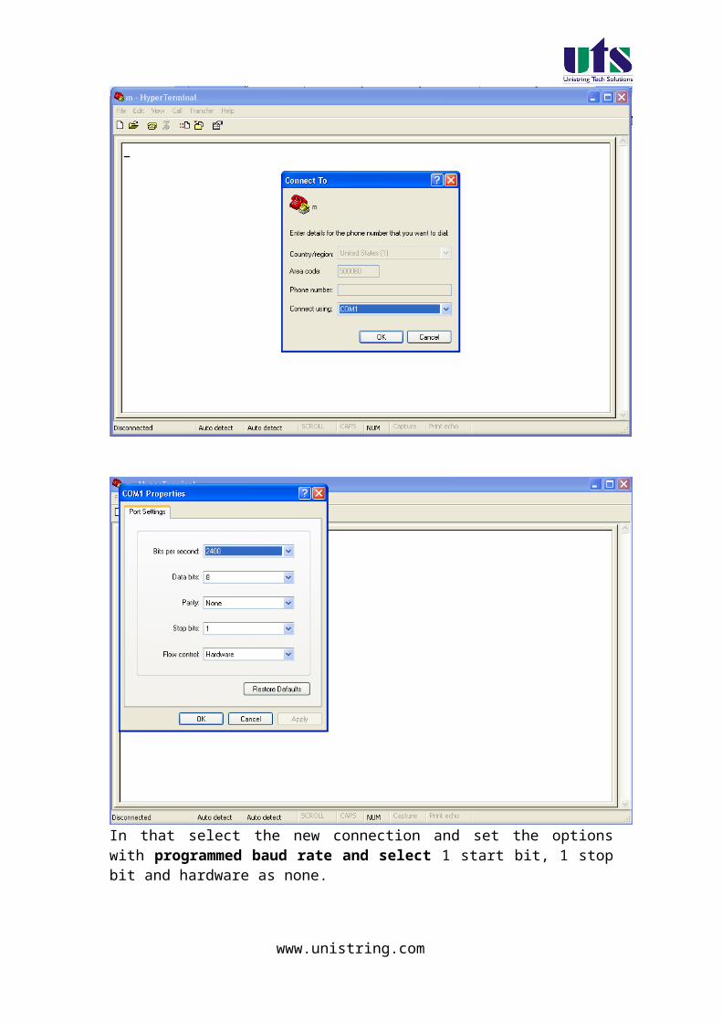
In that select the new connection and set the options with programmed baud rate and select 1 start bit, 1 stop bit and hardware as none.
www.unistring.com

To check the output now, if any key is pressed from the keyboard that will be displayed on the hyper terminal.
2. Look up tables for 8051.
www.unistring.com
Experiment – 2a
Write a program for implementing a sin lookup table on 8051
Aim:
a. Write a program for Implementing the SIN look up table for 8051
Introduction:
In this experiment a program is written in C language to read data from the
PC(The value of Sine from 0 to 90 degree) and the corresponding value of
SINE is displayed on the serial console of the PC.
The program flow chart Write a program for implementing a SINE lookup table. Compile the program and generate Hex file. The generated hex file will be downloaded in to the MC and
verify the result.
KIEL software is used for compilation of C files and the hex file can be generated. Experimental procedure:
Step1:
Open the kiel ide and you can see a menu as shown in the figure.
www.unistring.com

Step 2:
To create a new project just click the project menu and click new microvision project , as shown in below figure.
www.unistring.com

Step 3:
Then a dialog box will be opened to give the destination as shown in the figure. You can give the destination folder and save it.
www.unistring.com

Step 4:
To write a c file click the file menu and select the new document. The desired code is written in the document. And this document is needed to be added to the project.
Step 5:
In the project window on the left hand side you can see a project window .in the window a folder called target can be seen to that folder another folder can be seen as target source group1. the c file which is written nedded to be added to that folder . to add a c file to that folder right click the source group1 folder and a menu will be appeared as shown in the figure.
www.unistring.com

From that menu you can see add files to source group option. If you click that option the c file will be added to the project.
Step 6:
Before bulding the project some settings are to made, from the main menu click the flash, you can see the option as configure flash tools . you click that option you can find a menu as shown in the figure.
www.unistring.com

From that menu click output and select an option called create hex file. And in the target menu give the oscillator frequency as 11.0592.
Step 7:
Now all the hard work we have done to build the project and to create the hex file From the main menu select the project and in that an option called build target can be seen , just click that . if all the coding is correct and the syntaxes are correct an hex file will be generated.
Down loading the hex file to the target:
Open the Flash Magic tool for downloading into the Microcontroller Board. Click on Device menu select option you will be popped up with a window named choose device. Under choose device options select 8051 and click on Ok button to open flash magic tool to download the hex file in to the MC and is as shown below.
(4) Flash Magic Opens as shown in the figure
www.unistring.com

Change setting for Flash Magic as shown in the above figureCOM Port Choose the Appropriate COM Port of the computer. Generally it is COM1Baud Rate 9600Device 89V51RD2Interface None(ISP)Oscillator Freq (MHZ) 11.0592Tick Erase All Flash+Security+ClksTick Verify after Programming
Now Goto
Option-> Advanced Options → Hardware Configuration and uncheck the “Use DTR To Control Reset” as shown in the figure below
www.unistring.com

Browse for Hex file to be downloaded into the microcontroller
Select the switches.Hex file from the Folder in which switches.c file is located.
Turn On the Board Power. The RUN/PROG button can be any where (as 89V51RD2)
Connect the serial port to Board from Computer Press and hold the reset button on board and press start button on
flash magic. wait until a small window comes with message "Reset The Device Into ISP Mode "comes.Once this window comes release the reset button.
You can see the messages in flash magic tool as Erasing the Device, Programming the Device ,Verifying and Finished
(10)Once you get finished message in the flash magic. press reset once to enter in run mode.
Results/Output verification: Now serial communication program is running on Microcontroller. Open flash magic tool and under tools menu click on terminal as shown below.
www.unistring.com

A window will be popped up and select the following settings as done in the previous program .
You can observe a black window appearing having two parts. One is output and another one is input to communicate to the serial port. Press reset button and you can see a message saying “press any key” under output pane. Now what ever the message you type at input pane, the same message will be displayed on the output pane.
www.unistring.com

C SOURCE CODE
// This program reads the character from serial port and retransmits the same back to PC
#include <reg51.h> /* define 8051 registers */void SendChar(unsigned char x);void DisplayMesPC(unsigned char *);void check(unsigned char a,unsigned char b);
www.unistring.com

unsigned char *mes;unsigned char isr=0,r[5],len=0;
unsigned char lookup[]={0,1,2,3,4,5,6,7,8};
void serial0() interrupt 4 { if(RI==1) { isr=1; r[len++]=SBUF; RI=0; } }
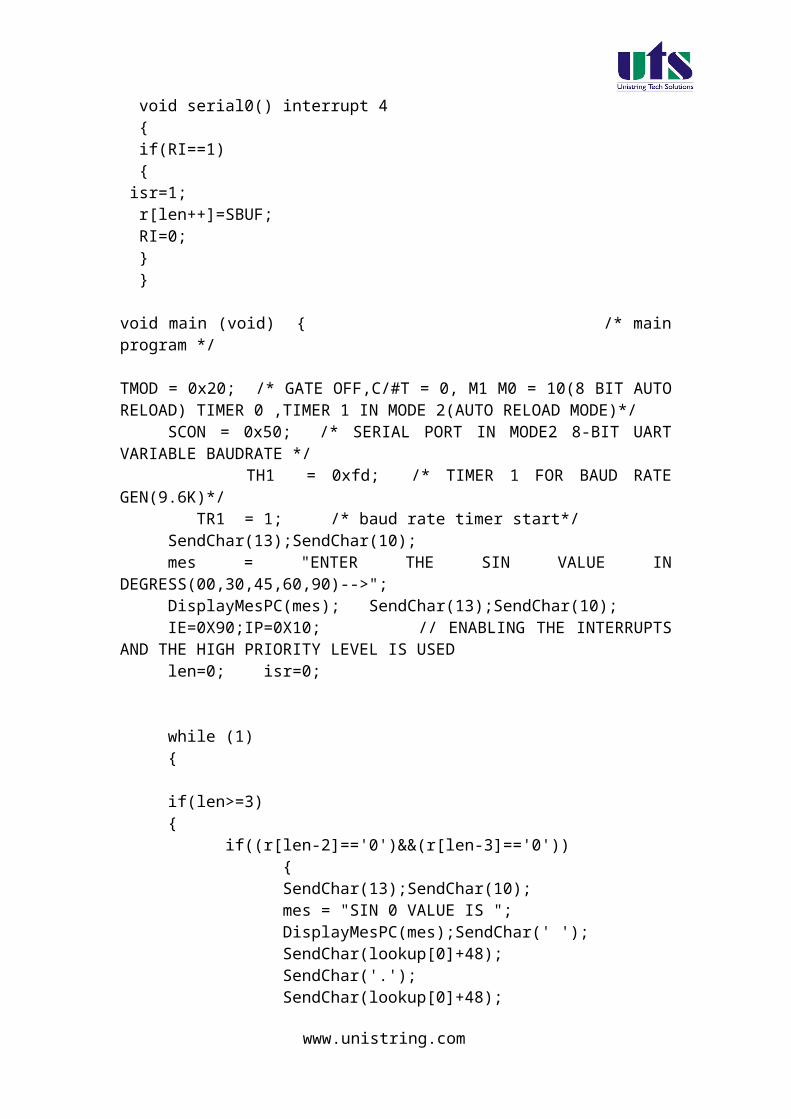
void main (void) { /* main program */ TMOD = 0x20; /* GATE OFF,C/#T = 0, M1 M0 = 10(8 BIT AUTO RELOAD) TIMER 0 ,TIMER 1 IN MODE 2(AUTO RELOAD MODE)*/
SCON = 0x50; /* SERIAL PORT IN MODE2 8-BIT UART VARIABLE BAUDRATE */ TH1 = 0xfd; /* TIMER 1 FOR BAUD RATE GEN(9.6K)*/ TR1 = 1; /* baud rate timer start*/
SendChar(13);SendChar(10);mes = "ENTER THE SIN VALUE IN DEGRESS(00,30,45,60,90)-->";DisplayMesPC(mes); SendChar(13);SendChar(10);IE=0X90;IP=0X10; // ENABLING THE INTERRUPTS AND
THE HIGH PRIORITY LEVEL IS USEDlen=0; isr=0;
while (1) {
if(len>=3){
if((r[len-2]=='0')&&(r[len-3]=='0')) { SendChar(13);SendChar(10); mes = "SIN 0 VALUE IS "; DisplayMesPC(mes);SendChar(' '); SendChar(lookup[0]+48); SendChar('.'); SendChar(lookup[0]+48); isr=0; len=0; SendChar(13); SendChar(10);
www.unistring.com

SendChar(13); SendChar(10); mes = "ENTER THE SIN VALUE IN
DEGRESS(00,30,45,60,90) AND PRESS ENTER-->"; DisplayMesPC(mes);
}
else if((r[len-2]=='0')&&(r[len-3]=='3')) { SendChar(13);SendChar(10); mes = "SIN 30 VALUE IS -->"; DisplayMesPC(mes); SendChar(' '); SendChar(lookup[0]+48); SendChar('.'); SendChar(lookup[5]+48);
isr=0; len=0; SendChar(13); SendChar(10); SendChar(13); SendChar(10); mes = "ENTER THE SIN VALUE IN
DEGRESS(00,30,45,60,90) AND PRESS ENTER-->"; DisplayMesPC(mes);
}
else if((r[len-2]=='5')&&(r[len-3]=='4')) { SendChar(13);
SendChar(10); mes = "SIN 45 VALUE IS -->"; DisplayMesPC(mes); SendChar(' '); SendChar(lookup[0]+48); SendChar('.'); SendChar(lookup[7]+48); SendChar(lookup[0]+48);
isr=0; len=0; SendChar(13); SendChar(10); SendChar(13); SendChar(10); mes = "ENTER THE SIN VALUE IN
DEGRESS(00,30,45,60,90) AND PRESS ENTER-->"; DisplayMesPC(mes);}
else if((r[len-2]=='0')&&(r[len-3]=='6')){ SendChar(13);SendChar(10); mes = "SIN 60 VALUE IS -->";
www.unistring.com
DisplayMesPC(mes); SendChar(' '); SendChar(lookup[0]+48); SendChar('.'); SendChar(lookup[8]+48); SendChar(lookup[6]+48); isr=0; len=0; SendChar(13); SendChar(10); SendChar(13); SendChar(10); mes = "ENTER THE SIN VALUE IN
DEGRESS(00,30,45,60,90) AND PRESS ENTER-->"; DisplayMesPC(mes);
}
else if((r[len-2]=='0')&&(r[len-3]=='9')){ SendChar(13);
SendChar(10); mes = "SIN 90 VALUE IS -->"; DisplayMesPC(mes);SendChar(' '); SendChar(lookup[1]+48); isr=0; len=0; SendChar(13); SendChar(10); SendChar(13); SendChar(10); mes = "ENTER THE SIN VALUE IN
DEGRESS(00,30,45,60,90) AND PRESS ENTER-->"; DisplayMesPC(mes); }else
{ SendChar(13);SendChar(10);
mes = "TRY THE MENTIONED DEGREES"; DisplayMesPC(mes); SendChar(' '); isr=0;len=0; SendChar(13); SendChar(10); SendChar(13); SendChar(10); mes = "ENTER THE SIN VALUE IN
DEGRESS(00,30,45,60,90) AND PRESS ENTER-->"; DisplayMesPC(mes); }
}
www.unistring.com

}
}
void SendChar(unsigned char x) // transmit function to send character to PC{ SBUF =x; // wrting the character into the serial buffer TI = 0; // Clearing the Transmit empty flag while(!TI); // wating for end of trasmission. after transmission the TI flag will set. }
void DisplayMesPC(unsigned char *mes){int counter;for (counter=0;mes[counter]!='\0';counter++) { SendChar(mes[counter]); }}
Results/Discussion:
After programming the code into the microcontroller just reset the microcontroller and put it in the rum mode. You can see the temperature value from the temperature sensor is shown on the lcd and the hyper terminal.
www.unistring.com

HARWARE CONFIGURATION
To test the board
Power supply cable should be connected to the M7 Board and serial cable must be connected to the computer. Now go to the start menu and in that go to the all programs menu . in that go to the accessories , there in the sub menu you will find a menu called communications. In the communications menu select the hyper terminal.
After doing so the following window will be appeared. Enter any connection name in block.
Select COM1 and then click ok
www.unistring.com
In that select the new connection and set the options as restore to defaults.This will keep the default baud rate as 9600,1 start bit,1 stop bit and hardware as none.
www.unistring.com

To check the output now, if any key is pressed from the keyboard that will be displayed on the hyper terminal.
www.unistring.com
3. Timing subroutines for 8051- Real time times and Applications.
Experiment – 3a
Write a program for implementing the real time interrupt generation using timers
Aim: Write a program for implementing the real time interrupt generation using timers
Introduction:
In this experiment a program is written in C language to use the
timer as an interrupt generation and send a character when the
timer is runned out.
The program flow chart Write a program for timer 0 interrupt generation. Compile the program and generate Hex file. The generated hex file will be downloaded in to the MC
and verify the result.
KIEL software is used for compilation of C files and the hex file can be generated. Experimental procedure:
Step1:
Open the kiel ide and you can see a menu as shoen in the figure.
www.unistring.com

Step 2:
To create a new project just click the project menu and click new microvision project , as shown in below figure.
www.unistring.com

Step 3:
Then a dialog box will be opened to give the destination as shown in the figure. You can give the destination folder and save it.
www.unistring.com

Step 4:
To write a c file click the file menu and select the new document. The desired code is written in the document. And this document is needed to be added to the project.
Step 5:
In the project window on the left hand side you can see a project window .in the window a folder called target can be seen to that folder another folder can be seen as target source group1. the c file which is written nedded to be added to that folder . to add a c file to that folder right click the source group1 folder and a menu will be appeared as shown in the figure.
www.unistring.com

From that menu you can see add files to source group option. If you click that option the c file will be added to the project.
Step 6:
Before bulding the project some settings are to made, from the main menu click the flash, you can see the option as configure flash tools . you click that option you can find a menu as shown in the figure.
www.unistring.com

From that menu click output and select an option called create hex file. And in the target menu give the oscillator frequency as 11.0592.
Step 7:
Now all the hard work we have done to build the project and to create the hex file From the main menu select the project and in that an option called build target can be seen , just click that . if all the coding is correct and the syntaxes are correct an hex file will be generated.
Down loading the hex file to the target:
Open the Flash Magic tool for downloading into the Microcontroller Board. Click on Device menu select option you will be popped up with a window named choose device. Under choose device options select 8051 and click on Ok button to open flash magic tool to download the hex file in to the MC and is as shown below.
www.unistring.com
(5) Flash Magic Opens as shown in the figure
Change setting for Flash Magic as shown in the above figureCOM Port Choose the Appropriate COM Port of the computer. Generally it is COM1Baud Rate 9600Device 89V51RD2Interface None(ISP)Oscillator Freq (MHZ) 11.0592Tick Erase All Flash+Security+ClksTick Verify after Programming
Now Goto
Option-> Advanced Options → Hardware Configuration and uncheck the “Use DTR To Control Reset” as shown in the figure below
www.unistring.com

Browse for Hex file to be downloaded into the microcontroller
Select the switches.Hex file from the Folder in which switches.c file is located.
Turn On the Board Power. The RUN/PROG button can be any where (as 89V51RD2)
Connect the serial port to Board from Computer Press and hold the reset button on board and press start
button on flash magic. wait until a small window comes with message "Reset The Device Into ISP Mode "comes.Once this window comes release the reset button.
You can see the messages in flash magic tool as Erasing the Device, Programming the Device ,Verifying and Finished
(10)Once you get finished message in the flash magic. press reset once to enter in run mode.
Results/Output verification: Now serial communication program is running on Microcontroller. Open flash magic tool and under tools menu click on terminal as shown below.
www.unistring.com

A window will be popped up and select the following settings as done in the previous program .
You can observe a black window appearing having two parts. One is output and another one is input to communicate to the serial port. Press reset button and you can see a message saying “press any key” under output pane. Now what ever the message you type at input pane, the same message will be displayed on the output pane.
www.unistring.com
C SOURCE CODE
#include <reg51.h> /* define 8051 registers */
void SendChar(unsigned char );unsigned int count=0;unsigned char usetimer=0,timeout=0;
www.unistring.com

void timer0 (void) interrupt 1 /* for start of conversion at every second*/ {
TR0 = 0; if(usetimer==1) {
count--; if(count==0){ timeout=1;}
} TL0 = 0xFD ; TH0 = 0x4A; TR0 = 1;
}
void main (void) { /* main program */
TMOD = 0x21; TL0 = 0xFD ; TH0 = 0x4A; EA = 1; // Master Enable for Interrupts ET0=1; TR0 = 1;
count=20; usetimer=1; while(1) { if(timeout==1)
{ timeout=0;count=0;usetimer=0; // TMOD = 0x22; /* GATE OFF,C/#T = 0, M1 M0 = 10(8 BIT AUTO RELOAD) TIMER 1 IN MODE 2(AUTO RELOAD MODE)TIMER 0 in 16 bit mode*/ SCON = 0x50; /* SERIAL PORT IN MODE2 8-BIT UART VARIABLE BAUDRATE */ TH1 = 0xfd; /* TIMER 1 FOR BAUD RATE GEN(9.6K)*/ TR1 = 1; /* baud rate timer start*/ SendChar('A'); timeout=0;count=30;usetimer=1;
} }}
www.unistring.com

void SendChar(unsigned char x) // transmit function to send character to PC{ TI = 0; // Clearing the Transmit empty flag SBUF =x; // wrting the character into the serial buffer while(!TI); // wating for end of trasmission. after transmission the TI flag will set. }
HARWARE CONFIGURATION
To test the board
Power supply cable should be connected to the M7 Board and serial cable must be connected to the computer. Now go to the start menu and in that go to the all programs menu . in that go to the accessories , there in the sub menu you will find a menu called communications. In the communications menu select the hyper terminal.
After doing so the following window will be appeared. Enter any connection name in block.
www.unistring.com

Select COM1 and then click ok
www.unistring.com
In that select the new connection and set the options as restore to defaults.This will keep the default baud rate as 9600,1 start bit,1 stop bit and hardware as none.
www.unistring.com

Results/Discussion
After programming the code in the microcontroller, the output can be seen as when the timer is runned out an interrupt is generated by showing a character is sent to the hyper terminal .
8051 Timers:As you already know, the microcontroller oscillator uses quartz crystal for its
operation. As the frequency of this oscillator is precisely defined and very
stable, pulses it generates are always of the same width, which makes them
ideal for time measurement. Such crystals are also used in quartz watches. In
order to measure time between two events it is sufficient to count up pulses
coming from this oscillator. That is exactly what the timer does. If the timer is
properly programmed, the value stored in its register will be incremented (or
decremented) with each coming pulse, i.e. once per each machine cycle. A
single machine-cycle instruction lasts for 12 quartz oscillator periods, which
means that by embedding quartz with oscillator frequency of 12MHz, a
number stored in the timer register will be changed million times per second,
i.e. each microsecond.
The 8051 microcontroller has 2 timers/counters called T0 and T1. As their
names suggest, their main purpose is to measure time and count external
events. Besides, they can be used for generating clock pulses to be used in
serial communication, so called Baud Rate.
Timer T0
As seen in figure below, the timer T0 consists of two registers – TH0 and TL0
representing a low and a high byte of one 16-digit binary number.
www.unistring.com

Accordingly, if the content of the timer T0 is equal to 0 (T0=0) then both
registers it consists of will contain 0. If the timer contains for example number
1000 (decimal), then the TH0 register (high byte) will contain the number 3,
while the TL0 register (low byte) will contain decimal number 232.
Formula used to calculate values in these two registers is very simple:
TH0 × 256 + TL0 = T
Matching the previous example it would be as follows:
3 × 256 + 232 = 1000
Since the timer T0 is virtually 16-bit register, the largest value it can store is
65 535. In case of exceeding this value, the timer will be automatically cleared
and counting starts from 0. This condition is called an overflow. Two registers
TMOD and TCON are closely connected to this timer and control its
operation.
TMOD Register (Timer Mode)
The TMOD register selects the operational mode of the timers T0 and T1. As
seen in figure below, the low 4 bits (bit0 - bit3) refer to the timer 0, while the
high 4 bits (bit4 - bit7) refer to the timer 1. There are 4 operational modes and
each of them is described herein.
www.unistring.com

Bits of this register have the following function:
GATE1 enables and disables Timer 1 by means of a signal brought to the
INT1 pin (P3.3):
1 - Timer 1 operates only if the INT1 bit is set.
0 - Timer 1 operates regardless of the logic state of the INT1 bit.
C/T1 selects pulses to be counted up by the timer/counter 1:
1 - Timer counts pulses brought to the T1 pin (P3.5).
0 - Timer counts pulses from internal oscillator.
T1M1,T1M0 These two bits select the operational mode of the Timer 1.
T1M1 T1M0 Mode Description
0 0 0 13-bit timer
0 1 1 16-bit timer
1 0 2 8-bit auto-reload
1 1 3 Split mode
GATE0 enables and disables Timer 1 using a signal brought to the INT0 pin
(P3.2):
1 - Timer 0 operates only if the INT0 bit is set.
0 - Timer 0 operates regardless of the logic state of the INT0 bit.
C/T0 selects pulses to be counted up by the timer/counter 0:
1 - Timer counts pulses brought to the T0 pin (P3.4).
0 - Timer counts pulses from internal oscillator.
T0M1,T0M0 These two bits select the oprtaional mode of the Timer 0.
T0M1 T0M0 Mode Description
0 0 0 13-bit timer
0 1 1 16-bit timer
1 0 2 8-bit auto-reload
1 1 3 Split mode
Timer 0 in mode 0 (13-bit timer)
This is one of the rarities being kept only for the purpose of compatibility with
the previuos versions of microcontrollers. This mode configures timer 0 as a
13-bit timer which consists of all 8 bits of TH0 and the lower 5 bits of TL0. As
a result, the Timer 0 uses only 13 of 16 bits. How does it operate? Each
coming pulse causes the lower register bits to change their states. After
www.unistring.com

receiving 32 pulses, this register is loaded and automatically cleared, while
the higher byte (TH0) is incremented by 1. This process is repeated until
registers count up 8192 pulses. After that, both registers are cleared and
counting starts from 0.
Timer 0 in mode 1 (16-bit timer)
Mode 1 configures timer 0 as a 16-bit timer comprising all the bits of both
registers TH0 and TL0. That's why this is one of the most commonly used
modes. Timer operates in the same way as in mode 0, with difference that the
registers count up to 65 536 as allowable by the 16 bits.
www.unistring.com
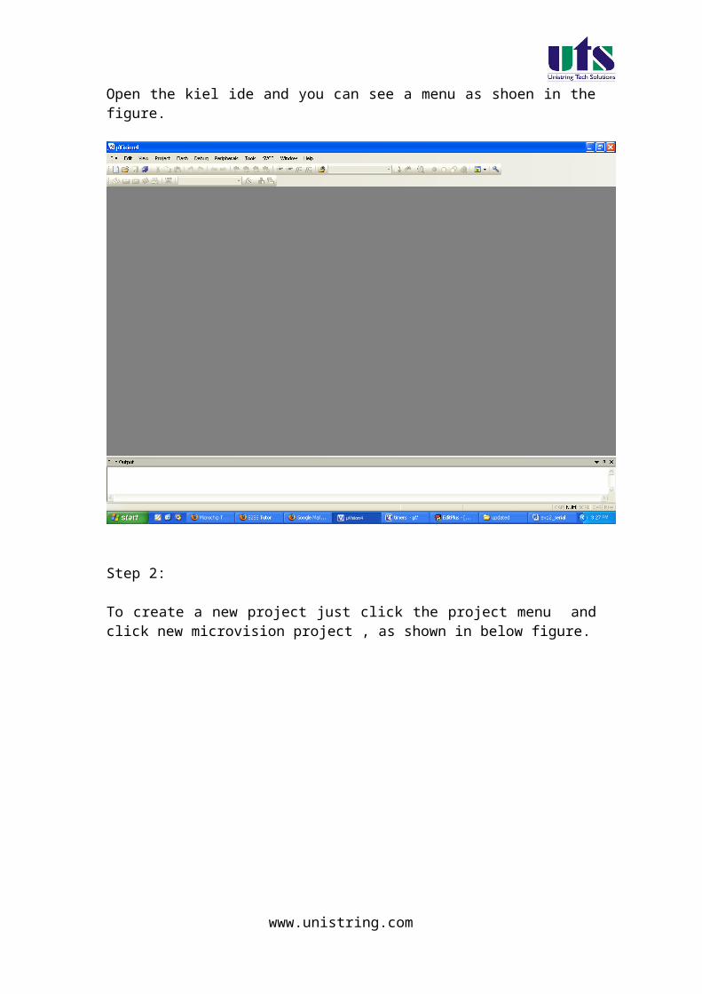
Timer 0 in mode 2 (Auto-Reload Timer)
Mode 2 configures timer 0 as an 8-bit timer. Actually, timer 0 uses only one 8-
bit register for counting and never counts from 0, but from an arbitrary value
(0-255) stored in another (TH0) register.
The following example shows the advantages of this mode. Suppose it is
necessary to constantly count up 55 pulses generated by the clock.
If mode 1 or mode 0 is used, It is necessary to write the number 200 to the
timer registers and constantly check whether an overflow has occurred, i.e.
whether they reached the value 255. When it happens, it is necessary to
rewrite the number 200 and repeat the whole procedure. The same procedure
is automatically performed by the microcontroller if set in mode 2. In fact, only
the TL0 register operates as a timer, while another (TH0) register stores the
value from which the counting starts. When the TL0 register is loaded, instead
of being cleared, the contents of TH0 will be reloaded to it. Referring to the
previous example, in order to register each 55th pulse, the best solution is to
write the number 200 to the TH0 register and configure the timer to operate in
mode 2.
www.unistring.com

Timer 0 in Mode 3 (Split Timer)
Mode 3 configures timer 0 so that registers TL0 and TH0 operate as separate
8-bit timers. In other words, the 16-bit timer consisting of two registers TH0
and TL0 is split into two independent 8-bit timers. This mode is provided for
applications requiring an additional 8-bit timer or counter. The TL0 timer turns
into timer 0, while the TH0 timer turns into timer 1. In addition, all the control
bits of 16-bit Timer 1 (consisting of the TH1 and TL1 register), now control the
8-bit Timer 1. Even though the 16-bit Timer 1 can still be configured to
operate in any of modes (mode 1, 2 or 3), it is no longer possible to disable it
as there is no control bit to do it. Thus, its operation is restricted when timer 0
is in mode 3.
www.unistring.com

The only application of this mode is when two timers are used and the 16-bit
Timer 1 the operation of which is out of control is used as a baud rate
generator.
Timer Control (TCON) Register
TCON register is also one of the registers whose bits are directly in control of
timer operation.
Only 4 bits of this register are used for this purpose, while rest of them is used
for interrupt control to be discussed later.
TF1 bit is automatically set on the Timer 1 overflow.
TR1 bit enables the Timer 1.
1 - Timer 1 is enabled.
0 - Timer 1 is disabled.
TF0 bit is automatically set on the Timer 0 overflow.
TR0 bit enables the timer 0.
1 - Timer 0 is enabled.
www.unistring.com

0 - Timer 0 is disabled.
How to use the Timer 0 ?
In order to use timer 0, it is first necessary to select it and configure the mode
of its operation. Bits of the TMOD register are in control of it:
Referring to figure above, the timer 0 operates in mode 1 and counts pulses
generated by internal clock the frequency of which is equal to 1/12 the quartz
frequency.
Turn on the timer:
The TR0 bit is set and the timer starts operation. If the quartz crystal with
frequency of 12MHz is embedded then its contents will be incremented every
microsecond. After 65.536 microseconds, the both registers the timer consists
of will be loaded. The microcontroller automatically clears them and the timer
www.unistring.com

keeps on repeating procedure from the beginning until the TR0 bit value is
logic zero (0).
How to 'read' a timer?
Depending on application, it is necessary either to read a number stored in
the timer registers or to register the moment they have been cleared.
- It is extremely simple to read a timer by using only one register configured in
mode 2 or 3. It is sufficient to read its state at any moment. That's all!
- It is somehow complicated to read a timer configured to operate in mode 2.
Suppose the lower byte is read first (TL0), then the higher byte (TH0). The
result is:
TH0 = 15 TL0 = 255
Everything seems to be ok, but the current state of the register at the moment
of reading was:
TH0 = 14 TL0 = 255
In case of negligence, such an error in counting (255 pulses) may occur for
not so obvious but quite logical reason. The lower byte is correctly read (255),
but at the moment the program counter was about to read the higher byte
TH0, an overflow occurred and the contents of both registers have been
changed (TH0: 14→15, TL0: 255→0). This problem has a simple solution.
The higher byte should be read first, then the lower byte and once again the
higher byte. If the number stored in the higher byte is different then this
sequence should be repeated. It's about a short loop consisting of only 3
instructions in the program.
There is another solution as well. It is sufficient to simply turn the timer off
while reading is going on (the TR0 bit of the TCON register should be
cleared), and turn it on again after reading is finished.
Timer 0 Overflow Detection
Usually, there is no need to constantly read timer registers. It is sufficient to
register the moment they are cleared, i.e. when counting starts from 0. This
condition is called an overflow. When it occurrs, the TF0 bit of the TCON
register will be automatically set. The state of this bit can be constantly
checked from within the program or by enabling an interrupt which will stop
the main program execution when this bit is set. Suppose it is necessary to
www.unistring.com
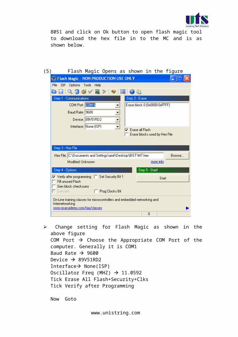
provide a program delay of 0.05 seconds (50 000 machine cycles), i.e. time
when the program seems to be stopped:
First a number to be written to the timer registers should be calculated:
Then it should be written to the timer registers TH0 and TL0:
When enabled, the timer will resume counting from this number. The state of
the TF0 bit, i.e. whether it is set, is checked from within the program. It
happens at the moment of overflow, i.e. after exactly 50.000 machine cycles
or 0.05 seconds.
How to measure pulse duration?
www.unistring.com

Suppose it is necessary to measure the duration of an operation, for example
how long a device has been turned on? Look again at the figure illustrating
the timer and pay attention to the function of the GATE0 bit of the TMOD
register. If it is cleared then the state of the P3.2 pin doesn't affect timer
operation. If GATE0 = 1 the timer will operate until the pin P3.2 is cleared.
Accordingly, if this pin is supplied with 5V through some external switch at the
moment the device is being turned on, the timer will measure duration of its
operation, which actually was the objective.
How to count up pulses?
Similarly to the previous example, the answer to this question again lies in the
TCON register. This time it's about the C/T0 bit. If the bit is cleared the timer
counts pulses generated by the internal oscillator, i.e. measures the time
passed. If the bit is set, the timer input is provided with pulses from the P3.4
pin (T0). Since these pulses are not always of the same width, the timer
cannot be used for time measurement and is turned into a counter, therefore.
The highest frequency that could be measured by such a counter is 1/24
frequency of used quartz-crystal.
Timer 1
www.unistring.com

Timer 1 is identical to timer 0, except for mode 3 which is a hold-count mode.
It means that they have the same function, their operation is controlled by the
same registers TMOD and TCON and both of them can operate in one out of
4 different modes.
www.unistring.com
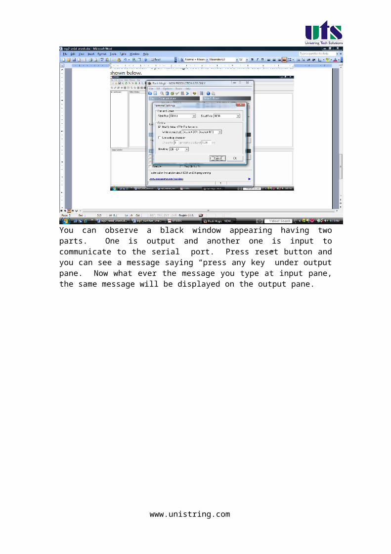
Experiment – 3b
Write a program for implementing timer as a delay generator
Aim: Write a program for implementing the timer as a required various delay generator.
Introduction:
In this experiment a program is written in C language to use the
timer as an different delay generator.
The program flow chart Write a program for timer 0 which is used as a delay
generator. Compile the program and generate Hex file. The generated hex file will be downloaded in to the MC
and verify the result.
KIEL software is used for compilation of C files and the hex file can be generated. Experimental procedure:
Step1:
Open the kiel ide and you can see a menu as shoen in the figure.
www.unistring.com

Step 2:
To create a new project just click the project menu and click new microvision project , as shown in below figure.
www.unistring.com

Step 3:
Then a dialog box will be opened to give the destination as shown in the figure. You can give the destination folder and save it.
www.unistring.com

Step 4:
To write a c file click the file menu and select the new document. The desired code is written in the document. And this document is needed to be added to the project.
Step 5:
In the project window on the left hand side you can see a project window .in the window a folder called target can be seen to that folder another folder can be seen as target source group1. the c file which is written nedded to be added to that folder . to add a c file to that folder right click the source group1 folder and a menu will be appeared as shown in the figure.
www.unistring.com
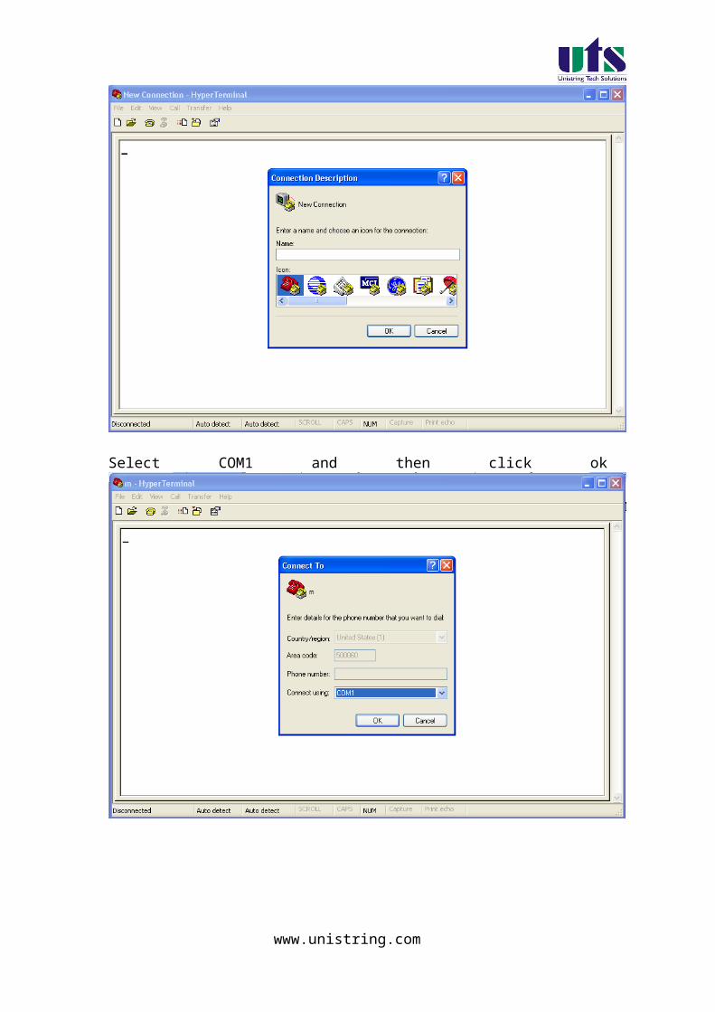
From that menu you can see add files to source group option. If you click that option the c file will be added to the project.
Step 6:
Before bulding the project some settings are to made, from the main menu click the flash, you can see the option as configure flash tools . you click that option you can find a menu as shown in the figure.
www.unistring.com

From that menu click output and select an option called create hex file. And in the target menu give the oscillator frequency as 11.0592.
Step 7:
Now all the hard work we have done to build the project and to create the hex file From the main menu select the project and in that an option called build target can be seen , just click that . if all the coding is correct and the syntaxes are correct an hex file will be generated.
Down loading the hex file to the target:
Open the Flash Magic tool for downloading into the Microcontroller Board. Click on Device menu select option you will be popped up with a window named choose device. Under choose device options select 8051 and click on Ok button to open flash magic tool to download the hex file in to the MC and is as shown below.
www.unistring.com

(6) Flash Magic Opens as shown in the figure
Change setting for Flash Magic as shown in the above figureCOM Port Choose the Appropriate COM Port of the computer. Generally it is COM1Baud Rate 9600Device 89V51RD2Interface None(ISP)Oscillator Freq (MHZ) 11.0592Tick Erase All Flash+Security+ClksTick Verify after Programming
Now Goto
Option-> Advanced Options → Hardware Configuration and uncheck the “Use DTR To Control Reset” as shown in the figure below
www.unistring.com

Browse for Hex file to be downloaded into the microcontroller
Select the switches.Hex file from the Folder in which switches.c file is located.
Turn On the Board Power. The RUN/PROG button can be any where (as 89V51RD2)
Connect the serial port to Board from Computer Press and hold the reset button on board and press start
button on flash magic. wait until a small window comes with message "Reset The Device Into ISP Mode "comes.Once this window comes release the reset button.
You can see the messages in flash magic tool as Erasing the Device, Programming the Device ,Verifying and Finished
(10)Once you get finished message in the flash magic. press reset once to enter in run mode.
Results/Output verification: Now serial communication program is running on Microcontroller. Open flash magic tool and under tools menu click on terminal as shown below.
www.unistring.com

A window will be popped up and select the following settings as done in the previous program .
You can observe a black window appearing having two parts. One is output and another one is input to communicate to the serial port. Press reset button and you can see a message saying “press any key” under output pane. Now what ever the message you type at input pane, the same message will be displayed on the output pane.
www.unistring.com

C SOURCE CODE
#include <reg51.h> /* define 8051 registers */
void SendChar(unsigned char );void Send_Hex(unsigned char );void DisplayMesPC(unsigned char *);unsigned char *mes;
www.unistring.com

unsigned int count=0,count1=1;unsigned char temp=0,temp1=0; void main (void) { /* main program */
TMOD = 0x21; TL0 = 0x00 ; TH0 = 0x00; SCON = 0x50; /* SERIAL PORT IN MODE2 8-BIT UART VARIABLE BAUDRATE */ TH1 = 0xfd; /* TIMER 1 FOR BAUD RATE GEN(9.6K)*/ TR1 = 1; /* baud rate timer start*/ ET0=1;
TR0 = 0; mes = "\r\n\r\nProgram delay measurement using timers on 8051\r\n"; DisplayMesPC(mes);
while(count1<=7) { TL0 = 0x00 ; TH0 = 0x00; mes = "\r\n\r\n\r\nThe Default Timer Register values\r\n"; DisplayMesPC(mes); mes = "\r\nTH0 | TL0 ="; DisplayMesPC(mes);
temp=TL0; temp1=TH0; Send_Hex(temp1); Send_Hex(temp); mes = "\r\n\r\nThe Programing is running....\r\n"; DisplayMesPC(mes); TR0 =1;
while(count<count1){ SendChar('S'); count++; }
TR0 = 0; mes = "\r\n\r\nAfter Running program Timer Register values\r\n"; DisplayMesPC(mes); mes = "\r\nTH0 | TL0 ="; DisplayMesPC(mes);
temp=TL0;
www.unistring.com

temp1=TH0; Send_Hex(temp1); Send_Hex(temp);
count=0; count1++; } while(1); }
void SendChar(unsigned char x) // transmit function to send character to PC{ TI = 0; // Clearing the Transmit empty flag SBUF =x; // wrting the character into the serial buffer while(!TI); // wating for end of trasmission. after transmission the TI flag will set. }
void DisplayMesPC(unsigned char *mes){int counter;for (counter=0;mes[counter]!='\0';counter++) { SendChar(mes[counter]); }}
void Send_Hex(unsigned char i){ char low,high; low=i&0x0f; high=(i&0xf0)>>4;
if( high>9) SendChar(high+55); else SendChar(high+48); if( low>9) SendChar(low+55); else SendChar(low+48); }
www.unistring.com

HARWARE CONFIGURATION
To test the board
Power supply cable should be connected to the M7 Board and serial cable must be connected to the computer. Now go to the start menu and in that go to the all programs menu . in that go to the accessories , there in the sub menu you will find a menu called communications. In the communications menu select the hyper terminal.
After doing so the following window will be appeared. Enter any connection name in block.
Select COM1 and then click ok
www.unistring.com

In that select the new connection and set the options as restore to defaults.This will keep the default baud rate as 9600,1 start bit,1 stop bit and hardware as none.
www.unistring.com
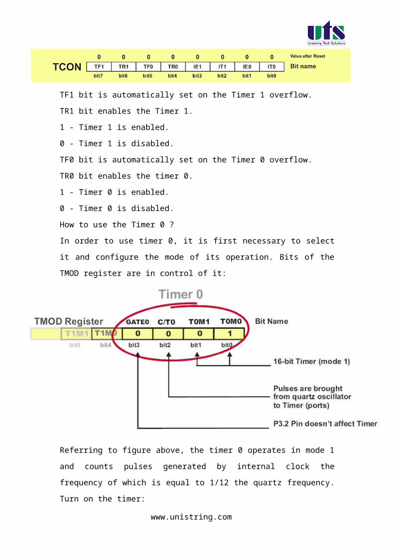
Results/Discussion
After programming the code in the microcontroller, the output can be seen as when the value in the count is passed say 1 for 1 sec and 2 for2 seconds .then the timer will work accordingly .so for according to passing the value for the timer ,a character is sent for 1 second or 2 second and so on and the output will be sent to the hyper terminal.
www.unistring.com

4. Keyboard interface to 8051.
Experiment – 4a
Write a program for interfacing a keypad to the microcontroller
Aim: Write a program for interfacing a keypad to the microcontroller and the output is shown in the seven segment display when ever a key is pressed.
Introduction:
In this experiment a program is written in C language to read data from the keypad
and the data is sent to the seven segment display on the board.
The program flow chart Write a program for interfacing keypad and the output is shown in the
seven segment display when ever a key is pressed. Compile the program and generate Hex file. The generated hex file will be downloaded in to the MC and verify the
result.
KIEL software is used for compilation of C files and the hex file can be generated. Experimental procedure:
Step1:
Open the kiel ide and you can see a menu as shown in the figure.
www.unistring.com
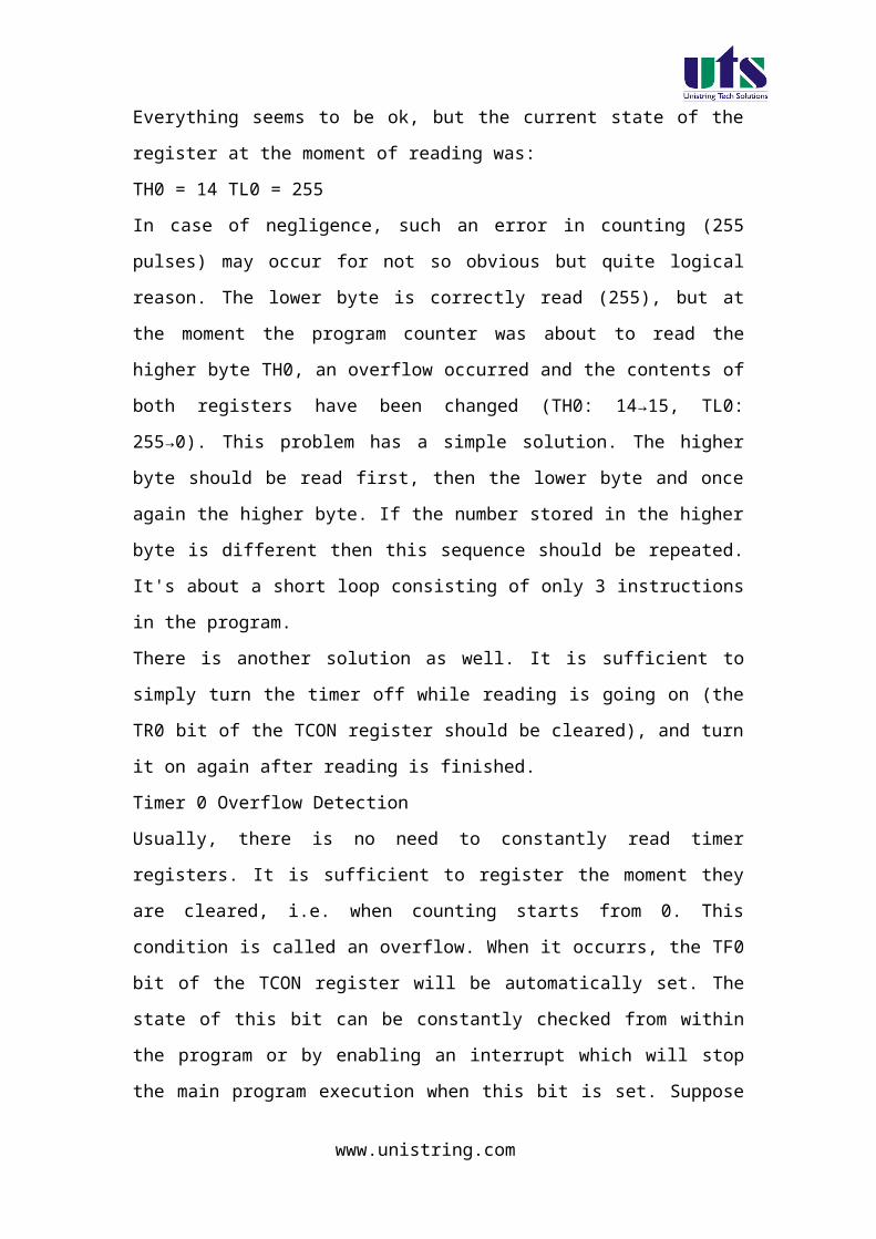
Step 2:
To create a new project just click the project menu and click new microvision project , as shown in below figure.
www.unistring.com
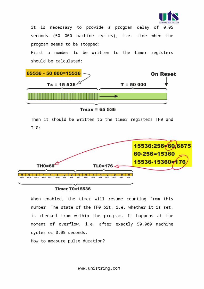
Step 3:
Then a dialog box will be opened to give the destination as shown in the figure. You can give the destination folder and save it.
www.unistring.com

Step 4:
To write a c file click the file menu and select the new document. The desired code is written in the document. And this document is needed to be added to the project.
Step 5:
In the project window on the left hand side you can see a project window .in the window a folder called target can be seen to that folder another folder can be seen as target source group1. the c file which is written nedded to be added to that folder . to add a c file to that folder right click the source group1 folder and a menu will be appeared as shown in the figure.
www.unistring.com

From that menu you can see add files to source group option. If you click that option the c file will be added to the project.
Step 6:
Before bulding the project some settings are to made, from the main menu click the flash, you can see the option as configure flash tools . you click that option you can find a menu as shown in the figure.
www.unistring.com

From that menu click output and select an option called create hex file. And in the target menu give the oscillator frequency as 11.0592.
Step 7:
Now all the hard work we have done to build the project and to create the hex file From the main menu select the project and in that an option called build target can be seen , just click that . if all the coding is correct and the syntaxes are correct an hex file will be generated.
Down loading the hex file to the target:
Follow the same steps as mentioned in Ex 1-a for downloading the hex file into the microcontroller
www.unistring.com

C SOURCE CODE
#include <reg51.h>#include"lcd.h" sbit R1 = P1^0; sbit R2 = P1^1; sbit R3 = P1^2;sbit R4 = P1^3;sbit C1 = P1^4;sbit C2 = P1^5;sbit C3 = P1^6;sbit C4 = P1^7; unsigned char key;void Delay(unsigned int);void delay(){
unsigned int i;
for (i=0; i<10; i++); /* For 1 ms */
}
unsigned char READ_SWITCHES (void) // initialize the port for inputs
{ // P1.0 to p1.3 are outpot; and P1.4 to P1.7 are inputs
// the keybad is connected to port 1R4=1; // make all rows = 1R3=1;R2=1;R1=0;
//test row 1
if (C1 == 0){ // key 1 is presed delay(); //depounce while (C1==0); //wait until release the key
return 1; //}
if (C2 == 0){ //key 2 is pressed delay(); //depounce
while (C2==0); //wait until release the key
www.unistring.com

return 2; }
if (C3 == 0){ //key 3 is pressed delay(); //depounce
while (C3==0); //wait until release the key return 3;}
if (C4 == 0){ //key 4 is pressed delay(); //depounce while (C4==0); //wait until release the key
return 4;}
//test row 2R4=1;R3=1;R1=1;R2=0;
if (C1 == 0){ //key 5 is pressed delay(); //depounce
while (C1==0); //wait until release the key return 5;
}
if (C2 == 0) { //key 6 is pressed delay(); //depounce
while (C2==0); //wait until release the key return 6;
}
if (C3 == 0){ //key 6 is pressed delay(); //depounce
while (C3==0); //wait until release the keyreturn 7;
}
if (C4 == 0) { //key 7 is pressed delay(); //depounce
while (C4==0); //wait until release the key
return 8;}
//test row 3R4=1;R1=1;R2=1;
www.unistring.com

R3=0;
if (C1 == 0) { //key 8 is pressed delay(); //depouncewhile (C1==0); //wait until release the key
return 9;
}
if (C2 == 0) { //key 9 is presseddelay(); //depouncewhile (C2==0); //wait until release the key
return 10;
}if (C3 == 0) { //key A is pressed
delay(); //depouncewhile (C3==0); //wait until release the key
return 11;}
if (C4 == 0) { //key B is presseddelay(); //depouncewhile (C4==0); //wait until release the keyreturn 12;
}
//test row 4R1=1;R2=1;R3=1;R4=0;
if (C1 == 0) { //key C is presseddelay(); //depouncewhile (C1==0); //wait until release the key return 13;
}if (C2 == 0){ //key D is pressed
delay(); //depouncewhile (C2==0); //wait until release the key
return 14;
}
if (C3 == 0){ //key E is presseddelay(); //depouncewhile (C3==0); //wait until release the key
www.unistring.com

return 15;}if (C4 == 0) { //key C is pressed
delay(); //depouncewhile (C4==0); //wait until release the keyreturn 16;
}
return 0; // Means no key has been pressed}
void main (void) { P1 =0xf0;
P3=0x00; LCD_init(); LCD_row1(); LCD_puts("< SERIAL KEYPAD >"); LCD_row2(); LCD_puts(" INTERFACING "); Delay(3); LCD_clear(); LCD_row1(); LCD_puts("< SERIAL KEYPAD >");
LCD_row2(); LCD_puts("KEY : ");
while(1){
key=READ_SWITCHES();
if(key){ P3 = key-1; LCD_clear();
LCD_row1(); LCD_puts("< SERIAL KEYPAD >");
LCD_row2(); LCD_puts("KEY : ");
switch(key) {
case 1: {
LCD_putc('0');break;
}
www.unistring.com

case 2:{
LCD_putc('1'); break;
}
case 3: {
LCD_putc('2'); break;
}
case 4:{
LCD_putc('3'); break;
} case 5:
{LCD_putc('4'); break;
}
case 6:{
LCD_putc('5'); break;
}
case 7:{
LCD_putc('6'); break;
}
case 8:{
LCD_putc('7'); break;
}
case 9:{
LCD_putc('8'); break;
}
case 10:{
www.unistring.com

LCD_putc('9'); break;
}
case 11:{
LCD_putc('A'); break;
}
case 12:{
LCD_putc('B'); break;
}
case 13:{
LCD_putc('C'); break;
}
case 14:{
LCD_putc('D'); break;
}
case 15:{
LCD_putc('E'); break;
}
case 16:{
LCD_putc('F'); break;
}
}// switch
}//if
}//while
}//main
www.unistring.com

void Delay(unsigned int duration) { unsigned int r2; for (r2 = 0; r2<= duration;r2++){
LCD_delay(250);LCD_delay(250);
} }
/* * Filename : lcd.h * Hardware : Controller -> P89V51RD2 * XTAL -> 11.0592 MHz * * I/O : RS -> P2.5 * Enable -> P2.4 * Data4567 -> P2.0,P2.1,P2.2,P2.3 */
#define LCD_DELAY 150 /* Delay for 1 ms */ #define LCD_clear() LCD_command(0x1) /* Clear display LCD */ #define LCD_origin() LCD_command(0x2) /* Set to origin LCD */ #define LCD_row1() LCD_command(0x80) /* Begin at Line 1 */ #define LCD_row2() LCD_command(0xC0) /* Begin at Line 2 */
/*************************************************** * Prototype(s) * ***************************************************/sbit LCD_en=P2^4;sbit LCD_rs=P2^5;void LCD_delay(unsigned char ms);void LCD_enable();void LCD_command(unsigned char command);void LCD_putc(unsigned char ascii);void LCD_puts(unsigned char *lcd_string);void LCD_init();
/*************************************************** * Sources * ***************************************************/void LCD_delay(unsigned char ms){
www.unistring.com

unsigned char n;unsigned int i;for (n=0; n<ms; n++){
for (i=0; i<LCD_DELAY; i++); /* For 1 ms */}
}
void LCD_enable(){ LCD_en = 0; /* Clear bit P2.4 */ LCD_delay(1); LCD_en = 1; /* Set bit P2.4 */}
void LCD_command(unsigned char command){ LCD_rs = 0; /* Clear bit P2.5 */ P2 = (P2 & 0xF0)|((command>>4) & 0x0F); LCD_enable(); P2 = (P2 & 0xF0)|(command & 0x0F); LCD_enable(); LCD_delay(1);}
void LCD_putc(unsigned char ascii){ LCD_rs = 1; /* Set bit P2.5 */ P2 = (P2 & 0xF0)|((ascii>>4) & 0x0F); LCD_enable(); P2 = (P2 & 0xF0)|(ascii & 0x0F); LCD_enable(); LCD_delay(1);}
void LCD_puts(unsigned char *lcd_string){
while (*lcd_string) {
LCD_putc(*lcd_string++);}
}
void LCD_init(){ LCD_en = 1; /* Set bit P2.4 */ LCD_rs = 0; /* Clear bit P2.5 */ LCD_command(0x28);
LCD_delay(2);
www.unistring.com

LCD_command(0x0C);LCD_delay(2);
LCD_command(0x06);LCD_delay(2);
LCD_command(0x01); /* Clear */ LCD_delay(256);}
Results/Discussion:
After programming the code into the microcontroller just reset the microcontroller and put it in the run mode. You can see what ever key is pressed the corresponding value of that button will be displayed in the LCD Display and LED’s on the board.
HARWARE CONFIGURATIONTo test the board
Connect the keypad to the header (CN6) and P1 using the 8 wire
bus.
Note the P1 (Pin number 1 of the microcontroller) is
connected to R1 of the keypad connector.
For LCD is connected port P2
RS -> P2.5
Enable -> P2.4
Data4567 -> P2.0, P2.1,P2.2, P2.3
5. ADC, DAC interface to 8051.
Experiment – 5a
www.unistring.com

Write a program for interfacing a keypad to the microcontroller
Aim: Write a program for interfacing a keypad to the microcontroller.
Introduction:
In this experiment a program is written in C language to read data from the keypad
and data is sent to the seven segment display to the computer through RS232 interface
available on the board.
The program flow chart Write a program for interfacing adc and collecting the sampled value
and showing on the hyper terminal. Compile the program and generate Hex file. The generated hex file will be downloaded in to the MC and verify the
result.
KIEL software is used for compilation of C files and the hex file can be generated. Experimental procedure:
Step1:
Open the kiel ide and you can see a menu as shoen in the figure.
www.unistring.com

Step 2:
To create a new project just click the project menu and click new microvision project , as shown in below figure.
www.unistring.com

Step 3:
Then a dialog box will be opened to give the destination as shown in the figure. You can give the destination folder and save it.
www.unistring.com

Step 4:
To write a c file click the file menu and select the new document. The desired code is written in the document. And this document is needed to be added to the project.
Step 5:
In the project window on the left hand side you can see a project window .in the window a folder called target can be seen to that folder another folder can be seen as target source group1. the c file which is written nedded to be added to that folder . to add a c file to that folder right click the source group1 folder and a menu will be appeared as shown in the figure.
www.unistring.com

From that menu you can see add files to source group option. If you click that option the c file will be added to the project.
Step 6:
Before bulding the project some settings are to made, from the main menu click the flash, you can see the option as configure flash tools . you click that option you can find a menu as shown in the figure.
www.unistring.com

From that menu click output and select an option called create hex file. And in the target menu give the oscillator frequency as 11.0592.
Step 7:
Now all the hard work we have done to build the project and to create the hex file From the main menu select the project and in that an option called build target can be seen , just click that . if all the coding is correct and the syntaxes are correct an hex file will be generated.
Down loading the hex file to the target:
Open the Flash Magic tool for downloading into the Microcontroller Board. Click on Device menu select option you will be popped up with a window named choose device. Under choose device options select 8051 and click on Ok button to open flash magic tool to download the hex file in to the MC and is as shown below.
(7) Flash Magic Opens as shown in the figure
www.unistring.com

Change setting for Flash Magic as shown in the above figureCOM Port Choose the Appropriate COM Port of the computer. Generally it is COM1Baud Rate 9600Device 89V51RD2Interface None(ISP)Oscillator Freq (MHZ) 11.0592Tick Erase All Flash+Security+ClksTick Verify after Programming
Now Goto
Option-> Advanced Options → Hardware Configuration and uncheck the “Use DTR To Control Reset” as shown in the figure below
www.unistring.com

Browse for Hex file to be downloaded into the microcontroller
Select the switches.Hex file from the Folder in which switches.c file is located.
Turn On the Board Power. The RUN/PROG button can be any where (as 89V51RD2)
Connect the serial port to Board from Computer Press and hold the reset button on board and press start button on flash magic.
wait until a small window comes with message "Reset The Device Into ISP Mode "comes.Once this window comes release the reset button.
You can see the messages in flash magic tool as Erasing the Device, Programming the Device ,Verifying and Finished
(10)Once you get finished message in the flash magic. press reset once to enter in run mode.
Results/Output verification: Now serial communication program is running on Microcontroller. Open flash magic tool and under tools menu click on terminal as shown below.
www.unistring.com

A window will be popped up and select the following settings as done in the previous program .
C SOURCE CODE
#include <reg51.h> /* define 89C52 registers */#include"lcd.h"
sbit rd=P1^0; //Read signal P1.0sbit wr=P1^1; //Write signal P1.1sbit intr=P1^2; //INTR signal P1.3
void conv(); //Start of conversion functionvoid read(); //Read ADC functionvoid display(); void Delay(int a);
unsigned char adc_val;unsigned int value,temp,temp1,temp2,temp3;
void Delay(int a){char i; for(i=0;i<a;i++) { LCD_delay(250); LCD_delay(250);
www.unistring.com

}
}
void main(){ P0=0xFF;
P3=0X00;P1=0x04;
LCD_init();
while(1){ LCD_clear();LCD_row1();LCD_puts("ADC804 INTERFACE");
conv(); //Start conversion read(); //Read ADC P3 = adc_val; //Send the read value to P3
display(); Delay(4);
}}
void conv(){ wr = 0; //Make WR low wr = 1; //Make WR high while(intr); //Wait for INTR to go low}
void read(){ rd = 0; //Make RD low adc_val = P0; //Read ADC port rd = 1; //Make RD high }void display(){ // display the adc vvalue in the form of milli volts
LCD_row2(); LCD_puts("VOLTAGE:");
value=adc_val*19;
if(value>=1000){temp=value/1000;
www.unistring.com

adc_val=temp+48;LCD_putc(adc_val);}
temp1=value%1000;if(temp1>=100&&temp1<=999){temp=temp1;temp=temp/100;adc_val=temp+48;LCD_putc(adc_val);}else
LCD_putc('0');
temp2=temp1%100; if(temp2>=10&&temp<=99){
temp=temp2;temp=temp/10;adc_val=temp+48;LCD_putc(adc_val);}elseLCD_putc('0');
temp3=temp2%10; if(temp3>0&&temp3<10){
temp=temp3;adc_val=temp+48;LCD_putc(adc_val);}else
LCD_putc('0'); LCD_putc(' ');
LCD_putc('m');LCD_putc('v');
}
HARWARE CONFIGURATION
To test the board
Power supply cable should be connected to the M7.1 Board and serial cable must be
connected to the computer.
www.unistring.com
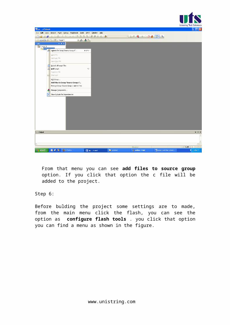
The Data line of the ADC is connected to the P0 of microcontroller.
P0 pin number 0 should be connected D0 of the ADC.
The RD, WR, INTR signals are connected to the P1.0, P1.1, P1.2 respectively.
The VREF signal is connected to the +5V supply of the board.
The P3 is connected to LED PORT (CN4).
The ADC voltage is displayed in LCD, the digital value is shown in LED PORT.
For LCD is connected port P2
RS -> P2.5
Enable -> P2.4
Data4567 -> P2.0, P2.1,P2.2, P2.3
www.unistring.com

Experiment – 5b
Write a program for generating a sine wave using DAC
Aim: Write a program for generating a sine wave using DAC and SIN look up tables.
Introduction:
In this experiment a program is written in C language to generate a
sin wave using dac and sine look up table.
The program flow chart
i) Write a program for generating a sine wave using DAC and SIN look up tables. Compile the program and generate Hex file. The generated hex file will be downloaded in to the MC
and verify the result.
KIEL software is used for compilation of C files and the hex file can be generated.
www.unistring.com

Experimental procedure:
Step1:
Open the kiel ide and you can see a menu as shown in the figure.
Step 2:
To create a new project just click the project menu and click new microvision project , as shown in below figure.
www.unistring.com

Step 3:
Then a dialog box will be opened to give the destination as shown in the figure. You can give the destination folder and save it.
www.unistring.com

Step 4:
To write a c file click the file menu and select the new document. The desired code is written in the document. And this document is needed to be added to the project.
Step 5:
In the project window on the left hand side you can see a project window .in the window a folder called target can be seen to that folder another folder can be seen as target source group1. the c file which is written nedded to be added to that folder . to add a c file to that folder right click the source group1 folder and a menu will be appeared as shown in the figure.
www.unistring.com
From that menu you can see add files to source group option. If you click that option the c file will be added to the project.
Step 6:
Before bulding the project some settings are to made, from the main menu click the flash, you can see the option as configure flash tools . you click that option you can find a menu as shown in the figure.
www.unistring.com

From that menu click output and select an option called create hex file. And in the target menu give the oscillator frequency as 11.0592.
Step 7:
Now all the hard work we have done to build the project and to create the hex file From the main menu select the project and in that an option called build target can be seen , just click that . if all the coding is correct and the syntaxes are correct an hex file will be generated.
Down loading the hex file to the target:
Open the Flash Magic tool for downloading into the Microcontroller Board. Click on Device menu select option you will be popped up with a window named choose device. Under choose device options select 8051 and click on Ok button to open flash magic tool to download the hex file in to the MC and is as shown below.
www.unistring.com
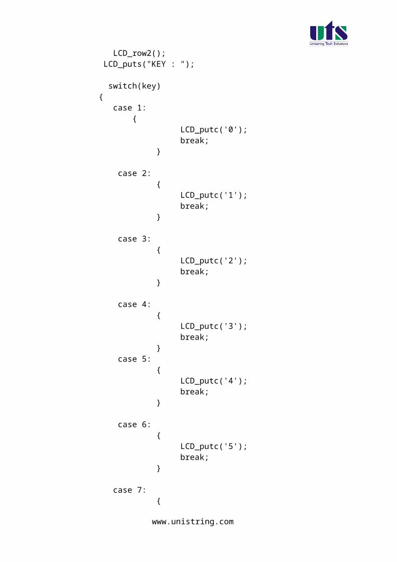
(8) Flash Magic Opens as shown in the figure
Change setting for Flash Magic as shown in the above figureCOM Port Choose the Appropriate COM Port of the computer. Generally it is COM1Baud Rate 9600Device 89V51RD2Interface None(ISP)Oscillator Freq (MHZ) 11.0592Tick Erase All Flash+Security+ClksTick Verify after Programming
Now Goto
Option-> Advanced Options → Hardware Configuration and uncheck the “Use DTR To Control Reset” as shown in the figure below
www.unistring.com
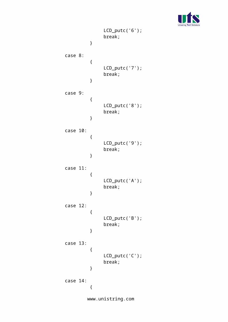
Browse for Hex file to be downloaded into the microcontroller
Select the switches.Hex file from the Folder in which switches.c file is located.
Turn On the Board Power. The RUN/PROG button can be any where (as 89V51RD2)
Connect the serial port to Board from Computer Press and hold the reset button on board and press start
button on flash magic. wait until a small window comes with message "Reset The Device Into ISP Mode "comes.Once this window comes release the reset button.
You can see the messages in flash magic tool as Erasing the Device, Programming the Device ,Verifying and Finished
(10)Once you get finished message in the flash magic. press reset once to enter in run mode.
C SOURCE CODE
// this program worked based on R-@R laders DAC module
www.unistring.com

#include <reg51.h> /* define 8051 registers */
void main () { /* main program */ unsigned char data1; unsigned char x;
unsigned char sine[64]={127, 139, 152, 164, 176, 187, 198, 208, 217, 225, 233, 239, 244, 249, 252, 253,
254, 253, 252, 249, 244, 239, 233, 225, 217, 208, 198, 187, 176, 164, 152, 139,
127, 115, 102, 90, 78, 67, 56, 46, 37, 29, 21, 15, 10, 5, 2, 1,
0, 1, 2, 5, 10, 15, 21, 29, 37, 46, 56, 67, 78, 90, 102, 115}; // sinewave look up chart data1 =0x00;
while(1) { for(x=0;x<64;x++)
{ P0 = sine[x];
} } }
Results/Discussion:
www.unistring.com
After programming the code into the microcontroller just reset the microcontroller and put it in the run mode. You can observe the sin wave in the CRO.
HARWARE CONFIGURATION
To test the board
Connect the DAC module to the P0 connector as shown below.The out put sine wave form You can observe the red wire is connected CRO positive and ground pin is connected ground on the Board
www.unistring.com
Experiment –6a
Write a program for interfacing the 16x2 LCD MODULE
Aim: Write a program for interfacing the 16x2 LCD module in 4- Bit mode.
Introduction:
In this experiment a program is written in C language to display a
message in the lcd first and second line and then clearing the first
and second line. This program is kept in an continuous loop and the
output can be seen on the board.
The program flow chart Write a program for lcd interface Compile the program and generate Hex file. The generated hex file will be downloaded in to the MC
and verify the result.
KIEL software is used for compilation of C files and the hex file can be generated. Experimental procedure:
Step1:
Open the kiel ide and you can see a menu as shoen in the figure.
www.unistring.com

Step 2:
To create a new project just click the project menu and click new microvision project , as shown in below figure.
www.unistring.com
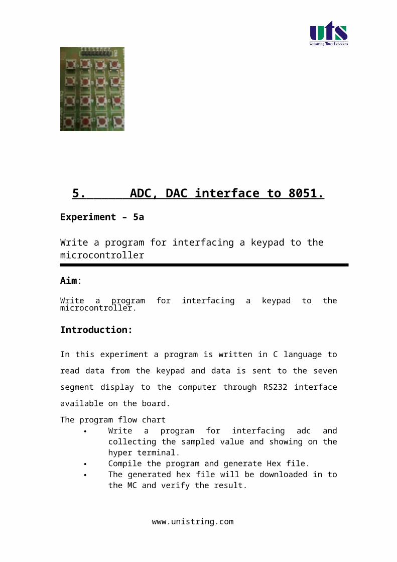
Step 3:
Then a dialog box will be opened to give the destination as shown in the figure. You can give the destination folder and save it.
www.unistring.com
Step 4:
To write a c file click the file menu and select the new document. The desired code is written in the document. And this document is needed to be added to the project.
Step 5:
In the project window on the left hand side you can see a project window .in the window a folder called target can be seen to that folder another folder can be seen as target source group1. the c file which is written nedded to be added to that folder . to add a c file to that folder right click the source group1 folder and a menu will be appeared as shown in the figure.
www.unistring.com

From that menu you can see add files to source group option. If you click that option the c file will be added to the project.
Step 6:
Before bulding the project some settings are to made, from the main menu click the flash, you can see the option as configure flash tools . you click that option you can find a menu as shown in the figure.
www.unistring.com

From that menu click output and select an option called create hex file. And in the target menu give the oscillator frequency as 11.0592.
Step 7:
Now all the hard work we have done to build the project and to create the hex file From the main menu select the project and in that an option called build target can be seen , just click that . if all the coding is correct and the syntaxes are correct an hex file will be generated.
Down loading the hex file to the target:
Open the Flash Magic tool for downloading into the Microcontroller Board. Click on Device menu select option you will be popped up with a window named choose device. Under choose device options select 8051 and click on Ok button to open flash magic tool to download the hex file in to the MC and is as shown below.
www.unistring.com

(9) Flash Magic Opens as shown in the figure
Change setting for Flash Magic as shown in the above figureCOM Port Choose the Appropriate COM Port of the computer. Generally it is COM1Baud Rate 9600Device 89V51RD2Interface None(ISP)Oscillator Freq (MHZ) 11.0592Tick Erase All Flash+Security+ClksTick Verify after Programming
Now Goto
Option-> Advanced Options → Hardware Configuration and uncheck the “Use DTR To Control Reset” as shown in the figure below
www.unistring.com
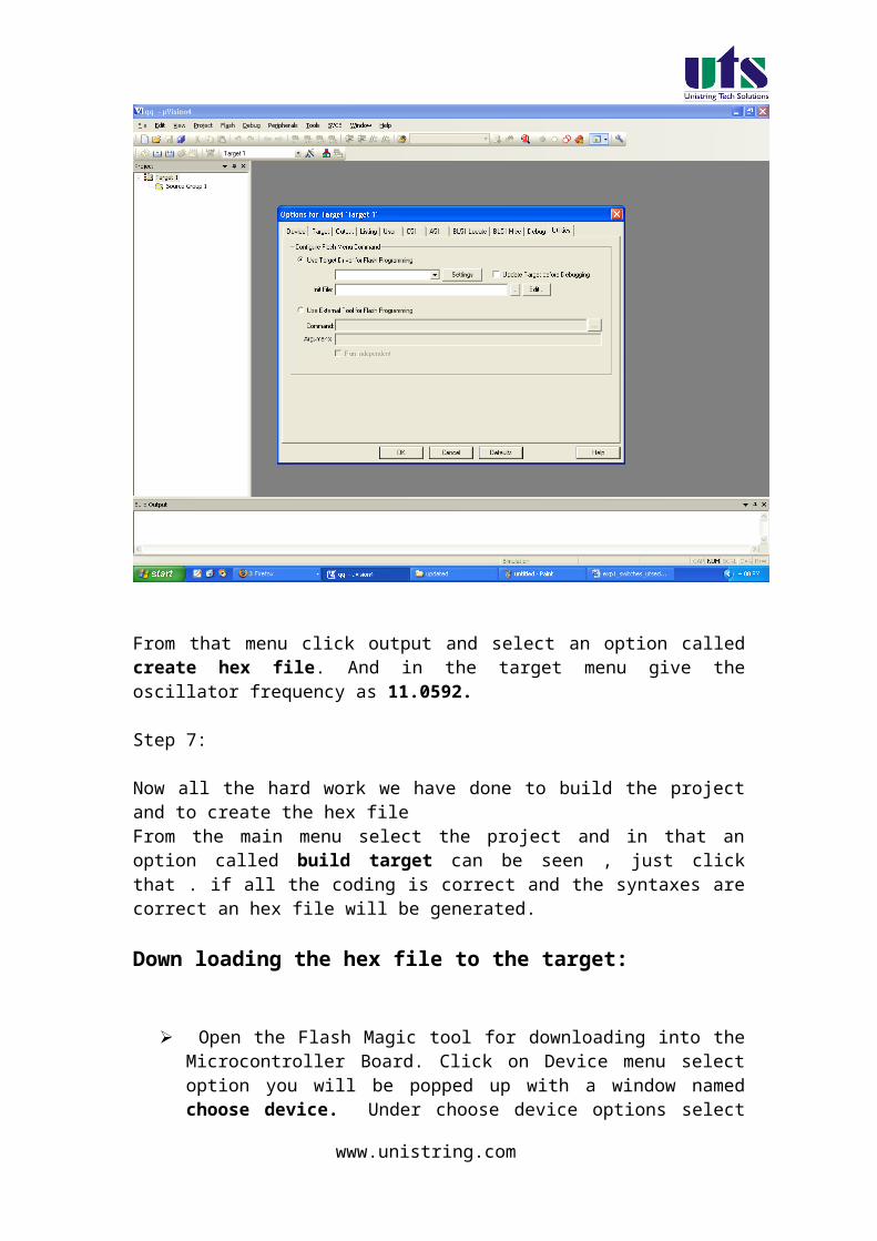
Browse for Hex file to be downloaded into the microcontroller
Select the switches.Hex file from the Folder in which switches.c file is located.
Turn On the Board Power. The RUN/PROG button can be any where (as 89V51RD2)
Connect the serial port to Board from Computer Press and hold the reset button on board and press start
button on flash magic. wait until a small window comes with message "Reset The Device Into ISP Mode "comes.Once this window comes release the reset button.
You can see the messages in flash magic tool as Erasing the Device, Programming the Device ,Verifying and Finished
(10)Once you get finished message in the flash magic. press reset once to enter in run mode.
Results/Output verification: Now the lcd program is running on Microcontroller. And the output can be seen in the board.
C SOURCE CODE
#include <reg51.h>
www.unistring.com

#include"lcd.h" // refer LCD.H code for more to about LCD
/* Hardware : Controller -> P89V51RD2 * XTAL -> 11.0592 MHz * * I/O : RS -> P2.5 * Enable -> P2.4 * Data4567 -> P2.0,P2.1,P2.2,P2.3 * Compiler : uvision 4 * Author : [email protected] * Date : 18/05/10 */
void Delay_sec(unsigned char s);
main( ){ LCD_init();
while(1){LCD_clear();Delay_sec(1);LCD_row1(); LCD_puts(" HELLO LCD123. ");
LCD_row2(); LCD_puts(" TEST PROGRAME ");Delay_sec(5);LCD_clear();Delay_sec(1);
LCD_row1(); LCD_puts(" Hello Welcome ");
LCD_row2(); LCD_puts("UNISTRING TECH P L");Delay_sec(5);}
}
void Delay_sec(unsigned char s){
unsigned char n;
for (n=0; n<s; n++){LCD_delay(250);LCD_delay(250);
}}
www.unistring.com

// Filename : lcd.h
#define LCD_DELAY 200 /* Delay for 1 ms */ #define LCD_clear() LCD_command(0x1) /* Clear display LCD */ #define LCD_origin() LCD_command(0x2) /* Set to origin LCD */ #define LCD_row1() LCD_command(0x80) /* Begin at Line 1 */ #define LCD_row2() LCD_command(0xC0) /* Begin at Line 2 */ #define lcd_port P2
//LCD Registers addresses#define LCD_EN 0x10#define LCD_RS 0x20
/*************************************************** * Prototype(s) * ***************************************************/sbit LCD_en=P2^4;sbit LCD_rs=P2^5;void LCD_delay(unsigned char ms);void LCD_enable();void LCD_command(unsigned char command);void LCD_putc(unsigned char ascii);void LCD_puts(unsigned char *lcd_string);void LCD_init();void lcd_reset();
/*************************************************** * Sources * ***************************************************/void LCD_delay(unsigned char ms){
unsigned char n;unsigned int i;for (n=0; n<ms; n++){
for (i=0; i<LCD_DELAY; i++); /* For 1 ms */}
}
void LCD_enable()
www.unistring.com

{ LCD_en = 1; /* Clear bit P2.4 */ LCD_delay(1); LCD_en = 0; /* Set bit P2.4 */}
void LCD_command(unsigned char command){ LCD_rs = 0; /* Clear bit P2.5 */ P2 = (P2 & 0xF0)|((command>>4) & 0x0F); LCD_enable();
LCD_delay(1); P2 = (P2 & 0xF0)|(command & 0x0F); LCD_enable(); LCD_delay(1);}
void LCD_putc(unsigned char ascii){ LCD_rs = 1; /* Set bit P2.5 */ P2 = (P2 & 0xF0)|((ascii>>4) & 0x0F); LCD_enable(); LCD_delay(1); P2 = (P2 & 0xF0)|(ascii & 0x0F); LCD_enable(); LCD_delay(1);}
void LCD_puts(unsigned char *lcd_string){
while (*lcd_string) {
LCD_putc(*lcd_string++);}
}
void lcd_reset(){ lcd_port = 0xFF; LCD_delay(20); lcd_port = 0x03+LCD_EN; lcd_port = 0x03; LCD_delay(10); lcd_port = 0x03+LCD_EN; lcd_port = 0x03; LCD_delay(1); lcd_port = 0x03+LCD_EN; lcd_port = 0x03; LCD_delay(1);
www.unistring.com

lcd_port = 0x02+LCD_EN; lcd_port = 0x02; LCD_delay(1);}
void LCD_init()
{ LCD_delay(10); lcd_reset();
LCD_en = 0; /* Set bit P2.4 */ LCD_rs = 0; /* Clear bit P2.5 */ LCD_command(0x28);
LCD_delay(1);LCD_clear(); LCD_delay(1); LCD_command(0x06);LCD_delay(1);
LCD_command(0x0C);LCD_delay(1);
LCD_clear(); /* Clear */ LCD_delay(100);}
Results/Discussion:
After programming the code into the microcontroller just reset the microcontroller. You can see some text displayed in the LCD display.
HARWARE CONFIGURATION
For LCD is connected port P2
RS -> P2.5
Enable -> P2.4
Data4567 -> P2.0, P2.1,P2.2, P2.3
Note:
For more information about refer 8051 book in the CD
www.unistring.com