8021x feature config_guide
TRANSCRIPT
Technical Guide
FEATURE OVERVIEW AND CONFIGURATION GUIDE
802.1x
Introduction802.1x is an IEEE standard providing a mechanism for authenticating devices attached to aLAN port or wireless device. Devices wishing to access services behind a port mustauthenticate themselves before any Ethernet packets are allowed to pass through. Theprotocol is referred to as 802.1x because it was initially defined in the IEEE standard 802.1x,published in 2001 and revised in 2004 and again as the current 802.1x 2010 standard.
Networks have two important requirements:
Security: Authentication and Authorization
Flexibility: The ability for users to roam
Networks need a device authentication method that is highly secure, but not tied to a port’sphysical location. Network resources presented to a given user need to be determined fromtheir authentication credentials.
802.1x user authentication satisfies these requirements. It is relatively uncomplicated and haslittle impact on network performance. It is a protocol that is medium-independent —beingequally as effective on wireless connections (802.11i) and wired connections. 802.1x userauthentication is rapidly becoming an expected component on networks.
alliedtelesis.com xC613-22005-00 REV A
Introduction
Products and software version that apply to this guide
This Guide applies to all AlliedWare Plus products, running version 5.4.4 or later.
Feature support may change in later software versions. For the latest information, see thefollowing documents:
The product’s Datasheet
The AlliedWare Plus Datasheet
The product’s Command Reference
These documents are available from the above links on our website at alliedtelesis.com.
Content
Introduction.............................................................................................................................................................................1
Products and software version that apply to this guide .......................................................................2
802.1x System Components.........................................................................................................................................3
802.1x component protocols..............................................................................................................................3
Example message sequence .................................................................................................................................5
Basic Steps in 802.1x Configuration..........................................................................................................................6
Multi-supplicant modes............................................................................................................................................6
Single supplicant...........................................................................................................................................................7
Multi-host.........................................................................................................................................................................7
802.1x VLAN Assignment ...............................................................................................................................................8
Dynamic VLAN assignment...................................................................................................................................8
802.1x Configuration Example.....................................................................................................................................9
Dynamic VLAN assignment with multiple supplicants ........................................................................ 11
Using a guest VLAN................................................................................................................................................ 13
Verify the operation of 802.1x.................................................................................................................................. 14
Names of commands used ................................................................................................................................ 15
Page 2 | 802.1x

802.1x System Components
802.1x System ComponentsThere are three main components to a system using 802.1x port authentication control:
Authenticator : the device that wishes to enforce authentication before allowing access toservices that are accessible behind it. An example of this is a switch that has 802.1x portauthentication control enabled.
Supplicant: the client that wishes to access services offered by the authenticator’s system.An example of this is a Windows XP Professional PC with an 802.1x client.
Authentication server : the device that uses the authentication credentials supplied by thesupplicant, to determine if the authenticator should grant access to its services. TheAlliedWare Plus implementation of 802.1x supports the use of a RADIUS. authenticationserver using Extensible Authentication Protocol (EAP) in conjunction with RADIUS.
Figure 1: 802.1x system components
802.1x component protocols
There are two protocols involved in the authentication conversation:
1. EAPoL exchanged between the supplicant and authenticator.
EAPoL—Extensible Authentication Protocol over LAN— is the protocol defined inIEEE802.1x.
2. RADIUS exchanged between the authenticator and authentication server.
RADIUS has received specific extensions to interoperate with EAPoL.
Switch
RADIUSServer
Supplicants
Authenticator
Authentication Server
802.1x | Page 3

802.1x System Components
The diagram below illustrates where EAPoL and RADIUS protocols are used in theauthentication conversation:
Figure 2: 801.X component protocols
Table 1: Basic steps in an 802.1x conversation
STEP ACTION
1 The supplicant informs the authenticator that it wants to initiate the conversation.
2 The authenticator requests the supplicant's credentials.
3 The supplicant sends username/password or X.509 certificate.
4 The authenticator wraps the supplicant's reply into a RADIUS packet and sends it to theRADIUS server.
5 The RADIUS server chooses an authentication method, and sends an appropriate requestto the supplicant as a ‘challenge’.
6 The RADIUS server and supplicant exchange some messages, ferried by the authenticator.
7 The RADIUS server eventually decides if the supplicant is allowed access and the RADIUSserver sends an Access-Accept or Access-Reject message to the Authenticator.
8 The authenticator sends an EAPoL-Success or EAPoL-Fail to the supplicant.
9 The supplicant has a session using the network (if accepted).
10 When the session is over, the supplicant sends a log-off message.
Switch
RADIUSServer
Supplicants
Authenticator
Authentication Server
RADIUS
EAPoL
Page 4 | 802.1x

802.1x System Components
Example message sequence
The diagram below illustrates an exchange using the EAP-MD5 authentication method,which is the simplest authentication method supported by 802.1x.
The EAPoL log-off message, of course, is not sent immediately after the other messages inthe diagram, but is sent later on, at the end of the supplicant’s data session, when it wishes todisconnect from the network.The EAPoL log-off message, of course, is not sent immediatelyafter the other messages in the diagram, but is sent later on, at the end of the supplicant’sdata session, when it wishes to disconnect from the network.
Figure 3: EAPoL message sequence
EAP-Request6 Radius-Access-Challenge
EAPOL-Start
EAP-Response/Identity (MyID)
EAP-Request/Identity
EAP-Request-Challenge (MD5)
EAP-Response-Challenge (MD5)
EAP-Success
EAP-Fail
EAPOL-Logoff
Radius-Access-Request
Radius-Access-Challenge
Radius-Access-Accept
Radius-Access-Reject
Authenticationfail
Authentication success
Authentication terminated
Port unauthorized
Port authorized
Port unauthorized
Authentication Server(RADIUS server)AuthenticatorSupplicant
EAPOL conversation
between supplicant
and switch.
RADIUS conversation
between switch and
RADIUS server.
1
5
4
7
2
10
3
8
6
8
7
Radius-Access-Request
Data Session9
802.1x | Page 5

Basic Steps in 802.1x Configuration
Basic Steps in 802.1x ConfigurationTo configure the switch operating as authenticator, follow the instructions below:
Figure 4: Configuring 802.1x basic steps
Step 1: Configure a RADIUS server for the switch to send requests to
awplus(config)# radius-server host 192.168.1.250 key <secret-key>
Step 2: Instruct 802.1x to use the configured RADIUS server
awplus(config)# aaa authentication dot1x default group radius
Step 3: Configure port1.0.5 for 802.1x authentication
awplus(config)# interface port1.0.5awplus(config-if)# dot1x port-control autoawplus(config-if)# spanning-tree portfast
Multi-supplicant modes
AlliedWare Plus can be configured to accept one or more supplicants downstream of a port.Three authentication host-modes are available:
single-supplicant: the default state, only one supplicant allowed per port.
multi-host: once the first host on a port is authenticated, all other downstream hosts areallowed without being authenticated (piggy-back mode).
multi-supplicant: multiple separate supplicants are individually authenticated on one port.
The command (entered in interface configuration mode for a physical port interface) is :
awplus(config-if)# auth host-mode {single-supplicant|multihost| multi-supplicant}
Switch
RADIUSServer
Supplicant
Authenticator
Authentication Server
192.168.1.250
192.168.1.45
port1.0.5
Page 6 | 802.1x

Basic Steps in 802.1x Configuration
This command controls how the switch deals with the situation where multipleauthentication supplicants are downstream of a single port. This is possible if an EAP passesthrough a Layer 2 switch which has been connected to the port, and the supplicants areattached to that Layer 2 switch.
Single supplicant
The first option that the command can set is single-host. With this option, only onesupplicant may be authenticated on the port. Once that host has been authenticated, noother supplicants may be authenticated until the first supplicant’s session has closed. Thismeans, of course, that none of the other hosts downstream of the port will be able to sendor receive traffic on that port.
This option is recommended when you know that there should only be one host connectedto a port. By limiting the port to a single authenticated host, you guard against theconsequences of someone accidentally or maliciously connecting a downstream switch to theport.
Multi-host
The next available host-mode option is multiple host mode (chosen by the parameter valuemulti-host). With this mode, once the first host has been authenticated on the port, all otherdownstream hosts are allowed without being authenticated. This is sometimes known aspiggy-back mode. It is useful when the downstream switch attached to the authenticatingport is an intelligent switch that can act as an authentication supplicant.
If you trust that malicious users cannot be connected to that switch but you do not know theidentity of those users, then you can simply authenticate the switch and then allow itsattached users to have network access. If the valid switch is disconnected and an invalid oneis connected which is not configured with the correct authentication credentials, then thedevices connected to the invalid switch will be blocked from accessing the network.
Figure 5: Configuring 802.1x multi-host
x900 Switch
RADIUSServer
Hosts
Authenticator
Authentication Server
Once the supplicant switch/router is authenticated
all traffic from these hosts is allowed
Switch or router that
can act as 802.1x supplicant
802.1x | Page 7

802.1x VLAN Assignment
802.1x VLAN Assignment
Dynamic VLAN assignment
Whilst the authentication of devices attaching to the network is primarily driven by securityconsiderations, it has significant spin-off benefits.
Once a device has been authenticated, the network knows the identity of the device and/orits user. Decisions can be made, based on this identity. In particular, it is possible to decidewhat network environment, and level of access, to present to this device and its user.
The standard mechanism via which a user’s network environment is controlled isVLANmembership. Once a user’s packets are classified into a particularVLAN, the user’s access tothe network will be controlled by the constraints that have been put on thatVLANthroughout the network.
For this reason, it is now common for LAN switches to have the ability to dynamically assigntheVLAN into which a device’s traffic will be classified, once that device has beenauthenticated.
DynamicVLAN assignment is achieved by a collaboration between the authenticator (theLAN switch) and the authentication server (the RADIUS server). When the RADIUS serversends back a RADIUS accept message to the authenticator, it can also include otherattributes in that message that identify aVLAN to which the authenticated device should beassigned.
DynamicVLAN assignment is a powerful extension to 802.1x, as it enables:
Identity-based networking—the user gets the same environment no matter where theyconnect.
Guest Access—guest users are allowed access to very limited parts of the network.
NAC—level of access is based on a workstation’s security status.
Figure 6: Dynamic VLAN assignment
x900 Switch
RADIUSServer
Supplicants
Authenticator
Authentication Server
RADIUS access-accept
message says “supplicant is
accepted, put them into VLAN X”
Page 8 | 802.1x
802.1x Configuration Example
Authenticator configuration
In addition to the basic 802.1x configuration, some further configuration is required toenable DynamicVLAN creation on the switch. TheVLANs that can be dynamically assignedmust be present in theVLAN database:
awplus(config)# vlan database awplus(config-vlan)# vlan xawplus(config-vlan)# vlan yawplus(config-vlan)# vlan zawplus(config-vlan)# exit
Ports that acceptVLAN membership dynamically have to be enabled for dynamicVLANcreation:
awplus(config)# interface port1.0.5awplus(config-if)# auth dynamic-vlan-creation
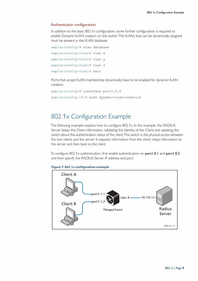
802.1x Configuration Example The following example explains how to configure 802.1x. In this example, the RADIUSServer keeps the Client information, validating the identity of the Client and updating theswitch about the authentication status of the client.The switch is the physical access betweenthe two clients and the server. It requests information from the client, relays information tothe server and then back to the client.
To configure 802.1x authentication, first enable authentication on port1.0.1 and port1.0.2
and then specify the RADIUS Server IP address and port.
Figure 7: 802.1x configuration example
802-1x_1.1
Client B
Client A
192.126.12.1port1.1.1
RadiusServer
port1.1.2vlan 4
802.1x | Page 9

802.1x Configuration Example
Table 2: 802.1x configuration on the switch
awplus#configure terminal Enter the Global Configuration mode.
awplus(config)#aaa authentication dot1x
default group radiusEnable authentication globally.
awplus(config)#interface port1.0.1 Specify the interface (port1.0.1) to be configured and enter the
Interface mode.
awplus(config-if)#dot1x port-control auto Enable authentication (via RADIUS) on port1.0.1.
awplus(config-if)#dot1x control-direction
bothBlock traffic in both directions, other than authentication packets,until authentication is complete.
awplus(config-if)#exit Exit the Interface Configuration mode and enter the
Global Configuration mode.
awplus(config)#interface port1.0.2 Specify the interface (port1.0.2) you are configuring and enter the
Interface mode.
awplus(config-if)#dot1x port-control auto Enable authentication (via RADIUS) on port1.0.2.
awplus(config-if)#exit Exit the Interface Configuration mode and enter the
Global Configuration mode.
awplus(config)#radius-server host
192.126.12.1 auth-port 1812Specify the RADIUS Server address (192.126.12.1) andauthentication port.
awplus(config)#radius-server key secret Specify the shared key secret between the RADIUS server and the
client.
awplus(config)#interface vlan4 Specify the vlan (vlan4) to be configured and enter the Interface
mode.
awplus(config-if)#ip address 192.126.12.2/24 Set the IP address on vlan4.
Page 10 | 802.1x
802.1x Configuration Example
Dynamic VLAN assignment with multiple supplicants
In multi-supplicant mode, what happens if two supplicants downstream of the same port areassigned to differentVLANs?The auth dynamic-vlan-creation command has twoparameters that govern the operation in this situation: rule and type.
The rule parameter
The first parameter is the rule parameter.
For SBx8100, SBx908 and x900 Series switches (the situation is different for the x210, x230,x310, x510, x600, x610 and x930 Series, as we will see below) it is not possible to assigndifferentVLANs to untagged traffic from different supplicants. On the SBx8100, SBx908 andx900, dynamicVLAN assignment effectively says ‘the one untaggedVLAN to be used on theauthenticating port is VLAN x’. So, if the first supplicant is authenticated and assignedVLAN45, then the authenticating port will classify all untagged traffic arriving on the port intoVLAN 45. But if a second supplicant downstream of the same port then authenticates, andthe RADIUS server assignsVLAN 56 to that supplicant, the switch then faces a dilemma. It isalready usingVLAN 45 as the untaggedVLAN on that port; it cannot useVLAN 56 as well.
There are two ways that the switch can resolve this situation. It can:
1. Allow the second supplicant to access the network, but assign its data toVLAN 45.
2. Block the second supplicant from having network access.
The rule parameter configures which of these choices the switch will opt for. If rule is set topermit, then option (1) above is chosen. If rule is set to deny, then option (2) above ischosen.
The type parameter
The second parameter is the type parameter.
The type parameter applies only to the x210, x230, x310, x510, x600, x610 and x930 Seriesswitches. This is because these switches support MAC-basedVLANs, whereas the x8100,x900 Series and SBx908 do not.
The effect of the type parameter is to make use of the x210, x230, x310, x510, x600, x610and x930 MAC-basedVLAN support to provide a better solution to the case wheredifferent supplicants downstream of a single port are dynamically allocated to differentVLANs.
If type is set to the value single, then the MAC-basedVLAN capability is not used, and theport’s behavior in the different-dynamic-VLANs situation will be controlled by the ruleparameter.
However, if type is set to multi, the switch brings the MAC-basedVLAN capability into play.This capability enables it to support multiple different untaggedVLANs on the same port.This is achieved by associatingVLAN membership with the source MAC address of theincoming packets.
So, when different supplicants downstream of a single port are dynamically assigned differentVLANs, the switch simply builds a table that maps supplicants’ MAC addresses to theirdynamically assignedVLANs.
802.1x | Page 11

802.1x Configuration Example
The combination of these parameters results in three options for handling the case wheredifferentVLANs are assigned to supplicants on the same ports.
Option 1 Deny access to supplicant assigned a different VLAN.
If the first supplicant authenticated on the port is assignedVLAN X, then any supplicantssubsequently assigned a differentVLAN are denied access. This is the default state whendynamicVLAN creation is enabled.
This is configured with:
awplus(config-if)# auth dynamic-vlan-creation rule deny
Figure 8: Deny access to supplicant assigned to a different VLAN
Option 2 Force all supplicants into the same VLAN
If the first supplicant authenticated on the port is assignedVLAN X, then any supplicantssubsequently assigned a differentVLAN are allowed access, but forced intoVLAN X
This is configured with:
awplus(config-if)# auth dynamic-vlan-creation rule permit
Figure 9: Force all supplicants into the same VLAN
2. Supplicant accepted and assigned to VLAN11. Authenticator allows access.
1. Supplicant accepted and assigned VLAN 10
x900 Switch
2. Supplicant accepted by RADIUS server
and assigned VLAN 11. Authenticator
allows access, but puts supplicant into
VLAN 10.
Authenticator
1. Supplicant accepted and
assigned VLAN 10
Page 12 | 802.1x

802.1x Configuration Example
Option 3 Dynamically assign multiple VLANs to one port
On the x210, x230, x310, x510, x600, x610 and x930 switches, it is actually possible toassign differentVLANs to different supplicants downstream of the same port.
This is configured with:
awplus(config-if)# auth dynamic-vlan-creation rule permit type multi
Figure 10: Dynamically assign multiple VLANs to one port
The switch can assignVLAN membership to packets based on source MAC:
Packets from MAC of supplicant 1 are assigned toVLAN10
Packets from MAC of supplicant 2 are assigned toVLAN11
This feature is not supported on SBx8100, x900 and SwitchBlade x908 switches.
Using a guest VLAN
Whilst you need to authenticate the users who will have access to the important serviceswithin your network, you might also want to provide some basic level of access to users whofail to authenticate.
For example, visitors to an enterprise will often need to have Internet access. It would bedesirable to have a secure, convenient way to provide this Internet access via the corporateLAN.
By default, 802.1x denies access to users who fail authentication.
Guests are not known to the RADIUS server, so fail authentication. The solution is toprovide a GuestVLAN which is configured with:
awplus(config)# interface port1.0.5awplus(config-if)# auth guest-vlan <vlan id>
x600 Switch
2. Supplicant accepted and assigned to VLAN 11. Authenticator allows access and allocates this supplicant’s data to VLAN 11.
Authenticator
1. Supplicant accepted andassigned VLAN 10
802.1x | Page 13

Verify the operation of 802.1x
Figure 11: Using a guest VLAN
If a supplicant attempts authentication and fails or does not even attempt authentication (no802.1x client in the PC) then they are dynamically assigned to the guestVLAN.
Verify the operation of 802.1x
When a supplicant has been authenticated on a port the details of the authentication can beseen with:
show dot1x supplicant int port1.0.5Interface port1.0.5
authenticationMethod: dot1xtotalSupplicantNum: 1
authorizedSupplicantNum: 1macBasedAuthenticationSupplicantNum: 0dot1xAuthenticationSupplicantNum: 1WebBasedAuthenticationSupplicantNum:otherAuthenticationSupplicantNum: 0
Supplicant name: Engineer01
Supplicant address:0002.b363.319f authenticationMethod: 802.1x
portStatus: Authorized - currentId: 9abort:F fail:F start:F timeout:F success:TPAE: state: Authenticated - portMode: AutoPAE: reAuthCount: 0 - rxRespId: 0PAE: quietPeriod: 60 - maxReauthReq: 2BE: state: Idle - reqCount: 0 - idFromServer: 8CD: adminControlledDirections: both - operControlledDirections:
bothCD: bridgeDetected: falseKR: rxKey: falseKT: keyAvailable: false - keyTxEnabled: falsedynamicVlanId: 20assignment enabled
10/100 Link
1 Gigabit Link
Link aggregation
x900 stack
x600
Supplicant
assigned to guest
vlan
Windows 2008 server
AR770
8000GSInternet
Private Zone
Enterprise CAserver
Client devices
Public/Private
Zone
ACLs used to ensure GUEST VLAN
traffic goes to the Internet and nowhere else
<--- Authenticated by 802.1x
<--- Supplicant name<---MAC of authenticated device
<---VLAN assigned, if dynamicVLA
Page 14 | 802.1x

When a supplicant has been authenticated, and assigned to aVLAN, the port theyauthenticated on will then be seen to be a member of thatVLAN.
Names of commands used
dot1x port-control radius-server host radius-server key
Validation commands
show dot1x show dot1x interface
show vlan 20
VLAN ID Name Type State Member ports(u)-Untagged, (t)-Tagged======= ================ ======= ======= ======================20 Engineering STATIC ACTIVE port1.0.5(u)
show vlan 30
VLAN ID Name Type State Member ports(u)-Untagged, (t)-Tagged======= ================ ======= ======= ======================30 Marketing STATIC ACTIVE port1.0.5(u)
C613-22005-00 REV A
North America Headquarters | 19800 North Creek Parkway | Suite 100 | Bothell | WA 98011 | USA | T: +1 800 424 4284 | F: +1 425 481 3895Asia-Pacifi c Headquarters | 11 Tai Seng Link | Singapore | 534182 | T: +65 6383 3832 | F: +65 6383 3830EMEA & CSA Operations | Incheonweg 7 | 1437 EK Rozenburg | The Netherlands | T: +31 20 7950020 | F: +31 20 7950021
alliedtelesis.com© 2015 Allied Telesis Inc. All rights reserved. Information in this document is subject to change without notice. All company names, logos, and product designs that are trademarks or registered trademarks are the property of their respective owners.