802.15.4g-2012
DESCRIPTION
Low-Rate Wireless Personal AreaNetworks (LR-WPANs)TRANSCRIPT
�
���
�
Sponsored by the LAN/MAN Standards Committee
IEEE 3 Park Avenue New York, NY 10016-5997 USA 27 April 2012
IEEE Computer Society
IEEE Std 802.15.4g™-22012(Amendment to
IEEE Std 802.15.4™-2011)
IEEE Standard for Local and metropolitan area networks—
Part 15.4: Low-Rate Wireless Personal Area Networks (LR-WPANs)
Amendment 3: Physical Layer (PHY) Specifications for Low-Data-Rate, Wireless, Smart Metering Utility Networks


IEEE Std 802.15.4g™-2012(Amendment to
IEEE Std 802.15.4™-2011)
IEEE Standard forLocal and metropolitan area networks—
Part 15.4: Low-Rate Wireless Personal Area Networks (LR-WPANs)
Amendment 3: Physical Layer (PHY) Specifications for Low-Data-Rate, Wireless, Smart Metering Utility Networks
Sponsor
LAN/MAN Standards Committeeof theIEEE Computer Society
Approved 29 March 2012
IEEE-SA Standards Board

The Institute of Electrical and Electronics Engineers, Inc.3 Park Avenue, New York, NY 10016-5997, USA
Copyright © 2012 by The Institute of Electrical and Electronics Engineers, Inc.All rights reserved. Published 27 April 2012. Printed in the United States of America.
IEEE is a registered trademark in the U.S. Patent & Trademark Office, owned by The Institute of Electrical and ElectronicsEngineers, Incorporated.
Print: ISBN 978-0-7381-7259-0 STD97234PDF: ISBN 978-0-7381-7365-8 STDPD97234
IEEE prohibits discrimination, harassment, and bullying. For more information, visit http://www.ieee.org/web/aboutus/wha-tis/policies/p9-26.html.No part of this publication may be reproduced in any form, in an electronic retrieval system or otherwise, without the priorwritten permission of the publisher.
Abstract: In this amendment to IEEE Std 802.15.4-2011, outdoor low-data-rate, wireless, smartmetering utility network requirements are addressed. Alternate PHYs aredefined as well as onlythose MAC modifications needed to support their implementation.
Keywords: ad hoc network, IEEE 802.15.4, IEEE 802.15.4g, low data rate, low power, LR-WPAN,mobility, PAN, personal area network, radio frequency, RF, short range, smart metering utilitynetworks, SUN, wireless, wireless personal area network, WPAN
Notice and Disclaimer of Liability Concerning the Use of IEEE Documents: IEEE Standards documents are developedwithin the IEEE Societies and the Standards Coordinating Committees of the IEEE Standards Association (IEEE-SA) StandardsBoard. IEEE develops its standards through a consensus development process, approved by the American National StandardsInstitute, which brings together volunteers representing varied viewpoints and interests to achieve the final product. Volunteersare not necessarily members of the Institute and serve without compensation. While IEEE administers the process and establishesrules to promote fairness in the consensus development process, IEEE does not independently evaluate, test, or verify theaccuracy of any of the information or the soundness of any judgments contained in its standards.
Use of an IEEE Standard is wholly voluntary. IEEE disclaims liability for any personal injury, property or other damage, of anynature whatsoever, whether special, indirect, consequential, or compensatory, directly or indirectly resulting from thepublication, use of, or reliance upon any IEEE Standard document.
IEEE does not warrant or represent the accuracy or content of the material contained in its standards, and expressly disclaimsany express or implied warranty, including any implied warranty of merchantability or fitness for a specific purpose, or that theuse of the material contained in its standards is free from patent infringement. IEEE Standards documents are supplied "AS IS."
The existence of an IEEE Standard does not imply that there are no other ways to produce, test, measure, purchase, market, orprovide other goods and services related to the scope of the IEEE standard. Furthermore, the viewpoint expressed at the time astandard is approved and issued is subject to change brought about through developments in the state of the art and commentsreceived from users of the standard. Every IEEE standard is subjected to review at least every ten years. When a document ismore than ten years old and has not undergone a revision process, it is reasonable to conclude that its contents, although still ofsome value, do not wholly reflect the present state of the art. Users are cautioned to check to determine that they have the latestedition of any IEEE standard.
In publishing and making its standards available, IEEE is not suggesting or rendering professional or other services for, or onbehalf of, any person or entity. Nor is IEEE undertaking to perform any duty owed by any other person or entity to another. Anyperson utilizing any IEEE Standards document, should rely upon his or her own independent judgment in the exercise ofreasonable care in any given circumstances or, as appropriate, seek the advice of a competent professional in determining theappropriateness of a given IEEE standard.
Translations: The IEEE consensus development process involves the review of documents in English only. In the event that anIEEE standard is translated, only the English version published by IEEE should be considered the approved IEEE standard.
Official Statements: A statement, written or oral, that is not processed in accordance with the IEEE-SA Standards BoardOperations Manual shall not be considered the official position of IEEE or any of its committees and shall not be considered tobe, nor be relied upon as, a formal position of IEEE. At lectures, symposia, seminars, or educational courses, an individualpresenting information on IEEE standards shall make it clear that his or her views should be considered the personal views ofthat individual rather than the formal position of IEEE.
Comments on Standards: Comments for revision of IEEE Standards documents are welcome from any interested party,regardless of membership affiliation with IEEE. However, IEEE does not provide consulting information or advice pertainingto IEEE Standards documents. Suggestions for changes in documents should be in the form of a proposed change of text,together with appropriate supporting comments. Since IEEE standards represent a consensus of concerned interests, it isimportant to ensure that any responses to comments and questions also receive the concurrence of a balance of interests. Forthis reason, IEEE and the members of its societies and Standards Coordinating Committees are not able to provide an instantresponse to comments or questions except in those cases where the matter has previously been addressed. Any person whowould like to participate in evaluating comments or revisions to an IEEE standard is welcome to join the relevant IEEE workinggroup at http://standards.ieee.org/develop/wg/.
Comments on standards should be submitted to the following address:
Secretary, IEEE-SA Standards Board445 Hoes LanePiscataway, NJ 08854-4141USA
Photocopies: Authorization to photocopy portions of any individual standard for internal or personal use is granted by The Institute of Electrical and Electronics Engineers, Inc., provided that the appropriate fee is paid to Copyright Clearance Center. To arrange for payment of licensing fee, please contact Copyright Clearance Center, Customer Service, 222 Rosewood Drive, Danvers, MA 01923 USA; +1 978 750 8400. Permission to photocopy portions of any individual standard for educational classroom use can also be obtained through the Copyright Clearance Center.

Notice to users
Laws and regulations
Users of IEEE Standards documents should consult all applicable laws and regulations. Compliance with theprovisions of any IEEE Standards document does not imply compliance to any applicable regulatoryrequirements. Implementers of the standard are responsible for observing or referring to the applicableregulatory requirements. IEEE does not, by the publication of its standards, intend to urge action that is notin compliance with applicable laws, and these documents may not be construed as doing so.
Copyrights
This document is copyrighted by the IEEE. It is made available for a wide variety of both public and privateuses. These include both use, by reference, in laws and regulations, and use in private self-regulation,standardization, and the promotion of engineering practices and methods. By making this documentavailable for use and adoption by public authorities and private users, the IEEE does not waive any rights incopyright to this document.
Updating of IEEE documents
Users of IEEE Standards documents should be aware that these documents may be superseded at any timeby the issuance of new editions or may be amended from time to time through the issuance of amendments,corrigenda, or errata. An official IEEE document at any point in time consists of the current edition of thedocument together with any amendments, corrigenda, or errata then in effect. In order to determine whethera given document is the current edition and whether it has been amended through the issuance ofamendments, corrigenda, or errata, visit the IEEE-SA Website or contact the IEEE at the address listedpreviously. For more information about the IEEE Standards Association or the IEEE standards developmentprocess, visit the IEEE-SA Website.
Errata
Errata, if any, for this and all other standards can be accessed at the following URL: http://standards.ieee.org/findstds/errata/index.html. Users are encouraged to check this URL for errataperiodically.
iv Copyright © 2012 IEEE. All rights reserved.

Patents
Attention is called to the possibility that implementation of this standard may require use of subject mattercovered by patent rights. By publication of this standard, no position is taken by the IEEE with respect to theexistence or validity of any patent rights in connection therewith. If a patent holder or patent applicant hasfiled a statement of assurance via an Accepted Letter of Assurance, then the statement is listed on the IEEE-SA Website at http://standards.ieee.org/about/sasb/patcom/patents.html. Letters of Assurance may indicatewhether the Submitter is willing or unwilling to grant licenses under patent rights without compensation orunder reasonable rates, with reasonable terms and conditions that are demonstrably free of any unfairdiscrimination to applicants desiring to obtain such licenses.
Essential Patent Claims may exist for which a Letter of Assurance has not been received. The IEEE is notresponsible for identifying Essential Patent Claims for which a license may be required, for conductinginquiries into the legal validity or scope of Patents Claims, or determining whether any licensing terms orconditions provided in connection with submission of a Letter of Assurance, if any, or in any licensingagreements are reasonable or non-discriminatory. Users of this standard are expressly advised thatdetermination of the validity of any patent rights, and the risk of infringement of such rights, is entirely theirown responsibility. Further information may be obtained from the IEEE Standards Association.
Copyright © 2012 IEEE. All rights reserved. v

Participants
At the time the draft of this standard was sent to sponsor ballot, the IEEE P802.15 Working Group had thefollowing voting members:
Robert F. Heile, ChairRick Alfvin, Vice Chair
Patrick W. Kinney, Vice Chair, SecretaryJames P. K. Gilb, Technical Editor
Clint Chaplin, Treasurer
Philip E. Beecher, Task Group 4g ChairHiroshi Harada, Task Group 4g Co-vice Chair
Clinton C. Powell, Task Group 4g Co-vice ChairMonique B. Brown, Task Group 4g Co-editorKuor-Hsin Chang, Task Group 4g Co-editorStephen P. Pope, Task Group 4g Secretary
Jana van Greunen, Task Group 4g Secretary (past)
Chin-Sean Sum, Coexistence Assurance Contributing EditorAlina Liru Lu, Task Group 4g Assistant Secretary
Benjamin A. Rolfe, Task Group 4g Assistant SecretaryKunal Shah, Task Group 4g Assistant Secretary
Emad AfifiGahng-Seop AhnRoberto AielloArthur Astrin Taehan Bae Michael Bahr John Barr Anuj BatraTuncer Baykas Ashutosh BhatiaGhulam BhattiGary BirkMathew BoytimPeter David BradleyNancy BravinDavid BritzSverre BrubkBrian BuchananJohn BuffingtonKiran Bynam Brent CainEdgar H. CallawayChris CalvertRuben CardozoDouglas CastorJaesang ChaRussell ChandlerSoo-Young ChangClint ChaplinHind ChebboChang-Soon ChoiSangsung ChoiCiaran ConnellDavid CypherMatthew DahlDavid Davenport
Mark DawkinsHendricus De Ruijter Upkar DhaliwalGang DingPaul Dixon Guido DolmansIgor DotlicMichael DowDietmar EggertDavid EvansCharles FarlowJohn Farserotu Jeffrey FischbeckMike FischerGeorge FlammerRyosuke FujiwaraNoriyasu FukatsuKiyoshi Fukui John GeigerGregory GilloolyTim GodfreyPaul Gorday Elad GottlibRobert HallShinsuke Hara Timothy HarringtonRodney HemmingerMarco HernandezGarth HillmanJin-Meng HoWei HongSrinath HosurDavid A. HowardJung-Hwan Hwang Taeho HwangIchirou Ida
Tetsushi Ikegami Akio Iso Yeong Min JangAdrian JenningsWuncheol JeongSteven JillingsNoh-Gyoung Kang Tae-Gyu Kang Shuzo KatoTatsuya KatoJeritt KentPrithpal KhakuriaDae Ho KimDong-Sun KimDukhyun KimJaehwan KimJeffrey KingRyuji Kohno Fumihide Kojima Bruce Kraemer Raymond KrasinskiMasahiro KurodaJohn Lampe Zhou Lan Khanh LeCheolhyo LeeHyungsoo LeeMyung LeeDaniel Lewis Huan-Bang Li Liang Li Sang-Kyu LimJeremy LinkMike LynchRobert MasonTomokuni Matsumura
vi
Copyri ght © 2012 IEEE. All rights reserved.
Major contributions were received from the following individuals:
Jeff McCulloughMichael McGillanMichael D. McInnis Michael McLaughlin Charles MilletSiamak MirnezamiRishi MohindraEmmanuel MonnerieRajendra Moorti Robert MoskowitzHamilton MoyPeter MurrayTheodore MyersChiu Ngo Paul Nikolich Hirohito NishiyamaDavid OlsonOkundu Omeni Ryoji OnoLaurent Ouvry James PaceHyung-Il Park Jahng ParkSeung-Hoon ParkTaejoon ParkRanjeet PatroAl PetrickDalibor PokrajacDaniel PopaRichard PowellChang-Woo PyoMohammad Rahman
Sridhar RajagopalJayaram RamasastryMarc ReedIvan ReedeRichard RobertsCraig RodineJune Chul RohSeung-Moon RyuDidier SaganKentaro SakamotoWill San FilippoH. SanderfordKamran Sayrafian Timothy SchmidlMichael Schmidt Jean Schwoerer Cristina SeibertNeal SeidlSteve ShearerStephen Shellhammer Shusaku Shimada Chang Sub Shin Cheol Ho ShinMichael Sim Jonathan SimonJaeseung SonPaul StadnikRené StruikHui-Hsia SungGu SungiKenichi Takizawa Hirokazu Tanaka
Larry TaylorMark ThompsonJames TomcikIchihiko Toyoda David TraceyKhanh TranJerry UptonHartman van WykMichel VeilletteBilly VersoBhupender VirkJoachim WalewskiJunyi WangQuan WangXiang WangAndy WardScott WeikelNicholas WestMark WilburLudwig WinkelEun Tae Won Alan Chi Wai WongTao XingWen-Bin Yang Yang YangKazuyuki YasukawaKamya Yazdandoost Kaoru Yokoo Mu Zhao Bin Zhen
Roberto AielloMatt BoytimSverre BrubakJohn BuffingtonEdgar H. CallawaySangsung Choi Hendricus De RuijterDietmar EggertGeorge FlammerJames P. K. GilbElad GottlibRodney C. HemmingerDavid A. HowardSteven JillingsSeong-Soon JooJeritt Kent
Jeffrey KingFumihide KojimaJohn LampeKhanh Tuan LeLiang LiRobert MasonCharles MilletEmmanuel MonnerieTae-Joon ParkGilles PicardFrank PoegelDaniel PopaJayaram RamasastryKentaro SakamotoRuben Salazar
Britton SanderfordTimothy M. SchmidlMichael SchmidtCristina SeibertSteve ShearerJie Shen Cheolho ShinLarry TaylorKhurram Waheed Xiang Wang Scott WeikelMark WilburHartman van WykKazuyuki YasukawaZhen Feng Zhao
Copyright © 2012 IEEE. All rights reserv
ed. vii
The following members of the balloting committee voted on this standard. Balloters may have voted forapproval, disapproval, or abstention.
Jon AdamsEmad AfifiRoberto AielloRick AlfvinNobumitsu AmachiPatrick AmihoodButch AntonTakamasa AsanoArthur AstrinStefan AustMichael BahrJonathan BaileyJay BainTakahiro BannoEdward BaranskiAnuj BatraPhilip E. BeecherHarry BimsMathew BoytimNancy BravinVern BrethourMonique B. BrownJohn BuffingtonWilliam ByrdBrent CainEdgar H. CallawayRadhakrishna CanchiDave CavalcantiKuor-Hsin ChangClint ChaplinGer-Chih ChouKeith ChowCharles CookMichael CoopJoseph DecuirPatrick DiamondThomas DineenSourav DuttaPeter EcclesineRichard EdgarStanislav FilinWill San FilippoGeorge FlammerKimberly FranciscoAvraham FreedmanKiyoshi FukuiKeisuke FukushimaJohn GeigerJames P. K. GilbGregory GilloolyTim GodfreyElad GottlibRandall GrovesMichael GundlachHenrik GustafssonJose GutierrezC. GuyRainer HachChristopher HansenHiroshi HaradaSatoshi Hasako
Marco HernandezRyoichi HigashiSrinath HosurDavid A. HowardHeqing HuangDavid HunterIchirou IdaTetsushi IkegamiNoriyuki IkeuchiAkio IsoAtsushi ItoRaj JainOyvind JanbuJunghoon JeeJorjeta JetchevaSteven JillingsTal KaitzShinkyo KakuAiichiro KashiwagiTakuya KawataRuediger KaysRaymond H. KelleyJeritt KentStuart J. KerryBrian KiernanIl Han KimYongbum KimJeffrey KingPatrick W. KinneyFumihide KojimaBruce KraemerYasushi KudohGeoff LadwigZhou LanKhanh Tuan LeJan-Ray LiaoArthur LightHaiTao LiuAlina Liru LuDaniel LubarWilliam LumpkinsGreg LuriMike LynchElvis MaculubaStephen MakgillRobert MasonJeff McCulloughMichael McGillanMichael D. McInnisMichael McLaughlinGary MichelCharles MilletPaul MobusApurva ModyEmmanuel MonnerieJose MoralesKenichi MoriPeter MurrayNabil NasserMichael S. NewmanPaul Nikolich
John NotorSatoshi ObaraMasayuki OodoChris OsterlohSatoshi OyamaFrank PoegelDalibor PokrajacDaniel PopaClinton C. PowellVenkatesha PrasadMohammad RahmanJayaram RamasastryMark RantaCharles RazzellMaximilian RiegelRobert RobinsonCraig RodineBenjamin A. RolfeCarl RoyerRandall SafierTatsuhiro SakaiKentaro SakamotoKazuyuki SakodaH. SanderfordShigenobu SasakiKatsuyoshi SatoNaotaka SatoBartien SayogoTimothy M. SchmidlMichael SchmidtCristina SeibertKunal ShahDurgaprasad ShamainDonald ShaverSteve ShearerJie ShenShusaku ShimadaJohn ShortGil ShultzJonathan SimonAmjad SoomroThomas StaraiRené StruikWalter StrupplerMark SturzaChin-Sean SumChen SunYanjun SunTakahisa TaiJun Ichi TakadaYoichi TanakaLarry TaylorHa Nguyen TranMark-Rene UchidaAnna UrraDavid UyJana van GreunenDmitri VarsanofievPrabodh VarshneyJohn VergisDalton Victor
viii
Cop yright © 2012 IEEE. All rights reserved.
When the IEEE-SA Standards Board approved this standard on 29 March 2012, it had the followingmembership:
Richard H. Hulett, ChairJohn Kulick, Vice ChairRobert Grow, Past ChairJudith Gorman, Secretary
*Member Emeritus
Also included are the following nonvoting IEEE-SA Standards Board liaisons:
Richard DeBlasio, DOE RepresentativeMichael Janezic, NIST Representative
Michelle TurnerIEEE Standards Program Manager, Document Development
Patricia A. GerdonIEEE Standards Program Manager, Technical Program Development
Bhupender VirkJerome VivianoGeorge VlantisKhurram WaheedJunyi WangStanley WangXiang Wang
Deric WatersHung-Yu WeiScott WeikelMark WilburLudwig WinkelAndreas WolfAriton Xhafa
Tao XingYang YangMasahiro YasuiKazuyuki YasukawaTan Pek YewJianming YuanOren Yuen
Satish AggarwalMasayuki AriyoshiPeter BalmaWilliam BartleyTed BurseClint ChaplinWael DiabJean-Philippe Faure
Alexander GelmanPaul HouzéJim HughesYoung Kyun KimJoseph L. Koepfinger*David J. LawThomas LeeHung Ling
Oleg LogvinovTed OlsenGary RobinsonJon Walter RosdahlMike SeaveyYatin TrivediPhil WinstonYu Yuan
Copyright © 2012 IEEE. All rights reserve
d. ix
Introduction
This amendment specifies alternate PHYs in addition to those of IEEE Std 802.15.4-2011. In addition to thenew PHYs, the amendment also defines those MAC modifications needed to support their implementation.
The alternate PHYs support principally outdoor, low-data-rate, wireless, smart metering utility network(SUN) applications under multiple regulatory domains. The SUN PHYs are as follows:
— Multi-rate and multi-regional frequency shift keying (MR-FSK) PHY
— Multi-rate and multi-regional orthogonal frequency division multiplexing (MR-OFDM) PHY
— Multi-rate and multi-regional offset quadrature phase-shift keying (MR-O-QPSK) PHY
The SUN PHYs support multiple data rates in bands ranging from 169 MHz to 2450 MHz.
This introduction is not part of IEEE Std 802.15.4g-2012, IEEE Standard for Local and metropolitan areanetworks—Part 15.4: Low-Rate Wireless Personal Area Networks (LR-WPANs)—Amendment 3: Physical LayerSpecifications for Low Data Rate Wireless Smart Metering Utility Networks.
x Copyright © 2012 IEEE. All rights reserved.
Contents2. Normative references ................................................................................................................................... 2
3. Definitions, acronyms, and abbreviations.................................................................................................... 3
3.1 Definitions ................................................................................................................................... 33.2 Acronyms and abbreviations ....................................................................................................... 3
4. General description ...................................................................................................................................... 5
4.1a Introduction to smart metering utility network (SUN) ................................................................ 54.2a MR-FSK Generic PHY mechanism............................................................................................. 54.2b Mode switch mechanism ............................................................................................................. 54.2c Multi-PHY management (MPM) of the SUN WPAN................................................................. 6
5. MAC protocol .............................................................................................................................................. 7
5.1 MAC functional description ........................................................................................................ 75.1.1 Channel access ................................................................................................................. 75.1.2 Starting and maintaining PANs ....................................................................................... 95.1.6 Transmission, reception, and acknowledgment ............................................................... 95.1.13 MPM procedure for inter-PHY coexistence .................................................................... 9
5.2 MAC frame formats................................................................................................................... 125.2.1 General MAC frame format........................................................................................... 125.2.2 Format of individual frame types................................................................................... 145.2.4 Information element....................................................................................................... 16
6. MAC services ............................................................................................................................................ 24
6.2 MAC management service......................................................................................................... 246.2.4 Communications notification primitives ....................................................................... 246.2.10 Primitives for channel scanning..................................................................................... 246.2.12 Primitives for updating the superframe configuration ................................................... 24
6.3 MAC data service ...................................................................................................................... 266.3.1 MCPS-DATA.request.................................................................................................... 266.3.3 MCPS-DATA.indication ............................................................................................... 28
6.4 MAC constants and PIB attributes............................................................................................. 286.4.1 MAC constants .............................................................................................................. 286.4.2 MAC PIB attributes ....................................................................................................... 296.4.3 Calculating PHY dependent MAC PIB values .............................................................. 30
8. General PHY requirements ........................................................................................................................ 31
8.1 General requirements and definitions ........................................................................................ 318.1.1 Operating frequency range............................................................................................. 318.1.2 Channel assignments...................................................................................................... 338.1.3 Minimum LIFS and SIFS periods.................................................................................. 418.1.7 Receiver sensitivity definitions...................................................................................... 41
8.1a Common signaling mode (CSM) for SUN PHY ....................................................................... 418.2 General radio specifications....................................................................................................... 42
8.2.7 Clear channel assessment (CCA)................................................................................... 42
9. PHY services ............................................................................................................................................. 43
9.2 PHY constants............................................................................................................................ 43
Copyright © 2012 IEEE. All rights reserved. xi
9.3 PHY PIB attributes .................................................................................................................... 439.4 PHY PIB attribute values for phyMaxFrameDuration and phySHRDuration .......................... 48
18.SUN PHYs ................................................................................................................................................ 50
18.1 MR-FSK PHY specification ...................................................................................................... 5018.1.1 PPDU format for MR-FSK ............................................................................................ 5018.1.2 Modulation and coding for MR-FSK............................................................................. 5418.1.3 Data whitening for MR-FSK ......................................................................................... 6418.1.4 Mode switch mechanism for MR-FSK.......................................................................... 6518.1.5 MR-FSK PHY RF requirements.................................................................................... 67
18.2 MR-OFDM PHY specification.................................................................................................. 7018.2.1 PPDU format for MR-OFDM........................................................................................ 7018.2.2 Data rates for MR-OFDM.............................................................................................. 7918.2.3 Modulation and coding for MR-OFDM ........................................................................ 8118.2.4 MR-OFDM PHY RF requirements................................................................................ 91
18.3 MR-O-QPSK PHY specification ............................................................................................... 9518.3.1 PPDU format for MR-O-QPSK..................................................................................... 9518.3.2 Modulation and coding for MR-O-QPSK ..................................................................... 9818.3.3 Support of legacy devices of the 780 MHz, 915 MHz, and 2450 MHz O-QPSK
PHYs............................................................................................................................ 11918.3.4 MR-O-QPSK PHY RF requirements........................................................................... 120
Annex A (informative) Bibliography .......................................................................................................... 124
Annex D (informative) Protocol implementation conformance statement (PICS) proforma...................... 125
D.2 Abbreviations and special symbols........................................................................................... 125D.7 PICS proforma tables ................................................................................................................ 125
D.7.1 Functional device types ............................................................................................... 125D.7.2 Major capabilities for the PHY.................................................................................... 126D.7.3 Major capabilities for the MAC sublayer .................................................................... 128
Annex K (informative) Example usage of MR-FSK Generic PHY mechanism......................................... 129
K.1 Introduction............................................................................................................................... 129K.2 Example of SUN channel page usage for a device supporting MR-FSK Generic PHY modes ........................................................................................................................................ 129K.3 Example of SUN channel page usage for a device supporting both standard-defined and
MR-FSK Generic PHY modes1................................................................................................. 130
Annex L (informative) Example of encoding a packet for MR-OFDM PHY when PIB attribute phyOFDMInterleaving is zero ..................................................................................................................... 131
L.1 Introduction ............................................................................................................................... 131L.2 The message .............................................................................................................................. 131L.3 Generation of the OFDM header............................................................................................... 133
L.3.1 HCS and PAD bits insertion ........................................................................................ 133L.3.2 Convolutional encoding............................................................................................... 133L.3.3 Interleaving .................................................................................................................. 134L.3.4 Bit mapping ................................................................................................................. 135L.3.5 Frequency spreading .................................................................................................... 136
L.4 Generation of the data symbols137L.4.1 PAD insertion and data scrambling ............................................................................. 137
xii Copyright © 2012 IEEE. All rights reserved.
L.4.2 Convolutional encoding and puncturing ...................................................................... 138L.4.3 Interleaving .................................................................................................................. 138L.4.4 Bit mapping ................................................................................................................. 140L.4.5 Frequency spreading .................................................................................................... 142
L.5 Conversion from frequency domain to time domain ................................................................ 142L.5.1 Pilot, DC, and guard tone insertion ............................................................................. 142L.5.2 Time domain OFDM header and payload ................................................................... 144
L.6 Generation of the preamble....................................................................................................... 145L.6.1 Generation of the STF ................................................................................................. 145L.6.2 Generation of the LTF ................................................................................................. 145
L.7 The entire packet ................................................................................................................. 147
Annex M (informative) Example of encoding a packet for MR-OFDM PHY when PIB attribute phyOFDMInterleaving is one ...................................................................................................................... 161
M.1 Introduction .............................................................................................................................. 161M.2 The message ............................................................................................................................. 161M.3 Generation of the OFDM header.............................................................................................. 161
M.3.1 HCS and PAD bits insertion ....................................................................................... 161M.3.2 Convolutional encoding .............................................................................................. 161M.3.3 Interleaving ................................................................................................................. 163M.3.4 Bit mapping................................................................................................................. 165M.3.5 Frequency spreading ................................................................................................... 165
M.4 Generation of the data symbols................................................................................................ 167M.4.1 PAD insertion and data scrambling............................................................................. 167M.4.2 Convolutional encoding and puncturing ..................................................................... 168M.4.3 Interleaving.................................................................................................................. 169M.4.4 Bit mapping ................................................................................................................. 170M.4.5 Frequency spreading.................................................................................................... 172
M.5 Conversion from frequency domain to time domain ............................................................... 172M.5.1 Pilot, DC, and guard tone insertion ............................................................................. 172M.5.2 Time domain OFDM header and payload ................................................................... 172
M.6 The entire packet...................................................................................................................... 175
Annex N (informative) Example of encoding a packet for MR-O-QPSK PHY.......................................... 202
N.1 Introduction............................................................................................................................... 202N.2 The message.............................................................................................................................. 203N.3 Generation of the SHR.............................................................................................................. 203N.4 Generation of the PHR.............................................................................................................. 215N.5 Generation of the PSDU ........................................................................................................... 219
Annex O (informative) Example of encoding a packet for MR-FSK PHY................................................. 229
O.1 Introduction............................................................................................................................... 229O.2 Example 1 ................................................................................................................................. 230
O.2.1 Settings ........................................................................................................................ 230O.2.2 Generation of the SHR................................................................................................. 230O.2.3 Generation of the PHR................................................................................................. 230O.2.4 Concatenating the SHR with the PHR and PSDU....................................................... 230
O.3 Example 2 ................................................................................................................................. 230O.3.1 Settings ........................................................................................................................ 230O.3.2 Generation of the SHR ................................................................................................ 231O.3.3 Generation of the PHR ................................................................................................ 231
Copyright © 2012 IEEE. All rights reserved. xiii

O.3.4 Bit sequence after data whitening of the PSDU and concatenation with PHR ........... 231O.3.5 Concatenating the SHR with the PHR and PSDU....................................................... 231
O.4 Example 3 ................................................................................................................................. 231O.4.1 Settings ........................................................................................................................ 231O.4.2 Generation of the SHR................................................................................................. 232O.4.3 Generation of the PHR................................................................................................. 232O.4.4 Concatenating the PHR, PSDU, tail bits, and pad bits ................................................ 232O.4.5 Encoding of the bit sequence ....................................................................................... 232O.4.6 Interleaving of the bit sequence ................................................................................... 232O.4.7 Bit sequence after data whitening of the PSDU .......................................................... 233O.4.8 Concatenating the SHR with the PHR and PSDU....................................................... 233
O.5 Example 4 ................................................................................................................................. 233O.5.1 Generation of the SHR................................................................................................. 233O.5.2 Generation of the PHR................................................................................................. 233O.5.3 Concatenating the PHR, PSDU, tail bits, and pad bits ................................................ 233O.5.4 Encoding of the bit sequence ....................................................................................... 234O.5.5 Interleaving of the bit sequence ................................................................................... 234O.5.6 Concatenating the SHR with the PHR and PSDU....................................................... 234
O.6 Example 5 ................................................................................................................................. 234O.6.1 Generation of the SHR................................................................................................. 234O.6.2 Generation of the PHR................................................................................................. 235O.6.3 Generation of the PSDU .............................................................................................. 235O.6.4 Concatenating the SHR with the PHR and PSDU ....................................................... 235
O.7 Example 6 ................................................................................................................................. 235O.7.1 Settings ........................................................................................................................ 235O.7.2 Generation of the SHR................................................................................................. 235O.7.3 Generation of the PHR................................................................................................. 235O.7.4 Concatenating the PHR, PSDU, tail bits, and pad bits ................................................ 236O.7.5 Encoding of the bit sequence ....................................................................................... 236O.7.6 Interleaving of the bit sequence ................................................................................... 236O.7.7 Bit sequence after data whitening of the PSDU .......................................................... 236O.7.8 Concatenating the SHR with the PHR and PSDU....................................................... 236
xiv Copyright © 2012 IEEE. All rights reserved.

Copyright © 2012 IEEE. All rights reserved. 1
IEEE Standard forLocal and metropolitan area networks—
Part 15.4: Low-Rate Wireless Personal Area Networks (LR-WPANs)
Amendment 3: Physical Layer (PHY) Specifications for Low-Data-Rate, Wireless, Smart Metering Utility Networks
IMPORTANT NOTICE: IEEE Standards documents are not intended to ensure safety, health, orenvironmental protection, or ensure against interference with or from other devices or networks.Implementers of IEEE Standards documents are responsible for determining and complying with allappropriate safety, security, environmental, health, and interference protection practices and allapplicable laws and regulations.
This IEEE document is made available for use subject to important notices and legal disclaimers. Thesenotices and disclaimers appear in all publications containing this document and may be found under theheading "Important Notice" or "Important Notices and Disclaimers Concerning IEEE Documents." Theycan also be obtained on request from IEEE or viewed at http://standards.ieee.org/IPR/disclaimers.html.
NOTE—The editing instructions contained in this amendment define how to merge the material contained therein intothe existing base standard and its amendments to form the comprehensive standard.
The editing instructions are shown in bold italic. Four editing instructions are used: change, delete, insert, and replace.Change is used to make corrections in existing text or tables. The editing instruction specifies the location of the changeand describes what is being changed by using strikethrough (to remove old material) and underscore (to add new mate-rial). Delete removes existing material. Insert adds new material without disturbing the existing material. Deletions andinsertions may require renumbering. If so, renumbering instructions are given in the editing instruction. Replace is usedto make changes in figures or equations by removing the existing figure or equation and replacing it with a new one.Editing instructions, change markings, and this NOTE will not be carried over into future editions because the changeswill be incorporated into the base standard.1
1Notes in text, tables, and figures are given for information only and do not contain requirements needed to implement the standard.

IEEEStd 802.15.4g-2012 LOCAL AND METROPOLITAN AREA NETWORKS—PART 15.4:
2 Copyright © 2012 IEEE. All rights reserved.
2. Normative references
Insert the following new reference alphabetically into Clause 2:
ANSI X3.66-1979, Advanced Data Communication Control Procedures.2
2ANSI publications are available from the American National Standards Institute (http://www.ansi.org/).

IEEEWIRELESS MAC AND PHY SPECIFICATIONS FOR LR-WPANS—AMENDMENT 3 Std 802.15.4g-2012
3. Definitions, acronyms, and abbreviations
3.1 Definitions
Insert the following definitions alphabetically into 3.1:
BT: shaping parameter for filtered FSK modulation, where B is the 3 dB bandwidth of the shaping filter, and T is the FSK symbol period.
common signaling mode (CSM): a common physical layer (PHY) mode used between smart metering utility network (SUN) devices implementing the multi-PHY management (MPM) scheme.
designated channel: a communication channel or conterminal aggregation of communication channels.
duty cycle: the ratio of the sum of the durations of all transmissions in a given period of continuous operation, to the duration of the given period of continuous operation.
multi-physical layer (PHY) layer management (MPM): A scheme that facilitates interoperability and negotiation among potential coordinators with different PHYs by permitting a potential coordinator to detect an operating network during its discovery phase using the common signaling mode (CSM) appropriate to the band being used.
physical layer (PHY) mode: a set of parameters that fully describe the characteristics of a transmitted signal, such that two devices implementing this set of parameters may successfully exchange packets.
smart metering utility network (SUN): a principally outdoor, low data rate wireless network that supports two-way communications among sensing, measurement, and control devices in the smart grid.
smart metering utility network (SUN) device: an entity containing an implementation of the medium access control (MAC) sublayer specified in this standard and the multi-rate and multi-regional frequency shift keying (MR-FSK) physical layer (PHY), and optionally the multi-rate and multi-regional orthogonal frequency division multiplexing (MR-OFDM) or the multi-rate and multi-regional offset quadrature phase-shift keying (MR-O-QPSK) PHY.
3.2 Acronyms and abbreviations
Insert the following acronyms alphabetically into 3.2:
BCH Bose Chaudhuri Hocquenghem
BDE bit differential encoding
CP cyclic prefix
CSM common signaling mode
DFT discrete Fourier transform
EB enhanced beacon
EBI enhanced beacon interval
EBR enhanced beacon request
FSK frequency shift keying
HCS header check sequence
IDFT inverse discrete Fourier transform
IE information element
ISR interference-to-signal ratio
Copyright © 2012 IEEE. All rights reserved. 3
IEEEStd 802.15.4g-2012 LOCAL AND METROPOLITAN AREA NETWORKS—PART 15.4:
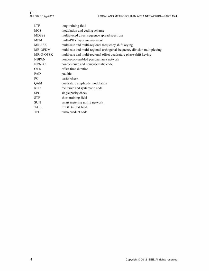
LTF long training field
MCS modulation and coding scheme
MDSSS multiplexed direct sequence spread spectrum
MPM multi-PHY layer management
MR-FSK multi-rate and multi-regional frequency shift keying
MR-OFDM multi-rate and multi-regional orthogonal frequency division multiplexing
MR-O-QPSK multi-rate and multi-regional offset quadrature phase-shift keying
NBPAN nonbeacon-enabled personal area network
NRNSC nonrecursive and nonsystematic code
OTD offset time duration
PAD pad bits
PC parity check
QAM quadrature amplitude modulation
RSC recursive and systematic code
SPC single parity check
STF short training field
SUN smart metering utility network
TAIL PPDU tail bit field
TPC turbo product code
4 Copyright © 2012 IEEE. All rights reserved.
IEEEWIRELESS MAC AND PHY SPECIFICATIONS FOR LR-WPANS—AMENDMENT 3 Std 802.15.4g-2012
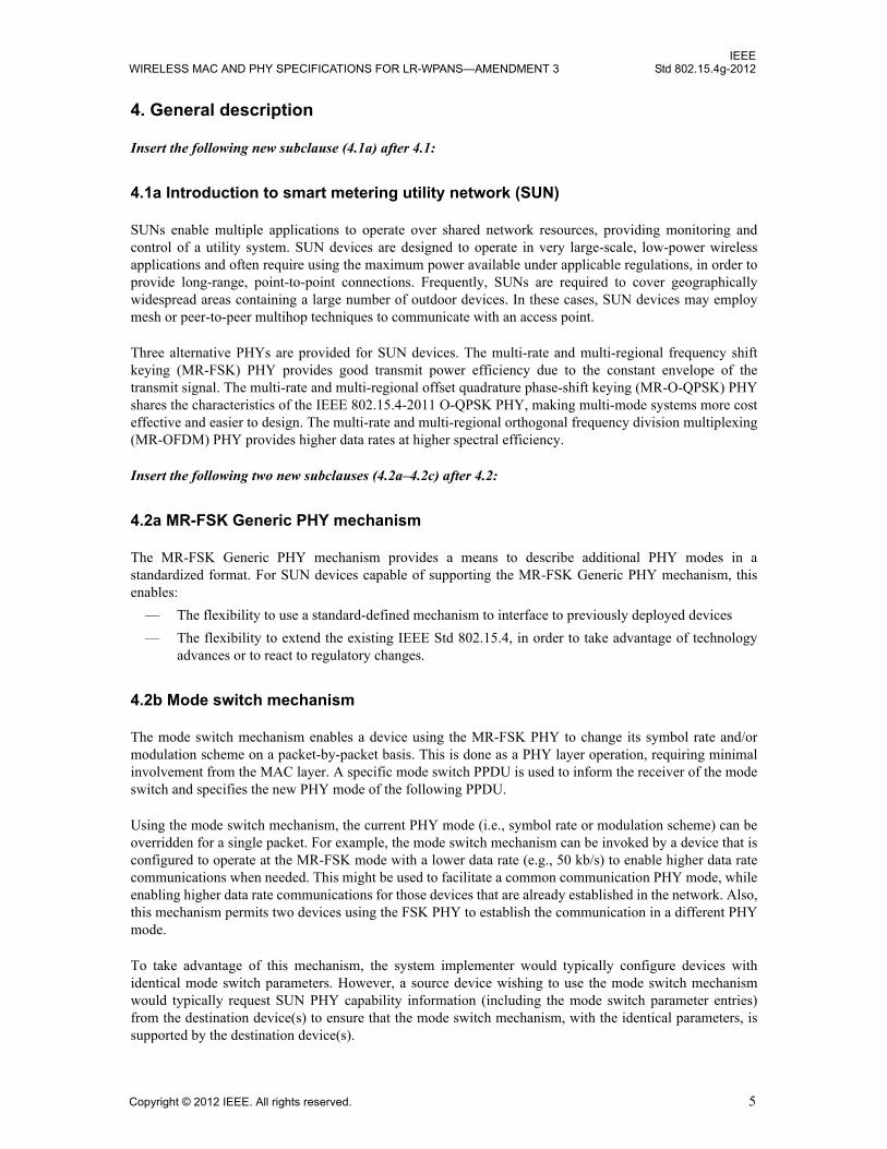
4. General description
Insert the following new subclause (4.1a) after 4.1:
4.1a Introduction to smart metering utility network (SUN)
SUNs enable multiple applications to operate over shared network resources, providing monitoring and control of a utility system. SUN devices are designed to operate in very large-scale, low-power wireless applications and often require using the maximum power available under applicable regulations, in order to provide long-range, point-to-point connections. Frequently, SUNs are required to cover geographically widespread areas containing a large number of outdoor devices. In these cases, SUN devices may employ mesh or peer-to-peer multihop techniques to communicate with an access point.
Three alternative PHYs are provided for SUN devices. The multi-rate and multi-regional frequency shift keying (MR-FSK) PHY provides good transmit power efficiency due to the constant envelope of the transmit signal. The multi-rate and multi-regional offset quadrature phase-shift keying (MR-O-QPSK) PHY shares the characteristics of the IEEE 802.15.4-2011 O-QPSK PHY, making multi-mode systems more cost effective and easier to design. The multi-rate and multi-regional orthogonal frequency division multiplexing (MR-OFDM) PHY provides higher data rates at higher spectral efficiency.
Insert the following two new subclauses (4.2a–4.2c) after 4.2:
4.2a MR-FSK Generic PHY mechanism
The MR-FSK Generic PHY mechanism provides a means to describe additional PHY modes in a standardized format. For SUN devices capable of supporting the MR-FSK Generic PHY mechanism, this enables:
— The flexibility to use a standard-defined mechanism to interface to previously deployed devices
— The flexibility to extend the existing IEEE Std 802.15.4, in order to take advantage of technology advances or to react to regulatory changes.
4.2b Mode switch mechanism
The mode switch mechanism enables a device using the MR-FSK PHY to change its symbol rate and/or modulation scheme on a packet-by-packet basis. This is done as a PHY layer operation, requiring minimal involvement from the MAC layer. A specific mode switch PPDU is used to inform the receiver of the mode switch and specifies the new PHY mode of the following PPDU.
Using the mode switch mechanism, the current PHY mode (i.e., symbol rate or modulation scheme) can be overridden for a single packet. For example, the mode switch mechanism can be invoked by a device that is configured to operate at the MR-FSK mode with a lower data rate (e.g., 50 kb/s) to enable higher data rate communications when needed. This might be used to facilitate a common communication PHY mode, while enabling higher data rate communications for those devices that are already established in the network. Also, this mechanism permits two devices using the FSK PHY to establish the communication in a different PHY mode.
To take advantage of this mechanism, the system implementer would typically configure devices with identical mode switch parameters. However, a source device wishing to use the mode switch mechanism would typically request SUN PHY capability information (including the mode switch parameter entries) from the destination device(s) to ensure that the mode switch mechanism, with the identical parameters, is supported by the destination device(s).
Copyright © 2012 IEEE. All rights reserved. 5
IEEEStd 802.15.4g-2012 LOCAL AND METROPOLITAN AREA NETWORKS—PART 15.4:
4.2c Multi-PHY management (MPM) of the SUN WPAN
Multiple, different SUN PHYs can operate in the same location and within the same frequency band. In order to mitigate interference, a multi-PHY management (MPM) scheme is specified for SUNs to facilitate inter-PHY coexistence. For this purpose, the MPM scheme facilitates interoperability and negotiation among potential coordinators with different PHYs by permitting a potential coordinator to detect an operating network during its discovery phase using the common signaling mode (CSM) appropriate to the band being used, as defined in Table 69a. The MPM procedure can be used in conjunction with the clear channel assessment (CCA) mechanism to provide coexistence.
6 Copyright © 2012 IEEE. All rights reserved.

IEEEWIRELESS MAC AND PHY SPECIFICATIONS FOR LR-WPANS—AMENDMENT 3 Std 802.15.4g-2012
5. MAC protocol
5.1 MAC functional description
Insert the following new paragraph before the last paragraph of 5.1:
For the MR-FSK PHY, the symbol duration used for MAC and PHY timing parameters, shown in Table 0, shall be the symbol duration of operating mode #1 specified in Table 134 and Table 135. For the MR-OFDM PHY, the symbol duration used for MAC timing parameters (macLIFSPeriod and macSIFSPeriod) shall be the symbol duration of MR-FSK operating mode #1 specified in Table 134 and Table 135, and the PHY symbol duration is defined in 18.2 and is to be used for aTurnaroundTime, macAckWaitDuration, and aCCATime. For the MR-O-QPSK PHY, the meaning of a symbol duration is described in 18.3.2.14.
5.1.1 Channel access
Insert the following new subclause (5.1.1.2a) after 5.1.1.2:
5.1.1.2a Enhanced beacon (EB) timing for MPM procedure
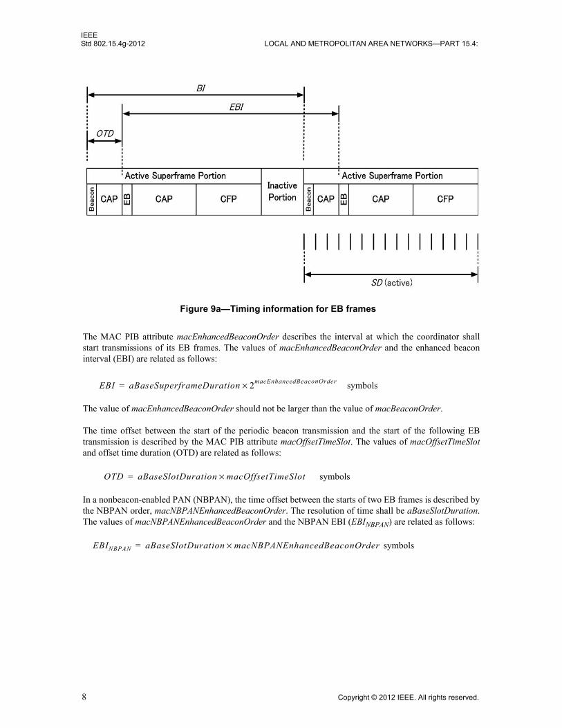
In a beacon-enabled PAN, a SUN device operating as a coordinator transmits an enhanced beacon (EB) containing a Coexistence Specification information element (IE) at fixed intervals, in addition to the usual periodic beacons. Figure 9a shows the EB timing for beacon-enabled PANs.
Table 0—MR-FSK symbol duration used for MAC and PHY timing parameters
Frequency band (MHz) MR-FSK symbol duration used for MAC and PHY timing parameters (µs)
169.400–169.475 (Europe) 208+1/3
450–470 (US FCC Part 22/90) 104+1/6
470–510 (China) 20
779–787 (China) 20
863–870 (Europe) 20
896–901 (US FCC Part 90) 100
901–902 (US FCC Part 24) 100
902–928 (US ISM) 20
917–923.5 (Korea) 20
928–960 (US FCC Part 22/24/90/101) 100
920–928 (Japan) 20
950–958 (Japan) 20
1427–1518 (US FCC Part 90)/(Canada SRSP 301.4)
100
2400–2483.5 (Worldwide) 20
Copyright © 2012 IEEE. All rights reserved. 7
IEEEStd 802.15.4g-2012 LOCAL AND METROPOLITAN AREA NETWORKS—PART 15.4:
The MAC PIB attribute macEnhancedBeaconOrder describes the interval at which the coordinator shall start transmissions of its EB frames. The values of macEnhancedBeaconOrder and the enhanced beacon interval (EBI) are related as follows:
symbols
The value of macEnhancedBeaconOrder should not be larger than the value of macBeaconOrder.
The time offset between the start of the periodic beacon transmission and the start of the following EB transmission is described by the MAC PIB attribute macOffsetTimeSlot. The values of macOffsetTimeSlotand offset time duration (OTD) are related as follows:
symbols
In a nonbeacon-enabled PAN (NBPAN), the time offset between the starts of two EB frames is described by the NBPAN order, macNBPANEnhancedBeaconOrder. The resolution of time shall be aBaseSlotDuration. The values of macNBPANEnhancedBeaconOrder and the NBPAN EBI (EBINBPAN) are related as follows:
symbols
Figure 9a—Timing information for EB frames
EBI aBaseSuperframeDuration 2macEnhancedBeaconOrder×=
OTD aBaseSlotDuration macOffsetTimeSlot×=
EBINBPAN aBaseSlotDuration macNBPANEnhancedBeaconOrder×=
8 Copyright © 2012 IEEE. All rights reserved.
IEEEWIRELESS MAC AND PHY SPECIFICATIONS FOR LR-WPANS—AMENDMENT 3 Std 802.15.4g-2012
5.1.2 Starting and maintaining PANs
5.1.2.3 Starting and realigning a PAN
5.1.2.3.1 Starting a PAN
Change the first paragraph of 5.1.2.3.1 as indicated:
A PAN should be started by an FFD only after having first performed a MAC sublayer reset, by issuing the MLME-RESET.request primitive, as described in 6.2.8.1, with the SetDefaultPIB parameter set to TRUE, an active channel scan, and a suitable PAN identifier selection. If the device is a SUN device operating as a coordinator, a passive scan for an EB Coexistence Specification IE, as described in 5.1.13, should take place prior to the active channel scan. The algorithm for selecting a suitable PAN identifier from the list of PAN descriptors returned from the active channel scan procedure is out of the scope of this standard. In addition, an FFD should set macShortAddress to a value less than 0xffff.
5.1.6 Transmission, reception, and acknowledgment
5.1.6.4 Use of acknowledgments and retransmissions
5.1.6.4.2 Acknowledgment
Insert the following new paragraph after the first paragraph of 5.1.6.4.2:
A SUN device may set the Enhanced Acknowledgment bit in the SUN PHY Capabilities IE, as described in 5.2.4.20b, to indicate that it supports enhanced acknowledgment frames.
Insert the following new subclause (5.1.13) after 5.1.12.5:
5.1.13 MPM procedure for inter-PHY coexistence
To facilitate interference avoidance among multiple SUNs utilizing different PHYs in the same location, all SUN coordinators operating at a duty cycle of more than 1% shall support the MPM procedures. In the MPM scheme, EBs are sent using the CSM, as defined in Table 69a. EBs used in the MPM procedures described here are EBs containing a Coexistence Specification IE.
The transmission of EBs should take place in all the channels defined for CSM, as described in Table 69a,that overlap with the channel(s) in operation. The scanning for EBs and the transmission of enhanced beacon requests (EBRs) should take place in all the channels defined for CSM that overlap with the channel of interest or at least two channels for PHY modes where the CSM requires frequency hopping.
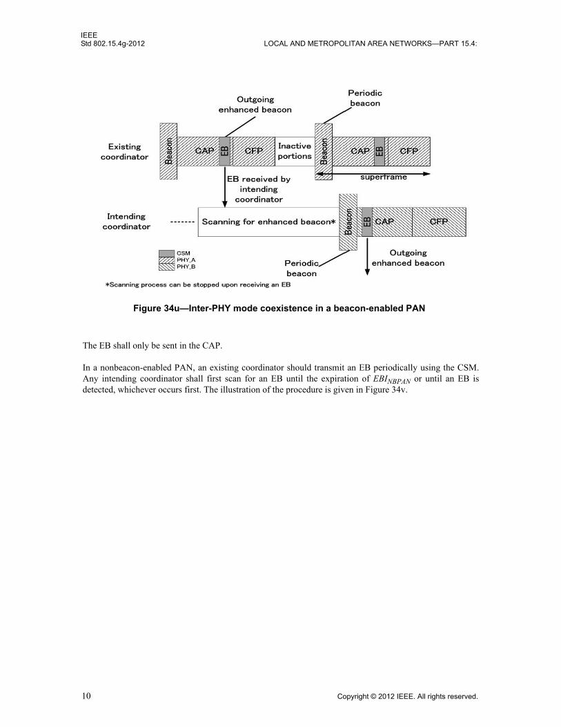
In a beacon-enabled PAN, an existing coordinator3 shall transmit an EB at a fixed interval by using CSM. Any intending coordinator4 shall first scan for an EB until the expiration of the EBI or until an EB is detected, whichever occurs first. If an intending coordinator detects an EB, it shall either occupy another channel, achieve synchronization with the existing PAN, or stop communication. While specific mechanisms to achieve synchronization between two PANs utilizing different PHY modes are implementation-dependent, the timing information applicable for synchronization purposes is specified in the EB. Figure 34u illustrates the MPM procedure.
3An existing coordinator is a coordinator currently operating a network.4An intending coordinator is a coordinator intending to start a separate network.
Copyright © 2012 IEEE. All rights reserved. 9
IEEEStd 802.15.4g-2012 LOCAL AND METROPOLITAN AREA NETWORKS—PART 15.4:
The EB shall only be sent in the CAP.
In a nonbeacon-enabled PAN, an existing coordinator should transmit an EB periodically using the CSM. Any intending coordinator shall first scan for an EB until the expiration of EBINBPAN or until an EB is detected, whichever occurs first. The illustration of the procedure is given in Figure 34v.
Figure 34u—Inter-PHY mode coexistence in a beacon-enabled PAN
10 Copyright © 2012 IEEE. All rights reserved.

IEEEWIRELESS MAC AND PHY SPECIFICATIONS FOR LR-WPANS—AMENDMENT 3 Std 802.15.4g-2012
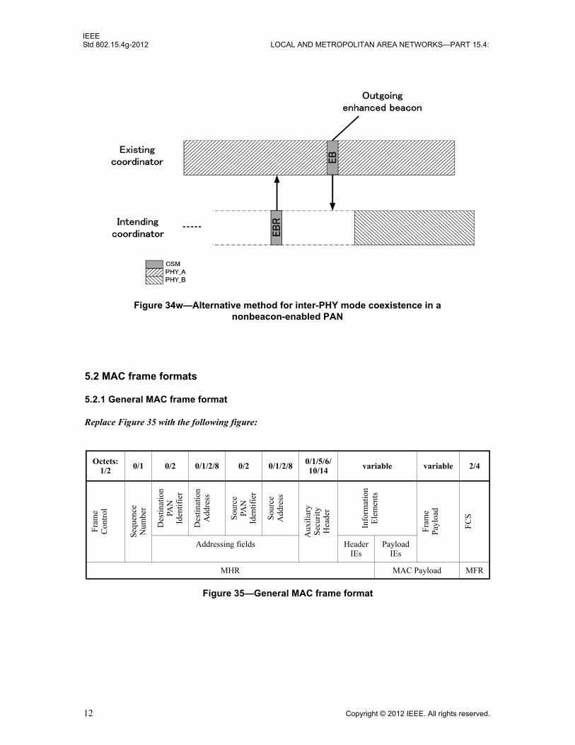
Alternatively, an EB may be obtained in an on-demand manner. In this case, an EBR containing the ID of the Coexistence Specification IE in the list of IE IDs is sent by the intending coordinator requesting an EB from the existing coordinator. Upon receiving an enhanced beacon request (EBR), the existing coordinator (or any other device within the same area that is capable of receiving and transmitting an EBR/EB using the CSM) may respond by sending an EB to the intending coordinator. The intending coordinator should transmit an EBR at least once every EBINBPAN. To increase the probability of receiving an EBR, the existing coordinator may periodically allocate a fraction of the CAP time to scan for the EBR in CSM. The illustration of the procedure is given in Figure 34w.
Figure 34v—Inter-PHY mode coexistence in a nonbeacon-enabled PAN
Copyright © 2012 IEEE. All rights reserved. 11
IEEEStd 802.15.4g-2012 LOCAL AND METROPOLITAN AREA NETWORKS—PART 15.4:
5.2 MAC frame formats
5.2.1 General MAC frame format
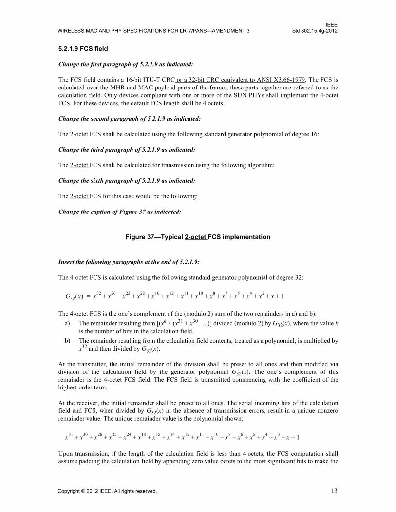
Replace Figure 35 with the following figure:
Octets:1/2 0/1 0/2 0/1/2/8 0/2 0/1/2/8
0/1/5/6/10/14 variable variable 2/4
Fra
me
Con
trol
Sequ
ence
Num
ber
Des
tinat
ion
PAN
Iden
tifie
r
Des
tinat
ion
Add
ress
Sou
rce
PAN
Iden
tifie
r
Sou
rce
Add
ress
Aux
ilia
ryS
ecur
ity
Hea
der
Info
rmat
ion
Ele
men
ts
Fra
me
Pay
load
FC
S
Addressing fields HeaderIEs
Payload IEs
MHR MAC Payload MFR
Figure 35—General MAC frame format
Figure 34w—Alternative method for inter-PHY mode coexistence in a nonbeacon-enabled PAN
12 Copyright © 2012 IEEE. All rights reserved.
IEEEWIRELESS MAC AND PHY SPECIFICATIONS FOR LR-WPANS—AMENDMENT 3 Std 802.15.4g-2012
5.2.1.9 FCS field
Change the first paragraph of 5.2.1.9 as indicated:
The FCS field contains a 16-bit ITU-T CRC or a 32-bit CRC equivalent to ANSI X3.66-1979. The FCS is calculated over the MHR and MAC payload parts of the frame.; these parts together are referred to as the calculation field. Only devices compliant with one or more of the SUN PHYs shall implement the 4-octet FCS. For these devices, the default FCS length shall be 4 octets.
Change the second paragraph of 5.2.1.9 as indicated:
The 2-octet FCS shall be calculated using the following standard generator polynomial of degree 16:
Change the third paragraph of 5.2.1.9 as indicated:
The 2-octet FCS shall be calculated for transmission using the following algorithm:
Change the sixth paragraph of 5.2.1.9 as indicated:
The 2-octet FCS for this case would be the following:
Change the caption of Figure 37 as indicated:
Insert the following paragraphs at the end of 5.2.1.9:
The 4-octet FCS is calculated using the following standard generator polynomial of degree 32:
The 4-octet FCS is the one’s complement of the (modulo 2) sum of the two remainders in a) and b):
a) The remainder resulting from [(xk × (x31 + x30 +...)] divided (modulo 2) by G32(x), where the value kis the number of bits in the calculation field.
b) The remainder resulting from the calculation field contents, treated as a polynomial, is multiplied by x32 and then divided by G32(x).
At the transmitter, the initial remainder of the division shall be preset to all ones and then modified via division of the calculation field by the generator polynomial G32(x). The one’s complement of this remainder is the 4-octet FCS field. The FCS field is transmitted commencing with the coefficient of the highest order term.
At the receiver, the initial remainder shall be preset to all ones. The serial incoming bits of the calculation field and FCS, when divided by G32(x) in the absence of transmission errors, result in a unique nonzero remainder value. The unique remainder value is the polynomial shown:
Upon transmission, if the length of the calculation field is less than 4 octets, the FCS computation shall assume padding the calculation field by appending zero value octets to the most significant bits to make the
Figure 37—Typical 2-octet FCS implementation
G32 x( ) x32 x26 x23 x22 x16 x12 x11 x10 x8 x7 x5 x4 x2 x 1+ + + + + + + + + + + + + +=
x31 x30 x26 x25 x24 x18 x15 x14 x12 x11 x10 x8 x6 x5 x4 x3 x 1+ + + + + + + + + + + + + + + + +
Copyright © 2012 IEEE. All rights reserved. 13
IEEEStd 802.15.4g-2012 LOCAL AND METROPOLITAN AREA NETWORKS—PART 15.4:
calculation field length exactly 4 octets; however, these pad bits shall not be transmitted. Upon reception, if the length of the calculation field is less than 4 octets, the received calculation field shall be appended with zero value octets to the most significant bits to make the calculation field length exactly 4 octets prior to computing the FCS for validation.
As an example, consider an acknowledgment frame with no payload and the following 3-byte MHR:
Prior to FCS computation, the zero padded calculation field is given as follows:
The 4-octet FCS for this case would be the following:
5.2.2 Format of individual frame types
5.2.2.1 Beacon frame format
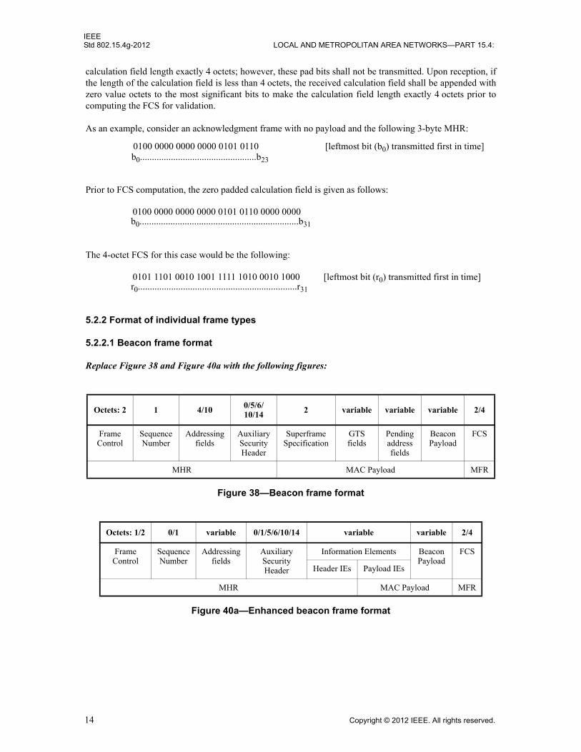
Replace Figure 38 and Figure 40a with the following figures:
Octets: 2 1 4/10 0/5/6/10/14 2 variable variable variable 2/4
FrameControl
SequenceNumber
Addressingfields
AuxiliarySecurityHeader
SuperframeSpecification
GTSfields
Pendingaddressfields
BeaconPayload
FCS
MHR MAC Payload MFR
Figure 38—Beacon frame format
Octets: 1/2 0/1 variable 0/1/5/6/10/14 variable variable 2/4
FrameControl
SequenceNumber
Addressingfields
AuxiliarySecurityHeader
Information Elements BeaconPayload
FCS
Header IEs Payload IEs
MHR MAC Payload MFR
Figure 40a—Enhanced beacon frame format
0100 0000 0000 0000 0101 0110 [leftmost bit (b0) transmitted first in time]b0.................................................b23
0100 0000 0000 0000 0101 0110 0000 0000 b0...................................................................b31
0101 1101 0010 1001 1111 1010 0010 1000 [leftmost bit (r0) transmitted first in time]r0...................................................................r31
14 Copyright © 2012 IEEE. All rights reserved.
IEEEWIRELESS MAC AND PHY SPECIFICATIONS FOR LR-WPANS—AMENDMENT 3 Std 802.15.4g-2012
5.2.2.2 Data frame format
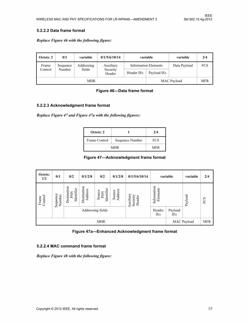
Replace Figure 46 with the following figure:
5.2.2.3 Acknowledgment frame format
Replace Figure 47 and Figure 47a with the following figures:
5.2.2.4 MAC command frame format
Replace Figure 48 with the following figure:
Octets: 2 0/1 variable 0/1/5/6/10/14 variable variable 2/4
Frame Control
SequenceNumber
Addressingfields
Auxiliary Security Header
Information Elements Data Payload FCS
Header IEs Payload IEs
MHR MAC Payload MFR
Figure 46—Data frame format
Octets: 2 1 2/4
Frame Control Sequence Number FCS
MHR MFR
Figure 47—Acknowledgment frame format
Octets:1/2
0/1 0/2 0/1/2/8 0/2 0/1/2/8 0/1/5/6/10/14 variable variable 2/4
Fra
me
Con
trol
Seq
uenc
eN
umbe
r
Des
tina
tion
PAN
Iden
tifi
er
Des
tina
tion
Add
ress
Sou
rce
PAN
Iden
tifi
er
Sou
rce
Add
ress
Aux
ilia
ryS
ecur
ity
Hea
der
Info
rmat
ion
Ele
men
ts
Pay
load
FC
S
Addressing fields HeaderIEs
PayloadIEs
MHR MAC Payload MFR
Figure 47a—Enhanced Acknowledgment frame format
Copyright © 2012 IEEE. All rights reserved. 15

IEEEStd 802.15.4g-2012 LOCAL AND METROPOLITAN AREA NETWORKS—PART 15.4:
5.2.4 Information element
5.2.4.5 MLME Information Elements
Insert the following new entries into Table 4d:
Insert the following new subclauses (5.2.4.20a–5.2.4.20d) after 5.2.4.20:
5.2.4.20a Coexistence Specification IE
The Coexistence Specification IE shall be formatted as illustrated in Figure 48oo. The leftmost seven octets are information for a beacon-enabled network, and the rightmost six octets are information for a nonbeacon-enabled network.
The Beacon Order field, Superframe Order field, and Final CAP Slot field are as specified in 5.2.2.1.2.
The Enhanced Beacon Order field specifies the transmission interval of the EB frames. See 5.1.1.2a for an explanation of the relationship between EB order and EBI.
The Offset Time Slot field specifies the time offset between the periodic beacon and the following EB, as described in 5.1.1.2a.
The CAP Backoff Offset field specifies the actual slot position in which the EB is transmitted due to the backoff procedure in the CAP.
Octets: 2 0/1 variable 0/1/5/6/10/14 variable 1 variable 2/4
FrameControl
SequenceNumber
Addressingfields
Auxiliary Security Header
Information Elements
CommandFrame
Identifier
CommandPayload
FCS
Header IEs
Payload IEs
MHR MAC Payload MFR
Figure 48—MAC command frame format
Table 4d—Sub-ID allocation for short form
Sub-IDvalue Content length Name Description
0x21 9 Coexistence SpecificationConveys the parameters that define the EB
0x22 Variable SUN PHY Capabilities Declares the PHY Capabilities of the device
0x23 16 MR-FSK Generic PHY Descriptor Declares one MR-FSK Generic PHY Descriptor
0x24 3 Mode Switch Parameter EntryDeclares one Mode Switch Parameter Entry
0x25–0x3f — Reserved —
16 Copyright © 2012 IEEE. All rights reserved.

IEEEWIRELESS MAC AND PHY SPECIFICATIONS FOR LR-WPANS—AMENDMENT 3 Std 802.15.4g-2012
The NBPAN Enhanced Beacon Order field specifies the transmission interval between consecutive EBs in the nonbeacon-enabled mode. The valid range for this field shall be 0–16383.
The Channel Page field shall contain a valid channel page value as defined in 8.1.2.10.
If the Beacon Order field is set to 15, the Superframe Order, Final CAP Slot, and Offset Time Slot fields shall be set to zero upon transmission and ignored upon reception. When generated in response to an EBR that contained a list of requested IEs, the content of the EB shall include the IEs corresponding to the requested IE IDs, as shown in Table 4j.
5.2.4.20b SUN device capabilities IE
The SUN device capabilities IE, shown in Figure 48pp, declares which SUN features a device supports.
The SUN Features field is encoded as a bitmap in the first octet of the IE Content field, as illustrated in Figure 48pp with a detailed description in Figure 48qq. A bit set to one indicates the feature is supported. Otherwise, the feature is not supported.
The bits of the SUN Features field are defined as follows:
— Bit 0 indicates support for enhanced acknowledgment frames, as described in 5.1.6.4.2.
— Bit 1 indicates support for data whitening, as described in 18.1.3.
— Bit 2 indicates support for interleaving, as described in 18.1.2.5.
Bit
#: 0
–3
4–7
8–11
12–1
5
16–1
9
20–2
3
24–5
5
56–7
1
Bea
con
Ord
er
Sup
erfr
ame
Ord
er
Fin
alC
AP
Slo
t
Enh
ance
dB
eaco
n O
rder
Off
set
Tim
e S
lot
CA
PB
acko
ff
Off
set
Cha
nnel
Pag
e
NB
PAN
Enh
ance
dB
eaco
n O
rder
Figure 48oo—Format of the Coexistence Specification IE
Table 4j— EBR IE per enabled attribute
PIB attribute IE type IEs to include
macMPMIE MLME payload Coexistence Specification IE (as defined in 5.2.4.20a)
Octets: 1 2 Variable
SUN Features Frequency Bands Supported PHY Type Descriptor(s)
Figure 48pp—SUN device capabilities IE format
Copyright © 2012 IEEE. All rights reserved. 17

IEEEStd 802.15.4g-2012 LOCAL AND METROPOLITAN AREA NETWORKS—PART 15.4:
— Bit 3 indicates support for start-of-frame delimiter (SFD) Group 1, as described in 18.1.1.2.
— Bit 4 indicates support for nonrecursive and nonsystematic code (NRNSC) forward error correction (FEC), as described in 18.1.2.4.
— Bit 5 indicates support for recursive and systematic code (RSC) forward error correction (FEC), as described in 18.1.2.4.
— Bit 6 indicates support for the mode switch mechanism, as described in 18.1.4.
The Frequency Bands Supported field is a bitmap indexed by the frequency band identifier values given in Table 68f. The least significant bit of the bitmap corresponds to frequency band identifier zero. A bit set to one indicates that the device supports operation in that frequency band; otherwise, it does not.
The PHY Type Descriptor field is shown in Figure 48rr.
The PHY Type field contains an unsigned integer whose value identifies a PHY Type defined in Table 4k.
The All Frequency Bands field indicates whether the optional Specific Frequency Bands field is present. If the All Frequency Bands field is set to one, the optional Specific Frequency Bands field is absent and the PHY Type is supported in all frequency bands declared in the Frequency Bands Supported field of the SUN device capabilities IE. If the All Frequency Bands field is set to zero, the optional Specific Frequency Bands field is present and the PHY Type is only supported in the frequency bands declared in the Specific Frequency Bands field of this PHY Type Descriptor.
The PHY Modes Supported field is a bitmap indicating which PHY modes are supported for the PHY Type. The PHY modes for each possible PHY Type are defined in Table 4l, Table 4m, Table 4n, Table 4o, Table 4p, and Table 4q. A bit set to one in bit bn of the PHY Mode ID bitmap indicates that the PHY Mode with ID n in the table of PHY Modes corresponding to the PHY Type is supported; otherwise, it is not supported.
The optional Specific Frequency Bands field is encoded in the same manner as the Frequency Bands Supported field of the SUN device capabilities IE.
Octets: 1
Bit #: 0 1 2 3 4 5 6 7
Enhanced ACK Data Whitening
Interleaving SFD G1 NRNSC FEC RSC FEC Mode Switch
Reserved
Figure 48qq—SUN Features field format
Octets: 2 2
Bit #: 0–3 4 5–15 0–15
PHY Type All Frequency Bands PHY Modes Supported(PHY Mode ID bitmap:
b0…b10)
Specific Frequency Bands(only present if All Frequency Bands = 0)
Figure 48rr—PHY Type Descriptor field format
18 Copyright © 2012 IEEE. All rights reserved.

IEEEWIRELESS MAC AND PHY SPECIFICATIONS FOR LR-WPANS—AMENDMENT 3 Std 802.15.4g-2012
Filtered FSK PHY modes are defined in Table 4l and Table 4m. For additional information on Filtered FSK,
see 18.1.2.
O-QPSK PHY modes are defined in Table 4n, Table 4o, and Table 4p.
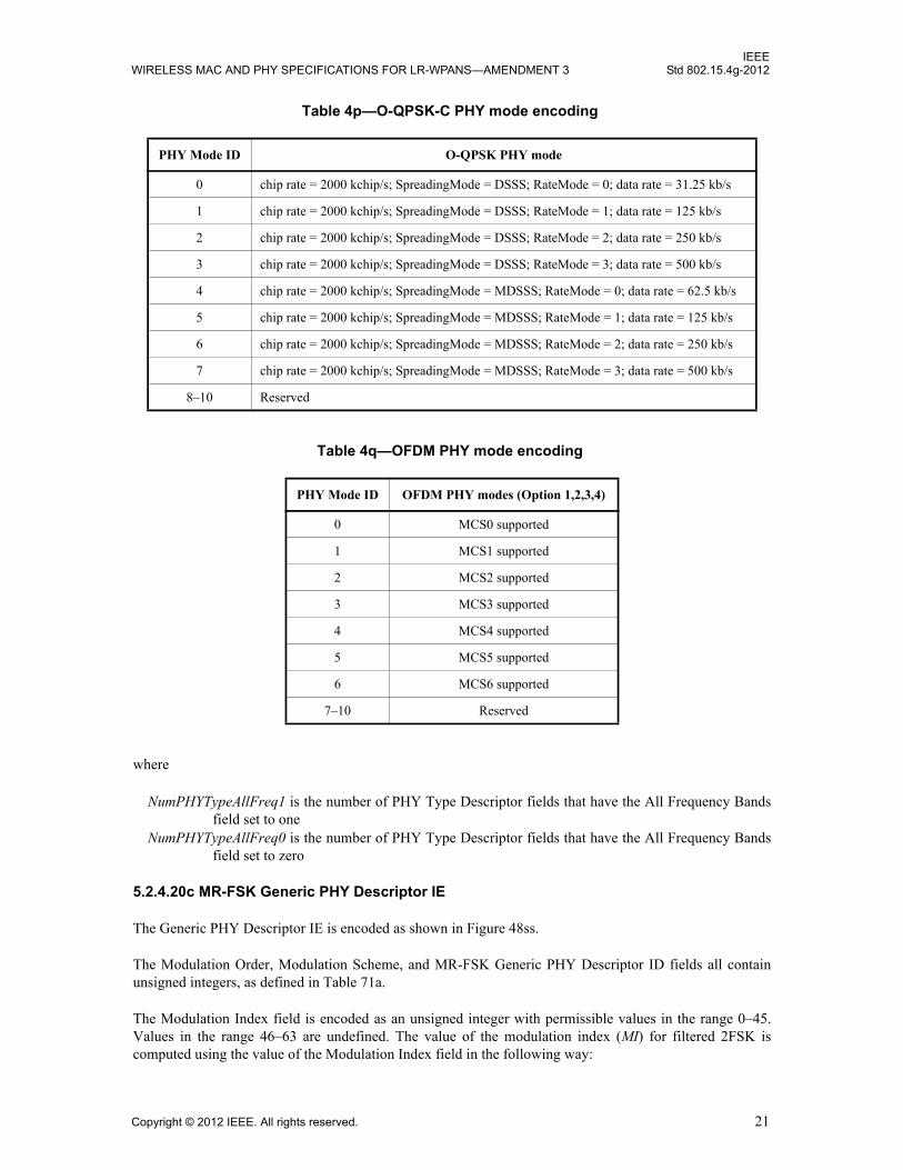
For each OFDM option, the supported MCSs are defined in Table 4q.
In each encoding of PHY modes in the PHY Type Descriptor field, a bit set to one in a bit position corresponding to a given modulation scheme in Table 4l, Table 4m, Table 4n, Table 4o, Table 4p, and Table 4q indicates the PHY mode for that modulation scheme is supported. A value of zero similarly indicates that the PHY mode is not supported.
Table 4k—Modulation scheme encoding
PHY type Modulation scheme
0 Filtered FSK-A
1 Filtered FSK-B
2 O-QPSK-A
3 O-QPSK-B
4 O-QPSK-C
5 OFDM Option 1
6 OFDM Option 2
7 OFDM Option 3
8 OFDM Option 4
9–15 Reserved
Table 4l—Filtered FSK-A PHY mode encoding
PHY Mode ID Narrowband FSK PHY mode
0 4.8 kb/s; Filtered 2FSK; mod index = 1.0; channel spacing = 12.5 kHz
1 9.6 kb/s; Filtered 4FSK; mod index = 0.33; channel spacing = 12.5 kHz
2 10 kb/s; Filtered 2FSK; mod index = 0.5; channel spacing = 12.5 kHz
3 20 kb/s; Filtered 2FSK; mod index = 0.5; channel spacing = 12.5 kHz
4 40 kb/s; Filtered 2FSK; mod index = 0.5; channel spacing = 12.5 kHz
5 4.8 kb/s; Filtered 2FSK; mod index = 0.5; channel spacing = 12.5 kHz
6 2.4 kb/s; Filtered 2FSK; mod index = 2.0; channel spacing = 12.5 kHz
7 9.6 kb/s; Filtered 4FSK; mod index = 0.33; channel spacing = 12.5 kHz
8–10 Reserved
Copyright © 2012 IEEE. All rights reserved. 19

IEEEStd 802.15.4g-2012 LOCAL AND METROPOLITAN AREA NETWORKS—PART 15.4:
The value of the SUN PHY Capabilities IE length field is computed as follows:
Length = 1 + 2 + 2 × NumPHYTypeAllFreq1 + 4 × NumPHYTypeAllFreq0
Table 4m—Filtered FSK-B PHY mode encoding
PHY Mode ID FSK PHY mode
0 50 kb/s; Filtered 2FSK; mod index = 1.0; channel spacing = 200 kHz
1 100 kb/s; Filtered 2FSK; mod index = 1.0; channel spacing = 400 kHz
2 150 kb/s; Filtered 2FSK; mod index = 0.5; channel spacing = 400 kHz
3 200 kb/s; Filtered 2FSK; mod index = 0.5; channel spacing = 400 kHz
4 200 kb/s; Filtered 4FSK; mod index = 0.33; channel spacing = 400 kHz
5 200 kb/s; Filtered 2FSK; mod index = 1.0; channel spacing = 600 kHz
6 400 kb/s; Filtered 4FSK; mod index = 0.33; channel spacing = 600 kHz
7–10 Reserved
Table 4n—O-QPSK-A PHY mode encoding
PHY Mode ID Narrowband O-QPSK PHY mode
0 chip rate = 100 kchip/s; SpreadingMode = DSSS; RateMode = 0; data rate = 6.25 kb/s
1 chip rate = 100 kchip/s; SpreadingMode = DSSS; RateMode = 1; data rate = 12.5 kb/s
2 chip rate = 100 kchip/s; SpreadingMode = DSSS; RateMode = 2; data rate = 25 kb/s
3 chip rate = 100 kchip/s; SpreadingMode = DSSS; RateMode = 3; data rate = 50 kb/s
4–10 Reserved
Table 4o—O-QPSK-B PHY mode encoding
PHY Mode ID O-QPSK PHY mode
0 chip rate = 1000 kchip/s; SpreadingMode = DSSS; RateMode = 0; data rate = 31.25 kb/s
1 chip rate = 1000 kchip/s; SpreadingMode = DSSS; RateMode = 1; data rate = 125 kb/s
2 chip rate = 1000 kchip/s; SpreadingMode = DSSS; RateMode = 2; data rate = 250 kb/s
3 chip rate = 1000 kchip/s; SpreadingMode = DSSS; RateMode = 3; data rate = 500 kb/s
4 chip rate = 1000 kchip/s; SpreadingMode = MDSSS; RateMode = 0; data rate = 62.5 kb/s
5 chip rate = 1000 kchip/s; SpreadingMode = MDSSS; RateMode = 1; data rate = 125 kb/s
6 chip rate = 1000 kchip/s; SpreadingMode = MDSSS; RateMode = 2; data rate = 250 kb/s
7 chip rate = 1000 kchip/s; SpreadingMode = MDSSS; RateMode = 3; data rate = 500 kb/s
8–10 Reserved
20 Copyright © 2012 IEEE. All rights reserved.
IEEEWIRELESS MAC AND PHY SPECIFICATIONS FOR LR-WPANS—AMENDMENT 3 Std 802.15.4g-2012
where
NumPHYTypeAllFreq1 is the number of PHY Type Descriptor fields that have the All Frequency Bands field set to one
NumPHYTypeAllFreq0 is the number of PHY Type Descriptor fields that have the All Frequency Bands field set to zero
5.2.4.20c MR-FSK Generic PHY Descriptor IE
The Generic PHY Descriptor IE is encoded as shown in Figure 48ss.
The Modulation Order, Modulation Scheme, and MR-FSK Generic PHY Descriptor ID fields all containunsigned integers, as defined in Table 71a.
The Modulation Index field is encoded as an unsigned integer with permissible values in the range 0–45. Values in the range 46–63 are undefined. The value of the modulation index (MI) for filtered 2FSK is computed using the value of the Modulation Index field in the following way:
Table 4p—O-QPSK-C PHY mode encoding
PHY Mode ID O-QPSK PHY mode
0 chip rate = 2000 kchip/s; SpreadingMode = DSSS; RateMode = 0; data rate = 31.25 kb/s
1 chip rate = 2000 kchip/s; SpreadingMode = DSSS; RateMode = 1; data rate = 125 kb/s
2 chip rate = 2000 kchip/s; SpreadingMode = DSSS; RateMode = 2; data rate = 250 kb/s
3 chip rate = 2000 kchip/s; SpreadingMode = DSSS; RateMode = 3; data rate = 500 kb/s
4 chip rate = 2000 kchip/s; SpreadingMode = MDSSS; RateMode = 0; data rate = 62.5 kb/s
5 chip rate = 2000 kchip/s; SpreadingMode = MDSSS; RateMode = 1; data rate = 125 kb/s
6 chip rate = 2000 kchip/s; SpreadingMode = MDSSS; RateMode = 2; data rate = 250 kb/s
7 chip rate = 2000 kchip/s; SpreadingMode = MDSSS; RateMode = 3; data rate = 500 kb/s
8–10 Reserved
Table 4q—OFDM PHY mode encoding
PHY Mode ID OFDM PHY modes (Option 1,2,3,4)
0 MCS0 supported
1 MCS1 supported
2 MCS2 supported
3 MCS3 supported
4 MCS4 supported
5 MCS5 supported
6 MCS6 supported
7–10 Reserved
Copyright © 2012 IEEE. All rights reserved. 21
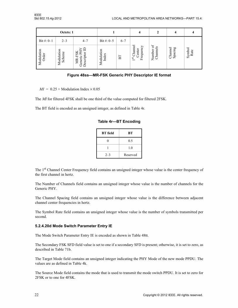
IEEEStd 802.15.4g-2012 LOCAL AND METROPOLITAN AREA NETWORKS—PART 15.4:
The MI for filtered 4FSK shall be one third of the value computed for filtered 2FSK.
The BT field is encoded as an unsigned integer, as defined in Table 4r.
The 1st Channel Center Frequency field contains an unsigned integer whose value is the center frequency of the first channel in hertz.
The Number of Channels field contains an unsigned integer whose value is the number of channels for the Generic PHY.
The Channel Spacing field contains an unsigned integer whose value is the difference between adjacent channel center frequencies in hertz.
The Symbol Rate field contains an unsigned integer whose value is the number of symbols transmitted per second.
5.2.4.20d Mode Switch Parameter Entry IE
The Mode Switch Parameter Entry IE is encoded as shown in Table 48tt.
The Secondary FSK SFD field value is set to one if a secondary SFD is present; otherwise, it is set to zero, as described in Table 71b.
The Target Mode field contains an unsigned integer indicating the PHY Mode of the new mode PPDU. The values are as defined in Table 4k.
The Source Mode field contains the mode that is used to transmit the mode switch PPDU. It is set to zero for 2FSK or to one for 4FSK.
Octets: 1 1 4 2 4 4
Bit #: 0–1 2–3 4–7 Bit #: 0–5 6–7
1st C
hann
elC
ente
rF
requ
ency
Num
ber
ofC
hann
els
Cha
nnel
Spa
cing
Sym
bol
Rat
e
Mod
ulat
ion
Ord
er
Mod
ulat
ion
Sch
eme
MR
-FS
KG
ener
ic P
HY
Des
crip
tor
ID
Mod
ulat
ion
Inde
x
BT
Figure 48ss—MR-FSK Generic PHY Descriptor IE format
Table 4r—BT Encoding
BT field BT
0 0.5
1 1.0
2–3 Reserved
MI 0.25 Modulation Index 0.05×+=
22 Copyright © 2012 IEEE. All rights reserved.

IEEEWIRELESS MAC AND PHY SPECIFICATIONS FOR LR-WPANS—AMENDMENT 3 Std 802.15.4g-2012
The Mode Switch Parameter Entry Index field contains an unsigned integer whose value is the index into the phyModeSwitchParameterEntries PIB attribute array containing the Mode Switch Parameter Entry.
The Settling Delay field contains an unsigned integer whose value times two is the settling delay in microseconds (0–510 μsec), as described in Table 71b.
The Secondary FSK Preamble Length field contains an unsigned integer whose value is the number of preamble repetitions for the secondary preamble when the new mode is MR-FSK, as described in Table 71b.
Octets: 1 1 1
Bit #: 0 1–4 5 6–7 Settling Delay
Secondary FSKPreamble Length
Secondary FSK SFD
Target Mode
Source Mode
Mode Switch Parameter
Entry Index
Figure 48tt—Mode Switch Parameter Entry IE format
Copyright © 2012 IEEE. All rights reserved. 23
IEEEStd 802.15.4g-2012 LOCAL AND METROPOLITAN AREA NETWORKS—PART 15.4:
6. MAC services
6.2 MAC management service
6.2.4 Communications notification primitives
6.2.4.1 MLME-BEACON-NOTIFY.indication
Insert the following new parameter at the end of the list in 6.2.4.1 (before the closing parenthesis):
Insert the following new row at the end of Table 16:
6.2.10 Primitives for channel scanning
6.2.10.1 MLME-SCAN.request
Insert the following new parameters at the end of the list in 6.2.10.1 (before the closing parenthesis):
Insert the following new rows at the end of Table 30:
6.2.12 Primitives for updating the superframe configuration
6.2.12.1 MLME-START.request
Insert the following new parameters at the end of the list in 6.2.12.1 (before the closing parenthesis)
Change Table 34 (the entire table is not shown) as indicated. The description of the parameter BeaconOrder is reproduced here to assist the reader. No changes are made to this description.
Table 16—MLME-BEACON-NOTIFY.indication parameters
Name Type Valid Range Description
CoexSpecification Set of octets As defined in 5.2.4.20a
The information on the multi-PHY management (MPM)
CoexSpecification
MPMScanDurationBPAN,MPMScanDurationNBPAN,MPMScan,MPMScanType
IEID,EnhancedBeaconOrder,OffsetTimeSlot,NBPANEnhancedBeaconOrder
24 Copyright © 2012 IEEE. All rights reserved.
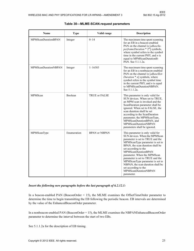
IEEEWIRELESS MAC AND PHY SPECIFICATIONS FOR LR-WPANS—AMENDMENT 3 Std 802.15.4g-2012
Insert the following new paragraphs before the last paragraph of 6.2.12.1:
In a beacon-enabled PAN (BeaconOrder < 15), the MLME examines the OffsetTimeOrder parameter to determine the time to begin transmitting the EB following the periodic beacon. EB intervals are determined by the value of the EnhancedBeaconOrder parameter.
In a nonbeacon-enabled PAN (BeaconOrder = 15), the MLME examines the NBPANEnhancedBeaconOrder parameter to determine the interval between the start of two EBs.
See 5.1.1.2a for the description of EB timing.
Table 30—MLME-SCAN.request parameters
Name Type Valid range Description
MPMScanDurationBPAN Integer 0–14 The maximum time spent scanning for an EB in a beacon-enabled PAN on the channel is [aBaseSu-perframeDuration * 2n] symbols, where symbol refers to the symbol time in the current PHY, and n is equal to MPMScanDurationB-PAN. See 5.1.1.2a.
MPMScanDurationNBPAN Integer 1–16383 The maximum time spent scanning for an EB in a nonbeacon-enabled PAN on the channel is [aBaseSlot-Duration * n] symbols, where symbol refers to the symbol time in the current PHY, and n is equal to MPMScanDurationNBPAN. See 5.1.1.2a.
MPMScan Boolean TRUE or FALSE This parameter is only valid for SUN devices. When set to TRUE, an MPM scan is invoked and the ScanDuration parameter shall be ignored. When set to FALSE, the scan duration shall be set according to the ScanDuration parameter; the MPMScanType, MPMScanDurationBPAN, and MPMScanDurationNBPAN parameters shall be ignored.
MPMScanType Enumeration BPAN or NBPAN This parameter is only valid for SUN devices. When the MPMScan parameter is set to TRUE and the MPMScanType parameter is set to BPAN, the scan duration shall be set according to the MPMScanDurationBPAN parameter. When the MPMScan parameter is set to TRUE and the MPMScanType parameter is set to NBPAN, the scan duration shall be set according to the MPMScanDurationNBPAN parameter.
Copyright © 2012 IEEE. All rights reserved. 25
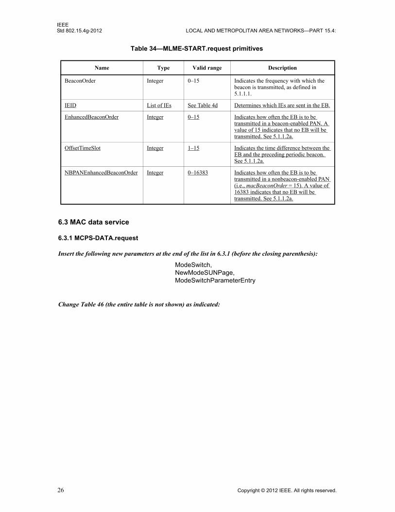
IEEEStd 802.15.4g-2012 LOCAL AND METROPOLITAN AREA NETWORKS—PART 15.4:
6.3 MAC data service
6.3.1 MCPS-DATA.request
Insert the following new parameters at the end of the list in 6.3.1 (before the closing parenthesis):
Change Table 46 (the entire table is not shown) as indicated:
Table 34—MLME-START.request primitives
Name Type Valid range Description
BeaconOrder Integer 0–15 Indicates the frequency with which the beacon is transmitted, as defined in 5.1.1.1.
IEID List of IEs See Table 4d Determines which IEs are sent in the EB.
EnhancedBeaconOrder Integer 0–15 Indicates how often the EB is to be transmitted in a beacon-enabled PAN. A value of 15 indicates that no EB will be transmitted. See 5.1.1.2a.
OffsetTimeSlot Integer 1–15 Indicates the time difference between the EB and the preceding periodic beacon. See 5.1.1.2a.
NBPANEnhancedBeaconOrder Integer 0–16383 Indicates how often the EB is to be transmitted in a nonbeacon-enabled PAN (i.e., macBeaconOrder = 15). A value of 16383 indicates that no EB will be transmitted. See 5.1.1.2a.
ModeSwitch,NewModeSUNPage, ModeSwitchParameterEntry
26 Copyright © 2012 IEEE. All rights reserved.

IEEEWIRELESS MAC AND PHY SPECIFICATIONS FOR LR-WPANS—AMENDMENT 3 Std 802.15.4g-2012
Table 46—MCPS-DATA.request parameters
Name Type Valid range Description
DataRate Integer 0–48 Indicates the data rate. For CSS PHYs, a value of one indicates 250 kb/s, while a value of two indicates 1 Mb/s. For UWB PHYs, values 1-4 are valid and are defined in 14.2.6.1.For the MR-OFDM PHY, values 1–7 are valid; each data rate value corresponds to the variable MCS{(data rate value)–1}, as described in Table 148. For the MR-O-QPSK PHY with SpreadingMode set to DSSS, values 1–4 are valid; each data rate value corresponds to the RateMode parameter plus one, as described in Table 166. For the MR-O-QPSK PHY with SpreadingMode set to MDSSS, values 5–8 are valid; each data rate value corresponds to the RateMode parameter plus five, as described in Table 167. For all other PHYs, the parameter is set to zero.
ModeSwitch Boolean TRUE or FALSE
A value of TRUE instructs the PHY entity to send a mode switch PPDU first and then a following PPDU that contains the PSDU using the associated mode switch parameters. The mode switch PPDU is transmitted using the PHY mode specified by phyCurrentSUNPageEntry. The PPDU containing the PSDU is transmitted using the PHY mode specified by NewModeSUNPageEntry.
A value of FALSE instructs the PHY to send the PSDU in a single PPDU using the PHY mode specified by phyCurrentSUNPageEntry on phyCurrentChannel.
This parameter is only valid for MR-FSK PHY, as described in 18.1.1.4 and 18.1.4.
NewModeSUNPageEntry Bitmap 0x00000000–0xffffffff
The modulation scheme and particular PHY mode for the new mode as defined by the channel page structure. The type and valid range are the same as defined for phyCurrentSUNPageEntry. This parameter is only valid if ModeSwitch = TRUE.
ModeSwitchParameterEntry Integer 0x00–0x03 The mode switch parameter entry specifies the index in the phyModeSwitchParameterEntries array for the ModeSwitchDescriptor to be used for this PHY mode switch. This parameter is only valid if ModeSwitch = TRUE.
Copyright © 2012 IEEE. All rights reserved. 27
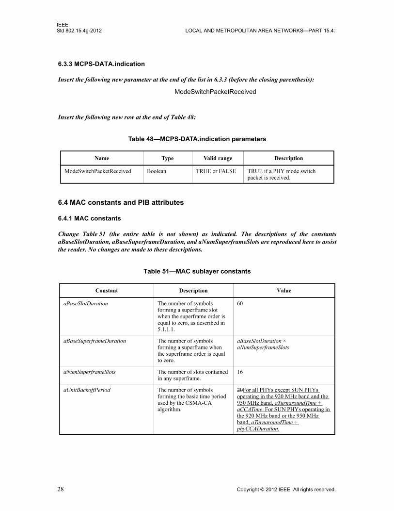
IEEEStd 802.15.4g-2012 LOCAL AND METROPOLITAN AREA NETWORKS—PART 15.4:
6.3.3 MCPS-DATA.indication
Insert the following new parameter at the end of the list in 6.3.3 (before the closing parenthesis):
Insert the following new row at the end of Table 48:
6.4 MAC constants and PIB attributes
6.4.1 MAC constants
Change Table 51 (the entire table is not shown) as indicated. The descriptions of the constantsaBaseSlotDuration, aBaseSuperframeDuration, and aNumSuperframeSlots are reproduced here to assist the reader. No changes are made to these descriptions.
Table 48—MCPS-DATA.indication parameters
Name Type Valid range Description
ModeSwitchPacketReceived Boolean TRUE or FALSE TRUE if a PHY mode switch packet is received.
Table 51—MAC sublayer constants
Constant Description Value
aBaseSlotDuration The number of symbols forming a superframe slot when the superframe order is equal to zero, as described in 5.1.1.1.
60
aBaseSuperframeDuration The number of symbols forming a superframe when the superframe order is equal to zero.
aBaseSlotDuration ×aNumSuperframeSlots
aNumSuperframeSlots The number of slots contained in any superframe.
16
aUnitBackoffPeriod The number of symbols forming the basic time period used by the CSMA-CA algorithm.
20For all PHYs except SUN PHYs operating in the 920 MHz band and the 950 MHz band, aTurnaroundTime + aCCATime. For SUN PHYs operating in the 920 MHz band or the 950 MHz band, aTurnaroundTime + phyCCADuration.
ModeSwitchPacketReceived
28 Copyright © 2012 IEEE. All rights reserved.
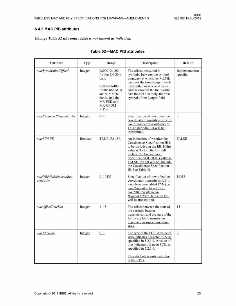
IEEEWIRELESS MAC AND PHY SPECIFICATIONS FOR LR-WPANS—AMENDMENT 3 Std 802.15.4g-2012
6.4.2 MAC PIB attributes
Change Table 52 (the entire table is not shown) as indicated:
Table 52—MAC PIB attributes
Attribute Type Range Description Default
macSyncSymbolOffset† Integer 0x000–0x100 for the 2.4 GHz band
0x000–0x400 for the 868 MHz and 915 MHz bands, and the MR-FSK and MR-OFDM PHYs
The offset, measured in symbols, between the symbol boundary at which the MLME captures the timestamp of each transmitted or received frame, and the onset of the first symbol past the SFD, namely, the first symbol of the Length field.
Implementationspecific
macEnhancedBeaconOrder Integer 0–15 Specification of how often the coordinator transmits an EB. If macEnhancedBeaconOrder = 15, no periodic EB will be transmitted.
0
macMPMIE Boolean TRUE, FALSE An indication of whether the Coexistence Specification IE is to be included in the EB. If this value is TRUE, the EB will include the Coexistence Specification IE. If this value is FALSE, the EB will not include the Coexistence Specification IE. See Table 4j.
FALSE
macNBPANEnhancedBea-conOrder
Integer 0–16383 Specification of how often the coordinator transmits an EB in a nonbeacon-enabled PAN (i.e., macBeaconOrder = 15). If macNBPANEnhanced-BeaconOrder =16383, no EB will be transmitted.
16383
macOffsetTimeSlot Integer 1–15 The offset between the start of the periodic beacon transmission and the start of the following EB transmission expressed in superframe time slots.
15
macFCSType Integer 0–1 The type of the FCS. A value of zero indicates a 4-octet FCS, as specified in 5.2.1.9. A value of one indicates a 2-octet FCS, as specified in 5.2.1.9.
This attribute is only valid for SUN PHYs.
0
Copyright © 2012 IEEE. All rights reserved. 29

IEEEStd 802.15.4g-2012 LOCAL AND METROPOLITAN AREA NETWORKS—PART 15.4:
6.4.3 Calculating PHY dependent MAC PIB values
Change the first paragraph of 6.4.3 as indicated:
The read-only attribute macAckWaitDuration is dependent on a combination of constants and PHY PIB attributes. The PHY PIB attributes are listed in Table 71. The formula for relating the constants and attributes for all PHYs except the SUN PHYs is:
macAckWaitDuration =
Insert the following new paragraphs after the first paragraph of 6.4.3:
The formula for relating the constants and attributes for the MR-FSK PHY is:
macAckWaitDuration =
The formula for relating the constants and attributes for the MR-OFDM PHY is:
macAckWaitDuration =
The formula for relating the constants and attributes for the MR-O-QPSK PHY is:
macAckWaitDuration =
where LENGTH is the length, in octets, of the acknowledgment frame, and phyPSDUDuration(LENGTH) is given in 18.3.2.14.
aUnitBackoffPeriod aTurnaroundTime phySHRDuration ceiling 6 phySymbolsPerOctet×( )+ + +
aUnitBackoffPeriod aTurnaroundTime phySHRDuration ceiling 9 phySymbolsPerOctet×( )+ + +
aUnitBackoffPeriod aTurnaroundTime phySHRDuration phyPHRDuration ceiling 6 phySymbolsPerOctet×( )+ + + +
aUnitBackoffPeriod aTurnaroundTime phySHRDuration phyPHRDuration phyPSDUDuration LENGTH( )+ + + +
30 Copyright © 2012 IEEE. All rights reserved.
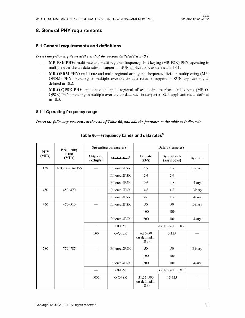
IEEEWIRELESS MAC AND PHY SPECIFICATIONS FOR LR-WPANS—AMENDMENT 3 Std 802.15.4g-2012
8. General PHY requirements
8.1 General requirements and definitions
Insert the following items at the end of the second bulleted list in 8.1:
— MR-FSK PHY: multi-rate and multi-regional frequency shift keying (MR-FSK) PHY operating in multiple over-the-air data rates in support of SUN applications, as defined in 18.1.
— MR-OFDM PHY: multi-rate and multi-regional orthogonal frequency division multiplexing (MR-OFDM) PHY operating in multiple over-the-air data rates in support of SUN applications, as defined in 18.2.
— MR-O-QPSK PHY: multi-rate and multi-regional offset quadrature phase-shift keying (MR-O-QPSK) PHY operating in multiple over-the-air data rates in support of SUN applications, as defined in 18.3.
8.1.1 Operating frequency range
Insert the following new rows at the end of Table 66, and add the footnotes to the table as indicated:
Table 66—Frequency bands and data ratesa
PHY(MHz)
Frequencyband
(MHz)
Spreading parameters Data parameters
Chip rate (kchip/s) Modulationb Bit rate
(kb/s)Symbol rate (ksymbol/s) Symbols
169 169.400–169.475 — Filtered 2FSK 4.8 4.8 Binary
Filtered 2FSK 2.4 2.4
Filtered 4FSK 9.6 4.8 4-ary
450 450–470 — Filtered 2FSK 4.8 4.8 Binary
Filtered 4FSK 9.6 4.8 4-ary
470 470–510 — Filtered 2FSK 50 50 Binary
100 100
Filtered 4FSK 200 100 4-ary
— OFDM As defined in 18.2
100 O-QPSK 6.25–50(as defined in
18.3)
3.125 —
780 779–787 — Filtered 2FSK 50 50 Binary
100 100
Filtered 4FSK 200 100 4-ary
— OFDM As defined in 18.2
1000 O-QPSK 31.25–500 (as defined in
18.3)
15.625 —
Copyright © 2012 IEEE. All rights reserved. 31
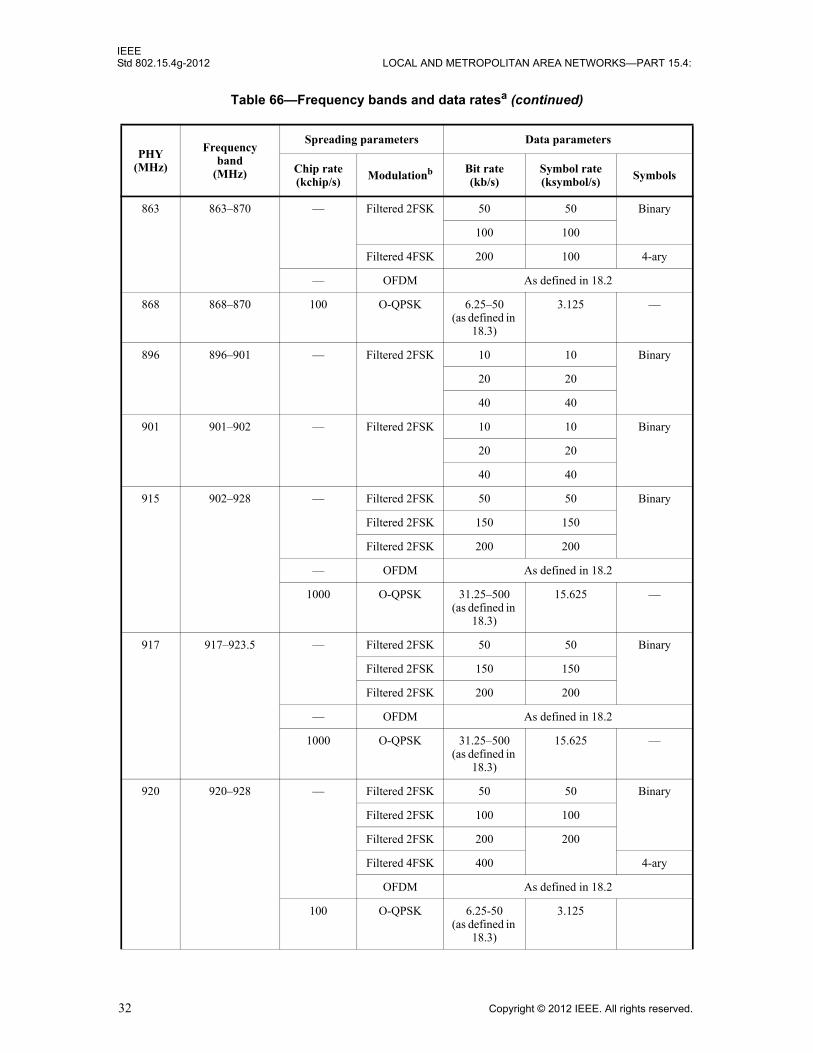
IEEEStd 802.15.4g-2012 LOCAL AND METROPOLITAN AREA NETWORKS—PART 15.4:
863 863–870 — Filtered 2FSK 50 50 Binary
100 100
Filtered 4FSK 200 100 4-ary
— OFDM As defined in 18.2
868 868–870 100 O-QPSK 6.25–50 (as defined in
18.3)
3.125 —
896 896–901 — Filtered 2FSK 10 10 Binary
20 20
40 40
901 901–902 — Filtered 2FSK 10 10 Binary
20 20
40 40
915 902–928 — Filtered 2FSK 50 50 Binary
Filtered 2FSK 150 150
Filtered 2FSK 200 200
— OFDM As defined in 18.2
1000 O-QPSK 31.25–500 (as defined in
18.3)
15.625 —
917 917–923.5 — Filtered 2FSK 50 50 Binary
Filtered 2FSK 150 150
Filtered 2FSK 200 200
— OFDM As defined in 18.2
1000 O-QPSK 31.25–500(as defined in
18.3)
15.625 —
920 920–928 — Filtered 2FSK 50 50 Binary
Filtered 2FSK 100 100
Filtered 2FSK 200 200
Filtered 4FSK 400 4-ary
OFDM As defined in 18.2
100 O-QPSK 6.25-50(as defined in
18.3)
3.125
Table 66—Frequency bands and data ratesa (continued)
PHY(MHz)
Frequencyband
(MHz)
Spreading parameters Data parameters
Chip rate (kchip/s) Modulationb Bit rate
(kb/s)Symbol rate (ksymbol/s) Symbols
32 Copyright © 2012 IEEE. All rights reserved.
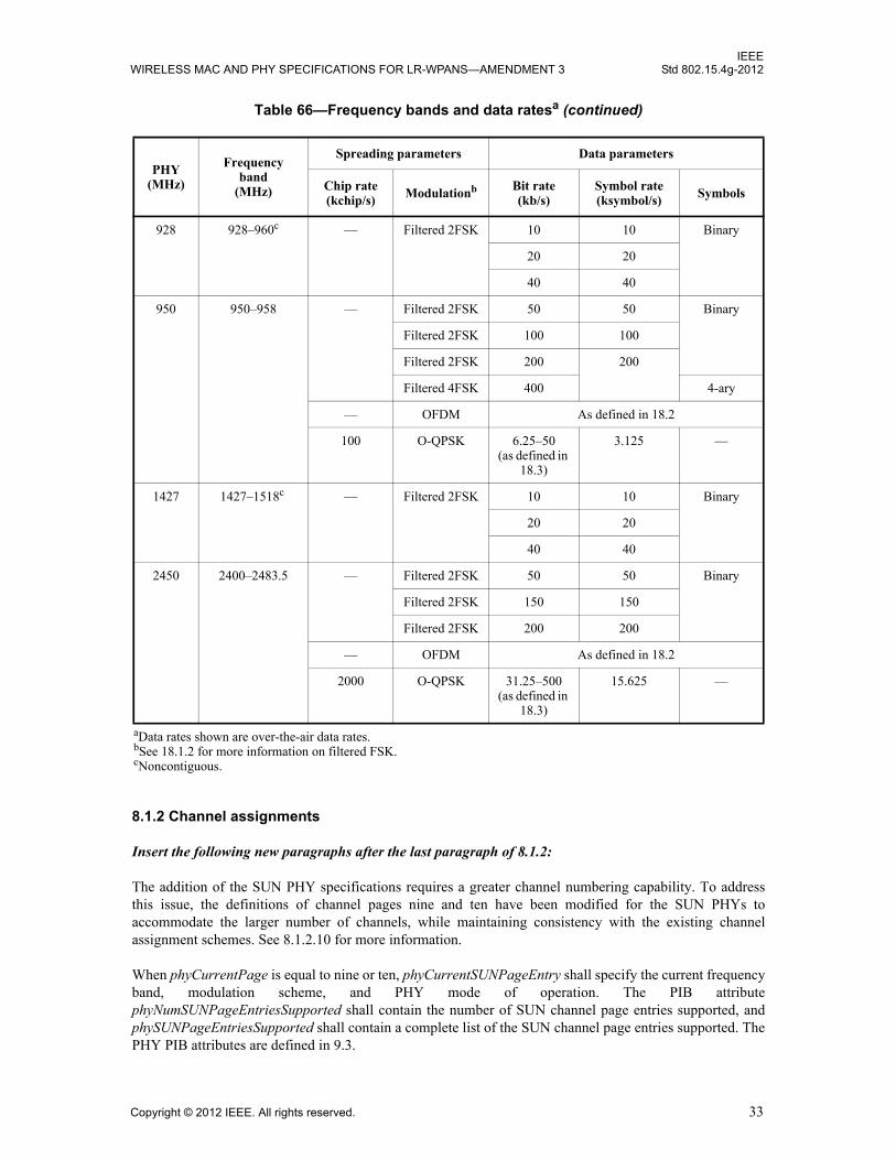
IEEEWIRELESS MAC AND PHY SPECIFICATIONS FOR LR-WPANS—AMENDMENT 3 Std 802.15.4g-2012
8.1.2 Channel assignments
Insert the following new paragraphs after the last paragraph of 8.1.2:
The addition of the SUN PHY specifications requires a greater channel numbering capability. To addressthis issue, the definitions of channel pages nine and ten have been modified for the SUN PHYs toaccommodate the larger number of channels, while maintaining consistency with the existing channelassignment schemes. See 8.1.2.10 for more information.
When phyCurrentPage is equal to nine or ten, phyCurrentSUNPageEntry shall specify the current frequencyband, modulation scheme, and PHY mode of operation. The PIB attributephyNumSUNPageEntriesSupported shall contain the number of SUN channel page entries supported, andphySUNPageEntriesSupported shall contain a complete list of the SUN channel page entries supported. ThePHY PIB attributes are defined in 9.3.
928 928–960c — Filtered 2FSK 10 10 Binary
20 20
40 40
950 950–958 — Filtered 2FSK 50 50 Binary
Filtered 2FSK 100 100
Filtered 2FSK 200 200
Filtered 4FSK 400 4-ary
— OFDM As defined in 18.2
100 O-QPSK 6.25–50 (as defined in
18.3)
3.125 —
1427 1427–1518c — Filtered 2FSK 10 10 Binary
20 20
40 40
2450 2400–2483.5 — Filtered 2FSK 50 50 Binary
Filtered 2FSK 150 150
Filtered 2FSK 200 200
— OFDM As defined in 18.2
2000 O-QPSK 31.25–500 (as defined in
18.3)
15.625 —
aData rates shown are over-the-air data rates.bSee 18.1.2 for more information on filtered FSK.cNoncontiguous.
Table 66—Frequency bands and data ratesa (continued)
PHY(MHz)
Frequencyband
(MHz)
Spreading parameters Data parameters
Chip rate (kchip/s) Modulationb Bit rate
(kb/s)Symbol rate (ksymbol/s) Symbols
Copyright © 2012 IEEE. All rights reserved. 33

IEEEStd 802.15.4g-2012 LOCAL AND METROPOLITAN AREA NETWORKS—PART 15.4:
8.1.2.1 Channel numbering for 780 MHz band
Insert the following new paragraph before the first paragraph of 8.1.2.1:
This subclause does not apply to the SUN PHY specifications. See 8.1.2.9 for an explanation of channelnumbering for the SUN PHYs.
8.1.2.2 Channel numbering for 868 MHz, 915 MHz, and 2450 MHz bands
Insert the following new paragraph before the first paragraph of 8.1.2.2:
This subclause does not apply to the SUN PHY specifications. See 8.1.2.9 for an explanation of channelnumbering for the SUN PHYs.
8.1.2.3 Channel numbering for 950 MHz PHYs
Insert the following new paragraph before the first paragraph of 8.1.2.3:
This subclause does not apply to the SUN PHY specifications. See 8.1.2.9 for an explanation of channelnumbering for the SUN PHYs.
Insert the following new subclauses (8.1.2.9–8.1.2.10.2) after 8.1.2.8:
8.1.2.9 Channel numbering for SUN PHYs
The channel center frequency ChanCenterFreq for all SUN PHYs, except the MR-O-QPSK PHY operatingin the 868–870 MHz band, shall be derived as follows:
where ChanCenterFreq0 is the first channel center frequency in MHz, ChanSpacing is the separationbetween adjacent channels in MHz, NumChan is the channel number from 0 to TotalNumChan–1, andTotalNumChan is the total number of channels for the available frequency band. The parametersChanSpacing, TotalNumChan, and ChanCenterFreq0 for different frequency bands and modulationschemes are specified in Table 68d.
Three channels are available for the MR-O-QPSK PHY operating in the 868–870 MHz band. The channelcenter frequency for each of these channels is shown in Table 68e.
8.1.2.10 Channel pages for SUN PHYs
Channel page nine is used to specify the standard-defined PHY operating modes, and channel page ten isused to specify the MR-FSK Generic-PHY-defined PHY modes. A device that implements more than onePHY operating mode, as described by channel page nine, may have multiple channel page nine entries in thephySUNPageEntriesSupported table. The channels are defined by phySUNChannelsSupported. The PHYPIB attributes are defined in 9.3.
The structures of channel pages nine and ten are shown in Figure 64a.
8.1.2.10.1 Channel page structure for standard-defined PHY modes
Channel page nine specifies each standard-defined SUN PHY operating mode supported by the device.
ChanCenterFreq ChanCenterFreq0 NumChan ChanSpacing×+=
34 Copyright © 2012 IEEE. All rights reserved.
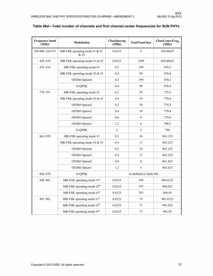
IEEEWIRELESS MAC AND PHY SPECIFICATIONS FOR LR-WPANS—AMENDMENT 3 Std 802.15.4g-2012
Table 68d—Total number of channels and first channel center frequencies for SUN PHYs
Frequency band(MHz) Modulation ChanSpacing
(MHz) TotalNumChan ChanCenterFreq0 (MHz)
169.400–169.475 MR-FSK operating mode #1 & #2 & #3
0.0125 6 169.40625
450–470 MR-FSK operating mode #1 & #2 0.0125 1599 450.00625
470–510 MR-FSK operating mode #1 0.2 199 470.2
MR-FSK operating mode #2 & #3 0.4 99 470.4
OFDM Option4 0.2 199 470.2
O-QPSK 0.4 99 470.4
779–787 MR-FSK operating mode #1 0.2 39 779.2
MR-FSK operating mode #2 & #3 0.4 19 779.4
OFDM Option4 0.2 39 779.2
OFDM Option3 0.4 19 779.4
OFDM Option2 0.8 9 779.8
OFDM Option1 1.2 6 780.2
O-QPSK 2 4 780
863–870 MR-FSK operating mode #1 0.2 34 863.125
MR-FSK operating mode #2 & #3 0.4 17 863.225
OFDM Option4 0.2 34 863.125
OFDM Option3 0.4 17 863.225
OFDM Option2 0.8 8 863.425
OFDM Option1 1.2 5 863.625
868–870 O-QPSK As defined in Table 68e
896–901 MR-FSK operating mode #1a 0.0125 399 896.0125
MR-FSK operating mode #2b 0.0125 397 896.025
MR-FSK operating mode #3c 0.0125 393 896.05
901–902 MR-FSK operating mode #1a 0.0125 79 901.0125
MR-FSK operating mode #2b 0.0125 77 901.025
MR-FSK operating mode #3c 0.0125 73 901.05
Copyright © 2012 IEEE. All rights reserved. 35

IEEEStd 802.15.4g-2012 LOCAL AND METROPOLITAN AREA NETWORKS—PART 15.4:
902–928 MR-FSK operating mode #1 0.2 129 902.2
MR-FSK operating mode #2 & #3 0.4 64 902.4
OFDM Option4 0.2 129 902.2
OFDM Option3 0.4 64 902.4
OFDM Option2 0.8 31 902.8
OFDM Option1 1.2 20 903.2
O-QPSK 2 12 904
917–923.5 OFDM Option4 0.2 32 917.1
OFDM Option3 0.4 16 917.3
OFDM Option2 0.8 8 917.5
OFDM Option1 1.2 5 917.9
MR-FSK operating mode #1 0.2 32 917.1
MR-FSK operating mode #2 & #3 0.4 16 917.3
O-QPSK 2 3 918.1
920–928 MR-FSK operating mode #1 0.2 38 920.6
MR-FSK operating mode #2 0.4 18 920.9
MR-FSK operating mode #3 & #4 0.6 12 920.8
OFDM Option4 0.2 39 920.2
OFDM Option3 0.4 19 920.4
OFDM Option2 0.8 9 920.8
OFDM Option1 1.2 6 921.2
O-QPSK 0.2 38 920.6
928–960 MR-FSK operating mode #1a 0.0125 2559 928.0125
MR-FSK operating mode #2b 0.0125 2557 928.025
MR-FSK operating mode #3c 0.0125 2553 928.05
950–958 MR-FSK operating mode #1 0.2 33 951
MR-FSK operating mode #2 0.4 16 951.1
MR-FSK operating mode #3 & #4 0.6 11 951.2
OFDM Option4 0.2 33 951
OFDM Option3 0.4 16 951.1
OFDM Option2 0.8 8 951.3
O-QPSK 0.4 16 951.1
Table 68d—Total number of channels and first channel center frequencies for SUN PHYs (continued)
Frequency band(MHz) Modulation ChanSpacing
(MHz) TotalNumChan ChanCenterFreq0 (MHz)
36 Copyright © 2012 IEEE. All rights reserved.

IEEEWIRELESS MAC AND PHY SPECIFICATIONS FOR LR-WPANS—AMENDMENT 3 Std 802.15.4g-2012
As shown in Figure 64a, channel page nine consists of the frequency band(s), modulation scheme(s), andPHY mode(s) to specify the SUN operating modes. The values used to define the frequency bands are the
1427–1518 MR-FSK operating mode #1a 0.0125 7279 1427.0125
MR-FSK operating mode #2b 0.0125 7277 1427.025
MR-FSK operating mode #3c 0.0125 7273 1427.05
2400–2483.5 MR-FSK operating mode #1 0.2 416 2400.2
MR-FSK operating mode #2 & #3 0.4 207 2400.4
OFDM Option4 0.2 416 2400.2
OFDM Option3 0.4 207 2400.4
OFDM Option2 0.8 97 2400.8
OFDM Option1 1.2 64 2401.2
O-QPSK 5 16 2405aTwo adjacent ChanSpacing(s) are aggregated to form an overlapping channel with bandwidth of 25 kHz.bFour adjacent ChanSpacing(s) are aggregated to form an overlapping channel with bandwidth of 50 kHz.cEight adjacent ChanSpacing(s) are aggregated to form an overlapping channel with bandwidth of 100 kHz.
Table 68e—Center frequencies for the MR-O-QPSK PHY operating in the 868–870 MHz band
NumChan ChanCenterFreq (MHz)
0 868.300
1 868.950
2 869.525
Channel page 9 Frequency band
(Table 68f)
Modulationscheme = Filtered FSK
(Table 68g)
List of FSK modes supported(Table 68h)
Modulationscheme = OFDM
(Table 68g)
OFDM Option1,2,3, or 4(Table 68i)
MCS values supported(for selected Option)
(Table 68j)
Modulationscheme = O-QPSK
(Table 68g)
Spreading mode(Table 68k)
Rate modes supported(Table 68k)
Channel page 10
MR-FSK Generic-PHY-defined PHY modes (as defined in 8.1.2.10.2)
Figure 64a—Channel page structure for channel pages nine and ten
Table 68d—Total number of channels and first channel center frequencies for SUN PHYs (continued)
Frequency band(MHz) Modulation ChanSpacing
(MHz) TotalNumChan ChanCenterFreq0 (MHz)
Copyright © 2012 IEEE. All rights reserved. 37
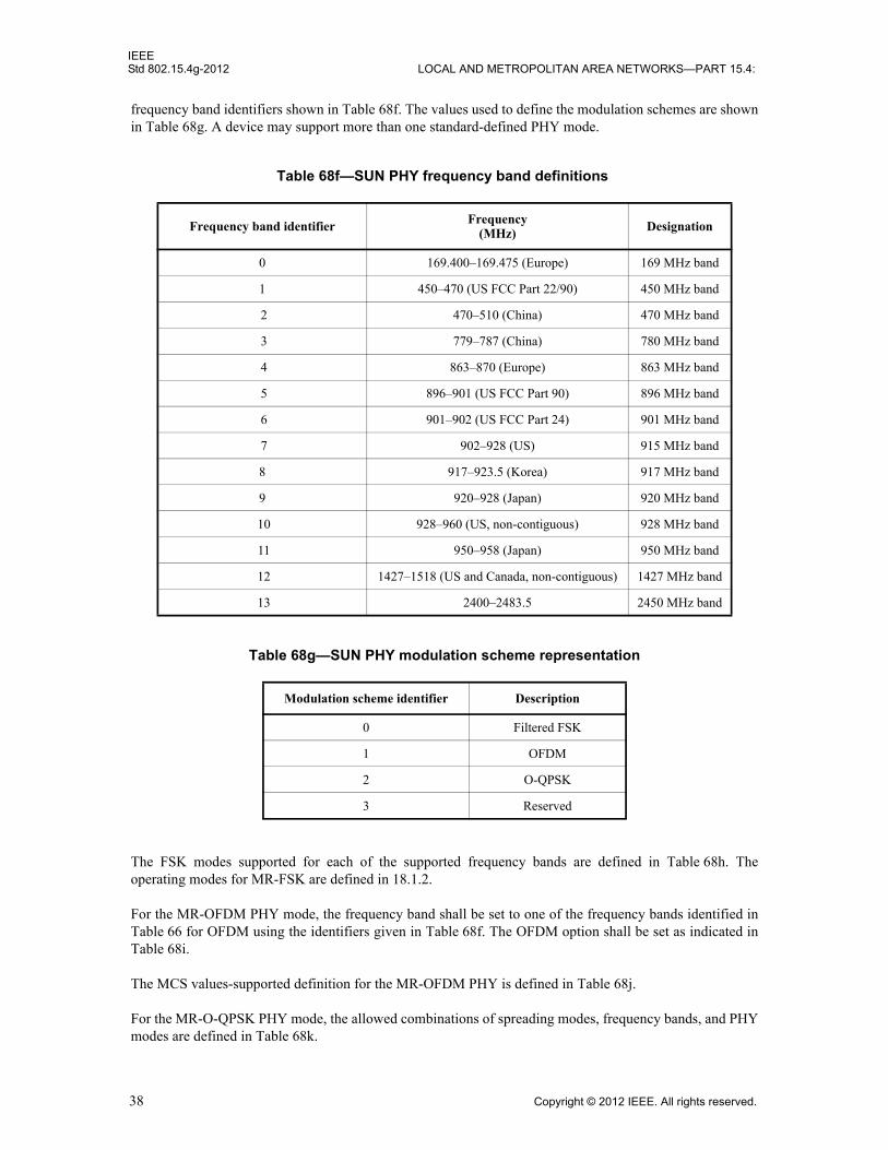
IEEEStd 802.15.4g-2012 LOCAL AND METROPOLITAN AREA NETWORKS—PART 15.4:
frequency band identifiers shown in Table 68f. The values used to define the modulation schemes are shown in Table 68g. A device may support more than one standard-defined PHY mode.
The FSK modes supported for each of the supported frequency bands are defined in Table 68h. The operating modes for MR-FSK are defined in 18.1.2.
For the MR-OFDM PHY mode, the frequency band shall be set to one of the frequency bands identified in Table 66 for OFDM using the identifiers given in Table 68f. The OFDM option shall be set as indicated in Table 68i.
The MCS values-supported definition for the MR-OFDM PHY is defined in Table 68j.
For the MR-O-QPSK PHY mode, the allowed combinations of spreading modes, frequency bands, and PHY modes are defined in Table 68k.
Table 68f—SUN PHY frequency band definitions
Frequency band identifier Frequency(MHz) Designation
0 169.400–169.475 (Europe) 169 MHz band
1 450–470 (US FCC Part 22/90) 450 MHz band
2 470–510 (China) 470 MHz band
3 779–787 (China) 780 MHz band
4 863–870 (Europe) 863 MHz band
5 896–901 (US FCC Part 90) 896 MHz band
6 901–902 (US FCC Part 24) 901 MHz band
7 902–928 (US) 915 MHz band
8 917–923.5 (Korea) 917 MHz band
9 920–928 (Japan) 920 MHz band
10 928–960 (US, non-contiguous) 928 MHz band
11 950–958 (Japan) 950 MHz band
12 1427–1518 (US and Canada, non-contiguous) 1427 MHz band
13 2400–2483.5 2450 MHz band
Table 68g—SUN PHY modulation scheme representation
Modulation scheme identifier Description
0 Filtered FSK
1 OFDM
2 O-QPSK
3 Reserved
38 Copyright © 2012 IEEE. All rights reserved.

IEEEWIRELESS MAC AND PHY SPECIFICATIONS FOR LR-WPANS—AMENDMENT 3 Std 802.15.4g-2012
Table 68h—FSK modes supported definition
Identifier Description
0 Support for operating mode #1
1 Support for operating mode #2
2 Support for operating mode #3
3 Support for operating mode #4
Table 68i—OFDM option values for MR-OFDM PHY
Identifier Option
0 1
1 2
2 3
3 4
Table 68j—MR-OFDM PHY MCS values supported
Identifier Option 1 Option 2 Option 3 Option 4
0 MCS0 MCS0 MCS1 MCS2
1 MCS1 MCS1 MCS2 MCS3
2 MCS2 MCS2 MCS3 MCS4
3 MCS3 MCS3 MCS4 MCS5
4 Reserved MCS4 MCS5 MCS6
5 Reserved MCS5 MCS6 Reserved
6 Reserved Reserved Reserved Reserved
7 Reserved Reserved Reserved Reserved
8 Reserved Reserved Reserved Reserved
Table 68k—Spreading mode and rate modes supported for MR-O-QPSK PHY
Band Spreading mode Chip rate(kchips/s)
Rate modes supported
Rate mode #3 Rate mode #2 Rate mode #1 Rate mode #0
470 MHz DSSS 100 As defined in Table 166
780 MHz DSSS 1000 As defined in Table 166
780 MHz MDSSS 1000 As defined in Table 167
868 MHz DSSS 100 As defined in Table 166
Copyright © 2012 IEEE. All rights reserved. 39

IEEEStd 802.15.4g-2012 LOCAL AND METROPOLITAN AREA NETWORKS—PART 15.4:
8.1.2.10.2 Channel page structure for MR-FSK Generic PHY modes
For channel page ten, the available MR-FSK Generic-PHY-defined PHY modes are given by thephySUNGenericPHYDescriptors array, as described in Table 71 and Table 71a.
The structure of the MR-FSK Generic PHY descriptor is shown in Figure 64b. The phySUNGenericPHYDe-scriptors array consists of up to 16 MR-FSK Generic PHY descriptors. For an example of the use of theMR-FSK Generic PHY mechanism, refer to Annex K.
The Channel Descriptor consists of the following fields:— First Channel Center Frequency is the center frequency, in hertz, of the lowest channel.— Number of Channels is the number of contiguous channels starting at the first channel frequency.— Channel Spacing is the spacing between adjacent channels in hertz.
The Modulation Scheme specifies the modulation method for the MR-FSK Generic PHY. The fieldindicates whether the modulation is FSK or Gaussian frequency shift keying (GFSK).
915 MHz DSSS 1000 As defined in Table 166
915 MHz MDSSS 1000 As defined in Table 167
917 MHz DSSS 1000 As defined in Table 166
917 MHz MDSSS 1000 As defined in Table 167
920 MHz DSSS 100 As defined in Table 166
950 MHz DSSS 100 As defined in Table 166
2450 MHz DSSS 2000 As defined in Table 166
2450 MHz MDSSS 2000 As defined in Table 167
Table 68k—Spreading mode and rate modes supported for MR-O-QPSK PHY (continued)
Band Spreading mode Chip rate(kchips/s)
Rate modes supported
Rate mode #3 Rate mode #2 Rate mode #1 Rate mode #0
Figure 64b—MR-FSK Generic PHY descriptor
ID
First Channel Center Frequency
Number of Channels
Channel Spacing
Modulation Scheme
FSK Modulation Order
FSK Modulation Index
FSK BT
Symbol Rate
Channel Descriptor
Parametric PHY DescriptorParameters that specify the FSK Modulation Scheme
40 Copyright © 2012 IEEE. All rights reserved.
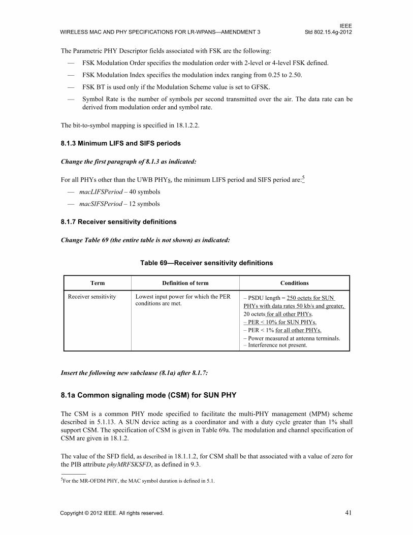
IEEEWIRELESS MAC AND PHY SPECIFICATIONS FOR LR-WPANS—AMENDMENT 3 Std 802.15.4g-2012
The Parametric PHY Descriptor fields associated with FSK are the following:
— FSK Modulation Order specifies the modulation order with 2-level or 4-level FSK defined.
— FSK Modulation Index specifies the modulation index ranging from 0.25 to 2.50.
— FSK BT is used only if the Modulation Scheme value is set to GFSK.
— Symbol Rate is the number of symbols per second transmitted over the air. The data rate can be derived from modulation order and symbol rate.
The bit-to-symbol mapping is specified in 18.1.2.2.
8.1.3 Minimum LIFS and SIFS periods
Change the first paragraph of 8.1.3 as indicated:
For all PHYs other than the UWB PHYs, the minimum LIFS period and SIFS period are:5
— macLIFSPeriod – 40 symbols
— macSIFSPeriod – 12 symbols
8.1.7 Receiver sensitivity definitions
Change Table 69 (the entire table is not shown) as indicated:
Insert the following new subclause (8.1a) after 8.1.7:
8.1a Common signaling mode (CSM) for SUN PHY
The CSM is a common PHY mode specified to facilitate the multi-PHY management (MPM) scheme described in 5.1.13. A SUN device acting as a coordinator and with a duty cycle greater than 1% shall support CSM. The specification of CSM is given in Table 69a. The modulation and channel specification of CSM are given in 18.1.2.
The value of the SFD field, as described in 18.1.1.2, for CSM shall be that associated with a value of zero for the PIB attribute phyMRFSKSFD, as defined in 9.3.
5For the MR-OFDM PHY, the MAC symbol duration is defined in 5.1.
Table 69—Receiver sensitivity definitions
Term Definition of term Conditions
Receiver sensitivity Lowest input power for which the PER conditions are met.
– PSDU length = 250 octets for SUN PHYs with data rates 50 kb/s and greater, 20 octets for all other PHYs.– PER < 10% for SUN PHYs.– PER < 1% for all other PHYs.– Power measured at antenna terminals.– Interference not present.
Copyright © 2012 IEEE. All rights reserved. 41
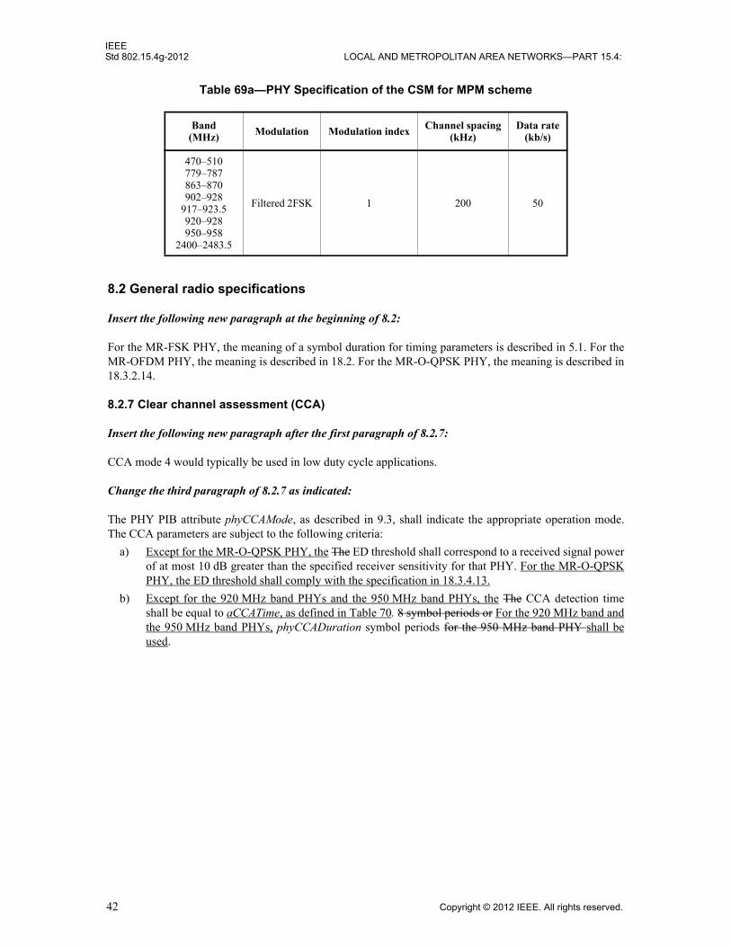
IEEEStd 802.15.4g-2012 LOCAL AND METROPOLITAN AREA NETWORKS—PART 15.4:
8.2 General radio specifications
Insert the following new paragraph at the beginning of 8.2:
For the MR-FSK PHY, the meaning of a symbol duration for timing parameters is described in 5.1. For the MR-OFDM PHY, the meaning is described in 18.2. For the MR-O-QPSK PHY, the meaning is described in 18.3.2.14.
8.2.7 Clear channel assessment (CCA)
Insert the following new paragraph after the first paragraph of 8.2.7:
CCA mode 4 would typically be used in low duty cycle applications.
Change the third paragraph of 8.2.7 as indicated:
The PHY PIB attribute phyCCAMode, as described in 9.3, shall indicate the appropriate operation mode. The CCA parameters are subject to the following criteria:
a) Except for the MR-O-QPSK PHY, the The ED threshold shall correspond to a received signal power of at most 10 dB greater than the specified receiver sensitivity for that PHY. For the MR-O-QPSK PHY, the ED threshold shall comply with the specification in 18.3.4.13.
b) Except for the 920 MHz band PHYs and the 950 MHz band PHYs, the The CCA detection time shall be equal to aCCATime, as defined in Table 70. 8 symbol periods or For the 920 MHz band and the 950 MHz band PHYs, phyCCADuration symbol periods for the 950 MHz band PHY shall be used.
Table 69a—PHY Specification of the CSM for MPM scheme
Band(MHz) Modulation Modulation index Channel spacing
(kHz)Data rate
(kb/s)
470–510779–787863–870902–928
917–923.5920–928950–958
2400–2483.5
Filtered 2FSK 1 200 50
42 Copyright © 2012 IEEE. All rights reserved.

IEEEWIRELESS MAC AND PHY SPECIFICATIONS FOR LR-WPANS—AMENDMENT 3 Std 802.15.4g-2012
9. PHY services
9.2 PHY constants
Change Table 70 as indicated:
9.3 PHY PIB attributes
The first paragraph of 9.3 is reproduced here to assist the reader in understanding the notation used in Table 71. No changes are made to this paragraph.
The PHY PIB comprises the attributes required to manage the PHY of a device. The attributes contained in the PHY PIB are presented in Table 71. Attributes marked with a dagger (†) are read-only attributes (i.e., attribute can only be set by the PHY), which can be read by the next higher layer using the MLME-GET.request primitive. All other attributes can be read or written by the next higher layer using the MLME-GET.request or MLME-SET.request primitives, respectively.
Table 70—PHY constants
Constant Description Value
aMaxPHYPacketSize The maximum PSDU size (in octets) the PHY shall be able to receive.
2047 for SUN PHYs
127 for all other PHYs
aTurnaroundTime RX-to-TX or TX-to-RX turnaround time (in sym-bol periods), as defined in 8.2.1 and 8.2.2.
For the SUN PHYs, the value is 1 ms expressed in symbol periods, rounded up to the next integer number of symbol periods using the ceiling() function.a The value is 12 for all other PHYs.
aThe function ceiling() returns the smallest integer value greater than or equal to its argument value.
aCCATime The time required to perform CCA detection. For the SUN PHYs other than MR-O-QPSK, the duration of 8 symbol periods, as defined in 5.1. For the MR-O-QPSK PHY, this value is defined in Table 188.For all other PHYs, the duration of 8 symbol periods.
aMRFSKPHRLength The length of the PHR, in octets, for the MR-FSK PHY.
2
aMRFSKSFDLength The length of the SFD, in octets, for the MR-FSK PHY. 2
aMROQPSKPHRLength The length of the PHR, in octets, for the MR-O-QPSK PHY. 3
aMROQPSKSFDLength The length of the SFD, in octets, for the MR-O-QPSK PHY.
2
Copyright © 2012 IEEE. All rights reserved. 43
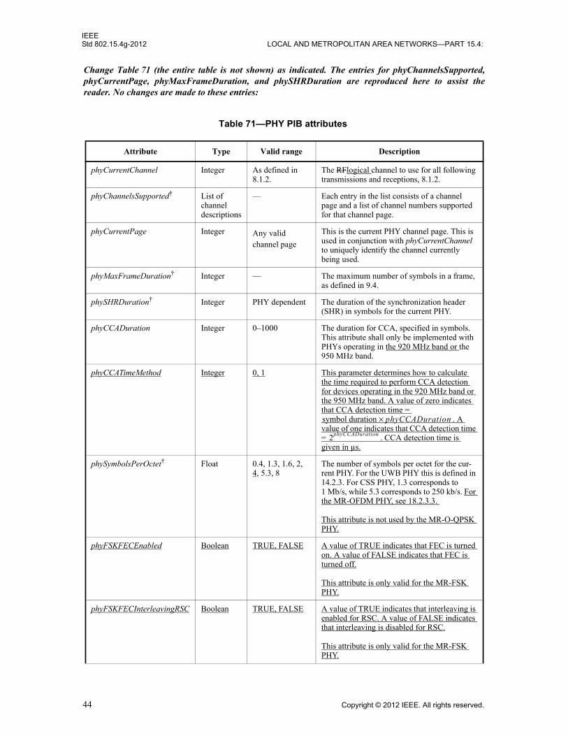
IEEEStd 802.15.4g-2012 LOCAL AND METROPOLITAN AREA NETWORKS—PART 15.4:
Change Table 71 (the entire table is not shown) as indicated. The entries for phyChannelsSupported, phyCurrentPage, phyMaxFrameDuration, and phySHRDuration are reproduced here to assist the reader. No changes are made to these entries:
Table 71—PHY PIB attributes
Attribute Type Valid range Description
phyCurrentChannel Integer As defined in 8.1.2.
The RFlogical channel to use for all following transmissions and receptions, 8.1.2.
phyChannelsSupported† List of channel descriptions
— Each entry in the list consists of a channel page and a list of channel numbers supported for that channel page.
phyCurrentPage Integer Any valid channel page
This is the current PHY channel page. This is used in conjunction with phyCurrentChannel to uniquely identify the channel currently being used.
phyMaxFrameDuration† Integer — The maximum number of symbols in a frame, as defined in 9.4.
phySHRDuration† Integer PHY dependent The duration of the synchronization header (SHR) in symbols for the current PHY.
phyCCADuration Integer 0–1000 The duration for CCA, specified in symbols.This attribute shall only be implemented with PHYs operating in the 920 MHz band or the 950 MHz band.
phyCCATimeMethod Integer 0, 1 This parameter determines how to calculate the time required to perform CCA detection for devices operating in the 920 MHz band or the 950 MHz band. A value of zero indicates that CCA detection time =
. A value of one indicates that CCA detection time = . CCA detection time is given in µs.
phySymbolsPerOctet† Float 0.4, 1.3, 1.6, 2, 4, 5.3, 8
The number of symbols per octet for the cur-rent PHY. For the UWB PHY this is defined in 14.2.3. For CSS PHY, 1.3 corresponds to 1 Mb/s, while 5.3 corresponds to 250 kb/s. For the MR-OFDM PHY, see 18.2.3.3.
This attribute is not used by the MR-O-QPSK PHY.
phyFSKFECEnabled Boolean TRUE, FALSE A value of TRUE indicates that FEC is turned on. A value of FALSE indicates that FEC is turned off.
This attribute is only valid for the MR-FSK PHY.
phyFSKFECInterleavingRSC Boolean TRUE, FALSE A value of TRUE indicates that interleaving is enabled for RSC. A value of FALSE indicates that interleaving is disabled for RSC.
This attribute is only valid for the MR-FSK PHY.
symbol duration phyCCADuration×
2phyCCADuration
44 Copyright © 2012 IEEE. All rights reserved.
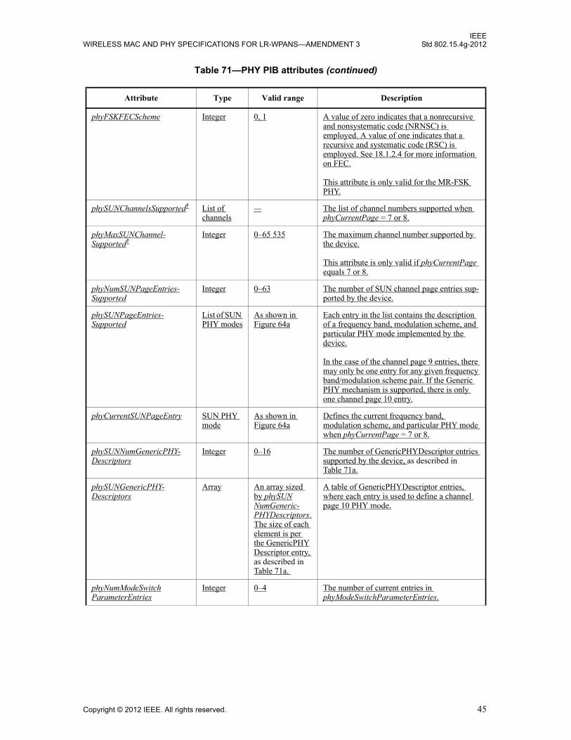
IEEEWIRELESS MAC AND PHY SPECIFICATIONS FOR LR-WPANS—AMENDMENT 3 Std 802.15.4g-2012
phyFSKFECScheme Integer 0, 1 A value of zero indicates that a nonrecursive and nonsystematic code (NRNSC) is employed. A value of one indicates that a recursive and systematic code (RSC) is employed. See 18.1.2.4 for more information on FEC.
This attribute is only valid for the MR-FSK PHY.
phySUNChannelsSupported† List of channels
— The list of channel numbers supported when phyCurrentPage = 7 or 8.
phyMaxSUNChannel-Supported†
Integer 0–65 535 The maximum channel number supported by the device.
This attribute is only valid if phyCurrentPage equals 7 or 8.
phyNumSUNPageEntries-Supported
Integer 0–63 The number of SUN channel page entries sup-ported by the device.
phySUNPageEntries-Supported
List of SUN PHY modes
As shown in Figure 64a
Each entry in the list contains the description of a frequency band, modulation scheme, and particular PHY mode implemented by the device.
In the case of the channel page 9 entries, there may only be one entry for any given frequency band/modulation scheme pair. If the Generic PHY mechanism is supported, there is only one channel page 10 entry.
phyCurrentSUNPageEntry SUN PHY mode
As shown in Figure 64a
Defines the current frequency band, modulation scheme, and particular PHY mode when phyCurrentPage = 7 or 8.
phySUNNumGenericPHY-Descriptors
Integer 0–16 The number of GenericPHYDescriptor entries supported by the device, as described in Table 71a.
phySUNGenericPHY-Descriptors
Array An array sized by phySUNNumGeneric-PHYDescriptors. The size of each element is per the GenericPHYDescriptor entry, as described in Table 71a.
A table of GenericPHYDescriptor entries, where each entry is used to define a channel page 10 PHY mode.
phyNumModeSwitchParameterEntries
Integer 0–4 The number of current entries in phyModeSwitchParameterEntries.
Table 71—PHY PIB attributes (continued)
Attribute Type Valid range Description
Copyright © 2012 IEEE. All rights reserved. 45

IEEEStd 802.15.4g-2012 LOCAL AND METROPOLITAN AREA NETWORKS—PART 15.4:
phyModeSwitchParameterEntries
Array RxS array of ModeSwitchDescriptor entries. R ranges from 1 to 4. S contains the elements of ModeSwitchDescriptor entry in Table 71b.
An array of up to four rows, where each row consists of a set of ModeSwitchDescriptor entries.
This attribute is only valid for the MR-FSK PHY.
phyFSKPreambleLength Integer 4–1000 The number of 1-octet patterns, as described in 18.1.1.1, in the preamble.
This attribute is only valid for the MR-FSK PHY.
phyMRFSKSFD Integer 0, 1 Determines which group of SFDs is used, as described in Table 131.
This attribute is only valid for the MR-FSK PHY.
phyFSKScramblePSDU Boolean TRUE or FALSE A value of FALSE indicates that data whitening of the PSDU is disabled. A value of TRUE indicates that data whitening of the PSDU is enabled.
This attribute is only valid for the MR-FSK PHY.
phyOFDMInterleaving Integer 0, 1 A value of zero indicates an interleaving depth of one symbol. A value of one indicates an interleaving depth of the number of symbols equal to the frequency domain spreading factor (SF).
This attribute is only valid for the MR-OFDM PHY.
phyPHRDuration Integer 3, 4, 6, 8, or 15 The duration of the PHR, in symbols, for the current PHY.If the phyOFDMInterleaving attribute is zero, this attribute has a value of three for OFDM Option 1 and a value of six for OFDM Options 2, 3, and 4. If the phyOFDMInterleaving attribute is one, this attribute has a value of four for OFDM Option 1, a value of eight for OFDM Option 2, and a value of six for OFDM Options 3 and 4. For the MR-O-QPSK PHY, this attribute has a value of fifteen.
This attribute is only valid for the MR-OFDM PHY and MR-O-QPSK PHY.
Table 71—PHY PIB attributes (continued)
Attribute Type Valid range Description
46 Copyright © 2012 IEEE. All rights reserved.

IEEEWIRELESS MAC AND PHY SPECIFICATIONS FOR LR-WPANS—AMENDMENT 3 Std 802.15.4g-2012
Insert the following new tables (Table 71a, Table 71b) after Table 71:
Table 71a—Elements of GenericPHYDescriptor
Name Type Valid range Description
GenericPHYID Integer 0–15 The identifier of the MR-FSK Generic PHY mode. This ID corresponds to a bit position (0–15) in the channel page 10 channel page definition, as defined in 8.1.2.10.2.
FirstChannelCenterFrequency Integer 1–2 485 000 000 Specifies the center frequency, in hertz, of the first channel in the list.
NumberOfChannels Integer 0–65 535 The number of channels defined for the particular PHY mode. The actual chan-nels supported by the device are defined by phySUNChannelsSupported.
ChannelSpacing Integer 1–4 000 000 The distance between adjacent channel center frequencies in hertz.
ModulationScheme Integer 0–3 The modulation scheme of the MR-FSK Generic PHY entry. This parameter can take one of the following values:
0 = FSK1 = GFSK2–3 = reserved
The remaining parameters in this table are determined based on the value of the ModulationScheme parameter.
FSKModulationOrder Integer 0–3 The modulation order if the value of the ModulationScheme parameter is 0 or 1. This parameter can take one of the following values:
0 = 2-level1 = 4-level2–3 = reserved
FSKModulationIndex Float 0.25–2.50(step size of 0.05)
The modulation index if the value of the ModulationScheme parameter is zero or one.
FSKBT Integer 0–3 The BT value if the value of the ModulationScheme parameter is one. This parameter can take one of the following values:
0 = BT is 0.51 = BT is 1.02–3 = reserved
SymbolRate Integer 1–2 000 000 The symbol rate in symbols per second.
Copyright © 2012 IEEE. All rights reserved. 47
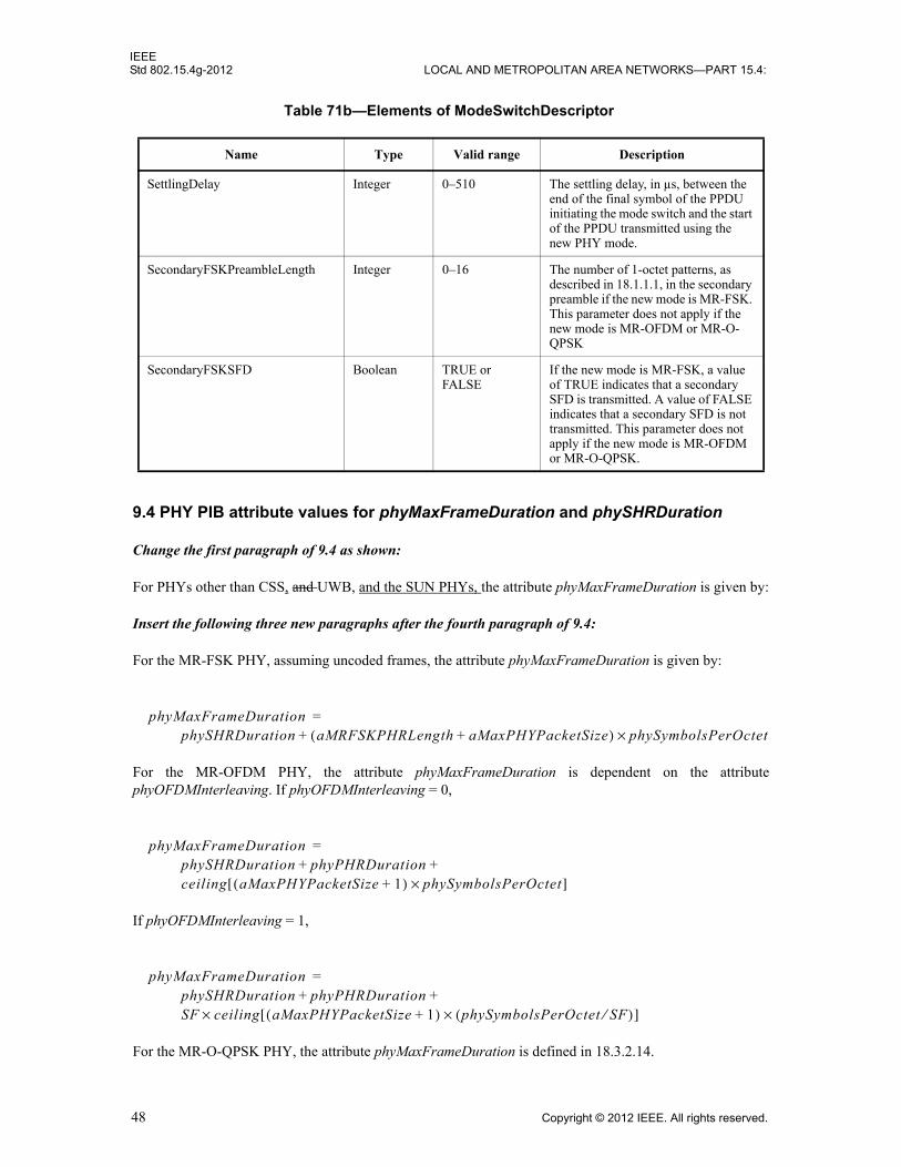
IEEEStd 802.15.4g-2012 LOCAL AND METROPOLITAN AREA NETWORKS—PART 15.4:
9.4 PHY PIB attribute values for phyMaxFrameDuration and phySHRDuration
Change the first paragraph of 9.4 as shown:
For PHYs other than CSS, and UWB, and the SUN PHYs, the attribute phyMaxFrameDuration is given by:
Insert the following three new paragraphs after the fourth paragraph of 9.4:
For the MR-FSK PHY, assuming uncoded frames, the attribute phyMaxFrameDuration is given by:
For the MR-OFDM PHY, the attribute phyMaxFrameDuration is dependent on the attributephyOFDMInterleaving. If phyOFDMInterleaving = 0,
If phyOFDMInterleaving = 1,
For the MR-O-QPSK PHY, the attribute phyMaxFrameDuration is defined in 18.3.2.14.
Table 71b—Elements of ModeSwitchDescriptor
Name Type Valid range Description
SettlingDelay Integer 0–510 The settling delay, in µs, between the end of the final symbol of the PPDU initiating the mode switch and the start of the PPDU transmitted using the new PHY mode.
SecondaryFSKPreambleLength Integer 0–16 The number of 1-octet patterns, as described in 18.1.1.1, in the secondary preamble if the new mode is MR-FSK. This parameter does not apply if the new mode is MR-OFDM or MR-O-QPSK
SecondaryFSKSFD Boolean TRUE or FALSE
If the new mode is MR-FSK, a value of TRUE indicates that a secondary SFD is transmitted. A value of FALSE indicates that a secondary SFD is not transmitted. This parameter does not apply if the new mode is MR-OFDM or MR-O-QPSK.
phyMaxFrameDuration =phySHRDuration aMRFSKPHRLength aMaxPHYPacketSize+( ) phySymbolsPerOctet×+
phyMaxFrameDuration =phySHRDuration phyPHRDuration+ +ceiling aMaxPHYPacketSize 1+( ) phySymbolsPerOctet×[ ]
phyMaxFrameDuration =phySHRDuration phyPHRDuration+ +SF ceiling aMaxPHYPacketSize 1+( ) phySymbolsPerOctet SF⁄( )×[ ]×
48 Copyright © 2012 IEEE. All rights reserved.

IEEEWIRELESS MAC AND PHY SPECIFICATIONS FOR LR-WPANS—AMENDMENT 3 Std 802.15.4g-2012
Change the last paragraph of 9.4 as indicated:
For PHYs other than the SUN PHYs, Tthe PHY PIB attribute phySHRDuration is given by:
Insert the following three new paragraphs after the last paragraph of 9.4:
For the MR-FSK PHY, the attribute phySHRDuration is given by:
For the MR-O-QPSK PHY, the attribute phySHRDuration is defined in 18.3.2.14.
For the MR-OFDM PHY, the attribute phySHRDuration has the value six.
phySHRDuration =phySymbolsPerOctet phyFSKPreambleLength aMRFSKSFDLength+( )×
Copyright © 2012 IEEE. All rights reserved. 49
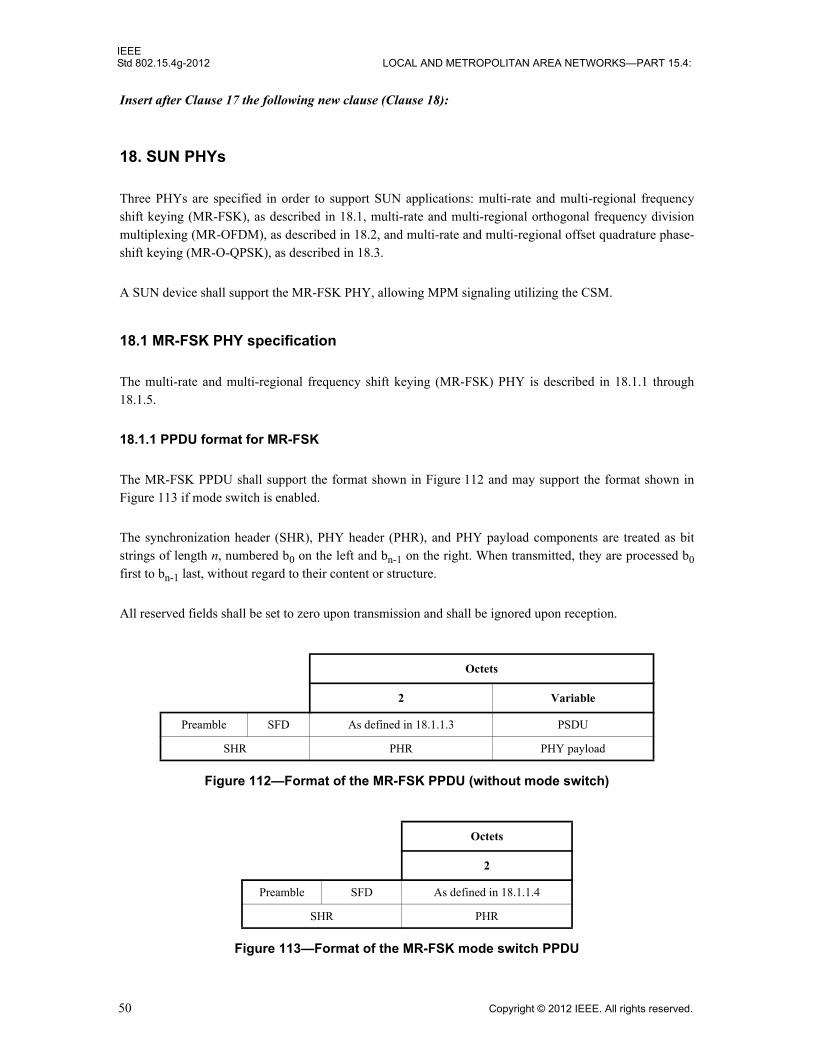
IEEEStd 802.15.4g-2012 LOCAL AND METROPOLITAN AREA NETWORKS—PART 15.4:
Insert after Clause 17 the following new clause (Clause 18):
18. SUN PHYs
Three PHYs are specified in order to support SUN applications: multi-rate and multi-regional frequencyshift keying (MR-FSK), as described in 18.1, multi-rate and multi-regional orthogonal frequency divisionmultiplexing (MR-OFDM), as described in 18.2, and multi-rate and multi-regional offset quadrature phase-shift keying (MR-O-QPSK), as described in 18.3.
A SUN device shall support the MR-FSK PHY, allowing MPM signaling utilizing the CSM.
18.1 MR-FSK PHY specification
The multi-rate and multi-regional frequency shift keying (MR-FSK) PHY is described in 18.1.1 through18.1.5.
18.1.1 PPDU format for MR-FSK
The MR-FSK PPDU shall support the format shown in Figure 112 and may support the format shown inFigure 113 if mode switch is enabled.
The synchronization header (SHR), PHY header (PHR), and PHY payload components are treated as bitstrings of length n, numbered b0 on the left and bn-1 on the right. When transmitted, they are processed b0first to bn-1 last, without regard to their content or structure.
All reserved fields shall be set to zero upon transmission and shall be ignored upon reception.
Octets
2 Variable
Preamble SFD As defined in 18.1.1.3 PSDU
SHR PHR PHY payload
Figure 112—Format of the MR-FSK PPDU (without mode switch)
Octets
2
Preamble SFD As defined in 18.1.1.4
SHR PHR
Figure 113—Format of the MR-FSK mode switch PPDU
50 Copyright © 2012 IEEE. All rights reserved.

IEEEWIRELESS MAC AND PHY SPECIFICATIONS FOR LR-WPANS—AMENDMENT 3 Std 802.15.4g-2012
18.1.1.1 Preamble field
The Preamble field shall contain phyFSKPreambleLength (as defined in 9.3) multiples of the 8-bit sequence“01010101” for filtered 2FSK. The Preamble field shall contain phyFSKPreambleLength multiples of the16-bit sequence “0111 0111 0111 0111” for filtered 4FSK.
18.1.1.2 SFD
The SFD for filtered 2FSK shall be a 2-octet sequence selected from the list of values shown in Table 131.The SFD for filtered 4FSK shall be a 4-octet sequence selected from the list of values shown in Table 132.Devices that do not support FEC shall support the SFD associated with uncoded (PHR + PSDU) and a valueof zero for the PIB attribute phyMRFSKSFD, as defined in 9.3; these devices may also support the SFDassociated with uncoded (PHR + PSDU) and a value of one for the PIB attribute phyMRFSKSFD. Devicesthat support FEC shall support both SFDs associated with a value of zero for the PIB attributephyMRFSKSFD; these devices may additionally support both SFDs associated with a value of one for thePIB attribute phyMRFSKSFD.
The SFD is transmitted starting from the leftmost bit (i.e., starting with b0).
18.1.1.3 PHR (without mode switch)
The format of the PHR is shown in Figure 114. All multi-bit fields are unsigned integers and shall beprocessed MSB first.
The Mode Switch field (MS) shall be set to zero, indicating that the entire packet shall be transmitted at asingle data rate and using a single modulation scheme.
The FCS Type field (FCS) indicates the length of the FCS field described in 5.2.1.9 that is included in theMPDU. Table 133 shows the relationship between the contents of the FCS Type field and the length of thetransmitted FCS.
Table 131—MR-FSK PHY SFD values for filtered 2FSK
SFD value for coded (PHR + PSDU)
(b0–b15)
SFD value for uncoded (PHR + PSDU)
(b0–b15)
phyMRFSKSFD = 0 0110 1111 0100 1110 1001 0000 0100 1110
phyMRFSKSFD = 1 0110 0011 0010 1101 0111 1010 0000 1110
Table 132—MR-FSK PHY SFD values for filtered 4FSK
SFD value for coded (PHR + PSDU)
(b0–b31)
SFD value for uncoded (PHR + PSDU)
(b0–b31)
phyMRFSKSFD = 0 0111 1101 1111 1111 0111 0101 1111 1101 1101 0111 0101 0101 0111 0101 1111 1101
phyMRFSKSFD = 1 0111 1101 0101 1111 0101 1101 1111 0111 0111 1111 1101 1101 0101 0101 1111 1101
Copyright © 2012 IEEE. All rights reserved. 51
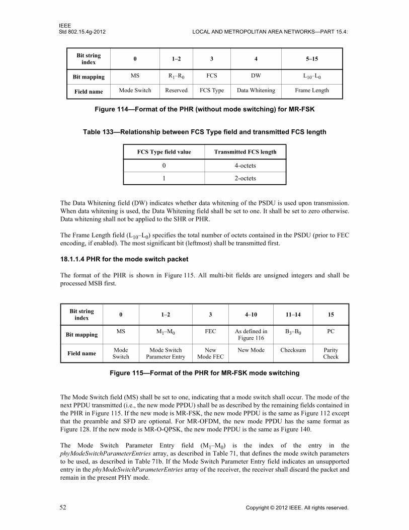
IEEEStd 802.15.4g-2012 LOCAL AND METROPOLITAN AREA NETWORKS—PART 15.4:
The Data Whitening field (DW) indicates whether data whitening of the PSDU is used upon transmission.When data whitening is used, the Data Whitening field shall be set to one. It shall be set to zero otherwise.Data whitening shall not be applied to the SHR or PHR.
The Frame Length field (L10–L0) specifies the total number of octets contained in the PSDU (prior to FECencoding, if enabled). The most significant bit (leftmost) shall be transmitted first.
18.1.1.4 PHR for the mode switch packet
The format of the PHR is shown in Figure 115. All multi-bit fields are unsigned integers and shall beprocessed MSB first.
The Mode Switch field (MS) shall be set to one, indicating that a mode switch shall occur. The mode of thenext PPDU transmitted (i.e., the new mode PPDU) shall be as described by the remaining fields contained inthe PHR in Figure 115. If the new mode is MR-FSK, the new mode PPDU is the same as Figure 112 exceptthat the preamble and SFD are optional. For MR-OFDM, the new mode PPDU has the same format asFigure 128. If the new mode is MR-O-QPSK, the new mode PPDU is the same as Figure 140.
The Mode Switch Parameter Entry field (M1–M0) is the index of the entry in thephyModeSwitchParameterEntries array, as described in Table 71, that defines the mode switch parametersto be used, as described in Table 71b. If the Mode Switch Parameter Entry field indicates an unsupportedentry in the phyModeSwitchParameterEntries array of the receiver, the receiver shall discard the packet andremain in the present PHY mode.
Bit string index
0 1–2 3 4 5–15
Bit mapping MS R1–R0 FCS DW L10–L0
Field name Mode Switch Reserved FCS Type Data Whitening Frame Length
Figure 114—Format of the PHR (without mode switching) for MR-FSK
Table 133—Relationship between FCS Type field and transmitted FCS length
FCS Type field value Transmitted FCS length
0 4-octets
1 2-octets
Bit string index
0 1–2 3 4–10 11–14 15
Bit mapping MS M1–M0 FEC As defined in Figure 116
B3–B0 PC
Field name Mode Switch
Mode Switch Parameter Entry
New Mode FEC
New Mode Checksum Parity Check
Figure 115—Format of the PHR for MR-FSK mode switching
52 Copyright © 2012 IEEE. All rights reserved.

IEEEWIRELESS MAC AND PHY SPECIFICATIONS FOR LR-WPANS—AMENDMENT 3 Std 802.15.4g-2012
The New Mode FEC field (FEC) specifies whether the packet following the mode switch PPDU istransmitted using FEC. A value of zero indicates that the new mode packet is transmitted without FEC, anda value of one indicates that it is transmitted with FEC. If the new mode packet has an SFD and, therefore,packet coding information, as described in 18.1.2.4, the SFD shall override the value of the New Mode FECfield.
The New Mode field is formatted as shown in Figure 116. The format of the new mode PPDU is determinedby the New Mode field. The Page field (PAGE) shall be set to zero to indicate channel page nine or set toone to indicate channel page ten. The Modulation Scheme field (MOD1–MOD0) indicates the modulationscheme, as described in Table 68g, when phyCurrentChannel (as defined in 9.3) equals seven; whenphyCurrentChannel equals eight, the Modulation Scheme field shall be set to zero upon transmission andignored upon reception. The Mode field (MD3–MD0) specifies the new mode of operation. When the Pagefield is zero (channel page nine), the interpretation of the Mode field (MD3-MD0) is based on themodulation scheme:
— If the modulation scheme is filtered FSK, the integer value of MD3–MD0 is the integer value of thespecific FSK mode in the FSK modes supported bitmap, as described in Figure 64a.
— If the modulation scheme is not filtered FSK, the bits (MD3–MD0) shall be set to zero upontransmission and ignored upon reception. The corresponding data rates are specified in the PHR ofthe new mode PPDU.
When the Page field is one (channel page ten), the Mode field selects one element (0–15) in thephySUNGenericPHYDescriptors (as defined in 9.3), and the new PHY mode is defined by the MR-FSKGeneric PHY mechanism.
The Checksum field (B3–B0) is the checksum for the BCH(15,11) code. The generator polynomial for theBose Chaudhuri Hocquenghem (BCH) code is as follows:
.
The Parity Check (PC) field provides error detection for the mode switch PPDU. Its value is calculated fromthe following equation:
where ⊕ is modulo-2 addition (addition over GF(2)). The combination of the BCH(15,11) code and oneparity bit allows for the achievement of single error correction and double error detection over the 11 bits ofinformation in the mode switch PPDU.
If the receiving device receives a PHR with the MS field set to one, it first performs the BCH calculationover the first 11 bits of the PHR. If the resulting checksum is valid, and the MS field is still set to one aftererror correction, a parity check using the PC field is performed. If the result of the parity check is valid, the
Bit string index 4 5–6 7–10
Bit mapping PAGE MOD1–MOD0 MD3–MD0
Field name Page Modulation Scheme Mode
Figure 116—Format of the New Mode field
G x( ) 1 x x4+ +=
PC MS M0 M1 FEC PAGE MOD0 MOD1 MD0 MD1 MD2 MD3⊕ ⊕ ⊕ ⊕ ⊕ ⊕ ⊕ ⊕ ⊕ ⊕=
Copyright © 2012 IEEE. All rights reserved. 53
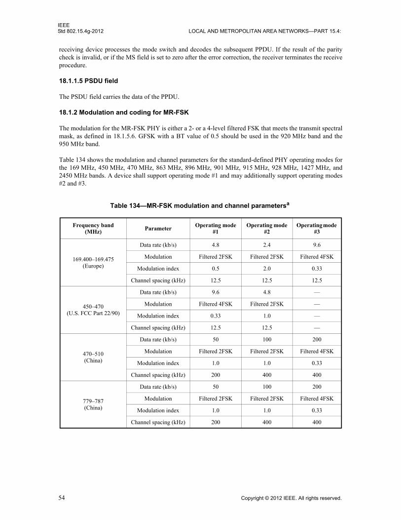
IEEEStd 802.15.4g-2012 LOCAL AND METROPOLITAN AREA NETWORKS—PART 15.4:
receiving device processes the mode switch and decodes the subsequent PPDU. If the result of the paritycheck is invalid, or if the MS field is set to zero after the error correction, the receiver terminates the receiveprocedure.
18.1.1.5 PSDU field
The PSDU field carries the data of the PPDU.
18.1.2 Modulation and coding for MR-FSK
The modulation for the MR-FSK PHY is either a 2- or a 4-level filtered FSK that meets the transmit spectralmask, as defined in 18.1.5.6. GFSK with a BT value of 0.5 should be used in the 920 MHz band and the950 MHz band.
Table 134 shows the modulation and channel parameters for the standard-defined PHY operating modes forthe 169 MHz, 450 MHz, 470 MHz, 863 MHz, 896 MHz, 901 MHz, 915 MHz, 928 MHz, 1427 MHz, and2450 MHz bands. A device shall support operating mode #1 and may additionally support operating modes#2 and #3.
Table 134—MR-FSK modulation and channel parametersa
Frequency band (MHz) Parameter Operating mode
#1Operating mode
#2Operating mode
#3
169.400–169.475(Europe)
Data rate (kb/s) 4.8 2.4 9.6
Modulation Filtered 2FSK Filtered 2FSK Filtered 4FSK
Modulation index 0.5 2.0 0.33
Channel spacing (kHz) 12.5 12.5 12.5
450–470(U.S. FCC Part 22/90)
Data rate (kb/s) 9.6 4.8 —
Modulation Filtered 4FSK Filtered 2FSK —
Modulation index 0.33 1.0 —
Channel spacing (kHz) 12.5 12.5 —
470–510 (China)
Data rate (kb/s) 50 100 200
Modulation Filtered 2FSK Filtered 2FSK Filtered 4FSK
Modulation index 1.0 1.0 0.33
Channel spacing (kHz) 200 400 400
779–787 (China)
Data rate (kb/s) 50 100 200
Modulation Filtered 2FSK Filtered 2FSK Filtered 4FSK
Modulation index 1.0 1.0 0.33
Channel spacing (kHz) 200 400 400
54 Copyright © 2012 IEEE. All rights reserved.

IEEEWIRELESS MAC AND PHY SPECIFICATIONS FOR LR-WPANS—AMENDMENT 3 Std 802.15.4g-2012
863–870 (Europe)
Data rate (kb/s) 50 100 200
Modulation Filtered 2FSK Filtered 2FSK Filtered 4FSK
Modulation index 1.0 1.0 0.33
Channel spacing (kHz) 200 400 400
896–901(U.S. FCC Part 90)
Data rate (kb/s) 10 20 40
Modulation Filtered 2FSK Filtered 2FSK Filtered 2FSK
Modulation index 0.5 0.5 0.5
Channel spacing (kHz) 12.5 12.5 12.5
901–902(U.S. FCC Part 24)
Data rate (kb/s) 10 20 40
Modulation Filtered 2FSK Filtered 2FSK Filtered 2FSK
Modulation index 0.5 0.5 0.5
Channel spacing (kHz) 12.5 12.5 12.5
902–928 (U.S. ISM)
Data rate (kb/s) 50 150 200
Modulation Filtered 2FSK Filtered 2FSK Filtered 2FSK
Modulation index 1.0 0.5 0.5
Channel spacing (kHz) 200 400 400
917–923.5(Korea)
Data rate (kb/s) 50 150 200
Modulation Filtered 2FSK Filtered 2FSK Filtered 2FSK
Modulation index 1.0 0.5 0.5
Channel spacing (kHz) 200 400 400
928–960b
(U.S. FCC Part 22/24/90/101)
Data rate (kb/s) 10 20 40
Modulation Filtered 2FSK Filtered 2FSK Filtered 2FSK
Modulation index 0.5 0.5 0.5
Channel spacing (kHz) 25 25 25
1427–1518b
(U.S. FCC Part 90)/(Canada SRSP 301.4)
Data rate (kb/s) 10 20 40
Modulation Filtered 2FSK Filtered 2FSK Filtered 2FSK
Modulation index 0.5 0.5 0.5
Channel spacing (kHz) 25 25 25
2400–2483.5 (Worldwide)
Data rate (kb/s) 50 150 200
Modulation Filtered 2FSK Filtered 2FSK Filtered 2FSK
Modulation index 1.0 0.5 0.5
Channel spacing (kHz) 200 400 400
aData rates shown are over-the-air data rates (the data rate transmitted over the air regardless of whether the FEC is enabled).
Table 134—MR-FSK modulation and channel parametersa (continued)
Frequency band (MHz) Parameter Operating mode
#1Operating mode
#2Operating mode
#3
Copyright © 2012 IEEE. All rights reserved. 55
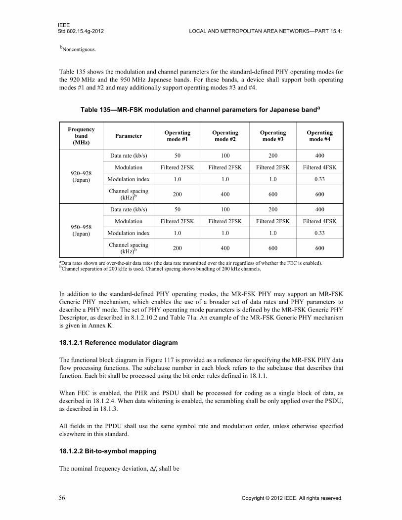
IEEEStd 802.15.4g-2012 LOCAL AND METROPOLITAN AREA NETWORKS—PART 15.4:
Table 135 shows the modulation and channel parameters for the standard-defined PHY operating modes forthe 920 MHz and the 950 MHz Japanese bands. For these bands, a device shall support both operatingmodes #1 and #2 and may additionally support operating modes #3 and #4.
In addition to the standard-defined PHY operating modes, the MR-FSK PHY may support an MR-FSKGeneric PHY mechanism, which enables the use of a broader set of data rates and PHY parameters todescribe a PHY mode. The set of PHY operating mode parameters is defined by the MR-FSK Generic PHYDescriptor, as described in 8.1.2.10.2 and Table 71a. An example of the MR-FSK Generic PHY mechanismis given in Annex K.
18.1.2.1 Reference modulator diagram
The functional block diagram in Figure 117 is provided as a reference for specifying the MR-FSK PHY dataflow processing functions. The subclause number in each block refers to the subclause that describes thatfunction. Each bit shall be processed using the bit order rules defined in 18.1.1.
When FEC is enabled, the PHR and PSDU shall be processed for coding as a single block of data, asdescribed in 18.1.2.4. When data whitening is enabled, the scrambling shall be only applied over the PSDU,as described in 18.1.3.
All fields in the PPDU shall use the same symbol rate and modulation order, unless otherwise specifiedelsewhere in this standard.
18.1.2.2 Bit-to-symbol mapping
The nominal frequency deviation, Δf, shall be
bNoncontiguous.
Table 135—MR-FSK modulation and channel parameters for Japanese banda
aData rates shown are over-the-air data rates (the data rate transmitted over the air regardless of whether the FEC is enabled).
Frequency band
(MHz)Parameter Operating
mode #1Operating mode #2
Operating mode #3
Operating mode #4
920–928(Japan)
Data rate (kb/s) 50 100 200 400
Modulation Filtered 2FSK Filtered 2FSK Filtered 2FSK Filtered 4FSK
Modulation index 1.0 1.0 1.0 0.33
Channel spacing (kHz)b
bChannel separation of 200 kHz is used. Channel spacing shows bundling of 200 kHz channels.
200 400 600 600
950–958(Japan)
Data rate (kb/s) 50 100 200 400
Modulation Filtered 2FSK Filtered 2FSK Filtered 2FSK Filtered 4FSK
Modulation index 1.0 1.0 1.0 0.33
Channel spacing (kHz)b 200 400 600 600
56 Copyright © 2012 IEEE. All rights reserved.

IEEEWIRELESS MAC AND PHY SPECIFICATIONS FOR LR-WPANS—AMENDMENT 3 Std 802.15.4g-2012
The symbol encoding for both filtered 2-level and 4-level FSK modulation is shown in Table 136, where thefrequency deviation, fdev, is equal to Δf for filtered 2FSK and is equal to for filtered 4FSK. Forfiltered 4FSK modulation, two bits shall be mapped to four frequency deviation levels for the PHR andPSDU. The SHR shall be encoded in the lowest (–fdev) and the highest (+fdev) frequency deviations. Thesymbol rate shall be the same for the entire PPDU.
18.1.2.3 Modulation quality
Modulation quality shall be measured by observing the frequency deviation tolerance and the zero crossingtolerance of the eye diagram caused by a PN9 sequence of length 511 bits.
18.1.2.3.1 Frequency deviation tolerance
Modulation frequency tolerance is measured as a percentage of the frequency deviation, fdev, dictated by themodulation index. In the case of filtered 2FSK, the measured frequency deviation, f, at Ts / 2 shall beconstrained to the range 70% fdev < |f| < 130% fdev, as shown in Figure 118, where Ts is the symbol time. Inthe case of filtered 4FSK, the measured frequency deviation, f, at Ts / 2 shall be constrained to the range 8%fdev < |f| < 58% fdev for the inner levels and 75% fdev < |f| < 125% fdev for the outer levels, as shown inFigure 119.
Figure 117—MR-FSK FEC, data whitening, and modulator functions
Forward error correction
coding block(16.1.2.4)
Binary {PSDU, PHR}
Controlled by phyFSKFEC
Co
nca
ten
ator
Data whitening
block(16.1.3)
Controlled by phyScramblePSDU
PHR
PSDU
SHR generation block
(16.1.1.2)
Bit-to-symbol mapping block
(16.1.2.2)
Filtered FSK modulation block
(16.1.2)
Modulated signalRF
symbol rate modulation index×2
----------------------------------------------------------------------------
3 Δf×
Copyright © 2012 IEEE. All rights reserved. 57
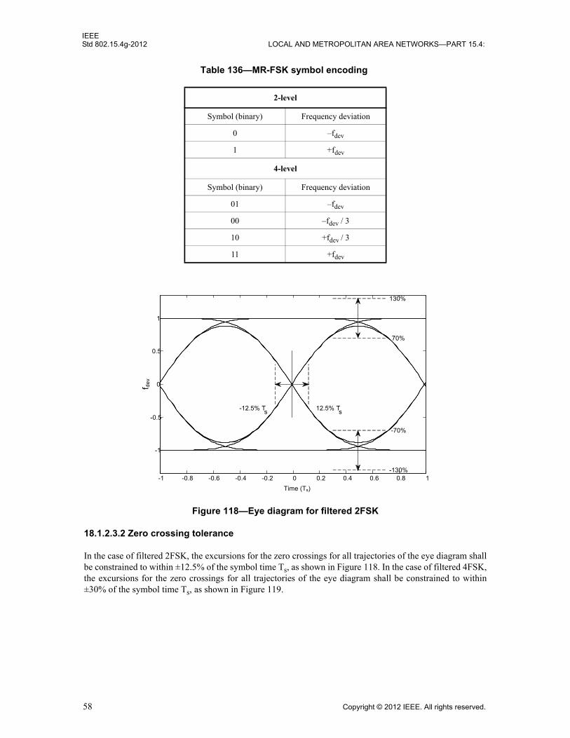
IEEEStd 802.15.4g-2012 LOCAL AND METROPOLITAN AREA NETWORKS—PART 15.4:
Figure 118—Eye diagram for filtered 2FSK
18.1.2.3.2 Zero crossing tolerance
In the case of filtered 2FSK, the excursions for the zero crossings for all trajectories of the eye diagram shallbe constrained to within ±12.5% of the symbol time Ts, as shown in Figure 118. In the case of filtered 4FSK,the excursions for the zero crossings for all trajectories of the eye diagram shall be constrained to within±30% of the symbol time Ts, as shown in Figure 119.
Table 136—MR-FSK symbol encoding
2-level
Symbol (binary) Frequency deviation
0 –fdev
1 +fdev
4-level
Symbol (binary) Frequency deviation
01 –fdev
00 –fdev / 3
10 +fdev / 3
11 +fdev
-1 -0.8 -0.6 -0.4 -0.2 0 0.2 0.4 0.6 0.8 1
-1
-0.5
0
0.5
1
Time (Ts)
70%
130%
-70%
-130%
12.5% Ts
-12.5% Ts
f dev
58 Copyright © 2012 IEEE. All rights reserved.

IEEEWIRELESS MAC AND PHY SPECIFICATIONS FOR LR-WPANS—AMENDMENT 3 Std 802.15.4g-2012
Figure 119—Eye diagram for filtered 4FSK
18.1.2.4 Forward error correction (FEC)
FEC is optional. If the SFD indicates that FEC is used, as described in Table 131, then the FEC is applied tothe PHR and PSDU as a single block of data.
Two types of FEC may be applied: a recursive and systematic code (RSC) or a nonrecursive andnonsystematic code (NRNSC). The use of RSC or NRNSC coding shall be controlled by the PIB attributephyFSKFECScheme, as defined in 9.3.
When the SFD value indicates a coded packet, FEC shall be employed on the PHR and PSDU bits, applyingeither a 1/2-rate systematic or nonsystematic convolution coding with constraint length K = 4, and using thefollowing two generator polynomials:
The total number of bits to be encoded, N, is obtained by summing up the size of the PHR (LPHR), the lengthof the PSDU (LPSDU is equal to the content of the Frame Length field in Figure 114), the number of tail bits(LTAIL), and the number of padding bits (LPAD). N shall be computed as follows:
(5)
Note that LPSDU is zero in the case of a mode switch packet.
-1 -0.8 -0.6 -0.4 -0.2 0 0.2 0.4 0.6 0.8 1
-1
-0.5
0
0.5
1
Time (Ts)
125%
75%
-125%
-75%
58%
8%
-58%
-8%
30% Ts-30% Ts
f dev
G0 x( ) 1 x x2 x3+ + +=
G1 x( ) 1 x2 x3+ +=
N LPHR LPSDU LTAIL LPAD+ + +=
Copyright © 2012 IEEE. All rights reserved. 59

IEEEStd 802.15.4g-2012 LOCAL AND METROPOLITAN AREA NETWORKS—PART 15.4:
Immediately after encoding the PHR and PSDU, a termination sequence with length LTAIL = 3 bits shall beinserted into the encoder, as shown in Figure 120. The tail bits are required to return the encoder to the zerostate.
The value of the tail bits are dependent on the coding scheme and shall be set as shown in Table 137.
When interleaving is used in conjunction with convolutional coding, a padding sequence of LPAD bits shallbe further inserted into the encoder immediately after the tail bits. The padding bits are required to fill up thelast interleaver buffer completely, as described in 18.1.2.5. LPAD shall be computed as follows:
is odd
is even
Padding bit patterns should not contain a long series of ‘1’s or ‘0’s. Figure 121 and Figure 122 illustrateexamples of such patterns.The RSC encoder is shown in Figure 123, and the NRNSC encoder is shown inFigure 124.
PHR PSDUTail bits
(T0 T1 T2)
Figure 120—Data block extension with tail bits prior to coding
Table 137—Tail bit pattern for the RSC and NRNSC encoders
Memory state(M0–M2)
Tail bits
RSC(T0 T1 T2)
NRNSC(T0 T1 T2)
000 000 000
001 100 000
010 110 000
011 010 000
100 111 000
101 011 000
110 001 000
111 101 000
LPAD 5 when LPHR LPSDU+
8----------------------------------,=
LPAD 13 when LPHR LPSDU+
8----------------------------------,=
60 Copyright © 2012 IEEE. All rights reserved.

IEEEWIRELESS MAC AND PHY SPECIFICATIONS FOR LR-WPANS—AMENDMENT 3 Std 802.15.4g-2012
PHR PSDU Tail bits(T0 T1 T2)
5-bit padding pattern01011
Figure 121—An example of extension with padding bits prior to encoding, when is odd
PHR PSDU Tail bits(T0 T1 T2)
13-bit padding pattern0 1011 0000 1011
Figure 122—An example of extension with padding bits prior to encoding, when is even
Figure 123—The recursive and systematic code (RSC) encoder
0iu
1iu
T a il b it in s e rte r
b i-1 b i-2 b i-3
M 0
P a d b it in s e rte r
T i
In p u t b it b i
M 1 M 2
Figure 124—Non-recursive and non-systematic code (NRNSC) encoder
bi-1 bi-2 bi-3
Tail bits Ti inserter
Padding bits inserter
u1i
u0i
M0 M1 M2
Input bits: {bi}
LPHR LPSDU+( ) 8⁄
LPHR LPSDU+( ) 8⁄
Copyright © 2012 IEEE. All rights reserved. 61

IEEEStd 802.15.4g-2012 LOCAL AND METROPOLITAN AREA NETWORKS—PART 15.4:
For an input sequence of bits with length N, , the ith input bit shall be represented as bi and be fed into memory state M0, M1, and M2 in that order. The tail bits Ti and the pad bits shall be inserted once the encoding of PHR and PSDU is complete. The output sequence S also comprises N code-symbols.
Each code-symbol is denoted by , where s(i) is the ith outputcode-symbol due to the ith input bit and and indicate the first and second output bits of theconvolutional encoder, respectively. The code-symbol s(i) shall precede the code-symbol s(i + 1) and thecode bit shall precede the code bit .
For the RSC encoder, the first and the second output bits of the encoder shall be generated in the followingway:
where stands for modulo-2 addition.
For the NRNSC encoder, the first and the second output bits of the encoder shall be generated in thefollowing way:
where the “overline” indicates the complement of the modulo-2 addition.
18.1.2.5 Code-symbol interleaving
Interleaving of code-bits shall be employed in conjunction with NRNSC coding, in order to improverobustness against burst errors and to break correlation of consecutive bits. Interleaving may also beemployed with RSC coding. In the case of RSC coding, the use of the interleaver is controlled by the PIBattribute phyFSKFECInterleavingRSC, as defined in 9.3. No interleaving shall be employed if FEC is notenabled. The interleaver is defined by a permutation of code-symbols, where each permuted elementcontains exactly one code-symbol, i.e., a pair of two bits, as described in 18.1.2.4. The process ofinterleaving is illustrated in Figure 125.
B bi i 0 1 2 … N 1–, , , ,[ ]∈,{ }=
S s 0( ) s 1( ) s 2( ) … s N 1–( ), ,,{ , } u01 u0
0 … ui1 ui
0 ui 1+1 ui 1+
0 … uN 1–1 uN 1–
0, , , , , , , , ,{ }==
s i( ) ui1
ui0,{ } for all i, 0 … N 1–, ,= =
ui1
ui0
ui1
ui0
ui1 bi bi 1– bi 2– bi 3–⊕ ⊕( ) bi 2– bi 3–⊕ ⊕ ⊕=
ui0 bi=
⊕
ui1 bi bi 2– bi 3–⊕ ⊕=
ui0
bi bi 1– bi 2– bi 3–⊕ ⊕ ⊕=
62 Copyright © 2012 IEEE. All rights reserved.

IEEEWIRELESS MAC AND PHY SPECIFICATIONS FOR LR-WPANS—AMENDMENT 3 Std 802.15.4g-2012
The complete sequence of code-symbols S = {s(i)}, 0 ≤ i ≤ N–1, is passed to the interleaver as NBLOCKconsecutive subsequences A(p), where 0 ≤ p ≤ NBLOCK–1, , and N is a nonzero integermultiple of 16, as described in Equation (5). The subsequence A(0) shall be passed to the interleaver first intime, and the subsequence shall be passed to the interleaver last in time.
Each subsequence A(p) = {a(p)(j)} contains exactly 16 code-symbols and shall be derived according to thefollowing equation:
where
0 ≤ j ≤ 15
For each subsequence A(p) passed to the interleaver, the corresponding subsequence Q(p) = {q(p)(k)} exitingthe interleaver shall be computed as follows:
where
0 ≤ k ≤ 15
The function returns the largest integer value not greater than x.
The complete sequence of interleaved code-symbols is derived as .
Figure 125—The interleaving block
S T A R T
S T A R T
4 4
4
IN T E R L E A V E RS Q
W R IT E R E A D
4
NBLOCK N 16⁄=
ANBLOCK 1–( )
a p( ) j( ) s p 16 j+×( )=
q p( ) k( ) a p( ) t( )=
t 15 4 k mod 4( ) k4---–×–=
x floor x( )=
Q Q0( )
Q1( ) … Q
NBLOCK 1–( ), , ,{ }=
Copyright © 2012 IEEE. All rights reserved. 63

IEEEStd 802.15.4g-2012 LOCAL AND METROPOLITAN AREA NETWORKS—PART 15.4:
18.1.3 Data whitening for MR-FSK
Support for data whitening is optional.
When data whitening is enabled at the transmitter, the Data Whitening field of the PHR shall be set to one,as described in 18.1.1.3, and the whitened data shall be the exclusive or (XOR) of the PSDU with the PN9sequence, as described by the following equation:
whereEn is the whitened bit
Rn is the data bit being whitened
PN9n is the PN9 sequence bit
For each packet transmitted with data whitening enabled, R0 is the first bit of the PSDU and the index nincrements for subsequent bits of the PSDU.
For packets received with the Data Whitening field of the PHR set to one, the receiver decodes thescrambled data in the following way:
whereRn is the PSDU bit after de-whitening
REn is the PSDU bit at the output of the filtered FSK demodulator
The PN generator is defined by the schematic in Figure 126.
The seed in the PN9 generator shall be all ones: “111111111.” The PN9 generator shall be reinitialized to theseed after each packet (either transmit or receive).
The PN9 generator is clocked using the seed as the starting point and enabled after the first clock cycle. Forexample, the first 30 bits out of the PN9 generator, once it is enabled, would be as follows:
PN9n= 00, 01, 02, 03, 14, 15, 16, 17, 08, 19, 110, 111, 012, 013, 014, 015, 116, 017, 118, 119, 020, 021, 122, 123, 024,125, 126, 027, 128, 129.
En Rn PN9n⊕=
Rn REn PN9n⊕=
Figure 126—Schematic of the PN9 sequence generator
64 Copyright © 2012 IEEE. All rights reserved.

IEEEWIRELESS MAC AND PHY SPECIFICATIONS FOR LR-WPANS—AMENDMENT 3 Std 802.15.4g-2012
18.1.4 Mode switch mechanism for MR-FSK
The mode switch mechanism is optional.
The mode switch mechanism is enabled by setting the Mode Switch field to one. The MR-FSK mode switchPPDU is transmitted on phyCurrentChannel, as defined in 9.3, and the PPDU containing the PSDU istransmitted on the channel that corresponds to the same center frequency used for the MR-FSK mode switchPPDU. When an MR-FSK mode switch PPDU, as described in Figure 113, is received, a device thatsupports mode switching shall change its mode of operation to the new mode defined in the MR-FSK modeswitch PPDU, in order to receive the following packet.
When changing from the current operating mode to the new mode, a settling delay may exist. If themodulation scheme of the new mode is FSK, the settling delay shall be in the range of zero to 100 µs. If themodulation scheme of the new mode is not FSK, the settling delay shall be in the range of 200 µs to 500 µs.The settling delay value is part of a ModeSwitchDescriptor, as described in Table 71b. The value specifiedin the Mode Switch Parameter Entry field of the PHR, as described in Figure 115, is the index of the PIBattribute array phyModeSwitchParameterEntries, as defined in 9.3, which contains the elements of theModeSwitchDescriptor. How the Mode Switch Parameter Entry field maps to ModeSwitchDescriptor isexemplified in Table 138. For the mode switch operation of FSK->FSK, the symbol rate is changed. For themode switch operation of FSK->4FSK, the modulation order and/or the symbol rate is changed. The ModeSwitch Parameter Entry table may be defined by the next higher layer.
Transmission of the new mode PPDU shall start SettlingDelay from the end of the mode switch PPDU. TheSettlingDelay shall be the value indicated in the Mode Switch Parameter Entry field in the mode switchPPDU. The reception and rejection of the following packet follows the same mechanism described in5.1.6.2. When the new mode PPDU has been received, the receiver shall return to the mode specified byphyCurrentSUNPageEntry, as defined in 9.3, within a SIFS or LIFS period based on the symbol duration ofthe new mode PPDU, depending on the received frame length, as described in 5.1.1.3. If the transmission ofan ACK is requested by the transmitter, the ACK is transmitted using the PHY mode specified byphyCurrentSUNPageEntry.
The sequence of the MR-FSK mode switch PPDU, the optional settling delay, and the PPDU transmitted inthe new PHY mode is shown in Figure 127.
Devices employing the mode switch mechanism shall meet the MAC timing requirements of 5.1.1.1.1 and5.1.1.1.2, using the symbol duration of the PHY mode prior to the mode switch.
Table 138—An example of mapping between phyModeSwitchParameterEntries[ ] and ModeSwitchDescriptor
phyModeSwitchParameterEntries[ ]
Mode SwitchOperation
(Source mode -> Target mode)
ModeSwitchDescriptor
Settling Delay (µs)
SecondaryFSKPreamble Length
Secondary FSKSFD
0 FSK->FSK 20 0 FALSE
1 FSK->4FSK 40 0 FALSE
2 FSK->OFDM 160 n/a n/a
3 FSK->O-QPSK 80 n/a n/a
Copyright © 2012 IEEE. All rights reserved. 65
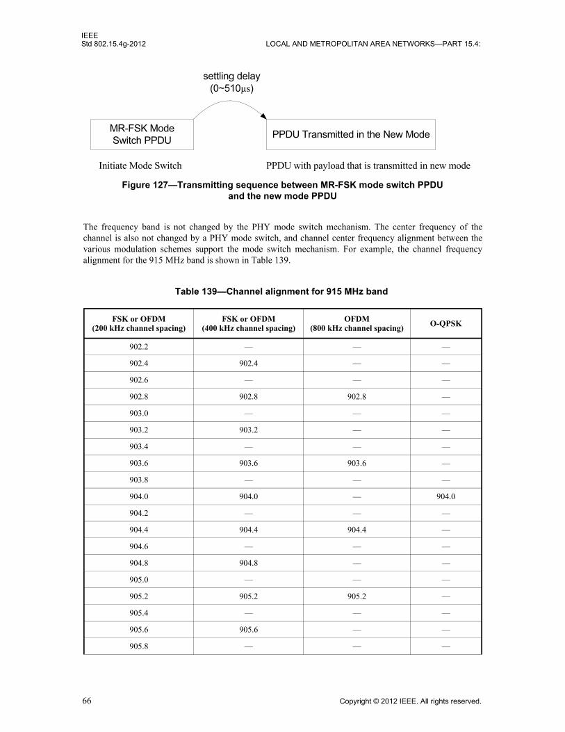
IEEEStd 802.15.4g-2012 LOCAL AND METROPOLITAN AREA NETWORKS—PART 15.4:
The frequency band is not changed by the PHY mode switch mechanism. The center frequency of thechannel is also not changed by a PHY mode switch, and channel center frequency alignment between thevarious modulation schemes support the mode switch mechanism. For example, the channel frequencyalignment for the 915 MHz band is shown in Table 139.
Table 139—Channel alignment for 915 MHz band
FSK or OFDM (200 kHz channel spacing)
FSK or OFDM(400 kHz channel spacing)
OFDM (800 kHz channel spacing) O-QPSK
902.2 — — —
902.4 902.4 — —
902.6 — — —
902.8 902.8 902.8 —
903.0 — — —
903.2 903.2 — —
903.4 — — —
903.6 903.6 903.6 —
903.8 — — —
904.0 904.0 — 904.0
904.2 — — —
904.4 904.4 904.4 —
904.6 — — —
904.8 904.8 — —
905.0 — — —
905.2 905.2 905.2 —
905.4 — — —
905.6 905.6 — —
905.8 — — —
Figure 127—Transmitting sequence between MR-FSK mode switch PPDU and the new mode PPDU
MR-FSK Mode Switch PPDU
PPDU Transmitted in the New Mode
settling delay(0~510µs)
Initiate Mode Switch PPDU with payload that is transmitted in new mode
66 Copyright © 2012 IEEE. All rights reserved.

IEEEWIRELESS MAC AND PHY SPECIFICATIONS FOR LR-WPANS—AMENDMENT 3 Std 802.15.4g-2012
18.1.5 MR-FSK PHY RF requirements
18.1.5.1 Operating frequency range
The MR-FSK PHY operates in the bands given in Table 134 and Table 135.
18.1.5.2 Regulatory compliance
It is the responsibility of the implementer to verify and ensure that the device is in compliance with allregulatory requirements in the geographic region where the device is deployed or sold. Conformance withthis standard does not guarantee compliance with the relevant regulatory requirements that may apply.
906.0 906.0 906.0 906.0
906.2 — — —
906.4 906.4 — —
906.6 — — —
906.8 906.8 906.8 —
907.0 — — —
907.2 907.2 — —
907.4 — — —
907.6 907.6 907.6 —
907.8 — — —
908.0 908.0 — 908.0
908.2 — — —
908.4 908.4 908.4 —
908.6 — — —
908.8 908.8 — —
909.0 — — —
909.2 909.2 909.2 —
909.4 — — —
909.6 909.6 — —
909.8 — — —
910.0 910.0 910.0 910.0
¦ ¦ ¦ ¦
etc. etc. etc. etc.
Table 139—Channel alignment for 915 MHz band (continued)
FSK or OFDM (200 kHz channel spacing)
FSK or OFDM(400 kHz channel spacing)
OFDM (800 kHz channel spacing) O-QPSK
Copyright © 2012 IEEE. All rights reserved. 67

IEEEStd 802.15.4g-2012 LOCAL AND METROPOLITAN AREA NETWORKS—PART 15.4:
18.1.5.3 Radio frequency tolerance
The single-sided clock frequency tolerance T at the transmitter, in ppm, shall be as follows:
for all combinations of R, h, and F and for each mode supported by the device, where R is the symbol rate in ksymbol/s h is the modulation indexF is the carrier frequency in MHzR0 is 50 ksymbol/s
h0 is 1
F0 is 915 MHz
T0 is 30 ppm for modes in all bands, except at 2450 MHz for which the value of T0 is 40 ppm
18.1.5.4 Channel switch time
Channel switch time shall be less than or equal to 500 µs. The channel switch time is defined as the timeelapsed when changing to a new channel, including any required settling time.
18.1.5.5 Transmitter symbol rate
The transmitter symbol rate tolerance shall be less than or equal to ±300 ppm. The peak transmitter symbolrate jitter shall be less than or equal to ±40 ppm. Transmitted packets shall have symbol rates within thespecified symbol rate tolerance, and all symbols within the packet shall be within the symbol rate tolerancerelative to the average symbol rate of all the symbols in the packet. The symbol rate jitter is measured as thestandard deviation of symbol edges from the nominal symbol edge position for the symbol rate used by thetransmitter.
18.1.5.6 Transmit spectral mask
The transmit spectral content is the ratio of the total transmitted out-of-channel power to the total transmittedin-channel power in a given integration bandwidth.
The integration bandwidth shall be equal to , where R is the symbol rate, expressed in units of hertz.
Out-of-channel power shall be measured at two offset frequencies relative to the carrier frequency. Theoffset frequencies M1 and M2 are defined as follows:
where h is the modulation index for 2-level modulation and three times the modulation index for 4-levelmodulation.
The transmit spectral content at M1 and M2 shall be less than –25 dB and –35 dB, respectively.
The modulated signal shall use a PN data pattern of 511 bits or longer.
T minT0 R h F0×××
R0 h0 F××------------------------------------- 50 ppm, ≤
1.5 R×
M1 1.5 R 1 h+( )××=
M2 3 R 1 h+( )××=
68 Copyright © 2012 IEEE. All rights reserved.

IEEEWIRELESS MAC AND PHY SPECIFICATIONS FOR LR-WPANS—AMENDMENT 3 Std 802.15.4g-2012
The spectrum analyzer settings for this measurement shall be as follows: the resolution bandwidth is 1 kHz,the video bandwidth is 1 kHz or greater, and the detector is RMS.
18.1.5.7 Receiver sensitivity
The MR-FSK receiver sensitivity shall be better than S, where S, for binary modulation, is defined asfollows:
dBm
where S0 is –91 without FEC and –97 with FEC
R0 is 50 kb/s
R is the bit rate in kb/s
See 8.1.7 for additional information on receiver sensitivity.
18.1.5.8 Receiver interference rejection
The adjacent designated channels are those on either side of the desired designated channel that are closestin frequency to the desired designated channel. The alternate designated channel is more than one removedfrom the desired designated channel in the operational frequency band.
The adjacent channel rejection shall be measured as follows: the desired signal shall be a compliant MR-FSK PHY signal, as defined in 18.1.2, of pseudo-random data at the center frequency of the desired channel.The desired signal is input to the receiver at a level 3 dB above the receiver sensitivity given in 18.1.5.7.
In either the adjacent or the alternate channel, an unmodulated carrier in the center of that channel is input atthe following level relative to the level of the desired signal:
— The adjacent channel rejection shall be greater than or equal to 10 dB.
— The alternate channel rejection shall be greater than or equal to 30 dB.
The test shall be performed for only one interfering signal at a time. The receiver shall meet the error ratecriteria defined in 8.1.7 under these conditions.
18.1.5.9 Tx-to-Rx turnaround time
The MR-FSK PHY shall meet the requirements for TX-to-RX turnaround time as defined in 8.2.1.
18.1.5.10 Rx-to-Tx turnaround time
The MR-FSK PHY shall meet the requirements for RX-to-TX turnaround time as defined in 8.2.2.
18.1.5.11 Transmit power
A transmitter shall be capable of transmitting at least –3 dBm. Devices should transmit lower power whenpossible in order to reduce interference to other devices and systems.
The maximum transmit power is limited by local regulatory bodies.
S S0 10RR0-----log+
=
Copyright © 2012 IEEE. All rights reserved. 69
IEEEStd 802.15.4g-2012 LOCAL AND METROPOLITAN AREA NETWORKS—PART 15.4:
18.1.5.12 Receiver maximum input level of desired signal
The MR-FSK PHY shall have a receiver maximum input level greater than or equal to –20 dBm using themeasurement defined in 8.2.4.
18.1.5.13 Receiver ED
The MR-FSK PHY shall provide the receiver ED measurement as described in 8.2.5.
18.1.5.14 Link quality indicator
The MR-FSK PHY shall provide the LQI measurement as described in 8.2.6.
18.1.5.15 Clear channel assessment (CCA)
The MR-FSK PHY shall use one of the CCA methods as described in 8.2.7.
18.2 MR-OFDM PHY specification
The multi-rate and multi-regional orthogonal frequency division multiplexing (MR-OFDM) PHY is RFband agnostic and supports data rates ranging from 50 kb/s to 800 kb/s. The subcarrier spacing is constantand is equal to 10416-2/3 Hz (or 31250/3 Hz).
The symbol rate is 8-1/3 ksymbol/s, which corresponds or 120 μs per symbol. Thissymbol includes a quarter-duration cyclic prefix (CP; 24 μs) and a base symbol (96 μs).
This PHY includes four options, each one being characterized by the number of active tones during the PHRor PSDU. The total signal bandwidth for each option ranges from 1.2 MHz down to <200 kHz.
While the standard does not specify the actual DFT size implemented in the system, the standard doessupport the following baseline DFT size: 128, 64, 32, and 16.
Two examples of encoding a packet for the MR-OFDM PHY are given in Annex L and Annex M.
18.2.1 PPDU format for MR-OFDM
The MR-OFDM PPDU shall be formatted as illustrated in Figure 128.
The synchronization header (SHR), PHY header (PHR), and PHY payload components are treated as bitstrings of length n, numbered b0 on the left and bn-1 on the right. When transmitted, they are processed b0first to bn-1 last, without regard to their content or structure.
All reserved fields shall be set to zero upon transmission and shall be ignored upon reception.
Definitions are provided in the frequency domain for the Short Training field (STF) in 18.2.1.1 and for theLong Training field (LTF) in 18.2.1.2. In each case, a normative set of operations is specified to transformthe frequency domain fields to the time domain and to insert prescribed repetitions or CPs of these timedomain sequences.
The DATA field is composed of the PSDU, tail bits, and pad bits, as described in 18.2.3.4. The PPDU TailBit field (TAIL) is described in 18.2.3.9. The method for adding pad bits (PAD) is described in 18.2.3.10.
4 5⁄( ) 31250 3⁄( )×
70 Copyright © 2012 IEEE. All rights reserved.

IEEEWIRELESS MAC AND PHY SPECIFICATIONS FOR LR-WPANS—AMENDMENT 3 Std 802.15.4g-2012
18.2.1.1 Short Training field (STF)
Subclauses 18.2.1.1.1 through 18.2.1.1.4 describe the STF.
18.2.1.1.1 Frequency domain STF
The STF for the four scalable bandwidth OFDM options are defined by the following four tables. Table 140shows the frequency domain representation of the STF for Option 1. The scaling factor used in the table issqrt(104/12).
Number of OFDM Symbols
Variable Variable 6 bits Variable
STF LTF As defined in 18.2.1.3 PSDU TAIL PAD
SHR PHR PHY payload
Figure 128—Format of the MR-OFDM PPDU
Table 140—Frequency domain representation of Option 1 STF_freq(0)
Tone# Value Tone# Value Tone# Value Tone# Value
–64 0 –32 –2.9439 0 0 32 2.9439
–63 0 –31 0 1 0 33 0
–62 0 –30 0 2 0 34 0
–61 0 –29 0 3 0 35 0
–60 0 –28 0 4 0 36 0
–59 0 –27 0 5 0 37 0
–58 0 –26 0 6 0 38 0
–57 0 –25 0 7 0 39 0
–56 0 –24 2.9439 8 2.9439 40 –2.9439
–55 0 –23 0 9 0 41 0
–54 0 –22 0 10 0 42 0
–53 0 –21 0 11 0 43 0
–52 0 –20 0 12 0 44 0
–51 0 –19 0 13 0 45 0
–50 0 –18 0 14 0 46 0
–49 0 –17 0 15 0 47 0
–48 –2.9439 –16 2.9439 16 –2.9439 48 2.9439
–47 0 –15 0 17 0 49 0
–46 0 –14 0 18 0 50 0
Copyright © 2012 IEEE. All rights reserved. 71
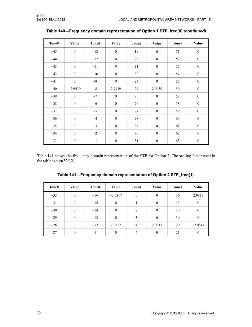
IEEEStd 802.15.4g-2012 LOCAL AND METROPOLITAN AREA NETWORKS—PART 15.4:
Table 141 shows the frequency domain representation of the STF for Option 2. The scaling factor used inthe table is sqrt(52/12).
–45 0 –13 0 19 0 51 0
–44 0 –12 0 20 0 52 0
–43 0 –11 0 21 0 53 0
–42 0 –10 0 22 0 54 0
–41 0 –9 0 23 0 55 0
–40 –2.9439 –8 2.9439 24 2.9439 56 0
–39 0 –7 0 25 0 57 0
–38 0 –6 0 26 0 58 0
–37 0 –5 0 27 0 59 0
–36 0 –4 0 28 0 60 0
–35 0 –3 0 29 0 61 0
–34 0 –2 0 30 0 62 0
–33 0 –1 0 31 0 63 0
Table 141—Frequency domain representation of Option 2 STF_freq(1)
Tone# Value Tone# Value Tone# Value Tone# Value
–32 0 –16 –2.0817 0 0 16 2.0817
–31 0 –15 0 1 0 17 0
–30 0 –14 0 2 0 18 0
–29 0 –13 0 3 0 19 0
–28 0 –12 2.0817 4 2.0817 20 –2.0817
–27 0 –11 0 5 0 21 0
Table 140—Frequency domain representation of Option 1 STF_freq(0) (continued)
Tone# Value Tone# Value Tone# Value Tone# Value
72 Copyright © 2012 IEEE. All rights reserved.

IEEEWIRELESS MAC AND PHY SPECIFICATIONS FOR LR-WPANS—AMENDMENT 3 Std 802.15.4g-2012
Table 142 shows the frequency domain representation of the STF for Option 3. The scaling factor used inthe table is sqrt(26/6).
Table 143 shows the frequency domain representation of the STF for Option 4. The scaling factor used inthe table is sqrt(14/6).
18.2.1.1.2 Time domain STF generation
Given a sequence of N samples f(n), indexed by n = 0, ..., N – 1, the discrete Fourier transform (DFT) isdefined as F(k), where k = 0, ..., N – 1:
–26 0 –10 0 6 0 22 0
–25 0 –9 0 7 0 23 0
–24 –2.0817 –8 2.0817 8 –2.0817 24 2.0817
–23 0 –7 0 9 0 25 0
–22 0 –6 0 10 0 26 0
–21 0 –5 0 11 0 27 0
–20 –2.0817 –4 2.0817 12 2.0817 28 0
–19 0 –3 0 13 0 29 0
–18 0 –2 0 14 0 30 0
–17 0 –1 0 15 0 31 0
Table 142—Frequency domain representation of Option 3 STF_freq(2)
Tone# Value Tone# Value Tone# Value Tone# Value
–16 0 –8 2.0817 0 0 8 2.0817
–15 0 –7 0 1 0 9 0
–14 0 –6 0 2 0 10 0
–13 0 –5 0 3 0 11 0
–12 2.0817 –4 2.0817 4 –2.0817 12 –2.0817
–11 0 –3 0 5 0 13 0
–10 0 –2 0 6 0 14 0
–9 0 –1 0 7 0 15 0
Table 141—Frequency domain representation of Option 2 STF_freq(1) (continued)
Tone# Value Tone# Value Tone# Value Tone# Value
F k( ) 1
N-------- f n( )e
j2πkn N⁄–
n 0=
N 1–
=
Copyright © 2012 IEEE. All rights reserved. 73

IEEEStd 802.15.4g-2012 LOCAL AND METROPOLITAN AREA NETWORKS—PART 15.4:
The sequence f(n) can be calculated from F(k) using the inverse discrete Fourier transform (IDFT), wherethe k values numbered from 0 to (N / 2) – 1 correspond to tones numbered from 0 to (N / 2) – 1 and the kvalues numbered from (N / 2) to (N – 1) correspond to tones numbered from –(N / 2) to –1, respectively:
The time domain STF for Option-n (n = 1, 2, 3, 4) is obtained as follows:
STF_time(Option-n) = IDFT(STF_freq(Option-n))
The CP is then prepended to the OFDM symbol.
18.2.1.1.3 Time domain STF repetition
There are four STF OFDM symbols, and the last 1/2 of the fourth OFDM symbol is negated in the timedomain. For Options 2, 3, and 4, the CP is 1/4 of the OFDM symbol. Therefore, for Options 2 and 3, thereare 18 repetitions of the 1/4 STF symbol followed by the last 1/2 of the fourth OFDM symbol, which isnegated in the time domain. For Option 4, there are nine repetitions of the 1/2 STF symbol followed by thelast 1/2 of the fourth OFDM symbol, which is negated in the time domain.
For Option 1, the CP is also 1/4 symbol, and the STF repetition is eight times per STF symbol. Therefore,there are 36 repetitions of 1/8 STF symbol in the four STF symbols followed by the last 1/2 of the fourthOFDM symbol, which is negated in the time domain.
Figure 129 shows the STF structure for all four options. Each “s” in the figure represents one time-domainrepetition of a subsequence of different length for MR-OFDM Option 1, Option 2 & 3, and Option 4.
18.2.1.1.4 STF normalization
The STF uses a lesser number of tones than the DATA field. Hence, normalization of the frequency domainSTF is required to ensure that the STF power is the same as the rest of the packet. In order to have the samepower as the DATA field, the normalization value is as follows:
where Nactive is the number of used subcarriers in rest of the OFDM packet for the particular DFT option
Nstf is the number of subcarriers used in the STF.
Table 143—Frequency domain representation of Option 4 STF_freq(3)
Tone# Value Tone# Value Tone# Value Tone# Value
–8 0 –4 1.5275 0 0 4 1.5275
–7 0 –3 0 1 0 5 0
–6 1.5275 –2 1.5275 2 –1.5275 6 –1.5275
–5 0 –1 0 3 0 7 0
f n( ) 1
N-------- F k( )ej2πnk N⁄
k 0=
N 1–
=
sqrt Nactive Nstf⁄( )
74 Copyright © 2012 IEEE. All rights reserved.
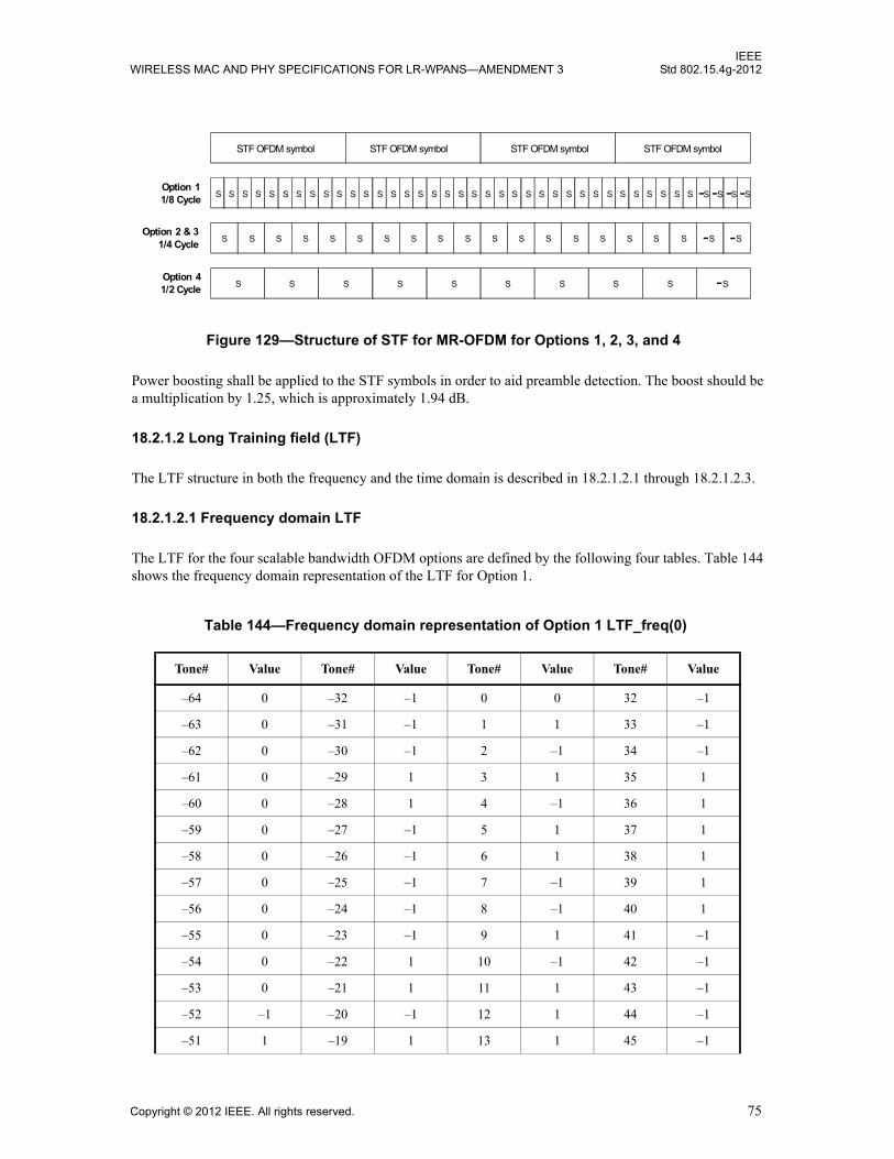
IEEEWIRELESS MAC AND PHY SPECIFICATIONS FOR LR-WPANS—AMENDMENT 3 Std 802.15.4g-2012
Power boosting shall be applied to the STF symbols in order to aid preamble detection. The boost should bea multiplication by 1.25, which is approximately 1.94 dB.
18.2.1.2 Long Training field (LTF)
The LTF structure in both the frequency and the time domain is described in 18.2.1.2.1 through 18.2.1.2.3.
18.2.1.2.1 Frequency domain LTF
The LTF for the four scalable bandwidth OFDM options are defined by the following four tables. Table 144shows the frequency domain representation of the LTF for Option 1.
Table 144—Frequency domain representation of Option 1 LTF_freq(0)
Tone# Value Tone# Value Tone# Value Tone# Value
–64 0 –32 –1 0 0 32 –1
–63 0 –31 –1 1 1 33 –1
–62 0 –30 –1 2 –1 34 –1
–61 0 –29 1 3 1 35 1
–60 0 –28 1 4 –1 36 1
–59 0 –27 –1 5 1 37 1
–58 0 –26 –1 6 1 38 1
–57 0 –25 –1 7 –1 39 1
–56 0 –24 –1 8 –1 40 1
–55 0 –23 –1 9 1 41 –1
–54 0 –22 1 10 –1 42 –1
–53 0 –21 1 11 1 43 –1
–52 –1 –20 –1 12 1 44 –1
–51 1 –19 1 13 1 45 –1
Figure 129—Structure of STF for MR-OFDM for Options 1, 2, 3, and 4
STF OFDM symbol STF OFDM symbol STF OFDM symbol STF OFDM symbol
S S S S S S S S S S S S S S S S S S S S S S S S S S S S S S S S S S S S -S -S -S -SOption 11/8 Cycle
S S S S S S S S S S S S S S S S S S -S SOption 2 & 3
1/4 Cycle
S S S S S S S S S -SOption 4 1/2 Cycle
-
Copyright © 2012 IEEE. All rights reserved. 75
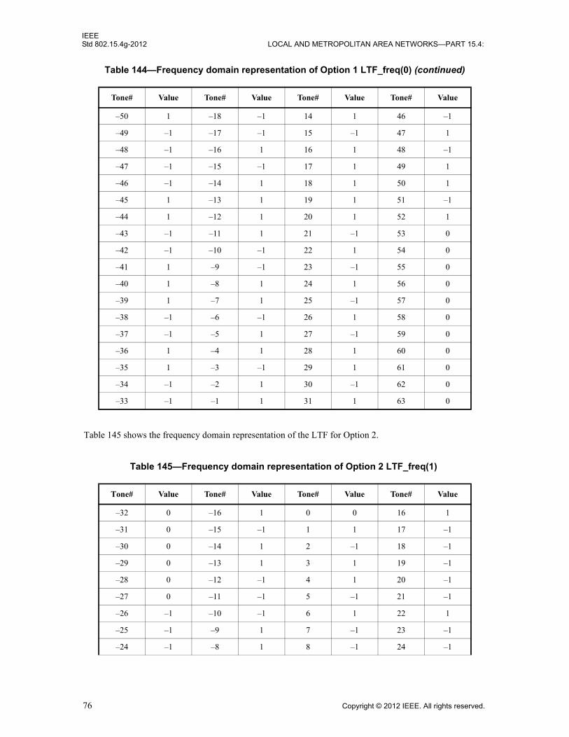
IEEEStd 802.15.4g-2012 LOCAL AND METROPOLITAN AREA NETWORKS—PART 15.4:
Table 145 shows the frequency domain representation of the LTF for Option 2.
–50 1 –18 –1 14 1 46 –1
–49 –1 –17 –1 15 –1 47 1
–48 –1 –16 1 16 1 48 –1
–47 –1 –15 –1 17 1 49 1
–46 –1 –14 1 18 1 50 1
–45 1 –13 1 19 1 51 –1
–44 1 –12 1 20 1 52 1
–43 –1 –11 1 21 –1 53 0
–42 –1 –10 –1 22 1 54 0
–41 1 –9 –1 23 –1 55 0
–40 1 –8 1 24 1 56 0
–39 1 –7 1 25 –1 57 0
–38 –1 –6 –1 26 1 58 0
–37 –1 –5 1 27 –1 59 0
–36 1 –4 1 28 1 60 0
–35 1 –3 –1 29 1 61 0
–34 –1 –2 1 30 –1 62 0
–33 –1 –1 1 31 1 63 0
Table 145—Frequency domain representation of Option 2 LTF_freq(1)
Tone# Value Tone# Value Tone# Value Tone# Value
–32 0 –16 1 0 0 16 1
–31 0 –15 –1 1 1 17 –1
–30 0 –14 1 2 –1 18 –1
–29 0 –13 1 3 1 19 –1
–28 0 –12 –1 4 1 20 –1
–27 0 –11 –1 5 –1 21 –1
–26 –1 –10 –1 6 1 22 1
–25 –1 –9 1 7 –1 23 –1
–24 –1 –8 1 8 –1 24 –1
Table 144—Frequency domain representation of Option 1 LTF_freq(0) (continued)
Tone# Value Tone# Value Tone# Value Tone# Value
76 Copyright © 2012 IEEE. All rights reserved.
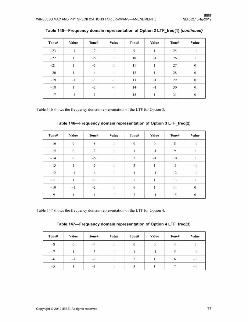
IEEEWIRELESS MAC AND PHY SPECIFICATIONS FOR LR-WPANS—AMENDMENT 3 Std 802.15.4g-2012
Table 146 shows the frequency domain representation of the LTF for Option 3.
Table 147 shows the frequency domain representation of the LTF for Option 4.
–23 –1 –7 –1 9 1 25 –1
–22 1 –6 1 10 –1 26 1
–21 1 –5 1 11 1 27 0
–20 1 –4 1 12 1 28 0
–19 –1 –3 –1 13 –1 29 0
–18 1 –2 –1 14 –1 30 0
–17 –1 –1 –1 15 1 31 0
Table 146—Frequency domain representation of Option 3 LTF_freq(2)
Tone# Value Tone# Value Tone# Value Tone# Value
–16 0 –8 1 0 0 8 –1
–15 0 –7 1 1 –1 9 1
–14 0 –6 1 2 –1 10 1
–13 1 –5 1 3 1 11 –1
–12 –1 –4 1 4 –1 12 –1
–11 1 –3 1 5 1 13 1
–10 –1 –2 1 6 1 14 0
–9 1 –1 –1 7 –1 15 0
Table 147—Frequency domain representation of Option 4 LTF_freq(3)
Tone# Value Tone# Value Tone# Value Tone# Value
–8 0 –4 1 0 0 4 1
–7 1 –3 –1 1 –1 5 –1
–6 –1 –2 1 2 1 6 –1
–5 1 –1 1 3 1 7 –1
Table 145—Frequency domain representation of Option 2 LTF_freq(1) (continued)
Tone# Value Tone# Value Tone# Value Tone# Value
Copyright © 2012 IEEE. All rights reserved. 77

IEEEStd 802.15.4g-2012 LOCAL AND METROPOLITAN AREA NETWORKS—PART 15.4:
18.2.1.2.2 Time domain LTF generation
The time domain LTF for Option-n (n = 1, 2, 3, 4) is obtained as follows:
LTF_time(Option-n) = IDFT(LTF_freq(Option-n)).
A 1/2 symbol CP is prepended to two consecutive copies of the base symbol as shown in Figure 130. Formore details, see 18.2.3.8.
The time-domain LTF structure is shown in Figure 130, and TDFT is the duration of the base symbol.
18.2.1.2.3 LTF normalization
Power boosting is not used by the LTF.
18.2.1.3 PHR
The PHR consists of the Frame Length field and frame control bits. The PHR structure shall be formatted asillustrated in Figure 131. All multi-bit fields are unsigned integers and shall be processed MSB first.
When the PIB attribute phyOFDMInterleaving, as defined in 9.3, is zero (i.e., interleaving depth of onesymbol), the PHR occupies three OFDM symbols for Option 1 and six OFDM symbols for Options 2, 3, and4. When the PIB attribute phyOFDMInterleaving is one (i.e., interleaving depth of the number of symbolsequal to the frequency domain spreading factor), the PHR occupies four OFDM symbols for Option 1, eightOFDM symbols for Option 2, and six OFDM symbols for Options 3 and 4. The PHR shall be transmittedusing the lowest supported modulation and coding scheme (MCS) level, as described in Table 148, for the
Bit stringindex
0–4 5 6–16 17–18 19–20 21 22–29 30–35
Bit mapping
RA4–RA0 R L10–L0 R1–R0 S1–S0 R H7–H0 T5–T0
Fieldname
Rate Reserved Frame Length
Reserved Scrambler Reserved HCS Tail
Figure 131—PHY header fields for MR-OFDM
Figure 130—Structure of LTF for MR-OFDM
TDFT
LTF LTF
TDFTTDFT / 2
Double length CP
78 Copyright © 2012 IEEE. All rights reserved.

IEEEWIRELESS MAC AND PHY SPECIFICATIONS FOR LR-WPANS—AMENDMENT 3 Std 802.15.4g-2012
option being used. It is sent to the convolutional encoder starting from the leftmost bit in Figure 131 to therightmost bit.
The Rate field (RA4–RA0) specifies the data rate of the payload and is equal to the numerical value of theMCS, as described in 18.2.3, expressed in binary format. The list of data rates for each OFDM bandwidthoption can be found in 18.2.2.
The Frame Length field (L10–L0) specifies the total number of octets contained in the PSDU (prior to FECencoding).
The Scrambler field (S1–S0) specifies the scrambling seed, as described in 18.2.3.11.
The Header Check Sequence (HCS) field (H7–H0) is an 8-bit CRC taken over the PHY header (PHR) fields.
The HCS shall be computed using the first 22 bits of the PHR. The HCS shall be calculated using thepolynomial G8(x) = x8 + x2 + x + 1.
The HCS is the one’s complement of the modulo 2 sum of the two remainders in a) and b):
a) The remainder resulting from [xk(x7+x6+…+1)] divided (modulo 2) by G8(x), where the value k isthe number of bits in the calculation field.
b) The remainder resulting from the calculation field contents, treated as a polynomial, multiplied byx8 and then divided (modulo 2) by G8(x).
At the transmitter, the initial remainder of the division shall be preset to all ones and then be modified viadivision of the calculation field by the generator polynomial G8(x). The one’s complement of this remainderis the HCS field. An example of HCS generation is given in L.3.1.
The Tail bit field (T5–T0), which consists of all zeros, is for Viterbi decoder flushing, as described in18.2.3.9.
18.2.1.4 PSDU field
The PSDU field carries the data of the PHY packet.
18.2.2 Data rates for MR-OFDM
There are four OFDM options, each with a different number of active tones. All devices supporting aparticular option (1, 2, 3, or 4) shall support all BPSK and QPSK modulation and coding scheme (MCS)levels for that option. All 16 quadrature amplitude modulation (QAM) MCS levels are optional.
The various data rates are shown in Table 148. The nominal bandwidth is calculated by multiplying {thenumber of active tones + 1 for the DC tone} by {the subcarrier spacing}.
Copyright © 2012 IEEE. All rights reserved. 79

IEEEStd 802.15.4g-2012 LOCAL AND METROPOLITAN AREA NETWORKS—PART 15.4:
Table 148—Data Rates for MR-OFDM PHY
ParameterOFDM
Option 1OFDM
Option 2OFDM
Option 3OFDM
Option 4
Nominal bandwidth (kHz) 1094 552 281 156
Channel spacing (kHz) 1200 800 400 200
DFT size 128 64 32 16
Active tones 104 52 26 14
# Pilot tones 8 4 2 2
# Data tones 96 48 24 12
MCS0 (kb/s)(BPSK rate 1/2 with 4x frequency repetition) 100 50 — —
MCS1 (kb/s)(BPSK rate 1/2 with 2x frequency repetition) 200 100 50 —
MCS2 (kb/s)(QPSK rate 1/2 and 2x frequency repetition)
400 200 100 50
MCS3 (kb/s)(QPSK rate 1/2) 800 400 200 100
MCS4 (kb/s)(QPSK rate 3/4) — 600 300 150
MCS5 (kb/s)(16-QAM rate 1/2)
— 800 400 200
MCS6 (kb/s)(16-QAM rate 3/4) — — 600 300
80 Copyright © 2012 IEEE. All rights reserved.

IEEEWIRELESS MAC AND PHY SPECIFICATIONS FOR LR-WPANS—AMENDMENT 3 Std 802.15.4g-2012
18.2.3 Modulation and coding for MR-OFDM
18.2.3.1 Reference modulator diagram
The reference modulator diagram is shown in Figure 132.
Figure 132—Reference modulator diagram for MR-OFDM
Generate Header 16.2.1.3
Pilot, DC, and guard tones 16.2.3.7
IEEE Std802.15.4 MAC
Scrambler 16.2.3.11
Encoder 16.2.3.4
Puncturer16.2.3.4
DAC / RF Transceiver / PA
FilteringCyclic Prefix Insertion 16.2.3.8
IDFT 16.2.1.1.2
Subcarrier Modulation Mapper 16.2.3.2
Interleaver16.2.3.5
Frequency Domain Spreading 16.2.3.6
STF Frequency Domain 16.2.1.1
LTF Frequency Domain 16.2.1.2
Data bits
Data rate, Frame length
Copyright © 2012 IEEE. All rights reserved. 81
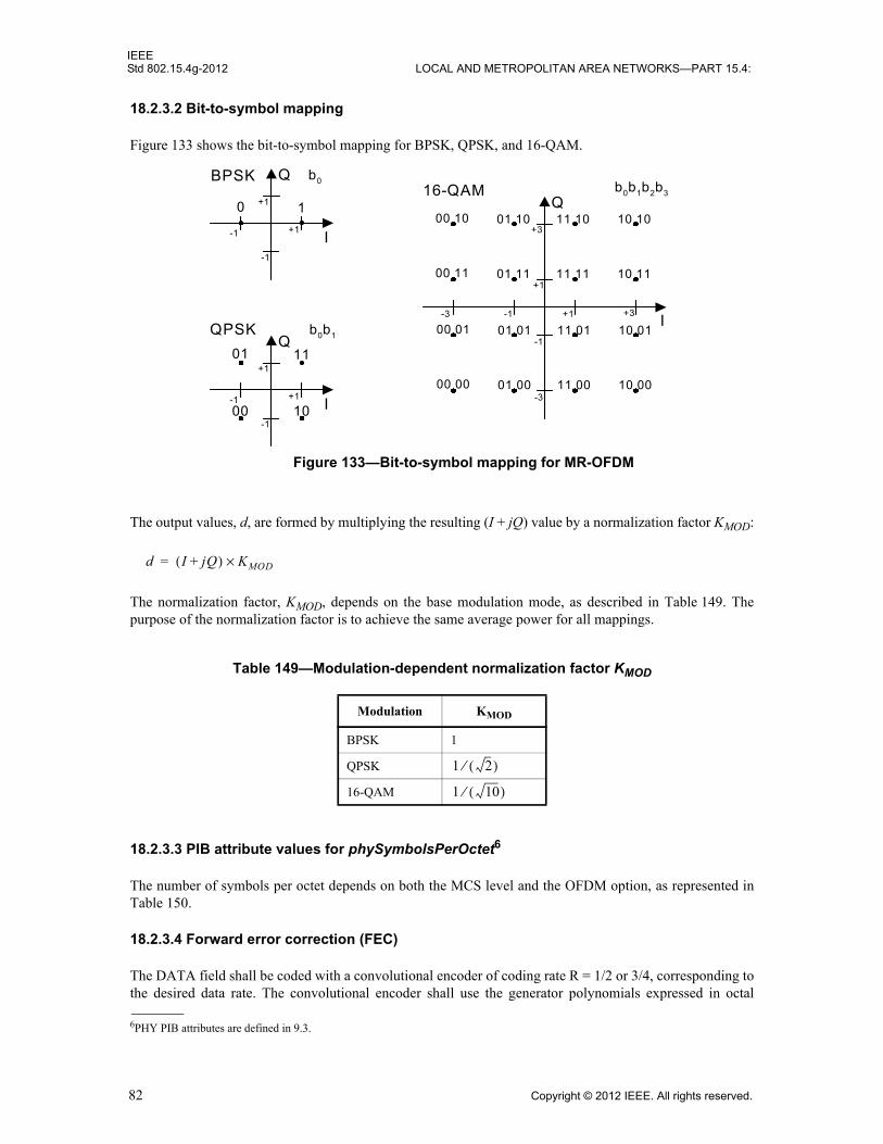
IEEEStd 802.15.4g-2012 LOCAL AND METROPOLITAN AREA NETWORKS—PART 15.4:
18.2.3.2 Bit-to-symbol mapping
Figure 133 shows the bit-to-symbol mapping for BPSK, QPSK, and 16-QAM.
The output values, d, are formed by multiplying the resulting (I + jQ) value by a normalization factor KMOD:
The normalization factor, KMOD, depends on the base modulation mode, as described in Table 149. Thepurpose of the normalization factor is to achieve the same average power for all mappings.
18.2.3.3 PIB attribute values for phySymbolsPerOctet6
The number of symbols per octet depends on both the MCS level and the OFDM option, as represented inTable 150.
18.2.3.4 Forward error correction (FEC)
The DATA field shall be coded with a convolutional encoder of coding rate R = 1/2 or 3/4, corresponding tothe desired data rate. The convolutional encoder shall use the generator polynomials expressed in octal
Table 149—Modulation-dependent normalization factor KMOD
Modulation KMOD
BPSK 1
QPSK
16-QAM
6PHY PIB attributes are defined in 9.3.
+1
+1-1
-1
10
I
QBPSK
+1
+1-1
-1
01
I
QQPSK
+3
+1-1
+1
I
Q16-QAM
b0
b0b1
11
1000
-1
-3
+3-3
b0b1b2b3
00 10
00 11
00 01
00 00
01 10
01 11
01 01
01 00
11 10
11 11
11 01
11 00
10 10
10 11
10 01
10 00
Figure 133—Bit-to-symbol mapping for MR-OFDM
d I jQ+( ) KMOD×=
1 2( )⁄
1 10( )⁄
82 Copyright © 2012 IEEE. All rights reserved.
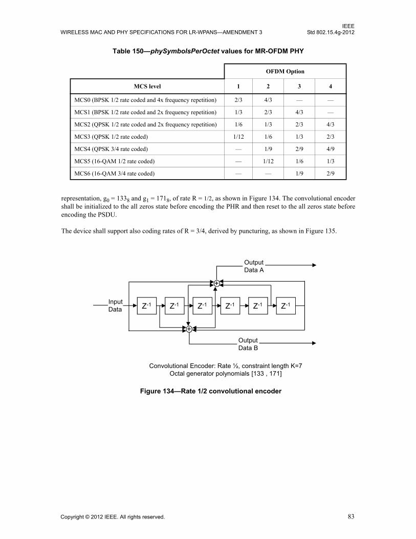
IEEEWIRELESS MAC AND PHY SPECIFICATIONS FOR LR-WPANS—AMENDMENT 3 Std 802.15.4g-2012
representation, g0 = 1338 and g1 = 1718, of rate R = 1/2, as shown in Figure 134. The convolutional encodershall be initialized to the all zeros state before encoding the PHR and then reset to the all zeros state beforeencoding the PSDU.
The device shall support also coding rates of R = 3/4, derived by puncturing, as shown in Figure 135.
Table 150—phySymbolsPerOctet values for MR-OFDM PHY
OFDM Option
MCS level 1 2 3 4
MCS0 (BPSK 1/2 rate coded and 4x frequency repetition) 2/3 4/3 — —
MCS1 (BPSK 1/2 rate coded and 2x frequency repetition) 1/3 2/3 4/3 —
MCS2 (QPSK 1/2 rate coded and 2x frequency repetition) 1/6 1/3 2/3 4/3
MCS3 (QPSK 1/2 rate coded) 1/12 1/6 1/3 2/3
MCS4 (QPSK 3/4 rate coded) — 1/9 2/9 4/9
MCS5 (16-QAM 1/2 rate coded) — 1/12 1/6 1/3
MCS6 (16-QAM 3/4 rate coded) — — 1/9 2/9
Figure 134—Rate 1/2 convolutional encoder
Z-1 Z-1 Z-1 Z-1 Z-1 Z-1Input Data
+
+
Output Data B
Output Data A
Convolutional Encoder: Rate ½, constraint length K=7 Octal generator polynomials [133 , 171]
Copyright © 2012 IEEE. All rights reserved. 83

IEEEStd 802.15.4g-2012 LOCAL AND METROPOLITAN AREA NETWORKS—PART 15.4:
18.2.3.5 Interleaver
The interleaving process consists of two permutations. The index of the coded bit before the firstpermutation shall be denoted as k; i shall be the index after the first and before the second permutation; and jshall be the index after the second permutation, just prior to modulation mapping. The coded bits are writtenat the index given by j, and read out sequentially. The index i is defined as follows:
where Ncbps is the number of coded bits per symbol before any frequency spreading
k is 0, 1, 2,..., (Ncbps - 1)
Nrow is 12 when no frequency spreading is used or 12 / (spreading factor) when spreading is used
The index j is defined as follows:
where Ncbps is the number of coded bits per symbol before any frequency spreading
i is0, 1, 2, …, Ncbps-1
Nrow is 12 when no frequency spreading is used or 12 / (spreading factor) when spreading is used
and
Figure 135—Puncturing for rate 3/4
Source Data
Encoded Data
Bit Stolen Data
sent/received
Bit Inserted Data
Decoded Data
X0 X1 X2 X3 X4 X5
A0 A1 A2 A3 A4 A5
B0 B1 B2 B3 B4 B5
Stolen Bit
Inserted Dum m y Bit
A0 B0 A1 B2 A3 B3 A4 B5
A0 A1 A2 A3 A4 A5
B0 B1 B2 B3 B4 B5
y0 y1 y2 y3 y4 y5
iNcbps
Nrow------------ k mod Nrow( )[ ]× floor
kNrow----------- +=
j s flooris-- × i Ncbps floor
Nrow i×Ncbps
------------------- –+ mod s( )+=
s maxNbpsc
2------------ 1, =
84 Copyright © 2012 IEEE. All rights reserved.
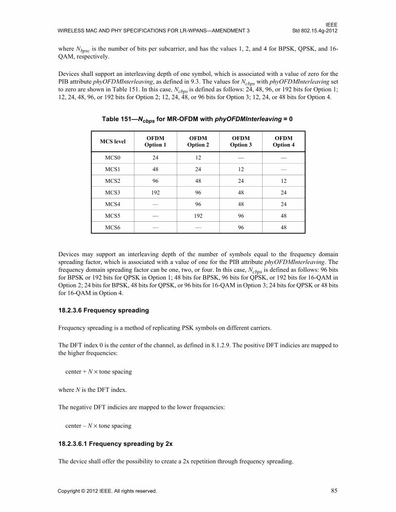
IEEEWIRELESS MAC AND PHY SPECIFICATIONS FOR LR-WPANS—AMENDMENT 3 Std 802.15.4g-2012
where Nbpsc is the number of bits per subcarrier, and has the values 1, 2, and 4 for BPSK, QPSK, and 16-QAM, respectively.
Devices shall support an interleaving depth of one symbol, which is associated with a value of zero for thePIB attribute phyOFDMInterleaving, as defined in 9.3. The values for Ncbps with phyOFDMInterleaving setto zero are shown in Table 151. In this case, Ncbps is defined as follows: 24, 48, 96, or 192 bits for Option 1;12, 24, 48, 96, or 192 bits for Option 2; 12, 24, 48, or 96 bits for Option 3; 12, 24, or 48 bits for Option 4.
Devices may support an interleaving depth of the number of symbols equal to the frequency domainspreading factor, which is associated with a value of one for the PIB attribute phyOFDMInterleaving. Thefrequency domain spreading factor can be one, two, or four. In this case, Ncbps is defined as follows: 96 bitsfor BPSK or 192 bits for QPSK in Option 1; 48 bits for BPSK, 96 bits for QPSK, or 192 bits for 16-QAM inOption 2; 24 bits for BPSK, 48 bits for QPSK, or 96 bits for 16-QAM in Option 3; 24 bits for QPSK or 48 bitsfor 16-QAM in Option 4.
18.2.3.6 Frequency spreading
Frequency spreading is a method of replicating PSK symbols on different carriers.
The DFT index 0 is the center of the channel, as defined in 8.1.2.9. The positive DFT indicies are mapped tothe higher frequencies:
where N is the DFT index.
The negative DFT indicies are mapped to the lower frequencies:
18.2.3.6.1 Frequency spreading by 2x
The device shall offer the possibility to create a 2x repetition through frequency spreading.
Table 151—Ncbps for MR-OFDM with phyOFDMInterleaving = 0
MCS level OFDM Option 1
OFDM Option 2
OFDM Option 3
OFDM Option 4
MCS0 24 12 — —
MCS1 48 24 12 —
MCS2 96 48 24 12
MCS3 192 96 48 24
MCS4 — 96 48 24
MCS5 — 192 96 48
MCS6 — — 96 48
center N tone spacing×+
center N tone spacing×–
Copyright © 2012 IEEE. All rights reserved. 85

IEEEStd 802.15.4g-2012 LOCAL AND METROPOLITAN AREA NETWORKS—PART 15.4:
The spreading is performed by first separating out the data tones from the pilot tones. The data tones arerenumbered from –Nd / 2 to –1 and 1 to Nd / 2, where Nd is the number of data tones in an OFDM symbol. Asan example with Option 3, there are two pilot tones and 24 data tones with indices from –13 to 13 excludingthe DC tone. Therefore, the data tones are renumbered as d-12, d-11, d-10, d-9, d-8, d-7, d-6, d-5, d-4, d-3, d-2, d-1,and d1,d2, d3, d4, d5, d6, d7, d8, d9, d10, d11, d12. The DC tone is omitted since it is not used in any of theOFDM options.
The data tones to be transmitted in the OFDM symbol are placed into the positive data tones (numberedfrom 1 to Nd / 2). Phase rotations are applied after copying the data tones to the negative frequencies, inorder to reduce the peak-to-average power ratio of the OFDM symbol with frequency spreading. The datatones are given by
where k = 1, ..., Nd / 2.
18.2.3.6.2 Frequency spreading by 4x
The device shall offer the possibility to create a 4x repetition through frequency spreading.
As with frequency spreading by 2x, the data tones are separated from the pilot tones and renumbered. Thedata tones to be transmitted in the OFDM symbol are placed into the lower half of the positive data tones(numbered from 1 to Nd / 4). Phase rotations are applied after copying the data tones to the negativefrequencies and upper half of the positive frequencies, in order to reduce the peak-to-average power ratio ofthe OFDM symbol with frequency spreading.
where k = 1, ..., Nd / 4.
where k = 1, ..., Nd / 4.
where k = 1, ..., Nd / 4.
18.2.3.6.3 No spreading
The device shall offer the possibility to map a symbol into tones without frequency spreading.
The data tones to be transmitted in the OFDM symbol are placed into the negative data tones (numberedfrom –Nd / 2 to –1) followed by the positive data tones (numbered 1 to Nd / 2).
18.2.3.7 Pilot tones / null tones
The number of pilot and null tones for each OFDM option are defined as shown in Table 152.
The pilot tones shall be transmitted with different shifts in the frequency domain, in order to enable channelestimation when the channel is changing due to Doppler. Immediately after the second LTF, the pilot shifts
d k Nd 2⁄[ ]– 1–( ) dke j2π 2 k 1–×( ) 4⁄[ ]=
d k Nd 4⁄+( ) dke j2π k 1–( ) 4⁄[ ]=
d k Nd 2⁄[ ]– 1–( ) dke j2π 2 k 1–×( ) 4⁄[ ]=
d k Nd 4⁄[ ]– 1–( ) dke j2π 3 k 1–×( ) 4⁄[ ]=
86 Copyright © 2012 IEEE. All rights reserved.
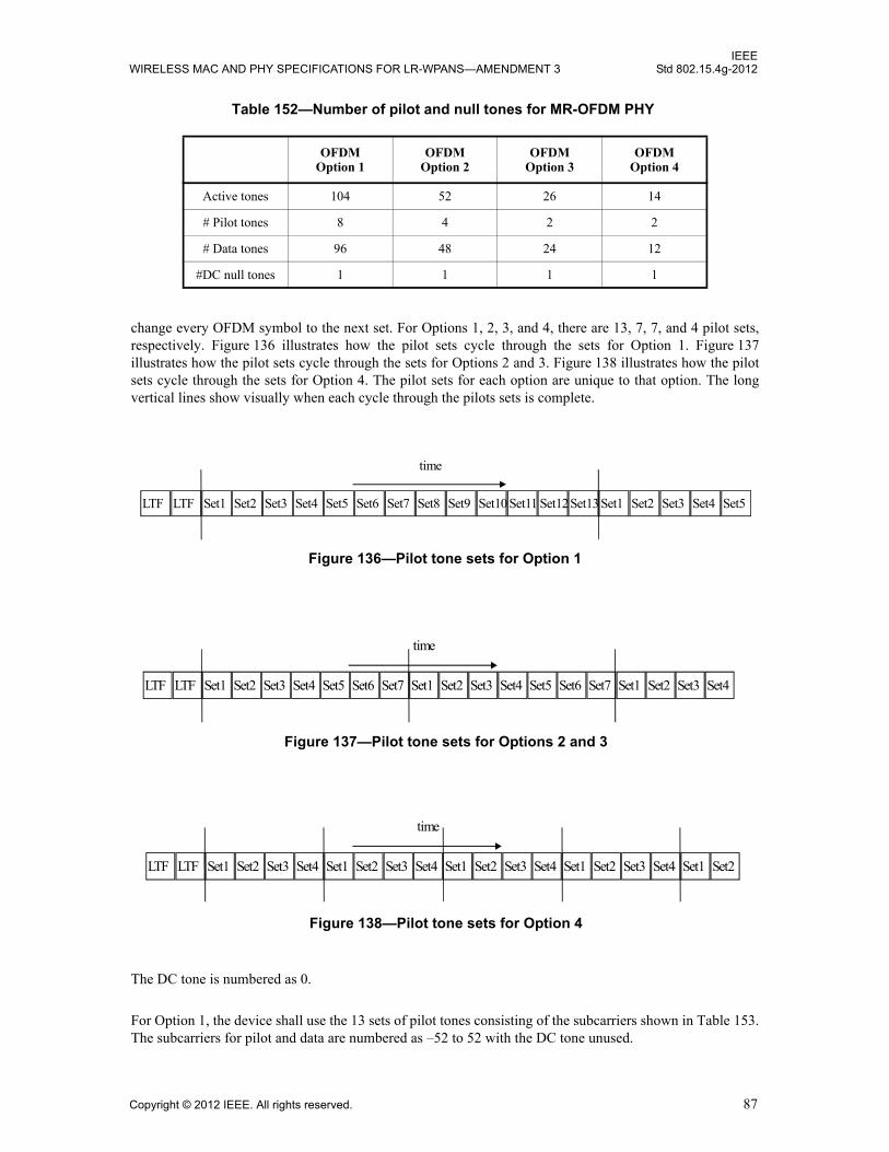
IEEEWIRELESS MAC AND PHY SPECIFICATIONS FOR LR-WPANS—AMENDMENT 3 Std 802.15.4g-2012
change every OFDM symbol to the next set. For Options 1, 2, 3, and 4, there are 13, 7, 7, and 4 pilot sets,respectively. Figure 136 illustrates how the pilot sets cycle through the sets for Option 1. Figure 137illustrates how the pilot sets cycle through the sets for Options 2 and 3. Figure 138 illustrates how the pilotsets cycle through the sets for Option 4. The pilot sets for each option are unique to that option. The longvertical lines show visually when each cycle through the pilots sets is complete.
The DC tone is numbered as 0.
For Option 1, the device shall use the 13 sets of pilot tones consisting of the subcarriers shown in Table 153.The subcarriers for pilot and data are numbered as –52 to 52 with the DC tone unused.
Table 152—Number of pilot and null tones for MR-OFDM PHY
OFDMOption 1
OFDMOption 2
OFDMOption 3
OFDMOption 4
Active tones 104 52 26 14
# Pilot tones 8 4 2 2
# Data tones 96 48 24 12
#DC null tones 1 1 1 1
LTF LTF Set1 Set2 Set3 Set4 Set5 Set6 Set7 Set8 Set9 Set10 Set11 Set12Set13Set1 Set2 Set4 Set5Set3
time
Figure 136—Pilot tone sets for Option 1
LTF LTF Set1 Set2 Set3 Set4 Set5 Set6 Set7 Set1 Set2 Set3 Set4 Set5 Set6 Set7 Set1 Set3 Set4Set2
time
Figure 137—Pilot tone sets for Options 2 and 3
Figure 138—Pilot tone sets for Option 4
LTF LTF Set1 Set2 Set3 Set4 Set1 Set2 Set3 Set4 Set1 Set2 Set3 Set4 Set1 Set2 Set3 Set1 Set2Set4
time
Copyright © 2012 IEEE. All rights reserved. 87
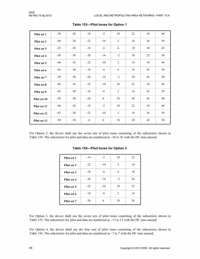
IEEEStd 802.15.4g-2012 LOCAL AND METROPOLITAN AREA NETWORKS—PART 15.4:
For Option 2, the device shall use the seven sets of pilot tones consisting of the subcarriers shown inTable 154. The subcarriers for pilot and data are numbered as –26 to 26 with the DC tone unused.
For Option 3, the device shall use the seven sets of pilot tones consisting of the subcarriers shown inTable 155. The subcarriers for pilot and data are numbered as –13 to 13 with the DC tone unused.
For Option 4, the device shall use the four sets of pilot tones consisting of the subcarriers shown inTable 156. The subcarriers for pilot and data are numbered as –7 to 7 with the DC tone unused.
Table 153—Pilot tones for Option 1
Pilot set 1 –38 –26 –14 –2 10 22 34 46
Pilot set 2 –46 –34 –22 –10 2 14 26 38
Pilot set 3 –42 –30 –18 –6 6 18 30 42
Pilot set 4 –50 –38 –26 –14 –2 10 22 50
Pilot set 5 –46 –34 –22 –10 2 14 34 46
Pilot set 6 –42 –30 –18 –6 6 18 26 38
Pilot set 7 –50 –38 –26 –14 –2 30 42 50
Pilot set 8 –46 –34 –22 –10 10 22 34 46
Pilot set 9 –42 –30 –18 –6 2 14 26 38
Pilot set 10 –50 –38 –26 6 18 30 42 50
Pilot set 11 –46 –34 –14 –2 10 22 34 46
Pilot set 12 –42 –30 –22 –10 2 14 26 38
Pilot set 13 –50 –18 –6 6 18 30 42 50
Table 154—Pilot tones for Option 2
Pilot set 1 –14 –2 10 22
Pilot set 2 –22 –10 2 14
Pilot set 3 –18 –6 6 18
Pilot set 4 –26 –14 –2 26
Pilot set 5 –22 –10 10 22
Pilot set 6 –18 –6 2 14
Pilot set 7 –26 6 18 26
88 Copyright © 2012 IEEE. All rights reserved.
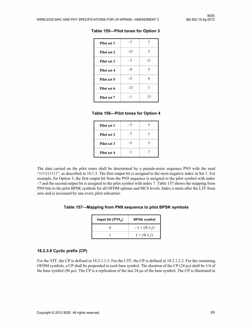
IEEEWIRELESS MAC AND PHY SPECIFICATIONS FOR LR-WPANS—AMENDMENT 3 Std 802.15.4g-2012
The data carried on the pilot tones shall be determined by a pseudo-noise sequence PN9 with the seed“111111111”, as described in 18.1.3. The first output bit is assigned to the most negative index in Set 1. Forexample, for Option 3, the first output bit from the PN9 sequence is assigned to the pilot symbol with index–7 and the second output bit is assigned to the pilot symbol with index 7. Table 157 shows the mapping fromPN9 bits to the pilot BPSK symbols for all OFDM options and MCS levels. Index n starts after the LTF fromzero and is increased by one every pilot subcarrier.
18.2.3.8 Cyclic prefix (CP)
For the STF, the CP is defined in 18.2.1.1.3. For the LTF, the CP is defined in 18.2.1.2.2. For the remainingOFDM symbols, a CP shall be prepended to each base symbol. The duration of the CP (24 μs) shall be 1/4 ofthe base symbol (96 μs). The CP is a replication of the last 24 μs of the base symbol. The CP is illustrated in
Table 155—Pilot tones for Option 3
Pilot set 1 –7 7
Pilot set 2 –11 3
Pilot set 3 –3 11
Pilot set 4 –9 5
Pilot set 5 –5 9
Pilot set 6 –13 1
Pilot set 7 –1 13
Table 156—Pilot tones for Option 4
Pilot set 1 –3 5
Pilot set 2 –7 1
Pilot set 3 –5 3
Pilot set 4 –1 7
Table 157—Mapping from PN9 sequence to pilot BPSK symbols
Input bit (PN9n) BPSK symbol
0
1
1– 0 j×( )+
1 0 j×( )+
Copyright © 2012 IEEE. All rights reserved. 89
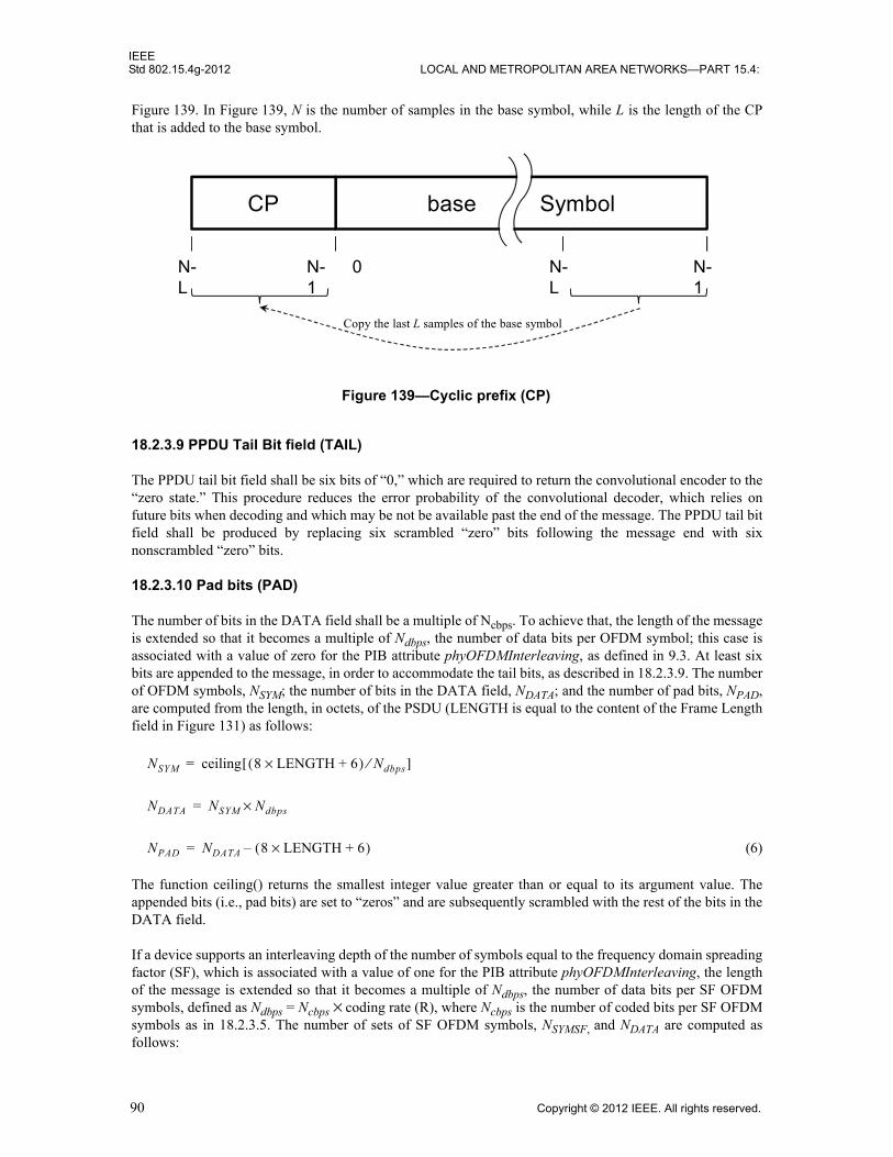
IEEEStd 802.15.4g-2012 LOCAL AND METROPOLITAN AREA NETWORKS—PART 15.4:
Figure 139. In Figure 139, N is the number of samples in the base symbol, while L is the length of the CPthat is added to the base symbol.
18.2.3.9 PPDU Tail Bit field (TAIL)
The PPDU tail bit field shall be six bits of “0,” which are required to return the convolutional encoder to the“zero state.” This procedure reduces the error probability of the convolutional decoder, which relies onfuture bits when decoding and which may be not be available past the end of the message. The PPDU tail bitfield shall be produced by replacing six scrambled “zero” bits following the message end with sixnonscrambled “zero” bits.
18.2.3.10 Pad bits (PAD)
The number of bits in the DATA field shall be a multiple of Ncbps. To achieve that, the length of the messageis extended so that it becomes a multiple of Ndbps, the number of data bits per OFDM symbol; this case isassociated with a value of zero for the PIB attribute phyOFDMInterleaving, as defined in 9.3. At least sixbits are appended to the message, in order to accommodate the tail bits, as described in 18.2.3.9. The numberof OFDM symbols, NSYM; the number of bits in the DATA field, NDATA; and the number of pad bits, NPAD,are computed from the length, in octets, of the PSDU (LENGTH is equal to the content of the Frame Lengthfield in Figure 131) as follows:
(6)
The function ceiling() returns the smallest integer value greater than or equal to its argument value. Theappended bits (i.e., pad bits) are set to “zeros” and are subsequently scrambled with the rest of the bits in theDATA field.
If a device supports an interleaving depth of the number of symbols equal to the frequency domain spreadingfactor (SF), which is associated with a value of one for the PIB attribute phyOFDMInterleaving, the lengthof the message is extended so that it becomes a multiple of Ndbps, the number of data bits per SF OFDMsymbols, defined as Ndbps = Ncbps × coding rate (R), where Ncbps is the number of coded bits per SF OFDMsymbols as in 18.2.3.5. The number of sets of SF OFDM symbols, NSYMSF, and NDATA are computed asfollows:
Figure 139—Cyclic prefix (CP)
base SymbolCP
0 N-1
N-L
N-L
N-1
Copy the last L samples of the base symbol
aaaaaaaaaaaaaaaaaaaaaaaaaaaa
NSYM ceiling 8 LENGTH 6+×( ) Ndbps⁄[ ]=
NDATA NSYM Ndbps×=
NPAD NDATA 8 LENGTH 6+×( )–=
90 Copyright © 2012 IEEE. All rights reserved.
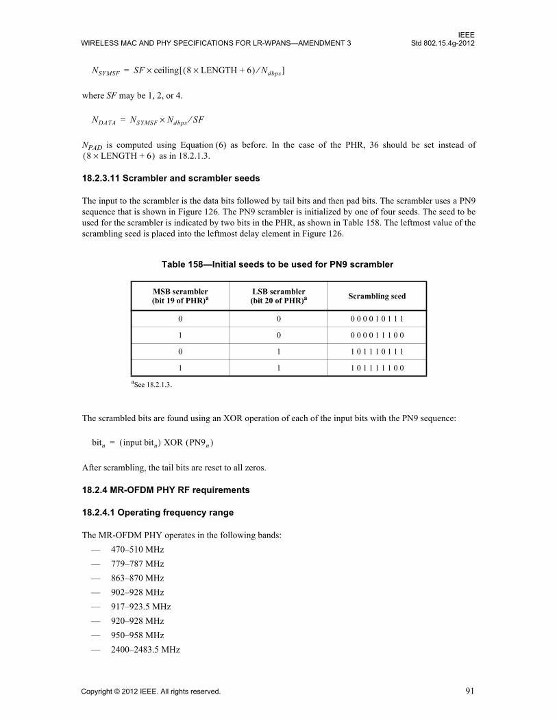
IEEEWIRELESS MAC AND PHY SPECIFICATIONS FOR LR-WPANS—AMENDMENT 3 Std 802.15.4g-2012
where SF may be 1, 2, or 4.
NPAD is computed using Equation (6) as before. In the case of the PHR, 36 should be set instead of as in 18.2.1.3.
18.2.3.11 Scrambler and scrambler seeds
The input to the scrambler is the data bits followed by tail bits and then pad bits. The scrambler uses a PN9sequence that is shown in Figure 126. The PN9 scrambler is initialized by one of four seeds. The seed to beused for the scrambler is indicated by two bits in the PHR, as shown in Table 158. The leftmost value of thescrambling seed is placed into the leftmost delay element in Figure 126.
The scrambled bits are found using an XOR operation of each of the input bits with the PN9 sequence:
After scrambling, the tail bits are reset to all zeros.
18.2.4 MR-OFDM PHY RF requirements
18.2.4.1 Operating frequency range
The MR-OFDM PHY operates in the following bands:
— 470–510 MHz
— 779–787 MHz
— 863–870 MHz
— 902–928 MHz
— 917–923.5 MHz
— 920–928 MHz
— 950–958 MHz
— 2400–2483.5 MHz
Table 158—Initial seeds to be used for PN9 scrambler
MSB scrambler(bit 19 of PHR)a
aSee 18.2.1.3.
LSB scrambler(bit 20 of PHR)a Scrambling seed
0 0 0 0 0 0 1 0 1 1 1
1 0 0 0 0 0 1 1 1 0 0
0 1 1 0 1 1 1 0 1 1 1
1 1 1 0 1 1 1 1 1 0 0
NSYMSF SF ceiling× 8 LENGTH 6+×( ) Ndbps⁄[ ]=
NDATA NSYMSF Ndbps× SF⁄=
8 LENGTH 6+×( )
bitn input bitn( ) XOR (PN9n )=
Copyright © 2012 IEEE. All rights reserved. 91
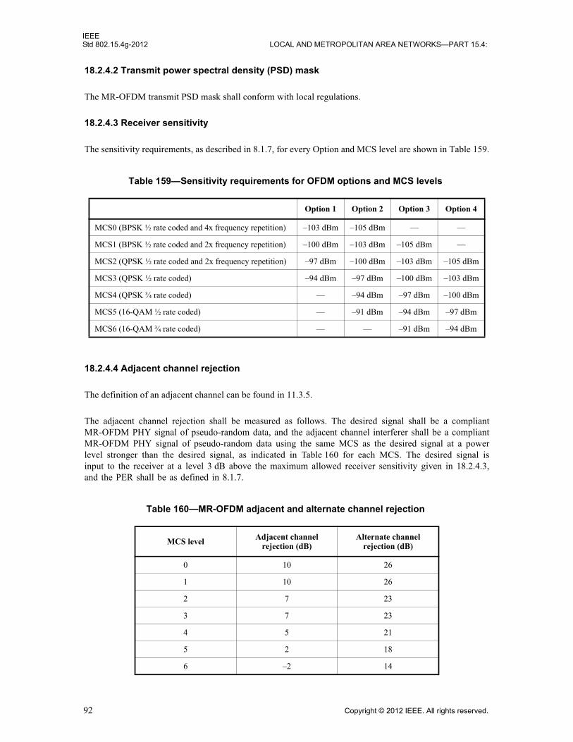
IEEEStd 802.15.4g-2012 LOCAL AND METROPOLITAN AREA NETWORKS—PART 15.4:
18.2.4.2 Transmit power spectral density (PSD) mask
The MR-OFDM transmit PSD mask shall conform with local regulations.
18.2.4.3 Receiver sensitivity
The sensitivity requirements, as described in 8.1.7, for every Option and MCS level are shown in Table 159.
18.2.4.4 Adjacent channel rejection
The definition of an adjacent channel can be found in 11.3.5.
The adjacent channel rejection shall be measured as follows. The desired signal shall be a compliantMR-OFDM PHY signal of pseudo-random data, and the adjacent channel interferer shall be a compliantMR-OFDM PHY signal of pseudo-random data using the same MCS as the desired signal at a powerlevel stronger than the desired signal, as indicated in Table 160 for each MCS. The desired signal isinput to the receiver at a level 3 dB above the maximum allowed receiver sensitivity given in 18.2.4.3,and the PER shall be as defined in 8.1.7.
Table 159—Sensitivity requirements for OFDM options and MCS levels
Option 1 Option 2 Option 3 Option 4
MCS0 (BPSK ½ rate coded and 4x frequency repetition) –103 dBm –105 dBm — —
MCS1 (BPSK ½ rate coded and 2x frequency repetition) –100 dBm –103 dBm –105 dBm —
MCS2 (QPSK ½ rate coded and 2x frequency repetition) –97 dBm –100 dBm –103 dBm –105 dBm
MCS3 (QPSK ½ rate coded) –94 dBm –97 dBm –100 dBm –103 dBm
MCS4 (QPSK ¾ rate coded) — –94 dBm –97 dBm –100 dBm
MCS5 (16-QAM ½ rate coded) — –91 dBm –94 dBm –97 dBm
MCS6 (16-QAM ¾ rate coded) — — –91 dBm –94 dBm
Table 160—MR-OFDM adjacent and alternate channel rejection
MCS level Adjacent channel rejection (dB)
Alternate channel rejection (dB)
0 10 26
1 10 26
2 7 23
3 7 23
4 5 21
5 2 18
6 –2 14
92 Copyright © 2012 IEEE. All rights reserved.
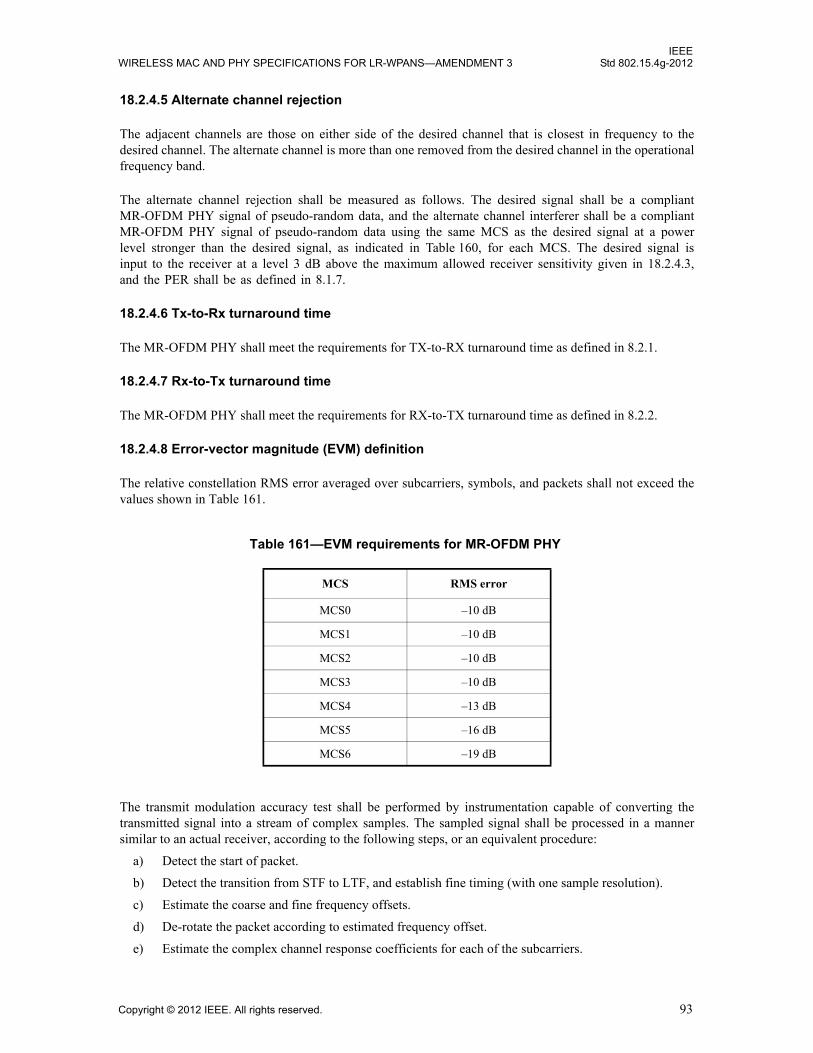
IEEEWIRELESS MAC AND PHY SPECIFICATIONS FOR LR-WPANS—AMENDMENT 3 Std 802.15.4g-2012
18.2.4.5 Alternate channel rejection
The adjacent channels are those on either side of the desired channel that is closest in frequency to thedesired channel. The alternate channel is more than one removed from the desired channel in the operationalfrequency band.
The alternate channel rejection shall be measured as follows. The desired signal shall be a compliantMR-OFDM PHY signal of pseudo-random data, and the alternate channel interferer shall be a compliantMR-OFDM PHY signal of pseudo-random data using the same MCS as the desired signal at a powerlevel stronger than the desired signal, as indicated in Table 160, for each MCS. The desired signal isinput to the receiver at a level 3 dB above the maximum allowed receiver sensitivity given in 18.2.4.3,and the PER shall be as defined in 8.1.7.
18.2.4.6 Tx-to-Rx turnaround time
The MR-OFDM PHY shall meet the requirements for TX-to-RX turnaround time as defined in 8.2.1.
18.2.4.7 Rx-to-Tx turnaround time
The MR-OFDM PHY shall meet the requirements for RX-to-TX turnaround time as defined in 8.2.2.
18.2.4.8 Error-vector magnitude (EVM) definition
The relative constellation RMS error averaged over subcarriers, symbols, and packets shall not exceed thevalues shown in Table 161.
The transmit modulation accuracy test shall be performed by instrumentation capable of converting thetransmitted signal into a stream of complex samples. The sampled signal shall be processed in a mannersimilar to an actual receiver, according to the following steps, or an equivalent procedure:
a) Detect the start of packet.
b) Detect the transition from STF to LTF, and establish fine timing (with one sample resolution).
c) Estimate the coarse and fine frequency offsets.
d) De-rotate the packet according to estimated frequency offset.
e) Estimate the complex channel response coefficients for each of the subcarriers.
Table 161—EVM requirements for MR-OFDM PHY
MCS RMS error
MCS0 –10 dB
MCS1 –10 dB
MCS2 –10 dB
MCS3 –10 dB
MCS4 –13 dB
MCS5 –16 dB
MCS6 –19 dB
Copyright © 2012 IEEE. All rights reserved. 93
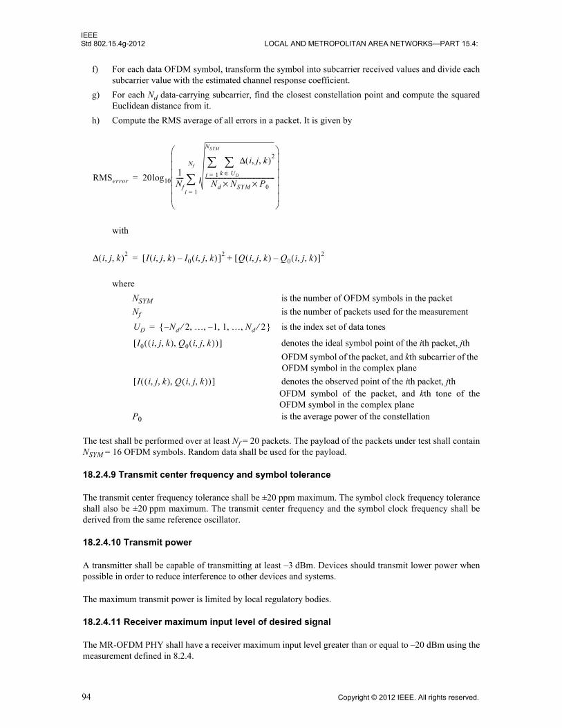
IEEEStd 802.15.4g-2012 LOCAL AND METROPOLITAN AREA NETWORKS—PART 15.4:
f) For each data OFDM symbol, transform the symbol into subcarrier received values and divide eachsubcarrier value with the estimated channel response coefficient.
g) For each Nd data-carrying subcarrier, find the closest constellation point and compute the squaredEuclidean distance from it.
h) Compute the RMS average of all errors in a packet. It is given by
with
where
NSYM is the number of OFDM symbols in the packet
Nf is the number of packets used for the measurement
is the index set of data tones
denotes the ideal symbol point of the ith packet, jth
OFDM symbol of the packet, and kth subcarrier of the OFDM symbol in the complex plane
denotes the observed point of the ith packet, jth OFDM symbol of the packet, and kth tone of theOFDM symbol in the complex plane
P0 is the average power of the constellation
The test shall be performed over at least Nf = 20 packets. The payload of the packets under test shall containNSYM = 16 OFDM symbols. Random data shall be used for the payload.
18.2.4.9 Transmit center frequency and symbol tolerance
The transmit center frequency tolerance shall be ±20 ppm maximum. The symbol clock frequency toleranceshall also be ±20 ppm maximum. The transmit center frequency and the symbol clock frequency shall bederived from the same reference oscillator.
18.2.4.10 Transmit power
A transmitter shall be capable of transmitting at least –3 dBm. Devices should transmit lower power whenpossible in order to reduce interference to other devices and systems.
The maximum transmit power is limited by local regulatory bodies.
18.2.4.11 Receiver maximum input level of desired signal
The MR-OFDM PHY shall have a receiver maximum input level greater than or equal to –20 dBm using themeasurement defined in 8.2.4.
RMSerror 20log101Nf-----
i j k, ,( )2Δk UD∈
j 1=
NSYM
Nd NSYM P0××---------------------------------------------
i 1=
Nf
=
i j k, ,( )2Δ I i j k, ,( ) I0 i j k, ,( )–[ ]2 Q i j k, ,( ) Q0 i j k, ,( )–[ ]2+=
UD Nd 2 … 1 1 … Nd, , ,–, ,⁄ 2⁄–{ }=
I0 i j k, ,( ) Q0 i j k, ,( ),( )[ ]
I i j k, ,( ) Q i j k, ,( ),( )[ ]
94 Copyright © 2012 IEEE. All rights reserved.

IEEEWIRELESS MAC AND PHY SPECIFICATIONS FOR LR-WPANS—AMENDMENT 3 Std 802.15.4g-2012
18.2.4.12 Receiver ED
The MR-OFDM PHY shall provide the receiver ED measurement as described in 8.2.5.
18.2.4.13 Link quality indicator
The MR-OFDM PHY shall provide the LQI measurement as described in 8.2.6.
18.2.4.14 Clear channel assessment (CCA)
The MR-OFDM PHY shall use one of the CCA methods as described in 8.2.7.
18.3 MR-O-QPSK PHY specification
The multi-rate and multi-regional offset quadrature phase-shift keying (MR-O-QPSK) PHY supportsmultiple PSDU data rates within each supported frequency band, as described in Table 66, employing aconcatenation of outer FEC coding, interleaving, and spreading. Selection of the data rate is specified by thevariable RateMode, as described in 18.3.2.4 and 18.3.2.5.
For all frequency bands, spreading is obtained by direct sequence spread spectrum (DSSS) applying variousspreading factors. For the 780 MHz, 915 MHz, 917 MHz, and 2450 MHz frequency bands, the MR-O-QPSK PHY may support an alternative spreading mode for the PSDU, called multiplexed direct sequencespread spectrum (MDSSS). Selection of the spreading mode is specified by the variable SpreadingMode,which is further explained in 18.3.2.4 and 18.3.2.5.
For the 780 MHz, 915 MHz, and 2450 MHz frequency bands, the MR-O-QPSK PHY supportscommunication with legacy devices according to the specifications in Clause 10, as described in 18.3.3.
An MR-O-QPSK compliant device shall support at least one of the frequency bands designated in Table 66.
An example of encoding a packet for the MR-O-QPSK PHY is given in Annex N.
18.3.1 PPDU format for MR-O-QPSK
The MR-O-QPSK PPDU shall be formatted as illustrated in Figure 140.
The synchronization header (SHR), PHY header (PHR), and PHY payload components are treated as bitstrings of length n, numbered b0 on the left and bn-1 on the right. When transmitted, they are processed b0first to bn-1 last, without regard to their content or structure.
Octets
3 Variable
Preamble SFD As defined in 18.3.1.3 PSDU
SHR PHR PHY payload
Figure 140—Format of the MR-O-QPSK PHY PPDU
Copyright © 2012 IEEE. All rights reserved. 95

IEEEStd 802.15.4g-2012 LOCAL AND METROPOLITAN AREA NETWORKS—PART 15.4:
18.3.1.1 Preamble field
The Preamble field shall contain a sequence of 56 bits, all zero, for the 780 MHz, 915 MHz, 917 MHz, and2450 MHz frequency bands. It shall contain a sequence of 32 bits, all zero, for the 470 MHz, 868 MHz,920 MHz, and 950 MHz frequency bands.
18.3.1.2 SFD
The SFD shall be the sequence described in Table 162.
18.3.1.3 PHR
The format of the PHR is shown in Figure 141. All multi-bit fields are unsigned integers and shall beprocessed MSB first.
For the 780 MHz, 915 MHz, 917 MHz, and 2450 MHz frequency bands, the Spreading Mode (SM) fieldshall be set to one if MDSSS is used for PSDU spreading (variable SpreadingMode set to MDSSS, asdescribed in 18.3.2.5). Otherwise, the SM field shall be set to zero if DSSS is used for PSDU spreading(variable SpreadingMode set to DSSS, as described in 18.3.2.4). For the 470 MHz, 868 MHz, 920 MHz, and950 MHz frequency bands, the SM field shall be set to zero (MDSSS is not supported).
The MR-O-QPSK PHY supports up to four different PSDU rate modes within each frequency band, and therate mode is given by the Rate Mode field (RM1–RM0). Table 163 shows the mapping of the bit values tothe RateMode.
The Frame Length field (L10–L0) specifies the total number of octets contained in the PSDU (prior to FECencoding).
Table 162—Format of the SFD field for the MR-O-QPSK PHY
SFD value (bits 0–15)
1 1 1 0 1 0 1 1 0 1 1 0 0 0 1 0
Bit string index 0 1 2 3 4 5–15 16–23
Bit mapping SM RM1 RM0 R1 R0 L10–L0 H7–H0
Field name Spreading Mode Rate Mode Reserved Frame Length HCS
Figure 141—Format of the PHR for MR-O-QPSK
96 Copyright © 2012 IEEE. All rights reserved.
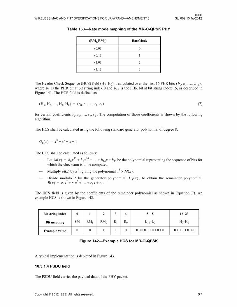
IEEEWIRELESS MAC AND PHY SPECIFICATIONS FOR LR-WPANS—AMENDMENT 3 Std 802.15.4g-2012
The Header Check Sequence (HCS) field (H7–H0) is calculated over the first 16 PHR bits ,where is the PHR bit at bit string index 0 and is the PHR bit at bit string index 15, as described inFigure 141. The HCS field is defined as
(7)
for certain coefficients . The computation of those coefficients is shown by the followingalgorithm.
The HCS shall be calculated using the following standard generator polynomial of degree 8:
The HCS shall be calculated as follows:
— Let be the polynomial representing the sequence of bits forwhich the checksum is to be computed.
— Multiply M(x) by , giving the polynomial .
— Divide modulo 2 by the generator polynomial, , to obtain the remainder polynomial,.
The HCS field is given by the coefficients of the remainder polynomial as shown in Equation (7). Anexample HCS is shown in Figure 142.
A typical implementation is depicted in Figure 143.
18.3.1.4 PSDU field
The PSDU field carries the payload data of the PHY packet.
Table 163—Rate mode mapping of the MR-O-QPSK PHY
(RM1,RM0) RateMode
(0,0) 0
(0,1) 1
(1,0) 2
(1,1) 3
Bit string index 0 1 2 3 4 5–15 16–23
Bit mapping SM RM1 RM0 R1 R0 L10–L0 H7–H0
Example value 0 0 1 0 0 0 0 0 0 0 1 0 1 0 1 0 0 1 1 1 1 0 0 0
Figure 142—Example HCS for MR-O-QPSK
b0 b1 … b15, , ,( )b0 b15
H7 H6 … H1 H0, , , ,( ) r0 r1 … r6 r7, , , ,( )=
r0 r1 … r6 r, 7, , ,
G8 x( ) x8 x2 x 1+ + +=
M x( ) b0x15 b1x14 … b14x b15+ + + +=
x8 x8 M x( )×
G8 x( )R x( ) r0x
7r1x
6 … r6x r7+ + + +=
Copyright © 2012 IEEE. All rights reserved. 97
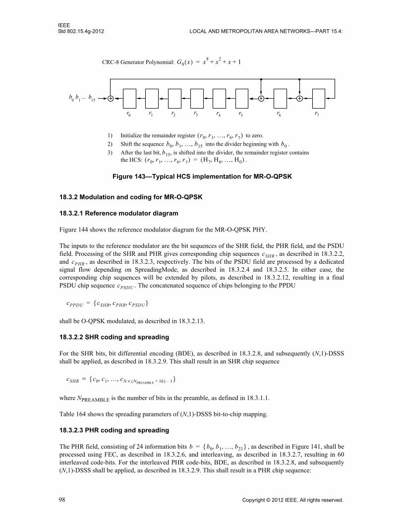
IEEEStd 802.15.4g-2012 LOCAL AND METROPOLITAN AREA NETWORKS—PART 15.4:
18.3.2 Modulation and coding for MR-O-QPSK
18.3.2.1 Reference modulator diagram
Figure 144 shows the reference modulator diagram for the MR-O-QPSK PHY.
The inputs to the reference modulator are the bit sequences of the SHR field, the PHR field, and the PSDUfield. Processing of the SHR and PHR gives corresponding chip sequences , as described in 18.3.2.2,and , as described in 18.3.2.3, respectively. The bits of the PSDU field are processed by a dedicatedsignal flow depending on SpreadingMode, as described in 18.3.2.4 and 18.3.2.5. In either case, thecorresponding chip sequences will be extended by pilots, as described in 18.3.2.12, resulting in a finalPSDU chip sequence . The concatenated sequence of chips belonging to the PPDU
shall be O-QPSK modulated, as described in 18.3.2.13.
18.3.2.2 SHR coding and spreading
For the SHR bits, bit differential encoding (BDE), as described in 18.3.2.8, and subsequently (N,1)-DSSSshall be applied, as described in 18.3.2.9. This shall result in an SHR chip sequence
where NPREAMBLE is the number of bits in the preamble, as defined in 18.3.1.1.
Table 164 shows the spreading parameters of (N,1)-DSSS bit-to-chip mapping.
18.3.2.3 PHR coding and spreading
The PHR field, consisting of 24 information bits , as described in Figure 141, shall beprocessed using FEC, as described in 18.3.2.6, and interleaving, as described in 18.3.2.7, resulting in 60interleaved code-bits. For the interleaved PHR code-bits, BDE, as described in 18.3.2.8, and subsequently(N,1)-DSSS shall be applied, as described in 18.3.2.9. This shall result in a PHR chip sequence:
7r6r1r 2r 3r 4r 5r
b0
b151
...b
0r
Figure 143—Typical HCS implementation for MR-O-QPSK
1) Initialize the remainder register to zero.
2) Shift the sequence into the divider beginning with .
3) After the last bit, , is shifted into the divider, the remainder register containsthe HCS: .
r0 r1 … r6 r, 7, , ,( )b0 b1 … b15, , , b0
b15r0 r1 … r6 r, 7, , ,( ) H7 H6 … H0, , ,( )=
CRC-8 Generator Polynomial: G8 x( ) x8
x2
x 1+ + +=
cSHRcPHR
cPSDU
cPPDU cSHR cPHR cPSDU, ,{ }=
cSHR c0 c1 … cN NPREAMBLE 16+( )× 1–, , ,{ }=
b b0 b1 … b23, , ,{ }=
98 Copyright © 2012 IEEE. All rights reserved.

IEEEWIRELESS MAC AND PHY SPECIFICATIONS FOR LR-WPANS—AMENDMENT 3 Std 802.15.4g-2012
Table 165 shows the spreading parameters of (N,1)-DSSS bit-to-chip mapping.
18.3.2.4 PSDU coding and spreading for DSSS
Figure 145 shows the signal flow when DSSS is applied to the PSDU (SpreadingMode set to DSSS).
Table 164—SHR coding and spreading parameters
Frequency band (MHz)
Chip rate (kchip/s)
BDE Spreading
470–510 100 yes (32,1)0-DSSS
779–787 1000 yes (64,1)-DSSS
868–870 100 yes (32,1)0-DSSS
902–928 1000 yes (64,1)-DSSS
917–923.5 1000 yes (64,1)-DSSS
920–928 100 yes (32,1)0/1-DSSS
950–958 100 yes (32,1)0-DSSS
2400–2483.5 2000 yes (128,1)-DSSS
Figure 144—Reference modulator diagram
FEC + Interleaving (18.3.2.6) (18.3.2.7)
BDE (18.3.2.8)
O-QPSK Modulator (18.3.2.13)(N,1) -DSSS
(18.3.2.9)
SHR bits
PHR bits
PSDU coding and spreading for DSSS
(18.3.2.4)
Concatenation
cSHR
cPHR
PSDU coding and spreading for MDSSS
(18.3.2.5)
Pilot-Insertion
(18.3.2.12)
BDE (18.3.2.8)
(N,1) -DSSS (18.3.2.9)
cPSDUPSDU bits
controlled by SpreadingMode
cPPDU
Modulated Signal
cPHR c0 c1 … cN 60× 1–, , ,{ }=
Copyright © 2012 IEEE. All rights reserved. 99

IEEEStd 802.15.4g-2012 LOCAL AND METROPOLITAN AREA NETWORKS—PART 15.4:
The supported PSDU parameters for SpreadingMode DSSS are shown in Table 166. An MR-O-QPSKcompliant device shall implement at least RateMode zero with SpreadingMode set to DSSS, as described in18.3.2.4. All other possible combinations of RateMode and SpreadingMode, as described in 18.3.2.4 and18.3.2.5, are optional.
The PSDU information bits, , with frame length of PSDU in octets(LENGTH) shall be first processed using FEC as described in 18.3.2.6, delivering a sequence of code-bits.The code-bits shall be interleaved as described in 18.3.2.7. Depending on the frequency band andRateMode, spreading by DSSS with different spreading factors shall be applied.
The first DSSS method applies BDE, as described in 18.3.2.8, to the interleaved code-bits and subsequentlythe (N,1)-bit-to-chip mapping as described in 18.3.2.9. The second DSSS method applies (N,4)-bit-to-chipmapping to the interleaved code-bits as described in 18.3.2.9. In this case, BDE shall not be applied, asdescribed in Table 166. The highest PSDU data rate is obtained by bypassing BDE and spreading, asdescribed in Figure 145 and Table 166.
Depending on the frequency band and RateMode, the output sequence of the bit-to-chip mapper shall bewhitened, as described in 18.3.2.11.
Table 165—PHR coding and spreading parameters
Frequency band (MHz)
Chip rate (kchip/s)
BDE rate ½ FEC + interleaver
Spreading
470–510 100 yes yes (8,1)0/1-DSSS
779–787 1000 yes yes (16,1)0/1-DSSS
868–870 100 yes yes (8,1)0/1-DSSS
902–928 1000 yes yes (16,1)0/1-DSSS
917–923.5 1000 yes yes (16,1)0/1-DSSS
920–928 100 yes yes (8,1)0/1-DSSS
950–958 100 yes yes (8,1)0/1-DSSS
2400–2483.5 2000 yes yes (32,1)0/1-DSSS
PSDU bits
Chip Whitening
controlled by
RateMode
controlled by
RateMode
BDE (N,1)-DSSS
(N,4)-DSSSInterleaving
FEC +
to Pilot Insertion
Figure 145—PSDU processing for DSSS
(18.3.2.6)
(18.3.2.7)
(18.3.2.8) (18.3.2.9)
(18.3.2.9) (18.3.2.11)
b b0 b1 … b8 LENGTH 1–×, , ,{ }=
100 Copyright © 2012 IEEE. All rights reserved.
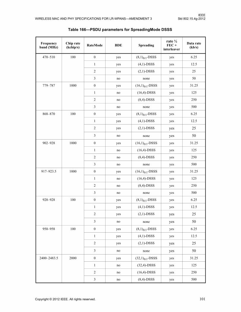
IEEEWIRELESS MAC AND PHY SPECIFICATIONS FOR LR-WPANS—AMENDMENT 3 Std 802.15.4g-2012
Table 166—PSDU parameters for SpreadingMode DSSS
Frequency band (MHz)
Chip rate (kchip/s)
RateMode BDE Spreadingrate ½ FEC +
interleaver
Data rate (kb/s)
470–510 100 0 yes (8,1)0/1-DSSS yes 6.25
1 yes (4,1)-DSSS yes 12.5
2 yes (2,1)-DSSS yes 25
3 no none yes 50
779–787 1000 0 yes (16,1)0/1-DSSS yes 31.25
1 no (16,4)-DSSS yes 125
2 no (8,4)-DSSS yes 250
3 no none yes 500
868–870 100 0 yes (8,1)0/1-DSSS yes 6.25
1 yes (4,1)-DSSS yes 12.5
2 yes (2,1)-DSSS yes 25
3 no none yes 50
902–928 1000 0 yes (16,1)0/1-DSSS yes 31.25
1 no (16,4)-DSSS yes 125
2 no (8,4)-DSSS yes 250
3 no none yes 500
917–923.5 1000 0 yes (16,1)0/1-DSSS yes 31.25
1 no (16,4)-DSSS yes 125
2 no (8,4)-DSSS yes 250
3 no none yes 500
920–928 100 0 yes (8,1)0/1-DSSS yes 6.25
1 yes (4,1)-DSSS yes 12.5
2 yes (2,1)-DSSS yes 25
3 no none yes 50
950–958 100 0 yes (8,1)0/1-DSSS yes 6.25
1 yes (4,1)-DSSS yes 12.5
2 yes (2,1)-DSSS yes 25
3 no none yes 50
2400–2483.5 2000 0 yes (32,1)0/1-DSSS yes 31.25
1 no (32,4)-DSSS yes 125
2 no (16,4)-DSSS yes 250
3 no (8,4)-DSSS yes 500
Copyright © 2012 IEEE. All rights reserved. 101

IEEEStd 802.15.4g-2012 LOCAL AND METROPOLITAN AREA NETWORKS—PART 15.4:
The relationship between the RateMode and the DataRate parameter of the MCPS-DATA.request primitiveis described in Table 46.
18.3.2.5 PSDU coding and spreading for MDSSS
Figure 146 shows the signal flow when MDSSS is applied to the PSDU (SpreadingMode set to MDSSS).
The supported PSDU parameters for SpreadingMode MDSSS are shown in Table 167. The combinations ofRateMode and SpreadingMode described in this subclause are optional.
The use of FEC depends on the rate mode chosen, as described in Table 167. When FEC is used, the PSDUinformation bits, , having a length (LENGTH) measured in octets, shall befirst processed using FEC, as described in 18.3.2.6, delivering a sequence of code-bits. When FEC isenabled, the code-bits shall be interleaved, as described in 18.3.2.7; otherwise, interleaving is bypassed. Therate mode also determines which (N,8)-MDSSS spreading factor shall be used, as described in Table 167and 18.3.2.10.
Table 167—PSDU parameters for SpreadingMode MDSSS
Frequency band (MHz)
Chip rate (kchip/s) RateMode BDE Spreading
rate ½ FEC +
interleaver
Data rate (kb/s)
470–510 not supported
779–787 1000 0 no (64,8)-MDSSS yes 62.5
1 no (32,8)-MDSSS yes 125
2 no (32,8)-MDSSS no 250
3 no (16,8)-MDSSS no 500
868–870 not supported
902–928 1000 0 no (64,8)-MDSSS yes 62.5
1 no (32,8)-MDSSS yes 125
2 no (32,8)-MDSSS no 250
3 no (16,8)-MDSSS no 500
controlled by
RateMode
PSDU bits
Interleaving
FEC +
(N,8)-MDSSS
to Pilot Insertion
Figure 146—PSDU processing for MDSSS
(18.3.2.6)
(18.3.2.7)
(18.3.2.10)
b b0 b1 … b8 LENGTH 1–×, , ,{ }=
102 Copyright © 2012 IEEE. All rights reserved.

IEEEWIRELESS MAC AND PHY SPECIFICATIONS FOR LR-WPANS—AMENDMENT 3 Std 802.15.4g-2012
The relationship between the SpreadingMode variable and the DataRate parameter of the MCPS-DATA.request primitive is described in Table 46.
18.3.2.6 Forward error correction (FEC)
Forward error correction (FEC) shall be applied to the bits of the PHR field.
For SpreadingMode set to DSSS, FEC shall be applied to the PSDU bits, as described in Table 166. ForSpreadingMode set to MDSSS, FEC is enabled depending on RateMode, as described in Table 167.
When used, FEC shall employ rate 1/2 convolutional coding with constraint length K = 7 using thefollowing generator polynomials:
The encoder is shown in Figure 147, where denotes modulo-2 addition.
917–923.5 1000 0 no (64,8)-MDSSS yes 62.5
1 no (32,8)-MDSSS yes 125
2 no (32,8)-MDSSS no 250
3 no (16,8)-MDSSS no 500
920–928 not supported
950–958 not supported
2400–2483.5 2000 0 no (128,8)-MDSSS yes 62.5
1 no (64,8)-MDSSS yes 125
2 no (64,8)-MDSSS no 250
3 no (32,8)-MDSSS no 500
Table 167—PSDU parameters for SpreadingMode MDSSS (continued)
Frequency band (MHz)
Chip rate (kchip/s)
RateMode BDE Spreadingrate ½ FEC +
interleaver
Data rate (kb/s)
G0 x( ) 1 x2
x3
x5
x6
+ + + +=
G1 x( ) 1 x x+2
x3
x6
+ + +=
⊕
uk
ka0
ka1
u u u u uk-5 uk-1 k-2 k-3 k-4 k-6
Figure 147—Convolutional encoder
Copyright © 2012 IEEE. All rights reserved. 103

IEEEStd 802.15.4g-2012 LOCAL AND METROPOLITAN AREA NETWORKS—PART 15.4:
Prior to convolutional encoding of the 24 PHR information bits , as described in18.3.1.3, the initial encoder state at k = 0 shall be set to
and the PHR information bit sequence shall be extended by a termination sequences of 6 zero bits as shownin Figure 148.
Prior to the convolutional encoding of the PSDU, the sequence of PSDU information bits, with its length (LENGTH) measured in octets, shall be extended by
appending a termination sequence of six bits, all zero, and a sequence of additional bits (pad bits) as shownin Figure 148. The pad bits shall be set to zero and the number of pad bits, , is computed from thenumber of blocks, NB, the total number of uncoded bits, ND, and the interleaver depth, NINTRLV, as follows:
(8)
(9)
The function ceiling(.) is a function that returns the smallest integer value greater than or equal to itsargument value.
The sequence of extended information bits according to Figure 148 shall be passed to the convolutionalencoder. The corresponding output sequence of code-bits, z, shall be generated as follows:
i.e., is preceding sample . The first sample, , shall be passed to the interleaver first in time, and thelast sample, , shall be passed to the interleaver last in time.
The number of code-bits referring to a single interleaving block, , is defined in 18.3.2.7.
18.3.2.7 Code-bit interleaving
Interleaving of PHR code-bits shall be employed and is separated from the interleaving of the PSDU code-bits. Since the PHR information bits are terminated, PHR code-bits and PSDU code-bits are independentcode blocks.
Interleaving of PSDU code-bits shall be employed in conjunction with PSDU FEC, in order to improverobustness against burst errors and to break correlation of consecutive bits when applying (N,4) or (N,8) bit-to-chip mapping. No PSDU code-bit interleaving shall be employed if PSDU FEC is not used, as describedin Table 167.
The sequence of PHR code-bits consists of a single sequence
PHR bits 000000 PSDU bits 000000 pad bits
Figure 148—PHR and PSDU extension prior to encoding
b b0 b1 … b23, , ,{ }=
u 1– u 2– … u 6–, , ,( ) 0 0 0 0 0 0, , , , ,( )=
b b0 b1 … b8 LENGTH 1–×, , ,{ }=
NPAD
NB ceiling((8 LENGTH× 6+ ) NINTRLV 2⁄( )⁄ )=
ND NB NINTRLV 2⁄( )×=
NPAD ND 8 LENGTH× 6+( )–=
z … ak0 ak
1 ak 1+0 ak 1+
1 ak 2+0 ak 2+
1 …, , , , ,{ } z0 z1 … z2ND 59+, , ,{ }= =
ak0 ak
1 z0z2ND 59+
NINTRLV
104 Copyright © 2012 IEEE. All rights reserved.

IEEEWIRELESS MAC AND PHY SPECIFICATIONS FOR LR-WPANS—AMENDMENT 3 Std 802.15.4g-2012
of length .
The sequence of PSDU code-bits consists of subsequences
of length , with described in Equation (8) and shown in Table 168.
In either case, the interleaver is defined by a permutation. The index of the code-bits before the permutationshall be denoted by k, where k = 0 refers to the first sample, , and refers to the lastsample, , passed to the interleaver for a given subsequence . The index i shall be the index afterthe permutation. The permutation is defined by the rule
where the degree is given in Table 168. The function floor(.) is a function that returns the largest integervalue less than or equal to its argument value.
The process of interleaving a subsequence is shown in Figure 149. The first subsequence, , shall beprocessed first in time and the last subsequence, , shall be processed last in time.
The deinterleaver, which performs the inverse relation, is defined by the rule
Table 168—Parameters of the interleaver
Degree Depth
PHR 6
PSDU 7
z0 z00 … zNINTRLV 1–
0, ,{ } z0 … z59, ,{ }= =
NINTRLV 60=
NB
zj z0j … zNINTRLV 1–
j, ,{ } z j 1–( )NINTRLV 60+ … zjNINTRLV 59+, ,{ }for j 1 … NB, ,= = =
NINTRLV NB NINTRLV
z0j
k NINTRLV 1–=zNINTRLV 1–
jz
j
iNINTRLV
λ------------------- NINTRLV 1 k––( ) mod λ( )× floor
NINTRLV 1 k––
λ------------------------------------- k+ 0 … NINTRLV, 1–,= =
λ
λ NINTRLV
10 6× 60=
7 18× 126=
z0
zNB
NINTRLV NINTRLV
FILL IN READ OUT(START)
(START)
Figure 149—Interleaver
Copyright © 2012 IEEE. All rights reserved. 105

IEEEStd 802.15.4g-2012 LOCAL AND METROPOLITAN AREA NETWORKS—PART 15.4:
18.3.2.8 Bit differential encoding (BDE)
In conjunction with (N,1)-DSSS, BDE supports noncoherent detection, which is beneficial for robustoperation at low-chip SNR.
BDE is the modulo-2 addition of a raw bit with the previous encoded bit. This is performed by thetransmitter and can be described by
where Rn is the raw bit being encoded
En is the corresponding differentially encoded bit
En–1 is the previous differentially encoded bit
BDE shall be applied to the bits of the SHR field resulting in a sequence ofdifferentially encoded bits, where NSHR is the total number of bits in the SHR, as defined in 18.3.1.1 and18.3.1.2. The initial state, , shall be zero.
BDE shall be applied to the 60 interleaved PHR code-bits, resulting in a sequence of differentially encoded bits. The initial state, , is assumed to be , assuring that duringnoncoherent differential detection, the very first interleaved PHR code-bit can be referenced to the last SHRbit.
If differential encoding is enabled, depending on the frequency band and RateMode, as described inTable 166, the sequence of differentially encoded PSDU bits shall be computed as follows. Let
be the sequence of interleaved PSDU code-bits obtained by FEC andinterleaving, with according to Equation (9). The pilot spacing ratio, M, is calculated using:
(10)
whereMP is the pilot spacing, as described in Table 182
N is the parameter of (N, 1)-DSSS, as described in Table 166
Note that M is always an integer value. Let be defined as shown:
generating a sequence of differentially encoded PSDU bits.
Referencing to zero for (n mod M) = 0 assures that, during noncoherent differential detection, the very firstinterleaved PSDU code-bit subsequent to a pilot sequence p, as described in 18.3.2.13, can be referenced tothe pilot sequence.
k λ NINTRLV 1 i––( )× NINTRLV 1–( ) floor×λ NINTRLV 1 i––( )×
NINTRLV-------------------------------------------------- i– 0 … NINTRLV 1–, ,= =
En Rn En 1–⊕=
E0SHR E1
SHR … ENSHR 1–SHR, , ,{ }
E 1–SHR
E0PHR E1
PHR … E59PHR, , ,{ }
E 1–PHR ENSHR 1–
SHR
R R0 R1 … R2ND 1–, , ,{ }=ND
MMP
N-------=
En
En
Rn En 1–⊕ n mod M( ) 0≠,
Rn 0 ⊕ n mod M( ), 0=
=
E0PSDU
E1PSDU … E2ND 1–
PSDU, , ,{ }
106 Copyright © 2012 IEEE. All rights reserved.
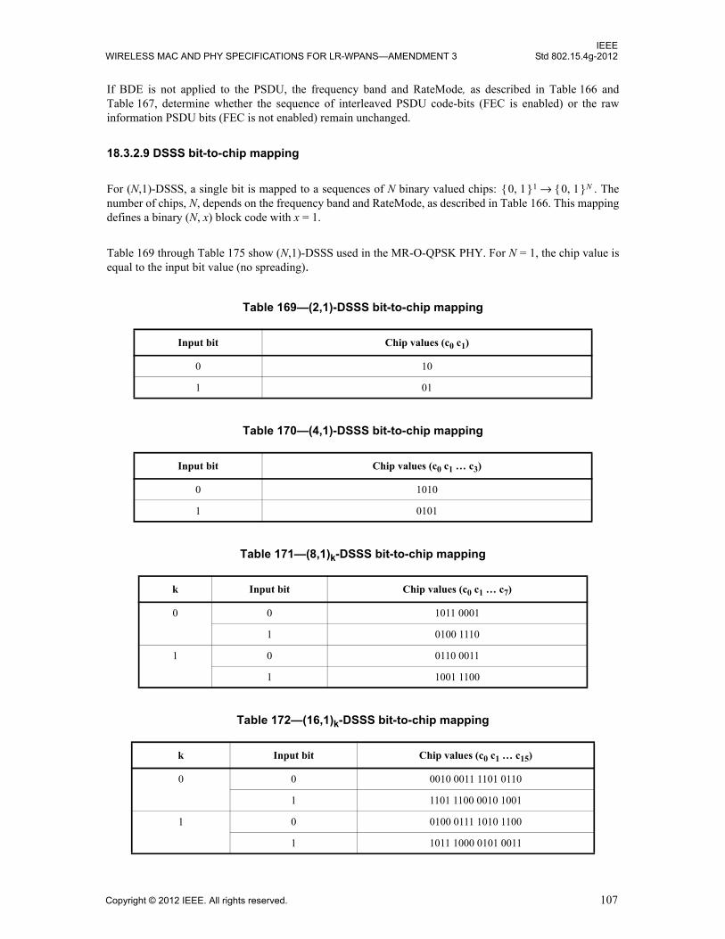
IEEEWIRELESS MAC AND PHY SPECIFICATIONS FOR LR-WPANS—AMENDMENT 3 Std 802.15.4g-2012
If BDE is not applied to the PSDU, the frequency band and RateMode, as described in Table 166 andTable 167, determine whether the sequence of interleaved PSDU code-bits (FEC is enabled) or the rawinformation PSDU bits (FEC is not enabled) remain unchanged.
18.3.2.9 DSSS bit-to-chip mapping
For (N,1)-DSSS, a single bit is mapped to a sequences of N binary valued chips: . Thenumber of chips, N, depends on the frequency band and RateMode, as described in Table 166. This mappingdefines a binary (N, x) block code with x = 1.
Table 169 through Table 175 show (N,1)-DSSS used in the MR-O-QPSK PHY. For N = 1, the chip value isequal to the input bit value (no spreading).
Table 169—(2,1)-DSSS bit-to-chip mapping
Input bit Chip values (c0 c1)
0 10
1 01
Table 170—(4,1)-DSSS bit-to-chip mapping
Input bit Chip values (c0 c1 … c3)
0 1010
1 0101
Table 171—(8,1)k-DSSS bit-to-chip mapping
k Input bit Chip values (c0 c1 … c7)
0 0 1011 0001
1 0100 1110
1 0 0110 0011
1 1001 1100
Table 172—(16,1)k-DSSS bit-to-chip mapping
k Input bit Chip values (c0 c1 … c15)
0 0 0010 0011 1101 0110
1 1101 1100 0010 1001
1 0 0100 0111 1010 1100
1 1011 1000 0101 0011
0 1,{ }1 0 1,{ }N→
Copyright © 2012 IEEE. All rights reserved. 107

IEEEStd 802.15.4g-2012 LOCAL AND METROPOLITAN AREA NETWORKS—PART 15.4:
Note that for N greater than one, (N,1)-DSSS is always preceded by differential encoding, supportingnoncoherent detection of the interleaved code-bits, as described in Table 164, Table 165, and Table 166.
For N equal to 8, 16, and 32, two spreading codes are defined, denoted as (N,1)0-DSSS and (N,1)1-DSSS.For the SHR, only (N,1)0-DSSS is applied, as described in Table 164. When applied to either the PHR or thePSDU, the two spreading codes shall be applied in an alternating manner, denoted as -DSSS, asdescribed in Table 165 and Table 166, respectively. The time variance of the spreading code improvesspectral properties while preserving a robust and simple mechanism for carrier sense7.
Table 173—(32,1)k-DSSS bit-to-chip mapping
k Input bit Chip values (c0 c1 … c31)
0 0 1101 1110 1010 0010 0111 0000 0110 0101
1 0010 0001 0101 1101 1000 1111 1001 1010
1 0 1110 1111 0101 0001 0011 1000 0011 0010
1 0001 0000 1010 1110 1100 0111 1100 1101
Table 174—(64,1)-DSSS bit-to-chip mapping
Input bit Chip values (c0 c1 … c63)
0 1011 0010 0010 0101 1011 0001 1101 0000
1101 0111 0011 1101 1111 0000 0010 1010
1 0100 1101 1101 1010 0100 1110 0010 1111
0010 1000 1100 0010 0000 1111 1101 0101
Table 175—(128,1)-DSSS bit-to-chip mapping
Input bit Chip values (c0 c1 … c127)
0 1001 1000 1000 1011 0100 1110 0100 0010
0101 0010 0110 1101 1100 0111 1010 0000
1101 0100 0110 0101 1101 1000 0111 0101
1110 0111 1101 1111 1000 0000 1010 1011
1 0110 0111 0111 0100 1011 0001 1011 1101
1010 1101 1001 0010 0011 1000 0101 1111
0010 1011 1001 1010 0010 0111 1000 1010
0001 1000 0010 0000 0111 1111 0101 0100
7When applying chip whitening according to 18.3.2.11, the spectral properties can be improved as well but carrier sense is difficult toachieve. Since the chip signal-to-noise ratio (SNR) is low for modes applying (8,1)-DSSS, (16,1)-DSSS, or (32,1)-DSSS, a mechanismfor carrier sense is beneficial for clear channel assessment (CCA). For the modes where chip whitening is applied, as described in18.3.2.11, the SNR is larger implying that CCA based on energy-detect may suffice.
N 1,( )0/1
108 Copyright © 2012 IEEE. All rights reserved.

IEEEWIRELESS MAC AND PHY SPECIFICATIONS FOR LR-WPANS—AMENDMENT 3 Std 802.15.4g-2012
In particular, let be the sequence of differentially encoded PHR bits and be the sequence of differentially encoded PSDU bits, as described in 18.3.2.8.
The even indexed bits, , shall be spread with (N,1)0-DSSS and the odd indexed bits, , shall bespread with (N,1)1-DSSS, where .
In order to exploit the capabilities of a trellis-based decoder for the outer FEC code, as described in 18.3.2.6,it is recommended to compute a soft decision value of the detected information bits.
When applying (N,4)-DSSS, a 4-tuple of bits is mapped to a sequence of N binary valued chips:. This mapping defines a binary (N, x) block code with x = 4.
Table 176, Table 177, and Table 178 show (N,4)-DSSS supported by the MR-O-QPSK PHY.
Table 176—(8,4)-DSSS bit-to-chip mapping
Input bits (b0 b1 b2 b3) Chip values (c0 c1 … c7)
0000 0000 0001
1000 1101 0000
0100 0110 1000
1100 1011 1001
0010 1110 0101
1010 0011 0100
0110 1000 1100
1110 0101 1101
0001 1010 0010
1001 0111 0011
0101 1100 1011
1101 0001 1010
0011 0100 0110
1011 1001 0111
0111 0010 1111
1111 1111 1110
Table 177—(16,4)-DSSS bit-to-chip mapping
Input bits (b0 b1 b2 b3) Chip values (c0 c1 … c15)
0000 0011 1110 0010 0101
1000 0100 1111 1000 1001
0100 0101 0011 1110 0010
1100 1001 0100 1111 1000
E0PHR E1
PHR … E59PHR, , ,{ }
E0PSDU E1
PSDU … E2ND 1–PSDU, , ,{ }
E2kX E2k 1+
X
X PHR PSDU,{ }∈
0 1,{ }4 0 1,{ }N→
Copyright © 2012 IEEE. All rights reserved. 109

IEEEStd 802.15.4g-2012 LOCAL AND METROPOLITAN AREA NETWORKS—PART 15.4:
0010 0010 0101 0011 1110
1010 1000 1001 0100 1111
0110 1110 0010 0101 0011
1110 1111 1000 1001 0100
0001 0110 1011 0111 0000
1001 0001 1010 1101 1100
0101 0000 0110 1011 0111
1101 1100 0001 1010 1101
0011 0111 0000 0110 1011
1011 1101 1100 0001 1010
0111 1011 0111 0000 0110
1111 1010 1101 1100 0001
Table 178—(32,4)-DSSS bit-to-chip mapping
Input bits (b0 b1 b2 b3) Chip values (c0 c1 … c31)
0000 1101 1001 1100 0011 0101 0010 0010 1110
1000 1110 1101 1001 1100 0011 0101 0010 0010
0100 0010 1110 1101 1001 1100 0011 0101 0010
1100 0010 0010 1110 1101 1001 1100 0011 0101
0010 0101 0010 0010 1110 1101 1001 1100 0011
1010 0011 0101 0010 0010 1110 1101 1001 1100
0110 1100 0011 0101 0010 0010 1110 1101 1001
1110 1001 1100 0011 0101 0010 0010 1110 1101
0001 1000 1100 1001 0110 0000 0111 0111 1011
1001 1011 1000 1100 1001 0110 0000 0111 0111
0101 0111 1011 1000 1100 1001 0110 0000 0111
1101 0111 0111 1011 1000 1100 1001 0110 0000
0011 0000 0111 0111 1011 1000 1100 1001 0110
1011 0110 0000 0111 0111 1011 1000 1100 1001
0111 1001 0110 0000 0111 0111 1011 1000 1100
1111 1100 1001 0110 0000 0111 0111 1011 1000
Table 177—(16,4)-DSSS bit-to-chip mapping (continued)
Input bits (b0 b1 b2 b3) Chip values (c0 c1 … c15)
110 Copyright © 2012 IEEE. All rights reserved.
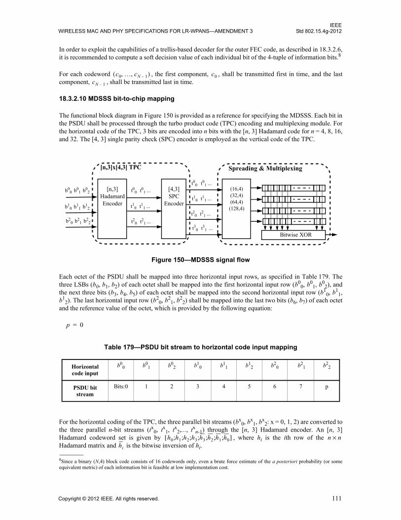
IEEEWIRELESS MAC AND PHY SPECIFICATIONS FOR LR-WPANS—AMENDMENT 3 Std 802.15.4g-2012
In order to exploit the capabilities of a trellis-based decoder for the outer FEC code, as described in 18.3.2.6,it is recommended to compute a soft decision value of each individual bit of the 4-tuple of information bits.8
For each codeword , the first component, , shall be transmitted first in time, and the lastcomponent, , shall be transmitted last in time.
18.3.2.10 MDSSS bit-to-chip mapping
The functional block diagram in Figure 150 is provided as a reference for specifying the MDSSS. Each bit inthe PSDU shall be processed through the turbo product code (TPC) encoding and multiplexing module. Forthe horizontal code of the TPC, 3 bits are encoded into n bits with the [n, 3] Hadamard code for n = 4, 8, 16,and 32. The [4, 3] single parity check (SPC) encoder is employed as the vertical code of the TPC.
Figure 150—MDSSS signal flow
Each octet of the PSDU shall be mapped into three horizontal input rows, as specified in Table 179. Thethree LSBs (b0, b1, b2) of each octet shall be mapped into the first horizontal input row (b0
0, b01, b0
2), andthe next three bits (b3, b4, b5) of each octet shall be mapped into the second horizontal input row (b1
0, b11,
b12). The last horizontal input row (b2
0, b21, b2
2) shall be mapped into the last two bits (b6, b7) of each octetand the reference value of the octet, which is provided by the following equation:
For the horizontal coding of the TPC, the three parallel bit streams (bx0, bx
1, bx2: x = 0, 1, 2) are converted to
the three parallel n-bit streams (tx0, tx1, tx2,..., txn-1) through the [n, 3] Hadamard encoder. An [n, 3]Hadamard codeword set is given by , where hi is the ith row of the Hadamard matrix and is the bitwise inversion of hi.
8Since a binary (N,4) block code consists of 16 codewords only, even a brute force estimate of the a posteriori probability (or someequivalent metric) of each information bit is feasible at low implementation cost.
Table 179—PSDU bit stream to horizontal code input mapping
Horizontal code input
b00 b0
1 b02 b1
0 b11 b1
2 b20 b2
1 b22
PSDU bit stream
Bits:0 1 2 3 4 5 6 7 p
c0 … cN 1–, ,( ) c0cN 1–
[n,3]HadamardEncoder
t30 t31 ...
t00 t01 ...
t10 t11 ...
t20 t21 ...
b00 b0
1 b02
b10 b1
1 b12
b20 b2
1 b22
[4,3]SPC
Encoder
t00 t01 ...
t10 t11 ...
t20 t21 ...
(16,4)(32,4)(64,4)(128,4)
Bitwise XOR
[n,3]x[4,3] TPC Spreading & Multiplexing
p 0=
h0 h1 h2 h3 h3 h2 h1 h0;;;;;;;[ ] n n×hi
Copyright © 2012 IEEE. All rights reserved. 111
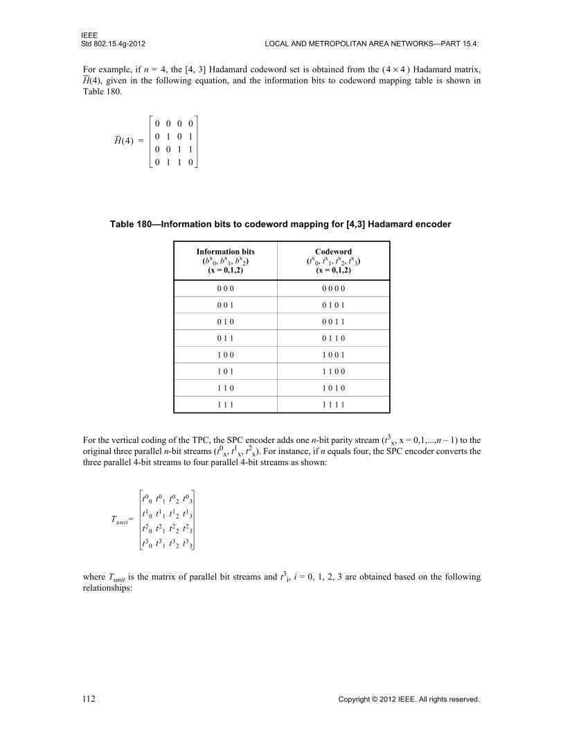
IEEEStd 802.15.4g-2012 LOCAL AND METROPOLITAN AREA NETWORKS—PART 15.4:
For example, if n = 4, the [4, 3] Hadamard codeword set is obtained from the ( ) Hadamard matrix,H(4), given in the following equation, and the information bits to codeword mapping table is shown inTable 180.
For the vertical coding of the TPC, the SPC encoder adds one n-bit parity stream (t3x, x = 0,1,...,n – 1) to theoriginal three parallel n-bit streams (t0x, t1x, t2x). For instance, if n equals four, the SPC encoder converts thethree parallel 4-bit streams to four parallel 4-bit streams as shown:
where Tunit is the matrix of parallel bit streams and t3i, i = 0, 1, 2, 3 are obtained based on the followingrelationships:
Table 180—Information bits to codeword mapping for [4,3] Hadamard encoder
Information bits(bx
0, bx1, bx
2)(x = 0,1,2)
Codeword(tx0, tx1, tx2, tx3)
(x = 0,1,2)
0 0 0 0 0 0 0
0 0 1 0 1 0 1
0 1 0 0 0 1 1
0 1 1 0 1 1 0
1 0 0 1 0 0 1
1 0 1 1 1 0 0
1 1 0 1 0 1 0
1 1 1 1 1 1 1
4 4×
H 4( )
0 0 0 0
0 1 0 1
0 0 1 1
0 1 1 0
=
Tunit
t00 t0
1 t02 t0
3
t10 t1
1 t12 t1
3
t20 t2
1 t22 t2
3
t30 t3
1 t32 t3
3
=
112 Copyright © 2012 IEEE. All rights reserved.

IEEEWIRELESS MAC AND PHY SPECIFICATIONS FOR LR-WPANS—AMENDMENT 3 Std 802.15.4g-2012
As a result of [4,3] horizontal and [4,3] vertical coding with a parity bit per octet, the PSDU bit stream istransformed into a TPC codeword matrix, forming 2-dimensional data, as shown inFigure 151.
Figure 151—Structure of turbo product codeword
For n = 8, 16, and 32, the TPC can be generated by the serial concatenations of Tunit.
Each ith row of Tunit is spread with hi; i.e., the spread ith row of Tunit is given as follows:
t30 t0
0 t10 t2
0⊕ ⊕=
t31 t0
1 t11 t2
1⊕ ⊕=
t32 t0
2 t12 t2
2⊕ ⊕=
t33 t0
3 t13 t2
3⊕ ⊕=
4 3,[ ] 4 3,[ ]× 4 4×( )
Bit 0 Bit 1 Bit 2
Bit 3 Bit 4 Bit 5
Bit 6 Bit 7 p
Hadamard Code
Od
d P
arity Ch
eck C
ode
T n 4×[ ]
Tunit n, 4=
Tunit Tunit n, 8=
Tunit Tunit Tunit Tunit n, 16=
Tunit Tunit Tunit Tunit Tunit Tunit Tunit Tunit n, 32=
=
si ti0 hi ti
1 hi ti2 hi ti
3 hi⊕⊕⊕⊕[ ] i, 0 1 2 3, , ,= =
Copyright © 2012 IEEE. All rights reserved. 113

IEEEStd 802.15.4g-2012 LOCAL AND METROPOLITAN AREA NETWORKS—PART 15.4:
Then, the vertically multiplexed bit sequence cj of length 16 can be expressed as
(11)
If n is greater than 4, the spread and multiplexed bit sequence cj of T[nx4] can also be expressed as therepeated form of Equation (11).
Then, the final output bit stream shall be bitwise XOR-ed by covering code for the chip and symbolsynchronization. For each of (16,8), (32,8), (64,8), (128,8) MDSSS, the covering code shall be bit 0 of(16,1)0-DSSS, (32,1)0-DSSS, (64,1)-DSSS, (128,1)-DSSS code, which are described in Table 172,Table 173, Table 174, and Table 175, respectively.
The final output chip sequence, c0 ~ c4n-1 (n = 4, 8, 16, 32), of (n,8) MDSSS shall be described as follows:
where mi is the covering code.
18.3.2.11 Chip whitening
When SpreadingMode is set to DSSS, the PSDU chip sequence shall be whitened, depending on thefrequency band and RateMode, as shown in Table 181. This improves spectral properties of modes with lowspreading gain or insufficient spectral properties (i.e., notches) of the spreading codes. For all other modes,no chip whitening shall be applied.
cj s0j & s1
j( ) | s2j & s3
j( )( ) 0 j 16<≤( ),=
c0 t00 & t1
0( )| t20 & t3
0( )( )=
c1 t00 & t1
0( )| t20 & t3
0( )( )=
c2 t00 & t1
0( )| t20 & t3
0( )( )=
c3 t00 & t1
0( )| t20 & t3
0( )( )=
c4 t01 & t1
1( )| t21 & t3
1( )( )=
c5 t01 & t1
1( )| t21 & t3
1( )( )=
c6 t01 & t1
1( )| t21 & t3
1( )( )=
c7 t01 & t1
1( )| t21 & t3
1( )( )=
c8 t02 & t1
2( )| t22 & t3
2( )( )=
c9 t02 & t1
2( )| t22 & t3
2( )( )=
c10 t02 & t1
2( )| t22 & t3
2( )( )=
c11 t02 & t1
2( )| t22 & t3
2( )( )=
c12 t03 & t1
3( )| t23 & t3
3( )( )=
c13 t03 & t1
3( )| t23 & t3
3( )( )=
c14 t03 & t1
3( )| t23 & t3
3( )( )=
c15 t03 & t1
3( )| t23 & t3
3( )( )=
ci ci mod 4( ) floor
in--- 4×+
mi 0 i 4n<≤( ),⊕=
114 Copyright © 2012 IEEE. All rights reserved.

IEEEWIRELESS MAC AND PHY SPECIFICATIONS FOR LR-WPANS—AMENDMENT 3 Std 802.15.4g-2012
Chip whitening is the modulo-2 addition of a chip of the PSDU at the output of the bit-to-chip mapper withthe value of a cyclic m-sequence of length for m = 9. This shall be performed by thetransmitter and is described by
whereis the raw PSDU chip being whitened
is the whitened chip
Index k starts at 0, referring to the first chip of the PSDU at the output of the bit-to-chip mapper and isincreased by one at every chip interval. Figure 152 shows the whitening process. At k = 0, the register shallbe initialized with
18.3.2.12 Pilot insertion
Periodic insertion of known chip sequences (pilots) into the stream of PSDU chips shall be used to simplifysymbol time, channel or phase tracking during receive, taking the finite coherence time of the radio channelinto account. The pilot structure of this PHY is shown in Figure 153.
Table 181—Chip Whitening for DSSS
Frequency band (MHz) RateMode
470–510 1 and 2 and 3
779–787 2 and 3
868–870 1 and 2 and 3
902–928 2 and 3
917–923.5 2 and 3
920–928 1 and 2 and 3
950–958 1 and 2 and 3
2400–2483.5 3
S k mod (2m 1 )–( ) 2m 1–
c'k ck S k mod 511( )⊕=
ck
c'k
uk 1– uk 2– … uk 9–, , ,( ) 1 0 0 0 0 0 0 0 0, , , , , , , ,( )=
uk
c k c'k
uk-5 uk-1 k-2 k-3 k-4 k-6 u u uk-7 k-8 k-9uuuu
S (k mod 511)
Figure 152—Chip whitening
Copyright © 2012 IEEE. All rights reserved. 115

IEEEStd 802.15.4g-2012 LOCAL AND METROPOLITAN AREA NETWORKS—PART 15.4:
Since the extended PSDU chip sequence always starts with a first pilot sequence, the complexity of PHRdecoding can be also reduced.
The pilot length (in number of chip samples), the pilot spacing (in number of chip samples), and thepilot sequence depend on the frequency band and are shown in Table 182.
Let
be the sequence of PSDU chips prior to pilot insertion, assuming the first PSDU chip sample, , istransmitted first in time, and the last PSDU chip sample, , is transmitted last in time. Depending onthe frame length of PSDU in octets (LENGTH), the number can be computed by
Table 182—Pilot length, spacing and chip sequences
Frequency band (MHz)
Length (# of chips)
Spacing
(# of chips)
Chip sequence
470–510 32 512 1101 1110 1010 0010 0111 0000 0110 0101
779–787 64 1024 1011 0010 0010 0101 1011 0001 1101 0000 1101 0111 0011 1101 1111 0000 0010 1010
868–870 32 512 1101 1110 1010 0010 0111 0000 0110 0101
902–928 64 1024 1011 0010 0010 0101 1011 0001 1101 0000 1101 0111 0011 1101 1111 0000 0010 1010
917–923.5 64 1024 1011 0010 0010 0101 1011 0001 1101 0000 1101 0111 0011 1101 1111 0000 0010 1010
920–928 32 512 1101 1110 1010 0010 0111 0000 0110 0101
950–958 32 512 1101 1110 1010 0010 0111 0000 0110 0101
2400–2483.5 128 2048 1001 1000 1000 1011 0100 1110 0100 0010 0101 0010 0110 1101 1100 0111 1010 0000 1101 0100 0110 0111 1101 1000 0111 0101 1110 0111 1101 1111 1000 0000 1010 1011
NP MP
pilot chip sequences
SHR PHR
SHR PHR PSDU
PSDU
Figure 153—PSDU pilot insertion
NP MPp p0 p1 … pNP 1–, , ,( )=
NP MP
p p0 p1 … pNP 1–, , ,( )=
u u0 u1 … uNPSDU 1–, , ,{ }=
u0uNPSDU 1–
NPSDU
116 Copyright © 2012 IEEE. All rights reserved.
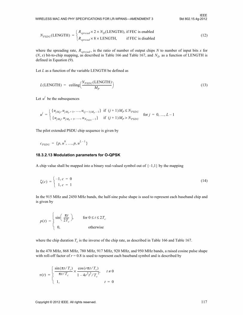
IEEEWIRELESS MAC AND PHY SPECIFICATIONS FOR LR-WPANS—AMENDMENT 3 Std 802.15.4g-2012
(12)
where the spreading rate, , is the ratio of number of output chips N to number of input bits x for(N, x) bit-to-chip mapping, as described in Table 166 and Table 167, and as a function of LENGTH isdefined in Equation (9).
Let L as a function of the variable LENGTH be defined as
(13)
Let be the subsequences
The pilot extended PSDU chip sequence is given by
18.3.2.13 Modulation parameters for O-QPSK
A chip value shall be mapped into a binary real-valued symbol out of {–1,1} by the mapping
(14)
In the 915 MHz and 2450 MHz bands, the half-sine pulse shape is used to represent each baseband chip andis given by
where the chip duration Tc is the inverse of the chip rate, as described in Table 166 and Table 167.
In the 470 MHz, 868 MHz, 780 MHz, 917 MHz, 920 MHz, and 950 MHz bands, a raised cosine pulse shapewith roll-off factor of r = 0.8 is used to represent each baseband symbol and is described by
NPSDU LENGTH( )Rspread 2 ND× LENGTH( )× if FEC is enabled ,
Rspread 8 LENGTH×× if FEC is disabled,
=
RspreadND
L LENGTH( ) ceilingNPSDU LENGTH( )
MP--------------------------------------------- =
uj
ujujMP
ujMP 1+ … u j 1+( )MP 1–, , ,{ } if j 1+( )MP NPSDU≤
ujMPujMP 1+ … uNPSDU 1–, , ,{ } if j 1+( )MP NPSDU>
for j 0 … L 1–, ,= =
cPSDU p u0 … p uL 1–, , , ,{ }=
ζ c( )1– c, 0=
1 c, 1=
=
p t( )
πt2Tc--------
for 0 t 2Tc≤ ≤,sin
0 otherwise,
=
p t( )
πt Tc⁄( )sin
πt Tc⁄---------------------------
rπt Tc⁄( )cos
1 4r2t2 Tc 2⁄–
---------------------------------× t 0≠,
1 t, 0=
=
Copyright © 2012 IEEE. All rights reserved. 117

IEEEStd 802.15.4g-2012 LOCAL AND METROPOLITAN AREA NETWORKS—PART 15.4:
Let be the discrete-time sequence of consecutive chip samples of the PPDU, wherethe first sample, , is transmitted first in time and the last sample, , is transmitted last in time. Thecontinuous-time, pulse-shaped complex baseband signal is given by:
with and according to Equation (14).
18.3.2.14 PIB attribute values for phySHRDuration, phyPHRDuration, phyPSDUDuration, and phyMaxFrameDuration9
For the MR-O-QPSK PHY, the symbol rate is defined as the bit rate of the SHR. Table 183 summarizes thesymbol rate, the symbol length, and the symbol duration for each supported frequency band.
Since for a given frequency band the number of SHR bits is constant and there is only one spreading modeapplied to the SHR, as described in 18.3.2.2, the attribute phySHRDuration (expressed in symbols) can besummarized according to Table 184. Similarly, the number of PHR code-bits is always 60 and there is afixed spreading and coding scheme for a given frequency band, as described in 18.3.2.3. The attributephyPHRDuration (expressed in symbols) is also given Table 184.
The PSDU duration depends on the PSDU length in octets (LENGTH), the variables RateMode andSpreadingMode, and the frequency band. For a given value LENGTH, the number of PSDU chip samples is
where is a function of LENGTH according to Equation (12). The value L as function of LENGTH isdefined in Equation (13), and is defined in Table 182.
9PHY PIB attributes are defined in 9.3.
Table 183—Symbol definition for MR-O-QPSK
Frequency band (MHz)
Symbol rate (ksymbol/s)
Symbol length (# of chips)
Symbol duration (μs)
470–510 3.125 32 320
779–787 15.625 64 64
868–870 3.125 32 320
902–928 15.625 64 64
917–923.5 15.625 64 64
920–928 3.125 32 320
950–958 3.125 32 320
2400–2483.5 15.625 128 64
cPPDU ck{ }0
NPPDU 1–=
c0 cNPPDU 1–
y t( ) ζ c2k( )p t 2kTc–( ) jζ c2k 1+( )p t 2k 1+( )Tc–( )+
k 0=
NPPDU 2⁄ 1–
=
j 1–= ζ
NS TS
NPSDU LENGTH( ) NPSDU LENGTH( ) L LENGTH( ) NP×+=
NPSDUNP
118 Copyright © 2012 IEEE. All rights reserved.
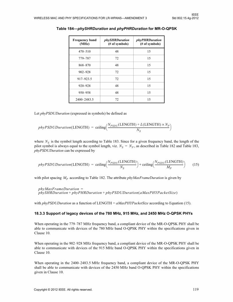
IEEEWIRELESS MAC AND PHY SPECIFICATIONS FOR LR-WPANS—AMENDMENT 3 Std 802.15.4g-2012
Let phyPSDUDuration (expressed in symbols) be defined as
where is the symbol length according to Table 183. Since for a given frequency band, the length of thepilot symbol is always equal to the symbol length, viz. , as described in Table 182 and Table 183,phyPSDUDuration can be expressed by
(15)
with pilot spacing according to Table 182. The attribute phyMaxFrameDuration is given by
with phyPSDUDuration as a function of LENGTH = aMaxPHYPacketSize according to Equation (15).
18.3.3 Support of legacy devices of the 780 MHz, 915 MHz, and 2450 MHz O-QPSK PHYs
When operating in the 779–787 MHz frequency band, a compliant device of the MR-O-QPSK PHY shall beable to communicate with devices of the 780 MHz band O-QPSK PHY within the specifications given inClause 10.
When operating in the 902–928 MHz frequency band, a compliant device of the MR-O-QPSK PHY shall beable to communicate with devices of the 915 MHz band O-QPSK PHY within the specifications given inClause 10.
When operating in the 2400–2483.5 MHz frequency band, a compliant device of the MR-O-QPSK PHYshall be able to communicate with devices of the 2450 MHz band O-QPSK PHY within the specificationsgiven in Clause 10.
Table 184—phySHRDuration and phyPHRDuration for MR-O-QPSK
Frequency band (MHz)
phySHRDuration (# of symbols)
phyPHRDuration (# of symbols)
470–510 48 15
779–787 72 15
868–870 48 15
902–928 72 15
917–923.5 72 15
920–928 48 15
950–958 48 15
2400–2483.5 72 15
phyPSDUDuration LENGTH( ) ceilingNPSDU LENGTH( ) L LENGTH( ) NP×+
NS------------------------------------------------------------------------------------------------- =
NSNS NP=
phyPSDUDuration LENGTH( ) ceilingNPSDU LENGTH( )
NS--------------------------------------------- ceiling
NPSDU LENGTH( )MP
--------------------------------------------- +=
MP
phyMaxFrameDurationphySHRDuration phyPHRDuration phyPSDUDuration aMaxPHYPacketSize( )+ +
=
Copyright © 2012 IEEE. All rights reserved. 119
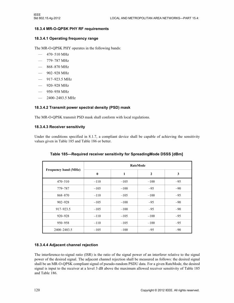
IEEEStd 802.15.4g-2012 LOCAL AND METROPOLITAN AREA NETWORKS—PART 15.4:
18.3.4 MR-O-QPSK PHY RF requirements
18.3.4.1 Operating frequency range
The MR-O-QPSK PHY operates in the following bands:
— 470–510 MHz
— 779–787 MHz
— 868–870 MHz
— 902–928 MHz
— 917–923.5 MHz
— 920–928 MHz
— 950–958 MHz
— 2400–2483.5 MHz
18.3.4.2 Transmit power spectral density (PSD) mask
The MR-O-QPSK transmit PSD mask shall conform with local regulations.
18.3.4.3 Receiver sensitivity
Under the conditions specified in 8.1.7, a compliant device shall be capable of achieving the sensitivityvalues given in Table 185 and Table 186 or better.
18.3.4.4 Adjacent channel rejection
The interference-to-signal ratio (ISR) is the ratio of the signal power of an interferer relative to the signalpower of the desired signal. The adjacent channel rejection shall be measured as follows: the desired signalshall be an MR-O-QPSK compliant signal of pseudo-random PSDU data. For a given RateMode, the desiredsignal is input to the receiver at a level 3 dB above the maximum allowed receiver sensitivity of Table 185and Table 186.
Table 185—Required receiver sensitivity for SpreadingMode DSSS [dBm]
Frequency band (MHz)RateMode
0 1 2 3
470–510 –110 –105 –100 –95
779–787 –105 –100 –95 –90
868–870 –110 –105 –100 –95
902–928 –105 –100 –95 –90
917–923.5 –105 –100 –95 –90
920–928 –110 –105 –100 –95
950–958 –110 –105 –100 –95
2400–2483.5 –105 –100 –95 –90
120 Copyright © 2012 IEEE. All rights reserved.
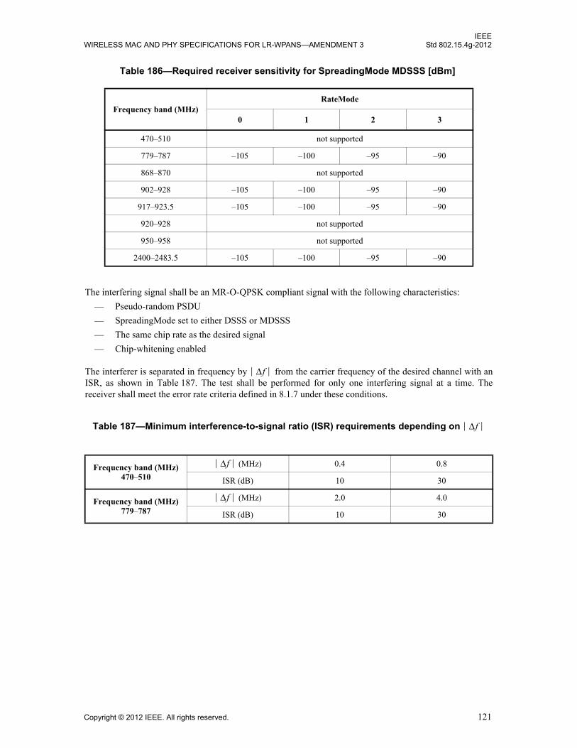
IEEEWIRELESS MAC AND PHY SPECIFICATIONS FOR LR-WPANS—AMENDMENT 3 Std 802.15.4g-2012
The interfering signal shall be an MR-O-QPSK compliant signal with the following characteristics:
— Pseudo-random PSDU
— SpreadingMode set to either DSSS or MDSSS
— The same chip rate as the desired signal
— Chip-whitening enabled
The interferer is separated in frequency by from the carrier frequency of the desired channel with anISR, as shown in Table 187. The test shall be performed for only one interfering signal at a time. Thereceiver shall meet the error rate criteria defined in 8.1.7 under these conditions.
Table 186—Required receiver sensitivity for SpreadingMode MDSSS [dBm]
Frequency band (MHz)RateMode
0 1 2 3
470–510 not supported
779–787 –105 –100 –95 –90
868–870 not supported
902–928 –105 –100 –95 –90
917–923.5 –105 –100 –95 –90
920–928 not supported
950–958 not supported
2400–2483.5 –105 –100 –95 –90
Table 187—Minimum interference-to-signal ratio (ISR) requirements depending on
Frequency band (MHz) 470–510
(MHz) 0.4 0.8
ISR (dB) 10 30
Frequency band (MHz) 779–787
(MHz) 2.0 4.0
ISR (dB) 10 30
Δf
Δf
Δf
Δf
Copyright © 2012 IEEE. All rights reserved. 121
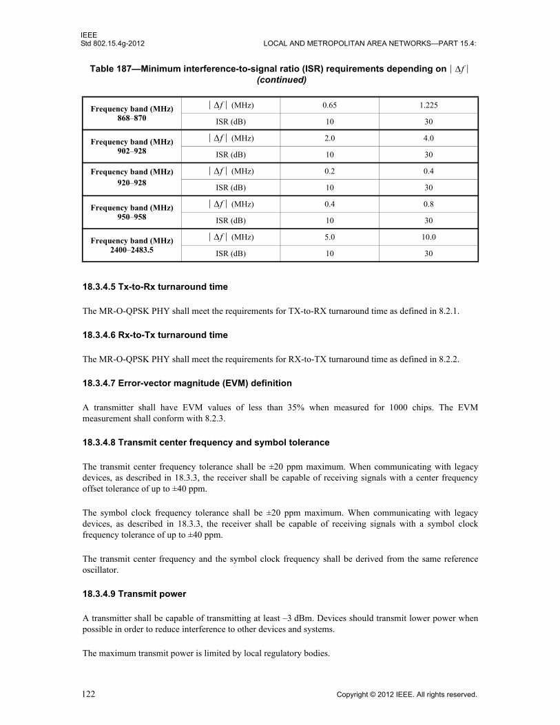
IEEEStd 802.15.4g-2012 LOCAL AND METROPOLITAN AREA NETWORKS—PART 15.4:
18.3.4.5 Tx-to-Rx turnaround time
The MR-O-QPSK PHY shall meet the requirements for TX-to-RX turnaround time as defined in 8.2.1.
18.3.4.6 Rx-to-Tx turnaround time
The MR-O-QPSK PHY shall meet the requirements for RX-to-TX turnaround time as defined in 8.2.2.
18.3.4.7 Error-vector magnitude (EVM) definition
A transmitter shall have EVM values of less than 35% when measured for 1000 chips. The EVMmeasurement shall conform with 8.2.3.
18.3.4.8 Transmit center frequency and symbol tolerance
The transmit center frequency tolerance shall be ±20 ppm maximum. When communicating with legacydevices, as described in 18.3.3, the receiver shall be capable of receiving signals with a center frequencyoffset tolerance of up to ±40 ppm.
The symbol clock frequency tolerance shall be ±20 ppm maximum. When communicating with legacydevices, as described in 18.3.3, the receiver shall be capable of receiving signals with a symbol clockfrequency tolerance of up to ±40 ppm.
The transmit center frequency and the symbol clock frequency shall be derived from the same referenceoscillator.
18.3.4.9 Transmit power
A transmitter shall be capable of transmitting at least –3 dBm. Devices should transmit lower power whenpossible in order to reduce interference to other devices and systems.
The maximum transmit power is limited by local regulatory bodies.
Frequency band (MHz) 868–870
(MHz) 0.65 1.225
ISR (dB) 10 30
Frequency band (MHz) 902–928
(MHz) 2.0 4.0
ISR (dB) 10 30
Frequency band (MHz) 920–928
(MHz) 0.2 0.4
ISR (dB) 10 30
Frequency band (MHz) 950–958
(MHz) 0.4 0.8
ISR (dB) 10 30
Frequency band (MHz) 2400–2483.5
(MHz) 5.0 10.0
ISR (dB) 10 30
Table 187—Minimum interference-to-signal ratio (ISR) requirements depending on (continued)
Δf
Δf
Δf
Δf
Δf
Δf
122 Copyright © 2012 IEEE. All rights reserved.
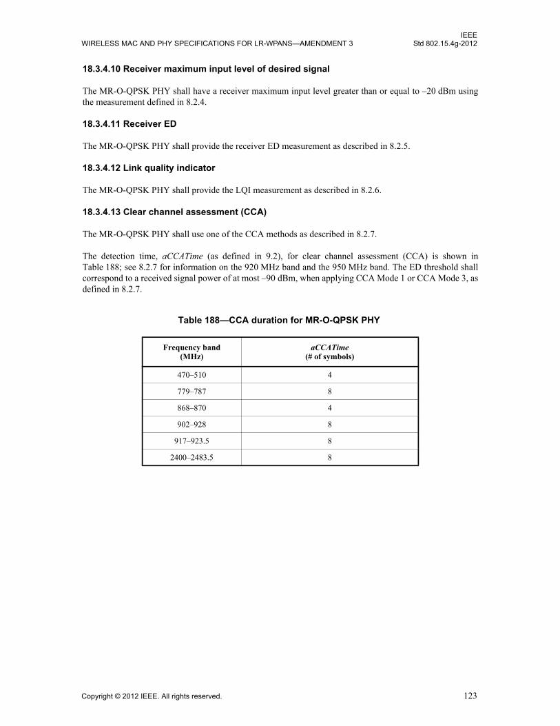
IEEEWIRELESS MAC AND PHY SPECIFICATIONS FOR LR-WPANS—AMENDMENT 3 Std 802.15.4g-2012
18.3.4.10 Receiver maximum input level of desired signal
The MR-O-QPSK PHY shall have a receiver maximum input level greater than or equal to –20 dBm usingthe measurement defined in 8.2.4.
18.3.4.11 Receiver ED
The MR-O-QPSK PHY shall provide the receiver ED measurement as described in 8.2.5.
18.3.4.12 Link quality indicator
The MR-O-QPSK PHY shall provide the LQI measurement as described in 8.2.6.
18.3.4.13 Clear channel assessment (CCA)
The MR-O-QPSK PHY shall use one of the CCA methods as described in 8.2.7.
The detection time, aCCATime (as defined in 9.2), for clear channel assessment (CCA) is shown inTable 188; see 8.2.7 for information on the 920 MHz band and the 950 MHz band. The ED threshold shallcorrespond to a received signal power of at most –90 dBm, when applying CCA Mode 1 or CCA Mode 3, asdefined in 8.2.7.
Table 188—CCA duration for MR-O-QPSK PHY
Frequency band (MHz)
aCCATime (# of symbols)
470–510 4
779–787 8
868–870 4
902–928 8
917–923.5 8
2400–2483.5 8
Copyright © 2012 IEEE. All rights reserved. 123
IEEEStd 802.15.4g-2012 LOCAL AND METROPOLITAN AREA NETWORKS—PART 15.4:
124 Copyright © 2012 IEEE. All rights reserved.
Annex A
(informative)
Bibliography
Insert the following new references at the end of the list in Annex A:
[B22] Examples of encoding a packet for the MR-FSK PHY– Part 1, Doc. IEEE 15-11-0726-07-004g, Nov. 2011.10
[B23] Examples of encoding a packet for the MR-FSK PHY– Part 2, Doc. IEEE 15-11-0759-03-004g, Nov. 2011.
10 IEEE publications are available from The Institute of Electrical and Electronics Engineers (http://standards.ieee.org/). This document is available at https://mentor.ieee.org/802.15/documents.
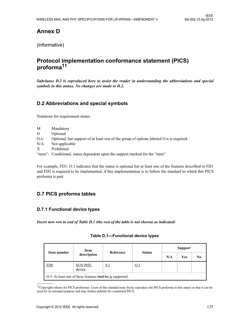
IEEEWIRELESS MAC AND PHY SPECIFICATIONS FOR LR-WPANS—AMENDMENT 3 Std 802.15.4g-2012
Annex D
(informative)
Protocol implementation conformance statement (PICS) proforma11
Subclause D.2 is reproduced here to assist the reader in understanding the abbreviations and special symbols in this annex. No changes are made to D.2.
D.2 Abbreviations and special symbols
Notations for requirement status:
M Mandatory O Optional O.n Optional, but support of at least one of the group of options labeled O.n is required. N/A Not applicable X Prohibited “item”: Conditional, status dependent upon the support marked for the “item”
For example, FD1: O.1 indicates that the status is optional but at least one of the features described in FD1 and FD2 is required to be implemented, if this implementation is to follow the standard to which this PICS proforma is part.
D.7 PICS proforma tables
D.7.1 Functional device types
Insert new row to end of Table D.1 (the rest of the table is not shown) as indicated:
11Copyright release for PICS proformas: Users of this standard may freely reproduce the PICS proforma in this annex so that it can be used for its intended purpose and may further publish the completed PICS.
Table D.1—Functional device types
Item number Item description
Reference StatusSupport
N/A Yes No
FD8 SUN PHY device
8.1 O.3
O.3: At least one of these features shall be is supported.
Copyright © 2012 IEEE. All rights reserved. 125

IEEEStd 802.15.4g-2012 LOCAL AND METROPOLITAN AREA NETWORKS—PART 15.4:
D.7.2 Major capabilities for the PHY
Insert the following new subclause (D.7.2.1a) after D.7.2.1:
D.7.2.1a PHY packet
The requirement for the PHY packet is described in Table D.2a.
D.7.2.2 Radio frequency (RF)
Insert the following new rows at the end of Table D.3 (the rest of the table is not shown):
Table D.2a—PHY packet
Item numberItem
description Reference StatusSupport
N/A Yes No
PLP1 PSDU size up to 2047 octets
9.2 FD6: M
Table D.3—Radio frequency (RF)
Item number Item description Reference StatusSupport
N/A Yes No
RF12 SUN PHYs
RF12.1 MR-FSK 18.1 FD6: M
RF12.2 MR-OFDM 18.2 FD6: O
RF12.3 MR-O-QPSK 18.3 FD6: O
RF12.4 MR-FSK Generic PHY
8.1.2.10.2 RF10.1: O
RF12.5 Transmit and receive enhanced beacons using CSM
8.1a FD1, FD6, and MLF15: M
RF12.6 At least one of the bands given in Table 66
8.1 FD6: M
RF13 SUN PHY operating modes
RF13.1 Operating mode #1 in one of the bands defined in Table 134
18.1 FD6: M
126 Copyright © 2012 IEEE. All rights reserved.
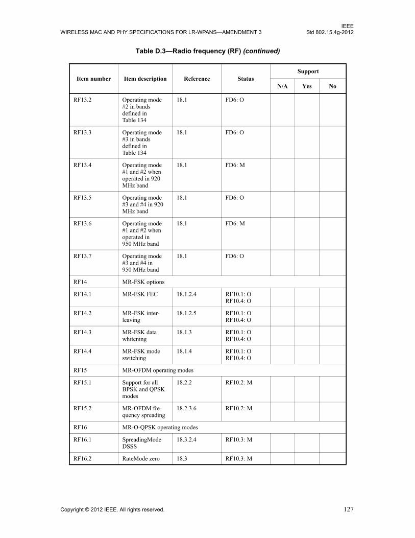
IEEEWIRELESS MAC AND PHY SPECIFICATIONS FOR LR-WPANS—AMENDMENT 3 Std 802.15.4g-2012
RF13.2 Operating mode #2 in bands defined in Table 134
18.1 FD6: O
RF13.3 Operating mode #3 in bands defined in Table 134
18.1 FD6: O
RF13.4 Operating mode #1 and #2 when operated in 920 MHz band
18.1 FD6: M
RF13.5 Operating mode #3 and #4 in 920 MHz band
18.1 FD6: O
RF13.6 Operating mode #1 and #2 when operated in 950 MHz band
18.1 FD6: M
RF13.7 Operating mode #3 and #4 in 950 MHz band
18.1 FD6: O
RF14 MR-FSK options
RF14.1 MR-FSK FEC 18.1.2.4 RF10.1: O RF10.4: O
RF14.2 MR-FSK inter-leaving
18.1.2.5 RF10.1: O RF10.4: O
RF14.3 MR-FSK data whitening
18.1.3 RF10.1: O RF10.4: O
RF14.4 MR-FSK mode switching
18.1.4 RF10.1: O RF10.4: O
RF15 MR-OFDM operating modes
RF15.1 Support for all BPSK and QPSK modes
18.2.2 RF10.2: M
RF15.2 MR-OFDM fre-quency spreading
18.2.3.6 RF10.2: M
RF16 MR-O-QPSK operating modes
RF16.1 SpreadingMode DSSS
18.3.2.4 RF10.3: M
RF16.2 RateMode zero 18.3 RF10.3: M
Table D.3—Radio frequency (RF) (continued)
Item number Item description Reference StatusSupport
N/A Yes No
Copyright © 2012 IEEE. All rights reserved. 127
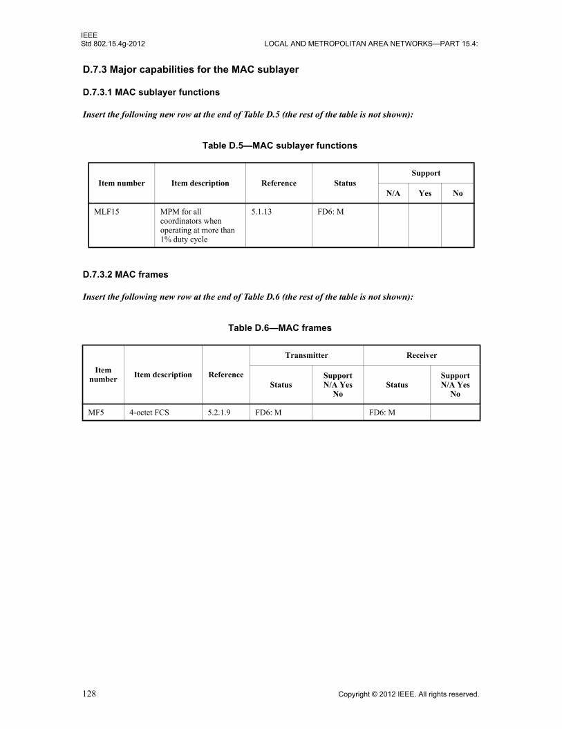
IEEEStd 802.15.4g-2012 LOCAL AND METROPOLITAN AREA NETWORKS—PART 15.4:
D.7.3 Major capabilities for the MAC sublayer
D.7.3.1 MAC sublayer functions
Insert the following new row at the end of Table D.5 (the rest of the table is not shown):
D.7.3.2 MAC frames
Insert the following new row at the end of Table D.6 (the rest of the table is not shown):
Table D.5—MAC sublayer functions
Item number Item description Reference StatusSupport
N/A Yes No
MLF15 MPM for all coordinators when operating at more than 1% duty cycle
5.1.13 FD6: M
Table D.6—MAC frames
Item number
Item description Reference
Transmitter Receiver
StatusSupportN/A Yes
NoStatus
SupportN/A Yes
No
MF5 4-octet FCS 5.2.1.9 FD6: M FD6: M
128 Copyright © 2012 IEEE. All rights reserved.

IEEEWIRELESS MAC AND PHY SPECIFICATIONS FOR LR-WPANS—AMENDMENT 3 Std 802.15.4g-2012
Insert after Annex J the following new annex (Annex K):
Annex K
(informative)
Example usage of MR-FSK Generic PHY mechanism
K.1 Introduction
In addition to the standard-defined PHY modes specified in Table 134 and Table 135, as described in 18.1.2,an MR-FSK-compliant device may also support other modes derived using the MR-FSK Generic PHY descriptor. The MR-FSK Generic PHY descriptor provides the complete set of parameters necessary to define a FSK PHY mode, such as modulation type, symbol rate, modulation order, and modulation index for FSK operation, as described in Table 71a.
The PIB attribute phyNumSUNPageEntriesSupported contains the number of SUN operating modes supported by a device, and each supported mode is included in a table entry in the PIB attribute phySUNPageEntriesSupported. In addition, the PIB attribute phyCurrentSUNPageEntry specifies the current PHY mode of operation if phyCurrentPage equals seven or eight.
K.2 Example of SUN channel page usage for a device supporting MR-FSK Generic PHY modes
Table K.1 shows an example of a device supporting three MR-FSK Generic PHY modes. Each of the three MR-FSK Generic PHY descriptors is shown in Table K.1.
Table K.1—Example of MR-FSK Generic PHY descriptors for a device operating in the 915 MHz band
Name PHY operating mode 0 PHY operating mode 1 PHY operating mode 2
GenericPHYID 0 1 2
FirstChannelFrequency 902.25 MHz 902.3 MHz 902.4 MHz
NumberOfChannels 52 85 64
ChannelSpacing 500 kHz 300 kHz 400 kHz
SymbolRate 76.8 ksymbol/s 100 ksymbol/s 142.222 ksymbol/s
ModulationScheme FSK FSK FSK
FSKModulationOrder 2-level 2-level 2-level
FSKModulationIndex 1.0 0.5 1.0
FSKBT n/a n/a n/a
Copyright © 2012 IEEE. All rights reserved. 129

IEEEStd 802.15.4g-2012 LOCAL AND METROPOLITAN AREA NETWORKS—PART 15.4:
K.3 Example of SUN channel page usage for a device supporting both stan-dard-defined and MR-FSK Generic PHY modes
The example device supports three standard-defined PHY modes and one MR-FSK Generic PHY mode.The standard-defined PHY modes used in this example are the MR-FSK PHY mode for the 915 MHz band,the MR-FSK PHY mode for the 950 MHz band, and the MR-O-QPSK (DSSS) PHY mode for the 915 MHzband. If the current operating mode of the device is 915 MHz filtered FSK with a data rate of 200 kb/s, thedevice would have the following values for the PIB attributes:
— phySUNNumGenericPHYDescriptors = 1— phyNumSUNPageEntriesSupported = 4— phySUNPageEntriesSupported, as shown in Figure K.1— phyCurrentSUNPageEntry, as shown in Figure K.2— phyMaxSUNChannelSupported = 63— phySUNChannelsSupported = the list of the channel numbers supported— phyCurrentChannel = a unique value between 0 and phyMaxSUNChannelSupported— phyCurrentPage = 7
Entry Channel page
Frequency band
Modulation scheme PHY mode
1 Page 9 915 MHz Filtered FSK Operating modes 1 and 3 supported
2 Page 9 950 MHz Filtered FSK Operating modes 1,2, and 3 supported
3 Page 10 915 MHz O-QPSK All four standard-defined modes supported
4 Page 10 reserved reserved One Generic PHY mode supported
Figure K.1—SUN page entries supported
Page 7 915 MHz Filtered FSK Operating mode 3 (200 kb/s) supported
Figure K.2—Current SUN page entry
130 Copyright © 2012 IEEE. All rights reserved.
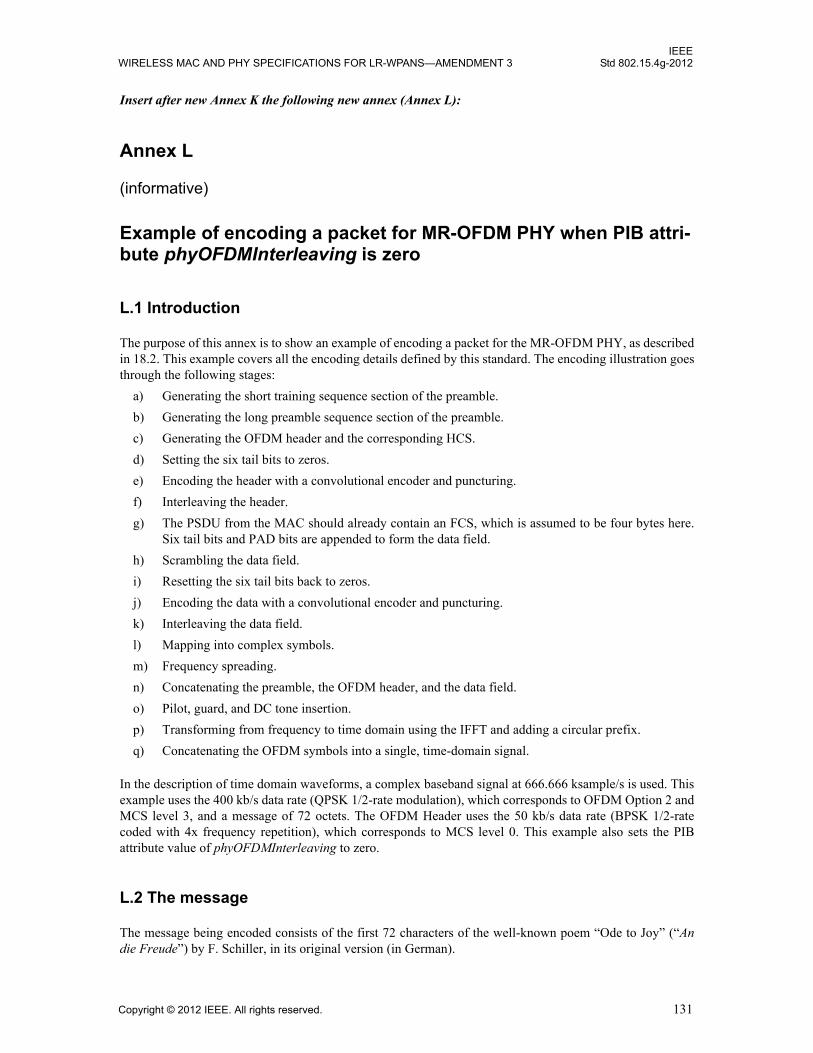
IEEEWIRELESS MAC AND PHY SPECIFICATIONS FOR LR-WPANS—AMENDMENT 3 Std 802.15.4g-2012
Insert after new Annex K the following new annex (Annex L):
Annex L
(informative)
Example of encoding a packet for MR-OFDM PHY when PIB attri-bute phyOFDMInterleaving is zero
L.1 Introduction
The purpose of this annex is to show an example of encoding a packet for the MR-OFDM PHY, as described in 18.2. This example covers all the encoding details defined by this standard. The encoding illustration goes through the following stages:
a) Generating the short training sequence section of the preamble.
b) Generating the long preamble sequence section of the preamble.
c) Generating the OFDM header and the corresponding HCS.
d) Setting the six tail bits to zeros.
e) Encoding the header with a convolutional encoder and puncturing.
f) Interleaving the header.
g) The PSDU from the MAC should already contain an FCS, which is assumed to be four bytes here. Six tail bits and PAD bits are appended to form the data field.
h) Scrambling the data field.
i) Resetting the six tail bits back to zeros.
j) Encoding the data with a convolutional encoder and puncturing.
k) Interleaving the data field.
l) Mapping into complex symbols.
m) Frequency spreading.
n) Concatenating the preamble, the OFDM header, and the data field.
o) Pilot, guard, and DC tone insertion.
p) Transforming from frequency to time domain using the IFFT and adding a circular prefix.
q) Concatenating the OFDM symbols into a single, time-domain signal.
In the description of time domain waveforms, a complex baseband signal at 666.666 ksample/s is used. This example uses the 400 kb/s data rate (QPSK 1/2-rate modulation), which corresponds to OFDM Option 2 and MCS level 3, and a message of 72 octets. The OFDM Header uses the 50 kb/s data rate (BPSK 1/2-rate coded with 4x frequency repetition), which corresponds to MCS level 0. This example also sets the PIB attribute value of phyOFDMInterleaving to zero.
L.2 The message
The message being encoded consists of the first 72 characters of the well-known poem “Ode to Joy” (“An die Freude”) by F. Schiller, in its original version (in German).
Copyright © 2012 IEEE. All rights reserved. 131

IEEEStd 802.15.4g-2012 LOCAL AND METROPOLITAN AREA NETWORKS—PART 15.4:
Freude, schöner Götterfunken,
Tochter aus Elysium,
Wir betreten feuertrunken,
Himmlische dein Heiligtum.
The message is converted to ASCII and a CRC32 is added, as defined in 5.2.1.9.
Note that the MAC header will not be included. It is assumed to be part of the message in this annex.
The resulting 76 octet PSDU is shown in Table L.1.
Table L.1—The message a
aTo extract the bit stream from this table, the octet is read LSB first.
Octet # Value (Hex) Octet # Value
(Hex) Octet # Value (Hex) Octet # Value
(Hex)
1 46 21 65 41 73 61 74
2 72 22 72 42 20 62 65
3 65 23 66 43 45 63 6E
4 75 24 75 44 6C 64 20
5 64 25 6E 45 79 65 66
6 65 26 6B 46 73 66 65
7 2C 27 65 47 69 67 75
8 20 28 6E 48 75 68 65
9 73 29 2C 49 6D 69 72
10 63 30 A 50 2C 70 74
11 68 31 54 51 A 71 72
12 F6 32 6F 52 57 72 75
13 6E 33 63 53 69 73 33
14 65 34 68 54 72 74 3C
15 72 35 74 55 20 75 69
16 20 36 65 56 62 76 7C
17 47 37 72 57 65 — —
18 F6 38 20 58 74 — —
19 74 39 61 59 72 — —
20 74 40 75 60 65 — —
132 Copyright © 2012 IEEE. All rights reserved.

IEEEWIRELESS MAC AND PHY SPECIFICATIONS FOR LR-WPANS—AMENDMENT 3 Std 802.15.4g-2012
L.3 Generation of the OFDM header
L.3.1 HCS and PAD bits insertion
In this example, the payload data has a size of 76 octets, and it will be encoded using QPSK modulation, 1/2-rate coding (Rate field value = 3). The scrambler index will be the first one (Scrambler ID = 0).
The corresponding OFDM header, including the HCS, is represented in Table L.2.
In this configuration, no extra PAD bit is necessary. The size of the header will fill up exactly six OFDM symbols.
L.3.2 Convolutional encoding
After convolutional encoding of the OFDM header, the size is now doubled and the corresponding bits are represented in Table L.3. No puncturing is applied in this configuration.
Table L.2—OFDM Header
Field Name Bit # Bit Value Field Name Bit # Bit Value
Rate
1 0Scrambler
20 0
2 0 21 0
3 0 RFU 22 0
4 1
HCS
23 1
5 1 24 1
RFU 6 0 25 1
Length
7 0 26 1
8 0 27 1
9 0 28 1
10 0 29 0
11 1 30 1
12 0
Tail
31 0
13 0 32 0
14 1 33 0
15 1 34 0
16 0 35 0
17 0 36 0
RFU 18 0 — —
19 0 — —
Copyright © 2012 IEEE. All rights reserved. 133

IEEEStd 802.15.4g-2012 LOCAL AND METROPOLITAN AREA NETWORKS—PART 15.4:
L.3.3 Interleaving
A two-step interleaver is applied to the data, as defined in 18.2.3.5. The resulting data is represented in Table L.4.
Table L.3—OFDM Header after convolutional encoding
Bit # Bit Value Bit # Bit Value Bit # Bit Value Bit # Bit Value
1 0 19 0 37 1 55 0
2 0 20 1 38 0 56 0
3 0 21 0 39 0 57 0
4 0 22 0 40 1 58 0
5 0 23 0 41 1 59 1
6 0 24 1 42 1 60 0
7 1 25 1 43 0 61 1
8 1 26 1 44 0 62 1
9 1 27 0 45 1 63 1
10 0 28 0 46 1 64 0
11 1 29 1 47 1 65 1
12 0 30 0 48 0 66 0
13 0 31 0 49 0 67 1
14 0 32 0 50 1 68 1
15 1 33 1 51 1 69 1
16 1 34 1 52 0 70 0
17 1 35 1 53 1 71 1
18 0 36 1 54 0 72 1
Table L.4—OFDM Header after interleaving
Bit # Bit Value Bit # Bit Value Bit # Bit Value Bit # Bit Value
1 0 19 1 37 1 55 0
2 0 20 0 38 1 56 1
3 1 21 1 39 0 57 1
4 0 22 0 40 1 58 0
5 0 23 0 41 0 59 0
6 0 24 1 42 1 60 0
7 1 25 1 43 0 61 1
134 Copyright © 2012 IEEE. All rights reserved.

IEEEWIRELESS MAC AND PHY SPECIFICATIONS FOR LR-WPANS—AMENDMENT 3 Std 802.15.4g-2012
L.3.4 Bit mapping
The 72 bits are split into six OFDM symbols. The bit mapping for the OFDM header in this example is BPSK. Therefore, Q is always zero. The I value is mapped as defined in Table L.5.
8 1 26 0 44 1 62 0
9 0 27 0 45 0 63 1
10 0 28 1 46 1 64 0
11 1 29 1 47 1 65 1
12 0 30 1 48 0 66 1
13 0 31 0 49 0 67 1
14 1 32 1 50 0 68 1
15 0 33 0 51 0 69 1
16 0 34 0 52 0 70 0
17 0 35 1 53 1 71 1
18 1 36 1 54 1 72 1
Table L.5—Bit mapping for the OFDM Header
Symbol 1 Symbol 2 Symbol 3 Symbol 4 Symbol 5 Symbol 6
I Q I Q I Q I Q I Q I Q
1 –1 0 –1 0 1 0 1 0 –1 0 1 0
2 –1 0 1 0 –1 0 1 0 –1 0 –1 0
3 1 0 –1 0 –1 0 –1 0 –1 0 1 0
4 –1 0 –1 0 1 0 1 0 –1 0 –1 0
5 –1 0 –1 0 1 0 –1 0 1 0 1 0
6 –1 0 1 0 1 0 1 0 1 0 1 0
7 1 0 1 0 –1 0 –1 0 –1 0 1 0
8 1 0 –1 0 1 0 1 0 1 0 1 0
9 –1 0 1 0 –1 0 –1 0 1 0 1 0
10 –1 0 –1 0 –1 0 1 0 –1 0 –1 0
11 1 0 –1 0 1 0 1 0 –1 0 1 0
12 –1 0 1 0 1 0 –1 0 –1 0 1 0
Table L.4—OFDM Header after interleaving (continued)
Bit # Bit Value Bit # Bit Value Bit # Bit Value Bit # Bit Value
Copyright © 2012 IEEE. All rights reserved. 135

IEEEStd 802.15.4g-2012 LOCAL AND METROPOLITAN AREA NETWORKS—PART 15.4:
L.3.5 Frequency spreading
In this example, a frequency spreading of four is applied to the OFDM header. The original 12 bits in each symbol (Bin # 25 through 36 in Table L.6) are duplicated within the same symbol. The resulting symbols have 48 data bits each. The duplicated bits have a phase rotation, as defined in 18.2.3.6.
Table L.6—OFDM Header in the frequency domain
Symbol 1 Symbol 2 Symbol 3 Symbol 4 Symbol 5 Symbol 6
I Q I Q I Q I Q I Q I Q
1 0 –1 0 –1 0 1 0 1 0 –1 0 1
2 0 1 0 –1 0 1 0 –1 0 1 0 1
3 0 1 0 –1 0 –1 0 –1 0 –1 0 1
4 0 1 0 1 0 –1 0 –1 0 1 0 1
5 0 –1 0 –1 0 1 0 –1 0 1 0 1
6 0 1 0 –1 0 –1 0 –1 0 –1 0 –1
7 0 1 0 1 0 –1 0 –1 0 –1 0 1
8 0 –1 0 1 0 –1 0 –1 0 –1 0 –1
9 0 –1 0 1 0 –1 0 –1 0 1 0 1
10 0 1 0 1 0 1 0 –1 0 1 0 1
11 0 1 0 –1 0 1 0 1 0 –1 0 1
12 0 1 0 –1 0 –1 0 1 0 1 0 –1
13 1 0 1 0 –1 0 –1 0 1 0 –1 0
14 0 –1 0 1 0 –1 0 1 0 –1 0 –1
15 1 0 –1 0 –1 0 –1 0 –1 0 1 0
16 0 1 0 1 0 –1 0 –1 0 1 0 1
17 1 0 1 0 –1 0 1 0 –1 0 –1 0
18 0 –1 0 1 0 1 0 1 0 1 0 1
19 1 0 1 0 –1 0 –1 0 –1 0 1 0
20 0 –1 0 1 0 –1 0 –1 0 –1 0 –1
21 1 0 –1 0 1 0 1 0 –1 0 –1 0
22 0 –1 0 –1 0 –1 0 1 0 –1 0 –1
23 1 0 –1 0 1 0 1 0 –1 0 1 0
24 0 1 0 –1 0 –1 0 1 0 1 0 –1
25 –1 0 –1 0 1 0 1 0 –1 0 1 0
26 –1 0 1 0 –1 0 1 0 –1 0 –1 0
27 1 0 –1 0 –1 0 –1 0 –1 0 1 0
136 Copyright © 2012 IEEE. All rights reserved.
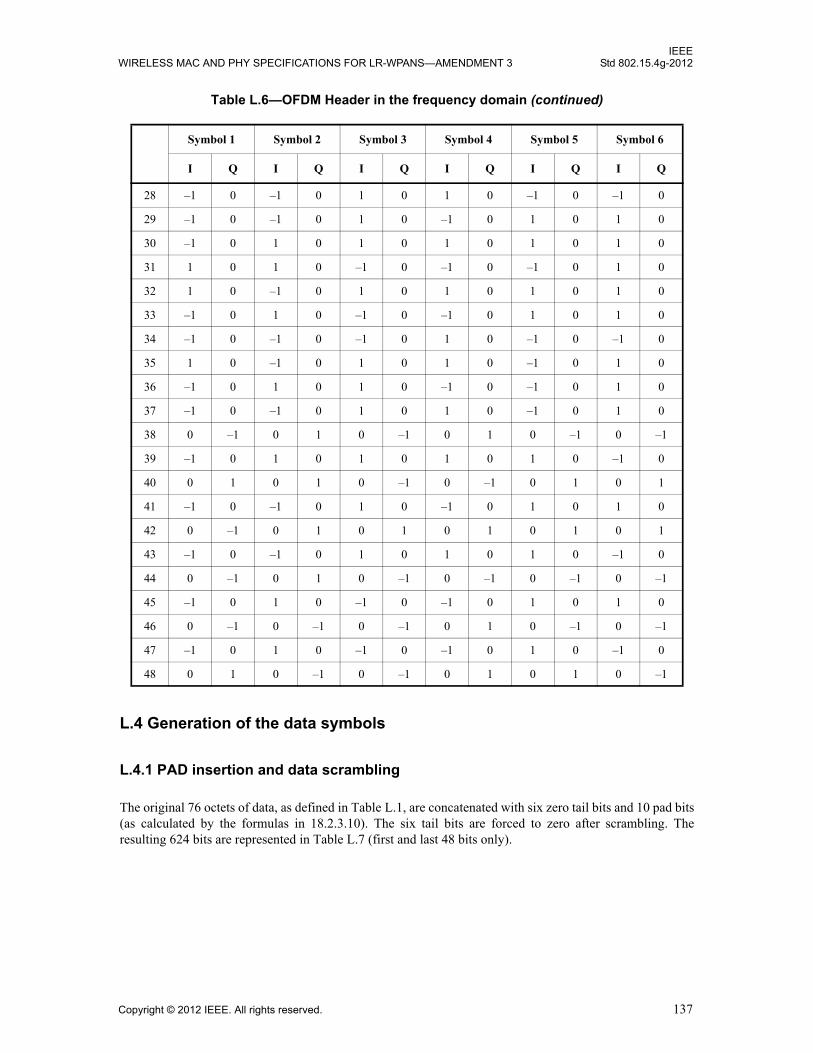
IEEEWIRELESS MAC AND PHY SPECIFICATIONS FOR LR-WPANS—AMENDMENT 3 Std 802.15.4g-2012
L.4 Generation of the data symbols
L.4.1 PAD insertion and data scrambling
The original 76 octets of data, as defined in Table L.1, are concatenated with six zero tail bits and 10 pad bits (as calculated by the formulas in 18.2.3.10). The six tail bits are forced to zero after scrambling. The resulting 624 bits are represented in Table L.7 (first and last 48 bits only).
28 –1 0 –1 0 1 0 1 0 –1 0 –1 0
29 –1 0 –1 0 1 0 –1 0 1 0 1 0
30 –1 0 1 0 1 0 1 0 1 0 1 0
31 1 0 1 0 –1 0 –1 0 –1 0 1 0
32 1 0 –1 0 1 0 1 0 1 0 1 0
33 –1 0 1 0 –1 0 –1 0 1 0 1 0
34 –1 0 –1 0 –1 0 1 0 –1 0 –1 0
35 1 0 –1 0 1 0 1 0 –1 0 1 0
36 –1 0 1 0 1 0 –1 0 –1 0 1 0
37 –1 0 –1 0 1 0 1 0 –1 0 1 0
38 0 –1 0 1 0 –1 0 1 0 –1 0 –1
39 –1 0 1 0 1 0 1 0 1 0 –1 0
40 0 1 0 1 0 –1 0 –1 0 1 0 1
41 –1 0 –1 0 1 0 –1 0 1 0 1 0
42 0 –1 0 1 0 1 0 1 0 1 0 1
43 –1 0 –1 0 1 0 1 0 1 0 –1 0
44 0 –1 0 1 0 –1 0 –1 0 –1 0 –1
45 –1 0 1 0 –1 0 –1 0 1 0 1 0
46 0 –1 0 –1 0 –1 0 1 0 –1 0 –1
47 –1 0 1 0 –1 0 –1 0 1 0 –1 0
48 0 1 0 –1 0 –1 0 1 0 1 0 –1
Table L.6—OFDM Header in the frequency domain (continued)
Symbol 1 Symbol 2 Symbol 3 Symbol 4 Symbol 5 Symbol 6
I Q I Q I Q I Q I Q I Q
Copyright © 2012 IEEE. All rights reserved. 137

IEEEStd 802.15.4g-2012 LOCAL AND METROPOLITAN AREA NETWORKS—PART 15.4:
L.4.2 Convolutional encoding and puncturing
After convolutional encoding of the payload, the size is now doubled and the corresponding bits are represented in Table L.8. No puncturing is applied in this configuration.
L.4.3 Interleaving
A two-step interleaver is applied to the data, as defined in 18.2.3.5. The resulting data (first and last 48 bits only) is represented in Table L.9.
Table L.7—First and last 48 bits after pad insertion and scrambling
Bit # Bit Value Bit # Bit Value Bit # Bit Value Bit # Bit Value
1 1 25 0 577 0 601 1
2 0 26 0 578 0 602 0
3 0 27 0 579 1 603 0
4 0 28 0 580 0 604 0
5 0 29 0 581 0 605 0
6 1 30 0 582 1 606 0
7 0 31 0 583 1 607 0
8 0 32 1 584 0 608 0
9 0 33 0 585 0 609 0
10 1 34 0 586 1 610 0
11 0 35 0 587 1 611 0
12 1 36 0 588 0 612 0
13 1 37 0 589 1 613 0
14 1 38 0 590 1 614 0
15 0 39 1 591 0 615 0
16 0 40 1 592 0 616 0
17 1 41 0 593 1 617 0
18 0 42 1 594 0 618 0
19 0 43 1 595 1 619 0
20 0 44 0 596 1 620 1
21 1 45 1 597 1 621 1
22 1 46 0 598 1 622 0
23 0 47 0 599 0 623 1
24 1 48 0 600 0 624 1
138 Copyright © 2012 IEEE. All rights reserved.
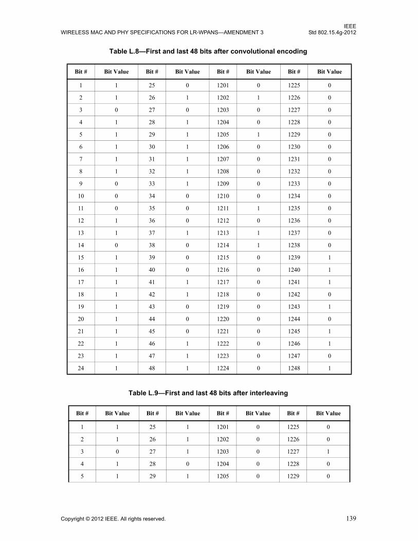
IEEEWIRELESS MAC AND PHY SPECIFICATIONS FOR LR-WPANS—AMENDMENT 3 Std 802.15.4g-2012
Table L.8—First and last 48 bits after convolutional encoding
Bit # Bit Value Bit # Bit Value Bit # Bit Value Bit # Bit Value
1 1 25 0 1201 0 1225 0
2 1 26 1 1202 1 1226 0
3 0 27 0 1203 0 1227 0
4 1 28 1 1204 0 1228 0
5 1 29 1 1205 1 1229 0
6 1 30 1 1206 0 1230 0
7 1 31 1 1207 0 1231 0
8 1 32 1 1208 0 1232 0
9 0 33 1 1209 0 1233 0
10 0 34 0 1210 0 1234 0
11 0 35 0 1211 1 1235 0
12 1 36 0 1212 0 1236 0
13 1 37 1 1213 1 1237 0
14 0 38 0 1214 1 1238 0
15 1 39 0 1215 0 1239 1
16 1 40 0 1216 0 1240 1
17 1 41 1 1217 0 1241 1
18 1 42 1 1218 0 1242 0
19 1 43 0 1219 0 1243 1
20 1 44 0 1220 0 1244 0
21 1 45 0 1221 0 1245 1
22 1 46 1 1222 0 1246 1
23 1 47 1 1223 0 1247 0
24 1 48 1 1224 0 1248 1
Table L.9—First and last 48 bits after interleaving
Bit # Bit Value Bit # Bit Value Bit # Bit Value Bit # Bit Value
1 1 25 1 1201 0 1225 0
2 1 26 1 1202 0 1226 0
3 0 27 1 1203 0 1227 1
4 1 28 0 1204 0 1228 0
5 1 29 1 1205 0 1229 0
Copyright © 2012 IEEE. All rights reserved. 139
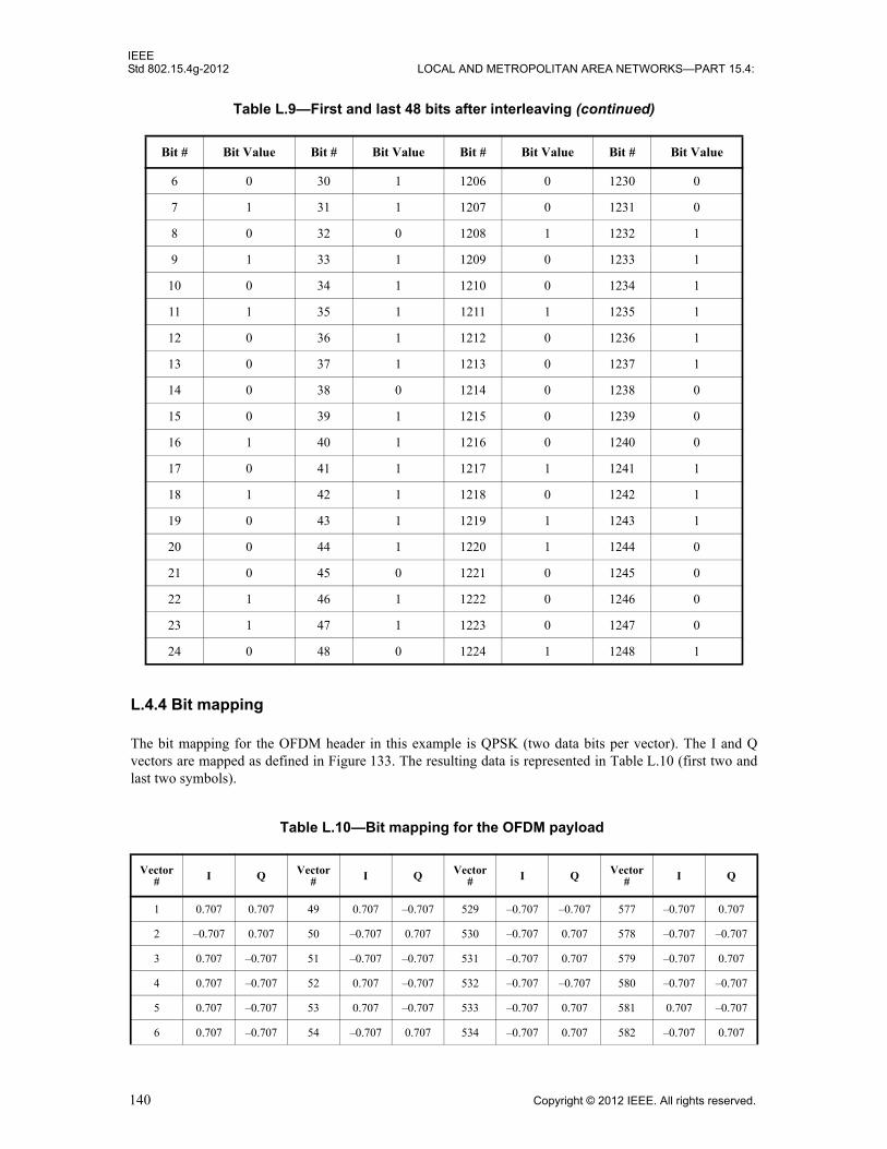
IEEEStd 802.15.4g-2012 LOCAL AND METROPOLITAN AREA NETWORKS—PART 15.4:
L.4.4 Bit mapping
The bit mapping for the OFDM header in this example is QPSK (two data bits per vector). The I and Q vectors are mapped as defined in Figure 133. The resulting data is represented in Table L.10 (first two and last two symbols).
6 0 30 1 1206 0 1230 0
7 1 31 1 1207 0 1231 0
8 0 32 0 1208 1 1232 1
9 1 33 1 1209 0 1233 1
10 0 34 1 1210 0 1234 1
11 1 35 1 1211 1 1235 1
12 0 36 1 1212 0 1236 1
13 0 37 1 1213 0 1237 1
14 0 38 0 1214 0 1238 0
15 0 39 1 1215 0 1239 0
16 1 40 1 1216 0 1240 0
17 0 41 1 1217 1 1241 1
18 1 42 1 1218 0 1242 1
19 0 43 1 1219 1 1243 1
20 0 44 1 1220 1 1244 0
21 0 45 0 1221 0 1245 0
22 1 46 1 1222 0 1246 0
23 1 47 1 1223 0 1247 0
24 0 48 0 1224 1 1248 1
Table L.10—Bit mapping for the OFDM payload
Vector# I Q Vector
# I Q Vector# I Q Vector
# I Q
1 0.707 0.707 49 0.707 –0.707 529 –0.707 –0.707 577 –0.707 0.707
2 –0.707 0.707 50 –0.707 0.707 530 –0.707 0.707 578 –0.707 –0.707
3 0.707 –0.707 51 –0.707 –0.707 531 –0.707 0.707 579 –0.707 0.707
4 0.707 –0.707 52 0.707 –0.707 532 –0.707 –0.707 580 –0.707 –0.707
5 0.707 –0.707 53 0.707 –0.707 533 –0.707 0.707 581 0.707 –0.707
6 0.707 –0.707 54 –0.707 0.707 534 –0.707 0.707 582 –0.707 0.707
Table L.9—First and last 48 bits after interleaving (continued)
Bit # Bit Value Bit # Bit Value Bit # Bit Value Bit # Bit Value
140 Copyright © 2012 IEEE. All rights reserved.
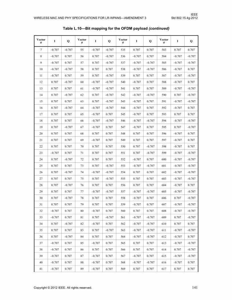
IEEEWIRELESS MAC AND PHY SPECIFICATIONS FOR LR-WPANS—AMENDMENT 3 Std 802.15.4g-2012
7 –0.707 –0.707 55 –0.707 –0.707 535 0.707 0.707 583 0.707 0.707
8 –0.707 0.707 56 0.707 –0.707 536 –0.707 0.707 584 –0.707 –0.707
9 –0.707 0.707 57 0.707 –0.707 537 –0.707 –0.707 585 –0.707 –0.707
10 –0.707 –0.707 58 0.707 0.707 538 –0.707 –0.707 586 –0.707 0.707
11 –0.707 0.707 59 0.707 –0.707 539 0.707 0.707 587 –0.707 –0.707
12 0.707 –0.707 60 –0.707 –0.707 540 –0.707 0.707 588 –0.707 0.707
13 0.707 0.707 61 –0.707 –0.707 541 0.707 0.707 589 –0.707 –0.707
14 0.707 –0.707 62 0.707 –0.707 542 –0.707 –0.707 590 0.707 –0.707
15 0.707 0.707 63 0.707 –0.707 543 –0.707 0.707 591 –0.707 –0.707
16 0.707 –0.707 64 –0.707 –0.707 544 –0.707 0.707 592 –0.707 0.707
17 0.707 0.707 65 –0.707 0.707 545 –0.707 0.707 593 0.707 0.707
18 0.707 0.707 66 –0.707 –0.707 546 –0.707 –0.707 594 –0.707 –0.707
19 0.707 –0.707 67 –0.707 0.707 547 –0.707 0.707 595 0.707 –0.707
20 0.707 0.707 68 0.707 0.707 548 0.707 0.707 596 –0.707 0.707
21 0.707 0.707 69 –0.707 0.707 549 0.707 0.707 597 –0.707 0.707
22 0.707 0.707 70 0.707 0.707 550 0.707 –0.707 598 –0.707 0.707
23 –0.707 0.707 71 0.707 0.707 551 0.707 –0.707 599 –0.707 –0.707
24 0.707 –0.707 72 0.707 0.707 552 –0.707 0.707 600 –0.707 –0.707
25 0.707 0.707 73 0.707 –0.707 553 –0.707 –0.707 601 –0.707 –0.707
26 0.707 –0.707 74 –0.707 –0.707 554 0.707 0.707 602 –0.707 –0.707
27 0.707 0.707 75 0.707 –0.707 555 0.707 0.707 603 –0.707 –0.707
28 0.707 –0.707 76 0.707 0.707 556 0.707 0.707 604 –0.707 0.707
29 0.707 0.707 77 –0.707 –0.707 557 –0.707 –0.707 605 –0.707 –0.707
30 0.707 –0.707 78 0.707 0.707 558 –0.707 0.707 606 0.707 –0.707
31 0.707 0.707 79 0.707 0.707 559 –0.707 0.707 607 –0.707 –0.707
32 –0.707 0.707 80 –0.707 0.707 560 0.707 0.707 608 –0.707 –0.707
33 –0.707 0.707 81 0.707 –0.707 561 –0.707 –0.707 609 0.707 –0.707
34 0.707 –0.707 82 –0.707 0.707 562 –0.707 –0.707 610 0.707 0.707
35 0.707 0.707 83 0.707 –0.707 563 –0.707 –0.707 611 –0.707 –0.707
36 0.707 –0.707 84 0.707 0.707 564 –0.707 –0.707 612 –0.707 0.707
37 –0.707 0.707 85 –0.707 0.707 565 0.707 0.707 613 –0.707 –0.707
38 –0.707 0.707 86 0.707 0.707 566 0.707 0.707 614 0.707 –0.707
39 –0.707 0.707 87 –0.707 0.707 567 –0.707 0.707 615 –0.707 –0.707
40 –0.707 0.707 88 –0.707 0.707 568 –0.707 –0.707 616 –0.707 0.707
41 –0.707 0.707 89 –0.707 0.707 569 0.707 0.707 617 0.707 0.707
Table L.10—Bit mapping for the OFDM payload (continued)
Vector# I Q Vector
# I Q Vector# I Q Vector
# I Q
Copyright © 2012 IEEE. All rights reserved. 141

IEEEStd 802.15.4g-2012 LOCAL AND METROPOLITAN AREA NETWORKS—PART 15.4:
L.4.5 Frequency spreading
In this example, no frequency spreading is applied to the OFDM payload. The vectors from Table L.10 are mapped directly into the frequency domain. The next paragraphs illustrate the mapping in the frequency domain, taking into account the pilot tones, the DC tone, and the guard tones.
L.5 Conversion from frequency domain to time domain
L.5.1 Pilot, DC, and guard tone insertion
The following steps are applied to both the OFDM header and the OFDM payload. Before going to the next steps, Table L.6 and Table L.10 should be appended, resulting in 19 symbols of 48 bins in the frequency domain. The 48 bins are mapped in the frequency domain by inserting pilot tones, guard tones, and a DC tone, as defined in 18.2.3.7, and the first and last three symbols of the complete packet in the frequency domain are given in Table L.11.
42 –0.707 0.707 90 0.707 0.707 570 –0.707 –0.707 618 0.707 0.707
43 0.707 –0.707 91 –0.707 –0.707 571 –0.707 –0.707 619 0.707 –0.707
44 0.707 0.707 92 –0.707 0.707 572 0.707 0.707 620 –0.707 –0.707
45 0.707 0.707 93 –0.707 0.707 573 0.707 –0.707 621 0.707 0.707
46 –0.707 0.707 94 0.707 0.707 574 0.707 –0.707 622 0.707 –0.707
47 0.707 –0.707 95 –0.707 0.707 575 0.707 0.707 623 –0.707 –0.707
48 0.707 –0.707 96 –0.707 –0.707 576 0.707 –0.707 624 –0.707 0.707
Table L.11—Complete packet in the frequency domain (first and last three symbols)
Subcarrier Symbol 1 Symbol 2 Symbol 3 Symbol 17 Symbol 18 Symbol 19
–32 0 + 0i 0 + 0i 0 + 0i 0 + 0i 0 + 0i 0 + 0i
–31 0 + 0i 0 + 0i 0 + 0i 0 + 0i 0 + 0i 0 + 0i
–30 0 + 0i 0 + 0i 0 + 0i 0 + 0i 0 + 0i 0 + 0i
–29 0 + 0i 0 + 0i 0 + 0i 0 + 0i 0 + 0i 0 + 0i
–28 0 + 0i 0 + 0i 0 + 0i 0 + 0i 0 + 0i 0 + 0i
–27 0 + 0i 0 + 0i 0 + 0i 0 + 0i 0 + 0i 0 + 0i
–26 0 – 1i 0 – 1i 0 + 1i –0.707 + 0.707i 1 + 0i –0.707 + 0.707i
–25 0 + 1i 0 –1i 0 + 1i –0.707 – 0.707i –0.707 – 0.707i –0.707 – 0.707i
–24 0 + 1i 0 – 1i 0 – 1i 0.707 + 0.707i –0.707 + 0.707i –0.707 + 0.707i
Table L.10—Bit mapping for the OFDM payload (continued)
Vector# I Q Vector
# I Q Vector# I Q Vector
# I Q
142 Copyright © 2012 IEEE. All rights reserved.

IEEEWIRELESS MAC AND PHY SPECIFICATIONS FOR LR-WPANS—AMENDMENT 3 Std 802.15.4g-2012
–23 0 + 1i 0 + 1i 0 – 1i 0.707 – 0.707i –0.707 + 0.707i –0.707 – 0.707i
–22 0 – 1i 1 + 0i 0 + 1i 0.707 – 0.707i –0.707 – 0.707i 1 + 0i
–21 0 + 1i 0 – 1i 0 – 1i 0.707 – 0.707i –0.707 + 0.707i 0.707 – 0.707i
–20 0 + 1i 0 – 1i 0 – 1i –0.707 – 0.707i –0.707 + 0.707i –0.707 + 0.707i
–19 0 – 1i 0 + 1i 0 – 1i –0.707 – 0.707i 0.707 + 0.707i 0.707 + 0.707i
–18 0 – 1i 0 + 1i –1 + 0i 1 + 0i –0.707 + 0.707i –0.707 – 0.707i
–17 0 + 1i 0 + 1i 0 – 1i 0.707 + 0.707i –0.707 – 0.707i –0.707 – 0.707i
–16 0 + 1i 0 + 1i 0 + 1i –0.707 – 0.707i –0.707 – 0.707i –0.707 + 0.707i
–15 0 + 1i 0 – 1i 0 + 1i 0.707 + 0.707i 0.707 + 0.707i –0.707 – 0.707i
–14 –1 + 0i 0 – 1i 0 – 1i 0.707 – 0.707i 1 + 0i –0.707 + 0.707i
–13 1 + 0i 1 + 0i –1 + 0i –0.707 – 0.707i –0.707 + 0.707i –0.707 – 0.707i
–12 0 – 1i 0 + 1i 0 – 1i –0.707 + 0.707i 0.707 + 0.707i 0.707 – 0.707i
–11 1 + 0i –1 + 0i –1 + 0i –0.707 – 0.707i –0.707 – 0.707i –0.707 – 0.707i
–10 0 + 1i 1 + 0i 0 – 1i 0.707 + 0.707i –0.707 + 0.707i –1 + 0i
–9 1 + 0i 0 + 1i –1 + 0i –0.707 – 0.707i –0.707 + 0.707i –0.707 + 0.707i
–8 0 – 1i 1 + 0i 0 + 1i 0.707 + 0.707i –0.707 + 0.707i 0.707 + 0.707i
–7 1 + 0i 0 + 1i –1 + 0i 0.707 + 0.707i –0.707 – 0.707i –0.707 – 0.707i
–6 0 – 1i 1 + 0i 1 + 0i –1 + 0i –0.707 + 0.707i 0.707 – 0.707i
–5 1 + 0i 0 + 1i 0 – 1i 0.707 + 0.707i 0.707 + 0.707i –0.707 + 0.707i
–4 0 – 1i –1 + 0i 1 + 0i –0.707 + 0.707i 0.707 + 0.707i –0.707 + 0.707i
–3 1 + 0i 0 – 1i 0 – 1i 0.707 – 0.707i 0.707 – 0.707i –0.707 + 0.707i
–2 –1 + 0i –1 + 0i 1 + 0i 0.707 – 0.707i –1 + 0i –0.707 – 0.707i
–1 0 + 1i 0 – 1i 0 – 1i 0.707 + 0.707i 0.707 – 0.707i –0.707 – 0.707i
0 0 + 0i 0 + 0i 0 + 0i 0 + 0i 0 + 0i 0 + 0i
1 –1 + 0i –1 + 0i 1 + 0i –0.707 + 0.707i –0.707 + 0.707i –0.707 – 0.707i
2 –1 + 0i 1 + 0i –1 + 0i 0.707 – 0.707i –0.707 – 0.707i –0.707 – 0.707i
3 1 + 0i 1 + 0i –1 + 0i 0.707 + 0.707i 0.707 + 0.707i –0.707 – 0.707i
4 –1 + 0i –1 + 0i 1 + 0i –0.707 + 0.707i 0.707 + 0.707i –0.707 + 0.707i
5 –1 + 0i –1 + 0i 1 + 0i –0.707 – 0.707i 0.707 + 0.707i –0.707 – 0.707i
6 –1 + 0i –1 + 0i 1 + 0i 1 + 0i –0.707 – 0.707i 0.707 – 0.707i
7 1 + 0i 1 + 0i 1 + 0i 0.707 + 0.707i –0.707 + 0.707i –0.707 – 0.707i
8 1 + 0i 1 + 0i –1 + 0i –0.707 – 0.707i –0.707 + 0.707i –0.707 – 0.707i
Table L.11—Complete packet in the frequency domain (first and last three symbols) (continued)
Subcarrier Symbol 1 Symbol 2 Symbol 3 Symbol 17 Symbol 18 Symbol 19
Copyright © 2012 IEEE. All rights reserved. 143
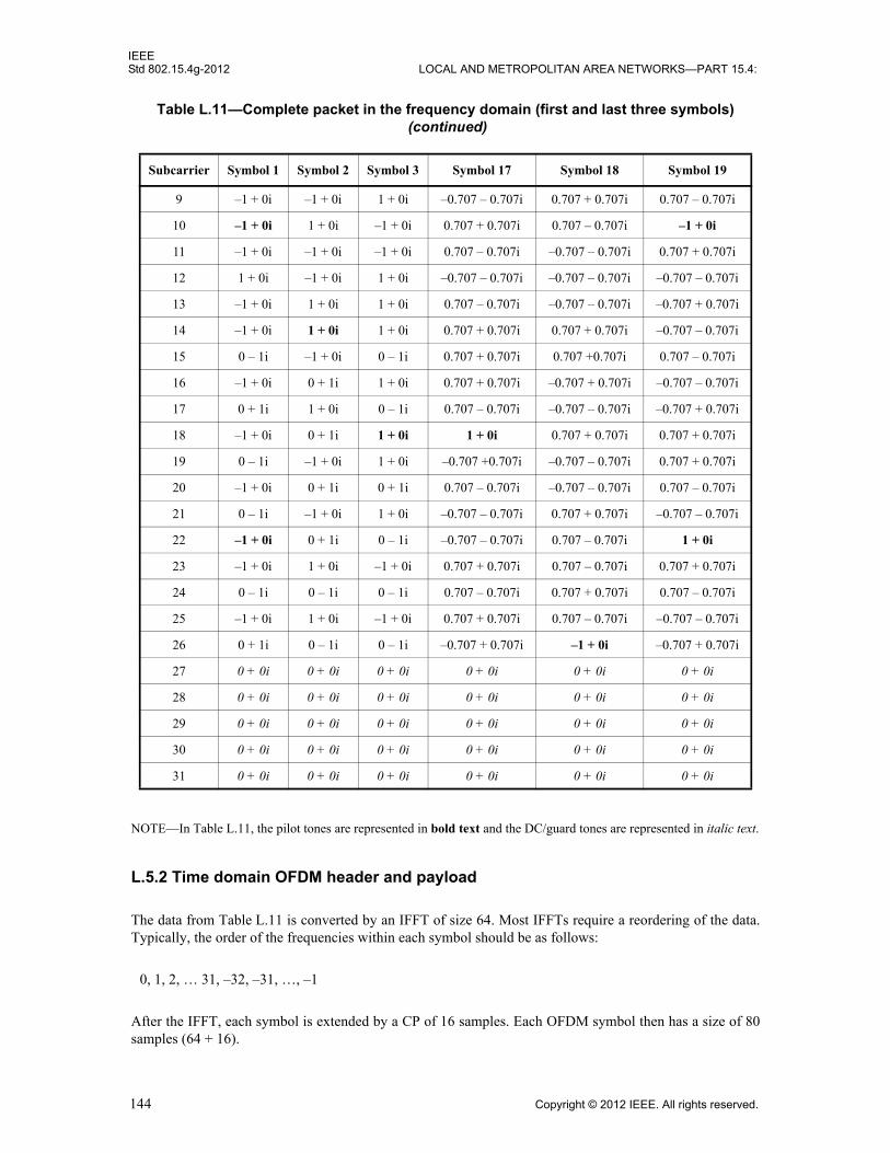
IEEEStd 802.15.4g-2012 LOCAL AND METROPOLITAN AREA NETWORKS—PART 15.4:
NOTE—In Table L.11, the pilot tones are represented in bold text and the DC/guard tones are represented in italic text.
L.5.2 Time domain OFDM header and payload
The data from Table L.11 is converted by an IFFT of size 64. Most IFFTs require a reordering of the data. Typically, the order of the frequencies within each symbol should be as follows:
0, 1, 2, … 31, –32, –31, …, –1
After the IFFT, each symbol is extended by a CP of 16 samples. Each OFDM symbol then has a size of 80 samples (64 + 16).
9 –1 + 0i –1 + 0i 1 + 0i –0.707 – 0.707i 0.707 + 0.707i 0.707 – 0.707i
10 –1 + 0i 1 + 0i –1 + 0i 0.707 + 0.707i 0.707 – 0.707i –1 + 0i
11 –1 + 0i –1 + 0i –1 + 0i 0.707 – 0.707i –0.707 – 0.707i 0.707 + 0.707i
12 1 + 0i –1 + 0i 1 + 0i –0.707 – 0.707i –0.707 – 0.707i –0.707 – 0.707i
13 –1 + 0i 1 + 0i 1 + 0i 0.707 – 0.707i –0.707 – 0.707i –0.707 + 0.707i
14 –1 + 0i 1 + 0i 1 + 0i 0.707 + 0.707i 0.707 + 0.707i –0.707 – 0.707i
15 0 – 1i –1 + 0i 0 – 1i 0.707 + 0.707i 0.707 +0.707i 0.707 – 0.707i
16 –1 + 0i 0 + 1i 1 + 0i 0.707 + 0.707i –0.707 + 0.707i –0.707 – 0.707i
17 0 + 1i 1 + 0i 0 – 1i 0.707 – 0.707i –0.707 – 0.707i –0.707 + 0.707i
18 –1 + 0i 0 + 1i 1 + 0i 1 + 0i 0.707 + 0.707i 0.707 + 0.707i
19 0 – 1i –1 + 0i 1 + 0i –0.707 +0.707i –0.707 – 0.707i 0.707 + 0.707i
20 –1 + 0i 0 + 1i 0 + 1i 0.707 – 0.707i –0.707 – 0.707i 0.707 – 0.707i
21 0 – 1i –1 + 0i 1 + 0i –0.707 – 0.707i 0.707 + 0.707i –0.707 – 0.707i
22 –1 + 0i 0 + 1i 0 – 1i –0.707 – 0.707i 0.707 – 0.707i 1 + 0i
23 –1 + 0i 1 + 0i –1 + 0i 0.707 + 0.707i 0.707 – 0.707i 0.707 + 0.707i
24 0 – 1i 0 – 1i 0 – 1i 0.707 – 0.707i 0.707 + 0.707i 0.707 – 0.707i
25 –1 + 0i 1 + 0i –1 + 0i 0.707 + 0.707i 0.707 – 0.707i –0.707 – 0.707i
26 0 + 1i 0 – 1i 0 – 1i –0.707 + 0.707i –1 + 0i –0.707 + 0.707i
27 0 + 0i 0 + 0i 0 + 0i 0 + 0i 0 + 0i 0 + 0i
28 0 + 0i 0 + 0i 0 + 0i 0 + 0i 0 + 0i 0 + 0i
29 0 + 0i 0 + 0i 0 + 0i 0 + 0i 0 + 0i 0 + 0i
30 0 + 0i 0 + 0i 0 + 0i 0 + 0i 0 + 0i 0 + 0i
31 0 + 0i 0 + 0i 0 + 0i 0 + 0i 0 + 0i 0 + 0i
Table L.11—Complete packet in the frequency domain (first and last three symbols) (continued)
Subcarrier Symbol 1 Symbol 2 Symbol 3 Symbol 17 Symbol 18 Symbol 19
144 Copyright © 2012 IEEE. All rights reserved.

IEEEWIRELESS MAC AND PHY SPECIFICATIONS FOR LR-WPANS—AMENDMENT 3 Std 802.15.4g-2012
The resulting data in the time domain has 1520 samples ( ) and is represented in L.7 (complete packet).
L.6 Generation of the preamble
L.6.1 Generation of the STF
As defined in 18.2.1.1, the STF consists of 4 symbols. The resulting STF is equivalent to 20 repetitions of the 16-sample time domain pattern given in Table L.12.
NOTE—The last 2 repetitions are negated.
L.6.2 Generation of the LTF
As defined in 18.2.1.2, the LTF consists of the time domain pattern given in Table L.13.
The samples 1 through 32 are part of the CP for the LTF. They are simply a copy of samples 65 through 96. The samples 97 through 160 are a repetition of samples 33 through 96.
Table L.12—STF time domain pattern
Sample # I Q
1 0.6505 0
2 1.0989 0.6505
3 0.46 –1.301
4 –0.9531 –0.6505
5 0 0
6 0.9531 0.6505
7 –0.46 1.301
8 –1.0989 –0.6505
9 –0.6505 0
10 –1.0989 0.6505
11 –0.46 –1.301
12 0.9531 –0.6505
13 0 0
14 –0.9531 0.6505
15 0.46 1.301
16 1.0989 –0.6505
19 80×
Copyright © 2012 IEEE. All rights reserved. 145

IEEEStd 802.15.4g-2012 LOCAL AND METROPOLITAN AREA NETWORKS—PART 15.4:
Table L.13—LTF in time domain
Sample # I Q Sample # I Q
33 –0.75 0 65 1.25 0
34 0.5069 –0.5395 66 –0.3216 –0.5171
35 0.147 0.178 67 –0.564 –0.4328
36 –0.5541 0.4205 68 0.8594 0.5478
37 0.2817 –0.9077 69 0.0111 –0.4458
38 –0.5326 0.3518 70 –0.9756 –0.4563
39 –0.3165 1.0258 71 –1.1903 0.3727
40 –0.5391 0.207 72 –0.7761 –0.0741
41 –0.6036 1.1339 73 0.1036 –0.6339
42 0.8113 0.6423 74 0.2871 –1.2165
43 –0.6222 –0.3373 75 0.4219 –0.6784
44 –0.4653 –0.3832 76 0.8836 –0.4284
45 1.1802 0.4189 77 0.5269 0.2276
46 0.0015 1.1597 78 –0.6312 0.5158
47 0.4623 0.2948 79 –0.3382 –0.9638
48 1.0998 –0.4827 80 0.3459 0.1333
49 0.25 –1.25 81 0.25 1.25
50 0.3459 –0.1333 82 1.0998 0.4827
51 –0.3382 0.9638 83 0.4623 –0.2948
52 –0.6312 –0.5158 84 0.0015 –1.1597
53 0.5269 –0.2276 85 1.1802 –0.4189
54 0.8836 0.4284 86 –0.4653 0.3832
55 0.4219 0.6784 87 –0.6222 0.3373
56 0.2871 1.2165 88 0.8113 –0.6423
57 0.1036 0.6339 89 –0.6036 –1.1339
58 –0.7761 0.0741 90 –0.5391 –0.207
59 –1.1903 –0.3727 91 –0.3165 –1.0258
60 –0.9756 0.4563 92 –0.5326 –0.3518
61 0.0111 0.4458 93 0.2817 0.9077
62 0.8594 –0.5478 94 –0.5541 –0.4205
63 –0.564 0.4328 95 0.147 –0.178
64 –0.3216 0.5171 96 0.5069 0.5395
146 Copyright © 2012 IEEE. All rights reserved.
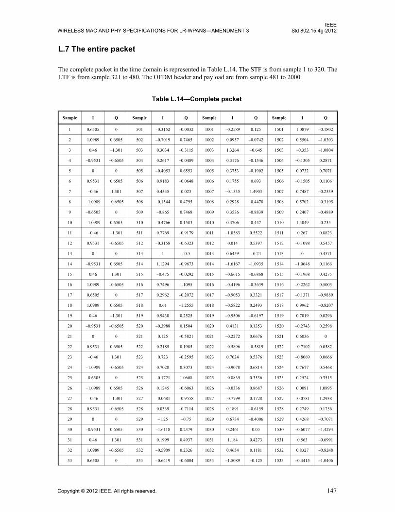
IEEEWIRELESS MAC AND PHY SPECIFICATIONS FOR LR-WPANS—AMENDMENT 3 Std 802.15.4g-2012
L.7 The entire packet
The complete packet in the time domain is represented in Table L.14. The STF is from sample 1 to 320. The LTF is from sample 321 to 480. The OFDM header and payload are from sample 481 to 2000.
Table L.14—Complete packet
Sample I Q Sample I Q Sample I Q Sample I Q
1 0.6505 0 501 –0.3152 –0.0032 1001 –0.2589 0.125 1501 1.0879 –0.1802
2 1.0989 0.6505 502 –0.7019 0.7465 1002 0.0957 –0.0742 1502 0.5504 –1.0303
3 0.46 –1.301 503 0.3034 –0.3115 1003 1.3264 –0.645 1503 –0.353 –1.0804
4 –0.9531 –0.6505 504 0.2617 –0.0489 1004 0.3176 –0.1546 1504 –0.1305 0.2871
5 0 0 505 –0.4053 0.6553 1005 0.3753 –0.1902 1505 0.0732 0.7071
6 0.9531 0.6505 506 0.9183 –0.0648 1006 0.1755 0.693 1506 –0.1505 0.1106
7 –0.46 1.301 507 0.4545 0.023 1007 –0.1535 1.4903 1507 0.7487 –0.2539
8 –1.0989 –0.6505 508 –0.1544 0.4795 1008 0.2928 –0.4478 1508 0.5702 –0.3195
9 –0.6505 0 509 –0.865 0.7468 1009 0.3536 –0.8839 1509 0.2407 –0.4889
10 –1.0989 0.6505 510 –0.4766 0.1583 1010 0.3706 0.447 1510 1.4049 0.235
11 –0.46 –1.301 511 0.7769 –0.9179 1011 –1.0583 0.5522 1511 0.267 0.8823
12 0.9531 –0.6505 512 –0.3158 –0.6323 1012 0.014 0.5397 1512 –0.1098 0.5457
13 0 0 513 1 –0.5 1013 0.6459 –0.24 1513 0 0.4571
14 –0.9531 0.6505 514 1.1294 –0.9673 1014 –1.6167 –1.0935 1514 –1.0648 0.1166
15 0.46 1.301 515 –0.475 –0.0292 1015 –0.6615 –0.6868 1515 –0.1968 0.4275
16 1.0989 –0.6505 516 0.7496 1.1095 1016 –0.4196 –0.3639 1516 –0.2262 0.5005
17 0.6505 0 517 0.2962 –0.2072 1017 –0.9053 0.3321 1517 –0.1371 –0.9889
18 1.0989 0.6505 518 0.61 –1.2555 1018 –0.5822 0.2493 1518 0.9962 –0.8207
19 0.46 –1.301 519 0.9438 0.2525 1019 –0.9506 –0.6197 1519 0.7019 0.0296
20 –0.9531 –0.6505 520 –0.3988 0.1504 1020 0.4131 0.1353 1520 –0.2743 0.2598
21 0 0 521 0.125 –0.5821 1021 –0.2272 0.0676 1521 0.6036 0
22 0.9531 0.6505 522 0.2185 0.1985 1022 –0.5896 –0.5819 1522 –0.7102 0.0582
23 –0.46 1.301 523 0.723 –0.2595 1023 0.7024 0.5376 1523 –0.8069 0.0666
24 –1.0989 –0.6505 524 0.7028 0.3073 1024 –0.9078 0.6814 1524 0.7677 0.5468
25 –0.6505 0 525 –0.1721 1.0608 1025 –0.8839 0.3536 1525 0.2524 0.3515
26 –1.0989 0.6505 526 0.1245 –0.6063 1026 –0.0336 0.8687 1526 0.0091 1.0895
27 –0.46 –1.301 527 –0.0681 –0.9558 1027 –0.7799 0.1728 1527 –0.0781 1.2938
28 0.9531 –0.6505 528 0.0339 –0.7114 1028 0.1891 –0.6159 1528 0.2749 0.1756
29 0 0 529 –1.25 –0.75 1029 0.6734 –0.4006 1529 0.4268 –0.7071
30 –0.9531 0.6505 530 –1.6118 0.2379 1030 0.2461 0.05 1530 –0.6077 –1.4293
31 0.46 1.301 531 0.1999 0.4937 1031 1.184 0.4273 1531 0.563 –0.6991
32 1.0989 –0.6505 532 –0.5909 0.2326 1032 0.4654 0.1181 1532 0.8327 –0.8248
33 0.6505 0 533 –0.6419 –0.6004 1033 –1.5089 –0.125 1533 –0.4415 –1.0406
Copyright © 2012 IEEE. All rights reserved. 147
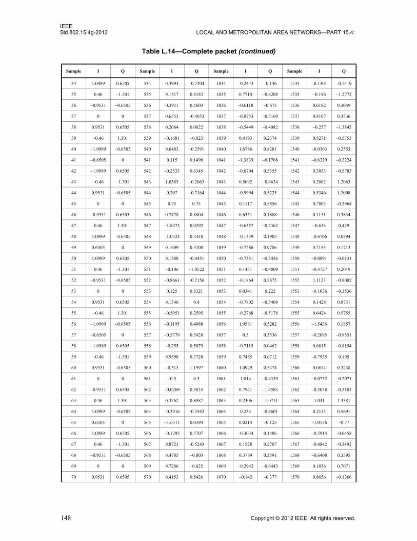
IEEEStd 802.15.4g-2012 LOCAL AND METROPOLITAN AREA NETWORKS—PART 15.4:
34 1.0989 0.6505 534 0.3993 –0.7404 1034 –0.2443 –0.146 1534 –0.1301 –0.7419
35 0.46 –1.301 535 0.1517 0.8183 1035 0.7714 –0.6208 1535 –0.196 –1.2772
36 –0.9531 –0.6505 536 0.3911 0.5603 1036 –0.6118 –0.675 1536 0.6182 0.3049
37 0 0 537 0.6553 –0.4053 1037 –0.8753 –0.5169 1537 0.8107 0.3536
38 0.9531 0.6505 538 0.2064 0.0022 1038 –0.5449 –0.4082 1538 –0.257 –1.3845
39 –0.46 1.301 539 –0.1681 –0.023 1039 0.4193 0.2374 1539 0.5271 –0.5753
40 –1.0989 –0.6505 540 0.6483 –0.2591 1040 1.6786 0.8281 1540 –0.0303 0.2553
41 –0.6505 0 541 0.115 0.1496 1041 –1.3839 –0.1768 1541 –0.6329 –0.3224
42 –1.0989 0.6505 542 –0.2533 0.6345 1042 –0.6704 0.5355 1542 0.3853 –0.5783
43 –0.46 –1.301 543 1.0385 –0.2063 1043 0.5092 –0.4634 1543 0.2062 1.2063
44 0.9531 –0.6505 544 0.207 –0.7164 1044 –0.9994 0.5225 1544 0.5346 1.3008
45 0 0 545 0.75 0.75 1045 0.1117 0.5856 1545 0.7803 –0.3964
46 –0.9531 0.6505 546 0.7478 0.8804 1046 0.6351 0.1888 1546 0.1151 0.3834
47 0.46 1.301 547 –1.8473 0.0292 1047 –0.6357 –0.2362 1547 –0.634 0.429
48 1.0989 –0.6505 548 –1.0324 0.3448 1048 –0.1339 0.1905 1548 –0.6766 0.0394
49 0.6505 0 549 0.1609 0.3108 1049 –0.7286 0.9786 1549 0.7144 0.1713
50 1.0989 0.6505 550 0.1388 –0.4451 1050 –0.7351 –0.3456 1550 –0.0891 –0.0131
51 0.46 –1.301 551 –0.106 –1.0522 1051 0.1451 –0.4809 1551 –0.4727 0.2019
52 –0.9531 –0.6505 552 –0.8661 –0.2156 1052 –0.1864 0.2875 1552 1.1123 –0.8002
53 0 0 553 0.125 0.8321 1053 0.0341 0.222 1553 –0.1036 –0.3536
54 0.9531 0.6505 554 0.1346 0.4 1054 –0.7802 –0.3408 1554 0.1428 0.8731
55 –0.46 1.301 555 –0.5951 0.2595 1055 –0.2768 –0.5178 1555 0.6424 0.5755
56 –1.0989 –0.6505 556 –0.1195 0.4088 1056 1.9581 0.5282 1556 –1.5436 0.1857
57 –0.6505 0 557 –0.5779 0.5428 1057 0.5 0.3536 1557 –0.2095 –0.9551
58 –1.0989 0.6505 558 –0.255 0.5079 1058 –0.7115 0.0462 1558 0.6815 –0.8154
59 –0.46 –1.301 559 0.9598 0.3728 1059 0.7485 0.6712 1559 –0.7935 0.195
60 0.9531 –0.6505 560 –0.313 1.1997 1060 1.0929 0.5474 1560 0.0674 0.3238
61 0 0 561 –0.5 0.5 1061 1.014 –0.4339 1561 –0.0732 –0.2071
62 –0.9531 0.6505 562 –0.0269 0.5835 1062 0.7941 –1.4585 1562 –0.3058 –0.3181
63 0.46 1.301 563 0.3762 0.8987 1063 0.2306 –1.0711 1563 1.041 1.3381
64 1.0989 –0.6505 564 –0.3916 –0.3543 1064 0.234 –0.4601 1564 0.2113 0.5691
65 0.6505 0 565 –1.6311 0.0394 1065 0.0214 –0.125 1565 –1.0156 –0.77
66 1.0989 0.6505 566 –0.1295 0.5707 1066 –0.3034 0.1486 1566 –0.5914 –0.0458
67 0.46 –1.301 567 0.8723 –0.5243 1067 0.1528 0.2707 1567 –0.4842 –0.3492
68 –0.9531 –0.6505 568 0.4785 –0.803 1068 0.3789 0.3591 1568 –0.6408 0.3395
69 0 0 569 0.7286 –0.625 1069 –0.2942 –0.6443 1569 0.1036 0.7071
70 0.9531 0.6505 570 0.4153 0.5426 1070 –0.142 –0.377 1570 0.8656 –0.1366
Table L.14—Complete packet (continued)
Sample I Q Sample I Q Sample I Q Sample I Q
148 Copyright © 2012 IEEE. All rights reserved.
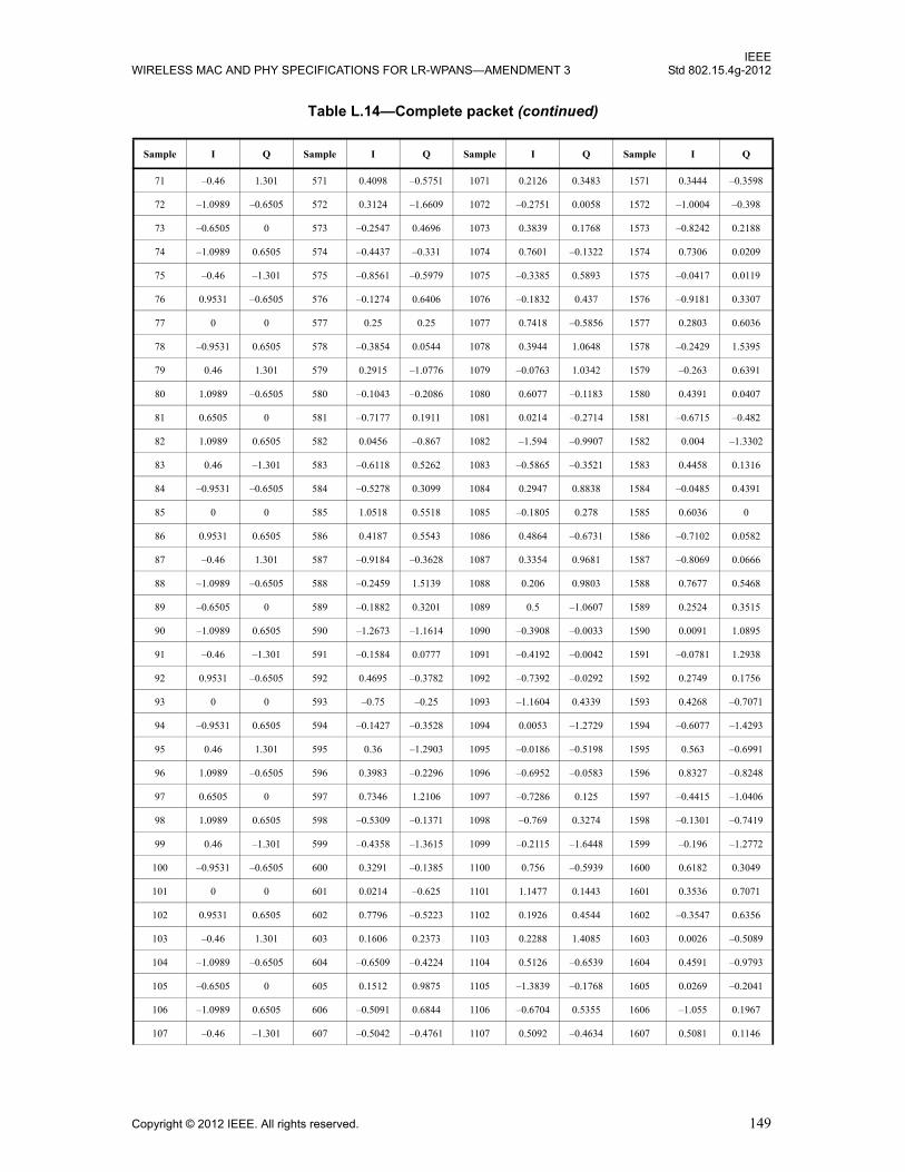
IEEEWIRELESS MAC AND PHY SPECIFICATIONS FOR LR-WPANS—AMENDMENT 3 Std 802.15.4g-2012
71 –0.46 1.301 571 0.4098 –0.5751 1071 0.2126 0.3483 1571 0.3444 –0.3598
72 –1.0989 –0.6505 572 0.3124 –1.6609 1072 –0.2751 0.0058 1572 –1.0004 –0.398
73 –0.6505 0 573 –0.2547 0.4696 1073 0.3839 0.1768 1573 –0.8242 0.2188
74 –1.0989 0.6505 574 –0.4437 –0.331 1074 0.7601 –0.1322 1574 0.7306 0.0209
75 –0.46 –1.301 575 –0.8561 –0.5979 1075 –0.3385 0.5893 1575 –0.0417 0.0119
76 0.9531 –0.6505 576 –0.1274 0.6406 1076 –0.1832 0.437 1576 –0.9181 0.3307
77 0 0 577 0.25 0.25 1077 0.7418 –0.5856 1577 0.2803 0.6036
78 –0.9531 0.6505 578 –0.3854 0.0544 1078 0.3944 1.0648 1578 –0.2429 1.5395
79 0.46 1.301 579 0.2915 –1.0776 1079 –0.0763 1.0342 1579 –0.263 0.6391
80 1.0989 –0.6505 580 –0.1043 –0.2086 1080 0.6077 –0.1183 1580 0.4391 0.0407
81 0.6505 0 581 –0.7177 0.1911 1081 0.0214 –0.2714 1581 –0.6715 –0.482
82 1.0989 0.6505 582 0.0456 –0.867 1082 –1.594 –0.9907 1582 0.004 –1.3302
83 0.46 –1.301 583 –0.6118 0.5262 1083 –0.5865 –0.3521 1583 0.4458 0.1316
84 –0.9531 –0.6505 584 –0.5278 0.3099 1084 0.2947 0.8838 1584 –0.0485 0.4391
85 0 0 585 1.0518 0.5518 1085 –0.1805 0.278 1585 0.6036 0
86 0.9531 0.6505 586 0.4187 0.5543 1086 0.4864 –0.6731 1586 –0.7102 0.0582
87 –0.46 1.301 587 –0.9184 –0.3628 1087 0.3354 0.9681 1587 –0.8069 0.0666
88 –1.0989 –0.6505 588 –0.2459 1.5139 1088 0.206 0.9803 1588 0.7677 0.5468
89 –0.6505 0 589 –0.1882 0.3201 1089 0.5 –1.0607 1589 0.2524 0.3515
90 –1.0989 0.6505 590 –1.2673 –1.1614 1090 –0.3908 –0.0033 1590 0.0091 1.0895
91 –0.46 –1.301 591 –0.1584 0.0777 1091 –0.4192 –0.0042 1591 –0.0781 1.2938
92 0.9531 –0.6505 592 0.4695 –0.3782 1092 –0.7392 –0.0292 1592 0.2749 0.1756
93 0 0 593 –0.75 –0.25 1093 –1.1604 0.4339 1593 0.4268 –0.7071
94 –0.9531 0.6505 594 –0.1427 –0.3528 1094 0.0053 –1.2729 1594 –0.6077 –1.4293
95 0.46 1.301 595 0.36 –1.2903 1095 –0.0186 –0.5198 1595 0.563 –0.6991
96 1.0989 –0.6505 596 0.3983 –0.2296 1096 –0.6952 –0.0583 1596 0.8327 –0.8248
97 0.6505 0 597 0.7346 1.2106 1097 –0.7286 0.125 1597 –0.4415 –1.0406
98 1.0989 0.6505 598 –0.5309 –0.1371 1098 –0.769 0.3274 1598 –0.1301 –0.7419
99 0.46 –1.301 599 –0.4358 –1.3615 1099 –0.2115 –1.6448 1599 –0.196 –1.2772
100 –0.9531 –0.6505 600 0.3291 –0.1385 1100 0.756 –0.5939 1600 0.6182 0.3049
101 0 0 601 0.0214 –0.625 1101 1.1477 0.1443 1601 0.3536 0.7071
102 0.9531 0.6505 602 0.7796 –0.5223 1102 0.1926 0.4544 1602 –0.3547 0.6356
103 –0.46 1.301 603 0.1606 0.2373 1103 0.2288 1.4085 1603 0.0026 –0.5089
104 –1.0989 –0.6505 604 –0.6509 –0.4224 1104 0.5126 –0.6539 1604 0.4591 –0.9793
105 –0.6505 0 605 0.1512 0.9875 1105 –1.3839 –0.1768 1605 0.0269 –0.2041
106 –1.0989 0.6505 606 –0.5091 0.6844 1106 –0.6704 0.5355 1606 –1.055 0.1967
107 –0.46 –1.301 607 –0.5042 –0.4761 1107 0.5092 –0.4634 1607 0.5081 0.1146
Table L.14—Complete packet (continued)
Sample I Q Sample I Q Sample I Q Sample I Q
Copyright © 2012 IEEE. All rights reserved. 149
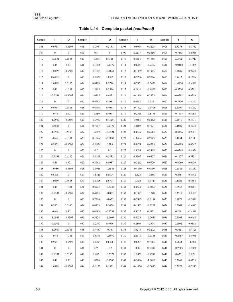
IEEEStd 802.15.4g-2012 LOCAL AND METROPOLITAN AREA NETWORKS—PART 15.4:
108 0.9531 –0.6505 608 0.795 0.3131 1108 –0.9994 0.5225 1608 1.3278 –0.1783
109 0 0 609 0.5 0 1109 0.1117 0.5856 1609 –0.7803 –0.6036
110 –0.9531 0.6505 610 –0.315 0.1515 1110 0.6351 0.1888 1610 0.0162 –0.7913
111 0.46 1.301 611 –0.3206 –0.2379 1111 –0.6357 –0.2362 1611 –0.0462 –0.069
112 1.0989 –0.6505 612 –0.3389 –0.1851 1112 –0.1339 0.1905 1612 0.1889 0.9928
113 0.6505 0 613 –0.8858 1.0589 1113 –0.7286 0.9786 1613 0.9413 0.1226
114 1.0989 0.6505 614 0.0198 0.3796 1114 –0.7351 –0.3456 1614 –1.4154 –0.4991
115 0.46 –1.301 615 1.5895 0.3596 1115 0.1451 –0.4809 1615 –0.5254 0.8781
116 –0.9531 –0.6505 616 1.0805 0.6855 1116 –0.1864 0.2875 1616 –0.0592 0.0519
117 0 0 617 0.6982 0.1982 1117 0.0341 0.222 1617 –0.3536 –1.4142
118 0.9531 0.6505 618 0.6706 0.4031 1118 –0.7802 –0.3408 1618 1.2199 –0.1272
119 –0.46 1.301 619 –0.359 0.4077 1119 –0.2768 –0.5178 1619 –0.1617 0.5988
120 –1.0989 –0.6505 620 –0.3933 0.1329 1120 1.9581 0.5282 1620 0.1019 0.3871
121 –0.6505 0 621 0.7917 –0.2772 1121 1.3107 0.7071 1621 0.4889 0.3932
122 –1.0989 0.6505 622 1.4009 –0.5524 1122 0.4326 0.6513 1622 –0.3196 0.2501
123 –0.46 –1.301 623 0.1046 –0.0037 1123 –1.0584 0.2543 1623 0.4854 0.711
124 0.9531 –0.6505 624 –1.0834 0.785 1124 0.0874 0.4525 1624 –0.6103 0.0647
125 0 0 625 –0.5 0.5 1125 1.3684 0.2468 1625 –0.6768 –0.6036
126 –0.9531 0.6505 626 –0.0269 0.5835 1126 0.3107 0.0857 1626 –0.1627 0.5331
127 0.46 1.301 627 0.3762 0.8987 1127 –0.3262 0.6729 1627 –0.4069 0.0439
128 1.0989 –0.6505 628 –0.3916 –0.3543 1128 –0.4839 0.6139 1628 0.1342 –0.7233
129 0.6505 0 629 –1.6311 0.0394 1129 –1.125 1.2286 1629 –0.2881 0.4492
130 1.0989 0.6505 630 –0.1295 0.5707 1130 –0.324 –0.0743 1630 0.4181 0.5584
131 0.46 –1.301 631 0.8723 –0.5243 1131 0.4623 –0.8069 1631 0.8552 0.0761
132 –0.9531 –0.6505 632 0.4785 –0.803 1132 –0.1397 1.1748 1632 0.3919 –0.0307
133 0 0 633 0.7286 –0.625 1133 –0.7499 –0.6194 1633 0.7071 –0.7071
134 0.9531 0.6505 634 0.4153 0.5426 1134 –0.1972 –0.7251 1634 0.2109 –1.4097
135 –0.46 1.301 635 0.4098 –0.5751 1135 0.9637 0.5971 1635 0.268 –1.4598
136 –1.0989 –0.6505 636 0.3124 –1.6609 1136 0.4623 –0.5046 1636 0.9103 0.0464
137 –0.6505 0 637 –0.2547 0.4696 1137 0.2803 1.2374 1637 0.6802 0.9112
138 –1.0989 0.6505 638 –0.4437 –0.331 1138 1.0275 0.5272 1638 –0.5451 –0.4129
139 –0.46 –1.301 639 –0.8561 –0.5979 1139 0.0113 –0.9355 1639 –0.2787 –0.9936
140 0.9531 –0.6505 640 –0.1274 0.6406 1140 –0.6204 0.7613 1640 1.0654 –1.368
141 0 0 641 0.25 –0.5 1141 –0.89 0.3108 1641 –0.2803 –1.1036
142 –0.9531 0.6505 642 0.403 –0.2371 1142 –1.2452 –0.4992 1642 –0.6351 1.079
143 0.46 1.301 643 1.0226 –0.1746 1143 –0.3086 –1.0016 1643 0.3168 0.6773
144 1.0989 –0.6505 644 –0.1153 0.1551 1144 –0.1656 –0.5035 1644 0.2175 –0.7115
Table L.14—Complete packet (continued)
Sample I Q Sample I Q Sample I Q Sample I Q
150 Copyright © 2012 IEEE. All rights reserved.

IEEEWIRELESS MAC AND PHY SPECIFICATIONS FOR LR-WPANS—AMENDMENT 3 Std 802.15.4g-2012
145 0.6505 0 645 0.4778 –0.134 1145 0.2714 0.625 1645 0.5587 0.5845
146 1.0989 0.6505 646 0.4828 –0.8943 1146 0.4795 0.083 1646 –0.004 0.698
147 0.46 –1.301 647 0.2801 0.123 1147 –0.6645 –0.1462 1647 –0.2452 –0.1038
148 –0.9531 –0.6505 648 –0.0148 1.1609 1148 –0.0025 –0.0595 1648 –0.2382 0.1114
149 0 0 649 –0.375 0.7286 1149 –0.1067 0.7151 1649 –0.7071 0
150 0.9531 0.6505 650 0.7524 0.5096 1150 –0.852 0.3955 1650 0.0234 0.1846
151 –0.46 1.301 651 –0.8567 0.3234 1151 0.5795 –0.6363 1651 –0.1089 –0.3372
152 –1.0989 –0.6505 652 –0.7367 –0.2166 1152 0.8012 0.0835 1652 –0.4989 –1.0441
153 –0.6505 0 653 1.2458 –0.0193 1153 0.25 0.3536 1653 0.2183 0.3139
154 –1.0989 0.6505 654 0.2994 0.2395 1154 0.3127 0.5918 1654 0.1714 0.7904
155 –0.46 –1.301 655 0.4325 –0.1663 1155 0.4818 –0.2727 1655 0.2852 –0.1249
156 0.9531 –0.6505 656 0.5498 –1.1755 1156 0.6819 –0.8599 1656 1.272 0.3506
157 0 0 657 0.5 –1.25 1157 –0.2648 –0.3504 1657 0.3232 0.8964
158 –0.9531 0.6505 658 0.3124 0.9187 1158 –0.2811 –1.3707 1658 –0.7321 0.3101
159 0.46 1.301 659 –0.3425 0.7625 1159 0.148 –0.1343 1659 0.1363 –0.3594
160 1.0989 –0.6505 660 0.5529 –1.2669 1160 0.0583 0.9129 1660 –1.0988 –0.3824
161 0.6505 0 661 –0.0529 –0.1736 1161 1.125 –0.0214 1661 –1.2119 0.2579
162 1.0989 0.6505 662 –0.4119 –0.0433 1162 0.6191 –0.3148 1662 0.3354 0.8325
163 0.46 –1.301 663 –0.5436 –0.9554 1163 –0.077 –1.3215 1663 –1.0846 0.8567
164 –0.9531 –0.6505 664 –1.8697 0.0768 1164 0.1305 –0.7331 1664 –0.7351 0.5842
165 0 0 665 –0.5518 –0.3018 1165 –1.2679 –0.4841 1665 0.3536 0.7071
166 0.9531 0.6505 666 1.1419 –0.446 1166 –0.4491 –0.5243 1666 –0.3547 0.6356
167 –0.46 1.301 667 0.8086 0.1402 1167 0.8201 0.9034 1667 0.0026 –0.5089
168 –1.0989 –0.6505 668 –0.1808 –0.1731 1168 –0.92 –0.1987 1668 0.4591 –0.9793
169 –0.6505 0 669 0.3092 0.347 1169 –1.1339 –0.1768 1669 0.0269 –0.2041
170 –1.0989 0.6505 670 0.7407 –0.2839 1170 –0.1195 1.1895 1670 –1.055 0.1967
171 –0.46 –1.301 671 –0.4095 –0.6668 1171 0.0654 0.0396 1671 0.5081 0.1146
172 0.9531 –0.6505 672 0.324 0.6626 1172 0.1217 –0.6245 1672 1.3278 –0.1783
173 0 0 673 0 0.75 1173 –0.2135 –0.2072 1673 –0.7803 –0.6036
174 –0.9531 0.6505 674 –0.8544 0.7334 1174 –0.0551 –0.0275 1674 0.0162 –0.7913
175 0.46 1.301 675 0.5255 0.2195 1175 0.4011 –0.037 1675 –0.0462 –0.069
176 1.0989 –0.6505 676 –0.2896 –0.4108 1176 –0.0622 –0.37 1676 0.1889 0.9928
177 0.6505 0 677 –0.5814 0.384 1177 –0.9786 –1.125 1677 0.9413 0.1226
178 1.0989 0.6505 678 0.7117 0.4746 1178 –0.4279 –0.6538 1678 –1.4154 –0.4991
179 0.46 –1.301 679 –0.2389 0.6096 1179 0.7792 0.3604 1679 –0.5254 0.8781
180 –0.9531 –0.6505 680 –0.8804 0.3611 1180 –0.259 –0.1115 1680 –0.0592 0.0519
181 0 0 681 –0.375 0.0214 1181 –0.7039 0.3885 1681 –0.6036 –1.0607
Table L.14—Complete packet (continued)
Sample I Q Sample I Q Sample I Q Sample I Q
Copyright © 2012 IEEE. All rights reserved. 151
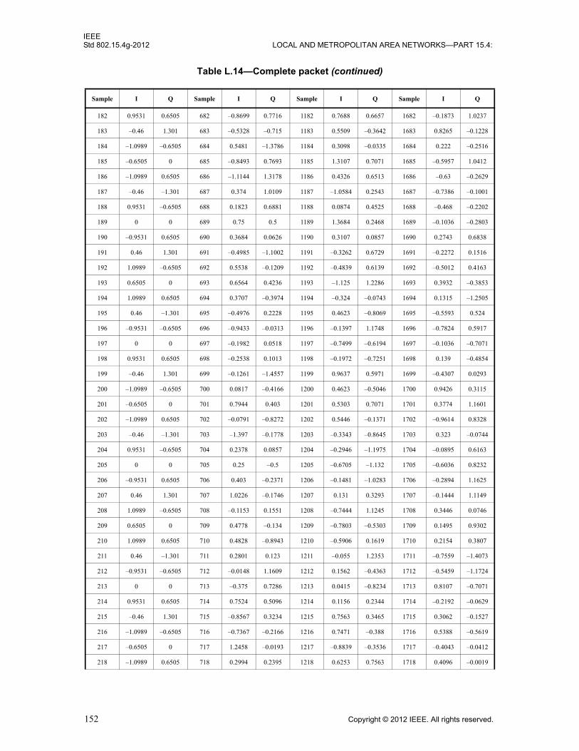
IEEEStd 802.15.4g-2012 LOCAL AND METROPOLITAN AREA NETWORKS—PART 15.4:
182 0.9531 0.6505 682 –0.8699 0.7716 1182 0.7688 0.6657 1682 –0.1873 1.0237
183 –0.46 1.301 683 –0.5328 –0.715 1183 0.5509 –0.3642 1683 0.8265 –0.1228
184 –1.0989 –0.6505 684 0.5481 –1.3786 1184 0.3098 –0.0335 1684 0.222 –0.2516
185 –0.6505 0 685 –0.8493 0.7693 1185 1.3107 0.7071 1685 –0.5957 1.0412
186 –1.0989 0.6505 686 –1.1144 1.3178 1186 0.4326 0.6513 1686 –0.63 –0.2629
187 –0.46 –1.301 687 0.374 1.0109 1187 –1.0584 0.2543 1687 –0.7386 –0.1001
188 0.9531 –0.6505 688 0.1823 0.6881 1188 0.0874 0.4525 1688 –0.468 –0.2202
189 0 0 689 0.75 0.5 1189 1.3684 0.2468 1689 –0.1036 –0.2803
190 –0.9531 0.6505 690 0.3684 0.0626 1190 0.3107 0.0857 1690 0.2743 0.6838
191 0.46 1.301 691 –0.4985 –1.1002 1191 –0.3262 0.6729 1691 –0.2272 0.1516
192 1.0989 –0.6505 692 0.5538 –0.1209 1192 –0.4839 0.6139 1692 –0.5012 0.4163
193 0.6505 0 693 0.6564 0.4236 1193 –1.125 1.2286 1693 0.3932 –0.3853
194 1.0989 0.6505 694 0.3707 –0.3974 1194 –0.324 –0.0743 1694 0.1315 –1.2505
195 0.46 –1.301 695 –0.4976 0.2228 1195 0.4623 –0.8069 1695 –0.5593 0.524
196 –0.9531 –0.6505 696 –0.9433 –0.0313 1196 –0.1397 1.1748 1696 –0.7824 0.5917
197 0 0 697 –0.1982 0.0518 1197 –0.7499 –0.6194 1697 –0.1036 –0.7071
198 0.9531 0.6505 698 –0.2538 0.1013 1198 –0.1972 –0.7251 1698 0.139 –0.4854
199 –0.46 1.301 699 –0.1261 –1.4557 1199 0.9637 0.5971 1699 –0.4307 0.0293
200 –1.0989 –0.6505 700 0.0817 –0.4166 1200 0.4623 –0.5046 1700 0.9426 0.3115
201 –0.6505 0 701 0.7944 0.403 1201 0.5303 0.7071 1701 0.3774 1.1601
202 –1.0989 0.6505 702 –0.0791 –0.8272 1202 0.5446 –0.1371 1702 –0.9614 0.8328
203 –0.46 –1.301 703 –1.397 –0.1778 1203 –0.3343 –0.8645 1703 0.323 –0.0744
204 0.9531 –0.6505 704 0.2378 0.0857 1204 –0.2946 –1.1975 1704 –0.0895 0.6163
205 0 0 705 0.25 –0.5 1205 –0.6705 –1.132 1705 –0.6036 0.8232
206 –0.9531 0.6505 706 0.403 –0.2371 1206 –0.1481 –1.0283 1706 –0.2894 1.1625
207 0.46 1.301 707 1.0226 –0.1746 1207 0.131 0.3293 1707 –0.1444 1.1149
208 1.0989 –0.6505 708 –0.1153 0.1551 1208 –0.7444 1.1245 1708 0.3446 0.0746
209 0.6505 0 709 0.4778 –0.134 1209 –0.7803 –0.5303 1709 0.1495 0.9302
210 1.0989 0.6505 710 0.4828 –0.8943 1210 –0.5906 0.1619 1710 0.2154 0.3807
211 0.46 –1.301 711 0.2801 0.123 1211 –0.055 1.2353 1711 –0.7559 –1.4073
212 –0.9531 –0.6505 712 –0.0148 1.1609 1212 0.1562 –0.4363 1712 –0.5459 –1.1724
213 0 0 713 –0.375 0.7286 1213 0.0415 –0.8234 1713 0.8107 –0.7071
214 0.9531 0.6505 714 0.7524 0.5096 1214 0.1156 0.2344 1714 –0.2192 –0.0629
215 –0.46 1.301 715 –0.8567 0.3234 1215 0.7563 0.3465 1715 0.3062 –0.1527
216 –1.0989 –0.6505 716 –0.7367 –0.2166 1216 0.7471 –0.388 1716 0.5388 –0.5619
217 –0.6505 0 717 1.2458 –0.0193 1217 –0.8839 –0.3536 1717 –0.4043 –0.0412
218 –1.0989 0.6505 718 0.2994 0.2395 1218 0.6253 0.7563 1718 0.4096 –0.0019
Table L.14—Complete packet (continued)
Sample I Q Sample I Q Sample I Q Sample I Q
152 Copyright © 2012 IEEE. All rights reserved.
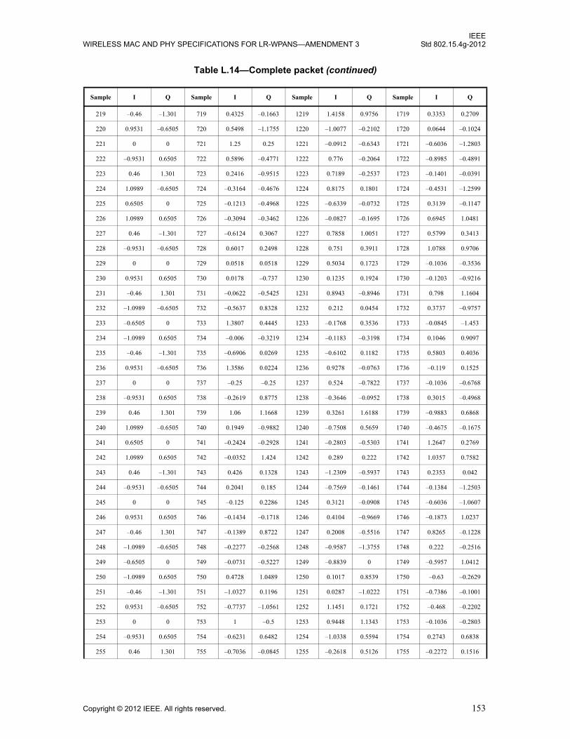
IEEEWIRELESS MAC AND PHY SPECIFICATIONS FOR LR-WPANS—AMENDMENT 3 Std 802.15.4g-2012
219 –0.46 –1.301 719 0.4325 –0.1663 1219 1.4158 0.9756 1719 0.3353 0.2709
220 0.9531 –0.6505 720 0.5498 –1.1755 1220 –1.0077 –0.2102 1720 0.0644 –0.1024
221 0 0 721 1.25 0.25 1221 –0.0912 –0.6343 1721 –0.6036 –1.2803
222 –0.9531 0.6505 722 0.5896 –0.4771 1222 0.776 –0.2064 1722 –0.8985 –0.4891
223 0.46 1.301 723 0.2416 –0.9515 1223 0.7189 –0.2537 1723 –0.1401 –0.0391
224 1.0989 –0.6505 724 –0.3164 –0.4676 1224 0.8175 0.1801 1724 –0.4531 –1.2599
225 0.6505 0 725 –0.1213 –0.4968 1225 –0.6339 –0.0732 1725 0.3139 –0.1147
226 1.0989 0.6505 726 –0.3094 –0.3462 1226 –0.0827 –0.1695 1726 0.6945 1.0481
227 0.46 –1.301 727 –0.6124 0.3067 1227 0.7858 1.0051 1727 0.5799 0.3413
228 –0.9531 –0.6505 728 0.6017 0.2498 1228 0.751 0.3911 1728 1.0788 0.9706
229 0 0 729 0.0518 0.0518 1229 0.5034 0.1723 1729 –0.1036 –0.3536
230 0.9531 0.6505 730 0.0178 –0.737 1230 0.1235 0.1924 1730 –0.1203 –0.9216
231 –0.46 1.301 731 –0.0622 –0.5425 1231 0.8943 –0.8946 1731 0.798 1.1604
232 –1.0989 –0.6505 732 –0.5637 0.8328 1232 0.212 0.0454 1732 0.3737 –0.9757
233 –0.6505 0 733 1.3807 0.4445 1233 –0.1768 0.3536 1733 –0.0845 –1.453
234 –1.0989 0.6505 734 –0.006 –0.3219 1234 –0.1183 –0.3198 1734 0.1046 0.9097
235 –0.46 –1.301 735 –0.6906 0.0269 1235 –0.6102 0.1182 1735 0.5803 0.4036
236 0.9531 –0.6505 736 1.3586 0.0224 1236 0.9278 –0.0763 1736 –0.119 0.1525
237 0 0 737 –0.25 –0.25 1237 0.524 –0.7822 1737 –0.1036 –0.6768
238 –0.9531 0.6505 738 –0.2619 0.8775 1238 –0.3646 –0.0952 1738 0.3015 –0.4968
239 0.46 1.301 739 1.06 1.1668 1239 0.3261 1.6188 1739 –0.9883 0.6868
240 1.0989 –0.6505 740 0.1949 –0.9882 1240 –0.7508 0.5659 1740 –0.4675 –0.1675
241 0.6505 0 741 –0.2424 –0.2928 1241 –0.2803 –0.5303 1741 1.2647 0.2769
242 1.0989 0.6505 742 –0.0352 1.424 1242 0.289 0.222 1742 1.0357 0.7582
243 0.46 –1.301 743 0.426 0.1328 1243 –1.2309 –0.5937 1743 0.2353 0.042
244 –0.9531 –0.6505 744 0.2041 0.185 1244 –0.7569 –0.1461 1744 –0.1384 –1.2503
245 0 0 745 –0.125 0.2286 1245 0.3121 –0.0908 1745 –0.6036 –1.0607
246 0.9531 0.6505 746 –0.1434 –0.1718 1246 0.4104 –0.9669 1746 –0.1873 1.0237
247 –0.46 1.301 747 –0.1389 0.8722 1247 0.2008 –0.5516 1747 0.8265 –0.1228
248 –1.0989 –0.6505 748 –0.2277 –0.2568 1248 –0.9587 –1.3755 1748 0.222 –0.2516
249 –0.6505 0 749 –0.0731 –0.5227 1249 –0.8839 0 1749 –0.5957 1.0412
250 –1.0989 0.6505 750 0.4728 1.0489 1250 0.1017 0.8539 1750 –0.63 –0.2629
251 –0.46 –1.301 751 –1.0327 0.1196 1251 0.0287 –1.0222 1751 –0.7386 –0.1001
252 0.9531 –0.6505 752 –0.7737 –1.0561 1252 1.1451 0.1721 1752 –0.468 –0.2202
253 0 0 753 1 –0.5 1253 0.9448 1.1343 1753 –0.1036 –0.2803
254 –0.9531 0.6505 754 –0.6231 0.6482 1254 –1.0338 0.5594 1754 0.2743 0.6838
255 0.46 1.301 755 –0.7036 –0.0845 1255 –0.2618 0.5126 1755 –0.2272 0.1516
Table L.14—Complete packet (continued)
Sample I Q Sample I Q Sample I Q Sample I Q
Copyright © 2012 IEEE. All rights reserved. 153

IEEEStd 802.15.4g-2012 LOCAL AND METROPOLITAN AREA NETWORKS—PART 15.4:
256 1.0989 –0.6505 756 0.2741 –1.1065 1256 –0.4757 0.5893 1756 –0.5012 0.4163
257 0.6505 0 757 –0.3358 0.1004 1257 –1.1339 0.4268 1757 0.3932 –0.3853
258 1.0989 0.6505 758 –0.3413 –0.6247 1258 0.231 –0.3677 1758 0.1315 –1.2505
259 0.46 –1.301 759 0.0041 –1.0841 1259 0.0001 0.5604 1759 –0.5593 0.524
260 –0.9531 –0.6505 760 0.4098 0.3478 1260 0.079 0.5031 1760 –0.7824 0.5917
261 0 0 761 –0.3018 –0.3018 1261 –0.1499 –0.6723 1761 –1.4874 0.3536
262 0.9531 0.6505 762 –0.3041 –0.3038 1262 –0.879 0.3107 1762 –0.8989 0.4187
263 –0.46 1.301 763 0.2536 –0.6519 1263 0.0628 0.3068 1763 0.2643 –0.3137
264 –1.0989 –0.6505 764 0.1863 –1.3532 1264 0.1529 0.2583 1764 –0.5084 0.1167
265 –0.6505 0 765 0.7835 0.6591 1265 0.5303 0.7071 1765 –1.0687 0.403
266 –1.0989 0.6505 766 –0.1615 1.0382 1266 0.5446 –0.1371 1766 0.4622 –0.2318
267 –0.46 –1.301 767 –0.3543 0.444 1267 –0.3343 –0.8645 1767 –0.2149 0.7697
268 0.9531 –0.6505 768 –0.2568 0.0816 1268 –0.2946 –1.1975 1768 0.2876 0.3284
269 0 0 769 –1.5 –1 1269 –0.6705 –1.132 1769 0.9786 0.4482
270 –0.9531 0.6505 770 –0.8579 –0.0613 1270 –0.1481 –1.0283 1770 –0.2033 0.4965
271 0.46 1.301 771 –0.5981 –0.1308 1271 0.131 0.3293 1771 0.1658 –1.2037
272 1.0989 –0.6505 772 0.2936 –1.3118 1272 –0.7444 1.1245 1772 0.3518 –0.0415
273 0.6505 0 773 1.1995 –0.8108 1273 –0.7803 –0.5303 1773 0.5608 0.7043
274 1.0989 0.6505 774 –0.0847 –0.282 1274 –0.5906 0.1619 1774 0.1553 0.1143
275 0.46 –1.301 775 –0.1105 0.9376 1275 –0.055 1.2353 1775 –0.9012 0.4369
276 –0.9531 –0.6505 776 –0.279 0.9434 1276 0.1562 –0.4363 1776 0.328 –0.1142
277 0 0 777 –0.125 –0.4786 1277 0.0415 –0.8234 1777 0.9571 –0.1768
278 0.9531 0.6505 778 0.583 –0.1889 1278 0.1156 0.2344 1778 0.0343 0.6611
279 –0.46 1.301 779 –0.0524 0.3223 1279 0.7563 0.3465 1779 0.132 0.6966
280 –1.0989 –0.6505 780 –0.2553 0.8228 1280 0.7471 –0.388 1780 0.6536 –0.5701
281 –0.6505 0 781 –0.5911 0.9192 1281 0.1768 –0.1768 1781 0.2659 –0.4157
282 –1.0989 0.6505 782 –0.5347 0.4778 1282 1.1994 –0.1394 1782 –0.2429 0.4121
283 –0.46 –1.301 783 0.3705 1.1166 1283 0.7883 –0.8558 1783 –0.6262 –0.9135
284 0.9531 –0.6505 784 1.1496 1.0545 1284 0.1254 0.2224 1784 –0.4221 –0.1994
285 0 0 785 1.25 0.25 1285 0.4199 0.2061 1785 0.8321 0.8018
286 –0.9531 0.6505 786 0.5896 –0.4771 1286 –0.3473 –0.5966 1786 –0.1098 –0.7883
287 0.46 1.301 787 0.2416 –0.9515 1287 –0.5288 0.0012 1787 –1.0394 –0.4287
288 1.0989 –0.6505 788 –0.3164 –0.4676 1288 0.125 –0.0038 1788 0.2617 0.396
289 –0.6505 0 789 –0.1213 –0.4968 1289 0.6036 0.0732 1789 –0.0032 0.0409
290 –1.0989 –0.6505 790 –0.3094 –0.3462 1290 0.5678 0.2475 1790 –0.1526 0.7973
291 –0.46 1.301 791 –0.6124 0.3067 1291 –0.2018 –0.1097 1791 –0.4093 0.7031
292 0.9531 0.6505 792 0.6017 0.2498 1292 –1.002 0.4166 1792 –1.1569 –0.862
Table L.14—Complete packet (continued)
Sample I Q Sample I Q Sample I Q Sample I Q
154 Copyright © 2012 IEEE. All rights reserved.
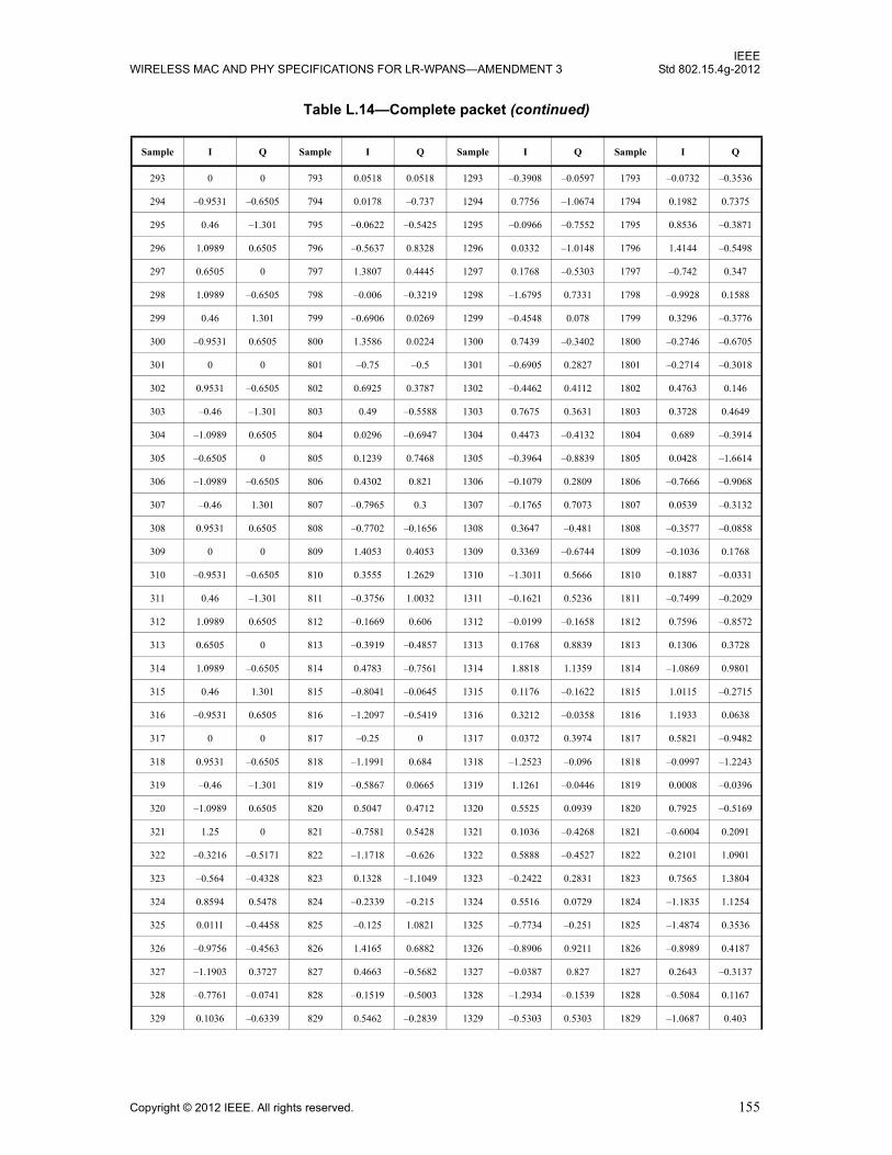
IEEEWIRELESS MAC AND PHY SPECIFICATIONS FOR LR-WPANS—AMENDMENT 3 Std 802.15.4g-2012
293 0 0 793 0.0518 0.0518 1293 –0.3908 –0.0597 1793 –0.0732 –0.3536
294 –0.9531 –0.6505 794 0.0178 –0.737 1294 0.7756 –1.0674 1794 0.1982 0.7375
295 0.46 –1.301 795 –0.0622 –0.5425 1295 –0.0966 –0.7552 1795 0.8536 –0.3871
296 1.0989 0.6505 796 –0.5637 0.8328 1296 0.0332 –1.0148 1796 1.4144 –0.5498
297 0.6505 0 797 1.3807 0.4445 1297 0.1768 –0.5303 1797 –0.742 0.347
298 1.0989 –0.6505 798 –0.006 –0.3219 1298 –1.6795 0.7331 1798 –0.9928 0.1588
299 0.46 1.301 799 –0.6906 0.0269 1299 –0.4548 0.078 1799 0.3296 –0.3776
300 –0.9531 0.6505 800 1.3586 0.0224 1300 0.7439 –0.3402 1800 –0.2746 –0.6705
301 0 0 801 –0.75 –0.5 1301 –0.6905 0.2827 1801 –0.2714 –0.3018
302 0.9531 –0.6505 802 0.6925 0.3787 1302 –0.4462 0.4112 1802 0.4763 0.146
303 –0.46 –1.301 803 0.49 –0.5588 1303 0.7675 0.3631 1803 0.3728 0.4649
304 –1.0989 0.6505 804 0.0296 –0.6947 1304 0.4473 –0.4132 1804 0.689 –0.3914
305 –0.6505 0 805 0.1239 0.7468 1305 –0.3964 –0.8839 1805 0.0428 –1.6614
306 –1.0989 –0.6505 806 0.4302 0.821 1306 –0.1079 0.2809 1806 –0.7666 –0.9068
307 –0.46 1.301 807 –0.7965 0.3 1307 –0.1765 0.7073 1807 0.0539 –0.3132
308 0.9531 0.6505 808 –0.7702 –0.1656 1308 0.3647 –0.481 1808 –0.3577 –0.0858
309 0 0 809 1.4053 0.4053 1309 0.3369 –0.6744 1809 –0.1036 0.1768
310 –0.9531 –0.6505 810 0.3555 1.2629 1310 –1.3011 0.5666 1810 0.1887 –0.0331
311 0.46 –1.301 811 –0.3756 1.0032 1311 –0.1621 0.5236 1811 –0.7499 –0.2029
312 1.0989 0.6505 812 –0.1669 0.606 1312 –0.0199 –0.1658 1812 0.7596 –0.8572
313 0.6505 0 813 –0.3919 –0.4857 1313 0.1768 0.8839 1813 0.1306 0.3728
314 1.0989 –0.6505 814 0.4783 –0.7561 1314 1.8818 1.1359 1814 –1.0869 0.9801
315 0.46 1.301 815 –0.8041 –0.0645 1315 0.1176 –0.1622 1815 1.0115 –0.2715
316 –0.9531 0.6505 816 –1.2097 –0.5419 1316 0.3212 –0.0358 1816 1.1933 0.0638
317 0 0 817 –0.25 0 1317 0.0372 0.3974 1817 0.5821 –0.9482
318 0.9531 –0.6505 818 –1.1991 0.684 1318 –1.2523 –0.096 1818 –0.0997 –1.2243
319 –0.46 –1.301 819 –0.5867 0.0665 1319 1.1261 –0.0446 1819 0.0008 –0.0396
320 –1.0989 0.6505 820 0.5047 0.4712 1320 0.5525 0.0939 1820 0.7925 –0.5169
321 1.25 0 821 –0.7581 0.5428 1321 0.1036 –0.4268 1821 –0.6004 0.2091
322 –0.3216 –0.5171 822 –1.1718 –0.626 1322 0.5888 –0.4527 1822 0.2101 1.0901
323 –0.564 –0.4328 823 0.1328 –1.1049 1323 –0.2422 0.2831 1823 0.7565 1.3804
324 0.8594 0.5478 824 –0.2339 –0.215 1324 0.5516 0.0729 1824 –1.1835 1.1254
325 0.0111 –0.4458 825 –0.125 1.0821 1325 –0.7734 –0.251 1825 –1.4874 0.3536
326 –0.9756 –0.4563 826 1.4165 0.6882 1326 –0.8906 0.9211 1826 –0.8989 0.4187
327 –1.1903 0.3727 827 0.4663 –0.5682 1327 –0.0387 0.827 1827 0.2643 –0.3137
328 –0.7761 –0.0741 828 –0.1519 –0.5003 1328 –1.2934 –0.1539 1828 –0.5084 0.1167
329 0.1036 –0.6339 829 0.5462 –0.2839 1329 –0.5303 0.5303 1829 –1.0687 0.403
Table L.14—Complete packet (continued)
Sample I Q Sample I Q Sample I Q Sample I Q
Copyright © 2012 IEEE. All rights reserved. 155
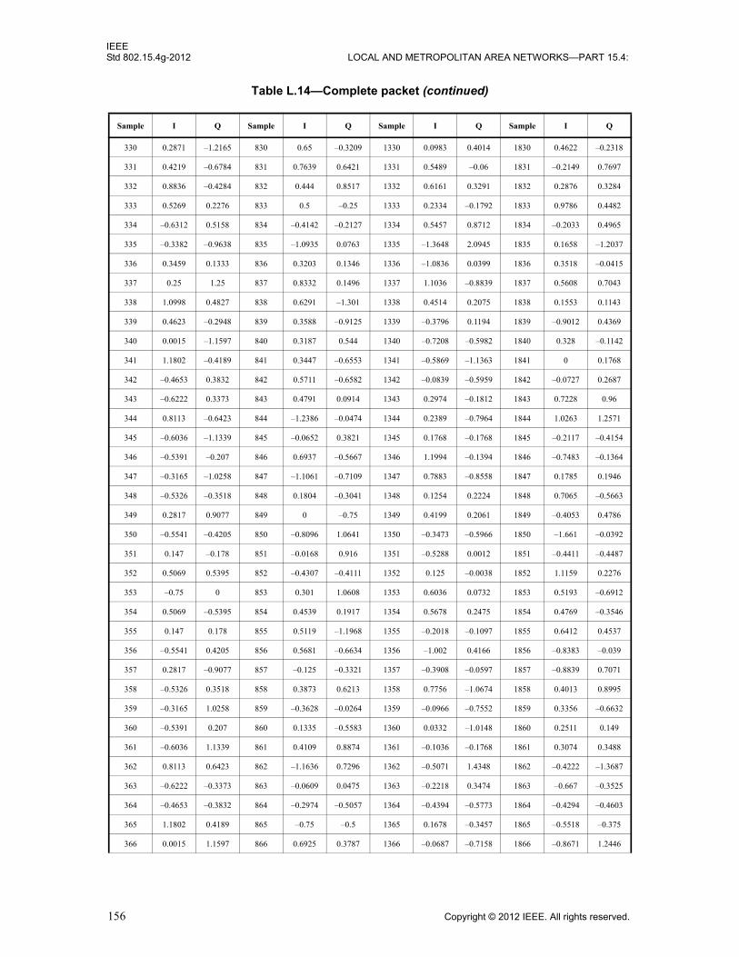
IEEEStd 802.15.4g-2012 LOCAL AND METROPOLITAN AREA NETWORKS—PART 15.4:
330 0.2871 –1.2165 830 0.65 –0.3209 1330 0.0983 0.4014 1830 0.4622 –0.2318
331 0.4219 –0.6784 831 0.7639 0.6421 1331 0.5489 –0.06 1831 –0.2149 0.7697
332 0.8836 –0.4284 832 0.444 0.8517 1332 0.6161 0.3291 1832 0.2876 0.3284
333 0.5269 0.2276 833 0.5 –0.25 1333 0.2334 –0.1792 1833 0.9786 0.4482
334 –0.6312 0.5158 834 –0.4142 –0.2127 1334 0.5457 0.8712 1834 –0.2033 0.4965
335 –0.3382 –0.9638 835 –1.0935 0.0763 1335 –1.3648 2.0945 1835 0.1658 –1.2037
336 0.3459 0.1333 836 0.3203 0.1346 1336 –1.0836 0.0399 1836 0.3518 –0.0415
337 0.25 1.25 837 0.8332 0.1496 1337 1.1036 –0.8839 1837 0.5608 0.7043
338 1.0998 0.4827 838 0.6291 –1.301 1338 0.4514 0.2075 1838 0.1553 0.1143
339 0.4623 –0.2948 839 0.3588 –0.9125 1339 –0.3796 0.1194 1839 –0.9012 0.4369
340 0.0015 –1.1597 840 0.3187 0.544 1340 –0.7208 –0.5982 1840 0.328 –0.1142
341 1.1802 –0.4189 841 0.3447 –0.6553 1341 –0.5869 –1.1363 1841 0 0.1768
342 –0.4653 0.3832 842 0.5711 –0.6582 1342 –0.0839 –0.5959 1842 –0.0727 0.2687
343 –0.6222 0.3373 843 0.4791 0.0914 1343 0.2974 –0.1812 1843 0.7228 0.96
344 0.8113 –0.6423 844 –1.2386 –0.0474 1344 0.2389 –0.7964 1844 1.0263 1.2571
345 –0.6036 –1.1339 845 –0.0652 0.3821 1345 0.1768 –0.1768 1845 –0.2117 –0.4154
346 –0.5391 –0.207 846 0.6937 –0.5667 1346 1.1994 –0.1394 1846 –0.7483 –0.1364
347 –0.3165 –1.0258 847 –1.1061 –0.7109 1347 0.7883 –0.8558 1847 0.1785 0.1946
348 –0.5326 –0.3518 848 0.1804 –0.3041 1348 0.1254 0.2224 1848 0.7065 –0.5663
349 0.2817 0.9077 849 0 –0.75 1349 0.4199 0.2061 1849 –0.4053 0.4786
350 –0.5541 –0.4205 850 –0.8096 1.0641 1350 –0.3473 –0.5966 1850 –1.661 –0.0392
351 0.147 –0.178 851 –0.0168 0.916 1351 –0.5288 0.0012 1851 –0.4411 –0.4487
352 0.5069 0.5395 852 –0.4307 –0.4111 1352 0.125 –0.0038 1852 1.1159 0.2276
353 –0.75 0 853 0.301 1.0608 1353 0.6036 0.0732 1853 0.5193 –0.6912
354 0.5069 –0.5395 854 0.4539 0.1917 1354 0.5678 0.2475 1854 0.4769 –0.3546
355 0.147 0.178 855 0.5119 –1.1968 1355 –0.2018 –0.1097 1855 0.6412 0.4537
356 –0.5541 0.4205 856 0.5681 –0.6634 1356 –1.002 0.4166 1856 –0.8383 –0.039
357 0.2817 –0.9077 857 –0.125 –0.3321 1357 –0.3908 –0.0597 1857 –0.8839 0.7071
358 –0.5326 0.3518 858 0.3873 0.6213 1358 0.7756 –1.0674 1858 0.4013 0.8995
359 –0.3165 1.0258 859 –0.3628 –0.0264 1359 –0.0966 –0.7552 1859 0.3356 –0.6632
360 –0.5391 0.207 860 0.1335 –0.5583 1360 0.0332 –1.0148 1860 0.2511 0.149
361 –0.6036 1.1339 861 0.4109 0.8874 1361 –0.1036 –0.1768 1861 0.3074 0.3488
362 0.8113 0.6423 862 –1.1636 0.7296 1362 –0.5071 1.4348 1862 –0.4222 –1.3687
363 –0.6222 –0.3373 863 –0.0609 0.0475 1363 –0.2218 0.3474 1863 –0.667 –0.3525
364 –0.4653 –0.3832 864 –0.2974 –0.5057 1364 –0.4394 –0.5773 1864 –0.4294 –0.4603
365 1.1802 0.4189 865 –0.75 –0.5 1365 0.1678 –0.3457 1865 –0.5518 –0.375
366 0.0015 1.1597 866 0.6925 0.3787 1366 –0.0687 –0.7158 1866 –0.8671 1.2446
Table L.14—Complete packet (continued)
Sample I Q Sample I Q Sample I Q Sample I Q
156 Copyright © 2012 IEEE. All rights reserved.

IEEEWIRELESS MAC AND PHY SPECIFICATIONS FOR LR-WPANS—AMENDMENT 3 Std 802.15.4g-2012
367 0.4623 0.2948 867 0.49 –0.5588 1367 0.1659 –0.3205 1867 –0.8479 –0.3663
368 1.0998 –0.4827 868 0.0296 –0.6947 1368 0.4969 –0.1672 1868 –0.3676 –1.0043
369 0.25 –1.25 869 0.1239 0.7468 1369 –0.2803 0.0732 1869 –0.153 –0.4651
370 0.3459 –0.1333 870 0.4302 0.821 1370 –0.4692 0.361 1870 0.4652 0.0878
371 –0.3382 0.9638 871 –0.7965 0.3 1371 –0.5611 –0.1364 1871 1.4612 0.7954
372 –0.6312 –0.5158 872 –0.7702 –0.1656 1372 –0.4332 –0.3624 1872 0.6684 0.2049
373 0.5269 –0.2276 873 1.4053 0.4053 1373 0.4743 –0.5845 1873 0 0.8839
374 0.8836 0.4284 874 0.3555 1.2629 1374 0.4699 –0.1637 1874 1.0586 –0.3127
375 0.4219 0.6784 875 –0.3756 1.0032 1375 –0.4154 –0.188 1875 0.2661 –0.7956
376 0.2871 1.2165 876 –0.1669 0.606 1376 –0.1374 –0.3935 1876 –1.3694 0.2729
377 0.1036 0.6339 877 –0.3919 –0.4857 1377 –0.25 0.5303 1877 –0.5383 –1.3953
378 –0.7761 0.0741 878 0.4783 –0.7561 1378 –0.8872 0.0904 1878 0.399 0.2903
379 –1.1903 –0.3727 879 –0.8041 –0.0645 1379 0.1095 –0.6144 1879 0.2723 0.6389
380 –0.9756 0.4563 880 –1.2097 –0.5419 1380 0.1946 –0.3511 1880 0.0775 –1.3992
381 0.0111 0.4458 881 0 0 1381 –0.0558 0.1274 1881 –0.6553 0.2286
382 0.8594 –0.5478 882 –0.7224 –1.061 1382 0.7378 1.0306 1882 –0.7675 0.0927
383 –0.564 0.4328 883 0.0986 –0.2501 1383 0.1524 0.7855 1883 0.2387 –0.1194
384 –0.3216 0.5171 884 –0.6047 1.2378 1384 –0.7686 –0.1897 1884 0.5741 –0.1968
385 1.25 0 885 –0.3547 –0.028 1385 –1.0303 –0.0732 1885 –0.2693 –0.8265
386 –0.3216 –0.5171 886 0.4239 –0.645 1386 –0.9171 0.8333 1886 –1.3383 0.3229
387 –0.564 –0.4328 887 0.3278 –0.6477 1387 –0.3681 1.1834 1887 –1.2295 –0.1181
388 0.8594 0.5478 888 –0.3022 –0.2338 1388 –0.1581 0.2614 1888 –0.4267 0.1254
389 0.0111 –0.4458 889 0.4053 1.0089 1389 –0.6118 –0.6114 1889 –0.5303 0.3536
390 –0.9756 –0.4563 890 1.3666 0.6059 1390 –0.1488 0.3559 1890 –0.3639 –0.3556
391 –1.1903 0.3727 891 0.1337 –0.0563 1391 1.1808 0.7177 1891 0.3827 –0.2084
392 –0.7761 –0.0741 892 0.882 –0.3037 1392 0.3623 –1.1271 1892 0.3752 –0.6378
393 0.1036 –0.6339 893 0.4167 –0.2635 1393 0.25 –0.8839 1893 0.4426 0.7547
394 0.2871 –1.2165 894 –0.7497 –0.0026 1394 1.396 –0.5758 1894 0.4059 0.7148
395 0.4219 –0.6784 895 0.8389 –1.3511 1395 0.1183 –1.1766 1895 –0.0767 –0.7739
396 0.8836 –0.4284 896 –0.0407 –1.4127 1396 –1.0588 0.6119 1896 0.2352 0.6192
397 0.5269 0.2276 897 0.75 0.25 1397 –1.5214 –0.1543 1897 0.1982 0.375
398 –0.6312 0.5158 898 1.3445 0.4739 1398 –0.3341 –0.3884 1898 –0.142 –0.7982
399 –0.3382 –0.9638 899 –0.8199 0.3431 1399 0.9788 1.7396 1899 0.7575 0.2273
400 0.3459 0.1333 900 –0.0429 0.0252 1400 –0.6621 –0.1632 1900 0.8086 0.9322
401 0.25 1.25 901 –0.5296 –0.3943 1401 –0.7803 –0.9268 1901 –0.097 –0.1385
402 1.0998 0.4827 902 –0.1959 –0.2655 1402 –0.8951 0.2553 1902 0.3477 –0.5561
403 0.4623 –0.2948 903 0.7708 –0.1596 1403 –0.9663 0.1538 1903 0.8342 0.5761
Table L.14—Complete packet (continued)
Sample I Q Sample I Q Sample I Q Sample I Q
Copyright © 2012 IEEE. All rights reserved. 157

IEEEStd 802.15.4g-2012 LOCAL AND METROPOLITAN AREA NETWORKS—PART 15.4:
404 0.0015 –1.1597 904 –1.1196 0.2988 1404 0.9929 0.0152 1904 0.421 0.5152
405 1.1802 –0.4189 905 0.4786 0.2286 1405 0.5864 –0.1226 1905 0 0.1768
406 –0.4653 0.3832 906 1.8203 –0.2119 1406 0.0592 0.814 1906 –0.0727 0.2687
407 –0.6222 0.3373 907 0.0559 0.1768 1407 –0.4049 –0.4701 1907 0.7228 0.96
408 0.8113 –0.6423 908 –0.7192 0.4991 1408 –0.8584 –1.1959 1908 1.0263 1.2571
409 –0.6036 –1.1339 909 –0.6297 –0.1409 1409 0.8107 0.5303 1909 –0.2117 –0.4154
410 –0.5391 –0.207 910 0.2035 –0.9139 1410 0.5755 –0.5129 1910 –0.7483 –0.1364
411 –0.3165 –1.0258 911 –0.3151 0.0227 1411 –0.213 –0.0564 1911 0.1785 0.1946
412 –0.5326 –0.3518 912 –1.3792 0.8238 1412 0.6503 0.7214 1912 0.7065 –0.5663
413 0.2817 0.9077 913 –0.25 0.25 1413 1.4093 –0.3345 1913 –0.4053 0.4786
414 –0.5541 –0.4205 914 0.6563 0.5325 1414 0.7772 0.1274 1914 –1.661 –0.0392
415 0.147 –0.178 915 –0.3756 0.2564 1415 –0.0901 –0.2903 1915 –0.4411 –0.4487
416 0.5069 0.5395 916 –0.6222 –0.3347 1416 0.6632 0.3901 1916 1.1159 0.2276
417 –0.75 0 917 0.3547 0.028 1417 –0.0303 0.9268 1917 0.5193 –0.6912
418 0.5069 –0.5395 918 –0.1308 0.2017 1418 –0.2958 –0.4719 1918 0.4769 –0.3546
419 0.147 0.178 919 –0.7871 1.1608 1419 0.6884 0.2991 1919 0.6412 0.4537
420 –0.5541 0.4205 920 –0.7915 0.6192 1420 0.2517 0.2667 1920 –0.8383 –0.039
421 0.2817 –0.9077 921 –0.6553 –0.7589 1421 0.9654 –0.8028 1921 –0.1768 0.7071
422 –0.5326 0.3518 922 –0.3077 0.685 1422 0.5076 0.3542 1922 0.0188 0.0162
423 –0.3165 1.0258 923 0.1051 0.4707 1423 –0.1534 0.8546 1923 –0.0149 0.0996
424 –0.5391 0.207 924 0.765 –1.2526 1424 0.9041 –0.5678 1924 0.0536 0.6254
425 –0.6036 1.1339 925 –0.5632 –0.5901 1425 –0.1036 –0.1768 1925 1.2606 0.0549
426 0.8113 0.6423 926 –0.9437 –0.1152 1426 –0.5071 1.4348 1926 0.5406 –0.1999
427 –0.6222 –0.3373 927 0.4703 –0.3946 1427 –0.2218 0.3474 1927 –0.6483 0.1982
428 –0.4653 –0.3832 928 –0.1704 –0.2313 1428 –0.4394 –0.5773 1928 0.4289 –1.1884
429 1.1802 0.4189 929 0.5 0.5 1429 0.1678 –0.3457 1929 –0.0214 –0.8018
430 0.0015 1.1597 930 0.8652 1.0323 1430 –0.0687 –0.7158 1930 0.2803 0.4548
431 0.4623 0.2948 931 –0.1102 0.8577 1431 0.1659 –0.3205 1931 0.7002 –0.3675
432 1.0998 –0.4827 932 0.7064 1.19 1432 0.4969 –0.1672 1932 –1.0376 –0.2012
433 0.25 –1.25 933 0.5296 0.3943 1433 –0.2803 0.0732 1933 –0.8039 –0.074
434 0.3459 –0.1333 934 0.1419 –0.6515 1434 –0.4692 0.361 1934 –0.3884 0.1453
435 –0.3382 0.9638 935 0.1885 0.5606 1435 –0.5611 –0.1364 1935 –0.6539 0.3117
436 –0.6312 –0.5158 936 –0.1471 0.7344 1436 –0.4332 –0.3624 1936 –1.1651 –1.1555
437 0.5269 –0.2276 937 –0.2286 –0.4786 1437 0.4743 –0.5845 1937 –1.7678 –0.8839
438 0.8836 0.4284 938 –0.1944 –0.6425 1438 0.4699 –0.1637 1938 –0.7176 0.0897
439 0.4219 0.6784 939 –0.0877 –0.7983 1439 –0.4154 –0.188 1939 0.1292 –0.3738
440 0.2871 1.2165 940 –0.95 –1.0612 1440 –0.1374 –0.3935 1940 0.8451 –0.1536
Table L.14—Complete packet (continued)
Sample I Q Sample I Q Sample I Q Sample I Q
158 Copyright © 2012 IEEE. All rights reserved.

IEEEWIRELESS MAC AND PHY SPECIFICATIONS FOR LR-WPANS—AMENDMENT 3 Std 802.15.4g-2012
441 0.1036 0.6339 941 –0.2238 –0.0056 1441 0.0732 0.7071 1941 –0.0497 0.0946
442 –0.7761 0.0741 942 0.4224 0.9778 1442 –0.1505 0.1106 1942 –0.8163 –0.3697
443 –1.1903 –0.3727 943 –0.494 –0.1912 1443 0.7487 –0.2539 1943 0.712 –0.1527
444 –0.9756 0.4563 944 0.5364 –0.5984 1444 0.5702 –0.3195 1944 –0.2692 0.0432
445 0.0111 0.4458 945 0 0 1445 0.2407 –0.4889 1945 –0.4786 –0.1982
446 0.8594 –0.5478 946 –0.7224 –1.061 1446 1.4049 0.235 1946 0.9743 –0.3294
447 –0.564 0.4328 947 0.0986 –0.2501 1447 0.267 0.8823 1947 0.9417 –0.7351
448 –0.3216 0.5171 948 –0.6047 1.2378 1448 –0.1098 0.5457 1948 0.5535 –0.3754
449 1.25 0 949 –0.3547 –0.028 1449 0 0.4571 1949 –1.1141 –0.4582
450 –0.3216 –0.5171 950 0.4239 –0.645 1450 –1.0648 0.1166 1950 –0.3284 –0.1895
451 –0.564 –0.4328 951 0.3278 –0.6477 1451 –0.1968 0.4275 1951 0.7145 1.911
452 0.8594 0.5478 952 –0.3022 –0.2338 1452 –0.2262 0.5005 1952 –1.0893 0.7769
453 0.0111 –0.4458 953 0.4053 1.0089 1453 –0.1371 –0.9889 1953 0.1768 –0.3536
454 –0.9756 –0.4563 954 1.3666 0.6059 1454 0.9962 –0.8207 1954 1.2181 0.7631
455 –1.1903 0.3727 955 0.1337 –0.0563 1455 0.7019 0.0296 1955 –0.4021 –0.3447
456 –0.7761 –0.0741 956 0.882 –0.3037 1456 –0.2743 0.2598 1956 –0.923 0.2865
457 0.1036 –0.6339 957 0.4167 –0.2635 1457 –0.7803 0.3536 1957 –0.2606 0.6522
458 0.2871 –1.2165 958 –0.7497 –0.0026 1458 0.2517 –0.5182 1958 0.692 –0.9556
459 0.4219 –0.6784 959 0.8389 –1.3511 1459 –0.5378 –0.1761 1959 0.3486 –0.0292
460 0.8836 –0.4284 960 –0.0407 –1.4127 1460 –1.694 –0.1293 1960 0.3173 0.7422
461 0.5269 0.2276 961 –0.8839 0.3536 1461 –0.4844 –0.6802 1961 0.7286 0.4482
462 –0.6312 0.5158 962 –0.0336 0.8687 1462 –0.9842 0.2458 1962 –0.3733 –0.2533
463 –0.3382 –0.9638 963 –0.7799 0.1728 1463 –1.1416 –0.1229 1963 –0.4999 –0.1482
464 0.3459 0.1333 964 0.1891 –0.6159 1464 –0.0986 0.3233 1964 0.0756 0.04
465 0.25 1.25 965 0.6734 –0.4006 1465 –0.25 0.6036 1965 0.0968 –1.1331
466 1.0998 0.4827 966 0.2461 0.05 1466 –0.5928 –1.5937 1966 0.9873 0.4546
467 0.4623 –0.2948 967 1.184 0.4273 1467 –0.1564 –0.3116 1967 0.7369 1.2041
468 0.0015 –1.1597 968 0.4654 0.1181 1468 0.4498 1.6195 1968 –0.7251 0.0654
469 1.1802 –0.4189 969 –1.5089 –0.125 1469 –0.0273 0.4731 1969 0.3536 0.5303
470 –0.4653 0.3832 970 –0.2443 –0.146 1470 0.5568 –0.6178 1970 1.1877 –0.4863
471 –0.6222 0.3373 971 0.7714 –0.6208 1471 0.3324 –0.8678 1971 –0.005 –0.7952
472 0.8113 –0.6423 972 –0.6118 –0.675 1472 –0.7073 0.476 1972 –0.224 0.1656
473 –0.6036 –1.1339 973 –0.8753 –0.5169 1473 0.4268 0 1973 –0.9503 0.6125
474 –0.5391 –0.207 974 –0.5449 –0.4082 1474 –0.4977 –0.9329 1974 –0.7091 0.6012
475 –0.3165 –1.0258 975 0.4193 0.2374 1475 –0.6901 1.2402 1975 0.2949 –0.6021
476 –0.5326 –0.3518 976 1.6786 0.8281 1476 0.7908 0.7534 1976 –0.8776 0.0204
477 0.2817 0.9077 977 1.4142 0.8839 1477 0.32 –0.2183 1977 –0.2286 0.5518
Table L.14—Complete packet (continued)
Sample I Q Sample I Q Sample I Q Sample I Q
Copyright © 2012 IEEE. All rights reserved. 159

IEEEStd 802.15.4g-2012 LOCAL AND METROPOLITAN AREA NETWORKS—PART 15.4:
478 –0.5541 –0.4205 978 0.5174 0.1582 1478 1.0434 0.7155 1978 0.8257 –0.2548
479 0.147 –0.178 979 0.9204 –0.7007 1479 0.4069 –0.0239 1979 0.5651 –0.1633
480 0.5069 0.5395 980 0.9337 –0.233 1480 –1.1428 0.3316 1980 1.2426 –0.3872
481 0.75 0.75 981 –1.1459 0.74 1481 0 0.4571 1981 0.407 0.2511
482 0.7478 0.8804 982 0.0935 0.3738 1482 0.7672 –0.3292 1982 –0.5633 0.5135
483 –1.8473 0.0292 983 1.4272 –0.6626 1483 0.1381 –0.0534 1983 –0.0903 –0.0125
484 –1.0324 0.3448 984 –0.8333 –0.0067 1484 –0.4874 –0.8099 1984 –0.0342 0.6959
485 0.1609 0.3108 985 –0.1553 1.0821 1485 –0.2164 –0.7183 1985 –0.1768 0.7071
486 0.1388 –0.4451 986 –0.1296 –0.1823 1486 –0.243 –0.2394 1986 0.0188 0.0162
487 –0.106 –1.0522 987 –0.6472 –1.0287 1487 –0.1813 –0.2886 1987 –0.0149 0.0996
488 –0.8661 –0.2156 988 0.8176 –0.0763 1488 –0.3657 0.4548 1988 0.0536 0.6254
489 0.125 0.8321 989 0.0201 –0.0676 1489 –1.1339 –0.3536 1989 1.2606 0.0549
490 0.1346 0.4 990 0.0225 0.0677 1490 0.3331 –0.3613 1990 0.5406 –0.1999
491 –0.5951 0.2595 991 –0.0539 0.6489 1491 0.9791 0.397 1991 –0.6483 0.1982
492 –0.1195 0.4088 992 –0.2031 0.0917 1492 0.7792 –0.7507 1992 0.4289 –1.1884
493 –0.5779 0.5428 993 0.5303 –0.3536 1493 0.6308 –0.0269 1993 –0.0214 –0.8018
494 –0.255 0.5079 994 –0.4082 –0.3206 1494 –0.9103 1.0976 1994 0.2803 0.4548
495 0.9598 0.3728 995 0.4178 0.0615 1495 –0.0323 0.0574 1995 0.7002 –0.3675
496 –0.313 1.1997 996 0.3409 0.0797 1496 0.4147 –0.264 1996 –1.0376 –0.2012
497 –1 0 997 –0.8805 –0.8065 1497 0.25 0.6036 1997 –0.8039 –0.074
498 0.6711 –1.687 998 –0.2006 –0.1009 1498 1.3681 1.0939 1998 –0.3884 0.1453
499 –0.2918 –0.4937 999 –0.0355 0.8364 1499 –0.2849 0.1445 1999 –0.6539 0.3117
500 –1.2035 –0.2092 1000 0.3413 0.0992 1500 –0.5966 –0.4497 2000 –1.1651 –1.1555
Table L.14—Complete packet (continued)
Sample I Q Sample I Q Sample I Q Sample I Q
160 Copyright © 2012 IEEE. All rights reserved.
IEEEWIRELESS MAC AND PHY SPECIFICATIONS FOR LR-WPANS—AMENDMENT 3 Std 802.15.4g-2012
Insert after new Annex L the following new annex (Annex M):
Annex M
(informative)
Example of encoding a packet for MR-OFDM PHY when PIB attribute phyOFDMInterleaving is one
M.1 Introduction
The purpose of this annex is to show an example of encoding a packet for the MR-OFDM PHY, as describedin 18.2. This example covers all the encoding details defined by this standard. The encoding illustration isoutlined in L.1.
In the description of time domain waveforms, a complex baseband signal at 666.666 ksample/s is used. Thisexample uses the 400 kb/s data rate (QPSK 1/2-rate modulation), which corresponds to OFDM Option 2 andMCS level 3, and a message of 72 octets. The OFDM Header uses the 50 kb/s data rate (BPSK 1/2-ratecoded with 4x frequency repetition), which corresponds to MCS level 0. This example also sets the PIBattribute value of phyOFDMInterleaving to one.
M.2 The message
The message being encoded is given in L.2.
M.3 Generation of the OFDM header
M.3.1 HCS and PAD bits insertion
In this example, the payload data has a size of 76 octets, and it will be encoded using QPSK modulation,1/2-rate coding (Rate field value = 3). The scrambler index will be the first one (Scrambler ID = 0).
The corresponding OFDM header, including the HCS, is represented in Table M.1.
In this configuration, 12 PAD bit are necessary. The size of the header will fill up exactly eight OFDMsymbols.
M.3.2 Convolutional encoding
After convolutional encoding of the OFDM header, the size is now doubled and the corresponding bits arerepresented in Table M.2. No puncturing is applied in this configuration.
Copyright © 2012 IEEE. All rights reserved. 161

IEEEStd 802.15.4g-2012 LOCAL AND METROPOLITAN AREA NETWORKS—PART 15.4:
Table M.1—OFDM Header
Field Name Bit # Bit Value Field Name Bit # Bit Value
Rate
1 0
HCS
23 1
2 0 24 1
3 0 25 1
4 1 26 1
5 1 27 1
RFU 6 0 28 1
Length
7 0 29 0
8 0 30 1
9 0
Tail
31 0
10 0 32 0
11 1 33 0
12 0 34 0
13 0 35 0
14 1 36 0
15 1
Pad
37 0
16 0 38 0
17 0 39 0
RFU 18 0 40 0
19 0 41 0
Scrambler 20 0 42 0
21 0 43 0
RFU 22 0 44 0
45 0
46 0
47 0
48 0
162 Copyright © 2012 IEEE. All rights reserved.
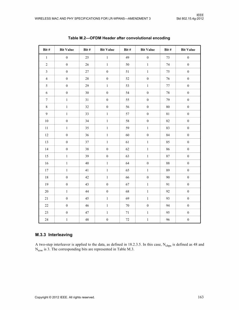
IEEEWIRELESS MAC AND PHY SPECIFICATIONS FOR LR-WPANS—AMENDMENT 3 Std 802.15.4g-2012
M.3.3 Interleaving
A two-step interleaver is applied to the data, as defined in 18.2.3.5. In this case, Ncbps is defined as 48 andNrow is 3. The corresponding bits are represented in Table M.3.
Table M.2—OFDM Header after convolutional encoding
Bit # Bit Value Bit # Bit Value Bit # Bit Value Bit # Bit Value
1 0 25 1 49 0 73 0
2 0 26 1 50 1 74 0
3 0 27 0 51 1 75 0
4 0 28 0 52 0 76 0
5 0 29 1 53 1 77 0
6 0 30 0 54 0 78 0
7 1 31 0 55 0 79 0
8 1 32 0 56 0 80 0
9 1 33 1 57 0 81 0
10 0 34 1 58 0 82 0
11 1 35 1 59 1 83 0
12 0 36 1 60 0 84 0
13 0 37 1 61 1 85 0
14 0 38 0 62 1 86 0
15 1 39 0 63 1 87 0
16 1 40 1 64 0 88 0
17 1 41 1 65 1 89 0
18 0 42 1 66 0 90 0
19 0 43 0 67 1 91 0
20 1 44 0 68 1 92 0
21 0 45 1 69 1 93 0
22 0 46 1 70 0 94 0
23 0 47 1 71 1 95 0
24 1 48 0 72 1 96 0
Copyright © 2012 IEEE. All rights reserved. 163

IEEEStd 802.15.4g-2012 LOCAL AND METROPOLITAN AREA NETWORKS—PART 15.4:
Table M.3—OFDM Header after interleaving
Bit # Bit Value Bit # Bit Value Bit # Bit Value Bit # Bit Value
1 0 25 1 49 0 73 0
2 0 26 1 50 0 74 0
3 1 27 0 51 0 75 0
4 0 28 1 52 0 76 0
5 0 29 0 53 1 77 0
6 1 30 1 54 0 78 0
7 0 31 0 55 1 79 0
8 0 32 1 56 0 80 0
9 1 33 0 57 0 81 1
10 0 34 0 58 0 82 0
11 0 35 1 59 0 83 0
12 1 36 0 60 0 84 0
13 1 37 1 61 0 85 1
14 1 38 0 62 0 86 0
15 0 39 0 63 0 87 1
16 1 40 1 64 0 88 1
17 0 41 0 65 1 89 0
18 0 42 0 66 1 90 0
19 1 43 1 67 0 91 0
20 1 44 1 68 1 92 0
21 0 45 0 69 1 93 0
22 1 46 1 70 1 94 0
23 1 47 1 71 1 95 0
24 0 48 0 72 1 96 0
164 Copyright © 2012 IEEE. All rights reserved.
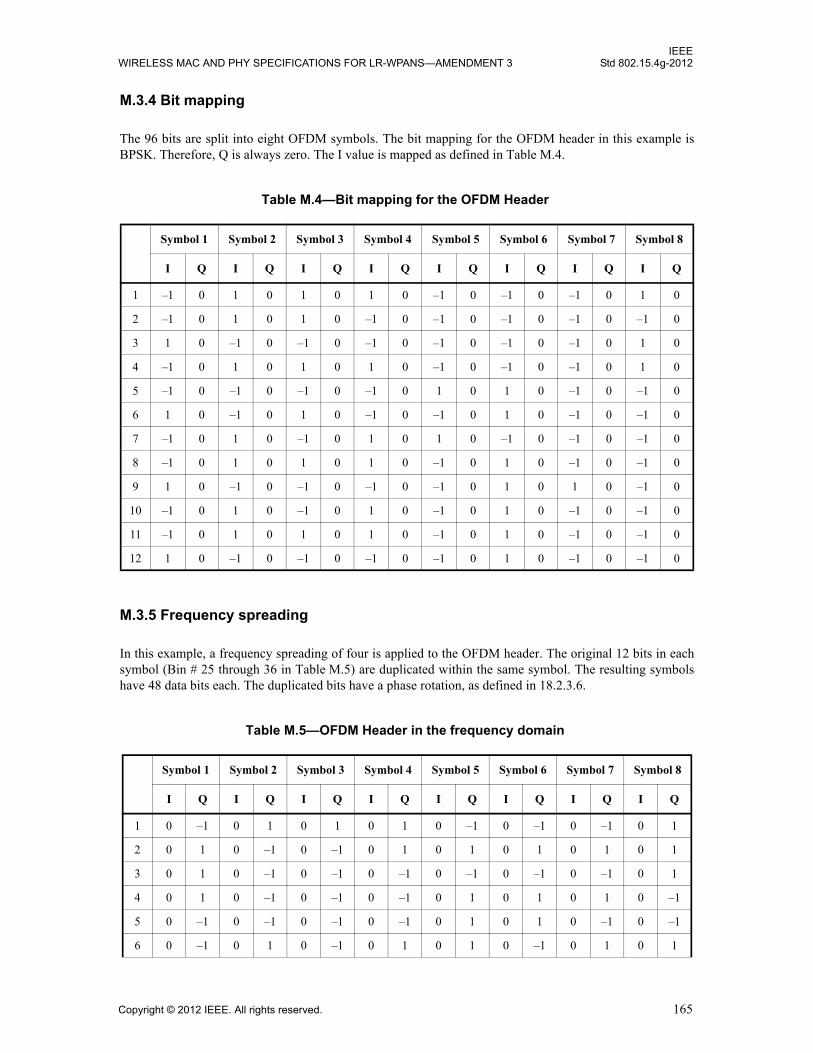
IEEEWIRELESS MAC AND PHY SPECIFICATIONS FOR LR-WPANS—AMENDMENT 3 Std 802.15.4g-2012
M.3.4 Bit mapping
The 96 bits are split into eight OFDM symbols. The bit mapping for the OFDM header in this example isBPSK. Therefore, Q is always zero. The I value is mapped as defined in Table M.4.
M.3.5 Frequency spreading
In this example, a frequency spreading of four is applied to the OFDM header. The original 12 bits in eachsymbol (Bin # 25 through 36 in Table M.5) are duplicated within the same symbol. The resulting symbolshave 48 data bits each. The duplicated bits have a phase rotation, as defined in 18.2.3.6.
Table M.4—Bit mapping for the OFDM Header
Symbol 1 Symbol 2 Symbol 3 Symbol 4 Symbol 5 Symbol 6 Symbol 7 Symbol 8
I Q I Q I Q I Q I Q I Q I Q I Q
1 –1 0 1 0 1 0 1 0 –1 0 –1 0 –1 0 1 0
2 –1 0 1 0 1 0 –1 0 –1 0 –1 0 –1 0 –1 0
3 1 0 –1 0 –1 0 –1 0 –1 0 –1 0 –1 0 1 0
4 –1 0 1 0 1 0 1 0 –1 0 –1 0 –1 0 1 0
5 –1 0 –1 0 –1 0 –1 0 1 0 1 0 –1 0 –1 0
6 1 0 –1 0 1 0 –1 0 –1 0 1 0 –1 0 –1 0
7 –1 0 1 0 –1 0 1 0 1 0 –1 0 –1 0 –1 0
8 –1 0 1 0 1 0 1 0 –1 0 1 0 –1 0 –1 0
9 1 0 –1 0 –1 0 –1 0 –1 0 1 0 1 0 –1 0
10 –1 0 1 0 –1 0 1 0 –1 0 1 0 –1 0 –1 0
11 –1 0 1 0 1 0 1 0 –1 0 1 0 –1 0 –1 0
12 1 0 –1 0 –1 0 –1 0 –1 0 1 0 –1 0 –1 0
Table M.5—OFDM Header in the frequency domain
Symbol 1 Symbol 2 Symbol 3 Symbol 4 Symbol 5 Symbol 6 Symbol 7 Symbol 8
I Q I Q I Q I Q I Q I Q I Q I Q
1 0 –1 0 1 0 1 0 1 0 –1 0 –1 0 –1 0 1
2 0 1 0 –1 0 –1 0 1 0 1 0 1 0 1 0 1
3 0 1 0 –1 0 –1 0 –1 0 –1 0 –1 0 –1 0 1
4 0 1 0 –1 0 –1 0 –1 0 1 0 1 0 1 0 –1
5 0 –1 0 –1 0 –1 0 –1 0 1 0 1 0 –1 0 –1
6 0 –1 0 1 0 –1 0 1 0 1 0 –1 0 1 0 1
Copyright © 2012 IEEE. All rights reserved. 165
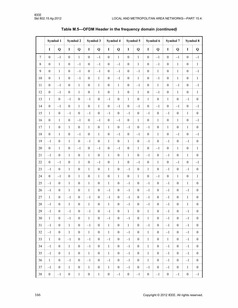
IEEEStd 802.15.4g-2012 LOCAL AND METROPOLITAN AREA NETWORKS—PART 15.4:
7 0 –1 0 1 0 –1 0 1 0 1 0 –1 0 –1 0 –1
8 0 1 0 –1 0 –1 0 –1 0 1 0 –1 0 1 0 1
9 0 1 0 –1 0 –1 0 –1 0 –1 0 1 0 1 0 –1
10 0 1 0 –1 0 1 0 –1 0 1 0 –1 0 1 0 1
11 0 –1 0 1 0 1 0 1 0 –1 0 1 0 –1 0 –1
12 0 –1 0 1 0 1 0 1 0 1 0 –1 0 1 0 1
13 1 0 –1 0 –1 0 –1 0 1 0 1 0 1 0 –1 0
14 0 –1 0 1 0 1 0 –1 0 –1 0 –1 0 –1 0 –1
15 1 0 –1 0 –1 0 –1 0 –1 0 –1 0 –1 0 1 0
16 0 1 0 –1 0 –1 0 –1 0 1 0 1 0 1 0 –1
17 1 0 1 0 1 0 1 0 –1 0 –1 0 1 0 1 0
18 0 1 0 –1 0 1 0 –1 0 –1 0 1 0 –1 0 –1
19 –1 0 1 0 –1 0 1 0 1 0 –1 0 –1 0 –1 0
20 0 1 0 –1 0 –1 0 –1 0 1 0 –1 0 1 0 1
21 –1 0 1 0 1 0 1 0 1 0 –1 0 –1 0 1 0
22 0 –1 0 1 0 –1 0 1 0 –1 0 1 0 –1 0 –1
23 –1 0 1 0 1 0 1 0 –1 0 1 0 –1 0 –1 0
24 0 –1 0 1 0 1 0 1 0 1 0 –1 0 1 0 1
25 –1 0 1 0 1 0 1 0 –1 0 –1 0 –1 0 1 0
26 –1 0 1 0 1 0 –1 0 –1 0 –1 0 –1 0 –1 0
27 1 0 –1 0 –1 0 –1 0 –1 0 –1 0 –1 0 1 0
28 –1 0 1 0 1 0 1 0 –1 0 –1 0 –1 0 1 0
29 –1 0 –1 0 –1 0 –1 0 1 0 1 0 –1 0 –1 0
30 1 0 –1 0 1 0 –1 0 –1 0 1 0 –1 0 –1 0
31 –1 0 1 0 –1 0 1 0 1 0 –1 0 –1 0 –1 0
32 –1 0 1 0 1 0 1 0 –1 0 1 0 –1 0 –1 0
33 1 0 –1 0 –1 0 –1 0 –1 0 1 0 1 0 –1 0
34 –1 0 1 0 –1 0 1 0 –1 0 1 0 –1 0 –1 0
35 –1 0 1 0 1 0 1 0 –1 0 1 0 –1 0 –1 0
36 1 0 –1 0 –1 0 –1 0 –1 0 1 0 –1 0 –1 0
37 –1 0 1 0 1 0 1 0 –1 0 –1 0 –1 0 1 0
38 0 –1 0 1 0 1 0 –1 0 –1 0 –1 0 –1 0 –1
Table M.5—OFDM Header in the frequency domain (continued)
Symbol 1 Symbol 2 Symbol 3 Symbol 4 Symbol 5 Symbol 6 Symbol 7 Symbol 8
I Q I Q I Q I Q I Q I Q I Q I Q
166 Copyright © 2012 IEEE. All rights reserved.
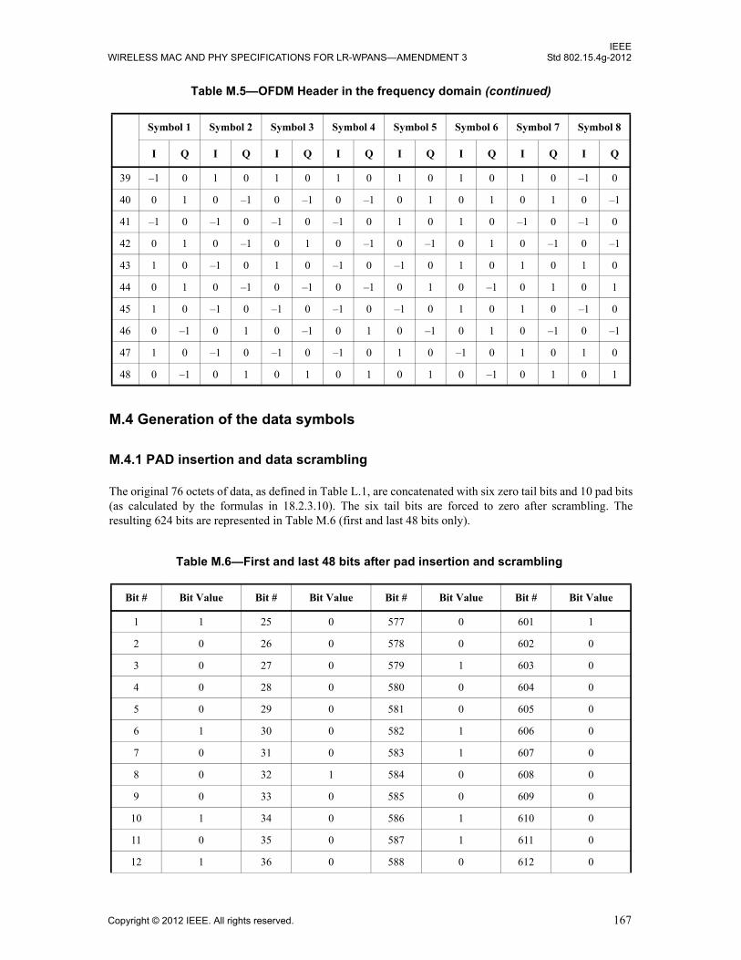
IEEEWIRELESS MAC AND PHY SPECIFICATIONS FOR LR-WPANS—AMENDMENT 3 Std 802.15.4g-2012
M.4 Generation of the data symbols
M.4.1 PAD insertion and data scrambling
The original 76 octets of data, as defined in Table L.1, are concatenated with six zero tail bits and 10 pad bits(as calculated by the formulas in 18.2.3.10). The six tail bits are forced to zero after scrambling. Theresulting 624 bits are represented in Table M.6 (first and last 48 bits only).
39 –1 0 1 0 1 0 1 0 1 0 1 0 1 0 –1 0
40 0 1 0 –1 0 –1 0 –1 0 1 0 1 0 1 0 –1
41 –1 0 –1 0 –1 0 –1 0 1 0 1 0 –1 0 –1 0
42 0 1 0 –1 0 1 0 –1 0 –1 0 1 0 –1 0 –1
43 1 0 –1 0 1 0 –1 0 –1 0 1 0 1 0 1 0
44 0 1 0 –1 0 –1 0 –1 0 1 0 –1 0 1 0 1
45 1 0 –1 0 –1 0 –1 0 –1 0 1 0 1 0 –1 0
46 0 –1 0 1 0 –1 0 1 0 –1 0 1 0 –1 0 –1
47 1 0 –1 0 –1 0 –1 0 1 0 –1 0 1 0 1 0
48 0 –1 0 1 0 1 0 1 0 1 0 –1 0 1 0 1
Table M.6—First and last 48 bits after pad insertion and scrambling
Bit # Bit Value Bit # Bit Value Bit # Bit Value Bit # Bit Value
1 1 25 0 577 0 601 1
2 0 26 0 578 0 602 0
3 0 27 0 579 1 603 0
4 0 28 0 580 0 604 0
5 0 29 0 581 0 605 0
6 1 30 0 582 1 606 0
7 0 31 0 583 1 607 0
8 0 32 1 584 0 608 0
9 0 33 0 585 0 609 0
10 1 34 0 586 1 610 0
11 0 35 0 587 1 611 0
12 1 36 0 588 0 612 0
Table M.5—OFDM Header in the frequency domain (continued)
Symbol 1 Symbol 2 Symbol 3 Symbol 4 Symbol 5 Symbol 6 Symbol 7 Symbol 8
I Q I Q I Q I Q I Q I Q I Q I Q
Copyright © 2012 IEEE. All rights reserved. 167
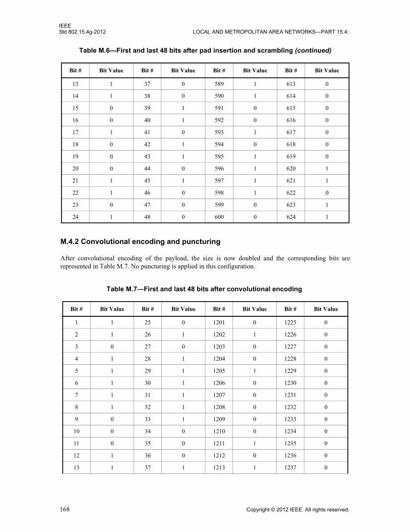
IEEEStd 802.15.4g-2012 LOCAL AND METROPOLITAN AREA NETWORKS—PART 15.4:
M.4.2 Convolutional encoding and puncturing
After convolutional encoding of the payload, the size is now doubled and the corresponding bits arerepresented in Table M.7. No puncturing is applied in this configuration.
13 1 37 0 589 1 613 0
14 1 38 0 590 1 614 0
15 0 39 1 591 0 615 0
16 0 40 1 592 0 616 0
17 1 41 0 593 1 617 0
18 0 42 1 594 0 618 0
19 0 43 1 595 1 619 0
20 0 44 0 596 1 620 1
21 1 45 1 597 1 621 1
22 1 46 0 598 1 622 0
23 0 47 0 599 0 623 1
24 1 48 0 600 0 624 1
Table M.7—First and last 48 bits after convolutional encoding
Bit # Bit Value Bit # Bit Value Bit # Bit Value Bit # Bit Value
1 1 25 0 1201 0 1225 0
2 1 26 1 1202 1 1226 0
3 0 27 0 1203 0 1227 0
4 1 28 1 1204 0 1228 0
5 1 29 1 1205 1 1229 0
6 1 30 1 1206 0 1230 0
7 1 31 1 1207 0 1231 0
8 1 32 1 1208 0 1232 0
9 0 33 1 1209 0 1233 0
10 0 34 0 1210 0 1234 0
11 0 35 0 1211 1 1235 0
12 1 36 0 1212 0 1236 0
13 1 37 1 1213 1 1237 0
Table M.6—First and last 48 bits after pad insertion and scrambling (continued)
Bit # Bit Value Bit # Bit Value Bit # Bit Value Bit # Bit Value
168 Copyright © 2012 IEEE. All rights reserved.

IEEEWIRELESS MAC AND PHY SPECIFICATIONS FOR LR-WPANS—AMENDMENT 3 Std 802.15.4g-2012
M.4.3 Interleaving
A two-step interleaver is applied to the data, as defined in 18.2.3.5. In this case, Ncbps is defined as 96 andNrow is 12. The resulting data (first and last 48 bits only) is represented in Table M.8.
14 0 38 0 1214 1 1238 0
15 1 39 0 1215 0 1239 1
16 1 40 0 1216 0 1240 1
17 1 41 1 1217 0 1241 1
18 1 42 1 1218 0 1242 0
19 1 43 0 1219 0 1243 1
20 1 44 0 1220 0 1244 0
21 1 45 0 1221 0 1245 1
22 1 46 1 1222 0 1246 1
23 1 47 1 1223 0 1247 0
24 1 48 1 1224 0 1248 1
Table M.8—First and last 48 bits after interleaving
Bit # Bit Value Bit # Bit Value Bit # Bit Value Bit # Bit Value
1 1 25 1 1201 0 1225 0
2 1 26 1 1202 0 1226 0
3 0 27 1 1203 0 1227 1
4 1 28 0 1204 0 1228 0
5 1 29 1 1205 0 1229 0
6 0 30 1 1206 0 1230 0
7 1 31 1 1207 0 1231 0
8 0 32 0 1208 1 1232 1
9 1 33 1 1209 0 1233 1
10 0 34 1 1210 0 1234 1
11 1 35 1 1211 1 1235 1
12 0 36 1 1212 0 1236 1
Table M.7—First and last 48 bits after convolutional encoding (continued)
Bit # Bit Value Bit # Bit Value Bit # Bit Value Bit # Bit Value
Copyright © 2012 IEEE. All rights reserved. 169

IEEEStd 802.15.4g-2012 LOCAL AND METROPOLITAN AREA NETWORKS—PART 15.4:
M.4.4 Bit mapping
The bit mapping for the OFDM header in this example is QPSK (two data bits per vector). The I and Qvectors are mapped as defined in Figure 133. The resulting data are represented in Table M.9 (first two andlast two symbols).
13 0 37 1 1213 0 1237 1
14 0 38 0 1214 0 1238 0
15 0 39 1 1215 0 1239 0
16 1 40 1 1216 0 1240 0
17 0 41 1 1217 1 1241 1
18 1 42 1 1218 0 1242 1
19 0 43 1 1219 1 1243 1
20 0 44 1 1220 1 1244 0
21 0 45 0 1221 0 1245 0
22 1 46 1 1222 0 1246 0
23 1 47 1 1223 0 1247 0
24 0 48 0 1224 1 1248 1
Table M.9—Bit mapping for the OFDM payload
Vector# I Q Vector
# I Q Vector# I Q Vector
# I Q
1 0.707 0.707 49 0.707 –0.707 529 –0.707 –0.707 577 –0.707 0.707
2 –0.707 0.707 50 –0.707 0.707 530 –0.707 0.707 578 –0.707 –0.707
3 0.707 –0.707 51 –0.707 –0.707 531 –0.707 0.707 579 –0.707 0.707
4 0.707 –0.707 52 0.707 –0.707 532 –0.707 –0.707 580 –0.707 –0.707
5 0.707 –0.707 53 0.707 –0.707 533 –0.707 0.707 581 0.707 –0.707
6 0.707 –0.707 54 –0.707 0.707 534 –0.707 0.707 582 –0.707 0.707
7 –0.707 –0.707 55 –0.707 –0.707 535 0.707 0.707 583 0.707 0.707
8 –0.707 0.707 56 0.707 –0.707 536 –0.707 0.707 584 –0.707 –0.707
Table M.8—First and last 48 bits after interleaving (continued)
Bit # Bit Value Bit # Bit Value Bit # Bit Value Bit # Bit Value
170 Copyright © 2012 IEEE. All rights reserved.

IEEEWIRELESS MAC AND PHY SPECIFICATIONS FOR LR-WPANS—AMENDMENT 3 Std 802.15.4g-2012
9 –0.707 0.707 57 0.707 –0.707 537 –0.707 –0.707 585 –0.707 –0.707
10 –0.707 –0.707 58 0.707 0.707 538 –0.707 –0.707 586 –0.707 0.707
11 –0.707 0.707 59 0.707 –0.707 539 0.707 0.707 587 –0.707 –0.707
12 0.707 –0.707 60 –0.707 –0.707 540 –0.707 0.707 588 –0.707 0.707
13 0.707 0.707 61 –0.707 –0.707 541 0.707 0.707 589 –0.707 –0.707
14 0.707 –0.707 62 0.707 –0.707 542 –0.707 –0.707 590 0.707 –0.707
15 0.707 0.707 63 0.707 –0.707 543 –0.707 0.707 591 –0.707 –0.707
16 0.707 –0.707 64 –0.707 –0.707 544 –0.707 0.707 592 –0.707 0.707
17 0.707 0.707 65 –0.707 0.707 545 –0.707 0.707 593 0.707 0.707
18 0.707 0.707 66 –0.707 –0.707 546 –0.707 –0.707 594 –0.707 –0.707
19 0.707 –0.707 67 –0.707 0.707 547 –0.707 0.707 595 0.707 –0.707
20 0.707 0.707 68 0.707 0.707 548 0.707 0.707 596 –0.707 0.707
21 0.707 0.707 69 –0.707 0.707 549 0.707 0.707 597 –0.707 0.707
22 0.707 0.707 70 0.707 0.707 550 0.707 –0.707 598 –0.707 0.707
23 –0.707 0.707 71 0.707 0.707 551 0.707 –0.707 599 –0.707 –0.707
24 0.707 –0.707 72 0.707 0.707 552 –0.707 0.707 600 –0.707 –0.707
25 0.707 0.707 73 0.707 –0.707 553 –0.707 –0.707 601 –0.707 –0.707
26 0.707 –0.707 74 –0.707 –0.707 554 0.707 0.707 602 –0.707 –0.707
27 0.707 0.707 75 0.707 –0.707 555 0.707 0.707 603 –0.707 –0.707
28 0.707 –0.707 76 0.707 0.707 556 0.707 0.707 604 –0.707 0.707
29 0.707 0.707 77 –0.707 –0.707 557 –0.707 –0.707 605 –0.707 –0.707
30 0.707 –0.707 78 0.707 0.707 558 –0.707 0.707 606 0.707 –0.707
31 0.707 0.707 79 0.707 0.707 559 –0.707 0.707 607 –0.707 –0.707
32 –0.707 0.707 80 –0.707 0.707 560 0.707 0.707 608 –0.707 –0.707
33 –0.707 0.707 81 0.707 –0.707 561 –0.707 –0.707 609 0.707 –0.707
34 0.707 –0.707 82 –0.707 0.707 562 –0.707 –0.707 610 0.707 0.707
35 0.707 0.707 83 0.707 –0.707 563 –0.707 –0.707 611 –0.707 –0.707
36 0.707 –0.707 84 0.707 0.707 564 –0.707 –0.707 612 –0.707 0.707
Table M.9—Bit mapping for the OFDM payload (continued)
Vector# I Q Vector
# I Q Vector# I Q Vector
# I Q
Copyright © 2012 IEEE. All rights reserved. 171
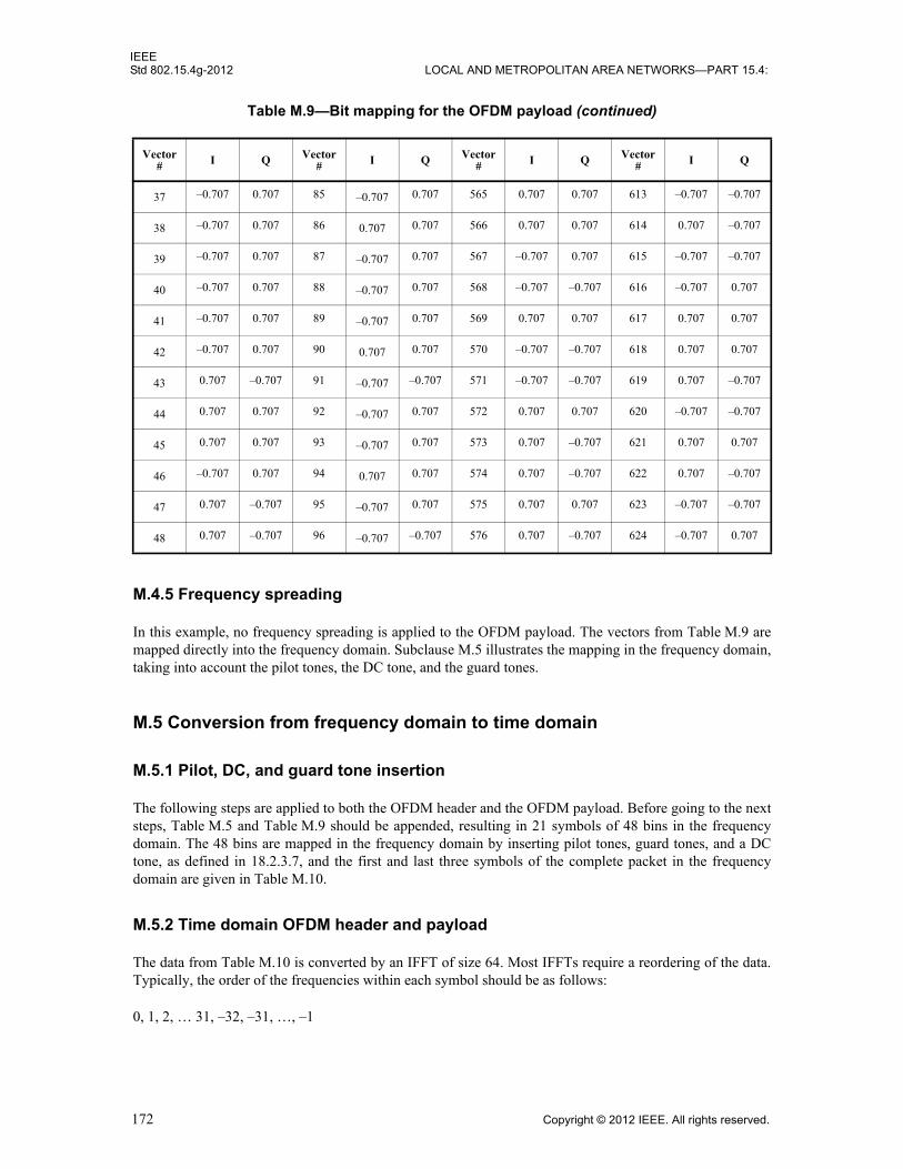
IEEEStd 802.15.4g-2012 LOCAL AND METROPOLITAN AREA NETWORKS—PART 15.4:
M.4.5 Frequency spreading
In this example, no frequency spreading is applied to the OFDM payload. The vectors from Table M.9 aremapped directly into the frequency domain. Subclause M.5 illustrates the mapping in the frequency domain,taking into account the pilot tones, the DC tone, and the guard tones.
M.5 Conversion from frequency domain to time domain
M.5.1 Pilot, DC, and guard tone insertion
The following steps are applied to both the OFDM header and the OFDM payload. Before going to the nextsteps, Table M.5 and Table M.9 should be appended, resulting in 21 symbols of 48 bins in the frequencydomain. The 48 bins are mapped in the frequency domain by inserting pilot tones, guard tones, and a DCtone, as defined in 18.2.3.7, and the first and last three symbols of the complete packet in the frequencydomain are given in Table M.10.
M.5.2 Time domain OFDM header and payload
The data from Table M.10 is converted by an IFFT of size 64. Most IFFTs require a reordering of the data.Typically, the order of the frequencies within each symbol should be as follows:
0, 1, 2, … 31, –32, –31, …, –1
37 –0.707 0.707 85 –0.707 0.707 565 0.707 0.707 613 –0.707 –0.707
38 –0.707 0.707 86 0.707 0.707 566 0.707 0.707 614 0.707 –0.707
39 –0.707 0.707 87 –0.707 0.707 567 –0.707 0.707 615 –0.707 –0.707
40 –0.707 0.707 88 –0.707 0.707 568 –0.707 –0.707 616 –0.707 0.707
41 –0.707 0.707 89 –0.707 0.707 569 0.707 0.707 617 0.707 0.707
42 –0.707 0.707 90 0.707 0.707 570 –0.707 –0.707 618 0.707 0.707
43 0.707 –0.707 91 –0.707 –0.707 571 –0.707 –0.707 619 0.707 –0.707
44 0.707 0.707 92 –0.707 0.707 572 0.707 0.707 620 –0.707 –0.707
45 0.707 0.707 93 –0.707 0.707 573 0.707 –0.707 621 0.707 0.707
46 –0.707 0.707 94 0.707 0.707 574 0.707 –0.707 622 0.707 –0.707
47 0.707 –0.707 95 –0.707 0.707 575 0.707 0.707 623 –0.707 –0.707
48 0.707 –0.707 96 –0.707 –0.707 576 0.707 –0.707 624 –0.707 0.707
Table M.9—Bit mapping for the OFDM payload (continued)
Vector# I Q Vector
# I Q Vector# I Q Vector
# I Q
172 Copyright © 2012 IEEE. All rights reserved.

IEEEWIRELESS MAC AND PHY SPECIFICATIONS FOR LR-WPANS—AMENDMENT 3 Std 802.15.4g-2012
Table M.10—Complete Packet in the frequency domain (first and last three symbols)
Subcarrier Symbol 1 Symbol 2 Symbol 3 Symbol 19 Symbol 20 Symbol 21
–32 0 0 0 0 0 0
–31 0 0 0 0 0 0
–30 0 0 0 0 0 0
–29 0 0 0 0 0 0
–28 0 0 0 0 0 0
–27 0 0 0 0 0 0
–26 –0 – 1i 0 + 1i 0 + 1i –0.707 + 0.707i –0.707 – 0.707i –1
–25 0 + 1i –0 – 1i –0 – 1i –0.707 – 0.707i –0.707 + 0.707i –0.707 + 0.707i
–24 0 + 1i –0 – 1i –0 – 1i 0.707 + 0.707i –0.707 + 0.707i –0.707 – 0.707i
–23 0 + 1i –0 – 1i –0 – 1i 0.707 – 0.707i –0.707 – 0.707i –0.707 + 0.707i
–22 –0 – 1i 1 –0 – 1i 1 –0.707 + 0.707i –0.707 – 0.707i
–21 –0 – 1i –0 – 1i –0 – 1i 0.707 – 0.707i –0.707 + 0.707i 0.707 – 0.707i
–20 0 – 1i 0 + 1i 0 – 1i 0.707 – 0.707i 0.707 + 0.707i –0.707 + 0.707i
–19 0 + 1i –0 + 1i –0 – 1i –0.707 – 0.707i –0.707 + 0.707i 0.707 + 0.707i
–18 –0 + 1i –0 – 1i –1 –0.707 – 0.707i –1 –0.707 – 0.707i
–17 0 + 1i 0 – 1i 0 – 1i 0.707 + 0.707i –0.707 – 0.707i –0.707 – 0.707i
–16 0 – 1i –0 – 1i 0 + 1i –0.707 – 0.707i –0.707 – 0.707i –0.707 + 0.707i
–15 –0 – 1i –0 + 1i –0 + 1i 0.707 + 0.707i 0.707 + 0.707i –0.707 – 0.707i
–14 –1 0 + 1i 0 + 1i 0.707 – 0.707i –0.707 + 0.707i –0.707 + 0.707i
–13 1 – 0i –1 + 0i –1 + 0i –0.707 – 0.707i 0.707 + 0.707i –0.707 – 0.707i
–12 –0 – 1i 0 + 1i 0 + 1i –0.707 + 0.707i –0.707 – 0.707i 0.707 – 0.707i
–11 1 – 0i –1 + 0i –1 + 0i –0.707 – 0.707i –0.707 + 0.707i –0.707 – 0.707i
–10 0 + 1i 1 –0 – 1i –1 –0.707 + 0.707i –0.707 + 0.707i
–9 1 – 0i –0 – 1i 1 – 0i 0.707 + 0.707i –0.707 + 0.707i 0.707 + 0.707i
–8 –0 + 1i 1 – 0i –0 + 1i –0.707 – 0.707i –0.707 – 0.707i –0.707 – 0.707i
–7 –1 + 0i 0 – 1i –1 + 0i 0.707 + 0.707i –0.707 + 0.707i 0.707 – 0.707i
–6 0 + 1i 1 – 0i 1 0.707 + 0.707i 1 –0.707 + 0.707i
–5 –1 – 0i –0 – 1i –0 – 1i 0.707 + 0.707i 0.707 + 0.707i –0.707 + 0.707i
–4 0 – 1i 1 + 0i 1 + 0i –0.707 + 0.707i 0.707 + 0.707i –0.707 + 0.707i
–3 –1 + 0i –0 + 1i 0 – 1i 0.707 – 0.707i 0.707 – 0.707i –0.707 – 0.707i
–2 –1 1 – 0i 1 – 0i 0.707 – 0.707i 0.707 – 0.707i –0.707 – 0.707i
–1 –0 – 1i 0 + 1i 0 + 1i 0.707 + 0.707i –0.707 + 0.707i –0.707 – 0.707i
Copyright © 2012 IEEE. All rights reserved. 173
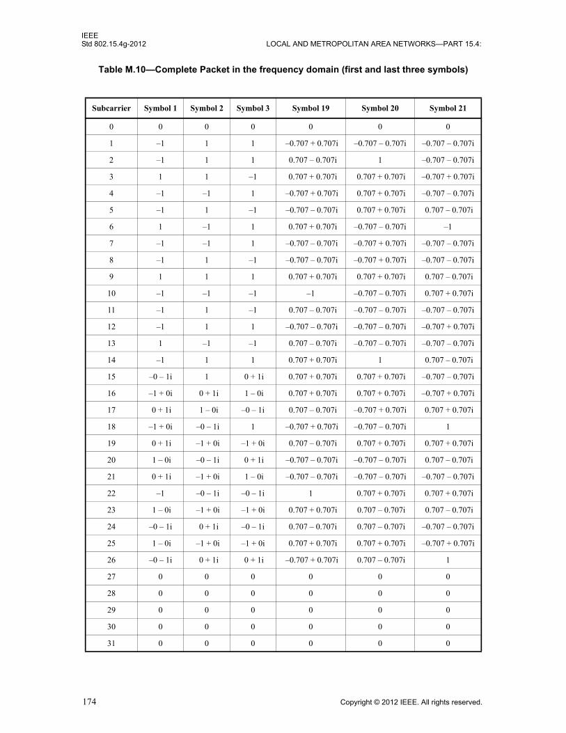
IEEEStd 802.15.4g-2012 LOCAL AND METROPOLITAN AREA NETWORKS—PART 15.4:
0 0 0 0 0 0 0
1 –1 1 1 –0.707 + 0.707i –0.707 – 0.707i –0.707 – 0.707i
2 –1 1 1 0.707 – 0.707i 1 –0.707 – 0.707i
3 1 1 –1 0.707 + 0.707i 0.707 + 0.707i –0.707 + 0.707i
4 –1 –1 1 –0.707 + 0.707i 0.707 + 0.707i –0.707 – 0.707i
5 –1 1 –1 –0.707 – 0.707i 0.707 + 0.707i 0.707 – 0.707i
6 1 –1 1 0.707 + 0.707i –0.707 – 0.707i –1
7 –1 –1 1 –0.707 – 0.707i –0.707 + 0.707i –0.707 – 0.707i
8 –1 1 –1 –0.707 – 0.707i –0.707 + 0.707i –0.707 – 0.707i
9 1 1 1 0.707 + 0.707i 0.707 + 0.707i 0.707 – 0.707i
10 –1 –1 –1 –1 –0.707 – 0.707i 0.707 + 0.707i
11 –1 1 –1 0.707 – 0.707i –0.707 – 0.707i –0.707 – 0.707i
12 –1 1 1 –0.707 – 0.707i –0.707 – 0.707i –0.707 + 0.707i
13 1 –1 –1 0.707 – 0.707i –0.707 – 0.707i –0.707 – 0.707i
14 –1 1 1 0.707 + 0.707i 1 0.707 – 0.707i
15 –0 – 1i 1 0 + 1i 0.707 + 0.707i 0.707 + 0.707i –0.707 – 0.707i
16 –1 + 0i 0 + 1i 1 – 0i 0.707 + 0.707i 0.707 + 0.707i –0.707 + 0.707i
17 0 + 1i 1 – 0i –0 – 1i 0.707 – 0.707i –0.707 + 0.707i 0.707 + 0.707i
18 –1 + 0i –0 – 1i 1 –0.707 + 0.707i –0.707 – 0.707i 1
19 0 + 1i –1 + 0i –1 + 0i 0.707 – 0.707i 0.707 + 0.707i 0.707 + 0.707i
20 1 – 0i –0 – 1i 0 + 1i –0.707 – 0.707i –0.707 – 0.707i 0.707 – 0.707i
21 0 + 1i –1 + 0i 1 – 0i –0.707 – 0.707i –0.707 – 0.707i –0.707 – 0.707i
22 –1 –0 – 1i –0 – 1i 1 0.707 + 0.707i 0.707 + 0.707i
23 1 – 0i –1 + 0i –1 + 0i 0.707 + 0.707i 0.707 – 0.707i 0.707 – 0.707i
24 –0 – 1i 0 + 1i –0 – 1i 0.707 – 0.707i 0.707 – 0.707i –0.707 – 0.707i
25 1 – 0i –1 + 0i –1 + 0i 0.707 + 0.707i 0.707 + 0.707i –0.707 + 0.707i
26 –0 – 1i 0 + 1i 0 + 1i –0.707 + 0.707i 0.707 – 0.707i 1
27 0 0 0 0 0 0
28 0 0 0 0 0 0
29 0 0 0 0 0 0
30 0 0 0 0 0 0
31 0 0 0 0 0 0
Table M.10—Complete Packet in the frequency domain (first and last three symbols)
Subcarrier Symbol 1 Symbol 2 Symbol 3 Symbol 19 Symbol 20 Symbol 21
174 Copyright © 2012 IEEE. All rights reserved.

IEEEWIRELESS MAC AND PHY SPECIFICATIONS FOR LR-WPANS—AMENDMENT 3 Std 802.15.4g-2012
After the IFFT, each symbol is extended by a CP of 16 samples. Each OFDM symbol then has a size of 80samples (64 +16).
The resulting data in the time domain has 1680 samples ( ).
M.6 The entire packet
The complete packet in the time domain is represented in Table M.11. The STF is from sample 1 to 320. TheLTF is from sample 321 to 480. The OFDM header and payload are from sample 481 to 2160.
Table M.11—Complete packet
Sample I Q Sample I Q Sample I Q
1 0.6505 0.0000 721 1.2500 0.2500 1441 0.2500 –0.3536
2 1.0989 0.6505 722 0.8614 –0.4695 1442 0.1638 0.5643
3 0.4600 –1.3010 723 –0.2908 –0.2253 1443 0.7775 0.6229
4 –0.9531 –0.6505 724 0.5001 0.3738 1444 0.9942 0.7243
5 0.0000 0.0000 725 1.1311 –0.9157 1445 0.6081 1.1384
6 0.9531 0.6505 726 –0.4053 –0.2634 1446 0.3631 0.0038
7 –0.4600 1.3010 727 –0.6643 0.4820 1447 –0.4662 0.1814
8 –1.0989 –0.6505 728 1.0328 –0.5564 1448 0.2806 0.4162
9 –0.6505 0.0000 729 0.3750 –0.3750 1449 0.9053 0.0947
10 –1.0989 0.6505 730 –0.0528 –0.5851 1450 0.2529 0.6731
11 –0.4600 –1.3010 731 –0.1631 –0.2493 1451 0.1342 0.4139
12 0.9531 –0.6505 732 –0.8028 1.0475 1452 –1.1735 0.4862
13 0.0000 0.0000 733 0.3377 1.0436 1453 –0.6809 0.1824
14 –0.9531 0.6505 734 0.1681 0.9115 1454 0.8025 –0.7485
15 0.4600 1.3010 735 0.4341 0.3737 1455 0.0997 –0.3608
16 1.0989 –0.6505 736 0.6505 –0.1614 1456 0.3491 –0.7509
17 0.6505 0.0000 737 –0.5000 –0.5000 1457 –0.0732 –0.5303
18 1.0989 0.6505 738 0.5418 –0.1548 1458 –1.3972 0.5182
19 0.4600 –1.3010 739 –0.0330 1.1371 1459 –0.2265 –0.3269
20 –0.9531 –0.6505 740 –0.9736 –0.5277 1460 0.6019 –0.3736
21 80×
Copyright © 2012 IEEE. All rights reserved. 175

IEEEStd 802.15.4g-2012 LOCAL AND METROPOLITAN AREA NETWORKS—PART 15.4:
21 0.0000 0.0000 741 0.2177 –1.2005 1461 –0.9452 0.2922
22 0.9531 0.6505 742 0.2514 1.0265 1462 –0.5092 –0.0185
23 –0.4600 1.3010 743 0.0867 0.3962 1463 0.7862 –0.2370
24 –1.0989 –0.6505 744 0.3458 –0.0062 1464 –0.3930 –0.6599
25 –0.6505 0.0000 745 0.5518 0.3018 1465 –0.2589 –0.3018
26 –1.0989 0.6505 746 –0.1912 0.0665 1466 –0.2738 0.5548
27 –0.4600 –1.3010 747 0.0960 1.0100 1467 –0.3484 –0.1781
28 0.9531 –0.6505 748 0.8195 –0.5387 1468 0.9250 –0.9967
29 0.0000 0.0000 749 –0.8187 –1.0658 1469 –0.6667 –0.0867
30 –0.9531 0.6505 750 –0.2341 0.9365 1470 –0.9835 0.5927
31 0.4600 1.3010 751 0.4301 0.0436 1471 –0.2062 –0.1478
32 1.0989 –0.6505 752 –0.4539 –0.3529 1472 –0.0100 –0.1180
33 0.6505 0.0000 753 0.5000 0.5000 1473 1.3107 0.0000
34 1.0989 0.6505 754 0.0498 0.2651 1474 –0.4684 –0.4770
35 0.4600 –1.3010 755 –0.8625 0.1513 1475 –0.6153 0.7666
36 –0.9531 –0.6505 756 –1.0981 –0.0971 1476 0.4219 1.2002
37 0.0000 0.0000 757 –1.2346 –0.1272 1477 –0.7545 –0.2242
38 0.9531 0.6505 758 –0.1915 –0.8806 1478 0.7262 0.0117
39 –0.4600 1.3010 759 0.3108 –1.2437 1479 0.9370 0.1976
40 –1.0989 –0.6505 760 0.5270 –0.2394 1480 0.2246 –1.4293
41 –0.6505 0.0000 761 0.3750 –0.3750 1481 0.1553 –1.6553
42 –1.0989 0.6505 762 –0.4575 –0.2182 1482 –0.5419 –0.0881
43 –0.4600 –1.3010 763 –0.6075 –0.6365 1483 0.4107 –0.0603
44 0.9531 –0.6505 764 0.5883 –1.4165 1484 –0.3997 –0.6063
45 0.0000 0.0000 765 0.4730 0.4135 1485 –1.0868 0.3176
46 –0.9531 0.6505 766 –1.4108 0.5658 1486 –0.3842 0.3305
47 0.4600 1.3010 767 –0.0805 –0.6480 1487 –0.5168 0.1986
Table M.11—Complete packet (continued)
Sample I Q Sample I Q Sample I Q
176 Copyright © 2012 IEEE. All rights reserved.
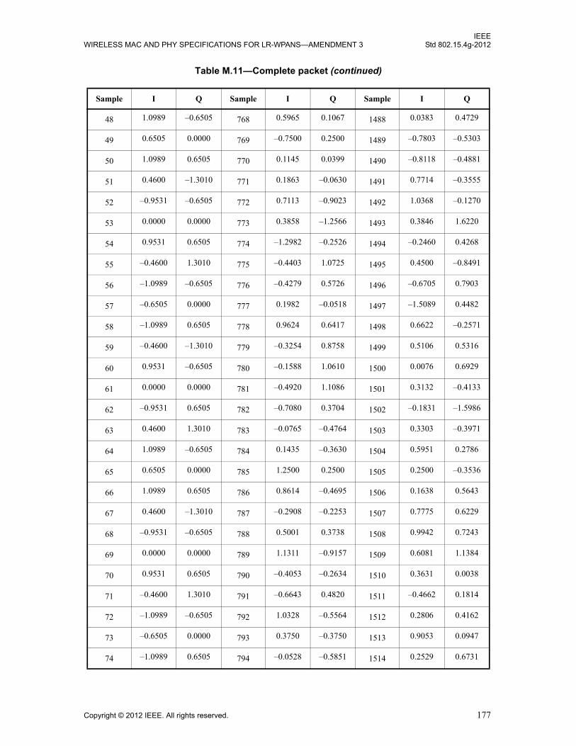
IEEEWIRELESS MAC AND PHY SPECIFICATIONS FOR LR-WPANS—AMENDMENT 3 Std 802.15.4g-2012
48 1.0989 –0.6505 768 0.5965 0.1067 1488 0.0383 0.4729
49 0.6505 0.0000 769 –0.7500 0.2500 1489 –0.7803 –0.5303
50 1.0989 0.6505 770 0.1145 0.0399 1490 –0.8118 –0.4881
51 0.4600 –1.3010 771 0.1863 –0.0630 1491 0.7714 –0.3555
52 –0.9531 –0.6505 772 0.7113 –0.9023 1492 1.0368 –0.1270
53 0.0000 0.0000 773 0.3858 –1.2566 1493 0.3846 1.6220
54 0.9531 0.6505 774 –1.2982 –0.2526 1494 –0.2460 0.4268
55 –0.4600 1.3010 775 –0.4403 1.0725 1495 0.4500 –0.8491
56 –1.0989 –0.6505 776 –0.4279 0.5726 1496 –0.6705 0.7903
57 –0.6505 0.0000 777 0.1982 –0.0518 1497 –1.5089 0.4482
58 –1.0989 0.6505 778 0.9624 0.6417 1498 0.6622 –0.2571
59 –0.4600 –1.3010 779 –0.3254 0.8758 1499 0.5106 0.5316
60 0.9531 –0.6505 780 –0.1588 1.0610 1500 0.0076 0.6929
61 0.0000 0.0000 781 –0.4920 1.1086 1501 0.3132 –0.4133
62 –0.9531 0.6505 782 –0.7080 0.3704 1502 –0.1831 –1.5986
63 0.4600 1.3010 783 –0.0765 –0.4764 1503 0.3303 –0.3971
64 1.0989 –0.6505 784 0.1435 –0.3630 1504 0.5951 0.2786
65 0.6505 0.0000 785 1.2500 0.2500 1505 0.2500 –0.3536
66 1.0989 0.6505 786 0.8614 –0.4695 1506 0.1638 0.5643
67 0.4600 –1.3010 787 –0.2908 –0.2253 1507 0.7775 0.6229
68 –0.9531 –0.6505 788 0.5001 0.3738 1508 0.9942 0.7243
69 0.0000 0.0000 789 1.1311 –0.9157 1509 0.6081 1.1384
70 0.9531 0.6505 790 –0.4053 –0.2634 1510 0.3631 0.0038
71 –0.4600 1.3010 791 –0.6643 0.4820 1511 –0.4662 0.1814
72 –1.0989 –0.6505 792 1.0328 –0.5564 1512 0.2806 0.4162
73 –0.6505 0.0000 793 0.3750 –0.3750 1513 0.9053 0.0947
74 –1.0989 0.6505 794 –0.0528 –0.5851 1514 0.2529 0.6731
Table M.11—Complete packet (continued)
Sample I Q Sample I Q Sample I Q
Copyright © 2012 IEEE. All rights reserved. 177

IEEEStd 802.15.4g-2012 LOCAL AND METROPOLITAN AREA NETWORKS—PART 15.4:
75 –0.4600 –1.3010 795 –0.1631 –0.2493 1515 0.1342 0.4139
76 0.9531 –0.6505 796 –0.8028 1.0475 1516 –1.1735 0.4862
77 0.0000 0.0000 797 0.3377 1.0436 1517 –0.6809 0.1824
78 –0.9531 0.6505 798 0.1681 0.9115 1518 0.8025 –0.7485
79 0.4600 1.3010 799 0.4341 0.3737 1519 0.0997 –0.3608
80 1.0989 –0.6505 800 0.6505 –0.1614 1520 0.3491 –0.7509
81 0.6505 0.0000 801 –0.5000 –0.2500 1521 –0.2803 –0.3536
82 1.0989 0.6505 802 –0.0317 0.8648 1522 –0.6641 0.9523
83 0.4600 –1.3010 803 –0.9607 0.0501 1523 –1.1246 –0.2387
84 –0.9531 –0.6505 804 0.7640 –0.2991 1524 0.2415 –0.5844
85 0.0000 0.0000 805 1.1961 0.6546 1525 0.5901 –0.5569
86 0.9531 0.6505 806 0.2388 0.2248 1526 –0.4015 –0.2023
87 –0.4600 1.3010 807 0.0467 0.4232 1527 0.5738 –0.7872
88 –1.0989 –0.6505 808 –0.0033 –0.2475 1528 0.7747 –0.7146
89 –0.6505 0.0000 809 0.3750 –0.8750 1529 –0.3018 0.7714
90 –1.0989 0.6505 810 –0.6716 1.0428 1530 –0.3357 –0.4211
91 –0.4600 –1.3010 811 –0.6920 1.1976 1531 –0.2209 –0.3889
92 0.9531 –0.6505 812 –0.3902 –0.1775 1532 –0.1251 0.0314
93 0.0000 0.0000 813 –0.6083 0.2576 1533 0.3591 –0.8211
94 –0.9531 0.6505 814 0.7307 0.7500 1534 0.1504 0.0247
95 0.4600 1.3010 815 0.0267 0.1909 1535 –0.3983 –0.2610
96 1.0989 –0.6505 816 –1.3111 0.2567 1536 –0.0178 –0.2952
97 0.6505 0.0000 817 –0.7500 0.5000 1537 –0.2500 0.5303
98 1.0989 0.6505 818 –0.4114 –0.5356 1538 –0.8138 0.0300
99 0.4600 –1.3010 819 –0.4178 –0.6116 1539 0.0210 –0.6510
100 –0.9531 –0.6505 820 0.0996 0.3420 1540 –0.0351 –0.6107
101 0.0000 0.0000 821 0.4202 –0.2297 1541 –0.1409 0.2153
Table M.11—Complete packet (continued)
Sample I Q Sample I Q Sample I Q
178 Copyright © 2012 IEEE. All rights reserved.

IEEEWIRELESS MAC AND PHY SPECIFICATIONS FOR LR-WPANS—AMENDMENT 3 Std 802.15.4g-2012
102 0.9531 0.6505 822 –0.8027 –0.7097 1542 1.2834 0.4578
103 –0.4600 1.3010 823 –1.0913 –0.4436 1543 1.0654 1.0381
104 –1.0989 –0.6505 824 –0.1646 –0.3029 1544 –0.2934 0.6271
105 –0.6505 0.0000 825 0.0518 0.4482 1545 –0.6553 –0.2286
106 –1.0989 0.6505 826 0.1405 0.6933 1546 –0.4317 1.7310
107 –0.4600 –1.3010 827 0.1632 –0.2845 1547 0.2617 1.7355
108 0.9531 –0.6505 828 0.8089 –0.6057 1548 0.6881 0.2490
109 0.0000 0.0000 829 0.1654 0.3787 1549 0.0901 0.1012
110 –0.9531 0.6505 830 –0.4424 0.8356 1550 –0.3210 –0.5197
111 0.4600 1.3010 831 1.4504 0.7296 1551 0.6630 –0.6271
112 1.0989 –0.6505 832 1.1508 0.7681 1552 0.1507 –0.7894
113 0.6505 0.0000 833 –0.2500 –0.5000 1553 –1.6945 –0.3536
114 1.0989 0.6505 834 0.5813 –1.2438 1554 –0.3474 –0.1794
115 0.4600 –1.3010 835 0.9020 –0.0004 1555 0.8746 –0.8199
116 –0.9531 –0.6505 836 –0.1068 0.2798 1556 0.1357 0.9088
117 0.0000 0.0000 837 0.4075 –0.4046 1557 0.2635 1.6175
118 0.9531 0.6505 838 0.9756 –0.4730 1558 –0.3064 0.1162
119 –0.4600 1.3010 839 –1.0831 –0.3735 1559 0.4625 0.1133
120 –1.0989 –0.6505 840 –0.8955 –0.8044 1560 1.6210 –0.0821
121 –0.6505 0.0000 841 0.3750 –0.8750 1561 –0.0518 –0.9786
122 –1.0989 0.6505 842 0.2269 –0.2881 1562 0.1806 0.3627
123 –0.4600 –1.3010 843 0.9039 –0.8235 1563 1.1242 0.9063
124 0.9531 –0.6505 844 –0.4775 –0.0295 1564 0.3398 –0.6203
125 0.0000 0.0000 845 –0.2024 1.6995 1565 0.4944 –0.0325
126 –0.9531 0.6505 846 1.1315 0.2718 1566 0.2677 –0.2664
127 0.4600 1.3010 847 –0.6849 –0.3580 1567 0.0108 –0.2596
128 1.0989 –0.6505 848 –0.3707 0.1709 1568 –0.1347 1.6860
Table M.11—Complete packet (continued)
Sample I Q Sample I Q Sample I Q
Copyright © 2012 IEEE. All rights reserved. 179
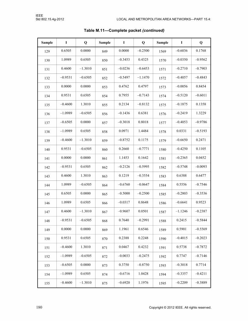
IEEEStd 802.15.4g-2012 LOCAL AND METROPOLITAN AREA NETWORKS—PART 15.4:
129 0.6505 0.0000 849 0.0000 –0.2500 1569 –0.6036 0.1768
130 1.0989 0.6505 850 –0.3453 0.4325 1570 –0.0350 –0.9562
131 0.4600 –1.3010 851 –0.0236 –0.6453 1571 –0.2710 –0.7903
132 –0.9531 –0.6505 852 –0.5497 –1.1470 1572 –0.4057 –0.4843
133 0.0000 0.0000 853 0.4762 0.4797 1573 –0.0056 0.8454
134 0.9531 0.6505 854 0.7955 –0.7143 1574 –0.5120 –0.6011
135 –0.4600 1.3010 855 0.2134 –0.8132 1575 –0.1875 0.1358
136 –1.0989 –0.6505 856 –0.1436 0.6381 1576 –0.2419 1.3229
137 –0.6505 0.0000 857 –0.3018 0.8018 1577 –0.4053 –0.9786
138 –1.0989 0.6505 858 0.0971 1.4484 1578 0.0331 –0.5193
139 –0.4600 –1.3010 859 –0.8752 0.1175 1579 –0.6650 0.2471
140 0.9531 –0.6505 860 0.2660 –0.7771 1580 –0.4250 0.1105
141 0.0000 0.0000 861 1.1453 0.1642 1581 –0.2365 0.0452
142 –0.9531 0.6505 862 –0.2126 –0.5995 1582 –0.5748 –0.0093
143 0.4600 1.3010 863 0.1219 –0.3554 1583 0.6388 0.6477
144 1.0989 –0.6505 864 –0.6760 –0.0647 1584 0.5556 –0.7546
145 0.6505 0.0000 865 –0.5000 –0.2500 1585 –0.2803 –0.3536
146 1.0989 0.6505 866 –0.0317 0.8648 1586 –0.6641 0.9523
147 0.4600 –1.3010 867 –0.9607 0.0501 1587 –1.1246 –0.2387
148 –0.9531 –0.6505 868 0.7640 –0.2991 1588 0.2415 –0.5844
149 0.0000 0.0000 869 1.1961 0.6546 1589 0.5901 –0.5569
150 0.9531 0.6505 870 0.2388 0.2248 1590 –0.4015 –0.2023
151 –0.4600 1.3010 871 0.0467 0.4232 1591 0.5738 –0.7872
152 –1.0989 –0.6505 872 –0.0033 –0.2475 1592 0.7747 –0.7146
153 –0.6505 0.0000 873 0.3750 –0.8750 1593 –0.3018 0.7714
154 –1.0989 0.6505 874 –0.6716 1.0428 1594 –0.3357 –0.4211
155 –0.4600 –1.3010 875 –0.6920 1.1976 1595 –0.2209 –0.3889
Table M.11—Complete packet (continued)
Sample I Q Sample I Q Sample I Q
180 Copyright © 2012 IEEE. All rights reserved.

IEEEWIRELESS MAC AND PHY SPECIFICATIONS FOR LR-WPANS—AMENDMENT 3 Std 802.15.4g-2012
156 0.9531 –0.6505 876 –0.3902 –0.1775 1596 –0.1251 0.0314
157 0.0000 0.0000 877 –0.6083 0.2576 1597 0.3591 –0.8211
158 –0.9531 0.6505 878 0.7307 0.7500 1598 0.1504 0.0247
159 0.4600 1.3010 879 0.0267 0.1909 1599 –0.3983 –0.2610
160 1.0989 –0.6505 880 –1.3111 0.2567 1600 –0.0178 –0.2952
161 0.6505 0.0000 881 –0.2500 0.2500 1601 –0.5303 0.3536
162 1.0989 0.6505 882 –0.4951 –0.6501 1602 0.0362 0.1951
163 0.4600 –1.3010 883 0.7030 0.1442 1603 1.5894 –0.2734
164 –0.9531 –0.6505 884 –0.6414 –0.3636 1604 1.1743 –0.7905
165 0.0000 0.0000 885 –0.4358 –1.3977 1605 0.0957 –0.2037
166 0.9531 0.6505 886 1.0506 0.2340 1606 0.7194 1.0870
167 –0.4600 1.3010 887 0.0779 –0.1987 1607 –0.4588 0.9484
168 –1.0989 –0.6505 888 –0.6380 –0.1150 1608 –0.7891 –0.1564
169 –0.6505 0.0000 889 –0.2286 0.4786 1609 –0.4268 –0.2197
170 –1.0989 0.6505 890 0.4263 –0.0201 1610 –1.0270 –0.3090
171 –0.4600 –1.3010 891 0.7092 0.9469 1611 0.0165 0.0962
172 0.9531 –0.6505 892 0.6284 0.5555 1612 0.1871 0.3372
173 0.0000 0.0000 893 0.5090 –0.1824 1613 0.3932 –0.8887
174 –0.9531 0.6505 894 –0.5295 0.0510 1614 0.9380 –0.8866
175 0.4600 1.3010 895 –1.0252 –0.5532 1615 0.2672 –0.2544
176 1.0989 –0.6505 896 –0.0839 –1.1538 1616 –0.2780 0.2540
177 0.6505 0.0000 897 0.2500 –0.2500 1617 –0.5303 0.3536
178 1.0989 0.6505 898 –0.5004 1.3005 1618 0.2614 –0.5484
179 0.4600 –1.3010 899 –0.5908 0.6231 1619 –0.8440 0.4400
180 –0.9531 –0.6505 900 0.0577 –0.2707 1620 –1.9533 0.4834
181 0.0000 0.0000 901 –0.1218 –0.4305 1621 –0.2310 –0.6656
182 0.9531 0.6505 902 0.3491 –1.1041 1622 –0.6724 0.7313
Table M.11—Complete packet (continued)
Sample I Q Sample I Q Sample I Q
Copyright © 2012 IEEE. All rights reserved. 181

IEEEStd 802.15.4g-2012 LOCAL AND METROPOLITAN AREA NETWORKS—PART 15.4:
183 –0.4600 1.3010 903 0.9989 –0.6519 1623 –1.0910 0.6826
184 –1.0989 –0.6505 904 –0.4581 0.2200 1624 0.3620 0.3533
185 –0.6505 0.0000 905 –0.3018 0.4053 1625 0.0732 0.6768
186 –1.0989 0.6505 906 1.3908 –0.6853 1626 –1.2539 –0.9391
187 –0.4600 –1.3010 907 0.3587 –1.0781 1627 –0.4299 –0.3482
188 0.9531 –0.6505 908 –0.6375 0.0748 1628 1.1011 0.7877
189 0.0000 0.0000 909 –0.0486 –0.0867 1629 –0.2041 0.2646
190 –0.9531 0.6505 910 –0.6249 –0.0633 1630 –0.3363 0.0068
191 0.4600 1.3010 911 –1.0181 0.3954 1631 0.6177 –0.6401
192 1.0989 –0.6505 912 –0.2391 0.0433 1632 0.3011 0.0302
193 0.6505 0.0000 913 –1.0000 –0.5000 1633 0.1768 0.0000
194 1.0989 0.6505 914 –1.7777 –0.6477 1634 –1.5594 –0.5893
195 0.4600 –1.3010 915 –0.4418 0.0534 1635 –0.4155 0.6856
196 –0.9531 –0.6505 916 0.0513 0.0869 1636 1.9024 –0.2646
197 0.0000 0.0000 917 0.0822 0.0442 1637 –0.0957 –0.8570
198 0.9531 0.6505 918 0.2833 0.1666 1638 –0.2773 –0.1770
199 –0.4600 1.3010 919 –0.6388 0.5428 1639 0.3621 –1.1312
200 –1.0989 –0.6505 920 –0.0179 0.7491 1640 –0.4501 –0.2002
201 –0.6505 0.0000 921 0.4786 –0.2286 1641 0.0732 0.2803
202 –1.0989 0.6505 922 –0.4198 0.6797 1642 0.3684 –0.1857
203 –0.4600 –1.3010 923 0.7210 –0.0705 1643 –0.2665 0.8520
204 0.9531 –0.6505 924 1.2626 –2.0318 1644 –0.3789 0.4118
205 0.0000 0.0000 925 –0.0090 –0.3176 1645 0.3139 0.0352
206 –0.9531 0.6505 926 –0.4956 0.0872 1646 –0.2635 –0.1559
207 0.4600 1.3010 927 0.1654 0.3233 1647 –0.1704 –0.1578
208 1.0989 –0.6505 928 1.0042 0.6618 1648 0.9103 1.4900
209 0.6505 0.0000 929 0.0000 –0.5000 1649 0.1768 0.7071
Table M.11—Complete packet (continued)
Sample I Q Sample I Q Sample I Q
182 Copyright © 2012 IEEE. All rights reserved.

IEEEWIRELESS MAC AND PHY SPECIFICATIONS FOR LR-WPANS—AMENDMENT 3 Std 802.15.4g-2012
210 1.0989 0.6505 930 –0.0522 0.2679 1650 0.1668 –0.3766
211 0.4600 –1.3010 931 1.1226 0.3863 1651 0.1701 0.3549
212 –0.9531 –0.6505 932 0.2618 0.1109 1652 0.3542 –0.2571
213 0.0000 0.0000 933 0.4754 –0.2159 1653 0.2310 –0.3950
214 0.9531 0.6505 934 0.4427 0.0502 1654 –1.5540 –0.2712
215 –0.4600 1.3010 935 –0.5238 1.8078 1655 –0.3123 –0.7069
216 –1.0989 –0.6505 936 0.4607 0.5063 1656 0.4310 0.0159
217 –0.6505 0.0000 937 0.0518 –0.6553 1657 –0.4268 0.6768
218 –1.0989 0.6505 938 0.0141 –0.2449 1658 0.5933 0.3388
219 –0.4600 –1.3010 939 0.4182 –0.0054 1659 0.1799 –0.3929
220 0.9531 –0.6505 940 –0.9829 0.4238 1660 0.0273 –0.2936
221 0.0000 0.0000 941 0.5486 –0.4133 1661 0.9112 –0.1181
222 –0.9531 0.6505 942 0.9385 0.5784 1662 1.0318 –0.7486
223 0.4600 1.3010 943 –1.0362 1.3345 1663 0.7856 –0.1548
224 1.0989 –0.6505 944 –0.0279 0.5026 1664 –0.0730 0.6274
225 0.6505 0.0000 945 –0.2500 0.2500 1665 –0.5303 0.3536
226 1.0989 0.6505 946 –0.4951 –0.6501 1666 0.0362 0.1951
227 0.4600 –1.3010 947 0.7030 0.1442 1667 1.5894 –0.2734
228 –0.9531 –0.6505 948 –0.6414 –0.3636 1668 1.1743 –0.7905
229 0.0000 0.0000 949 –0.4358 –1.3977 1669 0.0957 –0.2037
230 0.9531 0.6505 950 1.0506 0.2340 1670 0.7194 1.0870
231 –0.4600 1.3010 951 0.0779 –0.1987 1671 –0.4588 0.9484
232 –1.0989 –0.6505 952 –0.6380 –0.1150 1672 –0.7891 –0.1564
233 –0.6505 0.0000 953 –0.2286 0.4786 1673 –0.4268 –0.2197
234 –1.0989 0.6505 954 0.4263 –0.0201 1674 –1.0270 –0.3090
235 –0.4600 –1.3010 955 0.7092 0.9469 1675 0.0165 0.0962
236 0.9531 –0.6505 956 0.6284 0.5555 1676 0.1871 0.3372
Table M.11—Complete packet (continued)
Sample I Q Sample I Q Sample I Q
Copyright © 2012 IEEE. All rights reserved. 183

IEEEStd 802.15.4g-2012 LOCAL AND METROPOLITAN AREA NETWORKS—PART 15.4:
237 0.0000 0.0000 957 0.5090 –0.1824 1677 0.3932 –0.8887
238 –0.9531 0.6505 958 –0.5295 0.0510 1678 0.9380 –0.8866
239 0.4600 1.3010 959 –1.0252 –0.5532 1679 0.2672 –0.2544
240 1.0989 –0.6505 960 –0.0839 –1.1538 1680 –0.2780 0.2540
241 0.6505 0.0000 961 0.2500 0.0000 1681 0.1036 0.3536
242 1.0989 0.6505 962 –1.1885 –0.0517 1682 0.0422 0.3606
243 0.4600 –1.3010 963 0.1997 –1.4317 1683 –1.2262 0.7068
244 –0.9531 –0.6505 964 0.9695 –0.3270 1684 0.1929 –0.2507
245 0.0000 0.0000 965 –0.9360 0.8515 1685 0.8657 –1.2428
246 0.9531 0.6505 966 –0.2959 0.2999 1686 0.7129 –0.2952
247 –0.4600 1.3010 967 –0.1250 –0.3056 1687 1.0229 0.8315
248 –1.0989 –0.6505 968 0.4167 –0.1605 1688 0.4230 0.3020
249 –0.6505 0.0000 969 0.4268 0.7500 1689 0.3232 –0.8536
250 –1.0989 0.6505 970 –0.1728 0.7154 1690 –0.7755 –0.8068
251 –0.4600 –1.3010 971 0.3569 0.0708 1691 –0.3816 –0.4457
252 0.9531 –0.6505 972 –0.7639 0.0450 1692 0.0679 –0.9573
253 0.0000 0.0000 973 –0.2207 –0.2286 1693 –1.1094 –0.9405
254 –0.9531 0.6505 974 0.5312 0.1754 1694 –0.4555 –0.9108
255 0.4600 1.3010 975 –1.0181 0.6869 1695 –0.3856 –1.1829
256 1.0989 –0.6505 976 –1.4411 0.1403 1696 0.7023 0.1252
257 0.6505 0.0000 977 –1.2500 0.2500 1697 1.3107 0.3536
258 1.0989 0.6505 978 –0.9559 –0.0985 1698 0.0255 –1.3087
259 0.4600 –1.3010 979 –0.8175 –0.9460 1699 0.7765 –0.4359
260 –0.9531 –0.6505 980 –0.2337 0.1601 1700 –0.0586 0.7280
261 0.0000 0.0000 981 0.1268 0.8224 1701 –0.7558 –0.4427
262 0.9531 0.6505 982 –0.2803 –0.2552 1702 0.1002 0.0806
263 –0.4600 1.3010 983 0.0969 –0.5384 1703 –0.2591 1.4714
Table M.11—Complete packet (continued)
Sample I Q Sample I Q Sample I Q
184 Copyright © 2012 IEEE. All rights reserved.
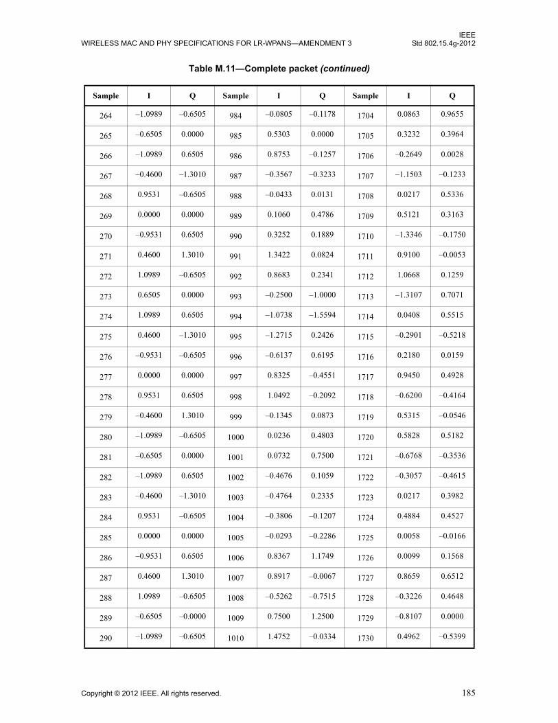
IEEEWIRELESS MAC AND PHY SPECIFICATIONS FOR LR-WPANS—AMENDMENT 3 Std 802.15.4g-2012
264 –1.0989 –0.6505 984 –0.0805 –0.1178 1704 0.0863 0.9655
265 –0.6505 0.0000 985 0.5303 0.0000 1705 0.3232 0.3964
266 –1.0989 0.6505 986 0.8753 –0.1257 1706 –0.2649 0.0028
267 –0.4600 –1.3010 987 –0.3567 –0.3233 1707 –1.1503 –0.1233
268 0.9531 –0.6505 988 –0.0433 0.0131 1708 0.0217 0.5336
269 0.0000 0.0000 989 0.1060 0.4786 1709 0.5121 0.3163
270 –0.9531 0.6505 990 0.3252 0.1889 1710 –1.3346 –0.1750
271 0.4600 1.3010 991 1.3422 0.0824 1711 0.9100 –0.0053
272 1.0989 –0.6505 992 0.8683 0.2341 1712 1.0668 0.1259
273 0.6505 0.0000 993 –0.2500 –1.0000 1713 –1.3107 0.7071
274 1.0989 0.6505 994 –1.0738 –1.5594 1714 0.0408 0.5515
275 0.4600 –1.3010 995 –1.2715 0.2426 1715 –0.2901 –0.5218
276 –0.9531 –0.6505 996 –0.6137 0.6195 1716 0.2180 0.0159
277 0.0000 0.0000 997 0.8325 –0.4551 1717 0.9450 0.4928
278 0.9531 0.6505 998 1.0492 –0.2092 1718 –0.6200 –0.4164
279 –0.4600 1.3010 999 –0.1345 0.0873 1719 0.5315 –0.0546
280 –1.0989 –0.6505 1000 0.0236 0.4803 1720 0.5828 0.5182
281 –0.6505 0.0000 1001 0.0732 0.7500 1721 –0.6768 –0.3536
282 –1.0989 0.6505 1002 –0.4676 0.1059 1722 –0.3057 –0.4615
283 –0.4600 –1.3010 1003 –0.4764 0.2335 1723 0.0217 0.3982
284 0.9531 –0.6505 1004 –0.3806 –0.1207 1724 0.4884 0.4527
285 0.0000 0.0000 1005 –0.0293 –0.2286 1725 0.0058 –0.0166
286 –0.9531 0.6505 1006 0.8367 1.1749 1726 0.0099 0.1568
287 0.4600 1.3010 1007 0.8917 –0.0067 1727 0.8659 0.6512
288 1.0989 –0.6505 1008 –0.5262 –0.7515 1728 –0.3226 0.4648
289 –0.6505 –0.0000 1009 0.7500 1.2500 1729 –0.8107 0.0000
290 –1.0989 –0.6505 1010 1.4752 –0.0334 1730 0.4962 –0.5399
Table M.11—Complete packet (continued)
Sample I Q Sample I Q Sample I Q
Copyright © 2012 IEEE. All rights reserved. 185

IEEEStd 802.15.4g-2012 LOCAL AND METROPOLITAN AREA NETWORKS—PART 15.4:
291 –0.4600 1.3010 1011 –0.5249 –1.2791 1731 –0.1744 –0.9562
292 0.9531 0.6505 1012 0.8557 0.5252 1732 –0.7985 0.3671
293 0.0000 –0.0000 1013 0.4767 0.2812 1733 0.3594 1.8998
294 –0.9531 –0.6505 1014 –0.9603 –0.3229 1734 0.5597 1.0772
295 0.4600 –1.3010 1015 0.4555 0.0495 1735 0.6190 –0.0412
296 1.0989 0.6505 1016 –0.4136 –0.2559 1736 –0.1555 –0.3080
297 0.6505 0.0000 1017 –0.5303 –0.0000 1737 –0.6768 –0.6036
298 1.0989 –0.6505 1018 0.0939 –0.3668 1738 0.3272 –0.2122
299 0.4600 1.3010 1019 0.8905 –0.5668 1739 –0.4040 –0.0363
300 –0.9531 0.6505 1020 1.6244 0.4992 1740 0.2824 –0.4751
301 0.0000 –0.0000 1021 –0.3560 0.4786 1741 0.5914 –0.0663
302 0.9531 –0.6505 1022 0.2086 0.3624 1742 –1.3867 0.0687
303 –0.4600 –1.3010 1023 0.4913 –0.0555 1743 –0.4761 –0.2558
304 –1.0989 0.6505 1024 –0.2614 –0.9833 1744 0.0312 0.2206
305 –0.6505 –0.0000 1025 0.2500 0.0000 1745 0.1036 0.3536
306 –1.0989 –0.6505 1026 –1.1885 –0.0517 1746 0.0422 0.3606
307 –0.4600 1.3010 1027 0.1997 –1.4317 1747 –1.2262 0.7068
308 0.9531 0.6505 1028 0.9695 –0.3270 1748 0.1929 –0.2507
309 0.0000 –0.0000 1029 –0.9360 0.8515 1749 0.8657 –1.2428
310 –0.9531 –0.6505 1030 –0.2959 0.2999 1750 0.7129 –0.2952
311 0.4600 –1.3010 1031 –0.1250 –0.3056 1751 1.0229 0.8315
312 1.0989 0.6505 1032 0.4167 –0.1605 1752 0.4230 0.3020
313 0.6505 0.0000 1033 0.4268 0.7500 1753 0.3232 –0.8536
314 1.0989 –0.6505 1034 –0.1728 0.7154 1754 –0.7755 –0.8068
315 0.4600 1.3010 1035 0.3569 0.0708 1755 –0.3816 –0.4457
316 –0.9531 0.6505 1036 –0.7639 0.0450 1756 0.0679 –0.9573
317 0.0000 –0.0000 1037 –0.2207 –0.2286 1757 –1.1094 –0.9405
Table M.11—Complete packet (continued)
Sample I Q Sample I Q Sample I Q
186 Copyright © 2012 IEEE. All rights reserved.
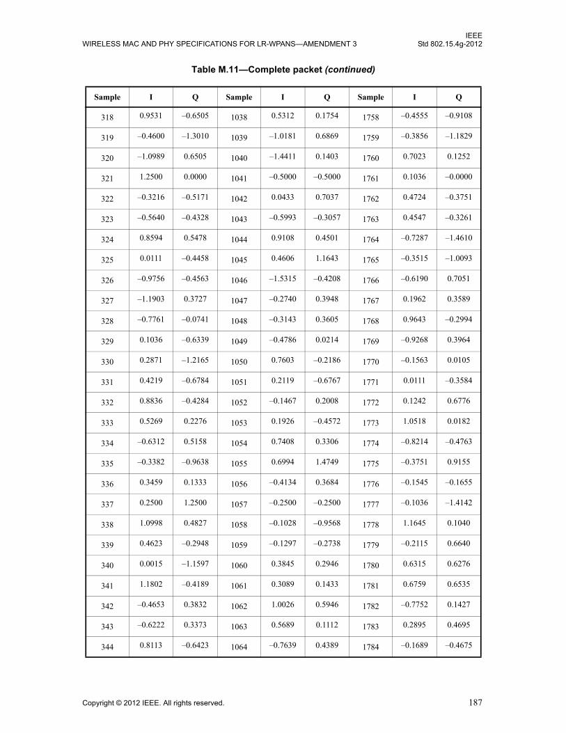
IEEEWIRELESS MAC AND PHY SPECIFICATIONS FOR LR-WPANS—AMENDMENT 3 Std 802.15.4g-2012
318 0.9531 –0.6505 1038 0.5312 0.1754 1758 –0.4555 –0.9108
319 –0.4600 –1.3010 1039 –1.0181 0.6869 1759 –0.3856 –1.1829
320 –1.0989 0.6505 1040 –1.4411 0.1403 1760 0.7023 0.1252
321 1.2500 0.0000 1041 –0.5000 –0.5000 1761 0.1036 –0.0000
322 –0.3216 –0.5171 1042 0.0433 0.7037 1762 0.4724 –0.3751
323 –0.5640 –0.4328 1043 –0.5993 –0.3057 1763 0.4547 –0.3261
324 0.8594 0.5478 1044 0.9108 0.4501 1764 –0.7287 –1.4610
325 0.0111 –0.4458 1045 0.4606 1.1643 1765 –0.3515 –1.0093
326 –0.9756 –0.4563 1046 –1.5315 –0.4208 1766 –0.6190 0.7051
327 –1.1903 0.3727 1047 –0.2740 0.3948 1767 0.1962 0.3589
328 –0.7761 –0.0741 1048 –0.3143 0.3605 1768 0.9643 –0.2994
329 0.1036 –0.6339 1049 –0.4786 0.0214 1769 –0.9268 0.3964
330 0.2871 –1.2165 1050 0.7603 –0.2186 1770 –0.1563 0.0105
331 0.4219 –0.6784 1051 0.2119 –0.6767 1771 0.0111 –0.3584
332 0.8836 –0.4284 1052 –0.1467 0.2008 1772 0.1242 0.6776
333 0.5269 0.2276 1053 0.1926 –0.4572 1773 1.0518 0.0182
334 –0.6312 0.5158 1054 0.7408 0.3306 1774 –0.8214 –0.4763
335 –0.3382 –0.9638 1055 0.6994 1.4749 1775 –0.3751 0.9155
336 0.3459 0.1333 1056 –0.4134 0.3684 1776 –0.1545 –0.1655
337 0.2500 1.2500 1057 –0.2500 –0.2500 1777 –0.1036 –1.4142
338 1.0998 0.4827 1058 –0.1028 –0.9568 1778 1.1645 0.1040
339 0.4623 –0.2948 1059 –0.1297 –0.2738 1779 –0.2115 0.6640
340 0.0015 –1.1597 1060 0.3845 0.2946 1780 0.6315 0.6276
341 1.1802 –0.4189 1061 0.3089 0.1433 1781 0.6759 0.6535
342 –0.4653 0.3832 1062 1.0026 0.5946 1782 –0.7752 0.1427
343 –0.6222 0.3373 1063 0.5689 0.1112 1783 0.2895 0.4695
344 0.8113 –0.6423 1064 –0.7639 0.4389 1784 –0.1689 –0.4675
Table M.11—Complete packet (continued)
Sample I Q Sample I Q Sample I Q
Copyright © 2012 IEEE. All rights reserved. 187

IEEEStd 802.15.4g-2012 LOCAL AND METROPOLITAN AREA NETWORKS—PART 15.4:
345 –0.6036 –1.1339 1065 –0.0947 0.0518 1785 –0.2197 –1.3536
346 –0.5391 –0.2070 1066 –0.1534 0.1638 1786 –0.2627 0.1115
347 –0.3165 –1.0258 1067 –0.6016 1.1947 1787 –0.4182 –0.0851
348 –0.5326 –0.3518 1068 –0.1063 –0.3402 1788 0.3393 –0.5796
349 0.2817 0.9077 1069 0.2883 –0.2532 1789 –1.0518 0.5245
350 –0.5541 –0.4205 1070 1.3605 0.0830 1790 –0.6281 0.0242
351 0.1470 –0.1780 1071 1.3150 –0.8342 1791 0.8118 –0.1118
352 0.5069 0.5395 1072 0.0962 –0.1351 1792 0.1943 0.5782
353 –0.7500 0.0000 1073 –0.2500 –0.7500 1793 0.1036 –0.3536
354 0.5069 –0.5395 1074 –0.2277 –1.2176 1794 0.2662 –0.9852
355 0.1470 0.1780 1075 0.2906 –0.0769 1795 0.0390 –0.5212
356 –0.5541 0.4205 1076 0.2231 0.2429 1796 0.1288 0.4527
357 0.2817 –0.9077 1077 –0.7106 0.6463 1797 0.9551 0.7593
358 –0.5326 0.3518 1078 –0.5849 1.4918 1798 0.5840 –0.5119
359 –0.3165 1.0258 1079 0.1879 0.9461 1799 0.4888 –1.0148
360 –0.5391 0.2070 1080 0.6471 0.2784 1800 1.6653 –0.9633
361 –0.6036 1.1339 1081 0.2286 0.7286 1801 0.5732 –0.6036
362 0.8113 0.6423 1082 –0.6522 –0.4000 1802 –0.1919 0.9974
363 –0.6222 –0.3373 1083 –0.2499 –0.2472 1803 –0.4793 0.4731
364 –0.4653 –0.3832 1084 0.7008 1.4607 1804 –0.6392 –0.9603
365 1.1802 0.4189 1085 0.0574 0.0608 1805 1.0518 –0.0611
366 0.0015 1.1597 1086 –1.1170 –0.4262 1806 0.1206 –0.0270
367 0.4623 0.2948 1087 –0.1905 0.4146 1807 –1.2084 –0.6095
368 1.0998 –0.4827 1088 1.3676 –0.5382 1808 0.1610 0.2443
369 0.2500 –1.2500 1089 0.5000 –1.0000 1809 0.6036 0.3536
370 0.3459 –0.1333 1090 –1.2488 –0.0071 1810 –0.0330 –0.3208
371 –0.3382 0.9638 1091 –0.5616 0.6565 1811 –0.4893 –0.3168
Table M.11—Complete packet (continued)
Sample I Q Sample I Q Sample I Q
188 Copyright © 2012 IEEE. All rights reserved.
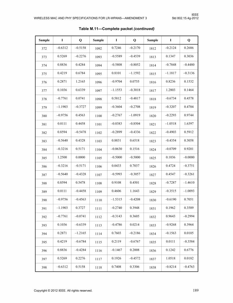
IEEEWIRELESS MAC AND PHY SPECIFICATIONS FOR LR-WPANS—AMENDMENT 3 Std 802.15.4g-2012
372 –0.6312 –0.5158 1092 0.7246 –0.2170 1812 –0.2124 0.2686
373 0.5269 –0.2276 1093 –0.5589 –0.4539 1813 0.1347 0.3036
374 0.8836 0.4284 1094 –0.5808 –0.8052 1814 –0.7848 –0.4480
375 0.4219 0.6784 1095 0.8101 –1.1592 1815 –1.1817 –0.3136
376 0.2871 1.2165 1096 –0.9704 0.0755 1816 0.8236 0.1532
377 0.1036 0.6339 1097 –1.1553 –0.3018 1817 1.2803 0.1464
378 –0.7761 0.0741 1098 0.5812 –0.4817 1818 –0.6734 0.4578
379 –1.1903 –0.3727 1099 –0.3604 –0.2708 1819 –0.3207 0.4704
380 –0.9756 0.4563 1100 –0.2767 –1.0919 1820 –0.2293 0.9744
381 0.0111 0.4458 1101 –0.0383 –0.8504 1821 –1.0518 1.6397
382 0.8594 –0.5478 1102 –0.2899 –0.4336 1822 –0.4903 0.5912
383 –0.5640 0.4328 1103 0.8831 0.6518 1823 –0.4354 0.3058
384 –0.3216 0.5171 1104 –0.0630 0.1516 1824 –0.0709 0.9201
385 1.2500 0.0000 1105 –0.5000 –0.5000 1825 0.1036 –0.0000
386 –0.3216 –0.5171 1106 0.0433 0.7037 1826 0.4724 –0.3751
387 –0.5640 –0.4328 1107 –0.5993 –0.3057 1827 0.4547 –0.3261
388 0.8594 0.5478 1108 0.9108 0.4501 1828 –0.7287 –1.4610
389 0.0111 –0.4458 1109 0.4606 1.1643 1829 –0.3515 –1.0093
390 –0.9756 –0.4563 1110 –1.5315 –0.4208 1830 –0.6190 0.7051
391 –1.1903 0.3727 1111 –0.2740 0.3948 1831 0.1962 0.3589
392 –0.7761 –0.0741 1112 –0.3143 0.3605 1832 0.9643 –0.2994
393 0.1036 –0.6339 1113 –0.4786 0.0214 1833 –0.9268 0.3964
394 0.2871 –1.2165 1114 0.7603 –0.2186 1834 –0.1563 0.0105
395 0.4219 –0.6784 1115 0.2119 –0.6767 1835 0.0111 –0.3584
396 0.8836 –0.4284 1116 –0.1467 0.2008 1836 0.1242 0.6776
397 0.5269 0.2276 1117 0.1926 –0.4572 1837 1.0518 0.0182
398 –0.6312 0.5158 1118 0.7408 0.3306 1838 –0.8214 –0.4763
Table M.11—Complete packet (continued)
Sample I Q Sample I Q Sample I Q
Copyright © 2012 IEEE. All rights reserved. 189

IEEEStd 802.15.4g-2012 LOCAL AND METROPOLITAN AREA NETWORKS—PART 15.4:
399 –0.3382 –0.9638 1119 0.6994 1.4749 1839 –0.3751 0.9155
400 0.3459 0.1333 1120 –0.4134 0.3684 1840 –0.1545 –0.1655
401 0.2500 1.2500 1121 0.4268 0.0000 1841 –0.1768 –0.1768
402 1.0998 0.4827 1122 0.9942 0.2744 1842 0.2057 0.2223
403 0.4623 –0.2948 1123 0.8211 0.9934 1843 1.2373 –0.9499
404 0.0015 –1.1597 1124 –0.5579 –0.7145 1844 0.2553 0.7366
405 1.1802 –0.4189 1125 0.5426 –0.8084 1845 –0.7106 0.7312
406 –0.4653 0.3832 1126 0.0999 0.2365 1846 –0.2716 0.5028
407 –0.6222 0.3373 1127 0.6684 –0.2380 1847 0.0209 0.2484
408 0.8113 –0.6423 1128 0.9068 –0.3356 1848 –0.2528 –0.9689
409 –0.6036 –1.1339 1129 –1.0089 0.6250 1849 0.0214 0.4786
410 –0.5391 –0.2070 1130 –0.6357 0.4815 1850 0.3021 0.5310
411 –0.3165 –1.0258 1131 –0.0194 –0.6036 1851 –0.5490 0.3853
412 –0.5326 –0.3518 1132 –0.3315 –0.4134 1852 –0.2408 0.9165
413 0.2817 0.9077 1133 –1.1746 –0.0325 1853 0.6625 –0.6419
414 –0.5541 –0.4205 1134 –1.1141 –0.1848 1854 –0.1478 –0.8287
415 0.1470 –0.1780 1135 0.4767 0.3437 1855 –0.8396 0.4183
416 0.5069 0.5395 1136 1.4635 0.9359 1856 –0.9431 0.5037
417 –0.7500 0.0000 1137 1.1642 0.8839 1857 –0.3536 –0.7071
418 0.5069 –0.5395 1138 0.2222 –0.1226 1858 –0.0471 –0.4611
419 0.1470 0.1780 1139 1.2852 –0.7261 1859 –0.8091 0.2708
420 –0.5541 0.4205 1140 0.2144 0.1598 1860 0.2917 –0.0909
421 0.2817 –0.9077 1141 –1.8866 0.4675 1861 0.5589 1.0515
422 –0.5326 0.3518 1142 0.8386 –0.0904 1862 –1.0034 0.7154
423 –0.3165 1.0258 1143 0.8794 –0.2545 1863 –0.4469 –0.3087
424 –0.5391 0.2070 1144 –0.9852 0.0991 1864 –0.3645 0.5322
425 –0.6036 1.1339 1145 –0.4482 0.1250 1865 –0.8321 0.6250
Table M.11—Complete packet (continued)
Sample I Q Sample I Q Sample I Q
190 Copyright © 2012 IEEE. All rights reserved.
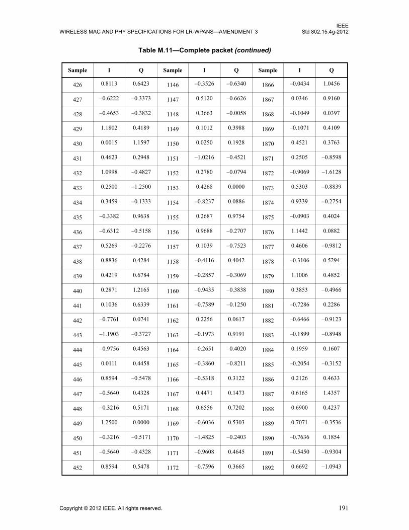
IEEEWIRELESS MAC AND PHY SPECIFICATIONS FOR LR-WPANS—AMENDMENT 3 Std 802.15.4g-2012
426 0.8113 0.6423 1146 –0.3526 –0.6340 1866 –0.0434 1.0456
427 –0.6222 –0.3373 1147 0.5120 –0.6626 1867 0.0346 0.9160
428 –0.4653 –0.3832 1148 0.3663 –0.0058 1868 –0.1049 0.0397
429 1.1802 0.4189 1149 0.1012 0.3988 1869 –0.1071 0.4109
430 0.0015 1.1597 1150 0.0250 0.1928 1870 0.4521 0.3763
431 0.4623 0.2948 1151 –1.0216 –0.4521 1871 0.2505 –0.8598
432 1.0998 –0.4827 1152 0.2780 –0.0794 1872 –0.9069 –1.6128
433 0.2500 –1.2500 1153 0.4268 0.0000 1873 0.5303 –0.8839
434 0.3459 –0.1333 1154 –0.8237 0.0886 1874 0.9339 –0.2754
435 –0.3382 0.9638 1155 0.2687 0.9754 1875 –0.0903 0.4024
436 –0.6312 –0.5158 1156 0.9688 –0.2707 1876 1.1442 0.0882
437 0.5269 –0.2276 1157 0.1039 –0.7523 1877 0.4606 –0.9812
438 0.8836 0.4284 1158 –0.4116 0.4042 1878 –0.3106 0.5294
439 0.4219 0.6784 1159 –0.2857 –0.3069 1879 1.1006 0.4852
440 0.2871 1.2165 1160 –0.9435 –0.3838 1880 0.3853 –0.4966
441 0.1036 0.6339 1161 –0.7589 –0.1250 1881 –0.7286 0.2286
442 –0.7761 0.0741 1162 0.2256 0.0617 1882 –0.6466 –0.9123
443 –1.1903 –0.3727 1163 –0.1973 0.9191 1883 –0.1899 –0.8948
444 –0.9756 0.4563 1164 –0.2651 –0.4020 1884 0.1959 0.1607
445 0.0111 0.4458 1165 –0.3860 –0.8211 1885 –0.2054 –0.3152
446 0.8594 –0.5478 1166 –0.5318 0.3122 1886 0.2126 0.4633
447 –0.5640 0.4328 1167 0.4471 0.1473 1887 0.6165 1.4357
448 –0.3216 0.5171 1168 0.6556 0.7202 1888 0.6900 0.4237
449 1.2500 0.0000 1169 –0.6036 0.5303 1889 0.7071 –0.3536
450 –0.3216 –0.5171 1170 –1.4825 –0.2403 1890 –0.7636 0.1854
451 –0.5640 –0.4328 1171 –0.9608 0.4645 1891 –0.5450 –0.9304
452 0.8594 0.5478 1172 –0.7596 0.3665 1892 0.6692 –1.0943
Table M.11—Complete packet (continued)
Sample I Q Sample I Q Sample I Q
Copyright © 2012 IEEE. All rights reserved. 191

IEEEStd 802.15.4g-2012 LOCAL AND METROPOLITAN AREA NETWORKS—PART 15.4:
453 0.0111 –0.4458 1173 –0.1741 –0.3211 1893 –0.3089 0.6127
454 –0.9756 –0.4563 1174 –0.3101 –0.5504 1894 –0.3160 0.1540
455 –1.1903 0.3727 1175 –1.2621 0.0923 1895 0.5325 –0.2178
456 –0.7761 –0.0741 1176 0.4985 0.3137 1896 0.2097 –1.0443
457 0.1036 –0.6339 1177 0.8018 –0.6250 1897 –0.5821 –0.6250
458 0.2871 –1.2165 1178 0.4383 0.0908 1898 –1.3552 1.0788
459 0.4219 –0.6784 1179 1.1190 0.0542 1899 –0.5029 –0.6137
460 0.8836 –0.4284 1180 –0.2210 –0.7201 1900 1.2036 –0.1707
461 0.5269 0.2276 1181 0.0452 0.4548 1901 1.0642 0.5462
462 –0.6312 0.5158 1182 –0.0100 –0.3203 1902 –0.0295 –0.4982
463 –0.3382 –0.9638 1183 0.0977 –0.7461 1903 0.1797 0.2128
464 0.3459 0.1333 1184 1.5405 0.7300 1904 0.5965 –0.7512
465 0.2500 1.2500 1185 0.4268 0.0000 1905 –0.1768 –0.1768
466 1.0998 0.4827 1186 0.9942 0.2744 1906 0.2057 0.2223
467 0.4623 –0.2948 1187 0.8211 0.9934 1907 1.2373 –0.9499
468 0.0015 –1.1597 1188 –0.5579 –0.7145 1908 0.2553 0.7366
469 1.1802 –0.4189 1189 0.5426 –0.8084 1909 –0.7106 0.7312
470 –0.4653 0.3832 1190 0.0999 0.2365 1910 –0.2716 0.5028
471 –0.6222 0.3373 1191 0.6684 –0.2380 1911 0.0209 0.2484
472 0.8113 –0.6423 1192 0.9068 –0.3356 1912 –0.2528 –0.9689
473 –0.6036 –1.1339 1193 –1.0089 0.6250 1913 0.0214 0.4786
474 –0.5391 –0.2070 1194 –0.6357 0.4815 1914 0.3021 0.5310
475 –0.3165 –1.0258 1195 –0.0194 –0.6036 1915 –0.5490 0.3853
476 –0.5326 –0.3518 1196 –0.3315 –0.4134 1916 –0.2408 0.9165
477 0.2817 0.9077 1197 –1.1746 –0.0325 1917 0.6625 –0.6419
478 –0.5541 –0.4205 1198 –1.1141 –0.1848 1918 –0.1478 –0.8287
479 0.1470 –0.1780 1199 0.4767 0.3437 1919 –0.8396 0.4183
Table M.11—Complete packet (continued)
Sample I Q Sample I Q Sample I Q
192 Copyright © 2012 IEEE. All rights reserved.

IEEEWIRELESS MAC AND PHY SPECIFICATIONS FOR LR-WPANS—AMENDMENT 3 Std 802.15.4g-2012
480 0.5069 0.5395 1200 1.4635 0.9359 1920 –0.9431 0.5037
481 0.7500 –0.2500 1201 –0.3536 0.3536 1921 –0.8839 –0.0000
482 0.0030 0.0383 1202 –0.6225 0.5404 1922 –0.5281 0.5001
483 –0.4024 0.3583 1203 –0.1716 –0.2718 1923 –0.0039 0.6801
484 1.1517 0.1295 1204 –1.1936 0.9375 1924 –0.5595 0.8308
485 –0.3571 –0.3694 1205 0.0378 0.0018 1925 –0.7917 0.7297
486 –0.7863 0.3638 1206 0.6464 –1.0822 1926 0.0089 –0.0110
487 1.0069 –0.1142 1207 –0.3420 –0.3460 1927 –0.3694 0.3613
488 –0.5347 –0.4360 1208 –0.1094 0.6579 1928 1.2119 –0.1508
489 –0.3750 0.6250 1209 –0.7071 0.9268 1929 0.9786 0.1982
490 1.1394 0.9180 1210 –0.5974 0.1001 1930 –0.9843 0.0442
491 0.4178 –0.2132 1211 –0.1627 0.0859 1931 0.3119 –1.3171
492 0.5319 –1.1776 1212 –0.4667 –0.1517 1932 0.4241 0.2268
493 –0.1049 –0.8631 1213 0.0621 –0.1260 1933 0.2341 0.8348
494 –0.7085 –0.4467 1214 –0.8100 –0.1574 1934 0.5149 0.4050
495 –0.2948 0.2850 1215 –0.1639 –0.7336 1935 –0.5881 0.7871
496 –0.9447 0.4838 1216 1.8775 0.1407 1936 0.1107 –0.0131
497 –1.0000 0.0000 1217 0.0000 0.3536 1937 0.7071 –0.1768
498 –0.9515 –0.5292 1218 –0.8706 0.3725 1938 –0.2172 0.4891
499 –0.2478 –0.8458 1219 0.7309 0.9490 1939 0.3772 0.5686
500 0.3843 0.4523 1220 0.9331 0.5853 1940 1.1447 –0.7164
501 –0.9125 0.2151 1221 1.2651 –0.0004 1941 0.1512 –0.9046
502 –0.1435 –0.6271 1222 1.0011 –0.8286 1942 –0.1850 0.3940
503 0.3474 0.3114 1223 0.1323 –1.1359 1943 –0.4407 –0.6066
504 –0.8656 0.3428 1224 0.4767 –0.4300 1944 –1.0693 –0.4243
505 0.3018 –0.0518 1225 0.3536 0.1768 1945 0.4786 1.1982
506 0.2228 –0.7921 1226 –0.1387 –0.3935 1946 0.2871 –0.0292
Table M.11—Complete packet (continued)
Sample I Q Sample I Q Sample I Q
Copyright © 2012 IEEE. All rights reserved. 193
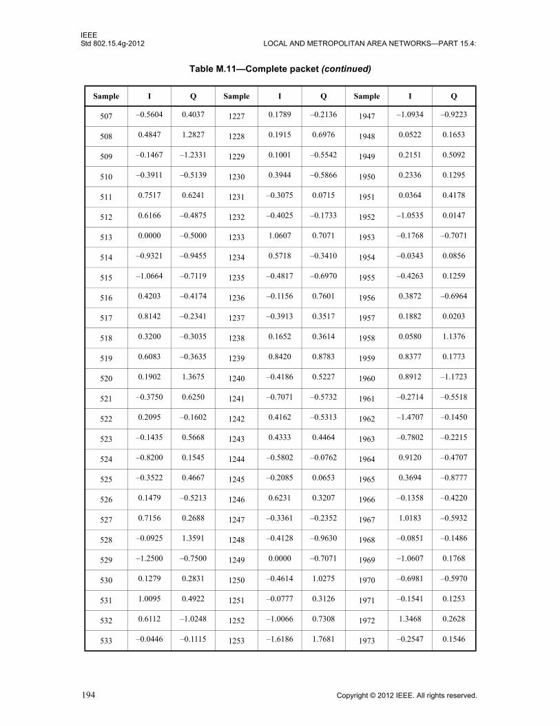
IEEEStd 802.15.4g-2012 LOCAL AND METROPOLITAN AREA NETWORKS—PART 15.4:
507 –0.5604 0.4037 1227 0.1789 –0.2136 1947 –1.0934 –0.9223
508 0.4847 1.2827 1228 0.1915 0.6976 1948 0.0522 0.1653
509 –0.1467 –1.2331 1229 0.1001 –0.5542 1949 0.2151 0.5092
510 –0.3911 –0.5139 1230 0.3944 –0.5866 1950 0.2336 0.1295
511 0.7517 0.6241 1231 –0.3075 0.0715 1951 0.0364 0.4178
512 0.6166 –0.4875 1232 –0.4025 –0.1733 1952 –1.0535 0.0147
513 0.0000 –0.5000 1233 1.0607 0.7071 1953 –0.1768 –0.7071
514 –0.9321 –0.9455 1234 0.5718 –0.3410 1954 –0.0343 0.0856
515 –1.0664 –0.7119 1235 –0.4817 –0.6970 1955 –0.4263 0.1259
516 0.4203 –0.4174 1236 –0.1156 0.7601 1956 0.3872 –0.6964
517 0.8142 –0.2341 1237 –0.3913 0.3517 1957 0.1882 0.0203
518 0.3200 –0.3035 1238 0.1652 0.3614 1958 0.0580 1.1376
519 0.6083 –0.3635 1239 0.8420 0.8783 1959 0.8377 0.1773
520 0.1902 1.3675 1240 –0.4186 0.5227 1960 0.8912 –1.1723
521 –0.3750 0.6250 1241 –0.7071 –0.5732 1961 –0.2714 –0.5518
522 0.2095 –0.1602 1242 0.4162 –0.5313 1962 –1.4707 –0.1450
523 –0.1435 0.5668 1243 0.4333 0.4464 1963 –0.7802 –0.2215
524 –0.8200 0.1545 1244 –0.5802 –0.0762 1964 0.9120 –0.4707
525 –0.3522 0.4667 1245 –0.2085 0.0653 1965 0.3694 –0.8777
526 0.1479 –0.5213 1246 0.6231 0.3207 1966 –0.1358 –0.4220
527 0.7156 0.2688 1247 –0.3361 –0.2352 1967 1.0183 –0.5932
528 –0.0925 1.3591 1248 –0.4128 –0.9630 1968 –0.0851 –0.1486
529 –1.2500 –0.7500 1249 0.0000 –0.7071 1969 –1.0607 0.1768
530 0.1279 0.2831 1250 –0.4614 1.0275 1970 –0.6981 –0.5970
531 1.0095 0.4922 1251 –0.0777 0.3126 1971 –0.1541 0.1253
532 0.6112 –1.0248 1252 –1.0066 0.7308 1972 1.3468 0.2628
533 –0.0446 –0.1115 1253 –1.6186 1.7681 1973 –0.2547 0.1546
Table M.11—Complete packet (continued)
Sample I Q Sample I Q Sample I Q
194 Copyright © 2012 IEEE. All rights reserved.

IEEEWIRELESS MAC AND PHY SPECIFICATIONS FOR LR-WPANS—AMENDMENT 3 Std 802.15.4g-2012
534 –1.4091 –0.2039 1254 0.1112 –0.6989 1974 –0.7423 0.3398
535 –0.9626 –0.2479 1255 0.3677 –1.1035 1975 1.1795 –0.4320
536 0.0253 0.2034 1256 0.1275 –0.5023 1976 –0.2495 –1.0368
537 –0.0518 0.3018 1257 0.3536 0.1768 1977 0.2286 –1.5518
538 0.5953 0.1876 1258 –0.2974 –0.1890 1978 1.2315 0.0664
539 0.9932 –0.0501 1259 –0.4495 –2.0258 1979 0.3546 0.9608
540 1.0643 0.1866 1260 0.2381 –0.0692 1980 0.7067 –0.0164
541 1.1038 0.1295 1261 0.7534 –0.0923 1981 –0.1115 0.9479
542 0.5564 1.2525 1262 –0.1313 –0.7426 1982 –0.1665 0.4414
543 –0.1725 1.2363 1263 –0.1925 1.1902 1983 –0.2595 –0.1117
544 –0.2230 –0.4189 1264 0.8617 0.1615 1984 –1.3421 0.5170
545 0.7500 –0.2500 1265 –0.3536 0.3536 1985 –0.8839 –0.0000
546 0.0030 0.0383 1266 –0.6225 0.5404 1986 –0.5281 0.5001
547 –0.4024 0.3583 1267 –0.1716 –0.2718 1987 –0.0039 0.6801
548 1.1517 0.1295 1268 –1.1936 0.9375 1988 –0.5595 0.8308
549 –0.3571 –0.3694 1269 0.0378 0.0018 1989 –0.7917 0.7297
550 –0.7863 0.3638 1270 0.6464 –1.0822 1990 0.0089 –0.0110
551 1.0069 –0.1142 1271 –0.3420 –0.3460 1991 –0.3694 0.3613
552 –0.5347 –0.4360 1272 –0.1094 0.6579 1992 1.2119 –0.1508
553 –0.3750 0.6250 1273 –0.7071 0.9268 1993 0.9786 0.1982
554 1.1394 0.9180 1274 –0.5974 0.1001 1994 –0.9843 0.0442
555 0.4178 –0.2132 1275 –0.1627 0.0859 1995 0.3119 –1.3171
556 0.5319 –1.1776 1276 –0.4667 –0.1517 1996 0.4241 0.2268
557 –0.1049 –0.8631 1277 0.0621 –0.1260 1997 0.2341 0.8348
558 –0.7085 –0.4467 1278 –0.8100 –0.1574 1998 0.5149 0.4050
559 –0.2948 0.2850 1279 –0.1639 –0.7336 1999 –0.5881 0.7871
560 –0.9447 0.4838 1280 1.8775 0.1407 2000 0.1107 –0.0131
Table M.11—Complete packet (continued)
Sample I Q Sample I Q Sample I Q
Copyright © 2012 IEEE. All rights reserved. 195

IEEEStd 802.15.4g-2012 LOCAL AND METROPOLITAN AREA NETWORKS—PART 15.4:
561 0.5000 0.0000 1281 0.8839 0.5303 2001 –0.4268 0.3536
562 –0.3085 –0.2892 1282 0.5424 –0.0022 2002 –1.0574 –0.1440
563 –0.1437 –0.2565 1283 –0.5860 –0.5003 2003 –0.7470 0.4266
564 –0.1802 0.2279 1284 0.4166 0.2304 2004 0.3722 1.3037
565 0.2839 –0.2244 1285 1.3276 –0.4516 2005 –0.1084 0.3042
566 –0.8160 –0.8546 1286 0.1451 –0.7357 2006 –1.1934 –0.5430
567 –1.6074 0.3079 1287 0.3228 0.1189 2007 –0.3996 –0.1660
568 0.7877 –0.1511 1288 –0.6096 0.6574 2008 0.6821 –0.6570
569 0.3750 –0.8321 1289 –1.0303 0.7071 2009 –0.1768 –0.3232
570 –0.9921 –0.2920 1290 0.1291 –1.0814 2010 –1.9805 0.3039
571 –0.0893 –0.4812 1291 0.2828 –0.7487 2011 –1.1431 –0.8739
572 –0.1895 0.4323 1292 –0.0971 0.7849 2012 1.0910 –0.3047
573 0.3314 1.4226 1293 –0.8863 –0.8433 2013 0.7119 0.0045
574 0.4784 0.5251 1294 0.2760 –0.4223 2014 0.5305 –0.1432
575 0.1954 –0.1440 1295 1.1043 0.1005 2015 1.1243 0.7097
576 1.1669 0.2835 1296 0.0984 –0.8117 2016 –0.4017 –0.5379
577 0.7500 –0.2500 1297 0.5303 1.2374 2017 –0.6339 0.7071
578 0.7536 0.0435 1298 0.6691 0.9030 2018 0.8179 1.2678
579 0.5296 0.7304 1299 0.0706 –0.6003 2019 0.7275 –1.0177
580 –0.6150 –1.1478 1300 –0.4665 0.5808 2020 0.4730 0.1557
581 0.4857 –0.2386 1301 –0.9180 0.2603 2021 0.1622 –0.3311
582 0.3202 1.5452 1302 –1.1723 –0.3012 2022 –0.6697 –0.8676
583 –0.0228 0.2686 1303 –0.9438 –0.5155 2023 –0.6594 0.1583
584 1.5213 0.2369 1304 –0.0858 –0.4900 2024 –0.4641 –0.8158
585 0.4053 0.0518 1305 0.0732 0.6464 2025 –0.6768 0.5732
586 –0.7148 0.3455 1306 0.4904 0.5272 2026 –0.8257 1.1738
587 0.0196 0.6050 1307 –0.3957 0.3213 2027 –0.6350 –0.2757
Table M.11—Complete packet (continued)
Sample I Q Sample I Q Sample I Q
196 Copyright © 2012 IEEE. All rights reserved.

IEEEWIRELESS MAC AND PHY SPECIFICATIONS FOR LR-WPANS—AMENDMENT 3 Std 802.15.4g-2012
588 –0.0255 –0.6389 1308 –0.9791 0.1224 2028 –0.5510 –0.6712
589 –0.1971 0.1324 1309 0.3974 –0.0552 2029 –0.4413 –0.4395
590 –0.3794 0.3976 1310 –0.9349 0.8005 2030 0.8945 0.4371
591 0.1334 –0.3895 1311 –0.6716 0.3852 2031 1.3260 0.3028
592 0.3540 –0.6079 1312 1.0813 0.1325 2032 0.1681 0.5123
593 –0.7500 0.2500 1313 0.5303 0.5303 2033 0.2803 0.0000
594 –0.2563 1.2112 1314 0.8554 0.2168 2034 –0.1132 0.0082
595 0.2901 –0.0178 1315 –0.3734 –0.1593 2035 –1.0167 1.3556
596 –0.9078 0.3924 1316 –0.8737 –0.7140 2036 0.2982 –0.4010
597 –0.8874 0.1815 1317 0.4830 0.2016 2037 0.8155 –0.1577
598 –0.0706 –1.4117 1318 0.0811 0.1980 2038 0.2434 0.3889
599 0.4541 –0.2286 1319 0.2158 –1.1283 2039 0.8186 –1.3076
600 1.2821 0.3947 1320 –0.0028 0.3368 2040 0.4914 0.0773
601 0.3750 0.5821 1321 –0.0303 0.7071 2041 –0.1768 0.1768
602 –0.7421 –0.0435 1322 0.4445 0.1774 2042 0.3101 –0.5701
603 0.9429 –0.2804 1323 0.1025 0.5099 2043 0.4566 –0.3089
604 1.0435 0.7421 1324 0.4375 –1.5122 2044 –0.0392 –0.4203
605 –0.7278 –0.6726 1325 –0.4244 –1.1139 2045 –0.2119 0.8491
606 –0.2412 0.0818 1326 –1.4370 1.1767 2046 0.5225 0.9202
607 –0.4248 1.2592 1327 –0.5277 0.3932 2047 0.7947 0.2765
608 –0.6098 0.2982 1328 0.2555 0.4147 2048 0.0461 –0.4595
609 1.0000 0.5000 1329 –0.5303 1.2374 2049 0.0732 –1.0607
610 0.3883 –0.6949 1330 –0.7963 0.6254 2050 0.1815 –0.1955
611 –0.3832 –1.1632 1331 0.3888 0.0528 2051 0.1220 0.0283
612 0.2529 –1.0497 1332 –0.1884 –0.1511 2052 0.7169 –0.0711
613 –0.3821 –1.2185 1333 –0.1855 –0.0103 2053 0.5449 –0.5224
614 –0.5456 0.0679 1334 0.5994 0.3515 2054 0.2181 0.5755
Table M.11—Complete packet (continued)
Sample I Q Sample I Q Sample I Q
Copyright © 2012 IEEE. All rights reserved. 197

IEEEStd 802.15.4g-2012 LOCAL AND METROPOLITAN AREA NETWORKS—PART 15.4:
615 0.1761 –0.3479 1335 –0.0948 0.3178 2055 0.1546 1.5224
616 0.0176 –0.5926 1336 0.1211 –0.9407 2056 –0.2317 –0.8476
617 –0.6553 –0.3018 1337 –0.4268 –1.3536 2057 0.3232 –0.4268
618 –0.1281 –0.2806 1338 –0.3345 0.0480 2058 0.2530 0.5701
619 0.8339 0.8637 1339 0.5104 –0.2895 2059 –0.5927 –0.7486
620 –0.2068 1.0417 1340 –0.2493 –0.7555 2060 0.0531 –0.0054
621 –0.9064 0.6176 1341 0.2061 0.5981 2061 –0.0587 0.2930
622 –0.7457 –0.3512 1342 0.4426 0.3467 2062 –0.9602 –0.3537
623 –0.9040 –0.7257 1343 0.5950 –1.0860 2063 –0.3308 –0.0820
624 0.3086 0.1382 1344 1.1419 –0.7133 2064 0.1240 0.3139
625 0.5000 0.0000 1345 0.8839 0.5303 2065 –0.4268 0.3536
626 –0.3085 –0.2892 1346 0.5424 –0.0022 2066 –1.0574 –0.1440
627 –0.1437 –0.2565 1347 –0.5860 –0.5003 2067 –0.7470 0.4266
628 –0.1802 0.2279 1348 0.4166 0.2304 2068 0.3722 1.3037
629 0.2839 –0.2244 1349 1.3276 –0.4516 2069 –0.1084 0.3042
630 –0.8160 –0.8546 1350 0.1451 –0.7357 2070 –1.1934 –0.5430
631 –1.6074 0.3079 1351 0.3228 0.1189 2071 –0.3996 –0.1660
632 0.7877 –0.1511 1352 –0.6096 0.6574 2072 0.6821 –0.6570
633 0.3750 –0.8321 1353 –1.0303 0.7071 2073 –0.1768 –0.3232
634 –0.9921 –0.2920 1354 0.1291 –1.0814 2074 –1.9805 0.3039
635 –0.0893 –0.4812 1355 0.2828 –0.7487 2075 –1.1431 –0.8739
636 –0.1895 0.4323 1356 –0.0971 0.7849 2076 1.0910 –0.3047
637 0.3314 1.4226 1357 –0.8863 –0.8433 2077 0.7119 0.0045
638 0.4784 0.5251 1358 0.2760 –0.4223 2078 0.5305 –0.1432
639 0.1954 –0.1440 1359 1.1043 0.1005 2079 1.1243 0.7097
640 1.1669 0.2835 1360 0.0984 –0.8117 2080 –0.4017 –0.5379
641 –0.2500 0.0000 1361 0.6036 0.1768 2081 –0.5303 –0.3536
Table M.11—Complete packet (continued)
Sample I Q Sample I Q Sample I Q
198 Copyright © 2012 IEEE. All rights reserved.

IEEEWIRELESS MAC AND PHY SPECIFICATIONS FOR LR-WPANS—AMENDMENT 3 Std 802.15.4g-2012
642 0.0992 –0.0286 1362 0.3992 –1.0879 2082 –0.2412 –1.2369
643 0.2191 –0.0721 1363 –0.5504 –0.9586 2083 0.0325 0.1695
644 –0.0967 –0.3706 1364 –0.7227 –0.5638 2084 0.4862 1.0950
645 –0.3298 –0.5272 1365 –0.6228 –0.5814 2085 0.9334 0.8104
646 –0.5840 –1.1713 1366 0.1130 –0.5003 2086 0.0086 0.4289
647 –0.5644 0.3122 1367 0.2416 0.7555 2087 –0.1074 0.2087
648 0.1361 0.8877 1368 –0.4563 0.7879 2088 0.3809 –0.8744
649 0.4053 0.4053 1369 –0.8750 –1.1553 2089 0.1982 –0.6250
650 0.4374 0.4681 1370 –1.1105 –0.0629 2090 1.0224 0.4850
651 –0.4830 –0.3086 1371 –0.1102 0.8284 2091 0.4970 –0.5663
652 –0.6867 0.3758 1372 0.3078 –0.6422 2092 –0.6378 –0.5282
653 1.2357 0.8089 1373 0.1150 –0.2262 2093 –0.3108 –0.2804
654 0.7685 –0.3674 1374 0.4227 0.4172 2094 –0.6898 0.0300
655 –0.0880 –0.0741 1375 0.8959 0.2667 2095 –0.6495 0.5202
656 0.9866 0.1074 1376 0.5364 0.2204 2096 –1.0067 –1.4767
657 0.2500 –0.5000 1377 –1.1339 –0.3536 2097 –1.7678 –0.8839
658 0.2423 0.7199 1378 0.4379 0.1646 2098 –0.6350 0.3694
659 1.0962 0.1399 1379 1.5486 1.1206 2099 –0.0401 –0.7119
660 0.0096 –1.6950 1380 –0.7839 –0.2537 2100 0.3445 –0.1592
661 –0.3425 0.7375 1381 –0.1530 –1.0100 2101 0.1146 0.2084
662 0.0573 1.0281 1382 0.8392 0.0443 2102 –0.9477 –0.1312
663 –0.1529 –0.8073 1383 0.7233 –0.1368 2103 0.4526 –0.3851
664 –0.4811 0.2484 1384 0.5130 0.0888 2104 0.5693 –0.0263
665 0.0821 –0.1250 1385 –0.4786 –0.0518 2105 –0.9053 0.2714
666 0.9896 0.6340 1386 0.3072 –0.5150 2106 –0.1578 –0.6136
667 –0.0324 1.0040 1387 0.7393 1.2424 2107 0.3078 –0.5199
668 –0.1874 –0.4979 1388 0.6595 0.9815 2108 –0.1159 –0.4045
Table M.11—Complete packet (continued)
Sample I Q Sample I Q Sample I Q
Copyright © 2012 IEEE. All rights reserved. 199
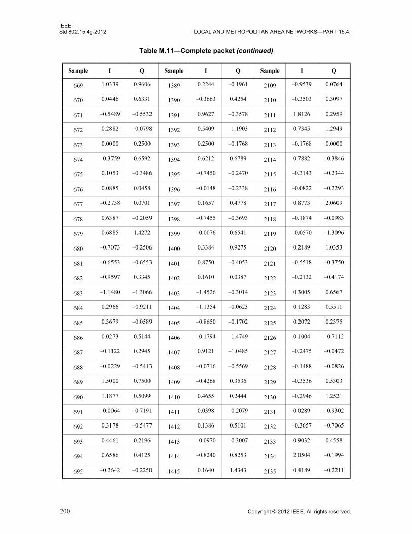
IEEEStd 802.15.4g-2012 LOCAL AND METROPOLITAN AREA NETWORKS—PART 15.4:
669 1.0339 0.9606 1389 0.2244 –0.1961 2109 –0.9539 0.0764
670 0.0446 0.6331 1390 –0.3663 0.4254 2110 –0.3503 0.3097
671 –0.5489 –0.5532 1391 0.9627 –0.3578 2111 1.8126 0.2959
672 0.2882 –0.0798 1392 0.5409 –1.1903 2112 0.7345 1.2949
673 0.0000 0.2500 1393 0.2500 –0.1768 2113 –0.1768 0.0000
674 –0.3759 0.6592 1394 0.6212 0.6789 2114 0.7882 –0.3846
675 0.1053 –0.3486 1395 –0.7450 –0.2470 2115 –0.3143 –0.2344
676 0.0885 0.0458 1396 –0.0148 –0.2338 2116 –0.0822 –0.2293
677 –0.2738 0.0701 1397 0.1657 0.4778 2117 0.8773 2.0609
678 0.6387 –0.2059 1398 –0.7455 –0.3693 2118 –0.1874 –0.0983
679 0.6885 1.4272 1399 –0.0076 0.6541 2119 –0.0570 –1.3096
680 –0.7073 –0.2506 1400 0.3384 0.9275 2120 0.2189 1.0353
681 –0.6553 –0.6553 1401 0.8750 –0.4053 2121 –0.5518 –0.3750
682 –0.9597 0.3345 1402 0.1610 0.0387 2122 –0.2132 –0.4174
683 –1.1480 –1.3066 1403 –1.4526 –0.3014 2123 0.3005 0.6567
684 0.2966 –0.9211 1404 –1.1354 –0.0623 2124 0.1283 0.5511
685 0.3679 –0.0589 1405 –0.8650 –0.1702 2125 0.2072 0.2375
686 0.0273 0.5144 1406 –0.1794 –1.4749 2126 0.1004 –0.7112
687 –0.1122 0.2945 1407 0.9121 –1.0485 2127 –0.2475 –0.0472
688 –0.0229 –0.5413 1408 –0.0716 –0.5569 2128 –0.1488 –0.0826
689 1.5000 0.7500 1409 –0.4268 0.3536 2129 –0.3536 0.5303
690 1.1877 0.5099 1410 0.4655 0.2444 2130 –0.2946 1.2521
691 –0.0064 –0.7191 1411 0.0398 –0.2079 2131 0.0289 –0.9302
692 0.3178 –0.5477 1412 0.1386 0.5101 2132 –0.3657 –0.7065
693 0.4461 0.2196 1413 –0.0970 –0.3007 2133 0.9032 0.4558
694 0.6586 0.4125 1414 –0.8240 0.8253 2134 2.0504 –0.1994
695 –0.2642 –0.2250 1415 0.1640 1.4343 2135 0.4189 –0.2211
Table M.11—Complete packet (continued)
Sample I Q Sample I Q Sample I Q
200 Copyright © 2012 IEEE. All rights reserved.

IEEEWIRELESS MAC AND PHY SPECIFICATIONS FOR LR-WPANS—AMENDMENT 3 Std 802.15.4g-2012
696 –1.7320 0.2993 1416 –0.3190 –0.4976 2136 –0.2454 –0.1345
697 –1.3321 –0.1250 1417 –0.2286 0.1982 2137 –0.1553 0.0214
698 –0.6206 –0.8828 1418 0.7183 0.5393 2138 –0.2687 0.5459
699 0.2492 –0.3888 1419 –0.8835 –0.0622 2139 0.6018 0.7224
700 0.6725 –0.2177 1420 –0.4492 0.2642 2140 0.2427 0.3816
701 –0.1374 –0.2106 1421 –0.1815 0.5925 2141 –0.3567 0.6736
702 –0.6110 –1.2578 1422 –1.2597 0.6324 2142 0.0158 0.3715
703 –0.9579 –0.3743 1423 0.3506 –0.1533 2143 –0.2085 –0.4761
704 –0.8819 1.1574 1424 0.9181 0.2202 2144 –0.5029 0.2644
705 –0.2500 0.0000 1425 0.6036 0.1768 2145 –0.5303 –0.3536
706 0.0992 –0.0286 1426 0.3992 –1.0879 2146 –0.2412 –1.2369
707 0.2191 –0.0721 1427 –0.5504 –0.9586 2147 0.0325 0.1695
708 –0.0967 –0.3706 1428 –0.7227 –0.5638 2148 0.4862 1.0950
709 –0.3298 –0.5272 1429 –0.6228 –0.5814 2149 0.9334 0.8104
710 –0.5840 –1.1713 1430 0.1130 –0.5003 2150 0.0086 0.4289
711 –0.5644 0.3122 1431 0.2416 0.7555 2151 –0.1074 0.2087
712 0.1361 0.8877 1432 –0.4563 0.7879 2152 0.3809 –0.8744
713 0.4053 0.4053 1433 –0.8750 –1.1553 2153 0.1982 –0.6250
714 0.4374 0.4681 1434 –1.1105 –0.0629 2154 1.0224 0.4850
715 –0.4830 –0.3086 1435 –0.1102 0.8284 2155 0.4970 –0.5663
716 –0.6867 0.3758 1436 0.3078 –0.6422 2156 –0.6378 –0.5282
717 1.2357 0.8089 1437 0.1150 –0.2262 2157 –0.3108 –0.2804
718 0.7685 –0.3674 1438 0.4227 0.4172 2158 –0.6898 0.0300
719 –0.0880 –0.0741 1439 0.8959 0.2667 2159 –0.6495 0.5202
720 0.9866 0.1074 1440 0.5364 0.2204 2160 –1.0067 –1.4767
Table M.11—Complete packet (continued)
Sample I Q Sample I Q Sample I Q
Copyright © 2012 IEEE. All rights reserved. 201

IEEEStd 802.15.4g-2012 LOCAL AND METROPOLITAN AREA NETWORKS—PART 15.4:
Insert after new Annex M the following new annex (Annex N):
Annex N
(informative)
Example of encoding a packet for MR-O-QPSK PHY
N.1 Introduction
The purpose of this annex is to show an example of encoding a packet for the MR-QPSK PHY, as described in 18.3. In particular, generation of the PPDU chip sequence, , is described in detail.
The frequency band used in this example is the 470 MHz band, implying a chip rate of 100 kchip/s. This example uses RateMode zero, which corresponds to a PSDU data rate of 6.25 kb/s.
The encoding illustration goes through the following stages:
a) Generating the bit sequence of the SHR
b) Applying BDE to the bit sequence
c) Applying (32,1)0-DSSS to the bit sequence to obtain the chip sequences cSHR
d) Generating the bit sequence of the PHR
e) Extending the bit sequence by appending six, zero bits
f) Encoding the bit sequence of the PHR with a rate 1/2 convolutional encoder
g) Interleaving of the code-bit sequence
h) Applying BDE to the code-bit sequence
i) Applying (8,1)0/1-DSSS to the code-bit sequence to obtain cPHR
j) Generating the bit sequence of the PSDU
k) Extending the bit sequence by appending six, zero bits and pad bits
l) Encoding the bit sequence of the PSDU with a rate 1/2 convolutional encoder
m) Interleaving of the code-bit sequence
n) Applying BDE to the code-bit sequence
o) Applying (8,1)0/1-DSSS to the code-bit sequence
p) Insertion of pilot sequences to the chip sequence of the PSDU section, obtaining the chip sequence cPSDU
q) Concatenation
In this example, all binary sequences of length n are treated as bit strings:
b0 b1 ......................... bn-1
The corresponding entries are processed b0 first to bn-1 last.
cPPDU
cPPDU cSHR cPHR cPSDU, ,{ }=
202 Copyright © 2012 IEEE. All rights reserved.
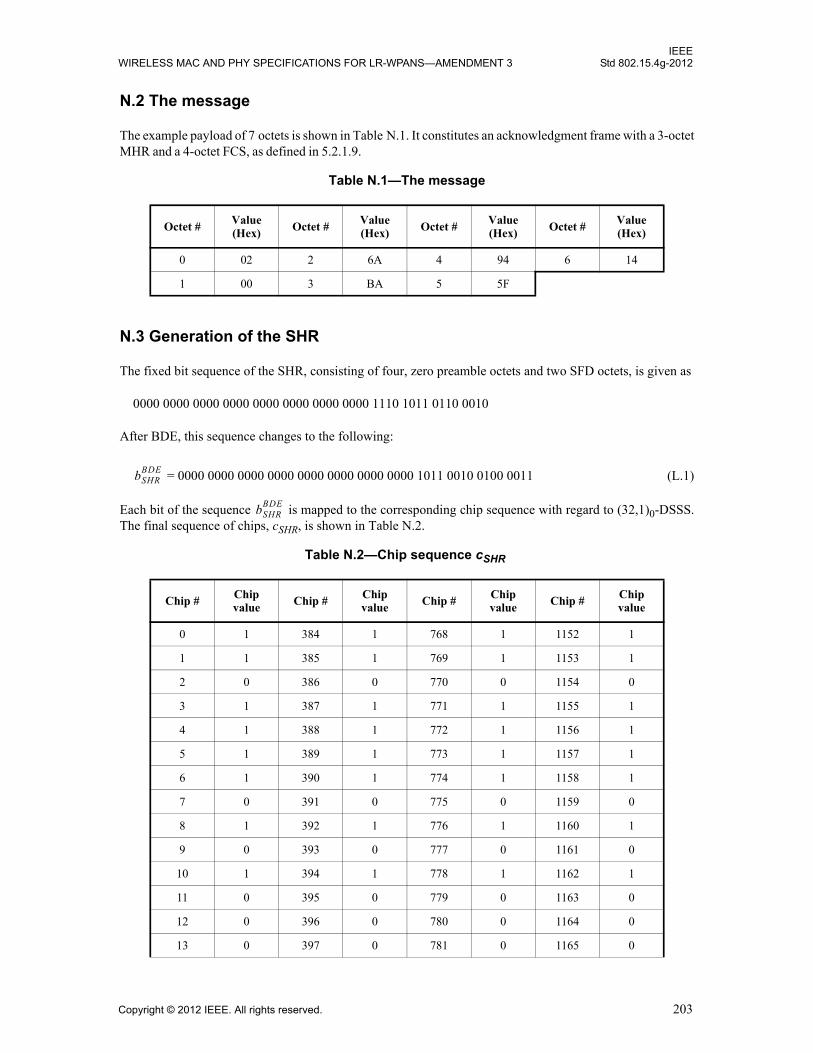
IEEEWIRELESS MAC AND PHY SPECIFICATIONS FOR LR-WPANS—AMENDMENT 3 Std 802.15.4g-2012
N.2 The message
The example payload of 7 octets is shown in Table N.1. It constitutes an acknowledgment frame with a 3-octet MHR and a 4-octet FCS, as defined in 5.2.1.9.
N.3 Generation of the SHR
The fixed bit sequence of the SHR, consisting of four, zero preamble octets and two SFD octets, is given as
0000 0000 0000 0000 0000 0000 0000 0000 1110 1011 0110 0010
After BDE, this sequence changes to the following:
= 0000 0000 0000 0000 0000 0000 0000 0000 1011 0010 0100 0011 (L.1)
Each bit of the sequence is mapped to the corresponding chip sequence with regard to (32,1)0-DSSS. The final sequence of chips, cSHR, is shown in Table N.2.
Table N.1—The message
Octet #Value (Hex) Octet #
Value (Hex) Octet #
Value (Hex) Octet #
Value (Hex)
0 02 2 6A 4 94 6 14
1 00 3 BA 5 5F
Table N.2—Chip sequence cSHR
Chip # Chip value
Chip # Chip value
Chip # Chip value
Chip # Chip value
0 1 384 1 768 1 1152 1
1 1 385 1 769 1 1153 1
2 0 386 0 770 0 1154 0
3 1 387 1 771 1 1155 1
4 1 388 1 772 1 1156 1
5 1 389 1 773 1 1157 1
6 1 390 1 774 1 1158 1
7 0 391 0 775 0 1159 0
8 1 392 1 776 1 1160 1
9 0 393 0 777 0 1161 0
10 1 394 1 778 1 1162 1
11 0 395 0 779 0 1163 0
12 0 396 0 780 0 1164 0
13 0 397 0 781 0 1165 0
bSHRBDE
bSHRBDE
Copyright © 2012 IEEE. All rights reserved. 203
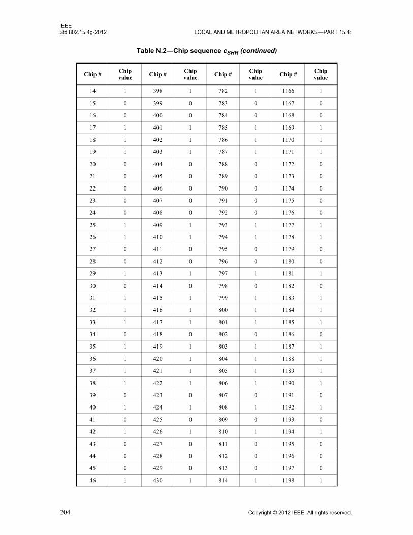
IEEEStd 802.15.4g-2012 LOCAL AND METROPOLITAN AREA NETWORKS—PART 15.4:
14 1 398 1 782 1 1166 1
15 0 399 0 783 0 1167 0
16 0 400 0 784 0 1168 0
17 1 401 1 785 1 1169 1
18 1 402 1 786 1 1170 1
19 1 403 1 787 1 1171 1
20 0 404 0 788 0 1172 0
21 0 405 0 789 0 1173 0
22 0 406 0 790 0 1174 0
23 0 407 0 791 0 1175 0
24 0 408 0 792 0 1176 0
25 1 409 1 793 1 1177 1
26 1 410 1 794 1 1178 1
27 0 411 0 795 0 1179 0
28 0 412 0 796 0 1180 0
29 1 413 1 797 1 1181 1
30 0 414 0 798 0 1182 0
31 1 415 1 799 1 1183 1
32 1 416 1 800 1 1184 1
33 1 417 1 801 1 1185 1
34 0 418 0 802 0 1186 0
35 1 419 1 803 1 1187 1
36 1 420 1 804 1 1188 1
37 1 421 1 805 1 1189 1
38 1 422 1 806 1 1190 1
39 0 423 0 807 0 1191 0
40 1 424 1 808 1 1192 1
41 0 425 0 809 0 1193 0
42 1 426 1 810 1 1194 1
43 0 427 0 811 0 1195 0
44 0 428 0 812 0 1196 0
45 0 429 0 813 0 1197 0
46 1 430 1 814 1 1198 1
Table N.2—Chip sequence cSHR (continued)
Chip # Chip value Chip # Chip
value Chip # Chip value Chip # Chip
value
204 Copyright © 2012 IEEE. All rights reserved.

IEEEWIRELESS MAC AND PHY SPECIFICATIONS FOR LR-WPANS—AMENDMENT 3 Std 802.15.4g-2012
47 0 431 0 815 0 1199 0
48 0 432 0 816 0 1200 0
49 1 433 1 817 1 1201 1
50 1 434 1 818 1 1202 1
51 1 435 1 819 1 1203 1
52 0 436 0 820 0 1204 0
53 0 437 0 821 0 1205 0
54 0 438 0 822 0 1206 0
55 0 439 0 823 0 1207 0
56 0 440 0 824 0 1208 0
57 1 441 1 825 1 1209 1
58 1 442 1 826 1 1210 1
59 0 443 0 827 0 1211 0
60 0 444 0 828 0 1212 0
61 1 445 1 829 1 1213 1
62 0 446 0 830 0 1214 0
63 1 447 1 831 1 1215 1
64 1 448 1 832 1 1216 0
65 1 449 1 833 1 1217 0
66 0 450 0 834 0 1218 1
67 1 451 1 835 1 1219 0
68 1 452 1 836 1 1220 0
69 1 453 1 837 1 1221 0
70 1 454 1 838 1 1222 0
71 0 455 0 839 0 1223 1
72 1 456 1 840 1 1224 0
73 0 457 0 841 0 1225 1
74 1 458 1 842 1 1226 0
75 0 459 0 843 0 1227 1
76 0 460 0 844 0 1228 1
77 0 461 0 845 0 1229 1
78 1 462 1 846 1 1230 0
79 0 463 0 847 0 1231 1
Table N.2—Chip sequence cSHR (continued)
Chip # Chip value Chip # Chip
value Chip # Chip value Chip # Chip
value
Copyright © 2012 IEEE. All rights reserved. 205

IEEEStd 802.15.4g-2012 LOCAL AND METROPOLITAN AREA NETWORKS—PART 15.4:
80 0 464 0 848 0 1232 1
81 1 465 1 849 1 1233 0
82 1 466 1 850 1 1234 0
83 1 467 1 851 1 1235 0
84 0 468 0 852 0 1236 1
85 0 469 0 853 0 1237 1
86 0 470 0 854 0 1238 1
87 0 471 0 855 0 1239 1
88 0 472 0 856 0 1240 1
89 1 473 1 857 1 1241 0
90 1 474 1 858 1 1242 0
91 0 475 0 859 0 1243 1
92 0 476 0 860 0 1244 1
93 1 477 1 861 1 1245 0
94 0 478 0 862 0 1246 1
95 1 479 1 863 1 1247 0
96 1 480 1 864 1 1248 1
97 1 481 1 865 1 1249 1
98 0 482 0 866 0 1250 0
99 1 483 1 867 1 1251 1
100 1 484 1 868 1 1252 1
101 1 485 1 869 1 1253 1
102 1 486 1 870 1 1254 1
103 0 487 0 871 0 1255 0
104 1 488 1 872 1 1256 1
105 0 489 0 873 0 1257 0
106 1 490 1 874 1 1258 1
107 0 491 0 875 0 1259 0
108 0 492 0 876 0 1260 0
109 0 493 0 877 0 1261 0
110 1 494 1 878 1 1262 1
111 0 495 0 879 0 1263 0
112 0 496 0 880 0 1264 0
Table N.2—Chip sequence cSHR (continued)
Chip # Chip value Chip # Chip
value Chip # Chip value Chip # Chip
value
206 Copyright © 2012 IEEE. All rights reserved.

IEEEWIRELESS MAC AND PHY SPECIFICATIONS FOR LR-WPANS—AMENDMENT 3 Std 802.15.4g-2012
113 1 497 1 881 1 1265 1
114 1 498 1 882 1 1266 1
115 1 499 1 883 1 1267 1
116 0 500 0 884 0 1268 0
117 0 501 0 885 0 1269 0
118 0 502 0 886 0 1270 0
119 0 503 0 887 0 1271 0
120 0 504 0 888 0 1272 0
121 1 505 1 889 1 1273 1
122 1 506 1 890 1 1274 1
123 0 507 0 891 0 1275 0
124 0 508 0 892 0 1276 0
125 1 509 1 893 1 1277 1
126 0 510 0 894 0 1278 0
127 1 511 1 895 1 1279 1
128 1 512 1 896 1 1280 1
129 1 513 1 897 1 1281 1
130 0 514 0 898 0 1282 0
131 1 515 1 899 1 1283 1
132 1 516 1 900 1 1284 1
133 1 517 1 901 1 1285 1
134 1 518 1 902 1 1286 1
135 0 519 0 903 0 1287 0
136 1 520 1 904 1 1288 1
137 0 521 0 905 0 1289 0
138 1 522 1 906 1 1290 1
139 0 523 0 907 0 1291 0
140 0 524 0 908 0 1292 0
141 0 525 0 909 0 1293 0
142 1 526 1 910 1 1294 1
143 0 527 0 911 0 1295 0
144 0 528 0 912 0 1296 0
145 1 529 1 913 1 1297 1
Table N.2—Chip sequence cSHR (continued)
Chip # Chip value Chip # Chip
value Chip # Chip value Chip # Chip
value
Copyright © 2012 IEEE. All rights reserved. 207
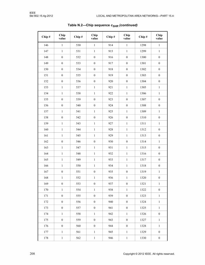
IEEEStd 802.15.4g-2012 LOCAL AND METROPOLITAN AREA NETWORKS—PART 15.4:
146 1 530 1 914 1 1298 1
147 1 531 1 915 1 1299 1
148 0 532 0 916 0 1300 0
149 0 533 0 917 0 1301 0
150 0 534 0 918 0 1302 0
151 0 535 0 919 0 1303 0
152 0 536 0 920 0 1304 0
153 1 537 1 921 1 1305 1
154 1 538 1 922 1 1306 1
155 0 539 0 923 0 1307 0
156 0 540 0 924 0 1308 0
157 1 541 1 925 1 1309 1
158 0 542 0 926 0 1310 0
159 1 543 1 927 1 1311 1
160 1 544 1 928 1 1312 0
161 1 545 1 929 1 1313 0
162 0 546 0 930 0 1314 1
163 1 547 1 931 1 1315 0
164 1 548 1 932 1 1316 0
165 1 549 1 933 1 1317 0
166 1 550 1 934 1 1318 0
167 0 551 0 935 0 1319 1
168 1 552 1 936 1 1320 0
169 0 553 0 937 0 1321 1
170 1 554 1 938 1 1322 0
171 0 555 0 939 0 1323 1
172 0 556 0 940 0 1324 1
173 0 557 0 941 0 1325 1
174 1 558 1 942 1 1326 0
175 0 559 0 943 0 1327 1
176 0 560 0 944 0 1328 1
177 1 561 1 945 1 1329 0
178 1 562 1 946 1 1330 0
Table N.2—Chip sequence cSHR (continued)
Chip # Chip value Chip # Chip
value Chip # Chip value Chip # Chip
value
208 Copyright © 2012 IEEE. All rights reserved.

IEEEWIRELESS MAC AND PHY SPECIFICATIONS FOR LR-WPANS—AMENDMENT 3 Std 802.15.4g-2012
179 1 563 1 947 1 1331 0
180 0 564 0 948 0 1332 1
181 0 565 0 949 0 1333 1
182 0 566 0 950 0 1334 1
183 0 567 0 951 0 1335 1
184 0 568 0 952 0 1336 1
185 1 569 1 953 1 1337 0
186 1 570 1 954 1 1338 0
187 0 571 0 955 0 1339 1
188 0 572 0 956 0 1340 1
189 1 573 1 957 1 1341 0
190 0 574 0 958 0 1342 1
191 1 575 1 959 1 1343 0
192 1 576 1 960 1 1344 1
193 1 577 1 961 1 1345 1
194 0 578 0 962 0 1346 0
195 1 579 1 963 1 1347 1
196 1 580 1 964 1 1348 1
197 1 581 1 965 1 1349 1
198 1 582 1 966 1 1350 1
199 0 583 0 967 0 1351 0
200 1 584 1 968 1 1352 1
201 0 585 0 969 0 1353 0
202 1 586 1 970 1 1354 1
203 0 587 0 971 0 1355 0
204 0 588 0 972 0 1356 0
205 0 589 0 973 0 1357 0
206 1 590 1 974 1 1358 1
207 0 591 0 975 0 1359 0
208 0 592 0 976 0 1360 0
209 1 593 1 977 1 1361 1
210 1 594 1 978 1 1362 1
211 1 595 1 979 1 1363 1
Table N.2—Chip sequence cSHR (continued)
Chip # Chip value Chip # Chip
value Chip # Chip value Chip # Chip
value
Copyright © 2012 IEEE. All rights reserved. 209
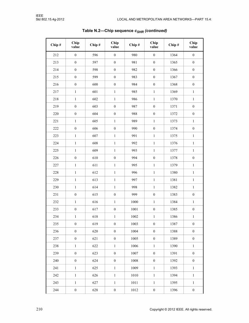
IEEEStd 802.15.4g-2012 LOCAL AND METROPOLITAN AREA NETWORKS—PART 15.4:
212 0 596 0 980 0 1364 0
213 0 597 0 981 0 1365 0
214 0 598 0 982 0 1366 0
215 0 599 0 983 0 1367 0
216 0 600 0 984 0 1368 0
217 1 601 1 985 1 1369 1
218 1 602 1 986 1 1370 1
219 0 603 0 987 0 1371 0
220 0 604 0 988 0 1372 0
221 1 605 1 989 1 1373 1
222 0 606 0 990 0 1374 0
223 1 607 1 991 1 1375 1
224 1 608 1 992 1 1376 1
225 1 609 1 993 1 1377 1
226 0 610 0 994 0 1378 0
227 1 611 1 995 1 1379 1
228 1 612 1 996 1 1380 1
229 1 613 1 997 1 1381 1
230 1 614 1 998 1 1382 1
231 0 615 0 999 0 1383 0
232 1 616 1 1000 1 1384 1
233 0 617 0 1001 0 1385 0
234 1 618 1 1002 1 1386 1
235 0 619 0 1003 0 1387 0
236 0 620 0 1004 0 1388 0
237 0 621 0 1005 0 1389 0
238 1 622 1 1006 1 1390 1
239 0 623 0 1007 0 1391 0
240 0 624 0 1008 0 1392 0
241 1 625 1 1009 1 1393 1
242 1 626 1 1010 1 1394 1
243 1 627 1 1011 1 1395 1
244 0 628 0 1012 0 1396 0
Table N.2—Chip sequence cSHR (continued)
Chip # Chip value Chip # Chip
value Chip # Chip value Chip # Chip
value
210 Copyright © 2012 IEEE. All rights reserved.

IEEEWIRELESS MAC AND PHY SPECIFICATIONS FOR LR-WPANS—AMENDMENT 3 Std 802.15.4g-2012
245 0 629 0 1013 0 1397 0
246 0 630 0 1014 0 1398 0
247 0 631 0 1015 0 1399 0
248 0 632 0 1016 0 1400 0
249 1 633 1 1017 1 1401 1
250 1 634 1 1018 1 1402 1
251 0 635 0 1019 0 1403 0
252 0 636 0 1020 0 1404 0
253 1 637 1 1021 1 1405 1
254 0 638 0 1022 0 1406 0
255 1 639 1 1023 1 1407 1
256 1 640 1 1024 0 1408 1
257 1 641 1 1025 0 1409 1
258 0 642 0 1026 1 1410 0
259 1 643 1 1027 0 1411 1
260 1 644 1 1028 0 1412 1
261 1 645 1 1029 0 1413 1
262 1 646 1 1030 0 1414 1
263 0 647 0 1031 1 1415 0
264 1 648 1 1032 0 1416 1
265 0 649 0 1033 1 1417 0
266 1 650 1 1034 0 1418 1
267 0 651 0 1035 1 1419 0
268 0 652 0 1036 1 1420 0
269 0 653 0 1037 1 1421 0
270 1 654 1 1038 0 1422 1
271 0 655 0 1039 1 1423 0
272 0 656 0 1040 1 1424 0
273 1 657 1 1041 0 1425 1
274 1 658 1 1042 0 1426 1
275 1 659 1 1043 0 1427 1
276 0 660 0 1044 1 1428 0
277 0 661 0 1045 1 1429 0
Table N.2—Chip sequence cSHR (continued)
Chip # Chip value Chip # Chip
value Chip # Chip value Chip # Chip
value
Copyright © 2012 IEEE. All rights reserved. 211
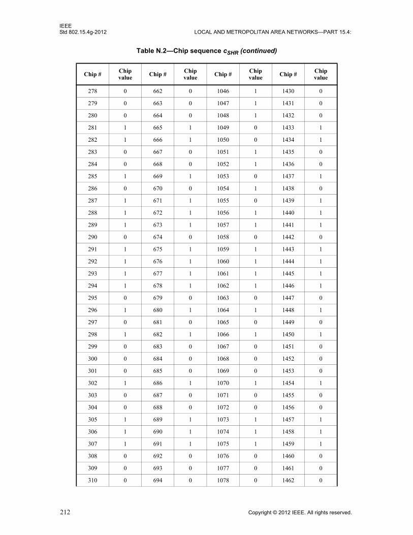
IEEEStd 802.15.4g-2012 LOCAL AND METROPOLITAN AREA NETWORKS—PART 15.4:
278 0 662 0 1046 1 1430 0
279 0 663 0 1047 1 1431 0
280 0 664 0 1048 1 1432 0
281 1 665 1 1049 0 1433 1
282 1 666 1 1050 0 1434 1
283 0 667 0 1051 1 1435 0
284 0 668 0 1052 1 1436 0
285 1 669 1 1053 0 1437 1
286 0 670 0 1054 1 1438 0
287 1 671 1 1055 0 1439 1
288 1 672 1 1056 1 1440 1
289 1 673 1 1057 1 1441 1
290 0 674 0 1058 0 1442 0
291 1 675 1 1059 1 1443 1
292 1 676 1 1060 1 1444 1
293 1 677 1 1061 1 1445 1
294 1 678 1 1062 1 1446 1
295 0 679 0 1063 0 1447 0
296 1 680 1 1064 1 1448 1
297 0 681 0 1065 0 1449 0
298 1 682 1 1066 1 1450 1
299 0 683 0 1067 0 1451 0
300 0 684 0 1068 0 1452 0
301 0 685 0 1069 0 1453 0
302 1 686 1 1070 1 1454 1
303 0 687 0 1071 0 1455 0
304 0 688 0 1072 0 1456 0
305 1 689 1 1073 1 1457 1
306 1 690 1 1074 1 1458 1
307 1 691 1 1075 1 1459 1
308 0 692 0 1076 0 1460 0
309 0 693 0 1077 0 1461 0
310 0 694 0 1078 0 1462 0
Table N.2—Chip sequence cSHR (continued)
Chip # Chip value Chip # Chip
value Chip # Chip value Chip # Chip
value
212 Copyright © 2012 IEEE. All rights reserved.

IEEEWIRELESS MAC AND PHY SPECIFICATIONS FOR LR-WPANS—AMENDMENT 3 Std 802.15.4g-2012
311 0 695 0 1079 0 1463 0
312 0 696 0 1080 0 1464 0
313 1 697 1 1081 1 1465 1
314 1 698 1 1082 1 1466 1
315 0 699 0 1083 0 1467 0
316 0 700 0 1084 0 1468 0
317 1 701 1 1085 1 1469 1
318 0 702 0 1086 0 1470 0
319 1 703 1 1087 1 1471 1
320 1 704 1 1088 0 1472 0
321 1 705 1 1089 0 1473 0
322 0 706 0 1090 1 1474 1
323 1 707 1 1091 0 1475 0
324 1 708 1 1092 0 1476 0
325 1 709 1 1093 0 1477 0
326 1 710 1 1094 0 1478 0
327 0 711 0 1095 1 1479 1
328 1 712 1 1096 0 1480 0
329 0 713 0 1097 1 1481 1
330 1 714 1 1098 0 1482 0
331 0 715 0 1099 1 1483 1
332 0 716 0 1100 1 1484 1
333 0 717 0 1101 1 1485 1
334 1 718 1 1102 0 1486 0
335 0 719 0 1103 1 1487 1
336 0 720 0 1104 1 1488 1
337 1 721 1 1105 0 1489 0
338 1 722 1 1106 0 1490 0
339 1 723 1 1107 0 1491 0
340 0 724 0 1108 1 1492 1
341 0 725 0 1109 1 1493 1
342 0 726 0 1110 1 1494 1
343 0 727 0 1111 1 1495 1
Table N.2—Chip sequence cSHR (continued)
Chip # Chip value Chip # Chip
value Chip # Chip value Chip # Chip
value
Copyright © 2012 IEEE. All rights reserved. 213
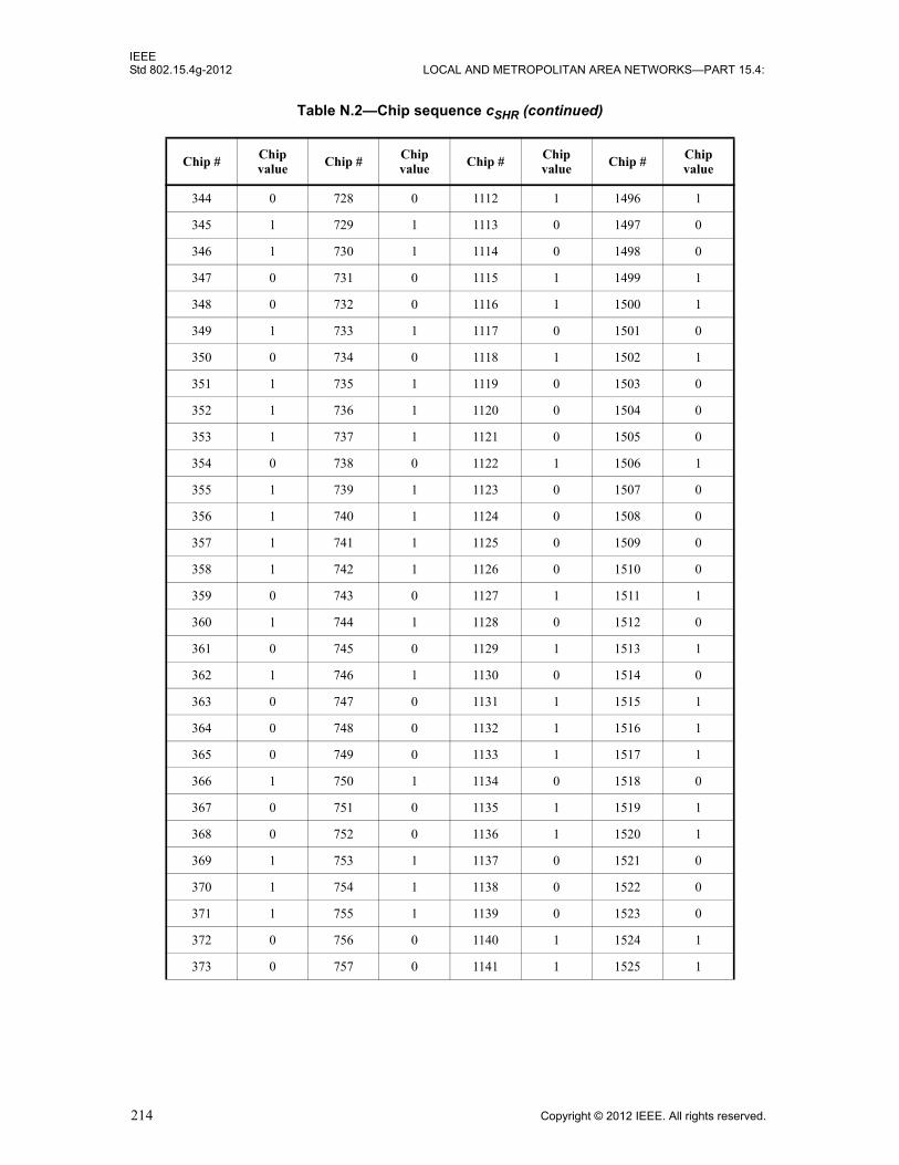
IEEEStd 802.15.4g-2012 LOCAL AND METROPOLITAN AREA NETWORKS—PART 15.4:
344 0 728 0 1112 1 1496 1
345 1 729 1 1113 0 1497 0
346 1 730 1 1114 0 1498 0
347 0 731 0 1115 1 1499 1
348 0 732 0 1116 1 1500 1
349 1 733 1 1117 0 1501 0
350 0 734 0 1118 1 1502 1
351 1 735 1 1119 0 1503 0
352 1 736 1 1120 0 1504 0
353 1 737 1 1121 0 1505 0
354 0 738 0 1122 1 1506 1
355 1 739 1 1123 0 1507 0
356 1 740 1 1124 0 1508 0
357 1 741 1 1125 0 1509 0
358 1 742 1 1126 0 1510 0
359 0 743 0 1127 1 1511 1
360 1 744 1 1128 0 1512 0
361 0 745 0 1129 1 1513 1
362 1 746 1 1130 0 1514 0
363 0 747 0 1131 1 1515 1
364 0 748 0 1132 1 1516 1
365 0 749 0 1133 1 1517 1
366 1 750 1 1134 0 1518 0
367 0 751 0 1135 1 1519 1
368 0 752 0 1136 1 1520 1
369 1 753 1 1137 0 1521 0
370 1 754 1 1138 0 1522 0
371 1 755 1 1139 0 1523 0
372 0 756 0 1140 1 1524 1
373 0 757 0 1141 1 1525 1
Table N.2—Chip sequence cSHR (continued)
Chip # Chip value Chip # Chip
value Chip # Chip value Chip # Chip
value
214 Copyright © 2012 IEEE. All rights reserved.

IEEEWIRELESS MAC AND PHY SPECIFICATIONS FOR LR-WPANS—AMENDMENT 3 Std 802.15.4g-2012
N.4 Generation of the PHR
The Spreading Mode (SM) field is set to zero (DSSS applied to the PSDU), the Rate Mode field (R1, R0) is set to (0,0) corresponding to RateMode zero, the Reserved field entries are set to (0,0), and the Length field entries are set to the binary representation of “7,” corresponding to the PSDU length of the frame. The complete PHR field including the HCS field (H7–H0) is shown in Table N.3.
After padding the 24 information bits by 6 additional zero termination bits, the sequence of the 60 code-bits at the output of convolutional encoding is given as follows:
0000 0000 0000 0000 0000 0000 0011 1001 0100 0110 0011 1000 0000 0111 1011
The sequences after interleaving is given as
1000 0010 1100 0011 0010 0100 1000 0011 0000 1110 0001 0000 0010 0000 0000
After BDE, the code-bit sequence changes to
0000 0011 0111 1101 1100 0111 0000 0010 0000 1011 1110 0000 0011 1111 1111
Note that for bit-differential encoding of the PHR code-bits, the first reference value is the last sample of , which is equal to one, as described in Equation (L.1).
374 0 758 0 1142 1 1526 1
375 0 759 0 1143 1 1527 1
376 0 760 0 1144 1 1528 1
377 1 761 1 1145 0 1529 0
378 1 762 1 1146 0 1530 0
379 0 763 0 1147 1 1531 1
380 0 764 0 1148 1 1532 1
381 1 765 1 1149 0 1533 0
382 0 766 0 1150 1 1534 1
383 1 767 1 1151 0 1535 0
Table N.3—PHR for MR-O-QPSK
Bit # 0 1 2 3 4 5–15 16–23
Bit mapping SM RM1 RM0 R1 R0 L10–L0 H7–H0
value 0 0 0 0 0 0 0 0 0 0 0 0 0 1 1 1 00010101
Table N.2—Chip sequence cSHR (continued)
Chip # Chip value Chip # Chip
value Chip # Chip value Chip # Chip
value
10 6×
bSHRBDE
Copyright © 2012 IEEE. All rights reserved. 215
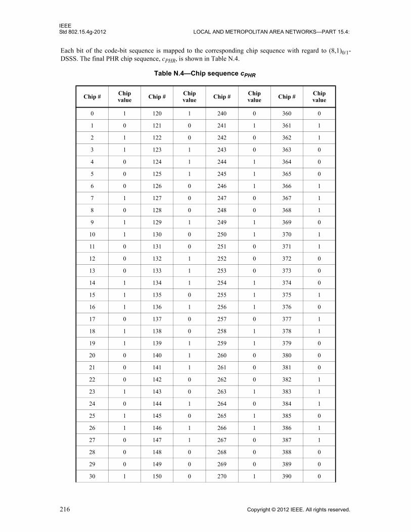
IEEEStd 802.15.4g-2012 LOCAL AND METROPOLITAN AREA NETWORKS—PART 15.4:
Each bit of the code-bit sequence is mapped to the corresponding chip sequence with regard to (8,1)0/1-DSSS. The final PHR chip sequence, cPHR, is shown in Table N.4.
Table N.4—Chip sequence cPHR
Chip #Chip value Chip #
Chip value Chip #
Chip value Chip #
Chip value
0 1 120 1 240 0 360 0
1 0 121 0 241 1 361 1
2 1 122 0 242 0 362 1
3 1 123 1 243 0 363 0
4 0 124 1 244 1 364 0
5 0 125 1 245 1 365 0
6 0 126 0 246 1 366 1
7 1 127 0 247 0 367 1
8 0 128 0 248 0 368 1
9 1 129 1 249 1 369 0
10 1 130 0 250 1 370 1
11 0 131 0 251 0 371 1
12 0 132 1 252 0 372 0
13 0 133 1 253 0 373 0
14 1 134 1 254 1 374 0
15 1 135 0 255 1 375 1
16 1 136 1 256 1 376 0
17 0 137 0 257 0 377 1
18 1 138 0 258 1 378 1
19 1 139 1 259 1 379 0
20 0 140 1 260 0 380 0
21 0 141 1 261 0 381 0
22 0 142 0 262 0 382 1
23 1 143 0 263 1 383 1
24 0 144 1 264 0 384 1
25 1 145 0 265 1 385 0
26 1 146 1 266 1 386 1
27 0 147 1 267 0 387 1
28 0 148 0 268 0 388 0
29 0 149 0 269 0 389 0
30 1 150 0 270 1 390 0
216 Copyright © 2012 IEEE. All rights reserved.

IEEEWIRELESS MAC AND PHY SPECIFICATIONS FOR LR-WPANS—AMENDMENT 3 Std 802.15.4g-2012
31 1 151 1 271 1 391 1
32 1 152 0 272 1 392 0
33 0 153 1 273 0 393 1
34 1 154 1 274 1 394 1
35 1 155 0 275 1 395 0
36 0 156 0 276 0 396 0
37 0 157 0 277 0 397 0
38 0 158 1 278 0 398 1
39 1 159 1 279 1 399 1
40 0 160 1 280 0 400 0
41 1 161 0 281 1 401 1
42 1 162 1 282 1 402 0
43 0 163 1 283 0 403 0
44 0 164 0 284 0 404 1
45 0 165 0 285 0 405 1
46 1 166 0 286 1 406 1
47 1 167 1 287 1 407 0
48 0 168 1 288 0 408 1
49 1 169 0 289 1 409 0
50 0 170 0 290 0 410 0
51 0 171 1 291 0 411 1
52 1 172 1 292 1 412 1
53 1 173 1 293 1 413 1
54 1 174 0 294 1 414 0
55 0 175 0 295 0 415 0
56 1 176 0 296 0 416 0
57 0 177 1 297 1 417 1
58 0 178 0 298 1 418 0
59 1 179 0 299 0 419 0
60 1 180 1 300 0 420 1
61 1 181 1 301 0 421 1
62 0 182 1 302 1 422 1
63 0 183 0 303 1 423 0
Table N.4—Chip sequence cPHR (continued)
Chip # Chip value Chip # Chip
value Chip # Chip value Chip # Chip
value
Copyright © 2012 IEEE. All rights reserved. 217

IEEEStd 802.15.4g-2012 LOCAL AND METROPOLITAN AREA NETWORKS—PART 15.4:
64 1 184 1 304 0 424 1
65 0 185 0 305 1 425 0
66 1 186 0 306 0 426 0
67 1 187 1 307 0 427 1
68 0 188 1 308 1 428 1
69 0 189 1 309 1 429 1
70 0 190 0 310 1 430 0
71 1 191 0 311 0 431 0
72 1 192 1 312 1 432 0
73 0 193 0 313 0 433 1
74 0 194 1 314 0 434 0
75 1 195 1 315 1 435 0
76 1 196 0 316 1 436 1
77 1 197 0 317 1 437 1
78 0 198 0 318 0 438 1
79 0 199 1 319 0 439 0
80 0 200 0 320 0 440 1
81 1 201 1 321 1 441 0
82 0 202 1 322 0 442 0
83 0 203 0 323 0 443 1
84 1 204 0 324 1 444 1
85 1 205 0 325 1 445 1
86 1 206 1 326 1 446 0
87 0 207 1 327 0 447 0
88 1 208 1 328 1 448 0
89 0 209 0 329 0 449 1
90 0 210 1 330 0 450 0
91 1 211 1 331 1 451 0
92 1 212 0 332 1 452 1
93 1 213 0 333 1 453 1
94 0 214 0 334 0 454 1
95 0 215 1 335 0 455 0
96 0 216 0 336 0 456 1
Table N.4—Chip sequence cPHR (continued)
Chip # Chip value Chip # Chip
value Chip # Chip value Chip # Chip
value
218 Copyright © 2012 IEEE. All rights reserved.

IEEEWIRELESS MAC AND PHY SPECIFICATIONS FOR LR-WPANS—AMENDMENT 3 Std 802.15.4g-2012
N.5 Generation of the PSDU
The bit sequence of the example PSDU is
bPSDU = 0100 0000 0000 0000 0101 0110 0101 1101 0010 1001 1111 1010 0010 1000
Note that for each message octet given in Table N.1, the least significant bit is processed first in time.
Prior to convolutional encoding, this bit sequence needs to be extended by six, zero termination bits and one additional zero pad bit, such that the overall length is .
= 0100 0000 0000 0000 0101 0110 0101 1101 0010 1001 1111 1010 0010 1000 0000 000
97 1 217 1 337 1 457 0
98 0 218 1 338 0 458 0
99 0 219 0 339 0 459 1
100 1 220 0 340 1 460 1
101 1 221 0 341 1 461 1
102 1 222 1 342 1 462 0
103 0 223 1 343 0 463 0
104 1 224 1 344 0 464 0
105 0 225 0 345 1 465 1
106 0 226 1 346 1 466 0
107 1 227 1 347 0 467 0
108 1 228 0 348 0 468 1
109 1 229 0 349 0 469 1
110 0 230 0 350 1 470 1
111 0 231 1 351 1 471 0
112 1 232 0 352 1 472 1
113 0 233 1 353 0 473 0
114 1 234 1 354 1 474 0
115 1 235 0 355 1 475 1
116 0 236 0 356 0 476 1
117 0 237 0 357 0 477 1
118 0 238 1 358 0 478 0
119 1 239 1 359 1 479 0
Table N.4—Chip sequence cPHR (continued)
Chip # Chip value Chip # Chip
value Chip # Chip value Chip # Chip
value
NINTRLV 2⁄ 63=
bPSDUext
Copyright © 2012 IEEE. All rights reserved. 219
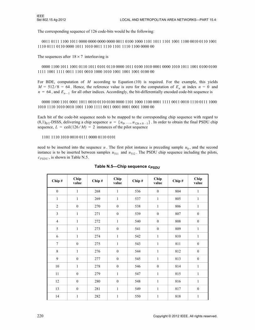
IEEEStd 802.15.4g-2012 LOCAL AND METROPOLITAN AREA NETWORKS—PART 15.4:
The corresponding sequence of 126 code-bits would be the following:
0011 0111 1100 1011 0000 0000 0000 0000 0011 0100 1000 1101 1011 1101 1001 1100 0010 0110 1001 1110 0111 0110 0000 1011 1010 0011 1110 1101 1110 1100 0000 00
The sequences after interleaving is
0000 1100 1011 1001 0110 1011 0101 0110 0000 1011 0100 1010 0001 0000 1010 1011 1001 0100 0100 1111 1001 1111 0011 1101 0010 1000 1010 1001 1001 1001 0100 00
For BDE, computation of according to Equation (10) is required. For the example, this yields . Hence, the reference value is zero for the computation of at index and
, and for all other indices. Accordingly, the bit-differentially encoded code-bit sequence is
0000 1000 1101 0001 1011 0010 0110 0100 0000 1101 1000 1100 0001 1111 0011 0010 1110 0111 1000 1010 1110 1010 0010 1001 1100 1111 0011 0001 0001 0001 1000 00
Each bit of the code-bit sequence needs to be mapped to the corresponding chip sequence with regard to (8,1)0/1-DSSS, delivering a chip sequence . In order to obtain the final PSDU chip sequence, instances of the pilot sequence
1101 1110 1010 0010 0111 0000 0110 0101
need to be inserted into the sequence . The first pilot instance is preceding sample , and the second instance is to be inserted between samples and . The PSDU chip sequence including the pilots,
, is shown in Table N.5.
Table N.5—Chip sequence cPSDU
Chip # Chip value
Chip # Chip value
Chip # Chip value
Chip # Chip value
0 1 268 1 536 0 804 1
1 1 269 1 537 1 805 1
2 0 270 0 538 1 806 1
3 1 271 0 539 0 807 0
4 1 272 1 540 0 808 0
5 1 273 0 541 0 809 1
6 1 274 1 542 1 810 1
7 0 275 1 543 1 811 0
8 1 276 0 544 1 812 0
9 0 277 0 545 1 813 0
10 1 278 0 546 0 814 1
11 0 279 1 547 1 815 1
12 0 280 0 548 1 816 1
13 0 281 1 549 1 817 0
14 1 282 1 550 1 818 1
18 7×
MM 512 8⁄ 64= = En n 0=n 64= En 1–
u u0 … u126 8 1–×, ,{ }=L ceil 126 M⁄( ) 2= =
u u0u511 u512
cPSDU
220 Copyright © 2012 IEEE. All rights reserved.
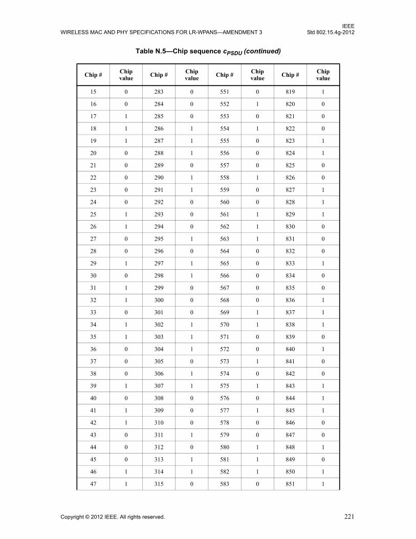
IEEEWIRELESS MAC AND PHY SPECIFICATIONS FOR LR-WPANS—AMENDMENT 3 Std 802.15.4g-2012
15 0 283 0 551 0 819 1
16 0 284 0 552 1 820 0
17 1 285 0 553 0 821 0
18 1 286 1 554 1 822 0
19 1 287 1 555 0 823 1
20 0 288 1 556 0 824 1
21 0 289 0 557 0 825 0
22 0 290 1 558 1 826 0
23 0 291 1 559 0 827 1
24 0 292 0 560 0 828 1
25 1 293 0 561 1 829 1
26 1 294 0 562 1 830 0
27 0 295 1 563 1 831 0
28 0 296 0 564 0 832 0
29 1 297 1 565 0 833 1
30 0 298 1 566 0 834 0
31 1 299 0 567 0 835 0
32 1 300 0 568 0 836 1
33 0 301 0 569 1 837 1
34 1 302 1 570 1 838 1
35 1 303 1 571 0 839 0
36 0 304 1 572 0 840 1
37 0 305 0 573 1 841 0
38 0 306 1 574 0 842 0
39 1 307 1 575 1 843 1
40 0 308 0 576 0 844 1
41 1 309 0 577 1 845 1
42 1 310 0 578 0 846 0
43 0 311 1 579 0 847 0
44 0 312 0 580 1 848 1
45 0 313 1 581 1 849 0
46 1 314 1 582 1 850 1
47 1 315 0 583 0 851 1
Table N.5—Chip sequence cPSDU (continued)
Chip # Chip value Chip # Chip
value Chip # Chip value Chip # Chip
value
Copyright © 2012 IEEE. All rights reserved. 221

IEEEStd 802.15.4g-2012 LOCAL AND METROPOLITAN AREA NETWORKS—PART 15.4:
48 1 316 0 584 1 852 0
49 0 317 0 585 0 853 0
50 1 318 1 586 0 854 0
51 1 319 1 587 1 855 1
52 0 320 0 588 1 856 0
53 0 321 1 589 1 857 1
54 0 322 0 590 0 858 1
55 1 323 0 591 0 859 0
56 0 324 1 592 0 860 0
57 1 325 1 593 1 861 0
58 1 326 1 594 0 862 1
59 0 327 0 595 0 863 1
60 0 328 1 596 1 864 0
61 0 329 0 597 1 865 1
62 1 330 0 598 1 866 0
63 1 331 1 599 0 867 0
64 0 332 1 600 0 868 1
65 1 333 1 601 1 869 1
66 0 334 0 602 1 870 1
67 0 335 0 603 0 871 0
68 1 336 1 604 0 872 1
69 1 337 0 605 0 873 0
70 1 338 1 606 1 874 0
71 0 339 1 607 1 875 1
72 0 340 0 608 1 876 1
73 1 341 0 609 0 877 1
74 1 342 0 610 1 878 0
75 0 343 1 611 1 879 0
76 0 344 1 612 0 880 0
77 0 345 0 613 0 881 1
78 1 346 0 614 0 882 0
79 1 347 1 615 1 883 0
80 1 348 1 616 1 884 1
Table N.5—Chip sequence cPSDU (continued)
Chip # Chip value Chip # Chip
value Chip # Chip value Chip # Chip
value
222 Copyright © 2012 IEEE. All rights reserved.
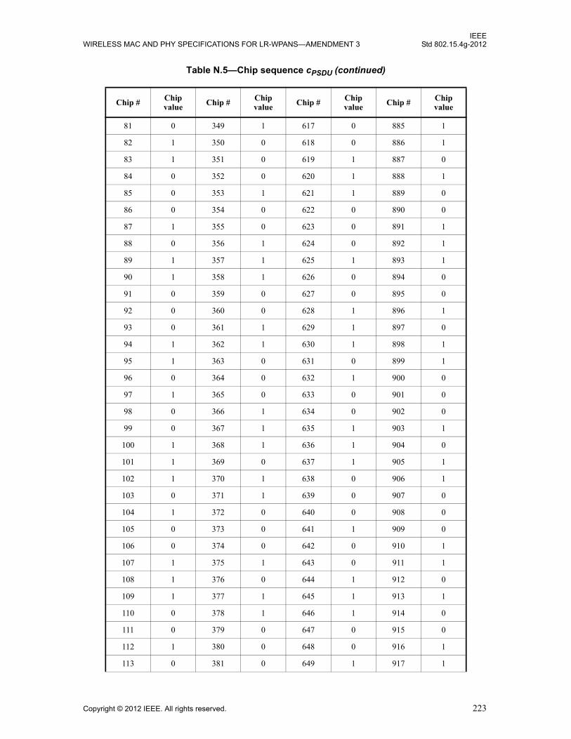
IEEEWIRELESS MAC AND PHY SPECIFICATIONS FOR LR-WPANS—AMENDMENT 3 Std 802.15.4g-2012
81 0 349 1 617 0 885 1
82 1 350 0 618 0 886 1
83 1 351 0 619 1 887 0
84 0 352 0 620 1 888 1
85 0 353 1 621 1 889 0
86 0 354 0 622 0 890 0
87 1 355 0 623 0 891 1
88 0 356 1 624 0 892 1
89 1 357 1 625 1 893 1
90 1 358 1 626 0 894 0
91 0 359 0 627 0 895 0
92 0 360 0 628 1 896 1
93 0 361 1 629 1 897 0
94 1 362 1 630 1 898 1
95 1 363 0 631 0 899 1
96 0 364 0 632 1 900 0
97 1 365 0 633 0 901 0
98 0 366 1 634 0 902 0
99 0 367 1 635 1 903 1
100 1 368 1 636 1 904 0
101 1 369 0 637 1 905 1
102 1 370 1 638 0 906 1
103 0 371 1 639 0 907 0
104 1 372 0 640 0 908 0
105 0 373 0 641 1 909 0
106 0 374 0 642 0 910 1
107 1 375 1 643 0 911 1
108 1 376 0 644 1 912 0
109 1 377 1 645 1 913 1
110 0 378 1 646 1 914 0
111 0 379 0 647 0 915 0
112 1 380 0 648 0 916 1
113 0 381 0 649 1 917 1
Table N.5—Chip sequence cPSDU (continued)
Chip # Chip value Chip # Chip
value Chip # Chip value Chip # Chip
value
Copyright © 2012 IEEE. All rights reserved. 223
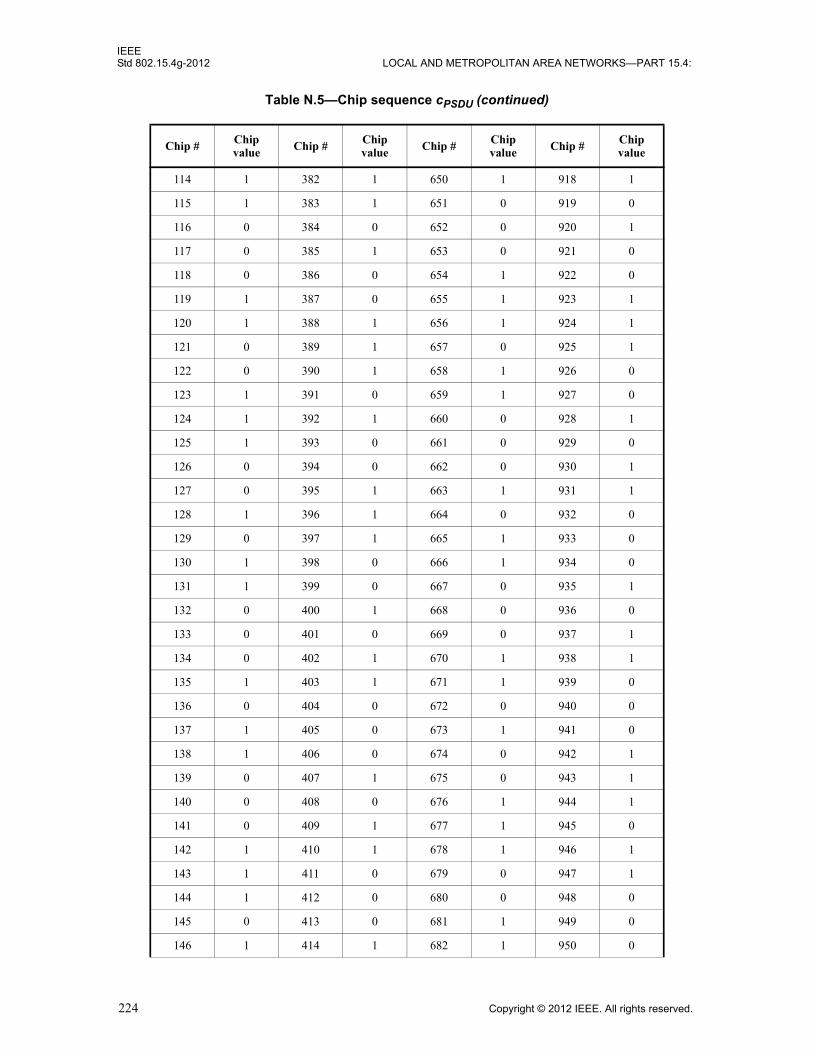
IEEEStd 802.15.4g-2012 LOCAL AND METROPOLITAN AREA NETWORKS—PART 15.4:
114 1 382 1 650 1 918 1
115 1 383 1 651 0 919 0
116 0 384 0 652 0 920 1
117 0 385 1 653 0 921 0
118 0 386 0 654 1 922 0
119 1 387 0 655 1 923 1
120 1 388 1 656 1 924 1
121 0 389 1 657 0 925 1
122 0 390 1 658 1 926 0
123 1 391 0 659 1 927 0
124 1 392 1 660 0 928 1
125 1 393 0 661 0 929 0
126 0 394 0 662 0 930 1
127 0 395 1 663 1 931 1
128 1 396 1 664 0 932 0
129 0 397 1 665 1 933 0
130 1 398 0 666 1 934 0
131 1 399 0 667 0 935 1
132 0 400 1 668 0 936 0
133 0 401 0 669 0 937 1
134 0 402 1 670 1 938 1
135 1 403 1 671 1 939 0
136 0 404 0 672 0 940 0
137 1 405 0 673 1 941 0
138 1 406 0 674 0 942 1
139 0 407 1 675 0 943 1
140 0 408 0 676 1 944 1
141 0 409 1 677 1 945 0
142 1 410 1 678 1 946 1
143 1 411 0 679 0 947 1
144 1 412 0 680 0 948 0
145 0 413 0 681 1 949 0
146 1 414 1 682 1 950 0
Table N.5—Chip sequence cPSDU (continued)
Chip # Chip value Chip # Chip
value Chip # Chip value Chip # Chip
value
224 Copyright © 2012 IEEE. All rights reserved.
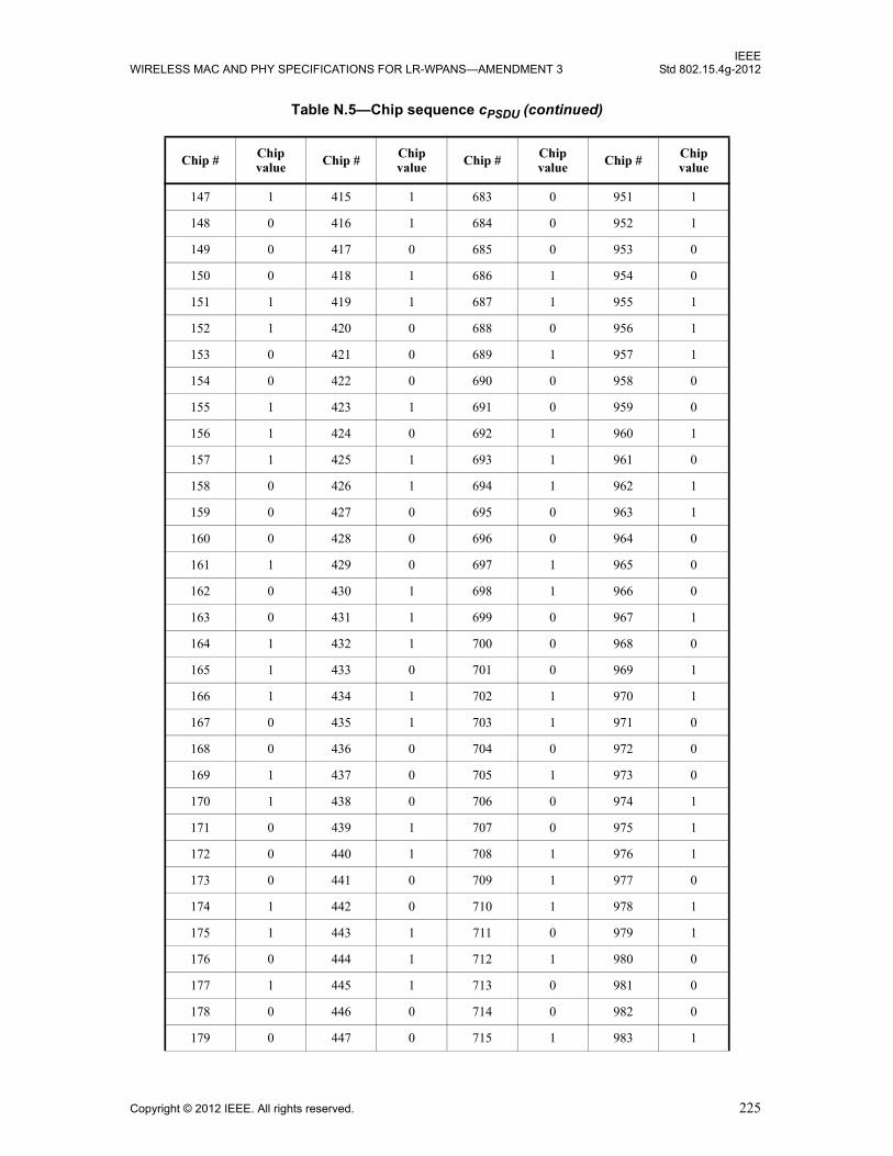
IEEEWIRELESS MAC AND PHY SPECIFICATIONS FOR LR-WPANS—AMENDMENT 3 Std 802.15.4g-2012
147 1 415 1 683 0 951 1
148 0 416 1 684 0 952 1
149 0 417 0 685 0 953 0
150 0 418 1 686 1 954 0
151 1 419 1 687 1 955 1
152 1 420 0 688 0 956 1
153 0 421 0 689 1 957 1
154 0 422 0 690 0 958 0
155 1 423 1 691 0 959 0
156 1 424 0 692 1 960 1
157 1 425 1 693 1 961 0
158 0 426 1 694 1 962 1
159 0 427 0 695 0 963 1
160 0 428 0 696 0 964 0
161 1 429 0 697 1 965 0
162 0 430 1 698 1 966 0
163 0 431 1 699 0 967 1
164 1 432 1 700 0 968 0
165 1 433 0 701 0 969 1
166 1 434 1 702 1 970 1
167 0 435 1 703 1 971 0
168 0 436 0 704 0 972 0
169 1 437 0 705 1 973 0
170 1 438 0 706 0 974 1
171 0 439 1 707 0 975 1
172 0 440 1 708 1 976 1
173 0 441 0 709 1 977 0
174 1 442 0 710 1 978 1
175 1 443 1 711 0 979 1
176 0 444 1 712 1 980 0
177 1 445 1 713 0 981 0
178 0 446 0 714 0 982 0
179 0 447 0 715 1 983 1
Table N.5—Chip sequence cPSDU (continued)
Chip # Chip value Chip # Chip
value Chip # Chip value Chip # Chip
value
Copyright © 2012 IEEE. All rights reserved. 225

IEEEStd 802.15.4g-2012 LOCAL AND METROPOLITAN AREA NETWORKS—PART 15.4:
180 1 448 0 716 1 984 1
181 1 449 1 717 1 985 0
182 1 450 0 718 0 986 0
183 0 451 0 719 0 987 1
184 1 452 1 720 0 988 1
185 0 453 1 721 1 989 1
186 0 454 1 722 0 990 0
187 1 455 0 723 0 991 0
188 1 456 1 724 1 992 1
189 1 457 0 725 1 993 0
190 0 458 0 726 1 994 1
191 0 459 1 727 0 995 1
192 1 460 1 728 0 996 0
193 0 461 1 729 1 997 0
194 1 462 0 730 1 998 0
195 1 463 0 731 0 999 1
196 0 464 0 732 0 1000 0
197 0 465 1 733 0 1001 1
198 0 466 0 734 1 1002 1
199 1 467 0 735 1 1003 0
200 0 468 1 736 0 1004 0
201 1 469 1 737 1 1005 0
202 1 470 1 738 0 1006 1
203 0 471 0 739 0 1007 1
204 0 472 1 740 1 1008 1
205 0 473 0 741 1 1009 0
206 1 474 0 742 1 1010 1
207 1 475 1 743 0 1011 1
208 0 476 1 744 0 1012 0
209 1 477 1 745 1 1013 0
210 0 478 0 746 1 1014 0
211 0 479 0 747 0 1015 1
212 1 480 1 748 0 1016 1
Table N.5—Chip sequence cPSDU (continued)
Chip # Chip value Chip # Chip
value Chip # Chip value Chip # Chip
value
226 Copyright © 2012 IEEE. All rights reserved.

IEEEWIRELESS MAC AND PHY SPECIFICATIONS FOR LR-WPANS—AMENDMENT 3 Std 802.15.4g-2012
213 1 481 0 749 0 1017 0
214 1 482 1 750 1 1018 0
215 0 483 1 751 1 1019 1
216 0 484 0 752 0 1020 1
217 1 485 0 753 1 1021 1
218 1 486 0 754 0 1022 0
219 0 487 1 755 0 1023 0
220 0 488 0 756 1 1024 0
221 0 489 1 757 1 1025 1
222 1 490 1 758 1 1026 0
223 1 491 0 759 0 1027 0
224 1 492 0 760 0 1028 1
225 0 493 0 761 1 1029 1
226 1 494 1 762 1 1030 1
227 1 495 1 763 0 1031 0
228 0 496 0 764 0 1032 0
229 0 497 1 765 0 1033 1
230 0 498 0 766 1 1034 1
231 1 499 0 767 1 1035 0
232 1 500 1 768 1 1036 0
233 0 501 1 769 0 1037 0
234 0 502 1 770 1 1038 1
235 1 503 0 771 1 1039 1
236 1 504 1 772 0 1040 1
237 1 505 0 773 0 1041 0
238 0 506 0 774 0 1042 1
239 0 507 1 775 1 1043 1
240 0 508 1 776 0 1044 0
241 1 509 1 777 1 1045 0
242 0 510 0 778 1 1046 0
243 0 511 0 779 0 1047 1
244 1 512 1 780 0 1048 0
245 1 513 0 781 0 1049 1
Table N.5—Chip sequence cPSDU (continued)
Chip # Chip value Chip # Chip
value Chip # Chip value Chip # Chip
value
Copyright © 2012 IEEE. All rights reserved. 227
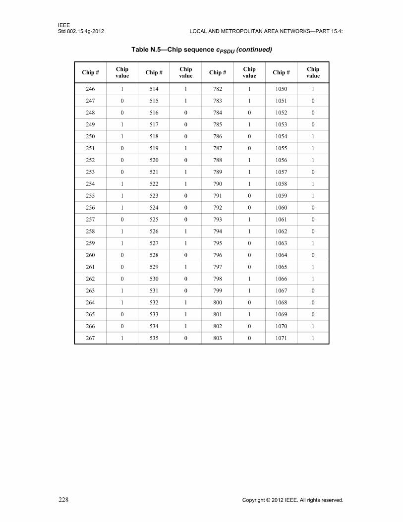
IEEEStd 802.15.4g-2012 LOCAL AND METROPOLITAN AREA NETWORKS—PART 15.4:
246 1 514 1 782 1 1050 1
247 0 515 1 783 1 1051 0
248 0 516 0 784 0 1052 0
249 1 517 0 785 1 1053 0
250 1 518 0 786 0 1054 1
251 0 519 1 787 0 1055 1
252 0 520 0 788 1 1056 1
253 0 521 1 789 1 1057 0
254 1 522 1 790 1 1058 1
255 1 523 0 791 0 1059 1
256 1 524 0 792 0 1060 0
257 0 525 0 793 1 1061 0
258 1 526 1 794 1 1062 0
259 1 527 1 795 0 1063 1
260 0 528 0 796 0 1064 0
261 0 529 1 797 0 1065 1
262 0 530 0 798 1 1066 1
263 1 531 0 799 1 1067 0
264 1 532 1 800 0 1068 0
265 0 533 1 801 1 1069 0
266 0 534 1 802 0 1070 1
267 1 535 0 803 0 1071 1
Table N.5—Chip sequence cPSDU (continued)
Chip # Chip value Chip # Chip
value Chip # Chip value Chip # Chip
value
228 Copyright © 2012 IEEE. All rights reserved.

IEEEWIRELESS MAC AND PHY SPECIFICATIONS FOR LR-WPANS—AMENDMENT 3 Std 802.15.4g-2012
Insert after new Annex N the following new annex (Annex O):
Annex O
(informative)
Example of encoding a packet for MR-FSK PHY
O.1 Introduction
This annex provides six examples of how the MR-FSK PHY would encode a sample PSDU received from the MAC sublayer. The list of examples with parameters is given in Table O.1. For additional examples, see“Examples of encoding a packet for the MR-FSK PHY– Part 1” [B22] and“Examples of encoding a packet for the MR-FSK PHY– Part 2” [B23]; the most recent versions of these documents should be referenced.
In all examples, the message encoded is a PSDU that is 7 octets in length. The message constitutes an acknowledgment frame with a 3-octet MHR and a 4-octet FCS, as defined in 5.2.1.9. The bit sequence of the example PSDU is: 0100 0000 0000 0000 0101 0110 0101 1101 0010 1001 1111 1010 0010 1000.
The encoding illustration goes through the following stages:
a) Generating the bit sequence of the SHR
b) Generating the bit sequence of the PHR
c) Concatenating the PHR, PSDU, and when FEC is enabled, tail bits and pad bits
d) Encoding of the concatenated bit sequence with the specified FEC code when FEC is enabled
e) Interleaving of the code-bit sequence when interleaving is enabled (requires FEC also enabled)
f) Data whitening of the PSDU when data whitening is enabled
g) Concatenation to form the PPDU
For each example, the settings of the PIB attributes are also shown.
Table O.1—Encoding examples for MR-FSK PHY
Example Modulation Data whitening
FEC Interleaving phyMRFSKSFD Subclause number
1 Filtered 2FSK Disabled Disabled Disabled 0 O.2
2 Filtered 2FSK Enabled Disabled Disabled 0 O.3
3 Filtered 2FSK Enabled RSC Enabled 0 O.4
4 Filtered 2FSK Disabled NRNSC Enabled 1 O.5
5 Filtered 4FSK Disabled Disabled Disabled 1 O.6
6 Filtered 4FSK Enabled RSC Enabled 0 O.7
Copyright © 2012 IEEE. All rights reserved. 229

IEEEStd 802.15.4g-2012 LOCAL AND METROPOLITAN AREA NETWORKS—PART 15.4:
O.2 Example 1
O.2.1 Settings
For this example, selected PIB attributes are set as follows:
— phyFSKPreambleLength = 4
— phyMRFSKSFD = 0
— phyFSKFECEnabled = FALSE
— phyFSKFECScheme = N/A
— phyFSKScramblePSDU = FALSE
O.2.2 Generation of the SHR
The bit sequence of the SHR, consisting of four preamble octets and two SFD octets, is given as:
0101 0101 0101 0101 0101 0101 0101 0101 1001 0000 0100 1110
O.2.3 Generation of the PHR
The Mode Switch (MS) field is set to zero (no mode switch), the reserved field entries are both set to zero, the FCS Type (FCS) field is set to zero corresponding to a 4-octet FCS, the Data Whitening (DW) field is set to zero (data whitening is not used), and the Frame Length field entries are set to the binary representation of “7,” corresponding to the PSDU length of the packet. The complete PHR field is shown in Figure O.1.
O.2.4 Concatenating the SHR with the PHR and PSDU
The bit sequence for the PPDU is given as:
0101 0101 0101 0101 0101 0101 0101 0101 1001 0000 0100 1110 0000 0000 0000 0111 0100 0000 0000 0000 0101 0110 0101 1101 0010 1001 1111 1010 0010 1000
O.3 Example 2
O.3.1 Settings
For this example, selected PIB attributes are set as follows:
— phyFSKPreambleLength = 4
— phyMRFSKSFD = 0
Bit string index 0 1–2 3 4 5–15
Bit mapping MS R1–R0 FCS DW L10–L0
Field name Mode Switch Reserved FCS Type Data Whitening Frame Length
Value 0 0 0 0 0 0 0 0 0 0 0 0 0 1 1 1
Figure O.1—PHR for the MR-FSK PHY packet when data whitening is disabled
230 Copyright © 2012 IEEE. All rights reserved.
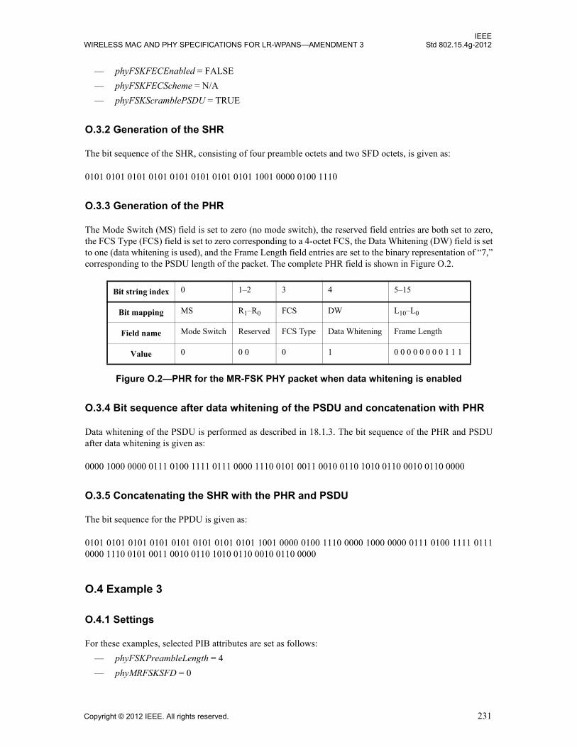
IEEEWIRELESS MAC AND PHY SPECIFICATIONS FOR LR-WPANS—AMENDMENT 3 Std 802.15.4g-2012
— phyFSKFECEnabled = FALSE
— phyFSKFECScheme = N/A
— phyFSKScramblePSDU = TRUE
O.3.2 Generation of the SHR
The bit sequence of the SHR, consisting of four preamble octets and two SFD octets, is given as:
0101 0101 0101 0101 0101 0101 0101 0101 1001 0000 0100 1110
O.3.3 Generation of the PHR
The Mode Switch (MS) field is set to zero (no mode switch), the reserved field entries are both set to zero, the FCS Type (FCS) field is set to zero corresponding to a 4-octet FCS, the Data Whitening (DW) field is set to one (data whitening is used), and the Frame Length field entries are set to the binary representation of “7,” corresponding to the PSDU length of the packet. The complete PHR field is shown in Figure O.2.
O.3.4 Bit sequence after data whitening of the PSDU and concatenation with PHR
Data whitening of the PSDU is performed as described in 18.1.3. The bit sequence of the PHR and PSDU after data whitening is given as:
0000 1000 0000 0111 0100 1111 0111 0000 1110 0101 0011 0010 0110 1010 0110 0010 0110 0000
O.3.5 Concatenating the SHR with the PHR and PSDU
The bit sequence for the PPDU is given as:
0101 0101 0101 0101 0101 0101 0101 0101 1001 0000 0100 1110 0000 1000 0000 0111 0100 1111 0111 0000 1110 0101 0011 0010 0110 1010 0110 0010 0110 0000
O.4 Example 3
O.4.1 Settings
For these examples, selected PIB attributes are set as follows:
— phyFSKPreambleLength = 4
— phyMRFSKSFD = 0
Bit string index 0 1–2 3 4 5–15
Bit mapping MS R1–R0 FCS DW L10–L0
Field name Mode Switch Reserved FCS Type Data Whitening Frame Length
Value 0 0 0 0 1 0 0 0 0 0 0 0 0 1 1 1
Figure O.2—PHR for the MR-FSK PHY packet when data whitening is enabled
Copyright © 2012 IEEE. All rights reserved. 231

IEEEStd 802.15.4g-2012 LOCAL AND METROPOLITAN AREA NETWORKS—PART 15.4:
— phyFSKFECEnabled = TRUE
— phyFSKFECScheme = 1
— phyFSKScramblePSDU = TRUE
— phyFSKFECInterleavingRSC = TRUE
O.4.2 Generation of the SHR
The bit sequence of the SHR, consisting of four preamble octets and two SFD octets, is given as:
0101 0101 0101 0101 0101 0101 0101 0101 0110 1111 0100 1110
O.4.3 Generation of the PHR
The bit sequence of the PHR is generated as in Figure O.2 and is:
0000 1000 0000 0111
O.4.4 Concatenating the PHR, PSDU, tail bits, and pad bits
Concatenation of the PHR, PSDU, tail bits, and pad bits is performed as described in 18.1.2.4. After concatenation, the bit sequence is given as:
0000 1000 0000 0111 0100 0000 0000 0000 0101 0110 0101 1101 0010 1001 1111 1010 0010 1000 0100 1011
O.4.5 Encoding of the bit sequence
Convolutional coding is performed as described in 18.1.2.4. The bit sequence after convolutional coding is given as:
0000 0000 1110 1000 0010 1000 0001 1111 0011 1010 0000 1010 0000 1010 0000 1010 0011 0011 1001 0100 0001 0001 0101 0011 0000 1110 0110 1001 1101 0101 1110 1100 1010 1110 1100 1010 0011 0000 1110 0101
O.4.6 Interleaving of the bit sequence
Interleaving is performed as described in 18.1.2.5. The bit sequence after interleaving is given as:
1100 0000 1110 1000 0110 1000 0000 1100 1010 1010 1010 1010 0000 0011 0000 0000 1101 0011 0000 0100 0101 0111 0100 1000 0001 0110 1101 1011 1001 1000 1111 0100 0100 1010 0100 1011 1011 0010 1100 1110
232 Copyright © 2012 IEEE. All rights reserved.

IEEEWIRELESS MAC AND PHY SPECIFICATIONS FOR LR-WPANS—AMENDMENT 3 Std 802.15.4g-2012
O.4.7 Bit sequence after data whitening of the PSDU
Data whitening of the PSDU is performed as described in 18.1.3. The bit sequence after data whitening is given as:
1100 0000 1110 1000 0110 1000 0000 1100 1010 0101 1101 1010 1011 0000 0110 1111 1001 0000 1001 1100 0001 1111 1110 0110 1010 1010 0100 1100 1010 0000 1110 1001 1001 1001 1001 1111 0001 0010 1001 1011
O.4.8 Concatenating the SHR with the PHR and PSDU
The bit sequence for the PPDU is given as:
0101 0101 0101 0101 0101 0101 0101 0101 0110 1111 0100 1110 1100 0000 1110 1000 0110 1000 0000 1100 1010 0101 1101 1010 1011 0000 0110 1111 1001 0000 1001 1100 0001 1111 1110 0110 1010 1010 0100 1100 1010 0000 1110 1001 1001 1001 1001 1111 0001 0010 1001 1011
O.5 Example 4
For this example, selected PIB attributes are set as follows:
— phyFSKFECEnabled = TRUE
— phyFSKFECScheme = 0
— phyFSKScramblePSDU = FALSE
— phyMRFSKSFD = 1
O.5.1 Generation of the SHR
The bit sequence of the SHR, consisting of four preamble octets and two SFD octets, is given as:
0101 0101 0101 0101 0101 0101 0101 0101 0110 0011 0010 1101
O.5.2 Generation of the PHR
The bit sequence of the PHR is generated as in Figure O.1 and is:
0000 0000 0000 0111
O.5.3 Concatenating the PHR, PSDU, tail bits, and pad bits
Concatenation of the PHR, PSDU, tail bits, and pad bits is performed as described in 18.1.2.4. After concatenation, the bit sequence is given as:
0000 0000 0000 0111 0100 0000 0000 0000 0101 0110 0101 1101 0010 1001 1111 1010 0010 1000 0000 1011
Copyright © 2012 IEEE. All rights reserved. 233
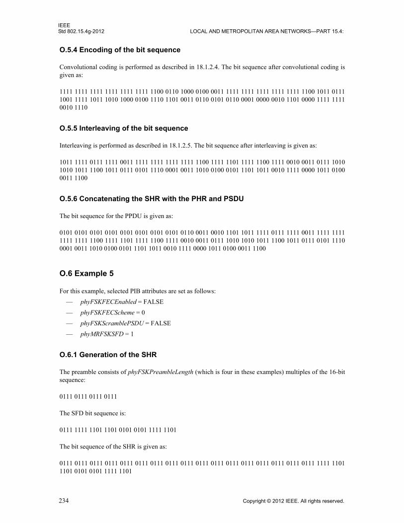
IEEEStd 802.15.4g-2012 LOCAL AND METROPOLITAN AREA NETWORKS—PART 15.4:
O.5.4 Encoding of the bit sequence
Convolutional coding is performed as described in 18.1.2.4. The bit sequence after convolutional coding is given as:
1111 1111 1111 1111 1111 1111 1100 0110 1000 0100 0011 1111 1111 1111 1111 1111 1100 1011 0111 1001 1111 1011 1010 1000 0100 1110 1101 0011 0110 0101 0110 0001 0000 0010 1101 0000 1111 1111 0010 1110
O.5.5 Interleaving of the bit sequence
Interleaving is performed as described in 18.1.2.5. The bit sequence after interleaving is given as:
1011 1111 0111 1111 0011 1111 1111 1111 1111 1100 1111 1101 1111 1100 1111 0010 0011 0111 1010 1010 1011 1100 1011 0111 0101 1110 0001 0011 1010 0100 0101 1101 1011 0010 1111 0000 1011 0100 0011 1100
O.5.6 Concatenating the SHR with the PHR and PSDU
The bit sequence for the PPDU is given as:
0101 0101 0101 0101 0101 0101 0101 0101 0110 0011 0010 1101 1011 1111 0111 1111 0011 1111 1111 1111 1111 1100 1111 1101 1111 1100 1111 0010 0011 0111 1010 1010 1011 1100 1011 0111 0101 1110 0001 0011 1010 0100 0101 1101 1011 0010 1111 0000 1011 0100 0011 1100
O.6 Example 5
For this example, selected PIB attributes are set as follows:
— phyFSKFECEnabled = FALSE
— phyFSKFECScheme = 0
— phyFSKScramblePSDU = FALSE
— phyMRFSKSFD = 1
O.6.1 Generation of the SHR
The preamble consists of phyFSKPreambleLength (which is four in these examples) multiples of the 16-bit sequence:
0111 0111 0111 0111
The SFD bit sequence is:
0111 1111 1101 1101 0101 0101 1111 1101
The bit sequence of the SHR is given as:
0111 0111 0111 0111 0111 0111 0111 0111 0111 0111 0111 0111 0111 0111 0111 0111 0111 1111 1101 1101 0101 0101 1111 1101
234 Copyright © 2012 IEEE. All rights reserved.

IEEEWIRELESS MAC AND PHY SPECIFICATIONS FOR LR-WPANS—AMENDMENT 3 Std 802.15.4g-2012
O.6.2 Generation of the PHR
The bit sequence of the PHR is generated as in Figure O.1 and is:
0000 0000 0000 0111
O.6.3 Generation of the PSDU
The bit sequence of the PSDU is:
0100 0000 0000 0000 0101 0110 0101 1101 0010 1001 1111 1010 0010 1000
O.6.4 Concatenating the SHR with the PHR and PSDU
The bit sequence for the PPDU is given as:
0111 0111 0111 0111 0111 0111 0111 0111 0111 0111 0111 0111 0111 0111 0111 0111 0111 1111 1101 1101 0101 0101 1111 1101 0000 0000 0000 0111 0100 0000 0000 0000 0101 0110 0101 1101 0010 1001 1111 1010 0010 1000
O.7 Example 6
O.7.1 Settings
For this example, selected PIB attributes are set as follows:
— phyFSKPreambleLength = 4
— phyMRFSKSFD = 0
— phyFSKFECEnabled = TRUE
— phyFSKFECScheme = 1
— phyFSKScramblePSDU = TRUE
— phyFSKFECInterleavingRSC = TRUE
O.7.2 Generation of the SHR
The bit sequence of the SHR, consisting of eight preamble octets and four SFD octets, is given as:
0111 0111 0111 0111 0111 0111 0111 0111 0111 0111 0111 0111 0111 0111 0111 0111 0111 1101 1111 1111 0111 0101 1111 1101
O.7.3 Generation of the PHR
The bit sequence of the PHR is generated as in Figure O.2 and is:
0000 1000 0000 0111
Copyright © 2012 IEEE. All rights reserved. 235

IEEEStd 802.15.4g-2012
O.7.4 Concatenating the PHR, PSDU, tail bits, and pad bits
Concatenation of the PHR, PSDU, tail bits, and pad bits is performed as described in 18.1.2.4. Afterconcatenation, the bit sequence is given as:
0000 1000 0000 0111 0100 0000 0000 0000 0101 0110 0101 1101 0010 1001 1111 1010 0010 1000 01001011
O.7.5 Encoding of the bit sequence
Convolutional coding is performed as described in 18.1.2.4. The bit sequence after convolutional coding isgiven as:
0000 0000 1110 1000 0010 1000 0001 1111 0011 1010 0000 1010 0000 1010 0000 1010 0011 0011 10010100 0001 0001 0101 0011 0000 1110 0110 1001 1101 0101 1110 1100 1010 1110 1100 1010 0011 00001110 0101
O.7.6 Interleaving of the bit sequence
Interleaving is performed as described in 18.1.2.5. The bit sequence after interleaving is given as:
1100 0000 1110 1000 0110 1000 0000 1100 1010 1010 1010 1010 0000 0011 0000 0000 1101 0011 00000100 0101 0111 0100 1000 0001 0110 1101 1011 1001 1000 1111 0100 0100 1010 0100 1011 1011 00101100 1110
O.7.7 Bit sequence after data whitening of the PSDU
Data whitening of the PSDU is performed as described in 18.1.3. The bit sequence after data whitening isgiven as:
1100 0000 1110 1000 0110 1000 0000 1100 1010 0101 1101 1010 1011 0000 0110 1111 1001 0000 10011100 0001 1111 1110 0110 1010 1010 0100 1100 1010 0000 1110 1001 1001 1001 1001 1111 0001 00101001 1011
O.7.8 Concatenating the SHR with the PHR and PSDU
The bit sequence for the PPDU is given as:
0111 0111 0111 0111 0111 0111 0111 0111 0111 0111 0111 0111 0111 0111 0111 0111 0111 1101 11111111 0111 0101 1111 1101 1100 0000 1110 1000 0110 1000 0000 1100 1010 0101 1101 1010 1011 00000110 1111 1001 0000 1001 1100 0001 1111 1110 0110 1010 1010 0100 1100 1010 0000 1110 1001 10011001 1001 1111 0001 0010 1001 1011
236 Copyright © 2012 IEEE. All rights reserved.