8000 series owner’s manual - truck bodies | stahl … · 4 s safety 8000 series owner’s manual...
TRANSCRIPT

MayMayMayMay 22220000, 20, 20, 20, 2011111111
8000 Series Owner’s Manual
2
TABLE OF CONTENTS 8000 SERIES OWNER’S MANUAL
s
TABLE OF CONTENTS 2
SAFETY 3
OPERATION 6
MAINTENANCE 11
SPECIFICATIONS 13
TROUBLESHOOTING 16
MOUNTING INSTRUCTIONS 17
PARTS 22
SCHEMATICS 33
WARRANTY 35
FOR THE LOCATION OF YOUR NEAREST DISTRIBUTOR CAFOR THE LOCATION OF YOUR NEAREST DISTRIBUTOR CAFOR THE LOCATION OF YOUR NEAREST DISTRIBUTOR CAFOR THE LOCATION OF YOUR NEAREST DISTRIBUTOR CALL 330LL 330LL 330LL 330----264264264264----7441744174417441
3 s
SAFETY 8000 SERIES OWNER’S MANUAL
---- It is YOUR responsibility to maintain and operate this crane safely It is YOUR responsibility to maintain and operate this crane safely It is YOUR responsibility to maintain and operate this crane safely It is YOUR responsibility to maintain and operate this crane safely ---- The following words and symbols will be used in your owner’s manual: ! DANGER DANGER DANGER DANGER ! Indicates immediate danger and that special precautions are necessary. ! CAUTIOCAUTIOCAUTIOCAUTION N N N ! Warns against potential hazards or cautions against unsafe practices. Your s crane is designed to meet all applicable government safety standards. Warranty will be voided if the crane is misused due to:
• Overloading
• Abuse
• Lack of (or improper) maintenance
• Unauthorized modification
! CAUTION !! CAUTION !! CAUTION !! CAUTION !
Operate your 8000 crane within the lifting capacities specified. Exceeding the lifting capacity for a given boom length can cause tipping or structural failure. Only the s “New Machinery and Equipment” warranty shown on the last page of this manual is valid with this crane. No other warranty—verbal, written, or implied—is valid with this crane. Treat your s crane with respect and service it regularly. These two things can add up to a safer working environment and longer equipment life.
! CAUTION !! CAUTION !! CAUTION !! CAUTION !
Note locations of Danger, Caution, and Lift Capacity decals on the 8000 crane. Read and understand each of these before attempting to operate the crane. If any of these labels are missing or cannot be read, contact your s distributor for immediate replacement.
4 s
SAFETY 8000 SERIES OWNER’S MANUAL
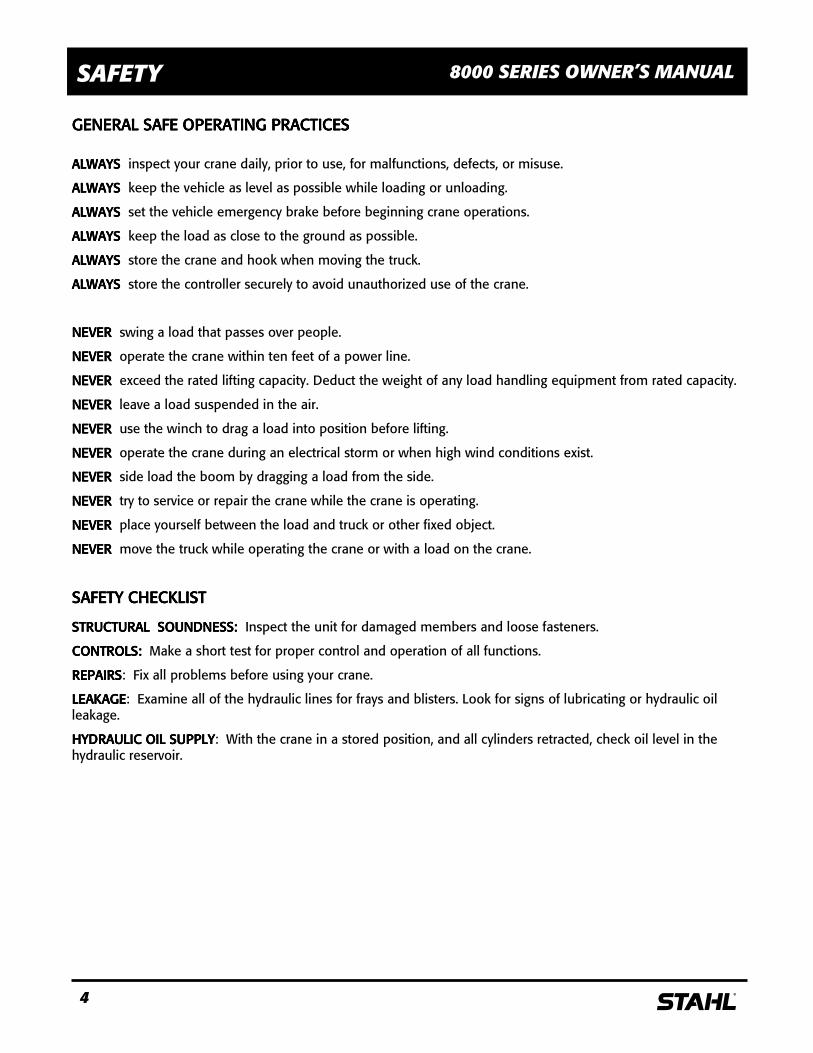
GENERAL SAFE OPERATIGENERAL SAFE OPERATIGENERAL SAFE OPERATIGENERAL SAFE OPERATING PRACTICESNG PRACTICESNG PRACTICESNG PRACTICES
ALWAYS ALWAYS ALWAYS ALWAYS inspect your crane daily, prior to use, for malfunctions, defects, or misuse.
ALWAYS ALWAYS ALWAYS ALWAYS keep the vehicle as level as possible while loading or unloading.
ALWAYS ALWAYS ALWAYS ALWAYS set the vehicle emergency brake before beginning crane operations.
ALWAYS ALWAYS ALWAYS ALWAYS keep the load as close to the ground as possible.
ALWAYS ALWAYS ALWAYS ALWAYS store the crane and hook when moving the truck.
ALWAYS ALWAYS ALWAYS ALWAYS store the controller securely to avoid unauthorized use of the crane.
NEVER NEVER NEVER NEVER swing a load that passes over people.
NEVER NEVER NEVER NEVER operate the crane within ten feet of a power line.
NEVER NEVER NEVER NEVER exceed the rated lifting capacity. Deduct the weight of any load handling equipment from rated capacity.
NEVER NEVER NEVER NEVER leave a load suspended in the air.
NEVER NEVER NEVER NEVER use the winch to drag a load into position before lifting.
NEVER NEVER NEVER NEVER operate the crane during an electrical storm or when high wind conditions exist.
NEVER NEVER NEVER NEVER side load the boom by dragging a load from the side.
NEVER NEVER NEVER NEVER try to service or repair the crane while the crane is operating.
NEVER NEVER NEVER NEVER place yourself between the load and truck or other fixed object.
NEVER NEVER NEVER NEVER move the truck while operating the crane or with a load on the crane.
SAFETY CHECKLISTSAFETY CHECKLISTSAFETY CHECKLISTSAFETY CHECKLIST
STRUCTURALSTRUCTURALSTRUCTURALSTRUCTURAL SOUNDNESS: SOUNDNESS: SOUNDNESS: SOUNDNESS: Inspect the unit for damaged members and loose fasteners.
CONTROLS: CONTROLS: CONTROLS: CONTROLS: Make a short test for proper control and operation of all functions.
REPAIRSREPAIRSREPAIRSREPAIRS: Fix all problems before using your crane.
LEAKAGELEAKAGELEAKAGELEAKAGE: Examine all of the hydraulic lines for frays and blisters. Look for signs of lubricating or hydraulic oil leakage.
HYDRAULIC OIL SUPPLYHYDRAULIC OIL SUPPLYHYDRAULIC OIL SUPPLYHYDRAULIC OIL SUPPLY: With the crane in a stored position, and all cylinders retracted, check oil level in the hydraulic reservoir.
5 s
SAFETY 8000 SERIES OWNER’S MANUAL
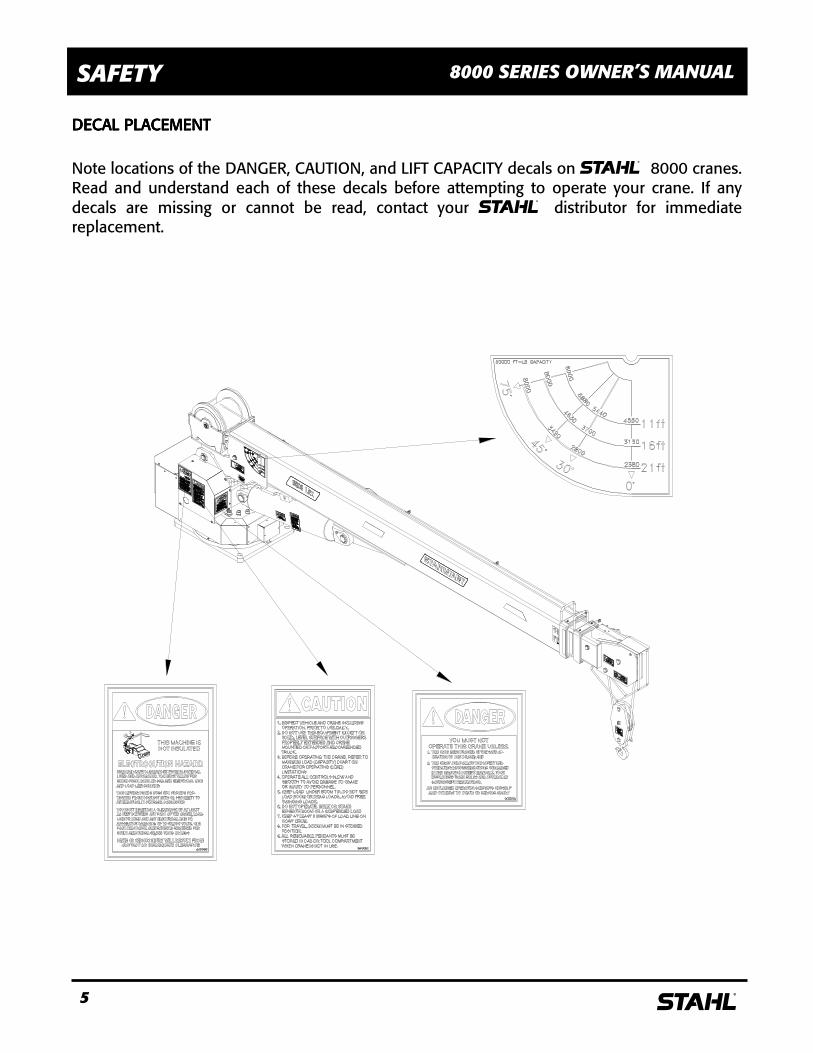
DECAL PLACEMENTDECAL PLACEMENTDECAL PLACEMENTDECAL PLACEMENT
Note locations of the DANGER, CAUTION, and LIFT CAPACITY decals on s 8000 cranes. Read and understand each of these decals before attempting to operate your crane. If any decals are missing or cannot be read, contact your s distributor for immediate replacement.

6 s
OPERATION 8000 SERIES OWNER’S MANUAL
LOAD CAPACITIESLOAD CAPACITIESLOAD CAPACITIESLOAD CAPACITIES 8000 LRX8000 LRX8000 LRX8000 LRX----20H20H20H20H
MMMMEASURED IN POUNDSEASURED IN POUNDSEASURED IN POUNDSEASURED IN POUNDS CRANE RATING: CRANE RATING: CRANE RATING: CRANE RATING: 50505050,000 FT./LB.,000 FT./LB.,000 FT./LB.,000 FT./LB.
DISTANCE IN FEETDISTANCE IN FEETDISTANCE IN FEETDISTANCE IN FEET
NOTE: Load capacities are based on 85% of tipping when all outriggers are extended and have firm
contact with a solid surface. Vehicles must have proper axle load distribution and crane must be mounted
in accordance with manufacturer’s instructions.
7 s
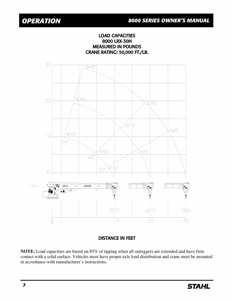
OPERATION 8000 SERIES OWNER’S MANUAL
LOAD CAPACITIESLOAD CAPACITIESLOAD CAPACITIESLOAD CAPACITIES 8000 LRX8000 LRX8000 LRX8000 LRX----30H30H30H30H
MEASURED IN POUNDSMEASURED IN POUNDSMEASURED IN POUNDSMEASURED IN POUNDS CRANE RATING: 50,000 FT./LB.CRANE RATING: 50,000 FT./LB.CRANE RATING: 50,000 FT./LB.CRANE RATING: 50,000 FT./LB.
DISTANCE IN FEETDISTANCE IN FEETDISTANCE IN FEETDISTANCE IN FEET
NOTE: Load capacities are based on 85% of tipping when all outriggers are extended and have firm
contact with a solid surface. Vehicles must have proper axle load distribution and crane must be mounted
in accordance with manufacturer’s instructions.
8 s
OPERATION 8000 SERIES OWNER’S MANUAL
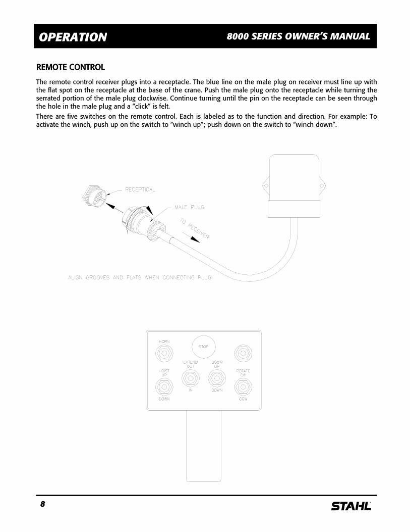
REMOTE CONTROLREMOTE CONTROLREMOTE CONTROLREMOTE CONTROL
The remote control receiver plugs into a receptacle. The blue line on the male plug on receiver must line up with the flat spot on the receptacle at the base of the crane. Push the male plug onto the receptacle while turning the serrated portion of the male plug clockwise. Continue turning until the pin on the receptacle can be seen through the hole in the male plug and a “click” is felt. There are five switches on the remote control. Each is labeled as to the function and direction. For example: To activate the winch, push up on the switch to “winch up”; push down on the switch to “winch down”.
9 s
OPERATION 8000 SERIES OWNER’S MANUAL
The 8000 crane is designed to provide excellent service if operated within the maximum allowable load specifications stated on the unit’s “Angle Indicator Plate” located on either side of the boom. load charts are also included on pages 6 and 7. The load information charts should be studied before operating the crane. Exceeding the stated load limit can cause tipping or structural failure. You should familiarize yourself with proper operation procedures to avoid overloading the crane. As an example: If a load of 5000 pounds were lifted at an 11’ boom length at 30°, lowering the boom would cause an overload situation.
The 8000 crane is relatively simple to operate. Prior to field use, you should familiarize yourself with the controls and how the unit reacts to the controls. Practice operations should be performed with a light test weight progressing to a heavier test weight.
LIFTING OVER 4000 POUNDSLIFTING OVER 4000 POUNDSLIFTING OVER 4000 POUNDSLIFTING OVER 4000 POUNDS
A “two-part” line must be used whenever the load is 4000400040004000 pounds pounds pounds pounds or greater. In order to “two-part” the line:
• Connect the winch cable eye to the pin on the bottom of the manually extendible boom section.
• Insert cable through the snatch block by removing the cotter pin and disassembling.
• Reassemble the snatch block. Be sure to reinsert the cotter pin in the snatch block.
You should also use a “two-part” line for loads under 4000 pounds if you want to slow down the line speed of the cable. LOAD LIFTINGLOAD LIFTINGLOAD LIFTINGLOAD LIFTING
It must be understood that all load ratings are formulated on 85% of tipping. Tipping is defined as a tire breaking contact with the ground. Furthermore, all load ratings are dependent upon compliance with the following:
• The unit has been correctly installed in accordance with chassis requirements and truck body manufacturer’s specifications.
• The intended operation is carried out on a level, solid surface with proper outrigger placement.
10 s
OPERATION 8000 SERIES OWNER’S MANUAL
TASK PERFORMANCETASK PERFORMANCETASK PERFORMANCETASK PERFORMANCE
1. Position the 8000 crane as close to the job as possible on a firm, dry, and level surface. Avoid overhead obstruction on the work side of the unit.
2. Set the parking brake.
3. Extend and lower the outriggers until firm ground contact is made. On soft ground, use bearing pads to prevent sinking or tipping.
4. Run the winch line out before extending the boom.
5. Make sure the connection to the load is secure and will not come loose when lifting the load.
OVERLOAD PROTECTIONOVERLOAD PROTECTIONOVERLOAD PROTECTIONOVERLOAD PROTECTION
The 8000 crane is equipped with a counterbalance valve inside the lift cylinder to protect against overloading. In an overload condition, the boom will not elevate. Attempts to winch the load will cause a downward feathering of the boom until the overload condition is reduced. The counterbalance valve will also keep the boom from coming down in the unlikely event of a rupture to the hydraulic hoses that supply oil to the lift cylinder.
A pressure sensitive switch is also located in the lifting cylinder that can detect an overload situation. This causes a shutdown of the winch up, boom extension out, and boom lower functions, and automatically resets after the crane has been moved out of overload position.
An anti-two block feature is also provided on LRX models.
ROTATION STOPROTATION STOPROTATION STOPROTATION STOP
A stop to prevent the unit from rotating continuously is located on the crane base. The stop is installed so that a full 360° plus is obtained. A stop lever is attached to the turret and extends so that it will contact the rotation stop on the base assembly. Do not remove the stop assembly. Continuous rotation will result in damage to the wiring harness and/or hydraulic hoses.
SPEED CONTROL OPERATIONSPEED CONTROL OPERATIONSPEED CONTROL OPERATIONSPEED CONTROL OPERATION
The 8000 LRX is equipped with trigger activated proportional hydraulic controls. The flow control valve is located in the valve manifold block. The trigger is located on the remote control transmitter.
RELIEF VALVESRELIEF VALVESRELIEF VALVESRELIEF VALVES
The 8000 crane requires a relief valve located at the reservoir to maintain crane operating pressure at 2850 PSI. This relief valve is not supplied unless using a s hydraulic reservoir. It is the customer’s responsibility to provide this relief valve when using a reservoir not supplied by s. The main function of this relief valve is to prevent overloading of the system if the boom is inadvertently rotated against an immovable object, while one of the other hydraulic functions is also being used. The relief valves would not normally require adjustment, but if the correct relief valve setting is suspect, refer to the maintenance section of this manual for the proper adjustment and testing procedure.
11 s
MAINTENANCE 8000 SERIES OWNER’S MANUAL
Proper maintenance on a regular schedule is essential to keep the unit operating at peak efficiency.
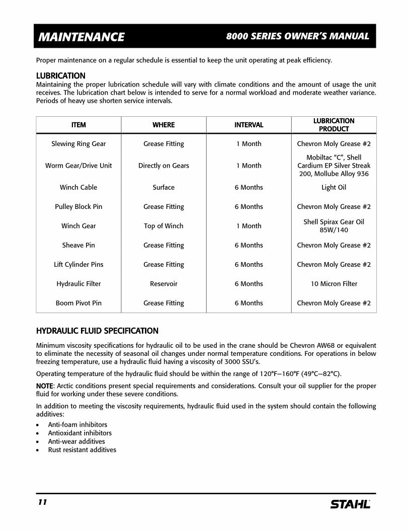
LUBRICATIONLUBRICATIONLUBRICATIONLUBRICATION Maintaining the proper lubrication schedule will vary with climate conditions and the amount of usage the unit receives. The lubrication chart below is intended to serve for a normal workload and moderate weather variance. Periods of heavy use shorten service intervals.
ITEMITEMITEMITEM WHEREWHEREWHEREWHERE INTERVALINTERVALINTERVALINTERVAL LUBRICATIONLUBRICATIONLUBRICATIONLUBRICATION PRODUCTPRODUCTPRODUCTPRODUCT
Slewing Ring Gear Grease Fitting 1 Month Chevron Moly Grease #2
Worm Gear/Drive Unit Directly on Gears 1 Month Mobiltac “C”, Shell
Cardium EP Silver Streak 200, Mollube Alloy 936
Winch Cable Surface 6 Months Light Oil
Pulley Block Pin Grease Fitting 6 Months Chevron Moly Grease #2
Winch Gear Top of Winch 1 Month Shell Spirax Gear Oil 85W/140
Sheave Pin Grease Fitting 6 Months Chevron Moly Grease #2
Lift Cylinder Pins Grease Fitting 6 Months Chevron Moly Grease #2
Hydraulic Filter Reservoir 6 Months 10 Micron Filter
Boom Pivot Pin Grease Fitting 6 Months Chevron Moly Grease #2
HYDRAULIC FLUID SPECIFICATIONHYDRAULIC FLUID SPECIFICATIONHYDRAULIC FLUID SPECIFICATIONHYDRAULIC FLUID SPECIFICATION
Minimum viscosity specifications for hydraulic oil to be used in the crane should be Chevron AW68 or equivalent to eliminate the necessity of seasonal oil changes under normal temperature conditions. For operations in below freezing temperature, use a hydraulic fluid having a viscosity of 3000 SSU’s.
Operating temperature of the hydraulic fluid should be within the range of 120°F—160°F (49°C—82°C).
NOTENOTENOTENOTE: Arctic conditions present special requirements and considerations. Consult your oil supplier for the proper fluid for working under these severe conditions.
In addition to meeting the viscosity requirements, hydraulic fluid used in the system should contain the following additives:
• Anti-foam inhibitors • Antioxidant inhibitors • Anti-wear additives • Rust resistant additives
12 s
MAINTENANCE 8000 SERIES OWNER’S MANUAL
PURGING AIR FROM THE SYSTEPURGING AIR FROM THE SYSTEPURGING AIR FROM THE SYSTEPURGING AIR FROM THE SYSTEMMMM
Air that is trapped in the cylinder will cause an erratic “bumpy” condition. To expel the air, hold the affected control open after the function has “bottomed out”. Move the function in the opposite direction and again hold the control open. Attempt to operate the crane in a normal manner to determine if the air has been purged. When purging is complete, reevaluate hydraulic fluid level and add fluid if necessary.
HYDRAULIC OIL DETERIORATIONHYDRAULIC OIL DETERIORATIONHYDRAULIC OIL DETERIORATIONHYDRAULIC OIL DETERIORATION
Contamination of the hydraulic oil by solvents, water, dust or other abrasives will result in premature breakdown of the oil’s anti-foam, lubrication, anti-rust and viscosity properties. Periodically, a sample of the hydraulic oil in the system should be drawn off and its condition checked for breakdown. To check quality:
1. Place oil sample in a clean glass.
2. Smell oil to detect a burnt or rancid odor.
3. Examine the oil for a cloudy or dark color. 4. Allow the sample to stand for several minutes and inspect it for water, which will settle to the bottom.
When any of the results above are observed, the system should be purged to the bottom and filled with new oil.
HYDRAULIC SYSTEM PURGINGHYDRAULIC SYSTEM PURGINGHYDRAULIC SYSTEM PURGINGHYDRAULIC SYSTEM PURGING
The oil should be changed after 600 hours600 hours600 hours600 hours of operation or every six monthssix monthssix monthssix months, whichever comes first. The procedure for purging the system is as follows:
1. Locate the unit in an area that provides solid, level footing and space to accommodate the full operating range of the crane.
2. Stabilize the unit with the outriggers. Move the crane to either side of the truck and extend the lift cylinder.
3. Drain the hydraulic fluid from the reservoir and clean the suction line filter.
4. Remove the reservoir return line. Refill the reservoir with Chevron AW68 or equivalent. Direct the return line into a sump waste container.
5. Rotate the crane 90 degrees, retract the extension boom, lower the main boom and operate the winch up and down for approximately ten seconds.
6. All components are now purged. Replace the return line filter cartridge and reinstall the return line to the reservoir.
7. Check the reservoir fluid level and add fluid to within one half inch (1/2”) of the top. The boom elevation and extension cylinders must be fully retracted when refilling the reservoir.
13 s
SPECIFICATIONS 8000 SERIES OWNER’S MANUAL
FEATURESFEATURESFEATURESFEATURES • Crane Rating: 50,000-ft/lb capacity.
• Hydraulic boom extension provides reach up to 30’.
• Hydraulic winch for durable operation.
• Self-lubricating Nylatron bearing allows smooth operation of inner and outer booms.
• Multifunction, proportional radio remote control provides safe operation up to 500’ away.
• Electrical solenoid-operated valves.
SPECIFICATSPECIFICATSPECIFICATSPECIFICATIONSIONSIONSIONS 8000800080008000 LRXLRXLRXLRX----20H20H20H20H 8000800080008000 LRXLRXLRXLRX----30H30H30H30H • Extension: Hydraulic 11’ to 21’. Hydraulic 14’ to 30’
• Lifting Height Above Base: 19’ 28’
• Weight: 2100 lbs. 2500 lbs.
• Length: 13’-3” 16’-3”
• Width: 25”
• Height: 36”
• Base Dimensions: 23” x 19”
• Rotation System: 370° non-continuous hydraulic on turntable bearing with self-locking worm drive.
• Remote Control: Proportional radio remote control unit with up to of 500’ range.
• Winch Cable: 120’ of 3/8” aircraft cable, with latch hook traveling block and down haul weight.
• Rotation Speed: 1 RPM.
• Boom Elevation Speed: -5° to +75° - 20 seconds.
• Boom Extension Speed: 11’ to 21’ - 18 seconds.
• Winch Line Speed: 60’ per minute - single line.
• Min. Chassis Req.: 18,000 GVWR.
HYDRAULIC REQUIREMENTSHYDRAULIC REQUIREMENTSHYDRAULIC REQUIREMENTSHYDRAULIC REQUIREMENTS
• Crane requires 6 Gallon Per Minute at 2850 PSI.
• 18-gallon capacity hydraulic reservoir optional.
• Open centered, full pressure hydraulic system.
A hydraulic power source must be provided if an adequate system is unavailable on vehicle.
OUTRIGGER REQUIREMENTOUTRIGGER REQUIREMENTOUTRIGGER REQUIREMENTOUTRIGGER REQUIREMENT Truck must be equipped with heavy-duty outrigger.
14 s
SPECIFICATIONS 8000 SERIES OWNER’S MANUAL
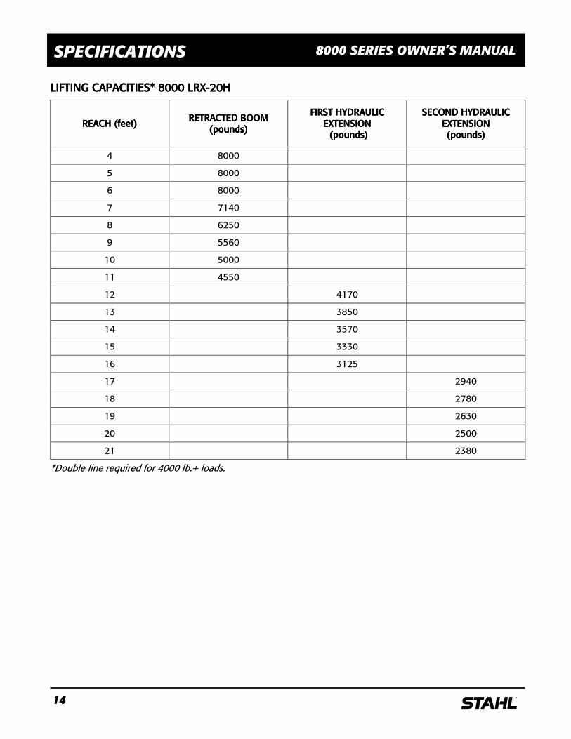
LIFTING CAPACITIES* 8000 LRXLIFTING CAPACITIES* 8000 LRXLIFTING CAPACITIES* 8000 LRXLIFTING CAPACITIES* 8000 LRX----20H20H20H20H
REACH (feet)REACH (feet)REACH (feet)REACH (feet) RETRACTED BOOM RETRACTED BOOM RETRACTED BOOM RETRACTED BOOM
(pounds)(pounds)(pounds)(pounds)
FIRST HYDRAULIC FIRST HYDRAULIC FIRST HYDRAULIC FIRST HYDRAULIC EXTENSIONEXTENSIONEXTENSIONEXTENSION (pounds) (pounds) (pounds) (pounds)
SECOND HYDRAULIC SECOND HYDRAULIC SECOND HYDRAULIC SECOND HYDRAULIC EXTENSION EXTENSION EXTENSION EXTENSION (pounds)(pounds)(pounds)(pounds)
4 8000
5 8000
6 8000
7 7140
8 6250
9 5560
10 5000
11 4550
12 4170
13 3850
14 3570
15 3330
16 3125
17 2940
18 2780
19 2630
20 2500
21 2380
*Double line required for 4000 lb.+ loads.
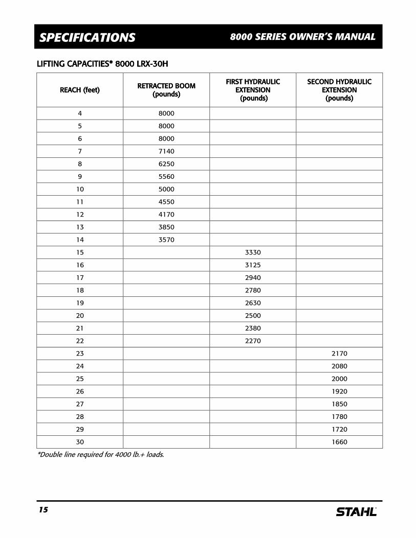
15 s
SPECIFICATIONS 8000 SERIES OWNER’S MANUAL
LIFTING CAPACITIES*LIFTING CAPACITIES*LIFTING CAPACITIES*LIFTING CAPACITIES* 8000 LRX 8000 LRX 8000 LRX 8000 LRX----30H30H30H30H
REACH (feet)REACH (feet)REACH (feet)REACH (feet) RETRACTED BOOM RETRACTED BOOM RETRACTED BOOM RETRACTED BOOM
(pounds)(pounds)(pounds)(pounds)
FIRST FIRST FIRST FIRST HYDRAULIC HYDRAULIC HYDRAULIC HYDRAULIC EEEEXTENSIONXTENSIONXTENSIONXTENSION (pounds) (pounds) (pounds) (pounds)
SECOND HYDRAULICSECOND HYDRAULICSECOND HYDRAULICSECOND HYDRAULIC EXTENSION EXTENSION EXTENSION EXTENSION (pounds)(pounds)(pounds)(pounds)
4 8000
5 8000
6 8000
7 7140
8 6250
9 5560
10 5000
11 4550
12 4170
13 3850
14 3570
15 3330
16 3125
17 2940
18 2780
19 2630
20 2500
21 2380
22 2270
23 2170
24 2080
25 2000
26 1920
27 1850
28 1780
29 1720
30 1660
*Double line required for 4000 lb.+ loads.
16 s
TROUBLESHOOTING 8000 SERIES OWNER’S MANUAL
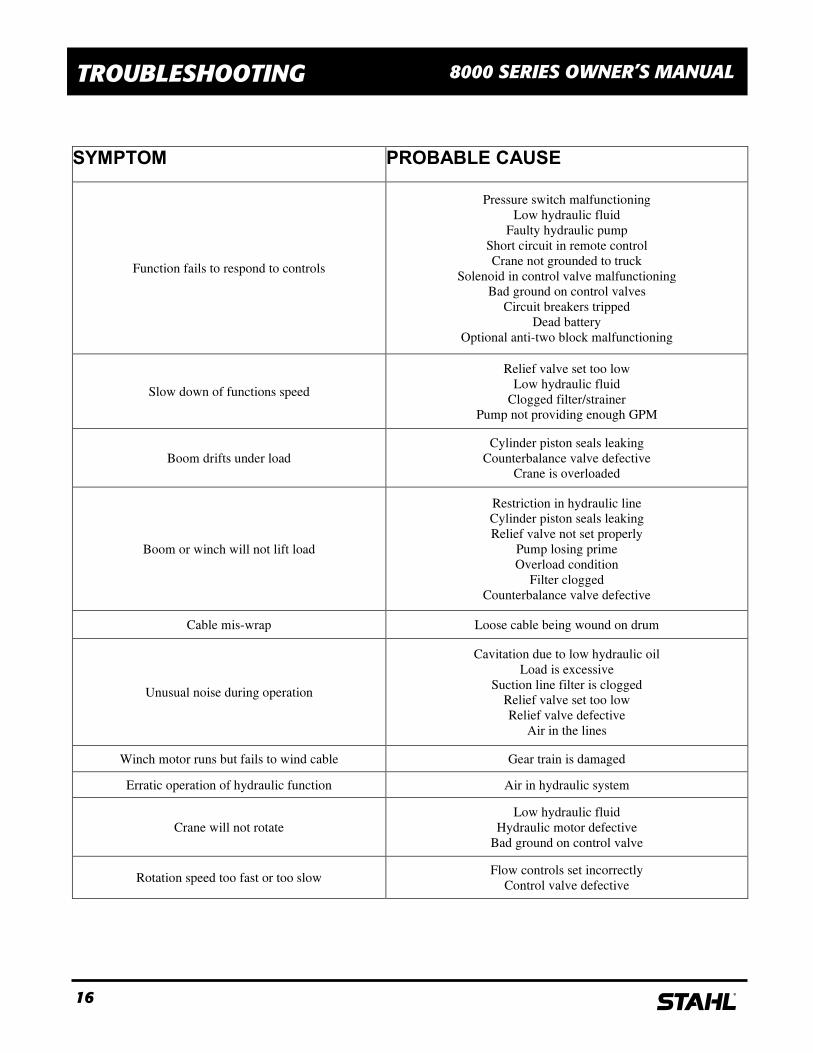
SYMPTOM PROBABLE CAUSE
Function fails to respond to controls
Pressure switch malfunctioning
Low hydraulic fluid
Faulty hydraulic pump
Short circuit in remote control
Crane not grounded to truck
Solenoid in control valve malfunctioning
Bad ground on control valves
Circuit breakers tripped
Dead battery
Optional anti-two block malfunctioning
Slow down of functions speed
Relief valve set too low
Low hydraulic fluid
Clogged filter/strainer
Pump not providing enough GPM
Boom drifts under load
Cylinder piston seals leaking
Counterbalance valve defective
Crane is overloaded
Boom or winch will not lift load
Restriction in hydraulic line
Cylinder piston seals leaking
Relief valve not set properly
Pump losing prime
Overload condition
Filter clogged
Counterbalance valve defective
Cable mis-wrap Loose cable being wound on drum
Unusual noise during operation
Cavitation due to low hydraulic oil
Load is excessive
Suction line filter is clogged
Relief valve set too low
Relief valve defective
Air in the lines
Winch motor runs but fails to wind cable Gear train is damaged
Erratic operation of hydraulic function Air in hydraulic system
Crane will not rotate
Low hydraulic fluid
Hydraulic motor defective
Bad ground on control valve
Rotation speed too fast or too slow Flow controls set incorrectly
Control valve defective
17 s
MOUNTING INSTRUCTIONS 8000 SERIES OWNER’S MANUAL
! CAUTION !
Improperly mounted cranes can injure people or damage property. These instructions describe installation of a s crane on a typical s service body. Contact the dealer for other service body/truck chassis combinations.
! CAUTION !
The truck chassis must be capable of safely supporting the entire chassis, body, crane, other equipment and the maximum capacity of the crane - 8000 pounds.
The 8000 crane must be installed on a truck chassis with a GVWR of at least 18,00 pounds greater than the curb weight of the complete vehicle. The curb weight is the total weight of the chassis, body, crane, and other equipment.
! CAUTION !
Never attach, change, or use unauthorized components on your s crane. This could result in failure of the crane (and possible injuries) and voids any warranty or liability.
! CAUTION !
MMMMOST SERVICE BODIES AOST SERVICE BODIES AOST SERVICE BODIES AOST SERVICE BODIES ARE NOT STRONG ENOUGHRE NOT STRONG ENOUGHRE NOT STRONG ENOUGHRE NOT STRONG ENOUGH TO MOUNT A CRANE TO MOUNT A CRANE TO MOUNT A CRANE TO MOUNT A CRANE!!!!
You must reinforce the compartment and floor before you mount the crane. Get help from the truck dealer or distributor if the s 8000 crane is installed on a non-s body, in another body/chassis combination or in a different location. It is recommended that a s crane body and outriggers be used with the 8000 crane. Consult the distributor for the proper body required for your application.
! CAUTION !
Never attach, change, or use unauthorized components on your s crane. This could result in failure of the crane (and possible injuries) and voids any warranty or liability.
18 s
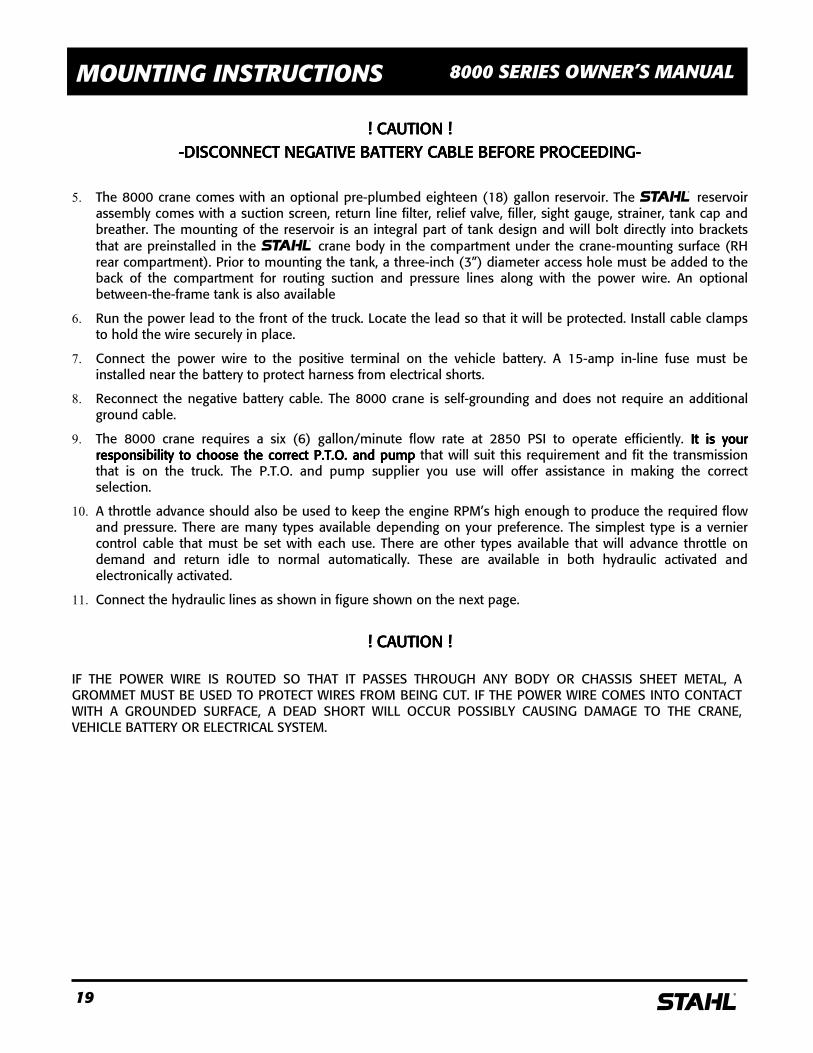
MOUNTING INSTRUCTIONS 8000 SERIES OWNER’S MANUAL
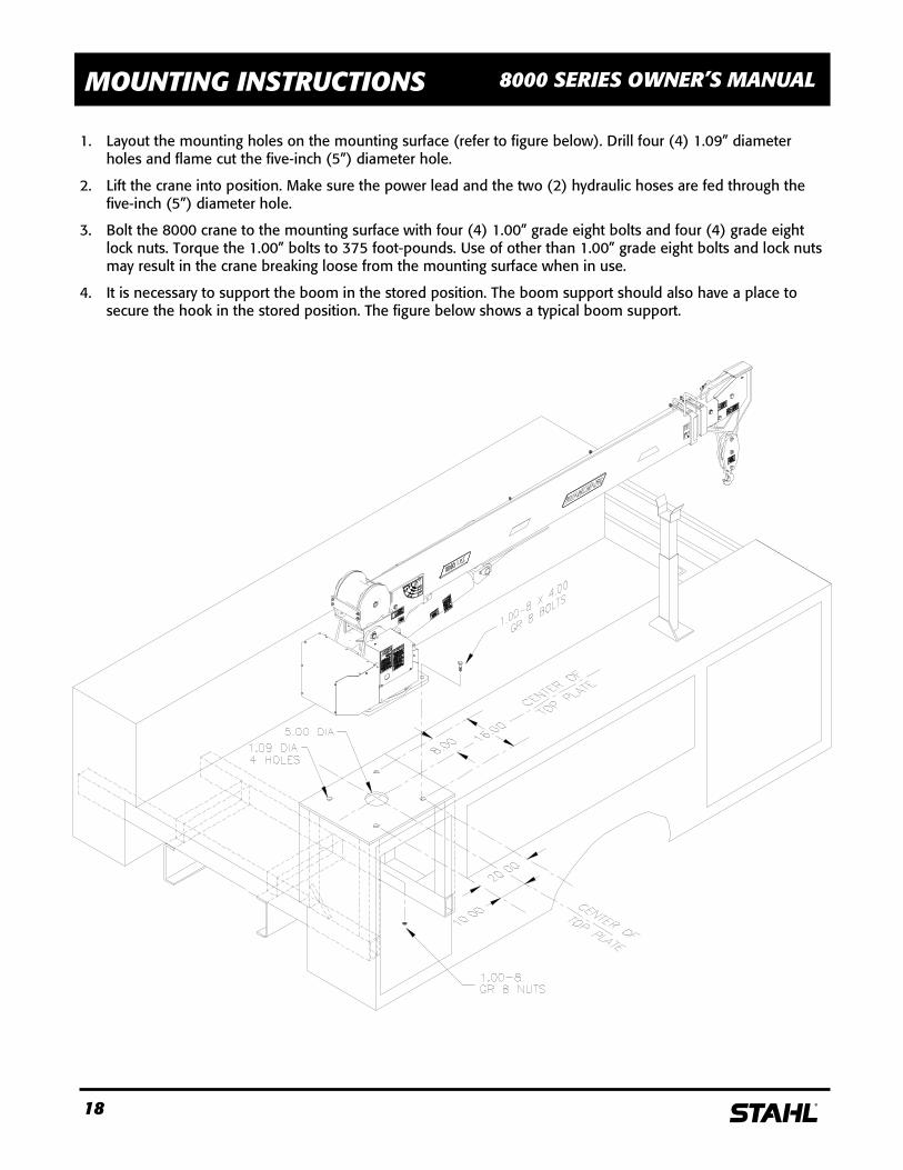
1. Layout the mounting holes on the mounting surface (refer to figure below). Drill four (4) 1.09” diameter
holes and flame cut the five-inch (5”) diameter hole.
2. Lift the crane into position. Make sure the power lead and the two (2) hydraulic hoses are fed through the five-inch (5”) diameter hole.
3. Bolt the 8000 crane to the mounting surface with four (4) 1.00” grade eight bolts and four (4) grade eight lock nuts. Torque the 1.00” bolts to 375 foot-pounds. Use of other than 1.00” grade eight bolts and lock nuts may result in the crane breaking loose from the mounting surface when in use.
4. It is necessary to support the boom in the stored position. The boom support should also have a place to secure the hook in the stored position. The figure below shows a typical boom support.
19 s
MOUNTING INSTRUCTIONS 8000 SERIES OWNER’S MANUAL
! CAUTION !! CAUTION !! CAUTION !! CAUTION !
----DISCONNECT NEGATIVE BATTERY CABLE BEFORE PROCEEDINGDISCONNECT NEGATIVE BATTERY CABLE BEFORE PROCEEDINGDISCONNECT NEGATIVE BATTERY CABLE BEFORE PROCEEDINGDISCONNECT NEGATIVE BATTERY CABLE BEFORE PROCEEDING----
5. The 8000 crane comes with an optional pre-plumbed eighteen (18) gallon reservoir. The s reservoir assembly comes with a suction screen, return line filter, relief valve, filler, sight gauge, strainer, tank cap and breather. The mounting of the reservoir is an integral part of tank design and will bolt directly into brackets that are preinstalled in the s crane body in the compartment under the crane-mounting surface (RH rear compartment). Prior to mounting the tank, a three-inch (3”) diameter access hole must be added to the back of the compartment for routing suction and pressure lines along with the power wire. An optional between-the-frame tank is also available
6. Run the power lead to the front of the truck. Locate the lead so that it will be protected. Install cable clamps to hold the wire securely in place.
7. Connect the power wire to the positive terminal on the vehicle battery. A 15-amp in-line fuse must be installed near the battery to protect harness from electrical shorts.
8. Reconnect the negative battery cable. The 8000 crane is self-grounding and does not require an additional ground cable.
9. The 8000 crane requires a six (6) gallon/minute flow rate at 2850 PSI to operate efficiently. It is your It is your It is your It is your responsibility to choose the correct P.T.O. and pumpresponsibility to choose the correct P.T.O. and pumpresponsibility to choose the correct P.T.O. and pumpresponsibility to choose the correct P.T.O. and pump that will suit this requirement and fit the transmission that is on the truck. The P.T.O. and pump supplier you use will offer assistance in making the correct selection.
10. A throttle advance should also be used to keep the engine RPM’s high enough to produce the required flow and pressure. There are many types available depending on your preference. The simplest type is a vernier control cable that must be set with each use. There are other types available that will advance throttle on demand and return idle to normal automatically. These are available in both hydraulic activated and electronically activated.
11. Connect the hydraulic lines as shown in figure shown on the next page.
! CAUTION !! CAUTION !! CAUTION !! CAUTION !
IF THE POWER WIRE IS ROUTED SO THAT IT PASSES THROUGH ANY BODY OR CHASSIS SHEET METAL, A GROMMET MUST BE USED TO PROTECT WIRES FROM BEING CUT. IF THE POWER WIRE COMES INTO CONTACT WITH A GROUNDED SURFACE, A DEAD SHORT WILL OCCUR POSSIBLY CAUSING DAMAGE TO THE CRANE, VEHICLE BATTERY OR ELECTRICAL SYSTEM.
20 s
MOUNTING INSTRUCTIONS 8000 SERIES OWNER’S MANUAL
12. The suction line from tank to pump should be a minimum of one-inch (1”) diameter. The pressure line from the pump to the relief valve must be a minimum of one-half inch (1/2”) diameter hose - SAE100R2. The connection at the relief valve is a one-half inch, 37 degree (1/2”-37°) JIC male fitting. s does not supply these two (suction & pressure) lines.
13. The proper length hoses are supplied with the crane for hookup to the reservoir. Both the pressure and return lines in the crane are one-half inch, 37 degree (1/2”-37°) JIC. If the reservoir is mounted in a location other than the right rear compartment, additional hoses will need to be made. The crane pressure line (running up the center to revolving connections) connects to a fitting on top of the relief valve. The crane return line (coming from the rotation valve) connects to the one-half inch (1/2”) JIC fitting between the relief valve and return line filter.
21 s
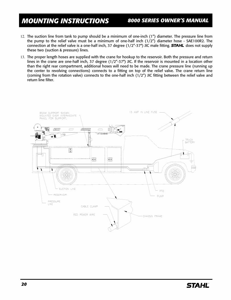
MOUNTING INSTRUCTIONS 8000 SERIES OWNER’S MANUAL
FIGURE 7
TYPICAL RESERVOIR TANK HOOK - UP
12v DC HOOK - UP
FIGURE 6
22 s
PARTS 8000 SERIES OWNER’S MANUAL
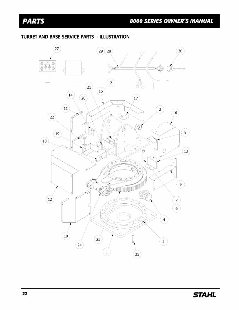
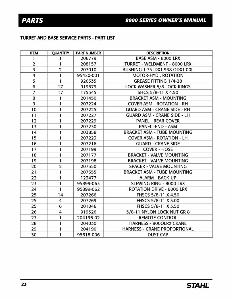
TURRET AND BASE SERVICE PARTS TURRET AND BASE SERVICE PARTS TURRET AND BASE SERVICE PARTS TURRET AND BASE SERVICE PARTS ---- ILLUSTRATION ILLUSTRATION ILLUSTRATION ILLUSTRATION
24
18
19
20
21
23
3027
2829
12
10
5
125
4
9
7
6
13
8
163
22
14
11
2
17
15
23 s
PARTS 8000 SERIES OWNER’S MANUAL
TURRET AND BASE SERVICE PARTS TURRET AND BASE SERVICE PARTS TURRET AND BASE SERVICE PARTS TURRET AND BASE SERVICE PARTS ---- PART PART PART PART LISTLISTLISTLIST
ITEMITEMITEMITEM QUANTITYQUANTITYQUANTITYQUANTITY PART NUMBERPART NUMBERPART NUMBERPART NUMBER DESCRIPTIONDESCRIPTIONDESCRIPTIONDESCRIPTION 1 1 206779 BASE ASM - 8000 LRX 2 1 208157 TURRET - WELDMENT - 8000 LRX 3 2 207010 BUSHING 1.75 IDX1.938 ODX1.00L 4 1 95420-001 MOTOR-HYD , ROTATION 5 1 926535 GREASE FITTING 1/4-28 6 17 919879 LOCK WASHER 5/8 LOCK RINGS 7 17 175545 SHCS 5/8-11 X 4.50 8 1 201450 BRACKET ASM - MOUNTING 9 1 207224 COVER ASM - ROTATION - RH 10 1 207225 GUARD ASM - CRANE SIDE - RH 11 1 207227 GUARD ASM - CRANE SIDE - LH 12 1 207229 PANEL - REAR COVER 13 1 207230 PANEL -END - ASM 14 1 203858 BRACKET ASM - TUBE MOUNTING 15 1 207223 COVER ASM - ROTATION - LH 16 1 207216 GUARD - CRANE SIDE 17 1 207199 COVER - HOSE 18 1 207177 BRACKET - VALVE MOUNTING 19 1 207198 BRACKET - VALVE MOUNTING 20 2 207350 SPACER - VALVE MOUNTING 21 1 207355 BRACKET ASM - TUBE MOUNTING 22 1 123477 ALARM - BACK-UP 23 1 95899-063 SLEWING RING - 8000 LRX 24 1 95899-062 ROTATION DRIVE - 8000 LRX 25 14 207266 FHSCS 5/8-11 X 4.50 25 4 207269 FHSCS 5/8-11 X 3.00 25 6 201046 FHSCS 5/8-11 X 3.50 26 4 919526 5/8-11 NYLON LOCK NUT GR 8 27 1 204196-02 REMOTE CONTROL 28 1 204030 HARNESS - 800OLRX CRANE 29 1 204190 HARNESS - CRANE PROPORTIONAL 30 1 95618-006 DUST CAP
24 s
PARTS 8000 SERIES OWNER’S MANUAL
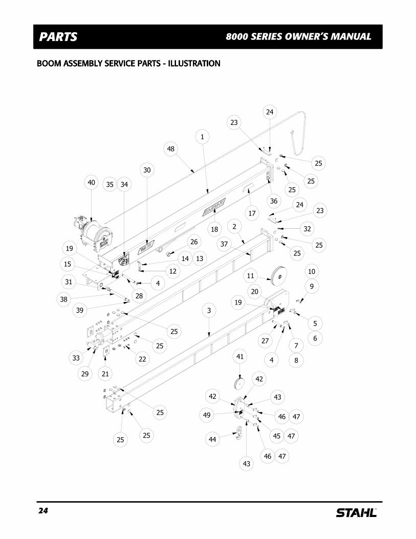
BOOM ASSEMBLY SERVICE PARTS BOOM ASSEMBLY SERVICE PARTS BOOM ASSEMBLY SERVICE PARTS BOOM ASSEMBLY SERVICE PARTS ---- ILLUSTRATION ILLUSTRATION ILLUSTRATION ILLUSTRATION
30
25
25
25
15
49
42
44
43
46 47
45 47
46 47
43
42
41
25
25
24
25
25
32
23
31
39
40
48
25
25
25
19
209
10
5
6
7
84
27
3
2
1
11
22
2129
33
19
3435
38
4
28
12
14 13
26 37
18
17
36
24
23
25 s
PARTS 8000 SERIES OWNER’S MANUAL
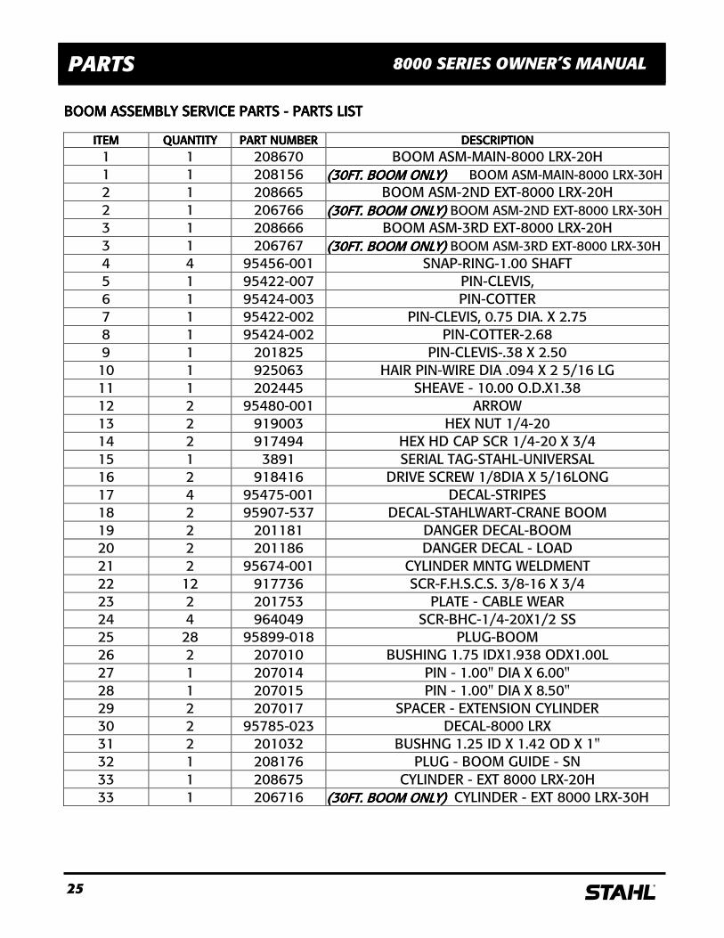
BOOM ASSEMBLY SERVICE BOOM ASSEMBLY SERVICE BOOM ASSEMBLY SERVICE BOOM ASSEMBLY SERVICE PARTS PARTS PARTS PARTS ---- PARTS LIST PARTS LIST PARTS LIST PARTS LIST
ITEMITEMITEMITEM QUANTITYQUANTITYQUANTITYQUANTITY PART NUMBERPART NUMBERPART NUMBERPART NUMBER DESCRIPTIONDESCRIPTIONDESCRIPTIONDESCRIPTION 1 1 208670 BOOM ASM-MAIN-8000 LRX-20H 1 1 208156 (30FT. BOOM ONLY)(30FT. BOOM ONLY)(30FT. BOOM ONLY)(30FT. BOOM ONLY) BOOM ASM-MAIN-8000 LRX-30H 2 1 208665 BOOM ASM-2ND EXT-8000 LRX-20H 2 1 206766 (30FT. BOOM ONLY)(30FT. BOOM ONLY)(30FT. BOOM ONLY)(30FT. BOOM ONLY) BOOM ASM-2ND EXT-8000 LRX-30H 3 1 208666 BOOM ASM-3RD EXT-8000 LRX-20H 3 1 206767 (30FT. BOOM ONLY)(30FT. BOOM ONLY)(30FT. BOOM ONLY)(30FT. BOOM ONLY) BOOM ASM-3RD EXT-8000 LRX-30H 4 4 95456-001 SNAP-RING-1.00 SHAFT 5 1 95422-007 PIN-CLEVIS, 6 1 95424-003 PIN-COTTER 7 1 95422-002 PIN-CLEVIS, 0.75 DIA. X 2.75 8 1 95424-002 PIN-COTTER-2.68 9 1 201825 PIN-CLEVIS-.38 X 2.50 10 1 925063 HAIR PIN-WIRE DIA .094 X 2 5/16 LG 11 1 202445 SHEAVE - 10.00 O.D.X1.38 12 2 95480-001 ARROW 13 2 919003 HEX NUT 1/4-20 14 2 917494 HEX HD CAP SCR 1/4-20 X 3/4 15 1 3891 SERIAL TAG-STAHL-UNIVERSAL 16 2 918416 DRIVE SCREW 1/8DIA X 5/16LONG 17 4 95475-001 DECAL-STRIPES 18 2 95907-537 DECAL-STAHLWART-CRANE BOOM 19 2 201181 DANGER DECAL-BOOM 20 2 201186 DANGER DECAL - LOAD 21 2 95674-001 CYLINDER MNTG WELDMENT 22 12 917736 SCR-F.H.S.C.S. 3/8-16 X 3/4 23 2 201753 PLATE - CABLE WEAR 24 4 964049 SCR-BHC-1/4-20X1/2 SS 25 28 95899-018 PLUG-BOOM 26 2 207010 BUSHING 1.75 IDX1.938 ODX1.00L 27 1 207014 PIN - 1.00" DIA X 6.00" 28 1 207015 PIN - 1.00" DIA X 8.50" 29 2 207017 SPACER - EXTENSION CYLINDER 30 2 95785-023 DECAL-8000 LRX 31 2 201032 BUSHNG 1.25 ID X 1.42 OD X 1" 32 1 208176 PLUG - BOOM GUIDE - SN 33 1 208675 CYLINDER - EXT 8000 LRX-20H 33 1 206716 (30FT. BOOM ONLY)(30FT. BOOM ONLY)(30FT. BOOM ONLY)(30FT. BOOM ONLY) CYLINDER - EXT 8000 LRX-30H
26 s
PARTS 8000 SERIES OWNER’S MANUAL
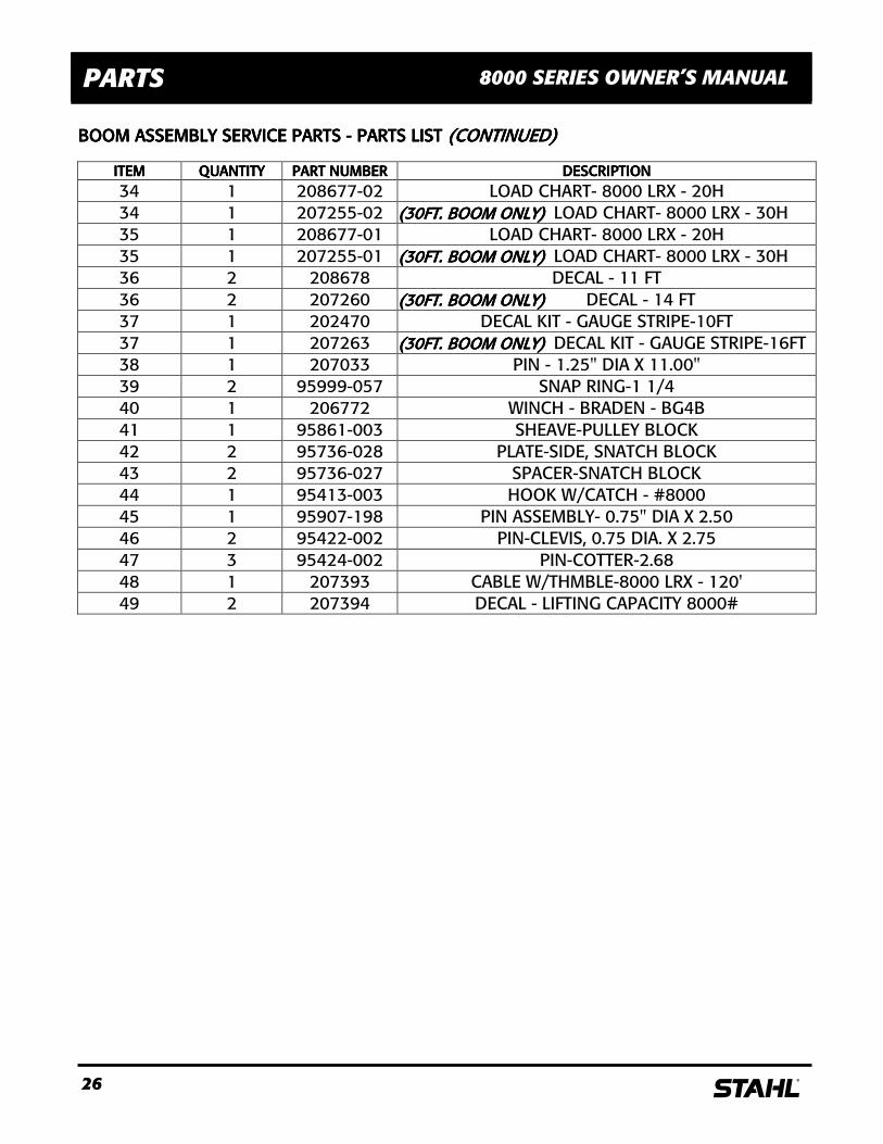
BOOM ASSEMBLY SERVICE PARTS BOOM ASSEMBLY SERVICE PARTS BOOM ASSEMBLY SERVICE PARTS BOOM ASSEMBLY SERVICE PARTS ---- PA PA PA PARTS LISTRTS LISTRTS LISTRTS LIST (CONTINUED)(CONTINUED)(CONTINUED)(CONTINUED)
ITEMITEMITEMITEM QUANTITYQUANTITYQUANTITYQUANTITY PART NUMBERPART NUMBERPART NUMBERPART NUMBER DESCRIPTIONDESCRIPTIONDESCRIPTIONDESCRIPTION 34 1 208677-02 LOAD CHART- 8000 LRX - 20H 34 1 207255-02 (30FT. BOOM ONLY)(30FT. BOOM ONLY)(30FT. BOOM ONLY)(30FT. BOOM ONLY) LOAD CHART- 8000 LRX - 30H 35 1 208677-01 LOAD CHART- 8000 LRX - 20H 35 1 207255-01 (30FT. BOOM ONLY)(30FT. BOOM ONLY)(30FT. BOOM ONLY)(30FT. BOOM ONLY) LOAD CHART- 8000 LRX - 30H 36 2 208678 DECAL - 11 FT 36 2 207260 (30FT. BOOM ONLY)(30FT. BOOM ONLY)(30FT. BOOM ONLY)(30FT. BOOM ONLY) DECAL - 14 FT 37 1 202470 DECAL KIT - GAUGE STRIPE-10FT 37 1 207263 (30FT. BOOM ONLY)(30FT. BOOM ONLY)(30FT. BOOM ONLY)(30FT. BOOM ONLY) DECAL KIT - GAUGE STRIPE-16FT 38 1 207033 PIN - 1.25" DIA X 11.00" 39 2 95999-057 SNAP RING-1 1/4 40 1 206772 WINCH - BRADEN - BG4B 41 1 95861-003 SHEAVE-PULLEY BLOCK 42 2 95736-028 PLATE-SIDE, SNATCH BLOCK 43 2 95736-027 SPACER-SNATCH BLOCK 44 1 95413-003 HOOK W/CATCH - #8000 45 1 95907-198 PIN ASSEMBLY- 0.75" DIA X 2.50 46 2 95422-002 PIN-CLEVIS, 0.75 DIA. X 2.75 47 3 95424-002 PIN-COTTER-2.68 48 1 207393 CABLE W/THMBLE-8000 LRX - 120' 49 2 207394 DECAL - LIFTING CAPACITY 8000#
27 s
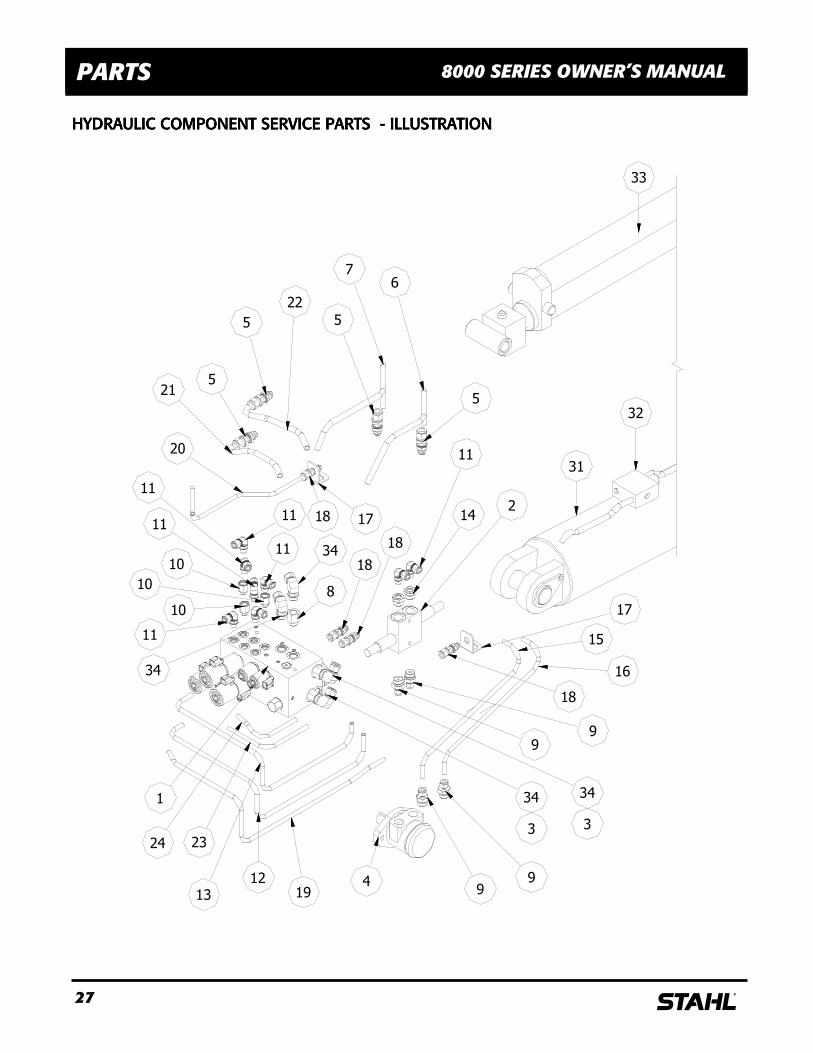
PARTS 8000 SERIES OWNER’S MANUAL
HYDRAULIC COMPONENT SERVICE PARTS HYDRAULIC COMPONENT SERVICE PARTS HYDRAULIC COMPONENT SERVICE PARTS HYDRAULIC COMPONENT SERVICE PARTS ---- ILLUSTRATION ILLUSTRATION ILLUSTRATION ILLUSTRATION
13
24 23
12
19
1
34
10
11
10
10
11
34
8
11
11
11
34
3
15
18
18
34
3
99
16
2
9
9
18
17
14
1120
18 17
22
215
5
5
6
5
7
32
33
31
4
28 s
PARTS 8000 SERIES OWNER’S MANUAL
HYDRAULIC COMPONENT SERVICE PARTS HYDRAULIC COMPONENT SERVICE PARTS HYDRAULIC COMPONENT SERVICE PARTS HYDRAULIC COMPONENT SERVICE PARTS ---- PARTS LI PARTS LI PARTS LI PARTS LISTSTSTST
ITEMITEMITEMITEM QUANTITYQUANTITYQUANTITYQUANTITY PART NUMBERPART NUMBERPART NUMBERPART NUMBER DESCRIPTIONDESCRIPTIONDESCRIPTIONDESCRIPTION 1 1 203122 VAVLE - COMBO - 4 FUNCTION 2 1 95736-039 CROSS RELIEF VAVLE 3 2 203871 ADAPTER -10MOR X -8FOR 4 1 95420-001 MOTOR-HYD , ROTATION 5 4 95488-022 BULKHEAD UNION-1/2-TUBE TO 1/2-JIC MALE 6 1 207200 TUBE - PRESSURE 7 1 207201 TUBE - RETURN 8 1 203876 ADAPTER -8MOR X -8FOR 9 4 95488-011 CONNECTOR - 10 MOR X -6 TUBE FLAIRLESS 10 3 203870 ADAPTER -6MOR X -6FOR 11 8 95488-006 ELBOW -6 MOR X -6 TUBE SWAGELOK 12 1 207301 TUBE - VALVE TO ROTAION RELIEF 13 1 207303 TUBE - VALVE TO ROTATION RELIE 14 2 203873 ADAPTER -10MOR X -6FOR 15 1 207307 TUBE-ROTATION RELIEF TO MOTOR 16 1 207320 TUBE-ROTATION RELIEF TO MOTOR 17 2 201487 BRACKET - TUBE MTG 18 4 95488-005 BULKHEAD UNION-3/8 TUBE TO 3/8-JIC 19 1 207324 TUBE - BOOM LIFT 20 1 207327 TUBE - BOOM LIFT 21 1 207331 TUBE - WINCH 22 1 207333 TUBE - WINCH 23 1 207341 TUBE - EXTENSION 24 1 207344 TUBE - EXTENSION 25 2 203880 HOSE - 21" (EXTEND) 26 2 203881 HOSE - 21" (LIFT) 27 1 203884 HOSE - 21" (WINCH) 28 1 203885 HOSE - 24" (WINCH) 29 1 203892 HOSE - 34" (RETURN) 30 1 203893 HOSE - 36" (PRESSURE) 31 1 208162 CYLINDER - LIFT 8000 LRX 32 1 95723-003 PRESSURE SWITCH - 3000PSI 33 1 208675 CYLINDER - EXT 8000 LRX-20H 33 1 206716 (30FT. BOOM ONLY)(30FT. BOOM ONLY)(30FT. BOOM ONLY)(30FT. BOOM ONLY) CYLINDER - EXT 8000 LRX-30H 34 4 203872 ELBOW - SWGLOK -8TUBE X -8MOR
29 s
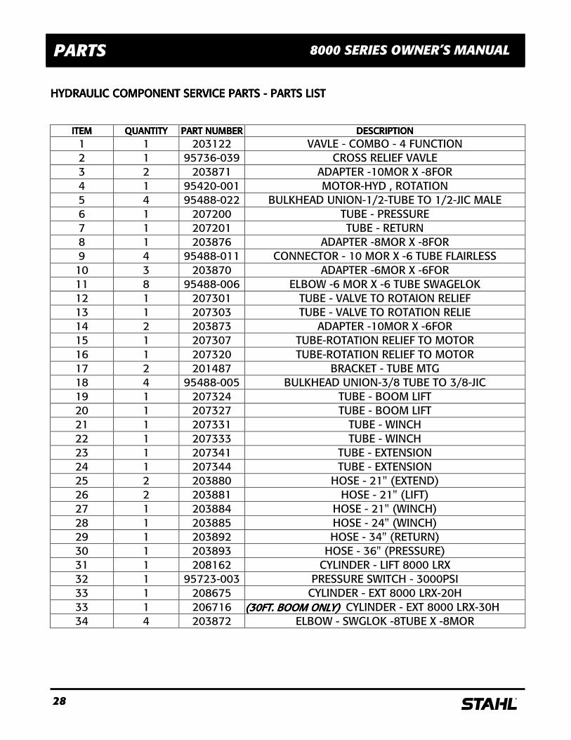
PARTS 8000 SERIES OWNER’S MANUAL
ANTI TWOANTI TWOANTI TWOANTI TWO----BLOCK PARTSBLOCK PARTSBLOCK PARTSBLOCK PARTS
TEMTEMTEMTEM QUANTITYQUANTITYQUANTITYQUANTITY PART NUMBERPART NUMBERPART NUMBERPART NUMBER DESCRIPTIONDESCRIPTIONDESCRIPTIONDESCRIPTION
1 4 95493-005 BUSHING-SHORTY 2 1 95493-013 BRACKET-CORD REEL 3 2 917806 TRUSS HD M.S. 1/4-20 X 1/2 4 6 962110 HEX WASHER HD-SELF TAPPING 5 1 201524 COVER - SWITCH MOUNTING 6 1 95493-003 SWITCH - HOLDER 7 1 95493-002 SWITCH-WATERPROOF 8 1 95493-004 STRAIN RELIEF 9 3 95493-006 BRACKET BUSHING-MAIN 10 1 95493-011 BRACKET BUSHING-HYD 11 1 207272 GUIDE ASM - CABLE 12 1 95467-001 CORD REEL
11
4
5
7
681
10
4
4
1
9
4
1
91
4
9
2
12
3
30 s
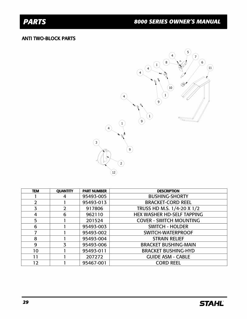
PARTS 8000 SERIES OWNER’S MANUAL
HYDRAULIC RESERVOIR TANK HYDRAULIC RESERVOIR TANK HYDRAULIC RESERVOIR TANK HYDRAULIC RESERVOIR TANK ---- ILLUSTRATIONS ILLUSTRATIONS ILLUSTRATIONS ILLUSTRATIONS
31 s
PARTS 8000 SERIES OWNER’S MANUAL
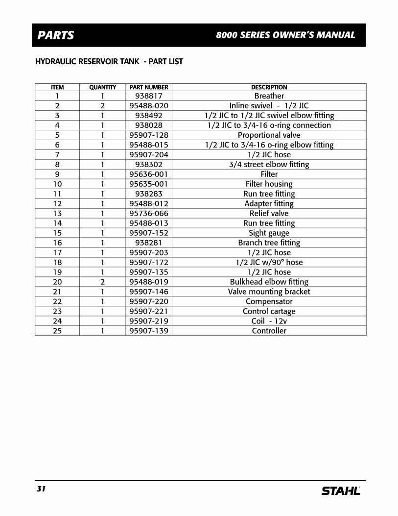
HYDRAULIC RESERVOIR TANK HYDRAULIC RESERVOIR TANK HYDRAULIC RESERVOIR TANK HYDRAULIC RESERVOIR TANK ---- PART LIST PART LIST PART LIST PART LIST
ITEMITEMITEMITEM QUANTITYQUANTITYQUANTITYQUANTITY PART NUMBERPART NUMBERPART NUMBERPART NUMBER DESCRIPTIONDESCRIPTIONDESCRIPTIONDESCRIPTION
1 1 938817 Breather 2 2 95488-020 Inline swivel - 1/2 JIC 3 1 938492 1/2 JIC to 1/2 JIC swivel elbow fitting 4 1 938028 1/2 JIC to 3/4-16 o-ring connection 5 1 95907-128 Proportional valve 6 1 95488-015 1/2 JIC to 3/4-16 o-ring elbow fitting 7 1 95907-204 1/2 JIC hose 8 1 938302 3/4 street elbow fitting 9 1 95636-001 Filter 10 1 95635-001 Filter housing 11 1 938283 Run tree fitting 12 1 95488-012 Adapter fitting 13 1 95736-066 Relief valve 14 1 95488-013 Run tree fitting 15 1 95907-152 Sight gauge 16 1 938281 Branch tree fitting 17 1 95907-203 1/2 JIC hose 18 1 95907-172 1/2 JIC w/90° hose 19 1 95907-135 1/2 JIC hose 20 2 95488-019 Bulkhead elbow fitting 21 1 95907-146 Valve mounting bracket 22 1 95907-220 Compensator 23 1 95907-221 Control cartage 24 1 95907-219 Coil - 12v 25 1 95907-139 Controller
32 s
PARTS 8000 SERIES OWNER’S MANUAL
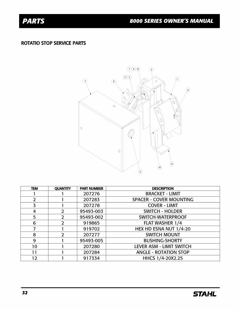
ROTATIO STOP SERVICE PARTSROTATIO STOP SERVICE PARTSROTATIO STOP SERVICE PARTSROTATIO STOP SERVICE PARTS
TEMTEMTEMTEM QUANTITYQUANTITYQUANTITYQUANTITY PART NUMBERPART NUMBERPART NUMBERPART NUMBER DESCRIPTIONDESCRIPTIONDESCRIPTIONDESCRIPTION
1 1 207276 BRACKET - LIMIT 2 1 207283 SPACER - COVER MOUNTING 3 1 207278 COVER - LIMIT 4 2 95493-003 SWITCH - HOLDER 5 2 95493-002 SWITCH-WATERPROOF 6 2 919865 FLAT WASHER 1/4 7 1 919702 HEX HD ESNA NUT 1/4-20 8 2 207277 SWITCH MOUNT 9 1 95493-005 BUSHING-SHORTY 10 1 207280 LEVER ASM - LIMIT SWITCH 11 1 207284 ANGLE - ROTATION STOP 12 1 917334 HHCS 1/4-20X2.25
3 8
45
2
1
8
9
11
10
1267
33 s
SCHEMATICS 8000 SERIES OWNER’S MANUAL
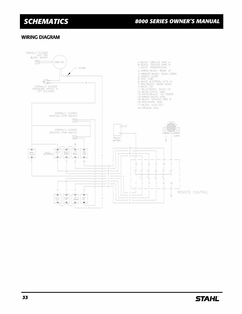
WIRING DIAGRAMWIRING DIAGRAMWIRING DIAGRAMWIRING DIAGRAM
34 s
SCHEMATICS 8000 SERIES OWNER’S MANUAL
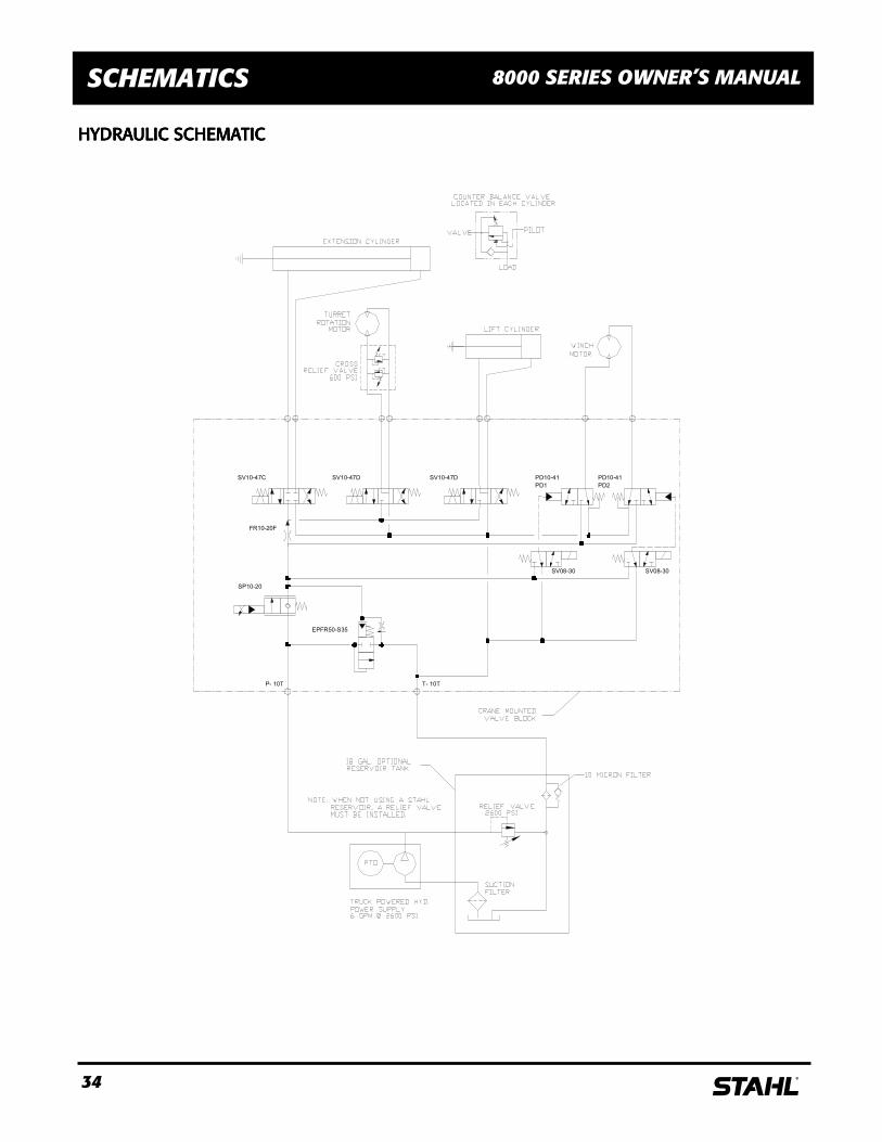
HYDRHYDRHYDRHYDRAULIC SCHEMATICAULIC SCHEMATICAULIC SCHEMATICAULIC SCHEMATIC
P- 10T T- 10T
SV10-47D SV10-47D
SP10-20
EPFR50-S35
FR10-20F
SV08-30 SV08-30
SV10-47C
PD1
PD10-41
PD2
PD10-41
35 s
ONE – YEAR LIMITED WARRANTY
COVERED PRODUCTS:COVERED PRODUCTS:COVERED PRODUCTS:COVERED PRODUCTS:
� s Crane Crane Crane Crane –––– One (1) year from the date of purchase by the original owner of record for s parts including the structural integrity of the crane boom assembly, turret assembly, and base plate weldment. Product(s) not made of galvaneal steel are warranted to the original owner of record for 180 days from the date of purchase.
� Should the warranted product rust through s will cover labor and materials to replace and/or repair defective materials and/or install new materials (solely at the discretion of s)
� The foregoing collectively constitutes the “Warranty”. ELIGIBILITYELIGIBILITYELIGIBILITYELIGIBILITY.
� This Warranty shall only apply to products listed herein and initially purchased after June 1, 1995 � Product(s) warranted must be properly maintained and serviced under the guidelines recommended in the owner’s
manual. The original owner must complete and submit the warranty registration card within thirty (30) days of purchase.
� This Warranty applies only when an authorized s up fitter properly installs the product, and it is used for the purpose for which it was designed.
� This Warranty is not transferable. EXCLUSIONSEXCLUSIONSEXCLUSIONSEXCLUSIONS
� This Warranty applies to s Cranes only and excludes all items supplied by distributors or mounting stations including, but not limited to finish paint, lettering, installation, wiring, optional parts, modifications and the like.
� Product(s) that have been misused, abused, altered, or intentionally damaged. SPECIFIC “NO RUST, NO BUST” WARRANTY EXCLUSIONSSPECIFIC “NO RUST, NO BUST” WARRANTY EXCLUSIONSSPECIFIC “NO RUST, NO BUST” WARRANTY EXCLUSIONSSPECIFIC “NO RUST, NO BUST” WARRANTY EXCLUSIONS
� Product(s) must have perforation in the metal. Rust in the paint or surface rust is not considered rust through. � Product(s) purchased in prime paint condition. � Product(s) purchased and used outside the United States and Canada. � Product(s) used to carry corrosive materials. � s shall not be liable to the original owner/user or any third party for any direct or indirect, incidental or
consequential damages including, but not limited to, transportation costs, lost profits, and loss of income, as a result of a vehicle being out of service.
WARRANTY CLAIMS PROCEDUREWARRANTY CLAIMS PROCEDUREWARRANTY CLAIMS PROCEDUREWARRANTY CLAIMS PROCEDURE
� Claims may be handled by contacting your nearest authorized s distributor. All claims are to be filed in writing and will be administered through a s distributor. All repairs must be authorized by s prior to any work being performed and must be done by an authorized s distributor or by a person or company pre-approved by s in writing.
� s reserves the right to inspect products returned by the original owner under this Warranty to determine whether the product is covered. Inspection shall, at s’s option, be performed at the factory, or at such other reasonable place as may be designated by s, and in such event freight for returning products shall be paid by the original owner. s also reserves the right to require dated proof of purchase from the original owner. Unauthorized repair or replacement prior to inspection or repair or replacement not in accordance with s recommendations and procedures may void the Warranty.
. DISCLAIMER OF IMPLIED WARRANTIES; LIMITATIONS OF DISCLAIMER OF IMPLIED WARRANTIES; LIMITATIONS OF DISCLAIMER OF IMPLIED WARRANTIES; LIMITATIONS OF DISCLAIMER OF IMPLIED WARRANTIES; LIMITATIONS OF REMEDIES:REMEDIES:REMEDIES:REMEDIES: THERE ARE NO OTHER WARRANTIES, EXPRESSED OR IMPLIED, GIVEN BYTHERE ARE NO OTHER WARRANTIES, EXPRESSED OR IMPLIED, GIVEN BYTHERE ARE NO OTHER WARRANTIES, EXPRESSED OR IMPLIED, GIVEN BYTHERE ARE NO OTHER WARRANTIES, EXPRESSED OR IMPLIED, GIVEN BY s FOR THIS PRODUCT. IMPLIED WARRANTIES OF FOR THIS PRODUCT. IMPLIED WARRANTIES OF FOR THIS PRODUCT. IMPLIED WARRANTIES OF FOR THIS PRODUCT. IMPLIED WARRANTIES OF MERCHANTABILITY AND FITNESS FOR A PARTICULAR PURPOSE ARE SPECIFICALLY DISCLAIMED. THE PURCHASER’S REMEDIES MERCHANTABILITY AND FITNESS FOR A PARTICULAR PURPOSE ARE SPECIFICALLY DISCLAIMED. THE PURCHASER’S REMEDIES MERCHANTABILITY AND FITNESS FOR A PARTICULAR PURPOSE ARE SPECIFICALLY DISCLAIMED. THE PURCHASER’S REMEDIES MERCHANTABILITY AND FITNESS FOR A PARTICULAR PURPOSE ARE SPECIFICALLY DISCLAIMED. THE PURCHASER’S REMEDIES FOR LOSS, DAMAGE, OR EXPENSE RESULTFOR LOSS, DAMAGE, OR EXPENSE RESULTFOR LOSS, DAMAGE, OR EXPENSE RESULTFOR LOSS, DAMAGE, OR EXPENSE RESULTING FROM THE USE OR MISUSE OF THIS PRODUCT ARE LIMITED TO THOSE ING FROM THE USE OR MISUSE OF THIS PRODUCT ARE LIMITED TO THOSE ING FROM THE USE OR MISUSE OF THIS PRODUCT ARE LIMITED TO THOSE ING FROM THE USE OR MISUSE OF THIS PRODUCT ARE LIMITED TO THOSE EXPRESSED IN THIS LIMITED WARRANTY.EXPRESSED IN THIS LIMITED WARRANTY.EXPRESSED IN THIS LIMITED WARRANTY.EXPRESSED IN THIS LIMITED WARRANTY. THIS LIMITED WARRANTY GIVES PURCHASER SPECIFIC LEGAL RIGHTS, AND PURCHASER MAY ALSO HAVE OTHER RIGHTS, THIS LIMITED WARRANTY GIVES PURCHASER SPECIFIC LEGAL RIGHTS, AND PURCHASER MAY ALSO HAVE OTHER RIGHTS, THIS LIMITED WARRANTY GIVES PURCHASER SPECIFIC LEGAL RIGHTS, AND PURCHASER MAY ALSO HAVE OTHER RIGHTS, THIS LIMITED WARRANTY GIVES PURCHASER SPECIFIC LEGAL RIGHTS, AND PURCHASER MAY ALSO HAVE OTHER RIGHTS, WHICH VARY FROM STATE TO STATE. SOME STATES DO NOT WHICH VARY FROM STATE TO STATE. SOME STATES DO NOT WHICH VARY FROM STATE TO STATE. SOME STATES DO NOT WHICH VARY FROM STATE TO STATE. SOME STATES DO NOT ALLOW DISCLAIMERS OF OR LIMITATIONS ON IMPLIED ALLOW DISCLAIMERS OF OR LIMITATIONS ON IMPLIED ALLOW DISCLAIMERS OF OR LIMITATIONS ON IMPLIED ALLOW DISCLAIMERS OF OR LIMITATIONS ON IMPLIED WARRANTIES OR THE EXCLUSION OR LIMITATIONS OF INCIDENTAL OR CONSEQUENTIAL DAMAGES, SO THE ABOVE WARRANTIES OR THE EXCLUSION OR LIMITATIONS OF INCIDENTAL OR CONSEQUENTIAL DAMAGES, SO THE ABOVE WARRANTIES OR THE EXCLUSION OR LIMITATIONS OF INCIDENTAL OR CONSEQUENTIAL DAMAGES, SO THE ABOVE WARRANTIES OR THE EXCLUSION OR LIMITATIONS OF INCIDENTAL OR CONSEQUENTIAL DAMAGES, SO THE ABOVE DISCLAIMER AND LIMITATION MAY NOT APPLY TO PURCHASERDISCLAIMER AND LIMITATION MAY NOT APPLY TO PURCHASERDISCLAIMER AND LIMITATION MAY NOT APPLY TO PURCHASERDISCLAIMER AND LIMITATION MAY NOT APPLY TO PURCHASER