8000 base unit user manual
DESCRIPTION
Tài liệu hướng dẫn sử dụng máy đo quang JDSU MTS 8000TRANSCRIPT

8000 Base UnitPortable, modular platform designed for the construction, validation and maintenance of optical fiber networks
User Manual


8000 Base UnitPortable, modular platform designed for the construction, validation and maintenance of optical fiber networks
User Manual


Notice Every effort was made to ensure that the information in this document was accurate at the time of printing. However, information is subject to change without notice, and JDSU reserves the right to provide an addendum to this document with information not available at the time that this document was created.
Copyright © Copyright 2006 JDSU, LLC. All rights reserved. JDSU, Enabling Broadband and Optical Innovation, and its logo are trademarks of JDSU, LLC. All other trademarks and registered trademarks are the property of their respective owners. No part of this guide may be reproduced or transmitted electronically or otherwise without written permission of the publisher.
Trademarks JDSU is a trademark of JDSU in the United States and other countries.
Microsoft, Windows, Windows CE, Windows NT, MS-DOS, Excel, Word and Microsoft Internet Explorer are either trademarks or registered trade-marks of Microsoft Corporation in the United States and/or other coun-tries.
Specifications, terms, and conditions are subject to change without notice. All trademarks and registered trademarks are the property of their respective companies.
Manual This guide is a product of JDSU's Technical Information Development Department. This manual gives you the main information to install, start and use the 8000 Base Unit.
WEEE DirectiveCompliance
JDSU has established processes in compliance with the Waste Electrical and Electronic Equipment (WEEE) Directive, 2002/96/EC.
This product should not be disposed of as unsorted municipal waste and should be collected separately and disposed of according to your national regulations. In the European Union, all equipment purchased from JDSU after 2005-08-13 can be returned for disposal at the end of its useful life. JDSU will ensure that all waste equipment returned is reused, recycled, or disposed of in an environmentally friendly manner, and in compliance with all applicable national and international waste legislation.
It is the responsibility of the equipment owner to return the equipment to JDSU for appropriate disposal. If the equipment was imported by a reseller whose name or logo is marked on the equipment, then the owner should return the equipment directly to the reseller.
User Manual 780000002/12 v

Instructions for returning waste equipment to JDSU can be found in the Environmental section of JDSU’s web site at www.jdsu.com. If you have questions concerning disposal of your equipment, contact JDSU’s WEEE Program Management team at [email protected].
vi User Manual 780000002/12
Table of Contents
About this guide xvPurpose and scope . . . . . . . . . . . . . . . . . . . . . . . . . . . . . . . . . . . . .xviAssumptions . . . . . . . . . . . . . . . . . . . . . . . . . . . . . . . . . . . . . . . . xviTechnical assistance . . . . . . . . . . . . . . . . . . . . . . . . . . . . . . . . . xviRecycling Information . . . . . . . . . . . . . . . . . . . . . . . . . . . . . . . xviiConventions . . . . . . . . . . . . . . . . . . . . . . . . . . . . . . . . . . . . . . . xvii
Chapter 1 Introducing the Platform 8000 1Terminology used in this manual . . . . . . . . . . . . . . . . . . . . . . . . . . . 2Laser safety . . . . . . . . . . . . . . . . . . . . . . . . . . . . . . . . . . . . . . . . . . 2
Laser classes . . . . . . . . . . . . . . . . . . . . . . . . . . . . . . . . . . . . . . . 3Warning labels for the laser classes . . . . . . . . . . . . . . . . . . . . . 3
AC/DC and battery important safety instructions . . . . . . . . . . . 4Architecture . . . . . . . . . . . . . . . . . . . . . . . . . . . . . . . . . . . . . . . . . 5User interface . . . . . . . . . . . . . . . . . . . . . . . . . . . . . . . . . . . . . . . . 6Technology . . . . . . . . . . . . . . . . . . . . . . . . . . . . . . . . . . . . . . . . . . 6Mechanical strength . . . . . . . . . . . . . . . . . . . . . . . . . . . . . . . . . . . 6Software . . . . . . . . . . . . . . . . . . . . . . . . . . . . . . . . . . . . . . . . . . . . 7Measurements . . . . . . . . . . . . . . . . . . . . . . . . . . . . . . . . . . . . . . . 7
Chapter 2 Starting up 9Unpacking the instrument . . . . . . . . . . . . . . . . . . . . . . . . . . . . . . . . 10
User Manual 780000002/12 vii
Table of Contents
Assembling the component parts of the Platform 8000 . . . . . . 10Fitting and removing a module or receptacle . . . . . . . . . . . . . . 10
Key principles . . . . . . . . . . . . . . . . . . . . . . . . . . . . . . . . . . . . . .11Required tools . . . . . . . . . . . . . . . . . . . . . . . . . . . . . . . . . . . . . .11Assembling the instrument . . . . . . . . . . . . . . . . . . . . . . . . . . . .11
Disconnecting the Module . . . . . . . . . . . . . . . . . . . . . . . . . . . . 16Required tools . . . . . . . . . . . . . . . . . . . . . . . . . . . . . . . . . . . . . 16Disassembling the instrument . . . . . . . . . . . . . . . . . . . . . . . . . 16
Fitting and removing a floppy drive or CD-Rom drive . . . . . . . 17Installing and removing a plug-in unit in a receptacle . . . . . . . 18
Choosing the position of the instrument on the work surface 19Fitting the carrying handle or strap . . . . . . . . . . . . . . . . . . . . . . 20
Battery management . . . . . . . . . . . . . . . . . . . . . . . . . . . . . . . . . 20Battery Operating Limit . . . . . . . . . . . . . . . . . . . . . . . . . . . . . . 20Charging the batteries . . . . . . . . . . . . . . . . . . . . . . . . . . . . . . . 21
Connecting the mains adapter . . . . . . . . . . . . . . . . . . . . . . . . . 21Charging . . . . . . . . . . . . . . . . . . . . . . . . . . . . . . . . . . . . . . . . . 21Battery charging time . . . . . . . . . . . . . . . . . . . . . . . . . . . . . . . . 21Battery endurance . . . . . . . . . . . . . . . . . . . . . . . . . . . . . . . . . . 21Batteries thresholds . . . . . . . . . . . . . . . . . . . . . . . . . . . . . . . . 22Charge and On indicators . . . . . . . . . . . . . . . . . . . . . . . . . . . . 23Battery charge level display . . . . . . . . . . . . . . . . . . . . . . . . . . . 23
Access to the batteries . . . . . . . . . . . . . . . . . . . . . . . . . . . . . . . 24Safety recommendations . . . . . . . . . . . . . . . . . . . . . . . . . . . . . 25
Switching the Platform 8000 on and off . . . . . . . . . . . . . . . . . . 25Switching on the Platform 8000 . . . . . . . . . . . . . . . . . . . . . . . . 25Switching off the Platform 8000 . . . . . . . . . . . . . . . . . . . . . . . . 26Reset . . . . . . . . . . . . . . . . . . . . . . . . . . . . . . . . . . . . . . . . . . . . 27
Presentation page of the Platform 8000 . . . . . . . . . . . . . . . . . . 27Troubleshooting . . . . . . . . . . . . . . . . . . . . . . . . . . . . . . . . . . . . . 28
Chapter 3 Controls of the Platform 8000 29Control interface . . . . . . . . . . . . . . . . . . . . . . . . . . . . . . . . . . . . . . . 30
TFT display screen . . . . . . . . . . . . . . . . . . . . . . . . . . . . . . . . . . 31Control buttons . . . . . . . . . . . . . . . . . . . . . . . . . . . . . . . . . . . . . 31Indicators . . . . . . . . . . . . . . . . . . . . . . . . . . . . . . . . . . . . . . . . . 33Direction keys . . . . . . . . . . . . . . . . . . . . . . . . . . . . . . . . . . . . . . 33
Using an external keyboard, mouse and screen touch (options) 33
Virtual control buttons bar . . . . . . . . . . . . . . . . . . . . . . . . . . . . 34Equivalence between external keyboard and Platform 8000 . . 34
User Manual 780000002/12 viii

Table of Contents
Editing text using the external keyboard . . . . . . . . . . . . . . . . . 35Editing . . . . . . . . . . . . . . . . . . . . . . . . . . . . . . . . . . . . . . . . . . . . . 35
Numeric Keypad . . . . . . . . . . . . . . . . . . . . . . . . . . . . . . . . . . . . 38Accessing the Platform 8000 from a PC . . . . . . . . . . . . . . . . . . 39
Connecting the Platform 8000 to a PC . . . . . . . . . . . . . . . . . . . 39Direct connection . . . . . . . . . . . . . . . . . . . . . . . . . . . . . . . . . . 39Connection via a local network . . . . . . . . . . . . . . . . . . . . . . . . 40
Transfer of the interface of the Platform 8000 on to a PC . . . . 41Accessing the hard disk of the Platform 8000 via a PC . . . . . . 41
Creating a shortcut toward the Platform 8000 harddisk . . . . . . 42Connectors . . . . . . . . . . . . . . . . . . . . . . . . . . . . . . . . . . . . . . . . . 44
Right-hand side . . . . . . . . . . . . . . . . . . . . . . . . . . . . . . . . . . . . 44Rear panel . . . . . . . . . . . . . . . . . . . . . . . . . . . . . . . . . . . . . . . . 44
Floppy disk or CD-ROM drive (option) . . . . . . . . . . . . . . . . . . . 46Serial port (RS 232 - not used) . . . . . . . . . . . . . . . . . . . . . . . . . . 46SVGA connector . . . . . . . . . . . . . . . . . . . . . . . . . . . . . . . . . . . . . 47CompactFlash port . . . . . . . . . . . . . . . . . . . . . . . . . . . . . . . . . . . 47
Chapter 4 System set-up 49Principle of the set-up menus . . . . . . . . . . . . . . . . . . . . . . . . . . 50Configuring the instrument . . . . . . . . . . . . . . . . . . . . . . . . . . . . 50
Validating several simultaneous functions . . . . . . . . . . . . . . . . 53Help . . . . . . . . . . . . . . . . . . . . . . . . . . . . . . . . . . . . . . . . . . . . . 53
Configuring the unit . . . . . . . . . . . . . . . . . . . . . . . . . . . . . . . . . . 53Factory Default Configuration . . . . . . . . . . . . . . . . . . . . . . . . . 54Screen . . . . . . . . . . . . . . . . . . . . . . . . . . . . . . . . . . . . . . . . . . . 55Country . . . . . . . . . . . . . . . . . . . . . . . . . . . . . . . . . . . . . . . . . . . 57I/O Interface . . . . . . . . . . . . . . . . . . . . . . . . . . . . . . . . . . . . . . . 58Utilities . . . . . . . . . . . . . . . . . . . . . . . . . . . . . . . . . . . . . . . . . . . 61Printer . . . . . . . . . . . . . . . . . . . . . . . . . . . . . . . . . . . . . . . . . . . . 62
Files (Formatted) . . . . . . . . . . . . . . . . . . . . . . . . . . . . . . . . . . . 63Files (Screen) . . . . . . . . . . . . . . . . . . . . . . . . . . . . . . . . . . . . . 64
Standalone results . . . . . . . . . . . . . . . . . . . . . . . . . . . . . . . . . . . 65Expert Tools . . . . . . . . . . . . . . . . . . . . . . . . . . . . . . . . . . . . . . . . 65
Software Upgrade . . . . . . . . . . . . . . . . . . . . . . . . . . . . . . . . . . 65Remote Display . . . . . . . . . . . . . . . . . . . . . . . . . . . . . . . . . . . . 65
User Manual 780000002/12 ix

Table of Contents
Media utilities . . . . . . . . . . . . . . . . . . . . . . . . . . . . . . . . . . . . . . 65Formating a USB memory stick . . . . . . . . . . . . . . . . . . . . . . . . 65Formatting a CompactFlash card . . . . . . . . . . . . . . . . . . . . . . 66Formatting a CD . . . . . . . . . . . . . . . . . . . . . . . . . . . . . . . . . . . 66Removing the USB memory stick . . . . . . . . . . . . . . . . . . . . . . 66Erase disk . . . . . . . . . . . . . . . . . . . . . . . . . . . . . . . . . . . . . . . . 67
Locking the Platform 8000 . . . . . . . . . . . . . . . . . . . . . . . . . . . . 67Desktop Applications . . . . . . . . . . . . . . . . . . . . . . . . . . . . . . . . . 68
Chapter 5 LTS (Loss Test Set) 69The principle of optical power and attenuation measurements . 70
Power measurements . . . . . . . . . . . . . . . . . . . . . . . . . . . . . . . 70Attenuation measurements (optical link loss) . . . . . . . . . . . . . . 70
Connection to the power meter and the source . . . . . . . . . . . . 71Configuring the LTS . . . . . . . . . . . . . . . . . . . . . . . . . . . . . . . . . . 72
Configuring the measurement parameters of the power meter 72Configuring the alarm parameters of the power meter . . . . . . . 73Configuring and displaying the parameters of the source . . . . 74
Display of results and commands . . . . . . . . . . . . . . . . . . . . . . . 75Result of the measurement in progress . . . . . . . . . . . . . . . . . . 75Table of results . . . . . . . . . . . . . . . . . . . . . . . . . . . . . . . . . . . . . 76Commands of the power meter parameters . . . . . . . . . . . . . . . 76
Making a measurement . . . . . . . . . . . . . . . . . . . . . . . . . . . . . . . 77Power measurement . . . . . . . . . . . . . . . . . . . . . . . . . . . . . . . . 77Optical link loss . . . . . . . . . . . . . . . . . . . . . . . . . . . . . . . . . . . . 78
Setting the zero value of the power meter . . . . . . . . . . . . . . . . 78Carrying out the reference measurement . . . . . . . . . . . . . . . . 78Measurements on the fiber under test . . . . . . . . . . . . . . . . . . . 78
Performing an ORL Manual measurement with the Platform 8000 79
Establishing a reference for an ORL manual measurement . . 79ORL Emitted power . . . . . . . . . . . . . . . . . . . . . . . . . . . . . . . . . 79ORL Zero adjustment . . . . . . . . . . . . . . . . . . . . . . . . . . . . . . . 81
Measurement acquisition . . . . . . . . . . . . . . . . . . . . . . . . . . . . . 82Storing and reloading LTS results . . . . . . . . . . . . . . . . . . . . . . . 83
File Setup . . . . . . . . . . . . . . . . . . . . . . . . . . . . . . . . . . . . . . . . . 83Storing results . . . . . . . . . . . . . . . . . . . . . . . . . . . . . . . . . . . . . 83Loading results . . . . . . . . . . . . . . . . . . . . . . . . . . . . . . . . . . . . . 84
User Manual 780000002/12 x

Table of Contents
Chapter 6 VFL, Talkset and Data transfer 85VFL and Talkset connectors . . . . . . . . . . . . . . . . . . . . . . . . . . . . . . 86
Talkset connectors . . . . . . . . . . . . . . . . . . . . . . . . . . . . . . . . . . 86VFL connector . . . . . . . . . . . . . . . . . . . . . . . . . . . . . . . . . . . . . 86
Visible source function (VFL) . . . . . . . . . . . . . . . . . . . . . . . . . . 86«Talkset» optical telephone function . . . . . . . . . . . . . . . . . . . . 87«Data», the data transfer function . . . . . . . . . . . . . . . . . . . . . . . 88VNC - Remote screen . . . . . . . . . . . . . . . . . . . . . . . . . . . . . . . . . 90
Chapter 7 Scope 93Scope feature . . . . . . . . . . . . . . . . . . . . . . . . . . . . . . . . . . . . . . . . . . 94Scope connection . . . . . . . . . . . . . . . . . . . . . . . . . . . . . . . . . . . . 94Result display . . . . . . . . . . . . . . . . . . . . . . . . . . . . . . . . . . . . . . . 95
Camera mode . . . . . . . . . . . . . . . . . . . . . . . . . . . . . . . . . . . . . 95Freeze mode . . . . . . . . . . . . . . . . . . . . . . . . . . . . . . . . . . . . . . 96
File toolbar . . . . . . . . . . . . . . . . . . . . . . . . . . . . . . . . . . . . . . . . . 98Saving a picture . . . . . . . . . . . . . . . . . . . . . . . . . . . . . . . . . . . . 98Loading a picture . . . . . . . . . . . . . . . . . . . . . . . . . . . . . . . . . . . 98
Mosaic Mode . . . . . . . . . . . . . . . . . . . . . . . . . . . . . . . . . . . . . . . . 99File toolbar . . . . . . . . . . . . . . . . . . . . . . . . . . . . . . . . . . . . . . . 101
Chapter 8 Desktop applications 103PDF viewer . . . . . . . . . . . . . . . . . . . . . . . . . . . . . . . . . . . . . . . . . . . 104
Opening a PDF document . . . . . . . . . . . . . . . . . . . . . . . . . . . 104Interacting with a PDF document . . . . . . . . . . . . . . . . . . . . . . 104
Web browser . . . . . . . . . . . . . . . . . . . . . . . . . . . . . . . . . . . . . . . 105Starting the web browser . . . . . . . . . . . . . . . . . . . . . . . . . . . . 105Setting the internet connection . . . . . . . . . . . . . . . . . . . . . . . . 105Platform 8000 Keys . . . . . . . . . . . . . . . . . . . . . . . . . . . . . . . . 106Virtual keyboard . . . . . . . . . . . . . . . . . . . . . . . . . . . . . . . . . . . 106Opening a PDF document . . . . . . . . . . . . . . . . . . . . . . . . . . . 107Leaving the web browser . . . . . . . . . . . . . . . . . . . . . . . . . . . . 107
Chapter 9 File management 109File menu . . . . . . . . . . . . . . . . . . . . . . . . . . . . . . . . . . . . . . . . . . . . 110
Description of the explorer . . . . . . . . . . . . . . . . . . . . . . . . . . . 110
User Manual 780000002/12 xi

Table of Contents
Storage media . . . . . . . . . . . . . . . . . . . . . . . . . . . . . . . . . . . . 110Storage media built into the Base Unit . . . . . . . . . . . . . . . . . . .111External USB storage media . . . . . . . . . . . . . . . . . . . . . . . . . .111Standard Compact Flash card (8000 platform only) . . . . . . . . .113Remote Base Unit and data transfer . . . . . . . . . . . . . . . . . . . .113Abbreviations for storage media . . . . . . . . . . . . . . . . . . . . . . .113
Directory edit function . . . . . . . . . . . . . . . . . . . . . . . . . . . . . . . 114Selection of directories . . . . . . . . . . . . . . . . . . . . . . . . . . . . . .114
Edition of directories . . . . . . . . . . . . . . . . . . . . . . . . . . . . . . . . 114Create Directory . . . . . . . . . . . . . . . . . . . . . . . . . . . . . . . . . . .115Rename Directory . . . . . . . . . . . . . . . . . . . . . . . . . . . . . . . . . .115Edit . . . . . . . . . . . . . . . . . . . . . . . . . . . . . . . . . . . . . . . . . . . . .115Remove a directory . . . . . . . . . . . . . . . . . . . . . . . . . . . . . . . . .116
File editing function . . . . . . . . . . . . . . . . . . . . . . . . . . . . . . . . . 116File Format and Type . . . . . . . . . . . . . . . . . . . . . . . . . . . . . . . 117
File Types . . . . . . . . . . . . . . . . . . . . . . . . . . . . . . . . . . . . . . . .117Format of files . . . . . . . . . . . . . . . . . . . . . . . . . . . . . . . . . . . . .117
Easy file selection . . . . . . . . . . . . . . . . . . . . . . . . . . . . . . . . . 117Rename File . . . . . . . . . . . . . . . . . . . . . . . . . . . . . . . . . . . . . . 118Sorting the files . . . . . . . . . . . . . . . . . . . . . . . . . . . . . . . . . . . 118Copying one / several file(s) . . . . . . . . . . . . . . . . . . . . . . . . . . 119Merging txt Files . . . . . . . . . . . . . . . . . . . . . . . . . . . . . . . . . . . 119Send by mail . . . . . . . . . . . . . . . . . . . . . . . . . . . . . . . . . . . . . 120
CD-Rom burning . . . . . . . . . . . . . . . . . . . . . . . . . . . . . . . . . . . . 121
Chapter 10 Maintenance 123Maintenance procedure . . . . . . . . . . . . . . . . . . . . . . . . . . . . . . . . . 124
Returning an instrument . . . . . . . . . . . . . . . . . . . . . . . . . . . . . 124Guarantee conditions . . . . . . . . . . . . . . . . . . . . . . . . . . . . . . . 125
Cleaning . . . . . . . . . . . . . . . . . . . . . . . . . . . . . . . . . . . . . . . . . . 125Cleaning plates and housings . . . . . . . . . . . . . . . . . . . . . . . . 125Cleaning the screen . . . . . . . . . . . . . . . . . . . . . . . . . . . . . . . . 125
Precautions relating to optical connections . . . . . . . . . . . . . . 125Cleaning the optical cable connector . . . . . . . . . . . . . . . . . . . 126Cleaning the optical connections of the Platform 8000 . . . . . 126
Installing a new version of the software . . . . . . . . . . . . . . . . . 126Where and how to obtain the new software . . . . . . . . . . . . . . 126Downloading from Internet . . . . . . . . . . . . . . . . . . . . . . . . . . . 127Installation from a PC . . . . . . . . . . . . . . . . . . . . . . . . . . . . . . . 127
Installation from the harddisk of a PC . . . . . . . . . . . . . . . . . . . 127Installation from the CD-ROM drive of a PC . . . . . . . . . . . . . . 130
User Manual 780000002/12 xii

Table of Contents
Installation from Ethernet . . . . . . . . . . . . . . . . . . . . . . . . . . . . 131Installation from a CD-ROM . . . . . . . . . . . . . . . . . . . . . . . . . . 132Installation from a CompactFlash memory card . . . . . . . . . . . 133Installation from a USB memory stick . . . . . . . . . . . . . . . . . . 134
Replacement of the small PCB battery (for backup) . . . . . . . 136Checking the battery . . . . . . . . . . . . . . . . . . . . . . . . . . . . . . . 136
General information on warranty . . . . . . . . . . . . . . . . . . . . . . 137Hardware Warranty . . . . . . . . . . . . . . . . . . . . . . . . . . . . . . . . 137
Touchscreen calibration . . . . . . . . . . . . . . . . . . . . . . . . . . . . . 138
Chapter 11 Technical specifications 139Display . . . . . . . . . . . . . . . . . . . . . . . . . . . . . . . . . . . . . . . . . . . . . . 140
Screen . . . . . . . . . . . . . . . . . . . . . . . . . . . . . . . . . . . . . . . . . . 140Memory . . . . . . . . . . . . . . . . . . . . . . . . . . . . . . . . . . . . . . . . . . . 140Input/Output . . . . . . . . . . . . . . . . . . . . . . . . . . . . . . . . . . . . . . . 140Power supply . . . . . . . . . . . . . . . . . . . . . . . . . . . . . . . . . . . . . . 141
Battery . . . . . . . . . . . . . . . . . . . . . . . . . . . . . . . . . . . . . . . . . . 141Mains adapters . . . . . . . . . . . . . . . . . . . . . . . . . . . . . . . . . . . . 141
Dimensions - Weight . . . . . . . . . . . . . . . . . . . . . . . . . . . . . . . . . . . 142Environment . . . . . . . . . . . . . . . . . . . . . . . . . . . . . . . . . . . . . . . 142
Temperature . . . . . . . . . . . . . . . . . . . . . . . . . . . . . . . . . . . . . . 142Humidity . . . . . . . . . . . . . . . . . . . . . . . . . . . . . . . . . . . . . . . . . 142EMI/ESD . . . . . . . . . . . . . . . . . . . . . . . . . . . . . . . . . . . . . . . . 143Drop test . . . . . . . . . . . . . . . . . . . . . . . . . . . . . . . . . . . . . . . . . 143Shocks . . . . . . . . . . . . . . . . . . . . . . . . . . . . . . . . . . . . . . . . . . 143Bumps . . . . . . . . . . . . . . . . . . . . . . . . . . . . . . . . . . . . . . . . . . 143Vibration . . . . . . . . . . . . . . . . . . . . . . . . . . . . . . . . . . . . . . . . . 143Flammability . . . . . . . . . . . . . . . . . . . . . . . . . . . . . . . . . . . . . . 143
Characteristics of the options . . . . . . . . . . . . . . . . . . . . . . . . . 144Power meter of the LTS option . . . . . . . . . . . . . . . . . . . . . . . 144Talkset . . . . . . . . . . . . . . . . . . . . . . . . . . . . . . . . . . . . . . . . . . 144Laser sources of the LTS option . . . . . . . . . . . . . . . . . . . . . . 144Manual ORL . . . . . . . . . . . . . . . . . . . . . . . . . . . . . . . . . . . . . . 145VFL . . . . . . . . . . . . . . . . . . . . . . . . . . . . . . . . . . . . . . . . . . . . . 145
Chapter 12 Options and accessories 147References of options for the Platform 8000 mainframe . . . . . . 148References of modules . . . . . . . . . . . . . . . . . . . . . . . . . . . . . . 150References of result processing software . . . . . . . . . . . . . . . 150
User Manual 780000002/12 xiii

Table of Contents
References of scopes and associated accessories . . . . . . . . 151References of accessories . . . . . . . . . . . . . . . . . . . . . . . . . . . 151
Appendix A RoHS Information 153Concerned products : 8000 Base Unit . . . . . . . . . . . . . . . . . . . . . 154Concerned products : 8000 Base Unit . . . . . . . . . . . . . . . . . . . 155
Index 157
xiv User Manual 780000002/12
About this guide
The Platform 8000 of JDSU provides a portable, modular platform designed for the construction, validation and maintenance of optical fiber networks.
The topics discussed in this chapter are as follows:
– “Purpose and scope” on page xvi
– “Assumptions” on page xvi
– “Technical assistance” on page xvi
– “Recycling Information” on page xvii
– “Conventions” on page xvii
User Manual 780000002/12 xv

About this guidePurpose and scope
Purpose and scopeThe purpose of this guide is to help you successfully use the Platform 8000 features and capabilities. This guide includes task-based instruc-tions that describe how to install, configure, use, and troubleshoot the Platform 8000. Additionally, this guide provides a complete description of JDSU’s warranty, services, and repair information, including terms and conditions of the licensing agreement.
AssumptionsThis guide is intended for novice, intermediate, and experienced users who want to use the Platform 8000 effectively and efficiently. We are assuming that you are familiar with basic telecommunication concepts and terminology.
Technical assistance If you need assistance or have questions related to the use of this product, call or e-mail JDSU’s Technical Assistance Center for customer support.
Table 1 Technical assistance centers
Region Phone Number
AmericasTelecom Products
866 228 3762World Wide: 301 353 1550
Europe, Africa, and Mid-East
+49 (0) 7121 86 1345 (Europe)
+33 (0) 1 30 81 50 60(JDSU France)
+49 (0) 6172 59 11 00(Germany)
Asia and the PacificSoutheast Asia, Austra-lia, and New Zealand
+852 2892 0990 (Hong Kong)
+86 10 6833 7477 (Beijing-China)
All others 866 228 3762 [email protected]
xvi User Manual 780000002/12

About this guideRecycling Information
During off-hours, you can request assistance by doing one of the following:
– leave a voice mail message at the Technical Assistance number in your region
– e-mail North American Technical Assistance Center, [email protected], or European Technical Assistance Center, [email protected]
– submit your question using our online Technical Assistance Request form at www.jdsu.com.
Recycling InformationJDSU recommends that customers dispose of their instruments and peri-pherals in an environnmentally sound manner. Potential methods include reuse of parts or whole products and recycling of products components, and/or materials.
Waste Electrical and electronic Equipment (WEEE) Directive
In the European Union, this label indicates that this product should not be disposed of with household waste. Il should be deposited at an appro-priate facility to enable recovery and recycling.
ConventionsThis guide uses naming conventions and symbols, as described in the following tables.
Table 2 Typographical conventions
Description Example
User interface actions appear in this typeface.
On the Status bar, click Start.Use the Direction char-acter tag for this convention.
Buttons or switches that you press on a unit appear in this TYPEFACE.
Press the ON switch.Use the Switch character tag for this convention.
Code and output messages appear in this typeface.
All results okay
User Manual 780000002/12 xvii

About this guideConventions
Table 4 Symbol conventions
Text you must type exactly as shown appears in this type-face.
Type: a:\set.exe in the dia-log box the CodeDirection character tag for this conven-tion.
Variables appear in this type-face.
Type the new hostname.Use the Emphasis character tag for this convention.
Book references appear in this typeface.
Refer to Newton’s Telecom Dictionary
A vertical bar | means “or”: only one option can appear in a single command.
platform [a|b|e]
Square brackets [ ] indicate an optional argument.
login [platform name]
Slanted brackets < > group required arguments.
<password>
Table 3 Keyboard and menu conventions
Description Example
A plus sign + indicates simul-taneous keystrokes.
Press Ctrl+s
A comma indicates consecu-tive key strokes.
Press Alt+f,s
A slanted bracket indicates choosing a submenu from menu.
On the menu bar, click Start > Program Files.
Table 2 Typographical conventions (Continued)
Description Example
This symbol represents a general hazard.
xviii User Manual 780000002/12

About this guideConventions
Table 5 Safety definitions
This symbol represents a risk of electrical shock.
NOTE
This symbol represents a Note indicating related information or tip.
This symbol, located on the equipment or its packaging, indicates that the equipment must not be disposed of in a land-fill site or as municipal waste, and should be disposed of according to your national regulations.
WARNING
Indicates a potentially hazardous situation which, if not avoided, could result in death or serious injury.
CAUTION
Indicates a potentially hazardous situation which, if not avoided, may result in minor or moderate injury.
User Manual 780000002/12 xix

About this guideConventions
xx User Manual 780000002/12

Chapter 1 Introducing the Platform 8000
1
The JDSU Platform 8000 is a portable, modular platform designed for the construction, commissioning and maintenance of fiber optic networks.The topics discussed in this chapter are as follows:
– “Terminology used in this manual” on page 2
– “Laser safety” on page 2
– “AC/DC and battery important safety instructions” on page 4
– “Architecture” on page 5
– “User interface” on page 6
– “Technology” on page 6
– “Mechanical strength” on page 6
– “Software” on page 7
– “Measurements” on page 7
User Manual 780000002/12 1

Chapter 1 Introducing the Platform 8000Terminology used in this manual
Terminology used in this manualTo designate the modules making up the Platform 8000, the following conventions have been adopted:
– User Interface Module designates the module comprising the screen and controls.
– Battery Pack designates the basic module for battery operation.
– Backplate designates the basic module for mains operation.
– Module designates, for example, the OSA 160 or the OSA200.
– Receptacle designates the module that can receive plug-in units.
– Plug-in designates an element that can be plugged into a receptacle (test plug-ins: OTDR, CD, PMD, WDM, etc.).
Laser safetyThe provisions contained in two standards define the safety procedures to be observed both by users and by manufacturers when utilizing laser products:
Fig. 1 Designations of sub-assemblies of the Platform 8000
User InterfaceModule
Receptacle
Module
Plug-insBattery Pack
2 User Manual 780000002/12

Chapter 1 Introducing the Platform 8000Laser safety
– EN 60825-1: 2001 - Safety of laser products – Part 1: Classification of products, requirements and user guidelines.
– FDA 21 CFR § 1040.10 - Performance standards for light-emitting products - Laser products.
Due to the range of possible wavelengths, power values and injection characteristics of a laser beam, the risks inherent in its usage vary. The laser classes form groups representing different safety thresholds.
Laser classes Standards EN 60825-1, Edition 1.2, 2001-08 and FDA21CFR§1040.10:
– Talkset option: Class 1.
– VFL option: Class 2.
Warning labelsfor the laser
classes
Due to the reduced dimensions of the optical modules, it is not possible to attach the required warning labels to them. In line with the provisions of Article 5.1 of the EN 60825-1 standard, the laser class identification labels are shown below:
The user must take the necessary precautions concerning the optical output of the instrument and follow the manufacturer’s instructions.
Reference standard EN 60825-1, Edition 1.2, 2001-08 FDA21CFR§1040.10
Class 1
Class 2
CLASS 1LASER PRODUCT
LASER RADIATIONDO NOT STARE INTO BEAMCLASS 2 LASER PRODUCT
LASER RADIATION - DO NOT STARE INTO BEAM
CLASS II LASER PRODUCT
CAUTION
Measurements on optical fibers are difficult to execute and the preci-sion of the results obtained depends largely on the precautions taken by the user.
User Manual 780000002/12 3
Chapter 1 Introducing the Platform 8000AC/DC and battery important safety instructions
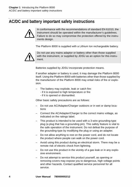
AC/DC and battery important safety instructions
The Platform 8000 is supplied with a Lithium Ion rechargeable battery.
Batteries supplied by JDSU incorporate protection means.
If another adapter or battery is used, it may damage the Platform 8000 itself. Using the Platform 8000 with batteries other than those supplied by the manufacturer of the Platform 8000 may entail risks of fire or explo-sion.
– The battery may explode, leak or catch fire:- if it is exposed to high temperature or fire- if it is opened or dismantled.
Other basic safety precautions are as follows:
– Do not use AC/Adapter/Charger outdoors or in wet or damp loca-tions
– Connect the AC/Adapter/Charger to the correct mains voltage, as indicated on the ratings label.
– This product is intended to be used with a 3-wire grounding-type plug (a plug that has a grounding pin). This safety feature is vital to the safe operation of the instrument. Do not defeat the purpose of the grounding-type by modifying the plug or using an adapter.
– Do not allow anything to rest on the power cord, and do not locate the product where people can walk on the power cord.
– Avoid using this product during an electrical storm. There may be a remote risk of electric chock from lightning.
– Do not use this product in the vicinity of a gas leak or in any explo-sive environment.
– Do not attempt to service this product yourself, as opening or removing covers may expose you to dangerous, high voltage points and other hazards. Contact qualified service personnel for all service.
In conformance with the recommendations of standard EN 61010, the instrument should be operated within the manufacturer’s guidelines. Failure to do so may compromise the protection offered by the instru-ments design.
Do not use any mains adaptor or battery other than those supplied with the instrument, or supplied by JDSU as an option for this instru-ment.
4 User Manual 780000002/12

Chapter 1 Introducing the Platform 8000Architecture
The Platform 8000 is equipped with two mains:
– a main supply for optical configurations
– a high power supply for configurations with at least one Transport Module.
ArchitectureThe architecture of the Platform 8000 is based on the superimposition of modules and receptacles to accommodate interchangeable plug-in measurement units. This structure adapts to current applications in fiber optics and will adapt to future applications.
By the addition of modules and receptacles, a lightweight battery-oper-ated field instrument suitable for optical network maintenance can be converted into a complete apparatus with a high-level of performance and functions for the installation and upgrading of fiber optic networks.
Modules and plug-in units are easily interchangeable in the field, reducing the number of instruments to be carried.
Whatever its configuration, the Platform 8000 has a user interface module with screen and controls, fixed to a base: either a finishing back-plate, if the instrument is to be used only on the mains, or a module containing the batteries.
Maximum configuration of the Platform 8000
In addition to the user interface module and the rear module, the Platform 8000 can include up to four measurement modules, including two recep-tacle modules, each able to accommodate two plug-ins.
Fig. 2 Possible configurations of the Platform 8000
User Manual 780000002/12 5

Chapter 1 Introducing the Platform 8000User interface
User interfaceThe topmost element of the Platform 8000 constitutes the user interface.
It is equipped with:
– a 10.4 inch TFT color screen, standard or high visibility (optimized for outdoor use), which can be touchscreen
– hard keys or tactile keys (option)
– numerous functions such as Fault Locator VFL (Visual Fault Loca-tion), source power meter, optical microscope, talkset, etc.
– remote front panel function, data transfer, etc.
The particularly simple user interface means familiarity with the instru-ment is quickly attained. This interface remains the same, irrespective of the options and modules with which the instrument may be equipped.
An external keyboard and a mouse (on option) facilitate data input.
TechnologyThe Platform 8000 employs multi-tasking for the simultaneous perfor-mance of several operations (such as acquisition, parameters modifica-tion, trace analysis, printing) and several functions (for example OSA, OTDR or BERT measurements).
The measurement results can be stored in the internal memory (16 Mb), or on the following options:
– hard disk (min 10 Gb),
– floppy disk or CD ROM,
– plug-in media (USB memory stick or Flash compact memory).
Mechanical strengthAlthough it is extremely light, the housing of the Platform 8000 can resist harsh environmental conditions:
– its rubber protectors give it high shock resistance
– it resists water splashes.
The modules and receptacles are very simple to install, requiring only a single tool which is incorporated in the instrument.
6 User Manual 780000002/12
Chapter 1 Introducing the Platform 8000Software
SoftwareThe software can be easily updated from a CD-ROM, the Ethernet, a USB stick or a Flash memory card.
MeasurementsThe Platform 8000 can be used to test fiber optic networks:
– during the phase of design and production of equipment
– during the phase of installation and validation of such equipment in a network
– during the phase of network maintenance.
User Manual 780000002/12 7

Chapter 1 Introducing the Platform 8000Measurements
8 User Manual 780000002/12

Chapter 2 Starting up
2
This chapter explains the operations to be carried out before using the Platform 8000.The topics discussed in this chapter are as follows:
– “Unpacking the instrument” on page 10
– “Assembling the component parts of the Platform 8000” on page 10
– “Choosing the position of the instrument on the work surface” on page 19
– “Battery management” on page 20
– “Switching the Platform 8000 on and off” on page 25
– “Presentation page of the Platform 8000” on page 27
– “Troubleshooting” on page 28
User Manual 780000002/12 9

Chapter 2 Starting upUnpacking the instrument
Unpacking the instrumentRemove the Platform 8000 and its accessories from the packing case. Check that the receptacles, modules and accessories ordered are all there.
If any part is missing or damaged please contact your local JDSU agent.
The Platform 8000 is delivered with the following accessories:
– a user manual
– a backplate or a battery pack containing a battery which must be charged before use.
– a mains adapter used for mains operation of the instrument and battery charging (this adapter can also be delivered with the Trans-port Module).
– a soft carrying case (option)
– a hard carrying case (option)
Assembling the component parts of the Platform 8000– Assembly starts from the Interface module, which is placed face
down on the work surface.
– The module(s) and receptacle(s) must then be fixed in place one after the other, using the key provided, which is fixed either inside the backplate or in the battery pack. Use this key to screw in the knurled knob at each corner.
– When the last module or receptacle has been fixed, put the key back in its place, then position the backplate module or the battery pack. Fix it by tightening the four screws at the corners.
Fitting andremoving amodule orreceptacle
Before installing or removing a module, review the key principles provided below, and gather the proper tools.
The Platform 8000 must be switched off, and if it is operating on the mains, its supply cable must be unplugged.
10 User Manual 780000002/12

Chapter 2 Starting upAssembling the component parts of the Platform 8000
Key principles When connecting or disconnecting modules, focus on the following prin-ciples to ensure a secure connection and avoid damaging the connec-tors:
Alignment. Ensure that the holes on the corners of the Module or Battery Module are aligned with the holes on the component you are attaching it to. For example, if you are attaching the Optical Module to the base unit, ensure that the holes of the module are aligned with the holes on the base unit.
Parallel position. Ensure that you are holding the Module or Battery Module in a position parallel to the base unit or Module (as illustrated in Figure 6 on page 14). If either module is held at even a slight angle, there is a risk of damage to the connectors.
Proper torque. Ensure that you tighten the screw using the hex key (for the Module) or a flat blade screwdriver (for the Battery Module) until you feel a slight resistance, and then tighten it using an additional 1/4 turn. If you are using a torque wrench, apply 1.5 N-m (13.3 in-lb) to the final turn.
Required tools Large, flat blade screwdriver
You will need a large, flat blade screwdriver to remove and then replace the battery module on the base unit.
Hex key (provided)
A 5 mm hex key is provided in a groove on the inside panel of the battery module. This key is used to secure and then tighten the screws that connect the module to the base unit.
Torque wrench (optional)
If you want to ensure that you don’t apply too much pressure when connecting or disconnecting modules, you can optionally use a torque wrench capable of applying 1.5 N-m (13.3 in-lb). A torque wrench with the ability to apply up to 20 in-lb in 0.1 in-lb increments will be adequate. You will also need a 5 mm hex key bit for the wrench.
Assembling theinstrument
To connect the Module and Battery Module to a base unit
1 Verify that power is OFF on your base unit and that the power adapter is unplugged.
2 Using the large flat blade screwdriver, loosen each of the 4 slotted bolts on the back panel of the battery module (attached to the base unit), and then gently remove it from the base unit.
User Manual 780000002/12 11

Chapter 2 Starting upAssembling the component parts of the Platform 8000
3 Remove the hex key from the groove on the inside panel of the battery module. See Figure 3.
4 The base unit and the Optical Module each have rectangular mating connectors (see Figure 4 and Figure 5 on page 13). These connec-tors must be aligned carefully before connecting the module to the base unit.
Fig. 3 Hex key groove in battery module
Fig. 4 Base Unit Mating Connector
Hex Key groove
Base Unit Mating Connector
12 User Manual 780000002/12

Chapter 2 Starting upAssembling the component parts of the Platform 8000
To align the connectors properly:
a Position the Module over the base unit, with the Module’s mating connector directly over the mating connector on the base unit.
b Verify that the holes on each corner of the Module are aligned precisely with the holes on each corner of the base unit.
c IMPORTANT: Risk of damage to connectors. Verify that you are holding the Module in a position parallel to the base unit (see Figure 6). If the module is tilted at even a slight angle, the mating connectors may not connect properly, and you may damage the connectors.
Fig. 5 Module Mating Connector
Module Mating Connector
User Manual 780000002/12 13

Chapter 2 Starting upAssembling the component parts of the Platform 8000
5 Slowly lower the Optical Module until it is just over the holes on the base unit, and then gently but firmly press the center of the module to attach it to the base unit.
6 Starting at the upper right corner, do the following:
a Hex key. Using the hex key that you removed from the battery module, tighten screws 1 through 4 (in the sequence illustrated in Figure 7) until you feel a slight resistance.
b Hex key or torque wrench. Use the hex key to tighten each screw one additional quarter-turn, or if you are using a torque wrench, tighten each screw by applying an additional 1.5 N-m (13.3 in-lb). Use the same sequence illustrated in Figure 7.
Fig. 6 Proper alignment of Module and Base Unit
Optical Module
Base Unit
parallel positionalign align
14 User Manual 780000002/12

Chapter 2 Starting upAssembling the component parts of the Platform 8000
7 After the Optical Module is secured to the base unit, put the hex key back in the groove in the Battery Module, and then do the following:
a Position the battery module over the Optical Module, with the battery module’s mating connector directly over the mating connector on the Optical Module.
b Verify that the holes on each corner of the battery module are aligned precisely with the holes on each corner of the Optical Module.
c IMPORTANT: Risk of damage to connectors. Verify that you are holding the battery module in a position parallel to the Optical Module, similar to that illustrated in Figure 6 on page 14. If the module is tilted at even a slight angle, the mating connec-tors may not connect properly, and you may damage the connectors.
8 Slowly lower the Battery Module until it is just over the holes on the Optical Module, and then gently but firmly press the center of the Battery Module to attach it to the Optical Module.
9 Starting at the upper right corner, do the following:
a Using the large flat blade screwdriver, tighten screws 1 through 4 until you feel a slight resistance. Use the same sequence illus-trated for the Optical Module screws in Figure 7.
Fig. 7 Sequence for securing and tightening the screws
1
2
34
User Manual 780000002/12 15

Chapter 2 Starting upAssembling the component parts of the Platform 8000
b Tighten each screw one additional quarter-turn in the sequence illustrated in Figure 7 on page 15, or, if you are using a torque wrench, tighten each screw an additional 1.5 N-m (13.3 in-lb).
The Optical Module is connected to the base unit and can be used for testing.
Disconnectingthe Module
Before disconnecting the Optical Module from the base unit, review the “Key principles” on page 11 for assembling the instrument. The same principals apply when disassembling the various components.
Required tools Large, flat blade screwdriver
You will need a large, flat blade screwdriver to remove the battery module.
Hex key (provided)
A 5 mm hex key is provided in a groove on the inside panel of the battery module. This key is used to secure and then tighten the screws that connect the module to the base unit.
Torque wrench (optional)
If you want to ensure that you don’t apply too much pressure when connecting or disconnecting modules, you can optionally use a torque wrench capable of applying 13.3 in-lb. A torque wrench with the ability to apply up to 20 in-lb in 0.1 in-lb increments will be adequate. You will also need a 5 mm hex key bit for the wrench.
Disassembling theinstrument
To remove the Module from a base unit
1 Verify that power is OFF on your base unit and that the power adapter is unplugged.
2 Using the large flat blade screwdriver, loosen each of the 4 slotted bolts on the back panel of the battery module (attached to the base unit), and then gently remove the battery module.
3 Use the provided hex key to loosen screws 1 through 4 in the sequence illustrated in Figure 7 on page 15.
4 Turn the base unit over so the display is facing upwards.
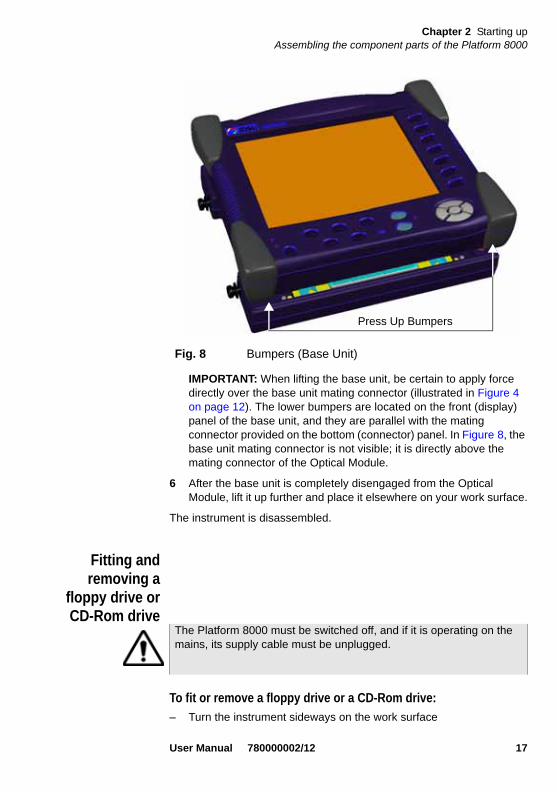
5 Disconnect the Optical Module from the base unit by gently pressing upwards on the two lower bumpers of the base unit as illustrated in Figure 8.
16 User Manual 780000002/12
Chapter 2 Starting upAssembling the component parts of the Platform 8000
IMPORTANT: When lifting the base unit, be certain to apply force directly over the base unit mating connector (illustrated in Figure 4 on page 12). The lower bumpers are located on the front (display) panel of the base unit, and they are parallel with the mating connector provided on the bottom (connector) panel. In Figure 8, the base unit mating connector is not visible; it is directly above the mating connector of the Optical Module.
6 After the base unit is completely disengaged from the Optical Module, lift it up further and place it elsewhere on your work surface.
The instrument is disassembled.
Fitting andremoving a
floppy drive orCD-Rom drive
To fit or remove a floppy drive or a CD-Rom drive:
– Turn the instrument sideways on the work surface
Fig. 8 Bumpers (Base Unit)
Press Up Bumpers
The Platform 8000 must be switched off, and if it is operating on the mains, its supply cable must be unplugged.
User Manual 780000002/12 17

Chapter 2 Starting upAssembling the component parts of the Platform 8000
– Completely unscrew the 2 big screws located at each side of the the floppy or CD-Rom drive.
– Screw them back in the adjacent holes, located on the floppy or CD-Rom drive (or remove the caps).
– Pull on the screws to remove the plug-in. Unscrew the screws which will be used for the new plug-in.
– Set the new plug-in and screw it at each side of the plug-in.
Installing andremoving a
plug-in unit in areceptacle
A plug-in may be put into either of the two slots provided for the purpose.
When a slot is vacant, it is closed by means of a cover plate fitted with two captive screws like those used on the plug-in.
Removing a plug-in from a receptacle
Fig. 9 Move the screws to new holes to fit or remove the drive
Screws
Fig. 10 Rear view of the Platform 8000
Captive screws fixing the plug-in
The Platform 8000 must be switched off and, if it is operating on the mains, its supply cable must be unplugged.
18 User Manual 780000002/12

Chapter 2 Starting upChoosing the position of the instrument on the work surface
1 Unscrew the two captive fixing screws of the plug-in completely (up to the stop).
2 Carefully slide the plug-in out of its slot.
Inserting a plug-in unit into a receptacle
1 Slide the plug-in into its slot.
2 When the plug-in is fully home, press firmly on the screen-printed face of the plug-in while tightening the clamping screws. The screen-printed face of the plug-in must be flush with that of the receptacle.
3 Make sure that the two large captive screws of the plug-in are screwed fully home.
Choosing the position of the instrument on the work surfaceDepending on the conditions of use of the Platform 8000, the instrument may be placed on a flat surface or held in the hand.
When used on a work surface, the Platform 8000 should be supported on its stay, which can be set in either of two positions, depending on whether the user is standing or sitting.
To change the stay from “seated user” position to “standing user” posi-tion, press both sides to slide the stay towards the upper end of its groove, as shown in the drawings below.
The Platform 8000 must be switched off and, if it is operating on the mains, its supply cable must be unplugged.
Fig. 11 Stay in positions for seated user and standing user
User Manual 780000002/12 19
Chapter 2 Starting upBattery management
Fitting thecarrying handle
or strap
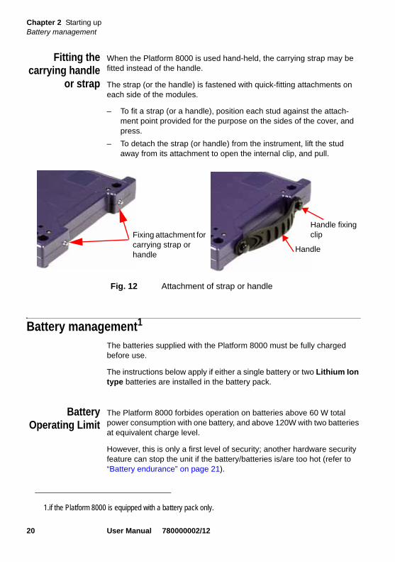
When the Platform 8000 is used hand-held, the carrying strap may be fitted instead of the handle.
The strap (or the handle) is fastened with quick-fitting attachments on each side of the modules.
– To fit a strap (or a handle), position each stud against the attach-ment point provided for the purpose on the sides of the cover, and press.
– To detach the strap (or handle) from the instrument, lift the stud away from its attachment to open the internal clip, and pull.
Battery management1
The batteries supplied with the Platform 8000 must be fully charged before use.
The instructions below apply if either a single battery or two Lithium Ion type batteries are installed in the battery pack.
BatteryOperating Limit
The Platform 8000 forbides operation on batteries above 60 W total power consumption with one battery, and above 120W with two batteries at equivalent charge level.
However, this is only a first level of security; another hardware security feature can stop the unit if the battery/batteries is/are too hot (refer to “Battery endurance” on page 21).
Fig. 12 Attachment of strap or handle
Fixing attachment for carrying strap or handle
Handle
Handle fixing clip
1.if the Platform 8000 is equipped with a battery pack only.
20 User Manual 780000002/12

Chapter 2 Starting upBattery management
Charging thebatteries
Connecting themains adapter
– At the side of the Platform 8000 (bottom right-hand corner), lift up the power supply socket protector and plug in the mains adapter.
– Connect the adapter to the mains. The On/Off indicator lamp starts to blink.
Charging If the instrument is fitted with batteries, on connection to the mains:
– if the user does not press ON within 20 seconds, the batteries will go on to rapid charge. In this case, the Charge indicator will go on.
– if the user presses the ON key before rapid charge begins, the instrument starts up and the batteries will be charged at low rate during use.
If there are two batteries, they will be charged one after the other. As soon as the batteries are fully charged, the Charge indicator lamp goes off.
Battery chargingtime
If the battery is completely discharged, the time taken to recharge is:
– about 2.5 hours, if the apparatus is not in use (On/Off indicator off)
– about 9 hours if the instrument is used during charging (On/Off indi-cator On).
Battery endurance One standard battery is only guaranteed to deliver 30W at ambient temperature. During discharge, battery increases its temperature.Above 30W at ambient temperature, the message Battery too hot, please turn power off may be displayed on the screen, inviting the user to shut off the equipment.
Use only the mains adapter supplied with the Platform 8000. The adapter for some other electronic device may appear to be identical, but entails a risk of damage to the Platform 8000.
It is essential to wait until charging is complete to ensure maximum independent operating time, which may otherwise be considerably reduced.
User Manual 780000002/12 21
Chapter 2 Starting upBattery management
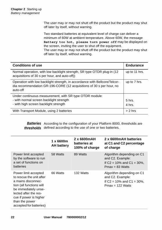
The user may or may not shutt off the product but the product may shut off later by itself, without warning.
Two standard batteries at equivalent level of charge can deliver a minimum of 60W at ambient temperature. Above 60W, the message Battery too hot, please turn power off may be displayed on the screen, inviting the user to shut off the equipment.The user may or may not shutt off the product but the product may shut off later by itself, without warning.
Batteriesthresholds
According to the configuration of your Platform 8000, thresholds are defined according to the use of one or two batteries.
Conditions of use Endurance
Normal operation, with low backlight strength, SR type OTDR plug-in (12 acquisitions of 30 s per hour, and auto-off))
up to 11 hrs.
Operation with low backlight strength, in accordance with Bellcore/Telcor-dia recommendation GR-196-CORE (12 acquisitions of 30 s per hour, no auto-off
up to 7 hrs.
Under continuous measurement, with SR type OTDR module:- with normal screen backlight strength- with high screen backlight strength
5 hrs. 4 hrs.
With Transport Module, using 2 batteries > 2 hrs
1 x 6600m AH battery
2 x 6600mAH batteries at 100% of charge
2 x 6600mAH batteries at C1 and C2 percentage of charge
Power limit accepted by the software to run a set of functions on batteries
58 Watts 89 Watts Algorithm depending on C1 and C2. Example:If C2 = 10% and C1 = 30%, Pmax = 83 Watts
Power limit accepted to rescue the unit after a mains disconnec-tion (all functions will be immediately unse-lected after the res-cue if power is higher than the power accepted for batteries)
66 Watts 132 Watts Algorithm depending on C1 and C2. Example:If C2 = 10% and C1 = 30%, Pmax = 122 Watts
22 User Manual 780000002/12

Chapter 2 Starting upBattery management
An example:
If the MTS8000 is connected to a 150 Watts external power supply:
– Actual power consumption is of 40 Watts and we disconnect the mains: the battery will run the product.
– Actual power consumption is of 60 Watts and we disconnect the mains: the battery will run the product but ISU software will immedi-ately shut all the selected function off.
– Actual power consumption is of 70 Watts and we disconnect the mains: the battery is not connected and the unit will shut down brutally.
Charge and Onindicators
– On indicator blinking: the instrument is switched off but connected to an external power source.
– On steady: the instrument is operating, either on batteries or with an external power source.
– Charge indicator on: the instrument is connected to an external power source and the batteries are on charge.
Battery chargelevel display
When one or two batteries are installed in the instrument, their charge level is displayed in green in a graphic in the top left-hand corner of the screen and also as a charge percentage. Example: .
A yellow or red suqare is displayed under the battery charge level display when the main is disconnected from the equipment:
– : power budget is between 58W and 70W with one battey, and between 89W and 120W with two batteries. In this case, once AC/DC adapter is unplugged, the mainframe will delay for 1 minute and, if the adapter is not reconnected, the unit will deselect all func-tions available.
Those limits are the one accepted by the software but in any case, a battery delivering 58 Watts will heat very fast and its hardware security can potentially be activated before the unit shuts down by itself because of a too high temperature. The power limit delivered by a battery for a long term is around 30 Watts.
It is essential to wait until charging is complete for maximum battery endurance, otherwise this may be considerably reduced and the level of charge may not be correctly displayed.
User Manual 780000002/12 23

Chapter 2 Starting upBattery management
– : when the AC/DC adapter is disconnected, the battery/batteries will not be able to set in backup mode (power budget greater than 70W with one battery, and greater than 120W with 2 batteries). The unit will shut off automatically.
When the instrument is in use, if there are two batteries, they both discharge gradually. The instrument operates initially on the battery with the higher level of charge, then switches over automatically from one to the other as they lose their charge.
– If the battery charge level is too low (less than 10%), a message is displayed. In this situation, results must be stored and the Platform 8000 switched off (ON/OFF button).
– When the battery charge level drops below 5%, an audio signal is emitted at intervals and an exclamation point is displayed next to the icon . When the level becomes too low, the instrument switches off automatically after saving the current configuration.
Access to thebatteries
– Switch off the instrument and disconnect the mains supply.
– Turn the instrument face down on the work surface.
– Slacken the captive screws at the four corners with a coin and unscrew them.
– Lift the battery pack to disconnect it from the base, withdraw it and turn it over on the work surface.
– Unscrew the two central knurled screws (a) and remove the cover of the battery pack. The batteries can then be removed, taking care not to damage the connectors into which they are plugged.
NOTE
The battery charge level indication is displayed in orange, when a communication issue occured.
Fig. 13 Battery seatings
Key Knurled screws (a) Batteries
24 User Manual 780000002/12
Chapter 2 Starting upSwitching the Platform 8000 on and off
When putting the batteries back into their seatings, make sure that their connectors engage correctly with those of the module. Then fit the battery pack back on to the base.
Safetyrecommendatio
ns
The Lithium Ion batteries are designed for maximum safety. In particular, each cell is provided with a safety valve to prevent excessive internal pressure in the event of overcharging or exposure to very high tempera-tures.
If you do not intend to use the Platform 8000 for several weeks, it is advis-able to remove the batteries in order to prolong their useful life, and to recharge them fully before using them again.
In case of communication problems with the battery,informed to the user, the battery charging information is no more actualized.Restart the equipment to restore the communication with battery.
Switching the Platform 8000 on and offThe mains adapter is used not only for charging the battery (if the battery pack is installed), but also for operating the Platform 8000 on the mains, if a mains socket is at hand, to save the battery.
Switching onthe Platform
8000
Switching on using the battery
– Press the ON/OFF key. The On indicator lights up.
– The JDSU logo appears on the screen briefly, then an autotest is carried out, the software is installed (this just takes a few seconds), then the screen goes dark for about three seconds. Finally the opening screen appears (see "Presentation page of the Platform 8000" page 27).
Make sure that the connectors of the battery pack engage properly with those of the base. Tighten the knurled screws at the four corners, as securing the battery pack by the connectors alone will not ensure uninterrupted operation.
Use only the batteries supplied with the Platform 8000. Batteries sup-plied with other electronic devices may appear to be identical, but entail a risk of damage to the Platform 8000.
User Manual 780000002/12 25

Chapter 2 Starting upSwitching the Platform 8000 on and off
Mains operation
If the instrument is to operate on the mains:
– lift the protective cover over the power supply socket on the side of the Platform 8000 (bottom right-hand corner) and plug in the mains adapter.The JDSU logo shows briefly and is followed by an autotest. Then the On indicator starts to blink: the instrument is ready to start up.
– press the ON key (if this is not done, and the instrument is equipped with a battery, it will switch over to rapid charging of the battery after about 20 seconds).
Switching offthe Platform
8000
While the Platform 8000 is operating, press the ON/OFF button to switch it off.
NOTE
It is possible to switch over from battery to mains operation, or vice versa, without loss of data.
The module cannnot be swapped when the unit is ON or AC powered
In the event of an unexpected mains power cut, if there is no battery, the current results and configuration will not be saved. Next time the instrument is switched on, it will return to its initial configuration.
Disconnect the jack connector of the AC/DC power supply before disconnecting the AC/DC mains
NOTE
When the instrument is switched off using the ON/OFF button, current results and configuration are saved. Next time the ON/OFF key is pressed, they are recalled.
26 User Manual 780000002/12

Chapter 2 Starting upPresentation page of the Platform 8000
Reset If the Platform 8000 freezes, prolonged pressure (about 4 s.) on the ON/OFF key will reset the instrument.
Presentation page of the Platform 8000The presentation page of the instrument is called up by pressing the SYSTEM button, followed by Page Help. It also appears when the instru-ment is switched on.
This page shows:
1 the version of the software installed in the instrument,
2 the hardware options: CD-RW, hard disk, floppy disk drive, modem, talkset, power meter, VFL. Those that are installed in the instrument are marked with a green tick.
3 the modules installed (including serial number and date of last cali-bration) as well as any batteries present (including serial number).
4 Click on Services Data to replace the software version list by the services data (CPU, Memory, CPU board, and screen reference)
NOTE
With mains, wait for the message «It is now safe to unplug external power» or for the black screen before unpluging the main plug.
Fig. 14 Example of presentation screen
Services Data
User Manual 780000002/12 27

Chapter 2 Starting upTroubleshooting
Troubleshooting
Troubleshooting Solution
Nothing happens when the ON/OFF key is pressed.
Make sure that an internal battery is present or the mains adapter is properly connected.
You are using the Platform 8000 in the ordinary way when it suddenly switches off.
The parameters of the instrument may have been set so that it switches off automatically after 5 minutes of inactivity to save the battery. Work in progress is first saved in the memory. See ."Screen saver" page 56. Otherwise, check the battery charge level.
The battery refuses to charge (the charge indicator does not go on when the instru-ment is connected to the mains and is not operating).
There is no battery in the instru-ment, or the battery is already fully charged.
28 User Manual 780000002/12

Chapter 3 Controls of the Platform 8000
3
This chapter describes the controls of the Platform 8000.The topics discussed in this chapter are as follows:
– “Control interface” on page 30
– “Using an external keyboard, mouse and screen touch (options)” on page 33
– “Editing” on page 35
– “Accessing the Platform 8000 from a PC” on page 39
– “Connectors” on page 44
– “Floppy disk or CD-ROM drive (option)” on page 46
– “Serial port (RS 232 - not used)” on page 46
– “SVGA connector” on page 47
– “CompactFlash port” on page 47
The Platform 8000 is a multi-tasking instrument: the user can simulta-neously carry out an acquisition, modify the configuration parameters, print out results and access the directory of the internal memory or the floppy disk. In some cases, it is even possible to perform several measurement operations at the same time, but only the result of the function selected can be displayed.
User Manual 780000002/12 29
Chapter 3 Controls of the Platform 8000Control interface
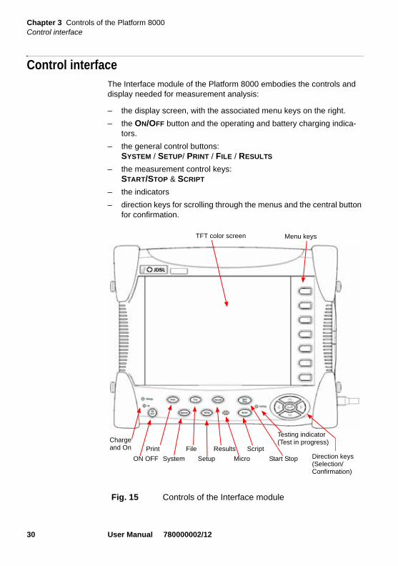
Control interfaceThe Interface module of the Platform 8000 embodies the controls and display needed for measurement analysis:
– the display screen, with the associated menu keys on the right.
– the ON/OFF button and the operating and battery charging indica-tors.
– the general control buttons: SYSTEM / SETUP/ PRINT / FILE / RESULTS
– the measurement control keys:START/STOP & SCRIPT
– the indicators
– direction keys for scrolling through the menus and the central button for confirmation.
Fig. 15 Controls of the Interface module
Menu keys TFT color screen
ON OFF
Charge and On Print
System
File
Setup
Results
Micro
Script
Start Stop
Testing indicator(Test in progress)
Direction keys (Selection/Confirmation)
30 User Manual 780000002/12
Chapter 3 Controls of the Platform 8000Control interface
TFT displayscreen
The Platform 8000 has a large, 10.4 inch TFT color screen, SVGA defi-nition (800 x 600 pixels), back-lit:
– either a standard TFT screen
– or a high visibility TFT screen, for best visibility outdoors and indoors.
The high visibility screen supplied may also be a touch screen (option).
The different zones of the screen
The display is divided into 3 zones:
1 the central zone, displaying the configuration or the results of measurements.
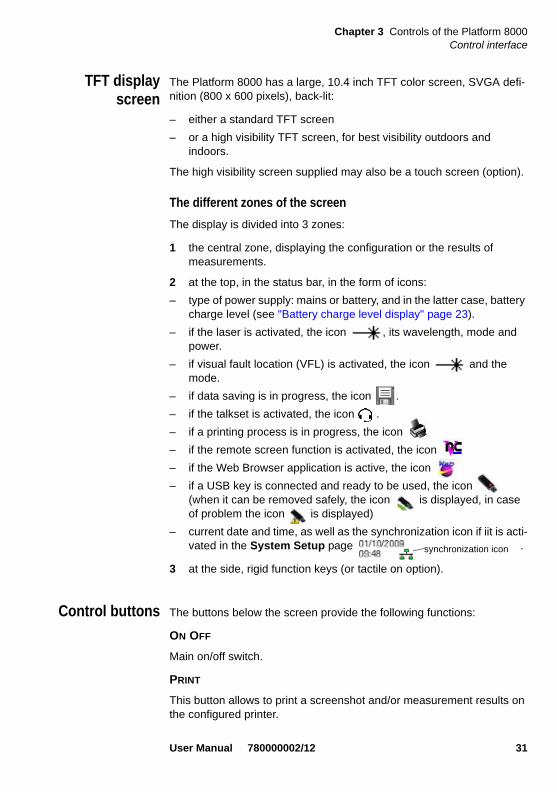
2 at the top, in the status bar, in the form of icons:
– type of power supply: mains or battery, and in the latter case, battery charge level (see "Battery charge level display" page 23).
– if the laser is activated, the icon , its wavelength, mode and power.
– if visual fault location (VFL) is activated, the icon and the mode.
– if data saving is in progress, the icon .
– if the talkset is activated, the icon .
– if a printing process is in progress, the icon
– if the remote screen function is activated, the icon
– if the Web Browser application is active, the icon
– if a USB key is connected and ready to be used, the icon (when it can be removed safely, the icon is displayed, in case of problem the icon is displayed)
– current date and time, as well as the synchronization icon if iit is acti-vated in the System Setup page .
3 at the side, rigid function keys (or tactile on option).
Control buttons The buttons below the screen provide the following functions:
ON OFF
Main on/off switch.
This button allows to print a screenshot and/or measurement results on the configured printer.
synchronization icon
User Manual 780000002/12 31

Chapter 3 Controls of the Platform 8000Control interface
SYSTEM
This button gives access to:
– selection of the different measurement or base functions
– the configuration menus of the instrument (choice of module(s) used), When the instrument is switched off, its configuration is stored in the memory, as are the measurement results.
– the configuration menus of the system (screen, date, language, print-out, etc.).Once you have pressed the System Setup key, you can select:
– the display parameters: screen illumination, automatic shut-down, validation of VGA output.
– the parameters specific to the country of use: date, time, format of date/time, language.
– the input/output parameters: optical switch, Ethernet, Modem, e-mail configuration.
– the validation of the loudspeaker
– the initialization of automatic shutdown of the instrument.
For a complete description, see "System set-up" page 49.
SETUP
This button calls up the measurement configuration menu. This menu depends on the function in use.
RESULTS
This button calls up the results page (e.g. with OTDR module: reflectom-etry trace, results and table of results) and is used to analyze results.
FILE
This button calls up the file and directory management menu.
It allows to:
– to choose the storage medium: internal memory, hard disk, floppy disk or CD-ROM, USB memory stick, Flash compact memory card; file name and format; information relating to the data stored in the file.
– to store files or retrieve them for selection, copying or deletion; with facilities for classifying them in directories and sub-directories.
NOTE
The configuration menus can be displayed, and modified if required during acquisition or measurement.
32 User Manual 780000002/12
Chapter 3 Controls of the Platform 8000Using an external keyboard, mouse and screen touch (options)
Two buttons can be used to start a measurement:
START/STOP
Starts and stops the measurement.
SCRIPT
Is used to enter a sequence of commands and execute it.
Indicators On/Off - blinking: the instrument, though connected to anexternal power source, is switched off.
- on: the instrument is operating, either by battery or onan external power supply.
Charge on: the instrument is connected to an external powersource and the batteries are on charge.
Testing on: at least one function is in measurement phase (forexample, the laser emission pilot for an OTDRmeasurement).
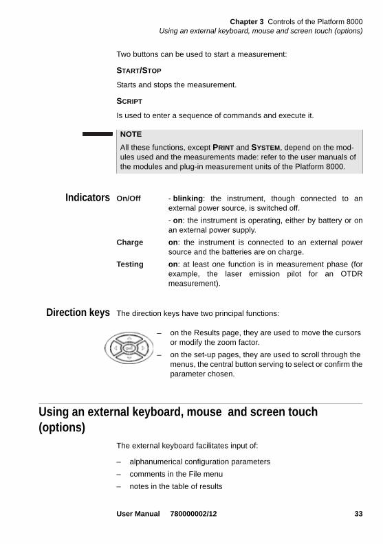
Direction keys The direction keys have two principal functions:
Using an external keyboard, mouse and screen touch (options)
The external keyboard facilitates input of:
– alphanumerical configuration parameters
– comments in the File menu
– notes in the table of results
NOTE
All these functions, except PRINT and SYSTEM, depend on the mod-ules used and the measurements made: refer to the user manuals of the modules and plug-in measurement units of the Platform 8000.
– on the Results page, they are used to move the cursors or modify the zoom factor.
– on the set-up pages, they are used to scroll through the menus, the central button serving to select or confirm the parameter chosen.
User Manual 780000002/12 33

Chapter 3 Controls of the Platform 8000Using an external keyboard, mouse and screen touch (options)
– editing characters
The mouse can be used instead of the direction keys to scroll through menus and make a selection.
Connect the keyboard and mouse to the USB connectors.
Virtual controlbuttons bar
It is possible to emulate hard keys with Virtual Control buttons
To display these buttons, click once on the top of the screen in the status bar, at the same height than the date and time.
The virtual control buttons bar is displayed during a few seconds. You may click on any of these buttons to obtain exactly the same results than using the real buttons in the front panel of the Platform 8000.
Equivalencebetweenexternal
keyboard andPlatform 8000
Although it is intended primarily to replace the Edit menu of the Platform 8000, the external keyboard can replace all the buttons and keys of the Platform 8000 except the ON/OFF button:
– The menu keys to the right of the screen are replaced by the func-tion keys F1 to F7.
– The buttons below the screen are equivalent to Ctrl + a letter (see table below).
– The direction keys have the same function on the external keyboard and on the Platform 8000.
Fig. 16 Virtual control buttons bar
The virtual control buttons bar can not be displayed within desktop applications (see Chapter 8 “Desktop applications” page 103).
NOTE
This virtual control buttons bar is especially useful when the Platform 8000 screen is exported on a remote PC (see "Transfer of the inter-face of the Platform 8000 on to a PC" page 41).
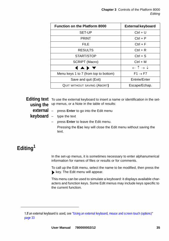
Function on the Platform 8000 External keyboard
SYSTEM Ctrl + Y
34 User Manual 780000002/12
Chapter 3 Controls of the Platform 8000Editing
Editing textusing the
externalkeyboard
To use the external keyboard to insert a name or identification in the set-up menus, or a Note in the table of results:
– press Enter to go into the Edit menu
– type the text
– press Enter to leave the Edit menu.
Pressing the Esc key will close the Edit menu without saving the text.
Editing1
In the set-up menus, it is sometimes necessary to enter alphanumerical information for names of files or results or for comments.
To call up the Edit menu, select the name to be modified, then press the key. The Edit menu will appear.
This menu can be used to simulate a keyboard: it displays available char-acters and function keys. Some Edit menus may include keys specific to the current function.
SET-UP Ctrl + U
PRINT Ctrl + P
FILE Ctrl + F
RESULTS Ctrl + R
START/STOP Ctrl + S
SCRIPT (Macro) Ctrl + M
Menu keys 1 to 7 (from top to bottom) F1 F7
Save and quit (Exit) Entrée/Enter
QUIT WITHOUT SAVING (ABORT) Escape/Echap.
Function on the Platform 8000 External keyboard
1.If an external keyboard is used, see "Using an external keyboard, mouse and screen touch (options)"page 33
User Manual 780000002/12 35
Chapter 3 Controls of the Platform 8000Editing
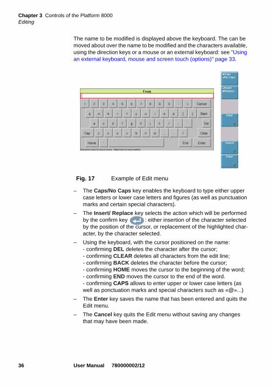
The name to be modified is displayed above the keyboard. The can be moved about over the name to be modified and the characters available, using the direction keys or a mouse or an external keyboard: see "Using an external keyboard, mouse and screen touch (options)" page 33.
– The Caps/No Caps key enables the keyboard to type either upper case letters or lower case letters and figures (as well as punctuation marks and certain special characters).
– The Insert/ Replace key selects the action which will be performed by the confirm key : either insertion of the character selected by the position of the cursor, or replacement of the highlighted char-acter, by the character selected.
– Using the keyboard, with the cursor positioned on the name: - confirming DEL deletes the character after the cursor;- confirming CLEAR deletes all characters from the edit line;- confirming BACK deletes the character before the cursor;- confirming HOME moves the cursor to the beginning of the word;- confirming END moves the cursor to the end of the word.- confirming CAPS allows to enter upper or lower case letters (as well as ponctuation marks and special characters such as «@»...)
– The Enter key saves the name that has been entered and quits the Edit menu.
– The Cancel key quits the Edit menu without saving any changes that may have been made.
Fig. 17 Example of Edit menu
36 User Manual 780000002/12

Chapter 3 Controls of the Platform 8000Editing
To enter text:
– Press the Caps/No Caps key, depending on the case of the char-acter to be entered.
To delete characters in a text:
To insert characters in a text:
Without Touch Screen Using Touch Screen- Using the direction keys, move the cursor onto the first character required.
- Press the validation key.
The character will appear in the upper box.
- Repeat the process for the remaining characters.
- Directly click onto the character you want.
The character will appear in the upper box.
- Repeat the process for the remaining characters.
Without Touch Screen Using Touch Screen- Go into Replace mode and move the cursor on to the character to be deleted.
- Move the cursor on to Back (or Del) and press the valida-tion key.
Repeatedly pressing this same key will delete the preceding (or following) characters.
- Go into Replace mode and posi-tion the cursor on to the character to delete.
- Click on the Back touch (or Del)
Repeatedly clicking on this same key will delete the preceding (or following) characters
Without Touch Screen Using Touch Screen- Go into Insert mode and place the cursor on the name at the insertion point.
- Using the direction keys, move the cursor on to the first character to be inserted.
- Press the validation key.
Repeat the process for the other characters to be inserted.
- Go into Insert mode and place the cursor on the name at the insertion point.
- Directly click on the character you want
Repeat the process for the other characters to be inserted.
User Manual 780000002/12 37

Chapter 3 Controls of the Platform 8000Editing
Quitting the Edit menu
– Press the Cancel key to quit without saving the action performed (onto the keyboard or the screen).
– Press the Enter key to quit the menu while saving the text entered (onto the keyboard or the screen).
NumericKeypad
For some configuration parameters, you will have to enter numeric values. The direction keys of the Platform 8000 can be used. However, the user can also use the numeric keypad, displayed when the Edit Number key is pressed.
Click on EDIT NUMBER to display the Numeric Keypad.
The keys Min and Max are displayed when the parameter has a minimum and maximum value (for example, for the screen lighting level, pressing the Min key will display the value -5 and pressing the Max key will display the value +5).
The direction keys allow to increment of +/-1 the selected value.
The direction keys < > allow to select the previous or the next figure.
Clear key: delete all the displayed value (same function as the Clear key of the screen)
Cancel key: quits the Edit Number menu without saving any changes that may have been made (same function as the Cancel key of the screen)
Enter key: saves the name that has been entered and quits the Edit Number menu (same function as the Validate key of the screen).
Fig. 18 Example of Numeric Keypad
38 User Manual 780000002/12

Chapter 3 Controls of the Platform 8000Accessing the Platform 8000 from a PC
Modifying / Changing a value with the numeric keypad
When the Edit Number menu is oopened, the first figure of the value is selected.
Accessing the Platform 8000 from a PCThe Platform 8000 can be connected to a PC in order to:
– remote the screen of the Platform 8000 on to the PC and issue commands from the keyboard of the PC
– access the internal memory (or hard disk) of the Platform 8000 from the PC and transfer files from the Platform 8000 to the PC and vice versa.
Connecting thePlatform 8000
to a PC
Direct connection 1 On the PC: find the IP address and the mask of the PC’s sub-network:
– With Windows 98 or Millenium: Select Start > Execute, then enter winipcfg2 and click on OK.
– With Windows NT, 2000, XP or Vista: select Start > Programs > Accessories > Dos Prompt, type ipconfig1, then Enter.
Note the IP address and the mask of the PC’s sub-network.
Without Touch Screen Using Touch Screen- Move the cursor to the first number to be inserted.
- Press the validation key.
Repeat the process for the other characters to be inserted.
- Directly click on the number to be inserted
Repeat the process for the other characters to be inserted.
NOTE
The Ethernet card of the equipment connected to the Platform 8000 must be configured to the Auto-detect mode (Auto negociation).
2.The character _ corresponds to a space.
User Manual 780000002/12 39

Chapter 3 Controls of the Platform 8000Accessing the Platform 8000 from a PC
2 On the Platform 8000: In the system set-up menu, under I/O interface > Ethernet, enter:- an IP identical to that of the PC +/- 1; for example, 10.10.50.204 if the address of the PC is 10.10.50.203.- the IP mask of the PC,- an IP gateway resembling the IP address, for example, ending with the character 1.
3 Connect the RJ 45 connector of the Platform 8000 to that of the PC with a crossover Ethernet cable.
4 Wait for about ten seconds while the connection is established.
5 On the PC, make sure that the connection is operational by selecting Start > Execute... and typing ping followed by the address of the Platform 8000.
Connection via alocal network
1 On the PC: find the IP address and the mask of the PC’s sub-network:
– With Windows 98 or Millenium: Select Start > Execute, then enter winipcfg3 and click on OK.
– With Windows NT, 2000, XP or Vista: select Start > Programs > Accessories > Dos Prompt, type ipconfig", then Enter.
Note the IP address and the mask of the PC’s sub-network.
2 Plug the RJ 45 connector of the Platform 8000 into a hub or Ethernet switch with a straight-through Ethernet cable
3 On the Platform 8000: In the system set-up menu, under I/O interface > Ethernet, enter the IP address, the IP mask of the PC and the IP gateway communi-cated to you by the network manager; or, on his recommendation, use dynamic attribution mode (DHCP). In this case, the address of the Platform 8000 (10.10.50.204 in the example) is displayed but cannot be altered.
4 Wait for about ten seconds while the connection is established.
5 On the PC, make sure that the connection is operational by selecting Start > Execute... and typing ping followed by the address of the Platform 8000.
3.The character _ corresponds to a space.
40 User Manual 780000002/12

Chapter 3 Controls of the Platform 8000Accessing the Platform 8000 from a PC
Transfer of theinterface of the
Platform 8000on to a PC
1 Make the Platform 8000 / PC connection as described above.
2 On the Platform 8000 in the system set-up menu, under I/O inter-face, confirm Remote screen = Session or Permanent (for more information, see "Remote screen" page 58).
3 On the PC, go into Internet Explorer and type the address: http://10.10.50.204:5800if 10.10.50.204 is the IP address of the Platform 8000 that was defined when the connection was set up.
A VNC window will open demanding a password: press Enter without typing any password.
The screen of your Platform 8000 will then appear offset on to your PC. You can use the keyboard and mouse of the PC to control the Platform 8000: see "Using an external keyboard, mouse and screen touch (options)" page 33, for the command equivalents between the controls of the Platform 8000 and those of the PC keyboard and mouse.
Moreover, via VNC window, you can launch a reboot of the equipment; to do so, click on Ctrl + Q on the PC keybord and confirm the reboot.
Accessing thehard disk of the
Platform 8000via a PC
Il is possible to access the internal memory or the hard disk of the Plat-form 8000 from a PC by means of the FTP server of the Platform 8000.
FTP access is obtained through the user accounts «mts8000» or «t-berd8000» (password: acterna).
1 Make the Platform 8000 / PC connection as described above.
2 On the PC, use either an FTP client or Internet Explorer.
3 In Internet Explorer, type the following address (10.10.50.204, which is the IP address of the Platform 8000 that was defined when the connection was set up):
ftp://mts8000:[email protected]/harddisk/if the Platform 8000 is equipped with a hard disk.
ftp://mts8000:[email protected]/disk/if the Platform 8000 is not equipped with a hard disk (access to internal memory).
For an intensive use of the deport screen or when it is used via a WAN network, it is strongly recommended to use a dedicated VNC cli-ent. The VNC clients recommended are Tight VNC (V 1.2.9) and Real VNC (V 4.1.1).
User Manual 780000002/12 41

Chapter 3 Controls of the Platform 8000Accessing the Platform 8000 from a PC
The PC then displays the contents of the hard disk or the internal memory of the Platform 8000.
Creating a shortcuttoward the
Platform 8000harddisk
You can add on your PC, a direct connection to the harddisk of the Plat-form, creating a shortcut in the network place, in the Explorer.
To create a network place, do as follows:
1 Open the Explorer on your PC
2 Double click on Add Network Place
The Wizard for the Network Place installation opens
3 Click on Next
4 In the dialog box, click on , then on Next
5 In the following dialog box, type the following address (10.10.50.204, being the IP address of the Platform 8000 defined during connection):
If you use Internet Explorer 7, the following adress must be entered:
ftp://mts8000:[email protected]/acterna/user/harddisk
NOTE
Replace ftp://mts8000:acterna by ftp://t-berd8000:acterna to use the user t-berd8000 instead of mts8000.
Fig. 19 First page of the installation
42 User Manual 780000002/12

Chapter 3 Controls of the Platform 8000Accessing the Platform 8000 from a PC
ftp://mts8000:[email protected]/harddisk (access to harddisk of the Platform 8000)
1 Click on Next
2 Enter a name for this Network Place
3 Click on Next
The PC is searching for the connexion
4 The last dialog box inform you the network place has been success-fully created, and will be open once you click on Finish.
Deselect this parameter if the internal disk of the MTS/T-BERD 8000 must not be opened on the PC.
Fig. 20 Entering the ftp address
Fig. 21 Name of the Network Place
Fig. 22 Completion of the Network Place installation
User Manual 780000002/12 43

Chapter 3 Controls of the Platform 8000Connectors
In the Explorer > Network Place, the new shortcut is displayed, with the name applied on step 2.
Connectors
Right-hand side On the right-hand side will be found:
– the connection socket for the mains adapter providing the 12 V power supply and used to charge the batteries,
– the floppy disk or CD-ROM drive (option)
Rear panel The rear panel contains, from left to right, the following elements (see example below):
– the SVGA output
– the Flash memory card reader (option)
– USB connectors for printer, mouse, keyboard, USB memory stick, etc.,
Fig. 23 Network Place created
44 User Manual 780000002/12

Chapter 3 Controls of the Platform 8000Connectors
– the RJ 11 connector for the modem option
– the DIN connector for access to external functions (future options such as Optical Switch),
– the RS 232 connector (not used),
– the RJ 45 connector for the Ethernet interface,
– if the Talkset option is present, the headset socket (jack-plug)
– if the LTS option is present, the corresponding input.
– if the Talkset option is present, the optical connector
– if the VFL option is present, the corresponding output
USB memory sticks can be very different.
They differ on Hw and Sw aspects, even inside a given brand.
In particular, USB memory sticks targeting audio recording are often formatted in very specific ways and the format is often very different from a standard FAT.
For all these reasons, we advise users to use memory sticks provided by JDSU.
In any case, USB memory sticks which are recognized by the MTS (a beep is generated when plugged on the MTS) but which cannot be read or written, should be formatted on the MTS with the Usbflash Format utility, in Expert tools > Media utilities.
If a problem occurs with the USB key you are using, contact your Local Technical Assistance Center.
Fig. 24 Example of rear panel
Interchangeable plug-ins units VFL output
RJ11USB RS 232 (not used)DIN RJ 45Memory cardSVGA
Headset Talkset
Options
Power Meter
User Manual 780000002/12 45

Chapter 3 Controls of the Platform 8000Floppy disk or CD-ROM drive (option)
Floppy disk or CD-ROM drive (option)The floppy disk drive is designed for 3.5" High Density (HD) disks, capacity 1.44 Mb.
The floppy disk is used for saving results of measurements.
The CD-ROM can be used for saving results and loading a new version of the software.
Serial port (RS 232 - not used)A 9-pin male serial connector plug (RS232 DTE) enables direct connec-tion to a modem for operation in programmed mode.
ATTENTION: For connection to a computer (a PC, for example) that operates as a DTE, use a cable reference 245 050 415, which modifies the pin corre-spondences as follows :
Platform 8000 plug Function Input/output
1 DCD ¨
2 RxD ¨
3 TxD Æ
4 DTR Æ
5 GND Æ
6 DSR ¨
7 RTS Æ
8 CTS ¨
15
9 6
Port RS232
1
6
4
2
3
5
4
1
6
3
2
5
46 User Manual 780000002/12
Chapter 3 Controls of the Platform 8000SVGA connector
SVGA connector15-pin connector used for connecting to an external monitor or projector.
Once the monitor or projector is connected, to transfer information to it, proceed as follows:
– Press the SETUP button, then the System Set up key.
– In the Screen field, position the cursor on SVGA Output and confirm Yes.
CompactFlash portThe Compact FLash port allows to add user memory or software memory (in use with the Transport Module).
Installing the CompactFlash
1 Insert the CompactFlash until it is correctly connected
2 Block the CompactFlash screwing the delivered caps.
NOTE
If the instrument is switched off, this function is automatically deacti-vated.
NOTE
The instrument must be switched off and disconnected from the main.
If the Transport Module is used by the Platform 8000, the Compact-Flash must not be removed.
User Manual 780000002/12 47

Chapter 3 Controls of the Platform 8000CompactFlash port
48 User Manual 780000002/12

Chapter 4 System set-up
4
This chapter describes the operations for configuring the instrument (choosing the module or function to be used) and the system (date, language, input/output, etc.).The topics discussed in this chapter are as follows:
– “Principle of the set-up menus” on page 50
– “Configuring the instrument” on page 50
– “Configuring the unit” on page 53
– “Standalone results” on page 65
– “Expert Tools” on page 65
– “Desktop Applications” on page 68
User Manual 780000002/12 49

Chapter 4 System set-upPrinciple of the set-up menus
The procedures described below usually use the direction keys.
When the instrument is equipped with a mouse or/and a touch
screen:
- the user must adapt the text to the option used; which means
that for touch screen and mouse, the user must directly click on
the desired field.
- to edit a string of characters, the key of the Platform 8000
must sometimes be used.
Principle of the set-up menus A set-up can be displayed or modified while an acquisition or measure-ment is in progress. The parameters that cannot be modified are greyed out. The menu thus gives all the possible options, excluding numerical values.
– To move from one parameter to another, use the direction keys and . When a parameter is selected, its possible values are shown to the right of the parameter.
– To modify the value of a parameter, use the direction keys and to highlight the option selected.
– To leave a set-up menu the user can press any of the keys below the screen or the menu key Exit.
Configuring the instrumentSince the instrument can be equipped with a range of modules and plug-ins, a variety of functions are possible. Before carrying out a particular measurement, it is therefore necessary to select the function or functions required for it
If a module has been changed, the instrument configuration menu will automatically be displayed as soon as the power is switched on.
The functions of Transport, Reflectometry, Spectrum Analysis, Polariza-tion Mode Dispersion (PMD), Chromatic Dispersion (CD), Visible Source (VFL), Power Measurement (Radiometry), Talkset (option) are not mutu-ally exclusive: several functions can be active at once.
50 User Manual 780000002/12
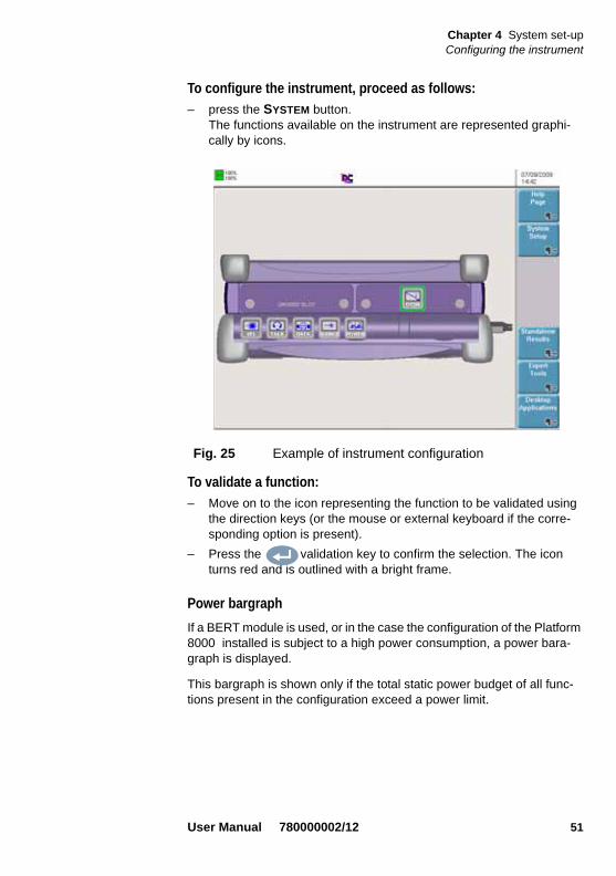
Chapter 4 System set-upConfiguring the instrument
To configure the instrument, proceed as follows:
– press the SYSTEM button.The functions available on the instrument are represented graphi-cally by icons.
To validate a function:
– Move on to the icon representing the function to be validated using the direction keys (or the mouse or external keyboard if the corre-sponding option is present).
– Press the validation key to confirm the selection. The icon turns red and is outlined with a bright frame.
Power bargraph
If a BERT module is used, or in the case the configuration of the Platform 8000 installed is subject to a high power consumption, a power bara-graph is displayed.
This bargraph is shown only if the total static power budget of all func-tions present in the configuration exceed a power limit.
Fig. 25 Example of instrument configuration
User Manual 780000002/12 51
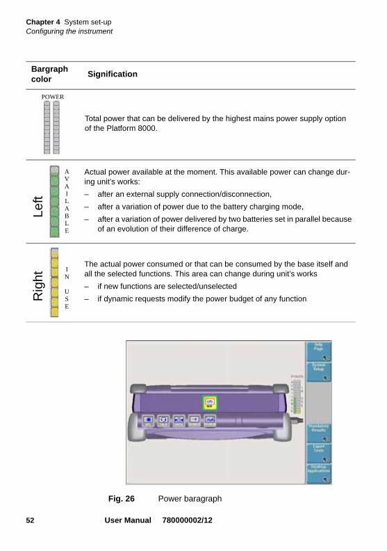
Chapter 4 System set-upConfiguring the instrument
Bargraph color
Signification
Total power that can be delivered by the highest mains power supply option of the Platform 8000.
Actual power available at the moment. This available power can change dur-ing unit’s works:
– after an external supply connection/disconnection,
– after a variation of power due to the battery charging mode,
– after a variation of power delivered by two batteries set in parallel because of an evolution of their difference of charge.
The actual power consumed or that can be consumed by the base itself and all the selected functions. This area can change during unit’s works
– if new functions are selected/unselected
– if dynamic requests modify the power budget of any function
POWER
Fig. 26 Power baragraph
Left
AVAILABLE
Rig
ht
IN
USE
52 User Manual 780000002/12

Chapter 4 System set-upConfiguring the unit
Validatingseveral
simultaneousfunctions
It is possible to validate several distinct functions, whether or not they are elements of the same application1. Thus it is possible, for example, to activate the microscope function at the same time as the OTDR function by validating each of them.
When several functions are validated, pressing the keyboard keys (SETUP, FILE, RESULTS, START/STOP, SCRIPT) will give access to the function in focus (with green round its icon).
To change from one function to another:
– If the functions are elements of the same application (for example, Optical Fibres), simply change tabs (refer to the manual corre-sponding to the application).
– If the functions are not elements of the same application (for example, to change over from the OTDR function to the Transport function), return to the instrument configuration screen shown here and place the focus on the Transport function. The actions of the keyboard keys will then indeed be those corresponding to the Trans-port function.
Help The Help Page of the SYSTEM menu calls up the presentation page of the Platform 8000 (see "Presentation page of the Platform 8000" page 27) and its electronic manual (future function).
Configuring the unitWhen the Platform 8000 is to be used for the first time, or before a measurement campaign is started, the parameters of the system must be configured:
– the parameters specific to the Platform 8000 (screen lighting level, automatic shutdown, validation of SVGA output).
– the parameters specific to the country of use: language, date, time, display format of date and time.
– parameters of input/output.
1.For example, OTDR, OSA and PMD are all elements of the Optical Fibres appli-cation
Use only the direction keys to move the focus on to the desired func-tion. Do not use the validation key, which would have the con-trary effect of de-activating the function.
User Manual 780000002/12 53

Chapter 4 System set-upConfiguring the unit
– activation of loudspeaker and regulation of sound level (with Talkset option)
– programming of automatic shutdown (during battery operation).
– IP adress for upgrading via the network
– parameters for printing
To call up this configuration menu, press the SYSTEM button, then the menu key System Setup.
Factory DefaultConfiguration
Screen
– Darklight: +0
– Contrast: Indoor
– Screen Saver: No
– SVGA output: No
Fig. 27 System configuration screen
NOTE
The key FACTORY DEFAULT allows to reinitialize the configuration set in factory, in case of error during the new configuration.
NOTE
In all the Setup screens, an help is displayed on the bottom right of the screen, concerning the use of direction keys on the Platform 8000.
54 User Manual 780000002/12

Chapter 4 System set-upConfiguring the unit
Country
– Language: English
– Date Format: dd/mm/yyyy
– Time Format: 24 hour clock
– Net Time: None
I/O Interface
– Remote Screen: No
– Ethernet: Config. 1 / Security: Standard
– File Export: None
Utility
– Talkset : Speaker: OnVolume: 4
– VFL Mode: 1 Hz
– Auto off: 30 minutes (only on battery operation)
– Upgrade Parameters: Server address: 172.16.27.18
Printer
– Printer : None
Screen Choosing screen lighting level
In the Screen window, move the cursor on to Lighting.
– use the direction keysorto choose the desired lighting level (between -5 and +5).
or
– click on Edit Number to enter the screen lighting level on the numeric keypad
Contrast
– Indoor: to be selected when the instrument is used inside
– Outdoor: to be selected in order to optimize the readability of the screen for an outside use.
If the Platform 8000 is operating on battery, it is advisable to choose a minimum lighting level acceptable for the user, to keep endurance as long as possible.
User Manual 780000002/12 55

Chapter 4 System set-upConfiguring the unit
Screen saver
This feature is available both when battery powered or AC powered. Its purpose is to extend the life of the screen, in case the Platform 8000 is not used for some time. Instead of the normal screen, a small animated picture of the Platform 8000 is displayed on the blackened screen, even-tually followed from time to time by a name and phone number.
To configure this feature, select Screen Saver.
A sub-menu is displayed :
Screen saver 60s, 3 min, 5 min, No. <No> disables the screensaver. Other values indicate time of inactivitybefore the screen saver automatically starts. Ifthe screen saver is enabled (a time is set), thefollowing two lines are proposed.
Name A name or comment may be entered. This nameor comment may be usefull to persons who findthe Platform 8000 in the screen saver mode.Information such as who currently uses theapparatus, where to find the person or any othercommercial information may be entered.
Fig. 28 Contrast configuration
Fig. 29 Screen saver displaying the factory name
Exemple of inside contrast Exemple of outside contrast
56 User Manual 780000002/12

Chapter 4 System set-upConfiguring the unit
Phone number A phone number or other comment may also beadded in order to provide more information :number to call in case of emergency, usertelephone number...
SVGA output
Information displayed on the screen of the Platform 8000 can be trans-ferred on to an external monitor or projector. To do this:
– connect the monitor or projector to the rear SVGA connector;
– in the Screen window of the configuration menu, move the cursor on to SVGA output and confirm Yes.
Country Choosing language (Language)
Select one of the languages offered, using the direction keys or.
Resetting the date (Date)
Change the date by using the direction keysor
Resetting the time (Time)
– Use the direction keys or to change the minutes and hours
Choosing date and time format
Choose one of the options: dd/mm/yy or mm/dd/yy for the date format.
Use the direction keys or to change the hour format (12 hour clock / 24 hour clock).
Net Time > Sync.
This parameter allows to configure the date and time of the Platform according to a network.
NOTE
This function is deactivated each time the Platform 8000 is switched off.
NOTE
The ENGLISH CAPS parameter allows to get a display in English, with all words in capitals.
User Manual 780000002/12 57

Chapter 4 System set-upConfiguring the unit
– Dynamic Mode: the time is synchronized according to the local network.
The two lines Server Name are displayed but cannot be modified.
– Static Mode: in this case, the time is synchronized to the network server which is defined in the two following parameters.
On the parameter Address Type, select if the address of the server which will be used for synchronization is entered via its IP Address or via the Server Name..
If IP Address is selected, enter one or two server addresses in the following parameters. During synchronization, the first address will always be used, but if a fail occurs, the second one will be used.
If Server Name is selected, enter the name of the server, and if necessary a name for second server. During synchronization, the first server name will always be used, but if a fail occurs, the second one will be used.
During synchronization, the icon displayed next to the time, on the upper banner, is displayed and once the synchronization is valid, the icon becomes .
– None: the time is not synchronized according to a server. In this case, the user can reset date and time himself, using the fields Date and Time.
I/O Interface Remote screen
It is possible to remote the screen of the Platform 8000 on to a PC or on to another Platform 8000 and to read the contents of the disk of the Plat-form 8000 on a PC or on the other Platform 8000. To do this, see ."Accessing the Platform 8000 from a PC" page 39
It is also possible to remote screen of a distant Platform 8000 onto another Platform 8000 and to have full control of the distant instrument. To do this, see "VNC - Remote screen" page 90.
If the network configuration is modified, synchronization may be lost.
NOTE
In Dynamic or Static Mode, the parameters Date and Time are inac-tive.
58 User Manual 780000002/12
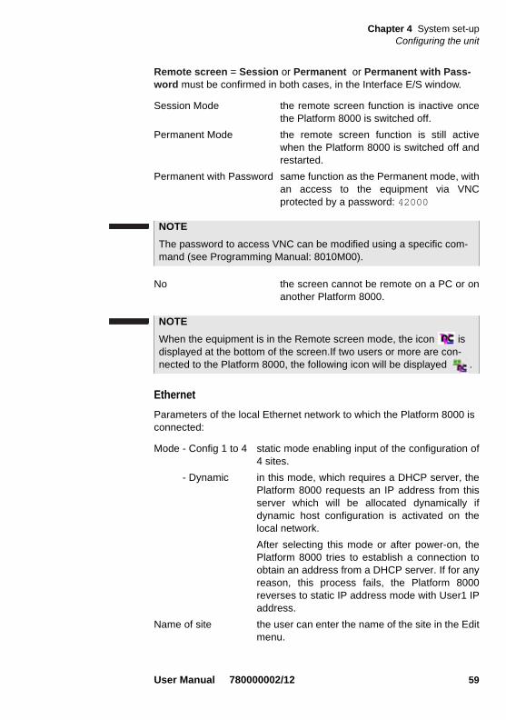
Chapter 4 System set-upConfiguring the unit
Remote screen = Session or Permanent or Permanent with Pass-word must be confirmed in both cases, in the Interface E/S window.
Session Mode the remote screen function is inactive oncethe Platform 8000 is switched off.
Permanent Mode the remote screen function is still activewhen the Platform 8000 is switched off andrestarted.
Permanent with Password same function as the Permanent mode, withan access to the equipment via VNCprotected by a password: 42000
No the screen cannot be remote on a PC or onanother Platform 8000.
Ethernet
Parameters of the local Ethernet network to which the Platform 8000 is connected:
Mode - Config 1 to 4 static mode enabling input of the configuration of4 sites.
- Dynamic in this mode, which requires a DHCP server, thePlatform 8000 requests an IP address from thisserver which will be allocated dynamically ifdynamic host configuration is activated on thelocal network.
After selecting this mode or after power-on, thePlatform 8000 tries to establish a connection toobtain an address from a DHCP server. If for anyreason, this process fails, the Platform 8000reverses to static IP address mode with User1 IPaddress.
Name of site the user can enter the name of the site in the Editmenu.
NOTE
The password to access VNC can be modified using a specific com-mand (see Programming Manual: 8010M00).
NOTE
When the equipment is in the Remote screen mode, the icon is displayed at the bottom of the screen.If two users or more are con-nected to the Platform 8000, the following icon will be displayed .
User Manual 780000002/12 59

Chapter 4 System set-upConfiguring the unit
IP address IP address of the Platform 8000
IP mask address of the mask of the sub-network
IP gateway IP address of the machine enabling accessoutside the sub-network.
DNS2 IP address of the machine providing the IPaddress on the basis of the name
Domain name name of the local network to which the Platform8000 is connected.
Security Standard: with this mode, the software upgradeis enableEnhanced: in this case, no upgrade is possible,all the servers used to upgrade the unit cannotbe started, especially TFTP server. This modeallows to use the Platform 8000 safely, withoutany problem due to the network
Modem (Optional function of the Base Unit)
Parameters for a modem (installed as an option)
Modem Mode May be configured as server or client (client 1, 2,3 or 4).
Modem Tone May be set on on or off, according to your phoneoperator characteristics
Phone Number of the line (with client configuration)
Login Pre-defined as rtu and not modifiable
Password Default password saved by default (not visible)
To validate the new password, you must turn off and disconnect tje Plat-form, plug it back and restart it.
File Export
In the I/O Interfaces menu, select File Export to configure the system in order to send traces and results by e-mail.
Parameters to configure the mail feature.
Send Mail Choose Ethernet if you wish to use the sendingmail function.
Sender Mode Auto or Manual.
In Auto mode, you will not have the possibility toreply to the mail sent.
2.Domain Name Server
60 User Manual 780000002/12

Chapter 4 System set-upConfiguring the unit
In Manual mode, the reply will be sent to theaddress entered in the line From.Use the button
to enter into an edition window
Relay Mode Auto or Manual.
If the e-mail sending is performed via a SMTPnetwork, select the Manual Relay mode andindicate the SMTP server address in the fieldMail Relay, using the button to open theedition window.
In Auto mode, the sending of e-mail is performedautomatically.
See "Send by mail" page 120 for more explanation on sending files.
Utilities Talkset
Parameters to use when the instrument is equipped with the talkset option (see "«Talkset» optical telephone function" page 87).
All Platform 8000 are equipped with a loud speaker as standard. Some are also equipped with an integral microphone.
When no internal microphone is present, this option is used to set the loud speaker to On or Off.
Platform 8000 equipped with an internal microphone offer a conference mode on this line. This mode may be set as:
– Speaker and Micro off
– Speaker only
– Speaker and Micro on
When you are in conference mode, you don’t need the headphone supplied with the talkset option to hear and talk hands free to the user of the remote instrument.
Another line is used in both cases to set the volume level. The same setting is used for headphone, headphone microphone, loud speaker and internal microphone, if any.
Use the direction keys or the numeric keypad to change the volume level (Min = 0 / Max = 7).
If Sender Mode is set to Auto, any reply to an e-mail sent by the Plat-form 8000 will be lost.
User Manual 780000002/12 61
Chapter 4 System set-upConfiguring the unit
VFL Mode
Select the mode of emission of the light signal:
– 1 Hz: frequency of 1Hz (blinking signal)
– CW: signal is emitted in a Continuous Wave
Automatic shutdown
This function switches off the Platform 8000 automatically if no operation has been performed and no key actuated for a period selected from this menu. Work in progress is automatically saved.
– To activate this function, open the Utilities window and move the cursor on to Auto off, then choose an option (5, 10 or 15 min.) so that the Platform 8000 will be automatically switched off if no key has been actuated for the period selected.
– To deselect this function go into the Utilities window, move the cursor on to Auto Stop, then choose option No.
Update
When updating the software, (see "Installing a new version of the soft-ware" page 126), in the Server Address line of the configuration menu > Upgrade Parameters, enter the IP address of the PC on which the updating files were loaded.
Printer Parameters for configuring an internal printer, a USB printer or for saving JPG files.
Printer None, internal, internal compressed , USB, Files(Formatted), Files (Screen).
If you choose USB, you can configure themanufacturer and model type of the printer to beconnected on the next two lines. The parameterUSB Land allows to configure the printer as the USBparameter, but also to print with landscape setting.
If you select Internal or Internal compressed, youdon’t need to select the printer manufacturer or theprinter type.
NOTE
The function for automatically switching off the Platform 8000 is avail-able only on battery operation, to save the battery.
62 User Manual 780000002/12

Chapter 4 System set-upConfiguring the unit
Files (Formatted or Screen): allows to print to theJPG format
Files (Formatted) Choosing in the Printer menu, the option Files (Formatted), you can print the open file of the Platform 8000 in the JPG format, exactely as if the file was printed on paper. Therefore, if the file (trace or other) is too large for one A4 page, several JPG files will be created.
Printing a trace to the JPG format
Once the Files (Formatted) function is selected:
1 Open the trace to be printed in the JPG format
2 If necessary, make the modifications on the trace (see user manual of the 8100 series).
3 Set the trace view as wished:
– if the function is set to the Trace mode (Trace is selected on the menu key Trace/Table/Summary), the JPG file will countain the header and the trace (in one page).
– If the function is set to Table mode (Table is selected on the menu key Trace/Table/Summary), the JPG file will countain the header, the trace and the entire results table (several pages may be required)
– If the function is set to Summary mode (Summary is selected on the menu key Trace/Table/Summary), the JPG file will coun-tain the header and the summary page. This view is only avail-able with OTDR traces.
4 Press the PRINT key
The icon is displayed until the saving process is finished
5 Press the FILE key to find the JPG file in the Explorer
NOTE
Internal and Internal compressed refer to the same internal printer but modifies the way this printer prints. While the first one prints side-ways in a landscape mode, the second one prints straight forwards, and therefore provides a smaller «compressed» picture.
NOTE
The JPG file will be saved in the current directory, the last directory used.
User Manual 780000002/12 63

Chapter 4 System set-upConfiguring the unit
The name of the JPG file will be: name of the stored trace_date (year/month/day)_time (hour/minute/second).jpg
Printing another file to the JPG format
Once the Files (Formatted) function is selected:
1 Open the file to be printed in the JPG format (for example: Micro-scope etc.)
2 Press the PRINT key
The icon is displayed until the saving process is finished
3 Press the FILE key to find the JPG file in the Explorer
The name of the JPG file will be: Print_date (year/month/day)_time (hour/minut/second).jpg
Files (Screen) Choosing in the Printer menu, the option Files (Screen), you can print the open file of the Platform 8000 in the JPG format, exactely as it is displayed on the screen.
Therefore, if you make a zoom on the trace for example, the JPG file will only show the zoom section.
Once the Files (Screen) function is selected:
1 Open the trace or file to be printed in the JPG format.
2 Make the necessary modifications
3 Press the PRINT key
The icon is displayed until the saving process is finished
4 Press the FILE key to find the JPG file in the Explorer
The name of the JPG file will be: Print_date (year/month/day)_time (hour/minut/second).jpg wether it is a trace file or not.
NOTE
The JPG file will be saved in the directory PRINT, on the harddisk of the Platform 8000.
NOTE
The JPG file will be saved in the directory PRINT, on the harddisk of the Platform 8000.
64 User Manual 780000002/12

Chapter 4 System set-upStandalone results
Printer manufacturer Use the keys and to select themanufacturer corresponding to the printer youwish to configure. By default, a model type willautomatically be proposed on the next line,corresponding to your manufacturer choice.
Printer type If the model type set by default for the chosenmanufacturer is not correct, you may change itusing the keys and .
ASCII Mode Select Graphic or Text according to the printerconfiguration. Some printers do not recognize theASCII mode, so that you must select Graphic toprint files from the Web Browser.
Standalone resultsEven if no module is present, the Platform 8000 can access and display measurement results.
To access this feature, select Standalone Results, and choose the desired application, for example Consult Fiber Optics.
Expert Tools
SoftwareUpgrade
The Software Upgrade key allows to make an upgrading of the softwares (see “Installing a new version of the software” on page 126)
Remote Display The Remote Display menu allows to remote the screen of the Platform 8000 to a PC or to another Platform 8000 (see "«Talkset» optical tele-phone function" page 87)
Media utilities To get access to the menu, click on Expert tools then on Media utilities.
Formating a USBmemory stick
In order to format a USB memory stick, select Media utilities, then Usbflash Format. Confirm your choice to actually format the USB memory stick.
User Manual 780000002/12 65

Chapter 4 System set-upExpert Tools
Formatting aCompactFlash
card
– In order to format a CompactFlash card, select Media utilities then CF Format.
– Confirm your choice to actually format the CompactFlash card.
– Enter the password 20876 to start CompactFalsh card formating.
Formatting a CD In order to format a CD, select Media utilities, then Erase CD. Confirm your choice to actually format the CD.
Removing the USBmemory stick
Once a USB memory stick is inserted in one of the USB port of the 8000 Platform: it can be removed via the Media Utilities menu.
1 Click on Expert Tools > Media Utilities
2 Push the Eject USB key,
The icon becomes to indicate it can be removed safely. In this case, the USB stick cannot be used anymore
USB memory sticks can be very different.
They differ on Hw and Sw aspects, even inside a given brand.
In particular, USB memory sticks targeting audio recording are often formatted in very specific ways and the format is often very different from a standard FAT.
For all these reasons, we advise users to use memory sticks provided by JDSU.
In any case, USB memory sticks which are recognized by the MTS (a beep is generated when plugged on the MTS) but which cannot be read or written, should be formatted on the MTS with the Usbflash Format utility in Expert tools > Media utilities.
If a problem occurs with the USB stick you are using, contact your Local Technical Assistance Center.
As for any media formatting, please note that all data present on the USB memory stick will be irremediably lost.
As for any media formatting, please note that all data present on the USB memory stick, the CompactFlash card or the CD will be irremedi-ably lost
66 User Manual 780000002/12

Chapter 4 System set-upExpert Tools
The USB memory stick can then be disconnected from the Platform 8000's USB port.
The disconnection of the USB memory stick produces one beep.
Erase disk The key Erase disk, in the Expert Tools > Media Utilities menu, allows to erase all the contents of the harddisk set into the Platform.
Locking thePlatform 8000
The Platform 8000 can be locked at any time:
1 In the SYSTEM page, click on Expert Tools
2 Click on Instrument Lock Out
3 Confirm the Platform 8000 locking by clicking on Confirm (or use the Cancel key to cancel the process).
The numeric keypad is displayed
4 Entrer the password to lock the instrument: 42000 (see "Example of Edit menu" page 36)
5 Click on Validate
The Platform 8000 locking screen is displayed.
NOTE
The USB memory stick can also be removed via the File menu (see “External USB storage media” on page 111).
Fig. 30 Password
User Manual 780000002/12 67

Chapter 4 System set-upDesktop Applications
Click on the Notepad Message key to add a message using the text edition (see "Example of Edit menu" page 36).
Unlocking the Platform 8000
– Once the locking screen is displayed, click on the key Unlock Instrument.
– Enter the password 42000 using the numeric keypad (see "Numeric Keypad" page 38) and validate.
The sceen automatically displays the SYSTEM page.
Desktop ApplicationsSeveral desktop applications are available with the Platform 8000.
To have more information about this function, see Chapter 8 “Desktop applications” page 103.
Fig. 31 Locking screen
68 User Manual 780000002/12
Chapter 5 LTS (Loss Test Set)
5
A variety of LTS options are available when ordering. Option 80/PM consists of a power meter only. The other options in the 80XXTS/PM series combine optical telephone, power meter and one or more sources of various wavelengths. See references in "References of options for the Platform 8000 mainframe" page 148, for wavelengths of the sources in each option.The topics discussed in this chapter are as follows:
– “The principle of optical power and attenuation measurements” on page 70
– “Connection to the power meter and the source” on page 71
– “Configuring the LTS” on page 72
– “Display of results and commands” on page 75
– “Making a measurement” on page 77
– “Performing an ORL Manual measurement with the Platform 8000” on page 79
– “Storing and reloading LTS results” on page 83
User Manual 780000002/12 69

Chapter 5 LTS (Loss Test Set)The principle of optical power and attenuation measurements
The principle of optical power and attenuation measurements
Powermeasurements
A power meter, is all that is needed to measure emitted or received power:
– to measure emitted power, connect the power meter directly to the output of the optical emitter;
– to measure the power at the input of an optical receiver, the power meter is connected to the end of the fiber, at the point where the optical receiver would be connected.
Attenuationmeasurements
(optical linkloss)
For measurement of the attenuation of power in a complete link or in elements such as sections of fiber, connections or optical components, a light source and a power meter are required.
This attenuation is usually deduced from the measurement of optical power at two points:
Attenuation A(dB) = P1 (dBm) - P2 (dBm)
To perform accurate measurements, the following conditions are vital
– Use one of the light sources of the LTS or a light source which is stable both in time and as a function of temperature.
– Make sure that all connections and fibers and the receiving cell are perfectly clean.
– Use a reference link between the laser source and the test subject. If several measurements are to be made under identical light injec-tion conditions, this reference fiber must not be disconnected during the period while measurements are taking place.
Insertion loss method
1 The power meter is first connected to the laser source via the refer-ence fiber: P1 is measured.
2 Then the fiber to be tested is inserted between the reference fiber and the power meter: P2 is measured.
Laser light source of the Platform 8000 Reference
fiberLink under test
Power meter of the Platform
1 2
70 User Manual 780000002/12

Chapter 5 LTS (Loss Test Set)Connection to the power meter and the source
The difference between P2 and P1 gives the attenuation of the fiber under test.
It is preferable to use the same type of connector at both ends of the fiber being tested, to ensure the same connection conditions for measuring P1 and P2.
Accuracy of measurements
– A high degree of accuracy is often required. It is then necessary to perform a preliminary calibration without the fiber under test to elim-inate the losses due to connections as far as this is possible. To do this, use the «Reference Value» function.
– For measurements in the laboratory, where both ends of the fiber are on the same site, the repeatability of attenuation measurements is better than 0.1 dB. For measurements in the field, where the two ends are on different sites, variations from one measurement to another are of the order of ± 0.2 dB (using a relative measurement).
Connection to the power meter and the source
The type of optical connector used for the power meter is UPP (Universal Push Pull), which is compatible with all diameter 2.5 mm connectors (FC, SC, ST, DIN, E2000, etc.)
If the source option is present, the source connection is the same as that for the talkset.
Fig. 32 Optical connectors
Power meter optical connection
Optical connector of one of the sources
User Manual 780000002/12 71

Chapter 5 LTS (Loss Test Set)Configuring the LTS
Configuring the LTSThe LTS function is an option chosen at the time of order and incorpo-rated into the Platform 8000 in the factory.
To activate the function:
– Press the SYSTEM button
– Use direction keys to select the Power Meter or Source icon (framed in green) and press : the icon in the frame will turn yellow.
The effect of this action will to be to bring the power meter / source into use.
Configuring themeasurementparameters of
the powermeter
The measurement parameters can be accessed with the SETUP key once the icon .is selected.
Lambda Selecting wavelength:- Auto: the wavelength of the input signal will beautomatically detected and selected to performthe measurement:850, 980, 1300, 1310, 1420, 1450, 1480, 1490,1510, 1550 or 1625 nm: measurement performedat specified wavelength.- User: choice of wavelength on the next line inthe menu.
User choice (if the User option was selected in the Lambdaline) selection of the wavelength between 800nm and 1650 nm, in 1 nm steps, by means of thedirection keys and .
Beep on modulation Select if a sound must be emitted on modulationor not (Yes / No)
Unit Unit of power displayed:
- Watt, dBm for displaying absolute power
Fig. 33 Configuration of power measurement
72 User Manual 780000002/12

Chapter 5 LTS (Loss Test Set)Configuring the LTS
- dB for displaying a result relative to a reference(link loss)
Reference level If dB units were chosen in the previous line,selection of the reference value for thewavelength selected. Using the direction keys,first choose the wavelength, then press the > keyto access choice of the value (+XXX.XX), thenconfirm this value with the validation key .
This reference is also automatically available, inthe Results page, using the Set as Referencekey.
Attenuator compensationChoice of level to be applied to the wavelengthchosen for measurement to compensate for theloss due to the external attenuator (+XX.XX dB).First use the direction keys to choose thewavelength, then press > to access choice ofvalue, then confirm this value by pressing thevalidation key .
Configuring thealarm
parameters ofthe power
meter
Alarm Activation of the Alarm function : any result belowthe lower threshold or above the upper thresholdwill be displayed in red on the Results page.
Lower and upper thresholds :
Choice of lower and upper thresholds for eachavailable wavelength, from -60 to +40 dBm(selected with the direction keys).
NOTE
To copy a Reference Level or a Attenuator Compensator on all wave-lengths, select the reference wavelength and click on Update for All Wavel..
NOTE
To copy one value of the Lower or/and Upper threshold for all wave-lengths, select the reference value and click on Update for All Wavel..
NOTE
A continuous push on the direction keys, increments the value by 10 dBm.
User Manual 780000002/12 73

Chapter 5 LTS (Loss Test Set)Configuring the LTS
Configuringand displayingthe parameters
of the source
On the System page, select the Source icon and press RESULTS hardkey.
The following page displays
Laser Activation or shut-down of the laser (samefunction as the START/STOP button)
When the laser is on, the icon is displayed.
The parameters of the source can be accessed directly on the result screen of the LTS module, by pressing the Source Configuration soft key.
Wavelength To change the wavelength when a multi-wavelength source is present (depending onoption).
The wavelength value is displayed.
Mode To vary the mode of emission of the source.Possible modulation values are:
– 270 Hz
– 330 Hz
– 1 kHz
– 2 kHz
– Auto (the sources emit on determined frequencies to enable the power meter to detect the wavelength used automatically)
Fig. 34 Configuration of the source
74 User Manual 780000002/12

Chapter 5 LTS (Loss Test Set)Display of results and commands
– TwinTest (cyclical emission on all available wavelengths for a few seconds on each wavelength), compatible with the JDSU OLP 5/6/15/16/18.
– CW (continuous emission)
The mode used is displayed, above the icon .
Source Reference This key allows to display two other soft keys:
Standard Ref: select the current result as reference value to measure the attenuation of a link. This reference is displayed under the measurement result until a new reference value is chosen..
Jumper Ref: this key allows to perform a measurement in loopback mode using the power meter on Base-Unit and a Source on the OTDR Module onto this Base Unit (see user manual of the Module 8100 Series).
Display of results and commandsThe results page called up by the RESULTS button, gives the information relating to the measurement in progress, results previously saved and the commands available for measurement and saving.
Result of themeasurement in
progress
The power measured by the power meter is displayed in large charac-ters, in the units selected in the SETUP menu, together with:
– the mode of transmission of the signal measured: continuous (CW) or modulated to a frequency of 270Hz, 330Hz, 1KHz, or 2KHz.
– the wavelength of the signal measured.
– the reference level expressed in dB.
– the level of Attenuation Compensation.
NOTE
The soft key Jumper Ref is displayed in grey and cannotbe activated if both power meter and Source are selected onto the Base-Unit. The power meter must be selected onto the Base-Unit, and the Source onto the OTDR Module to activate the soft key and to be able to per-form a reference measurement in loopback mode.
User Manual 780000002/12 75

Chapter 5 LTS (Loss Test Set)Display of results and commands
Table of results For one and the same fiber, the power meter displays a table of 9 results corresponding to the different possible wavelengths. The table shows the power measured in dBm, the relative power (in dB) and the reference level in dBm (if units = dB), together with the mode.
A measurement result is displayed in the table when the Keep Result softkey is pressed.
The Clear Table softkey orders deletion of all the results displayed in the table.
If the Alarm function has been activated, any result that exceeds the selected thresholds appears in red in the table. Otherwise, results are shown in the table in green.
When the instrument is switched off, results present in the table are saved.
Commands ofthe power
meterparameters
When the LTS function is selected, the following softkeys are available on the results page:
Keep Result Saves the result on the corresponding line of thetable.
Clear Table Deletes all the results recorded in the table.
Pressing the Powermeter Config. key allows to reach the following function:
Fig. 35 Results and commands of the power meter
Resultsof thepower meter
76 User Manual 780000002/12

Chapter 5 LTS (Loss Test Set)Making a measurement
Wavelength Allows to modify the wavelength to be appliedwith the Power meter.
Unit Allows to modify the unit of power displayed (dB,dBm, nW)
Zero Adjustment of the Zero value when the powermeter’s optical input is closed with a plug (avalidation is required).
Click on Exit to go back to the Results page.
Pressing the Pow. Reference key allows to reach the following function:
Standard Ref. Selects the current result as reference value tomeasure the attenuation of a link. This referenceis displayed under the measurement result until anew reference value is chosen.
Jumper Reference This key can be pressed when a reference inloopback mode must be performed (see 8100Module Series User Manual)
Making a measurementThe power meter is started up as soon as the Power icon is acti-vated in the System page.
If a Platform 8000 source is used, the START/STOP key or the Laser on/Laser off soft key must be used to start or stop emission of light.
Powermeasurement
– Connect the light source to be tested to the rear connector (see "Connection to the power meter and the source" page 71).
– In the SETUP menu, choose the units dBm, dB or Watts.
– Press the START/STOP key to start the laser.
The soft key Jumper Ref is displayed in grey and cannot be activated if both Power meter and Source are selected onto the Base-Unit. The power meter must be selected onto the Base-Unit, and the Source onto the OTDR Module to activate the soft key and to be able to perform a reference measurement in loopback mode.
Power measurement is automatically updated in consequence. The value «<-60 dB» is displayed when the laser is switched off and if the source output is looped on to the power meter input.
User Manual 780000002/12 77

Chapter 5 LTS (Loss Test Set)Making a measurement
The result will appear in the results page and can be memorized in the table (see "Table of results" page 76).
– Press the START/STOP key to stop the laser.
Optical link loss
Setting the zerovalue of the power
meter
1 Fix the plug over the optical input of the power meter so that no light can reach the photodiode of the power meter. If the zero adjustment is made without this plug, an error message may be displayed, as the photodiode will detect too much light.
2 In the Results page, press Powermeter Config. > Zero soft keys and validate.
Carrying out thereference
measurement
1 Fix the adapter corresponding to the jumper to the optical connector of the power meter.
2 Connect the jumper between the input of the power meter and the output of the source.
3 Configure the same wavelength on the source and the power meter.
The power measured is displayed in the results page of the LTS.
4 Press the Power Reference > Standard Ref. soft key to save the result displayed as reference value.
Measurements onthe fiber under test
After defining the reference value, proceed as follows to make the measurement:
1 Fix the jumpers and connectors needed to connect the fiber to be tested between the source output and the power meter input.
2 In the set-up menu, select dB units.
3 The power displayed in the Power Meter window corresponds to the optical loss of the link tested. It can be displayed in the table (see "Table of results" page 76).
It is important to set the zero of the power meter before making any measurements where accuracy is required, as the noise from the ger-manium photodiode fluctuates over time and with variations in tem-perature.
78 User Manual 780000002/12

Chapter 5 LTS (Loss Test Set)Performing an ORL Manual measurement with the Platform 8000
Performing an ORL Manual measurement with the Platform 8000
Using simultaneously the powermeter and talkset ports on the Base Unit allows to perform an ORL manual measurement.
In the System page, select the icon ORL of the Base Unit.
Establishing areference for an
ORL manualmeasurement
Two steps must be carried out to take a reference for an ORL manual measurement:
1 Power emitted reference
2 Zero ORL adjustment
ORL Emittedpower
1 Once the ORL icon is selected, click on RESULT hardkey
The ORL page opens
It is not possible to use the source at the same time than the Talkset option or the Data Transfer.
Follow the order given above to take the reference. They are not two different processes but two steps necessary to establish a reference for an ORL measurement
User Manual 780000002/12 79

Chapter 5 LTS (Loss Test Set)Performing an ORL Manual measurement with the Platform 8000
2 Click on Zero key
The message Put caps on the powermeter port then confirm displays: click on Yes to validated and wait for the second message, Dark current calibration completed then hit on any key to continue the process.
3 Click on ORL Power Emitted key
4 Follow the instruction on the upper part of the screen: connect the jumper from the talkset port to the powermeter one.
5 Click on Go
6 The message Measurement in progress... is displayed.
7 Once completed, the results for ORL Power Emitted are displayed for each wavelength.
Fig. 36 ORL page
80 User Manual 780000002/12

Chapter 5 LTS (Loss Test Set)Performing an ORL Manual measurement with the Platform 8000
8 Click on Exit to go back to the initial screen in order to perform the ORL Zero measurement
Once the reference has been taken, the reference screen is updated for the wavelengths available.
As the Zero mesurement has not yet been done, the first line of the table displays the message Ref ORL : Incomplete.
ORL Zeroadjustment
Once the Power Emitted measurement has been carried out, the Zero adjustment can be performed:
1 Click on ORL Zero
2 Follow the instructions displayed at the top of the screen: disconnect the jumper from the power meter port and wrap this jumper, still connected to the talkset port, around the mandrel (6 to 7 times).
3 Push the Go key
4 Once completed, the results displayed in the column Zero ORL.
Fig. 37 Power Emitted result
ORL Zero cannot be performed on a bend insensitive fiber.
User Manual 780000002/12 81

Chapter 5 LTS (Loss Test Set)Performing an ORL Manual measurement with the Platform 8000
Once the reference has been taken, the reference screen is updated for the wavelengths available. It indicates the type of refer-ence used.
Measurementacquisition
Before making an ORL manual measurement, check that:
– each end of the fiber is correctly connected to the module.
– the fiber and jumpers are in good condition.
To display the fiber measurement page, push the START/STOP key.
Fig. 38 Results table with ORL Power emitted and Zero ORL for each wavelength
Once the two references are complete, the date as well as the type and serial number of the local instrument are displayed on the first line of the table.
If not, the message Ref ORL : Incomplete is displayed.
82 User Manual 780000002/12
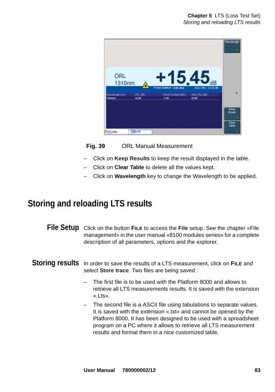
Chapter 5 LTS (Loss Test Set)Storing and reloading LTS results
– Click on Keep Results to keep the result displayed in the table.
– Click on Clear Table to delete all the values kept.
– Click on Wavelength key to change the Wavelength to be applied.
Storing and reloading LTS results
File Setup Click on the button FILE to access the File setup. See the chapter «File management» in the user manual «8100 modules series» for a complete description of all parameters, options and the explorer.
Storing results In order to save the results of a LTS measurement, click on FILE and select Store trace. Two files are being saved :
– The first file is to be used with the Platform 8000 and allows to retrieve all LTS measurements results. It is saved with the extension «.Lts».
– The second file is a ASCII file using tabulations to separate values. It is saved with the extension «.txt» and cannot be opened by the Platform 8000. It has been designed to be used with a spreadsheet program on a PC where it allows to retrieve all LTS measurement results and format them in a nice customized table.
Fig. 39 ORL Manual Measurement
User Manual 780000002/12 83

Chapter 5 LTS (Loss Test Set)Storing and reloading LTS results
Loading results In order to load the results of a LTS measurement, select a file with the extension «.Lts» in the file explorer (see the chapter «File manage-ment» in the user manual for «8100 modules series»), click on Load then View trace.
The LTS tab is displayed with the loaded results in the table.
84 User Manual 780000002/12

Chapter 6 VFL, Talkset and Data transfer
6
The VFL and Talkset functions of the Platform 8000 described in this chapter are basic options installed in the factory.The topics discussed in this chapter are as follows:
– “VFL and Talkset connectors” on page 86
– “Visible source function (VFL)” on page 86
– “«Talkset» optical telephone function” on page 87
– “«Data», the data transfer function” on page 88
– “VNC - Remote screen” on page 90
User Manual 780000002/12 85

Chapter 6 VFL, Talkset and Data transferVFL and Talkset connectors
VFL and Talkset connectors
Talksetconnectors
These connectors, together with the connector of the Power Meter option, are located at the rear under a protective flap.
To change the adapter situated on the optical connector of the talkset, pull the lever shown above.
To put the adapter back, engage it in the optical connector and push in, pressing on the connector and not on the lever, so that the lateral lugs of the connector engage in the notches of the adapter. Then press the connector lever to lock it.
VFL connector The type of optical connector used for the VFL source is UPP (Universal Push Pull), which is compatible with all diameter 2.5 mm connectors (FC, SC, ST, DIN, E2000, etc.)
Visible source function (VFL)This function is used to emit a red light signal of frequency 1 Hz or in continuous mode into a fiber to detect any defects in the dead zone of the reflectometer, or to identify it.
This function is suitable for short fibers (length < 5 km) or for the first few metres of a long fiber.
Fig. 40 Connectors
Talkset VFL
Adapter release lever.
Power MeterTalkset headset
86 User Manual 780000002/12

Chapter 6 VFL, Talkset and Data transfer«Talkset» optical telephone function
To emit a light signal into a fiber:
– Connect the fiber to the VFL port on the rear panel (see above)
– Press the SYSTEM key, then press <- and -> to select the VFL icon and confirm by pressing the validation key .
– You can configure the signal mode in the System Setup page > Utility > VFL Mode (see “VFL Mode” on page 62).
Selection of this option is compatible with another function (OTDR, etc.).
«Talkset» optical telephone functionThis enables two operators at opposite ends of an optical link to commu-nicate along the fiber. Each end of the optical link must be provided with a Platform 8000 equipped with the Talkset option (or with a Platform 8000 together with an OFI 2000 equipped with the Talkset option).
Talkset configuration
The talkset configuration is set in the setup screen (see "Talkset" page 61)
Connections
At each end of the fiber (see "VFL and Talkset connectors" page 86):
– Connect the fiber to the Talkset port of the Platform 8000, either directly or through jumpers.
– A headset (with earphones and a microphone) supplied with the option may also be plugged into the talkset module jack.
Establishing communication
On the caller Platform 8000, press the SYSTEM button, then select and confirm the Talkset option:
NOTE
Identification is facilitated by the blinking of light in the fibre.
NOTE
It is possible to use the optical telephone of the Platform 8000 and to carry out measurements at the same time.
User Manual 780000002/12 87

Chapter 6 VFL, Talkset and Data transfer«Data», the data transfer function
– If the remote instrument is ready to receive (on standby), the Talkset icon turns orange, beeps are emitted, and the icon appears at the top of the screen: telephone communication can now take place.
– If the remote instrument is not ready to receive, the Talkset icon does not change color and a message is emitted.
Adjusting volume level
The sound is transmitted to the earphones of the headset and, if this function has been activated, to the speaker in the Platform 8000 base. To activate the base loudspeaker and adjust the volume:
– press the SETUP key.
– under the Utilities heading of the menu, select the Talkset line: it is then possible to activate the base loudspeaker and adjust the volume.
When communication is over, deactivate the Talkset function on the Platform 8000. This deactivation can be done by either Platform 8000.
«Data», the data transfer functionThis enables two Platform 8000 at opposite ends of an optical link to transfer data along the fiber.
NOTE
The talkset icon is displayed on the top banner as long as communi-cation remains established, letting the user know that the connection is working
When communication is established, the headset is automatically enabled if plugged in. However, the loud speaker and internal micro-phone must be correctly configured in the setup menu to work accord-ingly (see "Talkset" page 61 )
NOTE
Each end of the optical link must be provided with an Platform 8000 equipped with the Talkset option.
NOTE
It is possible to use the Data transfer feature while using the optical telephone of the Platform 8000. Nevertheless, the data transfer speed will be slightly decreased.
88 User Manual 780000002/12

Chapter 6 VFL, Talkset and Data transfer«Data», the data transfer function
Data transfer configuration
No specific data transfer configuration is necessary
Connections
At each end of the fiber (see "VFL and Talkset connectors" page 86):
– Connect the fiber to the Talkset port of the Platform 8000, either directly or through jumpers.
Data transfer uses the same fiber as the optical telephone.
Establishing communication
On the caller Platform 8000, press the SYSTEM button, then select and confirm the Talkset option:
– If the remote instrument is ready to receive (on standby), the Data icon turns orange, beeps are emitted, and the icon appears at the top of the screen: data transfer can now take place.
– If the remote instrument is not ready to receive, the Data icon does not change color and a message is emitted.
To end the communication, deactivate the Data function on one of the Platform 8000 (the local or the remote one).
Fig. 41 Active communications appear in yellow
NOTE
Data transfer varies according to the type of application you use. For Fiber Optics for example, you can use the explorer. The distant Plat-form 8000 will be shown just like a disk and all file and directory fea-tures can be used from and to that disk.
NOTE
The data icon is displayed on the top banner as long as communica-tion remains established, letting the user know that the connection is working
User Manual 780000002/12 89

Chapter 6 VFL, Talkset and Data transferVNC - Remote screen
VNC - Remote screenThis enables an operator at one end of an optical link to take control over another Platform 8000 connected at the other end, using the fiber.
VNC configuration
Before it can be remote-controlled, the Platform 8000 must be configured as explained in "Remote screen" page 58.
Connections
At each end of the fiber (see "VFL and Talkset connectors" page 86): connect the fiber to the Talkset port of the Platform 8000, either directly or through jumpers.
Remote screen via VNC is done via the data transfer feature, and on the same fiber as the optical telephone.
Establishing communication
On the caller Platform 8000, press the SYSTEM button, then select and confirm the Talkset option:
– If the remote instrument is ready to receive (on standby), the Data icon turns orange, beeps are emitted, and the icon appears at the top of the screen: data transfer can now take place.
– If the remote instrument is not ready to receive, the Data icon does not change color and a message is emitted.
– Click next on Expert tools, Remote Display, and on Switch to remote screen.
Your screen is now fully replaced by the distant screen, and everything you do on your Platform 8000 is in fact done on the distant Platform 8000.
An icon appears in the top banner of the Platform 8000.
NOTE
Whoever begins the communication, data transfer may be done bidi-rectionally in the exact same manner.
NOTE
Each end of the optical link must be provided with a Platform 8000 equipped with the Talkset option.
90 User Manual 780000002/12

Chapter 6 VFL, Talkset and Data transferVNC - Remote screen
End of a VNC session
In order to end a VNC session, you can :
– Return to the menu Expert tools > Remote Display and click on Return to local screen. (Recommended solution)
– Deactivate the data function on either Platform 8000 connected.
– Set Remote screen to off (see “Remote screen” on page 58)
– Disconnect the fiber
A slight normal color degradation may be seen on the Platform 8000 controlling a distant instrument.
NOTE
The VNC icon in the top banner of the screen lets you know at all times whether you are in a VNC session or not.
User Manual 780000002/12 91

Chapter 6 VFL, Talkset and Data transferVNC - Remote screen
92 User Manual 780000002/12

Chapter 7 Scope
7
The scope function is a hot-plug feature enabled directly when inserting a USB scope supplied as an accessory (see"References of scopes and associated accessories" on page 151 ).The topics discussed in this chapter are as follows:
– "Scope feature" on page 94
– "Scope connection" on page 94
– "Result display" on page 95
– "File toolbar" on page 98
– "Mosaic Mode" on page 99
User Manual 780000002/12 93
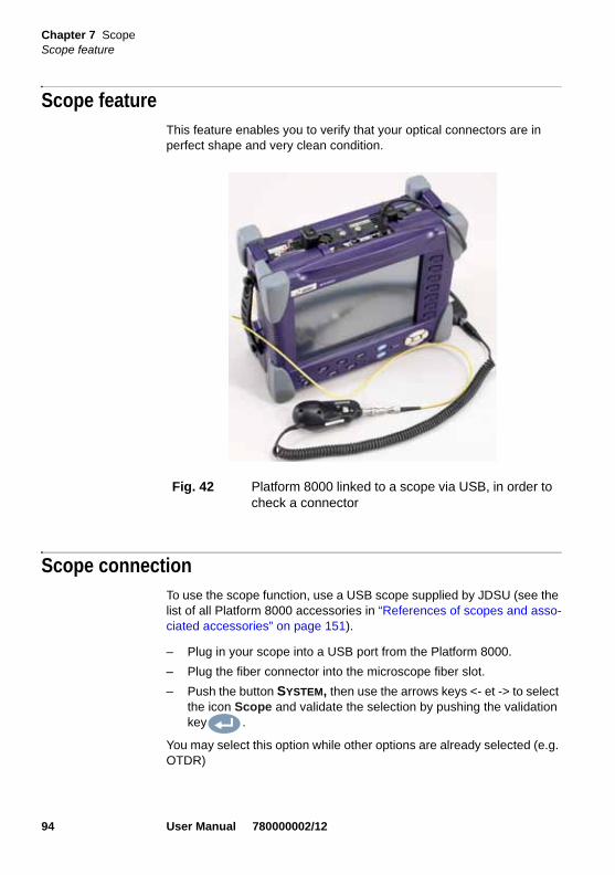
Chapter 7 ScopeScope feature
Scope featureThis feature enables you to verify that your optical connectors are in perfect shape and very clean condition.
Scope connectionTo use the scope function, use a USB scope supplied by JDSU (see the list of all Platform 8000 accessories in “References of scopes and asso-ciated accessories” on page 151).
– Plug in your scope into a USB port from the Platform 8000.
– Plug the fiber connector into the microscope fiber slot.
– Push the button SYSTEM, then use the arrows keys <- et -> to select the icon Scope and validate the selection by pushing the validation key .
You may select this option while other options are already selected (e.g. OTDR)
Fig. 42 Platform 8000 linked to a scope via USB, in order to check a connector
94 User Manual 780000002/12

Chapter 7 ScopeResult display
Result displayTo display the result, click on RESULTS while Scope is still actively selected.
Camera mode Set the key Camera/Freeze on Camera, to get a live picture of the scope result.
Luminosity and contrast settings
Luminosity and contrast may be set manually by using the key Bright/Cont.. Once you select which parameter you wish to modify, use the arrow keys and to tune the luminosity or contrast to the desired value. Note that the set values are displayed on the key.
You may also choose to use the function Auto Contrast in order to get settings calculated automatically by the instru-ment.
Fig. 43 Selection of the Scope icon to use the scope
In order to see the Scope icon and select it, you must first make sure that the scope is correctly plugged into an available USB slot, before you reach this screen. If this was not done, quit this screen and come back to it after plugging in your scope correctly. This will refresh your detected devices.
Use the scope wheel to tune the sharpness of the picture.
User Manual 780000002/12 95

Chapter 7 ScopeResult display
Freeze mode Once the result is acceptable (sharpness, luminosity and contrast are tuned correctly), you may freeze the picture. This feature allows to store in memory the resulting picture in order later to compare it to others or save it in a file.
NOTE
Saturated parts of the picture appear in yellow. Modify the luminosity and contrast settings or use Auto contrast to modify the actual set-ting and remove saturation.
Fig. 44 Example of the result you get using the scope option on a connector in perfect condition
Freezing a scope result does not store the picture in a file (see "Sav-ing a picture" on page 98). The result will be lost if the instrument is shut off, or if more than 3 pictures are frozen (see "Mosaic Mode" on page 99).
96 User Manual 780000002/12

Chapter 7 ScopeResult display
Adding a comment
A key Comment allows you to enter a comment to your picture if neces-sary. This comment appears at the bottom left of the picture.
The right bottom of the frozen picture also contains the date of the acqui-sition (where the picture was frozen).
NOTE
The button set on the lead allows to freeze the picture or to take a snapshot.
NOTE
Both the comment and the date will be saved with the picture if that picture is saved later on.
NOTE
The comment may be modified at any time later on.
Fig. 45 Frozen Scope image
Comment Date of acquisition
User Manual 780000002/12 97

Chapter 7 ScopeFile toolbar
File toolbarClick on the FILE button to access the File toolbar on the right of the screen.
Saving apicture
It is possible to save the frozen picture resulting from the scope.
To do this, select Save. An edition screen is displayed in which to enter alphanumerical characters in order to save the file with an appropriate name.
Loading apicture
It is possible to retrieve and load a picture stored in the default directory (see "Frozen Scope image" on page 97 to know the default directory).
Select Load. The list of all files in a JPEG format are presented in a list, showing for each file :
– An icon indicating the type of JPG file ( unknown picture or Recognized scope picture)
– The name of the file
– The date of acquisition of the picture (only appears for recognized scope pictures)
– A potential comment (only appears for recognized scope pictures if comment is present)
NOTE
By default, files are saved and read in the directory hardisk/Scope if the Platform 8000 is equipped with a hard drive, and disk/Scope oth-erwise. It is possible to move these files to another place, via the file explorer.
However, reading will always be done in the initial directory.
NOTE
Files are saved using the JPG format.
98 User Manual 780000002/12
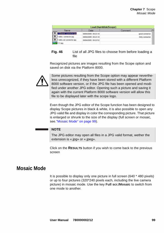
Chapter 7 ScopeMosaic Mode
Recognized pictures are images resulting from the Scope option and saved on disk via the Platform 8000.
Even though the JPG editor of the Scope function has been designed to display Scope pictures in black & white, it is also possible to open any JPG valid file and display in color the corresponding picture. That picture is enlarged or shrunk to the size of the display (full screen or mosaic, see."Mosaic Mode" on page 99).
Click on the RESULTS button if you wish to come back to the previous screen
Mosaic ModeIt is possible to display only one picture in full screen (640 * 480 pixels) or up to four pictures (320*240 pixels each, including the live camera picture) in mosaic mode. Use the key Full scr./Mosaic to switch from one mode to another.
Fig. 46 List of all JPG files to choose from before loading a file
Some pictures resulting from the Scope option may appear neverthe-less unrecognized, if they have been stored with a different Platform 8000 software version, or if the JPG file has been opened and modi-fied under another JPG editor. Opening such a picture and saving it again with the current Platform 8000 software version will allow this file to be displayed later with the scope logo.
NOTE
The JPG editor may open all files in a JPG valid format, wether the extension is «.jpg» or «.jpeg».
User Manual 780000002/12 99

Chapter 7 ScopeMosaic Mode
You may select any of the pictures by using the arrow keys and .
The selected picture is framed in green.
The toolbar on the right varies according to which picture is selected (camera, or static picture).
Camera
All the Contrast and Luminosity settings are available just like in full screen.
Snapshot The live picture from the camera is frozen but does notreplace the live picture at position 1. The new snapshotis placed at the second position, and all existing picturesare pushed to the next position.
Fig. 47 Mosaic mode
Position 1 :LIVE CAMERA
Position 2:Snapshot saved on disk : connector cleaned
Position 3 : Connector before being cleaned
Position 4 : Regular JPEG imageSelected picture
If all positions were taken, the picture that was once at the fourth posi-tion is unloaded from memory. Frozen pictures and snapshots are lost, unless they were saved on disk.
100 User Manual 780000002/12

Chapter 7 ScopeMosaic Mode
Static pictures
Comment It is possible to add a comment to a picture, just like infull screen.
File toolbar The File toolbar is also available in mosaic mode. Actions made by this toolbar will concern the selected file.
Click on the FILE button to access the File toolbar on the right of the screen.
Up to two choices are presented :
Load Refer to "Loading a picture" on page 98
Save This choice is only available if the picture has beenrecognised by the system as a Scope picture, eitherbefore opening it or after opening it (pictures createdwith different versions). When this choice is available,refer to "Saving a picture" on page 98.
A new loaded picture will take the place of the selected picture, unless:
– the selected picture corresponds to the camera (first position). In this case, the rule is the same as when a snapshot is made (see "Camera" on page 100).
– free spots are available in the mosaic. In this case, the new picture takes the second position while other ones are pushed to the next position.
NOTE
Clicking on Save while the camera is selected will both create a snap-shot (see "Camera" on page 100) and save it on disk.
User Manual 780000002/12 101

Chapter 7 ScopeMosaic Mode
102 User Manual 780000002/12

Chapter 8 Desktop applications
8
Several desktop applications are provided to you, thanks to the integra-tion of free software released under the free licences (GPL, LGPL, BSB or other). Their purpose is to bring more functionality to the Platform 8000. JDSU doesn’t provide any warranty or support regarding these free software.To access desktop applications, press the button SYSTEM, and the soft key Desktop applications.
The topics discussed in this chapter are as follows:
– "PDF viewer" on page 104
– "Web browser" on page 105
NOTE
The PDF is a standard application on the Platform 8000.
The navigator is available exclusively if the CompactFlash option is set.
User Manual 780000002/12 103

Chapter 8 Desktop applicationsPDF viewer
PDF viewerGeneral information is provided in this chapter. Please refer to the button
inside the PDF viewer to find the web site where complete docu-mentation may be found.
Opening a PDFdocument
The simplest way to open a pdf file is to press FILE. Select Explorer, look for your file and then select Load >Confirm Load to load the corre-sponding file. The file opens automatically in the PDF viewer.
Interacting witha PDF
document
Once your document is open, you may browse through different pages very quickly, zoom to a particular level, find a special name or sentence, rotate the page... All these features are available via buttons on the screen.
The buttons on the right are pressed using the functions keys of the Plat-form 8000, the touchscreen or via the mouse. The buttons on the bottom of the PDF viewer, may only be used with a mouse or a touchscreen.
A PDF document is always loaded to fit to the screen in width. You may later adapt the zoom level if necessary.
Fig. 48 PDF Viewer Graphical User Interface
Go back 10 pages
Go back 1 page #
Go to next page #
Go to 10 pages further
Rotate the page
Exit PDF viewer
About the Web browser
Go back to previous page
Go back to next page seenFind
Display the current page #
Change zoom level
Open file
104 User Manual 780000002/12

Chapter 8 Desktop applicationsWeb browser
Web browserPlease refer to the Help page in the Help menu from this application (see figure "Web browser application menu" on page 105), to find a complete documentation.
Starting theweb browser
To access this application, click on the soft key Web browser
The web browser is launched. You can see the icon at the top of the screen.
The application menu is hidden until you request it. To access the Web browser application menu, click on the top of the screen. The menu is displayed and you may perform any necessary actions.
Setting theinternet
connection
The connection mode to internet is the same as the one defined for e-mail. Possible choices are modem or ethernet. Make sure you set this setting correctly to be able to access the internet (see “File Export” on page 60).
Make sure to configure your proxy if needed (go to the Web browser Setup menu: network options).
You need to select Setup / Save options in order to save your changes for the next time you launch the web browser.
NOTE
You may scroll in all directions using the direction key pad of the Plat-form 8000 or of an external keyboard, or by dragging the scroll bars with the mouse.
Fig. 49 Web browser application menu
User Manual 780000002/12 105
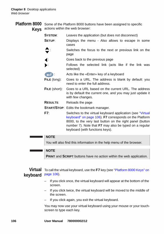
Chapter 8 Desktop applicationsWeb browser
Platform 8000Keys
Some of the Platform 8000 buttons have been assigned to specific actions within the web browser:
SYSTEM: Leaves the application (but does not disconnect)
SETUP: Displays the menu - Also allows to escape in somecases
: Switches the focus to the next or previous link on thepage
: Goes back to the previous page
: Follows the selected link (acts like if the link wasselected)
: Acts like the «Enter» key of a keyboard
FILE (long): Goes to a URL. The address is blank by default: youneed to enter the full address.
FILE (short): Goes to a URL based on the current URL. The addressis by default the current one, and you may just update itwith few changes.
RESULTS: Reloads the page
START/STOP: Edits the bookmark manager.
F7: Switches to the virtual keyboard application (see "Virtualkeyboard" on page 106). F7 corresponds on the Platform8000, to the very last button on the right panel (buttonnumber 7). Note that F7 may also be typed on a regularkeyboard (with functions keys).
Virtualkeyboard
To call the virtual keyboard, use the F7 key (see "Platform 8000 Keys" on page 106).
– If you click once, the virtual keyboard will appear at the bottom of the screen.
– If you click twice, the virtual keyboard will be moved to the middle of the screen.
– If you click again, you exit the virtual keyboard.
You may now use your virtual keyboard using your mouse or your touch-screen to type each key.
NOTE
You will also find this information in the help menu of the browser.
NOTE
PRINT and SCRIPT buttons have no action within the web application.
106 User Manual 780000002/12

Chapter 8 Desktop applicationsWeb browser
Virtual Keyboard application menu
You may change the keyboard according to your country and/or access many other functions, by clicking on the key .
This key lets you access the full application menu. You may also access more information about the virtual keyboard.
To leave the virtual keyboard, click on F7 until it disappears.
Opening a PDFdocument
PDF documents may be opened and read within the Web browser. Please refer to "PDF viewer" on page 104 for more information about that application.
When you try to follow a link to a PDF file, you are requested to choose whether you wish to save the file or to directly open it.
If you want to open the PDF viewer within the Web browser, you must further click on the icon to go back to the web browser.
Leaving theweb browser
Depending on how long you want to leave the web browser and on your connection mode, you may:
– Leave the web browser running and switch to another task. To do this: click on the SYSTEM button. You can see that the Web icon remains, to indicate that the web application is still running in the background. Nevertheless, you have now a complete access to all the Platform 8000 functionality. To go back, you must select again the web browser in the Desktop Applications menu. The applica-tion will reopen much faster, and all your environment will be the same (last current page, possibilities to go back...)
– Quit the application using the Web browser application menu: choose FILE, then press Exit and confirm. You should use this method if you are connected by modem to insure that your connec-tion is no longer working.
NOTE
In case you have neither a mouse nor a touchscreen, you may still move and select keys using the direction keypad of your Platform 8000.
NOTE
The web browser will open a PDF document, not a URL including a PDF file.
User Manual 780000002/12 107

Chapter 8 Desktop applicationsWeb browser
108 User Manual 780000002/12

Chapter 9 File management
9
The files management with the Base Unit can be performed, wether a module is set onto the Base or not.The topics discussed in this chapter are as follows:
– “File menu” on page 110
– “Directory edit function” on page 114
– “File editing function” on page 116
– “CD-Rom burning” on page 121
CAUTION
If no module is set into the Base Unit, or if no module is selected on the System page, the file of Fiber Optic function (i.e. the otdr, pmd, cd...files) can only be opened using the menu Standalone Results > Consult Fiber Optics.
The following chapter discuss about the management of files, other than FO ones, using the FILE button, when no module is set into the Platfomr or when the FO Module is not selected on the System page (see the 8100 Module Series User Manual for the file reading and trace display - ref 8100M02).
User Manual 780000002/12 109

Chapter 9 File managementFile menu
File menu– Press the FILE button.
The File menu appears.
Description ofthe explorer
The explorer is used to select the storage medium, and to create or rename directories and files:
– The left-hand part presents the storage architecture. Use the keys and to move around among all the media and their respective directories.
– The right-hand part displays all the files present in the directory selected.
The direction keys can be used to move horizontally between the two parts and vertically within each zone.
Storage media For saving or recalling data, the Base Unit offers a wide choice of media, both built-in and external.
Free space on selected media is clearly displayed at the bottom of the left panel.
Fig. 50 File Menu
Free space for the media selected
110 User Manual 780000002/12
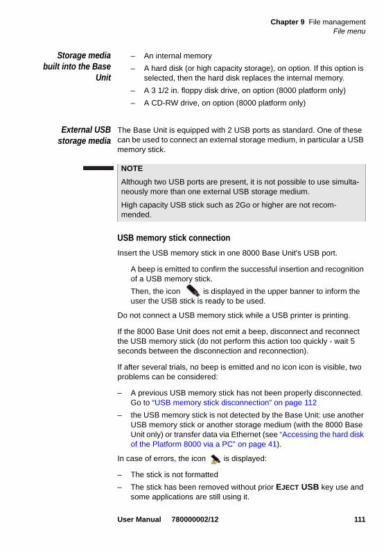
Chapter 9 File managementFile menu
Storage mediabuilt into the Base
Unit
– An internal memory
– A hard disk (or high capacity storage), on option. If this option is selected, then the hard disk replaces the internal memory.
– A 3 1/2 in. floppy disk drive, on option (8000 platform only)
– A CD-RW drive, on option (8000 platform only)
External USBstorage media
The Base Unit is equipped with 2 USB ports as standard. One of these can be used to connect an external storage medium, in particular a USB memory stick.
USB memory stick connection
Insert the USB memory stick in one 8000 Base Unit's USB port.
A beep is emitted to confirm the successful insertion and recognition of a USB memory stick.
Then, the icon is displayed in the upper banner to inform the user the USB stick is ready to be used.
Do not connect a USB memory stick while a USB printer is printing.
If the 8000 Base Unit does not emit a beep, disconnect and reconnect the USB memory stick (do not perform this action too quickly - wait 5 seconds between the disconnection and reconnection).
If after several trials, no beep is emitted and no icon icon is visible, two problems can be considered:
– A previous USB memory stick has not been properly disconnected. Go to “USB memory stick disconnection” on page 112
– the USB memory stick is not detected by the Base Unit: use another USB memory stick or another storage medium (with the 8000 Base Unit only) or transfer data via Ethernet (see “Accessing the hard disk of the Platform 8000 via a PC” on page 41).
In case of errors, the icon is displayed:
– The stick is not formatted
– The stick has been removed without prior EJECT USB key use and some applications are still using it.
NOTE
Although two USB ports are present, it is not possible to use simulta-neously more than one external USB storage medium.
High capacity USB stick such as 2Go or higher are not recom-mended.
User Manual 780000002/12 111

Chapter 9 File managementFile menu
If the size of the free space is not correct, the USB memory stick must be formatted.
a Press the SYSTEM button
b Successively select Expert Tools>Media Utilities>Usbflash Format
c Confirm your choice to format the USB memory stick
d Once formatted, disconnect the USB memory stick using the Eject USB key and reconnect it.
USB memory stick disconnection
Before disconnecting the USB memory stick, always select a storage device different from usbflash (select harddisk for example) in the explorer.
Make sure you no longer have any running applications using the usbflash storage media.
The user must push the EJECT USB key, which is available in File > Explorer or Link Manager, but also in Expert Tools > Media Utilities.
The icon becomes to indicate it can be removed safely. In this state, the USB stick cannot be used anymore
The USB memory stick can then be disconnected from the Base Unit's USB port.
The disconnection of the USB memory stick produces one beep.
As for any media formatting, please note that all data present on the USB memory stick will be irremediably lost.
When a file is moved in the explorer of the Base Unit, the end of the move on the screen does not mean that writing of data into the memory is complete. Some data may still be in a writing process if the storage unit is removed prematurely.
NOTE
If the Base Unit operates on battery and is switched off before the USB memory stick is properly disconnected, all the applications using the usbflash storage media will be automatically turned off and the USB memory stick can be disconnected afterwards without any prob-lem.
112 User Manual 780000002/12

Chapter 9 File managementFile menu
Standard CompactFlash card (8000
platform only)
The Base Unit is equipped as standard with a slot in which a Compact Flash card can be inserted.
Remote Base Unitand data transfer
During a data transfer (with the option Data/Talkset), the distant Base Unit hard drive connected by the fiber is displayed as a storage media. File and directory edition features may all be used in the same manner with this storage media as with the other ones.
Abbreviations forstorage media
The abbreviations used in the explorer for the different storage media are:
NOTE
If the 8000 is on mains and is switched off before the USB memory stick is properly disconnected, the 8000 needs to be completely switched off (using the ON/OFF button and main plug unplugged).
NOTE
The USB memory stick can also be removed from the Base Unit using the Expert Tools > Media Utilities menu (see “Removing the USB memory stick” on page 66).
The Compact Flash card must be inserted before switching on the instrument. It is strongly recommended that this medium should not be withdrawn or reinserted while the instrument is switched on.
Abbreviation Storage medium
harddisk Hard disk
disk Internal flash memory (if no hard disk)
floppy Floppy disk
cdrom CD-ROM
usbflash USB memory stick
cflash Compact Flash memory card
masterdisk Hard drive from the remote Base Unit which initiated the connection
User Manual 780000002/12 113
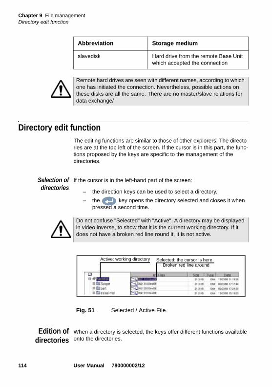
Chapter 9 File managementDirectory edit function
Directory edit functionThe editing functions are similar to those of other explorers. The directo-ries are at the top left of the screen. If the cursor is in this part, the func-tions proposed by the keys are specific to the management of the directories.
Selection ofdirectories
If the cursor is in the left-hand part of the screen:
– the direction keys can be used to select a directory.
– the key opens the directory selected and closes it when pressed a second time.
Edition ofdirectories
When a directory is selected, the keys offer different functions available onto the directories.
slavedisk Hard drive from the remote Base Unit which accepted the connection
Abbreviation Storage medium
Remote hard drives are seen with different names, according to which one has initiated the connection. Nevertheless, possible actions on these disks are all the same. There are no master/slave relations for data exchange/
Do not confuse "Selected" with "Active". A directory may be displayed in video inverse, to show that it is the current working directory. If it does not have a broken red line round it, it is not active.
Fig. 51 Selected / Active File
Active: working directory Selected: the cursor is hereBroken red line around
114 User Manual 780000002/12

Chapter 9 File managementDirectory edit function
Create Directory This key allos the creation of a new directory.
– Select the storage media on which the directory will be stored the new directory
– Click on Create Directory
The editor enables entry of its name.
– Enter a name for the directory
– Click on Validate
The directory is saved in the storage media previously selected.
Rename Directory This function allows to rename the directory selected.
– Select the directory which name must be modified.
– Click on Rename Directory
The editor is displayed
– Enter a new nam for the directory
– Click on Validate
The directory is saved under a new name, on the same storage media.
Edit This key opens a new menu providing functions for editing the directo-ries.
Fig. 52 Operations available on the directories
Operations on the
directories
User Manual 780000002/12 115

Chapter 9 File managementFile editing function
Copying a directory on the same media or on another media
– Select the directory to be copied
– Click on Copy or Cut
– Select the directory and / or the storage media in which the directory will be placed.
– Click on Paste
Remove adirectory
The Edit menu allows to delete a directory from the storage media.
– Select the directory to be deleted.
– Click on Delete
A confirmation message is displayed: click on Yes to confirm the directory removal or on No to cancel the operation.
File editing functionOnce the file(s) is / are selected, several operations are available with the Base Unit.
The right-hand part of the screen can be used to work on the files in the directory selected.
NOTE
A whole directory with its contents can be copied into another direc-tory or on to another storage medium.
Fig. 53 Available operations on files
Operations onfiles
116 User Manual 780000002/12

Chapter 9 File managementFile editing function
File Format andType
A table gives the list of the files in the directory, showing for each one: its name, size, type and date of creation.
File Types For files recognized by the Base Unit, the types are symbolized by icons.
OSA file (.OSA extension)
OTDR file (.SOR extension)
Multi OTDR file (.MSOR extension)
OEO file (.OEO extension)
PMD file (.PMD extension)
CD file (.CD extension)
AP file (.AP extension)
LTS file (.LTS extension)
ORL file (.ORL extension)
CD ODM file (.OCD extension)
Format of files OTDR files that can be read by the Base Unit are type Bellcore 1.0, 1.1 and 2.0.
Other files that can be read by the Base Unit are specific to this instru-ment.
To read other formats, use JDSU’s FiberTrace or FiberCable software.
Easy fileselection
To select one or several files:
– Click on to pass from the directory to hte file selection
– Use the arrows and to move around the files list.
– Click on to validate the selection of each file wished.
To select all the files from the directory, click on Select All.
User Manual 780000002/12 117

Chapter 9 File managementFile editing function
To select a list of files using the keys of the Platform:
1 Select and validate the first file of the list (red display)
2 Set the cursor on the last file of the list (blue display)
3 click on the right arrow key to select all the files from the list.
Rename File Opens the editor to modify the name of the file:
– Select the file in the list
– Click on Edit > Rename File.
The Editor is displayed.
– Enter a new name for the file.
– Click on Enter
Sorting the files Wether files are selected or not, the key Sort allows to access to a sub-menu allowing to sort te file accorfing to pre-defined parameters:
Fig. 54 Selection Directory - File
Directory selected File selected
NOTE
If a mouse is used, click on a file to select it, and click again to dese-lect it.
Fig. 55 List of files selected
If no file has been selected by the key, the file where the cursor is positioned is taken as selected.
On the other hand, if a file has been selected with the key, and the cursor is on another file, the latter is not selected!
118 User Manual 780000002/12

Chapter 9 File managementFile editing function
– Sort by name: the files will be displayed in an ascending order (from A to Z). If you clicj once again on the key, the files will be displayed in a descending order (from Z to A).
– Sort by Size: by cliking once on this key, the files will be displayed from the smallest to the heaviest one. Clicking a second time allows to display the files in opposite order.
– Sort by Type: clicking once on this key; the MTS will display the files in an ascending order (the file type A to file type W). By clicking again, the Base Unit will display the files in opposite order.
– Sort by Date: clicking once on this key; the MTS will display the files from the more recent to the less one. By clicking again on this key, the Base Unit will display the files from the older to the more recent one.
Copying one /several file(s)
You can copy files from one storage media or from a directory to another.
– Select the file(s) to be copied
– Click on Edit > Copy or Cut
– Select the directory / the storage media in which the file(s) will be saved.
– Click on Paste
Merging txtFiles
When saving a measurement result, in addition to the trace file, a txt file can be saved for each measurement type:
– with OTDR, OEO, PMD, OSA and AP traces, select «+ txt» in the line File Type / Save mode on Menu screen (see 8100 Module Series User Manuals).
– with the LTS and ORL functions, the txt file is automatically gene-rated when saving the results.
The key Merge is used to merge several txt files from measurements into one txt file, putting together the results of all txt files.
– In the explorer, select the txt files generated with the tracefilesyou want.
– Click on Edit > Merge key
The file merged_files.txt is automatically saved in the same directory as the one where the txt files have been selected.
HINWEIS
The file merged_files.txt can be renamed once it is saved.
User Manual 780000002/12 119

Chapter 9 File managementFile editing function
Send by mail This option appears if Mail has been defined with Ethernet, in the system setup menu (see “File Export” on page 60).
1 Select the file(s) to be sent.
2 Click on Send by mail
The editor is displayed.
3 You will have to fill in the two following fields:
– Mail To: Using the key , display the edition window which allows you to enter the name of the recipient.
– Subject: in the same way, enter the subject of the mail or a comment if necessary. By default, the name of the mail is «Result + sending date».
4 Click on Validate
Once the mail has been sent, the following message is displayed: Mail Sent. Click on any key to follow.
Fig. 56 Enter e-mail address
Enter an e-mail address
NOTE
If at least one function is selected in the System page (yellow icon), this two parameters «Mail to» and «Subject» can be configured by default in the Explorer page > File Export (see 8000 Module Manual)
120 User Manual 780000002/12

Chapter 9 File managementCD-Rom burning
CD-Rom burning1 Go to the file explorer
2 Select the directory and/or the files to burn on the CD
3 Click on Edit
4 Click on Copy or Cut
5 Click on CD-R tools
6 If the CD-Rom is a CD-RW with data to be erased first, click on Erase CD-RW, otherwise go to step 8
7 A dialog box request to confirm that you want to erase existing data. Click Yes to continue
A new message is displayed to inform you that all data is being erased on the CD-RW.
8 Click on Burn CD or Burn and Close CD, according to whether you wish to close the session of your CD or not.
A new dialog box is displayed, asking you to check that the CD-Rom door is securely closed.
If you cut the file(s) to save it to on the CD, they will not be on the Base Unit anymore.
Fig. 57 CD-R tools
User Manual 780000002/12 121

Chapter 9 File managementCD-Rom burning
A message is displayed to indicate that you need to wait, the CD-Rom is being burnt.
9 A last message appears a few minutes later to let you know that the CD-Rom has now been successfully burnt Click on any key to remove the message.
10 You may now securely remove the CD-Rom.
122 User Manual 780000002/12

Chapter 10 Maintenance
10
This chapter gives the main maintenance procedure for the Platform 8000.The topics discussed in this chapter are as follows:
– “Maintenance procedure” on page 124
– “Cleaning” on page 125
– “Precautions relating to optical connections” on page 125
– “Installing a new version of the software” on page 126
– “Replacement of the small PCB battery (for backup)” on page 136
– “General information on warranty” on page 137
– “Touchscreen calibration” on page 138
For software updates, or to find our JDSU representatives and technical support offices around the world, please visit our web site: www.jdsu.com.
User Manual 780000002/12 123

Chapter 10 MaintenanceMaintenance procedure
Maintenance procedure
Maintenance work on this instrument must only be undertaken by qualified personnel using suitable equipment.
In most cases, it is advisable to contact the nearest JDSU Service Centre, which will undertake the appropriate troubleshooting and repair work.
The performance and technical complexity of the Platform 8000 class this instrument in a new generation of equipment, for which JDSU has laid down a maintenance policy based on the principle of standard module replacement.
In implementation of this policy, we have set up powerful card trouble-shooting test resources in our factories and a rapid dispatch system operating between our factories and branches.
Only by this procedure can the high quality of the instrument continue to be ensured after repair work. This procedure also has the advantage of reducing repair costs and time.
In the interests of quality and efficiency, we strongly recommend adop-tion of the following procedure in the event of a fault, before any other steps are taken:
– Verify that the instrument is plugged in.
– Check the connections of any peripheral equipment to the Platform 8000.
– If a fault is detected, or in case of doubt, it is advisable to contact the nearest JDSU Service Centre, which will undertake the appropriate repair work.
Returning aninstrument
When returning an instrument, it is essential to indicate the following minimum information:
– the type and serial number of the instrument (on the identification label) and the configuration code (under the bar code)
– a description of the fault found on the instrument.
The returned instrument will then be repaired and calibrated.
124 User Manual 780000002/12

Chapter 10 MaintenanceCleaning
Guaranteeconditions
Any repair operation supervening within the guarantee period of the instrument will be carried out at the expense of JDSU. However, for any sub-assembly upon which work has been carried out otherwise than by JDSU Service Centers, the cost of a replacement sub-assembly will be invoiced.
Cleaning
Cleaning platesand housings
The front and rear plates and the housings may become tarnished with handling. To clean them, use only a rag moistened with soapy water.
Never use any product containing acetone, trichloro-ethylene, benzine or alcohol, as these will attack the printed markings.
Cleaning thescreen
To clean the screen, use an antistatic product.
Precautions relating to optical connections– The normal operating life of an optical connector is usually of the
order of a few hundred manipulations. It is therefore advisable to manipulate the optical connections of the Platform 8000 as rarely as possible.
– The proper operation of the instrument and its accuracy of measure-ment are dependent on the cleanliness of the environment and the optical connectors as well as the care taken in its manipulation.
– The optical connectors must therefore be clean and dust-free. If the optical connection is not being used, protect the connections of Plat-form 8000 using the protective plugs provided.
As an example, the results of measurements made with connectors that have not been cleaned will display an error of the order of 10% for all measurements. This error is additional to other errors inherent in the measurement process and due, for example, to the quality of the fiber (circularity and concentricity), the means of connection (axis alignment, distance between fiber faces, quality of fiber faces) and propagation modes.
User Manual 780000002/12 125

Chapter 10 MaintenanceInstalling a new version of the software
Cleaning theoptical cable
connector
– Use a non-linting type of paper, such as Joseph paper, soaked in isopropylic alcohol.
– Pay particular attention to the polished face of the fiber, rubbing it in a direction perpendicular to the axis of the fiber.
Cleaning theoptical
connections ofthe Platform
8000
– Squirt a highly volatile solvent (such as isopropylic alcohol) into the connector.
– Blow out the connector using a clean dry air supply from an aerosol can fitted with an extension.
Installing a new version of the software
Where and howto obtain the
new software
The new version of the software can either be procured on a storage medium (CD-ROM, USB memory stick or CompactFlash memory card) from your JDSU Customer Service, or can be downloaded from JDSU’s internet site: www.jdsu.com.
NOTE
If your module has a universal connector, unscrew its adaptor to access the ferule.
When a new software version is loaded, there is a risk of re-initializa-tion of the internal memory. Before installing the new software, it is therefore advisable to to save the results in the memory, using the Save function in the Memory menu called up by the FILE button.
Do not interrupt the installation process, as this could damage the instrument.
To avoid any interruption of the installation procedure, the Platform 8000 must be operating on the mains: if the procedure is started while operating on battery, a message indicates that the instrument must be connected to the mains.
Be sure you have configured the Security mode of the equipment to Standard, and not to Enhance in the System Page > I/O Interfaces > Ethernet > Security.
126 User Manual 780000002/12

Chapter 10 MaintenanceInstalling a new version of the software
Downloadingfrom Internet
When the software is obtained from the Internet, it must be saved on a storage medium before the software upgrade of the product can be carried out. To do this, on the JDSU web site:
1 Open the page of the product concerned: MTS 8000 Scalable Optical Test Platform or T-BERD 8000 Scalable Optical Test Plat-form
2 Click on the tab Downloads.
3 Click on the link 8000 Firmware Update
A new page opens explaining the process
4 Follow the instructions to download the exe file and update the Platform 8000.
Installationfrom a PC
The new versions can be installed according 2 methods:
– from the harddisk of a PC
– from the CD-ROM drive of a PC
Installation fromthe harddisk of a
PC
1 Connect the Platform 8000 into mains with the AC plug, and switch it on.
2 Connect the Platform 8000 to the PC by an Ethernet link
3 On the PC, download and save the .exe upgrade get from the web (www.jdsu.com).
4 Once the transfer is completed, and in order to perform the upgrade, the «.exe» file shall be extracted under a root of the PC. The files extracted shall be placed under C:\ or under a drive created with the following process:
a Put the release under a directory, such as C:\8000_Base_Upgrade:\
NOTE
Once the upgrade has been loaded from Internet, the new version cannot be burned with the CD ROM of the MTS / T-BERD Platform 8000. Burn the CD-ROM of the PC, using CD burner softwares rec-ommended by JDSU.
NOTE
Use a cross over if the Platform 8000 is directly connected to the PC or a direct cable if the Platform 8000 is connected to the LAN.
User Manual 780000002/12 127

Chapter 10 MaintenanceInstalling a new version of the software
b Open a DOS console, by selecting Windows > Start (bottom right of the PC screen) > All programs > Accessories > Command prompt.
c Then type the command subst N: C:\upgrade\
d Close the DOS console.
This command will create a virtual drive N: (N: is an example)1
5 Go to the driver, using Windows Explorer
6 Double click on the .exe file: A window called "Winzip self extractor", will appear. Check that the folder is correct i.e. the C:\ drive or the newly created N:\ drive is appearing "Name:\" then press “Unzip”. If not, click on ”Browse” in order to select the right drive.
A message indicating the number of files that have been unzipped successfully will then appear.
7 Press "Close".
8 Run TFTPD32.exe: note the «Server Interfaces» address which appears in the TFTPD32 window.
9 Run FTP server.exe. An error message will appear: click on OK.
The window «Pablo’s FTP server» is displayed. Click on the green arrow (or select menu File > Start).
10 On the Platform 8000, press the SYSTEM key, then System Setup: in Utility > Upgrade Parameters > Server address, enter the IP address previously noted (see "6" above).
11 Quit the System menu and then press, in succession, Expert Tools > Software Upgrade > Upgrade via Ethernet.
The message «Verify IP address of PC server» appears.
12 Click on Confirm.
1."N:" may be replaced by another letter if necessary and "8000_Base_Upgrade"corresponds to the directory where the updrade files have been unzipped.
Fig. 58 WinZip Self Extractor
128 User Manual 780000002/12

Chapter 10 MaintenanceInstalling a new version of the software
The list of the software versions available on the PC is displayed next to the versions installed on the Platform 8000.
More recent version on the PC than on the Platform 8000
Less recent version on the PC than on the Platform 8000
Identical version on the PC and on the Platform 8000
13 Click on Show Previous choice or Show Next Choice to display the previous and next versions available.
14 Click on Confirm this Choice to start the upgrade of the selected software(s).orClick on Confirm All Choices to upgrade all versions.
Upgrading begins. The Platform 8000 is automatically rebooted. Upgrading takes several minutes. At the end, the Platform 8000 is automatically restarted (if the boot version is superior to version 01.16).
15 On the PC, close the two windows opened to perform the installa-tion.
16 Once the upgrade is completed, you may remove the virtual drive (in our example "N:") by using the command subst N: /d.
The key Confirm All Choices appears exclusively if multiple release is available, and once all the releases available have been displayed using key Show Next Choice.
NOTE
The software versions list does not always appear (cf previous ver-sions) as well as the Show Previous / Next Choice buttons and the Confirm/Continue key. In this case, the upgrading starts automati-cally.
User Manual 780000002/12 129

Chapter 10 MaintenanceInstalling a new version of the software
Installation fromthe CD-ROM drive
of a PC
1 Connect the Platform 8000 into mains with the AC plug, and switch it on.
2 Connect the Platform 8000 to the PC by an Ethernet link
3 Insert the CD-ROM in the drive of the PC.
4 On the PC, use Windows Explorer to open the CD-ROM.
5 Run TFTPD32.exe: note the «Server Interfaces» address which appears in the TFTPD32 window.
6 Run FTP server.exe. An error message will appear: click on OK.
The window «Pablo’s FTP server» is displayed. Click on the green arrow (or select menu File > Start).
7 On the Platform 8000, press the SYSTEM key, then System Setup: in Utility > Upgrade Parameters > Server adress, enter the IP address previously noted (see "5" above).
8 Quit the SYSTEM menu and then press, in succession, Expert Tools > Software Upgrade > Upgrade via Ethernet.
The message Verify IP address of PC server appears.
9 Click on Continue.
The list of the software versions available on the PC is displayed next to the versions installed on the Platform 8000.
10 Click on Show Previous choice or Show Next Choice to display the previous and next versions available.
11 Click on Confirm to start the upgrade of the selected software(s).orClick on Confirm All Choices to upgrade all versions.
NOTE
Use a cross over if the Platform 8000 is directly connected to the PC or a direct cable if the Platform 8000 is connected to the LAN.
The key Confirm All Choices appears exclusively if multiple release is available, and once all the releases available have been displayed using key Show Next Choice.
130 User Manual 780000002/12

Chapter 10 MaintenanceInstalling a new version of the software
Upgrading begins. The Platform 8000 is automatically rebooted. Upgrading takes several minutes. At the end, the Platform 8000 is automatically restarted (if the boot version is superior to version 01.16).
12 On the PC, close the two windows opened to perform the installa-tion.
Installationfrom Ethernet
Before starting the software upgrade via Ethernet, make sure the IP adress of the PC server.
1 Press, in succession, Expert Tools > Software Upgrade > Upgrade via Ethernet.
The message Verify IP address of PC server appears.
2 Click on Continue.
The list of the software versions available on the PC is displayed next to the versions installed on the Platform 8000.
3 Click on Show Previous choice or Show Next Choice to display the previous and next versions available.
4 Click on Confirm to start the upgrade of the selected software(s).orClick on Confirm All Choices to upgrade all versions.
NOTE
The software versions list does not always appear (cf previous ver-sions) as well as the Show Previous / Next Choice buttons and the Confirm/Continue key. In this case, the upgrading starts automati-cally.
The key Confirm All Choices appears exclusively if multiple release is available, and once all the releases available have been displayed using key Show Next Choice.
NOTE
The software versions list does not always appear (cf previous ver-sions) as well as the Show Previous / Next Choice buttons and the Confirm/Continue key. In this case, the upgrading starts automati-cally.
User Manual 780000002/12 131

Chapter 10 MaintenanceInstalling a new version of the software
Upgrading begins. The Platform 8000 is automatically rebooted. Upgrading takes several minutes. At the end, the Platform 8000 is automatically restarted (if the boot version is superior to version 01.16).
Installationfrom a CD-ROM
Updating from a CD-ROM can be done directly, if the Platform 8000 is equipped with a CD-ROM drive.
1 Connect the Platform 8000 into mains with the AC plug, and switch it on.
2 Insert the CD-ROM in the drive of the Platform 8000.
3 Press the SYSTEM key and then, in succession, the keys Expert Tools > Software Upgrade > Copy from CD.
The message Insert the CD in the drive is displayed
4 Click on Confirm.
The list of the software versions available on the PC is displayed next to the versions installed on the Platform 8000.
5 Click on Show Previous choice or Show Next Choice to display the previous and next versions available.
6 Click on Confirm to start the upgrade of the selected software(s).orClick on Confirm All Choices to upgrade all versions.
Upgrading starts. The Platform 8000 is automatically rebooted. The installation process takes several minutes. At the end, the Platform 8000 is automatically restarted (if the boot version is superior to version 01.16).
The key Confirm All Choices appears exclusively if multiple release is available, and once all the releases available have been displayed using key Show Next Choice.
NOTE
The software versions list does not always appear (cf previous ver-sions) as well as the Previous / Next Choice buttons and the Con-firm/Continue key. In this case, the upgrading starts automatically.
132 User Manual 780000002/12

Chapter 10 MaintenanceInstalling a new version of the software
Installationfrom a
CompactFlashmemory card
You must be equipped with a CompactFlash memory card with a minimum capacity of 128 Mo.
1 Switch off and unplug your Platform 8000.
2 Insert the CompactFlash memory card in which the new unzipped software has been loaded, into the slot on the Platform 8000 provided for this purpose.
3 Connect the Platform 8000 into mains with the AC plug and switch it on.
4 Press the SYSTEM button, then successively Expert tools > Soft-ware Upgrade > Copy from CF.
5 Click on Confirm.
The list of the software versions available on the PC is displayed next to the versions installed on the Platform 8000.
6 Click on Show Previous choice or Show Next Choice to display the previous and next versions available.
7 Click on Confirm to start the upgrade of the selected software(s).orClick on Confirm All Choices to upgrade all versions.
Upgrading begins. The Platform 8000 is automatically rebooted. Upgrading takes several minutes. At the end, the Platform 8000 is automatically restarted (if the boot version is superior to version 01.16).
The Software Upgrade from a Compact Flash memory card is not possible if the instrument is delivered with the Application Card reference E80CFAPP.
The key Confirm All Choices appears exclusively if multiple release is available, and once all the releases available have been displayed using key Show Next Choice.
NOTE
The software versions list does not always appear (cf previous ver-sions) as well as the Show Previous / Show Next Choice buttons and the Confirm/Continue key. In this case, the upgrading starts automatically.
User Manual 780000002/12 133

Chapter 10 MaintenanceInstalling a new version of the software
Installationfrom a USB
memory stick
You must be equipped with a USB memory stick with a minimum capacity of 128 Mo.
Before installing the upgrade, you must format the USB memory stick (steps 1 to 5).
1 Insert the memory stick into one of the sockets on the Platform 8000 provided for this purpose.
The icon is displayed in the upper banner to inform the user the USB stick can be used safely.
2 Switch on the Platform 8000
3 Press the SYSTEM button
4 Successively select Expert tools > Media utilities > Usbflash Format.
5 Confirm your choice to actually format the USB memory stick.
6 Once formated, disconnect the USB memory stick using the Eject USB key
The icon becomes to indicate it can be removed safely. In this state, the USB stick cannot be used anymore
7 Connect the USB memory stick to the PC
USB memory sticks can be very different.
They differ on Hw and Sw aspects, even inside a given brand.
In particular, USB memory sticks targeting audio recording are often formatted in very specific ways and the format is often very different from a standard FAT.
For all these reasons, we advise users to use memory sticks provided by JDSU.
In any case, USB memory sticks which are recognized by the MTS (a beep is generated when plugged on the MTS) but which cannot be read or written, should be formatted on the MTS with the Usbflash Format utility, in Expert tools > Media utilities.
If a problem occurs with the USB stick you are using, contact your Local Technical Assistance Center.
As for any media formatting, please note that all data present on the USB memory stick will be irremediably lost.
134 User Manual 780000002/12
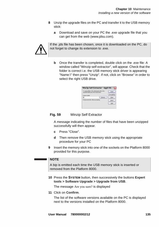
Chapter 10 MaintenanceInstalling a new version of the software
8 Unzip the upgrade files on the PC and transfer it to the USB memory stick:
a Download and save on your PC the .exe upgrade file that you can get from the web (www.jdsu.com).
b Once the transfer is completed, double click on the .exe file: A window called "Winzip self extractor", will appear. Check that the folder is correct i.e. the USB memory stick driver is appearing "Name:\" then press "Unzip". If not, click on "Browse" in order to select the right USB drive.
A message indicating the number of files that have been unzipped successfully will then appear.
c Press "Close".
d Then remove the USB memory stick using the appropriate procedure for your PC
9 Insert the memory stick into one of the sockets on the Platform 8000 provided for this purpose.
10 Press the SYSTEM button, then successively the buttons Expert tools > Software Upgrade > Upgrade from USB.
The message Are you sure? is displayed
11 Click on Confirm.
The list of the software versions available on the PC is displayed next to the versions installed on the Platform 8000.
If the .jds file has been chosen, once it is downloaded on the PC, do not forget to change its extension to .exe.
Fig. 59 Winzip Self Extractor
NOTE
A bip is emitted each time the USB memory stick is inserted or removed from the Platform 8000.
User Manual 780000002/12 135

Chapter 10 MaintenanceReplacement of the small PCB battery (for backup)
12 Click on Previous choice or Next Choice to display the previous and next versions available.
13 Click on Confirm to start the upgrade of the selected software(s). orClick on Confirm All Choices to upgrade all versions
14 Remove the USB stick as prompted
15 The 8000 shuts down
16 Reinsert the USB as required, in the same USB port as previously (repetitive bips advise you to insert the stick).
Upgrading begins. The Platform 8000 is automatically rebooted. Upgrading takes several minutes. During this stage, do not remove the USB stick. At the end, the Platform 8000 is automatically restarted (if the boot version is superior to version 01.16).
Replacement of the small PCB battery (for backup)The Platform 8000 Lithium battery on the microprocessor board ensures that date, time and certain information data are not lost when the instru-ment is switched off.
Checking thebattery
If there is doubt as to whether the battery needs to be changed or not, switch off the instrument. On switching the instrument on again, check whether the date is still correct. If the date has been lost, the battery needs replacing.
Contact your nearest JDSU Customer Service Centre.
This battery has an average life of more than five years.
The key Confirm All Choices appears exclusively if multiple release is available, and once all the releases available have been displayed using key Show Next Choice.
NOTE
The software versions list does not always appear (cf previous ver-sions) as well as the Previous / Next Choice buttons and the Con-firm/Continue key. In this case, the upgrading starts automatically.
136 User Manual 780000002/12
Chapter 10 MaintenanceGeneral information on warranty
Battery replacement should not be carried out by the user:this may be dangerous to the microprocessor board(certain components may be damaged or destroyed)
and requires special tools
General information on warrantyThe warranties described herein shall apply to all commercially available JDSU products. Any additional or different warranties shall apply only if agreed to by JDSU in writing. These warranties are not transferable without the express written consent of JDSU.
HardwareWarranty
JDSU warrants that Hardware Product sold to customer shall, under normal use and service, be free from defects in materials and workman-ship. Information regarding the specific warranty period for this product can be obtained by contacting your local JDSU Customer Service Repre-sentative, or at our web site www.jdsu.com.
JDSU ’s obligation and customer’s sole remedy under this Hardware Warranty is limited to the repair or replacement, at JDSU’s option, of the defective product. JDSU shall have no obligation to remedy any such defect if it can be shown: (a) that the Product was altered, repaired, or reworked by any party other than JDSU without JDSU’s written consent; (b) that such defects were the result of customer’s improper storage, mishandling, abuse, or misuse of Product; (c) that such defects were the result of customer’s use of Product in conjunction with equipment elec-tronically or mechanically incompatible or of an inferior quality; or (d) that the defect was the result of damage by fire, explosion, power failure, or any act of nature.
JDSU performed repairs shall be warranted from defective material and workmanship for a period of ninety (90) days, or until the end of the Initial Warranty Period, whichever is longer. Risk of loss or damage to Product returned to JDSU for repair or replacement shall be borne by customer until delivery to JDSU.
Upon delivery of such product, JDSU shall assume the risk of loss or damage until that time that the product being repaired or replaced is returned and delivered to customer. Customer shall pay all transportation costs for equipment or software shipped to JDSU for repair or replace-ment. JDSU shall pay all transportation costs associated with returning repaired or replaced product to customer.
User Manual 780000002/12 137

Chapter 10 MaintenanceTouchscreen calibration
WARRANTY DISCLAIMER — FOR HARDWARE AND/OR SERVICES FURNISHED BY JDSU, THE FOREGOING WARRANTIES ARE IN LIEU OF ALL OTHER WARRANTEES AND CONDITIONS, EXPRESS OR IMPLIED. JDSU SPECIFICALLY DISCLAIMS ALL OTHER WARRANTIES, EITHER EXPRESS OR IMPLIED, ON ANY HARD-WARE, DOCUMENTATION OR SERVICES INCLUDING BUT NOT LIMITED TO WARRANTIES RELATING TO QUALITY, PERFOR-MANCE, NONINFRINGEMENT, MERCHANTABILITY OR FITNESS FOR A PARTICULAR PURPOSE, AS WELL AS THOSE ARISING FROM ANY COURSE OF DEALING, USAGE OR TRADE PRACTICE. UNDER NO CIRCUMSTANCES WILL JDSU BE LIABLE FOR ANY INDIRECT OR CONSEQUENTIAL DAMAGES RELATED TO BREACH OF THIS WARRANTY.
Touchscreen calibrationIf the Platform 8000 is equipped with a touchscreen, the button Touch-screen Calibration appears in the right hand corner of the setup screen.
To calibrate the touchscreen
1 Push the SYSTEM button
2 Press the System Setup key
3 Press the Touchscreen Calibration key
A grey slightly smaller screen appears, displaying a little target on the left hand corner.
4 Click on this target (preferably with the touchscreen pen).
5 A new target appears then and again for a total of 4 times, in order to click on all corners of the screen.
If all the targets are not correctly touched, the touchscreen cannot be used.
Otherwise, the touchscreen may be used directly.
138 User Manual 780000002/12
Chapter 11 Technical specifications
11
This chapter contains the technical specifications of the Platform 8000 mainframe.The topics discussed in this chapter are as follows:
– “Display” on page 140
– “Memory” on page 140
– “Input/Output” on page 140
– “Power supply” on page 141
– “Dimensions - Weight” on page 142
– “Environment” on page 142
– “Characteristics of the options” on page 144
User Manual 780000002/12 139

Chapter 11 Technical specificationsDisplay
Display
Screen – Back-lit color screen
– Size: 10.4 inch
– Resolution: 800 x 600 pixels
– Standard: standard screen for indoor use, non-tactile.
– Options:
• High visibility screen for indoor and outdoor use
• High visibility touchscreen
Memory– Standard memory: internal Flash memory, minimum capacity 128
Mb (of which a minimum of about 8 Mb are available for data storage)
– Options:
- Hard disk, minimum capacity 10 Gb
- Floppy disk drive(3 1/2")
- CD-ROM drive/re-writer
Input/Output– one VGA port (DB 15 female)
– two USB 1.1 Master ports, for printer, mouse, keyboard, memory key, camera, optical microscope, etc.
– one RJ 45 connector for Ethernet interface 10/100 Mbit/s
– one DIN connector for access to remote functions (future options)
– one RS 232 connector,DB9 male (not used)
– one RJ 11 port for the modem option
– built-in microphone and loudspeaker
– one port for memory, Compact Flash type I
140 User Manual 780000002/12

Chapter 11 Technical specificationsPower supply
Power supply
Battery The instrument can be supplied with one or two Lithium Ion batteries.
Endurance of the Platform 8000 with one battery
Measurement conditions:
- at +25 °C,
- at nominal capacity (6 Ah),
- Platform 8000 equipped with an OTDR plug-in, type SR
Endurance
– Test carried out in accordance with Telcordia GR-196-CORE recom-mendations: lighter backlight for the screen, (3 acquisitions of 30s per 15 minutes and auto-off): up to 11 hours
– With continuous acquisition:- up to 5 hours with normal screen lighting.- up to 4 hours with strong screen lighting.
Mains adapters
Standard Mains Adapter
High power Mains Adapter
Input100-240 V, 50-60 Hz
100-240 V, 50-60 Hz
Output19 V continuous,
3,16 A max24 V continuous, 6,25 A max
ComplianceEN 60950 EN 60950
User Manual 780000002/12 141

Chapter 11 Technical specificationsDimensions - Weight
Dimensions - Weight
Environment
Temperature – Operation on mains supply, excluding options:-20°C to +50°C.
– Operation including all options (guaranteed specifications): 0° to +40° C
– Storage: -20C to +60C
Humidity – 5 to 95% without condensation
Weight
User interface module without options 2.4 kg 5.29 lbs
Receptacle without measurement plug-in 1.16 kg 2.56 lbs
Measurement plug-in ~ 500 g 1.1 lbs
Backplate 485 g 1.07 lbs
Battery pack 1.35 kg 2.97 lbs
Dimensions (mm)Including rubber buffers
Dimensions (mm)Without rubber buffers
User interface module 326 x 267 x 60
inches: 12,8 x 10,5 x 2,3
311 x 259 x 53
inches: 12,2 x 10,2 x 2,1
Backplate 317 x 269 x 20
inches: 12,4 x 10,6 x 0,78
303 x 248 x17
inches: 11,9 x 9,8 x 0,7
Battery pack 317 x 267 x 33
inches: 12,4 x 10,5 x 1,3
306 x 251 x 26
inches: 12 x 9,9 x 1
Receptacle for 2 plug-ins 320 x 253 x 39
inches: 12,6 x 10 x 1,5
320 x 253 x 39
inches: 12,6 x 10 x 1,5
142 User Manual 780000002/12

Chapter 11 Technical specificationsEnvironment
EMI/ESD – CE class A Compliant
– FCC 47-1 Part 15 Compliant
Drop test In accordance with the Telcordia GR-196-CORE recommendations, the Platform 8000 resists the following test:
– 6 impacts dropped from a height of 76 cm (1 impact on each of its 6 sides, with power off).
Shocks The Platform 8000 resists the following test:
– 3 shocks per axis along each of the 3 axes, with power off.
– Impacts of 15g, 1/2 sine, duration 11 ms, at 10 second intervals.
Bumps The Platform 8000 resists the following test:
– 1,000 jolts per axis along each of the 3 axes, with power off.
– Jolts of 15g, 1/2 sine, duration 6 ms, at 1 second intervals.
Vibration The Platform 8000 resists the following vibration tests:
– Complete test comprising 6 cycles along each of the x, y and z axes.
– One cycle of 5 to 200 Hz and back to 5 Hz with a sweep duration of one minute/octave.
– 3 mm amplitude displacement test, for the range 5 Hz to 15 Hz.
– 3g acceleration test for the range 16 Hz to 200 Hz.
Flammability The housing of the Platform 8000 (in ABS, type V0) does not propagate fire.
This is a class A product. In a domestic environnment, this product may cause radio interference in which case the user may be required to take adequate measures.
User Manual 780000002/12 143

Chapter 11 Technical specificationsCharacteristics of the options
Characteristics of the options
Power meter ofthe LTS option
Specifications given for 25°C, after 20 minutes stabilization time and after zero setting.
– Wavelength range: 800 to 1650 nm in steps of 1 nm
– Calibrated wavelengths: 850 / 1310 / 1550 nm
– Accuracy at calibrated wavelengths: ± 0.2 dB (at -30 dBm)
– Input power range : +10 dBm to -60 dBm
– Maximum resolution: 0.01 dB / 0.01n W
– Measurement range:+5 to -50 dBm (-45 dBm from 800 to 1250 nm)
– Linearity within the measurement range: ± 0.2 dB
Talkset – Dynamic range: typically 45 dB at 25°C.
– Jack socket for headset
– Laser, typical wavelength 1550 nm, class 1 (EN60825 and FDA21 CFR Part 1040.10)
Laser sourcesof the LTS
option
Laser
Class 1
– Wavelength laser at 25°C:
1310 ± 30 nm
1550 ± 30 nm
1625 ± 10 nm
– Spectral bandwidth: 5 nm RMS maximum
Output level
– -3.5 dBm
– modulated mean level -6.5 dBm
– Stability1:
± 0.02 dB, short term (15 minutes) for temperature differences of ± 0.3° K
± 0.2 dB, long term (8 hours) for temperature differences of ± 3° K
1.The specifications concerning accuracy and stability do not become valid until 20minutes after switching on, and are only valid with a proper fiber connection.
144 User Manual 780000002/12

Chapter 11 Technical specificationsCharacteristics of the options
Emission mode
– Continuous signal (CW)
– Signal including lambda information for the power meter (Auto-).
– Modulated signal to identify the fiber (at 270, 330, 1k or 2kHz).
– Wavelengths activated one after the other (TwinTest mode).
Manual ORL – Selectable wavelength: 1310 / 1550 nm
– Display range: 0 dB to 60 dB
– Measurement range:5 dB to 45 dB
– Measurement uncertainty (typical value): +/- 1 dB ( 5 dB to 40 dB)
– Display Resolution: 0,01 dB
VFL – Wavelength: 635 nm
– Length of fiber: up to 5 km
– Class 2 laser (standards EN60825 and FDA21 CFR Part 1040.10).
User Manual 780000002/12 145

Chapter 11 Technical specificationsCharacteristics of the options
146 User Manual 780000002/12

Chapter 12 Options and accessories
12
This chapter shows the references of the options and accessories of the Platform 8000.The topics discussed in this chapter are as follows:
– “References of options for the Platform 8000 mainframe” on page 148
– “References of modules” on page 150
– “References of result processing software” on page 150
– “References of scopes and associated accessories” on page 151
– “References of accessories” on page 151
User Manual 780000002/12 147

Chapter 12 Options and accessoriesReferences of options for the Platform 8000 mainframe
References of options for the Platform 8000 mainframe1
1.These options must be ordered together with the instrument.
Reference
Screen options
High visibility TFT screen E80HVCol
High visibility TFT touch screen E80HVTCol
Memory options
Hard disk drive, min. cap.10 Gb. E80Hdsk
Floppy disk drive E80FD
CD-ROM drive/rewriter E80CDRW
Built-in PSTN modem E80MDM
Battery options Reference
Battery pack with one LionIon battery Ebt
NiMH Battery pack (can hold up to three rechargeable batteries) Ebatn
Extra battery E80Lilon
Mains options Reference
Mains adapter/charger (USA) E80PWUS
Mains adapter/charger (UK) E80PWUK
Mains adapter/charger (Europe) E80PWE
Mains adapter/charger (Australia) E80PWAUS
High Power mains adapter/charger (USA) E80HPWUS
High Power mains adapter/charger (UK) E80HPWUK
High Power mains adapter/charger (Europe) E80HPWEU
High Power mains adapter/charger (Australia) E80HPWAUS
High Power mains adapter/charger for cigar lighter E80lighter
148 User Manual 780000002/12

Chapter 12 Options and accessoriesReferences of options for the Platform 8000 mainframe
Talkset a/ LTS (Light source and/or Power meter) options
Talkset E80TS
Talk set + LTS source 1550nm E8015TS
Talk set + LTS source 1310/1550 nm E8026TS
Talk set + LTS source 1550/1625 nm E8029TS
Talk set + LTS source 1310/1550/1625 nm E8036TS
Talk set + LTS source 1310/1550 nm + powermeter E8026TSPM
Talk set + LTS source 1550/1625 nm + powermeter E8029TSPM
Talk set + LTS source 1310/1550/1625 + powermeter E8036TSPM
Power meter with UPP 2.5 mm connector E80PM
Combined LTS and ORL 1310/1550nm with Talk set E8026LTSTSORL
VFL with UPP connector E80VFL
Universal connectors for Talkset b
Fixed FC/PC connector for talk set/source EFCPC
Universal PC connector with FC adapter EUNIPCFC
Universal PC connector with SC adapter EUNIPCSC
Universal PC connector with ST adapter EUNIPCST
Universal PC connector with DIN adapter EUNIPCDIN
Universal APC connector with FC adapter EUNIAPCFC
Universal APC connector with SC adapter EUNIAPCSC
Universal APC connector with ST adapter EUNIAPCST
Universal APC connector with DIN adapter EUNIAPCDIN
Extra adapter for talkset c
Universal FC adapter EUFCAD
Universal SC adapter EUSCAD
Universal ST adapter EUSTAD
Reference
User Manual 780000002/12 149

Chapter 12 Options and accessoriesReferences of modules
References of modules
References of result processing software2
Universal DIN adapter EUDINAD
Connector for VFL and power meter
Universal push/pull connector/adapter, 2.5 mm fiber EUPP2.5
a. Type of connector to be specified on orderb. At least one connector must be chosenc. Interchangeable in the field
Reference
Modules C Reference
Standard backplate for use on mains (no batteries) Enb
Battery pack for use with Li-Ion battery (can accommodate up to two rechargeable batteries)
Ebt
Receptacle for two measurement plug-ins E8100
Extension for 5000 series OTDR and CD plug-ins E50OTDRext
Extension for 5000 series WDM/PMD plug-ins E507Xext
2.Free software updates on the Web (but without user manual)
Reference
Optical Fiber Trace software EOFS100
Optical Fiber Trace software (5 licences) EOFS1005L
Optical Fiber Trace software (site licence) EOFS100SL
FiberTrace software - update EOFS100UP
Optical Fiber Cable software EOFS200
Optical Fiber Cable software (5 licences) EOFS2005L
Optical Fiber Cable software (site licence) EOFS200SL
150 User Manual 780000002/12
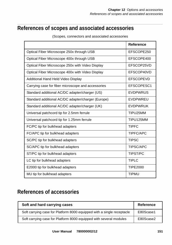
Chapter 12 Options and accessoriesReferences of scopes and associated accessories
References of scopes and associated accessories(Scopes, connectors and associated accessories
References of accessories
Reference
Optical Fiber Microscope 250x through USB EFSCOPE250
Optical Fiber Microscope 400x through USB EFSCOPE400
Optical Fiber Microscope 250x with Video Display EFSCOP25VD
Optical Fiber Microscope 400x with Video Display EFSCOP40VD
Additional Hand Held Video Display EFSCOPEVD
Carrying case for fiber microscope and accessories EFSCOPESC1
Standard additional AC/DC adapter/charger (US) EVDPWRUS
Standard additional AC/DC adapter/charger (Europe) EVDPWREU
Standard additional AC/DC adapter/charger (UK) EVDPWRUK
Universal patchcord tip for 2.5mm ferrule TIPU25MM
Universal patchcord tip for 1.25mm ferrule TIPU125MM
FC/PC tip for bulkhead adapters TIPFC
FC/APC tip for bulkhead adapters TIPFC/APC
SC/PC tip for bulkhead adapters TIPSC
SC/APC tip for bulkhead adapters TIPSC/APC
ST/PC tip for bulkhead adapters TIPST/PC
LC tip for bulkhead adapters TIPLC
E2000 tip for bulkhead adapters TIPE2000
MU tip for bulkhead adapters TIPMU
Soft and hard carrying cases Reference
Soft carrying case for Platform 8000 equipped with a single receptacle E80Scase1
Soft carrying case for Platform 8000 equipped with several modules E80Scase2
User Manual 780000002/12 151

Chapter 12 Options and accessoriesReferences of accessories
Hard carrying case for multiple module configuration E80Hcase1
Keyboard/Mouse
USB mouse E80mouse
USB QWERTY keyboard E80keyB
Compact USB keyboard for TB/MTS platforms with 2x USB ports EMINIKEYB
Soft and hard carrying cases Reference
User manual for Platform 8000 platform Reference
User manual for Platform 8000 platform (French) E8000M01
User manual for Platform 8000 platform (English) E8000M02
User manual for Platform 8000 platform (German) E8000M03
152 User Manual 780000002/12

Appendix A RoHS Information
A
This appendix describes the RoHS (Restriction of Hazardous Substances) information, which are mandatory requirements from China.The RoHS directive consists in the restriction on the use of certain hazardous substances in electrical or electronic equipment sold or used in the European Union, after July 1, 2006. These substances are: lead, mercury, cadmium, hexavalent chromium, polyubrominated biphenyls, and polybrominated diphenyl ethers.
User Manual 780000002/12 153
Appendix A RoHS InformationConcerned products : 8000 Base Unit
Concerned products : 8000 Base Unit Bn 8000 series, Bt 8000 series
“ C h in a R o H S ”
电子信息产品污染控制管理办法 (信息产业部第 39 号)
此附录提供”China RoHS”要求的产品环境使用期限和有毒有害物质名称及含量。此附录适用于主机和它的附件。 产品名称:XXXXXX 环保使用期限
此标识标注在主要产品上表示此产品或它的附件中含有有毒有害物质 (详细信息见下表)
标志中间的数字代表至生产日期起的环保最大使用年限。正常使用情况下,有
毒有害物质不会发生突变或外泄。这个期限不适用消耗品,例如电池。
正常的操作情况请参考产品的使用手册 生产日期请参考产品的校准证明正本
有毒有害物质名称及含量表识格式 有毒有害物质或元素
部件名称 铅 (Pb) 汞 (Hg) 镉 (Cd) 六价铬 (CR6+) 多溴联苯 (PBB) 多溴二苯醚(PBDE)
主机 O O O O O O 印刷电路板 X O O O O O 内部布线 O O O O O O 显示屏 O O O O O O 键盘 O O O O O O 电池 O O O O O O
电源单元 O O O O O O 机电部件 O O O O O O
硬盘 O O O O O O 光模块 O O O O O O
金属外壳部件和夹具 O O O O O O 塑料外壳部件 O O O O O O
标签 O O O O O O 附件 O O O O O O
外部电缆和适配器 O O O O O O 光驱 O O O O O O
操作手册和印刷资料 O O O O O O 软包和硬包 O O O O O O 其他附件 O O O O O O
O : 表示该有毒有害物质在该部件所有均质材料中的含量均在 SJ/T11363-2006.
X: 表示该有毒有害物质至少在该部件的某一均质材料中的含量超出 SJ/T11363-2006.
154 User Manual 780000002/12

Appendix A RoHS InformationConcerned products : 8000 Base Unit
Concerned products : 8000 Base Unit8000 Base Unit
“China RoHS”
电子信息产品污染控制管理办法 (信息产业部第 39 号)
此附录提供”China RoHS”要求的产品环境使用期限和有毒有害物质名称及含量。此附录适用于主机和它的附件。 产品名称:XXXXXX 环保使用期限
此标识标注在主要产品上表示此产品或它的附件中含有有毒有害物质 (详细信息见下表)
标志中间的数字代表至生产日期起的环保最大使用年限。正常使用情况下,有
毒有害物质不会发生突变或外泄。这个期限不适用消耗品,例如电池。
正常的操作情况请参考产品的使用手册 生产日期请参考产品的校准证明正本
有毒有害物质名称及含量表识格式 有毒有害物质或元素
部件名称 铅 (Pb) 汞 (Hg) 镉(Cd) 六价铬(CR6+) 多溴联苯(PBB) 多溴二苯醚(PBDE)
主机 O O O O O O 印刷电路板 X O O O O O 内部布线 O O O O O O 显示屏 X O O O O O 键盘 O O O O O O 电池 O O O O O O
电源单元 O O O O O O 机电部件 O O O O O O
硬盘 X O O O O O 光模块 O O O O O O
金属外壳部件和夹具 O O O O O O 塑料外壳部件 O O O O O O
标签 O O O O O O 附件 O O O O O O
外部电缆和适配器 O O O O O O 光驱 O O O O O O
操作手册和印刷资料 O O O O O O 软包和硬包 O O O O O O 其他附件 O O O O O O
O: 表示该有毒有害物质在该部件所有均质材料中的含量均在 SJ/T11363-2006.
X: 表示该有毒有害物质至少在该部件的某一均质材料中的含量超出 SJ/T11363-2006.
User Manual 780000002/12 155

Appendix A RoHS InformationConcerned products : 8000 Base Unit
156 User Manual 780000002/12

Index
AAC Adaptor
specifications 141
Accessories 147
Assembling the component parts 10
Attenuator ext. (powermeter) 73
BBatteries
access and installation 24
Batteries chargerspecifications 141use 20
Batterycharge level display 23Endurance 21on microprocessor board 126specifications 141
CCarrying handle
fitting 20
CD-ROM burning 113
Cleaning 125
Commands 33external keyboard 33
CompactFlash 133
Configuration 7instrument 50principle 50system 53
Connection to a PC 39
Connectoralso see serial port, parallel port, CEI port
Connectors 44optical connectors
cleaning 126precautions 125
VGA screen/projector 47
Control buttons 31
Control Panelfront 30
Control panelback 44
DData transfer 88, 113
Date 57
Dimensions 142, 147
Direction keys 33
User Manual 780000002/12 157

Index
EEditing 35
Environment 142
EthernetLAN parameters 59
External Keyboard 33
FFile
configuration 110
GGPL 103
Guarantee conditions 125
HHelp 53
II/O Interface 58
Indicators 33
Interfacetransfer on to a PC 41
LLanguage 32, 57
Locking 67
LTSConfiguration 72Connection 71Display 75measurement 77Principles 70source 74
MMaintenance
procedure 124
Measurementattenuation measurement 70optical link loss 70power measurement 70
Memorycapacity 140see File
Modulefitting and removing 10
OOFI
FOXmeasurement acquisition 82Zero adjustment ORL 81
Optical telephone 87configuration 61specifications 144
PPCB Battery
checking 136replacement 136
Portserial (RS 232) 46
Position of the instrument 19
Powerreference power 78
Power Metermeasurement 78
Power meterzero value 78
Printer 62
RReset the 8000 Base Unit 27
User Manual 780000002/12 158

Index
SScope 94
Display 95Settings 95
Scope feature 94
Screenlighting level 55saver 56specifications 140tactile 31TFT 31
Shutdownautomatic shutdown 62switching off the 8000 Base Unit 26
Softwareupdate
server IP address 62
Sourceconfiguration 74connection 71
Specifications 139, 147
Standalone results 65
Strap 20
Switching on 25
TTime 57
UUnit
of floppy disk or CD-ROM 46powermeter 72
Unpacking the instrument 10
USB memory stick 134
VVisible source (VFL)
connector localization 45function 86selection 50specifications 145
VNC Remote screen 90
WWavelength
powermeterselection 72
User Manual 780000002/12 159

Index
User Manual 780000002/12 160


Test and Measurement Regional Sales
North AmericaToll Free: 1 800 638 2049Tel: +1 240 404 2999Fax:+1 240 404 2195
Latin AmericaTel: +55 11 5503 3800Fax:+55 11 5505 1598
Asia PacificTel: +852 2892 0990Fax:+852 2892 0770
EMEATel: +49 7121 86 2222Fax:+49 7121 86 1222
www.jdsu.com
8000M02/UM/OPT/12-09/AERev. 12, 12-09English