80 lb rotary spreader optional equipment calibration · 80 lb rotary spreader optional equipment...
TRANSCRIPT

80 LB Rotary SpreaderOptional EquipmentCalibration
PARTS LIST AND INSTRUCTIONS
705698/Carbon Steel, 705699/Stainless Steel
5:1 Gearbox
Model #: 705698 / 705699
Starting Date: 8/2002-
This product may be covered by one or more of the following patents:4,511,090, Pending

80LB. Hopper Assembly - Figure 1 and Parts List
4
7
2
12
13
1
7
4
14
5
12
18
11
17
19
15
8
63
8
9
16
20
7
710
The OptionalJet-Action DeflectorLESCO No. 706657
Ref. No.
PartNo. Description Qty.
1 031168 Screw, 1/4-20 x .75 22 060036 Lock Nut, 1/4-20 33 061066 Deflector 14 060057 Screw, 1/4-20 x 7/8 15 061052 Cotter Pin 16 061053 Flat Washer 17 706254 Mounting Tube 18 706305 Handle 19 706308 Ring Support 1
4
2
9
1
3
8
7
6
5
2
Ref. No.
PartNo. Description Qty.
Ref.No
PartNo Description Qty.
1 005530 Nylon Flat Washer, 3/8 1 11 706772 Control Plate Rate 12 706696 Screen 1 12 060046 Screen Clip 23 030322 Agitator Assembly 1 13 060049 Agitator Arm Assembly 14 031167 Hex Cap Screw, 1/4-20, 1.50 4 14 060050 3/8 Retainer Spring Clip 15 706895 Lesco Decal, 2-3/8 x 7-1/8 1 15 060057 1/4 -20 x 7/8 Pan Head Mach Screw 16 060027 Agitator Shaft Bearing 1 16 700128 Nylon Flat Washer, .26 x .687 x .06 27 060033 Flat Washer, 1/4” 4 17 702048 4” x 2” Vinyl Decal 18 060036 Nylock Nut, 1/4-20 5 18 704959 Hopper Green 19 060043 Control Rate Knob 1 19 705631 Index Washer Hex Screw, #8 x 3/8 210 060044 Control Arm Rate 1 20 090006 Decal, USA 1
2
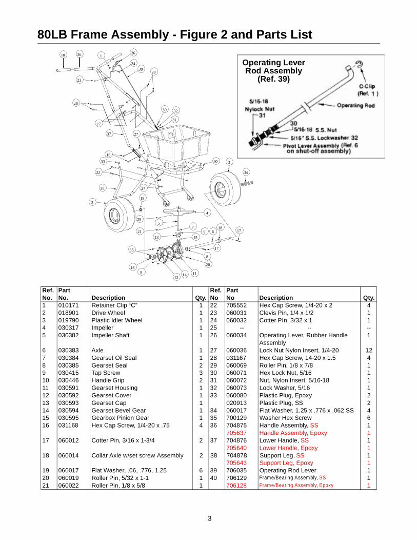
80LB Frame Assembly - Figure 2 and Parts List
Ref. No.
PartNo. Description Qty.
Ref.No
PartNo Description Qty.
1 010171 Retainer Clip “C” 1 22 705552 Hex Cap Screw, 1/4-20 x 2 42 018901 Drive Wheel 1 23 060031 Clevis Pin, 1/4 x 1/2 13 019790 Plastic Idler Wheel 1 24 060032 Cotter PIn, 3/32 x 1 14 030317 Impeller 1 25 -- -- --5 030382 Impeller Shaft 1 26 060034 Operating Lever, Rubber Handle
Assembly1
6 030383 Axle 1 27 060036 Lock Nut Nylon Insert, 1/4-20 127 030384 Gearset Oil Seal 1 28 031167 Hex Cap Screw, 14-20 x 1.5 48 030385 Gearset Seal 2 29 060069 Roller Pin, 1/8 x 7/8 19 030415 Tap Screw 3 30 060071 Hex Lock Nut, 5/16 110 030446 Handle Grip 2 31 060072 Nut, Nylon Insert, 5/16-18 111 030591 Gearset Housing 1 32 060073 Lock Washer, 5/16 112 030592 Gearset Cover 1 33 060080 Plastic Plug, Epoxy 213 030593 Gearset Cap 1 020913 Plastic Plug, SS 214 030594 Gearset Bevel Gear 1 34 060017 Flat Washer, 1.25 x .776 x .062 SS 415 030595 Gearbox Pinion Gear 1 35 700129 Washer Hex Screw 616 031168 Hex Cap Screw, 1/4-20 x .75 4 36 704875 Handle Assembly, SS 1
705637 Handle Assembly, Epoxy 117 060012 Cotter Pin, 3/16 x 1-3/4 2 37 704876 Lower Handle, SS 1
705640 Lower Handle, Epoxy 118 060014 Collar Axle w/set screw Assembly 2 38 704878 Support Leg, SS 1
705643 Support Leg, Epoxy 119 060017 Flat Washer, .06, .776, 1.25 6 39 706035 Operating Rod Lever 120 060019 Roller Pin, 5/32 x 1-1 1 40 706129 Frame/Bearing Assembly, SS 121 060022 Roller Pin, 1/8 x 5/8 1 706128 Frame/Bearing Assembly, Epoxy 1
10
23
37
33
38
219
4
7
159
40
29
21
5
13
18
35
8
34
3
6 17
17
8
20
111412
18
27
22
16
27
28
36 126
3924
31
3230
27
28
Operating LeverRod Assembly
(Ref. 39)
3
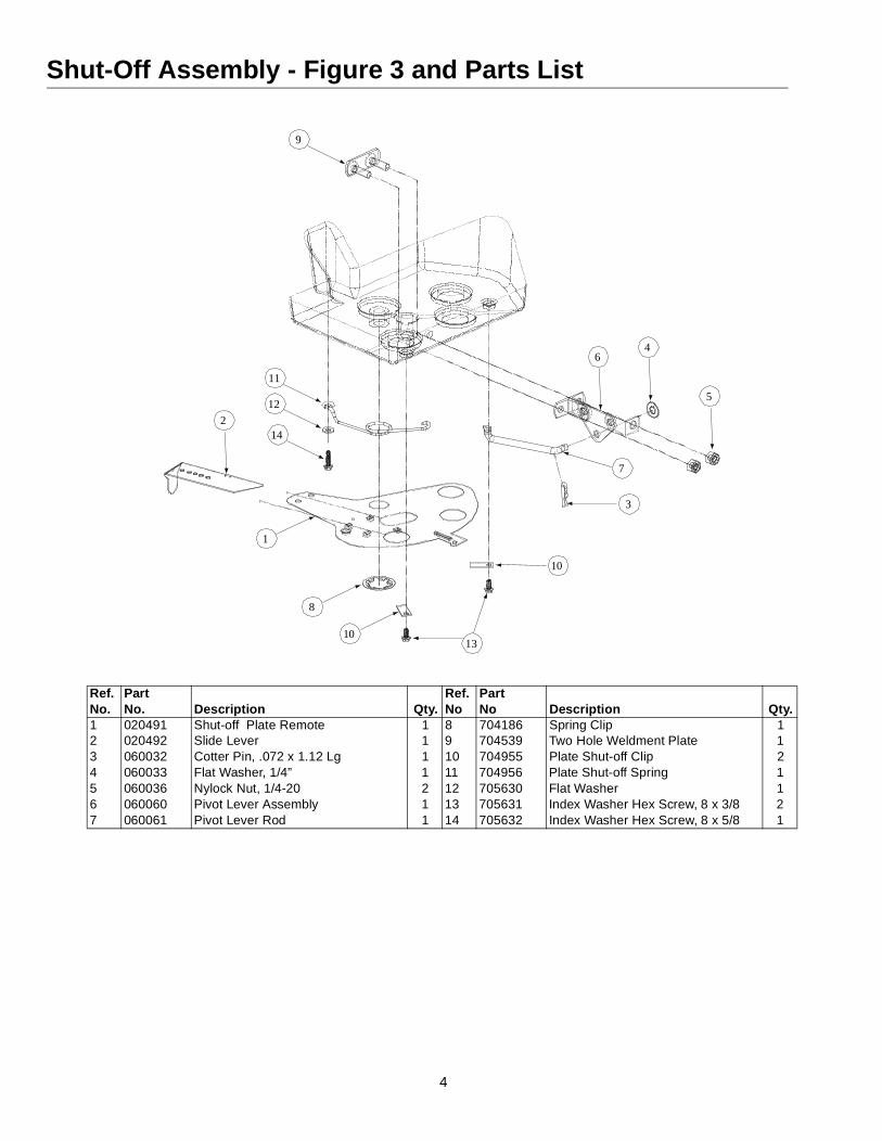
Shut-Off Assembly - Figure 3 and Parts List
Ref. No.
PartNo. Description Qty.
Ref.No
PartNo Description Qty.
1 020491 Shut-off Plate Remote 1 8 704186 Spring Clip 12 020492 Slide Lever 1 9 704539 Two Hole Weldment Plate 13 060032 Cotter Pin, .072 x 1.12 Lg 1 10 704955 Plate Shut-off Clip 24 060033 Flat Washer, 1/4” 1 11 704956 Plate Shut-off Spring 15 060036 Nylock Nut, 1/4-20 2 12 705630 Flat Washer 16 060060 Pivot Lever Assembly 1 13 705631 Index Washer Hex Screw, 8 x 3/8 27 060061 Pivot Lever Rod 1 14 705632 Index Washer Hex Screw, 8 x 5/8 1
9
11
12
142
1
8
1013
10
7
3
64
5
4

9
Ref. No. Part No. Description Qty.1 010171 Retainer “C” Clip 12 018628 Nylon Washer, 1/4 63 030503 Deflector Arm Mount Spacer 14 035030 Offset Bracket Deflector 15 060029 Machine Screw, 1/4-20x2 26 060033 Flat Washer, 1/4” 17 060034 Operating Lever and Rubber 18 060036 Lock Nut, Nylon Insert, 1/4 89 060057 Machine Screw Pan Head, 1/4-20x7/8 610 060059 Hex Nut, 1/4-20 111 060071 Hex Lock Nut, 5/16-18 112 060072 Nut, Nylon Insert, 5/16-18 113 060073 Lock Washer, 5/16 114 061052 Cotter Pin, 1/8 x 1 115 061053 Flat Washer, 3/8 116 061066 Deflector Tube, Plastic Only 117 -- -- --18 -- -- --19 706251 Deflector Actuator Rod 120 706252 Lever Rod Deflector Bracket 121 706253 Tube Bracket Mount, Lever, Deflector 122 706254 Deflector Tube Mount 123 030418 Remote Bracket 1
81
7
23
2
8
14
12
19
9
11
15
13
20
8
8
229
9
5 32
6
10
9
16
8
4
2 221
NOTE: Adjust the friction at the three deflector arm pivot points by tightening the nuts and then backing them off 1/8th turn. Ad-just the friction at the operating lever pivot so that it will hold its position.
Mounting Instructions1. Install the deflector tube mount (ref. 22) onto the right
side of the spreader frame (from the inside) as shown.2. Install the tube bracket mount (ref. 21) to the right side
of the frame using appropriate hardware as shown.a. Install 1/4-20 x 2 (ref. 5) through frame plate using
spacer (ref. 3), washer (ref. 6), and tighten using 1/4-20 nut (ref. 10).
b. Install nylon washer (ref. 2), bracket mount (ref.21) nylon washer (ref 2) and tighten nut (ref. 8) until bracket mount (ref. 21) easily turns.
3. Install offset bracket (ref. 4) onto deflector (ref.16) a. Slide Long end of offset bracket into slot on
deflector (ref.16)b. Install 1/4-20 screw (ref. 9) and tighten sub
assembly using 1/4-20 nut (ref. 8)
4. Slide deflector subassembly onto deflector tube mount(ref. 22)
a. Install washer (ref. 15) onto deflector tube mount and lock in place using cotter pin (ref. 14)
5. Fasten offset bracket (ref. 4) to bracket mount (ref. 21)using appropriate hardware.
a. Install 1/4-20 screw (ref. 9) and tighten sub assembly using 1/4-20 nut (ref. 8) until deflector (ref. 16) moves easily on deflector tube mount (ref. 22)
6. Install lever rod bracket (ref. 20) to bracket mount (ref. 21).
a. Install, making sure small flange of lever rod bracket faces to the inside of the spreader, using appropriate hardware.
7. Install remote bracket (ref. 23) onto right side of upperhandle.
a. Install using one 1/4-20 (ref. 5) and one 1/4-20 nut (ref. 8)
8. Install operating lever (ref. 7) using appropriatehardware
9. Install rod (ref. 19) into operating lever (ref. 7) and intolever rod bracket (ref. 20)
10. Slide deflector up toward the bottom of the hopper asfar as it will go.
11. Place the operating lever (ref. 7) i the “OFF” positionand adjust the lock nut (ref. 11) so it is down againstthe lever rod bracket (ref. 20).
a. Tighten nylock nut (ref. 12) up against the underside of the lever rod bracket (ref. 20)
Drill 9/32" Hole
Right Handle
9.5
The Optional Remote Deflector - Part No. 706250
5

The Optional Remote 3rd Hole Slide - LESCO No. 030571
Mounting Instructions1. Mount the dual lever bracket (Ref. 1) to the right
handle using one machine screw (Ref. 2), one flat washer (Ref. 3) and one hex nut (Ref. 4) as shown below.
2. Mount the dual remote lever (Ref. 5) to the dual lever bracket (Ref. 1) using one machine screw (Ref. 6), two nylon flat washers (Ref. 7) and one hex nut (Ref. 4) as shown below.
3. Slide the control cable (Ref. 8) through the hole in the dual remote lever and the cable housing into the fork of the dual lever bracket and pinch the forks around the cable groove.
4. With the dual remote lever pushed all the way forward attach the other end of the control cable to the hole in the 3rd hole slide. Push the slide fully closed and mount the cable housing to the shut off plate using the cable clamp (Ref. 9), two machine screws (Ref. 10), two lock washers (Ref. 11) and two hex nuts (Ref. 12) as shown below.
5. Work the dual remote lever back and forth to be sure that you are getting the full open and full closed positions of the 3rd hole slide. If not, loosen the cable clamp and adjust the cable.
6
Parts ListRef. No. Part No. Description Qty.
1 030418 Bracket, Dual Lever 12 060047 Machine Screw 13 060033 Flat Washer 1/4 14 060036 Hex Nut, 1/4-20 Nylock 25 030416 Lever, Dual Remote 16 060057 Machine Screw 17 018628 Flat Washer, 1/4 Nylon 28 030450 Control Cable 19 020511 Cable Clamp 1
10 031686 Machine Screw 211 060083 Lock Washer #8 212 060056 Hex Nut, #8-32 2
Impeller Shaft SupportBottom of Hopper

Rotary Spreaders - Assembly Instructions
1. Remove the spreader components from the screws, 1/4-2 x 1 1/2 and 4 nylock nuts, 1/4-20.
Hopper and Frame
Handle Grips
Handle
On/Off Lever
Operating Lever Rod
Lower Handle
Leg
carton. You should find all of the parts shown above plus the Hardware Package. The Hardware Package contains:
2. Install the leg to the hopper and frame assembly by fastening with 4 Phillips head machine screws, 1/4-20 x 2 and 4 locknuts, 1/4-20.
3. Attach the lower handle to the frame (with the “V” section of the closed section of the handle facing down) using 4 hex head screws, 1/4-20 x 3/4, and 4 nylock nuts, 1/4-20. nuts, 1/4-20.
4. Attach the upper handle to the lower handle (with the on/off bracket lugs facing up) using 4 machine
1 C-Clip1 Calibration Gauge (ODD)1 Calibration Gauge (EVEN)1 Calibration Gauge Chain1 Clevis Pin, 1/4 x 1/21 Cotter Pin, 3/32 x 11 Hex Nut, 5/16-181 Hex Nut, 5/16-18, Nylock1 Lock Washer, 5/164 Machine Screw, 1/4-20 x 2”4 Machine Screw, 1/4-20 x 1-1/2"4 Hex Screw, 1/4-20 x 3/4”12 Nylock Nut, 1/4-20
7
5. Fasten the on/off lever to the handle's bracket lugs using the clevis pin in the bottom hole of the lever. Insert the clevis pin from left to right, facing the rear of the hopper. Lock with the 3/32 x 1/2 cotter pin.
6. Attach the operating lever rod to the pivot lever assembly at the bottom-rear of the hopper. First screw the 5/16 hex nut on the threaded end of the operating lever rod, add the 5/16 lock washer, then insert the rod through the hole in the pivot lever assembly and install the 5/16 locknut.
7. Attach the operating lever rod to the on/off lever by inserting the bent end of the rod into the top hole of the lever from left to right and install the C-clip.
8. Pull the on/off lever to the off position and move the shutoff plate assembly to the fully closed position by adjusting the 5/16 hex nuts on the bottom of the operating lever rod.
9. Place the handle grips on the handles.10. Grease the axle bearings and the gear support.11. Read the Lesco Spreader Calibration instructions
packed with your spreader and calibrate following the instructions.
Spreader Calibration
Spreader calibration is simplified using the LESCO Professional Granular Applicator Calibration Kit LESCO No. 011900.Two items must be considered when calibrating a spreader. The first is the distribution pattern of the spreader. That is, the pattern the prod-uct makes as it strikes the ground after being thrown out by the spreader's impeller. There are many factors which affect the distribu-tion pattern of a rotary spreader and some of them relate directly to the product. For this reason, we recommend that the spreader be cal-ibrated separately for every product to be applied. Spreader calibra-tion should be checked at least once a month, or more often when the spreader is used frequently.The second item is the product application rate, that is the amount of product applied per thousand square feet. This is important because over-application can be costly and may cause plant injury, while un-der-application will reduce the effectiveness of the product.
TO CALIBRATE A SPREADER, FOLLOW THESE STEPS:Check the spreader discharge holes with the operating lever in the closed position. If the discharge holes are not fully closed, thread the upper jam nut on the operating lever rod further up the rod. Tighten the lower locknut and recheck. Repeat this procedure until the holes are fully closed.
TO ACHIEVE A UNIFORM DISTRIBUTION PATTERN:
The accurate method for checking pattern uniformity is to lay out shal-low boxes or pans in a row on a line perpendicular to the direction of spreader travel. Eleven boxes or pans, two inches high placed on one-foot centers will provide accurate calibration. To conduct the test, begin with the pattern slide completely open and set the rate control arm at the suggested approximate setting. Make three passes over the boxes, pushing the spreader in the same direction each time. The product caught in each box is then evaluated to determine the distri-bution pattern. Weighing the product in each box is the most accurate, but a simpler method is to pour the contents of each box into a sepa-rate small vial or bottle. Then set the eleven vials or bottles side-by-side in order. This makes the pattern variation quite visible.
To reduce the amount of discharge to the right side (operator's right) the pattern slide should be partially closed and the test repeated until the distribution pattern is uniform.
TO ACHIEVE THE CORRECT PRODUCT APPLICATION RATE:
The approximate spreader settings printed on any product label should only be used as the initial setting for calibration. Set the rate control arm at this approximate setting. Using the collection boxes or pans, make a single pass over them to determine the effective pattern width. The effective pattern width is twice (2x) the distance to the point where the rate drops to one-half the average rate at the center. Ex-ample: If the product in the vials from the center boxes averages two inches in depth, count out to the vial which has one inch of product. If this is the fifth vial from the center and the boxes were on one-foot centers, the effective pattern width is ten feet (2 x 5 ft.).
Knowing the effective pattern width (ten feet), measure out a lineal distance to equal 1,000 sq. ft. (10 ft. x 100 ft. = 1,000 sq. ft.). Weigh 20 lbs. of product and place it in the spreader hopper and spread it over the distance necessary to equal 1,000 sq. ft. (100 ft.). Then weigh the product left in the hopper and subtract this amount from the amount with which you started. The result is the application rate for this product in pounds per 1,000 sq. ft. that your spreader is currently adjusted to disperse. Adjust the rate control arm up or down as need-ed and repeat this procedure until the correct application rate is achieved.
8
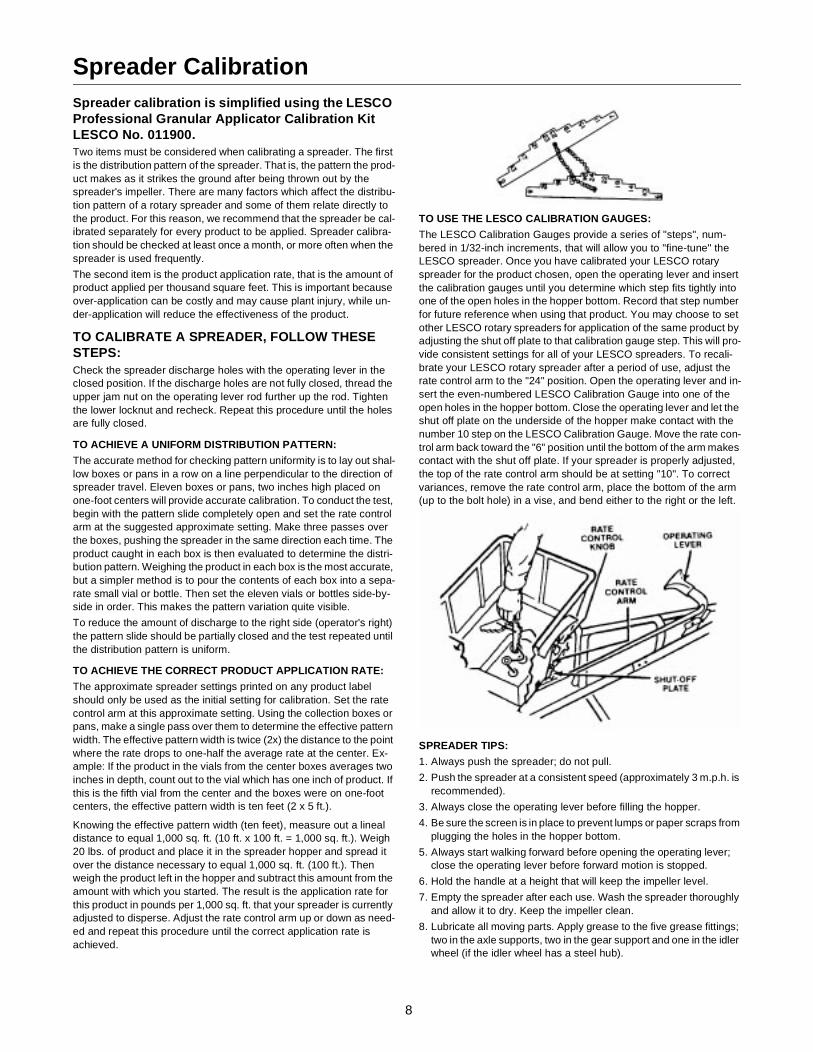
TO USE THE LESCO CALIBRATION GAUGES:
The LESCO Calibration Gauges provide a series of "steps", num-bered in 1/32-inch increments, that will allow you to "fine-tune" the LESCO spreader. Once you have calibrated your LESCO rotary spreader for the product chosen, open the operating lever and insert the calibration gauges until you determine which step fits tightly into one of the open holes in the hopper bottom. Record that step number for future reference when using that product. You may choose to set other LESCO rotary spreaders for application of the same product by adjusting the shut off plate to that calibration gauge step. This will pro-vide consistent settings for all of your LESCO spreaders. To recali-brate your LESCO rotary spreader after a period of use, adjust the rate control arm to the "24" position. Open the operating lever and in-sert the even-numbered LESCO Calibration Gauge into one of the open holes in the hopper bottom. Close the operating lever and let the shut off plate on the underside of the hopper make contact with the number 10 step on the LESCO Calibration Gauge. Move the rate con-trol arm back toward the "6" position until the bottom of the arm makes contact with the shut off plate. If your spreader is properly adjusted, the top of the rate control arm should be at setting "10". To correct variances, remove the rate control arm, place the bottom of the arm (up to the bolt hole) in a vise, and bend either to the right or the left.
SPREADER TIPS:
1. Always push the spreader; do not pull.
2. Push the spreader at a consistent speed (approximately 3 m.p.h. is recommended).
3. Always close the operating lever before filling the hopper.
4. Be sure the screen is in place to prevent lumps or paper scraps from plugging the holes in the hopper bottom.
5. Always start walking forward before opening the operating lever; close the operating lever before forward motion is stopped.
6. Hold the handle at a height that will keep the impeller level.
7. Empty the spreader after each use. Wash the spreader thoroughly and allow it to dry. Keep the impeller clean.
8. Lubricate all moving parts. Apply grease to the five grease fittings; two in the axle supports, two in the gear support and one in the idler wheel (if the idler wheel has a steel hub).

Notes
9

Notes
10

Notes
11

)
ects
.
S
ing
ement
rt or
ROTARY SPREADER ONE-YEAR LIMITED WARRANTY1. What Is Covered By This Warranty. LESCO, Inc. warrants, to the original purchaser only, that the Equipment that is the subject of this sale (aconforms to LESCO’s published specifications, and (b) is free from defects under normal service, for a one-year period from the original date of delivery. This warranty does not include damage to the Equipment resulting from occurrences set forth hereinafter in (2). If the purchaser discovers within this period a failure of the Equipment to conform to specifications or a defect in material or workmanship, they must promptly notify LESCO in writing of such claim. Any claims under this warranty must be received in writing by LESCO within 13 months from the date of original delivery. Within a reasonable time after such notification, LESCO will replace any defective component of the Equipment or part thereof. LESCO will provide the components or parts at LESCO’s expense. Labor is to be performed by the original purchaser. (LESCO will provide purchaser a labor allowance at LESCO’s current flat rate schedule.) LESCO will make the final determination as to the amount of hours to be reimbursed to the purchaser for labor. All defective parts shall be returned to LESCO if requested. These remedies are the original purchaser’s exclusive remedies for breach of warranty.
2. What Is Not Covered By This Warranty. LESCO does not warrant (a) any product, components or parts not manufactured by LESCO; (b) defcaused by failure to provide a suitable installation environment for the Equipment; (c) damage caused by use of the Equipment for purposes other than those for which it was designed; (d) damage caused by accident or disasters such as fire, flood, wind and lightning; (e) damage caused by unauthorized attachments or modification; or (f) any other abuse or misuse of the Equipment.
3. EXCLUSIVE WARRANTY. THE FOREGOING WARRANTY IS EXCLUSIVE AND IN LIEU OF ALL OTHER WARRANTIES OR REMEDIES, WHETHER WRITTEN, ORAL OR IMPLIED. ANY AND ALL IMPLIED WARRANTIES OF MERCHANTABILITY, FITNESS FOR A PARTICULAR PURPOSE, COURSE OF DEALING OR USAGE OF TRADE ARE HEREBY EXPRESSLY DISCLAIMED AND EXCLUDED
4. LIMITATION OF REMEDIES. UNDER NO CIRCUMSTANCES, EXCEPT TO THE EXTENT PROHIBITED BY APPLICABLE LAW, SHALL LESCO BE LIABLE FOR ANY LOSS OR DAMAGE, DIRECT OR INDIRECT, SPECIAL, INCIDENTAL OR CONSEQUENTIAL ARISING OUT OF THE USE OF OR INABILITY TO USE THIS EQUIPMENT INCLUDING BUT NOT LIMITED TO ANY CLAIM FOR LOSS OF PROFITS, LOSS OF SAVINGS OR REVENUE, LOSS OF USE OF THE EQUIPMENT OR ANY ASSOCIATED EQUIPMENT, FACILITIEOR SERVICE, DOWNTIME, THE CLAIMS OR COSTS OF THIRD PARTIES INCLUDING CUSTOMERS, AND INJURY TO PROPERTY.Some states do not allow limitations on how long an implied warranty lasts or the exclusion or limitation of incidental or consequential damages, so theabove limitations or exclusion may not apply to you. This warranty gives you specific legal rights, and you may also have other rights which vary from state to state.
5. Time Limit For Claims. Any claim for breach of warranty or claims under this warranty must be received by LESCO within 13 months followdelivery of the equipment.
6. No Other Warranties. Unless modified in writing signed by both parties, this agreement is understood to be the complete and exclusive agrebetween the parties, superceding all prior agreements, oral or written, and all other communications between the parties relating to the subject matter of this agreement. No employee or representative of LESCO or any other party is authorized to make any other Warranty or to assume any other liability in connection with the sale of its Equipment.
7. Future Changes. LESCO reserves the right to reserve, change or modify the construction and design of its Equipment or any component paparts thereof without incurring the obligations to make such changes or modifications in present equipment.
8. Allocation Of Risks. This agreement allocates the risks of equipment failure between LESCO and the original purchaser. This allocation is recognized by both parties and is reflected in the price of the goods. THE PURCHASER ACKNOWLEDGES THAT IT HAS READ THIS AGREEMENT, UNDERSTANDS IT, AND IS BOUND BY ITS TERMS.
9. How To Contact LESCO. If during the warranty period, the LESCO Rotary Spreader does not function properly due to defect, simply contact the LESCO Service Department:
LESCO, Inc. (440) 783-9250 ClevelandService Department (800) 321-5325 Toll FreeP.O. Box 368000Strongsville, OH 44136-9998
HOW TO ORDER PARTSContact your LESCO Salesperson, OR phone us (use the numbers above), OR write us (use the address above). We will need the following information:
1. Your account number if available.2. Your name and address and the address where you want the parts to be shipped. 3. The Model/Serial No. of the equipment.4. The LESCO Part No. and the quantity desired. (Please do not use reference numbers.)
NOTE: Inspect all shipments on receipt for damage or missing parts. File a claim with the carrier before accepting a damaged shipment.
We reserve the right to change designs, specifications and equipment at any time without notice and without incurring any obligations.
LESCO, Inc., 15885 Sprague Road, Strongsville, Ohio 44136Toll Free (800) 321-5325 • In the Cleveland Area (440) 783-9250
Form No. 706658 Rev. 02-3AC 6/8/2002 © Copyright 2002 - LESCO, Inc.LESCO is a registered trademark of LESCO Technologies, LLC.