8 water treatment for contemporary hemodialysis
TRANSCRIPT

8
WATER TREATMENT FOR CONTEMPORARY HEMODIALYSIS
BERNARD J.M. CANAUD and CHARLES M. MION
Rationale for water treatment in iiemodialysis Water contaminants Water treatment devices
Activated carbon filters Distillation Softening Filtration Ultrafiltration Reverse osmosis (RO) Deionization Ultraviolet radiation treatment
Water treatment system concept Water pre-treatment and purification systems Water storage
231 232 234 234 236 237 238 239 239 240 242 242 243 245
Water and dialysate distribution system Final filtration
Water treatment system maintenance and hygiene of dialysis
Disinfection Filter and resin changes Biofilm synthesis and destruction
Water treatment quality control Chemical purity Microbiological purity
Water standards for contemporary dialysis Conclusions References
246 246
247 247 247 247 249 249 250 250 251 251
RATIONALE FOR WATER TREATMENT IN HEMODIALYSIS
Maintenance hemodialysis is an accepted life support system ensuring long term survival of half a million end stage renal failure patients worldwide. Hemodialysis patients are regularly exposed to 300-400 liters of hemodialysis fluids per week during dialysis. The quality of water used to dilute the concentrated dialysate fluid is important because of the nature of the contact between dialysate and the patient's blood. The end stage renal failure patient is the last link of a complex chain leading to the hemodialysis process, where patient's blood is exposed to dialysate. One can look at the hemodialysis system as the end point of an hydraulic circuit where city water is changed in water for HD through municipal water supply, water treatment system, distribution system and delivering dialysate through the artificial kidney (Figure 1).
From the early days of dialysis it is known that water used for hemodialysis must be purified in order to prevent clinical side effects due to contamination of water (1-4). Water for dialysis must be considered as a pharmaceutical product exposed to patient's blood system requiring a specific and more stringent purification approach (5-7). Drinking regulation standards for water are based on a weekly exposure of 14 liters with a selective gut barrier. Hemodialysis patients are exposed to 300-400 liters per week through a non-selective artificial dialyzer membrane. Furthermore, dialysis patients having non urinary excretion capacity are exposed to higher risk of toxic substances accumulation particularly for those who are bound to protein and/or tissue. Contemporary dialysis
has introduced new risks directly related to the quality and purity of water used in dialysis (8-11). Hemodialysis using highly permeable membrane and ultrafiltration controller is responsible for backfiltration and/or backdif-fusion from dialysate (12-17). On the one hand, such an unapparent convective transport phenomenon is capable of transferring toxic and/or pyrogenic substances from dialysate to blood resulting in febrile reaction (18-21). On the other hand, dialysate contaminants may contribute to the activation of various protein systems, enzymes and cells circulating in the blood compartment (22, 23). Inline production of substitution fluid used in some dialysis modalities (e.g., in-line hemofiltration, HF or hemodi-afiltration, HDF) infuse a large fraction of dialysate fluid dhectly into the patient's blood stream enhancing risks for direct toxicity and/or pyrogenicity (24, 25). Dialyzer reconditioning using water from the dialysis unit is associated with hazards of introducing pyrogenic material and/or bacteria within the lumen of the dialyzer fibers (26-35). Water treatment system therefore must provide the dialysis facility and the hemodialysis machine with a pure water which has been cleared from all contaminants (36-38),
Water purity requirements have changed over the past three decades. Hemodialysis has been used routinely as maintenance therapy in end stage renal disease patients for thirty years. Schematically, water purity has considerably improved according to a three stage periods.
The first decade (1960-1970) was a pioneering period. The objectives were essentially the development of dialysis program in order to ensure survival of end stage renal failure patients. Water treatment system used during this

232 Bernard J.M. Canaud and Charles M. Mion
1. Water supply Municipal water supply
Charcoal r-Pm-treatmmt Fllteriii|»SoftenerMJ|. j j^^^ Ji-iMcrofliter
2. Water treatment
L Primary treatment Ultrafllter Delontzer
Reverse ' osmosis
L. PosMreatment storage tank Sabmicronic filter charged*
3. Distribution system
4. Dialfsate delivery
w H l i IP
Hemodialysis tacility
Figure 1. Schematic representation of the different steps of the water purification system, starting from the municipal water supply and ending at the dialysate delivery system.
period was basically designed to remove colloid particulates, calcium, magnesium, chlorine and toxic substances in order to prevent mainly 'haxd water syndrome' and also to prevent pyrogenic reactions. Indeed, from the early Seattle experience, it was shown that the bacteriologic contamination of the dialysis iuid was a potential risk for the hemodialysis patient (39).
The second decade (1970^1980) revealed the hazards of various substances added to city water to control turbidity (aluminium sulfate) or bacteriologic contamination (chlorine, chloramine). Aluminium intoxication revealed by the epidemic occurrence of 'dialysis dementia' was particularly stressed (40-44), Water treatment system improvement consisted in generalizing the use of reverse osmosis system and/or the deionizers (mixed beds) to prevent the rislc of aluminium intoxication, and activated charcoal to remove chlorine and chloramine from city water (45-49).
The third decade (1980-1990) was characterized by the introduction of major changes in hemodialysis technology. Bicarbonate dialysis, highly permeable membranes, ultrafiltration controllers were soon identified as new hazards requiring a higher degree of water purity with reduced bacteriologic and endotoxin contamination (8). In this context, water became a component of the complex problem hemodialysis hemocompatibility. The Interleukin-i
hypothesis was the starting point of a new research area in water and dialysate purity leading to the use of ultrapure water and dialysate in hemodialysis (22),
In this chapter, the various water puriication options available to the dialysis practionner will be described. Details will be provided concerning the nature of water treatment systems, the physical principles involved, and the monitoring approach necessary to optimize water treatment production for hemodialysis. The quality standards required to satisfy contemporary dialysis needs and to ensure patient's safety on a long term basis will also be discussed.
WATER CONTAMINAHTS
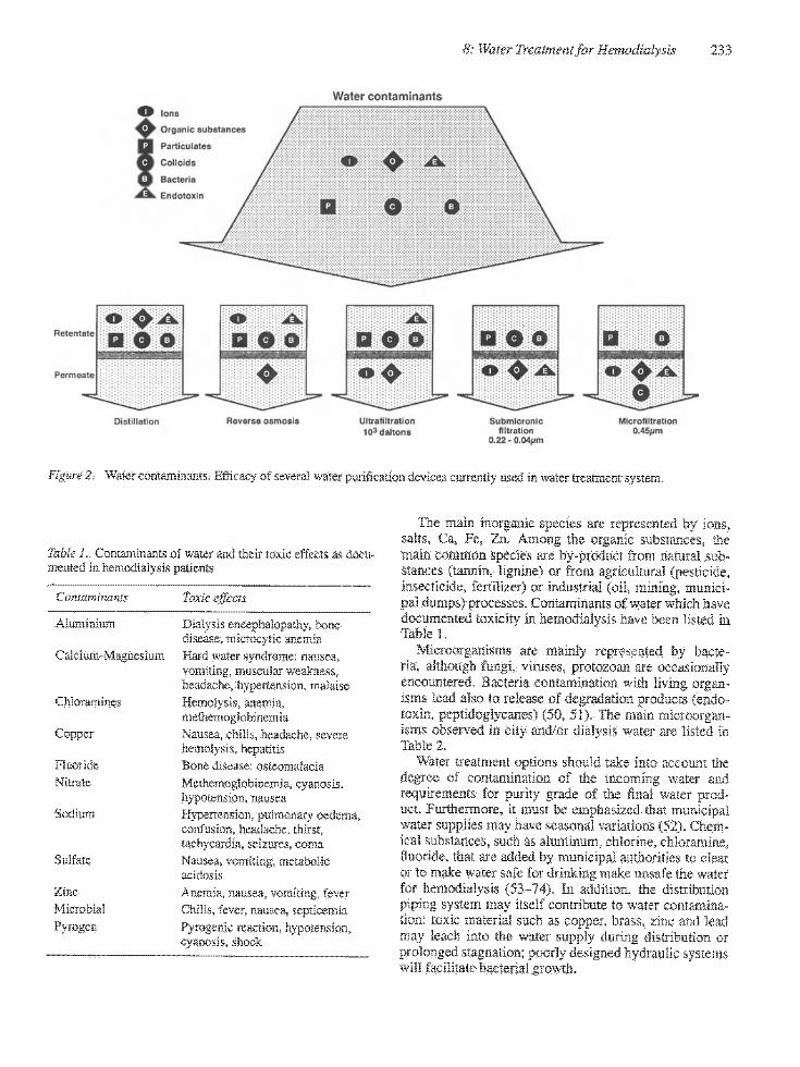
There are three major groups of water contaminants: particulates, dissolved substances and microorganisms which are presented in Figure 2.
Depending on the source, water will contain varying amounts of particulates, TTiese particulates are responsible for water turbidity: they include minerals (clay, sand, iron) or coUoids (silica soluble or polymerised).
Dissolved substances are inorganics or organics, microorganisms and pyrogens.
8: Water Treatment for Hemodialysis 233
Water contaminants
Reteitale
Permeate
Heyerse osmosis yitiBliltraliOtt M'daf tons
Submicronic fiifration
0.22 - 0.04|jiii
MIcroiltratlon i.45jinti
Figure 2. Water contaminants. Efficacy of several water purification devices cuirently used in water treatment system.
Table 1. Contaminants of water and tlieir toxic effects as documented in hemodialysis patients
Contaminants
Aluminium
Calcium-Magnesium
Chloramines
Copper
Fluoride Nitrate
Sodium
Sulfate
Zinc Microbial Pyrogen
Toxic effects
Dialysis encephalopathy, bone disease, microcytic anemia Hard water syndrome: nausea, vomiting, muscular wealcness. headache, hypertension, malaise Hemolysis, anemia. methemoglobinemia Mausea, chills, headaclie, severe hemolysis, hepatitis Bone disease: osteomalacia Methemoglobinemia, cyanosis, hypotension, nausea Hypertension, pulmonary oedema. confusion, headache, thirst, tachycardia, seizures, coma Nausea, vomiting, metabolic acidosis Anemia, nausea, vomiting, fever Chills, fever, nausea, septicemia Pyrogenic reaction, hypotension. cyanosis, shock
The main inorganic species are represented by ions, salts, Ca, Fe, Zn. Among the organic substances, the main commoa species are by-product from natural substances (tannin, lignine) or from agricultural (pesticide, insecticide, fertilizer) or industrial (oil, mining, municipal dumps) processes. Contaminants of water which have documented toxicity in hemodialysis have been listed in Table 1.
Microorganisms are mainly represented by bacteria, although fungi, yinises, protozoan are occasionally encountered. Bacteria contamination with living organisms lead also to release of degradation products (endotoxin, peptidoglycanes) (50, 51). The main microorganisms observed in city and/or dialysis water are listed in Table 2.
Water treatment options should take into account the degree of contamination of the incoming water and requirements for purity grade of the final water product. Furthermore, it must be emphasized that municipal water supplies may have seasonal yaiiations (52). Chemical substances, such as aluminum, chlorine, chloramine, iuoride, that are added by municipal authorhies to clear or to make water safe for drinking make unsafe the water for hemodialysis (53-74). In addition, the distribution piping system may itself contribute to water contamination: toxic material such as copper, brass, zinc and lead may leach into the water supply during distribution or prolonged stagnation; poorly designed hydraulic systems will facilitate bacterial growth.
234 Bernard J.M. Canaud and Charles M. Mion
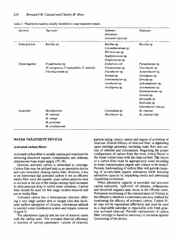
Table 2. Waterbome bacteria usually identified in water treatment system
Bacteria Tap water Softeners Deionizers Activated charcoal
Dialysate
Gram positive
Gram negative
Anaerobic
Bacillus sp.
Pseudomonas sp. {P. aeruginosa, P. mattophilia, P. cepacia) Flavobacterium sp.
Mycobacteria M. chelonei M. xenopi M. gordonae M. scrofulaceum
Bacillus sp. Corynebacterium sp. Micrococcus sp. Staphylococcus sp. Streptococcus sp. Eschericia coli Pseudomonas sp. Flavobacter sp. Serratia sp. Achromobacter sp. Aerobacter sp. Alcaligenes sp.
Clostridium sp. Mycobacter sp.
Bacillus sp.
Pseudomonas spt Flavobacter sp. Acinetobacter sp. Alcaligenes sp. Erwinia sp. Achromobacter $p. Aeromononas sp. Xamhomononas sp. Serratia sp. Moraxella sp. Klebsiella sp. Enterobacter cloacae M. chelonei M. chelonei-like
WATER TREATMENT DEVICES
Activated carbon filters
Activated carbon filter is usually used as pre-treatment for removing dissolved organic contaminants and chlorine, chloramines from water supply (75-78).
Granular activated carbon is embedded in cartridge. Carbon filter may be utilized both as an adsorptive device and a pre-treatment clearing media filter. However, it has to be mentioned that activated carbon is not an efficient media filter since the equally sized carbon particles tend to occlude at the top of the media causing rapid increases in delta pressure drop in turbid water situations. Carbon filter should be used for first stage oxident removal and not as media filter.
Activated carbon has a microporous structure offering a very large surface area to weight ratio that facilitates surface adsorption of chlorine, chloramine utilized to sanitize water distribution system and organic removal (Figure 3).
The adsorption capacity and the rate of removal varies with the carbon used. The activated charcoal efficiency is function of various parameters: volume of charcoal,
particle sizing, source, nature and degree of activation of charcoal. Overall efficacy of charcoal filter, is depending upon cartridge geometry, incoming water flow ind content of chlorine and chloramines. Regarding thf proper configuration of carbon filter the most critical factor is the water contact time with the charcoal bed. The choice of a carbon filter must be appropriately sized according to water contamination degree and volume to b0 treated. Periodic backwashing of carbon filter will permilt cleansing of accumulated organic substances while restoring adsorptive capacity by unpacking media and pneventing chaimeling occurrence.
When adsorptive capacity is exceeded and activated carbon exhausted, 'spill-over' of chlorine, chloramines and dissolved organics may occur in the effluent water. Permanent monitoring of the concentration of chlorine in the effluent is therefore a convenient and easy method for monitoring the efficacy of activated carbon. Carbon filter may not be regenerated effectively and must be used as a disposable cartridge or repackable with fr$sh granular activated charcoal. Periodic replacement of carbon filter cartridge is therefore necessary to maintain optimal functioning of the device.
8: Water Treatment for Hemodialysis 235
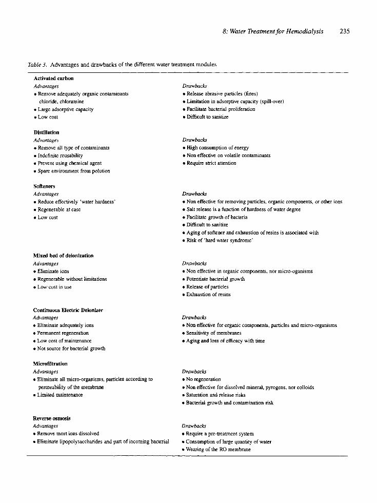
Table 3. Advantages and drawbacks of the different water treatment modules
Activated carbon
Advantages
• Remove adequately organic contaminants
chloride, chloramine
• Large adsorptive capacity
• Low cost
Drawbacks
• Release abrasive particles (fines)
• Limitation in adsorptive capacity (spill-over)
• Facilitate bacterial proliferation
• Difficult to sanitize
Distillation
Advantages
• Remove all type of contaminants
• Indefinite reusability
• Prevent using chemical agent
• Spare environment from polution
Drawbacks
• High consumption of energy
• Non effective on volatile contaminants
• Require strict attention
Softeners
Advantages
• Reduce effectively 'water hardness'
• Regenerable at ease
• Low cost
Drawbacks
• Non effective for removing particles, organic components, or other ions
• Salt release is a function of hardness of water degree
• Facilitate growth of bacteria
• Difficult to sanitize
• Aging of softener and exhaustion of resins is associated with
• Risk of 'hard water syndrome'
Mixed bed of deionlzation
Advantages
• Eliminate ions
• Regenerable without limitations
• Low cost in use
Drawbacks
• Non effective in organic components, nor micro-oganisms
• Potentiate bacterial growth
• Release of particles
• Exhaustion of resins
Continuous Electric Deionlzer Advantages
• Eliminate adequately ions • Permanent regeneration
• Low cost of maintenance
• Not source for bacterial growth
Drawbacks
• Non effective for organic components, particles and micro-organisms
• Sensitivity of membranes
• Aging and loss of efficacy with time
MicrofiUration
Advantages
• Eliminate all micro-organisms, particles according to
permeability of the membrane
• Limited maintenance
Drawbacks
• No regeneration
• Non effective for dissolved mineral, pyrogens, nor colloids
• Saturation and release risks
• Bacterial growth and contamination risk
Reverse osmosis Advantages
• Remove most ions dissolved
• Eliminate lipopolysaccharides and part of incoming bacterial
Drawbacks
• Require a pre-treatment system
• Consumption of large quantity of water
• Wearing of the RO membrane
236 Bernard J.M. Canaud and Charles M. Mion
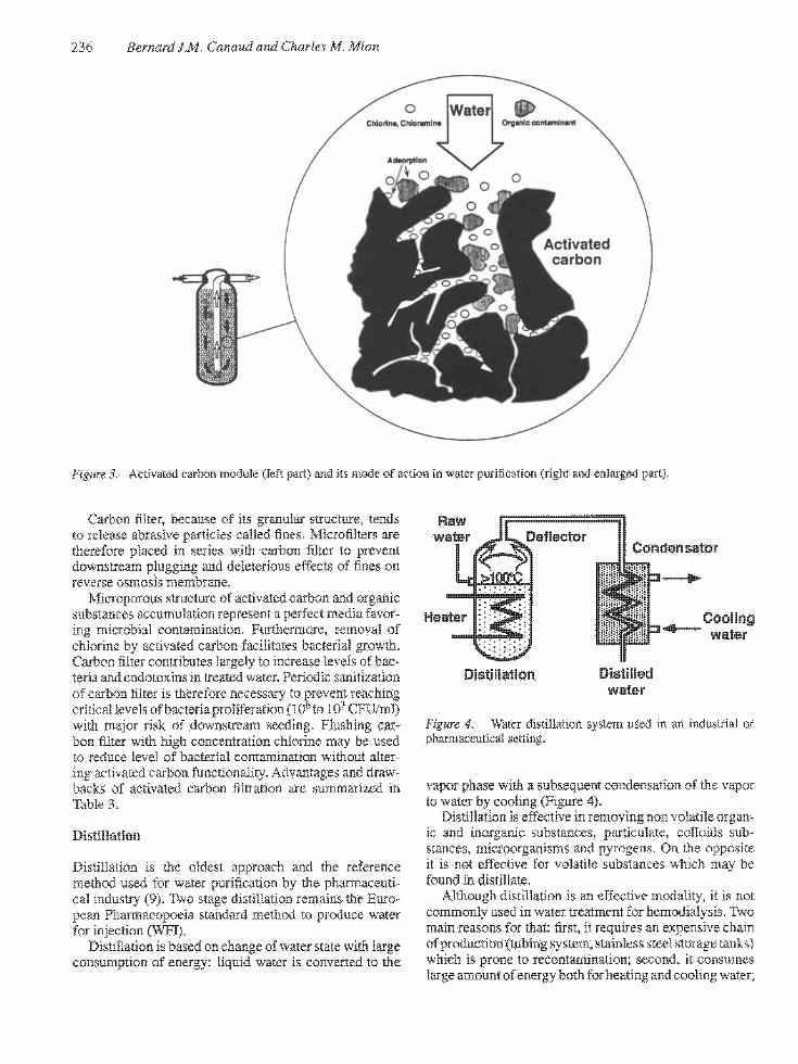
Figure 3. Activated carbon module (left part) and its mode of action in water purification (right and enlarged part).
Carbon filter, because of its granular structure, tends to release abrasive particles called fines. MIcrofilters are therefore placed in series with carbon filter to prevent downstream plugging and deleterious effects of fines on reverse osmosis membrane.
Microporous structure of activated carbon and organic substances accumulation represent a perfect media favoring microbial contamination. Furthermore, removal of chlorine by activated carbon facilitates bacterial growth. Carbon titer contributes largely to increase levels of bacteria and endotoxins in treated water. Periodic sanitization of carbon filter is therefore necessary to prevent reaching critical levels of bacteria proliferation (10^ to 10^ CFU/ml) with major risk of downstream seeding. Flushing car-boa filter with high concentration chlorine may be used to reduce level of bacterial contamination without altering activated carbon functionality. Advantages and drawbacks of activated carbon filtration are summarized in Table 3.
Distillation
Distillation is the oldest approach and the reference method used for water purification by the pharmaceutical industry (9). Two stage distillation remains the European Pharmacopoeia standard method to produce water for injection (WFI),
Distillation is based on change of water state with large consumption of energy: liquid water is converted to the
Doflector
Heater
Condensator
Cooling water
Distillation Distilled water
Figure 4. Water distillation system used in an industrial or pharmaceutical setting.
vapor phase with a subsequent condensation of the vapor to water by cooling (Figure 4).
Distillation is effective in removing non volatile organic and inorganic substances, particulate, colloids substances, microorganisms and pyrogens. On the opposite it is not effective for volatile substances which may be found in distillate.
Although distillation is an effective modality, it is not commonly used in water treatment for hemodialysis. Two main reasons for that: first, it requires an expensive chain of production (tubing system, stainless steel storage tanks) which is prone to recontamination; second, it consumes large amount of energy both for heating and cooling water;
8: Water Treatment for Hemodialysis 237
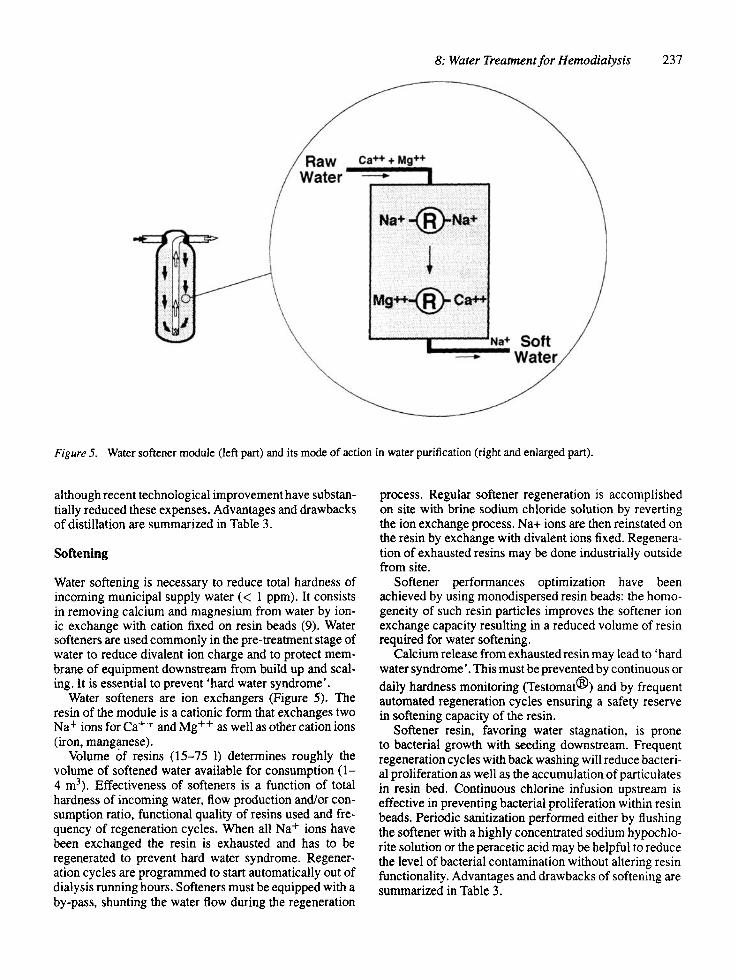
Figure 5. Water softener module (left part) and its mode of action in water purification (right and enlarged part).
although recent technological improvement have substantially reduced these expenses. Advantages and drawbacks of distillation are summarized in Table 3.
Softening
Water softening is necessary to reduce total hardness of incoming municipal supply water (< 1 ppm). It consists in removing calcium and magnesium from water by ionic exchange with cation fixed on resin beads (9). Water softeners are used commonly in the pre-treatment stage of water to reduce divalent ion charge and to protect membrane of equipment downstream from build up and scaling. It is essential to prevent 'hard water syndrome'.
Water softeners are ion exchangers (Figure 5). The resin of the module is a cationic form that exchanges two Na+ ions for Ca+"^ and Mg^^ as well as other cation ions (iron, manganese).
Volume of resins (15-75 1) determines roughly the volume of softened water available for consumption ( 1 -4 m^). Effectiveness of softeners is a function of total hardness of incoming water, flow production and/or consumption ratio, functional quality of resins used and frequency of regeneration cycles. When all Na+ ions have been exchanged the resin is exhausted and has to be regenerated to prevent hard water syndrome. Regeneration cycles are programmed to start automatically out of dialysis running hours. Softeners must be equipped with a by-pass, shunting the water flow during the regeneration
process. Regular softener regeneration is accomplished on site with brine sodium chloride solution by reverting the ion exchange process. Na-t- ions are then reinstated on the resin by exchange with divalent ions fixed. Regeneration of exhausted resins may be done industrially outside from site.
Softener performances optimization have been achieved by using monodispersed resin beads: the homogeneity of such resin particles improves the softener ion exchange capacity resulting in a reduced volume of resin required for water softening.
Calcium release from exhausted resin may lead to ' hard water syndrome'. This must be prevented by continuous or daily hardness monitoring (Testomat®) and by frequent automated regeneration cycles ensuring a safety reserve in softening capacity of the resin.
Softener resin, favoring water stagnation, is prone to bacterial growth with seeding downstream. Frequent regeneration cycles with back washing will reduce bacterial proliferation as well as the accumulation of particulates in resin bed. Continuous chlorine infusion upstream is effective in preventing bacterial proliferation within resin beads. Periodic sanitization performed either by flushing the softener with a highly concentrated sodium hypochlorite solution or the peracetic acid may be helpful to reduce the level of bacterial contamination without altering resin functionality. Advantages and drawbacks of softening are summarized in Table 3.

238 Bernard JM. Cmmd and Charles M. Mion
Conwentional Filtration
Cross-Flow Filtration
Food witer I I I f?*^ ^^ o^ o o , ^ "="0 l l | Bettntate
n Flltrato n
figure 6^ Water filtration principles: conventional filtration (perpendicular) favoring built-up and accumulatioa of contaminants at the membrane surface; cross-flow (tangential) preventing accumiiiatiori of contairdnants at tlie membrane surface.
Mlcmfilter Mlcroporous filter
mmfilter Molecylar filter
Figure 7. Illustration of the retentive capacity of microfilter compared to ultrafilter.
Filtration
Sediment filtration, as the name states, is a membrane ilter process, used to remove particulate of large size from the water supply (79-84). It prevents plugging and fouling of water treatment equipment downstream. Filtration is accomplished by particulate size exclusion while water percolates through porous medium with nominal porosity less than that particulate one (Figure 6). According to size particulate removed there are three stages of iltration: pre-filtration, micro-filtration and sub-micronic filtration: - Pre-iltration is a crude process designed to clarify raw
supply water. It eliminates the large size particulate (5-5{X) ,um) from incoming water preventing fouling of equipment downstream;
- Micro-filtration is a more refined process, removing smaller size particulate (1-5 ^m diameter) (Figure 7);
- Sub-micronic filtration is used to exclude lower size water particulate and bacteria. Membranes with pore
Depth filter Screen filter
Figure 8. Microfilter types: depth filters are made of an anange-ment of packed fiiiers knot-works in bundle; Screen filter are mads of porous inert :ind homogenous maaix.
size in the range of 0.45 ^m down to 0,1 (im are commercially available wifli surface areas large enough to reduce hydraulic resistance to a minimum and in various fittings (i.e., cartridges, fiat disks). Microbial filtration is defined as absolute with 0.22 ^m pore size membranes. It has been shown, however, that some bacterial species of minute size can cross 0.22 pm pores, and will be removed only with 0.1 ^m pore size membranes.
Except for the removal of microorganisms, filtration never reach the efficacy of reverse osmosis (RO) or ultrafiltration (UF) that work at molecular size filtration.
Filters commercially available are of two main types: depth filter (packed fibers); surface or screen filter (porous matrix) (Figure 8): - Depth filters are made of an arrangement of close
ly packed fibers knot-works in a bundle determining a variable thickness. Particulates are excluded by hazard retention (inertial impacting to media) or by adsorption into ibers.
- Screen filters are made of porous, inert and homogeneous matrix sieving incoming particulates. Retention on matrix surface is then absolute for particulates larger than medium pore diameter.
Stability of filtering media is most helpful from a clinician point of view to ensure the safety of filtering process. Filters are then best classified either in stable or unstable media according to pressure flow regimen changes. - Unstable media structure are characterized by a poros
ity size that increases with filtration pressure forbidding nominal retention rating. Such a condition facilitates the release of medium and permeation of particulates above the nominal porosity of filter. This is mainly observed with depth and fiber filters.
- Stable media means that the pore size determined during the manufacturing process remains stable whatever pressure regimen flow is used. Such filters ensure an absolute retentive capacity for particulates larger than the pore size. This is obtained mainly with screen filters.
The choice of a filter depends on its planned use: - In-depth or unstable filters used for prefiltration
remove in an inexpensive way 90-98% of suspend-

8: Water Treatment for Hemodialysis 239
ed particulates and prevent fouling and build up in equipment downstream.
- Screen filters (surface filters) on the contrary are used for post-treatment to exclude small size contaminants (resin fragments, particulate of activated charcoal, colloidal substances . . . )
Combining filters of different retentive capacity in series permits to optimize and to improve the overall effectiveness of the filtering system: serial association with down rating filtering capacity is designed to enhance final purity of water: parallel association of filters is designed to increase the production capacity while maintaining the loss of pressure charge at a low level.
Functional performances of a filter are usually defined according to their retentive capacity rating. However two major points must be underlined. First, from a terminology standpoint it is important to differentiate absolute and nominal retentive rating. Absolute retentive rating represents the diameter of the largest particulates that caimot pass through a filter in fixed conditions. Nominal retentive rating is determined by the manufacturing process and corresponds to the media pore size thai is supposed to exclude incoming particulates with a larger diameter. Second, from an effective efficacy standpoint, a filtration process is defined as a reduction percentage of incoming contaminants. Therefore, the efficacy of a filtering system will also depend upon the purity of the feeding water.
Charge-modified filter is a new and promising approach enlarging filter properties by adding a removal capacity for pyrogens. Based on the positive zeta potential of their membrane surface, such filters are able to remove negatively charged lipopolysaccharide from deionized, reverse-osmosis treated, and distilled water (85-86).
Filter fouling may be monitored by differential pressure changes occurring from pre- to post-filter in fixed functional conditions. Periodic filter changes are therefore necessary to prevent reduction of filtering capacity.
Bacterial growth is a major problem with filters. This is due to colloid and organic substances accumulation and to water stagnation, both conditions favoring bacterial proliferation.
Filters are usually not regenerable meaning that with time progressive build up of particulate matter is occurring within the membrane. When filter membrane is saturated, retention capacity may be exceeded and particulates break-through may occur. Retentive capacity is then overflowed. Filter must be replaced periodically to ensure optimal functioning and to prevent unexpected release of particulates from saturated membrane. Advantages and drawbacks of filtration are summarized in Table 3.
Ultrafiltration
Ultrafiltration (UF) is a membrane filtration process based mainly on a molecular sieving exclusion (Figure 7). It has a molecular cut off higher than reverse osmosis but lower than submicronic filtration. Ultrafilter splits incoming
water in two streams: on one side permeating the membrane is the ultrafiltrate cleared of contaminants; on the other side excluding from the membrane is the retentate a concentrate of rejected particulates (Figure 6). UF is effective in removing microorganisms, pyrogens, colloids and particulates (submicronic) with a molecular size higher than cut off point of the membrane (88-95).
Ultrafilters are made from highly permeable membrane usually synthetic (polyamide, polysulfone . . . ) arranged and packed in a plate or hollow fiber unit.
liie performances of an ultrafilter depend on the characteristics of the membrane, including hydraulic permeability, sieving molecular cut off, surface electric charges and surface area. Performances are also influenced by flow rate regimen, purity of incoming water and transmembrane pressure. Membrane adsorption, due to the chemical reactivity and zeta potential of the synthetic membranes, may also contribute significantly in removing charged particles of inflowing water. Such property extending functional capacity of ultrafilter to reactive species have been clearly demonstrated for lipopolysaccharides (87-95).
The nature of the membrane is a critical factor determining efficacy and resistance of UF to water contaminants and corrosive action of chemical disinfectant. As a membrane filtration process, ultrafiltration reduces contaminant titer of inlet water, meaning that effectiveness of UF is also a function of purity of incoming water. Optimal functioning of UF requires permanent tangential filtration flux and/or intermittent flushing preventing plugging and build up at the membrane surface. Association of ultra-filters in series enhances the overall efficacy of the UF system by reducing hazards of permeating contaminants. Programmed changes of ultrafilters is also a safe and necessary way to prevent unexpected passage of contaminants in case of ultrafilter saturation.
Ultrafilters are particularly useful and highly effective in removing pyrogens at a reasonable cost. Ultrafilter may also be used to protect RO membranes or to ensure final ultrapurity of water produced. Ultrafilters are usually placed in water posttreatment. Regeneration of industrial ultrafilter may be performed on site by chemical cleaning and back flushing. Advantages and disadvantages of UF are summarized in Table 3.
Reverse osmosis (RO)
Reverse osmosis is a membrane filtration process based on molecular sieving ( « 300 Daltons) and ionic exclusion with 90-99% rejection (9) (Figure 9). RO is the more cost competitive effective method to purify water from dissolved organic and inorganic particulates including bacteria and endotoxins (96-101).
Osmosis occurs when two solutions of different ionic concentrations are separated by a semi permeable membrane. Osmosis describes the phenomenon of solvent flowing from the less concentrated to the more concentrated side. The driving force responsible for this movement
240 Bernard J.M. Canaud and Charles M. Mion
Permeate
Osmosis Reverse Osmosis
RO Membrana
Soft water
A. Reverse osmosis principle
Rejection
Permeate
B. Reverse osmosis module
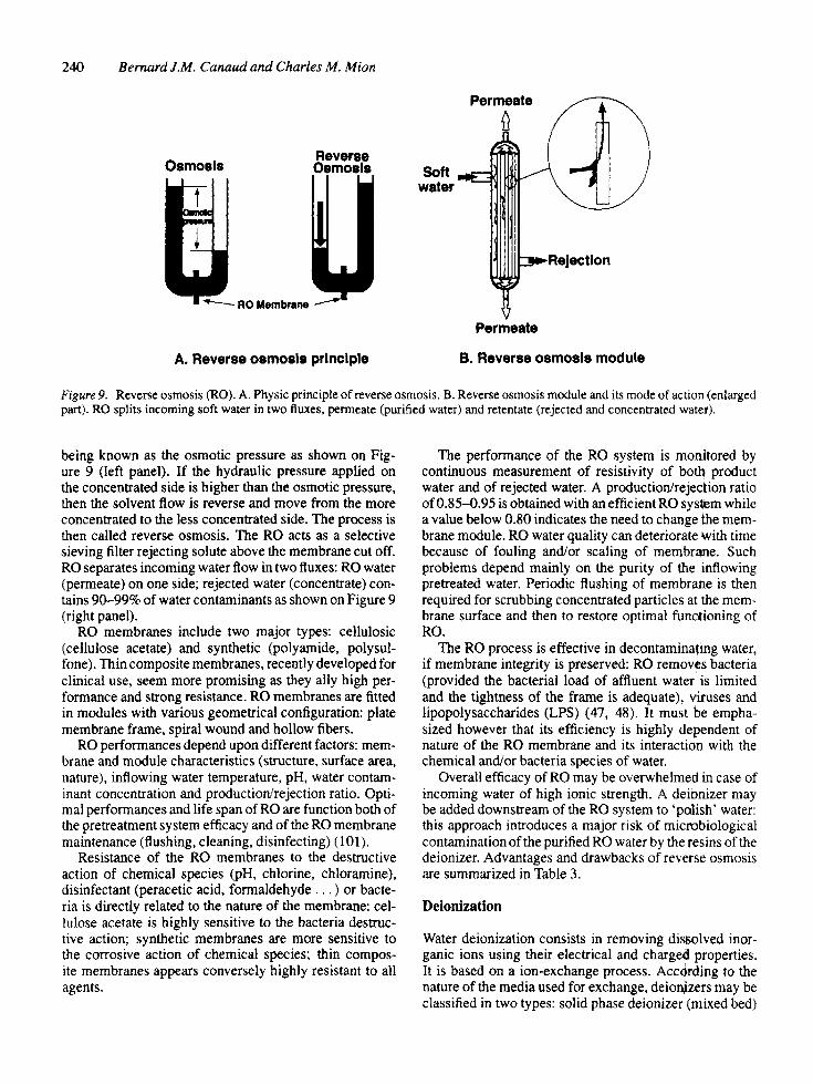
Figure 9. Reverse osmosis (RO). A. Physic principle of reverse osmosis. B. Reverse osmosis module and its mode of action (enlarged part). RO splits incoming soft water in two fluxes, permeate (purified water) and retentate (rejected and concentrated watei).
being known as the osmotic pressure as shown on Figure 9 (left panel). If the hydraulic pressure applied on the concentrated side is higher than the osmotic pressure, then the solvent flow is reverse and move from the more concentrated to the less concentrated side. The process is then called reverse osmosis. The RO acts as a selective sieving filter rejecting solute above the membrane cut off. RO separates incoming water flow in two fluxes: RO water (permeate) on one side; rejected water (concentrate) contains 90-99% of water contaminants as shown on Figure 9 (right panel).
RO membranes include two major types: cellulosic (cellulose acetate) and synthetic (polyamide, polysul-fone). Thin composite membranes, recently developed for clinical use, seem more promising as they ally high performance and strong resistance. RO membranes are fitted in modules with various geometrical configuration: plate membrane frame, spiral wound and hollow fibers.
RO performances depend upon different factors: membrane and module characteristics (structure, surface area, nature), inflowing water temperature, pH, water contaminant concentration and production/rejection ratio. Optimal performances and life span of RO are function both of the pretreatment system efficacy and of the RO membrane maintenance (flushing, cleaning, disinfecting) (101).
Resistance of the RO membranes to the destructive action of chemical species (pH, chlorine, chloramine), disinfectant (peracetic acid, formaldehyde . . . ) or bacteria is directly related to the nature of the membrane: cellulose acetate is highly sensitive to the bacteria destructive action; synthetic membranes are more sensitive to the corrosive action of chemical species; thin composite membranes appears conversely highly resistant to all agents.
The performance of the RO system is monitored by continuous measurement of resistivity of both product water and of rejected water. A production/rejection ratio of 0.85-0.95 is obtained with an efficient RO sysfiem while a value below 0.80 indicates the need to change the membrane module. RO water quality can deteriorate with time because of fouling and/or scaling of membraine. Such problems depend mainly on the purity of the inflowing pretreated water. Periodic flushing of membrane is then required for scrubbing concentrated particles at the membrane surface and then to restore optimal functioning of RO.
The RO process is effective in decontaminating water, if membrane integrity is preserved: RO removes bacteria (provided the bacterial load of affluent water is limited and the tightness of the frame is adequate), viruses and lipopolysaccharides (LPS) (47, 48). It must be emphasized however that its efficiency is highly dependent of nature of the RO membrane and its interaction with the chemical and/or bacteria species of water.
Overall efficacy of RO may be overwhelmed in case of incoming water of high ionic strength. A deionizer may be added downstream of the RO system to 'polish' water: this approach introduces a major risk of microbiological contamination of the purified RO water by the resins of the deionizer. Advantages and drawbacks of reverse osmosis are summarized in Table 3.
Deionization
Water deionization consists in removing dissolved inorganic ions using their electrical and charged properties. It is based on a ion-exchange process. According to the nature of the media used for exchange, deionjizers may be classified in two types: solid phase deionizer (mixed bed)

8: Water Treatment for Hemodialysis 241
Figure 10. Mixed bed deionizer module (left part) and its mode of action (riglit and enlarged part) as a ion resin exchanger (cationic and anionic resins).
i 6©Ci ¥V 3t©f
Pernieabic Perrai*a&fe Cation MeiTibFSM Cj" Na" Membrane Anson
Fsfmeebie s Meir.brar* i * IJJXSM I ' ' - Membrane
:' Magnetic Fieic rff^«ja''
Figure 11, CoBlinuous Electric Deionizer (CDI) module combines electrodialysis (magnetic ield, arrow) and ion exchange (resin and membrane) to produce high quality water.

242 Bernard J.M. Canaud and Charles M. Mion
(Figure 10); Continuous Electric Deionizer (Figure II) (CDI) (102-104).
Deionizer in solid phase consists in a percolation of water in resin of cationic and anionic types (mixed bed) (Figure 10). Dissolved ion particles of water are exchanged with the ions fixed on the resins, cationic resins (styrene, divinylbenzene) bearing sulfuric radical exchange hydrogens ions for cations (Na, Ca, Al . . . ) , anionic resins (styrene, divinylbenzene) bearing ammonium radical exchanges OH hydroxyl ion for anions (Cl~). The exchanged hydrogen and hydroxyl ions combine together to form water.
A deionizer consists either in a dual bed (two separate beds one each, for cationic and anionic resin in series) or mixed bed (mixture of cationic and anionic resins in the same bed). Resins consist in a mixture of styrene/divinylbenzene bed to form a polystyrene matrix. Deionizer produce water of high quality and high resistivity (> 1 megOhm/cm). Continuous in line monitoring of deionizer efficacy insured by on-line resistivity measurement with temperature compensated resistivimeter.
Efficacy of resin is correlated with its overall exchange capacity. Deionizer retentive capacity depends upon volume and resin exchange capability, ionic strength of inflowing water and consumption flow. When saturation of exchange sites is reached, the resin is exhausted. Regeneration is then necessary to prevent release of fixed cations (Ca+^, Mg++) and anions (NO3, SO4 . . . ) . Effluent water may also become acidic because of the imbalance between cations and anions exchange capacities. Regeneration of deionizer may be scheduled automatically or initiated manually when resistivity has declined to less than 1 megOhm/cm. It consists in a reverse ion exchange based on a two step procedure: first, back washing to remove particulates; second, regeneration of cationic resins with strong acid (HCl) and anionic resins with strong alcali (NaOH, bleach) to eluate fixed ions.
Deionizers are subject to fouling and bacterial proliferation which results in microbial contamination of downstream equipment.
Continuous Electric Deionizer (CDI), a more recently developed process, combines the advantages of electro-dialysis and ion exchange to produce a high quality water (Figure 11). It combines ion exchange membranes and resins to remove ions from water under the influence of an electrical field. CDI module consists in a series of thin parallel compartments separated by selective cationic and anionic membranes; in this arrangement every second compartment is filled with a mixture of cationic and anionic resins. The incoming water is separated in two fluxes: the main fraction of water is flowing through mixed resins defined as the diluting or product compartment, while a small fraction is flowing co-currently in the adjacent compartments designed as concentrate compartments. Electrical field force ions to migrate from product compartment to dilute pathway according to polarity of field and selectivity of membranes as shown in Figure 11.
The resin facilitates ion transfer by providing a lo\v resistance path for the transfer of ions. In addition as the water product become very pure, the current applied in excess splits water into hydrogen and hydroxyl ions regenerating continuously the resin.
CDI provides high quality water with resistivity up to 20 megOhm/cm. Monitoring of CDI performances may be checked by continuous measurement of resistivity on outflowing water with temperature compensated conduc-timeter.
Overall efficacy depends upon geometrical and functional characteristics of CDI (surface area exchange, number of compartment, membranes, dilute/concentrate flow ratio), incoming water composition (ionic strength, temperature, pH) and intensity of electrical field acting on the module. The continuous regeneration of the resins by electrodialysis prevents their exhaustion and does not require the use of chemical reagents.
In addition, the permanent water flux within CDI limits bacterial growth and reduces the hazards of pyrogen release downstream. Advantages and drawbacks of deion-ization are summarized in Table 3.
Ultraviolet radiation treatment
Ultraviolet (UV) radiation is a ionization process that is able to destroy all types of waterborne bacteria whatever their state, vegetative or sporulated. Microorganisms withstand considerably more to UV in water than in dry air. Bactericidal effects of UV in water is depending on the amount of energy delivered to suspended organisms and is function of the own resistance of waterborne microorganism to the UV radiations. The degree of penetration of UV (water depth layer) and the flow rate of water through the UV source are major factors of germicidal effectiveness. The variation of degree of absorption is function of mineral and organic content of water. The redaction of UV spreading through the source is observed with scaling of the lamp. The intensity of U V output of a lamp depends on the voltage, water temperature and burning hours of a lamp.
Commercial UV source are provided through mercury lamp (cold vapour of mercury) enclosed in a quartz protective sleeve allowing for higher lamp temperatures required for optimum output of UV. Germicide UV lamps have limited life time (5-10000 h) based on a continuous flow.
UV is an effective and practical alternative for disinfecting water, but it increases the lipopolysaccharide and peptidoglycane content of treated water due to process of iDacterial killing.
WATER TREATMENT SYSTEM CONCEPT
None of the individual water treatment devices described above offers the possibility of producing high purity water on a long term basis. The association of several water

8: Water Treatment for Hemodialysis 243
Table 4. Purified water according to European and US Pharmacopeia. Highly purified water (ultrapure water) according to semiconductor industry needs
Constituent
PH CWoride, mg/1
Sulfate, mg/1 Ammonia, mg/1
Calcium, mg/1
Carbon dioxide, mg/1
Heavy metals, mg/1 Total solids, mg/1
Total bacteria count, CFU/ml
Pyrogen Endotoxin, MEJmX
Purified water
(European &)
US pharmacopoeia)
5.0-7.0
<0.50
<0.10
<0.10
< 1.00
<5.00
<0.10 < 10.0
< 100 7
Ultrapure
water
5 A/n cm
5.0-7.0 <0.06
<0.08
<0.03 <0.04
<0.20
<0.01 <0.50
< 10.0
<0.25
treatment options is required to achieve a regular and constant production of high grade quality water. A water treatment system in all cases will be a chain associating several units assembled either in series or in parallel, each one having a specific function. The major contribution of water engineering should be to optimize the performance of each component to enhance the quality of final product (105-108). The assemblage of various components to make a water treatment chain results frequently in an antagonism between the chemical and microbiologic criteria of ultrapure water. For example, the improvement of ion removal by adding resins to a RO system enhances bacterial proliferation with a deleterious effect on microbiological purity.
Water treatment is a complex process that starts from water mains and ends at patient bed-side in the dialysate production. Final purity of water distributed to the hemodialysis machine will therefore integrate all imperfections in the water treatment chain.
Water treatment systems for hemodialysis include usually four sections assembled in series, which include: (1) water pre-treatment; (2) water purification system; (3) water storage (reserve) and distribution system (piping, net delivery system); (4) dialysate preparation and delivery system (dialysis machine) (Figure 1). Most dialysis machines are also a final filtration device (submicronic filter and/or ultrafilter) to ensure the microbial purity of the water feeding dialysis machine and/or the dialysate delivered to the patient's dialyzer.
The complexity of such water treatment chain explain easily the difficulties in maintaining high quality grade standards for water. It is also important to remind that the final quality of the delivered water will be negatively influenced by the worst quality segment of the water chain.
Water pre-treatment and purification systems
Chemical purification is the first stage of the water treatment system. It is one of the most important since conditioning the final purity grade of the water distributed. Water purification consists in three steps which includes: (1) pre-treatment consisting in filters, softener, carbon filter, microfilters; (2) primary treatment consisting in a reverse osmosis (one or two RO) and deionizer for 'polishing' water; (3) post-treatment consisting in ultrafiltration and submicronic filtration with or without storage tank. Various grades of water may be achieved depending directly upon complexity and cost of water purification options used. According to our present knowledge, pharmaceutical quality grade water appears as a new and generalized standard for contemporary hemodialysis. Of these waters two types are suitable for hemodialysis as presented in Table 4: (1) purified water; (2) highly purified water (ultrapure water). The chemical specifications for hemodialysis water are similar to those of water for injection. Absence of bacteria and endotoxin and a resistivity superior to 5 megOhm/cm are the main characteristic of the latter.
a. Purified water may be obtained from a relatively simple water purification system made of a pretreatment (softener) and reverse osmosis (RO) module assembled in series. Such water treatment system should represent now, the basic and common denominator for all conventional hemodialysis system.
According to the quality of the municipal water supply different options of filtration may be proposed. Basically, such water treatment purification system consists of a pre-treatment followed by a deionization by RO with straight and direct distribution system. Microfiltration may be occasionally associated as a final quality insurance. A flow diagram of such water purification treatment showing the different components is given in Figure 12.
The pretreatment consists in series of filters for large particulate removal, a cation exchange softener, an activated charcoal cartridge and a filtration down to 1.0-0.45 /xm. Permanent sanitization of resins may achieved by continuous chlorine injection in tap water.
b. Highly purified water (ultrapure water). Chemical and microbiological (bacteria viable organisms and endotoxins) limits are most stringent in this case. Quality standards are those required for water for injection with the only difference that conditions of production and instantaneous consumption preclude any microbiological control to be performed (Table 4).
Highly purified water may be produced using different treatment options. Schematically, three different types of water treatment chains are presented that seem to offer the best quality insurance consisting in:
1. The first type presented in Figure 13, consists in a pretreatment system followed by two stage deioniza-

244 Bernard J.M. Canaud and Charles M. Mion
MIcroflttM'
MicroflKar
Raw Water Distribution
Loop
Figure 12. Basic water treatment chain for hemodialysis consists in a pre-treatment (microfiltration, activated carbon, softener) completed by a RO module and a direct production of treated water to the dialysis unit through a recirculating loop.
Distribution Loop
Miaofllter Microfiiter MIcrofilter
Reverss Osmosis
Raw Water
t i l iJf
,>1l!t Pump Submicronic
0.1 p Filter +
Figure 13. Water treatment chain designed to produce highly purified water. It consists in a pre-treatment followed by a two stages RO treatment. Storage tank is used in this case to prevent any imbalance due to peak flow consomption. Microbiologit purity of water is insured by a permanent recirculation through two serial positively charged submicronic (0.1 /jm) filter.
tion by RO completed by a final filtration using a 0.1 /xm pore size filter membrane. The treated water is distributed to the dialysis machines through a recirculation loop. The pretreatment uses a series of filters for large particulate removal (5-1 /xm), a dual softener and activated carbon filter followed by a filtration down to 0.45 /xm. The water treatment consists in two RO units placed in series. An intermediary storage tank may be useful to prevent any RO dysfunction by fluid imbalancing. Rejection flow is discarded on the first RO module while it is recirculated and mixed with softened water on the second RO module. RO modules use cellulose acetate or composite membrane.
2. The second type of chain shown in Figure 14, consists in a pretreatment system followed by primary deion-ization by RO, completed by polishing deionization by CDI and a final ultrafiltration or mictofiltration (0.22 or 0.1 ^m positively charged). Pretrtatment is the same as previously described. RO unit; uses synthetic or composite membrane. RO is operated at 50-60% rejection to reduce the rate of fouling. The CDI unit is a single stage, 30 parallel plate cell designed to produce a nominal product flow of 20 Ifmin. CDI is operated at 80-85% recovery. The ultrkfilter unit is made of a spiral synthetic membrane or a hollow fiber used at a low rejection rate and/or with periodi-

8: Water Treatment for Hemodialysis 245
Distribution Loop
MIcrotilter
Raw Water
Mlaodlter
Submlcronic Oltar -r
Drain
Figure 14. Water treatment chain designed to produce highly purified water. It consists in a pre-treatment completed by RO treatment then polished by Continuous Electric Deionizing (CDI). Storage tank is used in this case to prevent any imbalance due to peak flow consumption. Microbiologic purity of water is insured by a permanent recirculation through serial positively charged submicronic (0.1 /im) filter.
cal flushing of the membrane. The RO, CDI and UF should be sanitized at regular intervals at least monthly and preferably weekly. Chemical disinfection may be performed, according to the manufacturer recommendations, using appropriate concentrations of formaldehyde or peracetic acid or chlorine. Simplification of sanitization has been made possible through the use of a single and common chemical agent both for RO, CDI and ultrafilters.
3. The third type of chain shown in Figure 15 consists in a pretreatment system followed by a primary deion-ization (mixed bed) then enhancing microbiological quality by final filtration (ultrafiltration or preferably microfiltration); RO can be used for that purpose, but the rejection flow should be recirculated and mixed with the afferent water feeding the deionizer. Deioniz-er consists in a mixed anionic cationic resin exchange unit. RO unit uses a synthetic or a composite membrane. Ultrafiltration unit or submicronic filtration insure the final purity of water produced to the dialysis unit by eliminating endotoxins and bacteria.
Water storage
A water tank is not always required in a water distribution circuit: whenever possible, it is preferable to avoid it, as water stagnation in a reservoir favors bacterial growth. A tank can be avoided when the production capacity of the water treatment system exceeds at all times the consumption needs of the dialysis units (Figure 12). A reservoir will be necessary when water consumption in the dialysis unit varies during the day with peak consumption
flow exceeding the instantaneous production capacity of the water treatment system; it is also requisite to keep a water safety reserve in a large dialysis unit or to prevent flow and hydrostatic pressure imbalances between the various components of the water treatment system. In practice, water storage can be dispensed with in small dialysis units (e.g., self dialysis or limited care facilities) or in home hemodialysis, while it becomes mandatory in large dialysis facilities. When water storage is required, a reservoir should be designed specifically and integrated into the water distribution system (Figures 13-15). Closed stainless steel storage tank offers the best choice for this purpose. Vessel design is important to prevent water stagnation. The interior of the reservoir is concave at both ends. The internal surface is polished to discourage bacterial adhesion. Water arrives at the upper entry point of the reservoir, impinges into a concave badffle which directs the water stream along the inner surface of the vessel, thus assuring permanent lavage of the wall. Water is continually pumped into the circuit from the bottom of the reservoir either forward in the distribution loop for dialysis use or backward in the water treatment system when dialysis unit is not rurming.
Reservoir is maintained under pressure of water supply circuit when placed before RO. Event of the reservoir are protected from bacterial contamination by micro-filters (0.1 /xm). Level probes (max and min) are also necessary to check filling state and action automatically filling/emptying cycles.

246 Bernard J.M. Canaud and Charles M. Mion
Microflttar
MIcrofltter Mlcfotitter Mlcfotllter
Raw Water
Reverse " ^ Osmosis Delonlzer
mixed bed
^ Drain
Distribution i^ Loop
I UF P Submicronic
Filter*
Figure 15. Water treatment chain to produce highly purified water. It consists in a pre-treatment completed by RO treatment then polished by mixed bed deionizing. Treated water is directly flowed to the dialysis unit without storage then recirculated. Microbiologic purity of water is insured by a permanent recirculation through serial submicronic (0.1 /xm) filter and/or ultrafilter.
Water and dialysate distribution system
The hydraulic circuit starts from the water mains, supplying the dialysis unit and leads into the dialysate compartment of the dialyzer. It forms a complex path that comprises three major segments:
- The first segment includes the pretreatment and treatment water systems. As indicated above, it is the most complex part of the hydrostatic circuit and it will not be discussed further here.
- The second segment, that should be linear, may include a reservoir and ends into the various ports of utilisation in the dialysis center; it includes the tubes connecting the hemodialysis machines to the main piping.
- The third segment consists of as many hydraulic circuits as they are HD machines. The complexity of the hydraulic pathway inside the machines creates numerous niches facilitating bacterial adhesion and proliferation. To prevent bacterial contamination of dialysis water and of dialysate, the hydraulic circuit should be carefully designed by the manufacturer.
The design of the hydraulic installation is a critical point that will have a major impact on the degree of bacterial contamination of water and thus of dialysate. Since the extra cost in this area is modest the greatest effort should be made to obtain the best plumbing configuration. Without entering into details of such technical points, four principal criteria that must be adhered to should be underscored.
First, hydraulic circuit requires a design that insures linear circulation of the water. Elimination of any by-pass creating stagnation zones. If valves are required on the water distribution piping, they should be placed on lateral
arms whose length does not exceed the diameter of the principal circuit.
Second, to prevent bacterial adhesion to the ianer surface of the piping, high water velocity and shear rate should be obtained by selecting a pipe with the smallest irmer diameter compatible with the required flbw. The material chosen should have a smooth and polished inner surface and joints that disrupt piping continuity should be avoided. Stainless steel, that can be welded without crack formation at the inner surface, thus preventing the formation of bacterial niches, is the ideal material. Its high cost, however, has been an impediment to its routine use. High grade PVC is more commonly used, because of its lower cost: high bacterial quality can be obtained provided the piping installation is carefully designed and regularly disinfected.
Third, continuous water circulation is a basic necessity to prevent water stagnation and bacterial growth. If possible, storage reservoir should be avoided. If this impossible, reservoir with a recirculating loop Including a filtration system must be operated 24 h a day.
Fourth, dead space and lateral arms (manyfolds) must be avoided or reduced to a minimum. Tubing connecting the distribution loop to the dialysis machine should be as short as possible as shown in Figure 16.
Final filtration
When a storage tank is used, water flow in the recirculation loop is provided by dual centrifugal punlps which maintain the hydrostatic pressure at the level required for proper functioning of the various systemsi fed with ultrapure water. A cold sterilisation system, made of an ultrafilter or preferably a submicronic filters with positive zeta potential at the filter membrane surface (0.1 ^m

Water Treatment From System To
Recirculating Loop
iJiilriilnJ .
:
1
•
1
2 3
HD machines
Dialysis Unit
Figure 16. Tubing connecting the water distribution loop to the dialysis machine must be as short as possible to reduce dead space and water stagnation. This is illustrated by the 3 mode of connection: 1. Conventional tubing. 2. Short tubing connecting system. 3. Total suppression of tubing dead space with a specific connecting device.
pore size, Posidyne®, Pall, NY, USA) is placed after the pumps, at the inlet of the recirculation loop. This system should eliminate all the bacteria that may have grown in the water stagnant into the reservoir. ITie recirculation loop returns to the reservoir, the water not utilized in the dialysis center. Optimal fiinctioning of such a distribution closed loop system is based on four major rules: first, permanent water flux and bacterial absolute filtration to lower bacterial growth in the reservoir and to eliminate bacteria and endotoxins from the water running into the loop; second, high flow rate to impede the bacterial colonization of the pipes; third, careful cleaning and disinfection of the hydraulic circuit at regular intervals to prevent biofilm formation and bacterial contamination; fourth, prevention of back contamination through lateral arms by regular disinfection and physical disconnection of the HD machines when they are not in use.
WATER TREATMENT SYSTEM MAINTENANCE AND HYGIENE OF DIALYSIS
As discussed previously, both proper design of the hydraulic circuit and adequate hygienic measures are the two key conditions to obtain high quality water for dialysis. The careful maintenance of a water treatment system is essential to insure the continuous production and distribution of ultrapure water. Thus maintenance relies on three complementary measures: disinfection; filters and/or resins changes; biofilm destruction.
8: Water Treatment for Hemodialysis 247
Disinfection
Disinfection is necessary to reduce the degree of bacterial contamination in a water treatment system production (109-112). It must be adapted to die segment of die water treatment chain considered and to the level of contamination (Figure 17).
Bacteria lodging inside in depth filters, softeners resins and activated charcoal are very difficult to remove. All these material, easily penetrated by water-borne bacteria, offer excellent niches facilitating bacterial growth. To reduce microbial multiplication in this critical sector of the water treatment chain, several measures are required: (1) permanent addition of bleach to raw water to enhance free chlorine level to reach 0.3 mg/1 within filters and softener resins; (2) pulse disinfection of activated charcoal by high bleach flushing once a week; (3) suppression of activated charcoal if possible and free chlorine neutralization by downstream infusion of thiosulfate.
Periodic disinfection of RO, CDI and ultrafilters may be achieved by using a chemical disinfectant. The choice of disinfectant must be done in accordance with material specifications and manufacturer recommendations to prevent any damaging effect. Periodicity, concentration and time exposure to the agent are dependent upon the nature of the disinfected material, the degree of contamination and the kinetics of recontamination.
Filter and resin changes
Filters, softeners, activated charcoal and deionizers represent an ideal support for microbial growth. On the one hand, porosity of these material facilitate adhesion and penetration by circulating water-borne bacteria. On the other hand, presence of organic substances enhance bacteria growth by providing nutrient media. When bacteria have colonized such material they are very difficult to dislodge by a back-washing or to kill by disinfectants and/or chemical germicides. Moreover, heavily contaminated filters overpassing their retentive capacity are subject to release with risk of downstream contamination of equipment. Disinfection permits to reduce bacterial contamination of a water treatment system in a limited and/or an acceptable range. However disinfection alone cannot insure sterility for a prolonged period of time when filters or resins are contaminated. Therefore, periodical changes of filters and resins, combined with frequent disinfection cycles, is the only way to optimize microbiological results and to insure on the long term the production of ultrapure water (113).
BioiUm synthesis and destruction
Bacterial adhesion to inert surface material occurs inevitably in all water distribution piping network (114). Such adhesion is facilitated by reduced water flow and low shear rates at the water-tubing interface by areas of
248 Bernard J.M. Canaudand Charles M. Mion
Raw Water Dlslrtbution
Loop
Chlorine cantlmmtialf Pemcetlc add
or FormaWehyele Perocetic acid or Formaldehyde
or Steam sterilization porlodlcallf
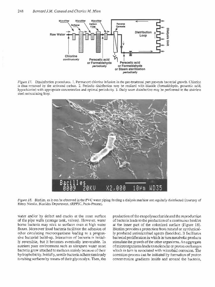
Figure 17, Dinsiafection procedures. 1. Permanent clilomie infusion ia the pre-treatment part prevents bacterial growth, Chiorine is then removed by the activated csirbon. 2. Periodic disinfection r?)ay be realized with biocide (formaldehyde, pcracctic add, hypochlorite) with appropriate concentration and optimal periodicity. 3. Daily seam disinfection may be performed m die stainless steel recircttlating loop.
Figure 18. Bioilm, as it can be obser 'ed in the PVC water piping feeding a dialysis machine not regularly disinfected (courtesy of Remy Nicolle, Biocides Etepartment, SEITIC. Pajis-France). '
water and/or by defect and cracks at the inner surface of the pipe walls (storage tank, vakes). However, water borne bacteria may stick to surfaces even at high water fluxes. Moreover fixed bacteria facilitate the adhesion of other circulatiEg microorganisms leading to a progressive bacterial build-up. Interaction of bacteria is initially reversible, hut it becomes eventually irreversible. In nutrient poor environment such as ultrapure water most bacteria grow attached to surfaces mainly because of their hydrophobicity. Initially, sessile bacteria adhere randomly to tubing surfaces by means of flieir glycocalyx. Tlien, the
production of the exopoly saccharide and the reproduction of bacteria leads to the production of a continuous Moilm at the irmer part of the colonized surface (Figure 18). Bioilm provides a protection from natural or synthetically produced antimicrobial agents (biocides). It facilitates bacterial proliferation in which in turn metabolic products stimulate the growth of the other organisms. An aggregate of microorganisms leads to molecular or proton exchanges which in turn is associated with microbial corrosion. The corrosion process can be initiated by formation of proton concentration gradients inside and around the bacteria,

8: Water Treatment for Hemodialysis 249
Figure 19. Biofllm striping efffxt of a pcracetic acid solution (Dialox®"', CFPO, Paris-France). PVC tubing appears clean and germ4re.e. Only silicium deposits can be obsen-ed at the tubing surface (courtesy of R6iTiy Nicolle, Biocides Department, SEFPIC, Paiis-France).
which generate electrochemical forces within the bioilm. High grade stainless steel is the only material resistant to this corrosion phenomenon.
Most plastics contains synthetic polymers which are resistant to microbial degradation with the exception for low molecular weight polyethylene and polyesters. Plastics may also contains plasticizers, pigments, stabilizers, lubricaats that may serre as nutrients for bacteria and fungi. Even though the plastic is not degraded, its resistance may be altered. Bacterial growth may cause plastic pipes to become brittle and crack. Fungi may grow inside plastic material and on thefr surface modifying their aspect.
Prevention and destruction of bioilm is therefore an essential aim in the hygiene of the water distribution systems. Few detergent agents can induce the hydrolysis of the exopolysaccharide shield. Bleach, sodium hydroxide and peroxyacetic acid preparation which demonstrate detergent properties, should be periodically employed to strip the bidfilm away from the inner surface of the pipe wall and disinfect adequately the water distribution pipes (Figure 19).
WATEM TEEATMENT QUALITY CONTROL
Chemical purity
The methods used for monitoring the effectiveness of each water treatment options have been discussed in paragraphs
above. Basic requirements for an adequate control of the chemical purity of the water produced are summarized in this section (115).
The effectiveness of the softener may be monitored either periodically (daily or weekly) by measuring the hardness of the effluent water using suitable titration kits (resolution of less < 1 mg/l) or permanently by a sensitive
automated probe (Testomat®) equipped with appropriate alarms which will inform the nursing personnel of the dialysis center if tie hard water is not adequately softened.
The filters (sediment filters, ultrafilter) capability must be monitored to prevent plugging and sloughing risks. It is therefore important to monitor the pressure drop across the filters by suitable pressure gauges; the ilters will be discarded and replaced when the pressure gradient across the filler reaches the safety limits specified by the manufacturer.
Chlorine removal by activated charcoal is important to prevent RO membrane damage. The effectiveness of activated charcoal must be monitored by measuring chlorine concentration in the effluent. This control can be performed periodically with appropriate dosage kits or permanently monitored by an appropriate probe under automated control.
The effectiveness of a desionizer (conventional mixed bed or CDI) and of a RO system can be monitored permanently by measuring the resistivity of the effluent water produced using an adequate resistivimeter. With RO the
250 Bernard J.M. Canaud and Charles M. Mion
Endotoxin, LAL-detectable, pg^ml
350-
300-
250-
200.
150.
100-
50-Q t
Raw water
sor wati
CtMicoal
1 M r w atvO.«
Siorad T UcraNlaradTf waMr 1 wataraiOf* |
Id P
R.O. Storab watar watar
11^
IcacuMng loop
Malyaala
Connacting Wlrapur i tubing dialyaala
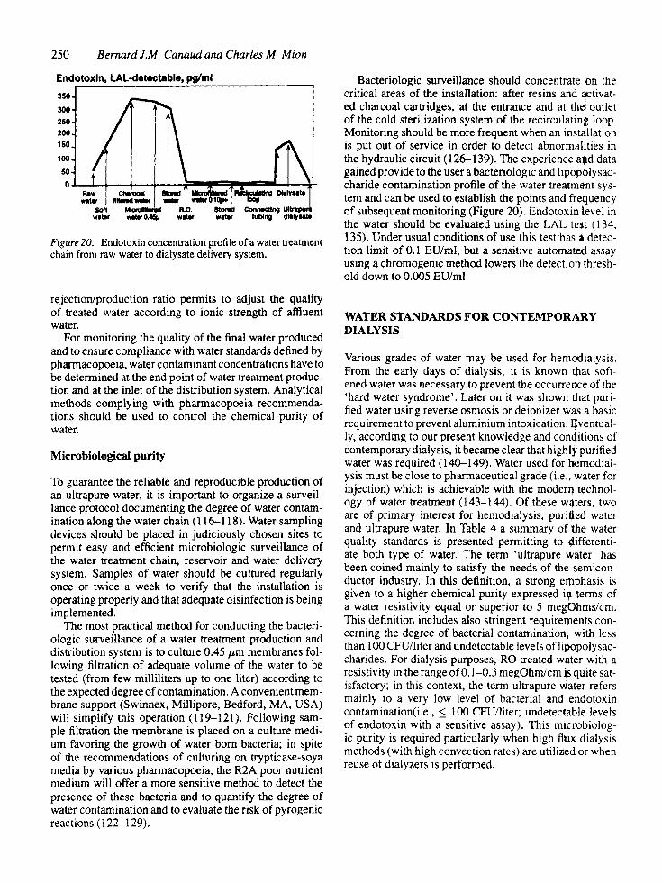
Figure 20. Endotoxin concentration profi le of a water treatment chain from raw water to dialysate delivery system.
rejection/production ratio permits to adjust the quality of treated water according to ionic strength of affluent water.
For monitoring the quality of the final water produced and to ensure compliance with water standards defined by pharmacopoeia, water contaminant concentrations have to be determined at the end point of water treatment production and at the inlet of the distribution system. Analytical methods complying with pharmacopoeia recommendations should be used to control the chemical purity of water.
Microbiological purity
To guarantee the reliable and reproducible production of an ultrapure water, it is important to organize a surveillance protocol documenting die degree of water contamination along the water chain (116-118). Water sampling devices should be placed in judiciously chosen sites to permit easy and efficient microbiologic surveillance of the water treatment chain, reservoir and water delivery system. Samples of water should be cultured regularly once or twice a week to verify that the installation is operating properly and that adequate disinfection is being implemented.
The most practical method for conducting the bacteri-ologic surveillance of a water treatment production and distribution system is to culture 0.45 /xm membranes following filtration of adequate volume of the water to be tested (from few milliliters up to one liter) according to the expected degree of contamination. A convenient membrane support (Swinnex, Millipore, Bedford, MA, USA) will simplify this operation (119-121). Following sample filtration the membrane is placed on a culture medium favoring the growth of water born bacteria; in spite of the recommendations of culturing on Q-ypticase-soya media by various pharmacopoeia, the R2A poor nutrient medium will offer a more sensitive method to detect the presence of these bacteria and to quantify the degree of water contamination and to evaluate the risk of pyrogenic reactions (122-129).
Bacteriologic surveillance should concentrate on the critical areas of the installation: after resins and activated charcoal cartridges, at the entrance and at the outlet of the cold sterilization system of the recirculating loop. Monitoring should be more frequent when an installation is put out of service in order to detect abnormalities in the hydraulic circuit (126-139). The experience and data gained provide to the user a bacteriologic and lipopolysac-charide contamination profile of the water treatment system and can be used to establish the points and frequency of subsequent monitoring (Figure 20). Endotoxin level in the water should be evaluated using the LAL test (134, 135). Under usual conditions of use this test has a detection limit of 0.1 EU/ml, but a sensitive automated assay using a chromogenic method lowers the detection threshold down to 0,005 EU/ml.
WATER STANDARDS FOR CONTEMPORARY DIALYSIS
Various grades of water may be used for hemodialysis. From the early days of dialysis, it is known that softened water was necessary to prevent the occurrence of the 'hard water syndrome'. Later on it was shown that purified water using reverse osmosis or deionizer was a basic requirement to prevent aluminium intoxication. Eventually, according to our present knowledge and conditions of contemporary dialysis, it became clear that highly purified water was required (140-149). Water used for hemodialysis must be close to pharmaceutical grade (i.e., water for injection) which is achievable with the moderri technology of water treatment (143-144). Of these waters, two are of primary interest for hemodialysis, purified water and ultrapure water. In Table 4 a summary of the water quality standards is presented permitting to differentiate both type of water. The term 'ultrapure water' has been coined mainly to satisfy the needs of the semiconductor industry. In this definition, a strong emphasis is given to a higher chemical purity expressed ia terms of a water resistivity equal or superior to 5 megOhms/cm. This definition includes also stringent requirements concerning the degree of bacterial contamination, with less than 100 CFU/liter and undetectable levels of lipopolysac-charides. For dialysis purposes, RO treated water with a resistivity in the range of 0.1-0.3 megOhm/cm is quite satisfactory; in this context, the term ultrapure water refers mainly to a very low level of bacterial and endotoxin contamination(i.e., < 100 CFU/liter; undetectable levels of endotoxin with a sensitive assay). This microbiologic purity is required particularly when high flmx dialysis methods (with high convection rates) are utilized or when reuse of dialyzers is performed.
8: Water Treatment for Hemodialysis 251
CONCLUSIONS
Contemporary dialysis has created new needs for the water purification system. Treated water utilized in hemodialysis machine must satisfy more stringent constraints of purity both for chemical and microbiological.
Pharmaceutical grade or highly purified water, so called ultra-pure water, has become a new standard for the dialysis of the 90s. Several reasons support this need. Limitations of conventional dialysis as a long term treatment modality (> 10 years) has become largely evident over the last decade. A growing number of patients are suffering from the bone and joint long term dialysis syndrome induced by ^2-microglobulin amyloidosis.
Hemoincompatibility of the hemodialysis system has been regularly raised as a potential causal factor. Release of pro-inflammatory mediators from protein and cell system activation occuring through the blood-membrane interaction is enhanced by water contaminant and/or by-products. Role of bacteria fragments such as lipopolysacharides or muramyl-dipeptides appears particularly important in this context. Highly purified water, used to produce ultra-pure dialysate, must be considered as a major component of the hemodialysis hemocompati-bility complex.
Technical conditions of contemporary dialysis enhance the risk and the hazards of using contaminated dialysate. Bicarbonate buffer largely used in dialysis units facilitate bacterial growth with a subsequent production of endotoxin in dialysate. Highly permeable membrane increasingly used for their solute removal performances tend to facilitate penetration of endotoxin fragments into the blood stream. Ultrafiltration controller used for highly permeable dialyzers enhance the backfiltration and/or the backdiffusion phenomenon that may potentiate the microbiological hazards of contaminated dialysate.
Newly developed methods increasing the convective part in the dialysis efficacy, based on the on-line production of substitution fluid such as hemofiltration (HF) or hemodiafiltration (HDF), are more widely applied. High microbiologic water purity is an essential pre-requisite to insure the safety of these alternative methods to standard hemodialysis.
Reconditioning dialyzer process using treated water require also ultra-pure water. The use of such a high purity water is mandatory to prevent the introduction of pyro-genic substances within the blood compartment of the dialyzer.
The routine use of ultrapure water in the dialysis center is one of the major attainments of the 90s. Progress in water treatment technology and improved understanding of water borne ecology permits the safe and easy production of pharmaceutical grade water (i.e., water for injection according to pharmacopeia specifications). Using a bacteria free water, cleared from lipopolysaccha-rides, is the simplest approach to minimize the patient-hemodialysis interactions (i.e., blood monocytes activa
tion and cytokines production). Time will tell wether this purified environment provided by ultrapure dialysate delays (or prevents) the occurrence of late dialysis complications such as /?2M-amyloidosis. Ultrapure water was developed mainly to satisfy the stringent specification of the semiconductor industry. Due to increased awareness of the biological hazards of extra-corporeal circulation and blood transmembrane contact with a polluted dialysis fluid is a strong stimulus to provide hemodialysis patient with a sterile endotoxin free dialysate (140).
REFERENCES
1. Man NK, Funck-Brentano JL: Dialyzers and water treatment, in Therapy of Renal Diseases and Related Disorders, edited by Suki WN, Massry SG, Boston, Martinus N'ijhoff Publishers, 1984, p 545
2. Easterling RE: Mechanical aspects of dialysis including dialysate delivery systems and water for dialysate. in Clinical Dialysis, edited by Nissenson AR, Fine RN, Gentile DE, Philadelphia, Hanley & Belfus, Inc, 1984, p53
3. Luehmann DA: Water purification for hemodialysis. Med Instrum 20; 74, 1986
4. Comty CM, Shapiro FL: Pretreatment and preparation of city water for hemodialysis, in Replacement of Renal Function by Dialysis, edited by Drukker W, Parsons FM, Maher JF, Martinus Nijhoff Publishers, 1986, p 155
5. Laskey DA, Schell D: Addressing new water treatment standards and technologies. Contemp Dial Nephrol 10: 35, 1989
6. Vallot D: Purified water fror hemodialysis: present needs (Part 1) (in French). Techniques Hospitalieres 529: 65, 1989
7. Vallot D: Purified water fror hemodialysis: present needs (Part 2) (in French). Techniques Hospitalieres 529; 45, 1989
8. Man NK, Ciancioni CH, Guyomard S, Blais D, Delons S, Funck-Brentano JL: Risks and hazards of contaminated dialysate associated with high flux membranes, in Prevention in Nephrology, edited by Buccianti G, Masson, Italia, 1987, p 227
9. Keshaviah P, Luehmann D: The importance of water treatment in haemodialysis and haemofiltration. Proc Eur Dial Transplant Assoc Eur Renal Assoc 21: 111, 1984
10. Meeks JN: Water refining considerations for high flux dialysis (Part I). Contemp Dial Nephrol 10: 27, 1989
11. Meeks JN; Water refining considerations for high flux dialysis (Part 2). Contemp Dial Nephrol 10: 38, 1989
12. Baurmeister U, Travers M, Vienken J, Harding G, Millon C, Klein E, Pass T, Wright R: Dialysate contamination and back filtradon may limit the use of high-flux dialysis membranes. Trans Am Soc Artif Intern Organs 35: 519, 1989
13. Leypoldt JK, Schmidt B, Gurland HJ: Measurement of backfiltration rates during hemodialysis with highly permeable membranes. Blood Purif9: 74, 1991
14. Leypoldt JK, Schmidt B, Gurland HJ: Net ultrafiltration may not eliminate backfiltration during hemodialysis

252 Bernard J.M. Canaud and Charles M. Mion
withhighly permeable membranes. j4rri/0rganj 15: 164, 32. 1991
15. Vanholder R, Van Haecke E, Ringoir S: Endotoxin transfer through dialysis membranes: small-versus large-pore 33. membranes. Nephrol Dial Transplant 7: 333, 1992
16. Petersen J, Hyver SW, Cajias J: Backfiltration during dialysis: a critical assessment. &/«i>tr'/(3/5: 13, 1992
17. Klinkmann H, Ebbighausen H, Uhlenbusch I, Vienkcn J: High-flux dialysis, dialysate quality and backtransport. in Contrib Nephrol. Vol 103, Basel, Karger, 1993, p 89
18. Favero MS, Petersen NJ, Carson LA, Bond WW, Hind- 34. man SH: Gram-negative water bacteria in hemodialysis systems. J Am Soc Microbiol (HLS) 12: 321, 1975
19. Petersen NJ, Boyer KM, Carson LA, Favero MS; Pyro- 35. genie reactions from inadequate disinfection of a dialysis fluid distribution system. Dial Transplant 7: 52, 1978
20. Watzke H, Mayer G, Schwartz HP, Stanek G, Rotter M, Hirschl AM, Graf H: Bacterial contamination of dialysate 36. in dialysis-associated endotoxaemia. J Hasp Infect 13: 109, 1989
21. Goetz A, Yu VL, Hanchett JE, Rihs JD: Pseudomonas Stutzeri bacteriemia associated with hemodialysis. Arch 37. Intern Med \^y. 1909, 1983
22. Dinarello CA, Krueger JM: Induction of interleukin 1 by 38. synthetic and naturally occuring muramyl peptides. Fed Proc 45: 2545, 1986
23. Bingel M, Lonnemann G, Shaldon S, Koch KM, Dinarel- 39. lo CA: Human Interleukin-1 production during hemodialysis. A^ep/iron 43: 161, 1986
24. Mion CM, Canaud B; 'On-site' preparation of sterile 40. apyrogenic electrolyte solutions for hemofiltration and hemodiafiltration. in Short Dialysis, edited by Cambi V, Boston, Martinus Nijhoff Publishers, 1987, p 261
25. Canaud B, Flavier JL, Argiles A, Stec F, Nguyen QV, Bouloux Ch, Garred LI, Mion C: Hemodiafiltration with 41. on-line production of substituion fluid: long-term safety and quantitative assessment of efficacy. Contrib Nephrol 108: 12, 1994 42.
26. Petersen NJ, Carson LA, Favero MS: Bacterial endotoxin in new and reused hemodialyzers: a potential cause of endotoxinemia. Trans Am Soc Artif Intern Organs 28: 43. 155, 1981
27. Bolan G, Reingold AL, Carson LA, Silcox VS, Woodley 44, CL, Hayes PS, Hightower AW, McFarland L, Brown JW, Petersen NJ, Favero MS, Good RC, Broome CV: Infections with Mycobacterium Chelonei in patients receiving 45. dialysis and using processed hemodialyzers. J Infect Dis 152: 1013, 1985
28. Lowry PW, Beck-Sague CM, Bland LA, Aguero SM, Arduino MJ, Minuth AN, Murray RA, Swenson JM, Jarvis WR: Mycobacterium chelonae infection among 46. patients receiving high-flux dialysis in a hemodialysis clinic in California. 7/n/ecr Dij 161: 85, 1990
29. Alter MJ, Favero MS, Miller JK, Moyer LA, Bland LA: National surveillance of dialysis-associated diseases in 47. the United States, 1987. Trans Am Soc Artif Intern Organs 35: 820, 1989
30. Vanholder R, Vanhaecke E, Ringoir S: Waterbome 48. Pseudomonas septicemia. Trans Am Soc Artif Intern Organs 36: M215, 1990
31. Alter MJ, Favero MS, Moyer LA, Bland LA: National 49. surveillance of dialysis-associated diseases in the United States. Trans Am Soc Artif Intern Organs 37: 97, 1991
Held PJ, Levin NW, Bovbjerg RR, Pauly MV, Diamond LH: Mortality and duration of hemodialysis treatment. JAMA 265: %1\, 1991 Gordon SM, Oettinger CW, Bland LA, Oliver JC, Arduino MJ, Aguero SM, McAllister SK, Favero MS, Jarvis WR: Pyrogenic reactions in patients receiving conventional, high-efficiency, or high-flux heniodialy-sis treatments with bicarbonate dialysate containing high concentrations of bacteria and endotoxin. J Am Soc Nephron: 1436, 1992 Tokars JI, Alter MJ, Favero MS, Moyer LA, Blind LA: National surveillance of hemodialysis associated diseases in the United Sutes. ASAIO 7 39: 71, 1993 Bland L, Alter M, Favero M, Carson L, Cusick L: Hemodialyzer reuse: practices in the united states and implication for infection control. Trans Am &)c Artif Intern Organs 31: 556, 1985 Canaud B, Peyronnet P, Armynot AM, Nguyen QV, Attis-so M, Mion C: Ultrapure water: A need for future dialysis. Proc Eur Dial Transplant Assoc-Eur Renal Assoc 23 (Abstract): 113, 1986 McNulty J: The proper sizing of ultrapure water delivery systems. Contemp Dial Nephrol 12: 30, 1991 McNulty J: Improving your water-treatment system? Here is how to get the latest technology and cut costs. Contemp Dial Nephrol 13: 18, 1992 Curtis JR, Wing AJ, Coleman JC: Bacillus cereus bac-teraemia: a complication of intermittent haemodialysis. Lancet 1: 136, 1967 Alfrey AC, Mishell JM, Burks J, Contiguglia SR, Rudolph H, Lewin E, Holmes JH: Syndrom* of dyspraxia and multifocal seizures associated with chronic hemodialysis. Trans Am Soc Artif Intern Organs 18: 257, 1972 Ward MK, Pieridcs AM, Fawcett P, Shaw DA, Perry RH, Tomlinson BE, Kerr DNS: Dialysis encephalopathy syndrome. Proc Eur Dial Transplant Assoc 13: 348, 1976 Flendring JA, Kruis H, Das HA: Aluminium intoxication: the cause of dialysis dementia? Proc Eur Dial Transplant Assoc 13: 355, 1976 Alfirey AC, Legendre GR, Kaehny WD: Dialysis encephalopathy syndrome./V £ng y A/e(f 294: 184, 1976 Salvadeo A, Minoia C, Segagni S, Villa G: Trace metal changes in dialysis fluid and blood of patients on htmodi&lysis. Int J Artif Organs 2: 17, 1979 Platts MM, Owen G, Smith S: Water purification and the incidence of fractures in patients receiving home haemodialysis supervised by a single centre: evidence for 'safe' upper limit of aluminium in water. Br Med J 288: 969, 1984 Abreo K, Brown ST, Sella ML: Correction of microcyto-sis following elimination of an occult source of aluminium contamination of dialysate. Am J Kidney Dis 13: 465, 1989 Kabei N, Kolff WJ, Foux A: Evaluation of hollow-fiber osmosis permeator for use in peritoneal dialysis. Dial Transplant 6: 59, 1977 Wathcn RL, Burcham CW: Reverse osmosis technology: its applications in water treatment for hemodialysis. Contemp Dial Nephrol 13: 28, 1992 Petrie JJB, Fleming R, McKinnon P, Winney RJ, Cowie J: The use of ion exchange to remove aluminium from water used in hemodialysis. Am J Kidney Dis 4: 69, 1984
8: Water Treatment for Hemodialysis 253
50. Bemick JJ, Port FK, Favero MS: In vivo studies of dialysis-related endotoxemia and bacteremia. Nephron 27: 307, 1981
51. Du Moulin GC, Coleman EC, Hedley-Whyte J: Bacterial colonization and endotoxin content of a new renal dialysis water system composed of acrylonitrile butadiene styrtae. Appl Environ Microbiol 53: 1322, 1987
52. Clements MC: Why validate? Contemp Dial Nephrol 12: 37,1991
53. Arduino MJ, Bland LA, Favero MS: Adverse patient reactions due to chemical contamination of hemodialysis fluids. Dial Transplant 18: 655, 1989
54. Kroneld R, Reunanen M: Volatile halocarbons in haemodialysis therapy. Bull Environ Contam Toxicol 35: 583, 1985
55. Villforth JC, FDA Issues Safety Alert: Chloramine contamination of hemodialysis water supplies (Letter). Am J Kidney DisU: 447, 1988
56. Carson LA, Bland LA, Cusick LB, Favero MS, Bolan GA, Reingold AL, Good RC: Prevalence of nontuberculous Mycobacteria in water supplies of hemodialysis centers. Appl Environ Microbiol 54: 3122, 1988
57. Becker FF, Janowsky U, Overath H, Stetter D: Removability of pesticides during the production of dialysis water (Part 1). Biomed Tech 34; 139, 1989
58. Becker FF, Janowsky U, Overath H, Stetter D: Removability of pesticides during the production of dialysis water (Part 2). Biomed Tech 34: 215, 1989
59. Hopfer SM, Fay WP, Sunderman FW: Serum nickel concentrations in hemodialysis patients with environmental exposure. Ann Clin Lab Sci 19: 161, 1989
60. Davenport A, Roberts NB: Accumulation of aluminium in patients with acute renal failure. Nephron 52: 253, 1989
61. Piccoli A, Andriani M, Mattiello G, Nordio M, Modena F, Dalla Rosa C: Serum aluminium level in the veneto chronic haemodialysis population: cross-sectional study on 1026 patients. Nephron 51: 482, 1989
62. Chazan JA, Abuelo JG, Blonsky SL: Plasma aluminum levels (unstimulated and stimulated): clinical and biochemical findings in 185 patients undergoing chronic hemodialysis for 4 to 95 months. Am J Kidney Dis 13: 284, 1989
63. Brem AS, Di Mario C, Levy DL: Perceived aluminum-related disease in a dialysis population. A report from the End-Stage Renal Disease Network 28. Arch Intern Med 149: 2541, 1989
64. Tsukamoto Y, Saka S, Kumano K, Iwanami S, Ishida O, Manimo F: Abnormal accumulation of vanadium in patients on chronic hemodialysis. Nephron 56: 368, 1990
65. Gordon SM, Drachman J, Bland LA, Reid MH, Favero M, Jarvis WR: Epidemic hypotension in a dialysis center caused by sodium azide. Kidney Int 37: 110, 1990
66. Gordon SM, Bland LA, Alexander SR, Newman HF, Arduino MJ, Jarvis WR: Hemolysis associated with hydrogen peroxide at a pediatric dialysis center, Am J Nephrol 10: 123, 1990
67. Bello VA, Gitelman HJ: High fluoride exposure in hemodialysis patients. Awi 7 I'rfney Dw 15: 320, 1990
68. Smith RP, Willhite CC: Chlorine dioxide and hemodialysis. Regul Toxicol Pharmac 11: 42, 1990
69. Tipple MA, Shusterman N, Bland LA, McCarthy MA, Favero MS, Arduino MJ, Reid MH, Jarvis WR: Illness in
hemodialysis patients after exposure to chloramine contaminated dialysate. Trans Am Soc Artif Intern Organs 37: 588, 1991
70. Montagnac R, Schillinger F, Roquebert MF, Croix JC, Eloy C: Contamination par des champignons d'un circuit de traitement d'eau en autodialyse. Nephrotogie 7: 27, 1991
71. Petersen MD, Thomas SB: The new EPA lead and copper rule. Contemp Dial Nephrol 12: 26, 1991
72. Gitelman HJ, Alderman FR, Perry SJ: Silicon accumulation in dialysis patients. Am J Kidney Dis 19: 140, 1992
73. FDA Issues Safety Alert; Dialysis patients in Chicago die from fluoride poisoning. Comemp Dial Nephrol 14; 10, 1993
74. Steinbergs CZ; Removal of by-products of chlorine and chlorine dioxide at a hemodialysis center. Res Technol (Journal AWWA): 94, 1986
75. Weiss LG, Danielson BG, Fellstrom B, Wikstrom B: Aluminum removal with hemodialysis, hemofiltration and charcoal hemoperfusion in uremic patients after desfer-rioxamine infusion. A comparison of efficiency. Nephron 54: 179, 1990
76. Jouidan JL, Maingourd C, Meguin C, Nivet H, Martin C, Moulier MC: Possible aluminium release from activated charcoal filters used in home hemodialysis. Nephrologie 4: 153, 1986
77. Petersen NJ, Carson LA, Favero MS, Marshall JH, Aguero SM: Removal of bacteria and bacterial endotoxin from dialysis fluids by sorbcnts. ASAJO J 3: 6, 1979
78. Muirhead N, Mitton R: Use of bone char as an adsorbent in preparation of water for dialysis. ASAIO J 38: M334, 1992
79. Perlmuter BA: Principles of Filtration. Pall Well Technology Corporation -Technical Notes, 1982
80. Sweadner KJ, Forte M, Nelsen LL: Filtration removal of endotoxin (pyrogens) in solution in different states of aggregation. A;>p/£nvj> MicroWo/34: 382, 1977
81. Howard G, Duberstein R: A case of penetration of 0.2 ^m rated membrane filters by bacteria. J Parenter Drug Assoc 34: 95, 1980
82. Hou K, Gerba CP, Goyal SM, Zerda KS; Capture of latex beads, bacteria, endotoxins, and vinises by charge-modified filters. Appl Environ Microbiol 40: 892, 1980
83. Gerba CP, Hou KC, Babineau RA, Fiore JV: Pyrogen control by depth filtration. Pharm Technol 5; 32, 1980
84. Pall DB, Kimbauer EA, Allen BT: Particulate retention by bacteria retentive membrane filters. Colloids and Surfaces 1:235, 1980
85. Carazzone M, Arecco D, Fava M, Sancin: A new type of positively charged filter: preliminary test results. J Paremer Sci Technol 39: 69, 1985
86. Gerba CP, Hou KC, Babineau RA: Pyrogen control by charge-modified filters. Pharm Enginr 6: 32, 1981
87. Cradock JC, Guder LA, Francis DL, Morgan SL: Reduction of pyrogens: applications of molecular filtration. J Pharm Pharmac 30: 198, 1978
88. Abramson D, Butler LD, Chrai S: Depyrogenation of a parenteral solution by ultrafiltration. / Parenter Sci Technol 35: 3, 1981
89. Nelsen LL; Removal of pyrogens from parenteral solutions by ultrafiltration. Pharm Technol 8: 30, 1978
90. Rechen HC: The role of ultrafiltration in the production ofpyrogen-free purified water. P/iarmManu 10: 29, 1984

254 Bernard J.M. Canaud and Charles M. Mion
91. Klinkmann H, Falkenhagen D, Smollich BP: Investigation of the permeability of highly permeable polysulfone membranes for pyrogen. Contrib Nephrol 46: 174, 1985
92. Kumano K, Yokota S, Nanbu M, Sakai T: Methods of minimizing endotoxin level in dialysatc. Dial Transplant 22: 147, 1993
93. Di Felice A, Cappelli G. Facchini F, Tetta C, Comia F, Aimo G, Lusvarghi E: Ultrafiltration and endotoxin removal from dialysis fluids. Kidney Ini 43: 201, 1991
94. Cappelli G, Tetta C, Comia F, Di Felice A, Facchini F, Neri R, Lucchi L, Lusvarghi E: Removal of limulus reactivity and cytokine-inducing capacity from bicarbonate dialysis fluids by ultrafiltration. Nephrol Dial Transplant 8: 1133, 1993
95. Kumano K, Yokota S, Nanbu M, Sakai T: E>o cytokine-inducing substances fwnetrate through dialysis membranes and stimulate monocytes? Kidney Int 41 (Suppl): S205, 1993
96. White D, Layman R: Reverse osmosis element design evolution and its effects. Contemp Dial Nephrol 12: 20, 1991
97. Williamson J; Getting comfortable with your reverse osmosis machine. Contemp Dial Nephrol 13: 52, 1992
98. Layman-Amato R: How to maintain your reverse osmosis system. Contemp Dial Nephrol 13: 54, 1992
99. Healey RJ: Reverse osmosis and distribution. Contemp Dial Nephrol 13: 24, 1992
100. Chapman WF, Williamson JL: Recordkeeping for reverse osmosis performance analysis. Contemp Dia/Afep/iro/14: 24, 1993
101. Schwarzbeck A, Wagner L, Squarr HU, Straugh M: Clotting in dialyzers due to low pH dialysis fluid. Clin Nephrol 7: 125, 1977
102. Ganzi GC, Egozy Y, Giuffrida AJ, Jha AD: High purity
water by electrodeionization: performance of lonpure® continuous deionization system. Ultrapure Water 4: 3, 1987
103. Ganzi GC: Electrodeionization for high purity water production. AIChE Symposium Series, in Nen' Membrane Materials and Processes for Separation, edited by Sirkar KK, Lloyd DR, New York, AlChE, 1988, p 73
104. Parise PL, Parekh BS, Waddington G: The use of
lonpure® continuous deionization for the production of pharmaceutical and semiconductor grades of water. Ultrapure Water Expo '90, 1990, p 63
105. Hudson MV: What role do dialysis professionals play in the design and operation of water-treatment systems? Contemp Dial Nephrol 13: 26, 1992
106. Schultze N, Morelle C, Egly JC: Les traitements de I'eau destinee au laboratoire. Biofutur 55: 117, 1992
107. Cartwright PS: Hemodialysis water treatment: a consultant's perspective. Dial Transplant 21: 130, 1992
108. Healey RJ, Nicol CW: Economical operation of a dialysis water purification system. Contemp Dial Nephrol 12: 16, 1991
109. Grabow WOK, Gauss-Muller V, Prozesky OW, Deinhardt F: Inactivation of hepatitis A virus and indicator organisms in water by free chlorine residuals. Appl Environ Microbiol 46: 619, 1983
110. Klein E: Effects of disinfectants in renal dialysis patients. Environmental Health Perspectives 69: 45, 1986
111. Besarab A, DeLuca T, Picarello D, Jungkind D: Formaldehyde, sodium hypochlorite and metabijulphite are equally effective as sterilants for central delivery systems. ASAIOJ (Abstract) 39: 82, 1993
112. Matsushima H, Sakurai N: A selected ion monitoring assay for chlorhexidine in medical waste water. Biomed Mass Spectrometry 11: 203, 1984
113. Mayr HU, Stec F Canaud B, Mion CM, Shaldon S: Microbiological aspects of the batch preparation of replacement fluid for hemofiltration. Blood Purifl: 158, 1985
114. Sifontes JR, Block S: Preservation of metals from microbial corrosion, in Disinfection, Sterilization and Preservation, edited by Block SS, Philadelphia, London, Lea & Febiger, 1991, p 948
115. Meeks JN: Water quality monitoring and the AAMl hemodialysis standards. Contemp Dial Nephrol 10: 41, 1989
116. Bemick JJ, Port FK. Favero MS, Brown EKJ: Bacterial and endotoxin permeability of hemodialysis membranes. Kidney Int 16: A91, 1979
117. Vos T, Roodvoets AP, Staal J: Bacterial prolifeiration in dialysis fluid. Clin Nephrol 2: 235, 1974
118. Dawids SG, Vejlsgaard R: Bacterial and clinical evaluation of different dialysatc delivery systems. Acta Med Scam/199: 151, 1976
119. Sladek KJ, Suslavitch RV, Sohn BI, Dawson PW: Optimum membrane structures for growth of coliform and fecal coliform organisms. Appl Environ Microbiol 30: 685, 1975
120. Tobin RS, Dutka BJ: Comparison of the surface structure, metal binding, and fecal coliform recoveries of nine membrane filters. Appl Environ Microbiol 34: 69, 1977
121. Logan KB, Rees GE, Seeley ND, Primrose SB: Rapid concentration of bacteriophages from large volumes of fresh water: evaluation of positively charged, microp-orous mters. J Virol Methods 1: 87, 1980
122. Harding GB, Pass T, Million C, Wright R, De/amette J, Klein E: Bacterial contamination of hemodialysis center water and dialysatc: are current assays adequate? Artif Organs 13: 155, 1989
123. Clements MC: Investigation of microbial contamination of hemodialysis water systems. Contemp Dial Nephrol 37. 1989
124. Ward RA, Luehmann DA, Klein E: Are current standards for the microbiological purity of hemodialysis adequate? SeminDiall: 69, 1989
125. Tominaga H, Tanaka S, Tominaga N: Endotoxin level of sterile injection solutions and substitution fluid for hemofiltration in Japan and Australia. Nephron 42: 128, 1986
126. Harding GB, Klein E, Pass T, Million C: Endotoxin and bacterial contamination of dialysis center water and dialysatc; across sectional survey. Int J Artif Organs 13: 39, 1990
127. Klein E, Pass T.Harding GB, Wright R, Million C: Microbial and endotoxin contamination in water and dialysate in the Central United States. Artif Organs 14: 85, 1990
128. Gaynes R, Friedman C, McLaren C, Swartz R: Hemodialysis-associated febrile episodes: surveillance before and after major alteration in the water treatment %y%ttm. Int J Artif Organs 13: 482, 1990

8: Water Treatment for Hemodialysis 255
129. Wathen RL; High-flux dialysis and pyrogenic reactions. SeminDiali: 193, 1990
130. UmedaM, NiwaM, Yamagami S, KishimotoT, Maekawa M, Sawada Y: Novel endotoxin materials, polymyxin-sepharose and polyethylene membrane for removal of endotoxin from dialysis systems. Biomater Artif Cells Artif Organs 18:491, 1990
131. Canaud B, Imbert E, Kaaki M, Assounga A, Nguyen QV, Stec F, Garred LJ, Bostroem M, Mion C: Clinical and microbiological evaluation of a post-dilutional hemofil-tration system with in-line production of substitution fluid. Blood Purif%: 160, 1990
132. Arduino MJ, Bland LA, Aguero SM, Carson L, Ridge-way M, Favero M: Comparison of microbiologic assay methods for hemodialysis fluids. J Clin Microbiol 29: 592, 1991
133. Arduino MJ, Bland LA, Aguero SM, Favero MS: Effects of incubation time and temperature on microbiologic sampling procedures for hemodialysis fluids. J Clin Microbiol 29: 1462, 1991
134. Murray J: The merits of LAL testing: Contemp Dial Nephrol 12: 32, 1991
135. Gould MJ, Novitsky TJ: Endotoxin as a measure of water quality for hemodialysis. Contemp Dial Nephrol 13; 48, 1992
136. Harding GB, Pass T, Wright R: Bacteriology of hemodialysis fluids: are current methodologies meaningful? Artif Organs 16: 448, 1992
137. PoUak VE, Kant S, Pesce A, Cathey M: Continuous quality improvement in chronic disease: early detection of a mini-cluster of pyrogenic reactions during hemodialysis and effect of on-line monitoring. Dial Transpl 21: 330, 1992
138. Harding GB, Sharp W: Possible risks to dialysis patients by 48-hour 37°C bacterial culturing of fluids. Blood Purif (Abstract) 10: 78, 1992
139. Layman-Amalo R: Taking the 'bugs' out of bacterial monitoring. Contemp Dial Nephrol 14: 29, 1993
140. Mion CM, Canaud B, Garred U , Stec F, Nguyen QV: Sterile and pyrogen-frce bicarbonate dialysate: a necessity for hemodialysis today. Adv Nephrol 19: 275, 1990
141. Bambauer R, Meyer S, Jung H, Goehl H, Nystrand R: Sterile versus non-sterile dialysis fluid in chronic hemodialysis treatment. Trans Am Sac Artif Intern Organs 3: MSn, 1990
142. Bambauer R, Schmidt R, Falkenhagen D, Walther J, Jung WK: Sterile and endotoxin free dialysis fluid for hemodialysis. Biomater Artif Cells Immob Biotech 19: 71, 1991
143. Baz M, Durand C, Ragon A, Jaber K, Andrieu D, Mer-zouk T, Purgus R, Olmer M, Reynier JP, Berland Y: Using ultrapure water in hemodialysis delays carpal tunnel syndrome./nf/Arn/Organs 14: 681, 1991
144. Gunderson RW, Concannon MF: Five years of experience with a pure water system designed for hemodialysis. Contemp Dial Nephrol 12: 40, 1991
145. Bambauer R, Schauer M, Vienken J: Contamination of dialysis water and dialysate. A survey of 30 centers. Blood PHH/CAbstract) 9: 32, 1991
146. Oliver JC, Bland LA, Oettinger CW, Arduino MJ, Garrard M, Pegues DA, McAllister S, Moone T, Aguero S, Favero MS: Bacteria and endotoxin removal from bicarbonate dialysis fluids for use in conventional, high efficiency, and high-flux hemodialysis. Arn/Organj 16: 141, 1992
147. Gault MH, Duffett AL, Murphy JF, Purchase LH: In search of sterile, endotoxin-free dialysate. ASAIO 7 431, 1992
148. Henderson L, Ward RA, Mion CA, Canaud B, Bosch JP, Charytan C, Spinowitz BS, Gupta BK, Maindel N, Bland LA, Favero MS, Arduino MJ: Should hemodialysis fluid be sterile? Semin Dial 6: 26, 1993
149. Berland Y, Brunet P, Ragon A, Frenkian G, Crevat A: Dialysate Biocompatibility: Evaluation and Expectations, Contrib Nephrol, Vol 103, Basel, Karger, 1993, p76