8. introduction to displays and imaging systems. radiation sources bohr’s atomic model: nucleus...
TRANSCRIPT
8. Introduction to Displays and Imaging Systems

Radiation Sources
Bohr’s atomic model:
• Nucleus (protons+neutrons), surrounding orbits (electrons)
• Electrons absorb energy to reach higher orbits
• High Low energy level + Radiation
The origins of radiation:
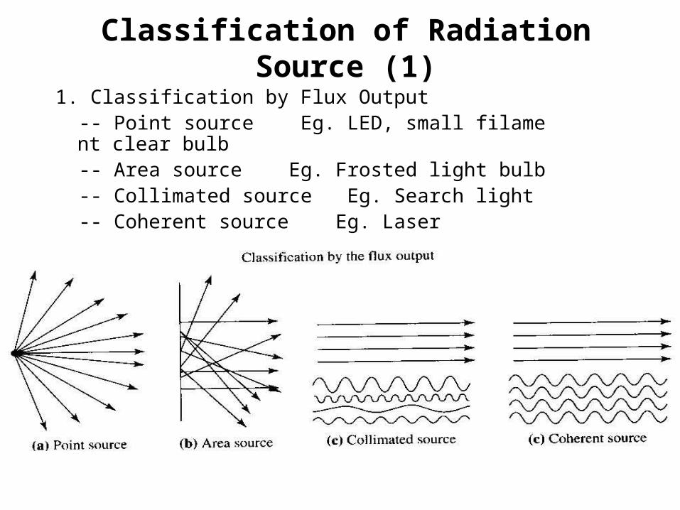
Classification of Radiation Source (1)
1. Classification by Flux Output -- Point source Eg. LED, small filament clear bulb -- Area source Eg. Frosted light bulb -- Collimated source Eg. Search light -- Coherent source Eg. Laser

Classification of Radiation Source (2)
2. Classification by Wavelength and Color (in visible region)
-- Hue (色相 ) Eg. blue , red , green (color)
-- Saturation (飽和度或彩度 ) Eg. pink—red with less saturation (purity)
-- Intensity (強度 ) Eg. flux density of a radiating source
Note : Primary colors : Red (700nm) , Green (546nm) , Blue (440nm)
Note : Chroma (彩色度 ) : combination of hue and saturation
C=R+G+B , where G , R , B are primary flux component

Classification of Radiation Source (3)
3. Classification by radiation spectrum
-- Continuous spectrum Eg. thermally excited source incandescent bulb)
-- Line spectrum Eg. gas discharge and phosphorescent source (螢光 )
-- Single wavelength Eg. source radiated only in a narrow band of wavelength (LED)
-- Mono chromatic source Eg. lasers
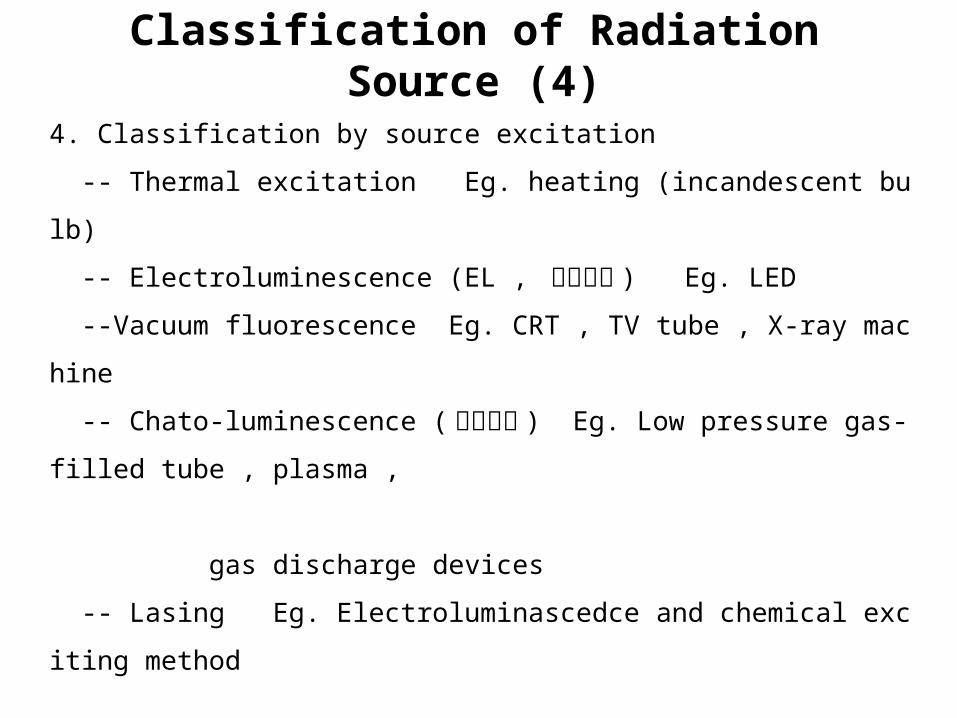
Classification of Radiation Source (4)
4. Classification by source excitation
-- Thermal excitation Eg. heating (incandescent bulb)
-- Electroluminescence (EL , 場致發光 ) Eg. LED
--Vacuum fluorescence Eg. CRT , TV tube , X-ray machine
-- Chato-luminescence (閃光發光 ) Eg. Low pressure gas-filled tube , plasma ,
gas discharge devices
-- Lasing Eg. Electroluminascedce and chemical exciting method
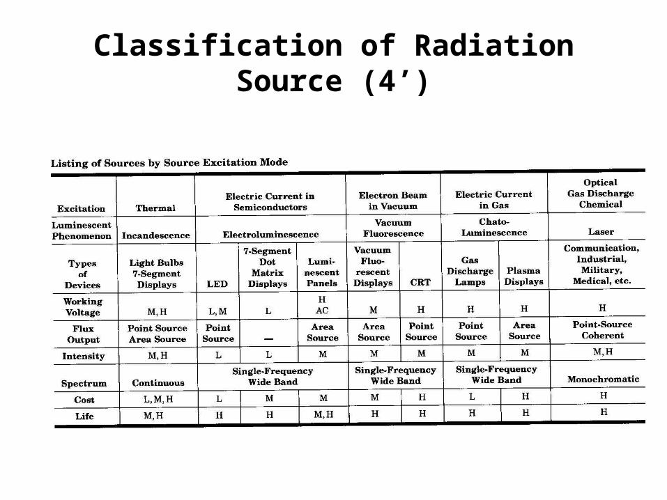
Classification of Radiation Source (4’)
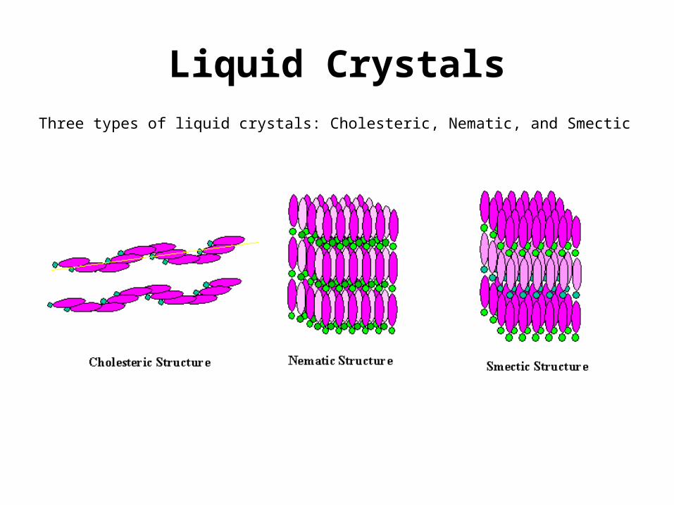
Liquid Crystals
Three types of liquid crystals: Cholesteric, Nematic, and Smectic
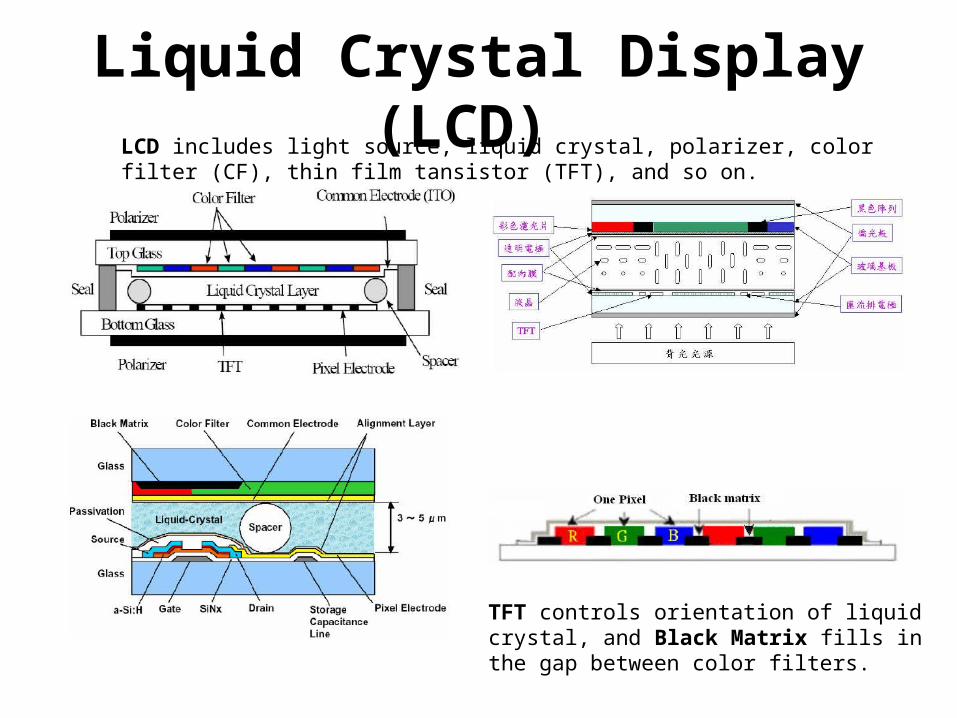
Liquid Crystal Display (LCD) LCD includes light source, liquid crystal, polarizer, color filter (CF), thin film tansistor (TFT), and so on.
TFT controls orientation of liquid crystal, and Black Matrix fills in the gap between color filters.
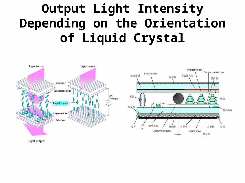
Output Light Intensity Depending on the Orientation of Liquid Crystal

Colorful PixelThe pixels are addressed in rows and columns, reducing the connection complexity. The column and row wires attach to transistor switches, one for each pixel.
Controlling color filter to adjust the transmissions of three primary colors, one can obtain various colors.

Colorful Pixel (Cont’)
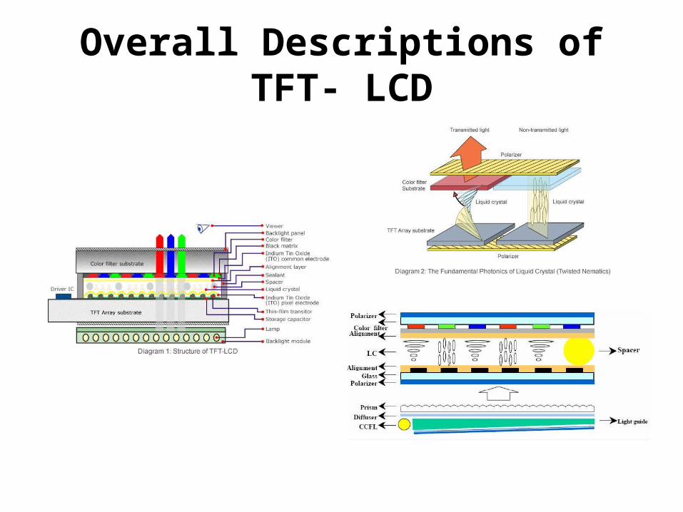
Overall Descriptions of TFT- LCD

TFT-LCD Component

Array/Cell Structure & Equivalent Circuit

Function of TFT Devices
• In the TFT-LCD, TFT device acts as a switch to conduct electric current charging the LC capacitor and storage capacitor.
• When the TFT device is turned on, the signal is written (recorded) into the LC capacitor. With TFT turned-off, the signal will be locked on the LC capacitor and prevent it from being leaky.

Passive Matrix Liquid Crystal Display (PMLCD) and Active Matrix Liquid Crystal Display (AMLCD)
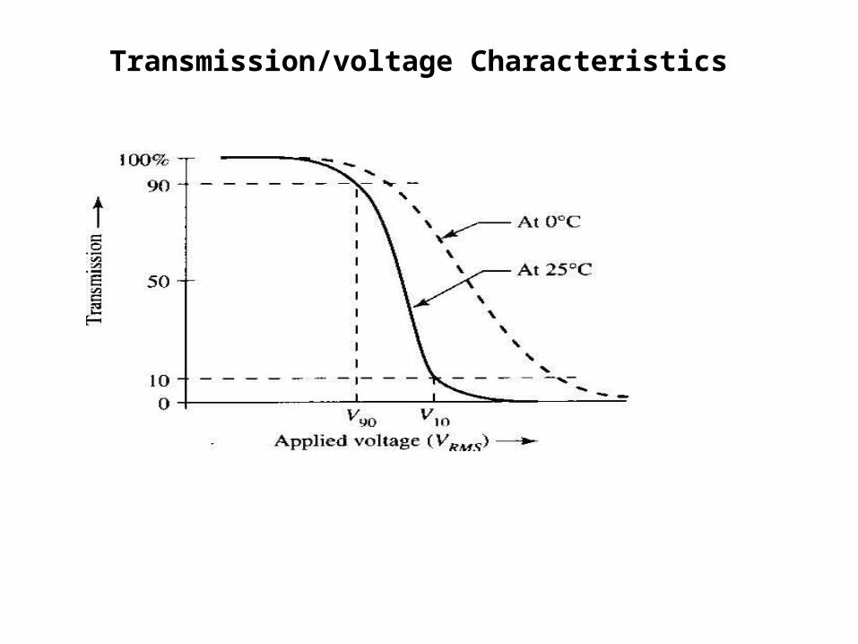
Transmission/voltage Characteristics
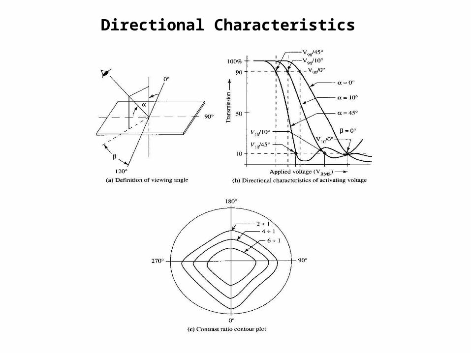
Directional Characteristics
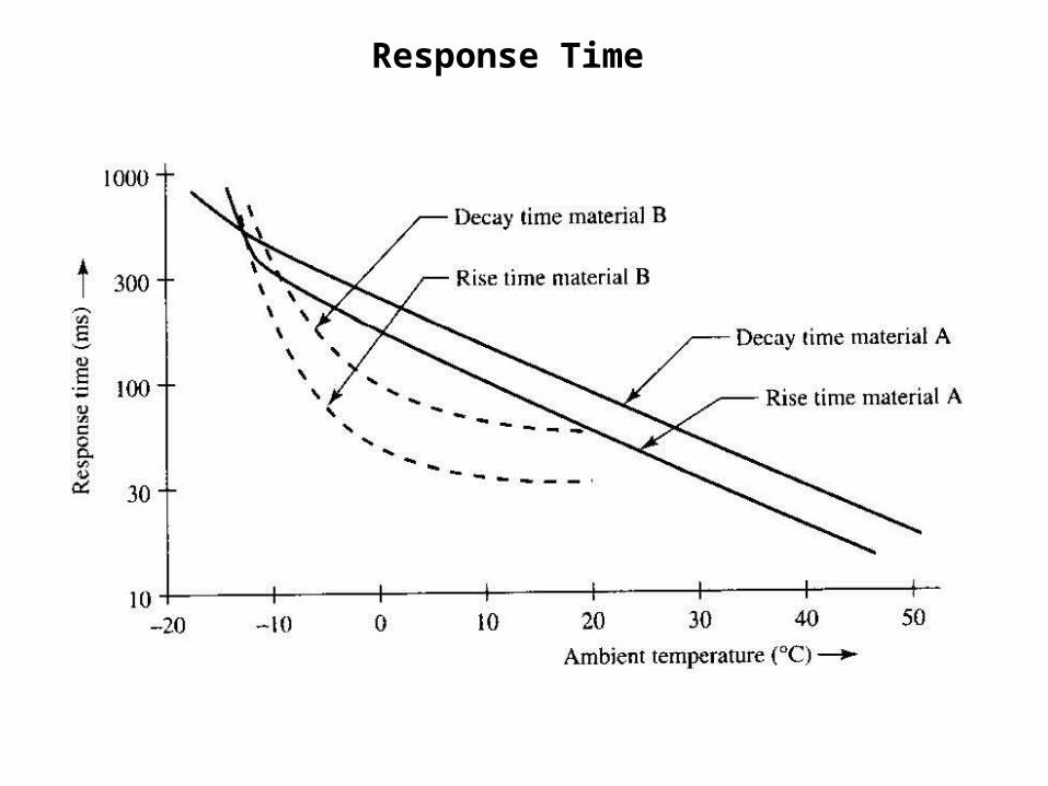
Response Time

Contrast
Note : To design a display with maximum contrast or contrast ratio
)(cd/m luminance sourceor object :
)(cd/m luminance backgroung:
10 ,
2
2
o
B
o
BO
L
L
CL
LLC
For passive display (eg: LCD)
)(cd/m luminance sourceor object :
)(cd/m luminance backgroung:
1 ,
2
2
o
B
B
o
L
L
CL
LC
For active display (eg: LED)

Brightness : Perception of Luminance

Plasma Display
Plasma display panel
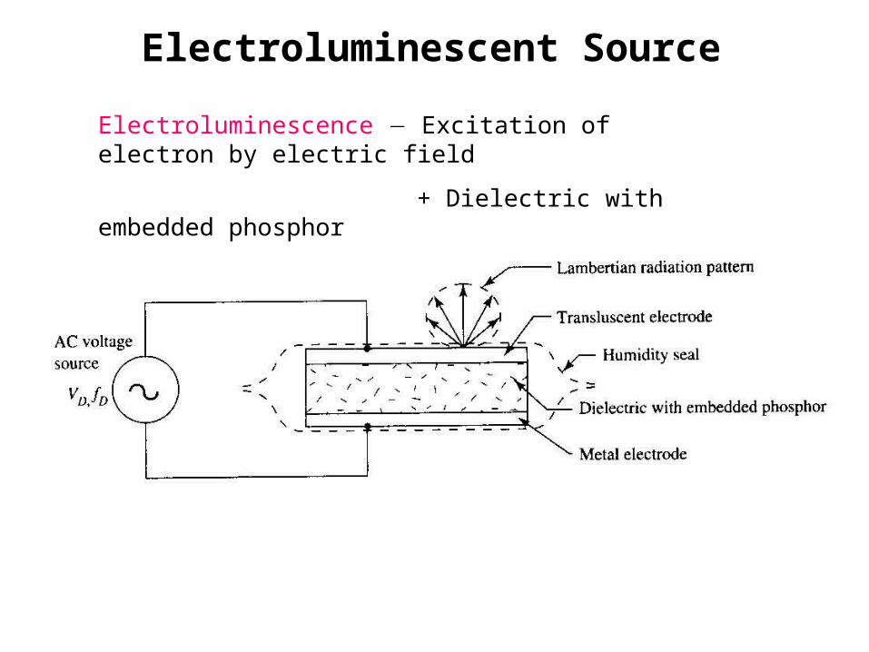
Electroluminescent Source
Electroluminescence Excitation of electron by electric field
+ Dielectric with embedded phosphor
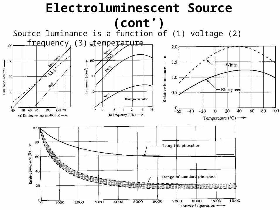
Electroluminescent Source (cont’)Source luminance is a function of (1) voltage (2) frequency (3) temperature
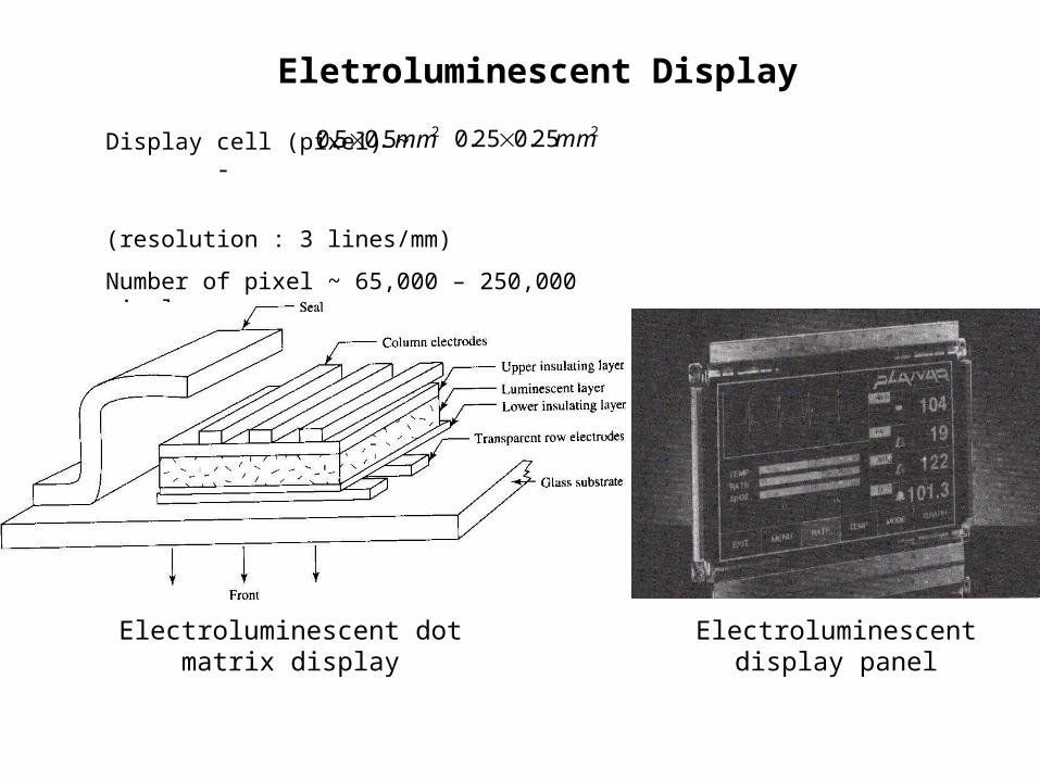
Eletroluminescent Display
Display cell (pixel) ~ -
(resolution : 3 lines/mm)
Number of pixel ~ 65,000 – 250,000 pixels
25.05.0 mm 225.025.0 mm
Electroluminescent dot matrix display Electroluminescent display panel

Vacuum Fluorescent SourceVacuum fluorescent
high-speed electron + phosphor
Vacuum fluorescent display
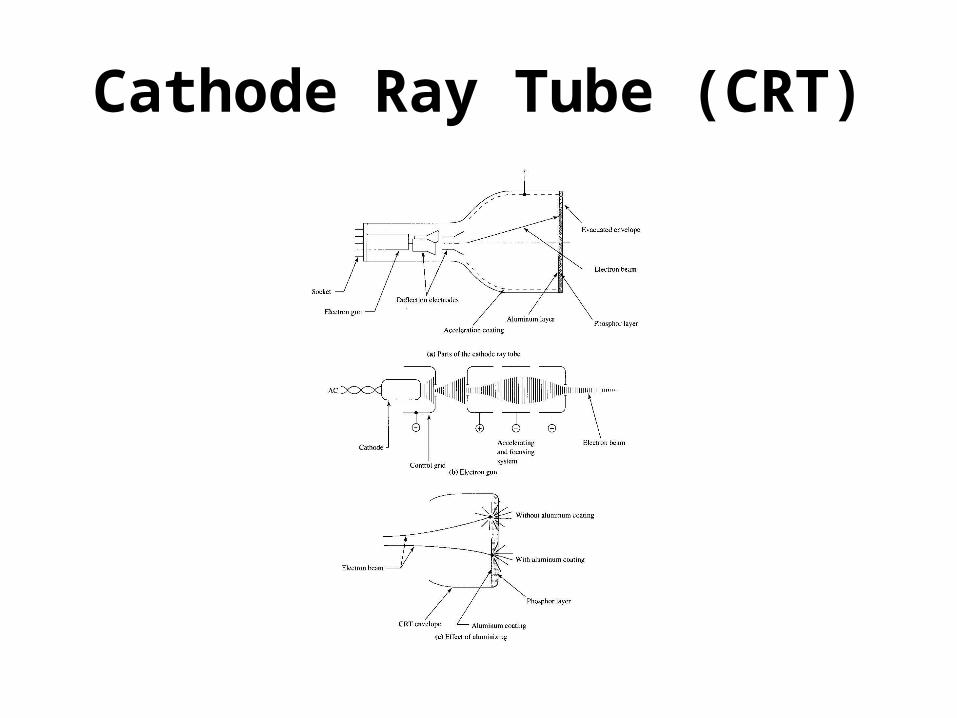
Cathode Ray Tube (CRT)
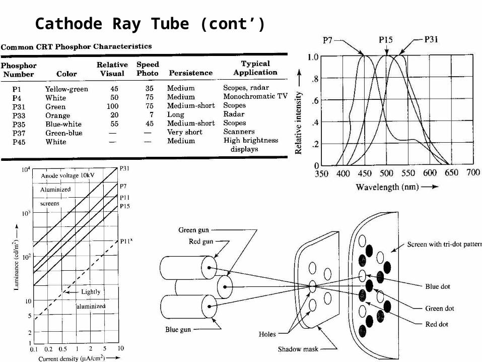
Cathode Ray Tube (cont’)
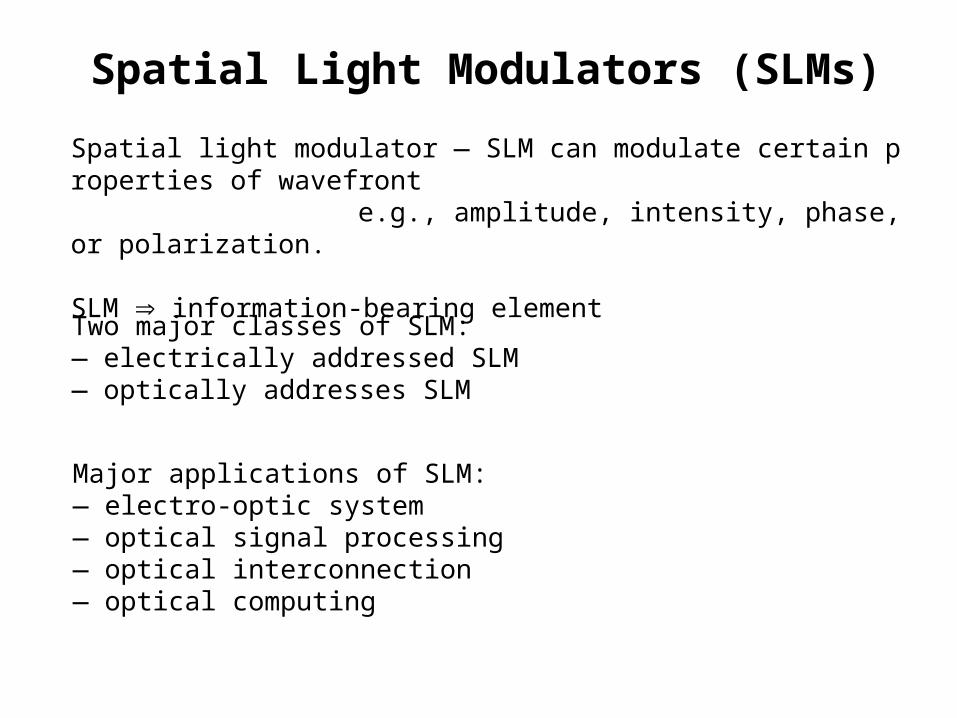
Spatial Light Modulators (SLMs)
Two major classes of SLM:— electrically addressed SLM— optically addresses SLM
Spatial light modulator — SLM can modulate certain properties of wavefronte.g., amplitude, intensity, phase, or polarization.
SLM information-bearing element
Major applications of SLM:— electro-optic system— optical signal processing— optical interconnection— optical computing
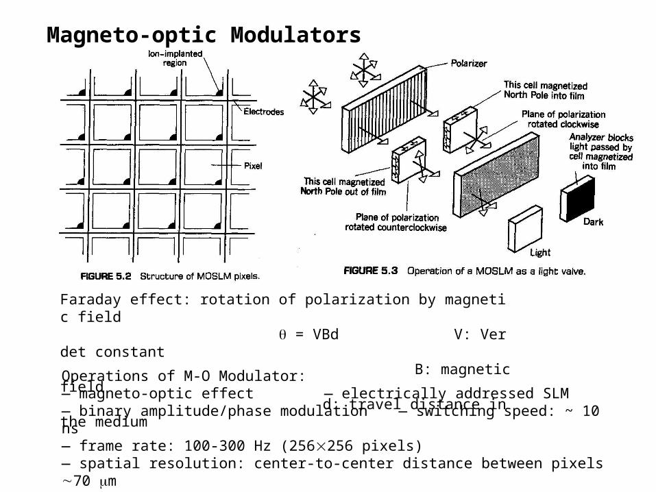
Magneto-optic Modulators
Faraday effect: rotation of polarization by magnetic field = VBd V: Verdet constant
B: magnetic fieldd: travel distance in the medium
Operations of M-O Modulator:— magneto-optic effect — electrically addressed SLM— binary amplitude/phase modulation — switching speed: ~ 10 ns— frame rate: 100-300 Hz (256256 pixels)— spatial resolution: center-to-center distance between pixels 70 m— contract ratio: 300:1@633nm— transmittance: 5%
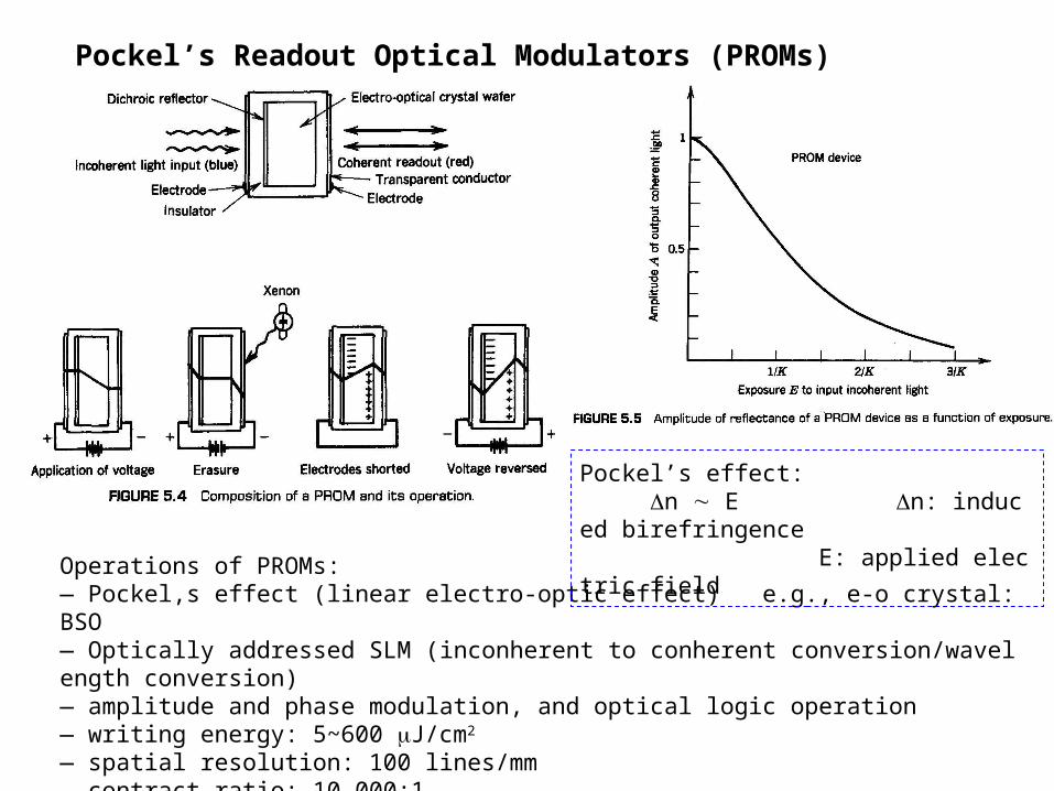
Pockel’s Readout Optical Modulators (PROMs)
Operations of PROMs:— Pockel,s effect (linear electro-optic effect) e.g., e-o crystal: BSO— Optically addressed SLM (inconherent to conherent conversion/wavelength conversion)— amplitude and phase modulation, and optical logic operation— writing energy: 5~600 J/cm2
— spatial resolution: 100 lines/mm— contract ratio: 10,000:1— write-read-erase cycle: 30 frames/s (at video rate; write and erase times < 1ms)
Pockel’s effect: n E n: induced birefringence
E: applied electric field
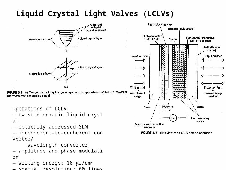
Liquid Crystal Light Valves (LCLVs)
Operations of LCLV:— twisted nematic liquid crystal— optically addressed SLM— inconherent-to-conherent converter/ wavelength converter— amplitude and phase modulation— writing energy: 10 J/cm2
— spatial resolution: 60 lines/mm— contract ratio: 100:1— readout time: 10 ms
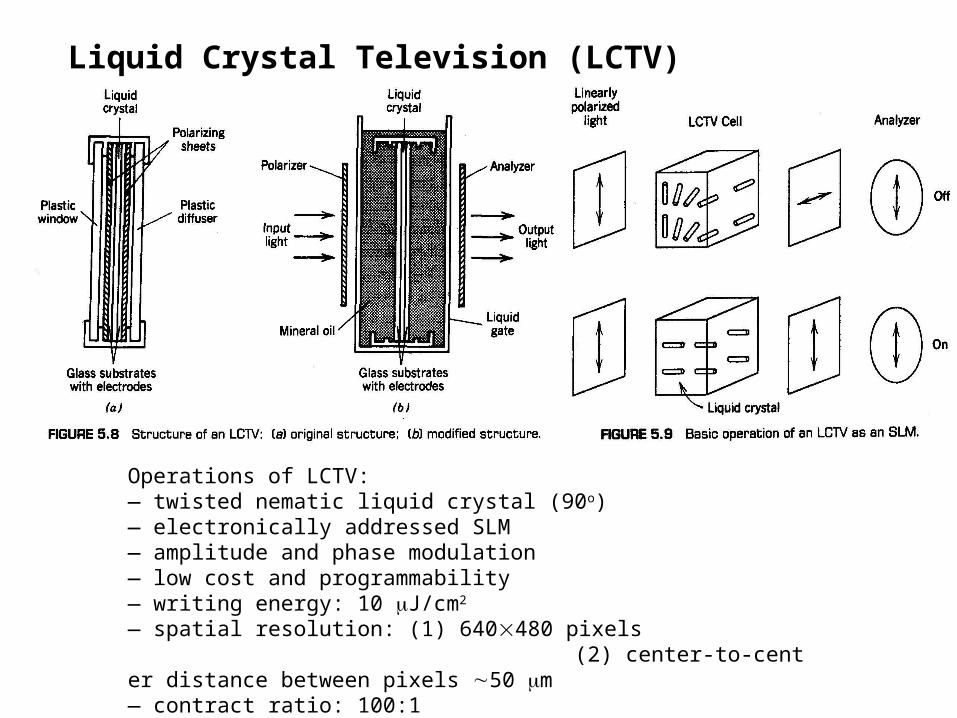
Liquid Crystal Television (LCTV)
Operations of LCTV:— twisted nematic liquid crystal (90o)— electronically addressed SLM— amplitude and phase modulation— low cost and programmability— writing energy: 10 J/cm2
— spatial resolution: (1) 640480 pixels (2) center-to-center distance between pixels 50 m— contract ratio: 100:1— frame rate: 60 Hz
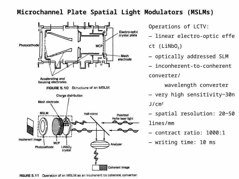
Microchannel Plate Spatial Light Modulators (MSLMs)
Operations of LCTV:
— linear electro-optic effect (LiNbO3)
— optically addressed SLM
— inconherent-to-conherent converter/
wavelength converter
— very high sensitivity~30nJ/cm2
— spatial resolution: 20~50 lines/mm
— contract ratio: 1000:1
— writing time: 10 ms

Photoplastic Devices
Operations of photoplastic device:
— Charge Exposure Recharge Develop Erase
— phase modulation/phase grating
— light sensitivity~ J/cm2
— spatial resolution: ~2000 lines/mm
— diffraction efficiency: ~ 10% @60 J/cm2
— lifetime: 300-2000 cycles
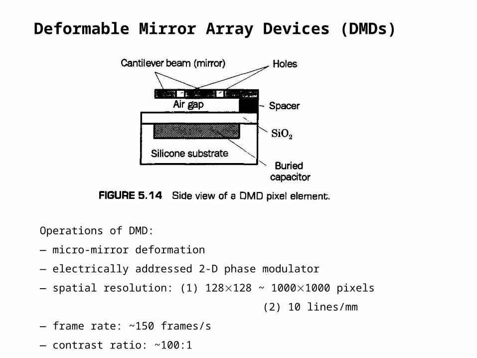
Deformable Mirror Array Devices (DMDs)
Operations of DMD:
— micro-mirror deformation
— electrically addressed 2-D phase modulator
— spatial resolution: (1) 128128 ~ 10001000 pixels
(2) 10 lines/mm
— frame rate: ~150 frames/s
— contrast ratio: ~100:1
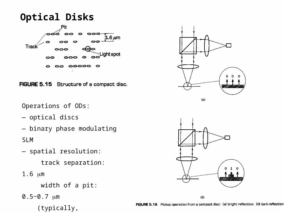
Optical Disks
Operations of ODs:
— optical discs
— binary phase modulating SLM
— spatial resolution:
track separation: 1.6 m
width of a pit: 0.5~0.7 m
(typically, /NA1.55)
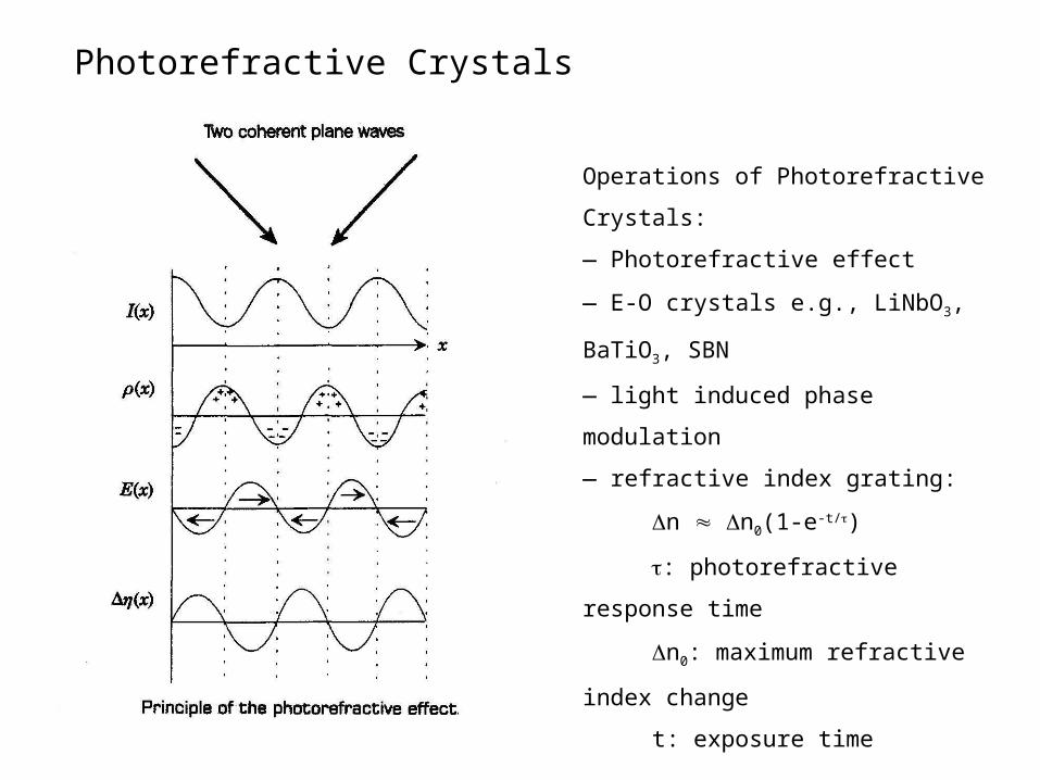
Photorefractive Crystals
Operations of Photorefractive Crystals:
— Photorefractive effect
— E-O crystals e.g., LiNbO3, BaTiO3, SBN
— light induced phase modulation
— refractive index grating:
n n0(1-e-t/)
: photorefractive response time
n0: maximum refractive index change
t: exposure time