8. design of adders - university of texas at austinjaa/lectures/8-1.pdf · 2017-09-26 · sklansky...
TRANSCRIPT

8. Design of Adders
Jacob Abraham
Department of Electrical and Computer EngineeringThe University of Texas at Austin
VLSI DesignFall 2017
September 27, 2017
ECE Department, University of Texas at Austin Lecture 8. Design of Adders Jacob Abraham, September 27, 2017 1 / 34

Review Example
Find the (worst case) logical efforts of the different inputs in theCMOS circuit below. For an input, can the corresponding“worst-case” inverter be determined by inspection?
Question: What would be the difference in the delay determinedusing Elmore Delay and that computed using Logical Effort?
ECE Department, University of Texas at Austin Lecture 8. Design of Adders Jacob Abraham, September 27, 2017 1 / 34
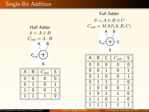
Single-Bit Addition
Half AdderS = A⊕BCout = A ·B
A B Cout S
0 0 0 0
0 1 0 1
1 0 0 1
1 1 1 0
Full Adder
S = A⊕B ⊕ CCout = MAJ(A,B,C)
A B C Cout S
0 0 0 0 0
0 0 1 0 1
0 1 0 0 1
0 1 1 1 0
1 0 0 0 1
1 0 1 1 0
1 1 0 1 0
1 1 1 1 1ECE Department, University of Texas at Austin Lecture 8. Design of Adders Jacob Abraham, September 27, 2017 2 / 34

Full Adder Design I
Brute force implementation from equationsS = A⊕B ⊕ CCout = MAJ(A,B,C)
ECE Department, University of Texas at Austin Lecture 8. Design of Adders Jacob Abraham, September 27, 2017 3 / 34

Full Adder Design II
Factor S in terms of Cout
S = A ·B · C + (A+B + C) · Cout
Critical path is usually C to Cout in ripple adder
ECE Department, University of Texas at Austin Lecture 8. Design of Adders Jacob Abraham, September 27, 2017 4 / 34

Layout of Full Adder
Clever layout circumvents usual line of diffusion
Use wide transistors on critical pathEliminate output inverters
ECE Department, University of Texas at Austin Lecture 8. Design of Adders Jacob Abraham, September 27, 2017 5 / 34

Full Adder Design III
Complementary Pass Transistor Logic (CPL)
Slightly faster, but more area
ECE Department, University of Texas at Austin Lecture 8. Design of Adders Jacob Abraham, September 27, 2017 6 / 34

Ripple Carry Adder
Simplest design: cascade full adders
Critical path goes from Cin to Cout
Design full adder to have fast carry (small delay for carrysignal)
ECE Department, University of Texas at Austin Lecture 8. Design of Adders Jacob Abraham, September 27, 2017 7 / 34

Deal with Inversions to Speed Up Carry Path
Critical path passes through majority gate
Built from minority + inverterEliminate inverter and use inverting full adder
ECE Department, University of Texas at Austin Lecture 8. Design of Adders Jacob Abraham, September 27, 2017 8 / 34

Carry Propagate Adders
N-bit adder called CPA
Each sum bit depends on all previous carriesHow do we compute all these carries quickly?
ECE Department, University of Texas at Austin Lecture 8. Design of Adders Jacob Abraham, September 27, 2017 9 / 34
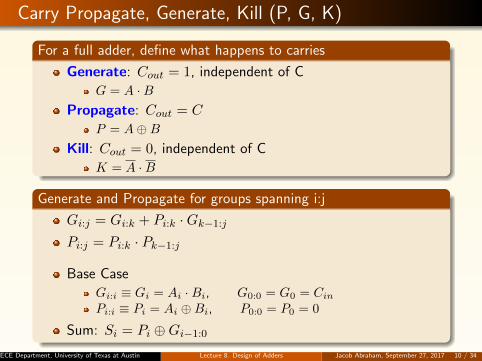
Carry Propagate, Generate, Kill (P, G, K)
For a full adder, define what happens to carries
Generate: Cout = 1, independent of C
G = A ·BPropagate: Cout = C
P = A⊕B
Kill: Cout = 0, independent of C
K = A ·B
Generate and Propagate for groups spanning i:j
Gi:j = Gi:k + Pi:k ·Gk−1:j
Pi:j = Pi:k · Pk−1:j
Base Case
Gi:i ≡ Gi = Ai ·Bi, G0:0 = G0 = Cin
Pi:i ≡ Pi = Ai ⊕Bi, P0:0 = P0 = 0
Sum: Si = Pi ⊕Gi−1:0
ECE Department, University of Texas at Austin Lecture 8. Design of Adders Jacob Abraham, September 27, 2017 10 / 34

Carry Propagate, Generate, Kill (P, G, K)
For a full adder, define what happens to carries
Generate: Cout = 1, independent of C
G = A ·BPropagate: Cout = C
P = A⊕B
Kill: Cout = 0, independent of C
K = A ·B
Generate and Propagate for groups spanning i:j
Gi:j = Gi:k + Pi:k ·Gk−1:j
Pi:j = Pi:k · Pk−1:j
Base Case
Gi:i ≡ Gi = Ai ·Bi, G0:0 = G0 = Cin
Pi:i ≡ Pi = Ai ⊕Bi, P0:0 = P0 = 0
Sum: Si = Pi ⊕Gi−1:0
ECE Department, University of Texas at Austin Lecture 8. Design of Adders Jacob Abraham, September 27, 2017 11 / 34

PG Logic
ECE Department, University of Texas at Austin Lecture 8. Design of Adders Jacob Abraham, September 27, 2017 12 / 34

Ripple Carry Adder Revisited in the PG Framework
Gi:0 = Gi + Pi ·Gi−1:0
ECE Department, University of Texas at Austin Lecture 8. Design of Adders Jacob Abraham, September 27, 2017 13 / 34

Ripple Carry PG Diagram
tripple = tpg + (N − 1)tAO + txor
ECE Department, University of Texas at Austin Lecture 8. Design of Adders Jacob Abraham, September 27, 2017 14 / 34

PG Diagram Notation
ECE Department, University of Texas at Austin Lecture 8. Design of Adders Jacob Abraham, September 27, 2017 15 / 34

Carry-Skip Adder
Carry-ripple is slow through all N stages
Carry-skip allows carry to skip over groups of n bits
Decision based on n-bit propagate signal
ECE Department, University of Texas at Austin Lecture 8. Design of Adders Jacob Abraham, September 27, 2017 16 / 34

Carry-Skip PG Diagram
For k n-bit groups (N = nk)tskip = tpg + [2(n− 1) + (k − 1)] tAO + txor
ECE Department, University of Texas at Austin Lecture 8. Design of Adders Jacob Abraham, September 27, 2017 17 / 34

Variable Group Size
Delay grows as O(√N)
ECE Department, University of Texas at Austin Lecture 8. Design of Adders Jacob Abraham, September 27, 2017 18 / 34

Carry-Lookahead Adder (CLA)
Carry-lookahead adder computes Gi:0 for many bits in parallel
Uses higher-valency cells with more than two inputs
ECE Department, University of Texas at Austin Lecture 8. Design of Adders Jacob Abraham, September 27, 2017 19 / 34

CLA PG Diagram
Higher Valency Cells
ECE Department, University of Texas at Austin Lecture 8. Design of Adders Jacob Abraham, September 27, 2017 20 / 34
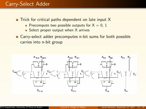
Carry-Select Adder
Trick for critical paths dependent on late input X
Precompute two possible outputs for X = 0, 1Select proper output when X arrives
Carry-select adder precomputes n-bit sums for both possiblecarries into n-bit group
ECE Department, University of Texas at Austin Lecture 8. Design of Adders Jacob Abraham, September 27, 2017 21 / 34

Carry-Increment Adder
Factor initial PG andfinal XOR out ofcarry-select
tincrement = tpg +[(n− 1) + (k − 1)] tAO+txor
Variable Group Size
Buffer non-criticalsignals to reducebranching effort
ECE Department, University of Texas at Austin Lecture 8. Design of Adders Jacob Abraham, September 27, 2017 22 / 34
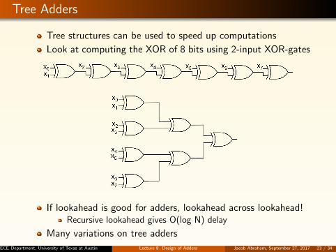
Tree Adders
Tree structures can be used to speed up computations
Look at computing the XOR of 8 bits using 2-input XOR-gates
If lookahead is good for adders, lookahead across lookahead!Recursive lookahead gives O(log N) delay
Many variations on tree adders
ECE Department, University of Texas at Austin Lecture 8. Design of Adders Jacob Abraham, September 27, 2017 23 / 34

Brent-Kung Adder
ECE Department, University of Texas at Austin Lecture 8. Design of Adders Jacob Abraham, September 27, 2017 24 / 34

Sklansky Adder
ECE Department, University of Texas at Austin Lecture 8. Design of Adders Jacob Abraham, September 27, 2017 25 / 34

Kogge-Stone Adder
ECE Department, University of Texas at Austin Lecture 8. Design of Adders Jacob Abraham, September 27, 2017 26 / 34

Tree Adder Taxonomy
Ideal N-bit tree adder would have
L = log N logic levelsFanout never exceeding 2No more than one wiring track between levels
Describe adder with 3-D taxonomy (l, f, t)
Logic levels: L+ lFanout: 2f + 1Wiring tracks: 2t
Known tree adders sit on plane defined by l + f + t = L− 1
ECE Department, University of Texas at Austin Lecture 8. Design of Adders Jacob Abraham, September 27, 2017 27 / 34

Tree Adder Taxonomy, Cont’d
ECE Department, University of Texas at Austin Lecture 8. Design of Adders Jacob Abraham, September 27, 2017 28 / 34

Han-Carlson Adder
ECE Department, University of Texas at Austin Lecture 8. Design of Adders Jacob Abraham, September 27, 2017 29 / 34

Brent-Kung Adder
ECE Department, University of Texas at Austin Lecture 8. Design of Adders Jacob Abraham, September 27, 2017 30 / 34

Knowles [2,1,1,1] Adder
ECE Department, University of Texas at Austin Lecture 8. Design of Adders Jacob Abraham, September 27, 2017 31 / 34

Ladner-Fischer Adder
ECE Department, University of Texas at Austin Lecture 8. Design of Adders Jacob Abraham, September 27, 2017 32 / 34

Tree Adder Taxonomy Revisited
ECE Department, University of Texas at Austin Lecture 8. Design of Adders Jacob Abraham, September 27, 2017 33 / 34

Summary of Adders
Adder architectures offer area/power/delay tradeoffs
Choose the best one for your application
Architecture Classifi-cation
Logic lev-els
Max.fanout
Tra-cks
Cells
Ripple Carry N − 1 1 1 N
Carry-skip(n=4) N/4 + 5 2 1 1.25N
Carry-inc.(n=4) N/4 + 2 4 1 2N
Brent-Kung (L-1,0,0) 2log2N−1 2 1 2N
Sklansky (0,L-1,0) log2N N/2+1 1 0.5Nlog2N
Kogge-Stone (0,0,L-1) log2N 2 N/2 Nlog2N
ECE Department, University of Texas at Austin Lecture 8. Design of Adders Jacob Abraham, September 27, 2017 34 / 34