7xv5655-0ba00-hub manual a3 en
TRANSCRIPT

Copyright SIEMENS AG 2008
7XV5655-0BA00
Manual C53000-G1176-C174-3
Application Instructions
Serial Hub
Ethernet hub for transmission of serial data or protocols from devices with an RS232/RS485/FO interface via Ethernet

English 7XV5655-0BA00
2 / 53 C53000-G1176-C174-3
CONTENTS GENERAL INFORMATION..................................................................................................................................3
APPLICATION........................................................................................................................................................8
DESCRIPTION OF INTERFACES, DIP SWITCHES AND DISPLAYS........................................................11
MOUNTING AND COMMISSIONING ..............................................................................................................16
PRACTICAL SAFETY INFORMATION...........................................................................................................19
PREPARING THE OPERATING PC OR SERVICE NOTEBOOK................................................................20
THE CONFIGURATION TOOL .........................................................................................................................27
OPTIMISING DATA TRANSFER ......................................................................................................................38
SELECTING A PASSWORD-PROTECTED SERIAL HUB............................................................................40
PIN ASSIGNMENT ...............................................................................................................................................41
TECHNICAL DATA .............................................................................................................................................44
DIMENSIONS ........................................................................................................................................................49
ORDERING INFORMATION .............................................................................................................................50

English 7XV5655-0BA00
3 / 53 C53000-G1176-C174-3
General Information This manual contains the information that is necessary for proper and safe operation of the products described. This manual is intended for technically qualified personnel having received special training in, or having special knowledge of protection, measurement and control engineering, hereinafter called automation engineering. The knowledge and correct application of the warnings and instructions contained in this manual are prerequisites to safe installation and commissioning of this product, as well as to proper and safe operation and maintenance. Only qualified personnel as defined overleaf have the special knowledge required for correct interpretation of the general safety information and warnings given in this manual, and for their application to the task in hand. This manual is included in the scope of delivery. For reasons of clarity, however, it does not purport to contain every detail of all versions of the product described, nor can it deal with all possible cases of erection, operation or maintenance. If further information is desired or if special problems arise that are not treated adequately in this document, it is possible to obtain additional details from your local Siemens office or from the addresses stated on the back of this manual. We should also like to point out that the contents of this product documentation are not part of any previous or existing agreement or legal relationship, nor are they apt to modify such an agreement or relationship. All obligations incurred by Siemens result from the purchase contract, which also contains the complete and solely applicable warranty conditions. Contractual warranty conditions are neither extended nor restricted by the contents of this document. Disclaimer of Liability We have checked the contents of this document and every effort has been made to ensure that the descriptions of both the hardware and software are as accurate as possible. However, since deviations cannot be ruled out entirely, we do not accept liability for complete conformity or for any errors or omissions. The information given in this document is reviewed regularly and any necessary corrections will be included in subsequent editions. We are grateful for any improvements that you care to suggest. Subject to technical modifications without notice. Release 3.00.00
Copyright Copyright © Siemens AG 2008. All rights reserved.
The reproduction, transmission or use of this document or its contents is not permitted without express written authority.
Offenders will be liable for damages. All rights, including rights created by patent grant or registration of a utility model or design, are reserved.
Registered Trademarks SIPROTEC, SINAUT, SICAM and DIGSI® are registered trademarks of Siemens AG. Other designations in this manual might be trademarks whose use by third parties for their own purposes would infringe the rights of the owner.

English 7XV5655-0BA00
4 / 53 C53000-G1176-C174-3
Statement of Conformity
This product complies with the directive of the Council of the European Communities on the approximation of the laws of the member states relating to electromagnetic compatibility (EMC Council Directive 2004/108/EC) and concerning electrical equipment for use within specified voltage limits (Low Voltage Directive 2006/95/EC). This conformity has been proved by tests performed according to the Council Directives in agreement with the generic standards EN 61000-6-2 and EN 61000-6-4 (for EMC Directive) and with the standard EN 60255-6 (for Low Voltage Directive) by Siemens AG. The device is designed and manufactured for application in industriel environment. The product conforms with the international standards of IEC 60255 and the German regulations of VDE 0435.

English 7XV5655-0BA00
5 / 53 C53000-G1176-C174-3
Instructions and Warnings The information and warnings in this manual must be observed for your safety and to ensure an appropriate service life of the device. The following terms and definitions are used:
DANGER means that death, severe bodily injury or substantial material damage will occur if the appropriate precautions are not taken.
Warning means that death, severe bodily injury or substantial material damage could occur if the appropriate precautions are not taken.
Caution indicates that minor bodily injury or material damage could result if appropriate precautions are not taken. This applies in particular to damage on or in the device itself and resulting consequential damage.
Note contains important information about the product or a part of the document to which special attention is drawn.
Warning The 7XV5655-0BA00 is specifically intended for installation in a switchgear cubicle or distribution box. After installation, the entire area around the terminals must be covered. Only then is the device sufficiently protected against impermissible contact with live parts.

English 7XV5655-0BA00
6 / 53 C53000-G1176-C174-3
Warning! Hazardous voltages are present in this electrical equipment during operation. Severe personal injury or property damage can result if the device is not handled properly. Only qualified personnel should work on or around this equipment. The personnel must be thoroughly familiar with all warnings and maintenance procedures of this manual as well as the safety regulations. Successful and safe operation of the unit is dependent on proper transportation, storage, erection and assembly and the observance of the warnings and instructions of the manual. In particular, the general installation and safety regulations for work in power current plants (e.g. ANSI, IEC, EN, DIN, or other national and international regulations) must be observed. Failure to observe these precautions can result in death, personal injury, or serious material damage. Never look into fibre-optic components or the ends of the fibres.
Qualified Personnel for the purposes of this manual and the warnings on the product itself, are persons who are acquainted with the erection, installation, commissioning and operation of the device and who possess the appropriate qualifications for their task, such as
Training and instruction to energise, de-energise, clear, earth and tag circuits and equipment in accordance with established safety practice.
Training or instruction in accordance with established safety practice for care and use of certain safety equipment.
Training in rendering first aid.

English 7XV5655-0BA00
7 / 53 C53000-G1176-C174-3
Scope of Supply • Serial Hub for DIN rail mounting
• Gender changer, 9-way, male-male
• CD with manual and configuration tool
• Installation Instructions
Unpacking and Repacking The devices are packed at the factory to meet the requirements of IEC 60255–21. Unpacking and repacking must be performed with the usual care, without force and only with the aid of suitable tools. Visually check the device immediately upon arrival for correct mechanical condition. Please also always follow instructions if they are supplied with the device. The shipping packaging can be reused in the same manner for further shipment. The storage packaging of individual devices is not sufficient for shipping. If other packaging is used, the shock requirements acc. to IEC 60255–21–1 Class II and IEC 60255–21–2 Class 1 must be met. The device should be in the final operating area for a minimum of two hours before the power source is first applied. This gives the device time to attain temperature equilibrium, thus avoiding dampness and condensation.
Storage SIPROTEC® devices and associated assemblies should be stored in a dry and clean place. The device and its replacement modules must be stored within the temperature range –10 °C to +55 °C. The relative humidity must not cause condensation or ice. To avoid premature ageing of the electrolyte capacitors in the power supply unit, a temperature range of +10 °C to +35 °C (+50 °F to +95 °F) is recommended for storage. After extended storage, the power supply of the device should be energised, approximately every two years, for one or two days to regenerate the electrolytic capacitors in the power supply unit. This should also be done before the device is put into service.
English 7XV5655-0BA00
8 / 53 C53000-G1176-C174-3
Application
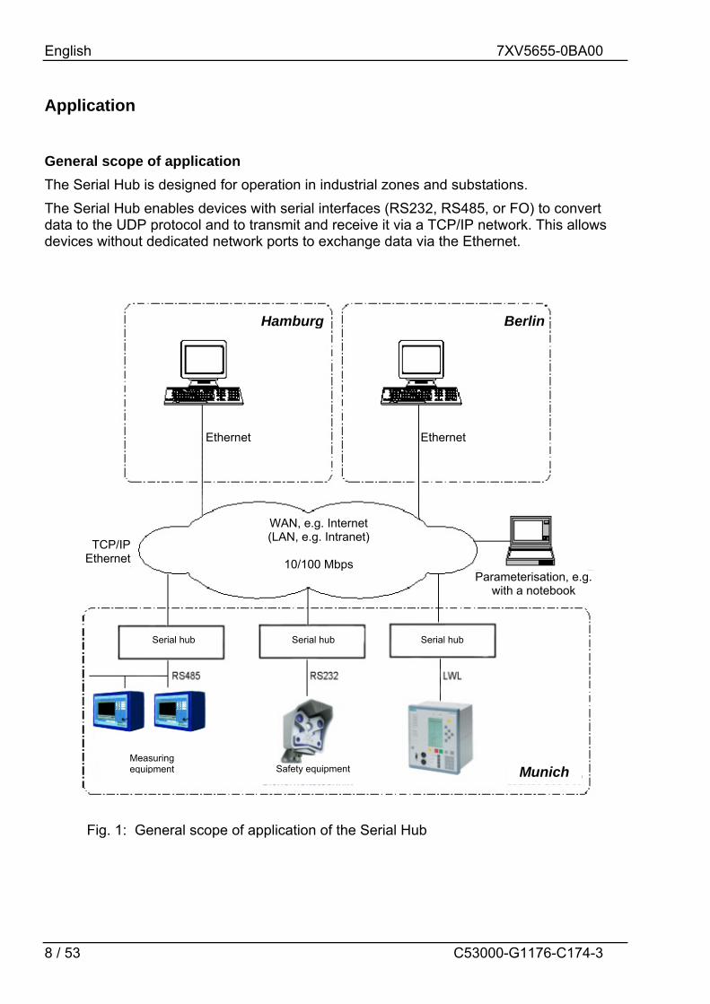
General scope of application The Serial Hub is designed for operation in industrial zones and substations. The Serial Hub enables devices with serial interfaces (RS232, RS485, or FO) to convert data to the UDP protocol and to transmit and receive it via a TCP/IP network. This allows devices without dedicated network ports to exchange data via the Ethernet.
Ethernet Ethernet
WAN, e.g. Internet (LAN, e.g. Intranet)
10/100 Mbps
Parameterisation, e.g. with a notebook
Serial hub Serial hub Serial hub
Measuring equipment Safety equipment Munich
Hamburg Berlin
TCP/IPEthernet
Fig. 1: General scope of application of the Serial Hub

English 7XV5655-0BA00
9 / 53 C53000-G1176-C174-3
Application in Substations Using a 7XV5655-0BA00 Serial Hub with a fixed IP address, one or more SIPROTEC protection units can exchange serial data via an Ethernet network. On the operating PC, a configuration tool is used to link virtual COM port with the IP address of a Serial Hub. Using DIGSI 4 it is then possible to operate all protection units connected to the Serial Hub via the virtual COM port. The protection unit is connected to the Serial Hub via its serial interface. The serial interface types available are RS232 or RS485 (same connector), and FO (fibre optical). The serial data are converted to the UDP protocol with error detection and correction as useful data in the Serial Hub and transmitted via the TCP/IP Ethernet network. The hub meets the requirement for standard compliant, uninterrupted transmission of serial DIGSI® or IEC 60870-5-103/101 frames via the network by listening into the serial frame traffic and sending the serial IEC telegrams via the Ethernet packed in blocks. Both full-duplex and half-duplex data transmission (RS485) are possible. The serial control lines are not supported. The Serial Hub can be configured with password protection. Configuration of the Serial Hub is performed using the configuration tool included in the scope of supply.
RS485-Bus-Cable 7XV5103
SIPROTEC SIEMENS
L1 402,1A Max450.1AL2 402,1A Max450.1AL3 402,1A Max450.1AE 00.0A
Anr. L1 Anr. L2 Anr. L3 Anr. Erde Automat
RUN ERROR
LAN
FO-Cable 6XV8100
SIPROTEC SIEMENS
L1 402,1A Max450.1AL2 402,1A Max450.1AL3 402,1A Max450.1AE 00.0A
Anr. L1 Anr. L2 Anr. L3 Anr. Erde Automat
RUN ERROR
Router / Switch
DIGSI 4Config-Tool
Patch-Cable
WAN (Private Network)
21 3 4
Ethernet-Hub
7XV5655
5 6up
Ethernet-Hub
7XV5655
Mini-Star-coupler7XV5450
INPUT
L2 402,1A Max450.1AL3 402,1A Max450.1A
L2 402,1A Max450.1AL3 402,1A Max450.1A
7XV5
101
SIPROTEC SIEMENS
L1 402,1A Max450.1AL2 402,1A Max450.1AL3 402,1A Max450.1AE 00.0A
Anr. L1 Anr. L2 Anr. L3 Anr. Erde Automat
RUN ERROR
SIEMENS
RUN ERROR
Anr. L1 Anr. L2
RS485-FOConverter7XV5650
SIEMENS
RUN ERROR
Anr. L1 Anr. L2
7XV5103
Max. 31 SIPROTEC 3 Devices with
RS485-Interface
Max. 4 SIPROTEC 3 Devices with optical Interface
Station-PC for Remote control and Configuration for the Ethernet-Modems
Substation-modem 1
Substation-modem 2
SIPROTEC 4 with Ethernet-
Interface
Max. 31 SIPROTEC 4 Devices with RS485-Interface
Fig. 2: Serial Hub, application in substations

English 7XV5655-0BA00
10 / 53 C53000-G1176-C174-3
Features Protocol detection according to EN 60870-5-101/103 and DIGSI protocol (similar to
IEC60870-5-103), UDP protocol with error detection and correction A 10-Mbit Ethernet interface (10BaseT) to the 10/100 Mbit network. RS232/RS485 (switchable port) or FO interface for data transfer. Serial baudrate and data format to the terminal devices automatically set by the
application, e.g. DIGSI 4 at 2400 Bd to 57.6 kBd (115.2 kBd) with data formats 8N1, 8N2, 8E1.
Reset to default values (factory settings) with INIT button: 9600 baud, 8N1 DIP switch for RS232/RS485 selection and RS485 bus termination and FO idle state Enhanced security possible with password protection LED displays for operating voltage and data traffic are located on the front panel. DIN rail module in the plastic housing with integrated wide-range power supply unit
(24 - 250 V DC and 60 - 230 V AC) permits connection to all common substation batteries or AC power systems.
Protective conductor (PE) connection Easy configuration with the configuration tool

English 7XV5655-0BA00
11 / 53 C53000-G1176-C174-3
Description of Interfaces, DIP Switches and Displays The Serial Hub has the following connectors:
• A switchable RS232/RS485 interface (9-way SubD male connector)
• FO transmitter and receiver port with ST connectors
• 10-Mbit Ethernet connector (10BaseT) for a 10/100 Mbit network
• DIP switches for RS232/RS485 switchover and RS485 termination and for setting the FO idle state
• AC/DC power supply and protective conductor (PE) connection via 3-way screw terminal
Communications Interfaces The RS232/RS485 or FO interfaces are controlled internally by the same processor interface. The electrical interface is selected via the DIP switches. You can choose between RS232 or RS485; the FO interface always works parallel with RS232 or RS485 at the transmitter end and is ORed with RS232/485 at the receiver end, that is, both streams of receive data are unlocked and are received and evaluated with equal priority. To rule out data collisions, the connected protection units are addressed selectively by DIGSI®. This is done via the interface address of the protection units.
RS232 Interface The terminal device (protection unit) (e.g. a SIPROTEC® 4 unit) or a device from the SIEMENS accessory program (e.g. a 7XV5300 or 7XV5450 star coupler for operating two or more SIPROTEC® devices) can be connected directly to the RS232 port. The data is exchanged between the protection unit and the Serial Hub via this interface. To use the RS232 interface, DIP switch S2-1 must be set to RS232 and DIP switches S1-1+2 to (RS485 termination) OFF. The DIP switch for the FO idle state (S2-2) must be OFF (see Fig. 3).
Note: The factory settings for all interfaces are 9600 baud / data format 8N1. The settings are automatically adapted to the terminal device's interface by the application (e.g. DIGSI) on connection.
Fig. 3: Connectors and DIP switch positions RS232

English 7XV5655-0BA00
12 / 53 C53000-G1176-C174-3
RS485 Interface The bus-capable RS485 interface provides a more noise-immune link than the RS232 interface. The data transfer rate is identical for both interfaces. The terminal device (e.g. SIPROTEC® 4 device) to be operated or up to 30 further bus-capable SIPROTEC® devices are connected directly to the RS485 port. To use the RS485 interface, DIP switch S2-1 must be set to RS485. The position of DIP switches S1-1+2 depends on whether a RS485 termination is required or not (the termination is set to ON as the first or last device on the RS485 bus). The DIP switch for the FO idle state (S2-2) must be OFF for idle state = OFF (see Fig. 4). For RS485 mode, "half-duplex" mode must be set using the configuration tool (see p. 36 RS232 Interface Settings)!
FO Interface The FO interface has a transmitter and receiver port with an ST connector. It is a noise-immune link and is used whenever especially high interference levels are to be expected in the operating environment or when equipotential bonding with the terminal device has to be avoided. The data transfer rate is that of the RS232 interface. The terminal device (e.g. a SIPROTEC® 4 unit) or a further device from the Siemens accessory program (e.g. 7XV5300 or 7XV5450 star coupler for operating two or more SIPROTEC® devices) can be connected directly to the FO port. Note: The FO interface is always active with the RS232 interface; the DIP switch (FO-OFF/FO-ON) only sets the idle state.
Fig. 4: Connectors and DIP switch positions RS485
Fig. 5: Connectors and DIP switch positions FO

English 7XV5655-0BA00
13 / 53 C53000-G1176-C174-3
To use the FO interface, DIP switch S2-2 must be set to match the FO idle state of the communications partner (ON or OFF). DIP switch S2-1 for RS232/485 selection must be set to RS232. DIP switches S1-1 and S1-2 must be set to OFF (see Fig. 5). On SIPROTEC units, the idle state is preset to OFF. This is also the as-delivered state of the Serial Hub. The 9-way RS232 interface can be used in parallel. If it is not, please cover it with the red protective cover supplied ! If the FO interface is not used, it must also be covered with the protective covers supplied.
Ethernet Interface (10BaseT) The Ethernet interface 10BaseT (RJ45) is connected via an Ethernet patch cable (1:1, not cross-over) directly to the output of a router or switch. The data packed in the UDP protocol are transmitted to and received from the Ethernet via this interface. The Serial Hub can be configured using the configuration tool on a PC connected to this network via a straight patch cable. Using the configuration tool on a PC with an Ethernet interface and a cross-over Ethernet patch cable connected directly to the Serial Hub, it is possible to configure the Serial Hub, too. The configuration tool is included in the scope of supply.
Auxiliary voltage The auxiliary voltage Vaux (AC/DC) and the protective earth conductor are connected via three terminals. The wide-range power supply unit has reverse polarity protection (terminals L+ and L- could be swapped in AC and DC operation) and can be used in substations with substation batteries, for example. It features double or reinforced insulation and backs up the auxiliary voltage for >50ms.
GOK Contact The isolated GOK contact (device run) is for signalling faulty device states. The device internally monitors the supply voltage and proper functioning of the device. The contact is open in the normal operating state and closes on faults and auxiliary voltage failure. It is connected via two terminals (GOK 1+2).

English 7XV5655-0BA00
14 / 53 C53000-G1176-C174-3
INIT button The INIT button is for resetting the Serial Hub to its factory (default) settings and should only be operated by technically qualified personnel. It can be used to set a defined baudrate locally for service work. The default baudrate is 9600 8N1. The Serial Hub also outputs a reset string with the date and version number of the firmware on its serial interface (RS232 / RS485 / FO). This reset string can be read by a terminal program (e.g. HyperTerminal in Windows) on a connected PC. The serial interface of the PC must be set to the default baudrate. You do not need to use the INIT button if you know the baudrate! Operating the INIT button does not change any settings relevant to security such as IP addresses or password!

English 7XV5655-0BA00
15 / 53 C53000-G1176-C174-3
Meaning of Displays The LEDs indicate the state of the device and have the following meaning:
Fig. 6: Connectors, displays (LEDs) and INIT button
• GOK Device run: switched on, operating voltage OK (GOK) device operational
• System Slow flashing (approx. 1Hz): no connection to the terminal device fast flashing (approx. 2Hz) : connection with the terminal device up (CONNECT)
• LAN Physical connection with the network is up
• LAN RxD Receive data packets from the Ethernet
• LAN TxD Transmit data packets to the Ethernet
• COM RxD Receive data on the serial line from the terminal device (RS232/485 or FO)
• COM TxD Transmit data on the serial line to the terminal device (RS232/485 or FO)
• ERROR Error on the serial line (RS232/485 or FO)

English 7XV5655-0BA00
16 / 53 C53000-G1176-C174-3
Mounting and Commissioning This chapter is intended for experienced commissioning staff. They must be familiar with the commissioning of protection and control systems, with the management of power systems and with the relevant safety rules and standards. Hardware modifications that might be needed in certain cases are explained. For primary tests, the connected protection unit must be switched on.
General
Warning of improper transport, storage, installation or erection of the device Failure to observe these precautions can result in death, personal injury, or serious material damage. Problem-free and safe use of this device depends on proper transport, storage, installation and erection of the device taking into account the warnings and instructions in this manual. In particular, the general installation and safety regulations for work in power current equipment (e.g. ANSI, IEC, EN, DIN, or other national and international regulations) must be observed.
Mounting Instructions Devices for DIN rail mounting are only permitted for operation in enclosed housings or cubicles, or must only be installed in locations that are accessible only to qualified personnel. The DIN rail housing is intended for mounting on a symmetrical mounting rail acc. to EN 60715. For mounting, the device is swung downwards onto the DIN rail, pressed downwards, and snapped on by pressing backwards. The connection is released by lifting the locking element on the underside of the device using a flat screwdriver to loosen it from the mounting rail. The device can then be lifted off the DIN rail in the opposite direction to the snap-on movement. The data lines for electrical interfaces, e.g. RS232 or RS485, must be routed in screened, earthed cables. The FO cables must comply with the connection standard of the device (technical data). The mounting location must be as free from vibration as possible. The permissible ambient temperature (working and function temperature) must be observed (see Technical Data). Operation outside the function temperature range or in environments with increased air pollution can cause malfunctions, failure, and destruction of the device (note the IP class of the device).
English 7XV5655-0BA00
17 / 53 C53000-G1176-C174-3
Connecting the Device This describes connecting all data and power supply lines that are necessary for safe operation. In the case of electrical installation, follow the rules governing erection of power current equipment.
Warning Always use wire end ferrules for stranded conductors.
Warning Never look into fibre-optic waveguide elements or the ends of the fibres.
Please observe the permissible bending radii of the optical fibre waveguide (manufacturer data). Bending cables to a smaller radius than the minimum bending radius can destroy the FO fibres.
Auxiliary Power Connection The contacts for the operating voltage are made via the terminals on the top of the device. The assignment of terminals is to be found in this manual. The operating voltage of the device must be protected with an external disconnection device including a fuse and identified as such. The fuse selected must be suitable for the cross-section of the connection wires or for the cubicle wiring. (For the fuse value, see the Technical Data.) Screw terminal connection Minimum cross-section of the wires for auxiliary voltage and earth (ground) Nominal conductor cross-section Tightening torque
Solid or stranded conductors with wire end ferrules for conductor cross-sections 0.25 mm2 to 2.5 mm2.
The dielectric strength of the connecting wires must be at least 300 V AC. Stripping length: up to 8 mm 1.5 mm2 2.5 mm² , rigid conductor or with wire end ferrule 0.5 Nm

English 7XV5655-0BA00
18 / 53 C53000-G1176-C174-3
Connection to the Sub D connector The Sub D connector must be screwed tight after connection. The pin assignment is to be found in this manual (page 41 ff).
Ethernet Connection The Serial Hub is connected to the network, i.e. a router or switch, using a patch cable via the RJ45 (10BaseT) connector. The dielectric strength of the Ethernet cable must be at least 300 V AC.
OR The Serial Hub is connected directly to the LAN port of the operating PC using a cross-over patch cable via the RJ45 connector. The "link LAN" LED indicates correct connection with the Ethernet. If that is not the case, check the network connection or network cable. Cat5 cables (or better) must be used.
Commissioning Check whether the operating data match the values on the rating plate. Do not make any changes on the device that are not described in this manual. Plug in the connecting cable for the RS232/RS485 and screw it tight or plug in the FO cable and secure it. If you are not using the Sub D connector for RS232/RS485, attach the red cover supplied. Set the DIP switches for serial mode (RS232 / 485 / FO). Maintenance and Cleaning The device is maintenance-free. Use only a dry cloth for cleaning. Never use liquid or aerosol cleaning agents.

English 7XV5655-0BA00
19 / 53 C53000-G1176-C174-3
Practical Safety Information As is the case for all electrical equipment, there are some basic safety precautions to be taken. These safety precautions are primarily for your own safety but also prevent damage to the device. Settings not described in the manual and changes to the device electronics must only be carried out by an authorised vendor. Read the device manual carefully and keep it close at hand. Make sure that …
The device is always connected to protective earth The device is never placed near a heater or the air outlet of an air-conditioning unit. The device is never exposed to direct sunlight. The device never comes into direct contact with liquids of any kind. Never use liquids
in the vicinity of the device. Opening the housing can lead to electric shock and other damage. Never make any
changes to the device that are not described in this manual. Doing so could damage the device and you would have to pay for the repairs.
Make sure that …
The mains supply values are the same those stated on the power supply unit. If in doubt, contact your supplier.
The mains is protected against surges and other disturbances. The maximum power rating of the connected cables is not be exceeded and
conductors have the required minimum cross-section. All connected cables are protected against damage. A damaged mains cable is replaced immediately. The line-side fuse is removed before cleaning the device to ensure complete
disconnection from the power source and precautions are taken that prevent unintentional reconnection.

English 7XV5655-0BA00
20 / 53 C53000-G1176-C174-3
Preparing the Operating PC or Service Notebook Before commissioning the Serial Hub, you must take the following precautions on the service PC (notebook).
• Installation of the hub driver To operate the Serial Hub from a WINDOWS® application in which an Ethernet link will be established, a driver providing a virtual serial COM port must first be installed using the configuration tool. This is done by installing and setting up the configuration software. From the point of view of the application, the virtual COM ports look like interfaces built into the PC/laptop. Up to 255 virtual COM ports (minus the number of physical COM ports) can be installed on a PC/laptop. This requires the operating system WINDOWS® 2000 or WINDOWS® XP SP1 (Home / Professional).
• Installing the Configuration Software For easy Serial Hub configuration using the configuration tool, the tool must be installed on the operating PC from the enclosed DVD “SIPROTEC DOWNLOAD-AREA offline“ under "Accessories \ 7XV5655 \ Configtool". There are two ways of configuring the Serial Hub using the configuration tool via the Ethernet interface.
1. The Serial Hub is connected directly to the operating PC/laptop using a cross-over patch cable. After you have started the configuration tool, the connected Serial Hub is found automatically and can be configured.
2. The Serial Hub is connected with a patch cable to a switch in an existing network to which the operating PC/laptop is also connected. After you have started the configuration tool, all connected Serial Hubs are found automatically and can be configured. To configure Serial Hubs that are in another network segment (e.g. behind a router), they must be located in the network by manually entering the IP address.
• Configuring the Ethernet Interface of the Operating PC For the operating PC to be able to communicate with the Serial Hub, the Ethernet interface of the operating PC/laptop must be configured accordingly.
New firmware and manuals under: www.siprotec.de / Accessories / 7XV5655

English 7XV5655-0BA00
21 / 53 C53000-G1176-C174-3
Configuring the LAN Interface of the Operating PC There are two ways of configuring the Serial Hub on a PC/laptop using the configuration tool via its Ethernet interface:
Direct PC <–> Serial Hub LAN connection with "cross-over patch cable" The Serial Hub is connected directly to the operating PC/laptop using a cross-over patch cable. The LAN interface of the computer must be assigned a fixed IP address for this purpose. Note: If the computer is operated in a company LAN, a variable IP address is usually assigned by the server (see next section). If the Serial Hub is to be configured directly via the cross-over cable with this computer, a fixed IP address must be assigned to this computer for this time.
Select the appropriate "Local area connection" under "Network connections".
In the "Local area connection status" window, click the "Properties" button to switch to the local area connection settings.

English 7XV5655-0BA00
22 / 53 C53000-G1176-C174-3
The IP address is set under "Internet Protocol (TCP/IP)" by clicking the "Properties" button. A checkmark in "Show icon in notification area when connected … " has an icon display the status of the connection in the notification area.
To assign a fixed IP address, select "Use the following IP address" Under "IP address:", enter a free IP address for private networks, e.g. 192.168.10.100 and under "Subnet mask:" the associated subnet mask 255.255.255.0 Finish off with "OK".

English 7XV5655-0BA00
23 / 53 C53000-G1176-C174-3
In the "Local area connection status" window, go to "Support" if you want to check the settings of the LAN interface. Close the window again with the "Close" button.
After you have started the configuration tool, the connected Serial Hub is found automatically and can be configured (see Section "Configuration tool").
English 7XV5655-0BA00
24 / 53 C53000-G1176-C174-3
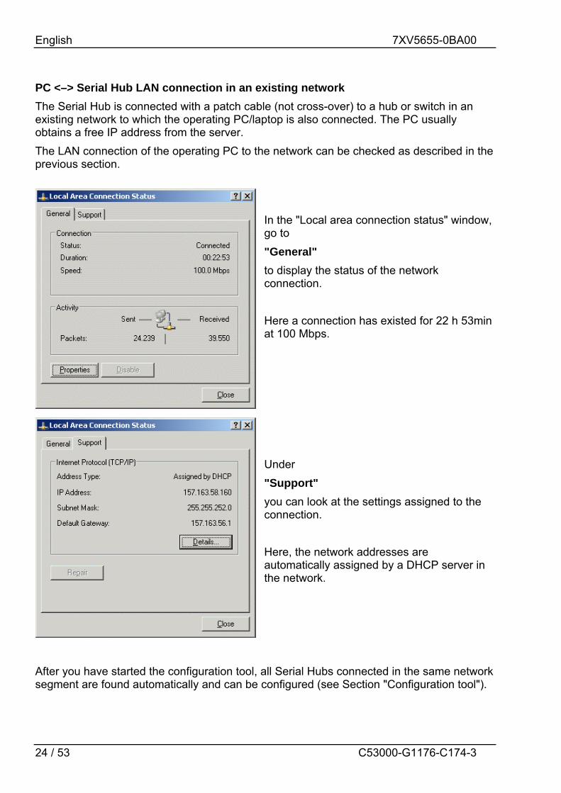
PC <–> Serial Hub LAN connection in an existing network The Serial Hub is connected with a patch cable (not cross-over) to a hub or switch in an existing network to which the operating PC/laptop is also connected. The PC usually obtains a free IP address from the server. The LAN connection of the operating PC to the network can be checked as described in the previous section.
In the "Local area connection status" window, go to "General" to display the status of the network connection. Here a connection has existed for 22 h 53min at 100 Mbps. Under "Support" you can look at the settings assigned to the connection. Here, the network addresses are automatically assigned by a DHCP server in the network.
After you have started the configuration tool, all Serial Hubs connected in the same network segment are found automatically and can be configured (see Section "Configuration tool").

English 7XV5655-0BA00
25 / 53 C53000-G1176-C174-3
Using "HyperTerminal" via the Serial Interface of a PC This terminal program is supplied as a standard part of the operating system, e.g. WINDOWS® 2000 and WINDOWS® XP. Start HyperTerminal under: "Start Programs Accessories Communications HyperTerminal"
Enter a name for the new connection, e.g. 9600 8N1. The connection can be saved on exiting. Assign a PC interface to the connection, e.g. COM1.
For a new Serial Hub, select the settings 9600 bits per second, 8 data bits, none for parity, 1 stop bit and none for flow control Continue with OK
Note: The Serial Hub data traffic can only be observed via the serial interface in the currently set baudrate and data format. If these settings were changed, the connection settings in HyperTerminal would have to be adjusted. It is advisable to note down these settings to avoid any problems accessing the Serial Hub later.

English 7XV5655-0BA00
26 / 53 C53000-G1176-C174-3
If the Serial Hub is connected to the PC, it is possible to listen in to the data traffic on the RS232 interface using HyperTerminal. This is useful, for example, when troubleshooting or to monitor the function of the Serial Hub after pressing the INIT button.
Calling the Program from the Desktop In practice, it as proven useful to set up a "link" on the desktop or on the quick launch bar for frequently used programs. To set devices with different baudrates or data formats via the serial interface (e.g. Serial Hub), it is possible to place various HyperTerminal connections and set up links to them on the desktop.

English 7XV5655-0BA00
27 / 53 C53000-G1176-C174-3
The Configuration Tool
Configuring the Serial Hub with the Configuration Tool The configuration tool provides a way of making "basic settings" such as Serial Hub name, IP address and baudrate of the Serial Hub. For this purpose, the configuration tool is started and finds all Serial Hubs in the same network segment which it then lists in a table.
Overview Window The configuration program finds all devices in its own network segment, even those without a valid IP address.
Clicking on the column header in the overview, e.g. "IP address", sorts the devices in ascending or descending order of the items in that column.
Items in the Overview Window: Name Serial Hub name for better identification by means of a self-
explanatory text.
IP Address Current IP address
Subnet Mask Current Subnet Mask
Gateway Current Gateway MAC Worldwide unique MAC address

English 7XV5655-0BA00
28 / 53 C53000-G1176-C174-3
Device Type Device Type
Version Current firmware version
Info Currently configured COM port (not available for Serial Hubs)
In Use If this entry is "true", the device is in connection mode and it is not possible to make changes to parameterisation.
Ping OK If this entry is "False", the device will no longer be found. It is not connected, deactivated, or is behind a router that is blocking the UDP port 3497.
in local Net If this entry is "False", the device is not in the local network segment. If the device is installed behind a router, the IP address cannot be changed. This prevents the device from being accessed unintentionally.
Password If this entry is "True", the device is password-protected and the password must be entered before configuration (by right-clicking "login"). If the password is forgotten, the device must be submitted again (see last page).
Logged in If this entry is "False", the password has to be entered before configuration (by right-clicking "login").
CPU-ID Internal device ID (not relevant for users)
General Settings A unique IP address must first be assigned to each device. When the Serial Hub is delivered, no valid IP address has been set yet (default: 10.10.5.1). If the Serial Hub is integrated into a DHCP network, i.e. the available IP addresses are assigned automatically, the network administrator on the DHCP server must reserve a fixed IP address for the Serial Hub. Right-clicking the device entry in the overview window displays a dialog box in which further actions can be performed.

English 7XV5655-0BA00
29 / 53 C53000-G1176-C174-3
Set IP Address
Enter a fixed IP address, Subnet-Mask and Default-Gateway for operation of the Serial Hubs in a network. If the allocated IP-address and the Subnet-Mask are not compatible the properties can not be changed any more. In such an event please change the settings.
Set Name
Enter the name of the Serial Hub, e.g. "Substation east" for a better clarity in the table.
Password
Before you can assign or change a password, you must first enter the old password, then the new password twice.
If the password has been forgotten, the device must be sent in.
(For address, see last page of this manual)

English 7XV5655-0BA00
30 / 53 C53000-G1176-C174-3
Upload Firmware
Look for the new firmware version and import with "Open" or by double-clicking. The firmware update resets the Serial Hub to its factory settings (default values). Passwords are not reset. If the message: "Can’t upload Firmware. See Logging" appears during a firmware update, please repeat the upload until the message: "device is up again" appears. You will find new firmware and manuals under : www.siprotec.com / Accessories / 7XV5655
Delete Currently marked entry is deleted.
Add Device Manually
If the Serial Hub is connected behind a router, it is not found automatically but must be added manually ("Add Device manually"). This is done by entering its IP address in the field. If the device can be accessed at this address, it is put in the list. Note: If the device is installed behind a router, the IP address cannot be changed. This prevents the device from being accessed unintentionally.

English 7XV5655-0BA00
31 / 53 C53000-G1176-C174-3
View Event Log
View current logfile (internal trace)
Properties Type-specific configuration user interface For more information, see the relevant sections.
Note regarding storage of the Properties “IP-Address“, “Name“ and “Password“ are saved in the Serial Hub. The virtual ”COM-Port“ and the associated ”IP-Address“ are saved in each operator PC. All other settings are saved in the operator Pc. The Config Tool displays the settings of the operator PC and Serial Hub. Each time the COM-Ports is opened “all other settings” along with the “baud rate” and “data format” are transferred from the application to the Serial Hub. If more than one operator PC is used to access the same Serial Hub, then these settings must be applied on all these operator PCs. The virtual COM-Port for a particular Serial Hub may be different on different operator PCs. If the Serial Hub is “in use”, i.e. it is connected to an operator PC, it is barred for all other operator PCs and the allocated COM-port for this Serial Hub is not shown in the application. In this manner a data collision is avoided is such a “multi master system”.

English 7XV5655-0BA00
32 / 53 C53000-G1176-C174-3
Properties Double-clicking the device entry in the overview window displays a dialog box in which further settings can be made.
A detailed dialog box consisting of six setting tab cards opens:
TCP/IP Settings
"Info" displays the MAC address, IP address and the Device name
English 7XV5655-0BA00
33 / 53 C53000-G1176-C174-3
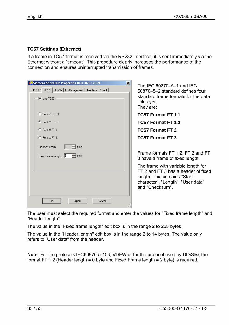
TC57 Settings (Ethernet) If a frame in TC57 format is received via the RS232 interface, it is sent immediately via the Ethernet without a "timeout". This procedure clearly increases the performance of the connection and ensures uninterrupted transmission of frames.
The user must select the required format and enter the values for "Fixed frame length" and "Header length". The value in the "Fixed frame length" edit box is in the range 2 to 255 bytes. The value in the "Header length" edit box is in the range 2 to 14 bytes. The value only refers to "User data" from the header. Note: For the protocols IEC60870-5-103, VDEW or for the protocol used by DIGSI®, the format FT 1.2 (Header length = 0 byte and Fixed Frame length = 2 byte) is required.
The IEC 60870–5–1 and IEC 60870–5–2 standard defines four standard frame formats for the data link layer. They are: TC57 Format FT 1.1 TC57 Format FT 1.2 TC57 Format FT 2 TC57 Format FT 3 Frame formats FT 1.2, FT 2 and FT 3 have a frame of fixed length. The frame with variable length for FT 2 and FT 3 has a header of fixed length. This contains "Start character", "Length", "User data" and "Checksum".
English 7XV5655-0BA00
34 / 53 C53000-G1176-C174-3
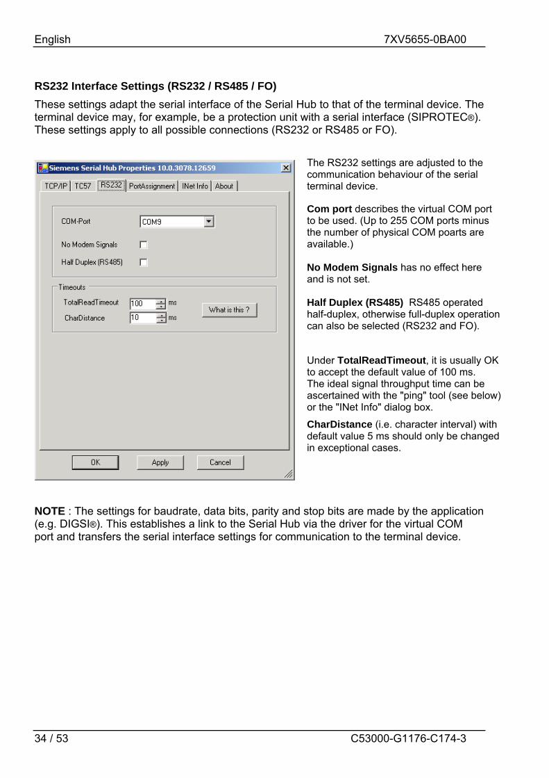
RS232 Interface Settings (RS232 / RS485 / FO) These settings adapt the serial interface of the Serial Hub to that of the terminal device. The terminal device may, for example, be a protection unit with a serial interface (SIPROTEC®). These settings apply to all possible connections (RS232 or RS485 or FO).
NOTE : The settings for baudrate, data bits, parity and stop bits are made by the application (e.g. DIGSI®). This establishes a link to the Serial Hub via the driver for the virtual COM port and transfers the serial interface settings for communication to the terminal device.
The RS232 settings are adjusted to the communication behaviour of the serial terminal device.
Com port describes the virtual COM port to be used. (Up to 255 COM ports minus the number of physical COM poarts are available.) No Modem Signals has no effect here and is not set. Half Duplex (RS485) RS485 operated half-duplex, otherwise full-duplex operation can also be selected (RS232 and FO).
Under TotalReadTimeout, it is usually OK to accept the default value of 100 ms. The ideal signal throughput time can be ascertained with the "ping" tool (see below) or the "INet Info" dialog box. CharDistance (i.e. character interval) with default value 5 ms should only be changed in exceptional cases.
English 7XV5655-0BA00
35 / 53 C53000-G1176-C174-3
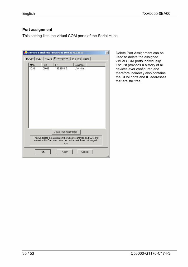
Port assignment This setting lists the virtual COM ports of the Serial Hubs.
Delete Port Assignment can be used to delete the assigned virtual COM ports individually. The list provides a history of all devices ever configured and therefore indirectly also contains the COM ports and IP addresses that are still free.

English 7XV5655-0BA00
36 / 53 C53000-G1176-C174-3
INet Info This window provides up-to-date network information.
The "Start" button transmits a ping to the Serial Hub to ascertain the throughput time of the telegrams in the network. Throughput time + 10ms = ideal "Total Timeout" here <10ms + 10ms = 20ms
Trace Route Ping

English 7XV5655-0BA00
37 / 53 C53000-G1176-C174-3
About This window provides information about the program version and the date of creation of this configuration tool.
You can also access the download area using an Internet browser at: www.siprotec.com
If the PC has Internet access, you can double-click the image for direct access to our Download Area. All up-to-date documents, drivers and updates for our products are available there.

English 7XV5655-0BA00
38 / 53 C53000-G1176-C174-3
Optimising Data Transfer Great emphasis has been placed on compatibility in the design of this device. Due to the Ethernet, there are, however, some minor restrictions. Data is not transmitted in bytes to the network, but Ethernet blocks are formed. This might result in minor delays. Block formation function does not directly affect the application but might help to reduce the network load. Some fine tuning might be necessary for time-critical applications as well. This involves the two timeout parameters ("Total Read Timeout", "Character Distance").
Block Formation for Serial Data before Transmission into the Ethernet After the first byte has been received, "Total Read Time" starts. After the time expires, all characters received so far are relayed to the Ethernet. The default value is 50 ms. "Character Distance" is the maximum interval between two received characters. If this is exceeded, all characters received so far are transmitted into the Ethernet. The default value is 5 ms.
Total read timeout Total read timeout
Character timeout
Transmissionto PC
Transmissionto PC
Transmissionto PC
No transmission. Gap is too small.
Transmission because "Total Timeout" has
expired
Transmission because the gap between the characters is larger than "Char Timeout"
Transmission because the gap between the characters is larger than "Char Timeout"

English 7XV5655-0BA00
39 / 53 C53000-G1176-C174-3
Protocol Code TC57 for Transmission into the Ethernet This procedure considerably enhances transmission rates when TC57 compatible protocols are transmitted. If the RS232 interface detects a protocol packet of this type, it is transmitted as a block via the Ethernet immediately without waiting for a timeout to elapse. The Serial Hub can be adapted to various standards. The IEC 60870–5–1 and IEC 60870–5–2 standards define four standard frame formats for the data link layer: 0 = Format FT 1.1 2 = Format FT 2 1 = Format FT 1.2 3 = Format FT 3 Frame formats FT 1.2, FT 2 and FT 3 have a frame of fixed length. The frame with variable length for FT 2 and FT 3 has a header of fixed length. This contains "Start character", "Length", "User data" and "Checksum". The user must select the required format and enter the values for "Fixed frame length" and "Header length".
Protocol code for IEC 60870-5, VDEW and DIGSI® The IEC 60870–5–102 / 103, VDEW, DIGSI® V3 and DIGSI® 4 protocols are identical to or so similar to this specification that the protocol code of this Serial Hub can be used. This is done by activating the protocol code, selecting format FT1.2 and setting a fixed frame length of 2 bytes.

English 7XV5655-0BA00
40 / 53 C53000-G1176-C174-3
Selecting a Password-Protected Serial Hub The password is for activation of the configuration mode with the configuration tool and for establishing the link. If no password is assigned, this must be entered in the configuration tool under 'Password required'=false.
Entering a Password To enter a password, call 'Change Password' from the configuration tool and enter the password under 'New Password' and then under 'Retype New Password' before pressing "Enter". The password has up to 8 digits. To be able to access a password-protected Serial Hub later from the computer from which the application will be started, the password must be entered on this computer.
Entering the log-in To access parameter entry from the configuration tool, an assigned password must be entered in 'Login'.
Entering an Incorrect Password If you enter the wrong password, the message "Invalid Password" is displayed.
Password transfer by the application If a password has been assigned, it must be passed on from the application. For this purpose, the Serial Hub must also be configured once from the application computer. This is done using the configuration tool.

English 7XV5655-0BA00
41 / 53 C53000-G1176-C174-3
Pin Assignment The cables for RS232 and RS485 are connected to the same port and selected using the DIP switches.
RS232 Interface SERIAL PORT 9-pin SubD connector
Pin Direction Definition
1 Screen
2 INPUT RXD Receive Data
3 OUTPUT TXD Transmit Data
4 not connected
5 GND Ground (ext)
6 not connected
7 not connected
8 Do not assign !
9 not connected
RS485 Interface SERIAL PORT 9-pin SubD connector
Pin Direction Definition
1 Screen
2 Do not assign !
3 INPUT/ OUTPUT RS485 Data-A
4 not connected
5 GND Ground (ext)
6 not connected
7 not connected
8 INPUT/ OUTPUT RS485 Data-B
9 not connected

English 7XV5655-0BA00
42 / 53 C53000-G1176-C174-3
Ethernet Interface Ethernet connector RJ 45
Pin Name Definition 1 TX+ Transmit Data+ 2 TX- Transmit Data- 3 RX+ Receive Data+ 4 n/c not connected 5 n/c not connected 6 RX- Receive Data- 7 n/c not connected 8 n/c not connected
Ethernet RJ45 connector
Auxiliary Voltage and Earth Connection 3-way terminal block
Vaux
Screen L- L+
Pin Name Definition 1 L+ Vaux+ 2 L- Vaux- 3 Earth Protective Earth
The device features internal reverse polarity protection for Vaux.
DR Contact 2-way terminal block
DR
Pin Name Definition 1 DR Isol. DR 2 DR-NC Isol. DR-NC

English 7XV5655-0BA00
43 / 53 C53000-G1176-C174-3
Connecting Cable RS232 connection options: 1) PC/laptop to the protection unit plug in serial DIGSI cable directly 2) Serial Hub to SIPROTEC 4 or plug in serial DIGSI cable via gender 7XV5300, 7XV5450, 7XV5550, 7XV5652 changer (male-male) to Serial Hub Serial DIGSI Cable
RxD
GND
TxD
4
5
Notebook / PC9-way male
3
5
Housing Housing
7XV5100-4/BBLength=3m
Notebook / PC 9-way female
2
32
6 7 8
78
For further cables and adapters, see: www.siprotec.com Accessories Common information Handbuch_Zubehoer (German only) Serial RS485 Connecting Cable
A
B
From serial model SUB-D connector 9-way male
83
SIPROTECSUB-D connector 9-way male
L=0.2 m 8
3
Further devices or bus terminationSUB-D connector9-way female
3
8
Housing
A
B
Housing
Housing
L=1/3/5/10 m
7XV5103-0AAxx
xx= length
For further RS485 cables and adapters, see: www.siprotec.com Accessories 7XV5103 Catalog sheet

English 7XV5655-0BA00
44 / 53 C53000-G1176-C174-3
Technical Data
Auxiliary voltage Power input Line-side fuse Alarm relay (DR) Connection Switching current (continuous) Switching voltage Switching capacity 3-way terminal
Minimum cross-section of the wires for auxiliary voltage and earth (ground) Nominal conductor cross-section Tightening torque Stripping length:
24 V – 250 V DC +/-20 % 60 V – 230 V AC +/-20 % , 45-65 Hz, 2.5 W DC 14 VA AC T 2A/250 V AC and 250 V DC acc. to IEC 60127 Relays, 1 NC isolated 2-way screw terminal, 1A 250V AC and DC 20 W / 20 VA 1.5 mm2 2.5 mm² , rigid conductor or with wire end ferrule 0.5 Nm up to 8 mm
FO connection Connection method Wavelength Fibre Type Baud rate Protocol Laser class Transmit power in dBm , peak (type), NA = 0.275 Max. optical power for high level Min. optical power for low level Optical power budget NA = 0.275 Range
ST connector receiver and transmitter 820 nm Multimode fibre, 62.5/125 µm 2400 up to max. 115200 baud full-duplex 1 acc. to EN60825-1/-2 using glass fibre 62.5/125 µm -12.0 (fibre type 62.5/125 µm) Max. -40 dBm peak Min.: -24 dBm peak Min. 8 dB (62.5/125 µm) Max. 2 Km (attenuation 3 dB / Km 62.5 µm) Max. 2 m with plastic fibre
Ethernet interface Connection TCP/IP
10BaseT (10/100 Mbits) RJ45, screened, 8-way UDP Port 3497 (User Datagram Protocol) ICMP (Internet Control Message Protocol) ARP (Address Resolution Protocol)

English 7XV5655-0BA00
45 / 53 C53000-G1176-C174-3
RS232 and RS485 Connection type Pin assignment Cable length RS232 Baud rate
9-way SubD connector, 4/40 UNC screw connection See Pin Assignment Max. 10 m / 3280 feet 2400 to 115200 baud, Rxd, Txd Parity : None, Even, Odd, Mark, Space Data : 7 or 8 bits Stop : 1 or 2 bits RS232 : full-duplex , RS485 : half-duplex
DIP switches
RS232/485 switchover Idle state FO ON/OFF RS485 termination
LED displays
DR (GN): Alarm (Vaux power o.k. and reset o.k.) COM-TxD (GN) : Transmit - RS232 or RS485 or FO COM-TxD (YE) : Receive - RS232 or RS485 or FO System (GN) : Connection to the PC via RS232 detected LAN-TxD (GN) : Transmit Ethernet LAN-TxD (YE) : Receive - Ethernet LAN (GN) : Connection to the Ethernet network Error (RD) : hub error on RS232/Reset
Firmware Driver
Updatable Setup & configuration tool for WINDOWS® NT4 / 2000 / XP Note : To operate this Serial Hub, Windows XP Home Edition is sufficient but for DIGSI, XP Professional is required.
Mechanical design Housing Dimensions Weight: Degree of protection acc. to EN60529 Protection class
Plastic See Dimension Drawings Approx. 180 g IP20 (housing and terminals) I Protective Earth
Safety Acc. to DIN EN61010 Part 1 Overvoltage category Pollution degree Fire resistance class (acc. to UL94)
III 2 V0

English 7XV5655-0BA00
46 / 53 C53000-G1176-C174-3
Standards: IEC 60255 (product standard)
IEEE Std C37.90.0/.1/ VDE 0435 For more standards, see each function
Insulation tests Standards:
IEC 60255-5 and IEC 60870-2-1
Voltage test (100% test) all circuits except auxiliary voltage and communication interfaces
2.5 kV (rms), 50 Hz
Voltage test (100% test) on auxiliary voltage 3.5 KV DC Voltage test (100% test) only locked communication interfaces
500 V (rms), 50 Hz
Surge withstand capability test (type test) all circuits except communication interfaces, class III
5 kV (peak value); 1.2 / 50 µs; 0.5 J; 3pos./neg. surges at 5s intervals
Warning The 7XV5655-0BA00 is specifically intended for installation in a switchgear cubicle or distribution box. After installation, the entire area around the terminals must be covered. Only then is the device sufficiently protected against impermissible contact with live parts.
EMC tests for immunity (type tests)
Standards:
IEC 60255-6 and -22 (product standards) EN61000-6-2 (generic standard) VDE 0435 part 301DIN VDE 0435-110
High Frequency Test IEC 60255-22-1, Class III and VDE 0435 Part 303, Class III
2.5 KV (peak); 1 MHz;15 = ז ms; 400 surges per s; test duration 2s; Ri = 200 Ω
Electrostatic Discharge IEC 60255-22-2, Class III
8 KV contact discharge; 15 KV air discharge pos./neg. polarity, 150 pF; Ri = 330 Ù
Irradiation with RF field, frequency sweep IEC60255-22-3, Class III IEC61000-4-3, Class III
10 V/m, 80 MHz to 1000 MHz: 80% AM, 1 kHz
Irradiation with RF field, single frequencies IEC60255-22-3, IEC61000-4-3
- amplitude-modulated - pulse-modulated
Class III: 10 V/m 80, 160, 450, 900 MHz; 80 % AM 1kHz; duty cycle > 10 s 900 MHz; 50% PM, repetition frequency 200 Hz
Fast transients / bursts IEC 60255-22-4 and IEC61000-4-4 Class IV
4 kV; 5/50 ns; 5 kHz; burst length = 15 ms; Repeat rate 300 ms; pos./neg. polarity; test duration 1 min.; Ri = 50 Ù
High energy surge voltages (SURGE) EN61000-4-5 insulation class 3 - Auxiliary voltages
Pulse: 1.2/50 µs common mode; 2 KV; 12 Ω; 9 µF differential mode : 1 kV; 2 Ω; 18 µF

English 7XV5655-0BA00
47 / 53 C53000-G1176-C174-3
- Relay output common mode; 2 KV; 42 Ù; 0.5 µF differential mode : 1 KV; 42 Ω; 0.5 µF
Conducted RF, amplitude-modulated IEC61000-4-6, Class III
10 V; 150 KHz – 80 MHz; 80 % AM, 1 KHz
Magnetic field with power frequency EN61000-4-8 IEC60255-6
0.5 mT; 50 Hz Class IV: 30 A/m continuous; 300 A/m for 3s; 50Hz
Oscillatory Surge Withstand Capability IEEE Std C37.90.1
2.5 KV (peak); 1 MHz;15 = ז µs; 400 surges per s; test duration 2s; Ri = 200 Ω
Fast transient surge withstand capability IEEE Std C37.90.1
4 kV; 5/50 ns; 5 kHz; burst length = 15 ms; Repeat rate 300 ms; pos./neg. polarity; test duration 1 min.; Ri = 50 Ù
Damped oscillations IEC 60694, IEC 61000-4-12
2.5 kV (peak value), polarity alternating 100 kHz, 1 MHz, Ri = 200 Ω
EMC tests for emission (type tests)
Standard: EN 61000-6-4/3 (generic standard) Radio interference voltage on lines Auxiliary voltage only IEC CISPR 22
150 kHz to 30 MHz Limit class B
Interference field strength IEC CISPR 11
30 to 1000 MHz Limit value class A
Mechanical tests, vibration and shock stress - stationary use
Vibration IEC 60255-21-1, Class 2 IEC 60068-2-6
Sinusoidal, 10 to 58 Hz : 0.075 mm ampl. 58 to 150 Hz : 1.0 g accel. 20 cycles in 3 orthogonal axes
Shock IEC 60255-21-2, Class 1
Semi-sinusoidal, 5 g accel., 11 ms duration 3 shocks each in both directions of the 3 axes
Seismic vibration IEC 60255-21-3, Class 1 IEC 60068-3-3
Sinusoidal, 1 to 8 Hz : 4 mm ampl. horizontal 1 to 8 Hz : 2 mm ampl. vertical 8 to 35 Hz : 1 g accel., horizontal 8 to 35 Hz : 0.5 g accel., vertical 1 cycle in 3 orthogonal axes

English 7XV5655-0BA00
48 / 53 C53000-G1176-C174-3
Mechanical tests, vibration and shock stress - during transport
Vibration IEC 60255-21-1, Class 2 IEC 60068-2-6
Sinusoidal, 5 to 8 Hz : 7.5 mm ampl. 8 to 150 Hz : 2 g accel., 20 cycles in 3 orthogonal axes
Shock IEC 60255-21-2, Class 1 IEC 60068-2-27
Semi-sinusoidal, 15 g accel., 11 ms duration 3 shocks each in both directions of the 3 axes
Shock IEC 60255-21-2, Class 1 IEC 60068-2-27
Semi-sinusoidal, 10 g accel., 16 ms duration 1000 shocks each in both directions of the 3 axes
Climatic tests
Recommended operating temperature Limit temp. during operation Limit temp. during storage Limit temp. during transport Humidity Maximum relative humidity Installation altitude Maximum height above sea level
0 °C to 55 °C -5 °C to +70 °C -25 °C to +55 °C (factory packing) -25 °C to +70 °C (factory packing) 80 % at temperatures up to 31 °C, decreasing linearly down to 50 % at 40 °C 2,000 m
All devices shall be installed so that they are not exposed to direct sunlight, nor subject to great fluctuations in temperature that may cause condensation.

English 7XV5655-0BA00
49 / 53 C53000-G1176-C174-3
Dimensions

English 7XV5655-0BA00
50 / 53 C53000-G1176-C174-3
Ordering Information Name Order No.
Serial Hub 7 X V 5 6 5 5 - 0 B A 0 010BaseT connection 10/100 Mbits, RJ45 connector Serial RS232/485 interface 9-way Sub D connector Gender changer (male-male) FO interface, ST connection DIN rail mounted device for 35mm rail Aux. voltage 24-250 VDC / 60-230 VAC

SIEMENS AKTIENGESELLSCHAFT
Änderungen vorbehalten Subject to change without prior notice
Weitergabe sowie Vervielfältigung dieser Unterlage, Verwertung und Mitteilung ihres Inhalts nicht gestattet, soweit nicht ausdrücklich zugestanden. Zuwiderhandlungen verpflichten zu Schadenersatz. Alle Rechte für den Fall der Patenterteilung oder GM–Eintragung vorbehalten. The reproduction, transmission or use of this document or its contents is not permitted without express written authority. Offenders will be liable for damages. All rights, including rights created by patent grant or registration of a utility model or design, are reserved. Release 3.00.00

Hinweise und Fragen zu diesem Produkt richten Sie bitte an folgende Adresse:
Defekte Geräte senden Sie bitte an folgende Adresse:
Siemens AG Power Transmission and Distribution Energy Automation PTD Customer Support Center Humboldtstrasse 59 D-90459 Nürnberg Telefon : +49 +180 / 524 – 7000 Telefax : +49 +180 / 524 – 2471 Email : [email protected]
Siemens AG Power Transmission and Distribution Energy Automation PTD EA P Rückwarenabteilung Wernerwerkdamm 5 D-13629 Berlin
Weitere Informationen zu unseren Produkten finden Sie in unserer Download Area im Internet:
www.SIPROTEC.de
If you have any notes or questions on this product please contact :
Please send defective devices to :
Siemens AG Power Transmission and Distribution Energy Automation PTD Customer Support Center Humboldtstrasse 59 D-90459 Nürnberg Phone : +49 +180 / 524 – 7000 Fax : +49 +180 / 524 – 2471 E-mail : [email protected]
Siemens AG Power Transmission and Distribution Energy Automation PTD EA P ACC2 Returned Goods Customer Service Wernerwerkdamm 5 D-13629 Berlin
Further information regarding our products is to be found in our download area in the Internet:
www.SIPROTEC.com

SIEMENS AKTIENGESELLSCHAFT