7sr11 & 7sr12 installation guide - siemens power...
TRANSCRIPT
7SR11 & 7SR12 Installation Guide
The copyright and other intellectual property rights in this document, and in any model or article produced from it (and including any registered or unregistered design rights) are the property of Siemens Protection Devices Limited. No part of this document shall be reproduced or modified or stored in another form, in any data retrieval system, without the permission of Siemens Protection Devices Limited, nor shall any model or article be reproduced from this document unless Siemens Protection Devices Limited consent. While the information and guidance given in this document is believed to be correct, no liability shall be accepted for any loss or damage caused by any error or omission, whether such error or omission is the result of negligence or any other cause. Any and all such liability is disclaimed. ©2012 Siemens Protection Devices Limited
7SR11 and 7SR12 Installation Guide Document Release History This document is issue 2012/01. The list of revisions up to and including this issue is:
2012/01 Software Maintenance
2011/06 Software Maintenance
2011/06 Added CT and VT connection information
2010/04 Amendments following PLM review
2010/02 Document reformat due to rebrand
2009/09 Revised format
2009/04 First issue
Software Revision History
2012/01 7SR11 2436H80003 R2a-2a
7SR12 2436H80004 R2a-2a
Software Maintenance
2011/06 7SR11 2436H80003 R2-2
7SR12 2436H80004 R2-2
Software Maintenance
2009/04 2436H80003R1g-1c 7SR11
3436H80004R1g-1c 7SR12
First Release
7SR11 & 7SR12 Installation Guide
Contents
Section 1: Installation............................................................................................................................................... 3 1.1 Packaging ............................................................................................................................................... 3 1.2 Unpacking, Storage and Handling .......................................................................................................... 3 1.3 Recommended Mounting Position .......................................................................................................... 3 1.4 Wiring...................................................................................................................................................... 3 1.5 Earthing................................................................................................................................................... 3 1.6 Ancillary Equipment ................................................................................................................................ 4 1.7 Disposal .................................................................................................................................................. 4
Section 2: Equipment Operating Conditions ............................................................................................................ 5 2.1 Current Transformer Circuits................................................................................................................... 5 2.2 External Resistors................................................................................................................................... 5 2.3 Front Cover ............................................................................................................................................. 5
Section 3: Dimensions and Panel Fixings................................................................................................................ 6 3.1 Relay Dimensions and Weight ................................................................................................................ 6 3.2 Fixings..................................................................................................................................................... 7
3.2.1 Crimps....................................................................................................................................... 7 3.2.2 Panel Fixings ............................................................................................................................ 7
Section 4: Rear Terminal Drawings ......................................................................................................................... 8 4.1 E4 Case .................................................................................................................................................. 8
Section 5: Connection/Wiring/Diagrams ................................................................................................................ 10 5.1 Wiring Diagram: 7SR1101 EF Relay with 3BI & 5BO............................................................................ 10 5.2 Wiring Diagram: 7SR1102 OC/EF Relay with 3BI & 5BO ..................................................................... 11 5.3 Wiring Diagram: 7SR1103 OC/EF Relay with 6 BI & 8BO .................................................................... 12 5.4 Wiring Diagram: 7SR1204 Directional EF Relay with 3BI & 5BO.......................................................... 13 5.5 Wiring Diagram: 7SR1205 Directional OC/EF Relay with 3BI & 5BO ................................................... 14 5.6 Wiring Diagram: 7SR1206 Directional OC/EF Relay with 6BI & 8BO ................................................... 15 5.7 Current Transformer Configurations...................................................................................................... 16 5.8 Voltage Transformer Configurations ..................................................................................................... 21
Section 6: Data Comms Connections .................................................................................................................... 22 6.1 RS485 Connection................................................................................................................................ 22
List of Figures Figure 3.1-1 Overall Dimensions and Panel Drilling for Size E4 Epsilon Case...................................................... 6 Figure 4.1-1 E4 Case viewed from rear ................................................................................................................. 8 Figure 4.1-2 E4 Case Terminal Arrangement viewed from rear ............................................................................ 9 Figure 5.1-1 7SR1101 Connection Diagram........................................................................................................ 10 Figure 5.2-1 7SR1102 Connection Diagram........................................................................................................ 11 Figure 5.3-1 7SR1103 Connection Diagram........................................................................................................ 12 Figure 5.4-1 7SR1204 Connection Diagram........................................................................................................ 13 Figure 5.5-1 7SR1205 Connection Diagram........................................................................................................ 14 Figure 5.6-1 7SR1206 Connection Diagram ......................................................................................................... 15 Figure 6.1-1 RS485 Data Comms Connections Between Relays........................................................................ 22
©2012 Siemens Protection Devices Limited Chapter 5 Page 2 of 22
7SR11 & 7SR12 Installation Guide
Section 1: Installation
1.1 Packaging Relays are supplied in packaging designed to mechanically protect them while in both transit and storage.
This packaging should be recycled where systems exist, or disposed of in a manner which does not provide a threat to health or the environment. All laws and regulations specific to the country of disposal should be adhered to.
1.2 Unpacking, Storage and Handling On receipt remove the relay from the container in which it was received and inspect it for obvious damage. It is recommended that the relay not be removed from its case.
If damage has been sustained a claim should be immediately be made against the carrier, also inform Siemens Protection Devices Limited, and the nearest Siemens agent.
When not required for immediate use, Relays should be stored in their original packaging. The place of storage should be dry and free from dust. It should also not exceed the storage temperature and humidity limits of the Relay; given in the Performance Specification of this manual.
The relay contains static sensitive devices, which are susceptible to damage due to static discharge. The relay’s electronic circuits are protected from damage by static discharge when the relay is housed in its case.
There can be no requirement to disassemble any relay, since there are no user serviceable parts in the relay. If any modules have been tampered with, then the guarantee will be invalidated. Siemens Protection Devices Limited reserves the right to charge for any subsequent repairs.
1.3 Recommended Mounting Position The relay uses a liquid crystal display (LCD) for programming and operation. The LCD has a vertical viewing angle of ± 30˚ and is back–lit. However, the best viewing position is at eye level, and this is particularly important given its control features.
The relay should be mounted on the circuit breaker (or protection panel) to allow the operator the best access to the relay functions
1.4 Wiring The product should be wired according to the scheme requirements, with reference to the appropriate wiring diagram.
1.5 Earthing Terminal 28 of the PSU (Power Supply Unit) should be solidly earthed by a direct connection to the panel earth. The Relay case earth stud connection should be connected to terminal 28 of the PSU.
It is normal practice to additionally 'daisy chain' together the case (safety) earths of all the Relays installed in a panel to prevent earth current loops posing a risk to personnel.
©2012 Siemens Protection Devices Limited Chapter 5 Page 3 of 22
7SR11 & 7SR12 Installation Guide
1.6 Ancillary Equipment The relay can be interrogated locally or remotely. For local interrogation a portable PC with suitable version of MS Windows (2000 SP4 or XP SP2)and Reydisp Evolution™ s/w (Latest Version available 32 bit) using USB port situated on front of the relay.
1.7 Disposal The Relay should be disposed of in a manner which does not provide a threat to health or the environment. All laws and regulations specific to the country of disposal should be adhered to. The relays and protection systems manufactured under the Reyrolle brand currently do not come within the scope of either the European WEEE or RoHS directives as they are equipment making up a fixed installation.
©2012 Siemens Protection Devices Limited Chapter 5 Page 4 of 22
7SR11 & 7SR12 Installation Guide
Section 2: Equipment Operating Conditions
2.1 Current Transformer Circuits The secondary circuit of a live CT must not be open circuited. Non-observance of this precaution can result in injury to personnel or damage to equipment.
!
2.2 External Resistors Where external resistors are connected to the relay circuitry, these may present a danger of electric shock or burns, if touched. !
2.3 Front Cover The front cover provides additional securing of the relay element within the case. The relay cover should be in place during normal operating conditions.
!
©2012 Siemens Protection Devices Limited Chapter 5 Page 5 of 22

7SR11 & 7SR12 Installation Guide
Section 3: Dimensions and Panel Fixings
3.1 Relay Dimensions and Weight Relays are supplied in the modular size E4
The following drawing which is available from the website gives panel cut-out and mounting details.
Figure 3.1-1 Overall Dimensions and Panel Drilling for Size E4 Epsilon Case
Hardware Model Net Weight Kg 7SR1101 2.7 7SR1102 3.2 7SR1103 3.2 7SR1204 2.7 7SR1205 3.2 7SR1206 3.2
©2012 Siemens Protection Devices Limited Chapter 5 Page 6 of 22
7SR11 & 7SR12 Installation Guide
3.2 Fixings
3.2.1 Crimps Ring tongued crimps with 90˚ bend are recommended.
3.2.2 Panel Fixings Typical mounting screw kit per Relay
Consists of 4 off M4x10mm Screws
4 off M4 Nuts
4 off M4 Lock Washer
Typical rear terminal block fixing kit (1kit per terminal block fitted to relay) Consists of:
28 off M4, 8mm Screws
28 off M4 Lock Washer
©2012 Siemens Protection Devices Limited Chapter 5 Page 7 of 22
7SR11 & 7SR12 Installation Guide
Section 4: Rear Terminal Drawings
4.1 E4 Case
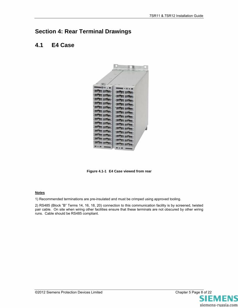
Figure 4.1-1 E4 Case viewed from rear
Notes
1) Recommended terminations are pre-insulated and must be crimped using approved tooling.
2) RS485 (Block ”B” Terms 14, 16, 18, 20) connection to this communication facility is by screened, twisted pair cable. On site when wiring other facilities ensure that these terminals are not obscured by other wiring runs. Cable should be RS485 compliant.
©2012 Siemens Protection Devices Limited Chapter 5 Page 8 of 22
7SR11 & 7SR12 Installation Guide
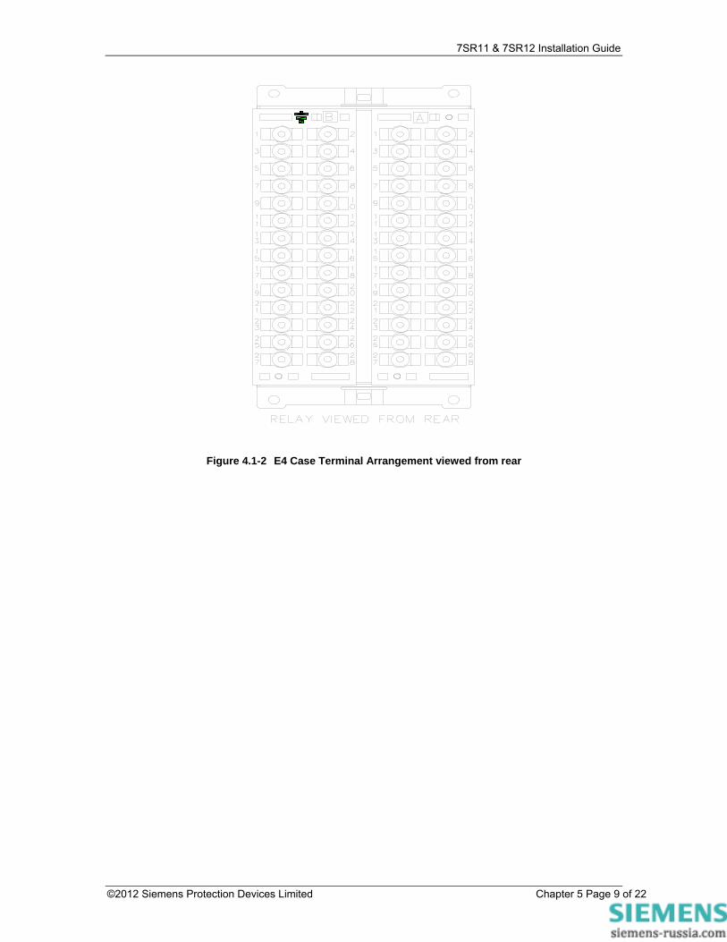
Figure 4.1-2 E4 Case Terminal Arrangement viewed from rear
©2012 Siemens Protection Devices Limited Chapter 5 Page 9 of 22

7SR11 & 7SR12 Installation Guide
Section 5: Connection/Wiring/Diagrams
5.1 Wiring Diagram: 7SR1101 EF Relay with 3BI & 5BO
BO 1
GND.
BI 1
A
GND
B
Term.
+ve
-ve
+ve
-ve
22
24
28
2
4
BI 2+ve
-ve
6
8
BI 3+ve
-ve
10
12
14
16
18
20
IL4
25
26
27
28
BO 2 6
5
4
1
2
3
BO 38
7
BO 410
9
BO 512
11
1A
5A
A
Analogue
B
PSU
1 2
27 28
1 2
27 28
A
B
Shows contacts internal to relay case assembly.Contacts close when the relay chassis is withdrawn from case
NOTES
BI = Binary InputBO = Binary Output
Rear ViewArrangement of terminals and modules
Figure 5.1-1 7SR1101 Connection Diagram
©2012 Siemens Protection Devices Limited Chapter 5 Page 10 of 22

7SR11 & 7SR12 Installation Guide
5.2 Wiring Diagram: 7SR1102 OC/EF Relay with 3BI & 5BO
BO 1
GND.
BI 1
A
RS
485GND
B
Term.
+ve
-ve
+ve
-ve
IL1
22
24
28
2
4
BI 2+ve
-ve
6
8
BI 3+ve
-ve
10
12
14
16
18
20
IL2
IL3
IL4
25
26
27
28
BO 2 6
5
4
1
2
3
BO 38
7
BO 410
9
BO 512
11
1A
5A
13
14
15
16
1A
5A
17
18
19
20
1A
5A
21
22
23
24
1A
5A
A
Analogue
B
PSU
1 2
27 28
1 2
27 28
A
B
Shows contacts internal to relay case assembly.Contacts close when the relay chassis is withdrawn from case
NOTES
BI = Binary InputBO = Binary Output
Rear ViewArrangement of terminals and modules
Figure 5.2-1 7SR1102 Connection Diagram
©2012 Siemens Protection Devices Limited Chapter 5 Page 11 of 22
7SR11 & 7SR12 Installation Guide
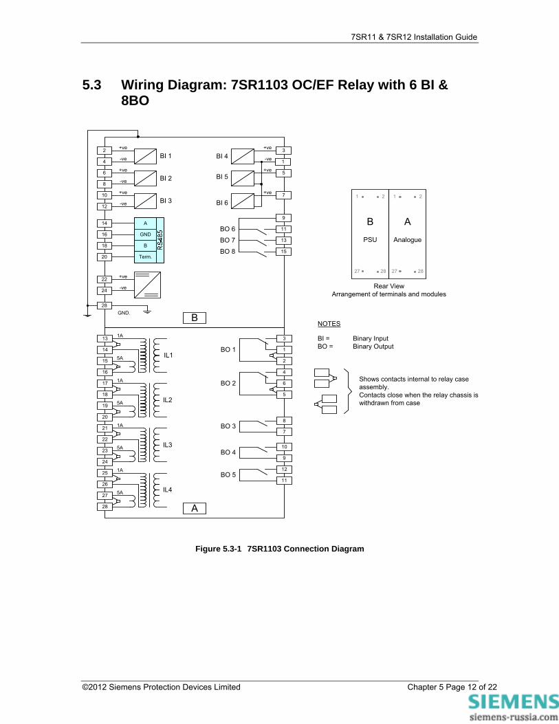
5.3 Wiring Diagram: 7SR1103 OC/EF Relay with 6 BI & 8BO
BO 1
GND.
BI 1
A
GND
B
Term.
+ve
-ve
+ve
-ve
IL1
22
24
28
2
4
BI 2+ve
-ve
6
8
BI 3+ve
-ve
10
12
14
16
18
20
IL2
IL3
IL4
25
26
27
28
BO 2 6
5
4
1
2
3
BO 38
7
BO 410
9
BO 512
11
1A
5A
13
14
15
16
1A
5A
17
18
19
20
1A
5A
21
22
23
24
1A
5A
A
Analogue
B
PSU
1 2
27 28
1 2
27 28
A
B
Shows contacts internal to relay case assembly.Contacts close when the relay chassis is withdrawn from case
NOTES
BI = Binary InputBO = Binary Output
Rear ViewArrangement of terminals and modules
BI 4+ve 3
BI 5+ve 5
BI 6+ve
-ve
7
1
BO 7
11
13
BO 8 15
9
BO 6
Figure 5.3-1 7SR1103 Connection Diagram
©2012 Siemens Protection Devices Limited Chapter 5 Page 12 of 22
7SR11 & 7SR12 Installation Guide
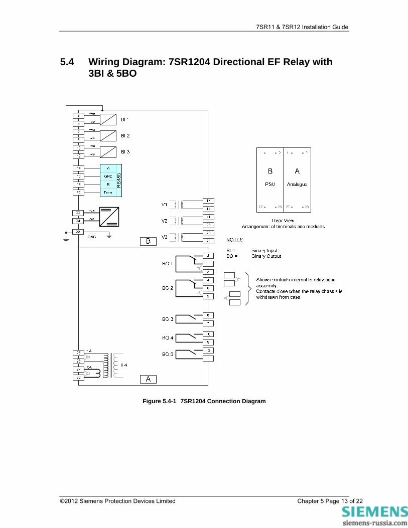
5.4 Wiring Diagram: 7SR1204 Directional EF Relay with 3BI & 5BO
Figure 5.4-1 7SR1204 Connection Diagram
©2012 Siemens Protection Devices Limited Chapter 5 Page 13 of 22
7SR11 & 7SR12 Installation Guide
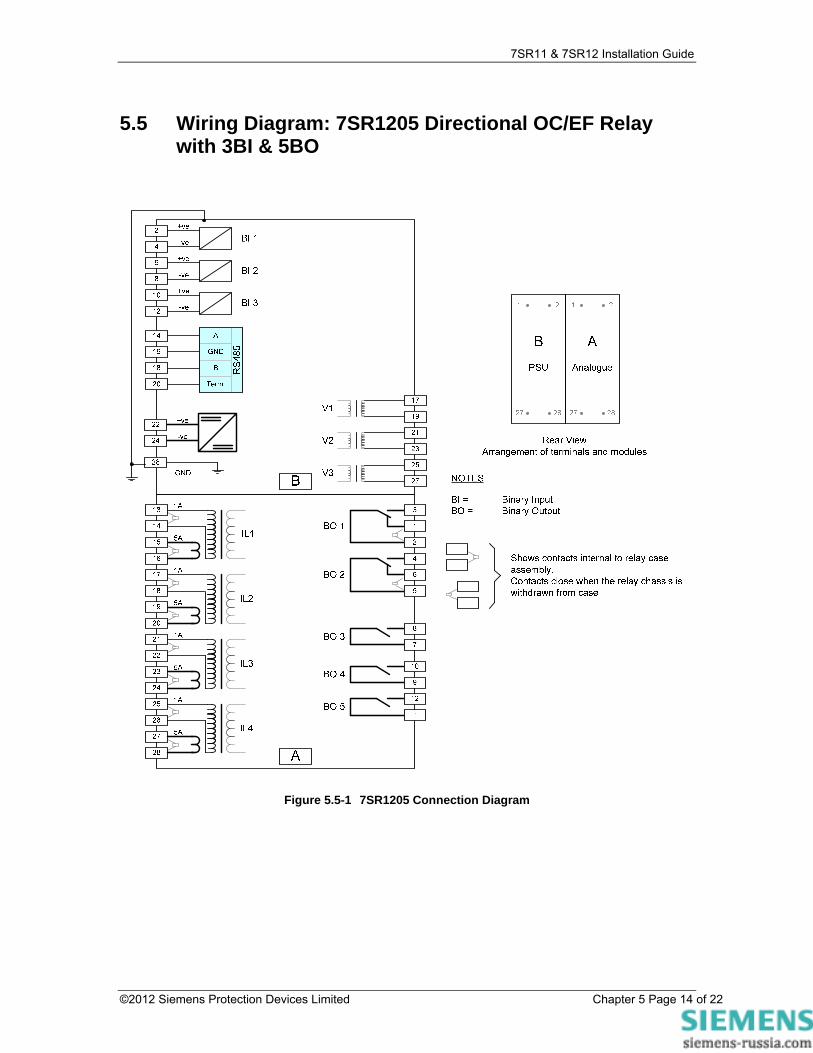
5.5 Wiring Diagram: 7SR1205 Directional OC/EF Relay with 3BI & 5BO
Figure 5.5-1 7SR1205 Connection Diagram
©2012 Siemens Protection Devices Limited Chapter 5 Page 14 of 22
7SR11 & 7SR12 Installation Guide
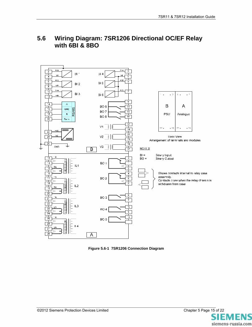
5.6 Wiring Diagram: 7SR1206 Directional OC/EF Relay with 6BI & 8BO
Figure 5.6-1 7SR1206 Connection Diagram
©2012 Siemens Protection Devices Limited Chapter 5 Page 15 of 22
7SR11 & 7SR12 Installation Guide
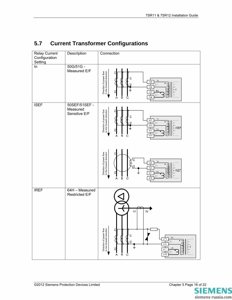
5.7 Current Transformer Configurations Relay Current Configuration Setting
Description Connection
In 50G/51G - Measured E/F
S2
S
1
P2
P1
Dire
ctio
n of
pow
er fl
owIn
the
forw
ard
dire
ctio
n
ISEF 50SEF/51SEF -
Measured Sensitive E/F
S2
S
1
P2
P1
Dire
ctio
n of
pow
er fl
owIn
the
forw
ard
dire
ctio
n
P2
P1
Dire
ctio
n of
pow
er fl
owIn
the
forw
ard
dire
ctio
n
S2
S
1
IREF 64H – Measured Restricted E/F
S2
S
1
P2
P1
Dire
ctio
n of
pow
er fl
owIn
the
forw
ard
dire
ctio
n
©2012 Siemens Protection Devices Limited Chapter 5 Page 16 of 22

7SR11 & 7SR12 Installation Guide
Ia, Ib, Ic In CT/VT CONFIG: Phase Current Input Phase CT Ratio
50/51 - Phase Overcurrent 50N/51N - Derived E/F Selects 1 or 5A CT ratio for primary meters
1A
5A Ig
A25
A26
A27
A28
Ic
Ib
1A
5A
A21
A22
A23
A24
1A
5A
A17
A18
A19
A20
Ia
1A
5A
A13
A14
A15
A16
A B C
S2
S1
P2
P1
Dire
ctio
n of
pow
er fl
owIn
the
forw
ard
dire
ctio
n
©2012 Siemens Protection Devices Limited Chapter 5 Page 17 of 22

7SR11 & 7SR12 Installation Guide
Ia, Ib, Ic In Ig CT/VT CONFIG: Phase Current Input Phase CT Ratio Earth Current Input Earth CT Ratio
50/51 - Phase Overcurrent 50N/51N - Derived E/F 50G/51G - Measured E/F Selects 1 or 5A CT ratio for primary meters
1A
5A Ig
A25
A26
A27
A28
Ic
Ib
1A
5A
A21
A22
A23
A24
1A
5A
A17
A18
A19
A20
Ia
1A
5A
A13
A14
A15
A16
A B C
S2
S1
P2
P1
Dire
ctio
n of
pow
er fl
owIn
the
forw
ard
dire
ctio
n
1A
5A Ig
A25
A26
A27
A28
Ic
Ib
1A
5A
A21
A22
A23
A24
1A
5A
A17
A18
A19
A20
Ia
1A
5A
A13
A14
A15
A16
A B C
©2012 Siemens Protection Devices Limited Chapter 5 Page 18 of 22
7SR11 & 7SR12 Installation Guide
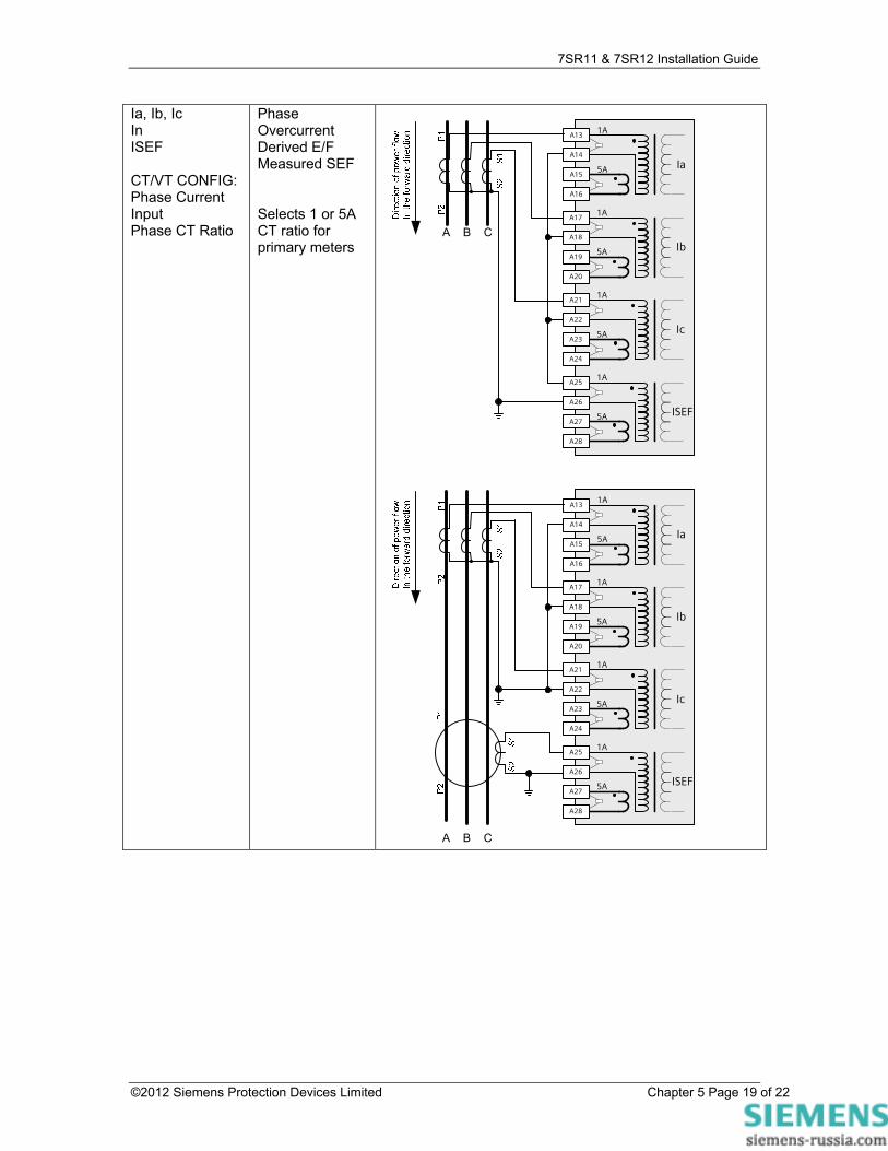
Ia, Ib, Ic In ISEF CT/VT CONFIG: Phase Current Input Phase CT Ratio
Phase Overcurrent Derived E/F Measured SEF Selects 1 or 5A CT ratio for primary meters
1A
5A ISEF
A25
A26
A27
A28
Ic
Ib
1A
5A
A21
A22
A23
A24
1A
5A
A17
A18
A19
A20
Ia
1A
5A
A13
A14
A15
A16
A B C
1A
5A ISEF
A25
A26
A27
A28
Ic
Ib
1A
5A
A21
A22
A23
A24
1A
5A
A17
A18
A19
A20
Ia
1A
5A
A13
A14
A15
A16
A B C
©2012 Siemens Protection Devices Limited Chapter 5 Page 19 of 22

7SR11 & 7SR12 Installation Guide
Ia, Ib, Ic In Ig CT/VT CONFIG: Phase Current Input Phase CT Ratio
Phase Overcurrent Derived E/F Measured Standby E/F Selects 1 or 5A CT ratio for primary meters
S2
S
1
P2
P1
Dire
ctio
n of
pow
er fl
owIn
the
forw
ard
dire
ctio
n
©2012 Siemens Protection Devices Limited Chapter 5 Page 20 of 22
7SR11 & 7SR12 Installation Guide
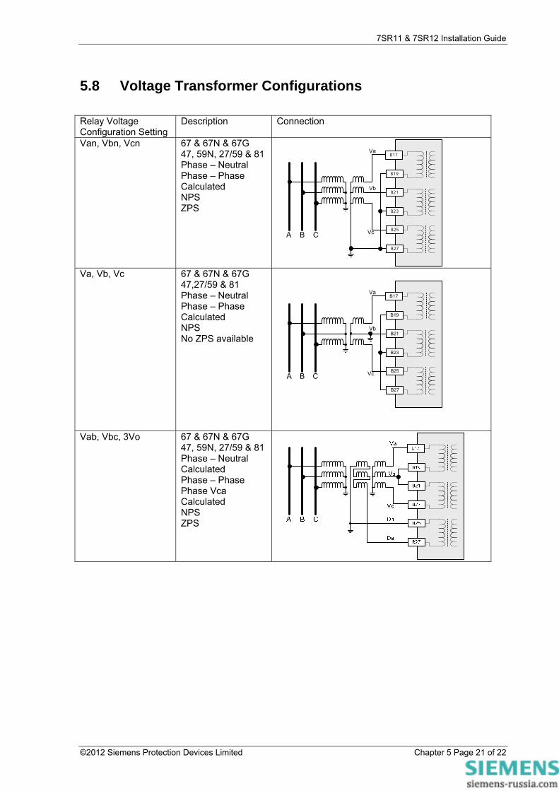
5.8 Voltage Transformer Configurations Relay Voltage Configuration Setting
Description Connection
Van, Vbn, Vcn 67 & 67N & 67G 47, 59N, 27/59 & 81 Phase – Neutral Phase – Phase Calculated NPS ZPS
A B C
B17
B19
B21
B23
B25
B27
Va
Vb
Vc
Va, Vb, Vc 67 & 67N & 67G
47,27/59 & 81 Phase – Neutral Phase – Phase Calculated NPS No ZPS available
A B C
B17
B19
B21
B23
B25
B27
Va
Vb
Vc
Vab, Vbc, 3Vo 67 & 67N & 67G 47, 59N, 27/59 & 81 Phase – Neutral Calculated Phase – Phase Phase Vca Calculated NPS ZPS
©2012 Siemens Protection Devices Limited Chapter 5 Page 21 of 22
7SR11 & 7SR12 Installation Guide
Section 6: Data Comms Connections
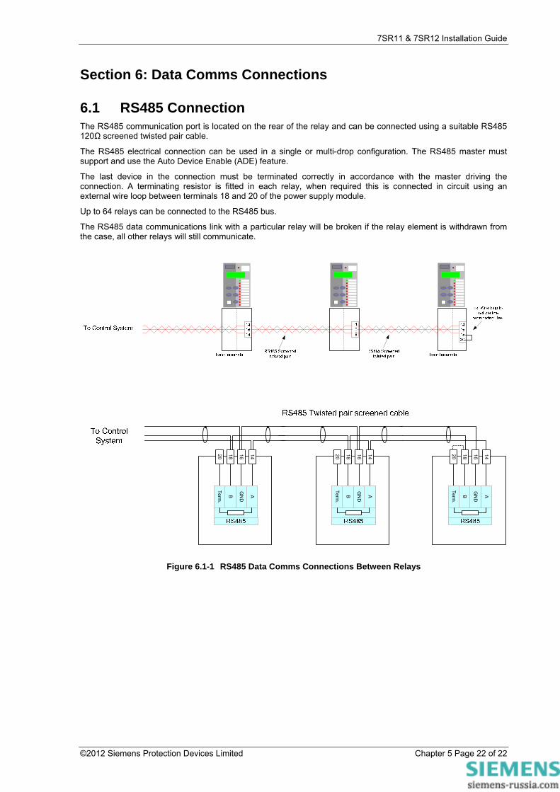
6.1 RS485 Connection The RS485 communication port is located on the rear of the relay and can be connected using a suitable RS485 120Ω screened twisted pair cable.
The RS485 electrical connection can be used in a single or multi-drop configuration. The RS485 master must support and use the Auto Device Enable (ADE) feature.
The last device in the connection must be terminated correctly in accordance with the master driving the connection. A terminating resistor is fitted in each relay, when required this is connected in circuit using an external wire loop between terminals 18 and 20 of the power supply module.
Up to 64 relays can be connected to the RS485 bus.
The RS485 data communications link with a particular relay will be broken if the relay element is withdrawn from the case, all other relays will still communicate.
A
GN
D
B
Term
.
14161820
A
GN
D
B
Term
.
14161820
A
GN
D
B
Term
.
14161820
Figure 6.1-1 RS485 Data Comms Connections Between Relays
©2012 Siemens Protection Devices Limited Chapter 5 Page 22 of 22