7a-3 g15-07 slope stability frank milchuck
TRANSCRIPT

5/5/2015
1
EARTH ANCHORING SYSTEMS FOR INFRASTRUCTURE APPLICATIONSEARTH ANCHORING SYSTEMS FOR INFRASTRUCTURE APPLICATIONS
Frank Milchuck – Sales Director
THE CONCEPT
The Percussion Driven Earth Anchor (PDEA) was originally developed in 1983 as a unique, modern and versatile device that could be rapidly deployed in most displaceable ground conditions.
The original design provided a lightweight corrosion resistant anchor that did not disturb the soil during installation. It could be driven from ground level using conventional portable equipment, could be pulled to an exact holding capacity and fully operational immediately.
5/5/2015
2
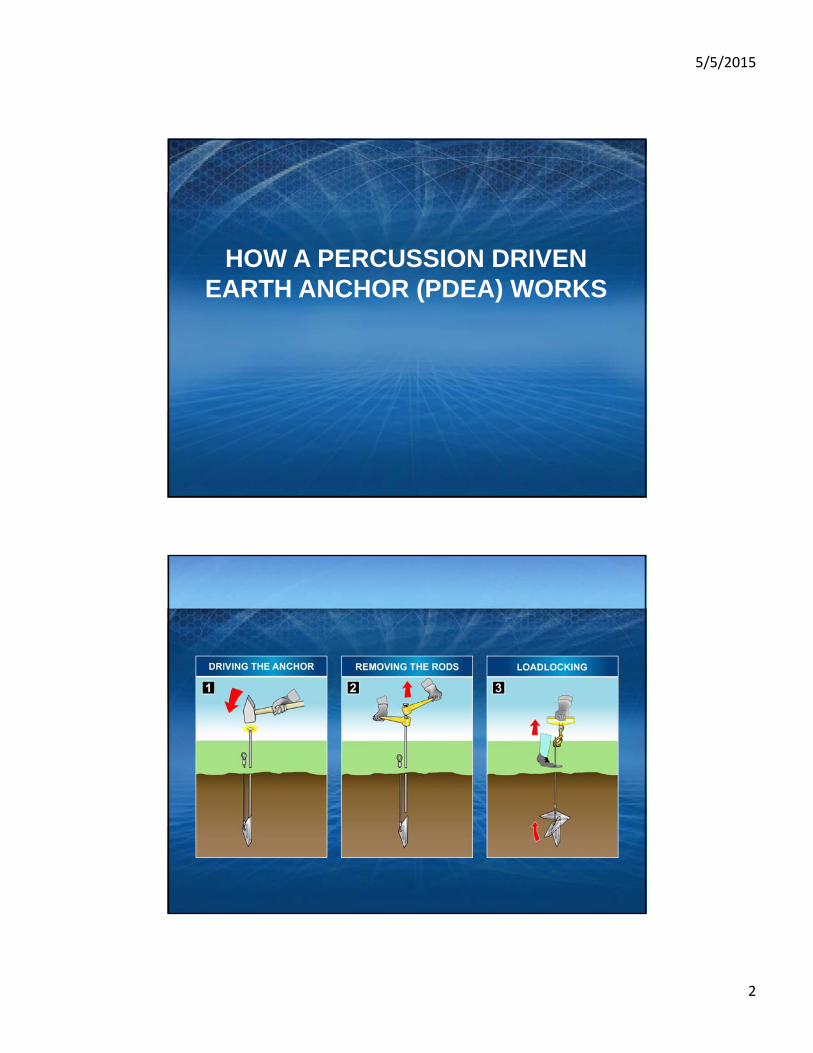
HOW A PERCUSSION DRIVEN EARTH ANCHOR (PDEA) WORKS

5/5/2015
3
FRUSTUM CONE
Due to the shape of the anchor and the offset attachment point of the wire tendon, when a load is applied, the anchor will rotate in the ground by up to 90° and loadlock.
As the load exerted on the soil by the anchor system increases, a body of soil above the anchor is compressed and provides resistance to any further anchor movement. The size and spread of this body of soil can be visualized as being a truncated cone or frustum. We refer to this soil as the Frustum Cone.
The size and spread of a Frustum Cone will depend upon:
• The shear angle of the soil• The size of the anchor• The depth of installation• The load applied
The first stage of the graph is where a load is applied to move the anchor into its loadlocked position. Elements of both load and extension are present.
LOADLOCK

5/5/2015
4
The second stage of the graph is where the anchor system is generating its frustum cone. At this stage load normally increases with minimum extension. The nature of the material in which the anchor is placed will affect the potential extension.
COMPACTION AND LOAD
This is the section between working load and ultimate load. As the anchor load approaches the bearing capacity of the soil, the rate of increase in load will reduce until bearing capacity failure of the soil takes place.
MAXIMUM LOAD RANGE

5/5/2015
5
When the mechanical shear strength of the soil has been exceeded, the residual load will decrease with continued extension as the anchor shears through the ground.
BEARING CAPACITY FAILURE
A typical non-cohesive soil consists of particles which interlock, bond and compact when subjected to a load. Coarser sands (ranging from 0.6mm -2mm) and gravels (coarser than 2mm) are generally of this composition.
Our anchor systems perform exceptionally well in free draining non-cohesive granular soils, displaying shorter loadlock and extension characteristics, larger frustum cones and higher loads.
NON-COHESIVE SOIL

5/5/2015
6
PECK HANSON & THORNBURN
Ultimate Bearing Capacity of Mechanical Anchor = Effective overburden pressure x Bearing Capacity
Coefficient x Shape Factor x projected area of anchor plate
qf = p0 x Nq x S x A
In a typical cohesive soil, the mineral particles are of 'Plate-like' form. The space between each of the 'Plates' contains water which dissipates when subjected to load. Gravelly or sandy silts and clays with particles finer than 0.002mm are generally of this composition.
Cohesive soil represents the weakest material to anchor into and generates the smallest frustum cone and lowest loads.
COHESIVE SOIL
5/5/2015
7
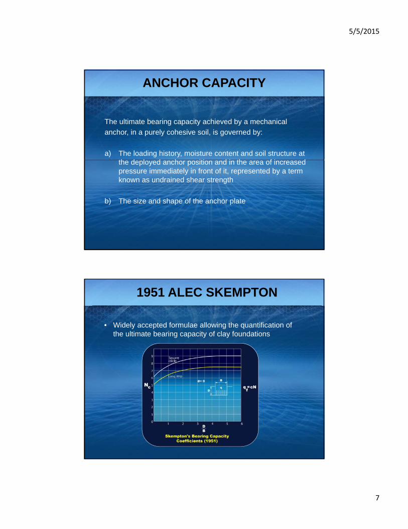
ANCHOR CAPACITY
The ultimate bearing capacity achieved by a mechanical
anchor, in a purely cohesive soil, is governed by:
a) The loading history, moisture content and soil structure at the deployed anchor position and in the area of increased pressure immediately in front of it, represented by a term known as undrained shear strength
b) The size and shape of the anchor plate
1951 ALEC SKEMPTON
• Widely accepted formulae allowing the quantification of the ultimate bearing capacity of clay foundations
5/5/2015
8
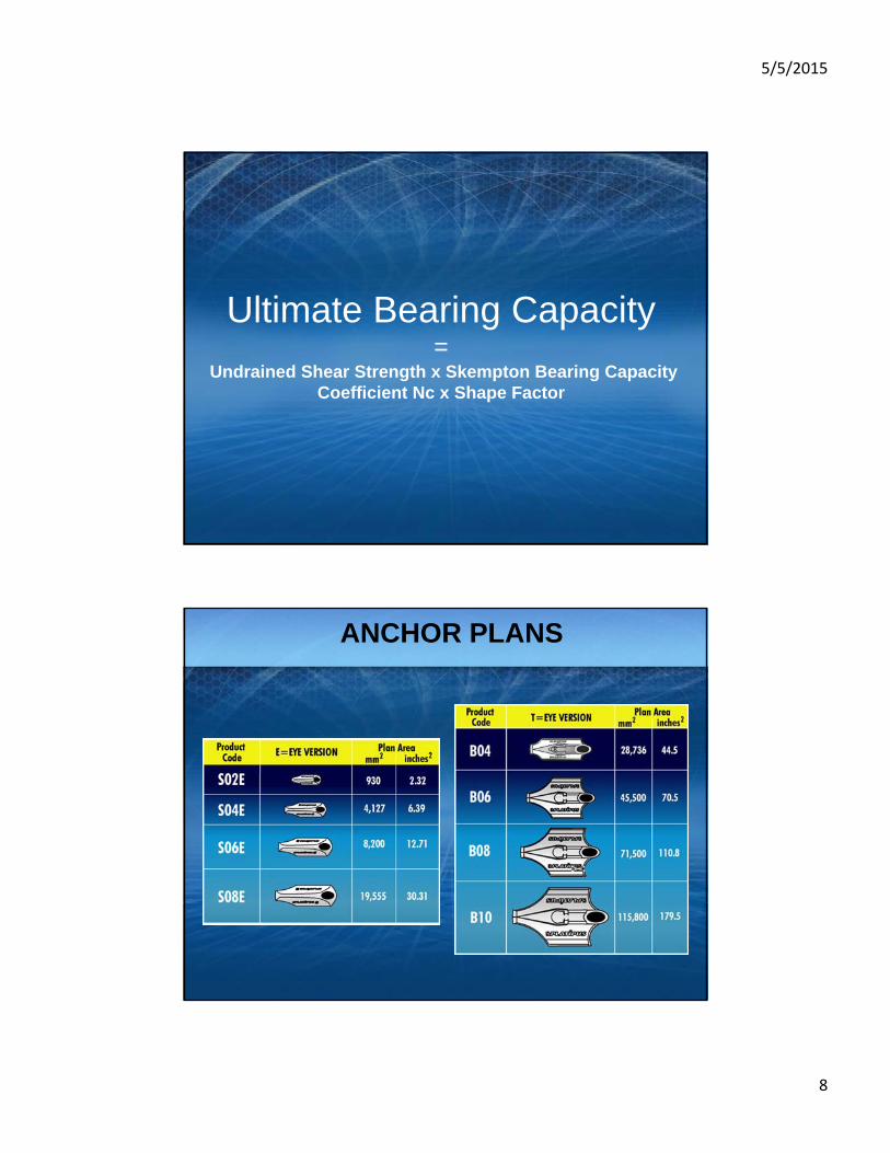
Ultimate Bearing Capacity=
Undrained Shear Strength x Skempton Bearing Capacity Coefficient Nc x Shape Factor
ANCHOR PLANS

5/5/2015
9
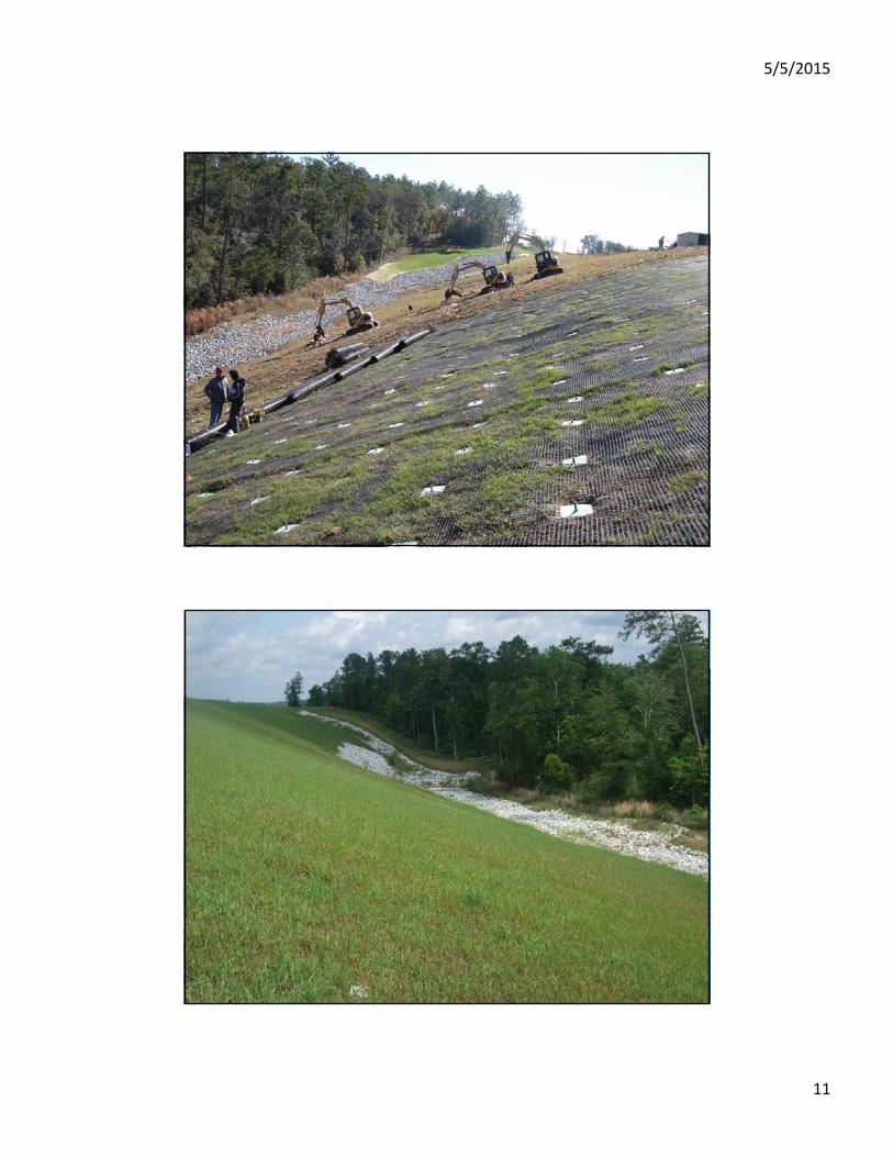
PRACTICAL APPLICATION
SHALLOW PLANE FAILURES

5/5/2015
10
DESIGN CONSIDERATIONS
1. What is the soil type/conditions where the anchor will reside?
2. What is the slope angle?
3. What is the vertical hgt.of the embankment?
4. How deep is the failure plane?
5. Is there pore water pressure within the embankment?
6. Using a standard geotechnical embankment stabilization program, how much load needs to be applied to the surface to stabilize the slope?
7. What is the factor of safety (usually between 1.2 to 1.5)?
8. What is the design life?
ALDOT HWY 98
5/5/2015
11

5/5/2015
12
NCDOT US1 SLOPE FAILURE
5/5/2015
13
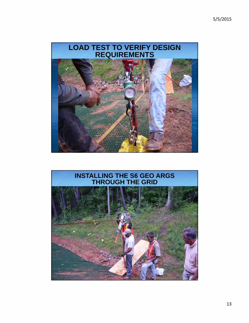
LOAD TEST TO VERIFY DESIGN REQUIREMENTS
INSTALLING THE S6 GEO ARGS THROUGH THE GRID

5/5/2015
14
NCDOT SOUTHPORT FERRY TERMINAL

5/5/2015
15
Mariscal Sucre International Airport, Quito Ecuado

5/5/2015
16
ANY QUESTIONS?