77 series iii - teslaoldradio.tesla.hu/rajzok/muszerek/fluke77multimeter.pdf · 77 series iii...
TRANSCRIPT
®
77 Series IIIMultimeter
Service Manual
PN 800604November 1998 Rev.1, 11/99© 1998,1999 Fluke Corporation. All rights reserved. Printed in U.S.A.All product names are trademarks of their respective companies.
i
Table of Contents
Chapter Title Page
1 Introduction and Specifications ................................. 1-11-1. Introduction ................................................................. 1-31-2. Organization of the Service Manual ........................... 1-31-3. Conventions ................................................................ 1-41-4. Specifications .............................................................. 1-4
2 Theory of Operation .................................................... 2-12-1. Introduction ................................................................. 2-32-2. Functional Block Description ..................................... 2-32-3. Detailed Description ................................................... 2-32-4. Voltage Signal Conditioning .................................. 2-32-5. Current Conditioning .............................................. 2-42-6. Ohms ....................................................................... 2-42-7. Additional Circuitry ................................................ 2-42-8. AC Converter ..................................................... 2-52-9. Active Filter ....................................................... 2-52-10. Rotary Switch ..................................................... 2-52-11. A/D Conversion .................................................. 2-5
3 Maintenance ................................................................ 3-13-1. Introduction ................................................................. 3-33-2. PCA Access and General Maintenance ...................... 3-33-3. Display Access ............................................................ 3-43-4. Cleaning ...................................................................... 3-43-5. Performance Test ........................................................ 3-73-6. Initial Procedure ..................................................... 3-73-7. DC Voltage Test ..................................................... 3-73-8. AC Voltage Test ......................................................... 3-83-9. Resistance Test ....................................................... 3-8
77 Series IIIService Manual
ii
3-10. Diode Test .............................................................. 3-93-11. DC mA Test ............................................................ 3-103-12. DC Amps Test ........................................................ 3-113-13. Calibration .............................................................. 3-113-14. Troubleshooting .......................................................... 3-113-15. Supplemental Troubleshooting Procedures ............ 3-133-16. Checking the Crystal Oscillator ......................... 3-133-17. Checking The Reference Voltage ...................... 3-133-18. Checking Display Drive Voltage ....................... 3-133-19. Checking Beeper Drive Signal ........................... 3-133-20. Tracing the VDC Signal Path ............................. 3-13
4 List of Replaceable Parts............................................ 4-14-1. Introduction ................................................................. 4-34-2. How to Obtain Parts .................................................... 4-34-3. Newer Instruments ...................................................... 4-34-4. Service Centers ........................................................... 4-34-5. Manual Status Information ......................................... 4-44-6. Parts Lists .................................................................... 4-4
5 Schematic Diagrams ................................................... 5-1
iii
List of Tables
Table Title Page
1-1. Specifications ..................................................................... 1-52-1. S1 Function Codes.............................................................. 2-63-1. Recommended Test Equipment.......................................... 3-33-2. DC Voltage Test ................................................................. 3-83-3. AC Voltage Test ................................................................. 3-83-4. Resistance Test ................................................................... 3-103-5. DC mA Test........................................................................ 3-113-6. DC Amps Test .................................................................... 3-114-1. Final Assembly................................................................... 4-54-2. A1 Main PCA..................................................................... 4-75-1. Abbreviations ..................................................................... 5-3

77 Series IIIService Manual
iv
v
List of Figures
Figure Title Page
2-1. Overview ............................................................................ 2-32-2. AC and A/D Converter ....................................................... 2-73-1. Assembly Details................................................................ 3-63-2. Troubleshooting Tree ......................................................... 3-124-2. A1 Main PCA..................................................................... 4-95-1. A1 Main PCA..................................................................... 5-4

77 Series IIIService Manual
vi
SAFETY-1
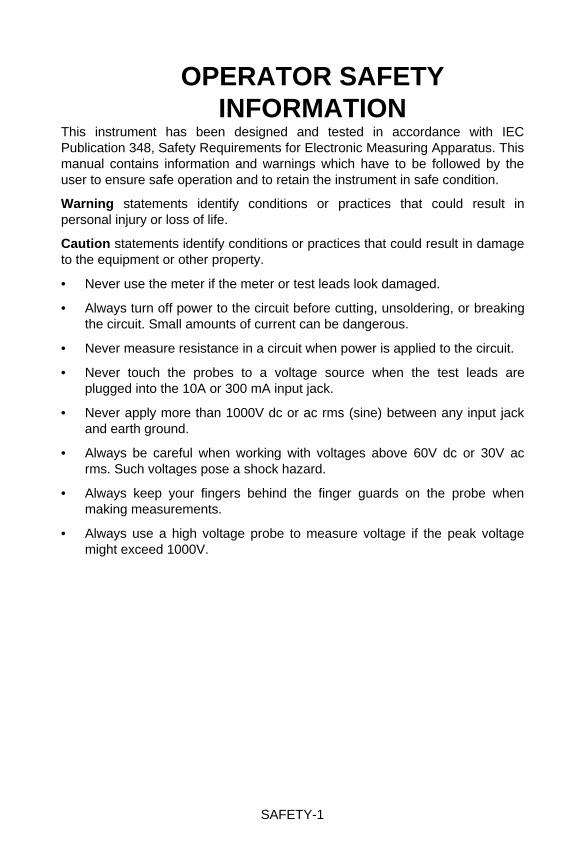
OPERATOR SAFETYINFORMATION
This instrument has been designed and tested in accordance with IECPublication 348, Safety Requirements for Electronic Measuring Apparatus. Thismanual contains information and warnings which have to be followed by theuser to ensure safe operation and to retain the instrument in safe condition.
Warning statements identify conditions or practices that could result inpersonal injury or loss of life.
Caution statements identify conditions or practices that could result in damageto the equipment or other property.
• Never use the meter if the meter or test leads look damaged.
• Always turn off power to the circuit before cutting, unsoldering, or breakingthe circuit. Small amounts of current can be dangerous.
• Never measure resistance in a circuit when power is applied to the circuit.
• Never touch the probes to a voltage source when the test leads areplugged into the 10A or 300 mA input jack.
• Never apply more than 1000V dc or ac rms (sine) between any input jackand earth ground.
• Always be careful when working with voltages above 60V dc or 30V acrms. Such voltages pose a shock hazard.
• Always keep your fingers behind the finger guards on the probe whenmaking measurements.
• Always use a high voltage probe to measure voltage if the peak voltagemight exceed 1000V.
SAFETY-2
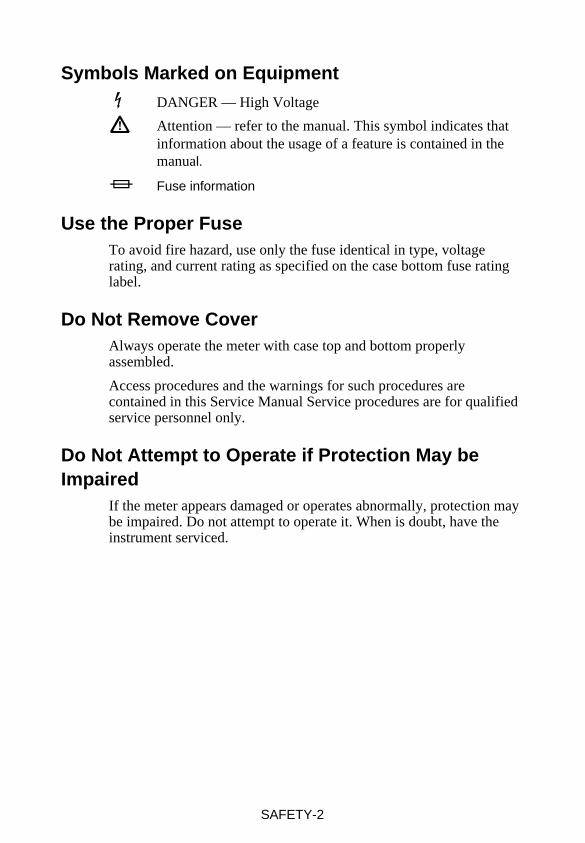
Symbols Marked on Equipment DANGER — High Voltage
Attention — refer to the manual. This symbol indicates thatinformation about the usage of a feature is contained in themanual.
I Fuse information
Use the Proper FuseTo avoid fire hazard, use only the fuse identical in type, voltagerating, and current rating as specified on the case bottom fuse ratinglabel.
Do Not Remove CoverAlways operate the meter with case top and bottom properlyassembled.
Access procedures and the warnings for such procedures arecontained in this Service Manual Service procedures are for qualifiedservice personnel only.
Do Not Attempt to Operate if Protection May beImpaired
If the meter appears damaged or operates abnormally, protection maybe impaired. Do not attempt to operate it. When is doubt, have theinstrument serviced.
1-1
Chapter 1Introduction and
Specifications
Contents Page
1-1. Introduction.................................................................. 1-31-2. Organization of the Service Manual ............................ 1-31-3. Conventions ................................................................. 1-41-4. Specifications............................................................... 1-4

77 Series IIIService Manual
1-2
Introduction and SpecificationsIntroduction 1
1-3
1-1. IntroductionThis manual presents service information for the Fluke 77 Series IIIMultimeter. The manual includes a theory of operation, general maintenanceprocedures, performance tests, calibration procedures, troubleshootinginformation, a list of replaceable parts, and schematic diagrams.
A meter under warranty will be promptly repaired or replaced (at Fluke’soption) and returned at no charge. See the registration card for warranty terms.To locate an authorized service center, visit us on the World Wide Web:www.fluke.com or call using any of the phone numbers listed below:
USA: 1-888-99-FLUKE (1-888-993-5853)Canada: 1-800-36-FLUKE (1-800-363-5853)Europe: +31 402-678-200Japan: +81-3-3434-0181Singapore: +65-738-5655Anywhere in the world: +1-425-446-5500
1-2. Organization of the Service ManualThe following descriptions briefly describe each chapter in the manual.
Chapter 1 Introduction and SpecificationsThis chapter describes use of the Service Manual and application of specialterminology (conventions) to describe the meter’s circuitry. A complete set ofspecifications appears at the end of this chapter.
Chapter 2 Theory of OperationThis chapter first categorizes instrument circuitry into functional blocks, witha description of each block’s role in overall operation. A detailed circuitdescription is then given for each block. These descriptions explore operationto the component level and fully support troubleshooting and repairprocedures defined in Section 3.
Chapter 3 MaintenanceProvides complete maintenance information, from general maintenance andcleaning instructions to detailed troubleshooting and repair procedures to thecomponent level. Troubleshooting and repair procedures rely heavily on boththe Theory of Operation presented in Chapter 2 and the Schematic Diagramsshown in Section 5.
Chapter 4 List of Replaceable PartsIncludes parts lists for all standard assemblies. Information on how and whereto order parts is also provided.
Chapter 5 Schematic DiagramsIncludes schematic for the A1 Main PCA.
77 Series IIIService Manual
1-4
1-3. ConventionsThrough the manual, certain notational conventions are used. A summary ofthese conventions follow:
• Instrument Reference
The Fluke 77 Series III Multimeter is also referred to throughout thismanual as “the meter”.
• Printed Circuit Assembly
The term “pca” is used to represent a printed wiring board and itsattached parts.
• Circuit Nodes
Individual pins or connections on a component are specified by a dash(-) following the component reference designator. For example, pin 19of U30 would be U30-19.
• User Notation
Generally, push buttons, function positions, input terminals, anddisplay notation are presented in this manual as they are seen on themeter.
Special terms (mnemonics) used in text descriptions of meter circuitrycorrespond to terms used on the schematic diagrams in Chapter 5.
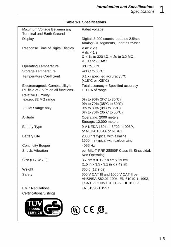
1-4. SpecificationsSpecifications for the meters are presented in Table 1-1.
Introduction and SpecificationsSpecifications 1
1-5
Table 1-1. Specifications
Maximum Voltage Between anyTerminal and Earth Ground
Rated voltage
Display Digital: 3,200 counts, updates 2.5/secAnalog: 31 segments, updates 25/sec
Response Time of Digital Display V ac < 2 sV dc < 1 sΩ < 1s to 320 kΩ, < 2s to 3.2 MΩ,< 10 s to 32 MΩ
Operating Temperature 0°C to 50°CStorage Temperature -40°C to 60°CTemperature Coefficient 0.1 x (specified accuracy)/°C
(<18°C or >28°C)
Electromagnetic Compatibility InRF field of 3 V/m on all functions.
Total accuracy = Specified accuracy+ 0.1% of range.
Relative Humidityexcept 32 MΩ range
32 MΩ range only
0% to 90% (0°C to 35°C)0% to 70% (35°C to 50°C)0% to 80% (0°C to 35°C)0% to 70% (35°C to 50°C)
Altitude Operating: 2000 metersStorage: 12,000 meters
Battery Type 9 V NEDA 1604 or 6F22 or 006P,or NEDA 1604A or 6LR61
Battery Life 2000 hrs typical with alkaline1600 hrs typical with carbon zinc
Continuity Beeper 4096 Hz
Shock, Vibration per MIL-T-PRF 28800F Class III, Sinusoidal,Non Operating
Size (H x W x L) 3.7 cm x 8.9 - 7.8 cm x 19 cm(1.5 in x 3.5 - 3.1 in x 7.49 in)
Weight 365 g (12.9 oz)
Safety 600 V CAT III and 1000 V CAT II perANSI/ISA S82.01-1994, EN 61010-1: 1993,CSA C22.2 No 1010.1-92, UL 3111-1.
EMC Regulations EN 61326-1 1997.
Certifications/Listings
77 Series IIIService Manual
1-6
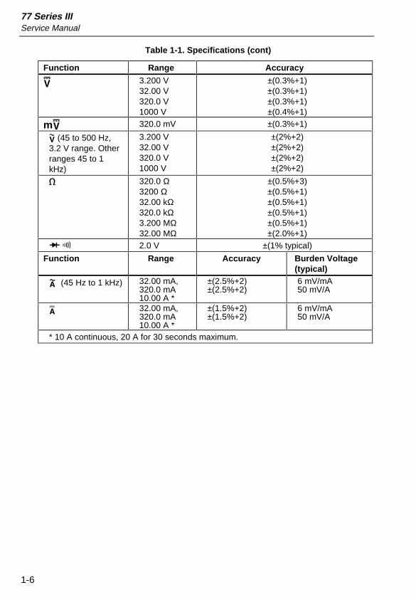
Table 1-1. Specifications (cont)
Function Range Accuracy
L 3.200 V32.00 V320.0 V1000 V
±(0.3%+1)±(0.3%+1)±(0.3%+1)±(0.4%+1)
mL 320.0 mV ±(0.3%+1)
K (45 to 500 Hz,3.2 V range. Otherranges 45 to 1kHz)
3.200 V32.00 V320.0 V1000 V
±(2%+2)±(2%+2)±(2%+2)±(2%+2)
e 320.0 Ω3200 Ω32.00 kΩ320.0 kΩ3.200 MΩ32.00 MΩ
±(0.5%+3)±(0.5%+1)±(0.5%+1)±(0.5%+1)±(0.5%+1)±(2.0%+1)
G R 2.0 V ±(1% typical)
Function Range Accuracy Burden Voltage(typical)
? (45 Hz to 1 kHz) 32.00 mA,320.0 mA10.00 A *
±(2.5%+2)±(2.5%+2)
6 mV/mA50 mV/A
A 32.00 mA,320.0 mA10.00 A *
±(1.5%+2)±(1.5%+2)
6 mV/mA50 mV/A
* 10 A continuous, 20 A for 30 seconds maximum.
Introduction and SpecificationsSpecifications 1
1-7
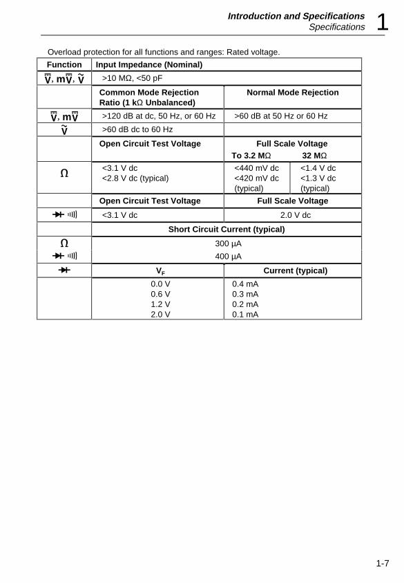
Overload protection for all functions and ranges: Rated voltage.
Function Input Impedance (Nominal)
L, mL, K >10 MΩ, <50 pF
Common Mode RejectionRatio (1 kΩ Unbalanced)
Normal Mode Rejection
L, mL >120 dB at dc, 50 Hz, or 60 Hz >60 dB at 50 Hz or 60 Hz
K >60 dB dc to 60 Hz
Open Circuit Test Voltage Full Scale VoltageTo 3.2 MΩ 32 MΩ
e<3.1 V dc<2.8 V dc (typical)
<440 mV dc<420 mV dc(typical)
<1.4 V dc<1.3 V dc(typical)
Open Circuit Test Voltage Full Scale Voltage
G R <3.1 V dc 2.0 V dc
Short Circuit Current (typical)
e 300 µA
G R 400 µA
G VF Current (typical)
0.0 V0.6 V1.2 V2.0 V
0.4 mA0.3 mA0.2 mA0.1 mA

77 Series IIIService Manual
1-8
2-1
Chapter 2Theory of Operation
Contents Page
2-1. Introduction.................................................................. 2-32-2. Functional Block Description ...................................... 2-32-3. Detailed Description .................................................... 2-32-4. Voltage Signal Conditioning ................................... 2-32-5. Current Conditioning............................................... 2-42-6. Ohms........................................................................ 2-42-7. Additional Circuitry................................................. 2-42-8. AC Converter ...................................................... 2-42-9. Active Filter ........................................................ 2-52-10. Rotary Switch...................................................... 2-52-11. A/D Conversion................................................... 2-5

77 Series IIIService Manual
2-2
Theory of OperationIntroduction 2
2-3
2-1. IntroductionThis chapter contains a brief overview of the 77 Series III Multimeter,followed by a more detailed explanation of operation.
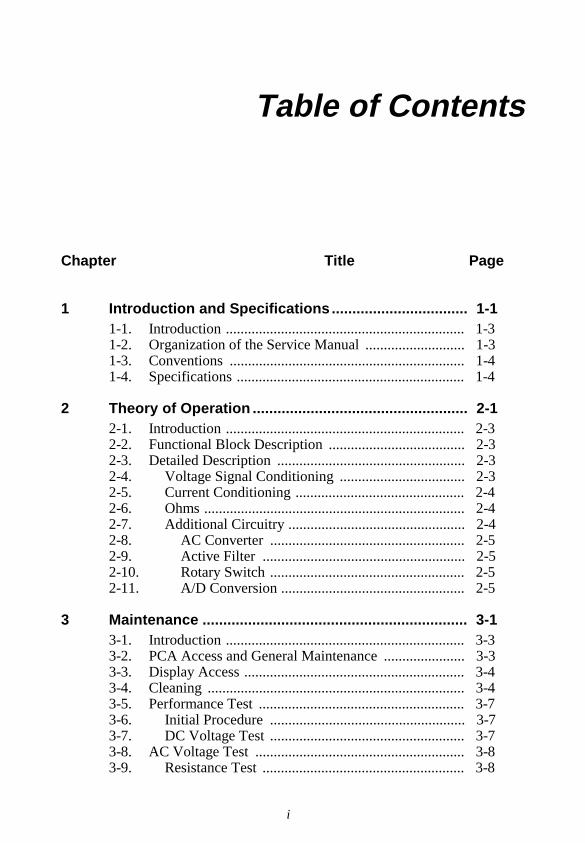
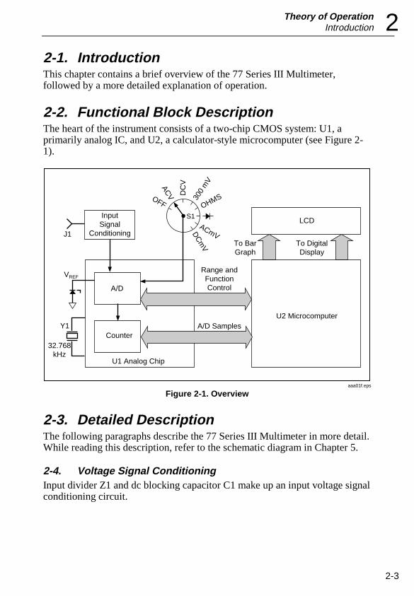
2-2. Functional Block DescriptionThe heart of the instrument consists of a two-chip CMOS system: U1, aprimarily analog IC, and U2, a calculator-style microcomputer (see Figure 2-1).
OHMS300
mV
DC
VACVOFF
ACmVDC
mV
A/D
J1
InputSignal
Conditioning
Range andFunctionControl
To BarGraph
To DigitalDisplay
LCDS1
U2 MicrocomputerA/D SamplesY1
32.768kHz
Counter
U1 Analog Chip
VREF
aaa01f.eps
Figure 2-1. Overview
2-3. Detailed DescriptionThe following paragraphs describe the 77 Series III Multimeter in more detail.While reading this description, refer to the schematic diagram in Chapter 5.
2-4. Voltage Signal ConditioningInput divider Z1 and dc blocking capacitor C1 make up an input voltage signalconditioning circuit.
77 Series IIIService Manual
2-4
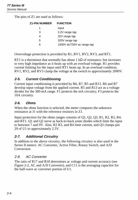
The pins of Z1 are used as follows:
Z1-PIN NUMBER FUNCTION
1 input
3 3.2V range tap
4 32V range tap
5 320V range tap
6 1000V dc/750V ac range tap
Overvoltage protection is provided by R1, RV1, RV2, RV3, and RT1.
RT1 is a thermistor that normally has about 1 kΩ of resistance, but increasesto very high impedance as it heats up with an overload voltage. R1 providescurrent limiting for the input until RT1 heats up. In an overload condition,RV1, RV2, and RV3 clamp the voltage at the switch to approximately 2000V.
2-5. Current ConditioningCurrent input conditioning is provided by R6, R7, R5 and R13. R6 and R7develop input voltage from the applied current. R5 and R13 act as a voltagedivider for the 300-mA range. F1 protects the mA circuitry; F3 protects the10A circuitry.
2-6. OhmsWhen the ohms function is selected, the meter compares the unknownresistance at J1 with the reference resistors in Z1.
Input protection for the ohms ranges consists of Q1, Q2, Q3, R1, R2, R3, R4,and RT1. Q1 and Q2 serve as back-to-back zener diodes which limit the inputto between 7 and 9V. Also, R2 R3, and R4 limit current, and Q3 clamps pin29 of U1 to approximately 2.5V.
2-7. Additional CircuitryIn addition to the above circuitry, the following circuitry is also used in theSeries II meters: AC Converter, Active Filter, Rotary Switch, and A/DConversion.
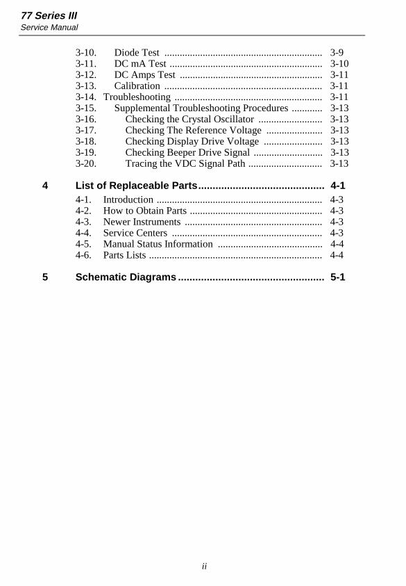
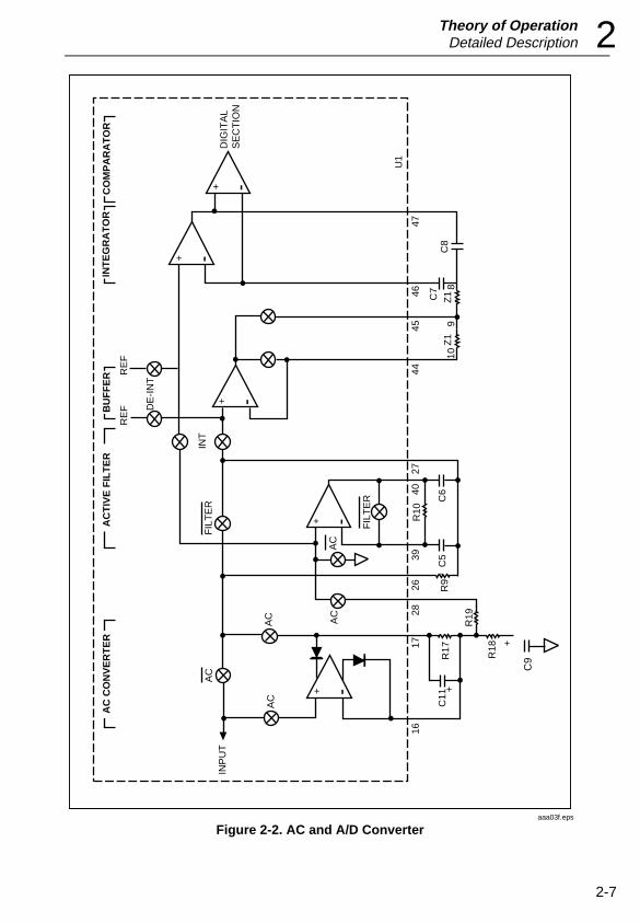
2-8. AC ConverterThe ratio of R17 and R18 determines ac voltage and current accuracy (seeFigure 2-2, AC and A/D Converter), and C11 is the averaging capacitor forthe half-wave ac converter portion of U1.
Theory of OperationDetailed Description 2
2-5
2-9. Active FilterAn active filter that includes R9, R10, C5, and C6 is located in U1.Conditioned input signals are passed through the active filter in route to thea/d converter section of U1. (See Figure 2-2, AC and A/D Converter.)
The clock frequency for the digital portion of the circuit is a function of32.768-kHz crystal Y1. Y1, C12, C15, and amplifiers in U1 make up theoscillator circuit.
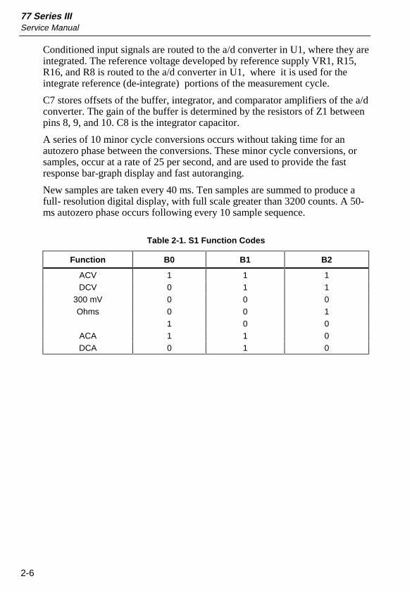
2-10. Rotary SwitchRotary switch S1 FRONT selects and routes the input signals. Function codesfor switch S1 REAR are shown in Table 2-1. Range switch S2 signals themicrocomputer U2 for the manual ranging and automatic Touch Holdfunction.
CR1 acts as protection for U1 if the battery is installed backwards. C2 is partof the power-on reset for microcomputer U2.
2-11. A/D ConversionAnalog-to-digital (a/d) conversion is accomplished within U1 using amodified dualslope a/d converter circuit. (See Figure 2-2, AC and A/DConverter.)
Since the a/d conversion process is essentially a dual slope method, twovoltages are required to complete a measurement cycle. One is the unknowninput and the other is the reference voltage.
77 Series IIIService Manual
2-6
Conditioned input signals are routed to the a/d converter in U1, where they areintegrated. The reference voltage developed by reference supply VR1, R15,R16, and R8 is routed to the a/d converter in U1, where it is used for theintegrate reference (de-integrate) portions of the measurement cycle.
C7 stores offsets of the buffer, integrator, and comparator amplifiers of the a/dconverter. The gain of the buffer is determined by the resistors of Z1 betweenpins 8, 9, and 10. C8 is the integrator capacitor.
A series of 10 minor cycle conversions occurs without taking time for anautozero phase between the conversions. These minor cycle conversions, orsamples, occur at a rate of 25 per second, and are used to provide the fastresponse bar-graph display and fast autoranging.
New samples are taken every 40 ms. Ten samples are summed to produce afull- resolution digital display, with full scale greater than 3200 counts. A 50-ms autozero phase occurs following every 10 sample sequence.
Table 2-1. S1 Function Codes
Function B0 B1 B2
ACV 1 1 1DCV 0 1 1
300 mV 0 0 0Ohms 0 0 1
1 0 0ACA 1 1 0DCA 0 1 0
Theory of OperationDetailed Description 2
2-7
AC
AC
AC
AC
AC
FIL
TE
R
FIL
TE
R
R10
C11
C5
C6
C8
C7
C9
+
+
R18
R19
R17
R9
1617
2826
3940
2744
45
109
8
4647
INP
UT
DIG
ITA
LS
EC
TIO
N
Z1
Z1
+
+
+
++
INT
DE
-IN
T
RE
FR
EF
AC
CO
NV
ER
TE
RA
CT
IVE
FIL
TE
RB
UF
FE
RIN
TE
GR
AT
OR
CO
MP
AR
AT
OR
U1
aaa03f.eps
Figure 2-2. AC and A/D Converter

77 Series IIIService Manual
2-8
3-1
Chapter 3Maintenance
Contents Page
3-1. Introduction..................................................................... 3-33-2. PCA Access and General Maintenance .......................... 3-33-3. Display Access................................................................ 3-43-4. Cleaning .......................................................................... 3-43-5. Performance Test ............................................................ 3-73-6. Initial Procedure ......................................................... 3-73-7. DC Voltage Test ......................................................... 3-73-8. AC Voltage Test ............................................................. 3-83-9. Resistance Test ........................................................... 3-83-10. Diode Test .................................................................. 3-93-11. DC mA Test................................................................ 3-103-12. DC Amps Test ............................................................ 3-113-13. Calibration .................................................................. 3-113-14. Troubleshooting .............................................................. 3-113-15. Supplemental Troubleshooting Procedures................ 3-133-16. Checking the Crystal Oscillator ............................. 3-133-17. Checking The Reference Voltage .......................... 3-133-18. Checking Display Drive Voltage ........................... 3-133-19. Checking Beeper Drive Signal ............................... 3-133-20. Tracing the VDC Signal Path................................. 3-13

77 Series IIIService Manual
3-2
MaintenanceIntroduction 3
3-3
WarningThese service instructions are for use by qualifiedpersonnel only. To avoid electric shock, do notperform any servicing other than that contained inthe operator’s manual unless you are qualified to doso.
3-1. IntroductionThis chapter contains maintenance information for the performance testing,calibration, general maintenance, and troubleshooting of the 77 Series IIIMultimeter. For operator maintenance, refer to the Instruction Sheet.
The performance tests are recommended as a preventive maintenance tool toverify proper instrument operation. A one year calibration cycle isrecommended to maintain the specifications given in the Users Manual. Testequipment required for the performance tests and calibration is listed in Table3-1. If the recommended equipment is not available, instruments withequivalent specifications may be used.
Table 3-1. Recommended Test Equipment
Instrument Type Recommended Model
Multi-Product Calibrator Fluke 5500A
3-2. PCA Access and General Maintenance Warning
To avoid electrical shock, remove the test leadsbefore opening the case, and close the case beforeoperating the meter. To prevent fire, install fuseswith the rating shown on the back of the meter.
CautionTo avoid contaminating the pca with oil from thefingers, handle it by the edges or wear gloves. PCAcontamination may not cause immediate instrumentfailure in controlled environments. Failures typicallyshow up when contaminated units are operated inhumid areas.
Use the following procedure for removing the pca (printed circuit assembly)from its case:
77 Series IIIService Manual
3-4
1. Set the function switch to OFF, and disconnect test leads if they areinstalled.
2. Remove the four Phillips screws from the bottom cover.
3. Turn the meter face up, grasp the top cover, and pull the top coverfrom the meter.
4. Remove the 11A fuse to access the screw that holds the pca to thecase bottom.
5. The pca may now be removed from the bottom cover.
3-3. Display AccessCaution
Do not handle the conductive edges of the LCDinterconnects. If contaminated, clean with alcohol.
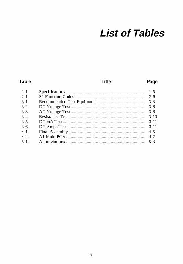
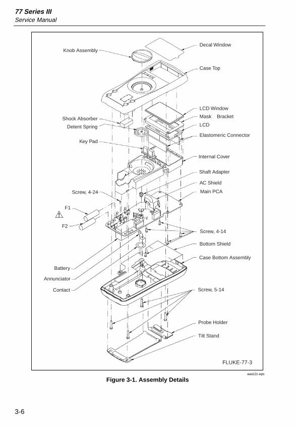
Refer to Figure 3-1.
1. Remove the four Phillips screws from the back side of the pca.
2. Remove the LCD mounting bracket.
3. Insert a small screwdriver under the edges of the display holdingbracket, and gently pry the bracket loose from the snaps.
4. Turn the bracket upside down to remove the LCD.
5. Before installing a new LCD, make sure that all connector contactpoints are clean.
3-4. CleaningCaution
To avoid damaging the meter, do not use aromatichydrocarbons or chlorinated solvents for cleaning.These solutions will react with the plastics used ininstruments.
Do not allow the LCD to get wet. Remove the displayassembly before washing the pca and do not installuntil the pca is completely dry.
Do not use detergent of any kind for cleaning thepca.
Do not remove lubricants from the switch whencleaning the pca.
MaintenanceCleaning 3
3-5
Clean the instrument case with a mild detergent and water.
The pca may be washed with isopropyl alcohol or deionized water and a softbrush. Remove the display assembly and fuses before washing, and avoidwashing the switch if possible. Dry the pca with clean dry air at low pressure,then bake it at 50°C for 24 hours.
77 Series IIIService Manual
3-6
Decal Window
Case Top
LCD Window
Mask Bracket
LCD
Elastomeric Connector
Internal Cover
Shaft Adapter
AC Shield
Main PCA
Screw, 4-14
Bottom Shield
Case Bottom Assembly
Screw, 5-14
Probe Holder
Tilt Stand
Knob Assembly
Shock Absorber
Detent Spring
Key Pad
Screw, 4-24
F1
F2
Battery
Annunciator
Contact
FLUKE-77-3
aaa12c.eps
Figure 3-1. Assembly Details
MaintenancePerformance Test 3
3-7
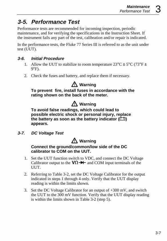
3-5. Performance TestPerformance tests are recommended for incoming inspection, periodicmaintenance, and for verifying the specifications in the Instruction Sheet. Ifthe instrument fails any part of the test, calibration and/or repair is indicated.
In the performance tests, the Fluke 77 Series III is referred to as the unit undertest (UUT).
3-6. Initial Procedure1. Allow the UUT to stabilize to room temperature 23°C ± 5°C (73°F ±
9°F).
2. Check the fuses and battery, and replace them if necessary.
WarningTo prevent fire, install fuses in accordance with therating shown on the back of the meter.
WarningTo avoid false readings, which could lead topossible electric shock or personal injury, replacethe battery as soon as the battery indicator (N)appears.
3-7. DC Voltage Test
WarningConnect the ground/common/low side of the DCcalibrator to COM on the UUT.
1. Set the UUT function switch to VDC, and connect the DC VoltageCalibrator output to the z and COM input terminals of theUUT.
2. Referring to Table 3-2, set the DC Voltage Calibrator for the outputindicated in steps 1 through 4 only. Verify that the UUT displayreading is within the limits shown.
3. Set the DC Voltage Calibrator for an output of +300 mV, and switchthe UUT to the 300 mV function. Verify that the UUT display readingis within the limits shown in Table 3-2 (step 5).
77 Series IIIService Manual
3-8
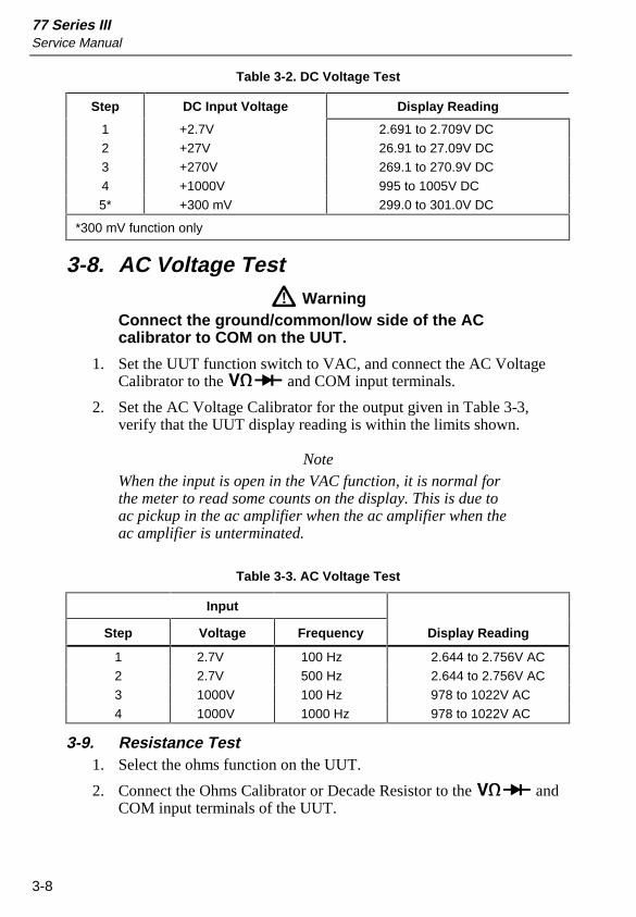
Table 3-2. DC Voltage Test
Step DC Input Voltage Display Reading
1 +2.7V 2.691 to 2.709V DC
2 +27V 26.91 to 27.09V DC
3 +270V 269.1 to 270.9V DC
4 +1000V 995 to 1005V DC
5* +300 mV 299.0 to 301.0V DC
*300 mV function only
3-8. AC Voltage Test Warning
Connect the ground/common/low side of the ACcalibrator to COM on the UUT.
1. Set the UUT function switch to VAC, and connect the AC VoltageCalibrator to the z and COM input terminals.
2. Set the AC Voltage Calibrator for the output given in Table 3-3,verify that the UUT display reading is within the limits shown.
NoteWhen the input is open in the VAC function, it is normal forthe meter to read some counts on the display. This is due toac pickup in the ac amplifier when the ac amplifier when theac amplifier is unterminated.
Table 3-3. AC Voltage Test
Input
Step Voltage Frequency Display Reading
1 2.7V 100 Hz 2.644 to 2.756V AC
2 2.7V 500 Hz 2.644 to 2.756V AC
3 1000V 100 Hz 978 to 1022V AC
4 1000V 1000 Hz 978 to 1022V AC
3-9. Resistance Test1. Select the ohms function on the UUT.
2. Connect the Ohms Calibrator or Decade Resistor to the z andCOM input terminals of the UUT.
MaintenanceAC Voltage Test 3
3-9
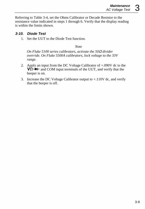
Referring to Table 3-4, set the Ohms Calibrator or Decade Resistor to theresistance value indicated in steps 1 through 6. Verify that the display readingis within the limits shown.
3-10. Diode Test1. Set the UUT to the Diode Test function.
NoteOn Fluke 5100 series calibrators, activate the 50Ω divideroverride. On Fluke 5500A calibrators, lock voltage to the 33Vrange.
2. Apply an input from the DC Voltage Calibrator of +.090V dc to thez and COM input terminals of the UUT, and verify that thebeeper is on.
3. Increase the DC Voltage Calibrator output to +.110V dc, and verifythat the beeper is off.
77 Series IIIService Manual
3-10
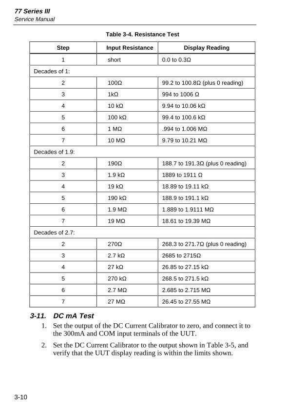
Table 3-4. Resistance Test
Step Input Resistance Display Reading
1 short 0.0 to 0.3Ω
Decades of 1:
2 100Ω 99.2 to 100.8Ω (plus 0 reading)
3 1kΩ 994 to 1006 Ω
4 10 kΩ 9.94 to 10.06 kΩ
5 100 kΩ 99.4 to 100.6 kΩ
6 1 MΩ .994 to 1.006 MΩ
7 10 MΩ 9.79 to 10.21 MΩ
Decades of 1.9:
2 190Ω 188.7 to 191.3Ω (plus 0 reading)
3 1.9 kΩ 1889 to 1911 Ω
4 19 kΩ 18.89 to 19.11 kΩ
5 190 kΩ 188.9 to 191.1 kΩ
6 1.9 MΩ 1.889 to 1.9111 MΩ
7 19 MΩ 18.61 to 19.39 MΩ
Decades of 2.7:
2 270Ω 268.3 to 271.7Ω (plus 0 reading)
3 2.7 kΩ 2685 to 2715Ω
4 27 kΩ 26.85 to 27.15 kΩ
5 270 kΩ 268.5 to 271.5 kΩ
6 2.7 MΩ 2.685 to 2.715 MΩ
7 27 MΩ 26.45 to 27.55 MΩ
3-11. DC mA Test1. Set the output of the DC Current Calibrator to zero, and connect it to
the 300mA and COM input terminals of the UUT.
2. Set the DC Current Calibrator to the output shown in Table 3-5, andverify that the UUT display reading is within the limits shown.
MaintenanceTroubleshooting 3
3-11
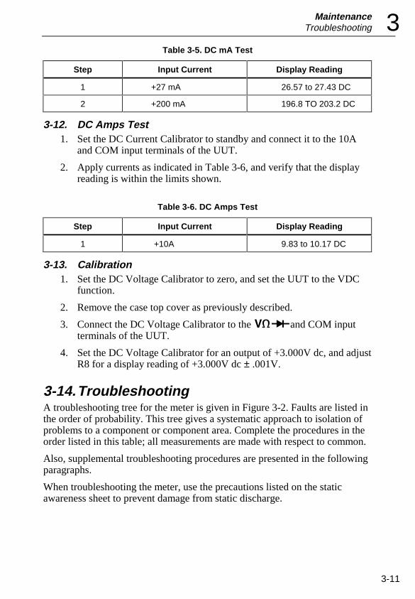
Table 3-5. DC mA Test
Step Input Current Display Reading
1 +27 mA 26.57 to 27.43 DC
2 +200 mA 196.8 TO 203.2 DC
3-12. DC Amps Test1. Set the DC Current Calibrator to standby and connect it to the 10A
and COM input terminals of the UUT.
2. Apply currents as indicated in Table 3-6, and verify that the displayreading is within the limits shown.
Table 3-6. DC Amps Test
Step Input Current Display Reading
1 +10A 9.83 to 10.17 DC
3-13. Calibration1. Set the DC Voltage Calibrator to zero, and set the UUT to the VDC
function.
2. Remove the case top cover as previously described.
3. Connect the DC Voltage Calibrator to the zand COM inputterminals of the UUT.
4. Set the DC Voltage Calibrator for an output of +3.000V dc, and adjustR8 for a display reading of +3.000V dc ± .001V.
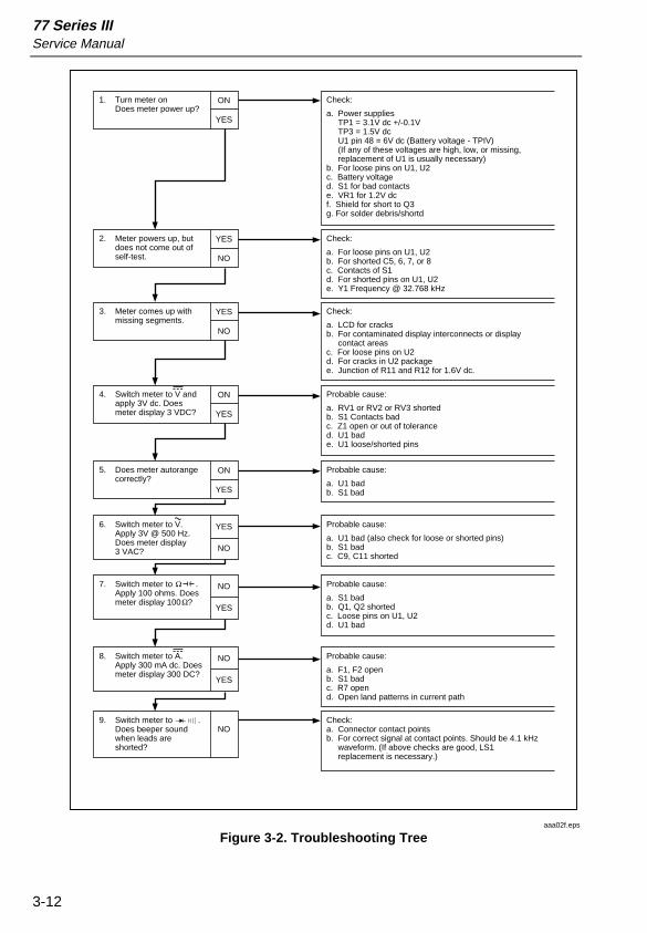
3-14. TroubleshootingA troubleshooting tree for the meter is given in Figure 3-2. Faults are listed inthe order of probability. This tree gives a systematic approach to isolation ofproblems to a component or component area. Complete the procedures in theorder listed in this table; all measurements are made with respect to common.
Also, supplemental troubleshooting procedures are presented in the followingparagraphs.
When troubleshooting the meter, use the precautions listed on the staticawareness sheet to prevent damage from static discharge.
77 Series IIIService Manual
3-12
Turn meter onDoes meter power up?
1. ON
YES
Check:
a. Power supplies TP1 = 3.1V dc +/-0.1V TP3 = 1.5V dc U1 pin 48 = 6V dc (Battery voltage - TPIV) (If any of these voltages are high, low, or missing, replacement of U1 is usually necessary)b. For loose pins on U1, U2c. Battery voltaged. S1 for bad contactse. VR1 for 1.2V dcf. Shield for short to Q3g. For solder debris/shortd
Meter powers up, but does not come out of self-test.
2. YES
NO
Check:
a. For loose pins on U1, U2b. For shorted C5, 6, 7, or 8c. Contacts of S1d. For shorted pins on U1, U2e. Y1 Frequency @ 32.768 kHz
Meter comes up with missing segments.
3. YES
NO
Check:
a. LCD for cracksb. For contaminated display interconnects or display contact areasc. For loose pins on U2d. For cracks in U2 packagee. Junction of R11 and R12 for 1.6V dc.
Switch meter to V and apply 3V dc. Does meter display 3 VDC?
4. ON
YES
Probable cause:
a. RV1 or RV2 or RV3 shortedb. S1 Contacts badc. Z1 open or out of toleranced. U1 bade. U1 loose/shorted pins
Does meter autorange correctly?
5. ON
YES
Probable cause:
a. U1 badb. S1 bad
Switch meter to V. Apply 3V @ 500 Hz. Does meter display 3 VAC?
6. YES
NO
Probable cause:
a. U1 bad (also check for loose or shorted pins)b. S1 badc. C9, C11 shorted
Switch meter to . Apply 100 ohms. Does meter display 100 ?
7. NO
YES
Probable cause:
a. S1 badb. Q1, Q2 shortedc. Loose pins on U1, U2d. U1 bad
Switch meter to A. Apply 300 mA dc. Does meter display 300 DC?
8. NO
YES
Probable cause:
a. F1, F2 openb. S1 badc. R7 opend. Open land patterns in current path
Switch meter to . Does beeper sound when leads are shorted?
9.NO
Check:a. Connector contact pointsb. For correct signal at contact points. Should be 4.1 kHz waveform. (If above checks are good, LS1 replacement is necessary.)
aaa02f.eps
Figure 3-2. Troubleshooting Tree
MaintenanceTroubleshooting 3
3-13
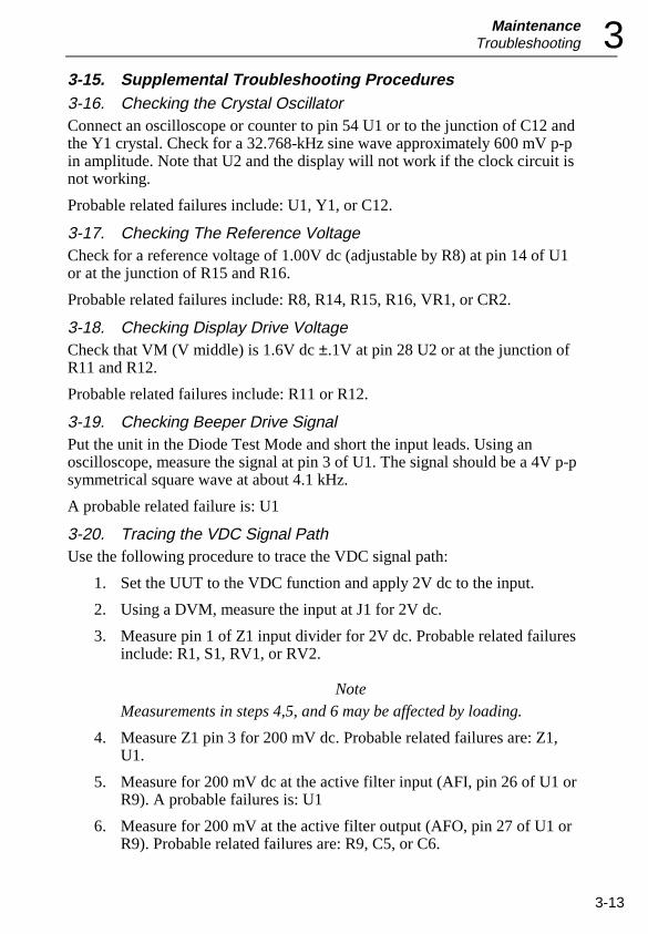
3-15. Supplemental Troubleshooting Procedures3-16. Checking the Crystal OscillatorConnect an oscilloscope or counter to pin 54 U1 or to the junction of C12 andthe Y1 crystal. Check for a 32.768-kHz sine wave approximately 600 mV p-pin amplitude. Note that U2 and the display will not work if the clock circuit isnot working.
Probable related failures include: U1, Y1, or C12.
3-17. Checking The Reference VoltageCheck for a reference voltage of 1.00V dc (adjustable by R8) at pin 14 of U1or at the junction of R15 and R16.
Probable related failures include: R8, R14, R15, R16, VR1, or CR2.
3-18. Checking Display Drive VoltageCheck that VM (V middle) is 1.6V dc ±.1V at pin 28 U2 or at the junction ofR11 and R12.
Probable related failures include: R11 or R12.
3-19. Checking Beeper Drive SignalPut the unit in the Diode Test Mode and short the input leads. Using anoscilloscope, measure the signal at pin 3 of U1. The signal should be a 4V p-psymmetrical square wave at about 4.1 kHz.
A probable related failure is: U1
3-20. Tracing the VDC Signal PathUse the following procedure to trace the VDC signal path:
1. Set the UUT to the VDC function and apply 2V dc to the input.
2. Using a DVM, measure the input at J1 for 2V dc.
3. Measure pin 1 of Z1 input divider for 2V dc. Probable related failuresinclude: R1, S1, RV1, or RV2.
Note Measurements in steps 4,5, and 6 may be affected by loading.
4. Measure Z1 pin 3 for 200 mV dc. Probable related failures are: Z1,U1.
5. Measure for 200 mV dc at the active filter input (AFI, pin 26 of U1 orR9). A probable failures is: U1
6. Measure for 200 mV at the active filter output (AFO, pin 27 of U1 orR9). Probable related failures are: R9, C5, or C6.

77 Series IIIService Manual
3-14
Static Awareness -1
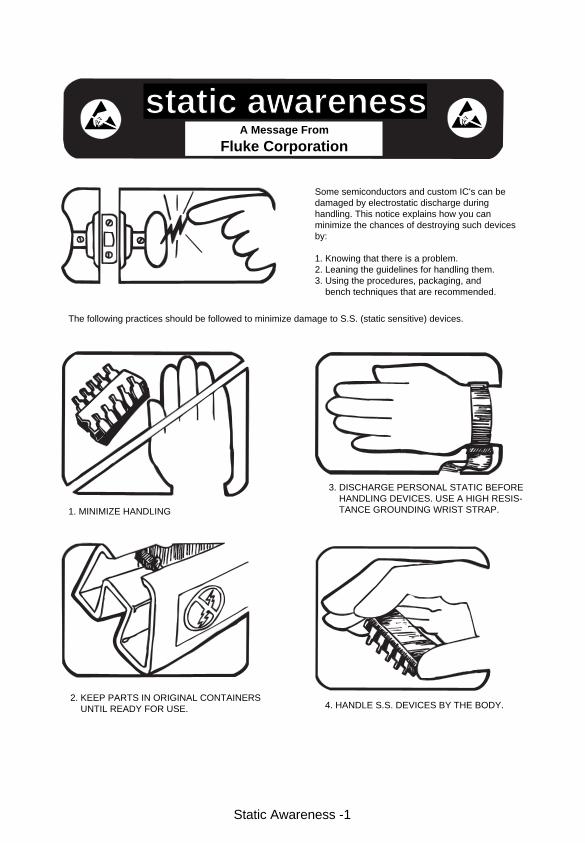
Some semiconductors and custom IC's can bedamaged by electrostatic discharge duringhandling. This notice explains how you canminimize the chances of destroying such devicesby:
1. Knowing that there is a problem.2. Leaning the guidelines for handling them.3. Using the procedures, packaging, and bench techniques that are recommended.
The following practices should be followed to minimize damage to S.S. (static sensitive) devices.
1. MINIMIZE HANDLING
2. KEEP PARTS IN ORIGINAL CONTAINERS UNTIL READY FOR USE.
3. DISCHARGE PERSONAL STATIC BEFORE HANDLING DEVICES. USE A HIGH RESIS- TANCE GROUNDING WRIST STRAP.
4. HANDLE S.S. DEVICES BY THE BODY.
static awarenessA Message From
Fluke Corporation
Static Awareness-2
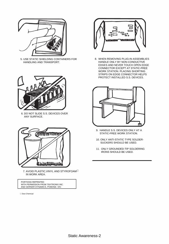
5. USE STATIC SHIELDING CONTAINERS FOR HANDLING AND TRANSPORT.
6. DO NOT SLIDE S.S. DEVICES OVER ANY SURFACE.
7. AVOID PLASTIC,VINYL AND STYROFOAM IN WORK AREA.
8. WHEN REMOVING PLUG-IN ASSEMBLIES HANDLE ONLY BY NON-CONDUCTIVE EDGES AND NEVER TOUCH OPEN EDGE CONNECTOR EXCEPT AT STATIC-FREE WORK STATION. PLACING SHORTING STRIPS ON EDGE CONNECTOR HELPS PROTECT INSTALLED S.S. DEVICES.
9. HANDLE S.S. DEVICES ONLY AT A STATIC-FREE WORK STATION.
10. ONLY ANTI-STATIC TYPE SOLDER- SUCKERS SHOULD BE USED.
11. ONLY GROUNDED-TIP SOLDERING IRONS SHOULD BE USED.
PORTIONS REPRINTEDWITH PERMISSION FROM TEKTRONIX INC.AND GERNER DYNAMICS, POMONA DIV.
Dow Chemical
4-1
Chapter 4List of Replaceable Parts
Contents Page
4-1. Introduction..................................................................... 4-34-2. How to Obtain Parts........................................................ 4-34-3. Newer Instruments .......................................................... 4-34-4. Service Centers ............................................................... 4-34-5. Manual Status Information ............................................. 4-44-6. Parts Lists........................................................................ 4-4

77 Series IIIService Manual
4-2
List of Replaceable PartsIntroduction 4
4-3
4-1. IntroductionThis section contains an illustrated list of replaceable parts for 77 Series IIIMultimeter.
4-2. How to Obtain PartsElectrical components may be ordered directly from the Fluke Corporationand its authorized representatives by using the part number under the headingFLUKE PN. In the U.S., order directly from the Fluke Parts Dept. by calling1-800-526-4731. Parts price information is available from the FlukeCorporation or its representatives. Prices are also available in a FlukeReplacement Parts Catalog which is available on request.
In the event that the part ordered has been replaced by a new or improved part,the replacement will be accompanied by an explanatory note and installationinstructions, if necessary.
To ensure prompt delivery of the correct part, include the followinginformation when you place an order:
• Part number and revision level of the pca containing the part.• Reference designator• Fluke stock number• Description (as given under the DESCRIPTION heading)• Quantity• Instrument Model, Serial Number, and Firmware Numbers
4-3. Newer InstrumentsChanges and improvements made to the instrument are identified byincrementing the revision letter marked on the affected pca. These changes aredocumented on a manual supplement which, when applicable, is included withthe manual.
4-4. Service CentersTo locate an authorized service center, call Fluke using any of the phonenumbers listed below, or visit us on the World Wide Web: www.fluke.com
USA: 1-888-99-FLUKE (1-888-993-5853)Canada: 1-800-36-FLUKE (1-800-363-5853)Europe: +31 402-678-200Japan: +81-3-3434-0181Singapore: +65-738-5655Anywhere in the world: +1-425-446-5500
77 Series IIIService Manual
4-4
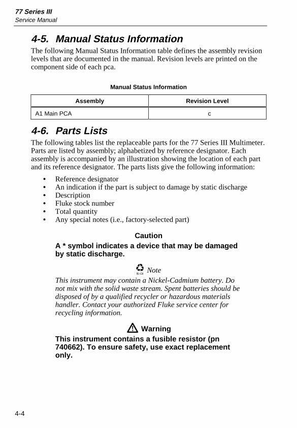
4-5. Manual Status InformationThe following Manual Status Information table defines the assembly revisionlevels that are documented in the manual. Revision levels are printed on thecomponent side of each pca.
Manual Status Information
Assembly Revision Level
A1 Main PCA c
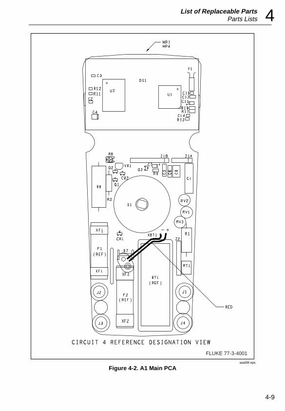
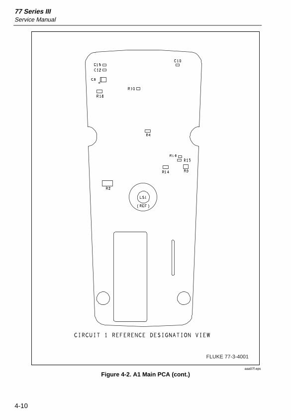
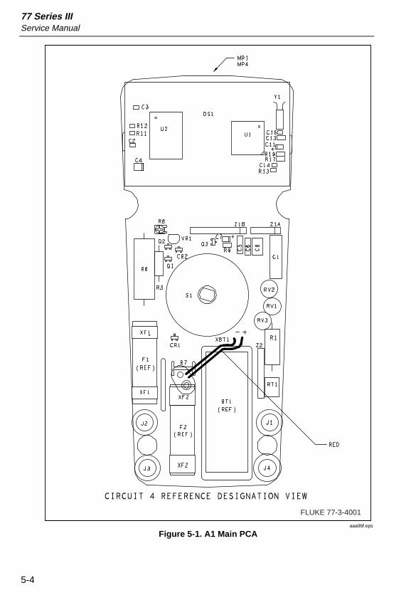
4-6. Parts ListsThe following tables list the replaceable parts for the 77 Series III Multimeter.Parts are listed by assembly; alphabetized by reference designator. Eachassembly is accompanied by an illustration showing the location of each partand its reference designator. The parts lists give the following information:
• Reference designator• An indication if the part is subject to damage by static discharge• Description• Fluke stock number• Total quantity• Any special notes (i.e., factory-selected part)
CautionA * symbol indicates a device that may be damagedby static discharge.
NoteThis instrument may contain a Nickel-Cadmium battery. Donot mix with the solid waste stream. Spent batteries should bedisposed of by a qualified recycler or hazardous materialshandler. Contact your authorized Fluke service center forrecycling information.
WarningThis instrument contains a fusible resistor (pn740662). To ensure safety, use exact replacementonly.
List of Replaceable PartsParts Lists 4
4-5
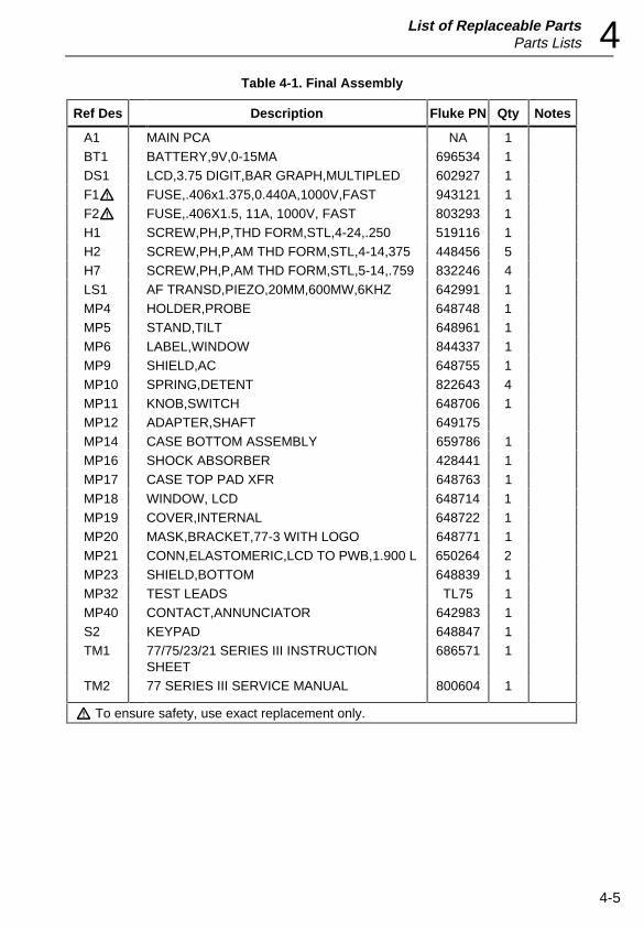
Table 4-1. Final Assembly
Ref Des Description Fluke PN Qty Notes
A1 MAIN PCA NA 1BT1 BATTERY,9V,0-15MA 696534 1DS1 LCD,3.75 DIGIT,BAR GRAPH,MULTIPLED 602927 1F1W FUSE,.406x1.375,0.440A,1000V,FAST 943121 1F2W FUSE,.406X1.5, 11A, 1000V, FAST 803293 1H1 SCREW,PH,P,THD FORM,STL,4-24,.250 519116 1H2 SCREW,PH,P,AM THD FORM,STL,4-14,375 448456 5H7 SCREW,PH,P,AM THD FORM,STL,5-14,.759 832246 4LS1 AF TRANSD,PIEZO,20MM,600MW,6KHZ 642991 1MP4 HOLDER,PROBE 648748 1MP5 STAND,TILT 648961 1MP6 LABEL,WINDOW 844337 1MP9 SHIELD,AC 648755 1MP10 SPRING,DETENT 822643 4MP11 KNOB,SWITCH 648706 1MP12 ADAPTER,SHAFT 649175MP14 CASE BOTTOM ASSEMBLY 659786 1MP16 SHOCK ABSORBER 428441 1MP17 CASE TOP PAD XFR 648763 1
MP18 WINDOW, LCD 648714 1MP19 COVER,INTERNAL 648722 1MP20 MASK,BRACKET,77-3 WITH LOGO 648771 1MP21 CONN,ELASTOMERIC,LCD TO PWB,1.900 L 650264 2MP23 SHIELD,BOTTOM 648839 1MP32 TEST LEADS TL75 1MP40 CONTACT,ANNUNCIATOR 642983 1S2 KEYPAD 648847 1TM1 77/75/23/21 SERIES III INSTRUCTION
SHEET686571 1
TM2 77 SERIES III SERVICE MANUAL 800604 1
W To ensure safety, use exact replacement only.
77 Series IIIService Manual
4-6
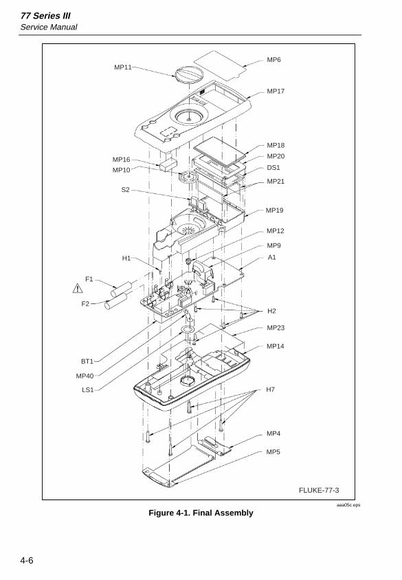
MP6
MP17
MP18
MP20
DS1
MP21
MP19
MP12
MP9
A1
H2
MP23
MP14
H7
MP4
MP5
MP11
MP16
MP10
S2
H1
F1
F2
BT1
MP40
LS1
FLUKE-77-3
aaa05c.eps
Figure 4-1. Final Assembly
List of Replaceable PartsParts Lists 4
4-7
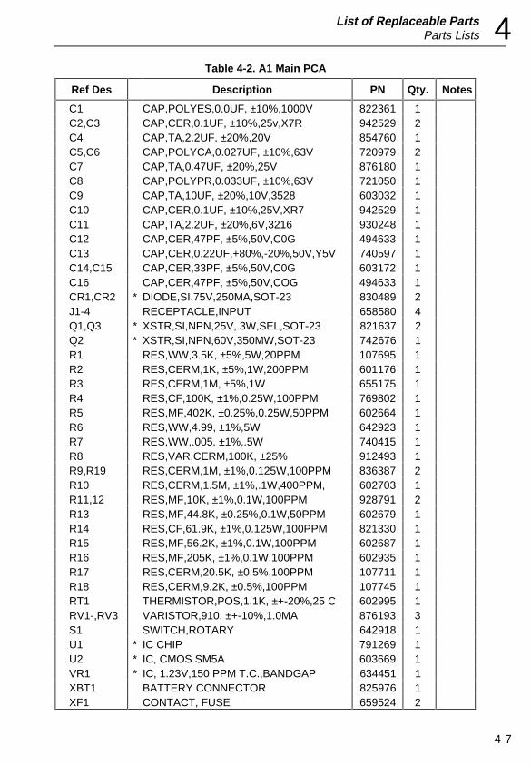
Table 4-2. A1 Main PCA
Ref Des Description PN Qty. Notes
C1 CAP,POLYES,0.0UF, ±10%,1000V 822361 1C2,C3 CAP,CER,0.1UF, ±10%,25v,X7R 942529 2C4 CAP,TA,2.2UF, ±20%,20V 854760 1C5,C6 CAP,POLYCA,0.027UF, ±10%,63V 720979 2C7 CAP,TA,0.47UF, ±20%,25V 876180 1C8 CAP,POLYPR,0.033UF, ±10%,63V 721050 1C9 CAP,TA,10UF, ±20%,10V,3528 603032 1C10 CAP,CER,0.1UF, ±10%,25V,XR7 942529 1C11 CAP,TA,2.2UF, ±20%,6V,3216 930248 1C12 CAP,CER,47PF, ±5%,50V,C0G 494633 1C13 CAP,CER,0.22UF,+80%,-20%,50V,Y5V 740597 1C14,C15 CAP,CER,33PF, ±5%,50V,C0G 603172 1C16 CAP,CER,47PF, ±5%,50V,COG 494633 1CR1,CR2 * DIODE,SI,75V,250MA,SOT-23 830489 2J1-4 RECEPTACLE,INPUT 658580 4Q1,Q3 * XSTR,SI,NPN,25V,.3W,SEL,SOT-23 821637 2Q2 * XSTR,SI,NPN,60V,350MW,SOT-23 742676 1R1 RES,WW,3.5K, ±5%,5W,20PPM 107695 1R2 RES,CERM,1K, ±5%,1W,200PPM 601176 1R3 RES,CERM,1M, ±5%,1W 655175 1R4 RES,CF,100K, ±1%,0.25W,100PPM 769802 1R5 RES,MF,402K, ±0.25%,0.25W,50PPM 602664 1R6 RES,WW,4.99, ±1%,5W 642923 1R7 RES,WW,.005, ±1%,.5W 740415 1R8 RES,VAR,CERM,100K, ±25% 912493 1R9,R19 RES,CERM,1M, ±1%,0.125W,100PPM 836387 2R10 RES,CERM,1.5M, ±1%,.1W,400PPM, 602703 1R11,12 RES,MF,10K, ±1%,0.1W,100PPM 928791 2R13 RES,MF,44.8K, ±0.25%,0.1W,50PPM 602679 1R14 RES,CF,61.9K, ±1%,0.125W,100PPM 821330 1R15 RES,MF,56.2K, ±1%,0.1W,100PPM 602687 1R16 RES,MF,205K, ±1%,0.1W,100PPM 602935 1R17 RES,CERM,20.5K, ±0.5%,100PPM 107711 1R18 RES,CERM,9.2K, ±0.5%,100PPM 107745 1RT1 THERMISTOR,POS,1.1K, ±+-20%,25 C 602995 1RV1-,RV3 VARISTOR,910, ±+-10%,1.0MA 876193 3S1 SWITCH,ROTARY 642918 1U1 * IC CHIP 791269 1U2 * IC, CMOS SM5A 603669 1VR1 * IC, 1.23V,150 PPM T.C.,BANDGAP 634451 1XBT1 BATTERY CONNECTOR 825976 1XF1 CONTACT, FUSE 659524 2
77 Series IIIService Manual
4-8
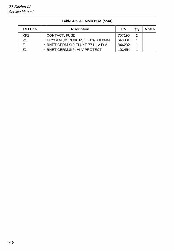
Table 4-2. A1 Main PCA (cont)
Ref Des Description PN Qty. Notes
XF2 CONTACT, FUSE 707190 2Y1 CRYSTAL,32.768KHZ, ±+-1%,3 X 8MM 643031 1Z1 * RNET,CERM,SIP,FLUKE 77 HI V DIV. 946202 1Z2 * RNET,CERM,SIP, HI V PROTECT 103454 1
List of Replaceable PartsParts Lists 4
4-9
FLUKE 77-3-4001
aaa06f.eps
Figure 4-2. A1 Main PCA
77 Series IIIService Manual
4-10
FLUKE 77-3-4001
aaa07f.eps
Figure 4-2. A1 Main PCA (cont.)

5-1
Chapter 5Schematic Diagrams

77 Series IIIService Manual
5-2
Schematic Diagrams 5
5-3
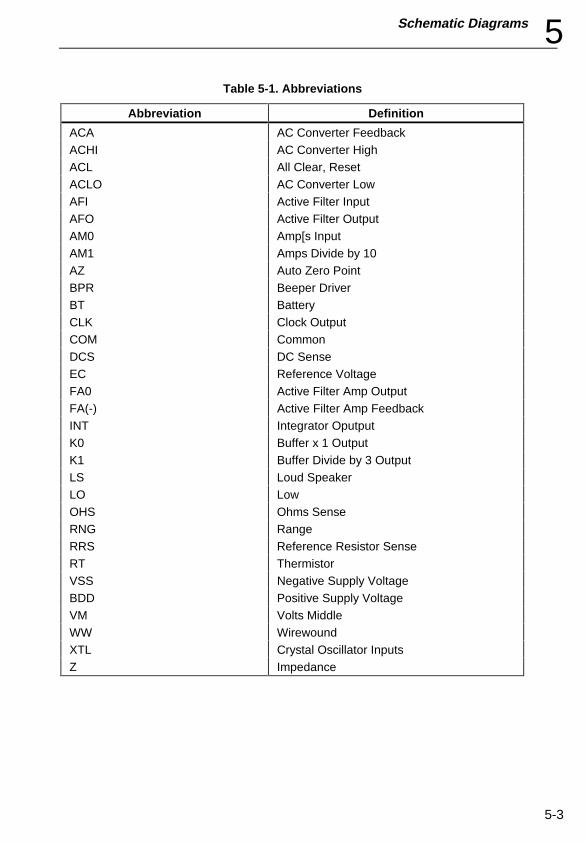
Table 5-1. Abbreviations
Abbreviation Definition
ACA AC Converter FeedbackACHI AC Converter HighACL All Clear, ResetACLO AC Converter LowAFI Active Filter InputAFO Active Filter OutputAM0 Amp[s InputAM1 Amps Divide by 10AZ Auto Zero PointBPR Beeper DriverBT BatteryCLK Clock OutputCOM CommonDCS DC SenseEC Reference VoltageFA0 Active Filter Amp OutputFA(-) Active Filter Amp FeedbackINT Integrator OputputK0 Buffer x 1 OutputK1 Buffer Divide by 3 OutputLS Loud SpeakerLO LowOHS Ohms SenseRNG RangeRRS Reference Resistor SenseRT ThermistorVSS Negative Supply VoltageBDD Positive Supply VoltageVM Volts MiddleWW WirewoundXTL Crystal Oscillator InputsZ Impedance
77 Series IIIService Manual
5-4
FLUKE 77-3-4001
aaa06f.eps
Figure 5-1. A1 Main PCA
Schematic Diagrams 5
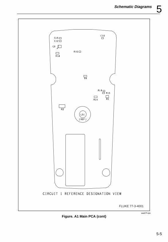
5-5
FLUKE 77-3-4001
aaa07f.eps
Figure. A1 Main PCA (cont)
77 Series IIIService Manual
5-6
CW
R8100K
300MA
GUARDGUARD
OHS
GUARD
V0GUARD
GUARD
GUARD
V1
V4
GUARDV2
V3
RRS
DCS
AM0
AMI
GUARD
GUARD
GUARD
MV
C O M
LO
S1
1 2
10M
Z1
7
3
4
5
6
1.0K
10K
101K
1.1MZ1
R13.5K
Z2 1.0M
RV2910V
RV1910V
COM
J4
J3
J2
J1
VR1
205KR16
11A FASTF2
.005R7
44/100A FASTF1
4.99R6
R5402K
S1
BAS16CR2
56.2KR15
61.9KR14
VDD
Q3SEL
Q2MMBT3904
SELQ1
S1
R13
44.8K
R3 1.0M
RT11.1K C1
0.01
S1
R4 100K
33PFC14
R21.0K
RV3910V
NOT USEDUSEDLAST
REFERENCE DESIGNATON
Z2
Y1
VR1
U2
TP2TP3
S3
RV3
RT1
R2R19
Q3
LS1
J4
F2
DS1
CR2
C15
BT1
VAC,VDC
OHMS,VDC,MVDC
OHMS,DTCONT,MVDC
10A
C O M M O N
MA
VOLTS/OHMS
OHMS,DT,CONT
2.7VCAL
1.5MM
1MM
5%
25%
1.23V
0.1W
0.1W
1%
0.25%
0.5WW W
MF1000V
1000V
5%
1W
0.25W
5WW W
1%
5%
5%
1000VM
6MM
6MM
6MM 4MM
2MM
5WW W
MF
0.1W
0.25%
2 M M
1000V
20%
1
34
2 25
13
41
43
22
24
29
12
42
31
33
36
35
37
18
34
32
30
2111
2010
199
15
32
12
8
7
11 10
2MM
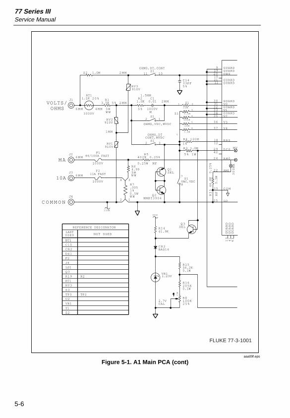
FLUKE 77-3-1001
aaa09f.eps
Figure 5-1. A1 Main PCA (cont)
Schematic Diagrams 5
5-7
0.22C13
VDDBT19V
1000V,300
CODEFUNCTION
INT
INTLOW
HIGH
MA,10A
INT
K0
AZ
K1
AFO
FAO
CONVERTER
FA(-)
AFI
ACLO
ACHI
ACA
B3
B1
B2
B0
+VDD
TEST
-VSS
BPR
XTAL2
XTAL1
ANALOGPROCESSOR
FILTER*
AC
ACAC
AC*
AC*
AC
MOHMS
3V,300K
30V,30K
300V,3K
SOURCEVOLTAGEOHMS
OHMS
DT,OHMSV
X1
X0.3
ACTIVEFILTER INTEGRATOR
TODIGITAL
SECTION
COMPARATOR
BUFFER
D3
D2
D1
D0
C0
NDAV
CLK
C1
C2
C3
EC
OHMSDE-INT
DE-INT
AP75
U1
47PFC16
TP1
10C9
9.20KR18
32.768KHZY1
47PFC12
33PFC15
.027
C6
20.5K
R17
.027C5
R101.50M
R9
1.00M
10
110K
225K
9
8
Z1
.033C8
1.00M
R19
0.47C7
S1
2.2
C11
S1 S1
LS1
CR1BAS16
S1
ON
RANGE
20%
63VPC
63VPC
PP
0.1W
25V
10V
0.5%
5%5%
63V
6V
0.5%
5%
58
14
57
4567
49
50
51
52
56
54 55 32 48 8
1716 26 4645443928 2740 47
59
1
60
12
6
4
6
5
6
9 6
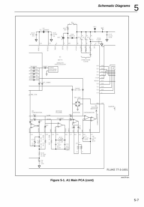
FLUKE 77-3-1001
aaa10f.eps
Figure 5-1. A1 Main PCA (cont)
77 Series IIIService Manual
5-8
TP3
HOLDHV
BT
DCK M
+/-AC
1D
1E
1A
2D
2E
2A
2B
3B
3A
3E
3D
MAN
4C4A
AUTO
BG1
BG5
BG3
BG9
BG7
BG11
BG13
BG15
BG17
BG19
BG21
BG25
BG23
BG29
BG27
BG31
H0
H1LCD-PANTHER
DS1
VM
VDD
VDD
P23
S3
S2
S1
S0
P22
P03P10
P01
P11
P02
P12
P20P13
P21
S7
S6
S5
S8
S4
S9
S11
S12
S10
S13
S14
S18
S17
S16
S15
S19
S20
S23
S22
S21
P00
INTA
RESETCK2
TF
DDC
OSCIN T1
OSCOUT T2
VCC
S24
S27
S26
S25
S28
S29
S33
S31
S32
S30
S34
S37
S39
S36
S35
S38
S40
S41
GND
H1H 0
GND
SMN3
U2
S3
R1210.0K
R1110.0K
VDD
0.1C2
0.1C10
0.1C3
2.2C4
S2
CER DESIGNATES CERAMIC CAPACITORM DESIGNATES MYLAR/POLYESTER FILM CAPACITOR
CERM DESIGNATES CERMET FILM RESISTORMF DESIGNATES METAL FILM RESISTORMG DESIGNATES METAL GLAZE RESISTORWW DESIGNATES WIRE WOUND RESISTOR
TA DESIGNATES TANTALUM CAPACITORPP DESIGNATES POLYPROPYLENE CAPACITORPC DESIGNATES POLYCARBONATE CAPACITOR
0=COMMON *1=VDD
CODE* FUNCTION
S1 POSITIONS PROCEDING CLOCKWISE
FUNCTION B0 B1 B2
1 OFF - - -2 AC VOLTS 1 1 13 DC VOLTS 0 1 14 300 MVDC 0 0 0
8 DC CURRENT 0 1 07 AC CURRENT 1 1 0
5 OHMS 0 0 16 DIODE TEST/CONTINUITY 1 0 0
HOLD
25V
25V
25V
0.1W 0.1W 37
36
40
2 19
21
39
24
25
27
28
29
30
34
35
33
32
38
26
22
3 54 76 8 10
9 11
12 13
15
14
41
42
17
16
18
20
23
31
72
74
73
32
36
37
35
34
30
79
7877
20
2
17161514131211109
76
8
60
26
185
31
33
58
57
38
59
49
5051
53
52
54
55
56
27
63
28
29
39
34
25
23
24
80
43
42
44
45
46
48
47
64
65
66
68
67
69
7071
19
22
2
1
1
2
20V
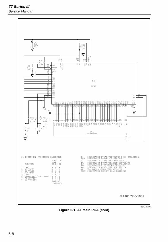
FLUKE 77-3-1001
aaa11f.eps
Figure 5-1. A1 Main PCA (cont)