76 the open mechanical engineering journal, open access …€¦ · · 2017-04-07and experiments....
TRANSCRIPT

Send Orders for Reprints [email protected]
76 The Open Mechanical Engineering Journal, 2013, 7, 76-82
1874-155X /13 2013 Bentham Open
Open Access
Study on the Pressure and Temperature Distribution of Solid-Plug Conveying Element on Centrifugal Extruder
Zhao Jing*,1
, Wang Jing2 and Wang Shijie
1
1School of Mechanical Engineering, Shenyang University of Technology, Shenyang, Liaoning, 110870, P.R. China
2School of Mechanical Engineering, Beijing University of Chemical Technology, Beijing, 100029, P.R. China
Abstract: In this paper, a new polymer processing machine--- centrifugal extruder is introduced. The pressure and
temperature distribution of centrifugal extruder have been studied by theoretical analysis, which is based on mathematics
and experiments. The results show that the pressure and temperature Distribution can provide the processing of solid-plug
conveying sufficiently and stably, which can prove the industry practicability of centrifugal extruder.
Keywords: Solid-plug conveying, centrifugal extruder, polymer process, mathematics analysis.
1. INTRODUCTION
Centrifugal extruder is a new polymer process machine. Compared with conventional extrusion equipment, centrifugal extruder has some advantages of building stabilized conveying pressure, energy consumption and good mixing, etc.
There were some inventions related to centrifugal extrusion, such as United States Patent No. 3,358,323
[1],
United States Patent No. 3,409,712 [2] etc. [3-6]. It was an
object of these inventions to provide some centrifugal apparatus for the preparation of granules. But no paper or literature has been published about the industry application of the equipments, which had been mentioned in these patents.
In this paper, the aim is to provide a centrifugal apparatus, which can be applied in the industry. And, to further provide a means to develop the pressure sufficiently to extrude plastic resinous material without employing conventional extrusion equipment.
2. OPERATION PRINCIPLE OF CENTRIFUGAL EX-TRUDER
Different from conventional extrusion equipment, the operation principle of centrifugal extruder is to employ the centrifugal force filed to develop stabilized conveying pressure. In Fig. (1), a partly-in-section view of the apparatus has illustrated.
The apparatus comprises two rotary parts, which are driven respectively by belt wheels 6 and 9 with the different rotary speed. Driven by the belt wheel 6, the rotary part comprises a rotor 1, a rotor 2 and a short screw 5, which is provided with two mechanical bearings (10)
*Address correspondence to this author at the School of Mechanical
Engineering, Shenyang University of Technology, Shenyang, Liaoning,
110870, P.R. China; Tel: +86 24 25496678; Fax: +86 24 25496271;
E-mail: [email protected]
Fig. (1). Centrifugal Extruder (General View).
secured to a support flame 11. Both of the front rotary parts are joined with bolts. The rotary part II driven by the belt wheel 9, comprises a rotor 3, the support of which means the same as the rotary part I.
The plastic resinous material, discharged into an opening 7, is pressed into a cavity 12 by its own-weight. Then, by the friction between the resinous material and the wall of the rotor 1, the plastic resinous material rotates with high velocity. It is well known that any rotary object must generate the centrifugal force. So, the plastic resinous material is pressed to the wall of the rotor 1 by the

Study on the Pressure and Temperature Distribution of Solid-Plug The Open Mechanical Engineering Journal, 2013, Volume 7 77
centrifugal force. In the centrifugal field, the higher the rotary velocity, the greater the pressure acting on the plastic resinous material. Thus it is clear that when the velocity gets to a certain value, the pressure can be built sufficiently and stably for the conveying of the material to the passageway 13. Here, it is a need to explain that in this phase the plastic resinous material has been the solid-plug form. Compared with the conventional extrusion process, the phase is defined as---the solid-plug conveying element.
Forced by the conveying pressure, the solid-plug in the passageway 13 enters in to a cavity 14. Due to the different velocity between the rotary part I and II, the plastic resinous material in the cavity 14, has to suffer the shearing force. This phase is called the shearing element. In the shearing element, the plastic resinous material completes further plastication and homogenization. According to the Weissenberg effect, the motion direction of the plastic resinous material is from the periphery of the cavity 14 to the center, which is similar to the motion of dish extruders. For further homogenization, the short screw 5 connected to the rotor 1 by a bolt is disposed in the center. At last, the plastic resinous material, which has been homogenized sufficiently, is extruded out through a die 17. We call this phase the homogenization element, just like the conventional extrusion process.
3. STUDY ON THE PRESSURE DISTRIBUTION OF SOLID-PLUG CONVEYING ELEMENT ON
CENTRIFUGAL EXTRUDER
3.1 Mathematical Model of The Pressure Distribution of
Solid-plug Conveying Element
For centrifugal extruder, the great difference from conventional screw extruder is the theory of solid-plug conveying. The solid-plug conveying of conventional screw extruder is based on the friction between the material and the barrel, or the screw, whereas the solid-plug conveying of centrifugal extruder is based on the centrifugal force field. In this paragraph, the solid-plug conveying theory of centrifugal extruder is studied by the mathematical analysis.
Firstly, the solid-plug conveying element of centrifugal extruder is simplified. The simplified constitution may be illustrated in Fig. (2), where, 1 is the rotor 1; 2 is the rotor 2; 3 is the cavity 12; 4 is the discharged barrel of the rotor1; 5 is an amplified solid-plug infinitesimal element.
Fig. (2), Simplified Constitution of Solid-plug Conveying Element.
For simplifying the mathematical analysis and calculation, we made some rational assumptions, which are given below:
1. The plastic resinous material discharged into the cavity 14, forms the solid-plug in the centrifugal force field, so the change of the material density may be neglected;
2. The solid-plug has a close contact with the wall of the rotor 1, and do not move relatively;
3. Thinking about the axial symmetry of the
mathematical model, in the cavity 14 the pressure
distribution of Pr is only the equation about the radius
r ;
4. The friction coefficient between the material and the wall of the rotor 1 is constant.
According to these assumptions, Fig. (3) illustrates every force which acted on the solid-plug conveying infinitesimal element. And based on the mass particle dynamics and D’Alembert’s principle, we define the rotor 1 as the reference coordinate system. In this coordinate system, all of the force which acted on the infinitesimal element is balanced in the radius direction.
Fig. (3). Every Force which Acted on the Solid-plug Conveying
Infinitesimal Element.
In Fig. (3), every symbol is expressed as follows:
B --- the width of the infinitesimal element;
h --- the height of the infinitesimal element;
RN ---the max radius of the cone (refer to Fig. 2);
F1 --- the force in the radius r , N;
F2 --- the force in the radius r + dr , N;
F3 --- the force on the in-wall of the rotor 1, N;
F4 --- the force on the up-wall of the rotor 2, N;
G --- the gravity of the infinitesimal element, N;
FTB --- the friction force on the in-wall of the rotor 1, N;
FTH --- the friction force on the up-wall of the rotor 2, N;
Fg ---the inertia force of the infinitesimal element from the
relative acceleration, N.
Some of them can be expressed by equations, as follows:
F1 = Pr RN r( ) B tan (1)
F2 = (Pr + dPr ) RN r dr( ) B tan (2)

78 The Open Mechanical Engineering Journal, 2013, Volume 7 Jing et al.
F3 = Prdr
cosB (3)
F4 = Pr B dr (4)
FTB = fB Pr Bdr
cos (5)
FTH = fH Pr B dr (6)
Fg = mae = m2r
=2 RN r( ) tan dr tan
2B dr 2r
(7)
G =2 RN r( ) tan dr tan
2B dr g (8)
ae =2r (9)
where,
Pr ---the pressure in the radius r Pa;
r ---the radius, m;
m ---the mass of the element, Kg ;
---the slope angle of the rotor 1, Degree;
Rn ---the max radius of the rotor 1, m ;
---the rotational speed of the rotor 1, minr ;
fB ---the friction coefficient between the material and the in-
wall of the rotor 1;
fH ---the friction coefficient between the material and the
up-wall of the rotor 2;
---the density of the plastic resinous material, Kg m3 ;
g --- the gravitational acceleration, m s2 .
According to the mass particle dynamics and D’Alembert’s principle, we define the rotor 1 as the reference coordinate system. In this coordinate system, all of the force which acted on the infinitesimal element is balanced in the radial direction. So, we can get the following equation:
F = 0 (10)
Use of Equation (1)-(10), we have:
F1 + Fg = F2 + F3 sin + FTB cos + FTH (11)
We put the expression of every force into Equation (11), and simply it. So we get:
Prr+ Pr
fH + fBRN r( ) tan
=2r (12)
The known boundary condition is: when r = r0 , Pr = P0 ,
where r0 is the radius of the discharged barrel of the rotor 1
(namely 4 in Fig. 2), and P0 is the pressure in the opening
discharged barrel of the rotor 1. solve Equation (12) and
consider the front boundary condition.
According to the mathematical calculation above, the
pressure distribution Pr is expressed as:
Pr =RN r( )
fH + fBtan
RN r0( )fH + fBtan
+
2 RN r( )fH + fBtan
1
2fH + fBtan
RN r( )2
fH + fBtan
RN
1fH + fBtan
RN r( )1
fH + fBtan
(13)
3.2. Experiment Correction of the Pressure Distribution of Solid-plug Conveying Element
In order to prove the rationality of the theoretical calculation, we designed an experimental equipment--- the solid-conveying experimental equipment. It is illustrated in Fig. (4).
The experimental equipment comprises a rotor, a Servo motor, a control system, a force sensor and a slip-ring. The assembling of the sensor1, the slip-rings 2 and the rotor 3 is shown in Fig. (5). The force sensor 1 is used to measure the pressure on the periphery of the rotor. The signal can be obtained by the slip-rings 2.
Fig. (4). Solid-plug Conveying Experimental Equipment.
In Table 1, Fth is the theory value of the solid-conveying pressure and Fexp is the experimental one. Referring to Table 1, it shows that Fth is close to Fexp, so it can prove that the mathematical analysis is currently reasonable. But it is seen that there is an amount of error between Fth and Fexp. The reason which leads to the error is that the density of the

Study on the Pressure and Temperature Distribution of Solid-Plug The Open Mechanical Engineering Journal, 2013, Volume 7 79
material resin changes with the pressure, and does not remain constant.
Fig. (5). Main Parts of Solid-plug Conveying Experimental
Equipment.
Table 1. Result of Experiments and Theory
( 1-1)
Rotation
Velocity (rpm) 500 600 700 800 900 1000
Fth (N) 1.568 2.254 3.067 4.008 5.067 6.252
Fexp (N) 1.274 1.960 2.842 3.626 4.608 5.880
(1-2)
Rotation
Velocity (rpm) 1100 1200 1300 1400 1500
Fth (N) 7.566 9.006 10.574 12.260 14.073
Fexp (N) 7.056 9.212 11.270 13.132 15.092
Using the mathematical software, the linear dependent relation of Fth and Fexp is achieved. And based on the relation, the theory analysis value of the solid-conveying pressure is corrected.
In Fig. (6), the linear dependent relation of Fth and Fexp can be described as:
Fexp=1.116Fth-0.786 (14)
In the mathematical analysis of the solid-conveying pressure, there must be some error in the theoretical value. Based on Equation (14), the corrected equation of the distribution of the solid-conveying pressure is achieved, which is as follows:
Prc = 1.116RN r( )
fH + fBtan
RN r0( )fH + fBtan
0.768Ss
(15)
where, Ss is the section area of the sensor.
Fig. (6). The Linear Dependent Relation of Fth and Fexp.
Based on the front analysis, we employ Mathcad --- a kind
of general mathematical software to calculate and make some
discussions on the influencing factors on the distribution of the
solid-conveying pressure. Then, the following can express some
operating conditions and some physical dimensions as:
= 5000 r min , RN = 0.2m , Rn = 0.19m , = 920kg / m3
(LDPE), = 56.8o , fH = fB = 0.3 . So the result of Equation
(15) is achieved, illustrated in Fig. (7).
According of Equation (15) and Fig. (7), the pressure of
the outlet (located at the edge of the rotor 1) can reach
2.25 106Pa . Thus it can be sure that centrifugal extruder
can provide the sufficient conveying pressure, which
provides the basis fortheory the industry feasibility of
centrifugal extruder.
Fig. (7). The Pressure Distribution of Solid-plug Conveying Phase.
According to the mathematical analysis and the solid conveying experiment, it can be proved that the centrifugal field can provide the solid-plug conveying pressure sufficiently and stably, which can prove the industry practicability of centrifugal extruder;
By the equation (15), the important influencing factors on
the pressure comprise the structural parameters of the rotor
1( , Rn ), the rotation velocity( n ), and the friction
coefficients of the rotors ( fH , fB )etc. The optimizing choice
0 2 4 6 8 10 12 14 160
2
4
6
8
10
12
14
16
Fe
xp
Fth
Fexp
=1.116Fth-0.786(N)
(N)
80 The Open Mechanical Engineering Journal, 2013, Volume 7 Jing et al.
of the influencing factors can efficiently increase the solid-
conveying pressure and at the same time can enhance the
solid-conveying efficiency.
4. STUDY ON THE TEMPERATURE DISTRIBUTION OF SOLID-PLUG CONVEYING ELEMENT ON
CENTRIFUGAL EXTRUDER
Two heating systems are applied on solid-plug phase of centrifugal extruder [7], referring to Fig. (8): 1) infrared radiation heating system and 2) electric conduction heating system. In this paper, the complex radiation heating system, primary heating system, is only studied.
Fig. (8). The Heating System of Solid Conveying Phase.
It includes three types of heating transformation methods: Conduction, Convection and Radiation, which seem to be complex for the analyses of heating transformation.
4.1. Mathematical Model of the Temperature Distribution of Solid-Plug Conveying Element
There are some assumptions:
(1) The surfaces of the rotor and the infrared heaters are grey-diffused surfaces. That is the absorbance of light spectrum is dependent on the light wavelength;
(2) If the rotor is fixed, it looks as if the air moves around the rotor;
(3) Ignore the inference of the air on the radiation, and the change of the air temperature.
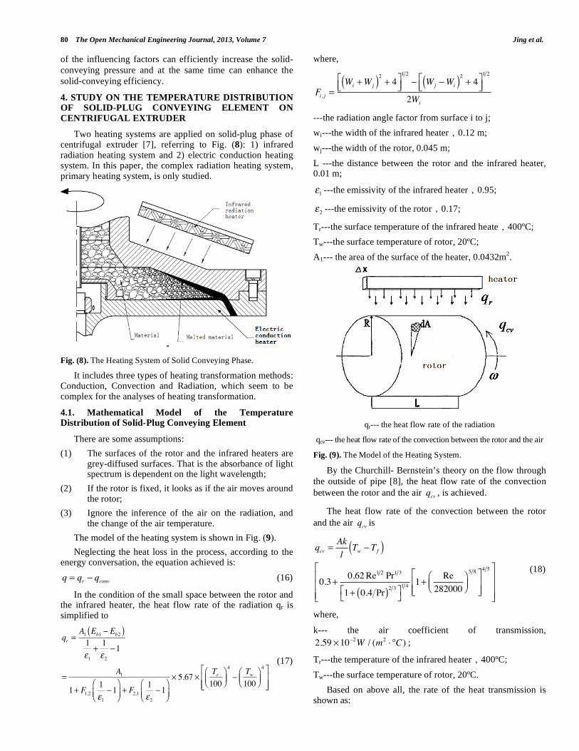
The model of the heating system is shown in Fig. (9).
Neglecting the heat loss in the process, according to the energy conversation, the equation achieved is:
q = qr qconv (16)
In the condition of the small space between the rotor and the infrared heater, the heat flow rate of the radiation qr is simplified to
qr =A1 Eb1 Eb2( )1
1
+1
2
1
=A1
1+ F1,21
1
1 + F2,11
2
1
5.67Tr100
4Tw100
4 (17)
where,
Fi, j =Wi +Wj( )
2+ 4
1 2
Wj Wi( )2+ 4
1 2
2Wi
---the radiation angle factor from surface i to j;
wi---the width of the infrared heater 0.12 m;
wj---the width of the rotor, 0.045 m;
L ---the distance between the rotor and the infrared heater, 0.01 m;
1 ---the emissivity of the infrared heater 0.95;
2 ---the emissivity of the rotor 0.17;
Tr---the surface temperature of the infrared heate 400ºC;
Tw---the surface temperature of rotor, 20ºC;
A1--- the area of the surface of the heater, 0.0432m2.
qr--- the heat flow rate of the radiation
qcv--- the heat flow rate of the convection between the rotor and the air
Fig. (9). The Model of the Heating System.
By the Churchill- Bernstein’s theory on the flow through
the outside of pipe [8], the heat flow rate of the convection
between the rotor and the air qcv , is achieved.
The heat flow rate of the convection between the rotor
and the air qcv is
qcv =Ak
lTw Tf( )
0.3+0.62Re1 2 Pr1 3
1+ 0.4 Pr( )2 3 1 4 1+
Re
282000
5 8 4 5 (18)
where,
k--- the air coefficient of transmission,
2.59 10 2W / (m2°C) ;
Tr---the temperature of the infrared heater 400ºC;
Tw---the surface temperature of rotor, 20ºC.
Based on above all, the rate of the heat transmission is shown as:

Study on the Pressure and Temperature Distribution of Solid-Plug The Open Mechanical Engineering Journal, 2013, Volume 7 81
q = qr qcv
=A1
1+ F1,21
1
1 + F2,11
2
1
5.67Tr100
4Tw100
4
Ak
lTw Tf( ) 0.3+
0.62Re1 2 Pr1 3
1+ 0.4 Pr( )2 3 1 4 1+
Re
282000
5 8 4 5
(19)
The rate of the heat transmission is known, so the change of the rotor temperature can be shown by the Fourier conduction theory :
T =A
A1
1+ F1,21
1
1 + F2,11
2
1
5.67Tr100
4Tw100
4
A
Ak
lTw Tf( ) 0.3+
0.62ud
v
1 2
Pr1 3
1+ 0.4 Pr( )2 3 1 4 1+
ud
v282000
5 8 4 5
(20)
where T is the change of the rotor temperature, °C .
If the shape of the rotor and the power of the infrared heater are determined, it is known from equation (20) that the change of the rotor temperature depends on the rotation speed of the rotor. Fig. (10) shows the relationship of the rotor temperature and rotation speed by equation (20).
Fig. (10). The Relationship of the Rotor Temperature and Rotation
Speed.
In Fig. (10), it is shown that the temperature of the
surface rotor decreases by the increasing rotation speed of
the rotor. The faster the rotation speed is, the lower the
temperature of the rotor surface. And, the temperature is
nearly constant by the higher rotation speed. However, when
the rotation speed is equal to zero, the rotor is in pre-heated
phase and the temperature is about 182°C.
4.2. Experiment of the Temperature Distribution of Solid-Plug Conveying Element
In order to prove the rationality of the above theoretical calculation, an experimental equipment is designed. It is illustrated in Fig. (11).
The parts of the experimental equipment include a rotor, a Servo motor, a control system. The temperature sensor is the infrared sensor in no-contact detection. And, there are six
infrared radiation heaters around the rotor shown in Fig. (12).
Fig. (11). The Experiment Equipment of Heating System,
Fig. (12). The Experiment Equipment of Heating System.
The important operation parameters of solid-conveying thermodynamic experimental equipment are:
1. the diameter of the rotor 3 is about 200 mm same as the one of the model machines of the centrifugal extruder;
2. the total height is about 550 mm.
3. the rotating-speed is 0~3000rpm, controllable;
4. the power of the Servo motor is 300W;
5. the power of six ceramic infrared heaters is 1200w total, 200w each;
6. the range of the infrared sensor is -32~545ºC.
In Fig. (13), the relationship of the rotation speed of the rotor and the temperature of the surface rotor in experiment is shown. It needs to be note that the temperature is in balance. In experiment, it is known that the temperature decrease by the increasing rotation speed. The experimental result is higher than the above theoretical result. The error is about 5%, so it approves that the theoretical model is rational.

82 The Open Mechanical Engineering Journal, 2013, Volume 7 Jing et al.
Fig. (13). The relationship of the rotation speed and the temperature
of the rotor surface in experiment.
In addition, the experiment for the time taken to get in balance is done. The temperature of the surface rotor begins to decrease with the experimental time, and at last the temperature goes to in balance. During the process, it takes about 22 minutes for different rotation speed. The temperature and time is shown in Fig. (14) in details.
Fig. (14). The curve on the time and the temperature of the rotor
surface in different rotor speed.
By the above research, the mathematical model of the thermodynamic on solid-plug conveying phase is built. And, the important equation of the temperature on the surface of the rotor is solved, equation (20). Fig. (10) shows the relationship of the rotor temperature and rotation speed, that in a certain work condition the temperature falls down with increasing the rotation speed. In addition, the temperature is nearly constant by the higher rotation speed and it balances.
By experiments, it is proved that the temperature falls down with the rotation speed increasing in a certain work condition fitting the mathematic result very well. But the mathematical result is larger than the experimental. It is because when working for some time, the temperature of the
air around the equipment lifts due to the radiation heating, and the influence of the convection transfer weakens.
In the same working condition, the rotor speed affects the temperature of the rotor surface, as the faster the speed, the lower the temperature and the loss of heat is more. So, in order to rate the heat transfer, it should increase the power of the radiation for the faster speed.
5. CONCLUSIONS
From the above-mentioned content, centrifugal extruder, a new polymer processing machine, is provided. And by the mathematical analysis and experiments, it is shown that the centrifugal force field can provide the solid-plug conveying pressure sufficiently and stably, which can prove the industrial practicability of centrifugal extruder. And the temperature distribution of solid-plug conveying phase is achieved in which the rotor speed affects the temperature of the rotor surface, as the faster the speed, the lower the temperature.
ABOUT THE AUTHORS
First Author Zhao Jing, University lecturer of Shenyang University of Technology, Ph.D. The author’s major is Fluid Machinery and Engineering. 16 papers received by EI or SCI and 2 patents had been published.
Second Author Wang Jing, master degree in engineering, studying for PhDs in Beijing University of Chemical Technology. The author’s major is Mechatronic Engineering.
Third Author Wang Shijie is a member of the IEEE and the IEEE Computer Society.
CONFLICT OF INTEREST
The author confirms that this article content has no conflict of interest.
ACKNOWLEDGEMENTS
This work was financially supported by the Liaoning Doctor Star-up Foundation (20111041).
REFERENCES
[1] Douglas s. Chisholm]. U.S Patent 3,358,323. 1967 [2] Douglas s. Chisholm. U.S Patent 3,483,281. 1969
[3] Douglas s. Chisholm. U.S Patent 3,912,799. 1975 [4] Douglas s. Chisholm. U.S Patent 3,409,712. 1968
[5] Masao Konishi. U.S Patent 6,783,708 B2. 2004 [6] Erich Lenk. U.S Patent 5,075,063. 1991
[7] J. Zhao, D. M. Wu, I.M.Kuzyayev, W. H. Chen, H. Xu and Y. Liu, “Study of Solid-plug Conveying in a Centrifugal Extruder”,
Journal of Polymer Processing Society, vol. 23, no. 3, pp. 286-297, 2008,.
[8] J. Zhao, X. L. LV and S. J. Wang, “Thermodynamic analyses of solid-plug conveying phase on centrifugal extruder”, Advanced
Materials Research, vol. 233, pp. 2279-2283, 2012.
Received: August 13, 2013 Revised: September 16, 2013 Accepted: October 3, 2013
© Jing et al.; Licensee Bentham Open.
This is an open access article licensed under the terms of the Creative Commons Attribution Non-Commercial License (http://creativecommons.org/licenses/by-nc/3.0/)
which permits unrestricted, non-commercial use, distribution and reproduction in any medium, provided the work is properly cited.