7.4 cables flexible cables and chains are used to support and transmit loads from one member to...
TRANSCRIPT

7.4 Cables7.4 Cables
Flexible cables and chains are used to support and transmit loads from one member to another
In suspension bridges and trolley wheels, they carry majority of the load
In force analysis, weight of cables is neglected as it is small compared to the overall weight
Consider three cases: cable subjected to concentrated loads, subjected to distributed load and subjected to its own weight

7.4 Cables7.4 Cables Assume that the cable is perfectly flexible
and inextensible Due to its flexibility, the cables offers no
resistance to bending and therefore, the tensile force acting in the cable is always tangent to the points along its length
Being inextensible, the length remains constant before and after loading, thus can be considered as a rigid body

7.4 Cables7.4 Cables
Cable Subjected to Concentrated Loads For a cable of negligible weight supporting
several concentrated loads, the cable takes the form of several straight line segments, each subjected to constant tensile force

7.4 Cables7.4 Cables
Cable Subjected to Concentrated Loads Known: h, L1, L2, L3 and loads P1 and P2
Form 2 equations of equilibrium at each point A, B, C and D
If the total length L is given, use Pythagorean Theorem to relate the three segmental lengths
If not, specify one of the sags, yC and yD
and from the answer, determine the other sag and hence, the total length L
7.4 Cables7.4 Cables
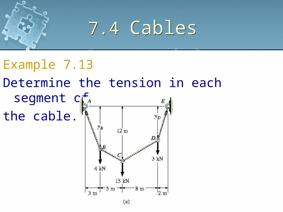
Example 7.13Determine the tension in each segment
of the cable.
7.4 Cables7.4 Cables
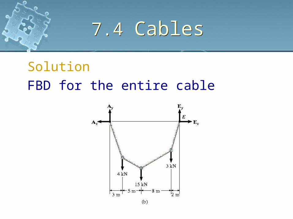
SolutionFBD for the entire cable

7.4 Cables7.4 Cables
Solution
kNE
EkNkNkNkN
F
kNA
mknmkNmkNmAM
EA
F
y
y
y
y
yE
xx
x
10
0315412
;0
12
0)2(3)10(15)15(4)18(;0
0
;0

7.4 Cables7.4 Cables
SolutionConsider leftmost
section which cuts cable BC since sag yC = 12m

7.4 Cables7.4 Cables
Solution
kNT
TkNkN
F
kNT
F
kNEA
mkNmkNmAM
BCBC
BCBC
y
BCBC
x
xx
xC
2.10,6.51
0sin412
;0
033.6cos
;0
33.6
0)5(4)8(12)12(;0

7.4 Cables7.4 Cables
SolutionConsider point A, C and E,
7.4 Cables7.4 Cables
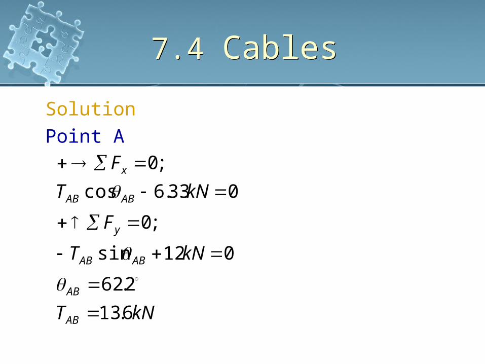
SolutionPoint A
kNT
kNT
F
kNT
F
AB
AB
ABAB
y
ABAB
x
6.13
2.62
012sin
;0
033.6cos
;0

7.4 Cables7.4 Cables
SolutionPoint C
kNT
kNkNT
F
kNT
F
CD
CD
CDCD
y
CDCD
x
44.9
9.47
0156.51sin2.10sin
;0
06.51cos2.10cos
;0

7.4 Cables7.4 Cables
SolutionPoint E
kNT
TkN
F
TkN
F
ED
ED
EDED
y
EDED
x
8.11
7.57
0sin10
;0
0cos33.6
;0
7.4 Cables7.4 Cables
Solution By comparison, maximum cable tension is
in segment AB since this segment has the greatest slope
For any left hand side segment, the horizontal component Tcosθ = Ax
Since the slope angles that the cable segment make with the horizontal have been determined, the sags yB and yD can be determined using trigonometry

7.4 Cables7.4 Cables
Cable Subjected to a Distributed LoadConsider weightless cable subjected to a
loading function w = w(x) measured in the x direction
7.4 Cables7.4 Cables
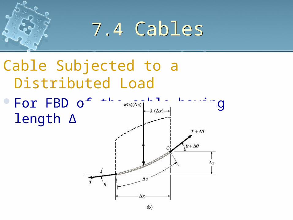
Cable Subjected to a Distributed Load
For FBD of the cable having length ∆

7.4 Cables7.4 Cables
Cable Subjected to a Distributed Load
Since the tensile force in the cable changes continuously in both the magnitude and the direction along the cable’s length, this change is denoted on the FBD by ∆T
Distributed load is represented by its resultant force w(x)(∆x) which acts a fractional distance k(∆x) from point O where o < k < 1
7.4 Cables7.4 Cables
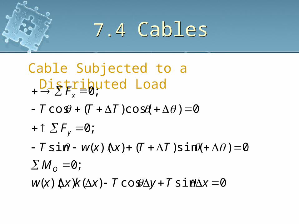
Cable Subjected to a Distributed Load
0sincos)())((
;0
0)sin()())((sin
;0
0)cos()(cos
;0
xTyTxkxxw
M
TTxxwT
F
TTT
F
O
y
x
7.4 Cables7.4 Cables
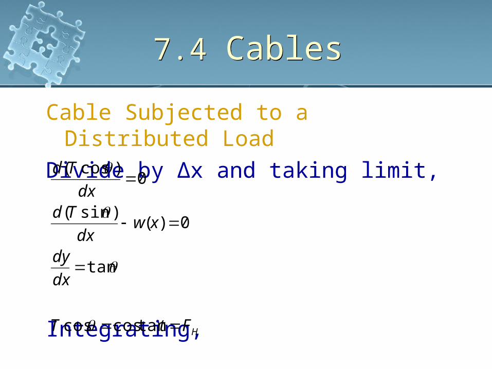
Cable Subjected to a Distributed Load
Divide by ∆x and taking limit,
Integrating, HFtT
dx
dy
xwdx
Tddx
Td
tancoscos
tan
0)()sin(
0)cos(

7.4 Cables7.4 Cables
Cable Subjected to a Distributed Load
Integrating,
Eliminating T,
Perform second integration,
dxdxxwF
y
dxxwFdx
dy
dxxwT
H
H
)(1
)(1
tan
)(sin

7.4 Cables7.4 Cables
Example 7.14The cable of a suspension bridge supports half of the uniform road surface between the two columns at A and B. If this distributed loading wo, determine
the maximum force developed in the cable and the cable’s required length. The span length L and, sag h are known.
7.4 Cables7.4 Cables
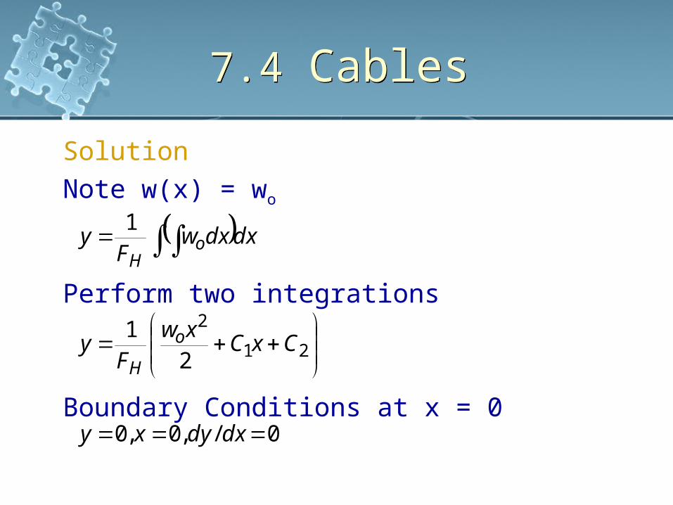
SolutionNote w(x) = wo
Perform two integrations
Boundary Conditions at x = 0
0/,0,0
21
1
21
2
dxdyxy
CxCxw
Fy
dxdxwF
y
o
H
oH

7.4 Cables7.4 Cables
SolutionTherefore,
Curve becomes
This is the equation of a parabola
Boundary Condition at x = L/2hy
xF
wy
CC
H
o
2
21
2
0

7.4 Cables7.4 Cables
SolutionFor constant,
Tension, T = FH/cosθ
Maximum tension occur at point B for 0 ≤ θ ≤ π/2
22
2
48
xL
hy
h
LwF oH

7.4 Cables7.4 CablesSolutionSlope at point B
Or
Therefore
Using triangular relationship
2
4
)cos(
2tan
tan
222
max
maxmax
1max
2/max
2/
LwFT
FT
FLw
Fw
dxdy
oH
H
H
o
LxH
o
Lx

7.4 Cables7.4 CablesSolution
For a differential segment of cable length ds
Determine total length by integrating
Integrating yields
Lh
hL
LhL
dxxL
hds
dxdxdy
dydxds
hLLw
T
L
o
4sinh
44
12
812
1
41
2
12
2/
0
2
2
222
2
max

7.4 Cables7.4 Cables
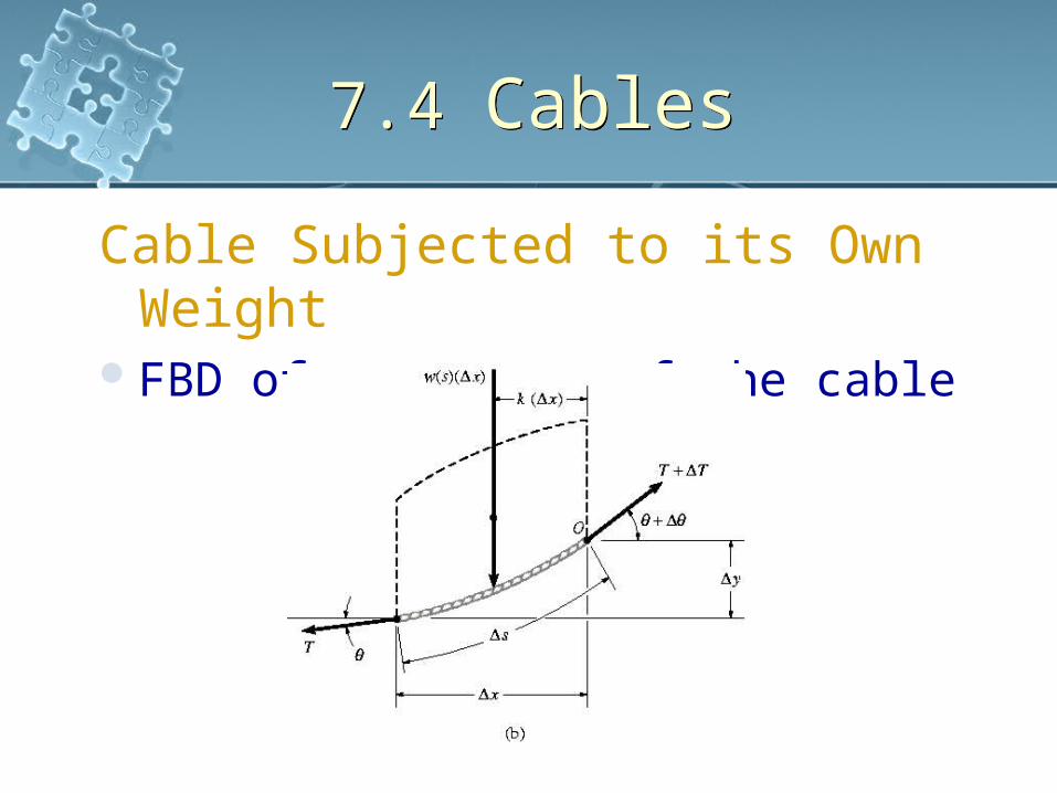
Cable Subjected to its Own WeightWhen weight of the cable is considered,
the loading function becomes a function of the arc length s rather than length x
For loading function w = w(s) acting along the cable,
7.4 Cables7.4 Cables
Cable Subjected to its Own Weight
FBD of a segment of the cable

7.4 Cables7.4 Cables
Cable Subjected to its Own Weight Apply equilibrium equations to the force
system
Replace dy/dx by ds/dx for direct integration
dsswFdx
dy
dsswT
FT
H
H
)(1
)(sin
cos

7.4 Cables7.4 Cables
Cable Subjected to its Own Weight
Therefore
Separating variables and integrating
2/12
2
2/12
2
2
22
)(1
1
)(1
1
1
dsswF
dsx
dsswFdx
ds
dxds
dxdy
dydxdsT
H
H

7.4 Cables7.4 Cables
Example 7.15Determine the deflection curve, the length, and the maximum tension in the uniform cable. The cable weights wo = 5N/m.

7.4 Cables7.4 Cables
Solution For symmetry, origin located at the
center of the cable Deflection curve expressed as y = f(x)
Integrating term in the denominator
2/121
2
2/122
/11
/11
CswF
dsx
dswF
dsx
oH
oH
7.4 Cables7.4 Cables
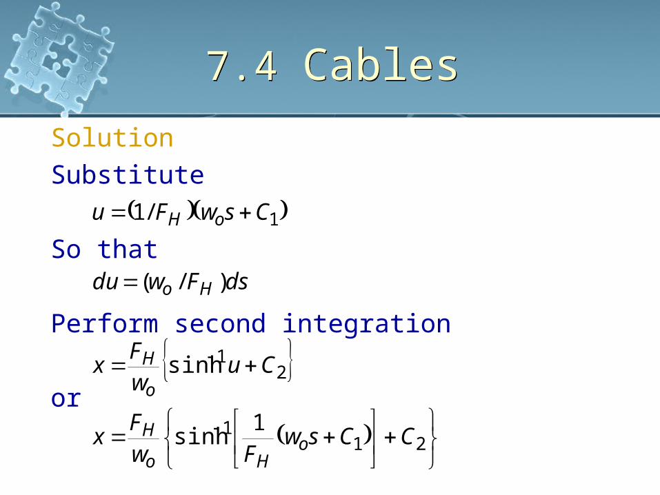
SolutionSubstitute
So that
Perform second integration
or
211
21
1
1sinh
sinh
)/(
/1
CCswFw
Fx
CuwF
x
dsFwdu
CswFu
oHo
H
o
H
Ho
oH

7.4 Cables7.4 CablesSolutionEvaluate constants
or
dy/dx = 0 at s = 0, then C1 = 0
To obtain deflection curve, solve for s
xFw
wF
s
CswFdx
dy
dswFdx
dy
H
o
o
H
oH
oH
sinh
1
1
1

7.4 Cables7.4 CablesSolution
Hence
Boundary Condition y = 0 at x = 0
For deflection curve,
This equations defines a catenary curve
1cosh
cosh
sinh
3
3
xF
w
w
Fy
w
FC
CxF
w
w
Fy
xF
w
dx
dy
H
o
o
H
o
H
H
o
o
H
H
o
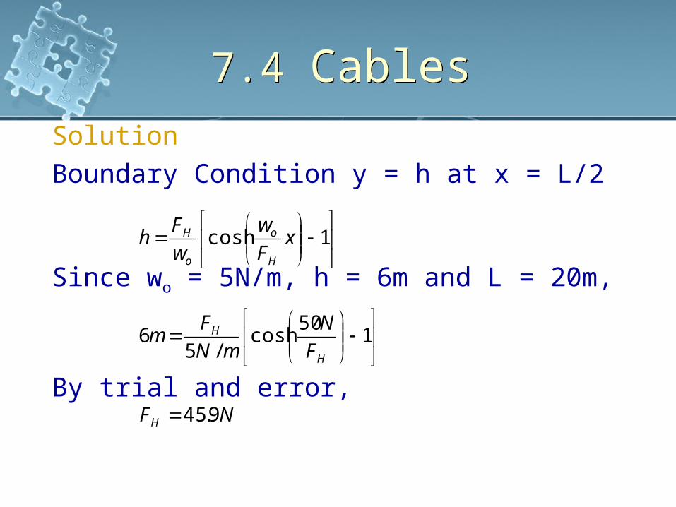
7.4 Cables7.4 CablesSolutionBoundary Condition y = h at x = L/2
Since wo = 5N/m, h = 6m and L = 20m,
By trial and error,NF
F
N
mN
Fm
xF
w
w
Fh
H
H
H
H
o
o
H
9.45
150
cosh/5
6
1cosh
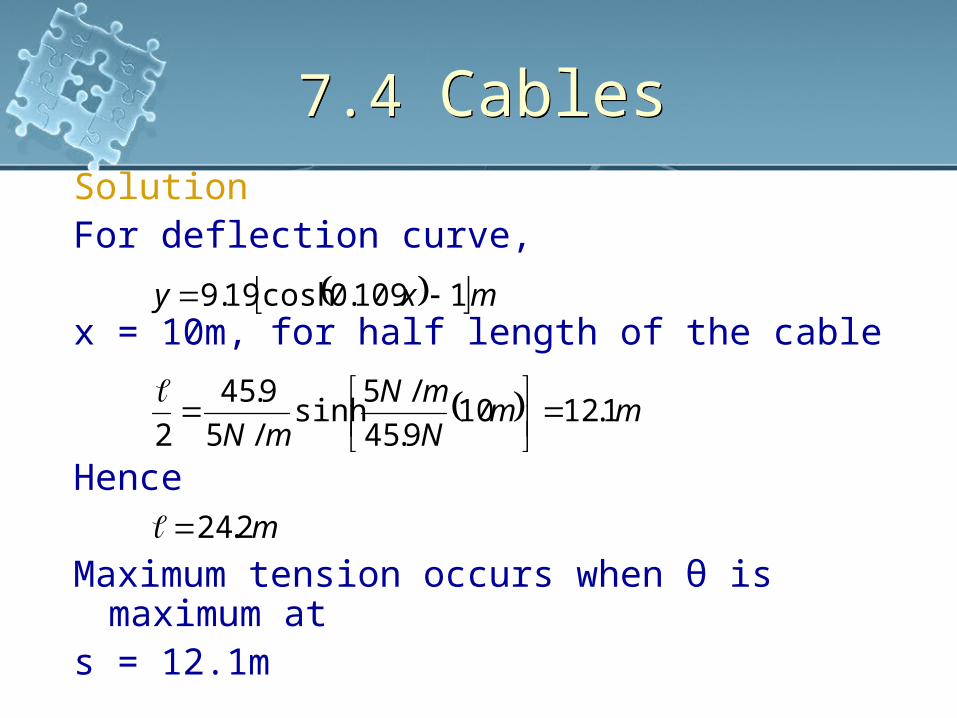
7.4 Cables7.4 CablesSolutionFor deflection curve,
x = 10m, for half length of the cable
Hence
Maximum tension occurs when θ is maximum at
s = 12.1m
m
mmN
mN
mN
mxy
2.24
1.12109.45
/5sinh
/5
9.45
2
1109.0cosh19.9

7.4 Cables7.4 CablesSolution
NNF
T
N
mmN
dx
dy
H
ms
9.758.52cos
9.45
cos
8.52
32.19.45
1.12/5tan
maxmax
max
max1.12

Chapter Summery Chapter Summery
Internal Loadings If a coplanar force system acts on a
member, then in general a resultant normal force N, shear force V and bending moment M will act at any cross-section along the member
These resultants are determined using the method of sections
The member is sectioned at the point where the internal loadings are to be determined

Chapter Summery Chapter Summery
Internal Loadings A FBD of one of the sectioned parts is
drawn The normal force is determined from the
summation of the forces normal to the cross-section
The shear force is determined from the summation of the forces tangent to the cross section
The bending moment is found from the summation of the moments about the centroid of the cross-sectional area
Chapter Summery Chapter Summery
Internal Loadings If the member is subjected to 3D
loading, in general, a torisonal loading will also act on the cross-section
It can be determined by the summation of the moments about an axis that is perpendicular to the cross section and passes through its centroid
Chapter Summery Chapter Summery
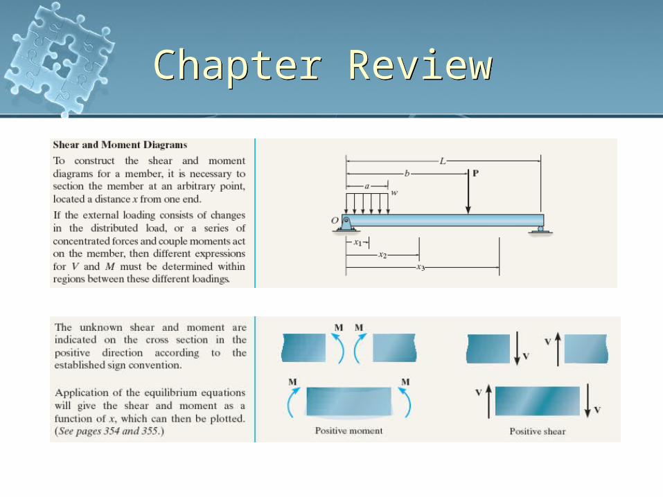
Shear and Moment Diagrams as Functions of x Section the member at an arbitrary point
located distance x from one end to construct the shear and moment diagrams for a member
Unknown shear and moment are indicated on the cross-section in the positive direction according to the established sign convention
Applications of the equilibrium equations will make these loadings functions of x which then, can be plotted

Chapter Summery Chapter Summery
Shear and Moment Diagrams as Functions of x If the external loadings or concentrated
forces and couple moments act on the member, then different expressions of V and M must be determined within regions between these regions
Graphical Methods for Establishing Shear and Moment Diagrams Plot the shear and moment diagrams using
differential relationships that exist between the distributed loading w and V and M
Chapter Summery Chapter Summery
Graphical Methods for Establishing Shear and Moment Diagrams Slope of the shear diagram = distributed
loading at any pointdV/dx = -w
Slope of the moment diagram = shear at any point
V = dM/dx Change in shear between an y two points
= area under the shear diagram between points, ∆M = ∫Vdx
Chapter Summery Chapter Summery
Cables When a flexible and inextensible cable is
subjected to a series of concentrated forces, the analysis of the cable can be performed by using the equations of equilibrium applied to the FBD of wither segments or points of application of the loading
If the external distributed loads or weight of the cables are considered, forces and shape of the cable must be determined by analysis of the forces on a differential segment of the cable and integrating the result

Chapter Review Chapter Review

Chapter Review Chapter Review
Chapter Review Chapter Review

Chapter Review Chapter Review

Chapter Review Chapter Review