74-3046 - intelliguard 9000library.ademconet.com/mwt/fs2/9/2239.pdf · intelliguard 9000 74-3046 2...
TRANSCRIPT

INTELLIGUARD 9000
1 74-3046® U.S. Registered TrademarkCopyright © 1999 Honeywell Inc. • All Rights Reserved
PROGRAMMER'S GUIDE
Intelliguard 9000
CONTENTS
Introduction ................................................................................................................... ........ 4
Overview ....................................................................................................................... .... 4
Applicable Literature .......................................................................................................... ................. 4
Conventions .................................................................................................................... ....... 4
Installing PRO9000 Software .................................................................................................... ....................... 5
System Configuration ........................................................................................................... ................ 5
Installation ................................................................................................................... ........ 5
Starting PRO9000 ............................................................................................................... ............ 5
General Programming Procedure .................................................................................................. ......................... 6
Creating a New File ............................................................................................................ ............... 7
Opening an Existing File ....................................................................................................... .................... 9
Saving a File Under a New Name ................................................................................................. .......................... 10
Programming A File ............................................................................................................. .............. 11Defining Customer Information Table ................................................................ 12Defining the System Configuration Table........................................................... 13Defining Polling Table ........................................................................................ 14
Adding a Device to Polling Table ................................................................... 15Defining System Messages Table...................................................................... 17
Adding a Message ........................................................................................ 17Deleting a Message ...................................................................................... 18Removing a Message ................................................................................... 18
Defining Areas Table.......................................................................................... 18Programmable Fields .................................................................................... 19ON/OFF Fields.............................................................................................. 19Detailed Procedure ....................................................................................... 20
Defining Relay Functions Table ......................................................................... 22Programmable Fields .................................................................................... 23
Defining the Input Points Table .......................................................................... 24Programmable Fields .................................................................................... 25Defining Output Points Table......................................................................... 26Programmable Fields .................................................................................... 27
74-3046

INTELLIGUARD 9000
74-3046 2
CONTENTS
Copying Files from a PC to the I9000 ........................................................................................... ................................ 28Programmable Fields ........................................................................................ 29
Copying Files From the I9000 to a PC ........................................................................................... ................................ 30Programmable Fields ........................................................................................ 33
Printing Log Files ............................................................................................................. .............. 34
Moving between Files ........................................................................................................... ................ 35
Using Help ..................................................................................................................... ...... 36
Appendix A Worksheets .......................................................................................................... ................. 37
INTELLIGUARD 9000
3 74-3046
PROGRAMMER'S GUIDE
Intelliguard 9000
Software License Advisory This document supports software that is proprietary to Honeywell Inc. and/or tothird party software vendors. Before software delivery, the end user mustexecute a software license agreement that governs software use. Softwarelicense agreement provisions include limiting use of the software to equipmentfurnished, limiting copying, preserving confidentiality, and prohibiting transfer toa third party. Disclosure, use, or reproduction beyond that permitted in thelicense agreement is prohibited.
Copyright © 1999 Honeywell Inc. • All Rights Reserved
INTELLIGUARD 9000
74-3046 4
OVERVIEW
PRO9000 Software programs the I9000 from an IBM compatible PC or laptop PC.PRO9000 creates, saves, copies, and prints the files that the I9000 uses to operate.This programming guide describes the steps for setting up the I9000 System on acomputer and transferring that information to the I9000. It also describes how totransfer information from the I9000 to a PC.
Applicable Literature
The I9000 Programmer’s Guide is part of the I9000 documentation. Honeywellrecommends the following to understand and use the I9000 System: Intelliguard 9000 Specification Data, form 74-3035. Intelliguard 9000 User’s Guide, form 74-3044. Intelliguard 9000 Installation Instructions, form 74-3047. Excel Security Manager (630) Specification Data, form 74-2875.
Conventions
This manual describes installation and use of the PRO9000 software.
Hardware and software components are described in italic text. For example, if yousee Place Disk 1 into drive A, it means take the floppy disk labeled Disk 1 and put itinto the computer drive A. This command assumes that the specific drive namedaccepts that type of software. Honeywell recognizes this may not always be true.For example, if the A drive is for a CD-ROM and the instructions require a floppydrive, place the software in the drive designated for floppy disks. This could be B, C,D or any other designated letter.
Instructions to type a specific command or press a specific key are written with thecommand in bold. For example:Type: Input means type the word Input and then press the Enter key.
A + between two commands means hold down the first key while pressing the other.For example:Ctrl+A means hold the control key down and press A.
Instructions to select something showing on the monitor are written Click Item. Forexample:Click Run means to place the cursor on the word Run, and click once with the leftmouse button. Double click means place the cursor on the selection and click twicein rapid succession with the left mouse button.
All references to software mean the PRO9000 Software Program unless specificallynamed something else.
INTRODUCTION
The Intelliguard 9000 (I9000) is an important part of the Excel Security Management(XSM) System. The final step for setting up the I9000 is programming the system.Honeywell recommends using a laptop or desktop computer with the PRO9000software. This manual describes the steps in programming the I9000.

INTELLIGUARD 9000
5 74-3046
INSTALLING PRO9000 SOFTWARE
Programming the I9000 Security System begins with installing PRO9000 softwareon a PC.
System Configuration
PRO9000 requires the following hardware:• IBM compatible PC with 386 and later.• 3-1/2 in. floppy drive• 256 KB conventional plus 1 MB extended memory.• 1.5 MB free disk space.• 1 serial port for communication with I9000 Control Unit (CU).• Color Graphics Adapter (CGA) or better video graphic adapter.
Installation
PRO9000 runs in DOS 5.0 and higher or Windows 95. This procedure assumes youhave Windows 95.1. Place Disk 1 into the A drive.2. Click Start to display the Start menu.3. Click Run to display the Run dialog box.4. Click Browse.5. Click Install.exe to install the software on your PC.
STARTING PRO9000
1. Click Start to display the Start pop-up menu.2. Click Programs to display the list of programs.3. Click MS-DOS Prompt to open a DOS shell.4. Type cd...5. Type cd pro9000.6. Type pro9000.
The PRO9000 main menu appears.

INTELLIGUARD 9000
74-3046 6
MODE
GENERAL PROGRAMMING PROCEDURE
Any programming requires the I9000 to be in RPROG mode and the baud rate tomatch the PRO9000 Software.1. Complete the worksheets provided in the Appendix of this manual using the
examples as a guide.
2. At the CC-2, select to display the Mode menu.
3. Enter the technician ID (00) and code (9999).4. Press 5 to select the Configuration menu.
5. Press to enter the Configuration menu.
6. Press 5 again to select SYSTEM.
7. Press to enter system programming.
8. Press to accept.
NOTE: 0=SMP 1= RPROG
9. Press the to select Baud 0 for the baud rate.
10. Press to enter the program.
11. Press 5 to enter baud rate = 2400.
12. Press until the display shows the time and date.
13. Start PRO9000.14. Create a new file.15. Save the new file.16. Enter the information from the worksheets.17. Save the information.18. Connect the PC to the I9000 CU.19. Download the information from the PC to the CU.

INTELLIGUARD 9000
7 74-3046
CREATING A NEW FILE
One file can program many I9000 Systems. It also can program one I9000 Systemmany times. Each time an I9000 is programmed, the first step is creating a new filefor the system. Fig. 1 shows the main menu.
1. In the main menu, click OK.
Fig. 1. Main menu with File pull-down selected. User can create a new file, open a current file, or exit the program.
NOTE: Other options become available when a file is open.
2. Click File to display the File pull-down menu.3. Click New to open a new work Screen. The new Screen title is NONAME.900.
See Fig. 2.
INTELLIGUARD 9000
74-3046 8
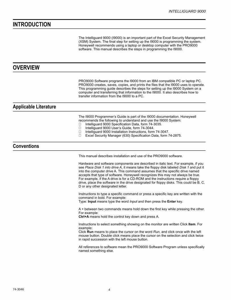
Fig. 2. Blank file ready to be programmed. User can perform any operation from this panel.
4. Click File to display the File pull-down menu again.5. Click Save As to save the program under a new name.
NOTE: File names must have eight or fewer characters.
6. Type filename.7. Click OK to save the information in a new file.

INTELLIGUARD 9000
9 74-3046
OPENING AN EXISTING FILE
If the selected file already exists, use that file by opening it and editing it as needed.
1. In the main menu, click OK.2. Click File to display the File pull-down menu.3. Click Open to display the Open File screen. See Fig. 3.
Fig. 3. Open file screen allows user to open any existing file.
4. Double click the file to be opened. The desired file appears on the screen.

INTELLIGUARD 9000
74-3046 10
SAVING A FILE UNDER A NEW NAME
Fig. 4. Save file as screem.
3. Type a file name into the Name field.4. Click OK to save the file with that name.
NOTE: Pro9000 is a DOS application. Make sure names contain eight or fewercharacters.
1. Click File to display the File pull-down menu.2. Click Save As to display the Save file as screen. See Fig. 4.
INTELLIGUARD 9000
11 74-3046
PROGRAMMING A FILE
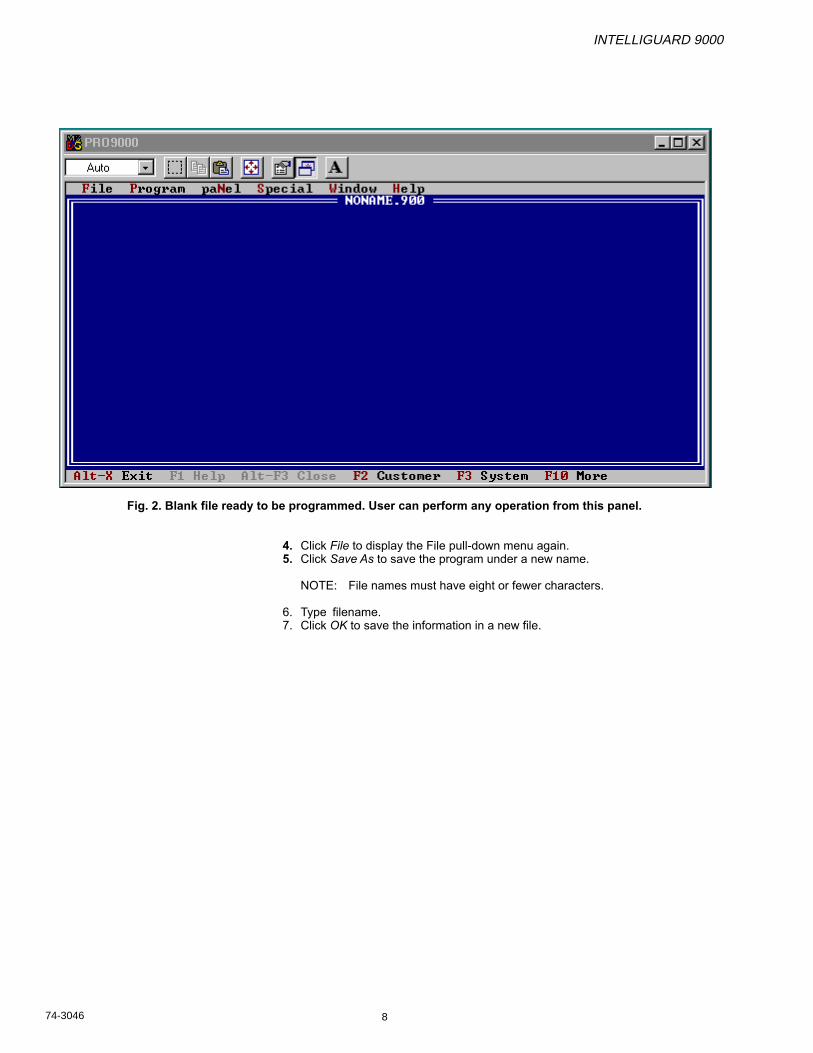
Each file has nine tables. Access each table from the Program pull-down menu.Each table contains information related to one part of the I9000 System. I9000learns each part of the system as part of its startup.
1. Click Program to display the Program pull-down menu. See Fig. 5.
Fig. 5. Open file with Program pull-down menu selected. User can access any of the tables listed except IDs.
NOTES:— Programming must be done Customer, System, and then Polling in sequence.
The remaining tables can be programmed in any sequence.— The IDs table cannot be programmed with PRO9000 Software. Upload it from
an existing system and then download it back to that system.
a. CUSTOMERb. SYSTEMc. POLLING
• MESSAGES• AREAS• RELAYS• INPUTS• OUTPUTS• IDs

INTELLIGUARD 9000
74-3046 12
Defining Customer Information Table
1. In the new screen, press F2 to display the Customer Information table.See Fig. 6.
Fig. 6. Customer Information table. User enters customer information in this table.
2. Click once in the I.D. field.3. Type the desired I.D. number or name.4. Press Tab to move to the Name field.5. Type the customer name in the Name field.6. Press Tab to get to the Address field.7. Type the customer address in the Address field.
NOTE: Press Tab to move to the next line in the Address field.
8. Press Tab to get to the Telephone field.9. Type the customer’s telephone number in the Telephone field.
10. Tab to the Comments field.11. Type any messages in the Comments field.12. Click OK or press Enter to return to the main screen.
NOTE: Pressing Cancel at any time undoes all entries in the active screen.
13. Click File to display the File pull-down menu.14. Click Save to save the Customer file.
NOTE: Honeywell recommends saving the file periodically during and aftercompleting each table.
INTELLIGUARD 9000
13 74-3046
Defining the System Configuration Table
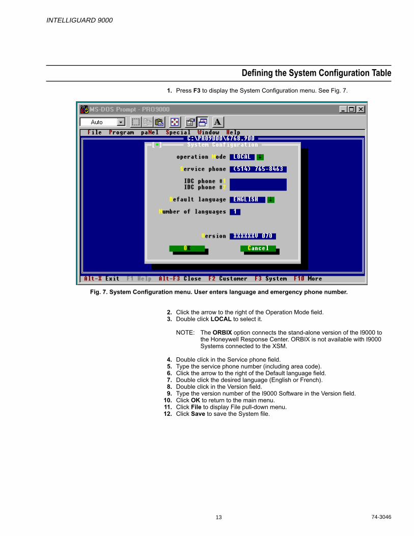
1. Press F3 to display the System Configuration menu. See Fig. 7.
Fig. 7. System Configuration menu. User enters language and emergency phone number.
2. Click the arrow to the right of the Operation Mode field.3. Double click LOCAL to select it.
NOTE: The ORBIX option connects the stand-alone version of the I9000 tothe Honeywell Response Center. ORBIX is not available with I9000Systems connected to the XSM.
4. Double click in the Service phone field.5. Type the service phone number (including area code).6. Click the arrow to the right of the Default language field.7. Double click the desired language (English or French).8. Double click in the Version field.9. Type the version number of the I9000 Software in the Version field.
10. Click OK to return to the main menu.11. Click File to display File pull-down menu.12. Click Save to save the System file.
INTELLIGUARD 9000
74-3046 14
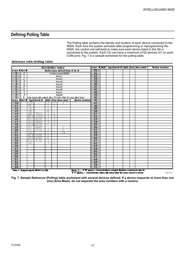
Defining Polling Table
The Polling table contains the identity and location of each device connected to theI9000. Each time the system activates after programming or reprogramming theI9000, the control unit self-tests to make sure each device listed in this file isconnected to the system. Each CU can have a maximum of 62 devices (31 on eachCOM port). Fig. 7 is a sample worksheet for the polling table.
Fig. 7. Sample Reference (Polling) table worksheet with several devices defined. If a device responds to more than onearea (Area Mask), do not separate the area numbers with a comma.
INTELLIGUARD 9000
15 74-3046
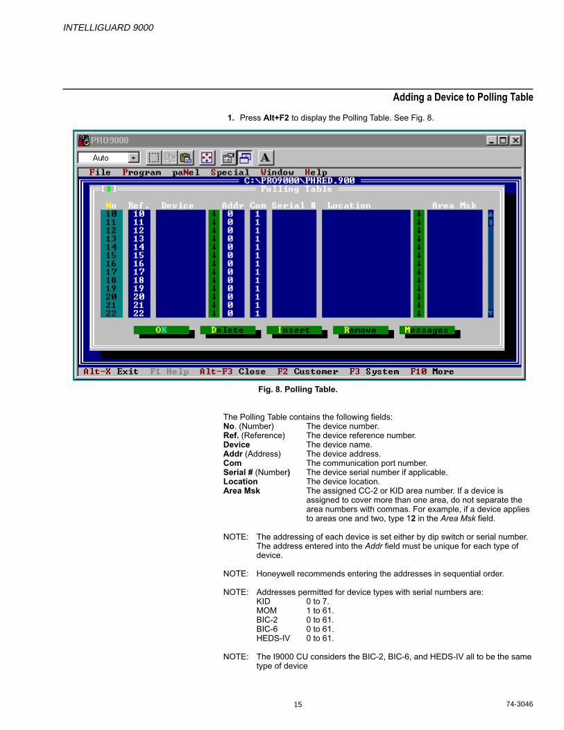
Adding a Device to Polling Table
1. Press Alt+F2 to display the Polling Table. See Fig. 8.
Fig. 8. Polling Table.
The Polling Table contains the following fields:No. (Number) The device number.Ref. (Reference) The device reference number.Device The device name.Addr (Address) The device address.Com The communication port number.Serial # (Number) The device serial number if applicable.Location The device location.Area Msk The assigned CC-2 or KID area number. If a device is
assigned to cover more than one area, do not separate thearea numbers with commas. For example, if a device appliesto areas one and two, type 12 in the Area Msk field.
NOTE: The addressing of each device is set either by dip switch or serial number.The address entered into the Addr field must be unique for each type ofdevice.
NOTE: Honeywell recommends entering the addresses in sequential order.
NOTE: Addresses permitted for device types with serial numbers are:KID 0 to 7.MOM 1 to 61.BIC-2 0 to 61.BIC-6 0 to 61.HEDS-IV 0 to 61.
NOTE: The I9000 CU considers the BIC-2, BIC-6, and HEDS-IV all to be the sametype of device
INTELLIGUARD 9000
74-3046 16
The Polling Table has the following buttons to edit information:OK Accepts any changes made to the Polling Table.Delete Removes a device from a row, but does not remove the row.Insert Creates a new row for additional devices. The number of rows
increases by one.Remove Removes a row and any device in that row. The number or rows
reduces by one.Messages Displays the Messages panel.
2. Click the arrow to the right of the Device field until your choice appears.3. Double click the device name choice in the pull-down menu.4. Press Tab to go to the Addr field.5. Enter the device address.6. Press Tab to go to the Com field.7. Enter the Com number to which the device is connected.8. Press Tab to go to the Serial # field.
NOTE: Locate the serial number on a label attached to the device.
9. Type the serial number into the field if the device has a serial number.10. Click the arrow to the right of the Location field until the desired location choice
appears.11. Double click the location choice in the pop-up menu.12. Press Tab to go to Area Msk field.13. Enter the area numbers where you want to assign the CC-2 or KID.14. Repeat steps 2 through 13 for each device connected to the I9000.15. Click OK to accept the changes.16. Click File to display the File pull-down menu.17. Click Save to save the changes to the Polling Table.
INTELLIGUARD 9000
17 74-3046
Defining System Messages Table
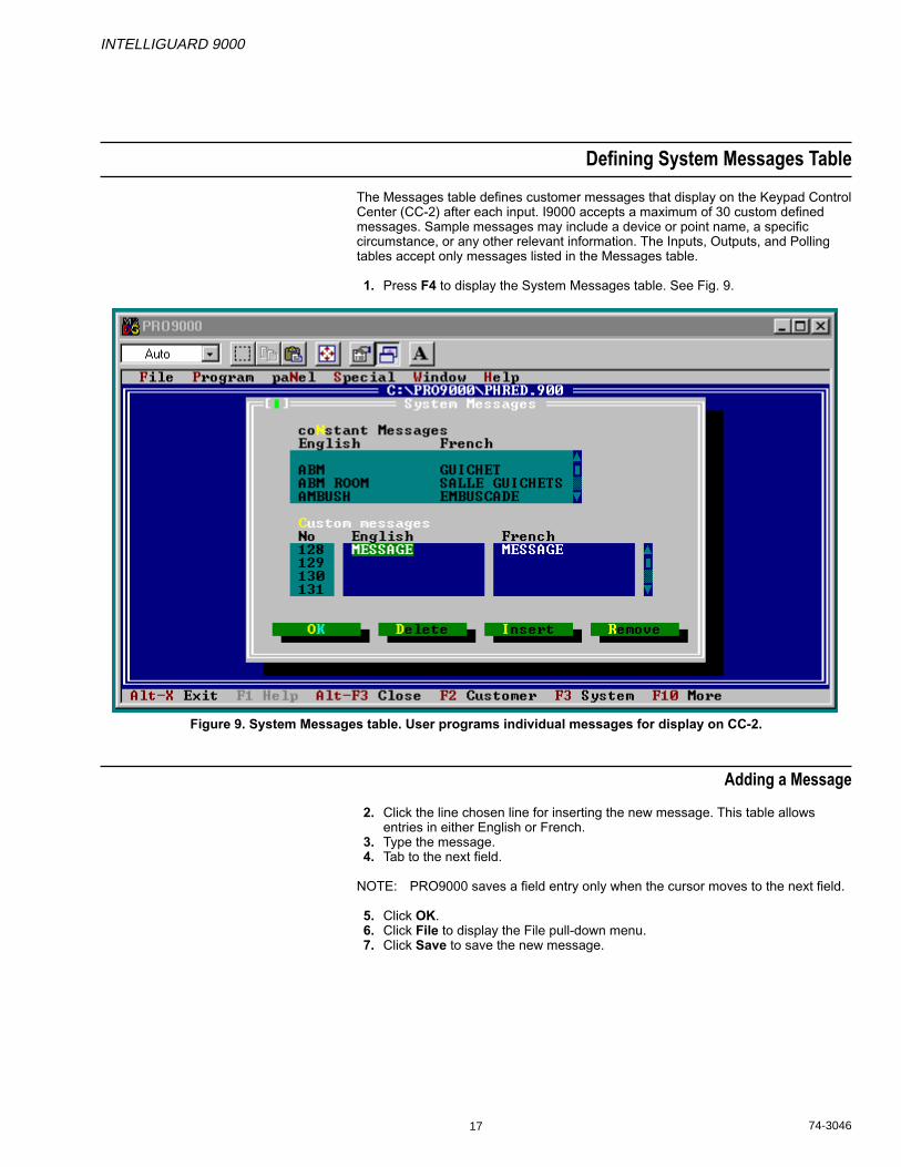
The Messages table defines customer messages that display on the Keypad ControlCenter (CC-2) after each input. I9000 accepts a maximum of 30 custom definedmessages. Sample messages may include a device or point name, a specificcircumstance, or any other relevant information. The Inputs, Outputs, and Pollingtables accept only messages listed in the Messages table.
1. Press F4 to display the System Messages table. See Fig. 9.
Figure 9. System Messages table. User programs individual messages for display on CC-2.
Adding a Message
2. Click the line chosen line for inserting the new message. This table allowsentries in either English or French.
3. Type the message.4. Tab to the next field.
NOTE: PRO9000 saves a field entry only when the cursor moves to the next field.
5. Click OK.6. Click File to display the File pull-down menu.7. Click Save to save the new message.
INTELLIGUARD 9000
74-3046 18
Deleting a Message
NOTE: This procedure deletes the selected message without changing themessage numbers for other messages.
1. Press F4 to display the System Messages table.2. Click on the message to be deleted.3. Click Delete to delete the message.4. Click OK.5. Click File to display the File pull-down table.6. Click Save to save the change.
Removing a Message
NOTE: This procedure deletes the selected message and moves all followingmessages up one line.
1. Press F4 to display the System Messages menu.2. Click on the message to be removed.3. Click Remove.4. Click OK.5. Click File to display the File pull-down menu.6. Click Save to save the change.
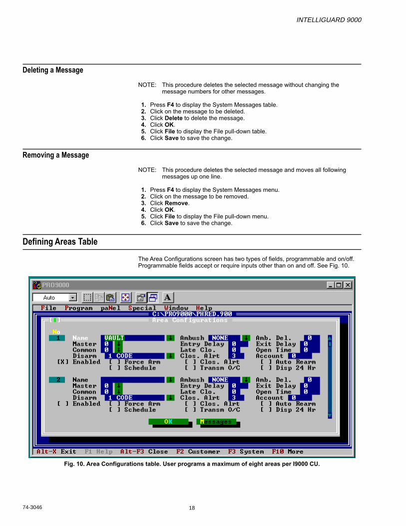
Defining Areas Table
The Area Configurations screen has two types of fields, programmable and on/off.Programmable fields accept or require inputs other than on and off. See Fig. 10.
Fig. 10. Area Configurations table. User programs a maximum of eight areas per I9000 CU.
INTELLIGUARD 9000
19 74-3046
Programmable Fields
Name The name of the area that displays when selecting a procedure.
Ambush An action that must be done in addition to the normal disarmingprocedure. If this additional action is not done, the area sends adistress signal to the I9000 Control Unit. Select from AFTER,BEFORE, and NONE.
Amb. Del. The time limit (in seconds) allowed for performing the Ambushaction.
Master An area that controls one or more other selected area numbers.
Entry Delay The amount of time (in seconds) a person has to disarm the systemafter entering an armed area.
Exit Delay The amount of time (in seconds) a person has to leave an areaafter arming it.
Common The identity number of a specific area that arms and disarmsassociated areas. Areas with a common identity number arm whenthe last area in the group arms. These areas also disarm when thefirst area in the group disarms.
Late Clo. The maximum times allowed for extending the closing time afternormal business hours. This field allows values 1 through 7. Eachtime the closing alert sounds, the closing time can be extended twohours.
Open Time The time limit (2 to 240 minutes) before a disarmed area rearmsautomatically.
Disarm The number of codes or other actions required to disarm an area.Choices are 0 codes, 1 code, 2 codes, IN+1 code, and IN+2 codes.
Clos. Alrt. A message that an area will arm within x time after the messageappears.
Account A three-digit number that identifies an area for the customer servicecenter if an IDC is used. (Not available with XSM system.)
ON/OFF Fields
Press the space bar to toggle each of the following fields on or off.
Enabled Select to activate an area.
Force Arm Allows the operator to arm an area when there are points in thearea in alarm.
Clos Alrt Select to activate warning sounds before an area arms.
Auto Rearm Selects to arm the area either on a schedule or with a remotecommand.
Schedule Select if desired for the I9000 schedule to control area disarming.
Transm O/C Select for an area to send its opening and closing signal to theXSM control center.
INTELLIGUARD 9000
74-3046 20
IMPORTANTDo not use the seal/unseal algorithm on the XSM. The I9000 reactsdifferently from the Security Management Panel (SMP). This may produceunpredictable results on the XSM and I9000. Refer to the XSM Installationmanual, form 74-2875 for more information.
Disp 24 Hr Select to display area-selected abnormal points only whendisarmed. Select to control whether the selected abnormal pointsare displayed at all times on the CC-2.
Detailed Procedure
NOTE: Make sure to tab one field past the last desired entry before clicking OK.
1. Press F7 to display the Area Configurations menu.2. Select a name for Area 1.
a. Click the arrow to the right of the Name field.b. Double click on the area name.c. Press tab to go to the next field.
3. Set Ambush.a. Click the arrow to the right of the Ambush field.b. Double click the selection in the pop-up list.c. Press tab to go to the next field.
4. Set Ambush Delay.a. Click once in the Amb. Del. field.b. Type the desired value in the Amb. Del. field.c. Press tab to go to the next field.
5. Set Master.a. Click the arrow to the right of the Master field.b. Double click the selection in the pop-up list.c. Press tab to go to the next field.
6. Set Entry Delay.a. Click once in the Entry Delay field.b. Type the desired value in the Entry Delay field.c. Press tab to go to the next field.
7. Set Exit Delay.a. Click once in the Exit Delay field.b. Type the desired value in the Exit Delay field.c. Press tab to go to the next field.
8. Set Common.a. Click the arrow to the right of the Common field.b. Double click the selection in the pop-up list.c. Press tab to go to the next field.
9. Late Close.a. Click once in the Late Clo. field.b. Type the desired value in the Late Clo. field.c. Press tab to go to the next field.
10. Set Open Time.a. Click once in the Open Time field.b. Type the desired value in the Open Time field.c. Press tab to go to the next field.
11. Set Disarm.a. Click the arrow to the right of the Disarm field.b. Double click the selection in the pop-up list.c. Press tab to go to the next field.
12. Set Close Alert.a. Click once in the Clos. Alrt field.b. Type the desired value in the Clos. Alrt field.
NOTE: The closing alert can be from 2 to 15 minutes.
c. Press tab to go to the next field.

INTELLIGUARD 9000
21 74-3046
IMPORTANTThe Account Number field is inactive in I9000 systems linked to XSM. TheI9000 address must be set in the System Configuration menu located onthe CC-2.
13. Set Enabled on/off.a. Click the field for the desired setting [X]=on, [N]=off.b. Press tab to go to the next field.
14. Set Force Arm on/off.a. Click the field for the desired setting [X]=on, [N]=off.b. Press tab to go to the next field.
15. Set Clos. Alrt on/off.a. Click the field for the desired setting [X]=on, [N]=off.b. Press tab to go to the next field.
16. Set Auto Rearm on/off.a. Click the field for the desired setting [X]=on, [N]=off.b. Press tab to go to the next field.
17. Set Schedule on/off.a. Click the field for the desired setting [X]=on, [N]=off.b. Press tab to go to the next field.
18. Set Transm O/C on/off.a. Click the field for the desired setting [X]=on, [N]=off.b. Press tab to go to the next field.
19. Set Disp 24 Hr. on/off.a. Click the field for the desired setting [X]=on, [N]=off.b. Press tab to go to the next field.
20. Repeat steps 1 through 19 for each area.21. Click OK to accept the Area Configuration settings.22. Click File to display the File pull-down menu.23. Click Save to save the settings.

INTELLIGUARD 9000
74-3046 22
Defining Relay Functions Table
Fig. 11 Relay Function Table. Each area allows any combination of relay functions.
INTELLIGUARD 9000
23 74-3046
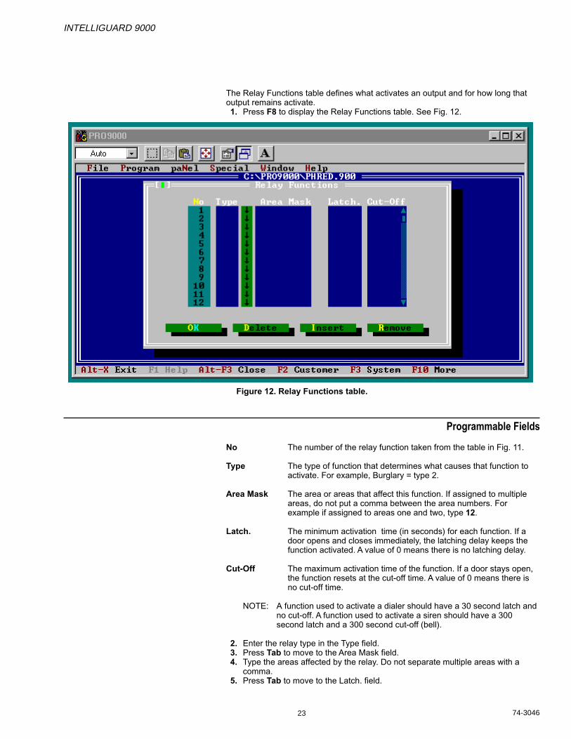
The Relay Functions table defines what activates an output and for how long thatoutput remains activate.1. Press F8 to display the Relay Functions table. See Fig. 12.
Figure 12. Relay Functions table.
Programmable Fields
No The number of the relay function taken from the table in Fig. 11.
Type The type of function that determines what causes that function toactivate. For example, Burglary = type 2.
Area Mask The area or areas that affect this function. If assigned to multipleareas, do not put a comma between the area numbers. Forexample if assigned to areas one and two, type 12.
Latch. The minimum activation time (in seconds) for each function. If adoor opens and closes immediately, the latching delay keeps thefunction activated. A value of 0 means there is no latching delay.
Cut-Off The maximum activation time of the function. If a door stays open,the function resets at the cut-off time. A value of 0 means there isno cut-off time.
NOTE: A function used to activate a dialer should have a 30 second latch andno cut-off. A function used to activate a siren should have a 300second latch and a 300 second cut-off (bell).
2. Enter the relay type in the Type field.3. Press Tab to move to the Area Mask field.4. Type the areas affected by the relay. Do not separate multiple areas with a
comma.5. Press Tab to move to the Latch. field.

INTELLIGUARD 9000
74-3046 24
6. Enter the minimum activation time for that function.7. Press Tab to move to the Cut-Off field.8. Enter the maximum activation time.9. Repeat steps 1 through 8 for each relay.
10. Press OK to accept the changes.11. Click File to display the File pull-down menu.12. Click Save to save the entered values.
Defining the Input Points Table
The Point programming table assigns each input to a specific device as shown inFig. 13.
Fig. 13. Point programming worksheet. Notice each point requires reference and input numbers for devices andmessages.
INTELLIGUARD 9000
25 74-3046
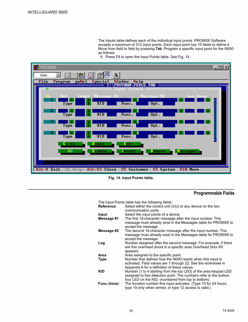
The Inputs table defines each of the individual input points. PRO9000 Softwareaccepts a maximum of 512 input points. Each input point has 10 fields to define it.Move from field to field by pressing Tab. Program a specific input point for the I9000as follows:1. Press F9 to open the Input Points table. See Fig. 14.
Fig. 14. Input Points table.
Programmable Fields
The Input Points table has the following fields:Reference Select either the control unit (CU) or any device on the two
communication ports.Input Select the input points of a device.Message #1 The first 14-character message after the input number. This
message must already exist in the Messages table for PRO9000 toaccept the message.
Message #2 The second 14-character message after the input number. Thismessage must already exist in the Messages table for PRO9000 toaccept the message.
Log Number assigned after the second message. For example, if thereare five overhead doors in a specific area Overhead Door #5appears.
Area Area assigned to the specific point.Type Number that defines how the I9000 reacts when this input is
activated. Field values are 1 through 22. See the worksheet inAppendix A for a definition of these values.
KID Number (1 to 4 starting from the top LED) of the area keypad LEDassigned to this detection point. The numbers refer to the bottomfour LED on the KID, (numbered from top to bottom).
Func.(tions) The function number this input activates. (Type 10 for 24 hours,type 19 only when armed, or type 12 access is valid.)
INTELLIGUARD 9000
74-3046 26
Opt.(ions) Sum of all options selected for this point. For example, if the pointhas bypass and force arm capabilities, add that to the value forlocal only (not to XSM). Bypass = 1, force arm = 2, annunciation forCC-2=8, sound for CC-2=16, local=32. 1+2+8+16+32=59, so 59 isthe required number in the Opt. field.
The Input points table has eight buttons for moving through and editing its fields:Go to Allows the screen display to move to a specific input device
number.Begin Moves the display to the first input device.End Moves the display to the last input device.OK Accepts changes made in the panel.Delete Deletes the device entry but leaves the fields for other entries.Insert Inserts one line, moving succeeding points back one.Remove Removes one point. All points move forward one.Messages Displays the Messages panel.
2. Program the first input point by tabbing to each field and adding the requiredinformation for that device.
3. Repeat step 2 for each additional input you want to program.4. Click OK to accept the entries.5. Click File to display the File pull-down menu.6. Click Save to save the entries.
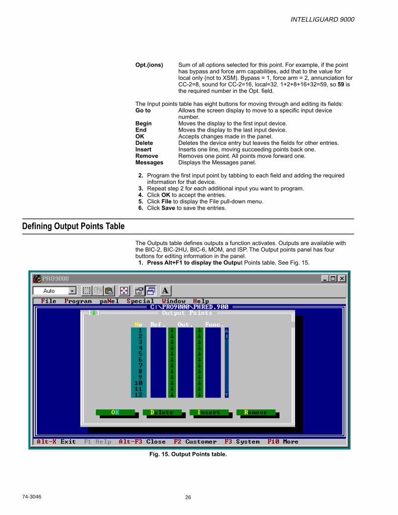
Defining Output Points Table
The Outputs table defines outputs a function activates. Outputs are available withthe BIC-2, BIC-2HU, BIC-6, MOM, and ISP. The Output points panel has fourbuttons for editing information in the panel.1. Press Alt+F1 to display the Output Points table. See Fig. 15.
Fig. 15. Output Points table.

INTELLIGUARD 9000
27 74-3046
Programmable Fields
The Output Points table defines location, address and function for each output point.An output can activate a bell, siren, light or other such device. The following fieldsdefine all output points:
No. Output point number of the I9000.Ref. Reference number of the device output location.Out. Output number assigned to the device.Func. Relay function number that activates this output.
The following buttons affect the Output Points table.Insert Inserts one line, moving succeeding outputs back one.Delete Erases the entry but leaves the line available for future use.Remove Removes the line, moving outputs forward one.OK Accepts any changes and exits the table.
2. Type in the output device reference number.3. Press Tab to move to the next field.4. Type in the applicable output number of the device.5. Tab to move to the next field.6. Type in the applicable relay function number.7. Tab to move to the next output number.8. Repeat steps 2 through 7 for each output point.9. Tab to the next field.
10. Click OK to accept the field entries.11. Click File to display the File pull-down menu.12. Click Save to save the changes.

INTELLIGUARD 9000
74-3046 28
COPYING FILES FROM A PC TO THE I9000
Program the I9000 by editing files in a PC and then copying them to the I9000Control Unit. Transfer information from the PC to the I9000 Control Unit through ashielded RS-232 cable.1. Connect the cable to the PC and the I9000.2. Click Special to display the Special pull-down menu. See Fig. 16.
NOTE: Write XSM File, Forget changes, and Check program are not available atthis time.
Fig.16. Main menu with Special pull-down menu selected.
INTELLIGUARD 9000
29 74-3046
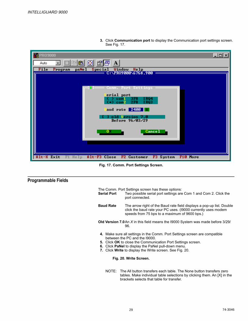
3. Click Communication port to display the Communication port settings screen.See Fig. 17.
Fig. 17. Comm. Port Settings Screen.
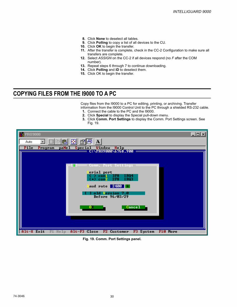
Programmable Fields
The Comm. Port Settings screen has these options:Serial Port Two possible serial port settings are Com 1 and Com 2. Click the
port connected.
Baud Rate The arrow right of the Baud rate field displays a pop-up list. Doubleclick the baud rate your PC uses. (I9000 currently uses modemspeeds from 75 bps to a maximum of 9600 bps.)
Old Version 7.0An X in this field means the I9000 System was made before 3/29/96.
4. Make sure all settings in the Comm. Port Settings screen are compatiblebetween the PC and the I9000.
5. Click OK to close the Communication Port Settings screen.6. Click PaNel to display the PaNel pull-down menu.7. Click Write to display the Write screen. See Fig. 20.
Fig. 20. Write Screen.
NOTE: The All button transfers each table. The None button transfers zerotables. Make individual table selections by clicking them. An [X] in thebrackets selects that table for transfer.
INTELLIGUARD 9000
74-3046 30
COPYING FILES FROM THE I9000 TO A PC
Copy files from the I9000 to a PC for editing, printing, or archiving. Transferinformation from the I9000 Control Unit to the PC through a shielded RS-232 cable.1. Connect the cable to the PC and the I9000.2. Click Special to display the Special pull-down menu.3. Click Comm. Port Settings to display the Comm. Port Settings screen. See
Fig. 19.
Fig. 19. Comm. Port Settings panel.
8. Click None to deselect all tables.9. Click Polling to copy a list of all devices to the CU.
10. Click OK to begin the transfer.11. After the transfer is complete, check in the CC-2 Configuration to make sure all
transfers are complete.12. Select ASSIGN on the CC-2 if all devices respond (no F after the COM
number).13. Repeat steps 6 through 7 to continue downloading.14. Click Polling and iD to deselect them.15. Click OK to begin the transfer.
INTELLIGUARD 9000
31 74-3046
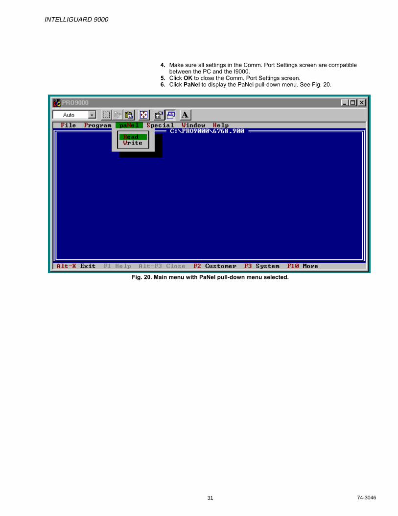
4. Make sure all settings in the Comm. Port Settings screen are compatiblebetween the PC and the I9000.
5. Click OK to close the Comm. Port Settings screen.6. Click PaNel to display the PaNel pull-down menu. See Fig. 20.
Fig. 20. Main menu with PaNel pull-down menu selected.

INTELLIGUARD 9000
74-3046 32
7. Click Read to display the Read panel. See Fig. 21.
Fig. 21. Read Panel.
NOTE: The All button transfers every table. The None button transfers zerotables. Make individual table selections by clicking them. An [X] in thebrackets selects that table for transfer.
8. Make sure the tables to be transferred are selected.9. Click OK to begin the transfer.

INTELLIGUARD 9000
33 74-3046
PRINTER SETUP
The Printer Setup panel tells the I9000 how the printer interface (PIF) connects tothe system computer.1. Click Special to display the Special pull-down menu.2. Click Printer to display the Printer Settings screen. See Fig. 22.
Fig. 22. Printer Settings panel.
Programmable Fields
The Printer Settings panel has:LPT1 Click this button to print to LPT1.
LPT2 Click this button to print to LPT2.
File Click this button to print to a specific file.
Add Form Feed at end Select [X] to add a form feed to the end of a print job asnecessary for some printers.
3. Click OK to accept the entries.

INTELLIGUARD 9000
74-3046 34
PRINTING LOG FILES
Print program files for a paper record of the program:1. Click File to display the File pull-down menu.2. Click Open to display the list of files.3. Double click the file to be opened.4. Click File to display the File pull-down menu.5. Click Print to display the Print Reports panel. See Fig. 23.
Fig. 23. Print Reports panel.
6. Click OK to print all tables.
INTELLIGUARD 9000
35 74-3046
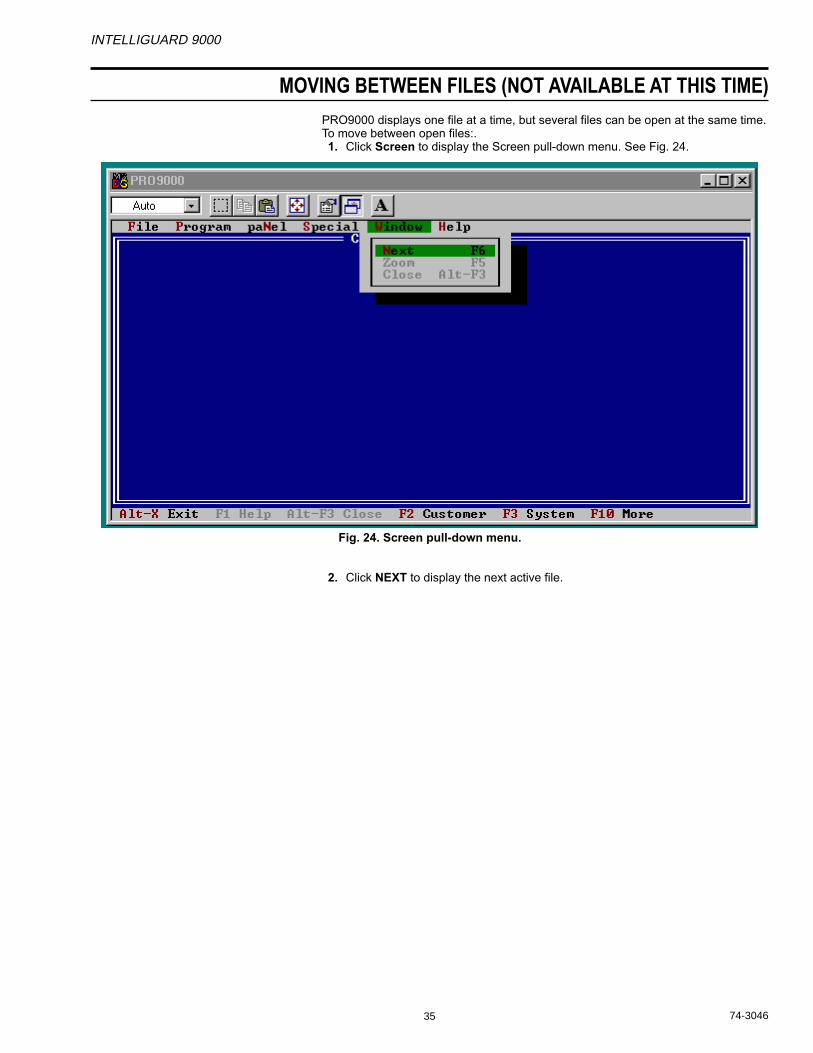
MOVING BETWEEN FILES (NOT AVAILABLE AT THIS TIME)
PRO9000 displays one file at a time, but several files can be open at the same time.To move between open files:.1. Click Screen to display the Screen pull-down menu. See Fig. 24.
Fig. 24. Screen pull-down menu.
2. Click NEXT to display the next active file.
INTELLIGUARD 9000
74-3046 36
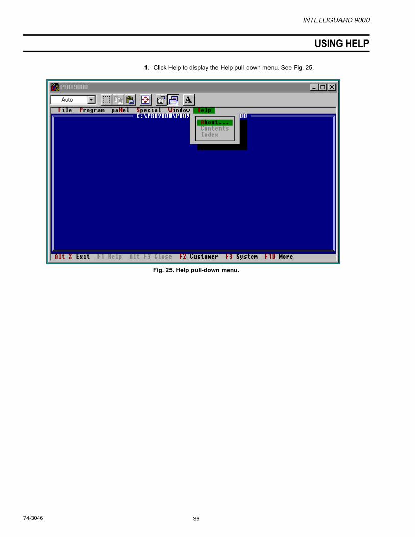
USING HELP
1. Click Help to display the Help pull-down menu. See Fig. 25.
Fig. 25. Help pull-down menu.

INTELLIGUARD 9000
37 74-3046
APPENDIX A WORKSHEETS

Honeywell
INTELLIGUARD 9000
Programming Sheets
Revision 2.2 (99-02-17) XSM E-1011-626
XSM

Inte
llig
uar
d 9
000 m
enu s
truct
ure
(V
/ X
SM
) 9
9/02/05
**
INT
EL
LIG
UA
RD
900
0 **
DA
TE
AN
D T
IME
Pre
ssin
g o
n a
ny
dig
it (
0 to
9)
will
dis
pla
y th
e "A
RM
ST
AT
US
" d
irec
tly
oror
?
T
ES
T
DIS
AR
M
AR
M
MO
DE
O
PT
ION
ME
NU
M
EN
U
ME
NU
M
EN
U
ME
NU
Ver
sio
n #
, ID
A
RE
A ?
__
AR
EA
?__
ID
ID
syst
. typ
e C
OD
E
CO
DE
C
OD
E
and
dat
e
Ser
vice
H
old
-U
p
ID
ID
Sta
tus
1- A
rm (
1 to
8)
tel.
no
. A
rea
1-8
CO
DE
C
OD
E
2- A
larm
(1
to 8
)
Hel
p
3- A
rea
(1 t
o 8
)
Byp
ass
a p
oin
t
men
u in
C
him
e 4-
Po
int
stat
us
(1 t
o 5
12)
even
t lo
g
Are
a 1-
8 R
eset
det
ecto
r
Un
byp
ass
a p
oin
t
Wh
en 3
(
Sm
oke
an
d h
old
-up
)
do
ts (
...)
Wal
k te
st
ID M
anag
emen
t
follo
w's
A
rea
1-8
Eve
nt
log
(A
ll ev
ents
)
the
text
1- A
DD
def
init
ion
*R
eset
log
/ O
RB
IX b
uff
er
2- D
elet
e
Will
gav
e n
ame
of
and
res
ets
"M"
in a
ssig
n t
able
(ID
+ C
od
e)
area
(s)
if '
'?''
is
pre
ssed
3-
Mo
dif
y
ever
y ti
me
the
*C
on
fig
ura
tio
n
(A
rea,
Au
th. l
evel
, lan
g.)
dis
pla
y as
ks f
or
PA
GE
2
Ch
ang
e co
de
an A
RE
A #
_?
* T
EC
HN
ICIA
N O
NL
Y
Th
an u
se t
he
do
wn
Sch
edu
les
(Arm
/dis
arm
)
arro
w t
o s
ee o
ther
A
rm p
arti
al (
Per
imet
er)
area
(s)
(
) (A
rea
1 to
8)
Tim
e ch
ang
e (D
LS
/ST
D)
Day
,mo
nth
Lat
e cl
osi
ng
(ex
ten
tio
n o
f cl
osi
ng
)
Rep
rin
t lo
g (
All
even
ts)
No
te:
Yo
u c
an m
ove
fro
m O
PT
ION
men
u t
o
MO
DE
or
TE
ST
men
u d
irec
tly
wit
ho
ut
hav
ing
to
exi
t to
MA
IN m
enu
eve
ry t
ime

(Fro
m m
od
e o
n p
age
1)
5- C
ON
FIG
UR
AT
ION
1Le
arn
CC
-2 (
Lear
ned
aut.
at p
ower
-up)
Dev
ices
with
P
U
Typ
e ad
dres
s P
IF (
Prin
ter)
2A
ssig
n (
Pol
ling
tabl
e)
Adr
ess
IPS
/RIP
S a
nd IS
P
Com
m.
Op
tio
ns
Ser
ial #
B
ypas
s (1
)
Ref
. #
For
ce a
rm (
2)
Dev
ices
with
B
IC (
6 an
d 2
inpu
ts)
Ref
#
Cle
ar to
arm
(4)
se
rial #
K
ID
Inp.
#
Day
sta
tus
(8)
RIL
(S
ame
as a
BIC
-2)
Are
a#
Sou
nd (
16)
HE
DS
-IV
Sam
e as
a B
IC)
Mes
s.-
1 Lo
cal (
32)
MO
M (
Out
. mod
ule)
3P
oint
pro
gram
min
g M
ess.
- 2
2 P
oint
dep
ende
nt (
64)
see
Poi
nt d
escr
iptio
n pa
ge 4
P
oint
type
A
uto.
cle
ar b
ypas
s (1
28)
Op
tio
ns
Lo
g. #
Kid
Led
A
ctiv
e ye
s D
efa
ult
are
a 1
4R
eset
pol
ling
Link
func
.
no
De
fau
lt a
rea
2 t
o 8
Nam
e of
are
a 1
to 6
0 in
tabl
e 3
or 1
28 to
157
in ta
ble
4
5S
yste
m
Pro
toco
l : 0
=S
MP
, 1=
Rem
ote
prog
ram
min
g (P
CP
T
rans
mis
sion
of o
pen/
clos
e (Y
es
or
No)
Adr
ess
(0
to 1
27)
(D
= 1
27)
XS
M-1
S
ched
ules
1
per
day
/per
are
a (o
r to
turn
the
rela
y on
/off)
func
tion
Typ
e #1
7
Bau
d : 0
=75
, 1=
150
, 2=
300
bau
d E
ntry
del
ay
(for
ULC
max
60 s
ec.
)
3=60
0, 4
= 12
00, 5
= 24
00, 6
= 48
00, 7
= 9
600
Exi
t del
ay
(for
ULC
max
120 s
ec.
)
Hon
ewel
l tel
no.
for
serv
ice
For
ce a
rm
(Yes
or
no)
Lang
uage
(0=
fran
çais
, 1=
Eng
lish)
P
in P
oint
(
Yes
or
No )
Dis
arm
mod
e (M
ode
1 to
5)
Am
bush
type
(1
=B
efor
e, 2
= a
fter,
0=
no)
A
mbu
sh d
elay
(I
f am
bush
bef
ore
or a
fter)
6A
rea
par
amet
ers
(A
rea
1 to
8)
Late
clo
sing
(M
axim
um o
f 7 r
eque
sts)
Late
clo
sing
ale
rt
( Y
es
or
No
)
7R
elay
(0
to 6
4)
Typ
e (1
to 2
1)
Sla
ve to
are
a (A
ny a
rea)
func
tions
A
rea
(1 to
8)
Com
mon
are
a (O
ne
are
a o
nly
)
Del
ay (
0 to
409
5 se
c) M
in.
Clo
sing
ale
rt
(
15
min
utes
max
.)
Cut
off
time
(0 to
409
5 se
c.)
Max
. O
pen
time
( 4
hour
s )
R
earm
M/S
(a
t th
e e
nd
of
the
sch
ed
ule
)
8O
utpu
t poi
nts
(Poi
nt, r
ef.#
,out
.#, f
unc.
#)
1 to
64
Dsp
Sts
24
hrs
(Dis
play
sta
tus
on U
IF o
r C
C-2
) (Y
es
or
No
)
9S
et c
lock
(H
ours
, min
utes
, day
: SU
ND
AY
=1)
(Dat
e, m
onth
, yea
r)
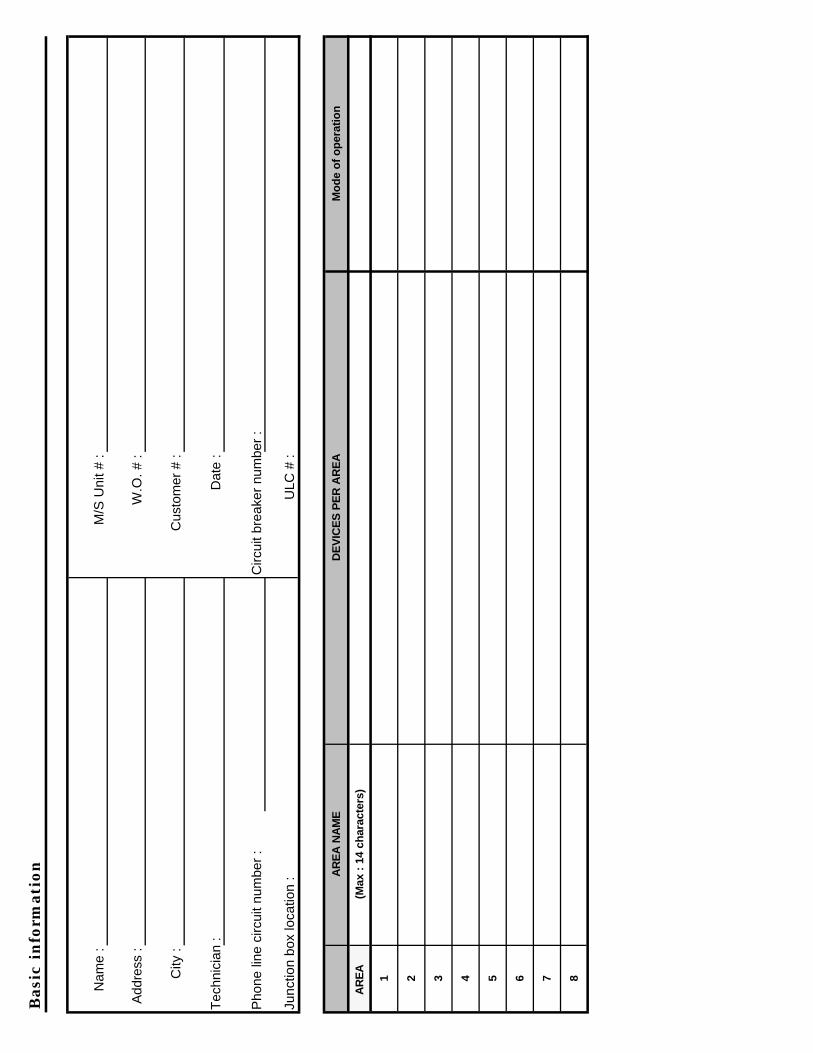
Bas
ic i
nfo
rmat
ion
Nam
e :
M/S
Uni
t # :
Add
ress
: W
.O. #
:
City
: C
usto
mer
# :
Tec
hnic
ian
: D
ate
:
Pho
ne li
ne c
ircui
t num
ber
: C
ircui
t bre
aker
num
ber
:
Junc
tion
box
loca
tion
: U
LC #
:
AR
EA
NA
ME
D
EV
ICE
S P
ER
AR
EA
M
od
e o
f o
per
atio
n
AR
EA
(M
ax :
14
char
acte
rs)
1 2 3 4 5 6 7 8

Poin
t ty
pe
det
erm
ines
how
th
e poin
t re
acts
(T
able
2) D
efin
itio
n
No
TY
PE
D
ESC
RIP
TIO
N
0N
O A
CT
ION
T
he in
put i
s ig
nore
d by
the
9000
.
1 E
/E D
EL
AY
A
ssig
ned
to d
oors
that
are
ope
ned
befo
re d
isar
min
g .In
depe
nden
t tim
ers
for
entr
y an
d ex
it on
eac
h ar
ea.
2 A
RM
AR
EA
F
or in
terf
acin
g to
a c
ontr
ol a
cces
s sy
stem
. Any
act
ivat
ion
will
onl
y ar
m th
e ar
ea o
nce.
3 IN
TE
RIO
R
For
mot
ion
dete
ctor
s. W
ill c
ause
an
alar
m if
act
ivat
ed b
efor
e an
E/E
poi
nt.
4 IN
ST
AN
T
The
se p
oint
will
cau
se a
n im
med
iate
ala
rm if
the
corr
espo
ndin
g ar
ea is
arm
ed.
5 P
ER
MA
NE
NT
W
ill c
ause
a b
urgl
ar a
larm
reg
ardl
ess
of th
e ar
ea a
rmed
sta
te.
6 F
IRE
F
or s
mok
e an
d he
at d
etec
tors
and
wat
erflo
w a
larm
poi
nts,
will
act
ivat
e th
e fir
e fu
nctio
n.
7 H
OL
D-U
P
For
hol
d-up
act
uato
r, a
ctiv
e 24
hou
rs. T
he p
oint
can
be
verif
ied
whi
le in
the
hold
-up
test
mod
e.
8 H
OL
D-U
P D
AY
F
or h
old-
up a
ctua
tor
that
sha
ll re
act o
nly
whe
n th
e co
rres
pond
ing
area
is d
isar
med
.
9 A
RM
/DIS
AR
M
Eac
h m
omen
tary
act
ivat
ion
will
togg
le th
e ar
ea s
tate
bet
wee
n ar
m a
nd d
isar
m.
MO
ME
NT
AR
Y
10
AR
M /
DIS
AR
M
To
arm
and
dis
arm
with
a k
ey s
witc
h.
MA
INT
AIN
ED
11
AM
BU
SH
RE
SE
T
To
stop
the
ambu
sh ti
mer
. An
area
key
pad
can
be u
sed
as a
n am
bush
res
et a
nd p
rovi
de a
n au
dit t
rail
of th
e se
quen
ce
12
DIS
AR
M A
RE
A
For
inte
rfac
ing
to a
con
trol
acc
ess
syst
em. A
ny a
ctiv
atio
n w
ill o
nly
disa
rm th
e ar
ea o
nce.
13
INS
TA
NT
RE
SE
T R
EL
AY
F
or c
ontr
ol a
cces
s, to
rel
ock
the
door
. Whe
n th
e ar
ea is
arm
ed, w
ill a
ct a
s an
inst
ant p
oint
.
14
INS
TA
NT
SE
T R
EL
AY
F
or c
ontr
ol a
cces
s, to
rel
ease
a d
oor
(RE
X).
Whe
n th
e ar
ea is
arm
ed, w
ill a
ct a
s an
inst
ant p
oint
.
15
SU
PE
RV
ISIO
N
For
non
e-bu
rgla
ry p
oint
s, w
ill a
ctiv
ate
the
supe
rvis
ory
func
tion.
16
AM
BU
SH
/DU
RE
SS
W
ill a
ctiv
ate
a si
lent
ala
rm a
nd th
e am
bush
func
tion.
17
AC
FA
IL
Whe
n a
spec
ific
actio
n is
req
uire
d w
hen
AC
fails
.
18
ME
SS
AG
E
For
dis
play
and
eve
nt lo
ggin
g on
ly.
19E
NA
BL
E D
ISA
RM
For
app
licat
ions
that
req
uire
hig
h se
curit
y. A
ctiv
atio
n of
this
poi
nt w
ill e
nabl
e ke
ypad
dis
arm
ing
for
15 m
inut
es.
20
TA
MP
ER
INP
UT
U
sed
for
DE
VIC
ES
and
PR
OT
EC
TIO
N E
QU
IPM
EN
T'S
tam
per
switc
hes.
( w
hen
area
is d
isar
med
= T
roub
le, a
rmed
= A
larm
)
21
AU
TO-A
RM
AR
EA
W
hen
the
area
is a
rmed
this
poi
nt c
reat
es a
n in
stan
t ala
rm. W
hen
disa
rmed
and
this
poi
nt r
etur
ns to
nor
mal
the
area
arm
s.
22
DO
OR
AC
CE
SS
Thi
s po
int c
reat
es a
n in
stan
t Ala
rm w
hen
area
is a
rmed
, tro
uble
whe
n di
sarm
ed. I
f acc
ess
type
func
tion
num
ber
is e
nter
ed in
Lin
k,
the
burg
lary
trou
ble
func
tion
will
com
e on
whe
n th
e cu
t off
time
of th
e ac
cess
func
tion
expi
res.
Op
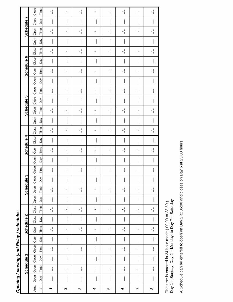
enin
g /
clo
sin
g (
and
Rel
ay )
sch
edu
les
Are
a O
pen
Ope
nC
lose
Clo
seO
pen
Ope
nC
lose
Clo
seO
pen
Ope
nC
lose
Clo
seO
pen
Ope
nC
lose
Clo
seO
pen
Ope
nC
lose
Clo
seO
pen
Ope
nC
lose
Clo
seO
pen
Ope
nC
lose
Clo
se
# D
ay
Tim
e D
ay
Tim
e D
ay
Tim
e D
ay
Tim
e D
ay
Tim
e D
ay
Tim
e D
ay
Tim
e D
ay
Tim
e D
ay
Tim
e D
ay
Tim
e D
ay
Tim
e D
ay
Tim
e D
ay
Tim
e D
ay
Tim
e
1 __
_:
_ __
_:
_ __
_:
_ __
_:
_ __
_:
_ __
_:
_ __
_:
_ __
_:
_ __
_:
_ __
_:
_ __
_:
_ __
_:
_ __
_:
_ __
_:
_
2 __
_:
_ __
_:
_ __
_:
_ __
_:
_ __
_:
_ __
_:
_ __
_:
_ __
_:
_ __
_:
_ __
_:
_ __
_:
_ __
_:
_ __
_:
_ __
_:
_
3 __
_:
_ __
_:
_ __
_:
_ __
_:
_ __
_:
_ __
_:
_ __
_:
_ __
_:
_ __
_:
_ __
_:
_ __
_:
_ __
_:
_ __
_:
_ __
_:
_
4 __
_:
_ __
_:
_ __
_:
_ __
_:
_ __
_:
_ __
_:
_ __
_:
_ __
_:
_ __
_:
_ __
_:
_ __
_:
_ __
_:
_ __
_:
_ __
_:
_
5 __
_:
_ __
_:
_ __
_:
_ __
_:
_ __
_:
_ __
_:
_ __
_:
_ __
_:
_ __
_:
_ __
_:
_ __
_:
_ __
_:
_ __
_:
_ __
_:
_
6 __
_:
_ __
_:
_ __
_:
_ __
_:
_ __
_:
_ __
_:
_ __
_:
_ __
_:
_ __
_:
_ __
_:
_ __
_:
_ __
_:
_ __
_:
_ __
_:
_
7 __
_:
_ __
_:
_ __
_:
_ __
_:
_ __
_:
_ __
_:
_ __
_:
_ __
_:
_ __
_:
_ __
_:
_ __
_:
_ __
_:
_ __
_:
_ __
_:
_
8 __
_:
_ __
_:
_ __
_:
_ __
_:
_ __
_:
_ __
_:
_ __
_:
_ __
_:
_ __
_:
_ __
_:
_ __
_:
_ __
_:
_ __
_:
_ __
_:
_
The
tim
e is
ent
ered
in 2
4 ho
ur m
ode
( 00
:00
to 2
3:59
)D
ay 1
= S
unda
y, D
ay 2
= M
onda
y, to
Day
7 =
Sat
urda
y
A S
ched
ule
can
be e
nter
ed to
ope
n on
Day
2 a
t 06:
00 a
nd c
lose
s on
Day
6 a
t 23:
00 h
ours
Sch
edu
le 5
S
ched
ule
6
Sch
edu
le 7
Sch
edu
le 1
S
ched
ule
2
Sch
edu
le 3
S
ched
ule
4

Syst
em p
aram
eter
s
Sh
aded
are
as s
ho
w d
efau
lt v
alu
es
1 -
PR
OT
OC
OL
0
SM
P (
XS
M v
ersi
on o
nly)
T
o b
e ab
le t
o c
om
mu
nic
ata
wit
h a
PC
1 P
C p
rog
ram
min
g
Par
amet
ers
1 an
d 3
mu
st b
e se
t p
rop
erly
2 -
AD
DR
ES
S
0 1
0 1
2 3
4 5
6 7
8 9
0 1
2 3
4 5
6 7
8 9
3 -
BA
UD
0
1 2
3 4
5 6
7 B
aud
rate
for
PC
pro
gram
min
g sh
ould
be
set
75
150
300
600
1200
24
00
4800
96
00
at th
e sa
me
spee
d th
at y
our
PC
(24
00 is
sug
gest
ed)
4 -
PH
ON
E
Hon
eyw
ell s
ervi
ce c
ente
r te
leph
one
num
ber
Use
de
UP
and
DO
WN
arr
ow to
inse
rt a
das
h (-
) be
twee
n nu
mbe
rs.
5 -
LA
NG
UA
GE
0
FR
EN
CH
P
rinte
r an
d ID
lang
uage
1 E
NG
LIS
H
No
tes:
-
Th
e 4
op
tion
al p
rin
ters
will
pri
nt
in e
ithe
r F
RE
NC
H o
r E
NG
LIS
H
-T
he
ID
lan
gu
ag
e s
till c
an
be
ch
an
ge
d in
ID
MA
NE
GE
ME
NT
un
de
r "O
PT
ION
"

Poin
t opti
ons
Spec
ifies
the
rela
y fu
nctio
n to
be
cont
rolle
d by
the
inpu
t poi
nt
Det
erm
ines
whi
ch L
ED o
n th
e KI
D w
ill di
spla
y th
e po
int s
tatu
s.
Auto
mat
ical
ly re
mov
es th
e by
pass
15
seco
nds
afte
r the
poi
nt re
stor
es
PO
INT
OP
TIO
N
Byp
. F
. Arm
C
L. A
rm
Day
an
. S
ou
nd
L
oca
l P
t. D
ep.
Au
. Cle
ar
Op
tio
n
Kid
L
ink
1 2
4 8
16
32
64
Byp
.(12
8)
(To
tal)
L
ed
Fu
nc
Bypa
ss
Det
erm
ines
if th
e po
int
can
be m
anua
lly b
ypas
sed
Forc
e Ar
m is
onl
y va
lid if
cle
ar to
arm
is s
et
Det
erm
ines
if a
bnor
mal
poi
nt c
an b
e
auto
mat
ical
ly b
ypas
sed
on a
rmin
g
Cle
ar to
Arm
, if o
ptio
n is
add
ed th
e ar
ea w
ill no
t arm
if th
e po
int i
s ab
norm
al
Day
ann
unci
atio
n, d
eter
min
es if
sta
tus
of a
bnor
mal
poi
nt is
disp
laye
d au
tom
atic
ally
on
the
CC
-2
Soun
d, o
nly
valid
if d
ay a
nnun
ciat
ion
optio
n is
set
Det
erm
ines
if a
n au
dibl
e w
ill be
hea
rd w
hen
the
inpu
t goe
s in
ala
rm
Loca
l det
erm
ines
if s
tatu
s ch
ange
s of
this
poi
nt w
ill be
tran
smitt
ed to
the
XSM
FOR
PO
INT
TYPE
21
ON
LY.
If th
is o
ptio
n is
not
add
ed th
e ar
ea re
arm
tim
er is
sto
pped
whe
n th
e po
int g
oes
abno
rmal
If th
is o
ptio
n is
add
ed th
e ar
ea re
arm
tim
er w
ill co
ntin
ue.
OPT
ION
TO
TAL
(add
all
optio
n nu
mbe
rs [b
inar
y se
quen
ce] )
F. A
RM
D
AY
AN
. S
OU
ND
LO
CA
LO
PT
ION
SE
E E
XA
MP
LE
2
8 16
32
58
EX
AM
PL
E

Are
a par
amet
ers
PA
RA
ME
TE
R D
EF
INIT
ION
P
AR
AM
ET
ER
OP
TIO
NS
D
efau
lt
AR
EA
S
sett
ing
1
2 3
4 5
6 7
8
AC
TIV
E
YE
S O
R N
O (
Unact
ive=
NO
)-
A1=
Yes
AR
EA
NA
ME
(2)
# F
RO
M T
AB
LE 3
OR
4
40
T
ext
FR
OM
TA
BLE
3 O
R 4
N
ot
use
d
TR
AN
SM
ISS
ION
O/C
Y
ES
OR
NO
N
o
SC
HE
DU
LE
A/D
AN
D R
EL
AY
1
SC
HE
DU
LE P
ER
AR
EA
-
-
EN
TR
Y D
EL
AY
0
TO
180
SE
C (
ULC
=60
SE
C.)
0
EX
IT D
EL
AY
0
TO
180
SE
C (
ULC
=12
0 S
EC
.)
0
FO
RC
E A
RM
Y
ES
OR
NO
N
o
Pin
Po
int
YE
S O
R N
O
No
DIS
AR
M M
OD
ES
(1)
0=
no c
ode,
1=
1 c
ode,
2=
2 c
odes
1
3= 1
code
+in
p(P
IM),
4=
2cod
es+
inp(
PIM
)
AM
BU
SH
TY
PE
0=
N0
1=
BE
FO
RE
2
= A
FT
ER
0
AM
BU
SH
DE
LA
Y
BE
FO
RE
= 0
TO
45
MIN
UT
ES
0
AF
TE
R=
0 T
O 1
0 M
INU
TE
S
0
LA
TE
CL
OS
ING
M
AX
IMU
M O
F 7
RE
QU
ES
TS
0
LA
TE
CL
OS
ING
AL
ER
T
YE
S O
R N
O
No
MA
ST
ER
AR
EA
(S
lave
) LI
NK
TO
AR
EA
1 T
O 8
0
CO
MM
ON
AR
EA
A
RE
A #
1 T
O 8
0
CL
OS
ING
AL
ER
T (
Bef
. rea
rm)
2 T
O 1
5 M
INU
TE
S
0
OP
EN
TIM
E (
Rea
rm t
imer
) 0
TO
240
MIN
UT
ES
0
RE
AR
M M
/S (
Au
to r
earm
as
per
.....
...
sch
edul
e
0
= N
O
1=
YE
S
0
DIS
PL
AY
24
HR
S(U
IF &
CC
-2)
Yes
or
No
No
No
te (
1) :
If
the
NO
CO
DE
(0)
op
tio
n is
sel
ecte
d, t
he
area
(s)
can
be
dis
arm
ed O
NL
Y w
ith
a K
ID o
r K
EY
(P
oin
t ty
pe
9,10
,12)
.

Rel
ay t
ypes
(fu
nct
ion
) def
init
ion
A F
UN
CT
ION
CO
UL
D B
E A
SS
IGN
ED
TO
AN
I/O
PID
, A
BIC
-2(i
np
.-1)
, a B
IC-6
VE
RS
ION
2(i
np
. 1 t
o 6
,if p
rog
. as
ou
tpu
t), A
MO
M(o
utp
ut
1 to
8)
AN
D T
O A
N IS
P/R
IPS
(TS
2-3)
, OU
TP
UT
7.
No
T
YP
E
DE
SC
RIP
TIO
N
1 H
old
-up
T
his
func
tion,
will
act
ivat
e w
hen
a H
U a
ctua
tor(
type
7 or
8 )
is d
epre
ssed
in o
ne o
f its
ass
igne
d ar
eas.
The
rel
ay w
ill
rese
t whe
n th
e sw
itch
is b
ack
to n
orm
al (
Afte
r re
set d
etec
tor
com
man
d fr
om C
C-2
, UIF
or
KID
)
2 B
urg
lary
A
ctiv
ates
whe
n a
burg
.al.
is tr
igge
red.
It w
ill r
eset
afte
r th
e al
arm
is r
esto
red,
del
ay/c
utof
f tim
er h
as e
xpire
d or
val
id c
ode
is e
nter
ed o
n ke
ypad
3 F
ire
Any
poi
nt th
at is
pro
gram
med
type
3 F
IRE
will
act
ivat
e th
is fu
nctio
n on
any
of i
t's a
ssig
ned
area
.
4 A
rm
Arm
/dis
arm
sta
tus.
Any
sel
ecte
d ar
ea w
ill a
ctiv
ate
this
rel
ay ty
pe w
hen
the
area
dis
arm
s.
5 S
tatu
s A
ctiv
ates
whe
n al
l poi
nts
in th
e ar
ea a
re n
orm
al.
6 A
mb
ush
/du
ress
P
oint
s th
at a
re p
rogr
amm
ed ty
pe 1
6 (a
mbu
sh/d
ures
s) w
ill a
ctiv
ate
this
func
tion.
7 F
ire
tro
ub
le
Any
type
3 p
oint
s (
FIR
E)
will
act
ivat
e th
is fu
nctio
n w
hen
a tr
oubl
e co
nditi
on e
xist
on
the
inpu
t.
8 E
/E D
elay
T
his
func
tion
will
act
ivat
e du
ring
the
EX
IT o
r th
e E
NT
RY
del
ay (
LAM
P M
OD
E).
Req
uire
s cu
t-of
f tim
e
9 C
him
e A
ny e
xit/e
ntry
poi
nt(s
) as
sign
ed to
an
area
, will
act
ivat
e th
is fu
nctio
n w
hen
the
chim
e is
ena
bled
.
10
Fo
llow
(L
ink)
11
Rem
ote
un
lock
T
he a
ckno
wle
dge
from
CS
C o
f dis
arm
ing,
will
act
ivat
e fu
nctio
n an
d an
y tim
e a
valid
cod
e is
use
d at
an
area
key
pad
afte
r th
e ar
ea is
dis
arm
ed.
12
Acc
ess
con
tro
l T
his
func
tion
will
follo
w d
isar
min
g of
the
area
and
eve
ry ti
me,
afte
r a
valid
ID a
nd C
OD
E a
re e
nter
ed o
n ar
ea k
eypa
d d
urin
g th
e di
sarm
ed p
erio
d.
13
Su
per
visi
on
A
ny s
uper
visi
on a
larm
will
act
ivat
e th
is fu
nctio
n on
val
id a
rea(
s) (
Poi
nt ty
pe 1
5)
14
Byp
ass
Act
ivat
es w
hen
a po
int i
s m
anua
lly b
ypas
sed
or fo
rce
arm
ed a
t arm
ing.
15
Bu
rgla
ry t
rou
ble
A
ctiv
ates
whe
n a
trou
ble
cond
ition
exi
ts o
n th
e bu
rgla
ry in
put c
ircui
t whe
n th
e ar
ea is
dis
arm
ed.
16
Res
et d
etec
tor
Act
ivat
es w
hen
the
user
per
form
s th
e "
rese
t det
ecto
r "
com
man
d on
a k
eypa
d.
17
SK
ED
th
is fu
nctio
n w
ill fo
llow
the
corr
espo
ndin
g re
lay
sche
dule
.
18
Arm
/ D
isar
m
The
rel
ay fu
nctio
n w
ill p
ulse
("O
n" m
omen
tary
) on
arm
ing
and
disa
rmin
g of
the
corr
espo
ndin
g ar
ea.(
need
s cu
t-of
f tim
e)
19
LIN
K
Thi
s fu
nctio
n w
ill li
nk a
n in
put t
o an
out
put.
It ac
tivat
es w
hen
the
inpu
t poi
nt g
oes
into
ala
rm. E
x. A
poi
nt ty
pe 4
will
not
act
ivat
e th
is fu
nctio
n
whe
n th
e ar
ea is
dis
arm
ed.
20
Bu
rgla
r la
tch
T
his
func
tion
will
LA
TC
H o
n an
y B
UR
GLA
R p
oint
whe
n co
rres
pond
ing
area
is a
rmed
; it
will
res
et a
t dis
arm
ing
of th
e ar
ea.
21
AC
Fai
l T
his
func
tion
will
be
activ
ated
by
a in
put p
oint
type
17,
AC
FA
IL A
LAR
M.
Will
link
an
inpu
t to
an o
utpu
t, ac
tivat
es a
ny ti
me
the
inpu
t is
abno
rmal
: Ex.
Em
erge
ncy
exit
door
to s
ound
a lo
cal b
uzze
r.

Rel
ay f
un
ctio
n
RE
LA
Y F
UN
CT
ION
NU
MB
ER
S1
2 3
4 5
6 7
8 9
10
11
12
13
14
15
16
17
18
19
20
21
22
23
24
25
26
27
28
29
30
31
32
Typ
e (1
to 1
8) S
ee ta
ble
belo
w *
*
1 2A
3
R
4E
5
A
6 7 8LA
TC
H D
ELA
Y
(0 T
O 4
095
sec.
)
CU
T-O
FF
DE
LAY
(0
TO
409
5 se
c)
* *
RE
LA
Y T
YP
E
1-
HO
LD-U
P (
Typ
e 7
and
8)
8-
E/E
DE
LAY
(R
equi
res
a cu
t-of
f tim
e)
15-
BU
RG
LAR
TR
OU
BLE
2-
BU
RG
LAR
(P
oint
typ
e 1,
3,4,
5,13
,14
and
20 )
9-
C
HIM
E (
Req
uire
s a
cut-
off t
ime)
16
- R
ES
ET
DE
TE
CT
OR
(R
equi
res
a cu
t-of
f tim
e)3-
F
IRE
(P
oint
type
6)
10-
FO
LLO
W (
LIN
K F
UN
CT
ION
24h
r) *
***
17-
SK
ED
(A
rm /
Dis
arm
with
sch
edul
e)4-
A
RM
(F
ollo
w a
ny A
RM
ING
of a
n ar
ea)
11-
RE
MO
TE
UN
LOC
K (
RIL
) 18
- A
RM
/ D
ISA
RM
(M
omen
. pul
se n
eeds
cut
-off)
5- S
TA
TU
S (
of a
rea,
func
tion
is o
n w
hen
disa
rmed
) 12
- A
CC
ES
S C
ON
TR
OL
19-
LIN
K (
Fol
low
s po
int w
hen
area
is a
rmed
)6-
AM
BU
SH
/ D
UR
ES
S
13-
SU
PE
RV
ISIO
N
20-
BU
RG
LAR
LA
TC
H (
Res
et w
hen
area
dis
arm
)
7- F
IRE
TR
OU
BLE
14
- B
YP
AS
S (
Any
poi
nt b
ypas
sed)
21
- A
C F
AIL
**
Du
ress
fu
nct
ion
is r
eset
by
usi
ng
a v
alid
co
de
or
by
the
CS
C (
stat
ion
).
****
Mu
st b
e as
sig
ned
to
an
ou
tpu
t p
oin
t an
d t
o a
sin
gle
inp
ut
po
int.
OU
TPU
T P
OIN
T P
RO
GR
AM
MIN
G (U
p t
o 6
4 d
iffe
rent
outp
uts
)P
oint
R
ef. #
O
ut. #
F
unc.
# P
oint
R
ef. #
O
ut. #
F
unc.
# P
oint
R
ef. #
O
ut. #
F
unc.
# P
oint
R
ef. #
O
ut. #
F
unc.
# P
oint
R
ef. #
O
ut. #
F
unc.
#1
10
19
28
372
11
20
29
383
12
21
30
394
13
22
31
405
14
23
32
416
15
24
33
427
16
25
34
438
17
26
35
449
18
27
36
45N
ote
: For
PID
-I/O
and
BIC
-2, t
he o
utpu
t # is
1
F
or B
ic-6
,ver
sion
-002
, th
e ou
tput
# is
1 to
6, i
f p
rog
ram
med
as
an o
utp
ut(
typ
e 3
on
th
e B
IC)
For
MO
M, t
he o
utpu
t# is
1 t
o 8
F
or IP
S/R
IPS
the
outp
ut #
is 7
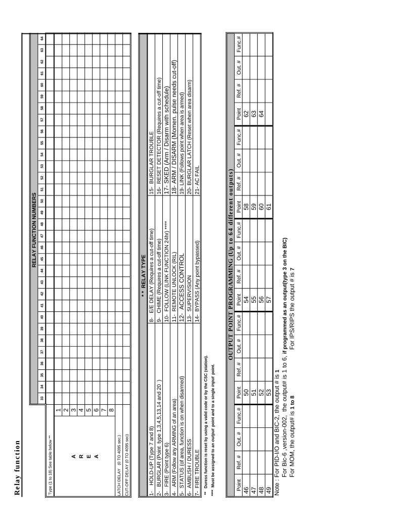
Rel
ay f
un
ctio
n
RE
LA
Y F
UN
CT
ION
NU
MB
ER
S33
34
35
36
37
38
39
40
41
42
43
44
45
46
47
48
49
50
51
52
53
54
55
56
57
58
59
60
61
62
63
64
Typ
e (1
to 1
8) S
ee ta
ble
belo
w *
*
1 2A
3
R
4E
5
A
6 7 8LA
TC
H D
ELA
Y
(0 T
O 4
095
sec.
)
CU
T-O
FF
DE
LAY
(0
TO
409
5 se
c)
* *
RE
LA
Y T
YP
E
1-
HO
LD-U
P (
Typ
e 7
and
8)
8-
E/E
DE
LAY
(R
equi
res
a cu
t-of
f tim
e)
15-
BU
RG
LAR
TR
OU
BLE
2-
BU
RG
LAR
(P
oint
typ
e 1,
3,4,
5,13
,14
and
20 )
9-
C
HIM
E (
Req
uire
s a
cut-
off t
ime)
16
- R
ES
ET
DE
TE
CT
OR
(R
equi
res
a cu
t-of
f tim
e)3-
F
IRE
(P
oint
type
6)
10-
FO
LLO
W (
LIN
K F
UN
CT
ION
24h
r) *
***
17-
SK
ED
(A
rm /
Dis
arm
with
sch
edul
e)4-
A
RM
(F
ollo
w a
ny A
RM
ING
of a
n ar
ea)
11-
RE
MO
TE
UN
LOC
K (
RIL
) 18
- A
RM
/ D
ISA
RM
(M
omen
. pul
se n
eeds
cut
-off)
5- S
TA
TU
S (
of a
rea,
func
tion
is o
n w
hen
disa
rmed
) 12
- A
CC
ES
S C
ON
TR
OL
19-
LIN
K (
Fol
low
s po
int w
hen
area
is a
rmed
)6-
AM
BU
SH
/ D
UR
ES
S
13-
SU
PE
RV
ISIO
N
20-
BU
RG
LAR
LA
TC
H (
Res
et w
hen
area
dis
arm
)
7- F
IRE
TR
OU
BLE
14
- B
YP
AS
S (
Any
poi
nt b
ypas
sed)
21
- A
C F
AIL
**
Du
ress
fu
nct
ion
is r
eset
by
usi
ng
a v
alid
co
de
or
by
the
CS
C (
stat
ion
).
****
Mu
st b
e as
sig
ned
to
an
ou
tpu
t p
oin
t an
d t
o a
sin
gle
inp
ut
po
int.
OU
TPU
T P
OIN
T P
RO
GR
AM
MIN
G (U
p t
o 6
4 d
iffe
rent
outp
uts
)P
oint
R
ef. #
O
ut. #
F
unc.
# P
oint
R
ef. #
O
ut. #
F
unc.
# P
oint
R
ef. #
O
ut. #
F
unc.
# P
oint
R
ef. #
O
ut. #
F
unc.
# P
oint
R
ef. #
O
ut. #
F
unc.
#46
50
54
58
62
47
51
55
59
6348
52
56
60
64
49
53
57
61N
ote
: For
PID
-I/O
and
BIC
-2, t
he o
utpu
t # is
1
F
or B
ic-6
,ver
sion
-002
, th
e ou
tput
# is
1 to
6, i
f p
rog
ram
med
as
an o
utp
ut(
typ
e 3
on
th
e B
IC)
For
MO
M, t
he o
utpu
t# is
1 t
o 8
F
or IP
S/R
IPS
the
outp
ut #
is 7
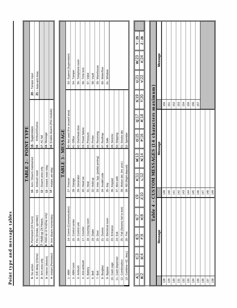
Poin
t ty
pe
and m
essa
ge t
able
s
TA
BLE
2-
PO
INT
TY
PE
0-
No
actio
n 5-
Per
man
ent (
24 h
ours
) 10
- A
rm /
Dis
arm
mai
ntai
ned
15 -
Sup
ervi
sion
20
-T
ampe
r in
put
1-E
/E d
elay
(C
him
e)
6- F
ire (
Sm
oke,
spr
inkl
er)
11-
Am
bush
res
et
16-
A
mbu
sh/D
ures
s 21
-A
uto-
arm
Are
a
2-A
rm a
rea
only
7-
Hol
d-up
24
Hou
rs.
12 -
Dis
arm
are
a on
ly
17-
AC
fail
3-In
terio
r (M
otio
n)8-
Hol
d-up
12
hrs(
Day
onl
y)13
-In
stan
t, re
set r
elay
18-
Mes
sage
4-In
stan
t (P
erim
etor
) 9-
Arm
dis
arm
mom
enta
ry14
-In
stan
t, se
t rel
ay19
- E
nabl
e di
sarm
(P
im m
odul
e)
TA
BLE
3-
ME
SSA
GE
1-A
BM
14
-C
omm
(C
omm
unic
atio
n)
27-
Fre
ezer
40
- N
ot u
sed
(For
unu
sed
area
) 53
-S
uper
vi (
Sup
ervi
sion
)
2-A
BM
roo
m
15-
Con
trol
cen
ter
28-
Gar
age
41-
Offi
ce
54-
Tam
per
3-A
mbu
sh
16-
Con
trol
uni
t 29
-G
ener
ator
42
- O
verh
ead
door
55
-T
elep
hone
roo
m
4-A
nti-a
mbu
sh
17-
Cou
nter
30
-H
ead
sw
43-
Pow
er fa
ilure
56
-T
ime
lock
5-B
atte
ry
18-
Cou
ntin
g ro
om
31-
Hea
t 44
- P
ress
ure
57-
Val
ve
6-B
ell
19-
Dia
ler
32-
Hol
d-up
45
- P
rinte
r 58
-V
ault
7-B
olt
20-
Doo
r 33
-In
ter.
byp
. (pa
rtia
l arm
ing)
46
- R
ecei
ving
59
-W
areh
ouse
8-B
urgl
ary
21-
Dur
ess
34-
Inva
lid c
ode
47-
Roo
ftrap
60
-W
ater
flow
9-B
ypas
s 22
-E
lect
rical
roo
m
35-
Key
48
- S
afe
61-
Win
dow
10-
Cas
h ca
ge
23-
Ent
ranc
e 36
-K
eypa
d 49
- S
eism
ic
11-
Cas
h di
spen
ser
24-
Exi
t 37
-M
ini-s
afe
50-
Shi
ppin
g
12-
Com
bina
ition
25
-F
ail (
Sei
smic
fail
to te
st)
38-
Mot
ion
det.
(Int
. pro
t.)
51-
Sm
oke
det.
13-
Com
bine
+(C
. des
j.)
26-
Fire
39
-N
D (
Nig
ht d
epos
it)
52-
Spr
inkl
er
A1
C3
E5
G7
I9
K11
M
13
O15
Q
17
S19
U
21
W23
Y
: 2
5B
2 D
4 F
6 H
8 J
10
L12
N
14
P16
R
18
T20
V
22
X24
Z
: 2
6
Tab
le 4
- C
UST
OM
ME
SSA
GE
S (14 c
har
acte
rs m
axim
um
)M
essa
ge
Mes
sag
e -
M
essa
ge
128
139
150
129
140
151
130
141
152
131
142
153
132
143
154
133
144
155
134
145
156
135
146
157
136
147
13
7 14
8
138
149
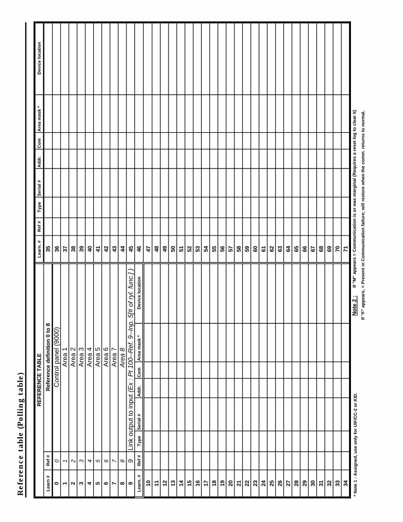
Ref
eren
ce t
able
(Poll
ing
table
)
RE
FE
RE
NC
E T
AB
LE
L
earn
. #
Ref
#
Typ
e S
eria
l #
Ad
dr.
C
om
A
rea
mas
k *
Dev
ice
loca
tio
n
Lea
rn #
R
ef #
R
efer
ence
def
init
ion
0 t
o 8
35
0 0
Con
trol
pan
el (
9000
) 36
1 1
Are
a 1
372
2
Are
a 2
383
3
Are
a 3
394
4
Are
a 4
405
5
Are
a 5
416
6
Are
a 6
427
7
Are
a 7
438
8
Are
a 8
449
9 Li
nk o
utpu
t to
inpu
t (E
x :
Pt
100--
Ref. 9
--In
p.
5[#
of
ryl.
func.
] )
45L
earn
. #
Ref
#
Typ
e S
eria
l #
Ad
dr.
C
om
A
rea
mas
k *
Dev
ice
loca
tio
n
46
10
47
11
48
12
49
13
50
14
51
15
52
16
53
17
54
18
55
19
56
20
57
21
58
22
59
23
60
24
61
25
62
26
63
27
64
28
65
29
66
30
67
31
68
32
69
33
7034
71
* N
ote
1 :
Ass
ign
ed, u
se o
nly
fo
r U
IF/C
C-2
or
KID
. N
ote
2 :
If "
M"
app
ears
= C
om
mu
nic
atio
n is
or
was
mar
gin
al (
Req
uir
es a
res
et lo
g t
o c
lear
it)
If
"F"
app
ears
, = P
rese
nt
in C
om
mu
nic
atio
n f
ailu
re;
will
res
tore
wh
en t
he
com
m. r
etu
rns
to n
orm
al.
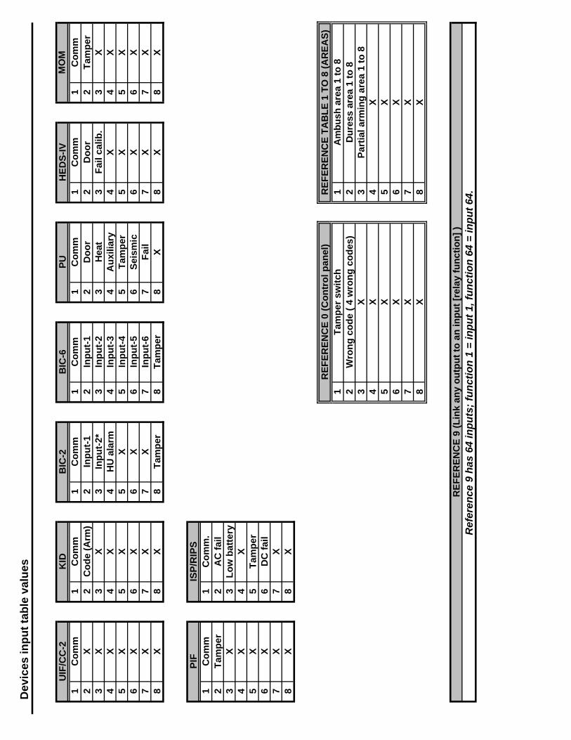
Dev
ices
inp
ut
tab
le v
alu
es
UIF
/CC
-2
KID
B
IC-2
B
IC-6
P
U
HE
DS
-IV
M
OM
1 C
om
m
1 C
om
m
1 C
om
m
1 C
om
m
1 C
om
m
1 C
om
m
1 C
om
m2
X
2 C
od
e (A
rm)
2 In
pu
t-1
2 In
pu
t-1
2 D
oo
r 2
Do
or
2 T
amp
er3
X
3 X
3
Inp
ut-
2*
3 In
pu
t-2
3 H
eat
3 F
ail c
alib
. 3
X4
X
4 X
4
HU
ala
rm
4 In
pu
t-3
4 A
uxi
liary
4
X
4 X
5 X
5
X
5 X
5
Inp
ut-
4 5
Tam
per
5
X
5 X
6 X
6
X
6 X
6
Inp
ut-
5 6
Sei
smic
6
X
6 X
7 X
7
X
7 X
7
Inp
ut-
6 7
Fai
l 7
X
7 X
8 X
8
X
8 T
amp
er
8 T
amp
er
8 X
8
X
8 X
PIF
IS
P/R
IPS
1 C
om
m
1 C
om
m.
2 T
amp
er
2 A
C f
ail
3 X
3
Lo
w b
atte
ry4
X
4 X
5 X
5
Tam
per
6 X
6
DC
fai
l7
X
7 X
8 X
8
X
RE
FE
RE
NC
E 0
(C
on
tro
l pan
el)
RE
FE
RE
NC
E T
AB
LE
1 T
O 8
(A
RE
AS
)1
Tam
per
sw
itch
1
Am
bu
sh a
rea
1 to
82
Wro
ng
co
de
( 4
wro
ng
co
des
) 2
Du
ress
are
a 1
to 8
3 X
3
Par
tial
arm
ing
are
a 1
to 8
4 X
4
X5
X
5 X
6 X
6
X7
X
7 X
8 X
8
X
RE
FE
RE
NC
E 9
(L
ink
any
ou
tpu
t to
an
inp
ut
[rel
ay f
un
ctio
n]
)R
efer
ence
9 h
as 6
4 in
pu
ts;
fun
ctio
n 1
= in
pu
t 1,
fu
nct
ion
64
= in
pu
t 64
.

Poin
t pro
gram
min
g
Po
int
Dev
ice
Are
a M
ES
SA
GE
T
ype
Op
tio
n
Kid
LE
D
Lin
k fu
nc.
# R
ef #
In
pu
t #
Dev
ice
nam
e #
# M
essa
ge
1 (F
rom
tab
le 3
or
4)
# M
essa
ge
2 (F
rom
tab
le 3
or
4)
1 to
22
(to
tal)
L
og
#
(1 t
o 4
)
1 2 3 4 5 6 7 8 9 10
11
12
13
14
15
16
17
18
19
20
21
22
23
24
25
32 =
Lo
cal o
nly
8 =
Day
an
nu
nci
atio
n o
n C
C-2
1 =
Byp
ass
64 =
Po
int
typ
e d
epen
den
t
2 =
Fo
rce
arm
Op
tio
ns
16 =
So
un
d o
n C
C-2
4 =
Cle
ar t
o A
rm
128=
Au
tom
atic
byp
ass
rese
t
P.1
4-34
(pts
)

Poin
t pro
gram
min
g (c
on
tin
ued
)
Po
int
Dev
ice
Are
a M
ES
SA
GE
T
ype
Op
tio
n
Kid
LE
D
Lin
k fu
nc.
# R
ef #
In
pu
t #
Dev
ice
nam
e #
# M
essa
ge
1 (F
rom
tab
le 3
or
4)
# M
essa
ge
2 (F
rom
tab
le 3
or
4)
1 to
22
(to
tal)
L
og
#
(1 t
o 4
) (F
ollo
w)
26
27
28
29
30
31
32
33
34
35
36
37
38
39
40
41
42
43
44
45
46
47
48
49
50
64 =
Po
int
typ
e d
epen
den
tO
pti
on
s1
= B
ypas
s 4
= C
lear
to
Arm
16
= S
ou
nd
on
CC
-2
128=
Au
tom
atic
byp
ass
rese
t2
= F
orc
e ar
m
8 =
Day
an
nu
nci
atio
n o
n C
C-2
32
= L
oca
l on
ly
P.1
4-34
(pts
)
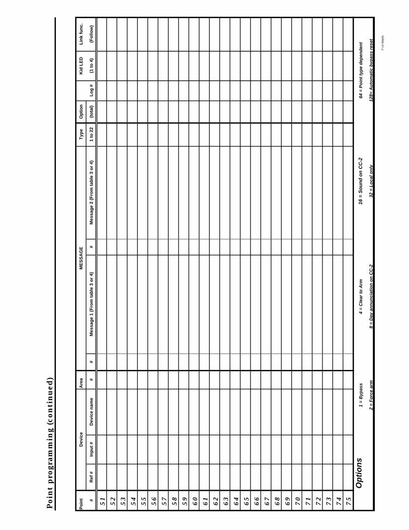
Poin
t pro
gram
min
g (c
on
tin
ued
)
Po
int
Dev
ice
Are
a M
ES
SA
GE
T
ype
Op
tio
n
Kid
LE
D
Lin
k fu
nc.
# R
ef #
In
pu
t #
Dev
ice
nam
e #
# M
essa
ge
1 (F
rom
tab
le 3
or
4)
# M
essa
ge
2 (F
rom
tab
le 3
or
4)
1 to
22
(to
tal)
L
og
#
(1 t
o 4
) (F
ollo
w)
51
52
53
54
55
56
57
58
59
60
61
62
63
64
65
66
67
68
69
70
71
72
73
74
75
Op
tio
ns
1 =
Byp
ass
4 =
Cle
ar t
o A
rm
16 =
So
un
d o
n C
C-2
64
= P
oin
t ty
pe
dep
end
ent
2 =
Fo
rce
arm
8
= D
ay a
nn
un
ciat
ion
on
CC
-2
32 =
Lo
cal o
nly
12
8= A
uto
mat
ic b
ypas
s re
set
P.1
4-34
(pts
)

Poin
t pro
gram
min
g (c
on
tin
ued
)
Po
int
Dev
ice
Are
a M
ES
SA
GE
T
ype
Op
tio
n
Kid
LE
D
Lin
k fu
nc.
# R
ef #
In
pu
t #
Dev
ice
nam
e #
# M
essa
ge
1 (F
rom
tab
le 3
or
4)
# M
essa
ge
2 (F
rom
tab
le 3
or
4)
1 to
22
(to
tal)
L
og
#
(1 t
o 4
) (F
ollo
w)
76
77
78
79
80
81
82
83
84
85
86
87
88
89
90
91
92
93
94
95
96
97
98
99
10
0
Op
tio
ns
1 =
Byp
ass
4 =
Cle
ar t
o A
rm
16 =
So
un
d o
n C
C-2
64
= P
oin
t ty
pe
dep
end
ent
2 =
Fo
rce
arm
8
= D
ay a
nn
un
ciat
ion
on
CC
-2
32 =
Lo
cal o
nly
12
8= A
uto
mat
ic b
ypas
s re
set
P.1
4-34
(pts
)

Poin
t pro
gram
min
g (c
on
tin
ued
)
Po
int
Dev
ice
Are
a M
ES
SA
GE
T
ype
Op
tio
n
Kid
LE
D
Lin
k fu
nc.
# R
ef #
In
pu
t #
Dev
ice
nam
e #
# M
essa
ge
1 (F
rom
tab
le 3
or
4)
# M
essa
ge
2 (F
rom
tab
le 3
or
4)
1 to
22
(to
tal)
L
og
#
(1 t
o 4
) (F
ollo
w)
10
1
10
2
10
3
10
4
10
5
10
6
10
7
10
8
10
9
11
0
11
1
11
2
11
3
11
4
11
5
11
6
11
7
11
8
11
9
12
0
12
1
12
2
12
3
12
41
25
Op
tio
ns
1 =
Byp
ass
4 =
Cle
ar t
o A
rm
16 =
So
un
d o
n C
C-2
64
= P
oin
t ty
pe
dep
end
ent
2 =
Fo
rce
arm
8
= D
ay a
nn
un
ciat
ion
on
CC
-2
32 =
Lo
cal o
nly
12
8= A
uto
mat
ic b
ypas
s re
set
P.1
4-34
(pts
)
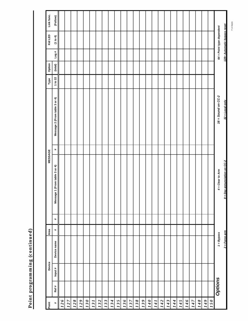
Poin
t pro
gram
min
g (c
on
tin
ued
)
Po
int
Dev
ice
Are
a M
ES
SA
GE
T
ype
Op
tio
n
Kid
LE
D
Lin
k fu
nc.
# R
ef #
In
pu
t #
Dev
ice
nam
e #
# M
essa
ge
1 (F
rom
tab
le 3
or
4)
# M
essa
ge
2 (F
rom
tab
le 3
or
4)
1 to
22
(to
tal)
L
og
#
(1 t
o 4
) (F
ollo
w)
12
6
12
7
12
8
12
9
13
0
13
1
13
2
13
3
13
4
13
5
13
6
13
7
13
8
13
9
14
0
14
1
14
2
14
3
14
4
14
5
14
6
14
7
14
8
14
91
50
Op
tio
ns
1 =
Byp
ass
4 =
Cle
ar t
o A
rm
16 =
So
un
d o
n C
C-2
64
= P
oin
t ty
pe
dep
end
ent
2 =
Fo
rce
arm
8
= D
ay a
nn
un
ciat
ion
on
CC
-2
32 =
Lo
cal o
nly
12
8= A
uto
mat
ic b
ypas
s re
set
P.1
4-34
(pts
)

Poin
t pro
gram
min
g (c
on
tin
ued
)
Po
int
Dev
ice
Are
a M
ES
SA
GE
T
ype
Op
tio
n
Kid
LE
D
Lin
k fu
nc.
# R
ef #
In
pu
t #
Dev
ice
nam
e #
# M
essa
ge
1 (F
rom
tab
le 3
or
4)
# M
essa
ge
2 (F
rom
tab
le 3
or
4)
1 to
22
(to
tal)
L
og
#
(1 t
o 4
) (F
ollo
w)
15
1
15
2
15
3
15
4
15
5
15
6
15
7
15
8
15
9
16
0
16
1
16
2
16
3
16
4
16
5
16
6
16
7
16
8
16
9
17
0
17
1
17
2
17
3
17
41
75
Op
tio
ns
1 =
Byp
ass
4 =
Cle
ar t
o A
rm
16 =
So
un
d o
n C
C-2
64
= P
oin
t ty
pe
dep
end
ent
2 =
Fo
rce
arm
8
= D
ay a
nn
un
ciat
ion
on
CC
-2
32 =
Lo
cal o
nly
12
8= A
uto
mat
ic b
ypas
s re
set
P.1
4-34
(pts
)

Poin
t pro
gram
min
g (c
on
tin
ued
)
Po
int
Dev
ice
Are
a M
ES
SA
GE
T
ype
Op
tio
n
Kid
LE
D
Lin
k fu
nc.
Ref
#
Inp
ut
# D
evic
e n
ame
# #
Mes
sag
e 1
(Fro
m t
able
3 o
r 4)
#
Mes
sag
e 2
(Fro
m t
able
3 o
r 4)
1
to 2
2 (t
ota
l)
Lo
g #
(1
to
4)
(Fo
llow
)
17
6
17
7
17
8
17
9
18
0
18
1
18
2
18
3
18
4
18
5
18
6
18
7
18
8
18
9
19
0
19
1
19
2
19
3
19
4
19
5
19
6
19
7
19
8
19
92
00
Op
tio
ns
1 =
Byp
ass
4 =
Cle
ar t
o A
rm
16 =
So
un
d o
n C
C-2
64
= P
oin
t ty
pe
dep
end
ent
2 =
Fo
rce
arm
8
= D
ay a
nn
un
ciat
ion
on
CC
-2
32 =
Lo
cal o
nly
12
8= A
uto
mat
ic b
ypas
s re
set
P.1
4-34
(pts
)

Poin
t pro
gram
min
g (c
on
tin
ued
)
Po
int
Dev
ice
Are
a M
ES
SA
GE
T
ype
Op
tio
n
Kid
LE
D
Lin
k fu
nc.
Ref
#
Inp
ut
# D
evic
e n
ame
# #
Mes
sag
e 1
(Fro
m t
able
3 o
r 4)
#
Mes
sag
e 2
(Fro
m t
able
3 o
r 4)
1
to 2
2 (t
ota
l)
Lo
g #
(1
to
4)
(Fo
llow
)
20
1
20
2
20
3
20
4
20
5
20
6
20
7
20
8
20
9
21
0
21
1
21
2
21
3
21
4
21
5
21
6
21
7
21
8
21
9
22
0
22
1
22
2
22
3
22
42
25
Op
tio
ns
1 =
Byp
ass
4 =
Cle
ar t
o A
rm
16 =
So
un
d o
n C
C-2
64
= P
oin
t ty
pe
dep
end
ent
2 =
Fo
rce
arm
8
= D
ay a
nn
un
ciat
ion
on
CC
-2
32 =
Lo
cal o
nly
12
8= A
uto
mat
ic b
ypas
s re
set
P.1
4-34
(pts
)
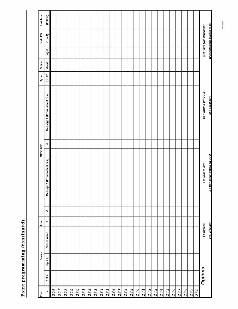
Poin
t pro
gram
min
g (c
on
tin
ued
)
Po
int
Dev
ice
Are
a M
ES
SA
GE
T
ype
Op
tio
n
Kid
LE
D
Lin
k fu
nc.
# R
ef #
In
pu
t #
Dev
ice
nam
e #
# M
essa
ge
1 (F
rom
tab
le 3
or
4)
# M
essa
ge
2 (F
rom
tab
le 3
or
4)
1 to
22
(to
tal)
L
og
#
(1 t
o 4
) (F
ollo
w)
22
6
22
7
22
8
22
9
23
0
23
1
23
2
23
3
23
4
23
5
23
6
23
7
23
8
23
9
24
0
24
1
24
2
24
3
24
4
24
5
24
6
24
7
24
8
24
92
50
Op
tio
ns
1 =
Byp
ass
4 =
Cle
ar t
o A
rm
16 =
So
un
d o
n C
C-2
64
= P
oin
t ty
pe
dep
end
ent
2 =
Fo
rce
arm
8
= D
ay a
nn
un
ciat
ion
on
CC
-2
32 =
Lo
cal o
nly
12
8= A
uto
mat
ic b
ypas
s re
set
P.1
4-34
(pts
)

Poin
t pro
gram
min
g (c
on
tin
ued
)
Po
int
Dev
ice
Are
a M
ES
SA
GE
T
ype
Op
tio
n
Kid
LE
D
Lin
k fu
nc.
# R
ef #
In
pu
t #
Dev
ice
nam
e #
# M
essa
ge
1 (F
rom
tab
le 3
or
4)
# M
essa
ge
2 (F
rom
tab
le 3
or
4)
1 to
22
(to
tal)
L
og
#
(1 t
o 4
) (F
ollo
w)
25
1
25
2
25
3
25
4
25
5
25
6
25
7
25
8
25
9
26
0
26
1
26
2
26
3
26
4
26
5
26
6
26
7
26
8
26
9
27
0
27
1
27
2
27
3
27
42
75
Op
tio
ns
1 =
Byp
ass
4 =
Cle
ar t
o A
rm
16 =
So
un
d o
n C
C-2
64
= P
oin
t ty
pe
dep
end
ent
2 =
Fo
rce
arm
8
= D
ay a
nn
un
ciat
ion
on
CC
-2
32 =
Lo
cal o
nly
12
8= A
uto
mat
ic b
ypas
s re
set
P.1
4-34
(pts
)

Poin
t pro
gram
min
g (c
on
tin
ued
)
Po
int
Dev
ice
Are
a M
ES
SA
GE
T
ype
Op
tio
n
Kid
LE
D
Lin
k fu
nc.
# R
ef #
In
pu
t #
Dev
ice
nam
e #
# M
essa
ge
1 (F
rom
tab
le 3
or
4)
# M
essa
ge
2 (F
rom
tab
le 3
or
4)
1 to
22
(to
tal)
L
og
#
(1 t
o 4
) (F
ollo
w)
27
6
27
7
27
8
27
9
28
0
28
1
28
2
28
3
28
4
28
5
28
6
28
7
28
8
28
9
29
0
29
1
29
2
29
3
29
4
29
5
29
6
29
7
29
8
29
93
00
Op
tio
ns
1 =
Byp
ass
4 =
Cle
ar t
o A
rm
16 =
So
un
d o
n C
C-2
64
= P
oin
t ty
pe
dep
end
ent
2 =
Fo
rce
arm
8
= D
ay a
nn
un
ciat
ion
on
CC
-2
32 =
Lo
cal o
nly
12
8= A
uto
mat
ic b
ypas
s re
set
P.1
4-34
(pts
)

Poin
t pro
gram
min
g (c
on
tin
ued
)
Po
int
Dev
ice
Are
a M
ES
SA
GE
T
ype
Op
tio
n
Kid
LE
D
Lin
k fu
nc.
# R
ef #
In
pu
t #
Dev
ice
nam
e #
# M
essa
ge
1 (F
rom
tab
le 3
or
4)
# M
essa
ge
2 (F
rom
tab
le 3
or
4)
1 to
22
(to
tal)
L
og
#
(1 t
o 4
) (F
ollo
w)
30
1
30
2
30
3
30
4
30
5
30
6
30
7
30
8
30
9
31
0
31
1
31
2
31
3
31
4
31
5
31
6
31
7
31
8
31
9
32
0
32
1
32
2
32
3
32
43
25
Op
tio
ns
1 =
Byp
ass
4 =
Cle
ar t
o A
rm
16 =
So
un
d o
n C
C-2
64
= P
oin
t ty
pe
dep
end
ent
2 =
Fo
rce
arm
8
= D
ay a
nn
un
ciat
ion
on
CC
-2
32 =
Lo
cal o
nly
12
8= A
uto
mat
ic b
ypas
s re
set
P.1
4-34
(pts
)

Poin
t pro
gram
min
g (c
on
tin
ued
)
Po
int
Dev
ice
Are
a M
ES
SA
GE
T
ype
Op
tio
n
Kid
LE
D
Lin
k fu
nc.
# R
ef #
In
pu
t #
Dev
ice
nam
e #
# M
essa
ge
1 (F
rom
tab
le 3
or
4)
# M
essa
ge
2 (F
rom
tab
le 3
or
4)
1 to
22
(to
tal)
L
og
#
(1 t
o 4
) (F
ollo
w)
32
6
32
7
32
8
32
9
33
0
33
1
33
2
33
3
33
4
33
5
33
6
33
7
33
8
33
9
34
0
34
1
34
2
34
3
34
4
34
5
34
6
34
7
34
8
34
93
50
Op
tio
ns
1 =
Byp
ass
4 =
Cle
ar t
o A
rm
16 =
So
un
d o
n C
C-2
64
= P
oin
t ty
pe
dep
end
ent
2 =
Fo
rce
arm
8
= D
ay a
nn
un
ciat
ion
on
CC
-2
32 =
Lo
cal o
nly
12
8= A
uto
mat
ic b
ypas
s re
set
P.1
4-34
(pts
)

Poin
t pro
gram
min
g (c
on
tin
ued
)
Po
int
Dev
ice
Are
a M
ES
SA
GE
T
ype
Op
tio
n
Kid
LE
D
Lin
k fu
nc.
# R
ef #
In
pu
t #
Dev
ice
nam
e #
# M
essa
ge
1 (F
rom
tab
le 3
or
4)
# M
essa
ge
2 (F
rom
tab
le 3
or
4)
1 to
22
(to
tal)
L
og
#
(1 t
o 4
) (F
ollo
w)
35
1
35
2
35
3
35
4
35
5
35
6
35
7
35
8
35
9
36
0
36
1
36
2
36
3
36
4
36
5
36
6
36
7
36
8
36
9
37
0
37
1
37
2
37
3
37
43
75
Op
tio
ns
1 =
Byp
ass
4 =
Cle
ar t
o A
rm
16 =
So
un
d o
n C
C-2
64
= P
oin
t ty
pe
dep
end
ent
2 =
Fo
rce
arm
8
= D
ay a
nn
un
ciat
ion
on
CC
-2
32 =
Lo
cal o
nly
12
8= A
uto
mat
ic b
ypas
s re
set
P.1
4-34
(pts
)

Poin
t pro
gram
min
g (c
on
tin
ued
)
Po
int
Dev
ice
Are
a M
ES
SA
GE
T
ype
Op
tio
n
Kid
LE
D
Lin
k fu
nc.
# R
ef #
In
pu
t #
Dev
ice
nam
e #
# M
essa
ge
1 (F
rom
tab
le 3
or
4)
# M
essa
ge
2 (F
rom
tab
le 3
or
4)
1 to
22
(to
tal)
L
og
#
(1 t
o 4
) (F
ollo
w)
37
6
37
7
37
8
37
9
38
0
38
1
38
2
38
3
38
4
38
5
38
6
38
7
38
8
38
9
39
0
39
1
39
2
39
3
39
4
39
5
39
6
39
7
39
8
39
94
00
Op
tio
ns
1 =
Byp
ass
4 =
Cle
ar t
o A
rm
16 =
So
un
d o
n C
C-2
64
= P
oin
t ty
pe
dep
end
ent
2 =
Fo
rce
arm
8
= D
ay a
nn
un
ciat
ion
on
CC
-2
32 =
Lo
cal o
nly
12
8= A
uto
mat
ic b
ypas
s re
set
P.1
4-34
(pts
)

Poin
t pro
gram
min
g (c
on
tin
ued
)
Po
int
Dev
ice
Are
a M
ES
SA
GE
T
ype
Op
tio
n
Kid
LE
D
Lin
k fu
nc.
# R
ef #
In
pu
t #
Dev
ice
nam
e #
# M
essa
ge
1 (F
rom
tab
le 3
or
4)
# M
essa
ge
2 (F
rom
tab
le 3
or
4)
1 to
22
(to
tal)
L
og
#
(1 t
o 4
) (F
ollo
w)
40
1
40
2
40
3
40
4
40
5
40
6
40
7
40
8
40
9
41
0
41
1
41
2
41
3
41
4
41
5
41
6
41
7
41
8
41
9
42
0
42
1
42
2
42
3
42
44
25
Op
tio
ns
1 =
Byp
ass
4 =
Cle
ar t
o A
rm
16 =
So
un
d o
n C
C-2
64
= P
oin
t ty
pe
dep
end
ent
2 =
Fo
rce
arm
8
= D
ay a
nn
un
ciat
ion
on
CC
-2
32 =
Lo
cal o
nly
12
8= A
uto
mat
ic b
ypas
s re
set
P.1
4-34
(pts
)
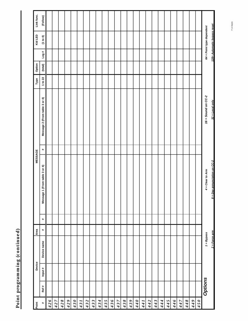
Poin
t pro
gram
min
g (c
on
tin
ued
)
Po
int
Dev
ice
Are
a M
ES
SA
GE
T
ype
Op
tio
n
Kid
LE
D
Lin
k fu
nc.
# R
ef #
In
pu
t #
Dev
ice
nam
e #
# M
essa
ge
1 (F
rom
tab
le 3
or
4)
# M
essa
ge
2 (F
rom
tab
le 3
or
4)
1 to
22
(to
tal)
L
og
#
(1 t
o 4
) (F
ollo
w)
42
6
42
7
42
8
42
9
43
0
43
1
43
2
43
3
43
4
43
5
43
6
43
7
43
8
43
9
44
0
44
1
44
2
44
3
44
4
44
5
44
6
44
7
44
8
44
94
50
Op
tio
ns
1 =
Byp
ass
4 =
Cle
ar t
o A
rm
16 =
So
un
d o
n C
C-2
64
= P
oin
t ty
pe
dep
end
ent
2 =
Fo
rce
arm
8
= D
ay a
nn
un
ciat
ion
on
CC
-2
32 =
Lo
cal o
nly
12
8= A
uto
mat
ic b
ypas
s re
set
P.1
4-34
(pts
)

Poin
t pro
gram
min
g (c
on
tin
ued
)
Po
int
Dev
ice
Are
a M
ES
SA
GE
T
ype
Op
tio
n
Kid
LE
D
Lin
k fu
nc.
# R
ef #
In
pu
t #
Dev
ice
nam
e #
# M
essa
ge
1 (F
rom
tab
le 3
or
4)
# M
essa
ge
2 (F
rom
tab
le 3
or
4)
1 to
22
(to
tal)
L
og
#
(1 t
o 4
) (F
ollo
w)
45
1
45
2
45
3
45
4
45
5
45
6
45
7
45
8
45
9
46
0
46
1
46
2
46
3
46
4
46
5
46
6
46
7
46
8
46
9
47
0
47
1
47
2
47
34
74
Op
tio
ns
1 =
Byp
ass
4 =
Cle
ar t
o A
rm
16 =
So
un
d o
n C
C-2
64
= P
oin
t ty
pe
dep
end
ent
2 =
Fo
rce
arm
8
= D
ay a
nn
un
ciat
ion
on
CC
-2
32 =
Lo
cal o
nly
12
8= A
uto
mat
ic b
ypas
s re
set
P.1
4-34
(pts
)
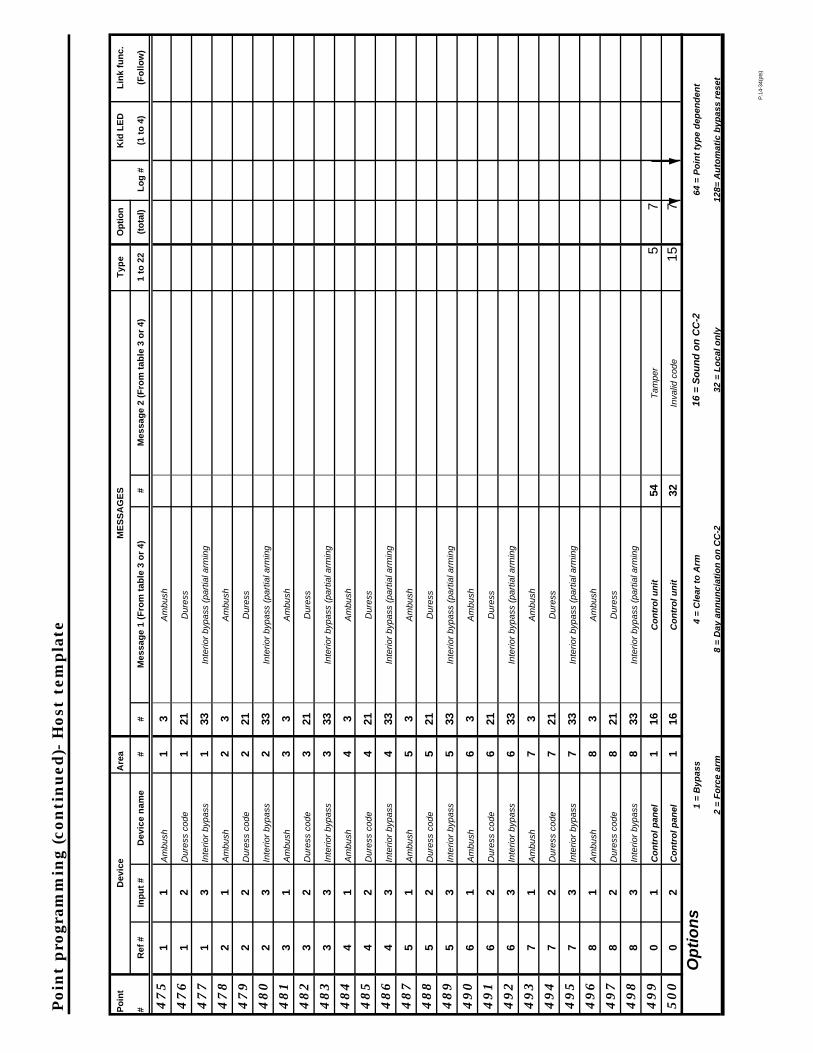
Poin
t pro
gram
min
g (c
on
tin
ued
)- H
ost
tem
pla
te
Po
int
Dev
ice
Are
a M
ES
SA
GE
S
Typ
e O
pti
on
K
id L
ED
L
ink
fun
c.
# R
ef #
In
pu
t #
Dev
ice
nam
e #
# M
essa
ge
1 (F
rom
tab
le 3
or
4)
# M
essa
ge
2 (F
rom
tab
le 3
or
4)
1 to
22
(to
tal)
L
og
#
(1 t
o 4
) (F
ollo
w)
47
51
1 A
mb
ush
1
3 A
mb
ush
47
61
2 D
ure
ss c
od
e
1 21
D
ure
ss
47
71
3 In
teri
or
byp
ass
1
33
Inte
rio
r b
ypa
ss (
pa
rtia
l arm
ing
47
82
1 A
mb
ush
2
3 A
mb
ush
47
92
2 D
ure
ss c
od
e
2 21
D
ure
ss
48
02
3 In
teri
or
byp
ass
2
33
Inte
rio
r b
ypa
ss (
pa
rtia
l arm
ing
48
13
1 A
mb
ush
3
3 A
mb
ush
48
23
2 D
ure
ss c
od
e
3 21
D
ure
ss
48
33
3 In
teri
or
byp
ass
3
33
Inte
rio
r b
ypa
ss (
pa
rtia
l arm
ing
48
44
1 A
mb
ush
4
3 A
mb
ush
48
54
2 D
ure
ss c
od
e
4 21
D
ure
ss
48
64
3 In
teri
or
byp
ass
4
33
Inte
rio
r b
ypa
ss (
pa
rtia
l arm
ing
48
75
1 A
mb
ush
5
3 A
mb
ush
48
85
2 D
ure
ss c
od
e
5 21
D
ure
ss
48
95
3 In
teri
or
byp
ass
5
33
Inte
rio
r b
ypa
ss (
pa
rtia
l arm
ing
49
06
1 A
mb
ush
6
3 A
mb
ush
49
16
2 D
ure
ss c
od
e
6 21
D
ure
ss
49
26
3 In
teri
or
byp
ass
6
33
Inte
rio
r b
ypa
ss (
pa
rtia
l arm
ing
49
37
1 A
mb
ush
7
3 A
mb
ush
49
47
2 D
ure
ss c
od
e
7 21
D
ure
ss
49
57
3 In
teri
or
byp
ass
7
33
Inte
rio
r b
ypa
ss (
pa
rtia
l arm
ing
49
68
1 A
mb
ush
8
3 A
mb
ush
49
78
2 D
ure
ss c
od
e
8 21
D
ure
ss
49
88
3 In
teri
or
byp
ass
8
33
Inte
rio
r b
ypa
ss (
pa
rtia
l arm
ing
49
90
1 C
on
tro
l pan
el
1 16
C
on
tro
l un
it
54
Tam
per
5 7
50
0
0 2
Co
ntr
ol p
anel
1
16
Co
ntr
ol u
nit
32
In
valid
co
de
15
7
Op
tio
ns
1 =
Byp
ass
4 =
Cle
ar t
o A
rm
16 =
So
un
d o
n C
C-2
64
= P
oin
t ty
pe
dep
end
ent
2 =
Fo
rce
arm
8
= D
ay a
nn
un
ciat
ion
on
CC
-2
32 =
Lo
cal o
nly
12
8= A
uto
mat
ic b
ypas
s re
set
P.1
4-34
(pts
)
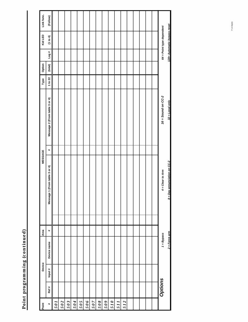
Poin
t pro
gram
min
g (c
on
tin
ued
)
Po
int
Dev
ice
Are
a M
ES
SA
GE
T
ype
Op
tio
n
Kid
LE
D
Lin
k fu
nc.
# R
ef #
In
pu
t #
Dev
ice
nam
e #
Mes
sag
e 1
(Fro
m t
able
3 o
r 4)
#
Mes
sag
e 2
(Fro
m t
able
3 o
r 4)
1
to 2
2 (t
ota
l)
Lo
g #
(1
to
4)
(Fo
llow
)
50
1
50
2
50
3
50
4
50
5
50
6
50
7
50
8
50
9
51
0
51
1
51
2
Op
tio
ns
1 =
Byp
ass
4 =
Cle
ar t
o A
rm
16 =
So
un
d o
n C
C-2
64
= P
oin
t ty
pe
dep
end
ent
2 =
Fo
rce
arm
8
= D
ay a
nn
un
ciat
ion
on
CC
-2
32 =
Lo
cal o
nly
12
8= A
uto
mat
ic b
ypas
s re
set
P.1
4-34
(pts
)

Inst
alla
tio
n la
you
t
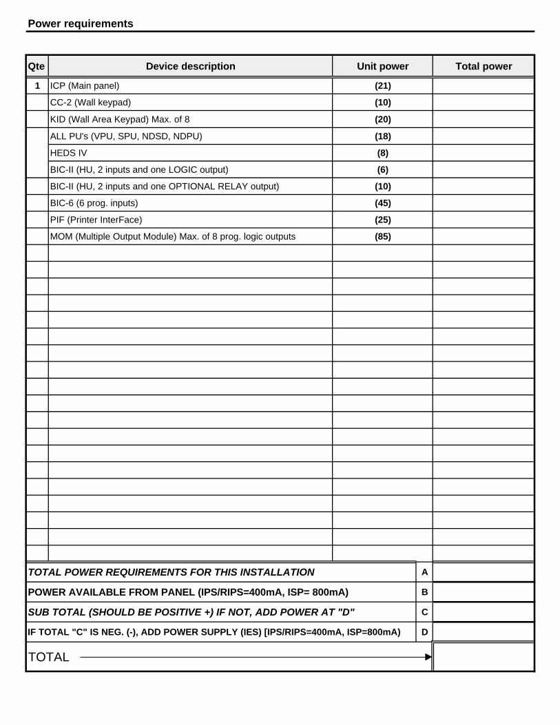
Power requirements
Qte Device description Unit power Total power
1 ICP (Main panel) (21)
CC-2 (Wall keypad) (10)
KID (Wall Area Keypad) Max. of 8 (20)
ALL PU's (VPU, SPU, NDSD, NDPU) (18)
HEDS IV (8)
BIC-II (HU, 2 inputs and one LOGIC output) (6)
BIC-II (HU, 2 inputs and one OPTIONAL RELAY output) (10)
BIC-6 (6 prog. inputs) (45)
PIF (Printer InterFace) (25)
MOM (Multiple Output Module) Max. of 8 prog. logic outputs (85)
TOTAL POWER REQUIREMENTS FOR THIS INSTALLATION A
POWER AVAILABLE FROM PANEL (IPS/RIPS=400mA, ISP= 800mA) B
SUB TOTAL (SHOULD BE POSITIVE +) IF NOT, ADD POWER AT "D" C
IF TOTAL "C" IS NEG. (-), ADD POWER SUPPLY (IES) [IPS/RIPS=400mA, ISP=800mA) D
TOTAL

INTELLIGUARD 9000
74-3046 38
Honeywell Europe S.A.3 Avenue du Bourget1140 BrusselsBelgium
Honeywell Asia Pacific Inc.Room 3213-3225Sun Hung kai CentreNo. 30 Harbour RoadWanchaiHong Kong
Home and Building ControlHoneywell Limited-Honeywell Limitée155 Gordon Baker RoadNorth York, OntarioM2H 3N7
Honeywell Latin American Region480 Sawgrass Corporate ParkwaySuite 200Sunrise FL 33325
Home and Building ControlHoneywell Inc.Honeywell PlazaP.O. Box 524Minneapolis MN 55408-0524
74-3046 D.A. 4-99
Printed in U.S.A. on recycled paper containing at least 10% post-consumer paper fibers. www.honeywell.com