73” aj laser 230z assembly instructions aircraft 73 inch...center line. the linkage hole in the...
TRANSCRIPT
73” AJ Laser 230z
Assembly Instructions

Rev 2.0 www.AJ-Aircraft.com/ Page 1
Congratulations
Whether you're looking to go out and go 3d huckin' or lay down a smooth-as-butter precision flight, the 73"
Laser 230z is for you! The wings have been thoroughly refined to allow precision flying, while not sacrificing
any 3d characteristics. With a generous fuselage height, the model flies as well on its side as it does upright.
Generously sized control surfaces give you excellent authority at all speeds. The Laser 230z features an
awesomely light but strong airframe and a light wing loading that will handle anything you want it to.
Building the airplane is very straight forward. The rudder cables are pre-installed, hinges are pre-installed and
blind nuts in the wing tips for the included SFG's make it easy to get this bird in the air in no time flat.
Transporting this big bird is no problem with the now included removable rudder. We've also added an
additional hard-point in the rudder for push-pull setups.
Can't decide which power system to add to your 73" Laser? The electric setup gives the ability to strap
batteries (8-12s) in and just go fly. You can expect around 6-7 minute flight times with great power and ultra-
reliability. Love the smell of burning gas in the morning? We've successfully tested the laser 230z with the
DA-35 and the Valley View 40cc twin. With a 16oz Fortitude tank you will see flight times approaching 15
minutes! When using the Valley View twin, it is recommended to add a second elevator servo for balance.
AJs' personal pick for this 73" Laser 230z is the 8s electric setup, ultra-floaty and a great flight envelope.
Whichever you choose, we're sure it'll put a smile on your face every time you fly it!
Up Your Game! Fly AJ
AJ Aircraft thanks you for the purchase of this airplane. Top grade materials and precision assembly has gone
into this to make this a top quality aircraft. Following the directions closely, will assure you many hours of
thrilling flight. Two years of design, development and testing has gone into this airframe. We hope you’re as
happy with it as we are!
Features
Specs:
Wing Span - 73"
Length - 70"
AUW - 10-11 lb
Power(Elec) - 2500+ Watt motor, 120Amp or 100Amp ESC, 8s 4400mah LiPo
Power(Gas) - 30-40cc
Radio - 5 channel with 4 high torque servos
What's in the box:
73” Laser 230 Airframe
Fiberglass Cowl & Wheel Pants
Carbon Fiber Main Gear
Pre-Hinged Control Surfaces
Removable Rudder
G-10 Control Horns
Dual Ball Links for all Connections
Carbon Fiber Wing Tube
Optional Side Force Generators (SFG)
Genuine Ultracote Covering
Wing Bags
Muffler Canister Mounts

Rev 2.0 www.AJ-Aircraft.com/ Page 2
WARNING!
AJ Aircraft’s extensive testing ensures a high quality kit that has gone through many stages to
provide you with a safe, reliable, airframe. Poor assembly will lead to an unsafe model and
therefore the instructions must be followed closely. Should you have any questions, please do
not hesitate to contact us. The safe operation of this model is your responsibility and yours
alone. If you are a beginner or have never flown a model of this size and power you should
attempt it with the help of an experienced pilot. This product should not be considered a toy,
but rather a sophisticated, working model that functions much like a full-scale airplane.
Because of its performance capabilities, this product, if not assembled and operated correctly,
could cause injury to you or spectators and damage to property.

Rev 2.0 www.AJ-Aircraft.com/ Page 3
Contents
Congratulations ....................................................................................................................................................................... 1
Features .................................................................................................................................................................................. 1
Optional Configurations .......................................................................................................................................................... 4
Recommended Items for Completion ..................................................................................................................................... 4
Tools ........................................................................................................................................................................................ 5
Covering .................................................................................................................................................................................. 6
Wings ...................................................................................................................................................................................... 6
Landing Gear ......................................................................................................................................................................... 11
Wheel Pants .......................................................................................................................................................................... 12
Fuselage ................................................................................................................................................................................ 14
Elevator ................................................................................................................................................................................. 16
Rudder ................................................................................................................................................................................... 21
Push-Pull Rudder Control .................................................................................................................................................. 21
Pull-Pull Rudder Control .................................................................................................................................................... 22
Electric Motor ....................................................................................................................................................................... 25
Gas Engine ............................................................................................................................................................................. 27
Cowl & Canopy ...................................................................................................................................................................... 30
Radio Installation & Setup .................................................................................................................................................... 32
Before starting, read through the entire set of instructions to familiarize yourself with the
process.
If there’s ever a question, contact AJ Aircraft.
Inspect the packing material carefully for the rudder hinge pin.

Rev 2.0 www.AJ-Aircraft.com/ Page 4
Optional Configurations
This model is designed for a gasoline engine or an electric motor. Fastener, servo hardware, and electric motor box are
provided for optional setups. You also have the option of using 1 or 2 elevator servos and a pull-pull rudder servo or 1
elevator servo and a push-pull rudder servo setup.
Recommended Items for Completion
Power System
o Electric Motor (If you choose to go electric.)
Hacker A60-5S or Equivalent
Castle Ice 100 Amp or Equivalent
12” ESC (Servo) Wire Extensions
8s Battery
Prop suited for the motor you choose. (21x10, …)
3” (76mm) Spinner
o Gas Engine (If you choose to go gasoline.)
DA-35 or Equivalent 35cc
Standard sized metal geared throttle servo.
Ignition Shut Off
Ignition/Receiver Battery
16 oz Gasoline Safe Fuel Tank
Gasoline Safe Fuel Line
Fuel Dot
Fuel Filter
2x 12” Servo Wire Extensions
Prop suited for the engine you choose. (20x8, 20x9…)
3” (76mm) Spinner
Aileron Servos
o 2x 250 oz/in Metal Geared, (Hitec HS-7955TG Recommended)
o 2x 12” Servo Wire Extensions (in wings)
o 2x 6” Servo Wire Extensions (to receiver)
o 2x 1.25” Servo Arm for 3D Aerobatics (Or a heavy duty servo arms for sport flying.)
AJ flies this airframe with the following equipment:
Hacker A60-5s
Falcon 21x10 prop
Jetti Mezon 120 or
Castle Ice 100 ESC
2x Thunder Power 4s 4400mah
G8 Performance Pro 45C
Castle Pro BEC
Thunder Power 2s 2100mah G8
Pro-lite + 25C
Futaba 9157 servos on
Elevator/Rudder
Futaba 9452 servos on Ailerons

Rev 2.0 www.AJ-Aircraft.com/ Page 5
Rudder Servo
o This model can be configured with a pull-pull cable rudder servo or using a push-pull servo mounted in the
tail.
o 1x 250 oz/in Metal Geared, (Hitec HS-7955TG Recommended)
2.5” Double Servo Arm for a Pull-Pull cable setup.
1.5” Servo Arm for a Push-Pull setup. (Or a heavy duty servo arms for sport flying.)
24” Servo Wire Extension for a Push-Pull setup.
Elevator Servo
o This model can be configured with 1 or 2 elevator servos.
(You must use a pull-pull rudder setup if you plan to use 2 elevator servos.)
o 250 oz/in Metal Geared, (Hitec HS-7955TG Recommended)
o 1.5” Servo Arm for 3D Aerobatics (Or a heavy duty servo arms for sport flying.)
o 24” servo wire extensions (1 or 2)
Radio System
o 5 or 6 channel full range radio system
o Power Switch
o Receiver Battery
o Vibration padding for receiver and receiver battery.
Tools
Blue Painters Masking Tape Thin CA Glue 30 Minute Epoxy Polyurethane Glue (Gorilla Glue) Denatured Alcohol Paper Towels Removable Thread Locker (Loctite 242, Blue) Metric & SAE (fractional) Allen Wrenches Hobby Knife & Fresh Blades Covering Iron (Trim Iron)
Small Flat File Small Round File Electric Drill w/ Assorted Small Bits Small Flat Blade Screwdrivers Small Phillips Screwdriver Sandpaper (150-220 Grit) Needle Nose Pliers Crimping Plyers Measuring Tape & Ruler

Rev 2.0 www.AJ-Aircraft.com/ Page 6
Covering
The covering on your Laser may have developed loose areas through temperature and humidity changes between
manufacturing and shipping. This may also occur during the summer heat. The covering may require retightening a few
times during your first summer of flying.
Take a few minutes to go over all of the seams making sure all edges are secure. Then proceed to shrinking any area
that may need tightening. (Using an iron sock will reduce scratches.)
Wings
The ailerons are pre hinged and glued to the wing. Firmly
tug at each hinge point to ensure hinges are installed
properly. It’s better to find a loose hinge now rather than
during a flight.
Carefully locate the aileron servo pocket. (Shining a light through opposite side of the wing will help highlight the pocket location.) Use a new hobby knife blade to cut though the covering. Cut from the corners of the pocket towards the center of the pocket so the covering can be folded in.
Gently snap off the servo wire installation string and temporarily secure it out of the way. Do not pull it out of the wing. Use a trim iron to seal the bottom surface of the wing around the servo pocket. Fold the cut covering under the wing sheeting and attach it to the inside edge of the pocket.
At 200-220°F (93-104°C) the adhesive on UltraCote® becomes active
allowing the covering to be attached to the model. While 220° will fully
bond the covering to the model it is well below the temperature that
causes UltraCote® to shrink.
At 300°F (149°C) the initial shrinking of UltraCote® begins.
At 350°F (176°C) UltraCote® reaches its maximum shrinking point. Raising
the temperature above this point will not cause further shrinkage.
Use as little heat as needed. Using too much heat may cause reshrinking
issues later.
Pro Tip - If the iron you're using does not display the actual temperature,
here is a tip that will ensure your iron is properly set.Water boils at 212°F.
Allow your iron to warm up at a medium setting. When the iron reaches its
stabilized temperature, carefully pour a few drops of water on the iron's
surface. Adjust the temperature until the water just begins to boil off. This
method is surprisingly accurate and is generally within 10° (of the exact
application temperature of 220).

Rev 2.0 www.AJ-Aircraft.com/ Page 7
Carefully locate the aileron control horn slots. Use a covering sealing iron to bond the covering in the area the control horn will sit. Trim the covering away to expose the slots. Be careful you don’t cut through to the top side covering.
Use the control horns from the “Wings” part bag.
Test fit the control horn halves in the slot first individually, then as an assembly. The fit should be snug.
Check the alignment of the control horn to the hinge center line. The linkage hole in the control horn should be aligned with the hinge centerline.
With the control horn in position apply painter’s masking tape around the control horn base. Put the tape up to the base edge. Not under or over it.
Assemble a rod end to the control horn using a supplied machine screw and nylon lock nut. Assembling the ball link to the control horn at this step will help keep the control horn halves parallel during installation later.

Rev 2.0 www.AJ-Aircraft.com/ Page 8
Remove the control horn leaving the tape in position. Using a new hobby knife blade and lightly cut through the covering but not into the balsa sheeting. Cut inside the tape edge about 1/16”.
Use sand paper to roughen the lower portion of the control horns on both sides. Roughen one side of the base plate. This will help the epoxy bond to the control horn parts.
Apply epoxy to the slots in the aileron. Use a pin to help push some epoxy in.
Apply epoxy to the control horn assembly and insert it into the aileron slots.
Wipe away excess epoxy using a paper towel soaked with denatured alcohol. Use an upward rolling motion as you wipe the excess epoxy to lift it from the surface. This helps reduce smearing the epoxy.
Check the alignment along the hinge line as you did when you test fit the control horn. Reposition as needed.
Allow the epoxy to partially cure. Peel away the masking
tape after the epoxy is securely holding the control horn
in place and still soft enough to easily remove the tape.
Set the wing aside and let the epoxy fully cure.

Rev 2.0 www.AJ-Aircraft.com/ Page 9
Connect the servo to a receiver and power supply. Turn
on you transmitter. Set trim and sub trim to zero. Install
a servo arm on the servo approximately perpendicular to
the servo side. Use the transmitter’s sub trim to make it
perpendicular.
Attach the servo wire to the installation string and gently
pull the wire through the wing as you insert the servo
into the wing. (Depending on the length of the servo wire
provided it may be necessary to install a servo extension
wire before installing through the wing.)
Secure wire extensions to servo leads using shrink wrap
or a safety clip.
Pre-drill for the servo mounting screws using a 1/16” drill bit. Install the servo with the wood screws that came with your servos. Remove the screws and servo. Apply a drop of thin CA glue into each mounting screw hole. This will harden the wood around the screws and provide a more secure installation. (Allow the CA glue to dry before reinstalling the servo.)
Reinstall the servo. Assemble a connecting rod and ball link and to aileron ball link. Check the length of the assembly to the servo arm with the aileron edge aligned with the wing. Once the correct length of the assembly is found connect it to the servo arm using the provided machine screws washer and lock nut. (Turn on the transmitter, receiver and servo while making adjusting to the connecting rod. This will keep the servo in its correct position.)

Rev 2.0 www.AJ-Aircraft.com/ Page 10
Remove the side force generators and spacer plates from
the wing bag. Carefully locate the 2 mounting holes in
each part and trim away the covering.
The wing tips have a blind nut installed beneath the
covering. Use a hobby knife to trim away the covering.
(Use the holes in a spacer plate to help locate the holes in
the wing tip.) Assemble the spacer plate and the side
force generator to the wing with the supplied screws and
washers.

Rev 2.0 www.AJ-Aircraft.com/ Page 11
Landing Gear
Use the landing gear fasteners located on the bottom of
the fuselage along with 3 flat washers located in the
landing gear package to assemble the landing gear. Add a
drop of removable thread locker to the screws during
assembly.
Place the wood filler block over the landing gear. Pay
attention to the fit as it is directional. We suggest using a
piece of white covering or clear packing tape to hold the
filler block in position.
Install the landing gear cuffs with the holes towards the
bottom of the airplane. Use a flat blade screw driver with
a gentle twist to help slide the cuff over the landing gear.
Secure the cuffs using 4 Phillips head screws from the
landing gear hardware package.
You may also choose to use a silicon adhesive (RTV) to
secure the cuffs in position. Apply a bead of adhesive just
above the mounting holes and slide the cuff over the
adhesive.

Rev 2.0 www.AJ-Aircraft.com/ Page 12
Ensure all set screws are tight on the pre-assembled tail
wheel assembly.
Use the landing gear fasteners locate on the bottom of
the fuselage along with 2 flat washers located in the
landing gear package to mount the carbon fiber landing
gear. Add a drop to removable thread locker to screws
during assembly.
Wheel Pants
(You might want to install the wheels and wheel pants
last when assembling you airplane. They may get in the
way while handling during other assembly steps.)
There are 6 blind nuts provided and 6 blind nuts used in
this kit. Notice that there are 2 different sizes! Take the
time to match up blind nuts to machine screws before
proceeding to ensure you do not get them mixed up.
Two blind nuts will be used on the canopy and 4 blind
nuts will be used on the wheel pants.
File a flat on the wheel axel for the wheel collar set screw.
(Making it perpendicular to the wrench flats may help
during installation and tightening later.)
Temporarily clamp the wheel pants in position.

Rev 2.0 www.AJ-Aircraft.com/ Page 13
Drill through the holes in the landing gear and through to
the inside of the wheel pant.
Use a machine screw and washer to draw a blind nut into
the wheel pant.
Slide the wheel onto the axel. Add the wheel collar and
tighten the set screw. Ensure it rotates freely.
Put the wheel and axel into the wheel pant then put the
axel threads through the landing gear.
Get the wheel pant mounting screws started but don’t
fully tighten.
Add the nylon locknut to the axel and tighten. Make sure
you can still get to the wheel collar set screw.
Finish by tightening the wheel pant mounting screws.

Rev 2.0 www.AJ-Aircraft.com/ Page 14
Fuselage
Inspect for any interior joints that may have loosened as
a result of shipping & handling. Apply thin CA glue as
needed. Apply thin CA glue around the joints of the
fuselage core and rudder servo tray.
Carefully locate the mounting holes for the wing and trim
away the covering. There will be 2 holes for wing
alignment pins, 1 hole for the wing bolt, and a slot to pass
the servo wire through. Shine a flashlight through the
fuselage to highlight the holes if you have trouble
locating them.
Carefully locate the horizontal stabilizer pocket. Use a
trim iron to seal the covering around the edges of the
pocket before trimming. Use a new hobby knife blade to
cut though the covering.
Rev 2.0 www.AJ-Aircraft.com/ Page 15
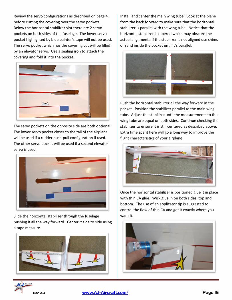
Review the servo configurations as described on page 4
before cutting the covering over the servo pockets.
Below the horizontal stabilizer slot there are 2 servo
pockets on both sides of the fuselage. The lower servo
pocket highlighted by blue painter’s tape will not be used.
The servo pocket which has the covering cut will be filled
by an elevator servo. Use a sealing iron to attach the
covering and fold it into the pocket.
The servo pockets on the opposite side are both optional.
The lower servo pocket closer to the tail of the airplane
will be used if a rudder push-pull configuration if used.
The other servo pocket will be used if a second elevator
servo is used.
Slide the horizontal stabilizer through the fuselage
pushing it all the way forward. Center it side to side using
a tape measure.
Install and center the main wing tube. Look at the plane
from the back forward to make sure that the horizontal
stabilizer is parallel with the wing tube. Notice that the
horizontal stabilizer is tapered which may obscure the
actual alignment. If the stabilizer is not aligned use shims
or sand inside the pocket until it’s parallel.
Push the horizontal stabilizer all the way forward in the
pocket. Position the stabilizer parallel to the main wing
tube. Adjust the stabilizer until the measurements to the
wing tube are equal on both sides. Continue checking the
stabilizer to ensure it is still centered as described above.
Extra time spent here will go a long way to improve the
flight characteristics of your airplane.
Once the horizontal stabilizer is positioned glue it in place
with thin CA glue. Wick glue in on both sides, top and
bottom. The use of an applicator tip is suggested to
control the flow of thin CA and get it exactly where you
want it.

Rev 2.0 www.AJ-Aircraft.com/ Page 16
Elevator
The hardware provided may be used to control elevator
halves with 1 or 2 servos. Or the hardware can be used
with 1 elevator servo and 1 rudder servo in a push-pull
configuration.
Before you cut any covering on the elevator make sure
you have the correct half. If you cut open the servo
pocket in the left of the fuselage make sure you are
working with the left elevator.
Install the elevator control horn using the same process
as you did when assembling the ailerons.
Use a covering sealing iron to bond the covering in the
area the control horn will sit. Trim the covering away to
expose the slots.
Test fit the control horn halves in the slot individually,
then as an assembly. The fit should be snug.
Check the alignment of the control horn to the hinge
center line as you did with the wing. The linkage hole in
the control horn should be aligned with the hinge
centerline.
With the control horn in position apply painter’s masking
tape around the control horn base. Put the tape up to
the base edge. Not under or over it.
Assemble a rod end to the control horn using a supplied
machine screw and nylon lock nut. (Assembling the ball
link to the control horn at this step will help keep the
control horn halves parallel during installation.)

Rev 2.0 www.AJ-Aircraft.com/ Page 17
Remove the control horn leaving the tape in position.
Using a new hobby knife blade lightly cut through the
covering but not into the balsa sheeting. Cut inside the
tape edge about 1/16”.
Use sand paper to roughen the lower portion of the
control horns on both sides. Roughen one side of the
base plate. This will help the epoxy bond to the control
horn parts.
Apply epoxy to the slots in the elevator. Use a pin to help
push some epoxy into the slots.
Apply epoxy to the control horn assembly and insert it
into the elevator slots.
Wipe away excess epoxy using a paper towel soaked with denatured alcohol. Use an upward rolling motion as you wipe the excess epoxy to lift it from the surface. This helps reduce smearing the epoxy.
Check the alignment along the hinge line as you did when
you test fit the control horn. Reposition as needed. Allow
the epoxy to partially cure. Peel away the masking tape
after the epoxy is securely holding the control horn in
place and still soft enough to easily remove the tape. Set
aside and let the epoxy fully cure. (Repeat on second
elevator half if you will be using 2 elevator servos.)
Roughen up the jointer plate for the elevator halves with a piece of sand paper so the epoxy will adhere better. (The joiner plate is not used if you plan to use 2 elevator servos. Steps related to the jointer plate can be skipped)
Test fit the elevator joiner plate to each elevator half. Insert the joiner plate into both halves and look down the hinge line. It should be straight. If not use a small file and adjust the slots a little at a time. (Do not glue it yet.)

Rev 2.0 www.AJ-Aircraft.com/ Page 18
Insert hinge pins into the elevator halves and the horizontal stabilizer. Check the fit and gap at the hinge line. You may need to adjust the hinge holes to minimize the gap.
A small round file can be used to give the hinges some clearance. Cleaning out the holes will also help you close up any gap. Turn a 1/8” drill into the holes by hand.
Test fit pieces together and make adjustments so you get a good fit between the elevator and the stabilizer. Check the hinge gap and the gap at the counter balance. Make sure there is clearance between the elevator joiner plate and the fuselage. Hold half of the elevator aligned to the leading edge of the stabilizer and ensure the opposite elevator half is also aligned. Sand or shim the elevator joiner plate until both halves are aligned to at the leading edge of the stabilizer.
Practice assembling the elevator, hinges and jointer plate together without glue so things go smoothly when you glue it all together.
Apply petroleum jelly (Vaseline) to the center hinge pin portion of each hinge. This will help prevent glue from getting into the hinge when gluing then into the elevator. Avoid getting petroleum jelly on the barbed portion of the pin. If you do clean it off with alcohol.
Use painter masking tape to prevent glue from getting where you don’t want it.
Rev 2.0 www.AJ-Aircraft.com/ Page 19
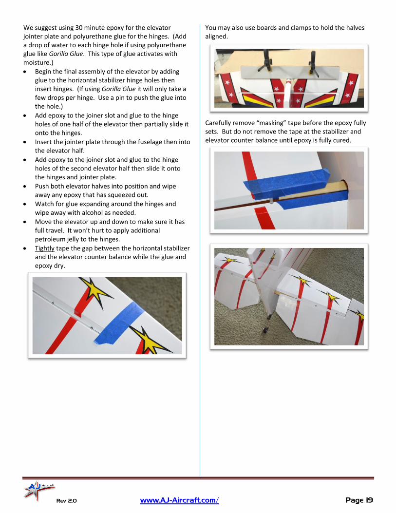
We suggest using 30 minute epoxy for the elevator jointer plate and polyurethane glue for the hinges. (Add a drop of water to each hinge hole if using polyurethane glue like Gorilla Glue. This type of glue activates with moisture.)
Begin the final assembly of the elevator by adding glue to the horizontal stabilizer hinge holes then insert hinges. (If using Gorilla Glue it will only take a few drops per hinge. Use a pin to push the glue into the hole.)
Add epoxy to the joiner slot and glue to the hinge holes of one half of the elevator then partially slide it onto the hinges.
Insert the jointer plate through the fuselage then into the elevator half.
Add epoxy to the joiner slot and glue to the hinge holes of the second elevator half then slide it onto the hinges and jointer plate.
Push both elevator halves into position and wipe away any epoxy that has squeezed out.
Watch for glue expanding around the hinges and wipe away with alcohol as needed.
Move the elevator up and down to make sure it has full travel. It won’t hurt to apply additional petroleum jelly to the hinges.
Tightly tape the gap between the horizontal stabilizer and the elevator counter balance while the glue and epoxy dry.
You may also use boards and clamps to hold the halves aligned.
Carefully remove “masking” tape before the epoxy fully sets. But do not remove the tape at the stabilizer and elevator counter balance until epoxy is fully cured.
Rev 2.0 www.AJ-Aircraft.com/ Page 20
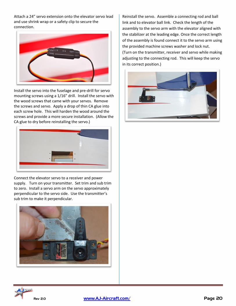
Attach a 24” servo extension onto the elevator servo lead and use shrink wrap or a safety clip to secure the connection.
Install the servo into the fuselage and pre-drill for servo mounting screws using a 1/16” drill. Install the servo with the wood screws that came with your servos. Remove the screws and servo. Apply a drop of thin CA glue into each screw hole. This will harden the wood around the screws and provide a more secure installation. (Allow the CA glue to dry before reinstalling the servo.)
Connect the elevator servo to a receiver and power supply. Turn on your transmitter. Set trim and sub trim to zero. Install a servo arm on the servo approximately perpendicular to the servo side. Use the transmitter’s sub trim to make it perpendicular.
Reinstall the servo. Assemble a connecting rod and ball
link and to elevator ball link. Check the length of the
assembly to the servo arm with the elevator aligned with
the stabilizer at the leading edge. Once the correct length
of the assembly is found connect it to the servo arm using
the provided machine screws washer and lock nut.
(Turn on the transmitter, receiver and servo while making
adjusting to the connecting rod. This will keep the servo
in its correct position.)

Rev 2.0 www.AJ-Aircraft.com/ Page 21
Rudder
The rudder control can be configured as a push-pull
system or as a pull-pull cable system. See the
configuration options listed on page 4.
Inspect the packing material carefully for the rudder
hinge pin. It is typically taped to the inside of the box.
Push-Pull Rudder Control
A push-pull system will use the hardware provided in the
elevator parts bag.
Notice that the control horns for the push-pull system
shown at the top of this picture are longer then the pull-
pull control horns.
The rudder is built with control horn slots for the push-
pull control system and the pull-pull control system. The
blue painter’s tape indicates the control horn locations.
The push-pull control horn slots are located near the
bottom of the rudder.
The picture below shows a mockup of the rudder push-
pull system. The installation process of the servo and
control horn is the same as the ailerons and the elevator.
The pull-pull cables can be removed and the covering will
need to be patched with covering or a smartly placed
decal.

Rev 2.0 www.AJ-Aircraft.com/ Page 22
Pull-Pull Rudder Control
A pull-pull system will use the hardware provided in the
rudder parts bag.
The rudder is built with control horn slots for the push-
pull control system and the pull-pull control system. The
blue painter’s tapes indicate the control horn locations.
The pull-pull control horn slots are located higher up on
the rudder.
Cut the rudder covering to expose the control horn slots
on both sides of the rudder as you did for the ailerons
and elevator. Test fit the control horns, mask off the area
surrounding the control horns and use a fresh knife blade
and cut the covering as you did with the ailerons and
elevator.
Use sand paper to roughen up the control horns so the
epoxy will adhere better. Assembly the control horns
with a ball link and brass cable eye. Thread the cable
eyes about half way into the ball link.
Tests fit the control horns to the slots and align with the
hinge line. The control horns should be symmetrical
about the hinge line.
Use 30 minute epoxy to glue the control horns in place.
Check the alignment, peal the masking tape away and set
aside for the epoxy to cure.

Rev 2.0 www.AJ-Aircraft.com/ Page 23
Slide the tail wheel guide through the ball link eye which
is pre-installed at
the bottom of the
rudder. Align the
rudder hinges to the
vertical stabilizer
hinges. Insert the
rudder hinge pin
through the top of
the rudder then
through each of the
hinges. You may
need to trim the
length of the hinge
pin if it interferes
with the tail wheel
assembly.
Install the rudder servo into the fuselage and pre-drill for servo mounting screws using a 1/16” drill. Install the servo with the wood screws that came with your servos. Remove the screws and servo and apply a drop of thin CA glue into each mounting screw hole. This will harden the wood around the screws and provide a more secure installation. (Allow the CA glue to dry before reinstalling the servo.)
Connect the rudder servo to a receiver and power supply. Turn on you transmitter. Set trim and sub trim to zero. Install a servo arm on the servo approximately perpendicular to the servo side. Use the transmitter’s sub trim to make it perpendicular to the side of the servo.
Tread the brass cable eyes about half way into the ball
links.
Start the cable assembly at the servo end inside the
fuselage. Thread on 2 crush sleeves and the brass cable
eye. (If wish to add shrink wrap over the connection,
thread it on first.)
Loop around the cable eye and go back through a crush
sleeve.
Loop around and back through the crush sleeve again.

Rev 2.0 www.AJ-Aircraft.com/ Page 24
Adjust the loops and crimp the sleeve with crimping
plyers or the non-serrated surface of standard plyers.
Slide the tail through the second crush sleeve and crimp.
Pull the slack out of the cables and make sure the cables
cross once inside the fuselage. Connect the ball links to
the rudder control horn.
Tape the rudder in position aligned to the vertical
stabilizer. With the servo powered up and centered
repeat the crimping process on the rudder end of the
cable. Before you crimp the crush sleeves make sure the
cable is not looped around the cable eye at the servo end.
Pull the cable snug. You don’t need to make the cable a
guitar string tight.
Remove the tape and adjust the cable lengths to center
the rudder by turning the cable eyes into the ball links.

Rev 2.0 www.AJ-Aircraft.com/ Page 25
Electric Motor
The firewall is marked with the centerline offset to
account for the built in thrust angle.
Use the DLE30 templet to locate the mounting holes for
the electrical motor mounting box. This template uses a
54mm X 70mm hole pattern which matches the motor
box.
Drill 3/16” (4.5mm) holes through the firewall. Then use
a 4mm bolt and washer to draw blind nuts into the back
of the firewall.
Use 4mm bolts and washers to secure the motor box to
the fire wall. Apply removable thread locker to the bolts
during assembly.
Install nylon lock nuts to the back of the firewall to
prevent bolts from backing out.
Use an “X” mount with a mounting bolt circle of 75mm to
mount your motor. Use the supplied 4mm bolts and
washers. Add removable thread locker during installation.

Rev 2.0 www.AJ-Aircraft.com/ Page 26
The motor’s backer plate should be about 3.37” (85mm)
from the motor mounting box. This will provide .12”
(3mm) clearance between the cowl and the motor backer
plate.
The prop backer plate will be about 6.3” (160mm) from
the fuselage firewall.
The firewall has a built in thrust angle which centers the
prop shaft in the center of the cowl.
Use nylon zip ties to secure the ESC to the bottom or side
of the motor box. We recommend putting a small piece
of foam between the ESC and motor box to dampen
vibrations.
Place hook and loop tape to the battery tray and your
battery. Loop hook and loop straps around the battery.
We recommend using at least a 1” strap if you intend to
do high G, 3D maneuvers.
Use the balsa sheet and 2mm wood screws provided to
cover the exhaust tunnel. Leaving this open may trap air
and result in unwanted flight characteristics.

Rev 2.0 www.AJ-Aircraft.com/ Page 27
Gas Engine
The firewall is marked with the centerline offset to
account for the built in thrust angle. This will position the
prop in the center of the cowl.
Use these centerlines to position the mounting holes for
the engine you decide to use. (You can use the DLE30
template if your engine uses a 54mm X 70mm hole
pattern. Some engine manufactures provide templates
to help locate the mounting holes, fuel line and throttle
linkage. Before using these templates measure them
after printing to make sure they have printed to scale.)
Drill the mounting holes then temporarily mount your
engine standoff and the engine. (A DLE35RA is shown.)
Bolt the engine standoff to the firewall from the back.
The distance between the prop backer plate and the
firewall should be 6.3” (160mm). This will provide space
between the spinner and the cowl.
Check for clearance between the firewall and the
carburetor. This distance should be noted in your
engine’s manual. If you don’t have at least the
recommended space cut an opening in the firewall so the
carburetor can get air.
Mark the locations for the throttle linkage and fuel line to
pass through the firewall. (It may be possible to rotate
the throttle arm on the carburetor which will give you
options for servo placement.) Plan the placement of the
throttle servo then drill through the firewall as needed.
Rev 2.0 www.AJ-Aircraft.com/ Page 28
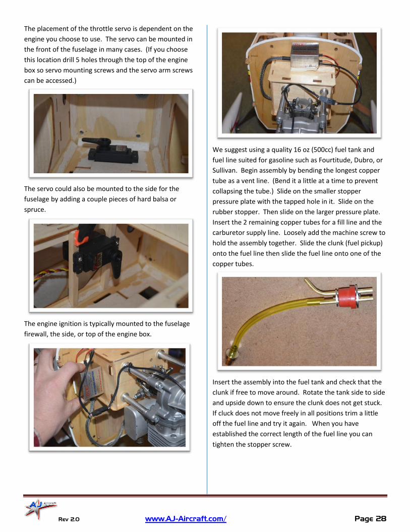
The placement of the throttle servo is dependent on the
engine you choose to use. The servo can be mounted in
the front of the fuselage in many cases. (If you choose
this location drill 5 holes through the top of the engine
box so servo mounting screws and the servo arm screws
can be accessed.)
The servo could also be mounted to the side for the
fuselage by adding a couple pieces of hard balsa or
spruce.
The engine ignition is typically mounted to the fuselage
firewall, the side, or top of the engine box.
We suggest using a quality 16 oz (500cc) fuel tank and
fuel line suited for gasoline such as Fourtitude, Dubro, or
Sullivan. Begin assembly by bending the longest copper
tube as a vent line. (Bend it a little at a time to prevent
collapsing the tube.) Slide on the smaller stopper
pressure plate with the tapped hole in it. Slide on the
rubber stopper. Then slide on the larger pressure plate.
Insert the 2 remaining copper tubes for a fill line and the
carburetor supply line. Loosely add the machine screw to
hold the assembly together. Slide the clunk (fuel pickup)
onto the fuel line then slide the fuel line onto one of the
copper tubes.
Insert the assembly into the fuel tank and check that the
clunk if free to move around. Rotate the tank side to side
and upside down to ensure the clunk does not get stuck.
If cluck does not move freely in all positions trim a little
off the fuel line and try it again. When you have
established the correct length of the fuel line you can
tighten the stopper screw.

Rev 2.0 www.AJ-Aircraft.com/ Page 29
The fuel tank vent line should loop up over the tank then
exit through the bottom of the airplane. The fill line
should be capped by a fuel dot. The carburetor supply
line should run to a fuel line filter then through the
firewall to the carburetor.
Position the fuel tank in front of the wing tube. Placing a
piece of foam under the tank will prevent fuel foaming
from vibration. Secure the tank using the hook and loop
straps running through the slots on the plywood tray. We
recommend using at least a 1” strap if you intend to do
high G, 3D maneuvers.
Use the balsa sheet and 2mm screws to cover the exhaust
tunnel if you do use canister style exhaust. The tunnel
can be left open and the fuselage bottom venting can be
installed to allow for additional engine cooling airflow.
If you plan on using canister style exhaust leave the
exhaust tunnel open. Install the provided pipe mounts in
the tunnel and fuselage venting.
Cut the cowl as needed to clear the engine head, spark
plug and muffler. Cut a large opening at the rear of the
cowl to keep your engine running cool.

Rev 2.0 www.AJ-Aircraft.com/ Page 30
Cowl & Canopy
Use painters tape to transfer the mounting locations to
the cowl. Apply painters tape over the mounting taps.
Push a pin through the tape and hole in the mounting
tab.
Peal back the tape to uncover the mounting tabs and
install the cowl. Tape the cowl into position. Use a pin to
drill holes in the cowl through the locating holes you
created in the tape. Rotate the pin as you push it through
the cowl. (You can also use a pen to mark the hole
locations on the cowl.)
Remove the cowl and use a 3/32” drill to open up the pin
holes. (Or drill at the marked locations.)
Use 3mm wood screws to mount the cowl.
Apply thin CA glue to the mounting tabs and screw holes.
(Allow plenty of time for the CA glue to dry before
reinstalling the cowl.)
There are 6 blind nuts provided and 6 blind nuts used in
this kit. Notice that there are 2 different sizes! Take the
time to match up blind nuts to machine s before
proceeding to ensure you do not get them mixed up.
Two blind nuts will be used on the canopy and 4 blind
nuts will be used on the wheel pants.
Rev 2.0 www.AJ-Aircraft.com/ Page 31
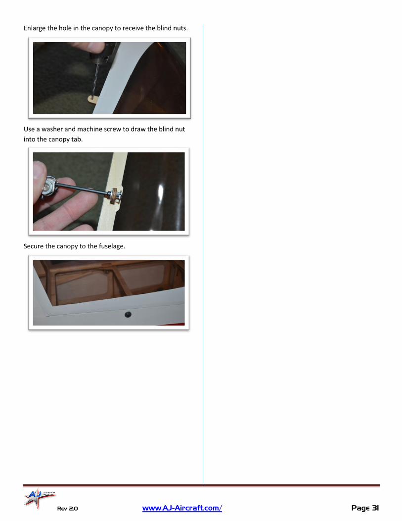
Enlarge the hole in the canopy to receive the blind nuts.
Use a washer and machine screw to draw the blind nut
into the canopy tab.
Secure the canopy to the fuselage.
Rev 2.0 www.AJ-Aircraft.com/ Page 32
Radio Installation & Setup
Take the time to properly balance and trim your aircraft.
Use the suggested throws below as your starting point
then fine tune to your flying preferences after your first
few flights.
Your receiver can be mounted anywhere in the airframe.
Behind the wing tube works well on this fuselage. A piece
of foam rubber should be used between the fuselage and
the receiver to dampen any vibration.
The CG is measured back from the leading edge of wing
5.0 - 5.6” (127-143mm).
You can adjust your CG depending on your flying style.
If you fly aggressive 3D aerobatics you’ll want to find a
more of a neutral CG. When its flown level inverted it
requires little to no elevator input to maintain altitude.
If you enjoy sport & precision aerobatics you’ll want a
slightly nose heavy CG.
To test the CG fly left or right at about 3/4 to full throttle
and pull to a 45 degree up-line. Roll inverted and let go
of the elevator stick. A correct nose heavy CG will slowly
arc to the level. A neutral CG should nearly hold the up-
line. And a tail heavy CG will steepen the up-line.
While the final setup is of personal preference, these are
some general guidelines to make your first flight a
success.
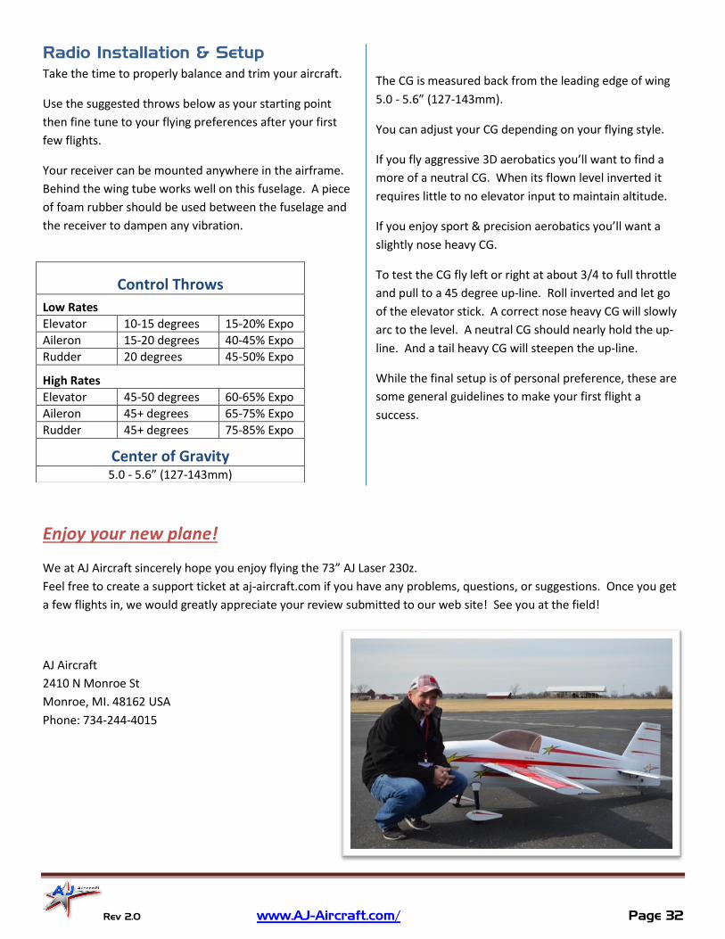
Enjoy your new plane!
We at AJ Aircraft sincerely hope you enjoy flying the 73” AJ Laser 230z.
Feel free to create a support ticket at aj-aircraft.com if you have any problems, questions, or suggestions. Once you get
a few flights in, we would greatly appreciate your review submitted to our web site! See you at the field!
AJ Aircraft
2410 N Monroe St
Monroe, MI. 48162 USA
Phone: 734-244-4015
Control Throws
Low Rates
Elevator 10-15 degrees 15-20% Expo
Aileron 15-20 degrees 40-45% Expo
Rudder 20 degrees 45-50% Expo
High Rates
Elevator 45-50 degrees 60-65% Expo
Aileron 45+ degrees 65-75% Expo
Rudder 45+ degrees 75-85% Expo
Center of Gravity
5.0 - 5.6” (127-143mm)