71612c 12.5 gb/s error performance analyzer
TRANSCRIPT
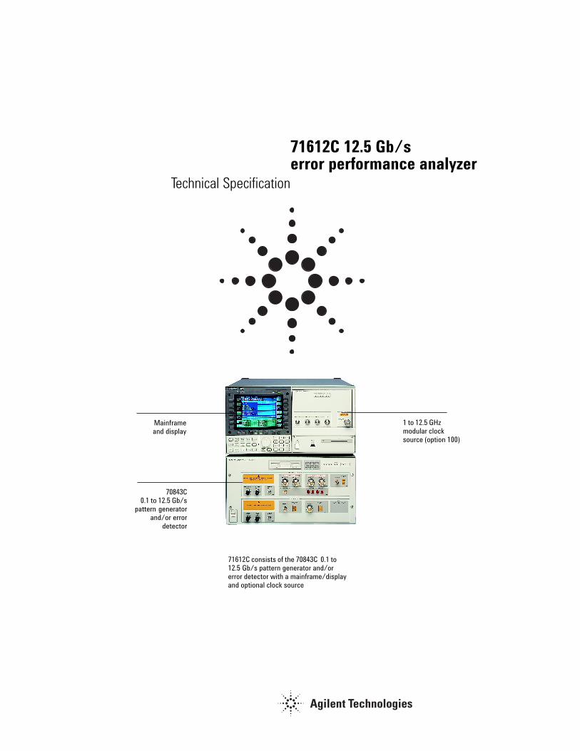
71612C 12.5 Gb/serror performance analyzer
Technical Specification
Mainframeand display
70843C0.1 to 12.5 Gb/s
pattern generatorand/or error
detector
1 to 12.5 GHzmodular clocksource (option 100)
71612C consists of the 70843C 0.1 to12.5 Gb/s pattern generator and/orerror detector with a mainframe/displayand optional clock source

2
71612C error performance analyzer (1 to 12.5 Gb/s)
Contents
Introduction .................................................................................................... 2General ............................................................................................................ 3Test Patterns .................................................................................................. 4Pattern Generator .......................................................................................... 5Error Detector ................................................................................................ 9
1. Introduction
The Agilent 71612C Error Performance Analyzer is the ideal solution for theresearch, development and manufacturing test of Gbit lightwave and digitalcomponents, devices and subsystems from 100Mb/s to 12.5Gb/s.
With this high performance serial pattern generator and error detector, you canperform error analysis to verify the operation and quality of lightwave submarinecable systems, SONET/SDH telecom and datacom transceivers, Gbit datacomserial links, high-speed logic devices, and optical amplifiers and modulators.
The analyzer can be used to test 10.6 Gbit ethernet and forward error correction(FEC) rates giving you a breadth of applications to help you thoroughly test andcharacterize your devices for complete confidence in your product.

3
2. General
All specifications are valid after a 30-minute warm-up period.
Temperature range for specified operation:
100 MHz to 10 GHz, 5 to 40ºC.10GHz to 12.3GHz, 5ºC to 35ºC12.3GHz to 12.5GHz, 20ºC to 30ºC
Calibration Interval 2 years (recommended)

4
3. Test patterns
Prbs 231 – 1 Polynomial D31 + D28 + 1 = 0 (inverted)223 – 1 Polynomial D23 + D18 + 1 = 0 (inverted)(ITU-T O.151)215 – 1 Polynomial D15 + D14 + 1 = 0 (inverted)(ITU-T O.151)210 – 1 Polynomial D10 + D7 + 1 = 0 (inverted)27 – 1 Polynomial D7 + D6 + 1 = 0 (inverted)
Zero Substitution and variable mark density
Test Patterns: 8192 bits based on 213-1 PRBS2048 bits based on 211-1 PRBS1024 bits based on 210-1 PRBS128 bits based on 27-1 PRBS
Zero Substitution Zeros can be substituted for data to extend the longest run of zeros in theabove patterns. The longest run can be extended to the pattern length-1. The bit following the substituted zeros is set to 1.
Variable Mark Density The ratio of ones to total bits in the abovepatterns can be set to 1/8, 1/4, 1/2, 3/4, or 7/8.
User-programmable test patterns:
Variable length user patterns from 1 bit to8388,608 bits (223).
Pattern Granularity
Pattern Length Alternate Pattern Length Resolution
>4 Mbit >2 Mbit 256
>2 Mbit >1 Mbit 128
>1 Mbit >512 kbit 64
>512 kbit >256 kbit 32
>256 kbit >128 kbit 16
>128 kbit >64 kbit 8
>64 kbit >32 kbit 4
>32 kbit >16 kbit 2
>32 kbit >16 kbit 1
5
Alternate test pattern Switch between two equal length user programmable patterns, each up to4,194,304 bits, under the control of a front panel key, GP-IB or the auxiliaryinput port; changeover is synchronous with the end of a word. The length ofthe alternating patterns should be a multiple of 256 bits. Two methods ofcontrolling pattern changeover are available, one-shot and alternate.
NOTE: The error detector is not affected by alternate pattern switching andis set to pattern A when Alternate Pattern is selected. (See Auxiliary Inputpage 8)
Internal Disk Drive The 70843C internal disk drive is used to store user data patterns. The disksupports MSDOS format 1.44 Mbyte 3.5 in. disks only. The disk functionssupported are:
• Pattern read• Pattern write• Disk format• Pattern delete
4. Pattern Generator
Clock Input
Features: • Set frequency - when used with standard modular clock source• Measure frequency• Set output level of clock source
Specifications:Frequency range: 100 MHz to 12.5 GHzInterface: 0.45 V to 0.90 V pp (<=10 GHz), dc coupled0.63 V to 0.9 V pp (>10 GHz) dc coupledImpedance: 50Ω nominalConnector: SMA female connector
Data and Data (inverted) Outputs
Features • Polarity - normal or inverted data.• Data high level adjust.• Data amplitude adjust.• External termination voltage 0/-2V or ac coupled.• External attenuator set 0 to 40 dB for 0V termination.• Clock/Data relative delay adjustment.• Output ON/OFF selection.• Vertical data-eye cross-over adjust.• Independent control of high level, amplitude and ON/OFF for DATA and DATA.• Output gating• Error add

6
Specifications
Data outputs - main Interface: complementary dc coupled, reverse terminated.Impedance: 50Ω nominal.Format: NRZ, normal or inverted.Amplitude: 0.5 to 2 V pp in 10 mV steps.Transition times: (10% to 90%) < 30 ps (typical at 2 V pp).Jitter: typically less than 20 ps pp; <15 ps pp at 10 Gb/sOffset (range): +1.5 V to -3.0 V in 10 mV steps.Clock/data delay: ±1 ns in 1 ps steps (100 MHz to 500 MHz) or 1 clock period(500 MHz to 12.5GHz).Resolution: ±1 ps.Connector: APC-3.5 male connector.Terminations: 50Ω 0V, -2V or external ac coupled.Error Add: Adds errors to the data:Single: Adds single errors on demand.Fixed: Fixed error ratios of 1 error in 10n bits, n = 3, 4, 5, 6, 7, 8, 9.External input: Injects a single error in the transmitted test pattern on eachrising edge.
Clock outputs - main
Features • Clock high level adjust.• Clock amplitude adjust.• External termination voltage 0/-2V or ac coupled.• External attenuator set 0 to 40 dB (0V termination only).• Independent control of high levels and amplitudes.
Specifications Frequency range: 100 MHz to 12.5 GHz.Interface: Complementary, dc coupled, 50Ω, reverse terminated.Amplitude: 0.3 to 2 V pp in 10 mV steps.Range: +1.5 to -3.0 V in 10 mV steps.Connector: APC-3.5 mm male connector.

7
Subrate Clock & Data (inverted) Outputs
Four subrate Data outputs (parallel data out ports) and onesubrate Clock output are available. Subrate Data and Clockare at 1/4 the main Data and Clock rate. Subrate data isinverted relative to the main data output. When the main dataoutput is a pure PRBS pattern, each subrate data output is thesame PRBS pattern at 1/4 the main data rate; each subrateoutput is delayed by one quarter of the PRBS sequence lengthwith respect to adjacent subrate outputs.
Features • Data high-level adjust.• Data amplitude adjust.• Clock high-level adjust.• Clock amplitude adjust.• Set Clock and Data to ECL.• Set external termination voltage 0/-2V or ac coupled.
Specifications Frequency range: 1/4 of main clock rate.Interface: dc coupled, 50Ω, reverse terminated.Amplitude: 0.5 V to 1 V pp in 10 mV steps.Range: 0 to -1.5 V in 10 mV steps.Connector: SMA female connector.
Trigger Output Provides an electrical trigger synchronous with the pattern foruse with an oscilloscope or other test equipment. It operates intwo modes, pattern trigger and divided clock trigger.
Pattern trigger mode For PRBS patterns; 231-1, 223-1, 215-1, 210-1, 27-1, the pulse issynchronized with a user specified trigger pattern. The petitionrate is 1 pulse for every 32 pattern repetitions.
Alternate pattern trigger mode
Trigger pulse at bit 0 of the selected pattern.
For all other patterns, the trigger pulse is synchronized to auser-definable bit in the pattern. The repetition rate is afunction of the pattern length; the rate is the lowest commonmultiple of 256 and the length, for example:
Pattern length = 32767 => 1 pulse/256 pattern repetitionsPattern length = 32768 => 1 pulse/pattern repetition

8
Divided Clock Mode: In divided clock mode the trigger is a square wave at the clock rate dividedby 32 or 8.
Trigger output interface Pulse width: 32 bitsPulse amplitude: Output terminated 50Ω to 0V; High: 0V nominal;Low: -0.4 V nominalImpedance: 50Ω nominalInterface: dc coupledConnector: SMA female connector
Auxiliary Input This port can be used to control user programmable alternate test patternsor inhibit data output (force the output data to a fixed low level).
When Alternate Pattern Mode is selected the instrument will output one oftwo patterns (A or B). The auxiliary input controls which pattern is output inone of two modes. In both modes, switching between patterns is at the endof a pattern and is hitless (error free).
Mode 1: Oneshot - a rising edge on the auxiliary input inserts a singleversion of B pattern into repetitions of pattern A.
Mode 2: Alternate - The logic state of the signal at the auxiliary inputdetermines which pattern is output. A logic ‘0’ will output pattern A.
The auxiliary input may also be used to inhibit the data output signal. IfAlternate Pattern mode is not selected, an active (TTL low) signal at theauxiliary input port forces (gates) the data to a logic zero at the next 32-bitboundary in the pattern. Connecting an external termination to the auxiliaryinput will pull it low and disable the data output.
Auxiliary Input interface Interface: dc coupledLevels: TTL levels (active low)Connector: BNC female connector
External Error Inject Input The external ERROR INJECT INPUT adds a single error to the data output foreach rising edge at the input.
InterfaceLevels: TTL compatible (active low)Connector: BNC female connectorMinimum pulse width: 100 ns

9
5. Error Detector
Clock Input (error detector)
Features • Switchable termination voltage 0V or -2V.• Input frequency measurement.
Specifications
Frequency Range: 100 MHz to 12.5 GHz.Amplitude: 450 to 900 mV pp.Range: +1.5V to -4V.Interface: dc coupled.Impedance: 50Ω.Input termination: switchable 0V or -2V.Sensitivity: <100 mV pp (typical at 10 Gb/s).Connector: APC-3.5 mm female connector.
Data Input
Features • Data polarity - normal or inverted data.• Auto or manual slicing.• Set manual slicing level.• Termination voltage - 0/-2V.• Measure auto slicing voltage.• Clock/Data delay adjust.• Clock/Data auto-alignment.• 0/1 decision threshold auto-alignment.
SpecificationsImpedance: 50Ω to 0V or -2V, dc coupled.Format: NRZ.Amplitude: 0.5 to 1 V pp.Sensitivity: <50 mV pp (typical for 2 23-1 PRBS input at 10 Gb/s 0V highlevel).<100mv pp (typical for 2 23-1 PRBS input at 12.5 Gb/s 0V high level).Decision threshold range: +1V to -3V in 1 mV steps.Range: +1.5V to -4V.Data input range: +1.5V to -4V.Clock/Data phase alignment: ±1 ns in 1 ps steps (100 MHz to 3 GHz) or 1clock period (3 to 12.5 GHz) in 1 ps steps.Connector: APC-3.5 mm male connector.

10
Error Detector Pattern Trigger Output:
Provides an electrical trigger synchronous with the selected error detectorreference pattern.
Features • Pattern or divided clock trigger modes.
In pattern mode the pulse is synchronized to repetitions of the outputpattern.For PRBS patterns 231-1, 223-1, 215-1, 210-1, 27-1 the repetition rate is 1 pulse/32 pattern repetitions. For all other patterns the repetition rate is a functionof the pattern length. The pulse occurs at that lowest common multiple of256 and the length, for example:
Pattern length = 32767 => 1 pulse/256 pattern repetitionsPattern length = 32768 => 1 pulse/pattern repetition
In Divided Clock Mode the trigger is a square wave at the clock rate/8.
Specifications Interface: dc coupled.Impedance: 50Ω nominal.Connector: SMA female connector.Amplitude: High: 0V nominal; Low: -0.4 V nominal.
Errors Output This provides an electrical signal to indicate received errors. The output isthe logical ‘OR’ of errors in a 32-bit segment of the data.
Features • Pulse length switchable - RZ or stretched.
Interface Format: RZ, active high.Interface: dc coupled.Impedance: 50Ω nominal.Amplitude: High: 0V nominal; Low: -0.4 V nominal.Pulse Width: For 1-bit error: 16 clock periods nominal or 200 ns.Connector: BNC female connector.
Gating Input The Gating Input is used to enable the error counters including during burstgating mode. In both these cases the error counters will always be enabledfor a multiple of 32 pattern bits. When the clock and data inputs of the ErrorDetector are continuous, the Gating Input alone provides sufficient controlof the bit error counting functions. When the data input is not continuousthis input should be used together with Burst Gating mode.
Interface Levels: TTL levels.Pulse Width: 10 µs at 100 MHz; 1 µs at 10 GHz.Connector: BNC female connector.Connecting an external termination to the gating input will pull it low anddisable the instrument error counters. Gating resumes when the GatingInput returns high.

11
Automatic Clock-to-Data Alignment
An important feature of the 70843C error detector is the ability toautomatically align the clock and data inputs such that the error detectorsamples in the middle of the eye (in the time axis). This reduces setting-uptime as it automatically compensates for delays in the clock/data paths.
The delay point in the eye at which the error detector samples can also beset manually.
In order for the system to align the clock with the data (at the error detectorinput) it must find the edges of the data input eye. The eye edge is definedas a data input delay point where the Bit Error Ratio (BER) measured over adecisecond interval is less than or equal to a pre-defined threshold, andanother adjacent point which is greater than the threshold. The Eye EdgeThreshold can be set by the user to any value between 10-1 and 10-7 eithervia the softkey or remotely.
Eye Width Each time a successful clock-to-data alignment procedure is performed theeye width is calculated, and displayed.
Automatic 0/1 Threshold Center
The 0/1 threshold center operation is used to set the 0/1 threshold midwaybetween two points, top and bottom of the eye where the bit error ratio isequal to a selectable threshold.
Eye Height The eye height is calculated and displayed.
Data Input 0/1 Threshold There are three methods of determining the 0/1 Threshold of input signalsat the error detector data input; they are Manual, Automatic Track andAutomatic Center.
Manual: 0/1 threshold can be set manually.Range: +1 to -3V nominalResolution: 1 mV nominal
Automatic Track Tracks the mean dc level of the input signal. The 0/1 threshold calculated isdisplayed.
Automatic Center The error detector sets the 0/1 threshold midway between two points, thetop and bottom of the eye, where the bit error ratio is equal to a selectablethreshold. The eye height is calculated and displayed.

12
Measurements The error detector counts bit errors by comparing data bit-by-bit with theinternally- generated reference pattern. All measurements run during theselected gating period with the exception of Delta Error Count and DeltaError Ratio. These measurements run continuously to enable useradjustments for minimizing errors. The measurements are as follows:
• Bit Count• Error Count• Delta Error Count• Error ratio• Delta Error Ratio• 0 - >1 Error Count• 0 - >1 Error Ratio• 1 - >0 Error Count• 1 - >0 Error Ratio• Errored Intervals - intervals seconds, deciseconds, centiseconds, milliseconds• Error-free Intervals - intervals seconds, deciseconds, centiseconds, milliseconds• Sync Loss Seconds• Power Loss Seconds• G.821 Error Analysis
The Bit Count result is provided in particular for use whenever the detector’sGating Input is being used to enable the bit error counters both in Normaland Burst Gating modes. Whenever the Gating Input is switching themeasurement period is not continuous and hence the number of measuredbits will no longer be equal to the elapsed gating time multiplied by the errordetector clock frequency. The bit count allows the user to confirm theproportion of the measurement gating period for which the Gating Inputenabled the clock and bit error counters.
Error Analysis The Error Analysis is based on CCITT Rec G.821 and is derived from the biterror results.
• % Unavailability• % Availability• % Errored Seconds• % Severely Errored Seconds• Degraded Minutes
Power-loss Seconds This is displayed as the number of seconds the error detector is not able tomake measurements during a gating period due to ac power loss. The gatingcontinues to the end of the selected period following a restoration of power.
Sync-loss Seconds Displays the number of seconds the error detector lost patternsynchronization during a gating period.
Frequency Measurement The incoming clock frequency is measured and displayed to five significantdigits.

13
Error Location Analysis( Option UHJ)
Error location is available only for RAM-based patterns (custom patterns,and also the zero substitution and variable mark density patterns availablefrom the pattern menu). It has three forms:
• Bit BER• Error location capture• Block BER
Bit BER Bit BER measurements are measurements made on a specific bit in aRAM-based pattern. The specific bit is specified by an address. Thismeasurement aids in identifying systematic errors causing a specific bit tochange value.
Measurements • Bit BER - BER of a specified single bit• Bit error count - error count of the specified single bit• Delta bit BER• Delta bit error count
Bit BER and Bit error count are affected by gating like normal BER. Delta bitBER and delta bit error count run continuously like normal delta BER.
Error location capture Error location capture allows the capture of the actual position of erroredbits in a RAM based pattern. To initiate a measurement select then . Theinstrument searches for the first bit errored bit in the pattern. After an erroris located the instrument displays the errored bit in inverse video togetherwith the 28 bits before the error and 3 bits after the error.
Block BER Block BER measures the BER of a range of bits in the pattern. It replacesnormal BER measurements. Ranges of bits must be a multiple of 32 bits withthe block specified by a start location and block length.
In general bit or block BER is not measured on every repetition of thepattern. The number of repetitions depends on the pattern length.

14
Pattern Length/Number of Repetitions for Bit/Block BER
Pattern length Number of repetitions
Odd 256
Multiple of 2 128
Multiple of 4 64
Multiple of 8 32
Multiple of 16 16
Multiple of 32 8
Multiple of 64 4
Multiple of 128 2
Multiple of 256 1
Measurement Period Features
• Length: The length of the measurement period can be set as a time periodnumber of bits or number of errors.
• Timed Measurement Period: Can be set from 1 second to 99 days, 23hours, 59 minutes 59 seconds in 1 second steps.
• Number of Bits: The time for the number of bits to be received to aresolution of 1 second. Can be set for 10n bits, n = 7 to 15.
• Number of Errors: Time for number of errors to be detected to a resolutionof 1 second. Can be set for 10, 100 or 1000 errors.
• Real-time Clock: Provides time and date information for event logging.Battery back-up allows clock to continue running when the instrument isswitched off or power fails.
• Elapsed Time Indication: Shows elapsed time from the start of a gatingperiod; resets to zero at the start of each gating period; holds value whenmeasurement stopped.

15
Gating modes There are three gating (measurement timing) modes: Manual, Timed Singleand Timed Repeat. Manual: Accumulating results are displayed throughoutthe measurement and the end of measurement results are held until a newgating period is started. Single: Accumulating results are displayedthroughout the gating period and the end of gating results are held until anew gating period is started. Repeat: Similar to Single but when one timedgating period ends, a new identical period starts. The measurement resultsdisplayed during any period can be the final results of the previous period orthe accumulating results for the current period. There is no “deadtime”between consecutive periods. The gating period excludes any periods whenthe instrument is not powered.
Gating Period Definition • Time - 1 second to 99 days, 23 hours, 59 minutes, 59 seconds.• Errors - 10, 100 or 1000.• Bits - 107 to 1015 bits.
Burst gating Burst gating is always used together with the error detector GATING INPUTand is available only when PRBS patterns 231-1, 223-1, 215-1, 210-1 and 27-1areselected. A further requirement of this mode of operation is that acontinuous clock signal is provided at the Error Detector’s clock input. Whena burst clock is recovered from the data input during the measurements,then an external switch should be deployed to switch between therecovered clock burst and a continuous clock (e.g. from the PatternGenerator) when the burst is not present.
Pattern Synchronization Synchronization to the incoming pattern can be performed automatically ormanually.
The criteria for gaining or losing synchronization is the error ratio in a 1 msinterval. Selectable error-ratio thresholds of 10-1 to 10-8 are provided.
Synchronization Times• PRBS patterns - <0.2s• STM64 frame at 10 GHz - <2.8s• <10 kbit pattern, >1 GHz - <1s
Logging to External Printer
Functions • Log on demand.• Logging on/off.• Log on error, end of gating period, error rate>threshold, alarms.• Set logging threshold.• Select GP-IB controller capability.• Select GP-IB printer (HP DeskJet supported).• Squelch on/off.
Related productsand literature
71612C error performance analyzerbrochure5988-3281EN
71612C error performance analyzertechnical specification5988-3344EN
83433A/83434A lightwave transmitter/receiver product overview5968-9251E
E4543A Q-factor and eye-contourapplication software product overview5988-3320EN
E4544A STM-64/OC-192 functional testapplication software product overview5988-3319EN
Locating errors to Gigabit transmissionsystems and components product note5988-3321EN
Testing 10 Gb/s SONET/SDH equipmentand components product note5988-3322EN
Frequency agile jitter measurementsystem (AN 1267) application note5988-2749EN
71501C jitter analysis system brochure5965-0801E
86100 DCA digital communicationsanalyzer5980-2221E
Characterize your SONET/SDH devicesfast and accurately (OmniBER 725)brochure5988-0327ENWindows® and Windows NT® are U.S. registeredtrademarks of Microsoft Corporation. Pentium® is aU.S. registered trademark of Intel Corporation.
Agilent Technologies manufactures the 71612C errorperformance analyzer under a quality system approvedto the international standard ISO 9001 plus TickIT (BSIRegistration Certificate No FM 10987).
By internet, phone, or fax, get assistance with all your test & measurement needs
Online assistance:
www.agilent.com/find/assist
Phone or FaxUnited States:(tel) 1 800 452 4844
Canada:(tel) 1 877 894 4414(fax) (905) 282 6495
China:(tel) 800 810 0189(fax) 1 0800 650 0121
Europe:(tel) (31 20) 547 2323(fax) (31 20) 547 2390
Japan:(tel) (81) 426 56 7832(fax) (81) 426 56 7840
Agilent Technologies’ Test and Measurement Support, Services, andAssistanceAgilent Technologies aims to maximize the value you receive, while minimizing your riskand problems. We strive to ensure that you get the test and measurement capabilitiesyou paid for and obtain the support you need. Our extensive support resources andservices can help you choose the right Agilent products for your applications and applythem successfully. Every instrument and system we sell has a global warranty. Supportis available for at least five years beyond the production life of the product. Twoconcepts underlie Agilent’s overall support policy: “Our Promise” and “YourAdvantage.”
Our PromiseOur Promise means your Agilent test and measurement equipment will meet itsadvertised performance and functionality. When you are choosing new equipment, wewill help you with product information, including realistic performance specificationsand practical recommendations from experienced test engineers. When you use Agilentequipment, we can verify that it works properly, help with product operation, andprovide basic measurement assistance for the use of specified capabilities, at no extracost upon request. Many self-help tools are available.
Your AdvantageYour Advantage means that Agilent offers a wide range of additional expert test andmeasurement services, which you can purchase according to your unique technical andbusiness needs. Solve problems efficiently and gain a competitive edge by contractingwith us for calibration, extra-cost upgrades, out-of-warranty repairs, and on-siteeducation and training, as well as design, system integration, project management, andother professional engineering services. Experienced Agilent engineers and techniciansworldwide can help you maximize your productivity, optimize the return on investmentof your Agilent instruments and systems, and obtain dependable measurementaccuracy for the life of those products.
Agilent Email Updateswww.agilent.com/find/emailupdates
Get the latest information on the products and applications you select.
Korea:(tel) (82 2) 2004 5004(fax) (82 2) 2004 5115
Latin America:(tel) (305) 269 7500(fax) (305) 269 7599
Taiwan:(tel) 080 004 7866(fax) (886 2) 2545 6723
Other Asia Pacific Countries:(tel) (65) 375 8100(fax) (65) 836 0252Email: [email protected]
Product specifications and descriptions in this document subject to change without notice.
© Agilent Technologies, Inc. 2002Printed in USA, August 29, 20025988-3344EN