[,706 - defense technical information center [,706 defense ... stresses resulting from forces and...
TRANSCRIPT

UNCLASSIFIED
_.D [,706
DEFENSE DOCUMENTATION CENTER
-SC.IETIHFC AND TECHNICAL INFORMATION
C'AMEFON STATION, ALEXANDRIA, VIRGINIA
UNCLASSIFIED

NOTICE: When goverzent or other drawings, speci-fications or other data ane used for any purposeother than in connection with a definitely relatedgoverment procurement operation, the 'U. S.Government thereby incurs nc responsibility, nor anyob.l±gtion whatsoever; and the fact that the Govern-mert my have fornaated, furnished, or in any waysupplied the said drawings, specifications, or other
data is not to be regarded by implication or other-wise as in any manner licensing the holder or anyother person or corporation, or conveying any urhtsor pervission to manufacture, use or sell anypatented invention that my in any way be relatedthereto.

S8D-TDR43-367
0
•-.•.
Stresses in Thin Vessels Under Internal Pressure(
10 JANUARY 1964
Prepared by NOMAN N. AU
Solid Mechanics Departmeng
Prepared for COMMANDER SPACE SYSTEMS DIVISION
UNITED STATES .AIR FORCE
Inglewood, Californir
QENGINEERING DIVISION "
CONTRACT NO. AF 04(695)-269
tL~
Report No.SSD-TDR-63-367 TDR- Z69(4304)-5
(formerlyATN-63(3304)-1)
STRESSES IN THIN VESSELS UNDER INTERNAL PRESSURE
Prepared by
Norman N. AuSolid Mechanics Department
AEROSPACE CORPORATIONEl Segundo, California
Contract No. AF 04(695)-269
15 January 1964
Prepared for
COMMANDER SPACE SYSTEMS DIVISIONUNITED STATES AIR FORCE
Inglewood, California

Report No.SSD-TDR-63-367 TDR- 269(4304)- 5
STRESSES IN THIN VESSELS UNDER INTERNAL PRESSURE
Prepared by:
Norman N. Au, ManagerStructures Section
Approved by:
ISteinman, HeadSdlid Mechanics Department
This technical documentary report has been reviewed and is approved forpublication and dissemination. The conclusions and findings containedherein do not necessarily represent an official Air Force position.
For Space Systems DivisionAir Force Systems Command:
Major, USAFSSYC
AEROSPACE CORPORATIONEl Segundo, California

FOREWORD
The number of publications in the field of pressure vessel stress
analysis has increased precipitously in recent years and the information
contained therein, though pertinent, is, many times, lost in this sea of
literature. In addition, a large proportion of the solutions, as presented,
are not carried to the point where they can be used directly for determining
stress distributioms. The purpose of this report, then, is to make avail-
able a compact and adequate summary of the formulas and to present them
in a readily usable fashion for the stress analysis of pressure vessels that
are commonly encountered in missile design. That such a report as this
derives largely from the work of others is self-evident, and it is the
author'ts hope that due acknowledgement has been made of the immediate
sources of all material here presented. However, while most publications
deal with head closures joined to long circular cylindrical shell sections,
this report places equal emphasis on designs in which the circular
cylindrical shell section is short and is integrally joined to head closures
of different shapes and thicknesses. The equations are organized such
that interchangeability of head closures is a matter of algebraic manipu-
lation. It is believed that the material contained in this report will be
helpful to those involved in pressure vessel stress analysis and will be
particularly useful for members of the Structures Section, Solid Mechanics
Department, who are often asked to appraise pressure vessel design
speedily and yet with sufficient accuracy as to insure a degree of confidence
in their appraisal. The material presented herein can also be used to spot
check stress levels obtained from computer solutions.
The author would like to take this opportunity to express his thanks to
Mr. Walter Smotrys of the Structures Section for his assistance in checking
the algebraic manipulations associated with the preparation of this report.
He also wished to thank Miss M. J. McNeil for her computations of the
frequently encountered parameters and the preparation of the associated
graphs.

Finally, it should be said that, although every care has been taken to
avoid errors, it would be over-sanguine to hope that none had escaped
detection; for any suggestions that readers may make concerning needed
correction, the author will be grateful,
-Vi-

Report No.SSD-TDR-63-367 TDR-269(4304)- 5
STRESSES IN THIN VESSELS UNDER INTERNAL PRESSURE*
ABSTRACT
Elastic stresses in thin shells of revolution under the action of internal
pressure are presented. The formulas given are developed on the basis
of Love's classical shell theory. The pressure vessel configurations
under consideration consist of various commonly encountered head clo-
sure designs integrally joined to circular cylindrical shell sections which
may be classified as long where the characteristic lengthofP I > 4.0 or
short where p 1c <4.0. In additiontothe membrane stresses, the bending
stresses resulting from forces and moments at the junctures of the heads
and cylinders are also presented. The conceptof edge influence numbers
is used where convenient to express the discontinuity forces and mo-
ments at the junction. Many important parameters are expressed in
graphical forms to facilitate analysis.
*This work completed March, 1963.
-vii-

TABLE OF CONTENTS
ITEM PAGE
FOREWORD ......... ...................... v
ABSTRACT ............................... vii
1. INTRODUCTION ........................ 1
2. MEMBRANE THEORY SOLUTIONS ................. 5
2. 1 Thin Circular Cylindrical Shell underInternal Pressure ................... .5
2. 2 Thin Spherical Shell under InternalPressure ..................... 6....6
2.3 Thin Ellipsoidal Shell under InternalPressure ........................ 7
2.4 Thin Conical Shell under Internal Pressure . 9
2. 5 Thin Elastic Simply Supported CircularPlate under Uniform Load over EntireSurface .......................... 11
3. BENDING THEORY SOLUTIONS .................. 13
3. 1 Circular Cylindrical Shells ................ 13
3. la Uniform Radial Shear Q Lb per LinearInch of Circumference ai Znd of LongCircular Cylindrical Shell .................. 16
3. lb Uniform Radial Moment M In.-LbLinear Inch of Circumference at End ofLong Circular Cylindrical Shell ............ 17
3. Ic Short Circular Cylindrical Shell Bent byForces Distributed along the Edges ....... 18
1) Equal Edge Forces ................. 18
2) Unequal Edge Forces ................. 19
-11-

TABLE OF CONTENTS (Cont'd)
ITEM PAGE
3. Id Short Circular Cylindrical Shell Bent byMoments Distributed along the Edges ........ 20
I) Equal Edge Moments ................. 20
2) Unequal Edge Moments ............... 21
3. 2 Shells of Surfaces of Revolution ............. 22
3.2a Uniform Normal Shear Q Lb per LinearInch of Circumference at End ............. .25
3. Zb Uniform Radial Moment Mo In. -Lb perLinear Inch of Circumference at End ........... 26
3. Zc Uniform Radial Shear 0 Lb per LinearInch of Circumference at End of RightCircular Conical Shell .................. 30
-J
3. Zd Uniform Radial Moment M0 In. -Lb perLinear Inch of Circumference at End ofRight Circular Conical Shell ............. 31
3, ?e Bending Stresses in Cone Loaded byUniform Internal Pressure ............... 32
3.3 Circular Plate with Uniform Edge MomentM In. -Lb per Linear Inch of Circumference . . 33
4. SOLUTIONS FOR DISCONTINUITY SHEAR FORCESAND BENDING MOMENTS .................... 35
4.1 Two Long Cylinders of Unequal Thicknesses.. . 35
4. Z Two Long Cylinders of Unequal Thicknessesand Mismatch of the Middle Surfaces......... "37
4.3 Long Circular Cylinder with CircumferentialRing Stiffeners ...................... 38
4.4 Long Circular Cylindrical Shell with ManyEquidistant Circumferential Ring Stiffeners .. . 39
J

I
I
TABLE OF CONTENTS (Cont'd)
ITEM PAGE
4.5 Long Circular Cylindrical Shell with aFlat Head Closure ................... 40
4.6 Short Circular Cylindrical Shell withEqual Thickness Flat Head Closures ........ 42
4.7 Short Circular Cylindrical Shell withUnequal Thickness Flat Head Closures ..... 43
4.8 Long Circular Cylindrical Shell with anEllipsoidal Head Closure .................. 45
4.9 Short Circular Cylindrical Shell with EqualThickness Ellipsoidal Head Closures ....... 47
4. 10 Short Circular Cylindrical Shell withUnequal Thickness Ellipsoidal HeadClosui"es .......................... 49
4. 11 Long Circular Cylindrical Shell with aHemispherical Head Closure ................ 51
4.12 Short Circular Cylindrical Shell with EqualThickness Hemispherical Head Closures .... 52
4.13 Short Circular Cylindrical Shell withUnequal Thickness Hemispherical HeadClosures .......................... 53
4.14 Long Circular Cylindrical Shell with aConical Head Closure ................. 54
4.15 Short Circular Cylindrical Shell withUnequal Thickness Head Closures ofEllipsoidal and Conical Shape ............... 56
4.16 Short Circular Cylindrical Shell withUnequal Thickness Head Closures ofHemispherical and Conical Shape ........... 58
5. GRAPHICAL PRESENTATION OF PERTINENTPARAMETERS ........................... 59
-xi-

TABLE OF CONTENTS (Cont'd)
ITEM PAGE
REFERENCES .............................. 90
APPENDIX--DERIVATION OF FORMULAS ............. A-I
A. BENDING STRESSES IN SHELLS ................ A-1
B. JUNCTURE SHEAR FORCES AND BENDINGMOMENTS .......................... A-34
I
J
.,•-

i. INTRODUCTION
In this report. a pressure vessel will be defined as a container that
must withstand an internal pressure, and is in the form of a surface of
revolution with a wall thickness small compared to the radii of curvature
of the wall (h/a g 1/15). It is well known that in every boost vehicle for
space launching and ballistic missile systems, the pressure vessels
comprise a large percentage of the total system structural weight. Con-
sequently, their design merits considerable attention from the analyst. In
flight, liquid systems will be pressurized either by the acceleration forces
acting on the hydrostatic head of the propellant plus a pressure head for
efficient pumping of the propellants to the engines or, in the case of solidpropellants, by the pressure of the burning propellant gases. In this
report, however, attention will be confined to the effects of loadings caused
by internal pressure only.
Pressure vessels with very thin walls which offer no resistance to
bending would be subjected only to direct stresses uniformly distributed
through the thickness. In other words, the wall is acting as a membrane.
The associated stresses are called "membrane stresses."
However, when the wall offers resistance to bending, bending stresses
occur in addition to the membrane stresses. In pressure vessel design,
bending stresses arise as a result of (a) change in curvature, (b) change in
slope, and (c) change in wall thickness. Bending stresses resulting fromthese causes are called "discontinuity stresses." These stresses are
obviously most severe at or near the discontinuity. They do not vary
circumferentially because of the presumably axial symmetry of the
structures and decay rapidly to negligible values in a distance I > 4A
measured from the point of discontinuity on the meridional arc.
From the above brief description, it is clear that in order to determine
the complete state of stress in a pressure vessel, it is necessary to find
I
the membrane and the discontinuity stresses. These separate effects may
be linearly superimposed.
It is well known to those familiar with the calculation of bending
stresses in shells that the process involved is both complex and time
consuming. To a great extent, the complexity is associated with the
determination of the discontinuity circumferential shear forces and bend-
ing moments existent at the juncture of head closures and cylinder or at
other discontinuities mentioned earlier. Accordingly, a large portion of
this report will be devoted to the calculation of these discontinuity forces
and bending moments. The concept of edge influence numbers is used
where convenient for this purpose. (By "edge influence number" is meant
the displacement or rotation of the edge of the shell due to unit values of
the edge bending loads or unit values of the pressure.) This concept is not
new. Indeed, Miiller-Breslau used it many years ago for beams, trusses,
etc., and other authors have extended it to shells, such as the works of
Galletly (Ref. 1); Watts and lang (Ref. 2); Taylor and Wenk (Ref. 3); to
mention a few. Having the edge influence numbers will greatly simplify
the stress analyst's task in formulating the compatibility equations at the
junctions of head closures and cylinders.
Appropriate expressions have been included in this report to permit
the determination of strecs distribution throughout the shell.
The following assumptions are employed throughout this report:
(a) The material under consideration is assumed to be a perfectly
elastic, homogeneous, and isotropic solid.
(b) The load is assumed to be entirely due to internal pressure, so
that support, dead weight, and similar loads are completely
neglected in this report.
(c) All heads are considered to be complete (without holes) and to be
free from any stress raisers other than the head-cylinder
juncture itself.

S f(d) Each cylinder and head closure is assumed to have uniform
thickness (although the thicknesses need not be the same).
(e) The middle surfaces of the cylinder and head at the juncture
are assumed to be continuous.
Before we proceed to the main portion of the report, it is important
to recognize that the formulas presented are derived on the basis of the
elastic behavior of the shell materials, so that when the highly localized
discontinuity stresses calculated by these expressions exceed the elastic
limit of the material, local plastic deformation in the region of the junction
of the cylinder and head will take place. This plastic deformation prevents
stresses of the calculated intensities and, in areas where it is possible for
plastic flow to occur, the maximum stress may be limited; the high peaks
indicated by elastic analysis will generally be redistributed and increase
the stress at nearby points.
One might therefore challenge the value of the elastic analysis. The
following statements may be made in its defense:
(a) The high stresses indicated by elastic analysis are valuable
since they point out potential trouble spots.
(b) The elastic analysis is needed to define the areas where plastic
flow may occur.
(c) Although high local stresses in steel or aluminum vessels arefrequently relieved by plastic flow, a good design cannot. always
rely on ductility as insurance against the bad effects of sharp
corners and other stress raisers. For low temperature
operations, some normally ductile materials become brittle
and failure as a result of this brittleness can occur.
-3-

Z. MEMBRANE THEORY SOLUTIONS
A tabulation of Membrane Theory solutions for pressure vessel
configurations of practical interest under the action of internal pressure is
offered in this section.
2.1 Thin Circular Cylindrical Shell Under Internal Pressure
I'L
tou
where u0 = hoop membrane stress
r = meridional membrane stressx
u = radial displacement
p = uniform internal pressure
-5-

a a mesn r&tus of curvature
h a shell thickness
E a modulus of elasticity
v • Pois.ion's ratio
2.2 Thin Spherical Shell Under Internal Pressure
e,/
2U -F- - (I - V)urr ZEII
where w. = hoop membrane stress
F = meridional membrane stress
ar = radial displacement
p = uniform internal pressure
-6

a w mean radius of the spherical shell
h a shell thickness
E a modulue of elasticity
v a Poisson's ra•io
2.3 Thin Ellipuotdal Shell Under internal Pressure
1 .
-• - - -
b2
42 42•]31,2m2 -- b
-7-

pR 1
A xZ zb y2) 1/2
Zb h
pRI !*?(I Ri)
Pa4 x2 +b4 21/2/ a 4b2~•.• x + bay)x + b
2b.h
R0
Ur = -(a. " .;( )
= • -. (2. -v)(a 4 x2 + by 2 )-a 4b2 Jrb Eh0
(a) At the equator: y = a, x 0, * 900.
p 2
0Qh 2--Lb)
rZEh1 byj
(b) At the top: y 0, x =b, 00.O
a
u 0r3
-8-

Iwhere rg = hoopmembrane stress
4' a meridional membrane stress
u1 u radial displacement
p a uniform internal pressure
a a semi-major axis of the ellipsoidal head, measured to themiddle surface of the shell
b x semi-minor axis of the ellipsoidal head, measured to themiddle surface of the shell
h a"shell thickness
E z modulus of elasticity
v z Poisson's ratio
RI
Principal radii of curvature of the ellipsoid
Cartesian coordinate systemxyj
2.4 Thin Conical Shell Under Internal Pressure
d
.9-

wJ
o'0 =•tana
q C tan a
u=ps2 sin a tan aur Z Eh IZ -V)
where wr a hoop membrane stress
wr z meridional membrane stress
Ur = radial displacement
p = uniform internal pressure
h = shell thickness
s = distance of a point of the middle surface from the vertexmeasured along a generator
E = modulus of elasticity
v = Poisson's ratio
-10-

S 2. 5 Thin Elastic Sinmly Supported Circular Plate Under Uniform Load
Over Entire Surface
a
3 aAt R:.•
M=•--ar'[(3+ v) - (I+3v) R
z r 2 4
z: 3D 1 "Va (S++ R (I v' R (3" v]
-11-

At center: r, rr 0 , and y attain their respective maximum values, and are
given by:
S(3 + v)1rmax max 8h
=3pa4 (1 - v) (5 + v)16 Eh
where w = unit stress at surface of plate in the radial direction and ispositive with tension at the lower surface and equal compressionat the upper surface
= unit stress at surface of plate in the tangential direction and ispositive with tension at the lower surface and equal compressionat the upper surface
y = vertical deflection of plate from original position and is positivefor downward deflection
p.= uniform pressure over the surface of the plate
h = plate thickness
E = modulus of elasticity
v = Poisson's ratio
a = outside radius of plate
R = distance to any given point on surface of plate
-12--

II
3. BENDING THEORY SOLUTIONS
A tabulation of Sending Theory Solutions for pressure vessel
configurations of practical interest under the action of various edge loads
is offered in this section.
3. 1 Circular Cylindrical Shells
The following signs convention for the rotation and deflection are used:
Positive Deflection - radially inward with respect to the
center line of the cylinder
Positive Rotation - clockwise vieviing the upper cut of
cylinder
These signs are graphically represented below:
Signs Convention
The following nomenclature is used in this section:
q: meridional stress
go = circunferential stress
u a radial displacement
0 Q slope
-13-

D flexural rigidity of the shell
Eh 3
-"12(1'-v •
Where * signs occur in the expressions for stresses, the upper sign refers to
the inner surface of the cylinder and the lower sign to the outer cylinder.
The following notations are introduced for convenience:
Notation Description Plotted on Page
a01 e" x sin Px 63
c2 e"[x Cos Px 64
a 3 e' PX(sin Px + cos Ax) 65
N4 e- PX(cos Px - sin Px) 66
05 sin Px sinh Px 67
16 sin fx cosh 13x 68
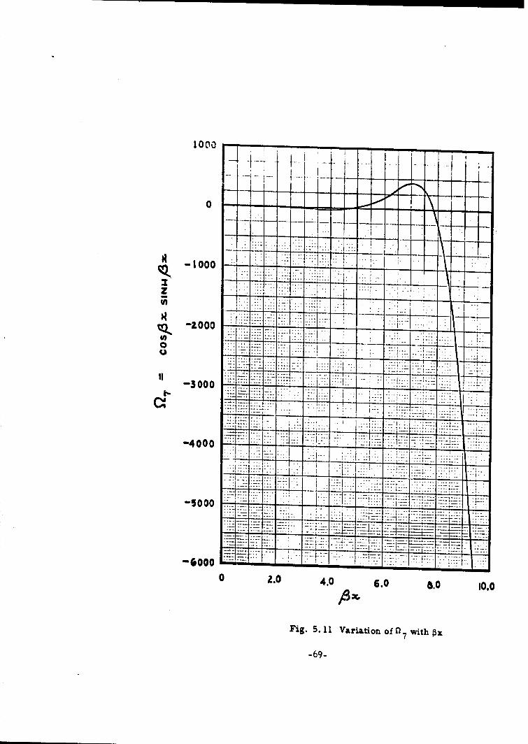
07 cos Px sinh px 69
0'8 cos Px cosh Px 70
sin 4 sih71
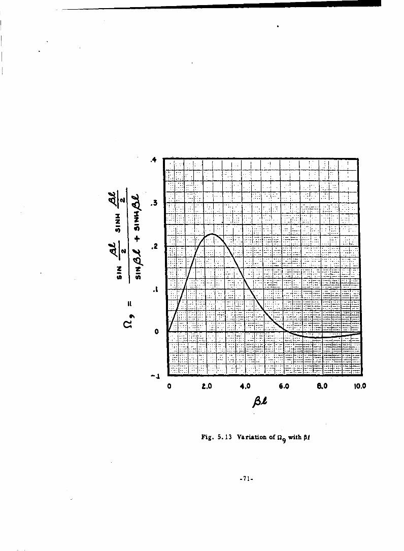
09 sin 01 + sinh m7
sin cosh 72
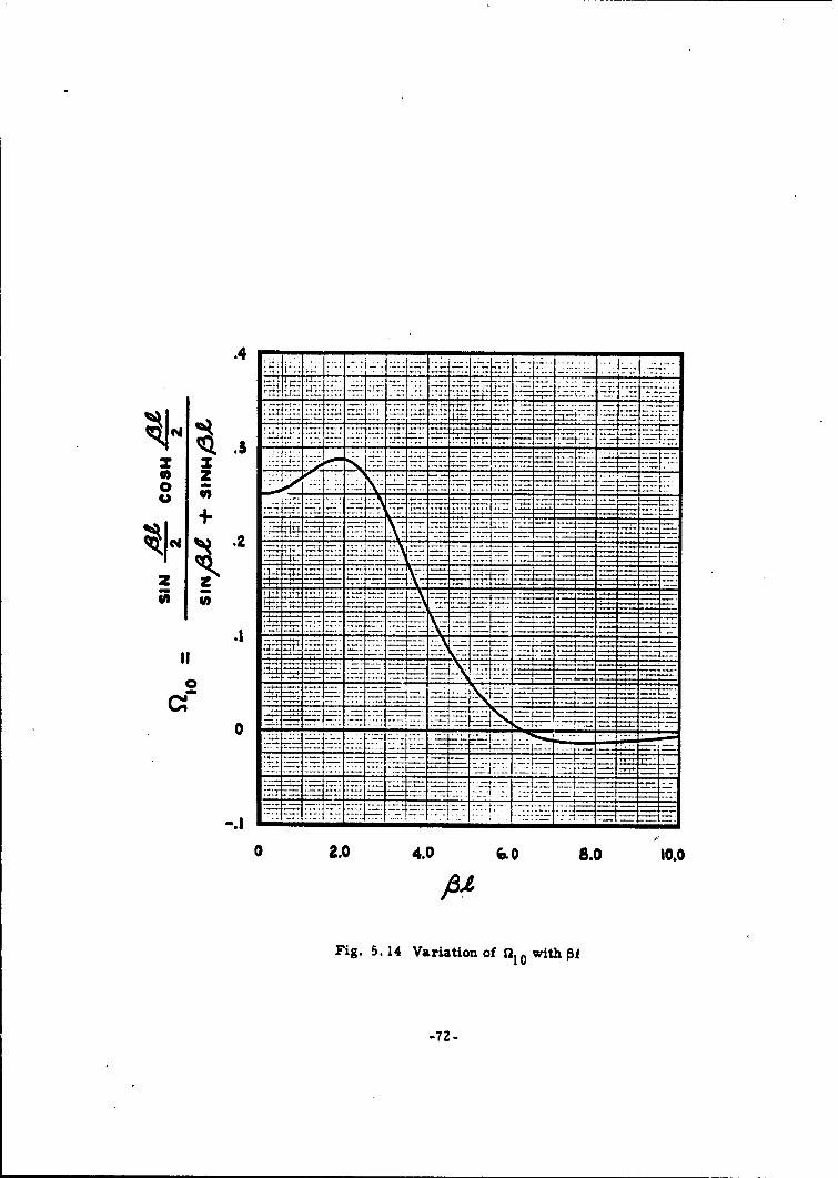
010 sin 531 + sinh PT
cos sinh -il sin Al +sinh PT
-14-
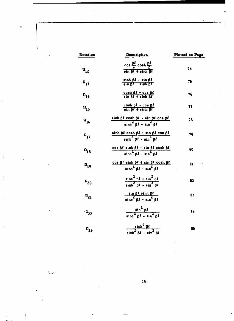
Notation Description Plotted on Page
cos 4cosh I4t'Iz min Of"+'er' BUF
sinh pl - sin of "5
1I3 sin of + Binh pI
cosh pf + cooA 76t•14 sin pi + sinh pl
cosh pf - Cos 77QI5 ~sin pi + sinh p! 7
sinh 01 cosh Of - sin Of coo OL 7816 msinh A PI sin 4 O
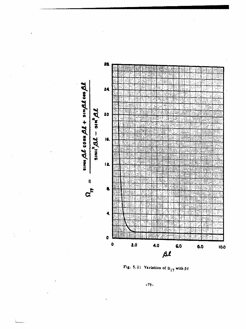
sinh pA cosh Of + sin of coo of 7917 sinh z Of sinz pA
cos Of sinhpl - sin el cosh PA 80sinh zt - sin AOf
coo Of sinh Of + sin elcoshh ,119 ~sinh z O - sin pA O
s0nh2 20O + sin 2fA 8zil20 sinhz Of - sin pi
sin Of sinh Of 83t21 sinh z Of! - sinz A O
91 in2 PI• 84'n2z sinhz pO -sin & O
023inh ! assinhz P - sinz Of
-15-

3.l.a Uniform Radial Shear o Lb Per Linear Inch of Circumference
at End of Long Circular Cylindrical Shell
60o
zo+. -
00
-TIo
00
r 2p D
Qo
0rx-): 0 -20 D
Qo
00
ZP D

3.1. b Uniform Radial Moment M In-Lob Per Linear Inch of Circumference
at End of Long Circular Cylindrical Shell
A =- =-r
GM 0
=h
ZMo ( 3 v +Zag 4)
M0ur = 4-
M 0
u ~Mo0
O(x=o) =
(-17
-17-

3. 1. c Short Circular Cylindrical Shell Bent by Forces Distributed Along
The Edges 31) Equal Edge Forces
0
ciz
I Z
(r A-
Phh
•x.= ••h-•1 8 Q9 - -5I4Qo 0 +3v
0 -F-I•- 5~ (59 PI"Z',ti . •:,- ("889 -"5017.)I
00u r 5 "n3 159 + 11 8 a12)
0 - 79 + "12 1 6 (g09 - 1).
Ur(x=-/- =1 . 2p3 D 14
0-8 (x 0 -18-D 1

Z) Unequal Edge Forces
01-
QQ 1
,, , 7•4&1(,QQ 1)-.
V-9- ( A .& al
2 p C> + ( SfLqg;Qg4 .nL 16a Y c)
-19-

j
Ur(x=O) = " • (n1802 + 0 16 0 1)2A D
0(x:0) = " zp DZz~1
Ur(x~f) 1 . T (a 1 6Q2 + 01801)2J3 D
1O(x~ = = (02oQC - Zn20Q1 )
3. 1. d Short Circular Cylindrical Shell Bent by Moments Distributed
Along the Edges
1) Equal Edge Moments
t~A 0 I za F4-
-20-

, 'A F, , ! II I i
., • . * ,.-• [(y,, i,.).i- (i,,-.ftif]
" -.L A (,.I ,)
Ie
(RI , A?+Al-~lo MA
2) Unequal Edge Moments
a.
-21-

II IA
t- I5 (MAI'7, MZSL19XI1e'*I)4 AVA(M 1 ,
+
--.. ..
e
- ~-i[M.R:- zt.,AA 21 ]
1> (M.A- 7 -M ,,) -
3. 2 Shells of Surfaces of Revolution
The following signs convention for the rotation and deflection are used:
Positive Deflection - radially inward with respect to the axisof revolution of the shell
Positive Rotation - clockwise viewing the upper cut of theshell
-22-

The nomenclature used in this section is:
WO = meridional stress
go = circumferential stress
u r radial displacement
9 : slope
S= angle between axis of revolution and norm al to wall
R = mean radius of circumference of discontinuity circle
RI = radius of curvature of the section perpendicular to the meridianat the point in question
R2 = radius of curvature of the meridional section
4 3(l-vz)
R Ih
D flexmal rigidity of the shell
Eh3
12(1-v
Qo = uniformly distributed circumferential shearing force at theshell edge perpendicular to the meridian•
M4 = uniformly distributed circumferential bending moment at theshell edge
= distance measured along the meridian of the shell from the edgeto the point in question and is positive away from the junction.
E= summation
v Y Poisson's ratio
-23-
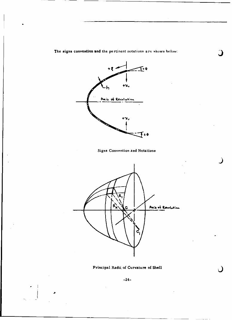
The signs convention and the pertinent notations are shlowt below: j
Signs Convention and Notations
Principal Radii, of Curvature of Shell
-24-

Q.
Notations in Shell Analysis
Where * signs occur in the expressions for stresses, the upper sign refersto the inner surface of the shell and the lower sign to the outer surface of the
shell.
3. 2. a Uniform Normal Shear 00 Lb Per Linear Inch of Circumference
at End
-25-
6RQO J•.- 4.
h' I
20 2 ~ 2 3(lV )Cot 0=io -- a IE- * vRfl~ w 03111r =-- 2 lp RqI 21•A
uo n0 00 - v cot oUr(lO) -. ZPR 0)
Q0 sin o0(t=o) - 2p D
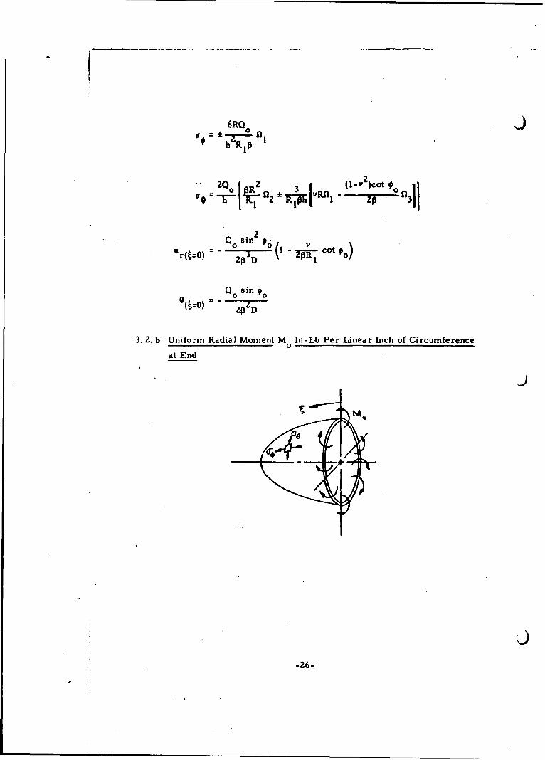
3.2. b Uniform Radial Moment M In-Lb Per Linear Inch of Circumference0
at End
-9
-26-
6RMel= -- R 3
SR1
M. 0U r(tO) - sin
M0l~) 0 •--
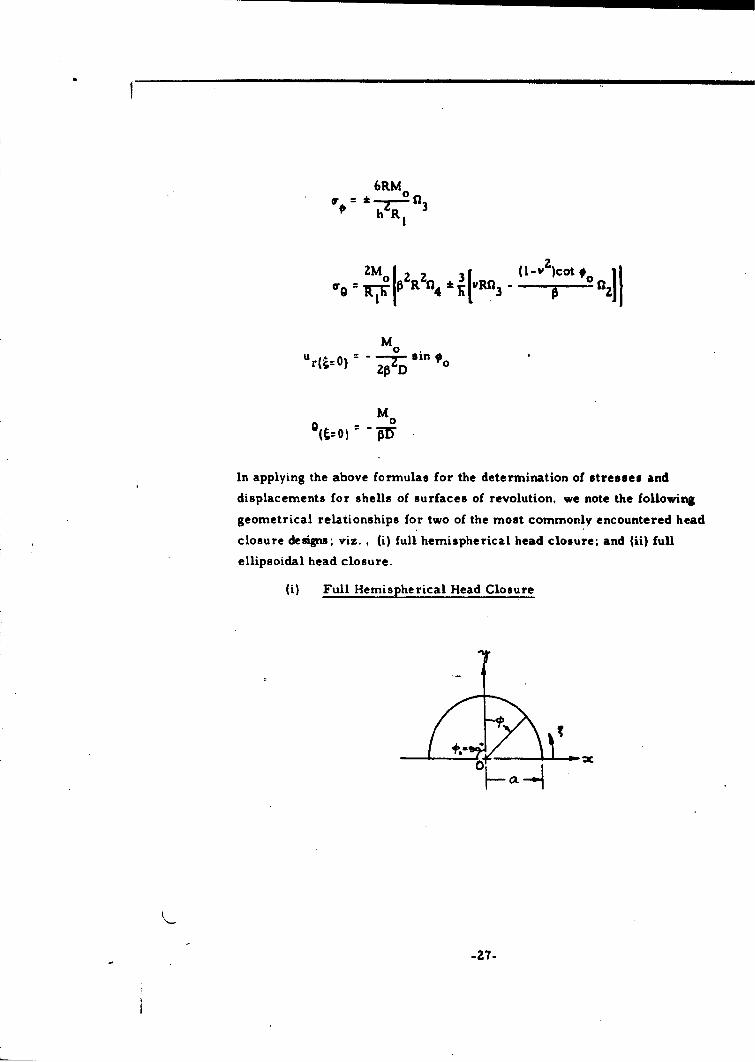
In applying the above formulas for the determination of stresses and
displacements for shells of surfaces of revolution, we note the following
geometrical relationships for two of the most commonly encountered head
closure designs; viz. , (i) full hemispherical head closure; and (ii) full
ellipsoidal head closure.
(i) Full Hemispherical Head Closure
-27-
t10 FI-
If a is the radius to the middle surface of the hemispherical shell, we have Jthe following geometrical relationships:
R R2 =R a
4 3(1- v 2
ah
00 90
sin o 0= I
cot o 0
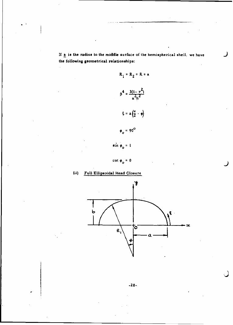
(ii) Full Ellipsoidal Head Closure
-28-
I
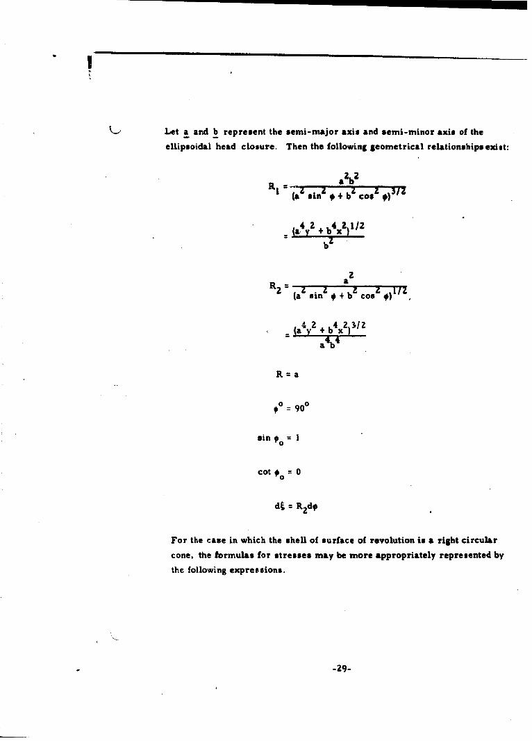
Let a and b represent the semi-major axis and semi-minor axis of the
ellipsoidal head closure. Then the followimg geometrical relationships exist:
aZb2l~i • b 1 311(az sin q+b c Cos
4 4(a4y2 ÷ 14xZ) I/2
bz
2R 2 z : z ) 1 7 7
(a sin # + b co. 0)
=(a yz + b xZ)
a~b
R=a
o 0 90°
sin =1
cot = 0
dt R•zd
For the case in which the shell of surface of revolution is a right circular
cone, the formulas for stresses may be more appropriately represented by
the following expressions.
-29-

3. 2. c Uniform Radial Shear o Lb Per Linear Inch of Circumference at
End of Right Circular Conical Shell
ICA
"S z
w h e r e C ---
QoSe., ?, 1- I. be:; i. zv[Qe.:, ;.)¶i Ie~L3 - V [( -
S4
-30-
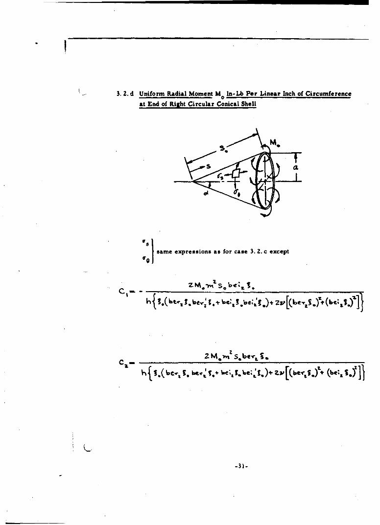
3.2. d Uniform Radial Moment M In-Lb Per Linear Inch of Circumference0
at End of Right Circular Conical Shell
:;sI same expressions as for case 3. 2. c except
C.4 mell so ev2.
•rIt
h{.(~~~vi~J . M.r * 'he~ be- .
Cz=
-31-

3. 2. e Bending Stresses in Cone Loaded by Uniform Internal Pressure p
When there are no edge shears or moments, but the edge support
condition is such that it is not the same as that necessary for the membrane
condition, bending stresses will be introduced. The magnitudes of these
stresses may be obtained from the following equations:
C41 ;e 1 -2-( + k
OS4I[zev ? 7P(z % , S;2 )]*
C 6, e -a- (Z 1cI+VI evt v ý1,v )fI.
where 2
{z
4{.(6er .6eV-" 1. +be+2V b .S.+ (b-
-32-

I3.3. Circular Plate with Uniform Edge Moment M. In-Lb Per Unit Inch of
Circumference
6Mo M
At Any Point: or 6Mr=h upper sign refers to the inner surface
6M| and lower sign to the outer surface.
=h
6 (l- v)(a2- R ) M0Atft: ¥ Eh3
-33-
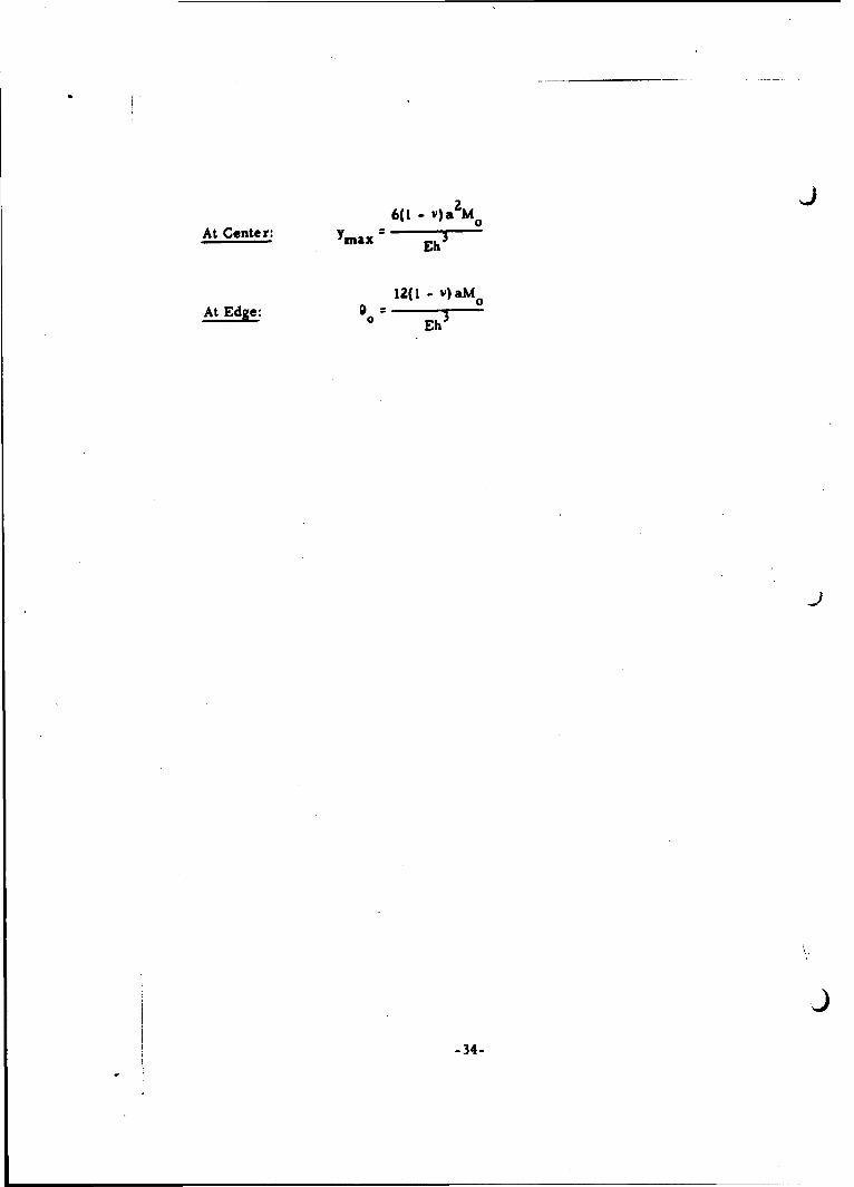
6(1 - v) a m 0
At Center: Ymax 2 Eh 3
12(1 - v) aM
At Edge: 0 ov
-Eh3
-34-
4. SOLUTIONS FOR DISCONTINUITY SHEAR FORCESAND BENDING MOMENTS
A tabulation of solutions for discontinuity shear forces and bending
moments for pressure vessel configurations of practical interest under
the action of internal pressure is offered in this section. The positive
sense of these discontinuity forces is defined in each of the figures
associated with the particular pressure vessel configuration investigated.
The following nomenclature is used in this section:
a = N-mean radius of curvature of the circular cylinder, inches;
p internal pressure, psi;
E = modulus of elasticity, psi;
v - Poisson's ratio
Q0 = uniformly distributed circumferential shearing force atthe junction, lb per inch;
M = uniformly distributed circumferential bending moment at0 the junction, in. -lb per inch
h = shell thickness, inch;
4 3(1 - v )a7~
Eh.3D. -- h.
12(1 - v )
- flexmal rigidity of the shell
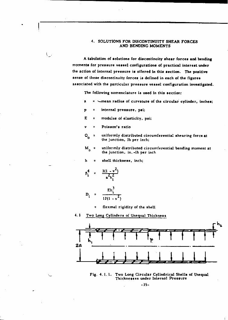
4. 1 Two Long Cylinders of Unequal Thickness
Fig. 4. 1. 1. Two Long Circular Cylindrical Shells of UnequalThicknesses under Internal Pressure
-35-
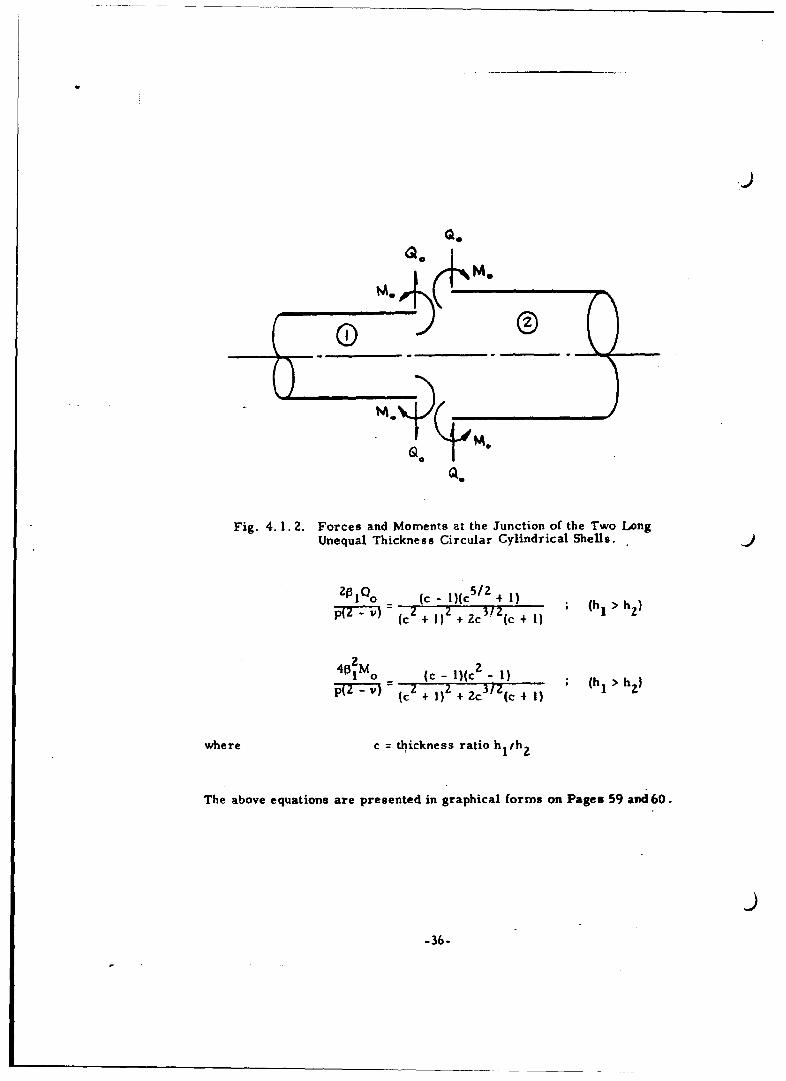
Q0
Fig. 4.1. 2. Forces and Moments at the Junction of the Two LongUnequal Thickness Circular Cylindrical Shells. J
zOI~ o (c - i)(c5/Z + 1)S=T ( + 2 + c3/ ++ ) ; (h2 >1h2 )
4I2Mo (c - l)(cz 1) ;(hI > h}:,=VI (c + 1) 4- 2c 3/(c +
where c = thickness ratio hl/h
The above equations are presented in graphical forms on Pages 59 and60.
-36-
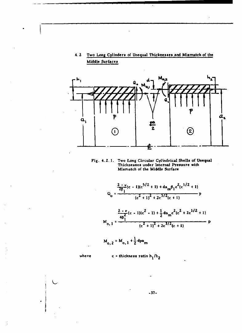
4. 2 Two Long Cylinders of Unequal Thicknesses and Mismatch of the
Middle Surfaces
"CL I I pa.A
Fig. 4. 2. 1. Two Long Circular Cylindrical Shells of UnequalThicknesses under Internal Pressure withMismatch of the Middle Surface
2-(c - l)(c5 Z + 1) + dampic 2(c1/ 2 + 1)QC) FT 2 3/Z n
0 (c + 1) + 2c (c + l)
2-v - 2) 1 Z 1/2.1- c Mc -l)(c +) +-damC cc c 1)2 mn
M 0.1 40 1 (cz + 1)z + 2c 3/Z c + 11 P
Mo, 2 M 0 1 +dpam
where c thickness ratio h1/h2
-37-

Graphs of Qo0dam Iplp and ZM0 , l/damp as a function of hI/h 2 are presented
on Pages 61 and 6Z. The Q and Mo, 1 thus computed may be superposed to
those calculated for Case 4. 1.
4.3 Long Circular Cylinder with Circumferential Ring Stiffeners
4z.
>9
Fig. 4. 3. 1. Long Circular Cylinder with CircumferentialRing Stiffeners under Internal Pressure
MO Q.
t IQ0 ~
Fig. 4. 3. 2. Forces and Moments at the Junction of the CircularCylindrical Shell and the Circumferential RingStiffener
-38-

Qo = Z2M
4. 4 Long Circular Cylindrical Shell with Many Equidistant Circumferential
Ring Stiffeners
A, c(Twft)
Fig. 4.4. 1. Long Circular Cylindrical Shell with Many EquidistantRing Stiffeners under Internal Pressure
[a (I__h______+_a' __+__
h0b ÷ aZ÷
o40n [h/b' + I) + a14-02O3
Qo= 2pnl 5 Mo
-39-
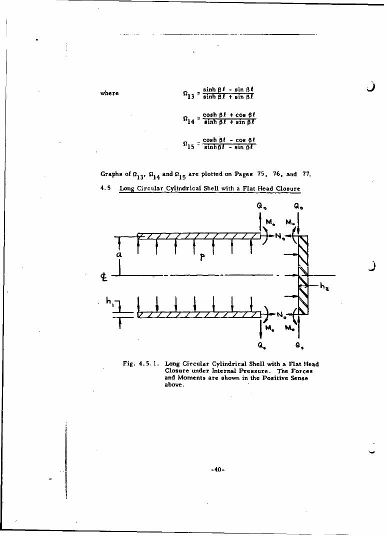
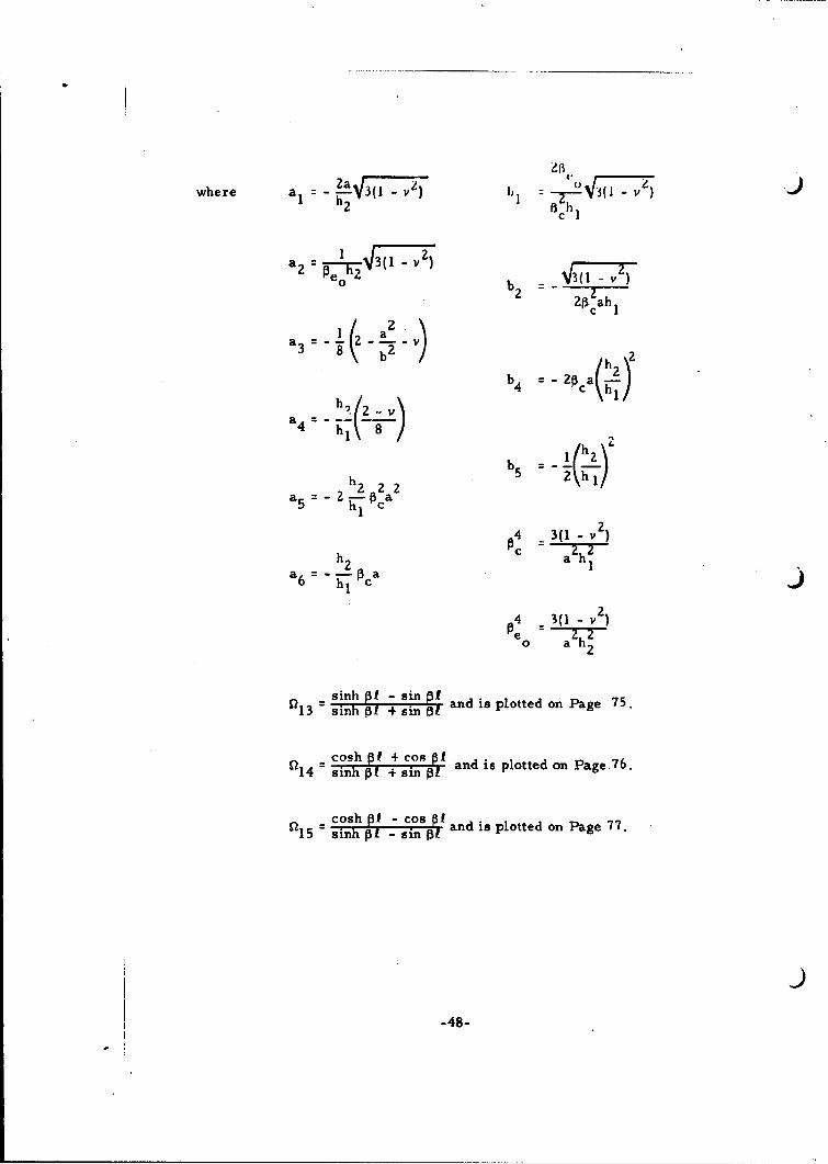
where a sinh 1 - sin B fwhre•13 :sinh B I + sin Bf
cosh 0I + cos of
14 =sinh p + sin G=
cosh of - cos ofis5 =sinh p - sin =5
Graphs of a13 , 1 1 4 andf?1 5 are plotted on Pages 75, 76, and 77.
4. 5 Long Circular Cylindrical Shell with a Flat Head Closure
O• Q.
7 7 7 7 /- 7/N.-
IM.Qe Q.
Fig. 4.5. 1. Long Circular Cylindrical Shell with a Flat HeadClosire under Internal Pressure. The Forcesand Moments are shown in the Positive Senseabove.
-40-

C (a3 " a4 ) (b, - b4) + b3 (a4 ) Io-ZL(a I a S) (5z -Ibs (a 2 aZ- 6) (b,- b 4)]
(a41- a3) (b 2 - bs) + b3(a 2 "a6 ) a
M° 4pa' ' (a, - a,) (bj "bs ( a. --a6} {b "4)
where a=6- (I-v) b 6( v)
a -= 20( - v) 3(l - v)
3a {I-V)a3 -Tb 230-v
a 3(z -v)
b4 = 26a(h2 hA1 )2
a5 2 h-2-2a2 b I(hz/h)2h,55 T 2 1
h z 143(l - v2a6 'h-l pa =a zhZ"
-41-
I

4. 6 Short Circular Cylindrical Shell with Equal Thickness Flat Head
Closures
Q A M 0 0 .N ~
me MOM
N.
Gso
Fig. 4.6. 1. Short Circular Cylindrical Shell with Equal Thickness JFlat Head Closures under Internal Pressure. TheForces and Moments are shown in the Positive Senseabove.
r a -a)( ba)+b(a Q - a)Q0 = Zp (a 3 a 4 )b-b 4 2 15) b 3 ( 5 13 .1 I
S L(al. a S1 3 ) (b2" b51 3 ) . (a 2 -a 6(6 14 ) (bI . b4 f415 1
= 4pa2 (a4- a 3 ) (b2 - b5 0 13 ) + b3(a 2- a6 0 14 ) 1
Mo( (a "-aS1 3) (b2 -b 5 l 3 ) " (a2 - a6 "Q14 ) (b "b41215
where aI through a6 , bI throughb 5,and P have been previously defined
(Case 4.5) and R13, S114' and 115 are defined in Case 4.4.
-42-
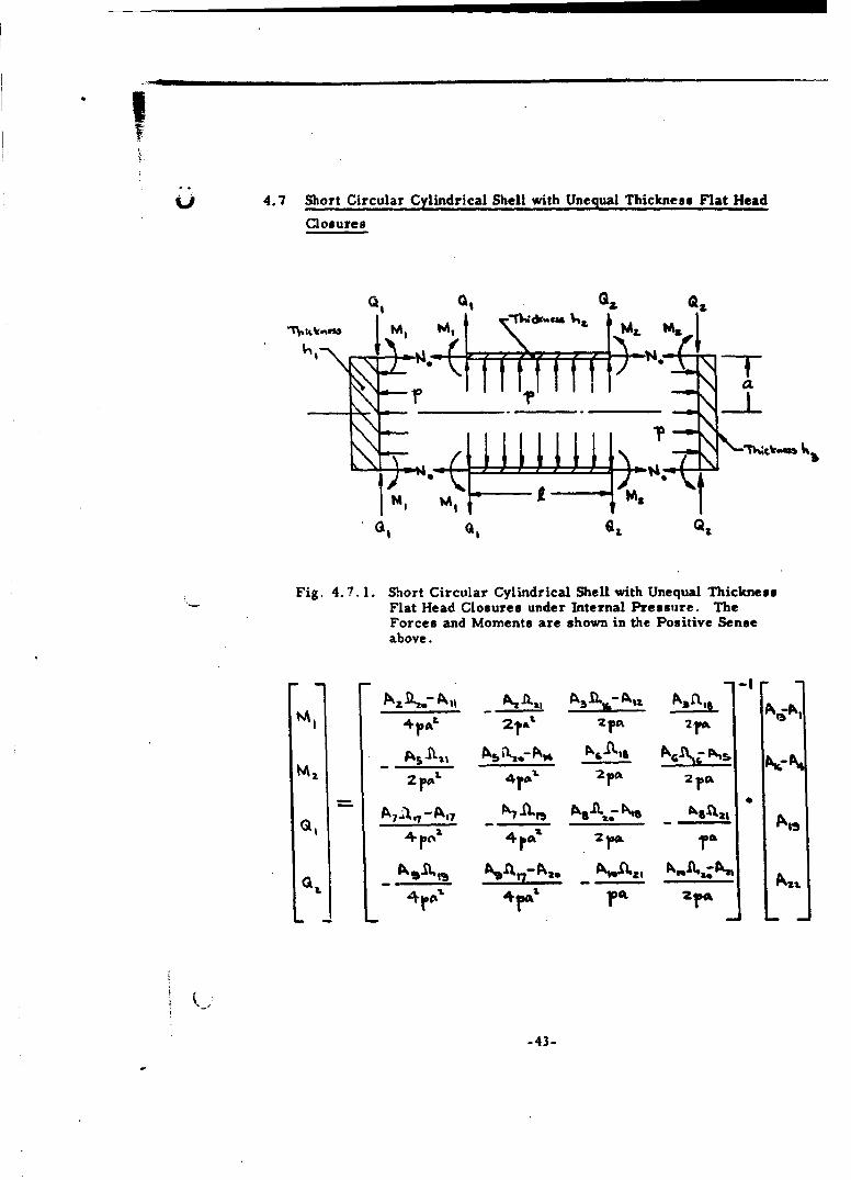
4.7 Short Circular Cylindrical Shell with Unequal Thickness Flat Head
Closures
Q1I
M1 M1Q•Q
Fig. 4.7. 1. Short Circular Cylindrical Shell with Unequal ThicknessFlat Head Closures under Internal Pressure. TheForces and Moments are shown in the Positive Senseabove.
P's A,.l,., A 1,. Fkf• NS's1,C 1.A
2. rt' 4r1'. ..ro 2 pO
Q AAq~I7 -A ~A;' -N
L.. .. .4
L ,,L
-43-
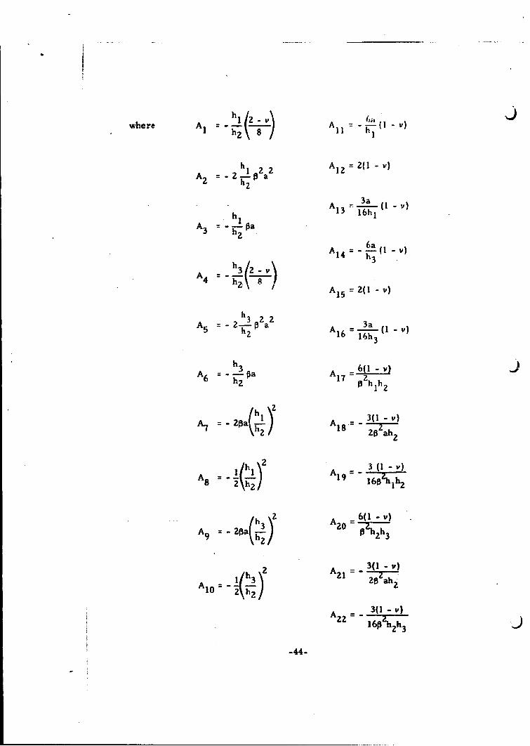
--I Y l
A 2 = 2 h p 2a 2 AI2 = 2 (1 - v)A2 h'22
3aA1 3 -- (1 - v)
h,1 16hl• 1
A3 = "h 1 a
6a v)AI 4 =-( -ih )
A 234 A 1 5 = 2(1- v)
A5 ~-2-h3 02a 2 3 )A5 h2 2 (I3a
A 6 (1 -v)
6 h 2
(hi)2 3(1 - v)A \h 2 A 2
A2A = - 3s A 0)8 2 h219 160'-hlh2
h 2 6(1 - v)A9=20a( 3) A2 0 p=6(1-ih)
2 A = 3(1 - v)
A I h3) 21 26 zAh2A1O 2 h 2•h
3(1 - v)
22 160 2h 3
-44-

I
sinh Of cosh Of - sin O1 cos at and is plotted on Page 78.1J ill6 : sinh2 1O s - of
sinh Of cosh Of + sin Of coo 01 and is plotted on Page 79.917 = sinh zO - sin 0o1
cos PO sinh Pf - sin at cosh 01 and is plotted on Page 80.~18 z .20i'•18 = sinhZ pf sin--Of
sin .3O cosh Of + cos of sinh of and is plotted on Page 81.19 sinhz pf - sin2 zO
Q eOnh 2 Of sin 2 and is plotted on Page 82.
uz sinh $3o - sin zof
.sin O sinh and is plotted on Page 83.21sinh2 PI - sin2 pf
4.8 Long Circular Cylindrical Shell with an Ellipsoidal Head Closure
Qo e
Q.
Fig. 4.8. 1. Long Circular Cylindrical Shell with an Ellipsoidal HeadClosure under Internal Pressure. The Forces andMoments are shown in the Positive Sense above.
-45-

J
afc~ pC C) +
"______, __- _____-, ___ ,=, -. - - •J
where 4 3(1 - 2)
Eh 3
whreD3 Eh1
D 12 (1 - vI
The above expressions for Q and M are plotted as functions of hIAh2
on Pages 59 and 60.
-46-

4. 9 Short Circular Cylindrical Shell with Equal Thickness Ellipsoidal
Head Closures
Qo N-4 L'I l a
Fig. 4.9. 1. Short Circular Cylindrical Shell with Equal ThicknessEllipsoidal Head Closures under Internal Pressure.The Forces and Moments are shown in the PositiveSense. above.
Q0 a (a 3 - a 4 ) (b1 - b4 S) Q Jlo p (a a 5 S21 3 ) (b2 - bs25 ) ta2- a 6 Q.21 4)(b I. b4 1R1 5 ) J
-47.
where a2 - e 3 (1 " v2) =( -La vz)I h)r3(I v ) bI~
a c a 1
h1\8a/
a h 23(I/
4 eZV3(1 7)
h ah
a6 "• O a 2h9a5 -- 2 -- v
5 c
4 3(1 - v2)
e2 aha 6 hi C1
2
sinh PI - sin • and is plotted on Page 75.13 = sinhOf +" sinRT,
4 cosih p I + cosi and is plotted on Page 76.
5 cosh t -cosi and is plotted on Page 77.
-48-

4. 10 Short Circular Cylindrical Shell with Unequal Thickness Ellipsoidal
Head Closures
SG I
M 1 1 , % M 1.
0 1LL
Fig. 4. 10. 1. Short Circular Cylindrical Shell with UnequalThickness Ellipsoidal Head Closures underInternal Pressure. The Forces and Momentsare shown in the Positive Sense above.
A21 20-All A2PZl %A 16 -A12 Afl 18 AA
M 4pa pa" pa Zpa 13
'5 2 1 A5 Z0A 14 A6p18 a6 16 "A15M2 2pa' '±paZ Zpa Zpa 1'6 = A4
AM AA A~Al -717 17 -p 79 820 18 - A821 4
ZZZZpa Zpa4pa 4pa
A ll 1-9 A -.ZI
7___ 97 1. *19 1'0 218 A 0 ~ 0 - 2Ql a . . ..... 2- pa0
4pa 2 4pa
-49-
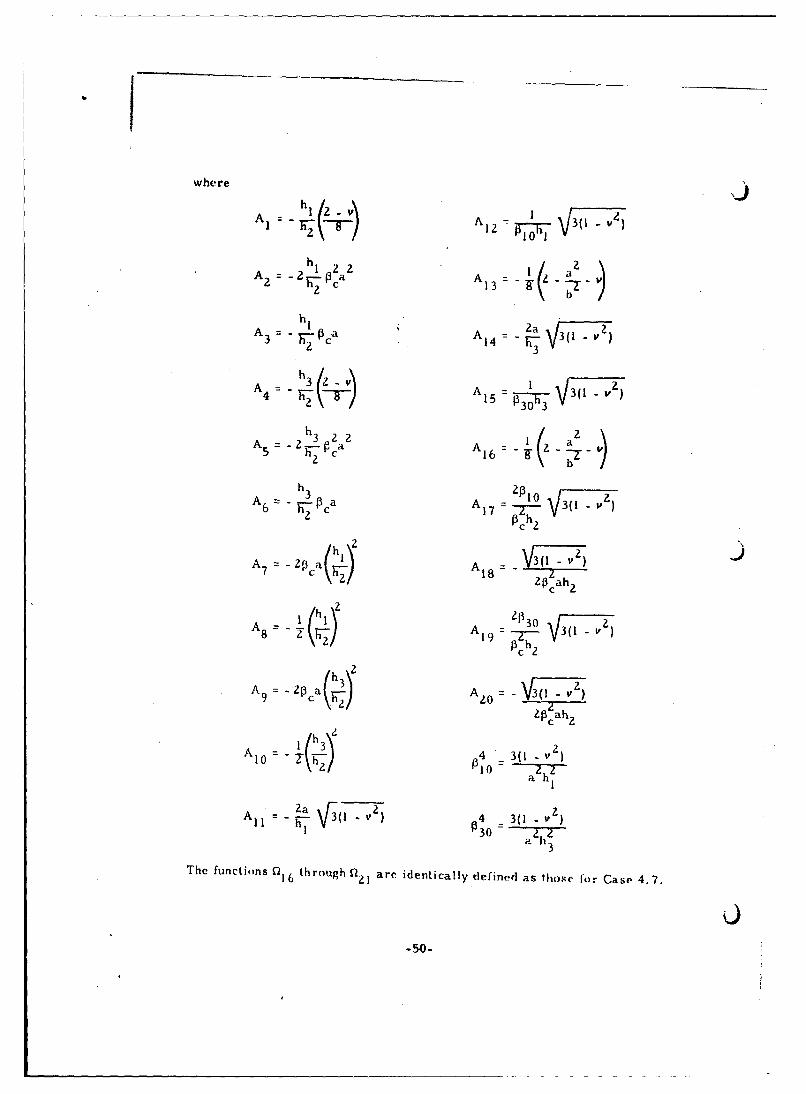
where
•, : -• • -/ ,• -- • ;, 3(1-v I,
A hi A V3a (
"( I4J 3(JI_)A4 3 C A 1 3 35 2h 3
h• 1 a
A- A T3 3(I-)4 RZ (i~v-)15 = P 30 h3
h3 2 2 aA 5 = P-ca A = Z-
A6 3 P • a A 0 = -• (1 -vo
=- c 317 = = V3 (
p chh 2 2
h h
A - -ZP-1 A 1 = - 3( 1- v
2 17o 2
c 2
Z030 - -
-h A19 =h = 3(I-v Z
h 3()
h hA = 3 4a r
10 h 3(1 - v )
The functions Q 16 through 0 are identically defined as ithose for Case 4.7.
-50-

4. 11 Long Circular Cylindrical Shell with a Hemispherical Head Closure
t M. O
Q. e
Fig. 4. 11. 1. Long Circular Cylindrical Shell with a HemisphericalHead Closure under Internal Pressure. The forcesand moments are shown in the positive sense above.
ze Irk \ ,
(A_ _ __ _ _ _ (ýL.7 Zc[ o 4 1 1[+ 11 1- -L
where0
-51-

4. 12 Short Circular Cylindrical Shell with .qual "'hiclene-ss hrrmispheric'id )Head Closures
0.G. Q. ,
Fig. 4. 12. 1. Short Circular Cylindrical Shell with EqualThickness Hemispherical Head Closuresunder Internal Pressure. The Forces andMoments are shown in the Positive Senseabove.
The formulas for Qo and M for this case are identical to those for Case 4. 9.
The dimensionless influence numbers al, a, . , bI, • . . b 5 etc.,
are also identical with the exception of a 3, where for this case,
Ia3 :--•(I-v•)
-58
-52-
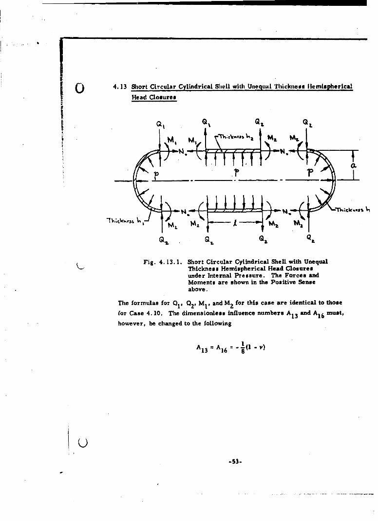
4.13 Short Circular Cylindrical Shell with Unequal Thickness tlemispherical
Head Closures
MzM
Fig., Q Q
Fig. 4.13. 1. Short Circular Cylindrical Shell with Unequal"Thickness Hemispherical Head Closuresunder Internal Pressure. The Forces andMoments are shown in the Positive Senseabove.
The formulas for Q01 Q29 Mi and Mz for this case are identical to those
for Case 4. 10. The dimensionless influence numbers A1 3 and A1 6 must,
however, be changed to the following
13 = A16 - -8(1 -
-53-

4.14 Long Circular Cylindrical Shell with a Conical Head Closure U
Q0
Qo a
Fig. 4.14. 1. Long Circular Cylindrical Shell with a Conical HeadClosure under Internal Pressure. The Forces andMoments are shown in the Positive Sense above.
GL 6.[ ( Co +c) i (11.54 QC)( 6-) 6 1)
-(01 + C)( s-6z)* (t61- 64)(aCt a.)J
where a 6= .
0-54-

6.5 +
4 2.
A - ,(1~ie~ T 6c.t. - 6e;~ t 6ev.
bey 9. ~ber 2 +,)
G (6e.7 1) z + 6e 2necc
,,14= -27p a
64~
6t
0 PC

Graphs of al., 1,, h,, and h ;is~ a function of arid ti for v of (*30
are plotted and are presented on Pages 8 6 throtigh 89,
4. 15 Short Circuilar Cylindrical Shell with Unequal Thickness hfead Clostires
of Ellipsoidal and Conical Shape
GLL
Fig. 4. 15. 1. Short Circular Cylindrical Shell with Unequal ThicknessHead Closures of Ellipsoidal and Conical Shape underInternal Pressure. The Forces and Moments areshown in the Positive Sense above.
A7_TL__A, - zi
Q ~AhSAU As~ci,?l A PNAI,,t a. -
-56-

( a(wherh A2 =-
_22 .l••
A 2 h A8
A5 3 . •A 2 3W2 9
h5 31 - v\ 22
t4 -2 pC A1 1 h3(
A . •/1 2a
AI( 4 3(Z)v
13 8 J2ah
-57-AI8 Zoa

0The functions 016 through n21 are identical to those defined in Case 4.7.
4.16 Short Circular Cylindrical Shell with Unequal Thickness Head Closures
of Hemispherical and Conical Shape
1, Z.M 1M2 z •
' l----
Fig. 4. 16. 1. Short Circular Cylindrical Shell with Unequal ThicknessHead Closures of Hemispherical and Conical Shapeunder Internal Pressure. The Forces and Moments areshown in the Positive Sense above.
The formulas for QI' Q2' MIP and M2 for this configuration are identical to
those for Case 4. 15 except that A1 3 is now defined by
1(3
A13 8 v)
-58-

5. GRAPHICAL PRESENTATION OF PERTINENTPARAMETERS
1.0 m ~ .m r
.7-
0- L- 4. L
C,,
h2.. . . . . . . .. . . .
4i, 1, 1. -ai , 1 en1ing Mo et ih T ic n s7 ai o
Tw ogClnrclSel of Unequal Th icnsz~z~iEKA+.59-

ig ii
I VIBM 1 10 IFI'l",R0
'Opc1MM
.........
0 L ~ 4
Fig. 5. 2 Variation of Ju~nctu~re S'ý-e, ring Forces w;-I Tr~ckness Rt-;.o forTwo Long Cylindrlc4]a S)~ells of Urieq .il Tl-.-.cknese
-60-

.2
I77'
6 is
.2 ;H if.4.5
C : -1:'ý t I'll:1
Fig.~ ~ ~ ~ I 5.3 1ulto of1 3uctar Ihalg o s with TR1 nu atoDetMmacofil Middl Su. ac1 Only Nf Two LonM Cydrio nqa
U Thickess (tobe use 1n cwJntill wiqFi.5.
I-61.

-* -77- - - 177
.7 - --- - .---- --I 4 4'' 44
4L40 . ... ... ..
4.7-- - .
: / 7,4,
- L-I
Fig. .4 Vaito of JucueBnigM mnswihTikesRto4j
to Msmach f MidleSurace Onl ofTwoLongCylndes 4,
Uneua Thcns (to be use in -oucto wit Fi.
2 -- -- 62-

*17!!I
I !t I
.5 .
ii! V~ 14
... ... . .. m
.................................................. .......
UL 4.0 6.0 8.0 1.0
Fig.~~~~~~~ S.5Vraino ihO
-63-i r p

104
j4 WI Mut[f
A ~M I MIN,0 .06, IOA,
*~~~~~~ Fi.56 aitinh~wt~-6 -W 1
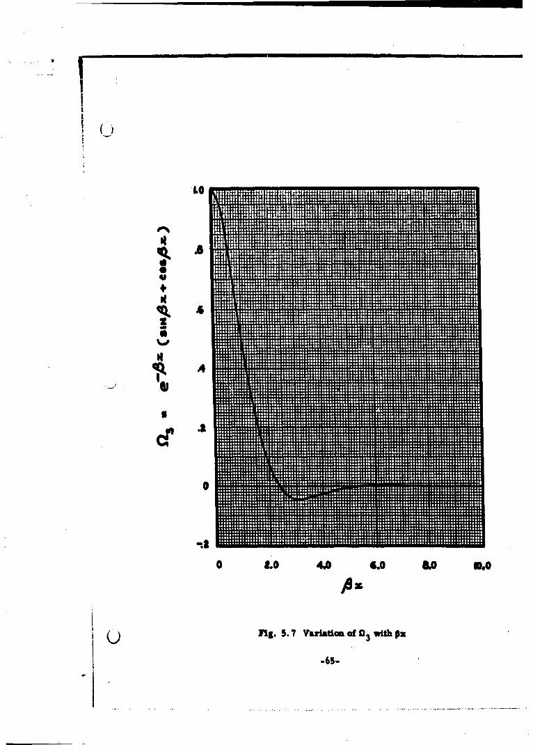
r ¶r
.65

m m
I .. .....
.8
I
U•,
o .4
0 I9.0 4.0 O. 0.
Fig. S. 8 Variation of a with Ox-4
-66

1000 . ... ....___ ___
011:
1600
II
400
0 1.0 4.0 6.0 &010.0
Fig. 5. 9 Variation of P5 with px
-67-

16000 .t
1~00 L r~~
Ito77- -
0~. -L*0001.
z bo - ~ --------
-600
'5 0 2. 4. 608 - 1.
-6--
1000
z
-aooo
II -3000
-4 00 0
-5000 7:
i~o -E- 7 7
0 2.0 4.0 6.0 8.0 10.0
Ax.
Fig. 5.11 Variation of [27with AX
-69-

10001
-1- --. 1000.--- -t-.-K.L=-
-2000~
0~~t r - .7-*=::7:7 1u
-2000 tj::J
-4000 _4
-0020 40 n 600 A .0 i00
Fig. S. 1 Variation of 11 wthP
_70-
.3.
.2 -
z
7_1 E.-7 -7::
0 .0 4.0 6.0 8010.0
Fig. 5.13 Variation ofa 9 with P1
-71-
Z7:o= 7
NA
o2.0 4.0 6.0 8.0 10.0
Fig. 5. 14 Variation of a 1 0 with PI
-72-

3- ... ...-
.2
II- --.-
.- -:ý
,
-- 4-.:
o~ 91-
-. 7.- - --. 1.----7.. - 4. - - .1 F
0 .04. 6J.0 8.0. 10.0
Fig. 5. 15 Variation of nwith P.I
-73.

1.
-" 7 :' I0-
SkS
-74

tit-.
1.0
0 2.0 4.0 6.0 8.0 10.0
Fig. 5. 17 Variation ofill with 1I
-75-

B. - - - -
0 Zý
+44
o. 4.0 6.0 8.0 10.0
Fig: 5. 18 Variation of 114with Al
-76-

77 - -7
- ---- - - -
- J
0 2.0 4.0 6.0 8.0 10.0
Fig. 5.19 Variation of 0,wi.th of
-77 -

~~F-7
0
0 2.0 4.0 6.0 6.0 10.0
Fig. 5. 20 Variation ofn 1 6 with I
-78-
7 T
4..
-7.70
r-77;----
CZZ -
0 2.0 4.0 6.0 8.0 104o
Fig. 5.21 Variation of n 1 7 with of
-79.

.. .... ..7 7.
"!7 4 .. .... ..
... ... . - .I- 2 -.8
IQ i=: L
I.' ~ ý7 ý jt - _
-2.0__m-0 2.0 4.0 6.0 8.0 10.0
PAt
Fig. 5. 22 Variation of S18with 3l
-80-

Z4. -1w* - ill- ittIt I 'Ii' "rH-
z z S
z
-71=
00
-4
0 2.0 4.0 6.0 860 10.0
At2Fig. 5.23 Variation of a 9with 01

E14=
I L
0.04.0 6.0 6.010
Fig, 5.24 Variation ofp 2 0 with pi
-83-

4 7=
.l .- ... ..
0 3.0 .4.0 6.0 &.0 50.0
Fig. 5.25 Variation of ai with 01
-83.

- 4-
0.0 4.0 8.0 0 10.0
Fig. 5. 26 Variation~ of Cl22 with Pf
-84-

444 ~ ~ ~ ... .. .I .... . ......
.~. ... .. . ... . I .. 1 1.i........ 4 .0 60 8.0.0.........
Fig 5 Z7 ......o..f........
-85

0 W I"R 1 1ii]'f 411 RIVII: OWR .N HM I IM
115N II: V HW1111111I0 l"11MNAi
-t0
400 f50 I0 SO 90
F~.Ig I, " .5Z.aitnfa Moeo wth tMI
.86-

-400 Mt 111. a ON~j
+4 +H
-800 ~~ .w -otllt
- l";11 1 i t N*
-2000 ..
-2400 . ;44 ,tON
w~e .j~ ..M , 3A
V. w Is1 . WXI404 50 0 ,0 80 90*0
Fi. .Z VatIonofa ##t .1#1 0ouec ý ZIE
-,M = NM-87-

0
-I00
'• -400
-400
40 o0 60 70 80 go 100
flu. S. 30 Variation of 4b1 cot a with g
-88-

Soo
A99
4498 . .. 1 ...
.. .........
Fig..... . 5. 31 Vaito of wih.
-89- ... -
REFERENCES
1. Galletly, G. D. , "Influence Coefficients and Pressure VesselAnalysis, " Journal of Engineering for Industry, August 1960.
2. Watts, G. W. , and Lang, H. A. , "Stresses in a Pressure Vesselwith a Conical Head, " Trans.ASME, 1952.
3. Taylor, C. E., and Wenk, E., "Analysis of Stresses in the ConicalElements of Shell Structures, " Proceedings of the Second U.S.National Congress of Applied Mechanics, ASME, New York, 1955.
4. Timo.henko, S. , and Woinowsky-Krieger, S., "Theory of Platesand Shells" (McGraw-Hill Book Co., Inc. , New York, 1959),Second Edition.
5. Watts, G. W., and Lang, H. A., "The Stresses in a PressureVessel with a Flat Head Closure, " ASME Collected Papers(1927-1959) on Pressure Vessel and Piping Design.
6. Au, N. N., "Discontinuity Stresses in Pressure Vessels-ShortCircular Cylindrical Shell with Ellipsoidal Head Closure, Part 2-Shells of Unequal Thickness, " 31 August 1961; Aerospace CorporationReport No. TDR-594(1108)TN-2.
7. Lowell, H. H.:, "Tables of the Dessel-Kelvin Functions Ber, Bei, Ker,Kei, and their Derivatives for the Argument Range 0 (0. 01) 107. 50,"NASA TR R-3Z, 1959.
8. Nosova, L. N., "Tables of Thomson Functions and their FirstDerivatives," (Pergamon Press, New York, 1961).
9. Fligge, W. , "Stresses in Shells," Springer-Verlag, Berlin/G6ttinge r/Heidelberg, 1960.
10. Jones, R. H. and Orange, T. W. , "Theoretical Elastic StressDistributions Arising from Discontinuities and Edge Loads inSeveral Shell-Type Structures," NASA TR R-103, 1961.
-90-

APPENDIX
DERIVATION OF FORMULAS
A. BENDING STRESSES IN SHELLS
1. Symmetrical Deformation of Circular Cylindrical Shells
The differential equation governing the symmetrical deformation
of circular cylindrical shells in accordance with the classical shell theory is
(D +7 U Z (A. 1.1)dxa
wkIere D flexural rigidity of the shell
.3- Eh (A.1.Z)
1201 - V2
Z = load intensity
h = thickness of shell
a = mean radius of curvature
E = Young's modulus of elasticity
v = Poisson's ratio
u = radial displacementr
In the case of uniform shell thickness, Eq. (A. 1. 1) becomes
D d Au ol E (2 r+ (2 lr3Z
dx a
A-1

Using the notation
4 Eh 3(l - v(A.1.4)
4a D a h
Equation (A. 1. 3) can be represented in the simplified form
d4u
r 44 Ur Z= (A. 1. 5)
dx
for which the solution is
Ur = ex (C 1 cos Px + C2 sin Px) + e X (C3 cos Px + C4 sin Px) + f(x) (A. 1.6)
In Eq. (A. 1.6), f(x) is a particular solution and C1 , C2, C , and C4 are the
constants of integration which must be determined in each particular case
from the conditions at the ends of the cylinder.
The expressions for the membrane forces, bending moments, and transverse
shearing force associated with the symmetrical deformation of circular
cylindrical shells are
N Eh(~~~
M= -E-
x 2 .
dxu
Mx =Ddx2r
(cont.)
A-Z

d2 uM 0 = V -rD- -
dxc
d3 ur
Qx D= D--(A. 1.7)dx
In the case where there is no pressure Z distributed over the surface of the
shell and if the end condition is such that Nx = 0, then f(x) = 0 in Eq. (A. 1.6).
Furthermore, for long cylindrical shell@ subjected to loading conditions such
that for large positive values of x, the deflection is finite, C1 C2 0 and
Eq. (A. 1.6) reduces to
Ur = e'Px (C3 cos Px + C4 sin Px) (A. 1.8)
For N x 0, the first expression of Eq. (A. 1. 7) givesx
du uX = V -a-
- - a
which when substituted into the expression for N. yields
EhuN a r (A. 1. 9)
The stresses in the shell are given by the expressions
6 M
h
NO 6Mo
W- N -6 (A.1.10)h
A-3

where o" = meridional stress
og = circumferential stress
2. Coordinate System and Signs Convention
The following signs convention for the rotation and deflection are
used throughout, this report:
Positive deflection - radially inward with respect to the center-
line of the cylinder
Positive rotation - clockwise viewing the upper cut of the
cylinder.
The signs convention for the forces and moments are:
Positive shearing force - upward on the left end and downward on
the right end of the shell element, the
left end being at the plane of the origin.
Positive moment - tensile on the inner surface or com-
pressive on the outer surface with
respect to the center-line of the cylinder.
The above signs are graphically represented in Fig. A. 2. 1.
A
A-4

N• + OL +÷It
Fig. A.Z. + - Coordinate System and Sign4 Convention
3. Long Circular Cylindrical Shell under the Action of Uniform
Radial Shear Qo Lb/in, of Circumference at End
Ao5

In the case of a long circular cylindrical shell under the action of uniform
radial shear Ql Ib/in, along the circumference at the end, the two constants
of integration C 3 and C4 in Eq. (A. 1. 8) are determined from the conditions
at the loaded end; viz.,
/dZur
--=0 D 7d' A=_0(A3.1(4 = - = 0 (A, 3.1)
( _-o--- - -~ 0°oA
Specifically, they are
Q
C 3 33 D
C4 = 0 (A. 3.3)
These values of C3 and C4 may now be substituted into Eq. (A. l. 8) to give
0 e- ox Cos P3xo s~Ur- (A. 3.4)r Zp3 D
The successive differentiations of Eq. (A. 3.4) are
du 0 e"Px
r D (sin Px + cos Px)
(cont.)
A-6

d2 Qoe'4 Ax sin PxPID
dxud 3u 0 e'Px
S:- = (Cos O~x - sin P~x) (A. 3. 5)ax
The slope is therefore given by
dur = 0 -Ox2 = • (sin Ox + coo Px) (A. 3.6)
ZA D
and at the loaded end, x = 0; therefore,
(x=°) -0 (A. 3.7)
The expressions for the bending moments M x, M., and the transverse shear
force 0 are, in accordance with Eqs. (A. 1. 7), respectively,
x0
o -PXMx = T sin Ax
=vO° e"x sin Ox
O•x = 000-Ox tenx Bx - sin Sx) (A. 3.8)
and the hoop force, N., according to Eqs. (A. 1. 9), (A. 3.4), and (A. 1. 4)
becomes
No = ZOoPae'AX cos Px (A. 3.9)
A-7

The expressions for the stresses in the shell aie therefore
6Qo .Orx -:7 e• sin Ox
fr = 7"E-- (Aa coo Ox I sin x) (A. 3. 10)
The maximum deflection is at the loaded end, where
QoU Ut(O = 0. (A. 3. 11)rmax = r(x=O) =A . 1
ZP D
Let us now define
nlI e•"x sin Px (A. 3.12)
02 e="x coo Px (A. 3.13)
"f3 =ex (sin Ox + cos Px) (A. 3.14)
Then, Eqs. (A. 3. 10) become
6Q0' = "
21 o
2 -0 3 (A. 3.15)
A-S

and Eqs. (A. 3.4), (A. 3.6) will become, respectively,
Qoa r " 2 (A.3. 16)
QoQ = • f(A.
3. 17)zo D
In Eq. (A. 3. 15) where * signs occur, the upper sign refers to the stress
state at the inner surface of the cylinder and the lower sign to the stress
state at the outer surface of the cylinder.
4. Long Circular Cylindrical Shell under the Action of Uniform
Radial Moment Mo*in. -lb/in. of Circumference at End
In this case, the constants C 3 and C4 in Eq. (A. 1. 8) are determined from the
following boundary conditions:
(M 0 = " D(07 = )
x) 7d. )x=O
= - = 0(A .4 . I)
=0 dx =0
A-9

Upon application of these boundary conditions to Eq. (A. 1. 8), there results
MC 0
C3: - =
2P D
MC4 _ 0o (A. 4. 2)
ZP D
With these values for C 3 and C4 , the expression for the deflection Ur becomes
rrM
Ur o -Pe-x (sinOx -cos Px) (A. 4.3)2I37D
The successive differentiations of Eq. (A. 4. 3) are
du MVDo -e coo
2Md-gr --0 "
di- *ur oeP (sin Px +cos Px)dxz
d3ur 2M0 Pe' x sn (A. 4. 4)
dx D
living for the slope
du r Moe cos PX (A. 4.5)
A-10

The slope at the loaded end where x 0 is, therefore,
Mo
o -- •"(A.4.6)
Equations*(A.4. 3) and (A.4.4) may now be introduced into Eqs. (A. 1. 7) and
(A. 1. 9) to give the following expressions for Mx, Mo. *X and No. Indeed,
M = M 0 •eX (sin Ox + coss x)
MB = VMo e'Px (sin Ox + coso x)
Ox = -2Mo~e'pX sin Px
NO = 2Mo2 ae'Px (cos Ox - sin Px)
The expressions for the stresses in the shell are, accordingly,
6Mh .* e-AX (sin Ox + cos Px)
To Zh0 -Px23
-I- P- a (coo Px - sin Px) Y (sin Ax + coo Ox)
or, by introducing the notations of Eqs. (A. 3. 13) and (A. 3. 14), viz.,
0= e'PX cos Px (A.3.13)
n3 x (sin Ox + cos Px) (A.3.14)
A-I1

and defining
P4 e•px (coo Px - sin Px) (A. 4.7)
we find
6Mex -- p" o(A.4.8)
h2 3
ff 0 a4 n3)(A. 4. 9)2M
ur - (A.4. 10)2P D
and
Aj0 "2 (A. 4. 11)
A-12
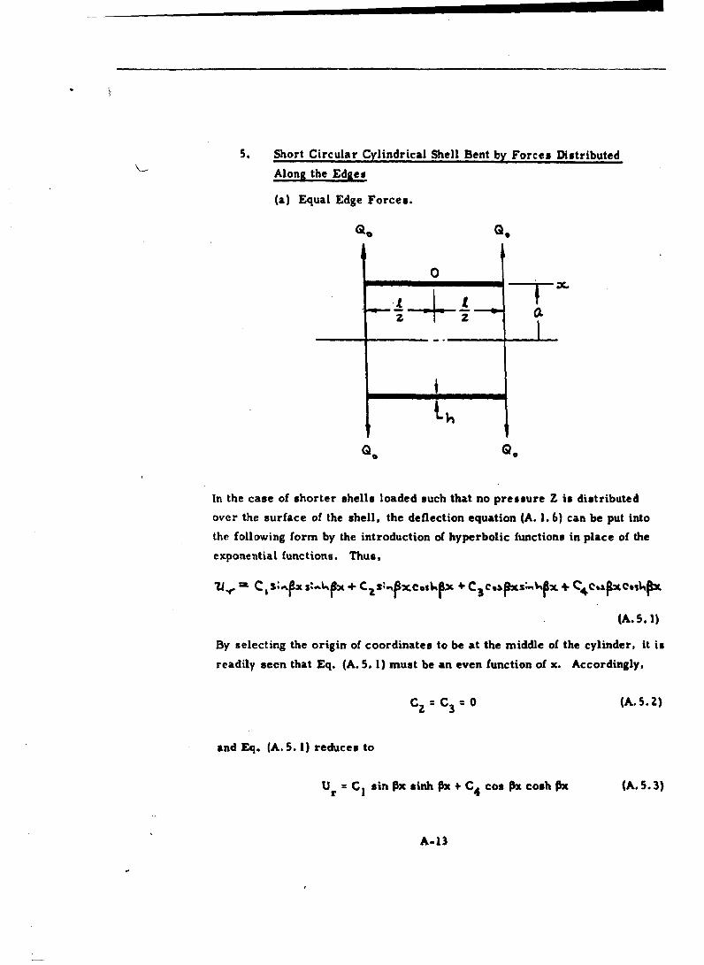
5. Short Circular Cylindrical Shell Bent by Forces Distributed
Along the Edges
(a) Equal Edge Forces.
QO QO
0
in the case of shorter shells loaded such that no pressure Z is distributedover the surface of the shell, the deflection equation (A. 1. b) can be put into
the following form by the introduction of hyperbolic functions in place of the
exponential functions. Thus,
7J. - C~ X S.-IX+ X-%XO X + o 4;If x+C CAxois.
(A. 5.l1)
By selecting the origin of coordinates to be at the middle of the cylinder, it is
readily aeen that Eq. (A. 5. 1) must be an even function of x. Accordingly,
cC z=C3 = (A. 5. 2)
and Eq. (A. 5. 1) reduces to
U r = 1 CISin Ox inhOx + C4 Cos Px cosh Ox (A.S. 3)
A-13

The constants CI and C4 may now be determined from the conditions at the
loaded end x 1 1/2 which may be written
D A' u0 -0 (A.S. 4)
Performing the above operations, there are obtained
0 sin PIsin 1
S= 1(A. 5.5)C4 -ý-sinl+ sinh PI)
Equation (A. 5. 3) then becomes
2 z -- --;xS;%P + eo.¶-- C-SIX c.13%o-SUIAp2)
P 3
(A..46)
A. 14

The successive differentiations of Eq. (A. 5.6) are
ýA. .,7)
cli =. Q, _ __ _ _ __ _ ___I__ _ __ __a_ _ _
D -. 1,
P6o -Cos Y- + cos 14P
(A.S. 7)
The deflection and the slope at the loaded ends are therefore, respectively,
0 coshP1+CoUr 1 3 ~sin 01 +uinhp(x=*. ZP D(
~ r0 (Sinh P1 -sin
and the expressions for M x, MV Q and N 0become, respectively,
(cont.)
A-15
Me='--cw•'-L ~ , s4 .e ue,,L= 1 (A'. ,9
4Q-z . Pa 11;J IS4,13 + , or .• fttO CVj
P . 2 Iftiu.dp
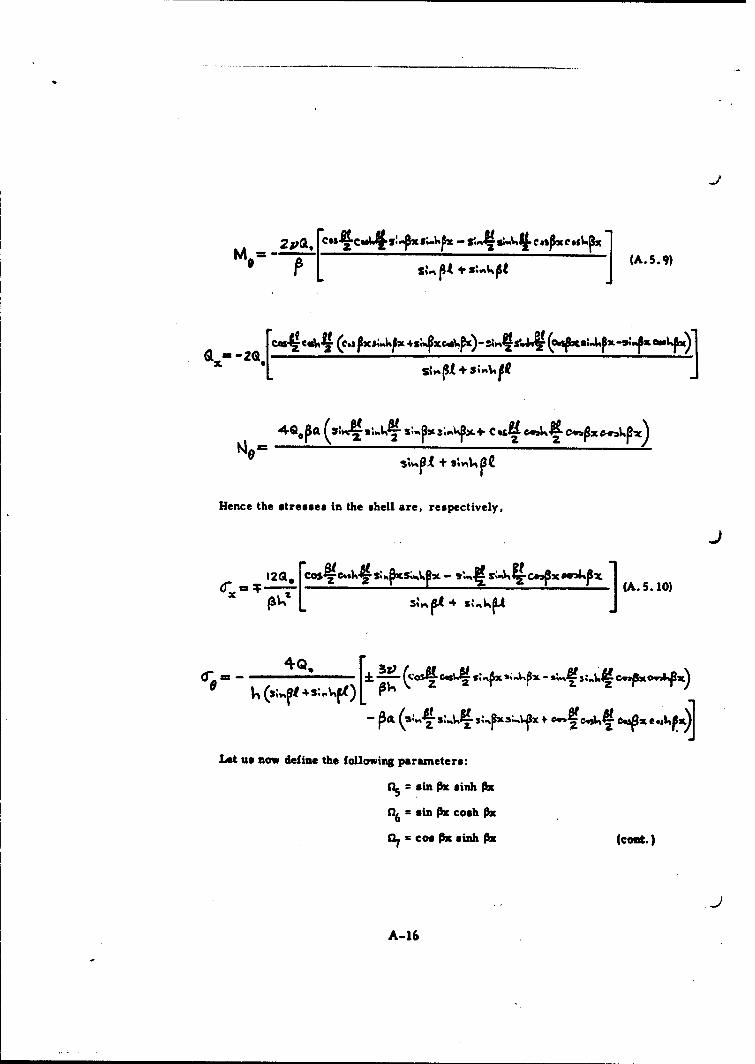
Hence the stresses in the shell are, respectively,
S (A.5.1o)
Ire z C-s%*P2 :.%P%
- ~ti :.ý xs...Sf caf e -516,.i~*)
Lot us now define the foUowing parameters:
sn = s in s Ox
n6 = sin Pz cosh O3
S= coo Px sinh Ox (coot.)
A-16
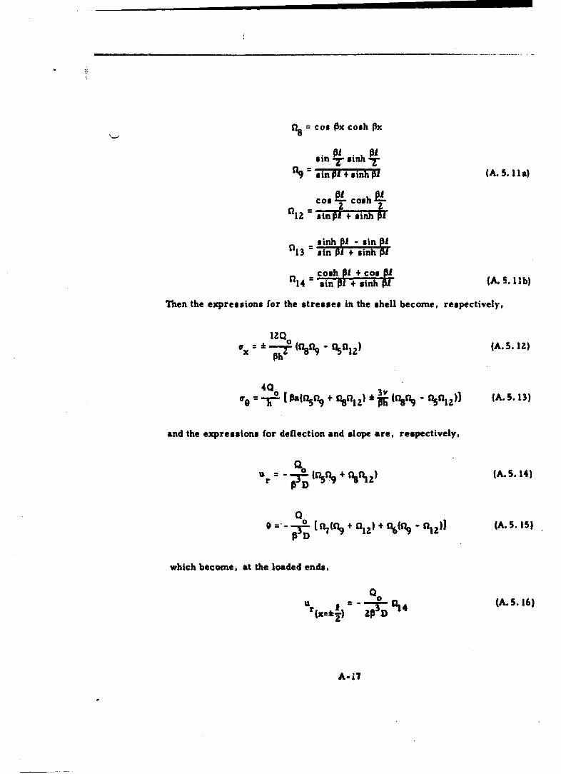
n8 = cos Ox cosh 3X
sin sin P1
'l3=sin P31 + sinh AlS.I acos • osh
o~e--y [ .(• + sinih ej -girt) P1 . 3
a13 sin P1 +sinh P1
Then the expressions for the stresses in the shell become, respectively,
lZQ
=* 011z (A.5.l1Z)
403
W 0-To [pauns,+as%"I)d W asn, -Tonl,)l IA.5.13)
and the expressions for deflection and slope are, respectively.
UrT IDA 11 "AdZ (A. 5. 14)
PD
which become, at the loaded ends.
u r I =4 (A. 5. 16)(x=*) ZP D
A-17

0
(b) Unequal Edge Forces
oQZ
T 0
In this case, the four constants of integration of Eq. (A. 5. 1) will be evaluated
from the following boundary conditions:
(o& .,- -D ,.. _o ,,..,
D- (A. 5. 18)
A-18

Specifically, they are
(A. 5.19)
These values of ci (i =1, 2. 3, 4) may now be substituted into Eq. (A. 5. 1)
to give
"=A s3. (QsQ2 +~~J
'2 +
(A. 5. 1)
A- 19

The successive differentiations of Eq. (A. 5. 20) are
2P D(,sM 4,f-s,.it) '"
@~ ~ ~~ ~~A S.- 2:,4 1)•• ""s,
",c--.N -zz~ - ,do '-*,-.-f,,
d..l
+ A- +
-A--

On the other hand, the deflection and the slope at the loaded end wherex = f will be
(A 5. 24)
o 4~qft.zuzi~ (A.S. 25)
The expressions for MX. Mo, QOx and Nd may now be easily obtained bysubstituting the expressions for ur, d2 u r/dx. and d3u r/dX3 fromEqs. (A. 5. 20) and (A. 5. 21) into Eq. (A. 1. 7). Of particular interest to
our study are the stresses in the shell. These are found to be
L.S
A-) c Oliz
A-21
aI,
+ (~a ".":"c'4s;,. • [ .(o"il "'"aI -,s9.tr o.,lI") t
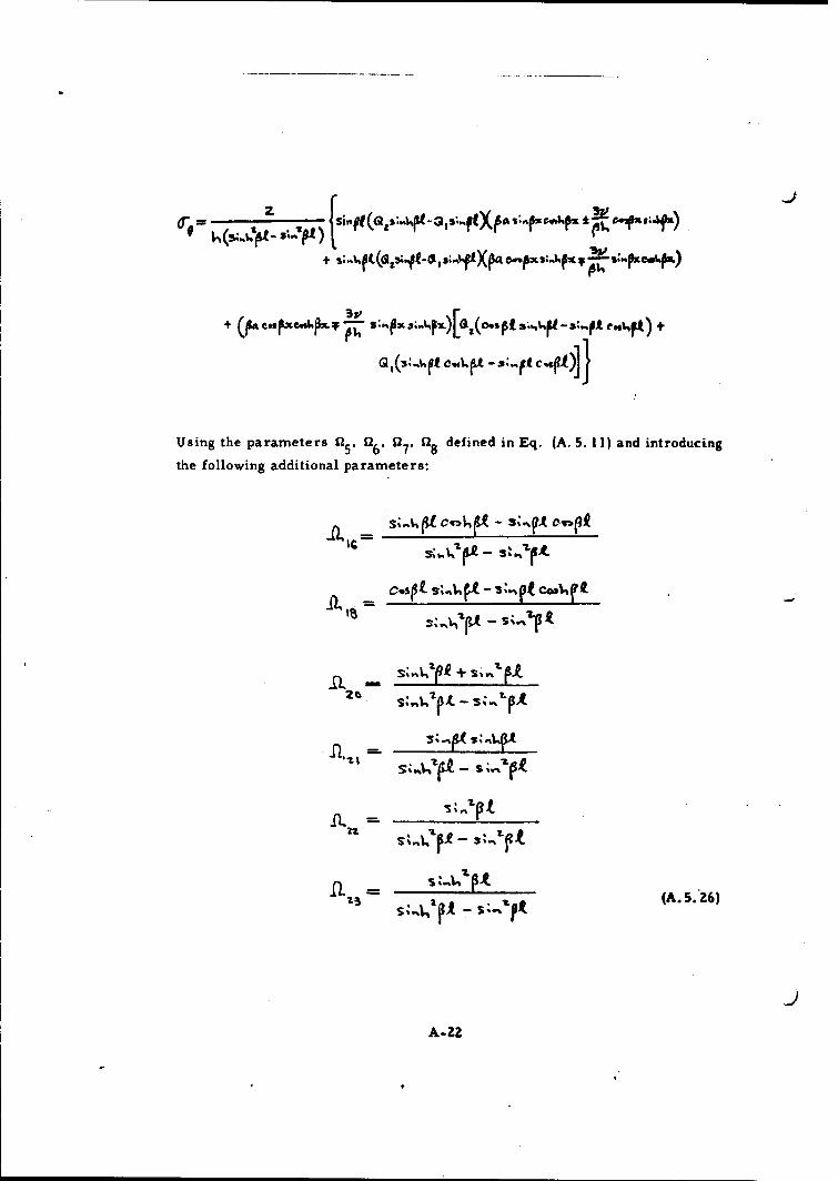
Using the parameters 152, "6' "7' "8 defined in Eq. (A. 5. 11) and introducing
the following additional parameters:
A-FZI
osot fr ~SZP 1Vtp
(A. 5.26
A-22

We find the expressions for the stresses in the shell to be
, (A.5.3 . )
The expressions for deflection and slope are correspondingly
+ (A.S.,30)
and at the loaded ends, the deflections and slopes become
- -g ()(A. S.•3,1)
A-23

-.J
"2 "z+ IB ) (A.S.3z)
0 =(Z" g ., .. - .l,•,Q 1 ) (A.S.33)
6. Short Circular Cylindrical Shell Bent by Moments Distributed
Along the Edges
(a) Equal Edge Moments
M.
Again, in this case, Eq. (A. 5. 3) is applicable. The constants cI and c 4
may be determined from the following boundary conditions:
= ,..• = M
-('"-• = ,•(...6.l,
.A
A-24

Specifically, they are
cI= - , ,-,,• ÷,e 2
C4m - ( z:,;,) (A.6.z)
The deflection equation for the middle surface of the shell is then
•'=,(,••,pl÷'"H)(A. 6. 3)
The successive differentiations of Eq. (A. 6. 3) are
- rn z,.(o.,s., cus-hl-,.fz,,'s o-e.ij :,-F.,ew•)
CAA V,( 4 +~4 OVC4 afCm4-x -( g4
- (A. 6. 4)
"( 5+

The deflection and slope at the loaded ends are now obtained by substituting
i 1/2 for x in the above equations. Specifically, they are
V(& 3%-1- - (A. 6. 5)
The stresses in the shell are, respectively,
4r. W.,
Using the parameters 115 , 6, 7' as, fa 13 defined in Eq. (A. 5. II), and
introducing the following additional parameters:
pi 4,, s o-,
AAZOL=II :,.ft4 S3.*j1-, (cont.)
A-26

" "5--- ,*0 -e4•t, (A. 6.7)
We find the stresses in the shell to be
I" .l,' ).R- (.Ll• L-.•)II (A. 6.8)
All (A (A. 6. 9)
together with the following expressions for deflectio-n and slope:
L4ZFjff l. ~ ,) Iy , •6A) (A.6. 10)
e=. - RIA 4 (A. 6. 11)
The corresponding expressionsfor deflection and slope at the loaded ends
* are then, respectively,
-L(..½ = - ..c •' fA.6.12)
A.-Z7

j
(b) Unequal Edge Moments
a.
0j
Here, because of the unsymmetrical loading, Eq. (A. S. 1) must be used,and the constants of integration will be determined from the following
boundary conditions:
(X•" 0
VA ) = -
Io (A.6. 14)
A-28

Specifically, they are
zpo•,= % M, •(iu•-P e"I s + , c.. i,-.'.r- ,(. cmt, f* * es E)
c.- zM s"•t :(lP - M,(s';"t 4s',*Lp•)
ZD ('C4:~t (A. 6. 15)
To recapitulate, the deflection Eq. (A. 5. 1) is
IM.a C, I 1"ft:6 4 CIL S,1FeAlqz C aCim?2s-,L ý%* Ce~spLeb.?xp
with successive derivatives of
S- ( cIfx 4 , S-X 9.L. •,X)- (,p•. sI-..puf)
A-Z9

"The deflection and the slope at the loaded end where x = 0 are then
N--r C+
2M~2~,~L ~ + (A. 6. 16)
(A. 6.17)
and the deflection and slope at the loaded end where x = I are
r . _ (A.6. 18)
4• L4 " •.:, a .•,ft -,,.R)J
(A.6.19)
A-30
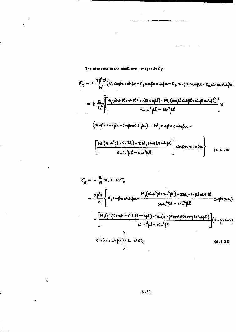
The stresses in the shell are, respectively,
Or- F ( tf 04%P C2 1.~ ".x 3; X-C 3 .. fLOl204.U. C4.
+ .4p ;1Pf cmb~t)- Mj(e*SPiS"PE f* +~~L
(- •,e.,Ib,•-... ., " cs•"•e~. -'i - ,
I- 1 S i-- • it-l s,~r,_.
(A. 6.A0)
A-31

Using the parameters n, a 6' a7' 18 9 defined in Eq. (A. 5. 11), and 020,
D21 defined in Eq. (A. 5. 26) and introducing the following additional
parameters:
.a. - .,kot cS t.4. t taui
I,• -- (A. 6. 2Z)
We find the stresses in the shell to be
± (Mf~~fl.)fc4. 7 .(M.AzzZhitA9)Afi4-M f1 8 (A. 6. 23)
all
The expression for the deflection and slope then becomes
LVI (A. 6. 25)
- I, (A.+-,a,)] (A. 6.26)
A-32
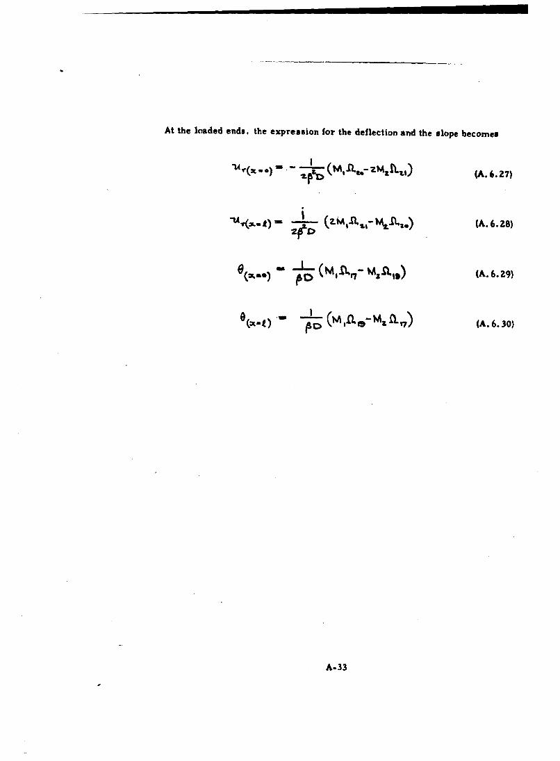
At the loaded ends, the expression for the deflection and the slope becomes
e(-..t - ((A,...- z .. ,) (A.6. z7)
(M( 0) - :v (A. 6.30)
A-33

B. JUNCTURE SHEAR FORCES AND BENDING MOMENTS
I. Two Long Cylindrical Shells of Unequal Thicknesses
-F t t t f tt tt tT~t*~- "t
zo.
Fig. B. 1. 1. Two Long Circular Cylindrical Shells ofUnequal Thickness Under Internal Pressure
Under the action of internal pressure, the circular cylindrical shells will
extend radially, each by a different amount due to the different thicknesses.
However, in the actual vessel, the two cylinders are kept together and strain
compatibility at the junction indicates that there must act shearing forces Q0
and bending moments M uniformly distributed along the circumference and
of such magnitudes as to eliminate this continuity.
Q.
Fig. B. 1. 2. Forces and Moments at the Junction of the two LongUnequal Thickness Circular Cylindrical Shells
A
A-34

The stresses produced by these forces and moments are called discontinuity
stresses. This condition is illustrated in Figure B. 1.2.
To determine the magnitudes of 00 and Mo, it is necessary to have the
appropriate formulas for long circular cylindrical shells bent by forces and
moments distributed along the shell edges. These formulas are readily
available in many texts on shells. Thus, from Reference 4, the deflection
and rotation produced by the loads p, Q0 and M are:
(a) For Cylinder No. 1:
g;= (Bl2
(b) For Cylinder No. 2:
M t (B..,3)
01.- -QzeIme) (B.1. 4)
where 6 = radial deflection of middle surface at junction, positive outward,
inch.
6' = rotation of middle surface at junction, positive as shown in Fig.
B. 1.3.
A-35

4 Ehi 3( - v2) 2_ - 22 (i 1,2)
I 1
Eh.3
D. 121- x (i= 1,Z) (B.I. 5)D 12(1 -V•-
a = mean radius of curvature of the circular cylinders;
p = internal pressure, psi;
E = modulus of elasticity, psi;
v = Poisson's ratio
Q0 = uniformly distributed circumferential shearing force at the
junction, lb per inch;
M = uniformly distributed circumferential bending moment at the
junction, lb per inch;
C9
V 0-SLme M.([o
Fig. B. 1. 3 - Signs Convention for Middle Surface RadialDeflection and Rotation at Junction
For strain compatibility, we must have
6 (for Cylinder No. 1) = 6 (for Cylinder No. 2)
61. (for Cylinder No. 1) = 6' (for Cylinder No. Z) (B. 1.6)
A-36

Hence
*EV 1 2
I (zp,•-,t.) =.--(-K.
z12o
from which
IG 0. 1Epl t. 7.)
••I "\I)
These formulas for Qo and M0 may be simplified to the following dimension-
less form:
) (B. 1. 10)
where c = thickness ratio hl/h,.
A-37
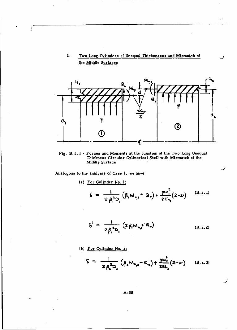
2. Two Long Cylinders of Unequal Thicknesses and Mismatch of
the Middle Surfaces
I7 ,OLI
Fig. B. 2. 1 - Forces and Moments at the Junction of the Two Long UnequalThickness Circular Cylindrical Shell with Mismatch of theMiddle Surface
JAnalogous to the analysis of Case I, we have
(a) For Cylinder No. 1:
( 2. 1)-.)
-2 OolI
(B.2.2)
(b) For Cylinder No. 2:
2 P.; 04 L
A-38
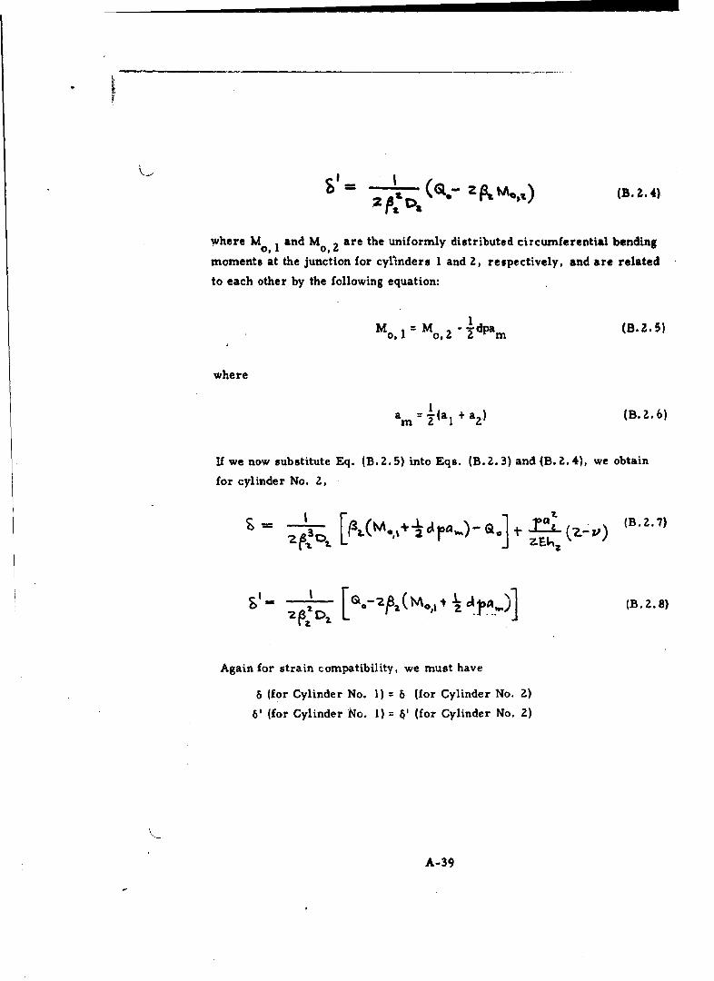
S -(Q- z3map%) (B. Z.4)"=".2 t -
where M, 1 and Mo0 2 are the uniformly distributed circumferential bending
moments at the junction for cylinders I and 2, respectively, and are related
to each other by the following equation:
I
M M 2 " 2"dpam (B. 2.5)
where
1
am =(aI + a.) (B..b6)
If we now substitute Eq. (B. 2.5) into Eqs. (B. 2.3) and (B. Z. 4), we obtain
for cylinder No. 2,
Again for strain compatibility, we must have
6 (for Cylinder No. 1) = 6 (for Cylinder No. 2)
6' (for Cylinder No. 1) = 6' (for Cylinder No. 2)
A-39
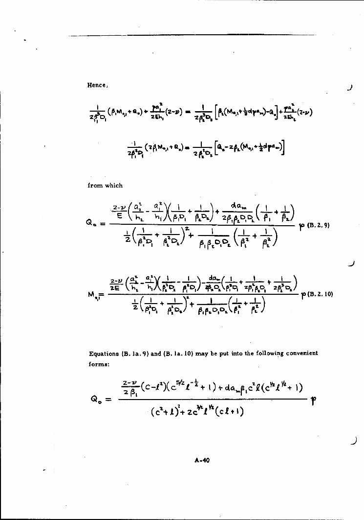
Hence,
from which
o 2L •,-,A,,+ )+ =,,><,-n7.(E 0)-+/
2-V ( V +__ , ,,.._Te-- Q(4.-..2)•10) ,-,- 0kr -)
Equations (B. Ia. 9) and (B. Ia. 10) may be put into the following convenient
forms:
- -,C-- + 4 C (C +
A-40

(C, ,,../t Cz r-V 7
Mo1,,= M, + C1 C1 V^.
where c a thickness ratio hi/hz
I.= middle surface radius ratio aI/a2
Observe that the above equations are developed for al< a2' If aI >a2, then
d becomes negative, and the components of shear and bending moment due to
the mismatch alone of the middle surfaces change in direction.
For thin shells, a/h is large and I can be taken as unity for all practical
purposes. The equations for Q00 Mo 1 then simplify to
-' .-I )( c5÷ + + C1A.P I e'(•V" + 1)2312(c1I)a,-C ''•Tt 1)
(cZ'(C T) 22"(c I)4 pll (C - + 2C ) (C- + 1)'
)
A-41

3. Long Circular Cylinder with Circumferential Ring Stiffeners
Fig. B. 3. 1 - Long Circular Cylinder with Circumferential RingStiffeners under Internal Pressure
Basic Assumptions: (a) The ring stiffener spacing is such that the influence
of one does not extend to the next.
(b) The term "a" will be taken to be the outside of the
shell instead of mean radius. For shells with a
large radius to thickness ratio, the effect is negligible.
V4 M.
N,
Qt Q.
Fig. B. 3.2 - Forces and Moments at the Junction of the CircularCylindrical Shell and the Circumferential Ring Stiffener U
A-42

Boundary Conditions: (a) The radial deflections of the shell and ring are
equal at the junction.
(b) The slope of the shell adjacent to ring it zero.
Analysis: The deflection of the long circular cylindrical shell at the junction
produced by the loads p, Q0 and M is, from Reference 4,
2
-= (Mo0 -0 + - v) (B.3. l)
The radial displacement of the circumferential ring stiffener under the action
of the forces 2Q and p may be readily obtained from the plane stress solution
of a thick-walled cylinder under the action of internal pressure. Specifically,
at the ring-shell interface,
a(ZO + pc)b' + a2 +
\o b--a /
In accordance with boundary condition (a), we can immediately write
2 a(Z 0 0+pc) /b 2 +a' + 33)
2P 3 D -00a I÷P C -
The slope of the circular cylindrical shell adjacent to the ring produced by
the forces p, Q and M is, from Reference 4,o o
1
6' = -(2PMo- Oo) (B.3.4)ZPZD
This, in accordance with boundary condition (b) is zero. Hence
Q 0= ZPM 0(B.3. 5)
A-43

Equation (B. 3. 5) may now be substituted directly into Eq, (B. 3, 3) to give an
explicit expression for the circumferential bending moment M . Specifically,o
1> L21. -It--•'•"•71(B. 3. 6)
+a-
Q =ZAM (B. 3.7ý
4. Long Circular Cylindrical Shell with Many Equidistant
Circumferential Ring Stiffeners
H(,.,•t\S L• j- h'• C ('rye)
LLL1 L2W Ct
Fig. B. 4. 1 - Long Circular Cylindrical Shell with Many EquidistantRing Stiffeners under Internal Pressure
Basic Assumptions: (a) The ring stiffener spacing is such that mutual
influence becomes important.
(b) The rings are all of the same size and design.
A
A-44

(c) The term "a" will be taken to be the outside of the
shell instead of mean radius. For shells with alarge radius to thickness ratio, the effect is
negligible.
Boundary Conditions: (a) The radial deflections of the shell and ring are
equal at the junction.
(b) The slope of the shell adjacent to the ring is zero.
Analysis: As a consequence of the proximity of the ring stiffeners, the long
cylinder must be treated as composed of a number of short
cylinders, each of which has a length i. The discontinuity forces
and moments at the junction of the short circular cylindrical shell
and the circumferential ring stiffener may be taken to be identical
to those shown in Fig. B. 3. Z. In this case, however, the deflec-
tion of the short circular cylindrical shell at the junction produced
by the forces p, Q and M is, from Reference 4,
+.i. a "' )~4%~f +u 311)
The radial displacement of the circumferential ring stiffener has been
calculated previously and is
A-45

In accordance with boundary condition (a), we must have
-QAg Z~~'CO51%F14 :::S )+ 2VASOIO( S.: t. ;ý'p
(2 6.+pC)a (6 t a +
(B. 4. 1)
The slope of the short circular cylindrical shell adjacent to the ring produced
by the forces p, Q and M may also be obtained from Reference 4. Specifi-
cally, it is
2 (9A s S;j3a ( 1CO54 -
This, according to boundary condition (b) should be zero. Hence
GO= !L) VA (B..4..i)
If we now substitute Eq. (B. 4. 2) into Eq. (B. 4. 1), an explicit solution for the
circumferential bending moment M will be obtained. Indeed,
-(B. 4. 3)
A-46

where sinh O sin 01f13 s'inh P1! + sirn 1
cosh el + Cos B114 sinh P1 + sin Im (B.4.4)
cosh el - cos P11't5 :sinh P1 - sin.pi!
Using the above notation, we find 0 0 20n 5Mo (B.4.5)
5. Long Circular Cylindrical Shell with a Flat Head Closure
t4. tWA.
SIfI. o
I,~
Fig. B. 5. 1 - Long Circular Cylindrical Shell with a Flat Head Closureunder Internal Pressure. The forces and moments areshown in the positive sense above.
The following compatibility equations between cylinder and head are obtained
from Reference 5, and are modified to conform to the notations of Fig. B. 5. 1.
A-47

M Qo M Q0 0b + -- b b + b +b (B.05.2-~ 4 5 ~ 1 Tp-a 2 3 ~JP
4pa Tp, 4pa
where
6al V'b 6 (1- v)-Iaz h1 h 2
a =2 (l - v) b 2 3(1 - v)
2P7-ah,
3a 3(l - v)
2 16p ZhIh 2
S =-z 2 h22 b = I,•- )25 vi- 5 -Zj
h 2 3(1 - vz) (B.5.3)6~ a h1
Solution of Eqs. (B. 5. 1) and (B.5. 2) yield the following expressions for 0o
and Mo. Specifically, they are:
M = 4pa2 [(a 4 -a 3) (b. -b 5 ) + b3 (a. - a6 ) 10 1(al- as) (b2. be). (az. a6) (bl. b4 ) j (54)
Q =2pa[ (a3 -a 4)(bl -b 4)+b 3(a5 -a 1,)0 .2 (a,-a 5 )(bz-b 5 ) -(a 2 -a 6 )(b, -b 4 ) (355)
A-48

6. Short Circular Cylindrical Shell with Equal Thickness Flat
Head Closures
Fig. B. 6. 1 - Short Circular Cylindrical Shell with Equal ThicknessFlat Head Closures under Internal Pressure
The signs convention and notations of Fig. B. 6. 1 will be used in the present
analysis. For the case of a short cylindrical shell, the radial displacement
(positive inward) 6, and the rotation -61 at the junction due to the forces p,
Q and M 0 are, respectively,
I___ _- 4M9B3 CLL Q C%3
A-49

The dimensionless form of these two equations may be chosen to be
= a a + ~ :(B. 6. 1)
_ _ _ _ _6 4. (B .6 . Z2)
where
a - ---
44
6 =- , ) (B.6.3)
These "influence numbers" may be substituted in lieu of the influence
numbers a 4 , a 5 , a 6 , b4 and b 5 for the long cylindrical shell in Eqs. (B. 5.4)
and (B. 5. 5) to give the expressions for the shear force and bending moment at
the junction where the flat heads abutt the cylindrical shell, respectively.
A-50
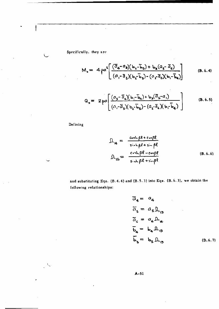
Specifically, they are
[e=- • ý (4-)' ) +----(a'-• 1 B. 64)
= 4r (c~~)(bj (~1~~G)6,-4)J
o= i (0 3 6- 54(6,- 64)+ 63(' ) B..6.5)
Defining
C(R -eq3 (B. 6. 6)
and substituting Eqs. (B.4.4) and (B. 5. 3) into Eqs. (B. 6.3), we obtain the
following relationships:
C14 = 4
OG 0
6 6 4.
6' S 65 •(B. 6.7)
A-51

Equations (B.6. 7) express the correspondence of the influence numbers
between the long and short circular cylindrical shells. Substitution of these
relationships into Eqs. (B. 6.4) and (B. 6. 5) yields
M*'- ~ 4p~[ (04- 03)( 6a- 65a ,) + 65( a 2- ar 4
QL= 2 [ (s 4 (6r 4'a 6(aa ' (B. 6. 9)(0 [ - ca11%X 627 65il,3) - (a2- a6"(6,-6-Qv)
7. Short Circular Cylindrical Shell with Unequal Thickness
Flat Head Closures
M, Mt AI
~~4.
Flat Head Closures Under Internal Pressure
A-52

For the short cylindrical slt Il, the radial (Iisplacvnent (positive inwa rd) b,
and the rotation -8' at the junction wherv x 0 dlt to the fi-rc.s p. Q O,
M1, and M are, ;espectivelv,M~. 2
+ -z-M1 (S,;-,. Q , •..') - 2•M,,.. I.;,.,Q - e (z-z.,) B71
- =(,.4•Z•- a, .. lp-. ZEA)
- - (s ,•,tQ .. ,I) * vz
1> (B..~ 7.
For the junction x = I, the radial displacement and the rotation are,
respectively,
+. .;.t t- M •.(sM•' -) f ..s Iz -.,) (B. 7. 3)
+
(B. 7. 4)
A-53
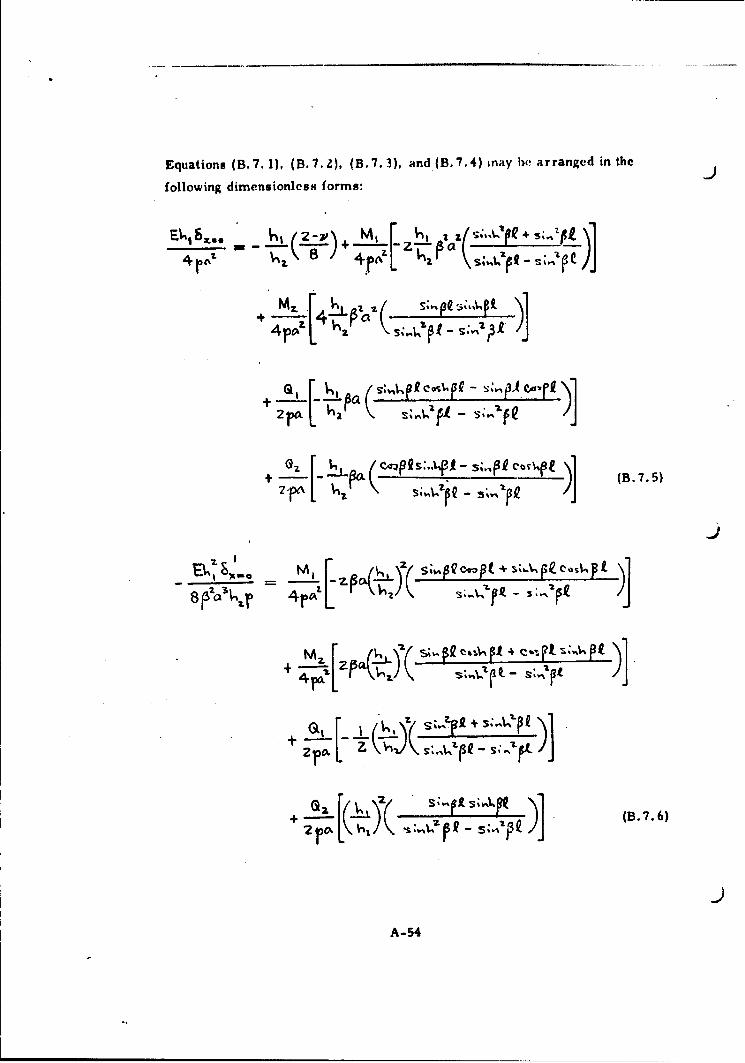
Equations (B. 7. 1), (B. 7. ), (B. 7. 3). and (B. 7. 4) inay he a rranged in theJ
following diniensionlcst; forms:
IA2-\ , it 1 If S.p 3,'Ip1 \______~S; IF--, -- z ~
+ ±!4 Lo~PS~3~(B. 7.5)
+ M z(.'p ' s4~
(B. 7. 6)
A-54
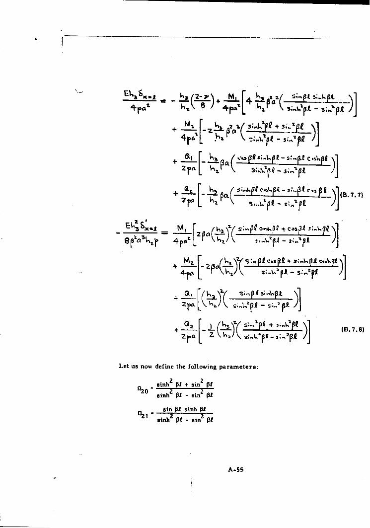
'•,oU =- -,k , i L__1 ,ep-•.#)
•J)'A •4 .- -- -''7-+J
*1* " . c , : .•p -, . i. t3 /14rl
+2 :sih Ij -sin • )JB 77
+ ck (B. 7. 7)
Let us now define the followi ng parameters:
sinh2 zAl + sin 2 of22 inh2 zAl - sin2 zP1
sin PI sinh Of
sinh2 11 - sin2 PI
A-55
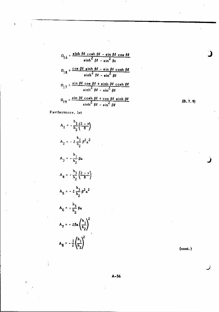
sinh Of cosh Of - sin O1 coo 131"sinh z3P - sin2 PI
cos PI sinh P1I- sin 01 cosh 1I18 sinh2 131 - sin2 Of
sin Of cos 13 + sinh 1O1 cosh 13O1 7 -- sinh2 131 - sin2 1P1
sin 13I cosh P1 + cos O1 sinh 11 (B.7.9)19 sinh2 131 -sin 2 1(7
Furthermore, let
h1
h
h3
A3 h3 Pa2
h3A6 = - P a
6 h a
A7 = -2pa
152A s h" 1 22) (cont.
A-56
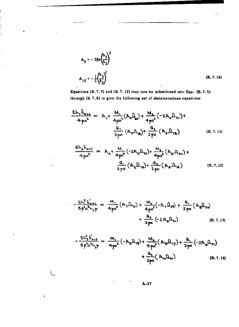
1 N(N2.) (B.7.10)
Equations (B. 7.9) and (B. 7. 10) may now be substituted into Eqs. (B. 7.5)
through (B. 7.8) to give the following set of dimensionless equations-
- L4 0/ 4 ra"
IPNA6+ -L(B
111" zra
-~ ~ 4 4, ' = •-• (-ZA.,4¢ + '-a,., + 2••• ,
4 4r,ý+ , (B. 7. t1 Z
+ (Bs. 7. 3)4
A-57
A-57

From Reference 5, we find the following dimensionless equations for the
heads:
4c 4 It t AI Is(B.7. 15)
- k " I- + (8.7.16)
• 3•-- - - (B.7.17)
3~Zm ~ % *(B. 7. 18)
where
= 2(0-v)
~= -sO-•,)
Set (IV)
z C i-t (cont.)
A-58
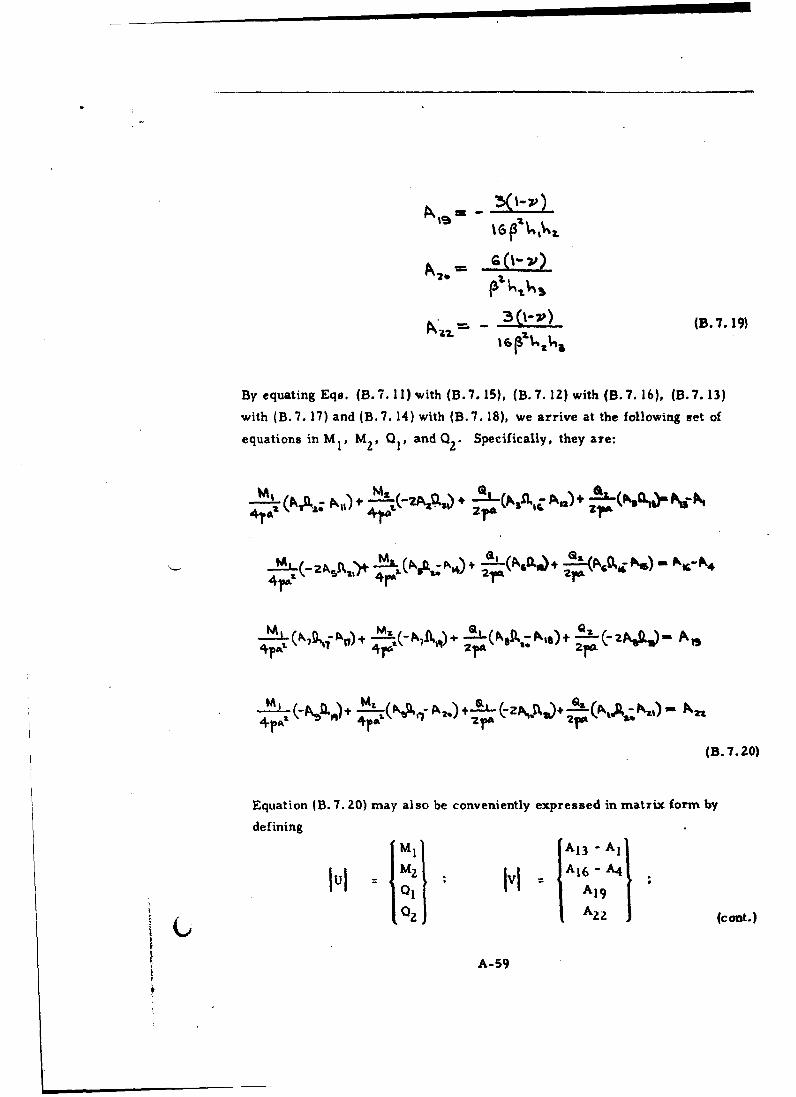
3 (--) (. 7. 19)
By equating Eqs. (B.7.11) with (B.7.15), (B.7. 12) with (B. 7. 16), (B. 7.13)
with (B.7. 17) and (B.7. 14) with (B.7. 18), we arrive at the following set of
equations in M V M2 , Q V and Q2 " Specifically, they are:
4
2'
(B. 7.20)
E~quation (B. 7. 20) may also be conveniently expressed in matrix form by
defining
,Qf v AN) J +cot.)1IzJ IV
A-59

+'1
4 pO= 4 4-ra, 2p a 2rA
________7 p%715 N Z; Nis ___At__4
,4pe, .. 4r2 2p- 2 rc.
L 4TP z 4rct z 2'1a 21(B. 7.21)
Then,
and ,.l
lul = wf'Ivl (B. 7.22)
8. Long Circular Cylindrical Shell with an Ellipsoidal Head Closure
•t.
I ._. _. _ __
Fig. B. 8. 1 - Forces and Moments at the Junction of the Long CircularCylindrical Shell and the Ellipsoidal Head Closure underInternal Pressure
A-60

_ _ _ _ IIII III IIIIIII
+Q°.
Fig. B. 8. 2 Signs Convention for Middle Surface Radial Deflectionand Rotation at the Junction
The radial deflection and the rotation of the long circular cylindrical shell atthe junction produced by the loads p, Q., and M are, respectively
((B. 8.2)z PC". (zEA, .)(.82
whereE1,1
(B. .3)
A-61

The radial deflection and the rotation of the ellipsoidal head at thc junction
produced by the loads p, Q0o and M° are obtained from Reference 6, and are,
respectively,
3 ~ ~~~ ~ 9 CM)+2- V) (B. 8.4)
(B.8. 5)
where
p.,. .(Bs.86)1z (I 22-
For strain compatibility, we must have
6 cC e
6c 6e (B.8.7)
Hence,
- D- 2 E Vz ( -
Z&(Z_
P2C DCzf3,.,Q.) - Co- .. )
A-62
from which
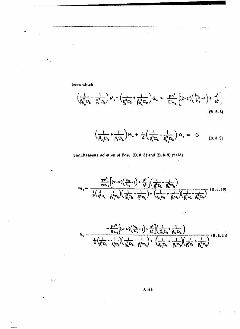
(B. 8.8)
Simultaneous solution of Eqs. (B. 8. 8) and (B. 8.9) yields
•" 2E U, -- I .L_ _ _ . tL A:t:,,- t (B. 8. 10)
•,--•c, .P., Pc .• - .•-''4 (B.8. 11)
A-63
I
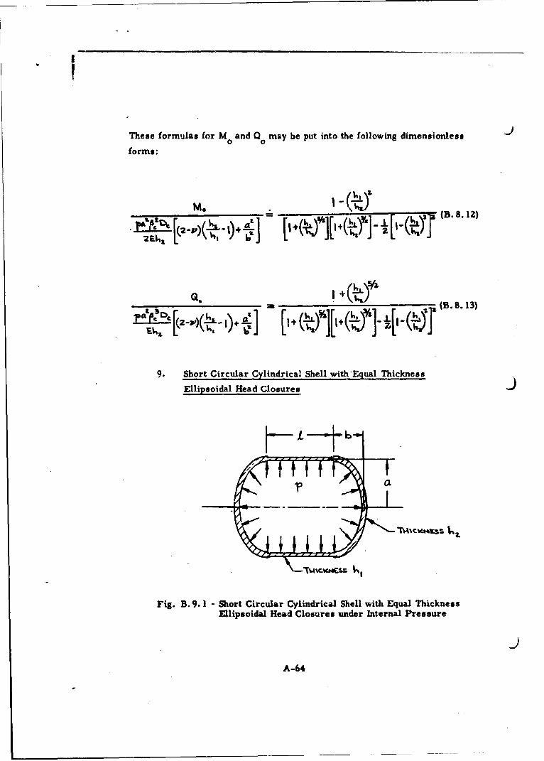
These formulas for M and Q0 may be put into the following dimensionless
forms:
MI. ___ +__,_ ____1~~~A2~~~ L(l(k4I B8 2
-- (B. S. 13)
9. Short Circular Cylindrical Shell with'Equal Thickness
Ellipsoidal Head Closures
6
Fig. B. 9. 1 - Short Circular Cylindrical Shell with Equal ThicknessEllipsoidal Head Closures under Internal Pressure
A-64

The signs convention and notations of Fig. B. 8. Z will be used in the present
analysis. For the short circular cylindrical shell, the dimensionless forms
of the equations for radial displacement 6c and the rotation 6' at the junction
due to the forces p. Q0,, and M0 are given by Eqs. (B. 6. 1) and (B.6.2),
respectively. These are listed in the following forms:
E62 C t M . &( %3t o a(S.9.0
• -- "+ (B. 9. 2)
Ct ,11, 4 * -.,2.a ra•• is
where a4 , a5,. a 6, b4 and b5 are as defined in Eq. (B. 5.3); 0 13 by Eq. (B.4.4)
and n 14 and 1l1 5 by Eq. (B. 6.6).
For the ellipsoidal head closure, the radial displacement 6 e and the rotation
6' at the junction due to tlhe forces p, Qo, and M are given by Eqs. (B. 8.4)e 0
and (B. 8. 5). These two equations may be written in the following dimension-
less forms:
-- Ž• a + a,+ a, (B. 9.3)
1 - 6 (B. 9.4)
where
hz603£2, -
J= 'V) (cont.)
A-65

I
J
61 2%
(B.9.5)
In accordance with the strain compatibility equations (B. 8.7), we have the
following equalities:
4 1'34 6, +4 2
M__. 6A,+ (R6_. 6 M+ _ .4p" =°b•'= P• • + --rp2 -
from which
.(,• �,•.CA - •3)(.6.,- (6 ,-,,,a1( ,-,
6A - 66Ats) (B. 9.7)
A-66

10. Shrt Circular Cylindric-al Shell with Uncqual Thickness
Ellipsoidall Head Closures
)AM, M, NO
x= a
Fig. B. 10. 1 - Short Circular Cylindrical Shell with Unequal ThicknessEllipsoidal Head Closures under Internal Pressure
The signs convention of Fig. B. 8. 2 will be adhered to in this analysis. For
the short circular cylindrical shell, the radial displacements and rotations
at the junctions where x = 0 and x = 1, respectively, due to'the forces p, Q1 ,
a2' Mi. and MZ are given by Eqs. (B.7. 11) through (B.7. 14) in dimensionless
forms and will not be repeated here.
For the ellipsoidal heads, the corresponding dimensionless forms of the
radial displacements and rotations are:
-A~~+-~%l. 1-(B. 10. 1)
A-67

- |
+\7 s - (B. 10. 3)
Li: sn M( B. 10.4)
where
All 2a
A,
ok
A13 = 2= -
,T- I
Ale 5TI, A 2 ,
4 , _ £1., = ___-_,_Pcz~
a I
4 - X 3 -3 3(1 -,V)4a Z D.5 C " (cant.)
A-68

3_ _ (B. 10.5)S=z
Equating now Eqs. (B.7. 11) with (B. 10. 1), (B.7. 12) with (B. 10. 2), (B. 7.13)
with (B. 10.3), and (B.?. 14) with (B. 10.4) in accordance with the strain com-
patibility equations (B. 8.7), we arrive at the following set of equations in M,
M2 , 0O, and Q2 . Specifically, they are:
Let us now define the following matrices:
41-# 0 J
(cont.)
A-69

-2A.&D.Qz NA.t; PN14 NgI A1011- NSt
"[W] 4"1= 2=A 21r
P,71;.f-A7 _~i NAZA1 ZN_____
- Z,,°",f),1r 7is P4. (B. 10. 6)
+ra% 2ro
Then the four simultaneous equations listed above may be written in the form
[w] lul =IvI
from which
lul = [wJ ' vI (B.10o.7)
The coefficients Al through A10 in the above equations are defined in
Eq. (B. 7. 10) where it is understood that P PC. The functions f)2 through
119 are identically defined in Eq. (B. 7.9).
A-70
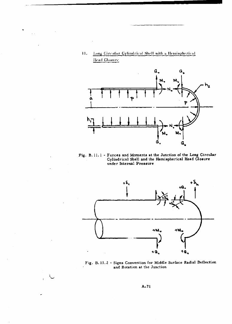
11, l, ,iig (irt',olir C_ ylincIri(';! Shell with a lihtIini pherit-I
"lit.&(I "i osti""
M. M.
Fig. B. 11. 1 - Forces and Moments at the Junction of the Long CircularCylindrical Shell and the Hemispherical Head Closureunder Internal Pressure
S+4.
Fig. B. 11. 2 - Signs Convention for Middle Surface Radial Deflectionand Rotation at the Junction
A-71

The discontinuity forces Q and , h t h
circular cylindrical shell and the hemispherical head closure under the
action of internal pressture can be readily obtained from Eqs. (B. 8. IZ) and
(B. 8. 13) developed for the case with the ellipsoidal head configuration; it
being necessary to replace the quantity a 2 /b 2 by unity. In so doing, we find
(B. 11.1)
(B. l1.2)
12. Short Circular Cylindrical Shell with Equal Thickness
Hemispherical Head Closures
Fig. B. 12. 1 - Short Circular Cylindrical Shell with Equal Thickness
Hemispherical Head Closures under Internal Pressure
A-72

K) jThe formulas dvcvlopcd for the cast, (if the short circular cylindrical shell
with equal thickncss ellipsoidal head closures are readily adaptable to the
present configu.ration by substituting unity in place of the quantity aZ/bZ.
For example, the quantity a 3 in Eq. (B. 9.6) for the bending moment Mo and
in Eq. (B.9.7) for the shear force o must now be replaced by
I
a3 I (B. 12.1)
13. Short Circular Cylindrical Shell with Unequal Thickness
Hemispherical Head Closures
asQz QI
• ~~t~l! t z I tV44
Fig. B. 13. L - Short Circular Cylindrical Shell with Unequal ThicknessHemispherical Head Closures under Internal Pressure
Formulas (B. 10. 6) and (B. 10.7) for the determination of the bending moments
M and M2, and the shear forces 1 and Q2 developed for the case of a short
circular cylindrical shell with unequal thickness ellipsoidal head closures are
also applicable to the present configuration with the exception that the quanti-
ties AI 3 and A1 6 defined in Eq. (B. 10.5) must now be replaced by
A1 3 At 6 = -A(1-v) (B. 13. 1)
A-73

I
14. L.ong Circ.lar Cyliid rih'al Shell with a Conical head Cl ouir.
QQ.
Fig. B. 14. 1 -Forces and Moments at the Junction of the Long CircularCylindrical Shell and the Conical Head Closure underInternal Pressure
C.o
144. OM.
t.
Fig. B. 14. Z - Signs Convention for Middle Surface Radial Deflection
and Rotation at the Junction
A-74

The radial deflection and the rotation of the long circular cylindrical shell at
the junction produced by the loads p, o, and M in accordance with the signs
convention of Fig. B.14.2 are, respectively,
(, =- . Q.) - (2-V) (B. 14. 1l
' • (2p•M.÷ +.2f= l~(B. 14. 2)
wnfere
3.. if (B. 14.3)
The dimensionless forms of Eqs. (B. 14. 1) and (B. 14.2) may be chosen to be
-- a.'l a4 +a; (B. 14.4)
IL
C. - 6 (B. 14.S)
A-75

where
a,=
a - 2 , CQ )
For the conical head, the corresponding dimensionless forms are:
4. -j , +7- ,• 9 + C1-3 (B. 14.7)
The quantities al, a2 , a 3 , bi, b2 , and b3 are dimensionless "influence
numbers" for the conical head and can be obtained from either References 2
or 3. In the notations of Fig. B. 14. 1 and the signs convention of Fig. B. 14.2,
these influence numbers become
-ýs iu-A
(cont.)
A-76

a-- " A \:Z.
612Ch ac
6 2 -
6S re0 V CSC (+6 A&-&*t Seca,- seree (B. 14. 9)
where
C Ao Cb*sec. A÷(B. 14. 10)
ror strain compatibility, we must have
c co
51 1 3' (B. 14.11)c co
A-77

Hcnc,•
4 Qoý . t-5 -&1* -r q= i 341 *
M. Q4+•
4rAA 2L-
J b4 ...61+ .--6S -l, 4 63 *6
2 ra (B. 14.13)
from which
Mi. "-4r.Az f(Q4 ) .( •.,- .1 (ai. (B.1. 14.14)
*=2 j,c F .6 (,a,+A 4 ,) +(OS+ Ct)( 6 4 :.. 6, 1B 4 5L (a,+a,)(b,-•). (1b,-,)(a,* 1• ,.4.15)
The Bessel-Kelvin functions ber, bei, ker, kei, and their first derivativeshave been extensively tabulated by Lowell (Ref. 7). Higher order Bessel-Kelvin functions are related to the aforementioned functions by the followingrecurrent formulas (Ref. 8):
I (- •, 6" (cont.)
A-?8

-Mr
6e;,+, AC;
bev, , = i i i IeI i+ 6e; I
'i-
Using these recurrent formulas, we find that the Bessel-Kelvin functions of
order two are related to those of order zero by the following expressions:
6 Z
6- + - ' (B. 14. 17)
A-79

15. Short Circiltar Cylindrical Sheli with Unequal Thickness Head
Closures of Ellipsoidal and Conical Shape
Fig. B. 15.1 -Short Circular Cylindrical Shell with Unequal ThicknessHead Closures of Ellipsoidal and Conical Shape underInternal Pressure
The signs convention of Figs. B. 8. 2 and B. 14. 2 will be adhered to in this
analysis. For the ellipsoidal head, the dimensionless forms of the radial
displacement and rotation have been-derived earlier,- and are:
- - Trtt Nil. t (B. 15.l1)
B 3 (B.15. ")
A-8O
-i I ! !Mz M

where
IDI~ --- 9zPCa
4
For the short circ-ular cylindrical shell, the dimensionless forms of the radial
displacements and rotations at x = 0 and x = I due to the forces p, 01 1 z'
MI , andM are, Er om Eqs. (B. 6. 11) through (B. 6. 14):
M2.
'I" (4.l.) + AL-_ (B 15
O-
A-81

+ 7,, (B. 15. 5)
A. el +
___= -2 ~ 4-•~ (z ~~PI)•= P
S. . SA-S=.Z±.(.
4?a
where
=I, L
P%z3
NS =- 2 h
~ (Cont.)
A-82

1 S.= P --(.')Z
m c.5 3I ll =S'Sp ' P A .
.e _ S,,%Af
Sý' S (B. 15. 8)
Finally, for the conical head, the dimensionless forms of the radial displace-ment and rotation at the base"of the cone due to the force; p, Qzo and M2 arerepresented by:
- (B. 15.9)
A-83
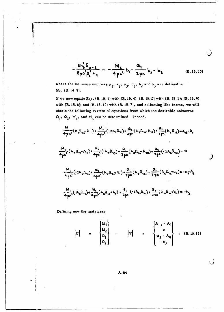
6- ~ 6 (B. 15.l10)
where the influence numbers a, aV, a3p b1 , b2 and b3 are defined in
Eq. (B. 14.9).
If we now equateEqs. (B. 15. 1) with (B. 15.4); (B. 15.2) with (B. 15. 5); (B. 15.9)
with (B. 15.6); and (B. 15. 10) with (B. 15. 7), and collecting like terms, we will
obtain the following system of equations from which the desirable unknowns
Q1 1 Q29 MI, and M2 can be determined. Indeed,
M,(A7 I (j.; A,.. + 7
+)
Defining now the matrices:
fMi A1 3 - Al'
S0 1lul 01ol IVI -a 3 -A 4 ;(B5.)
10Z I-b3j
A-84
-i
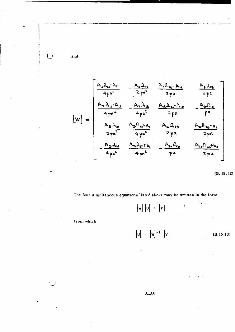
and
A-_ _ _ LA Z" •t - - iS.
A
•.
0. 1764jo PALG 2 1 ft
(B. 15. 12]
The four simultaneous equations listed above may be written in the form
[Wj lul = VIfrom which
Iul fw[" Ivj (B.15.13)
A-85
16. Short Circular Cylindrical Shell with Unequal Thickness Head
Closures (if Hemispherical and Conical Shape
If the ellipsoidal head of Fig. B. IS. 1 is replaced by a hemi-
spherica head of radius a and thickness h1 , the discontinuity forces Q1 0 Q2.
M and M associated with this new configuration can be readily calculated
by the formulas developed for Case 15. In this case, it is merely necessary
to replace the quantity A1 3 defined in Eq. (B. 15. 3) by
A1 3 = (B. 16. 1)
13 v)
A-Se
DISTRIBUTION
Internal
3. Ancell B. MossJ. Aseltine A., G. NorernN. N. Au W. PritchardE. J. Barlow W. RadcliffeH. S. Braham W. F. RobertsJ. M. Brown T. ShiokariG. Fox W. F. SampsonM. Goldman C. W. SartureA. B. Greenberg J. SelniG. E. Hlavka M. S. SliwinshiV. H. Ho H. SrnallenB. Hohmrann J. StatsingerJ. Hook J. SteinmanH. Lange S. StrongE. LaPorte W. TargoffE. Lenk S. M. TennantB. P. Leonard C. H. TsaoE. Letsch W. TydonW. Leverton V. WallJ. Logan H. K. WeissA. Mager W. J. WeUensH. Maier W. WetmoreJ. Marsh R. WhalenD. McColl J. WilderC. W. Miller D. WillensR. Morgan J. R. Wilson
External
B/Gen J. S. Bleyn-aier Defense Documentation CenterCol. R. C. Dineen Cameron StationLt. Col. A. J. Gardner Attn: TISIAist Lt. K. W. Graham Alexandria, Virginia, 22314Maj. W. E. HaynesLt. Col. R. B. Hennessy Material LaboratoryMaj. J. J. King Wright-Patterson AFB, OhioLt. Col. A. W. Thompson
Scientific and Tech. Inf. FacilityNational Bureau of Standards Attn-: NASA Rep. (SAK/DL-814)Boulder Labs P.O. Box 5700Boulder, Colorado Bethesda, Maryland, 20014